US9278795B2 - Microwave heating construct - Google Patents
Microwave heating constructDownload PDFInfo
- Publication number
- US9278795B2 US9278795B2US13/437,155US201213437155AUS9278795B2US 9278795 B2US9278795 B2US 9278795B2US 201213437155 AUS201213437155 AUS 201213437155AUS 9278795 B2US9278795 B2US 9278795B2
- Authority
- US
- United States
- Prior art keywords
- base
- food item
- construct
- walls
- microwave energy
- Prior art date
- Legal status (The legal status is an assumption and is not a legal conclusion. Google has not performed a legal analysis and makes no representation as to the accuracy of the status listed.)
- Active, expires
Links
Images


Classifications
- B—PERFORMING OPERATIONS; TRANSPORTING
- B65—CONVEYING; PACKING; STORING; HANDLING THIN OR FILAMENTARY MATERIAL
- B65D—CONTAINERS FOR STORAGE OR TRANSPORT OF ARTICLES OR MATERIALS, e.g. BAGS, BARRELS, BOTTLES, BOXES, CANS, CARTONS, CRATES, DRUMS, JARS, TANKS, HOPPERS, FORWARDING CONTAINERS; ACCESSORIES, CLOSURES, OR FITTINGS THEREFOR; PACKAGING ELEMENTS; PACKAGES
- B65D81/00—Containers, packaging elements, or packages, for contents presenting particular transport or storage problems, or adapted to be used for non-packaging purposes after removal of contents
- B65D81/34—Containers, packaging elements, or packages, for contents presenting particular transport or storage problems, or adapted to be used for non-packaging purposes after removal of contents for packaging foodstuffs or other articles intended to be cooked or heated within the package
- B65D81/3446—Containers, packaging elements, or packages, for contents presenting particular transport or storage problems, or adapted to be used for non-packaging purposes after removal of contents for packaging foodstuffs or other articles intended to be cooked or heated within the package specially adapted to be heated by microwaves
- B65D81/3453—Rigid containers, e.g. trays, bottles, boxes, cups
- B—PERFORMING OPERATIONS; TRANSPORTING
- B65—CONVEYING; PACKING; STORING; HANDLING THIN OR FILAMENTARY MATERIAL
- B65D—CONTAINERS FOR STORAGE OR TRANSPORT OF ARTICLES OR MATERIALS, e.g. BAGS, BARRELS, BOTTLES, BOXES, CANS, CARTONS, CRATES, DRUMS, JARS, TANKS, HOPPERS, FORWARDING CONTAINERS; ACCESSORIES, CLOSURES, OR FITTINGS THEREFOR; PACKAGING ELEMENTS; PACKAGES
- B65D2205/00—Venting means
- B65D2205/02—Venting holes
- B—PERFORMING OPERATIONS; TRANSPORTING
- B65—CONVEYING; PACKING; STORING; HANDLING THIN OR FILAMENTARY MATERIAL
- B65D—CONTAINERS FOR STORAGE OR TRANSPORT OF ARTICLES OR MATERIALS, e.g. BAGS, BARRELS, BOTTLES, BOXES, CANS, CARTONS, CRATES, DRUMS, JARS, TANKS, HOPPERS, FORWARDING CONTAINERS; ACCESSORIES, CLOSURES, OR FITTINGS THEREFOR; PACKAGING ELEMENTS; PACKAGES
- B65D2581/00—Containers, packaging elements, or packages, for contents presenting particular transport or storage problems, or adapted to be used for non-packaging purposes after removal of contents
- B65D2581/34—Containers, packaging elements, or packages, for contents presenting particular transport or storage problems, or adapted to be used for non-packaging purposes after removal of contents for packaging foodstuffs or other articles intended to be cooked or heated within
- B65D2581/3401—Cooking or heating method specially adapted to the contents of the package
- B65D2581/3402—Cooking or heating method specially adapted to the contents of the package characterised by the type of product to be heated or cooked
- B65D2581/3405—Cooking bakery products
- B65D2581/3406—Pizza or bread
- B—PERFORMING OPERATIONS; TRANSPORTING
- B65—CONVEYING; PACKING; STORING; HANDLING THIN OR FILAMENTARY MATERIAL
- B65D—CONTAINERS FOR STORAGE OR TRANSPORT OF ARTICLES OR MATERIALS, e.g. BAGS, BARRELS, BOTTLES, BOXES, CANS, CARTONS, CRATES, DRUMS, JARS, TANKS, HOPPERS, FORWARDING CONTAINERS; ACCESSORIES, CLOSURES, OR FITTINGS THEREFOR; PACKAGING ELEMENTS; PACKAGES
- B65D2581/00—Containers, packaging elements, or packages, for contents presenting particular transport or storage problems, or adapted to be used for non-packaging purposes after removal of contents
- B65D2581/34—Containers, packaging elements, or packages, for contents presenting particular transport or storage problems, or adapted to be used for non-packaging purposes after removal of contents for packaging foodstuffs or other articles intended to be cooked or heated within
- B65D2581/3437—Containers, packaging elements, or packages, for contents presenting particular transport or storage problems, or adapted to be used for non-packaging purposes after removal of contents for packaging foodstuffs or other articles intended to be cooked or heated within specially adapted to be heated by microwaves
- B65D2581/3471—Microwave reactive substances present in the packaging material
- B65D2581/3472—Aluminium or compounds thereof
- B—PERFORMING OPERATIONS; TRANSPORTING
- B65—CONVEYING; PACKING; STORING; HANDLING THIN OR FILAMENTARY MATERIAL
- B65D—CONTAINERS FOR STORAGE OR TRANSPORT OF ARTICLES OR MATERIALS, e.g. BAGS, BARRELS, BOTTLES, BOXES, CANS, CARTONS, CRATES, DRUMS, JARS, TANKS, HOPPERS, FORWARDING CONTAINERS; ACCESSORIES, CLOSURES, OR FITTINGS THEREFOR; PACKAGING ELEMENTS; PACKAGES
- B65D2581/00—Containers, packaging elements, or packages, for contents presenting particular transport or storage problems, or adapted to be used for non-packaging purposes after removal of contents
- B65D2581/34—Containers, packaging elements, or packages, for contents presenting particular transport or storage problems, or adapted to be used for non-packaging purposes after removal of contents for packaging foodstuffs or other articles intended to be cooked or heated within
- B65D2581/3437—Containers, packaging elements, or packages, for contents presenting particular transport or storage problems, or adapted to be used for non-packaging purposes after removal of contents for packaging foodstuffs or other articles intended to be cooked or heated within specially adapted to be heated by microwaves
- B65D2581/3471—Microwave reactive substances present in the packaging material
- B65D2581/3477—Iron or compounds thereof
- B—PERFORMING OPERATIONS; TRANSPORTING
- B65—CONVEYING; PACKING; STORING; HANDLING THIN OR FILAMENTARY MATERIAL
- B65D—CONTAINERS FOR STORAGE OR TRANSPORT OF ARTICLES OR MATERIALS, e.g. BAGS, BARRELS, BOTTLES, BOXES, CANS, CARTONS, CRATES, DRUMS, JARS, TANKS, HOPPERS, FORWARDING CONTAINERS; ACCESSORIES, CLOSURES, OR FITTINGS THEREFOR; PACKAGING ELEMENTS; PACKAGES
- B65D2581/00—Containers, packaging elements, or packages, for contents presenting particular transport or storage problems, or adapted to be used for non-packaging purposes after removal of contents
- B65D2581/34—Containers, packaging elements, or packages, for contents presenting particular transport or storage problems, or adapted to be used for non-packaging purposes after removal of contents for packaging foodstuffs or other articles intended to be cooked or heated within
- B65D2581/3437—Containers, packaging elements, or packages, for contents presenting particular transport or storage problems, or adapted to be used for non-packaging purposes after removal of contents for packaging foodstuffs or other articles intended to be cooked or heated within specially adapted to be heated by microwaves
- B65D2581/3471—Microwave reactive substances present in the packaging material
- B65D2581/3479—Other metallic compounds, e.g. silver, gold, copper, nickel
- B—PERFORMING OPERATIONS; TRANSPORTING
- B65—CONVEYING; PACKING; STORING; HANDLING THIN OR FILAMENTARY MATERIAL
- B65D—CONTAINERS FOR STORAGE OR TRANSPORT OF ARTICLES OR MATERIALS, e.g. BAGS, BARRELS, BOTTLES, BOXES, CANS, CARTONS, CRATES, DRUMS, JARS, TANKS, HOPPERS, FORWARDING CONTAINERS; ACCESSORIES, CLOSURES, OR FITTINGS THEREFOR; PACKAGING ELEMENTS; PACKAGES
- B65D2581/00—Containers, packaging elements, or packages, for contents presenting particular transport or storage problems, or adapted to be used for non-packaging purposes after removal of contents
- B65D2581/34—Containers, packaging elements, or packages, for contents presenting particular transport or storage problems, or adapted to be used for non-packaging purposes after removal of contents for packaging foodstuffs or other articles intended to be cooked or heated within
- B65D2581/3437—Containers, packaging elements, or packages, for contents presenting particular transport or storage problems, or adapted to be used for non-packaging purposes after removal of contents for packaging foodstuffs or other articles intended to be cooked or heated within specially adapted to be heated by microwaves
- B65D2581/3486—Dielectric characteristics of microwave reactive packaging
- B65D2581/3489—Microwave reflector, i.e. microwave shield
- B65D2581/3491—Microwave reflector, i.e. microwave shield attached to the side walls
- B—PERFORMING OPERATIONS; TRANSPORTING
- B65—CONVEYING; PACKING; STORING; HANDLING THIN OR FILAMENTARY MATERIAL
- B65D—CONTAINERS FOR STORAGE OR TRANSPORT OF ARTICLES OR MATERIALS, e.g. BAGS, BARRELS, BOTTLES, BOXES, CANS, CARTONS, CRATES, DRUMS, JARS, TANKS, HOPPERS, FORWARDING CONTAINERS; ACCESSORIES, CLOSURES, OR FITTINGS THEREFOR; PACKAGING ELEMENTS; PACKAGES
- B65D2581/00—Containers, packaging elements, or packages, for contents presenting particular transport or storage problems, or adapted to be used for non-packaging purposes after removal of contents
- B65D2581/34—Containers, packaging elements, or packages, for contents presenting particular transport or storage problems, or adapted to be used for non-packaging purposes after removal of contents for packaging foodstuffs or other articles intended to be cooked or heated within
- B65D2581/3437—Containers, packaging elements, or packages, for contents presenting particular transport or storage problems, or adapted to be used for non-packaging purposes after removal of contents for packaging foodstuffs or other articles intended to be cooked or heated within specially adapted to be heated by microwaves
- B65D2581/3486—Dielectric characteristics of microwave reactive packaging
- B65D2581/3494—Microwave susceptor
- B65D2581/3498—Microwave susceptor attached to the base surface
- B—PERFORMING OPERATIONS; TRANSPORTING
- B65—CONVEYING; PACKING; STORING; HANDLING THIN OR FILAMENTARY MATERIAL
- B65D—CONTAINERS FOR STORAGE OR TRANSPORT OF ARTICLES OR MATERIALS, e.g. BAGS, BARRELS, BOTTLES, BOXES, CANS, CARTONS, CRATES, DRUMS, JARS, TANKS, HOPPERS, FORWARDING CONTAINERS; ACCESSORIES, CLOSURES, OR FITTINGS THEREFOR; PACKAGING ELEMENTS; PACKAGES
- B65D2585/00—Containers, packaging elements or packages specially adapted for particular articles or materials
- B65D2585/30—Containers, packaging elements or packages specially adapted for particular articles or materials for articles particularly sensitive to damage by shock or pressure
- B65D2585/36—Containers, packaging elements or packages specially adapted for particular articles or materials for articles particularly sensitive to damage by shock or pressure for biscuits or other bakery products
- B65D2585/363—Containers, packaging elements or packages specially adapted for particular articles or materials for articles particularly sensitive to damage by shock or pressure for biscuits or other bakery products specific products
- B65D2585/366—Pizza
Definitions
- the present inventionrelates to blanks, constructs, and systems for containing, heating, browning, and/or crisping a food item in a microwave oven.
- Microwave ovensprovide a convenient means for heating a variety of food items, including dough-based products such as pizzas and pies.
- microwave ovenstend to cook such items unevenly and are unable to achieve the desired balance of thorough heating and a browned, crisp crust.
- Many commercially available packagesattempt to brown and/or crisp the bottom surface of the food item without addressing the need to brown and/or crisp the crust or dough on the top or edges of the food item.
- a systemthat provides the desired degree of heating, browning, and/or crisping of both the bottom and top surfaces of the crust or dough of a food item.
- the present inventionrelates generally to various blanks, packages, containers, trays, pans, cards, disks, or any combination thereof (sometimes collectively “constructs”), various blanks for forming such constructs, methods of making such constructs, and methods of using such constructs to heat, brown, and/or crisp a food item in a microwave oven.
- the various constructs of the present inventioninclude one or more reconfigurable panels or portions that are adapted to contain the food item, for example, during shipping, sale, and storage, and to provide browning and/or crisping of the food item when heated in a microwave oven.
- the constructmay be a container that transforms into a sleeve, heating disk, pouch, or any other suitable structure.
- the constructcomprises a package or container that is capable of readily being transformed into a card or disk for browning and/or crisping the bottom surface of a food item, for example, the lower crust of a pizza or pie, and a cover, lid, or ring for simultaneously browning and/or crisping another portion of the food item, for example, the top surface or upper edges of a pizza or pie.
- the constructsmay include various features that enhance the heating, browning, and/or crisping of the food item including, but not limited to, microwave energy interactive elements, apertures, venting channels, elevating elements, insulating elements, or any combination thereof.
- the transformation from a storage receptacle or container to a heating, browning, and/or crisping constructmay comprise separating one or more portions of the container, folding one or more portions of the container or portions removed therefrom, inverting one or more portions of the container or portions removed therefrom, any other transformation, or any combination of transformations.
- the transformationcomprises providing a package including a microwave energy interactive element overlying at least a portion of a surface thereof, separating a heating, browning, and/or crisping card or disk from the container, placing the food item on the card or disk with the microwave energy interactive element facing the food item, inverting the remainder of the construct, and configuring the inverted portion to overlie the upper crust of the food item with the microwave energy interactive element facing inwardly toward the crust.
- the constructalso may include side walls that include a microwave energy interactive element that may enhance the heating, browning, and/or crisping of the sides of the food item.
- a blank for forming a constructcomprises a main panel including a removable panel at least partially defined by a line of disruption, a plurality of side panels extending from the main panel along respective fold lines, and a microwave energy interactive element overlying at least a portion of the main panel.
- the main panelmay include a peripheral portion that circumscribes the removable panel.
- the blankalso may include a tab defined by a line of disruption that initiates and terminates proximate the removable panel.
- the main panelis substantially square in shape
- the plurality of side panelsincludes a first pair of opposed side panels that are substantially rectangular in shape and a second pair of opposed side panels that are substantially trapezoidal in shape.
- the blankmay include a pair of end panels extending from opposed ends of each side panel of the first pair of side panels.
- the plurality of side panelsincludes a first side panel including a pair of locking tabs extending from opposed ends of the first side panel, and a second side panel including a pair of receiving slits. Each receiving slit is adapted to receive one locking tab of the pair of locking tabs.
- the plurality of panelsincludes a first set of side panels and a second set of side panels extending from the main panel in an alternating relationship, each side panel of the first set of side panels includes a pair of locking tabs, and each side panel of the second set of side panels includes a pair of receiving slits adapted to receive the respective adjacent locking tabs.
- the main panelis substantially octagonal in shape
- the first set of side panelsincludes four side panels
- the second set of side panelsincludes four side panels.
- the microwave energy interactive elementmay comprise a susceptor. If desired, the microwave energy interactive element may circumscribe a plurality of microwave energy transparent areas.
- a construct for containing, heating, browning, and/or crisping a food itemcomprises a base and a plurality of walls defining an interior space, and a microwave energy interactive material overlying at least a portion of the base proximate the interior space.
- the basemay include a removable panel defined at least partially by a line of disruption and a peripheral area circumscribing the removable panel.
- the constructis adapted to receive a food item seated on the base within the interior space.
- the microwave energy interactive materialoverlies at least a portion of the removable panel, the removable panel is adapted to be separated from the construct, and with the removable panel separated from the construct, the removable panel is adapted to receive at least a portion of the food item intended to be browned and/or crisped.
- the microwave energy interactive materialoverlies at least a portion of the peripheral area of the base
- the food itemincludes a peripheral area intended to be browned and/or crisped, and in a configuration with the walls extending downwardly from the base, the construct is adapted to receive the food item within the interior space with the microwave energy interactive material overlying the peripheral area of the food item.
- the baseis substantially square in shape
- the plurality of wallsincludes a first pair of opposed walls that are substantially rectangular in shape and a second pair of opposed walls that are substantially trapezoidal in shape.
- the blankfurther comprises a pair of end panels extending from opposed ends of each wall of the first pair of walls.
- the plurality of wallsincludes a first set of walls and a second set of walls in an alternating relationship extending from the main panel, each wall of the first set of walls includes a pair of locking tabs, and each wall of the second set of walls includes a pair of receiving slits adapted to receive the respective adjacent locking tabs.
- a multi-use constructcomprises a base and a plurality of walls defining an interior space.
- the baseincludes a removable panel defined by a line of disruption.
- the constructalso comprises a microwave energy interactive element overlying at least a portion of the base.
- the microwave energy interactive elementdefines at least a portion of an interior surface of the construct.
- the constructIn a first configuration with the walls extending upwardly from the base, the construct is adapted to receive and contain a food item within the interior space.
- the removable panelIn a second configuration with the removable panel separated from the base, the removable panel is adapted to receive at least a portion of the food item.
- the removable panelis separated from the base, thereby forming a remaining portion of the construct. The remaining portion of the construct is adapted to be inverted relative to the first configuration and positioned over the food item.
- the removable panelhas a first side at least partially comprising at least a portion of the microwave energy interactive element
- the food itemhas a surface intended to be browned and/or crisped
- in the second configurationthe surface of the food item intended to be browned and/or crisped is in a superposed, facing relationship with the first side of the removable panel.
- the baseincludes a peripheral area circumscribing the removable panel, the microwave energy interactive element overlies at least a portion of the peripheral area, and in the third configuration, the peripheral area overlies a portion of the food item intended to be browned and/or crisped.
- the removable panel separated from the baseforms an opening in the base, and in the third configuration, the opening overlies a portion of the food item not intended to be browned and/or crisped.
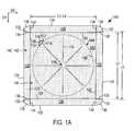
- FIG. 1Ais a schematic top plan view of an exemplary blank according to various aspects of the invention, having a square base panel;
- FIG. 1Bis a schematic perspective view of an exemplary tray formed from the blank of FIG. 1A , according to various aspects of the invention
- FIG. 1Cis a schematic perspective view of the tray of FIG. 1B containing a food item
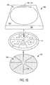
- FIG. 1Dis a schematic exploded view of the tray of FIG. 1B being separated into a heating, browning, and/or crisping disk and a heating, browning, and/or crisping ring, according to various aspects of the invention
- FIG. 1Eis a schematic exploded view of the heating, browning, and/or crisping disk and ring of FIG. 1D in use with a food item;
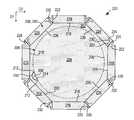
- FIG. 2Ais a schematic top plan view of another exemplary blank that may be used to form a construct according to various aspects of the invention, having a substantially octagonal base panel;
- FIG. 2Bis a schematic perspective view of an exemplary tray formed from the blank of FIG. 2A , according to various aspects of the invention, in an inverted configuration;
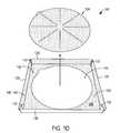
- FIG. 2Cis a schematic exploded view of the tray of FIG. 2B separated into a heating, browning, and/or crisping disk and a heating, browning, and/or crisping ring, according to various aspects of the invention, in use with a food item;
- FIG. 3is a schematic top plan view of a variation of the blank of FIG. 2A , including a plurality of microwave energy transparent areas and a plurality of venting channels;
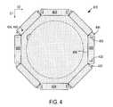
- FIG. 4is a schematic top plan view of another variation of the blank of FIG. 2A , including alternate locking tabs and receiving slits;
- FIG. 5Ais a schematic cross-sectional view of an exemplary microwave energy interactive insulating material that may be used in accordance with various aspects of the invention.
- FIG. 5Bis a schematic perspective view of the microwave energy interactive insulating material of FIG. 5A , in the form of a cut sheet;
- FIG. 5Cis a schematic perspective view of the microwave energy interactive insulating material of FIG. 5B , after sufficient exposure to microwave energy;
- FIG. 5Dis a schematic cross-sectional view of a variation of the exemplary microwave energy interactive insulating material of FIG. 5A ;
- FIG. 6is a schematic cross-sectional view of another microwave energy interactive insulating material that may be used in accordance with the invention.
- FIG. 7is a schematic cross-sectional view of yet another microwave energy interactive insulating material that may be used in accordance with the invention.
- FIG. 8Ais a schematic cross-sectional view of yet another exemplary microwave energy interactive insulating material that may be used in accordance with various aspects of the invention.
- FIG. 8Bis a schematic perspective view of the microwave energy interactive insulating material of FIG. 8A , after sufficient exposure to microwave energy.
- FIG. 1Adepicts an exemplary blank 100 according to various aspects of the present invention.
- the blank 100includes a plurality of adjoined panels.
- each of the various panels and the blankgenerally has a first dimension, for example, a length, extending in a first direction, for example, a longitudinal direction, D 1 , and a second dimension, for example, a width, extending in a second direction, for example, a transverse direction, D 2 .
- first dimensionfor example, a length, extending in a first direction, for example, a longitudinal direction, D 1
- a second dimensionfor example, a width, extending in a second direction, for example, a transverse direction, D 2 .
- the blank 100includes a main panel or major panel or base panel 102 comprising a removable portion 104 defined at least partially by a line of disruption, for example, tear line 106 .
- the base panel 102is substantially square in shape and the removable panel or portion 104 is substantially circular in shape.
- the base panel and removable panelmay independently have any other desired shape, for example, circular, oval, triangular, square, rectangular, pentagonal, hexagonal, heptagonal, octagonal, or any other regular or irregular shape.
- the shape of the various panels and the resulting constructmay be determined by the shape of the food product, and it will be understood that different shapes are contemplated for different food products, for example, sandwiches, pizzas, pastries, doughs, and so forth.
- the removable portion 104includes a tab 108 defined by a line of disruption, for example, cut line 110 , which initiates and terminates at endpoints 112 proximate to tear line 106 .
- cut line 110is substantially arcuate in shape, such that tab 108 is substantially semi-circular in shape.
- the tabmay have any shape as needed or desired.
- the tabmay be oval, rectangular, square, diamond-shaped, trapezoidal, polygonal, or any other regular or irregular shape.
- tear line 106may be interrupted by a score line 114 that extends substantially between endpoints 112 .
- the removable portion 104includes a plurality of score lines or indentations 116 extending radially from a central area 118 of the panel 104 .
- the blank 100includes eight indentations.
- the blankmay include one, two, three, four, five, six, seven, eight, nine, ten, or any number of indentations as needed or desired for a particular application.
- Such indentationsmay serve as venting channels for moisture, as will be discussed further below.
- the indentations 116may be formed in the opposite side of the panel 104 to form upwardly extending elongate protrusions.
- the blank 100also includes a plurality of minor panels or side panels extending from the base panel 104 .
- the blank 100includes a first pair of opposed side panels 120 joined to the base panel 104 along respective fold lines 122 , each of which corresponds generally to an edge of the substantially square base panel 104 .
- Side panels 120are somewhat trapezoidal in shape, with fold lines 122 having a length L 1 less than the length L 2 of panels 120 along edges 124 .
- the blank 100also includes a second pair of opposed side panels 126 joined to the base panel 104 along respective fold lines 128 , each of which also corresponds generally to an edge of the substantially square base panel 104 .
- Side panels 126are substantially rectangular in shape, with fold lines 128 having a length L 3 approximately equal to the length L 4 of panels 126 along edges 130 .
- a pair of opposed end panels 132is joined to each side panel 126 along respective fold lines 134 . End panels 132 are separated from side panels 120 by respective cut lines or slits 136 . If desired, end panels 132 may have tapered or “clipped” corners 138 to facilitate folding of the blank 100 into a container 144 ( FIG. 1B ).
- a microwave energy interactive element 140may overlie at least a portion of the blank 100 , as shown schematically by stippling in FIG. 1A .
- the microwave energy interactive elementmay define at least a portion of a first surface 142 of the blank 100 , and at least a portion of a first or interior surface 142 of a construct 144 formed from the blank 100 , as shown schematically by stippling in FIGS. 1B and 1C .
- the microwave energy interactive elementcomprises a susceptor.
- other microwave energy interactive elementssuch as those described below, are contemplated for use with the invention.
- end panels 132may be folded toward side panels 126 along fold lines 134 .
- side panels 120 , 126may be folded toward the base panel 102 along respective fold lines 122 , 128 to form somewhat upstanding members or walls, as shown in FIG. 1B .
- end panels 132may be joined to side panels 120 using an adhesive, a weld, or any other suitable technique.
- the construct 144comprises a tray that may be used to contain a food item F, for example, a pizza, fruit or meat pie or other pastry, or a sandwich, as shown in FIG. 1C .
- a food item Ffor example, a pizza, fruit or meat pie or other pastry, or a sandwich
- the tray 144 with the food item thereinmay be placed into an outer carton or bag (not shown), or may be sealed with an overwrap (not shown).
- the food itemmay be provided separately from the tray, and/or the tray may be provided in a collapsed or flattened configuration.
- any food item F seated within the tray 144may be removed.
- the userthen may use a finger or other implement to apply pressure to tab 108 , thereby causing it to fold or deflect away from the plane of the base panel 102 along score line 114 ( FIG. 1B ).
- the removable panel 104may be separated from the remainder of the construct 144 along tear line 106 , as shown in FIG. 1D , thereby forming a void or opening 146 in the base panel 102 .
- the remainder of the base panel 102comprises a peripheral area 148 that circumscribes the opening 146 .
- the removable panel 104may be used as a heating, browning, and/or crisping card or disk 104 .
- a food item Fmay be seated on the disk 104 at least partially overlying the microwave energy interactive element 140 , for example, the susceptor.
- the susceptor 140converts microwave energy to thermal energy, which then can be transferred to the bottom of the food item F in proximate or intimate contact with the susceptor 140 .
- indentations 116may serve as venting channels that direct moisture away from the center of the food item, thereby further enhancing heating, browning, and/or crisping.
- the remainder of the construct 144may be used as a heating, browning, and/or crisping cover or somewhat square shaped “ring” 150 to heat, brown, and/or crisp at least a portion of the upper surface of the food item F and, optionally, at least a portion of the sides of the food item F.
- the ring 150may be inverted, thereby exposing a second or outside surface of the ring 150 opposite the first or inside surface 142 , and positioned over the food item F with the microwave energy interactive element 140 , for example, the susceptor, in intimate or proximate contact with the surface of the food item F to be heated, browned, and/or crisped.
- the opening 146generally may overlie the pizza toppings and the peripheral area 148 of the base panel 102 generally may overlie the top portion of the pizza crust.
- the susceptor 140converts microwave energy to thermal energy, which then can be transferred to the top and/or sides of the food item F to enhance heating, browning, and/or crisping of the food item F.
- the ring 150may be supported by side panels or walls 120 , 126 (panels 120 shown in FIG. 1D ), or may rest directly on the food item F with the food item F bearing the weight of the ring 150 .
- the dimensions of base panel 102 and removable panel or disk 104may be selected to adjust which areas of the food item F are brought into proximate and/or intimate contact with the microwave energy interactive element 140 .
- the removable panel or disk 104may be dimensioned to be about the same size as, or larger than, the bottom surface of the food item F.
- the resulting opening 146 formed in panel 102may be so large that a portion of the top surface of the food item to be browned and/or crisped is exposed through the opening 146 and, therefore, not in intimate or proximate contact with the susceptor 140 .
- the size of the disk 104is reduced. As a result, the food item F may extend beyond the dimensions of the disk 104 and may become less brown and/or crisp along the peripheral edges of the bottom surface.
- the base panel 102may be dimensioned to bring the side panels or support elements 120 , 126 into closer proximity with the sides of the food item F, which may further enhance heating, browning, and/or crisping of the areas proximate to the susceptor 140 .
- FIG. 2Adepicts another exemplary blank 200 that may be used in accordance with the invention.
- the blank 200includes a main panel or major panel or base panel 202 comprising a removable portion 204 defined at least partially by a tear line 206 .
- the base panel 202is substantially octagonal in shape and the removable panel or portion 204 is substantially circular in shape.
- other shapesare contemplated hereby.
- the removable portion 204optionally includes a tab 208 defined by a line of disruption, for example, cut line 210 , which initiates and terminates at endpoints 212 proximate to tear line 206 .
- cut line 210is substantially arcuate in shape, such that tab 208 is substantially semi-circular in shape.
- tear line 206may be interrupted by a score line 214 that extends substantially between endpoints 212 .
- the blank 200also includes a plurality of minor panels or side panels extending from the base panel 204 . More particularly, two pairs of opposed side panels 216 are joined to the base panel along fold lines 218 , each of which corresponds generally to an edge of the substantially octagonal base panel 204 .
- the side panels 216are substantially rectangular in shape, although other shapes are contemplated hereby.
- Locking tabs 220are joined to each end of the various side panels 216 along fold lines 222 (only some of the locking tabs 220 and fold lines 222 are labeled in FIG. 2A ). In this example, the locking tabs 220 are somewhat “V” shaped. However, other locking features or connection mechanisms are contemplated for use with the invention.
- the blank 200also includes two pairs of opposed side panels 224 joined to the base panel 204 along fold lines 226 , each of which also corresponds generally to an edge of the substantially octagonal base panel 204 .
- Each of the four side panels 224is arranged in an alternating relation with each of the four side panels 216 .
- Side panels 224are separated from locking tabs 220 by cut lines 228 (only some of which are labeled in FIG. 2A ).
- Each side panel 222includes a pair of opposed receiving slits 230 , each being dimensioned to receive an adjacent locking tab or other locking feature 220 .
- each receiving slit 230includes a first, substantially linear segment 232 that is substantially perpendicular to the respective adjacent fold line 226 , a second, substantially linear segment 234 that is substantially parallel to the respective adjacent fold line 226 , and a third, inwardly arcuate segment 236 that extends between and substantially joins the first segment 232 and the second segment 234 (only one of each of the first, second, and third segments 232 , 234 , 236 are labeled in FIG. 2A ).
- other receiving featuresare contemplated by the invention.
- a microwave energy interactive element 238may overlie at least a portion of the blank 200 , as shown schematically by stippling in FIG. 2A .
- the microwave energy interactive element 238may define at least a portion of a first surface 240 of the blank 200 , and may define at least a portion of a first or inside surface 240 of a construct 242 ( FIGS. 2B and 2C ) formed from the blank 200 .
- the microwave energy interactive elementcomprises a susceptor.
- other microwave energy interactive elementssuch as those described below, are contemplated for use with the invention.
- side panels 216 , 224may be folded toward the first surface 240 of the blank 200 to form generally upstanding members or walls. If desired, the various locking tabs 220 may be inserted into the respective adjacent receiving slits 230 to secure the construct 242 in this configuration, as shown schematically in an inverted position in FIG. 2B .
- the construct 242may be used as a tray or package to contain a food item, as discussed above in connection with FIGS. 1B and 1C .
- the removable panel 204may be separated from the remainder of the construct 242 to form a heating, browning, and/or crisping system 244 including a disk 246 and cover or ring 248 , as shown schematically in FIG. 2C , and may be used to heat, brown, and/or crisp a food item F in the manner generally described in connection with FIGS. 1C-1E .
- the ring 248has an overall octagonal shape that may be more suitable for some microwave ovens that include a turntable and that cannot accommodate the rotation of a square shaped ring.
- the octagonal shape of ring 248provides greater conformance to the sides of the food item F and, therefore, may enhance browning and crisping of the sides of the food item F.
- FIG. 3illustrates another blank 300 that may be used in accordance with the invention.
- the blank 300includes features that are similar to blank 200 shown in FIG. 2A , except for variations noted and variations that will be understood by those of skill in the art. For simplicity, and not limitation, the reference numerals of similar features are preceded in the figures with a “3” instead of a “2”.
- the blank 300may be used to form trays, containers, heating systems, and other constructs according to the invention and may be used to contain, heat, brown, and/or crisp a food item, as described in connection with FIGS. 1B-1H , with variations noted and variations that will be understood by those of skill in the art.
- the blank 300includes a plurality of microwave energy inactive or transparent areas or “apertures” 350 circumscribed by the microwave energy interactive element 338 .
- the microwave energy inactive or transparent areasare somewhat circular in shape and more concentrated near a central area 352 of the base panel 302 .
- other shapes, numbers, and configurations of microwave energy transparent areasare contemplated.
- the number, shape, size, and positioning of such aperturesmay vary for a particular application depending on type of construct being formed from the blank, the food item to be heated therein or thereon, the desired degree of browning and/or crisping, whether direct exposure to microwave energy is needed or desired to attain uniform heating of the food item, the need for regulating the change in temperature of the food item through direct heating, and whether and to what extent there is a need for venting.
- the microwave energy transparent areasmay be formed in any suitable manner, as will be discussed further below.
- the blank 300also includes a plurality of score lines or indentations 354 extending radially from the central area 352 of the base panel 304 .
- the blank 300includes eight indentations. However, any number of such indentations may be used in accordance with the present invention. Such indentations may serve as venting channels, as discussed above in connection with FIGS. 1A and 1E .
- FIG. 4illustrates another blank 400 that may be used in accordance with the invention.
- the blank 400includes features that are similar to blank 200 shown in FIG. 2A , except for variations noted and variations that will be understood by those of skill in the art. For simplicity, and not limitation, the reference numerals of similar features are preceded in the figures with a “4” instead of a “2”.
- the blank 400may be used to form trays, containers, heating systems, and other constructs according to the invention and may be used to contain, heat, brown, and/or crisp a food item, as described in connection with FIGS. 1B-1H , with variations noted and variations that will be understood by those of skill in the art.
- each side panel 424includes a pair of substantially parallel receiving slits 430 , each dimensioned to receive an adjacent locking tab 420 .
- Each slit 430is substantially perpendicular to the respective adjacent fold line 426 .
- each locking tab 420is separated from the adjacent panel 424 by a cutout 450 .
- the precise shape and dimension of cutout 450may vary for a particular application.
- Numerous other blanks and constructsare contemplated by the invention.
- numerous materialsmay be suitable for use in forming the various blanks and constructs of the invention, provided that the materials are resistant to softening, scorching, combusting, or degrading at typical microwave oven heating temperatures, for example, at from about 250° F. to about 425° F.
- the particular materials usedmay include microwave energy interactive materials and microwave energy transparent or inactive materials.
- any of the various constructs of the present inventionmay include one or more features that alter the effect of microwave energy during the heating or cooking of the food item.
- the constructinclude one or more microwave energy interactive elements (hereinafter sometimes referred to as “microwave interactive elements”) that promote browning and/or crisping of a particular area of the food item, shield a particular area of the food item from microwave energy to prevent overcooking thereof, or transmit microwave energy towards or away from a particular area of the food item.
- microwave interactive elementscomprises one or more microwave energy interactive materials or segments arranged in a particular configuration to absorb microwave energy, transmit microwave energy, reflect microwave energy, or direct microwave energy, as needed or desired for a particular microwave heating construct and food item.
- the microwave interactive elementmay be supported on a microwave inactive or transparent substrate for ease of handling and/or to prevent contact between the microwave interactive material and the food item.
- a microwave interactive element supported on a microwave transparent substrateincludes both microwave interactive and microwave inactive elements or components, such constructs are referred to herein as “microwave interactive webs”.
- the microwave energy interactive materialmay be an electroconductive or semiconductive material, for example, a metal or a metal alloy provided as a metal foil; a vacuum deposited metal or metal alloy; or a metallic ink, an organic ink, an inorganic ink, a metallic paste, an organic paste, an inorganic paste, or any combination thereof.
- metals and metal alloysthat may be suitable for use with the present invention include, but are not limited to, aluminum, chromium, copper, inconel alloys (nickel-chromium-molybdenum alloy with niobium), iron, magnesium, nickel, stainless steel, tin, titanium, tungsten, and any combination or alloy thereof.
- the microwave energy interactive materialmay comprise a metal oxide.
- metal oxidesthat may be suitable for use with the present invention include, but are not limited to, oxides of aluminum, iron, and tin, used in conjunction with an electrically conductive material where needed.
- ITOindium tin oxide
- ITOcan be used as a microwave energy interactive material to provide a heating effect, a shielding effect, a browning and/or crisping effect, or a combination thereof.
- ITOmay be sputtered onto a clear polymeric film. The sputtering process typically occurs at a lower temperature than the evaporative deposition process used for metal deposition.
- ITOhas a more uniform crystal structure and, therefore, is clear at most coating thicknesses. Additionally, ITO can be used for either heating or field management effects. ITO also may have fewer defects than metals, thereby making thick coatings of ITO more suitable for field management than thick coatings of metals, such as aluminum.
- the microwave energy interactive materialmay comprise a suitable electroconductive, semiconductive, or non-conductive artificial dielectric or ferroelectric.
- Artificial dielectricscomprise conductive, subdivided material in a polymeric or other suitable matrix or binder, and may include flakes of an electroconductive metal, for example, aluminum.
- the microwave interactive elementmay comprise a thin layer of microwave interactive material that tends to absorb microwave energy, thereby generating heat at the interface with a food item.
- Such elementsoften are used to promote browning and/or crisping of the surface of a food item (sometimes referred to as a “browning and/or crisping element”).
- a susceptor filmWhen supported on a film or other substrate, such an element may be referred to as a “susceptor film” or, simply, “susceptor”.
- the blank 100includes a susceptor film 140 substantially overlying and at least partially defining a first surface 142 (e.g. substantially one side) of the blank 100 .
- a susceptor film 140substantially overlying and at least partially defining a first surface 142 (e.g. substantially one side) of the blank 100 .
- other microwave energy interactive elementssuch as those described herein, are contemplated hereby.
- the microwave interactive elementmay comprise a foil having a thickness sufficient to shield one or more selected portions of the food item from microwave energy (sometimes referred to as a “shielding element”).
- shielding elementsmay be used where the food item is prone to scorching or drying out during heating.
- the shielding elementmay be formed from various materials and may have various configurations, depending on the particular application for which the shielding element is used.
- the shielding elementis formed from a conductive, reflective metal or metal alloy, for example, aluminum, copper, or stainless steel.
- the shielding elementgenerally may have a thickness of from about 0.000285 inches to about 0.05 inches. In one aspect, the shielding element has a thickness of from about 0.0003 inches to about 0.03 inches. In another aspect, the shielding element has a thickness of from about 0.00035 inches to about 0.020 inches, for example, 0.016 inches.
- the microwave interactive elementmay comprise a segmented foil, such as, but not limited to, those described in U.S. Pat. Nos. 6,204,492, 6,433,322, 6,552,315, and 6,677,563, each of which is incorporated by reference in its entirety.
- segmented foilsare not continuous, appropriately spaced groupings of such segments often act as a transmitting element to direct microwave energy to specific areas of the food item.
- Such foilsalso may be used in combination with browning and/or crisping elements, for example, susceptors.
- the microwave interactive elementmay comprise a foil having a thickness sufficient to shield one or more selected portions of the food item from microwave energy (sometimes referred to as a “shielding element”). Such shielding elements may be used where the food item is prone to scorching or drying out during heating.
- the shielding elementmay be formed from various materials and may have various configurations, depending on the particular application for which the shielding element is used.
- the shielding elementis formed from a conductive, reflective metal or metal alloy, for example, aluminum, copper, or stainless steel.
- the shielding elementgenerally may have a thickness of from about 0.000285 inches to about 0.05 inches. In one aspect, the shielding element has a thickness of from about 0.0003 inches to about 0.03 inches. In another aspect, the shielding element has a thickness of from about 0.00035 inches to about 0.020 inches, for example, 0.016 inches.
- the microwave interactive elementmay comprise a segmented foil, such as, but not limited to, those described in U.S. Pat. Nos. 6,204,492, 6,433,322, 6,552,315, and 6,677,563, each of which is incorporated by reference in its entirety.
- segmented foilsare not continuous, appropriately spaced groupings of such segments often act as a transmitting element to direct microwave energy to specific areas of the food item.
- Such foilsalso may be used in combination with browning and/or crisping elements, for example, susceptors.
- any of the numerous microwave interactive elements described herein or contemplated herebymay be substantially continuous, that is, without substantial breaks or interruptions, or may be discontinuous, for example, by including one or more breaks or apertures that transmit microwave energy therethrough.
- the breaks or aperturesmay be sized and positioned to heat particular areas of the food item selectively. The number, shape, size, and positioning of such breaks or apertures may vary for a particular application depending on type of construct being formed, the food item to be heated therein or thereon, the desired degree of shielding, browning, and/or crisping, whether direct exposure to microwave energy is needed or desired to attain uniform heating of the food item, the need for regulating the change in temperature of the food item through direct heating, and whether and to what extent there is a need for venting.
- the aperturemay be a physical aperture or void in the material used to form the construct, or may be a non-physical “aperture”.
- a non-physical aperturemay be a portion of the construct that is microwave energy inactive by deactivation or otherwise, or one that is otherwise transparent to microwave energy (e.g. apertures 350 in FIG. 3 ).
- the aperturemay be a portion of the construct formed without a microwave energy active material or, alternatively, may be a portion of the construct formed with a microwave energy active material that has been deactivated. While both physical and non-physical apertures allow the food item to be heated directly by the microwave energy, a physical aperture also provides a venting function to allow steam or other vapors to be released from the food item.
- any of the above elements and numerous others contemplated herebymay be supported on a substrate.
- the substratetypically comprises an electrical insulator, for example, a polymeric film or material.
- polymeror “polymeric material” includes, but is not limited to, homopolymers, copolymers, such as for example, block, graft, random, and alternating copolymers, terpolymers, etc. and blends and modifications thereof.
- polymershall include all possible geometrical configurations of the molecule. These configurations include, but are not limited to isotactic, syndiotactic, and random symmetries.
- the thickness of the filmtypically may be from about 35 gauge to about 10 mil. In one aspect, the thickness of the film is from about 40 to about 80 gauge. In another aspect, the thickness of the film is from about 45 to about 50 gauge. In still another aspect, the thickness of the film is about 48 gauge.
- polymeric filmsthat may be suitable include, but are not limited to, polyolefins, polyesters, polyamides, polyimides, polysulfones, polyether ketones, cellophanes, or any combination thereof.
- Other non-conducting substrate materialssuch as paper and paper laminates, metal oxides, silicates, cellulosics, or any combination thereof, also may be used.
- the polymeric filmcomprises polyethylene terephthalate (PET).
- PETpolyethylene terephthalate
- Polyethylene terephthalate filmsare used in commercially available susceptors, for example, the QWIKWAVE® Focus susceptor and the MICRORITE® susceptor, both available from Graphic Packaging International (Marietta, Ga.).
- Examples of polyethylene terephthalate films that may be suitable for use as the substrateinclude, but are not limited to, MELINEX®, commercially available from DuPont Teijan Films (Hopewell, Va.), SKYROL, commercially available from SKC, Inc. (Covington, Ga.), and BARRIALOX PET, available from Toray Films (Front Royal, Va.), and QU50 High Barrier Coated PET, available from Toray Films (Front Royal, Va.).
- the polymeric filmmay be selected to impart various properties to the microwave interactive web, for example, printability, heat resistance, or any other property.
- the polymeric filmmay be selected to provide a water barrier, oxygen barrier, or a combination thereof.
- barrier film layersmay be formed from a polymer film having barrier properties or from any other barrier layer or coating as desired.
- Suitable polymer filmsmay include, but are not limited to, ethylene vinyl alcohol, barrier nylon, polyvinylidene chloride, barrier fluoropolymer, nylon 6, nylon 6,6, coextruded nylon 6/EVOH/nylon 6, silicon oxide coated film, barrier polyethylene terephthalate, or any combination thereof.
- Another example of a barrier film that may be suitableis CAPRAN® OXYSHIELD OBS monoaxially oriented coextruded nylon 6/ethylene vinyl alcohol (EVOH)/nylon 6, also commercially available from Honeywell International.
- Yet another example of a barrier film that may be suitable for use with the present inventionis DARTEK® N-201 nylon 6,6, commercially available from Enhance Packaging Technologies (Webster, N.Y.). Additional examples include BARRIALOX PET, available from Toray Films (Front Royal, Va.) and QU50 High Barrier Coated PET, available from Toray Films (Front Royal, Va.), referred to above.
- a susceptormay have a structure including a film, for example, polyethylene terephthalate, with a layer of silicon oxide coated onto the film, and ITO or other material deposited over the silicon oxide. If needed or desired, additional layers or coatings may be provided to shield the individual layers from damage during processing.
- the barrier filmmay have an oxygen transmission rate (OTR) as measured using ASTM D3985 of less than about 20 cc/m 2 /day.
- OTRoxygen transmission rate
- the barrier filmhas an OTR of less than about 10 cc/m 2 /day.
- the barrier filmhas an OTR of less than about 1 cc/m 2 /day.
- the barrier filmhas an OTR of less than about 0.5 cc/m 2 /day.
- the barrier filmhas an OTR of less than about 0.1 cc/m 2 /day.
- the barrier filmmay have a water vapor transmission rate (WVTR) of less than about 100 g/m 2 /day as measured using ASTM F1249.
- WVTRwater vapor transmission rate
- the barrier filmhas a WVTR of less than about 50 g/m 2 /day.
- the barrier filmhas a WVTR of less than about 15 g/m 2 /day.
- the barrier filmhas a WVTR of less than about 1 g/m 2 /day.
- the barrier filmhas a WVTR of less than about 0.1 g/m 2 /day.
- the barrier filmhas a WVTR of less than about 0.05 g/m 2 /day.
- non-conducting substrate materialssuch as metal oxides, silicates, cellulosics, or any combination thereof, also may be used in accordance with the present invention.
- the microwave energy interactive materialmay be applied to the substrate in any suitable manner, and in some instances, the microwave energy interactive material is printed on, extruded onto, sputtered onto, evaporated on, or laminated to the substrate.
- the microwave energy interactive materialmay be applied to the substrate in any pattern, and using any technique, to achieve the desired heating effect of the food item.
- the microwave energy interactive materialmay be provided as a continuous or discontinuous layer or coating including circles, loops, hexagons, islands, squares, rectangles, octagons, and so forth. Examples of various patterns and methods that may be suitable for use with the present invention are provided in U.S. Pat. Nos.
- microwave interactive element or microwave interactive webmay be joined to or overlie a dimensionally stable, microwave energy transparent support (hereinafter referred to as “microwave transparent support”, “microwave inactive support” or “support”) to form the construct.
- microwave transparent supportmicrowave energy transparent support
- microwave inactive supportsupport
- the supportmay be formed at least partially from a paperboard material, which may be cut into a blank prior to use in the construct.
- the supportmay be formed from paperboard having a basis weight of from about 60 to about 330 lbs/ream, for example, from about 80 to about 140 lbs/ream.
- the paperboardgenerally may have a thickness of from about 6 to about 30 mils, for example, from about 12 to about 28 mils. In one particular example, the paperboard has a thickness of about 12 mils.
- Any suitable paperboardmay be used, for example, a solid bleached or solid unbleached sulfate board, such as SUS® board, commercially available from Graphic Packaging International.
- the supportmay comprise a paper or paper-based material generally having a basis weight of from about 15 to about 60 lbs/ream, for example, from about 20 to about 40 lbs/ream. In one particular example, the paper has a basis weight of about 25 lbs/ream.
- one or more portions of the various blanks or other constructs described herein or contemplated herebymay be coated with varnish, clay, or other materials, either alone or in combination.
- the coatingmay then be printed over with product advertising or other information or images.
- the blanks or other constructsalso may be coated to protect any information printed thereon.
- the blanks or other constructsmay be coated with, for example, a moisture and/or oxygen barrier layer, on either or both sides, such as those described above.
- a moisture and/or oxygen barrier layeron either or both sides, such as those described above.
- Any suitable moisture and/or oxygen barrier materialmay be used in accordance with the present invention. Examples of materials that may be suitable include, but are not limited to, polyvinylidene chloride, ethylene vinyl alcohol, DuPont DARTEKTM nylon 6,6, and others referred to above.
- any of the blanks or other constructs of the present inventionmay be coated or laminated with other materials to impart other properties, such as absorbency, repellency, opacity, color, printability, stiffness, or cushioning.
- absorbent susceptorsare described in U.S. Provisional Application No. 60/604,637, filed Aug. 25, 2004, and U.S. Patent Application Publication No. 2006/0049190 A1, both of which are incorporated herein by reference in their entirety.
- the blanks or other constructsmay include graphics or indicia printed thereon.
- the microwave interactive elementmay have a grey or silver color this is visually distinguishable from the substrate or the support.
- the present inventioncontemplates using a silver or grey toned adhesive to join the microwave interactive elements to the substrate, using a silver or grey toned substrate to mask the presence of the silver or grey toned microwave interactive element, using a dark toned substrate, for example, a black toned substrate, to conceal the presence of the silver or grey toned microwave interactive element, overprinting the metallized side of the web with a silver or grey toned ink to obscure the color variation, printing the non-metallized side of the web with a silver or grey ink or other concealing color in a suitable pattern or as a solid color layer to mask or conceal the presence of the microwave interactive element, or any other suitable technique or combination thereof.
- microwave energy interactive insulating materialany arrangement or combination of layers of materials that is both responsive to microwave energy and capable of providing some degree of thermal insulation when used to heat a food item.
- An insulating materialmay be used to form all or a portion of a blank or construct according to the present invention.
- all or a portion of the microwave energy interactive elements 140 , 238 , 338 , 438 shown schematically by stippling in FIGS. 1A-4may comprise a microwave energy interactive insulating material.
- FIG. 1A-4schematically illustrate a microwave energy interactive elements 140 , 238 , 338 , 438 defining substantially all of the respective first surfaces 142 , 240 , 340 , 440 of the various blanks 100 , 200 , 300 , 400 and constructs 144 , 242 , 244 , it will be understood that the microwave energy interactive insulating material may overlie only a portion of the blank or construct according to the invention.
- an insulating materialoverlies the removable panel or portion of the construct, and therefore, the heating, browning, and/or crisping card or disk
- the usermay be instructed to place the food item on the side of the disk overlying the insulating material or on the opposite side, such that the insulating material rests on the floor of the microwave oven.
- the precise instructions provided to the usermay depend on the desired degree of heating, browning, crisping, and thermal insulation for the particular food item, or may depend on numerous other factors.
- the insulating material or structurecomprises one or more susceptor layers in combination with one or more expandable insulating cells.
- the insulating materialmay include one or more microwave energy transparent or inactive materials to provide dimensional stability, to improve ease of handling the microwave energy interactive material, and/or to prevent contact between the microwave energy interactive material and the food item.
- an insulating materialmay comprise a microwave energy interactive material supported on a first polymeric film layer, a moisture-containing layer superposed with the microwave energy interactive material, and a second polymeric film layer joined to the moisture-containing layer in a predetermined pattern, thereby forming one or more closed cells between the moisture-containing layer and the second polymeric film layer. The closed cells expand or inflate in response to being exposed to microwave energy, thereby causing the microwave energy interactive structure to bulge and deform.
- FIGS. 5A-8BSeveral exemplary insulating materials are depicted in FIGS. 5A-8B . It will be understood that the layer widths are not necessarily shown in perspective. In some instances, for example, the adhesive layers may be very thin with respect to other layers, but are nonetheless shown with some thickness for purposes of clearly illustrating the arrangement of layers.
- FIG. 5Adepicts an exemplary microwave energy interactive insulating material 500 that may be suitable for use with the various aspects of the invention.
- a thin layer of microwave energy interactive material that serves as a susceptor 502is supported on a first polymer film 504 (collectively forming a “susceptor film”) and bonded by lamination with an adhesive 506 (or otherwise) to a dimensionally stable substrate 508 , for example, paper.
- the substrate 508is bonded to a second polymer film 510 using a patterned adhesive 512 or other material, thereby forming a plurality of expandable insulating cells 514 .
- the insulating material 500may be cut and provided as a substantially flat, multi-layered sheet 516 , as shown in FIG. 5B .
- the susceptor 502heats upon impingement by microwave energy, water vapor and other gases typically held in the substrate 508 , for example, paper, and any air trapped within the closed cells 514 between the second polymer film 510 and the substrate 508 , expand, as shown in FIG. 5C .
- the resulting insulating material 516 ′has a quilted or pillowed or lofted top surface 518 and bottom surface 520 .
- the cells 514typically deflate and the insulating structure returns to a somewhat flattened state.
- the insulating material 500may be modified to form a structure 522 that includes an additional paper or polymer film layer 524 joined to the first polymer film layer 504 using an adhesive 526 or other suitable material, as shown in FIG. 5D .
- FIG. 6illustrates another exemplary insulating material 600 .
- the material 600includes a polymer film layer 602 , a susceptor layer 604 , an adhesive layer 606 , and a paper layer 608 .
- the material 600may include a second polymer film layer 610 , an adhesive 612 , and a paper layer 614 .
- the layersmay be adhered or affixed by a patterned adhesive 616 that defines a plurality of closed expandable cells 618 .
- FIG. 7illustrates yet another exemplary insulating material 700 that may be suitable for use with the invention.
- the insulating material 700includes a pair of adjoined, symmetrical layer arrangements. If desired, the two symmetrical arrangements may be formed by folding one layer arrangement onto itself.
- the first symmetrical layer arrangementbegins at the top of the drawing, comprises a polymer film layer 702 , a susceptor layer 704 , an adhesive layer 706 , and a paper or paperboard layer 708 .
- the adhesive layer 706bonds the polymer film 702 and the susceptor layer 704 to the paperboard layer 708 .
- the second symmetrical layer arrangementalso comprises a polymer film layer 710 , a susceptor layer 712 , an adhesive layer 714 , and a paper or paperboard layer 716 .
- a patterned adhesive layer 718is provided between the two paper layers 708 , 716 , and defines a pattern of closed cells 720 configured to expand when exposed to microwave energy.
- an insulating material 700 having respective susceptors 704 , 712 on each side of the expandable insulating cells 720more heat is generated, thereby achieving greater loft of the cells 720 .
- such a materialis able to elevate a food item seated thereon to a greater extent than an insulating material having a single susceptor layer.
- each of the exemplary insulating materials depicted in FIGS. 5A-7include a moisture-containing layer (e.g. paper) that is believed to release at least a portion of the vapor that inflates the expandable cells.
- a moisture-containing layere.g. paper
- structures that are adapted to inflate without such moisture-containing layersalso may be used in accordance with the invention.
- FIG. 8Aillustrates one example of an expandable cell insulating material 800 that is adapted to inflate without the use of a moisture-containing layer, for example, paper.
- one or more reagentsare used to generate a gas that expands the cells of the insulating material.
- the reagentsmay comprise sodium bicarbonate (NaHCO 3 ) and a suitable acid. When exposed to heat, the reagents react to produce carbon dioxide.
- the reagentmay comprise a blowing agent.
- blowing agentsexamples include, but are not limited to, p-p′-oxybis(benzenesulphonylhydrazide), azodicarbonamide, and p-toluenesulfonylsemicarbazide.
- blowing agentsinclude, but are not limited to, p-p′-oxybis(benzenesulphonylhydrazide), azodicarbonamide, and p-toluenesulfonylsemicarbazide.
- numerous other reagents and released gasesare contemplated hereby.
- a thin layer of microwave interactive material 802is supported on a first polymer film 804 to form a susceptor film 806 .
- One or more reagents 808lie adjacent at least a portion of the layer of microwave interactive material 802 .
- the reagent 808 coated susceptor film 806is joined to a second polymer film 810 using a patterned adhesive 812 or other material, or using thermal bonding, ultrasonic bonding, or any other suitable technique, such that closed cells 814 (shown as a void) are formed in the material 800 .
- the microwave interactive material 802heats upon impingement by microwave energy, water vapor or other gases are released from or generated by the reagent 808 .
- the resulting gasapplies pressure on the susceptor film 806 on one side and the second polymer film 810 on the other side of the closed cells 814 .
- Each side of the material 800reacts simultaneously, but uniquely, to the heating and vapor expansion to form a pillowed or quilted insulating material 800 ′ ( FIG. 8B ). This expansion may occur within 1 to 15 seconds in an energized microwave oven, and in some instances, may occur within 2 to 10 seconds.
- any of the microwave energy interactive insulating materials described herein or contemplated herebymay include an adhesive pattern or thermal bond pattern that is selected to enhance cooking of a particular food item.
- the adhesive patternmay be selected to form substantially uniformly shaped expandable cells.
- the adhesive patternmay be selected to form a plurality of different sized cells to allow the individual items to be variably contacted on their various surfaces. While several examples are provided herein, it will be understood that numerous other patterns are contemplated hereby, and the pattern selected will depend on the heating, browning, crisping, and insulating needs of the particular food item.
- multiple layers of insulating materials and other microwave energy interactive elementsmay be used to enhance the insulating properties of the insulating material and, therefore, enhance the browning and crisping of the food item.
- the layersmay remain separate or may be joined using any suitable process or technique, for example, thermal bonding, adhesive bonding, ultrasonic bonding or welding, mechanical fastening, or any combination thereof.
- two sheets of an insulating materialmay be arranged so that their respective susceptor film layers are facing away from each other.
- two sheets of an insulating materialmay be arranged so that their respective susceptor film layers are facing towards each other.
- multiple sheets of an insulating materialmay be arranged in a like manner and superposed.
- multiple sheets of various insulating materialsare superposed in any other configuration as needed or desired for a particular application.
- an insulating materialmay be superposed with one or more additional layers of susceptors or susceptor films.
- constructsare provided herein, it will be understood that any configuration of components may be used as needed or desired.
- the constructmay be flexible, semi-rigid, rigid, or may include a variety of components having different degrees of flexibility. Additionally, it should be understood that the present invention contemplates constructs for single-serving portions and for multiple-serving portions. It also should be understood that various components used to form the constructs of the present invention may be interchanged. Thus, while only certain combinations are illustrated herein, numerous other combinations and configurations are contemplated hereby.
Landscapes
- Engineering & Computer Science (AREA)
- Life Sciences & Earth Sciences (AREA)
- Food Science & Technology (AREA)
- Mechanical Engineering (AREA)
- Cookers (AREA)
- Package Specialized In Special Use (AREA)
- Electric Ovens (AREA)
Abstract
Description
Claims (24)
Priority Applications (1)
| Application Number | Priority Date | Filing Date | Title |
|---|---|---|---|
| US13/437,155US9278795B2 (en) | 2006-07-27 | 2012-04-02 | Microwave heating construct |
Applications Claiming Priority (3)
| Application Number | Priority Date | Filing Date | Title |
|---|---|---|---|
| US83383006P | 2006-07-27 | 2006-07-27 | |
| US11/881,206US8183506B2 (en) | 2006-07-27 | 2007-07-26 | Microwave heating construct |
| US13/437,155US9278795B2 (en) | 2006-07-27 | 2012-04-02 | Microwave heating construct |
Related Parent Applications (1)
| Application Number | Title | Priority Date | Filing Date |
|---|---|---|---|
| US11/881,206ContinuationUS8183506B2 (en) | 2006-07-27 | 2007-07-26 | Microwave heating construct |
Publications (2)
| Publication Number | Publication Date |
|---|---|
| US20120187114A1 US20120187114A1 (en) | 2012-07-26 |
| US9278795B2true US9278795B2 (en) | 2016-03-08 |
Family
ID=38982330
Family Applications (2)
| Application Number | Title | Priority Date | Filing Date |
|---|---|---|---|
| US11/881,206Active2031-02-19US8183506B2 (en) | 2006-07-27 | 2007-07-26 | Microwave heating construct |
| US13/437,155Active2030-03-30US9278795B2 (en) | 2006-07-27 | 2012-04-02 | Microwave heating construct |
Family Applications Before (1)
| Application Number | Title | Priority Date | Filing Date |
|---|---|---|---|
| US11/881,206Active2031-02-19US8183506B2 (en) | 2006-07-27 | 2007-07-26 | Microwave heating construct |
Country Status (5)
| Country | Link |
|---|---|
| US (2) | US8183506B2 (en) |
| EP (2) | EP2772452B1 (en) |
| CA (1) | CA2658237C (en) |
| ES (2) | ES2559267T3 (en) |
| WO (1) | WO2008014377A2 (en) |
Families Citing this family (33)
| Publication number | Priority date | Publication date | Assignee | Title |
|---|---|---|---|---|
| US7323669B2 (en)* | 2002-02-08 | 2008-01-29 | Graphic Packaging International, Inc. | Microwave interactive flexible packaging |
| EP1841668B1 (en)* | 2005-01-14 | 2009-04-22 | Graphic Packaging International, Inc. | Package for browning and crisping dough-based foods in a microwave oven |
| US8853601B2 (en) | 2006-03-31 | 2014-10-07 | Graphic Packaging International, Inc. | Microwavable construct for heating, browning, and crisping rounded food items |
| ATE440791T1 (en)* | 2006-03-31 | 2009-09-15 | Graphic Packaging Int Inc | CONTAINER FOR HEATING, CRISPING AND BROWNING ROUND FOODS IN A MICROWAVE OVEN |
| CA2658237C (en)* | 2006-07-27 | 2011-11-01 | Graphic Packaging International, Inc. | Microwave heating construct |
| ITTO20080346A1 (en)* | 2008-05-09 | 2009-11-10 | Filippo Lizzio | CONTAINER FOR THE TRANSPORT OF HOT AND SIMILAR PIZZAS |
| ES2414207T3 (en) | 2008-08-14 | 2013-07-18 | Graphic Packaging International, Inc. | Packaging structure for microwave heating, with lifting bottom |
| US8710410B2 (en)* | 2008-09-07 | 2014-04-29 | Kraft Foods Group Brands Llc | Tray for microwave cooking and folding of a food product |
| US8815317B2 (en) | 2009-01-12 | 2014-08-26 | Graphic Packaging International, Inc. | Elevated microwave heating construct |
| EP2510285B1 (en) | 2009-12-09 | 2016-01-27 | Graphic Packaging International, Inc. | Deep dish microwave heating construct |
| CA2813421A1 (en)* | 2010-10-21 | 2012-04-26 | Graphic Packaging International, Inc. | Substantially round tray |
| US9078296B2 (en)* | 2011-06-08 | 2015-07-07 | Graphic Packaging International, Inc. | Tray with curved bottom surface |
| US9949593B2 (en) | 2011-10-13 | 2018-04-24 | Smart Packaging, LLC | Embossed paper-based bakeable tray |
| US9744738B2 (en)* | 2011-10-13 | 2017-08-29 | Smart Packaging, LLC | Embossed sheet and method of making and using same |
| US9334100B2 (en)* | 2012-07-18 | 2016-05-10 | Sfc Global Supply Chain, Inc. | Patterned dual susceptor |
| NL1040428C2 (en)* | 2013-10-03 | 2015-04-07 | Ton Kooiman Design Opus Magnum Counseling | PIZZA BOX WITH A ROTATING PLATE ON THE BOTTOM OUTSIDE THE BOX TO MAINTAIN THAT A NEW PIZZA PIECE WILL ALWAYS BE ACCESSIBLE UNDER AN EXTRA REMOVABLE LIEGE IN THE LID, WITH THE PURCHASE OF THE PURPOSE THE COURSE DURING USEFUL USE ALWAYS COVERED TO KEEP IT LONGER WARM. IN WHICH THE ROTATING PLATE MAY ALSO LATER AS A FRISBEE. |
| WO2016073676A1 (en) | 2014-11-07 | 2016-05-12 | Graphic Packaging International, Inc. | Tray for holding a food product |
| US10232973B2 (en) | 2014-11-07 | 2019-03-19 | Graphic Packaging International, Llc | Tray for holding a food product |
| WO2017092913A1 (en)* | 2015-12-02 | 2017-06-08 | Nestec S.A. | Packaged food product for solid state microwave oven |
| EP3383763A1 (en)* | 2015-12-02 | 2018-10-10 | Nestec S.A. | Package for food product |
| US20170253368A1 (en)* | 2016-03-03 | 2017-09-07 | Graphic Packaging International, Inc. | Thermally-Activated Laminate Construct And Methods Of Using The Same |
| EP3883860B1 (en) | 2018-11-20 | 2024-01-03 | Graphic Packaging International, LLC | Adjustable tray, blank for forming a tray and method of forming a tray |
| CA3200678A1 (en) | 2020-11-06 | 2022-05-12 | Graphic Packaging International, Llc | Tray for food products |
| USD1042122S1 (en) | 2021-05-27 | 2024-09-17 | Graphic Packaging International, Llc | Tray |
| USD1042119S1 (en) | 2021-05-27 | 2024-09-17 | Graphic Pachaging International, LLC | Tray |
| USD1042120S1 (en) | 2021-05-27 | 2024-09-17 | Graphic Packaging International, Llc | Tray |
| USD1042118S1 (en) | 2021-05-27 | 2024-09-17 | Graphic Packaging International, Llc | Tray |
| USD1044494S1 (en) | 2021-05-27 | 2024-10-01 | Graphic Packaging International, Llc | Tray |
| USD1042116S1 (en) | 2021-05-27 | 2024-09-17 | Graphic Packaging International, Llc | Carton |
| USD1062459S1 (en) | 2021-05-27 | 2025-02-18 | Graphic Packaging International, Llc | Tray |
| USD1042117S1 (en) | 2021-05-27 | 2024-09-17 | Graphic Packaging International, Llc | Tray |
| USD1042121S1 (en) | 2021-05-27 | 2024-09-17 | Graphic Packaging International, Llc | Tray |
| USD1032377S1 (en) | 2022-08-05 | 2024-06-25 | Conagra Foods Rdm, Inc. | Microwave food pouch with tear strip vent |
Citations (127)
| Publication number | Priority date | Publication date | Assignee | Title |
|---|---|---|---|---|
| US4260060A (en) | 1979-09-17 | 1981-04-07 | Champion International Corporation | Food carton for microwave heating |
| US4267420A (en) | 1978-05-30 | 1981-05-12 | General Mills, Inc. | Packaged food item and method for achieving microwave browning thereof |
| US4268738A (en) | 1977-09-28 | 1981-05-19 | The Procter & Gamble Company | Microwave energy moderator |
| US4279933A (en) | 1980-01-30 | 1981-07-21 | Champion International Corporation | Expandable food package container |
| US4286136A (en) | 1979-12-10 | 1981-08-25 | Mason Jr Stanley I | Cooking container for more efficient cooking in a microwave oven |
| US4567341A (en) | 1984-08-02 | 1986-01-28 | James River-Norwalk, Inc. | Side vented and shielded microwave pizza carton |
| US4626641A (en) | 1984-12-04 | 1986-12-02 | James River Corporation | Fruit and meat pie microwave container and method |
| US4678882A (en) | 1983-07-05 | 1987-07-07 | James River-Norwalk | Packaging container for microwave popcorn popping |
| JPS62191682U (en) | 1986-05-26 | 1987-12-05 | ||
| JPS6316600U (en) | 1986-07-11 | 1988-02-03 | ||
| US4742203A (en) | 1984-08-02 | 1988-05-03 | James River-Norwalk, Inc. | Package assembly and method for storing and microwave heating of food |
| US4745249A (en) | 1987-02-19 | 1988-05-17 | Mrs. Paul's Kitchens Inc. | Package and method for microwave heating of a food product |
| US4775771A (en) | 1987-07-30 | 1988-10-04 | James River Corporation | Sleeve for crisping and browning of foods in a microwave oven and package and method utilizing same |
| JPS6420331U (en) | 1987-07-29 | 1989-02-01 | ||
| US4810844A (en) | 1987-11-30 | 1989-03-07 | Anderson Alan R | Microwave popcorn package |
| JPH0197107A (en) | 1987-10-05 | 1989-04-14 | Mitsubishi Electric Corp | Fixed frame for receiving breaker |
| WO1989004585A1 (en) | 1987-11-10 | 1989-05-18 | The Pillsbury Company | Susceptor in combination with grid for microwave oven package |
| US4835352A (en) | 1986-11-05 | 1989-05-30 | Toppan Printing Co., Ltd. | Package material for microwave cooking |
| US4865921A (en) | 1987-03-10 | 1989-09-12 | James Riker Corporation Of Virginia | Microwave interactive laminate |
| US4883936A (en) | 1988-09-01 | 1989-11-28 | James River Corporation | Control of microwave interactive heating by patterned deactivation |
| US4888459A (en) | 1986-12-18 | 1989-12-19 | Alcan International Limited | Microwave container with dielectric structure of varying properties and method of using same |
| US4891482A (en) | 1988-07-13 | 1990-01-02 | The Stouffer Corporation | Disposable microwave heating receptacle and method of using same |
| US4890439A (en) | 1988-11-09 | 1990-01-02 | James River Corporation | Flexible disposable material for forming a food container for microwave cooking |
| US4894247A (en) | 1987-12-11 | 1990-01-16 | E. I. Du Pont De Nemours And Company | Fibrous microwave susceptor package |
| US4894503A (en) | 1987-10-23 | 1990-01-16 | The Pillsbury Company | Packages materials for shielded food containers used in microwave ovens |
| US4896009A (en) | 1988-07-11 | 1990-01-23 | James River Corporation | Gas permeable microwave reactive package |
| US4916280A (en) | 1987-07-11 | 1990-04-10 | Nestec S.A. | Food package adapted particularly for microwave heating |
| US4933193A (en) | 1987-12-11 | 1990-06-12 | E. I. Du Pont De Nemours And Company | Microwave cooking package |
| US4936935A (en) | 1988-05-20 | 1990-06-26 | Beckett Industries Inc. | Microwave heating material |
| US4940867A (en) | 1988-09-01 | 1990-07-10 | The Stouffer Corporation | Microwave composite sheet stock |
| US4962293A (en) | 1989-09-18 | 1990-10-09 | Dunmore Corporation | Microwave susceptor film to control the temperature of cooking foods |
| US4968865A (en) | 1987-06-01 | 1990-11-06 | General Mills, Inc. | Ceramic gels with salt for microwave heating susceptor |
| US5008507A (en) | 1986-09-02 | 1991-04-16 | The Pillsbury Company | Microwave food products and method of their manufacture |
| US5034234A (en) | 1988-03-15 | 1991-07-23 | Golden Valley Microwave Foods Inc. | Microwave heating and serving package |
| US5039364A (en) | 1988-11-28 | 1991-08-13 | Beckett Industries Inc. | Method of making selective microwave heating material |
| US5041325A (en) | 1987-08-10 | 1991-08-20 | Minnesota Mining And Manufacturing Company | Microwave food package and grease absorbent pad therefor |
| US5053594A (en) | 1989-11-09 | 1991-10-01 | Rich-Seapak Processing Corporation | Cook and serve food package for the storing and heating by microwave energy of a food item |
| US5081330A (en) | 1990-07-11 | 1992-01-14 | Golden Valley Microwave Foods Inc. | Package with microwave induced insulation chambers |
| US5084601A (en) | 1988-03-15 | 1992-01-28 | Golden Valley Microwave Foods Inc. | Microwave receptive heating sheets and packages containing them |
| US5096723A (en) | 1990-07-23 | 1992-03-17 | Golden Valley Microwave Foods Inc. | Microwave food heating package with serving tray |
| US5117078A (en) | 1990-02-02 | 1992-05-26 | Beckett Industries Inc. | Controlled heating of foodstuffs by microwave energy |
| US5140119A (en) | 1984-08-02 | 1992-08-18 | James River Paper Company, Inc. | Package assembly and method for storing and microwave heating of food |
| US5164562A (en) | 1989-08-02 | 1992-11-17 | Westvaco Corporation | Composite susceptor packaging material |
| US5177332A (en) | 1988-04-29 | 1993-01-05 | E. I. Du Pont De Nemours And Company | Microwave energy susceptible conformable laminate packaging materials |
| US5213902A (en) | 1991-02-19 | 1993-05-25 | Beckett Industries Inc. | Microwave oven package |
| US5217768A (en) | 1991-09-05 | 1993-06-08 | Advanced Dielectric Technologies | Adhesiveless susceptor films and packaging structures |
| US5221419A (en) | 1991-02-19 | 1993-06-22 | Beckett Industries Inc. | Method for forming laminate for microwave oven package |
| US5231268A (en) | 1992-03-04 | 1993-07-27 | Westvaco Corporation | Printed microwave susceptor |
| US5239153A (en) | 1988-11-28 | 1993-08-24 | Beckett Industries Inc. | Differential thermal heating in microwave oven packages |
| US5247149A (en) | 1991-08-28 | 1993-09-21 | The Stouffer Corporation | Method and appliance for cooking a frozen pizza pie with microwave energy |
| EP0563999A2 (en) | 1992-04-03 | 1993-10-06 | James River Corporation Of Virginia | Antenna for microwave enhanced cooking |
| US5256846A (en) | 1991-09-05 | 1993-10-26 | Advanced Dielectric Technologies, Inc. | Microwaveable barrier films |
| US5260537A (en) | 1991-06-17 | 1993-11-09 | Beckett Industries Inc. | Microwave heating structure |
| US5260070A (en) | 1991-03-11 | 1993-11-09 | The Stouffer Corporation | Microwave reconstitution of frozen pizza |
| US5266386A (en) | 1991-02-14 | 1993-11-30 | Beckett Industries Inc. | Demetallizing procedure |
| US5294763A (en) | 1989-04-07 | 1994-03-15 | Minnesota Mining And Manufacturing Company | Microwave heatable composites |
| USRE34683E (en) | 1987-03-10 | 1994-08-02 | James River Corporation Of Virginia | Control of microwave interactive heating by patterned deactivation |
| US5334820A (en) | 1992-02-28 | 1994-08-02 | Golden Valley Microwave Foods Inc. | Microwave food heating package with accordion pleats |
| US5340436A (en) | 1991-02-14 | 1994-08-23 | Beckett Industries Inc. | Demetallizing procedure |
| US5354973A (en) | 1992-01-29 | 1994-10-11 | Beckett Industries Inc. | Microwave heating structure comprising an array of shaped elements |
| US5389767A (en) | 1993-01-11 | 1995-02-14 | Dobry; Reuven | Microwave susceptor elements and materials |
| US5405663A (en) | 1991-11-12 | 1995-04-11 | Hunt-Wesson, Inc. | Microwave package laminate with extrusion bonded susceptor |
| US5410135A (en) | 1988-09-01 | 1995-04-25 | James River Paper Company, Inc. | Self limiting microwave heaters |
| US5412187A (en) | 1994-01-25 | 1995-05-02 | Advanced Deposition Technologies, Inc. | Fused microwave conductive structure |
| EP0656301A1 (en) | 1991-04-30 | 1995-06-07 | Frisco-Findus Ag | Food package for microwave ovens |
| US5424517A (en) | 1993-10-27 | 1995-06-13 | James River Paper Company, Inc. | Microwave impedance matching film for microwave cooking |
| US5484984A (en) | 1994-03-04 | 1996-01-16 | Gics & Vermee, L.P. | Ovenable food package including a base with depending leg member and a plurality of raised portions and associated food packages |
| US5510132A (en) | 1994-06-07 | 1996-04-23 | Conagra, Inc. | Method for cooking a food item in microwave heating package having end flaps for elevating and venting the package |
| US5519195A (en) | 1989-02-09 | 1996-05-21 | Beckett Technologies Corp. | Methods and devices used in the microwave heating of foods and other materials |
| US5565125A (en) | 1994-10-24 | 1996-10-15 | Westvaco Corporation | Printed microwave susceptor with improved thermal and migration protection |
| US5585027A (en) | 1994-06-10 | 1996-12-17 | Young; Robert C. | Microwave susceptive reheating support with perforations enabling change of size and/or shape of the substrate |
| WO1997011010A1 (en) | 1995-09-18 | 1997-03-27 | Beckett Technologies Corp. | Microwavable container |
| US5628921A (en) | 1991-02-14 | 1997-05-13 | Beckett Technologies Corp. | Demetallizing procedure |
| JPH09132279A (en) | 1995-11-02 | 1997-05-20 | C I Kasei Co Ltd | Electromagnetic shielding container, electromagnetic shielding sheet, electromagnetic shielding bag, and bento |
| JPH09185991A (en) | 1995-12-28 | 1997-07-15 | New Japan Radio Co Ltd | Receptacle for frozen food |
| US5759422A (en) | 1996-02-14 | 1998-06-02 | Fort James Corporation | Patterned metal foil laminate and method for making same |
| US5770840A (en) | 1995-12-12 | 1998-06-23 | Conagra Frozen Foods | Microwave cooking container for food items |
| US5800724A (en) | 1996-02-14 | 1998-09-01 | Fort James Corporation | Patterned metal foil laminate and method for making same |
| US5864123A (en) | 1995-06-02 | 1999-01-26 | Keefer; Richard M. | Smart microwave packaging structures |
| US5900264A (en) | 1997-11-06 | 1999-05-04 | Gics & Vermee, L.P. | Food package including a tray and a sleeve surrounding the tray |
| US5948308A (en) | 1997-10-22 | 1999-09-07 | Rock-Tenn Company | Food product tray with expandable side panels |
| EP0970895A1 (en) | 1998-07-06 | 2000-01-12 | Sara Lee/DE N.V. | Assembly of a frozen cake and a disposable tray, and method for defrosting a frozen cake |
| US6054698A (en) | 1996-11-01 | 2000-04-25 | Mast; Roy Lee | Microwave retaining package for microwave cooking |
| US6114679A (en) | 1997-01-29 | 2000-09-05 | Graphic Packaging Corporation | Microwave oven heating element having broken loops |
| US6133560A (en) | 1997-02-12 | 2000-10-17 | Fort James Corporation | Patterned microwave oven susceptor |
| US6137099A (en) | 1994-11-17 | 2000-10-24 | Pak Pacific Corporation Pty., Ltd. | Food packaging for microwave cooking having a corrugated susceptor with fold lines |
| US6150646A (en) | 1996-08-26 | 2000-11-21 | Graphic Packaging Corporation | Microwavable container having active microwave energy heating elements for combined bulk and surface heating |
| US6158589A (en) | 1999-09-23 | 2000-12-12 | Motion Design, Inc. | Boxes with internal resilient elements |
| US6168812B1 (en) | 1997-04-29 | 2001-01-02 | Jeno F. Paulucci | Microwavable semi-circular pizza product and packaging combination |
| US6204492B1 (en) | 1999-09-20 | 2001-03-20 | Graphic Packaging Corporation | Abuse-tolerant metallic packaging materials for microwave cooking |
| US6251451B1 (en) | 1996-08-26 | 2001-06-26 | Graphic Packaging Corporation | Microwavable package |
| US20010017297A1 (en) | 1999-09-20 | 2001-08-30 | Neilson Zeng | Abuse-tolerant metallic packaging materials for microwave cooking |
| US6359272B1 (en) | 1999-06-11 | 2002-03-19 | Schwan's Sales Enterprises, Inc. | Microwave package and support tray with features for uniform crust heating |
| GB2368507A (en) | 2000-10-25 | 2002-05-01 | Boxes | Microwave packaging |
| US6414290B1 (en) | 1998-03-19 | 2002-07-02 | Graphic Packaging Corporation | Patterned microwave susceptor |
| US6501059B1 (en) | 1999-09-27 | 2002-12-31 | Roy Lee Mast | Heavy-metal microwave formations and methods |
| US20030010777A1 (en) | 2001-07-10 | 2003-01-16 | Milgrom Mark C. | Food package |
| FR2828394A1 (en) | 2001-08-13 | 2003-02-14 | Marco Polo Foods | DEVICE FOR DEFROSTING AT LEAST ONE SUSHI OR SIMILAR FOOD USING MICROWAVE |
| US6534755B1 (en) | 2001-10-09 | 2003-03-18 | Self Serve Foods, Inc. | Packaging for individually microwaveable portions of food items |
| US6559430B2 (en) | 2001-01-04 | 2003-05-06 | General Mills, Inc. | Foil edge control for microwave heating |
| US20030085224A1 (en) | 2001-11-07 | 2003-05-08 | Tsontzidis Sandra M. | Microwave packaging with indentation patterns |
| US20030111463A1 (en) | 2001-12-14 | 2003-06-19 | Lai Laurence M.C. | Abuse-tolerant metallic pattern arrays for microwave packaging materials |
| WO2003066435A2 (en) | 2002-02-08 | 2003-08-14 | Graphic Packaging International, Inc. | Insulating microwave interactive packaging |
| US20030206997A1 (en) | 2002-05-01 | 2003-11-06 | Schwan's Sales Enterprises, Inc. | Susceptor sleeve for food products |
| US6717121B2 (en) | 2001-09-28 | 2004-04-06 | Graphic Packaging International, Inc. | Patterned microwave susceptor element and microwave container incorporating same |
| US20040149746A1 (en) | 2003-02-05 | 2004-08-05 | Hoese Thomas C. | Reconfigurable microwave package for cooking and crisping food products |
| US20040173607A1 (en) | 2003-01-03 | 2004-09-09 | Blankenbeckler Nicole L. | Article containing microwave susceptor material |
| US20040232213A1 (en) | 2000-04-20 | 2004-11-25 | Mccain Foods Limited | Package for heating a food product |
| US20050042360A1 (en)* | 2003-08-18 | 2005-02-24 | Tiffany Linda E. | Microwavable French fries, packaging and processing |
| WO2005085091A2 (en) | 2004-03-01 | 2005-09-15 | Kraftfoods Holdings, Inc. | Multi-purpose food preparation kit |
| US20050205565A1 (en) | 2004-02-09 | 2005-09-22 | Cole Lorin R | Microwave cooking packages and methods of making thereof |
| US20060049190A1 (en) | 2004-08-25 | 2006-03-09 | Middleton Scott W | Absorbent microwave interactive packaging |
| WO2006076501A1 (en) | 2005-01-14 | 2006-07-20 | Graphic Packaging International, Inc. | Package for browning and crisping dough-based foods in a microwave oven |
| WO2006130789A1 (en) | 2005-06-02 | 2006-12-07 | Schwan's Food Manufacturing, Inc. | Elevated microwaveable carton and susceptor portion and methods |
| US20060289521A1 (en) | 2005-04-14 | 2006-12-28 | Reinhard Bohme | Thermally activatable microwave interactive materials |
| US20070039951A1 (en) | 2005-08-16 | 2007-02-22 | Cole Lorin R | Variable serving size insulated packaging |
| US20070056962A1 (en)* | 2005-04-20 | 2007-03-15 | Hopkins Gary Sr | Susceptor panel for brown and crisp microwaving package |
| US20070087090A1 (en) | 2005-09-12 | 2007-04-19 | Russell Mitchell W | Elevated microwave heating construct |
| EP1840047A1 (en) | 2006-03-31 | 2007-10-03 | Graphic Packaging International, Inc. | Microwavable construct for heating, browning, and crisping rounded food items |
| US20070251943A1 (en) | 2002-02-08 | 2007-11-01 | Wnek Patrick H | Microwave energy interactive heating sheet |
| WO2008014377A2 (en) | 2006-07-27 | 2008-01-31 | Graphic Packaging International, Inc. | Microwave heating construct |
| WO2008052096A1 (en) | 2006-10-26 | 2008-05-02 | Graphic Packaging International, Inc. | Elevated microwave heating tray |
| WO2008115272A2 (en) | 2006-10-16 | 2008-09-25 | Graphic Packaging International, Inc. | Elevated microwave heating construct |
| US20090206074A1 (en) | 2008-02-18 | 2009-08-20 | Schneider Lee M | Apparatus for Cooking Raw Food Items in a Microwave Oven |
| WO2010019758A2 (en) | 2008-08-14 | 2010-02-18 | Graphic Packaging International, Inc. | Microwave heating construct with elevatable bottom |
| US20120000905A1 (en) | 2006-03-31 | 2012-01-05 | Marie-Line Noyelle | Microwavable Construct for Heating, Browning, and Crisping Rounded Food Items |
| US20120100265A1 (en) | 2005-01-14 | 2012-04-26 | Lafferty Terrence P | Package for Browning and Crisping Dough-Based Foods in a Microwave Oven |
Family Cites Families (1)
| Publication number | Priority date | Publication date | Assignee | Title |
|---|---|---|---|---|
| JP3336112B2 (en)* | 1994-04-28 | 2002-10-21 | 富士写真フイルム株式会社 | Splicer |
- 2007
- 2007-07-26CACA2658237Apatent/CA2658237C/enactiveActive
- 2007-07-26ESES14001647.8Tpatent/ES2559267T3/enactiveActive
- 2007-07-26USUS11/881,206patent/US8183506B2/enactiveActive
- 2007-07-26ESES07813392.3Tpatent/ES2479092T3/enactiveActive
- 2007-07-26EPEP14001647.8Apatent/EP2772452B1/enactiveActive
- 2007-07-26WOPCT/US2007/074427patent/WO2008014377A2/enactiveApplication Filing
- 2007-07-26EPEP07813392.3Apatent/EP2049413B1/enactiveActive
- 2012
- 2012-04-02USUS13/437,155patent/US9278795B2/enactiveActive
Patent Citations (156)
| Publication number | Priority date | Publication date | Assignee | Title |
|---|---|---|---|---|
| US4268738A (en) | 1977-09-28 | 1981-05-19 | The Procter & Gamble Company | Microwave energy moderator |
| US4267420A (en) | 1978-05-30 | 1981-05-12 | General Mills, Inc. | Packaged food item and method for achieving microwave browning thereof |
| US4260060A (en) | 1979-09-17 | 1981-04-07 | Champion International Corporation | Food carton for microwave heating |
| US4286136A (en) | 1979-12-10 | 1981-08-25 | Mason Jr Stanley I | Cooking container for more efficient cooking in a microwave oven |
| US4279933A (en) | 1980-01-30 | 1981-07-21 | Champion International Corporation | Expandable food package container |
| US4678882A (en) | 1983-07-05 | 1987-07-07 | James River-Norwalk | Packaging container for microwave popcorn popping |
| US4742203A (en) | 1984-08-02 | 1988-05-03 | James River-Norwalk, Inc. | Package assembly and method for storing and microwave heating of food |
| US4567341A (en) | 1984-08-02 | 1986-01-28 | James River-Norwalk, Inc. | Side vented and shielded microwave pizza carton |
| US5140119A (en) | 1984-08-02 | 1992-08-18 | James River Paper Company, Inc. | Package assembly and method for storing and microwave heating of food |
| US4626641A (en) | 1984-12-04 | 1986-12-02 | James River Corporation | Fruit and meat pie microwave container and method |
| JPS62191682U (en) | 1986-05-26 | 1987-12-05 | ||
| JPS6316600U (en) | 1986-07-11 | 1988-02-03 | ||
| US5008507A (en) | 1986-09-02 | 1991-04-16 | The Pillsbury Company | Microwave food products and method of their manufacture |
| US4835352A (en) | 1986-11-05 | 1989-05-30 | Toppan Printing Co., Ltd. | Package material for microwave cooking |
| US4888459A (en) | 1986-12-18 | 1989-12-19 | Alcan International Limited | Microwave container with dielectric structure of varying properties and method of using same |
| US4745249A (en) | 1987-02-19 | 1988-05-17 | Mrs. Paul's Kitchens Inc. | Package and method for microwave heating of a food product |
| US4865921A (en) | 1987-03-10 | 1989-09-12 | James Riker Corporation Of Virginia | Microwave interactive laminate |
| USRE34683E (en) | 1987-03-10 | 1994-08-02 | James River Corporation Of Virginia | Control of microwave interactive heating by patterned deactivation |
| US4968865A (en) | 1987-06-01 | 1990-11-06 | General Mills, Inc. | Ceramic gels with salt for microwave heating susceptor |
| US4916280A (en) | 1987-07-11 | 1990-04-10 | Nestec S.A. | Food package adapted particularly for microwave heating |
| JPS6420331U (en) | 1987-07-29 | 1989-02-01 | ||
| US4775771A (en) | 1987-07-30 | 1988-10-04 | James River Corporation | Sleeve for crisping and browning of foods in a microwave oven and package and method utilizing same |
| US5041325A (en) | 1987-08-10 | 1991-08-20 | Minnesota Mining And Manufacturing Company | Microwave food package and grease absorbent pad therefor |
| JPH0197107A (en) | 1987-10-05 | 1989-04-14 | Mitsubishi Electric Corp | Fixed frame for receiving breaker |
| US4894503A (en) | 1987-10-23 | 1990-01-16 | The Pillsbury Company | Packages materials for shielded food containers used in microwave ovens |
| WO1989004585A1 (en) | 1987-11-10 | 1989-05-18 | The Pillsbury Company | Susceptor in combination with grid for microwave oven package |
| US4927991A (en) | 1987-11-10 | 1990-05-22 | The Pillsbury Company | Susceptor in combination with grid for microwave oven package |
| US4810844A (en) | 1987-11-30 | 1989-03-07 | Anderson Alan R | Microwave popcorn package |
| US4933193A (en) | 1987-12-11 | 1990-06-12 | E. I. Du Pont De Nemours And Company | Microwave cooking package |
| US4894247A (en) | 1987-12-11 | 1990-01-16 | E. I. Du Pont De Nemours And Company | Fibrous microwave susceptor package |
| US5034234A (en) | 1988-03-15 | 1991-07-23 | Golden Valley Microwave Foods Inc. | Microwave heating and serving package |
| US5084601A (en) | 1988-03-15 | 1992-01-28 | Golden Valley Microwave Foods Inc. | Microwave receptive heating sheets and packages containing them |
| US5177332A (en) | 1988-04-29 | 1993-01-05 | E. I. Du Pont De Nemours And Company | Microwave energy susceptible conformable laminate packaging materials |
| US4936935A (en) | 1988-05-20 | 1990-06-26 | Beckett Industries Inc. | Microwave heating material |
| US4963424A (en) | 1988-05-20 | 1990-10-16 | Beckett Industries Inc. | Microwave heating material |
| US4896009A (en) | 1988-07-11 | 1990-01-23 | James River Corporation | Gas permeable microwave reactive package |
| US4891482A (en) | 1988-07-13 | 1990-01-02 | The Stouffer Corporation | Disposable microwave heating receptacle and method of using same |
| US4940867A (en) | 1988-09-01 | 1990-07-10 | The Stouffer Corporation | Microwave composite sheet stock |
| US4883936A (en) | 1988-09-01 | 1989-11-28 | James River Corporation | Control of microwave interactive heating by patterned deactivation |
| US5410135A (en) | 1988-09-01 | 1995-04-25 | James River Paper Company, Inc. | Self limiting microwave heaters |
| US4890439A (en) | 1988-11-09 | 1990-01-02 | James River Corporation | Flexible disposable material for forming a food container for microwave cooking |
| US5039364A (en) | 1988-11-28 | 1991-08-13 | Beckett Industries Inc. | Method of making selective microwave heating material |
| US5239153A (en) | 1988-11-28 | 1993-08-24 | Beckett Industries Inc. | Differential thermal heating in microwave oven packages |
| US5519195A (en) | 1989-02-09 | 1996-05-21 | Beckett Technologies Corp. | Methods and devices used in the microwave heating of foods and other materials |
| US5294763A (en) | 1989-04-07 | 1994-03-15 | Minnesota Mining And Manufacturing Company | Microwave heatable composites |
| US5164562A (en) | 1989-08-02 | 1992-11-17 | Westvaco Corporation | Composite susceptor packaging material |
| US4962293A (en) | 1989-09-18 | 1990-10-09 | Dunmore Corporation | Microwave susceptor film to control the temperature of cooking foods |
| US5053594A (en) | 1989-11-09 | 1991-10-01 | Rich-Seapak Processing Corporation | Cook and serve food package for the storing and heating by microwave energy of a food item |
| US5117078A (en) | 1990-02-02 | 1992-05-26 | Beckett Industries Inc. | Controlled heating of foodstuffs by microwave energy |
| US5081330A (en) | 1990-07-11 | 1992-01-14 | Golden Valley Microwave Foods Inc. | Package with microwave induced insulation chambers |
| WO1992000899A1 (en) | 1990-07-11 | 1992-01-23 | Golden Valley Microwave Foods, Inc. | Package with microwave induced insulation chambers |
| US5096723A (en) | 1990-07-23 | 1992-03-17 | Golden Valley Microwave Foods Inc. | Microwave food heating package with serving tray |
| US5340436A (en) | 1991-02-14 | 1994-08-23 | Beckett Industries Inc. | Demetallizing procedure |
| US5628921A (en) | 1991-02-14 | 1997-05-13 | Beckett Technologies Corp. | Demetallizing procedure |
| US5672407A (en) | 1991-02-14 | 1997-09-30 | Beckett Technologies Corp. | Structure with etchable metal |
| US5266386A (en) | 1991-02-14 | 1993-11-30 | Beckett Industries Inc. | Demetallizing procedure |
| US5221419A (en) | 1991-02-19 | 1993-06-22 | Beckett Industries Inc. | Method for forming laminate for microwave oven package |
| US5213902A (en) | 1991-02-19 | 1993-05-25 | Beckett Industries Inc. | Microwave oven package |
| US5260070A (en) | 1991-03-11 | 1993-11-09 | The Stouffer Corporation | Microwave reconstitution of frozen pizza |
| EP0656301A1 (en) | 1991-04-30 | 1995-06-07 | Frisco-Findus Ag | Food package for microwave ovens |
| US5260537A (en) | 1991-06-17 | 1993-11-09 | Beckett Industries Inc. | Microwave heating structure |
| US5247149A (en) | 1991-08-28 | 1993-09-21 | The Stouffer Corporation | Method and appliance for cooking a frozen pizza pie with microwave energy |
| US5217768A (en) | 1991-09-05 | 1993-06-08 | Advanced Dielectric Technologies | Adhesiveless susceptor films and packaging structures |
| US5256846A (en) | 1991-09-05 | 1993-10-26 | Advanced Dielectric Technologies, Inc. | Microwaveable barrier films |
| US5405663A (en) | 1991-11-12 | 1995-04-11 | Hunt-Wesson, Inc. | Microwave package laminate with extrusion bonded susceptor |
| US5354973A (en) | 1992-01-29 | 1994-10-11 | Beckett Industries Inc. | Microwave heating structure comprising an array of shaped elements |
| US5334820A (en) | 1992-02-28 | 1994-08-02 | Golden Valley Microwave Foods Inc. | Microwave food heating package with accordion pleats |
| US5231268A (en) | 1992-03-04 | 1993-07-27 | Westvaco Corporation | Printed microwave susceptor |
| EP0563999A2 (en) | 1992-04-03 | 1993-10-06 | James River Corporation Of Virginia | Antenna for microwave enhanced cooking |
| US5389767A (en) | 1993-01-11 | 1995-02-14 | Dobry; Reuven | Microwave susceptor elements and materials |
| US5424517A (en) | 1993-10-27 | 1995-06-13 | James River Paper Company, Inc. | Microwave impedance matching film for microwave cooking |
| US5412187A (en) | 1994-01-25 | 1995-05-02 | Advanced Deposition Technologies, Inc. | Fused microwave conductive structure |
| US5543606A (en) | 1994-03-04 | 1996-08-06 | Gics & Vermee, L.P. | Non-circular ovenable food package having a base with depending leg members and at least one raised portion and associated food package |
| US5484984A (en) | 1994-03-04 | 1996-01-16 | Gics & Vermee, L.P. | Ovenable food package including a base with depending leg member and a plurality of raised portions and associated food packages |
| US5510132A (en) | 1994-06-07 | 1996-04-23 | Conagra, Inc. | Method for cooking a food item in microwave heating package having end flaps for elevating and venting the package |
| US5688427A (en) | 1994-06-07 | 1997-11-18 | Conagra, Inc. | Microwave heating package having end flaps for elevating and venting the package |
| US5585027A (en) | 1994-06-10 | 1996-12-17 | Young; Robert C. | Microwave susceptive reheating support with perforations enabling change of size and/or shape of the substrate |
| US5565125A (en) | 1994-10-24 | 1996-10-15 | Westvaco Corporation | Printed microwave susceptor with improved thermal and migration protection |
| US6137099A (en) | 1994-11-17 | 2000-10-24 | Pak Pacific Corporation Pty., Ltd. | Food packaging for microwave cooking having a corrugated susceptor with fold lines |
| US5864123A (en) | 1995-06-02 | 1999-01-26 | Keefer; Richard M. | Smart microwave packaging structures |
| US5910268A (en) | 1995-06-02 | 1999-06-08 | Keefer; Richard M. | Microwave packaging structures |
| WO1997011010A1 (en) | 1995-09-18 | 1997-03-27 | Beckett Technologies Corp. | Microwavable container |
| US5698127A (en) | 1995-09-18 | 1997-12-16 | Lai; Lawrence | Microwavable container with heating element having energy collecting loops |
| JPH09132279A (en) | 1995-11-02 | 1997-05-20 | C I Kasei Co Ltd | Electromagnetic shielding container, electromagnetic shielding sheet, electromagnetic shielding bag, and bento |
| US5770840A (en) | 1995-12-12 | 1998-06-23 | Conagra Frozen Foods | Microwave cooking container for food items |
| JPH09185991A (en) | 1995-12-28 | 1997-07-15 | New Japan Radio Co Ltd | Receptacle for frozen food |
| US5800724A (en) | 1996-02-14 | 1998-09-01 | Fort James Corporation | Patterned metal foil laminate and method for making same |
| US5759422A (en) | 1996-02-14 | 1998-06-02 | Fort James Corporation | Patterned metal foil laminate and method for making same |
| US6455827B2 (en) | 1996-08-26 | 2002-09-24 | Graphic Packaging Corporation | Heating element for a microwavable package |
| US6150646A (en) | 1996-08-26 | 2000-11-21 | Graphic Packaging Corporation | Microwavable container having active microwave energy heating elements for combined bulk and surface heating |
| US6251451B1 (en) | 1996-08-26 | 2001-06-26 | Graphic Packaging Corporation | Microwavable package |
| US20010021405A1 (en) | 1996-08-26 | 2001-09-13 | Neilson Zeng | Microwavable package |
| US6054698A (en) | 1996-11-01 | 2000-04-25 | Mast; Roy Lee | Microwave retaining package for microwave cooking |
| US6114679A (en) | 1997-01-29 | 2000-09-05 | Graphic Packaging Corporation | Microwave oven heating element having broken loops |
| US6133560A (en) | 1997-02-12 | 2000-10-17 | Fort James Corporation | Patterned microwave oven susceptor |
| US6168812B1 (en) | 1997-04-29 | 2001-01-02 | Jeno F. Paulucci | Microwavable semi-circular pizza product and packaging combination |
| US5948308A (en) | 1997-10-22 | 1999-09-07 | Rock-Tenn Company | Food product tray with expandable side panels |
| US5900264A (en) | 1997-11-06 | 1999-05-04 | Gics & Vermee, L.P. | Food package including a tray and a sleeve surrounding the tray |
| US6765182B2 (en) | 1998-03-19 | 2004-07-20 | Graphic Packaging International, Inc. | Patterned microwave susceptor |
| US6414290B1 (en) | 1998-03-19 | 2002-07-02 | Graphic Packaging Corporation | Patterned microwave susceptor |
| EP0970895A1 (en) | 1998-07-06 | 2000-01-12 | Sara Lee/DE N.V. | Assembly of a frozen cake and a disposable tray, and method for defrosting a frozen cake |
| US6359272B1 (en) | 1999-06-11 | 2002-03-19 | Schwan's Sales Enterprises, Inc. | Microwave package and support tray with features for uniform crust heating |
| US6552315B2 (en) | 1999-09-20 | 2003-04-22 | Graphic Packaging Corporation | Abuse-tolerant metallic packaging materials for microwave cooking |
| US20010017297A1 (en) | 1999-09-20 | 2001-08-30 | Neilson Zeng | Abuse-tolerant metallic packaging materials for microwave cooking |
| US6433322B2 (en) | 1999-09-20 | 2002-08-13 | Graphic Packaging Corporation | Abuse-tolerant metallic packaging materials for microwave cooking |
| US6204492B1 (en) | 1999-09-20 | 2001-03-20 | Graphic Packaging Corporation | Abuse-tolerant metallic packaging materials for microwave cooking |
| US20020144996A1 (en) | 1999-09-20 | 2002-10-10 | Neilson Zeng | Abuse-tolerant metallic packaging materials for microwave cooking |
| US6158589A (en) | 1999-09-23 | 2000-12-12 | Motion Design, Inc. | Boxes with internal resilient elements |
| US6501059B1 (en) | 1999-09-27 | 2002-12-31 | Roy Lee Mast | Heavy-metal microwave formations and methods |
| US20040232213A1 (en) | 2000-04-20 | 2004-11-25 | Mccain Foods Limited | Package for heating a food product |
| GB2368507A (en) | 2000-10-25 | 2002-05-01 | Boxes | Microwave packaging |
| US6559430B2 (en) | 2001-01-04 | 2003-05-06 | General Mills, Inc. | Foil edge control for microwave heating |
| US20030010777A1 (en) | 2001-07-10 | 2003-01-16 | Milgrom Mark C. | Food package |
| FR2828394A1 (en) | 2001-08-13 | 2003-02-14 | Marco Polo Foods | DEVICE FOR DEFROSTING AT LEAST ONE SUSHI OR SIMILAR FOOD USING MICROWAVE |
| US20030116562A1 (en) | 2001-08-13 | 2003-06-26 | Marco Polo Foods | Device for thawing sushi or similar foodstuffs using microwaves |
| US6717121B2 (en) | 2001-09-28 | 2004-04-06 | Graphic Packaging International, Inc. | Patterned microwave susceptor element and microwave container incorporating same |
| US6534755B1 (en) | 2001-10-09 | 2003-03-18 | Self Serve Foods, Inc. | Packaging for individually microwaveable portions of food items |
| US20030085224A1 (en) | 2001-11-07 | 2003-05-08 | Tsontzidis Sandra M. | Microwave packaging with indentation patterns |
| US6677563B2 (en) | 2001-12-14 | 2004-01-13 | Graphic Packaging Corporation | Abuse-tolerant metallic pattern arrays for microwave packaging materials |
| US20030111463A1 (en) | 2001-12-14 | 2003-06-19 | Lai Laurence M.C. | Abuse-tolerant metallic pattern arrays for microwave packaging materials |
| US7019271B2 (en) | 2002-02-08 | 2006-03-28 | Graphic Packaging International, Inc. | Insulating microwave interactive packaging |
| US20070251943A1 (en) | 2002-02-08 | 2007-11-01 | Wnek Patrick H | Microwave energy interactive heating sheet |
| WO2003066435A2 (en) | 2002-02-08 | 2003-08-14 | Graphic Packaging International, Inc. | Insulating microwave interactive packaging |
| US20060113300A1 (en) | 2002-02-08 | 2006-06-01 | Graphic Packaging International, Inc. | Insulating microwave interactive packaging |
| US20030206997A1 (en) | 2002-05-01 | 2003-11-06 | Schwan's Sales Enterprises, Inc. | Susceptor sleeve for food products |
| US20040173607A1 (en) | 2003-01-03 | 2004-09-09 | Blankenbeckler Nicole L. | Article containing microwave susceptor material |
| US20040149746A1 (en) | 2003-02-05 | 2004-08-05 | Hoese Thomas C. | Reconfigurable microwave package for cooking and crisping food products |
| US20050042360A1 (en)* | 2003-08-18 | 2005-02-24 | Tiffany Linda E. | Microwavable French fries, packaging and processing |
| US20050205565A1 (en) | 2004-02-09 | 2005-09-22 | Cole Lorin R | Microwave cooking packages and methods of making thereof |
| US20050230383A1 (en) | 2004-03-01 | 2005-10-20 | Kraft Foods Holdings, Inc. | Multi-purpose food preparation kit |
| WO2005085091A2 (en) | 2004-03-01 | 2005-09-15 | Kraftfoods Holdings, Inc. | Multi-purpose food preparation kit |
| US20060049190A1 (en) | 2004-08-25 | 2006-03-09 | Middleton Scott W | Absorbent microwave interactive packaging |
| US7514659B2 (en) | 2005-01-14 | 2009-04-07 | Graphic Packaging International, Inc. | Package for browning and crisping dough-based foods in a microwave oven |
| US20060157480A1 (en) | 2005-01-14 | 2006-07-20 | Lafferty Terrence P | Package for browning and crisping dough-based foods in a microwave oven |
| US20090120929A1 (en) | 2005-01-14 | 2009-05-14 | Lafferty Terrence P | Package for browning and crisping dough-based foods in a microwave oven |
| WO2006076501A1 (en) | 2005-01-14 | 2006-07-20 | Graphic Packaging International, Inc. | Package for browning and crisping dough-based foods in a microwave oven |
| US8071924B2 (en) | 2005-01-14 | 2011-12-06 | Graphic Packaging International, Inc. | Package for browning and crisping dough-based foods in a microwave oven |
| US20120100265A1 (en) | 2005-01-14 | 2012-04-26 | Lafferty Terrence P | Package for Browning and Crisping Dough-Based Foods in a Microwave Oven |
| US20060289521A1 (en) | 2005-04-14 | 2006-12-28 | Reinhard Bohme | Thermally activatable microwave interactive materials |
| US20070056962A1 (en)* | 2005-04-20 | 2007-03-15 | Hopkins Gary Sr | Susceptor panel for brown and crisp microwaving package |
| WO2006130789A1 (en) | 2005-06-02 | 2006-12-07 | Schwan's Food Manufacturing, Inc. | Elevated microwaveable carton and susceptor portion and methods |
| US20070039951A1 (en) | 2005-08-16 | 2007-02-22 | Cole Lorin R | Variable serving size insulated packaging |
| US20070087090A1 (en) | 2005-09-12 | 2007-04-19 | Russell Mitchell W | Elevated microwave heating construct |
| US20070228036A1 (en) | 2006-03-31 | 2007-10-04 | Marie-Line Noyelle | Microwavable construct for heating, browning, and crisping rounded food items |
| WO2007123611A1 (en) | 2006-03-31 | 2007-11-01 | Graphic Packaging International, Inc. | Microwavable construct for heating, browning, and crisping rounded food items |
| EP1840047A1 (en) | 2006-03-31 | 2007-10-03 | Graphic Packaging International, Inc. | Microwavable construct for heating, browning, and crisping rounded food items |
| US20120000905A1 (en) | 2006-03-31 | 2012-01-05 | Marie-Line Noyelle | Microwavable Construct for Heating, Browning, and Crisping Rounded Food Items |
| US8008609B2 (en) | 2006-03-31 | 2011-08-30 | Graphic Packaging International, Inc. | Microwavable construct for heating, browning, and crisping rounded food items |
| US20080023469A1 (en) | 2006-07-27 | 2008-01-31 | Fitzwater Kelly R | Microwave heating construct |
| WO2008014377A2 (en) | 2006-07-27 | 2008-01-31 | Graphic Packaging International, Inc. | Microwave heating construct |
| US8183506B2 (en)* | 2006-07-27 | 2012-05-22 | Graphic Packaging International, Inc. | Microwave heating construct |
| WO2008115272A2 (en) | 2006-10-16 | 2008-09-25 | Graphic Packaging International, Inc. | Elevated microwave heating construct |
| WO2008052096A1 (en) | 2006-10-26 | 2008-05-02 | Graphic Packaging International, Inc. | Elevated microwave heating tray |
| US20090206074A1 (en) | 2008-02-18 | 2009-08-20 | Schneider Lee M | Apparatus for Cooking Raw Food Items in a Microwave Oven |
| WO2010019758A2 (en) | 2008-08-14 | 2010-02-18 | Graphic Packaging International, Inc. | Microwave heating construct with elevatable bottom |
| US20100038359A1 (en) | 2008-08-14 | 2010-02-18 | Vicki Laubhan | Microwave Heating construct with elevatable bottom |
Non-Patent Citations (16)
| Title |
|---|
| European Search Report for EP 14 00 1647.8 dated Jul. 31, 2014. |
| International Preliminary Report on Patentability-PCT/US2006/001100, Apr. 27, 2007, Graphic Packaging International, Inc. |
| International Preliminary Report on Patentability-PCT/US2007/006703, Sep. 30, 2008, Graphic Packaging International, Inc. |
| International Preliminary Report on Patentability-PCT/US2007/074427, Jan. 27, 2009, Graphic Packaging International, Inc. |
| International Preliminary Report on Patentability-PCT/US2009/053675, Feb. 15, 2011, Graphic Packaging International, Inc. |
| International Search Report-PCT/US2006/001100, Jan. 13, 2006, Graphic Packaging International, Inc. |
| International Search Report-PCT/US2007/006703, Mar. 16, 2006, Graphic Packaging International, Inc. |
| International Search Report-PCT/US2007/074427, Jul. 26, 2007, Graphic Packaging International, Inc. |
| International Search Report-PCT/US2009/053675, Aug. 13, 2009, Graphic Packaging International, Inc. |
| Notice of Allowance and Fee(s) Due dated Jun. 12, 2014 for U.S. Appl. No. 13/186,728. |
| Notice of Allowance and Fee(s) Due dated Nov. 9, 2012 for U.S. Appl. No. 12/583,079. |
| Notification of Reason for Refusal, for JP 2009-502840 dated Jul. 4, 2011. |
| Written Opinion-PCT/US2006/001100, Jan. 13, 2006, Graphic Packaging International, Inc. |
| Written Opinion-PCT/US2007/006703, Mar. 16, 2006, Graphic Packaging International, Inc. |
| Written Opinion-PCT/US2007/074427, Jul. 26, 2007, Graphic Packaging International, Inc. |
| Written Opinion-PCT/US2009/053675, Aug. 13, 2009, Graphic Packaging International, Inc. |
Also Published As
| Publication number | Publication date |
|---|---|
| WO2008014377A2 (en) | 2008-01-31 |
| US20080023469A1 (en) | 2008-01-31 |
| EP2049413B1 (en) | 2014-07-02 |
| CA2658237C (en) | 2011-11-01 |
| ES2559267T3 (en) | 2016-02-11 |
| WO2008014377A3 (en) | 2008-05-15 |
| EP2049413A2 (en) | 2009-04-22 |
| EP2772452B1 (en) | 2016-01-06 |
| EP2772452A1 (en) | 2014-09-03 |
| ES2479092T3 (en) | 2014-07-23 |
| CA2658237A1 (en) | 2008-01-31 |
| US20120187114A1 (en) | 2012-07-26 |
| US8183506B2 (en) | 2012-05-22 |
Similar Documents
| Publication | Publication Date | Title |
|---|---|---|
| US9278795B2 (en) | Microwave heating construct | |
| US8872078B2 (en) | Microwave heating construct | |
| US9107243B2 (en) | Elevated microwave heating construct | |
| US8063344B2 (en) | Microwave energy interactive food package | |
| US8071924B2 (en) | Package for browning and crisping dough-based foods in a microwave oven | |
| EP1840047B1 (en) | Microwavable construct for heating, browning and crisping rounded food item | |
| US9227752B2 (en) | Elevated microwave heating tray | |
| US8061265B2 (en) | Construct for heating a rounded food item in a microwave oven | |
| US20070194012A1 (en) | Microwavable food package having an easy-open feature | |
| US20120000905A1 (en) | Microwavable Construct for Heating, Browning, and Crisping Rounded Food Items | |
| EP1886926A1 (en) | Construct for heating multiple food items in a microwave oven |
Legal Events
| Date | Code | Title | Description |
|---|---|---|---|
| AS | Assignment | Owner name:GRAPHIC PACKAGING INTERNATIONAL, INC., GEORGIA Free format text:ASSIGNMENT OF ASSIGNORS INTEREST;ASSIGNOR:FITZWATER, KELLY R.;REEL/FRAME:028073/0611 Effective date:20070831 | |
| AS | Assignment | Owner name:BANK OF AMERICA, N.A., AS ADMINISTRATIVE AGENT, ILLINOIS Free format text:NOTICE AND CONFIRMATION OF GRANT OF SECURITY INTEREST IN PATENTS;ASSIGNORS:GRAPHIC PACKAGING HOLDING COMPANY;GRAPHIC PACKAGING CORPORATION;GRAPHIC PACKAGING INTERNATIONAL, INC.;AND OTHERS;REEL/FRAME:034689/0185 Effective date:20141001 Owner name:BANK OF AMERICA, N.A., AS ADMINISTRATIVE AGENT, IL Free format text:NOTICE AND CONFIRMATION OF GRANT OF SECURITY INTEREST IN PATENTS;ASSIGNORS:GRAPHIC PACKAGING HOLDING COMPANY;GRAPHIC PACKAGING CORPORATION;GRAPHIC PACKAGING INTERNATIONAL, INC.;AND OTHERS;REEL/FRAME:034689/0185 Effective date:20141001 | |
| STCF | Information on status: patent grant | Free format text:PATENTED CASE | |
| AS | Assignment | Owner name:BANK OF AMERICA, N.A., AS ADMINISTRATIVE AGENT, TEXAS Free format text:SECURITY INTEREST;ASSIGNORS:GRAPHIC PACKAGING INTERNATIONAL, LLC (FORMERLY KNOWN AS GRAPHIC PACKAGING INTERNATIONAL, INC.);FIELD CONTAINER QUERETARO (USA), L.L.C.;REEL/FRAME:045009/0001 Effective date:20180101 Owner name:BANK OF AMERICA, N.A., AS ADMINISTRATIVE AGENT, TE Free format text:SECURITY INTEREST;ASSIGNORS:GRAPHIC PACKAGING INTERNATIONAL, LLC (FORMERLY KNOWN AS GRAPHIC PACKAGING INTERNATIONAL, INC.);FIELD CONTAINER QUERETARO (USA), L.L.C.;REEL/FRAME:045009/0001 Effective date:20180101 | |
| AS | Assignment | Owner name:BANK OF AMERICA, N.A., AS ADMINISTRATIVE AGENT, NORTH CAROLINA Free format text:SECURITY AGREEMENT;ASSIGNOR:GRAPHIC PACKAGING INTERNATIONAL, LLC;REEL/FRAME:045020/0746 Effective date:20180101 Owner name:BANK OF AMERICA, N.A., AS ADMINISTRATIVE AGENT, NO Free format text:SECURITY AGREEMENT;ASSIGNOR:GRAPHIC PACKAGING INTERNATIONAL, LLC;REEL/FRAME:045020/0746 Effective date:20180101 | |
| AS | Assignment | Owner name:GRAPHIC PACKAGING INTERNATIONAL, LLC, GEORGIA Free format text:CERTIFICATE OF CONVERSION;ASSIGNOR:GRAPHIC PACKAGING INTERNATIONAL, INC.;REEL/FRAME:045182/0983 Effective date:20171215 | |
| MAFP | Maintenance fee payment | Free format text:PAYMENT OF MAINTENANCE FEE, 4TH YEAR, LARGE ENTITY (ORIGINAL EVENT CODE: M1551); ENTITY STATUS OF PATENT OWNER: LARGE ENTITY Year of fee payment:4 | |
| AS | Assignment | Owner name:U.S. BANK NATIONAL ASSOCIATION, GEORGIA Free format text:SECURITY AGREEMENT;ASSIGNOR:GRAPHIC PACKAGING INTERNATIONAL, LLC;REEL/FRAME:055520/0204 Effective date:20210308 | |
| AS | Assignment | Owner name:FIELD CONTAINER QUERETARO (USA), L.L.C., GEORGIA Free format text:RELEASE BY SECURED PARTY;ASSIGNOR:BANK OF AMERICA, N.A., AS ADMINISTRATIVE AGENT;REEL/FRAME:055545/0204 Effective date:20210308 Owner name:GRAPHIC PACKAGING INTERNATIONAL, LLC, GEORGIA Free format text:RELEASE BY SECURED PARTY;ASSIGNOR:BANK OF AMERICA, N.A., AS ADMINISTRATIVE AGENT;REEL/FRAME:055545/0204 Effective date:20210308 | |
| AS | Assignment | Owner name:BANK OF AMERICA, N.A., AS ADMINISTRATIVE AGENT, NORTH CAROLINA Free format text:SECURITY INTEREST;ASSIGNOR:GRAPHIC PACKAGING INTERNATIONAL, LLC;REEL/FRAME:055811/0676 Effective date:20210401 | |
| MAFP | Maintenance fee payment | Free format text:PAYMENT OF MAINTENANCE FEE, 8TH YEAR, LARGE ENTITY (ORIGINAL EVENT CODE: M1552); ENTITY STATUS OF PATENT OWNER: LARGE ENTITY Year of fee payment:8 |