US9278281B2 - Computer-readable storage medium, information processing apparatus, information processing system, and information processing method - Google Patents
Computer-readable storage medium, information processing apparatus, information processing system, and information processing methodDownload PDFInfo
- Publication number
- US9278281B2 US9278281B2US13/243,622US201113243622AUS9278281B2US 9278281 B2US9278281 B2US 9278281B2US 201113243622 AUS201113243622 AUS 201113243622AUS 9278281 B2US9278281 B2US 9278281B2
- Authority
- US
- United States
- Prior art keywords
- virtual
- image
- real
- camera
- space
- Prior art date
- Legal status (The legal status is an assumption and is not a legal conclusion. Google has not performed a legal analysis and makes no representation as to the accuracy of the status listed.)
- Active, expires
Links
Images


Classifications
- A—HUMAN NECESSITIES
- A63—SPORTS; GAMES; AMUSEMENTS
- A63F—CARD, BOARD, OR ROULETTE GAMES; INDOOR GAMES USING SMALL MOVING PLAYING BODIES; VIDEO GAMES; GAMES NOT OTHERWISE PROVIDED FOR
- A63F13/00—Video games, i.e. games using an electronically generated display having two or more dimensions
- A63F13/20—Input arrangements for video game devices
- A63F13/21—Input arrangements for video game devices characterised by their sensors, purposes or types
- A63F13/213—Input arrangements for video game devices characterised by their sensors, purposes or types comprising photodetecting means, e.g. cameras, photodiodes or infrared cells
- A63F13/10—
- A63F13/06—
- A—HUMAN NECESSITIES
- A63—SPORTS; GAMES; AMUSEMENTS
- A63F—CARD, BOARD, OR ROULETTE GAMES; INDOOR GAMES USING SMALL MOVING PLAYING BODIES; VIDEO GAMES; GAMES NOT OTHERWISE PROVIDED FOR
- A63F13/00—Video games, i.e. games using an electronically generated display having two or more dimensions
- A63F13/20—Input arrangements for video game devices
- A63F13/21—Input arrangements for video game devices characterised by their sensors, purposes or types
- A63F13/214—Input arrangements for video game devices characterised by their sensors, purposes or types for locating contacts on a surface, e.g. floor mats or touch pads
- A63F13/2145—Input arrangements for video game devices characterised by their sensors, purposes or types for locating contacts on a surface, e.g. floor mats or touch pads the surface being also a display device, e.g. touch screens
- A—HUMAN NECESSITIES
- A63—SPORTS; GAMES; AMUSEMENTS
- A63F—CARD, BOARD, OR ROULETTE GAMES; INDOOR GAMES USING SMALL MOVING PLAYING BODIES; VIDEO GAMES; GAMES NOT OTHERWISE PROVIDED FOR
- A63F13/00—Video games, i.e. games using an electronically generated display having two or more dimensions
- A63F13/25—Output arrangements for video game devices
- A63F13/26—Output arrangements for video game devices having at least one additional display device, e.g. on the game controller or outside a game booth
- A—HUMAN NECESSITIES
- A63—SPORTS; GAMES; AMUSEMENTS
- A63F—CARD, BOARD, OR ROULETTE GAMES; INDOOR GAMES USING SMALL MOVING PLAYING BODIES; VIDEO GAMES; GAMES NOT OTHERWISE PROVIDED FOR
- A63F13/00—Video games, i.e. games using an electronically generated display having two or more dimensions
- A63F13/40—Processing input control signals of video game devices, e.g. signals generated by the player or derived from the environment
- A63F13/42—Processing input control signals of video game devices, e.g. signals generated by the player or derived from the environment by mapping the input signals into game commands, e.g. mapping the displacement of a stylus on a touch screen to the steering angle of a virtual vehicle
- A63F13/426—Processing input control signals of video game devices, e.g. signals generated by the player or derived from the environment by mapping the input signals into game commands, e.g. mapping the displacement of a stylus on a touch screen to the steering angle of a virtual vehicle involving on-screen location information, e.g. screen coordinates of an area at which the player is aiming with a light gun
- A—HUMAN NECESSITIES
- A63—SPORTS; GAMES; AMUSEMENTS
- A63F—CARD, BOARD, OR ROULETTE GAMES; INDOOR GAMES USING SMALL MOVING PLAYING BODIES; VIDEO GAMES; GAMES NOT OTHERWISE PROVIDED FOR
- A63F13/00—Video games, i.e. games using an electronically generated display having two or more dimensions
- A63F13/50—Controlling the output signals based on the game progress
- A63F13/52—Controlling the output signals based on the game progress involving aspects of the displayed game scene
- A63F13/525—Changing parameters of virtual cameras
- A63F13/5258—Changing parameters of virtual cameras by dynamically adapting the position of the virtual camera to keep a game object or game character in its viewing frustum, e.g. for tracking a character or a ball
- A—HUMAN NECESSITIES
- A63—SPORTS; GAMES; AMUSEMENTS
- A63F—CARD, BOARD, OR ROULETTE GAMES; INDOOR GAMES USING SMALL MOVING PLAYING BODIES; VIDEO GAMES; GAMES NOT OTHERWISE PROVIDED FOR
- A63F13/00—Video games, i.e. games using an electronically generated display having two or more dimensions
- A63F13/60—Generating or modifying game content before or while executing the game program, e.g. authoring tools specially adapted for game development or game-integrated level editor
- A63F13/65—Generating or modifying game content before or while executing the game program, e.g. authoring tools specially adapted for game development or game-integrated level editor automatically by game devices or servers from real world data, e.g. measurement in live racing competition
- A—HUMAN NECESSITIES
- A63—SPORTS; GAMES; AMUSEMENTS
- A63F—CARD, BOARD, OR ROULETTE GAMES; INDOOR GAMES USING SMALL MOVING PLAYING BODIES; VIDEO GAMES; GAMES NOT OTHERWISE PROVIDED FOR
- A63F13/00—Video games, i.e. games using an electronically generated display having two or more dimensions
- A63F13/80—Special adaptations for executing a specific game genre or game mode
- A63F13/818—Fishing
- A—HUMAN NECESSITIES
- A63—SPORTS; GAMES; AMUSEMENTS
- A63F—CARD, BOARD, OR ROULETTE GAMES; INDOOR GAMES USING SMALL MOVING PLAYING BODIES; VIDEO GAMES; GAMES NOT OTHERWISE PROVIDED FOR
- A63F13/00—Video games, i.e. games using an electronically generated display having two or more dimensions
- A63F13/90—Constructional details or arrangements of video game devices not provided for in groups A63F13/20 or A63F13/25, e.g. housing, wiring, connections or cabinets
- A63F13/92—Video game devices specially adapted to be hand-held while playing
- G06T7/0042—
- G—PHYSICS
- G06—COMPUTING OR CALCULATING; COUNTING
- G06T—IMAGE DATA PROCESSING OR GENERATION, IN GENERAL
- G06T7/00—Image analysis
- G06T7/70—Determining position or orientation of objects or cameras
- G06T7/73—Determining position or orientation of objects or cameras using feature-based methods
- H04N13/004—
- H04N13/0275—
- H—ELECTRICITY
- H04—ELECTRIC COMMUNICATION TECHNIQUE
- H04N—PICTORIAL COMMUNICATION, e.g. TELEVISION
- H04N13/00—Stereoscopic video systems; Multi-view video systems; Details thereof
- H04N13/10—Processing, recording or transmission of stereoscopic or multi-view image signals
- H04N13/106—Processing image signals
- H04N13/156—Mixing image signals
- H—ELECTRICITY
- H04—ELECTRIC COMMUNICATION TECHNIQUE
- H04N—PICTORIAL COMMUNICATION, e.g. TELEVISION
- H04N13/00—Stereoscopic video systems; Multi-view video systems; Details thereof
- H04N13/20—Image signal generators
- H04N13/275—Image signal generators from 3D object models, e.g. computer-generated stereoscopic image signals
- A—HUMAN NECESSITIES
- A63—SPORTS; GAMES; AMUSEMENTS
- A63F—CARD, BOARD, OR ROULETTE GAMES; INDOOR GAMES USING SMALL MOVING PLAYING BODIES; VIDEO GAMES; GAMES NOT OTHERWISE PROVIDED FOR
- A63F2300/00—Features of games using an electronically generated display having two or more dimensions, e.g. on a television screen, showing representations related to the game
- A63F2300/10—Features of games using an electronically generated display having two or more dimensions, e.g. on a television screen, showing representations related to the game characterized by input arrangements for converting player-generated signals into game device control signals
- A63F2300/1068—Features of games using an electronically generated display having two or more dimensions, e.g. on a television screen, showing representations related to the game characterized by input arrangements for converting player-generated signals into game device control signals being specially adapted to detect the point of contact of the player on a surface, e.g. floor mat, touch pad
- A63F2300/1075—Features of games using an electronically generated display having two or more dimensions, e.g. on a television screen, showing representations related to the game characterized by input arrangements for converting player-generated signals into game device control signals being specially adapted to detect the point of contact of the player on a surface, e.g. floor mat, touch pad using a touch screen
- A—HUMAN NECESSITIES
- A63—SPORTS; GAMES; AMUSEMENTS
- A63F—CARD, BOARD, OR ROULETTE GAMES; INDOOR GAMES USING SMALL MOVING PLAYING BODIES; VIDEO GAMES; GAMES NOT OTHERWISE PROVIDED FOR
- A63F2300/00—Features of games using an electronically generated display having two or more dimensions, e.g. on a television screen, showing representations related to the game
- A63F2300/10—Features of games using an electronically generated display having two or more dimensions, e.g. on a television screen, showing representations related to the game characterized by input arrangements for converting player-generated signals into game device control signals
- A63F2300/1087—Features of games using an electronically generated display having two or more dimensions, e.g. on a television screen, showing representations related to the game characterized by input arrangements for converting player-generated signals into game device control signals comprising photodetecting means, e.g. a camera
- A63F2300/1093—Features of games using an electronically generated display having two or more dimensions, e.g. on a television screen, showing representations related to the game characterized by input arrangements for converting player-generated signals into game device control signals comprising photodetecting means, e.g. a camera using visible light
- A—HUMAN NECESSITIES
- A63—SPORTS; GAMES; AMUSEMENTS
- A63F—CARD, BOARD, OR ROULETTE GAMES; INDOOR GAMES USING SMALL MOVING PLAYING BODIES; VIDEO GAMES; GAMES NOT OTHERWISE PROVIDED FOR
- A63F2300/00—Features of games using an electronically generated display having two or more dimensions, e.g. on a television screen, showing representations related to the game
- A63F2300/20—Features of games using an electronically generated display having two or more dimensions, e.g. on a television screen, showing representations related to the game characterised by details of the game platform
- A63F2300/204—Features of games using an electronically generated display having two or more dimensions, e.g. on a television screen, showing representations related to the game characterised by details of the game platform the platform being a handheld device
- A—HUMAN NECESSITIES
- A63—SPORTS; GAMES; AMUSEMENTS
- A63F—CARD, BOARD, OR ROULETTE GAMES; INDOOR GAMES USING SMALL MOVING PLAYING BODIES; VIDEO GAMES; GAMES NOT OTHERWISE PROVIDED FOR
- A63F2300/00—Features of games using an electronically generated display having two or more dimensions, e.g. on a television screen, showing representations related to the game
- A63F2300/30—Features of games using an electronically generated display having two or more dimensions, e.g. on a television screen, showing representations related to the game characterized by output arrangements for receiving control signals generated by the game device
- A63F2300/301—Features of games using an electronically generated display having two or more dimensions, e.g. on a television screen, showing representations related to the game characterized by output arrangements for receiving control signals generated by the game device using an additional display connected to the game console, e.g. on the controller
- A—HUMAN NECESSITIES
- A63—SPORTS; GAMES; AMUSEMENTS
- A63F—CARD, BOARD, OR ROULETTE GAMES; INDOOR GAMES USING SMALL MOVING PLAYING BODIES; VIDEO GAMES; GAMES NOT OTHERWISE PROVIDED FOR
- A63F2300/00—Features of games using an electronically generated display having two or more dimensions, e.g. on a television screen, showing representations related to the game
- A63F2300/60—Methods for processing data by generating or executing the game program
- A63F2300/6045—Methods for processing data by generating or executing the game program for mapping control signals received from the input arrangement into game commands
- A—HUMAN NECESSITIES
- A63—SPORTS; GAMES; AMUSEMENTS
- A63F—CARD, BOARD, OR ROULETTE GAMES; INDOOR GAMES USING SMALL MOVING PLAYING BODIES; VIDEO GAMES; GAMES NOT OTHERWISE PROVIDED FOR
- A63F2300/00—Features of games using an electronically generated display having two or more dimensions, e.g. on a television screen, showing representations related to the game
- A63F2300/60—Methods for processing data by generating or executing the game program
- A63F2300/66—Methods for processing data by generating or executing the game program for rendering three dimensional images
- A63F2300/6661—Methods for processing data by generating or executing the game program for rendering three dimensional images for changing the position of the virtual camera
- A63F2300/6684—Methods for processing data by generating or executing the game program for rendering three dimensional images for changing the position of the virtual camera by dynamically adapting its position to keep a game object in its viewing frustrum, e.g. for tracking a character or a ball
- A—HUMAN NECESSITIES
- A63—SPORTS; GAMES; AMUSEMENTS
- A63F—CARD, BOARD, OR ROULETTE GAMES; INDOOR GAMES USING SMALL MOVING PLAYING BODIES; VIDEO GAMES; GAMES NOT OTHERWISE PROVIDED FOR
- A63F2300/00—Features of games using an electronically generated display having two or more dimensions, e.g. on a television screen, showing representations related to the game
- A63F2300/60—Methods for processing data by generating or executing the game program
- A63F2300/66—Methods for processing data by generating or executing the game program for rendering three dimensional images
- A63F2300/6692—Methods for processing data by generating or executing the game program for rendering three dimensional images using special effects, generally involving post-processing, e.g. blooming
- A—HUMAN NECESSITIES
- A63—SPORTS; GAMES; AMUSEMENTS
- A63F—CARD, BOARD, OR ROULETTE GAMES; INDOOR GAMES USING SMALL MOVING PLAYING BODIES; VIDEO GAMES; GAMES NOT OTHERWISE PROVIDED FOR
- A63F2300/00—Features of games using an electronically generated display having two or more dimensions, e.g. on a television screen, showing representations related to the game
- A63F2300/60—Methods for processing data by generating or executing the game program
- A63F2300/69—Involving elements of the real world in the game world, e.g. measurement in live races, real video
- A—HUMAN NECESSITIES
- A63—SPORTS; GAMES; AMUSEMENTS
- A63F—CARD, BOARD, OR ROULETTE GAMES; INDOOR GAMES USING SMALL MOVING PLAYING BODIES; VIDEO GAMES; GAMES NOT OTHERWISE PROVIDED FOR
- A63F2300/00—Features of games using an electronically generated display having two or more dimensions, e.g. on a television screen, showing representations related to the game
- A63F2300/80—Features of games using an electronically generated display having two or more dimensions, e.g. on a television screen, showing representations related to the game specially adapted for executing a specific type of game
- A63F2300/8029—Fighting without shooting
- A—HUMAN NECESSITIES
- A63—SPORTS; GAMES; AMUSEMENTS
- A63F—CARD, BOARD, OR ROULETTE GAMES; INDOOR GAMES USING SMALL MOVING PLAYING BODIES; VIDEO GAMES; GAMES NOT OTHERWISE PROVIDED FOR
- A63F2300/00—Features of games using an electronically generated display having two or more dimensions, e.g. on a television screen, showing representations related to the game
- A63F2300/80—Features of games using an electronically generated display having two or more dimensions, e.g. on a television screen, showing representations related to the game specially adapted for executing a specific type of game
- A63F2300/8035—Virtual fishing
- G—PHYSICS
- G06—COMPUTING OR CALCULATING; COUNTING
- G06T—IMAGE DATA PROCESSING OR GENERATION, IN GENERAL
- G06T2207/00—Indexing scheme for image analysis or image enhancement
- G06T2207/10—Image acquisition modality
- G06T2207/10004—Still image; Photographic image
- G06T2207/10012—Stereo images
- G—PHYSICS
- G06—COMPUTING OR CALCULATING; COUNTING
- G06T—IMAGE DATA PROCESSING OR GENERATION, IN GENERAL
- G06T2207/00—Indexing scheme for image analysis or image enhancement
- G06T2207/30—Subject of image; Context of image processing
- G06T2207/30204—Marker
Definitions
- the illustrative embodimentsrelate to a computer-readable storage medium, an information processing apparatus, an information processing system, and an information processing method, capable of generating a stereoscopically visible image by using an image shot by a stereo camera, and a virtual object.
- the CG imagesare generated by using an image different from an image obtained by shooting a real space. Therefore, this technique is insufficient for making various expressions by fusing the CG images and the image of a real space. That is, the CG images, which are superimposed on an image obtained by shooting a real space, are images obtained by shooting a model prepared in advance with a virtual camera. Therefore, a manner of displaying the model has no diversity, and the range of expression is limited.
- a feature of the illustrative embodimentsis to provide an information processing technique capable of making various expressions by using an image shot by a real camera, and a virtual model.
- the illustrative embodimentsemploy the following configurations to solve the above problems.
- One aspect of the illustrative embodimentsis a computer-readable storage medium having stored therein an information processing program executed by a computer included in an information processing apparatus connected to a left real camera and a right real camera for shooting a real space, and to display means capable of displaying a stereoscopic visible image, the information processing program causing a computer to function as: real image obtaining means; virtual camera setting means; left texture area setting means; right texture area setting means; left virtual camera image obtaining means; right virtual camera image obtaining means; and display control means.
- the real image obtaining meansobtains a real image for a left eye shot by the left real camera, and a real image for a right eye shot by the right real camera.
- the virtual camera setting meanssets a left virtual camera and a right virtual camera in a virtual space such that the left virtual camera and the right virtual camera are placed in accordance with a position and an orientation of the left real camera in the real space, and a position and an orientation of the right real camera in the real space.
- the left texture area setting meanssets, as a left texture area, an area in the real image for a left eye that corresponds to a predetermined virtual model in the virtual space when the area is looked at from the left virtual camera set by the virtual camera setting means.
- the right texture area setting meanssets, as a right texture area, an area in the real image for a right eye that corresponds to a predetermined virtual model in the virtual space when the area is looked at from the right virtual camera set by the virtual camera setting means.
- the left virtual camera image obtaining meansapplies an image included in the left texture area set by the left texture area setting means, to a drawing model that is the same as the virtual model or has a predetermined relationship with the virtual camera, and obtains a left virtual camera image of the drawing model shot by the left virtual camera.
- the right virtual camera image obtaining meansapplies an image included in the right texture area set by the right texture area setting means, to the drawing model, and obtains a right virtual camera image of the drawing model shot by the right virtual camera.
- the display control meansdisplays the left virtual camera image and the right virtual camera image on the display means such that the left virtual camera image is viewed by the left eye of a user and the right virtual camera image is viewed by the right eye of the user.
- the virtual camera setting meansmay set the left virtual camera, based on relative positions and relative orientations of a predetermined subject present in the real space and the real camera for a left eye with respect to each other. That is, the virtual camera setting means may set the left virtual camera, based on the position and orientation of the real camera for a left eye relative to a predetermined subject present in the real space, or based on the position and orientation of a predetermined subject present in the real space relative to the real camera for a left eye.
- the virtual camera setting meansmay set the left virtual camera, based on the absolute position and the absolute orientation of the left real camera detected by means for detecting an absolute position (for example, a GPS), and orientation detection means (for example, an angular velocity sensor, an acceleration sensor, or means for detecting a geomagnetism).
- the virtual camera setting meansmay set the right virtual camera, based on relative positions and relative orientations of a predetermined subject present in the real space and the real camera for a right eye with respect to each other, or based on the absolute position and the absolute orientation of the right real camera.
- each of the real image for a left eye and the real image for a right eyeas textures to the virtual model, and to stereoscopically display the virtual model. Also, it is possible to vary a display manner of the virtual model depending on the obtained real images. In addition, since each of the real image for a left eye and the real image for a right eye is used as textures, it is possible to generate the left virtual camera image and the right virtual camera image without reducing the resolution in comparison with the case where one of the real images is used.
- the left texture area setting meansmay set, as a left texture area, an area corresponding to the position and the contour of the virtual model in a rendered image obtained by shooting the virtual model by the left virtual camera.
- the right texture area setting meansmay set, as a right texture area, an area corresponding to the position and the contour of the virtual model in a rendered image obtained by shooting the virtual model by the right virtual camera.
- the information processing programmay further cause the computer to function as superimposed image generation means for generating a superimposed image for a left eye obtained by superimposing the left virtual camera image onto the real image for a left eye, and a superimposed image for a right eye obtained by superimposing the right virtual camera image onto the real image for a right eye. Then, the display control means displays the superimposed image for a left eye and the superimposed image for a right eye on the display means.
- the information processing programmay further cause the computer to function as deformation object setting means for generating a deformation object into which the virtual model is deformed, and setting the deformation object in the virtual space.
- the left virtual camera image obtaining meansapplies an image included in the left texture area set by the left texture area setting means, to the deformation object, and obtains the left virtual camera image of the deformation object shot by the left virtual camera.
- the right virtual camera image obtaining meansapplies an image included in the right texture area set by the right texture area setting means, to the deformation object, and obtains the right virtual camera image of the deformation object shot by the right virtual camera.
- the virtual modelmay have a planar shape or a curved-surface shape, and may be set in the virtual space so as to follow the shape of a plane or a curved surface in the real space.
- the deformation object setting meansgenerates the deformation object into which the virtual model having a planar shape or a curved-surface shape, and sets the deformation object in the virtual space.
- the deformation object setting meansmay generate the deformation object into which the virtual model is deformed without its end portion being deformed.
- the resultant imagedoes not provide a feeling of strangeness at the boundary of the deformation object.
- the information processing programmay further cause the computer to function as second object setting means for setting a second object different from the deformation object in the virtual space such that the second object has a predetermined position relationship with the deformation object.
- the left virtual camera image obtaining meansobtains a left virtual camera image including the deformation object and the second object shot by the left virtual camera.
- the right virtual camera image obtaining meansobtains a right virtual camera image of the deformation object and the second object shot by the right virtual camera.
- the second objectis set in the virtual space so as to have a predetermined position relationship with the deformation object, and an image obtained by superimposing an image of the second object in the virtual space onto an image of the real space that has been deformed, is displayed. Therefore, the second object appears to actually exist having the predetermined position relationship with the deformed portion in the real space. For example, it is possible to display a water surface that is heaving as a result of deformation of a plane in the real space, and a fish present in water.
- the second objectmay be placed so as to be away from the deformation object in the shooting direction of each of the left virtual camera and the right virtual camera.
- the information processing programmay further cause the computer to function as mask object setting means for setting a predetermined mask object for masking the second object, at an end portion of the deformation object.
- the second objectis masked.
- the left real camera and the right real cameramay shoot a marker, having a predetermined planar shape, that is placed in the real space.
- the virtual camera setting meansmay set the left virtual camera and the right virtual camera in the virtual space such that the left virtual camera and the right virtual camera are placed in accordance with the position and the orientation of the left real camera in the real space relative to the position and the orientation of the marker, and the position and the orientation of the right real camera in the real space relative to the position and the orientation of the marker.
- the virtual modelmay be a model, having a planar shape, that is placed on a plane on which the marker is placed, in the marker coordinate system set based on the marker.
- the information processing programmay further cause the computer to function as deformation object setting means for generating the deformation object into which the virtual model is deformed, and setting the deformation object in the virtual space.
- the left virtual camera image obtaining meansapplies, as a texture, an image included in the left texture area set by the left texture area setting means, to the deformation object, and obtains a left virtual camera image of the deformation object shot by the left virtual camera.
- the right virtual camera image obtaining meansapplies, as a texture, an image included in the right texture area set by the right texture area setting means, to the deformation object, and obtains a right virtual camera image of the deformation object shot by the right virtual camera.
- the virtual camera setting meansmay detect a specific subject included in the real image for a left eye, obtain relative positions and relative orientations of the left real camera and the specific subject present in the real space with respect to each other, based on a result of the detection, and set the left virtual camera, based on the relative positions and the relative orientations.
- the virtual camera setting meansmay detect the specific subject included in the real image for a right eye, obtain relative positions and relative orientations of the right real camera and the specific subject present in the real space with respect to each other, based on a result of the detection, and set the right virtual camera, based on the relative positions and the relative orientations.
- the left virtual camera and the right virtual camerasuch that the positions and the orientations of the left virtual camera and the right virtual camera correspond to the positions and the orientations of the left real camera and the right real camera in the real space, without using another component in addition to the left real camera and the right real camera.
- the virtual modelmay be placed based on a position, in the virtual space, that corresponds to the position of the specific subject in the real space.
- the virtual modelsince the virtual model is placed at the position of the specific object, if the specific subject is shot, the virtual model can always be shot by the virtual camera.
- the illustrative embodimentsmay be an information processing apparatus that realizes the above means.
- the illustrative embodimentsmay be an information processing system including a plurality of components that realize the above means and operate in a coordinated manner.
- the information processing systemmay include one apparatus, or may include a plurality of apparatuses.
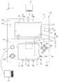
- FIG. 1is a front view of a game apparatus 10 in its opened state
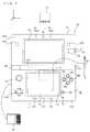
- FIG. 2is a right side view of the game apparatus 10 in its opened state
- FIG. 3shows a left side view, a front view, a right side view, and a rear view of the game apparatus 10 in its closed state;
- FIG. 4is a non-limiting exemplary block diagram illustrating an internal configuration of the game apparatus 10 ;
- FIG. 5shows a non-limiting example of an image displayed on an upper LCD 22 when a marker 61 which is placed in advance in the real space is shot by an outer imaging section 23 , while game processing according to an illustrative embodiment is being executed;
- FIG. 6shows a non-limiting exemplary scene in which a plane on which the marker 61 is placed is heaving when the user has performed a predetermined operation
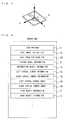
- FIG. 7shows a non-limiting example of the definition of a marker coordinate system
- FIG. 8shows a non-limiting exemplary memory map of a RAM of the game apparatus 10 ;
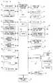
- FIG. 9is a non-limiting exemplary main flowchart showing the details of the game processing according to the embodiment.
- FIG. 10is a non-limiting exemplary flowchart showing the details of marker recognition processing (step S 3 );
- FIG. 11is a non-limiting exemplary flowchart showing the details of left virtual camera image generation processing (step S 7 );
- FIG. 12shows a non-limiting exemplary position relationship between the marker 61 and an outer imaging section (left) 23 a;
- FIG. 13shows a virtual model 55 ;
- FIG. 14shows a deformation object 56
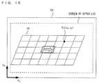
- FIG. 15shows texture coordinates T(i) of a vertex P(i);
- FIG. 16is a non-limiting exemplary diagram conceptually illustrating processing of step S 35 , and shows cutting of an image in a left texture area from a real image for a left eye 72 L;
- FIG. 17is a non-limiting exemplary diagram conceptually illustrating the processing of step S 35 , and shows a non-limiting example of application of a cut image ai in the left texture area shown in FIG. 94 to the deformation object 56 ;
- FIG. 18shows a non-limiting example of cutting of an image in a right texture area from a real image for a right eye 72 R;
- FIG. 19shows a non-limiting example of application of a cut image bi in the right texture area shown in FIG. 96 to the deformation object 56 ;
- FIG. 20shows a non-limiting exemplary case where a fish object 52 is masked by a mask object 57 ;
- FIG. 21is a non-limiting exemplary diagram illustrating pixel information being lost when a right virtual camera image is generated by using the image in the left texture area.
- FIG. 1 to FIG. 3are each a plan view of an outer appearance of a game apparatus 10 .
- the game apparatus 10is a hand-held game apparatus, and is configured to be foldable as shown in FIG. 1 to FIG. 3 .
- FIG. 1 and FIG. 2show the game apparatus 10 in an opened state
- FIG. 3shows the game apparatus 10 in a closed state.
- FIG. 1is a front view of the game apparatus 10 in the opened state
- FIG. 2is a right side view of the game apparatus 10 in the opened state.
- the game apparatus 10is able to shoot an image by means of an imaging section, display the shot image on a screen, and store data of the shot image.
- the game apparatus 10can execute a game program which is stored in an exchangeable memory card or a game program which is received from a server or another game apparatus, and can display, on the screen, an image generated by computer graphics processing, such as an image shot by a virtual camera set in a virtual space, for example.
- the game apparatus 10includes a lower housing 11 and an upper housing 21 as shown in FIG. 1 to FIG. 3 .
- the lower housing 11 and the upper housing 21are connected to each other so as to be openable and closable (foldable).
- the lower housing 11 and the upper housing 21are each formed in a horizontally long plate-like rectangular shape, and are connected to each other at long side portions thereof so as to be pivotable with respect to each other.
- projections 11 A each of which projects in a direction orthogonal to an inner side surface (main surface) 11 B of the lower housing 11are provided at the upper long side portion of the lower housing 11
- a projection 21 A which projects from the lower side surface of the upper housing 21 in a direction orthogonal to the lower side surface of the upper housing 21is provided at the lower long side portion of the upper housing 21 . Since the projections 11 A of the lower housing 11 and the projection 21 A of the upper housing 21 are connected to each other, the lower housing 11 and the upper housing 21 are foldably connected to each other.
- a structure of the lower housing 11will be described.
- a lower LCD (Liquid Crystal Display) 12in the lower housing 11 , a touch panel 13 , operation buttons 14 A to 14 L ( FIG. 1 , FIG. 3 ), an analog stick 15 , an LED 16 A and an LED 16 B, an insertion opening 17 , and a microphone hole 18 are provided.
- these componentswill be described in detail.
- the lower LCD 12is accommodated in the lower housing 11 .
- the lower LCD 12has a horizontally long shape, and is located such that a long side direction thereof corresponds to a long side direction of the lower housing 11 .
- the lower LCD 12is positioned at the center of the lower housing 11 .
- the lower LCD 12is provided on the inner side surface (main surface) of the lower housing 11 , and a screen of the lower LCD 12 is exposed at an opening of the lower housing 11 .
- the number of pixels of the lower LCD 12may be, for example, 256 dots ⁇ 192 dots (the longitudinal line ⁇ the vertical line).
- the lower LCD 12is a display device for displaying an image in a planar manner (not in a stereoscopically visible manner), which is different from the upper LCD 22 as described below.
- an LCDis used as a display device in the present embodiment, any other display device such as a display device using an EL (Electro Luminescence), or the like may be used.
- a display device having any resolutionmay be used as the lower LCD 12 .
- the game apparatus 10includes the touch panel 13 as an input device.
- the touch panel 13is mounted on the screen of the lower LCD 12 .
- the touch panel 13may be, but is not limited to, a resistive film type touch panel.
- a touch panel of any type such as electrostatic capacitance typemay be used.
- the touch panel 13has the same resolution (detection accuracy) as that of the lower LCD 12 .
- the resolution of the touch panel 13 and the resolution of the lower LCD 12may not necessarily be the same.
- the insertion opening 17(indicated by dashed line in FIG. 1 and FIG. 3( d )) is provided on the upper side surface of the lower housing 11 .
- the insertion opening 17is used for accommodating a touch pen 28 which is used for performing an operation on the touch panel 13 .
- a touch pen 28which is used for performing an operation on the touch panel 13 .
- an input on the touch panel 13is usually made by using the touch pen 28
- a finger of a usermay be used for making an input on the touch panel 13 , besides the touch pen 28 .
- the operation buttons 14 A to 14 Lare each an input device for making a predetermined input. As shown in FIG. 1 , among operation buttons 14 A to 14 L, a cross button 14 A (a direction input button 14 A), an a-button 14 B, a b-button 14 C, an x-button 14 D, a y-button 14 E, a power button 14 F, a selection button 14 J, a HOME button 14 K, and a start button 14 L are provided on the inner side surface (main surface) of the lower housing 11 .
- the cross button 14 Ais cross-shaped, and includes buttons for indicating an upward, a downward, a leftward, or a rightward direction.
- the button 14 B, button 14 C, button 14 D, and button 14 Eare positioned so as to form a cross shape.
- the buttons 14 A to 14 E, the selection button 14 J, the HOME button 14 K, and the start button 14 Lare assigned functions, respectively, in accordance with a program executed by the game apparatus 10 , as necessary.
- the cross button 14 Ais used for selection operation and the like, and the operation buttons 14 B to 14 E are used for, for example, determination operation and cancellation operation.
- the power button 14 Fis used for powering the game apparatus 10 on/off.
- the analog stick 15is a device for indicating a direction, and is provided to the left of the lower LCD 12 in an upper portion of the inner side surface of the lower housing 11 .
- the cross button 14 Ais provided to the left of the lower LCD 12 in the lower portion of the lower housing 11 . That is, the analog stick 15 is provided above the cross button 14 A.
- the analog stick 15 and the cross button 14 Aare positioned so as to be operated by a thumb of a left hand with which the lower housing is held.
- the analog stick 15is provided in the upper area, and thus the analog stick 15 is positioned such that a thumb of a left hand with which the lower housing 11 is held is naturally positioned on the position of the analog stick 15 , and the cross button 14 A is positioned such that the thumb of the left hand is positioned on the position of the cross button 14 A when the thumb of the left hand is slightly moved downward from the analog stick 15 .
- the analog stick 15has a top, corresponding to a key, which slides parallel to the inner side surface of the lower housing 11 .
- the analog stick 15acts in accordance with a program executed by the game apparatus 10 .
- the analog stick 15acts as an input device for moving the predetermined object in the 3-dimensional virtual space.
- the predetermined objectis moved in a direction in which the top corresponding to the key of the analog stick 15 slides.
- a component which enables an analog input by being tilted by a predetermined amountin any direction, such as the upward, the downward, the rightward, the leftward, or the diagonal direction, may be used.
- buttonsthat is, the a-button 14 B, the b-button 14 C, the x-button 14 D, and the y-button 14 E, which are positioned so as to form a cross shape, are positioned such that a thumb of a right hand with which the lower housing 11 is held is naturally positioned on the positions of the four buttons. Further, the four buttons and the analog stick 15 sandwich the lower LCD 12 , so as to be bilaterally symmetrical in position with respect to each other. Thus, depending on a game program, for example, a left-handed person can make a direction instruction input by using these four buttons.
- the microphone hole 18is provided on the inner side surface of the lower housing 11 .
- a microphone(see FIG. 4 ) is provided as a sound input device described below, and the microphone detects for a sound from the outside of the game apparatus 10 .
- FIG. 3( a )is a left side view of the game apparatus 10 in the closed state.
- FIG. 3( b )is a front view of the game apparatus 10 in the closed state.
- FIG. 3( c )is a right side view of the game apparatus 10 in the closed state.
- FIG. 3( d )is a rear view of the game apparatus 10 in the closed state.
- an L button 14 G and an R button 14 Hare provided on the upper side surface of the lower housing 11 .
- the L button 14 Gis positioned on the left end portion of the upper side surface of the lower housing 11 and the R button 14 H is positioned on the right end portion of the upper side surface of the lower housing 11 .
- a sound volume button 14 Iis provided on the left side surface of the lower housing 11 .
- the sound volume button 14 Iis used for adjusting a sound volume of a speaker of the game apparatus 10 .
- a cover section 11 Cis provided on the left side surface of the lower housing 11 so as to be openable and closable.
- a connector(not shown) is provided inside the cover section 11 C for electrically connecting between the game apparatus 10 and an external data storage memory 45 .
- the external data storage memory 45is detachably connected to the connector.
- the external data storage memory 45is used for, for example, recording (storing) data of an image shot by the game apparatus 10 .
- the connector and the cover section 11 Cmay be provided on the right side surface of the lower housing 11 .
- an insertion opening 11 D through which an external memory 44 having a game program stored therein is insertedis provided on the upper side surface of the lower housing 11 .
- a connector(not shown) for electrically connecting between the game apparatus 10 and the external memory 44 in a detachable manner is provided inside the insertion opening 11 D.
- a predetermined game programis executed by connecting the external memory 44 to the game apparatus 10 .
- the connector and the insertion opening 11 Dmay be provided on another side surface (for example, the right side surface) of the lower housing 11 .
- a first LED 16 A for notifying a user of an ON/OFF state of a power supply of the game apparatus 10is provided on the lower side surface of the lower housing 11
- a second LED 16 B for notifying a user of an establishment state of a wireless communication of the game apparatus 10is provided on the right side surface of the lower housing 11 .
- the game apparatus 10can make wireless communication with other devices, and the second LED 16 B is lit up when the wireless communication is established.
- the game apparatus 10has a function of connecting to a wireless LAN in a method based on, for example, IEEE802.11.b/g standard.
- a wireless switch 19 for enabling/disabling the function of the wireless communicationis provided on the right side surface of the lower housing 11 (see FIG. 3( c )).
- a rechargeable battery (not shown) acting as a power supply for the game apparatus 10is accommodated in the lower housing 11 , and the battery can be charged through a terminal provided on a side surface (for example, the upper side surface) of the lower housing 11 .
- an upper LCD (Liquid Crystal Display) 22As shown in FIG. 1 to FIG. 3 , in the upper housing 21 , an upper LCD (Liquid Crystal Display) 22 , an outer imaging section 23 (an outer imaging section (left) 23 a and an outer imaging section (right) 23 b ), an inner imaging section 24 , a 3D adjustment switch 25 , and a 3D indicator 26 are provided.
- an upper LCDLiquid Crystal Display
- an outer imaging section 23an outer imaging section (left) 23 a and an outer imaging section (right) 23 b )
- an inner imaging section 24As shown in FIG. 1 to FIG. 3 , theses components will be described in detail.
- the upper LCD 22is accommodated in the upper housing 21 .
- the upper LCD 22has a horizontally long shape, and is located such that a long side direction thereof corresponds to a long side direction of the upper housing 21 .
- the upper LCD 22is positioned at the center of the upper housing 21 .
- the area of a screen of the upper LCD 22is set so as to be greater than the area of the screen of the lower LCD 12 .
- the screen of the upper LCD 22is horizontally elongated as compared to the screen of the lower LCD 12 .
- a rate of the horizontal width in the aspect ratio of the screen of the upper LCD 22is set so as to be greater than a rate of the horizontal width in the aspect ratio of the screen of the lower LCD 12 .
- the screen of the upper LCD 22is provided on the inner side surface (main surface) 21 B of the upper housing 21 , and the screen of the upper LCD 22 is exposed at an opening of the upper housing 21 . Further, as shown in FIG. 2 , the inner side surface of the upper housing 21 is covered with a transparent screen cover 27 .
- the screen cover 27protects the screen of the upper LCD 22 , and integrates the upper LCD 22 and the inner side surface of the upper housing 21 with each other, thereby achieving unity.
- the number of pixels of the upper LCD 22may be, for example, 640 dots ⁇ 200 dots (the horizontal line ⁇ the vertical line).
- the upper LCD 22is an LCD, a display device using an EL (Electro Luminescence), or the like may be used. In addition, a display device having any resolution may be used as the upper LCD 22 .
- the upper LCD 22is a display device capable of displaying a stereoscopically visible image (also referred to as a stereoscopic view image or a stereoscopic image). Further, in the present embodiment, an image for a left eye and an image for a right eye are displayed by using substantially the same display area.
- the upper LCD 22may be a display device using a method in which the image for a left eye and the image for a right eye are alternately displayed in the horizontal direction in predetermined units (for example, every other line). Alternatively, a display device using a method in which the image for a left eye and the image for a right eye are alternately displayed for a predetermined time period may be used.
- the upper LCD 22is a display device capable of displaying an image which is stereoscopically visible with naked eyes.
- a lenticular lens type display device or a parallax barrier type display deviceis used which enables the image for a left eye and the image for a right eye, which are alternately displayed in the horizontal direction, to be separately viewed by the left eye and the right eye, respectively.
- the upper LCD 22 of a parallax barrier typeis used. The upper LCD 22 displays, by using the image for a right eye and the image for a left eye, an image (a stereoscopic image) which is stereoscopically visible with naked eyes.
- the upper LCD 22allows a user to view the image for a left eye with her/his left eye, and the image for a right eye with her/his right eye by utilizing a parallax barrier, so that a stereoscopic image (a stereoscopically visible image) exerting a stereoscopic effect for a user can be displayed. Further, the upper LCD 22 may disable the parallax barrier. When the parallax barrier is disabled, an image can be displayed in a planar manner (it is possible to display a planar visible image which is different from a stereoscopically visible image as described above. Specifically, a display mode is used in which the same displayed image is viewed with a left eye and a right eye).
- the upper LCD 22is a display device capable of switching between a stereoscopic display mode for displaying a stereoscopically visible image and a planar display mode (for displaying a planar visible image) for displaying an image in a planar manner.
- the switching of the display modeis performed by the 3D adjustment switch 25 described later.
- the imaging directions of the outer imaging section (left) 23 a and the outer imaging section (right) 23 bare each the same as the outward normal direction of the outer side surface 21 D. Further, these imaging sections are each designed so as to be positioned in a direction which is opposite to the normal direction of the display surface (inner side surface) of the upper LCD 22 by 180 degrees. Specifically, the imaging direction of the outer imaging section (left) 23 a and the imaging direction of the outer imaging section (right) 23 b are parallel to each other.
- the outer imaging section (left) 23 a and the outer imaging section (right) 23 bcan be used as a stereo camera depending on a program executed by the game apparatus 10 . Further, depending on a program, when any one of the two outer imaging sections ( 23 a and 23 b ) is used alone, the outer imaging section 23 may be used as a non-stereo camera. Further, depending on a program, images shot by the two outer imaging sections ( 23 a and 23 b ) may be combined with each other or may compensate for each other, thereby enabling imaging using an extended imaging range.
- the outer imaging section 23is structured so as to include two imaging sections, that is, the outer imaging section (left) 23 a and the outer imaging section (right) 23 b .
- Each of the outer imaging section (left) 23 a and the outer imaging section (right) 23 bincludes an imaging device, such as a CCD image sensor or a CMOS image sensor, having a common predetermined resolution, and a lens.
- the lensmay have a zooming mechanism.
- the outer imaging section (left) 23 a and the outer imaging section (right) 23 b forming the outer imaging section 23are aligned so as to be parallel to the horizontal direction of the screen of the upper LCD 22 .
- the outer imaging section (left) 23 a and the outer imaging section (right) 23 bare positioned such that a straight line connecting between the two imaging sections is parallel to the horizontal direction of the screen of the upper LCD 22 .
- Reference numerals 23 a and 23 bwhich are indicated as dashed lines in FIG.
- FIG. 1represent the outer imaging section (left) 23 a and the outer imaging section (right) 23 b , respectively, which are positioned on the outer side surface reverse of the inner side surface of the upper housing 21 .
- the outer imaging section (left) 23 ais positioned to the left of the upper LCD 22 and the outer imaging section (right) 23 b is positioned to the right of the upper LCD 22 .
- the outer imaging section (left) 23 ashoots an image for a left eye, which is viewed by a left eye of a user
- the outer imaging section (right) 23 bshoots an image for a right eye, which is viewed by a right eye of the user.
- a distance between the outer imaging section (left) 23 a and the outer imaging section (right) 23 bis set so as to be approximately the same as a distance between both eyes of a person, that is, may be set so as to be within a range from 30 mm to 70 mm, for example.
- the distance between the outer imaging section (left) 23 a and the outer imaging section (right) 23 bis not limited to a distance within the range described above.
- the outer imaging section (left) 23 a and the outer imaging section (right) 23 bare secured to the housing, and the imaging directions thereof cannot be changed.
- the outer imaging section (left) 23 a and the outer imaging section (right) 23 bare positioned to the left and to the right, respectively, of the upper LCD 22 (on the left side and the right side, respectively, of the upper housing 21 ) so as to be horizontally symmetrical with respect to the center of the upper LCD 22 .
- the outer imaging section (left) 23 a and the outer imaging section (right) 23 bare positioned so as to be symmetrical with respect to a line which divides the upper LCD 22 into two equal parts, that is, the left part and the right part.
- the outer imaging section (left) 23 a and the outer imaging section (right) 23 bare positioned at positions which are reverse of positions above the upper edge of the screen of the upper LCD 22 and which are on the upper portion of the upper housing 21 in an opened state. Specifically, when the upper LCD 22 is projected on the outer side surface of the upper housing 21 , the outer imaging section (left) 23 a and the outer imaging section (right) 23 b are positioned, on the outer side surface of the upper housing 21 , at a position above the upper edge of the screen of the upper LCD 22 having been projected.
- the two imaging sections ( 23 a and 23 b ) of the outer imaging section 23are positioned to the left and the right of the upper LCD 22 so as to be horizontally symmetrical with respect to the center of the upper LCD 22 . Therefore, when a user views the upper LCD 22 from the front thereof, the imaging direction of the outer imaging section 23 can be the same as the direction of the line of sight of the user. Further, the outer imaging section 23 is positioned at a position reverse of a position above the upper edge of the screen of the upper LCD 22 . Therefore, the outer imaging section 23 and the upper LCD 22 do not interfere with each other inside the upper housing 21 . Therefore, the upper housing 21 may have a reduced thickness as compared to a case where the outer imaging section 23 is positioned on a position reverse of a position of the screen of the upper LCD 22 .
- the inner imaging section 24is positioned on the inner side surface (main surface) 21 B of the upper housing 21 , and acts as an imaging section which has an imaging direction which is the same direction as the inward normal direction of the inner side surface.
- the inner imaging section 24includes an imaging device, such as a CCD image sensor and a CMOS image sensor, having a predetermined resolution, and a lens.
- the lensmay have a zooming mechanism.
- the inner imaging section 24is positioned, on the upper portion of the upper housing 21 , above the upper edge of the screen of the upper LCD 22 . Further, in this state, the inner imaging section 24 is positioned at the horizontal center of the upper housing 21 (on a line which separates the upper housing 21 (the screen of the upper LCD 22 ) into two equal parts, that is, the left part and the right part). Specifically, as shown in FIG. 1 and FIG.
- the inner imaging section 24is positioned on the inner side surface of the upper housing 21 at a position reverse of the middle position between the left and the right imaging sections (the outer imaging section (left) 23 a and the outer imaging section (right) 23 b ) of the outer imaging section 23 .
- the inner imaging section 24is positioned at the middle position between the left and the right imaging sections having been projected.
- the dashed line 24 indicated in FIG. 3( b )represents the inner imaging section 24 positioned on the inner side surface of the upper housing 21 .
- the inner imaging section 24is used for shooting an image in the direction opposite to that of the outer imaging section 23 .
- the inner imaging section 24is positioned on the inner side surface of the upper housing 21 at a position reverse of the middle position between the left and the right imaging sections of the outer imaging section 23 .
- the inner imaging section 24can shoot an image of a face of the user from the front thereof.
- the left and the right imaging sections of the outer imaging section 23do not interfere with the inner imaging section 24 inside the upper housing 21 , thereby enabling reduction of the thickness of the upper housing 21 .
- the 3D adjustment switch 25is a slide switch, and is used for switching a display mode of the upper LCD 22 as described above. Further, the 3D adjustment switch 25 is used for adjusting the stereoscopic effect of a stereoscopically visible image (stereoscopic image) which is displayed on the upper LCD 22 . As shown in FIG. 1 to FIG. 3 , the 3D adjustment switch 25 is provided at the end portions of the inner side surface and the right side surface of the upper housing 21 , and is positioned at a position at which the 3D adjustment switch 25 is visible to a user when the user views the upper LCD 22 from the front thereof. Further, an operation section of the 3D adjustment switch 25 projects on the inner side surface and the right side surface, and can be viewed and operated from both sides. All the switches other than the 3D adjustment switch 25 are provided on the lower housing 11 .
- the 3D adjustment switch 25is provided so as to be visible from the front surface and the right side surface of the upper housing 21 as shown in FIG. 1 and FIG. 2 .
- a slider 25 a of the 3D adjustment switch 25is slidable to any position in a predetermined direction (the height direction).
- a display mode of the upper LCD 22may be determined or feeling of stereoscopic viewing may be adjusted, in accordance with the position of the slider 25 a .
- a cameras distance between virtual cameras (virtual stereo cameras) described latermay be set in accordance with the position of the slider 25 a of the 3D adjustment switch 25 .
- the position relationship between an image for a left eye shot by a left virtual camera of the virtual stereo cameras, and an image for a right eye shot by a right virtual camera of the virtual stereo camerasmay be adjusted in accordance with the position of the slider 25 a .
- the slider 25 a of the 3D adjustment switch 25is positioned at the uppermost point (in the upward direction in FIG. 1 and FIG. 2 )
- the difference, in the lateral direction(the longitudinal direction of the screen of the upper LCD 22 , the right-left direction in FIG. 1 ) between the positions of the image for a left eye and the image for a right eye is set at the upper limit value.
- the parallax between the two imagesincreases. Therefore, when the user views the two images displayed on the upper LCD 22 via the parallax barrier, the images appear to protrude toward the user from the screen of the upper LCD 22 . In this way, the parallax between the two images may be adjusted by using the 3D adjustment switch 25 .
- the 3D indicator 26indicates whether or not the upper LCD 22 is in the stereoscopic display mode.
- the 3D indicator 26is implemented as a LED, and is lit up when the stereoscopic display mode of the upper LCD 22 is enabled.
- the 3D indicator 26may be lit up only when the program processing for displaying a stereoscopically visible image is performed in a state where the upper LCD 22 is in the stereoscopic display mode.
- the 3D indicator 26is positioned near the screen of the upper LCD 22 on the inner side surface of the upper housing 21 . Therefore, when a user views the screen of the upper LCD 22 from the front thereof, the user can easily view the 3D indicator 26 . Therefore, also when a user is viewing the screen of the upper LCD 22 , the user can easily recognize the display mode of the upper LCD 22 .
- a speaker hole 21 Eis provided on the inner side surface of the upper housing 21 . A sound is outputted through the speaker hole 21 E from a speaker 43 described later.
- FIG. 4is a block diagram illustrating an internal configuration of the game apparatus 10 .
- the game apparatus 10includes, in addition to the components described above, electronic components such as an information processing section 31 , a main memory 32 , an external memory interface (external memory UF) 33 , an external data storage memory UF 34 , an internal data storage memory 35 , a wireless communication module 36 , a local communication module 37 , a real-time clock (RTC) 38 , an acceleration sensor 39 , a power supply circuit 40 , an interface circuit (I/F circuit) 41 , and the like.
- These electronic componentsare mounted on an electronic circuit substrate, and accommodated in the lower housing 11 (or the upper housing 21 ).
- the information processing section 31is information processing means which includes a CPU (Central Processing Unit) 311 for executing a predetermined program, a GPU (Graphics Processing Unit) 312 for performing image processing, and the like.
- a predetermined programis stored in a memory (for example, the external memory 44 connected to the external memory I/F 33 or the internal data storage memory 35 ) inside the game apparatus 10 .
- the CPU 311 of the information processing section 31executes an image processing ( FIG. 12 ) described later by executing the predetermined program.
- the program executed by the CPU 311 of the information processing section 31may be acquired from another device through communication with the other device.
- the information processing section 31further includes a VRAM (Video RAM) 313 .
- the GPU 312 of the information processing section 31generates an image in accordance with an instruction from the CPU 311 of the information processing section 31 , and renders the image in the VRAM 313 .
- the GPU 312 of the information processing section 31outputs the image rendered in the VRAM 313 , to the upper LCD 22 and/or the lower LCD 12 , and the image is displayed on the upper LCD 22 and/or the lower LCD 12 .
- the main memory 32 , the external memory I/F 33 , the external data storage memory I/F 34 , and the internal data storage memory 35are connected to the information processing section 31 .
- the external memory I/F 33is an interface for detachably connecting to the external memory 44 .
- the external data storage memory I/F 34is an interface for detachably connecting to the external data storage memory 45 .
- the main memory 32is volatile storage means used as a work area and a buffer area for (the CPU 311 of) the information processing section 31 . That is, the main memory 32 temporarily stores various types of data used for the image processing, and temporarily stores a program acquired from the outside (the external memory 44 , another device, or the like), for example. In the present embodiment, for example, a PSRAM (Pseudo-SRAM) is used as the main memory 32 .
- a PSRAMPseudo-SRAM
- the external memory 44is nonvolatile storage means for storing a program executed by the information processing section 31 .
- the external memory 44is implemented as, for example, a read-only semiconductor memory.
- the information processing section 31can load a program stored in the external memory 44 .
- a predetermined processingis performed by the program loaded by the information processing section 31 being executed.
- the external data storage memory 45is implemented as a non-volatile readable and writable memory (for example, a NAND flash memory), and is used for storing predetermined data. For example, images shot by the outer imaging section 23 and/or images shot by another device are stored in the external data storage memory 45 .
- the information processing section 31loads an image stored in the external data storage memory 45 , and the image can be displayed on the upper LCD 22 and/or the lower LCD 12 .
- the internal data storage memory 35is implemented as a non-volatile readable and writable memory (for example, a NAND flash memory), and is used for storing predetermined data. For example, data and/or programs downloaded through the wireless communication module 36 by wireless communication is stored in the internal data storage memory 35 .
- a non-volatile readable and writable memoryfor example, a NAND flash memory
- the wireless communication module 36has a function of connecting to a wireless LAN by using a method based on, for example, IEEE 802.11.b/g standard.
- the local communication module 37has a function of performing wireless communication with the same type of game apparatus in a predetermined communication method (for example, infrared communication).
- the wireless communication module 36 and the local communication module 37are connected to the information processing section 31 .
- the information processing section 31can perform data transmission to and data reception from another device via the Internet by using the wireless communication module 36 , and can perform data transmission to and data reception from the same type of another game apparatus by using the local communication module 37 .
- the acceleration sensor 39is connected to the information processing section 31 .
- the acceleration sensor 39detects magnitudes of accelerations (linear accelerations) in the directions of the straight lines along the three axial (xyz axial) directions, respectively.
- the acceleration sensor 39is provided inside the lower housing 11 .
- the long side direction of the lower housing 11is defined as x axial direction
- the short side direction of the lower housing 11is defined as y axial direction
- the direction orthogonal to the inner side surface (main surface) of the lower housing 11is defined as z axial direction, thereby detecting magnitudes of the linear accelerations for the respective axes.
- the acceleration sensor 39is, for example, an electrostatic capacitance type acceleration sensor.
- the acceleration sensor 39may be an acceleration sensor for detecting a magnitude of an acceleration for one axial direction or two-axial directions.
- the information processing section 31can receive data (acceleration data) representing accelerations detected by the acceleration sensor 39 , and detect an orientation and a motion of the game apparatus 10 . In the present embodiment, the information processing section 31 the orientation (inclination) of the game apparatus 10 , based on the acceleration detected by the acceleration sensor 39 .
- the RTC 38 and the power supply circuit 40are connected to the information processing section 31 .
- the RTC 38counts time, and outputs the time to the information processing section 31 .
- the information processing section 31calculates a current time (date) based on the time counted by the RTC 38 .
- the power supply circuit 40controls power from the power supply (the rechargeable battery accommodated in the lower housing 11 as described above) of the game apparatus 10 , and supplies power to each component of the game apparatus 10 .
- the I/F circuit 41is connected to the information processing section 31 .
- the microphone 42 and the speaker 43are connected to the I/F circuit 41 .
- the speaker 43is connected to the I/F circuit 41 through an amplifier which is not shown.
- the microphone 42detects a voice from a user, and outputs a sound signal to the I/F circuit 41 .
- the amplifieramplifies a sound signal outputted from the I/F circuit 41 , and a sound is outputted from the speaker 43 .
- the touch panel 13is connected to the I/F circuit 41 .
- the I/F circuit 41includes a sound control circuit for controlling the microphone 42 and the speaker 43 (amplifier), and a touch panel control circuit for controlling the touch panel.
- the sound control circuitperforms A/D conversion and D/A conversion on the sound signal, and converts the sound signal to a predetermined form of sound data, for example.
- the touch panel control circuitgenerates a predetermined form of touch position data based on a signal outputted from the touch panel 13 , and outputs the touch position data to the information processing section 31 .
- the touch position datarepresents a coordinate of a position, on an input surface of the touch panel 13 , on which an input is made.
- the touch panel control circuitreads a signal outputted from the touch panel 13 , and generates the touch position data every predetermined time.
- the information processing section 31acquires the touch position data, to recognize a position on which an input is made on the touch panel 13 .
- the operation button 14includes the operation buttons 14 A to 14 L described above, and is connected to the information processing section 31 .
- Operation data representing an input state of each of the operation buttons 14 A to 14 Iis outputted from the operation button 14 to the information processing section 31 , and the input state indicates whether or not each of the operation buttons 14 A to 14 I has been pressed.
- the information processing section 31acquires the operation data from the operation button 14 to perform processing in accordance with the input on the operation button 14 .
- the lower LCD 12 and the upper LCD 22are connected to the information processing section 31 .
- the lower LCD 12 and the upper LCD 22each display an image in accordance with an instruction from (the GPU 312 of) the information processing section 31 .
- the information processing section 31is connected to an LCD controller (not shown) of the upper LCD 22 , and causes the LCD controller to set the parallax barrier to ON or OFF.
- the parallax barrieris set to ON in the upper LCD 22
- an image for a right eye and an image for a left eye, which are stored in the VRAM 313 of the information processing section 31are outputted to the upper LCD 22 .
- the LCD controlleralternately repeats reading of pixel data of the image for a right eye for one line in the vertical direction, and reading of pixel data of the image for a left eye for one line in the vertical direction, thereby reading, from the VRAM 313 , the image for a right eye and the image for a left eye.
- an image to be displayedis divided into the images for a right eye and the images for a left eye each of which is a rectangle-shaped image having one line of pixels aligned in the vertical direction, and an image, in which the rectangle-shaped image for the left eye which is obtained through the division, and the rectangle-shaped image for the right eye which is obtained through the division are alternately aligned, is displayed on the screen of the upper LCD 22 .
- a userviews the images through the parallax barrier in the upper LCD 22 , so that the image for the right eye is viewed by the user's right eye, and the image for the left eye is viewed by the user's left eye.
- the stereoscopically visible imageis displayed on the screen of the upper LCD 22 .
- the outer imaging section 23 and the inner imaging section 24are connected to the information processing section 31 .
- the outer imaging section 23 and the inner imaging section 24each shoot an image in accordance with an instruction from the information processing section 31 , and output data of the shot image to the information processing section 31 .
- the information processing section 31issues an instruction for shooting an image to one of the outer imaging section 23 or the inner imaging section 24
- the imaging section which receives the instruction for shooting an imageshoots an image and transmits data of the shot image to the information processing section 31 .
- a userselects the imaging section to be used through a touch operation using the touch panel 13 .
- the information processing section 31the CPU 311
- the information processing section 31instructs one of the outer imaging section 32 or the inner imaging section 24 to shoot an image.
- the 3D adjustment switch 25is connected to the information processing section 31 .
- the 3D adjustment switch 25transmits, to the information processing section 31 , an electrical signal in accordance with the position of the slider 25 a.
- the 3D indicator 26is connected to the information processing section 31 .
- the information processing section 31controls whether or not the 3D indicator 26 is to be lit up. In the present embodiment, the information processing section 31 lights up the 3D indicator 26 when the upper LCD 22 is in the stereoscopic display mode.
- the game apparatus 10has the internal configuration as described above.
- the angular velocity sensor 46is connected to the information processing section 31 .
- the angular velocity sensor 46detects angular velocities about the respective axes (x-axis, y-axis, and z-axis).
- the game apparatus 10can calculate the orientation of the game apparatus 10 in the real space, based on the angular velocities sequentially detected by the angular velocity sensor 46 .
- the game apparatus 10integrates the angular velocities about the respective axes detected by the angular velocity sensor 46 with respect to time, thereby calculating the rotation angles of the game apparatus 10 about the respective axes.
- FIG. 5shows an example of an image displayed on the upper LCD 22 when a marker 61 which is placed in advance in the real space is shot by the outer imaging section 23 , while the game according to the present embodiment is being executed.
- the marker 61is placed on the plane (a table or the like, which is not shown) in the real space, and in the shooting direction of the outer imaging section 23 .
- the marker 61is a piece of paper that is rectangular-shaped, and an arrow is drawn at the center of the marker 61 .
- the direction of the arrow drawn at the center of the marker 61is in parallel with the longitudinal sides of the marker 61 .
- the information processing section 31 (CPU 311 ) of the game apparatus 10performs image processing such as pattern matching for an image shot by the outer imaging section 23 , thereby detecting the marker 61 in the shot image.
- a fishing rod object 51 and a fish object 52are displayed on the upper LCD 22 .
- the fishing rod object 51 and the fish object 52are superimposed onto a real image (a shot image of the real space including the marker 61 and the background) shot by the outer imaging section 23 , and the resultant image is displayed on the upper LCD 22 .
- a message indicating that the marker 61 has not been detectedis displayed on the upper LCD 22 , and the fishing rod object 51 is not displayed.
- the outer imaging section 23shoots a real image for a left eye to be viewed by the left eye of the user, and a real image for a right eye to be viewed by the right eye of the user, and the two real images that have been shot are displayed on the upper LCD 22 . Therefore, the image displayed on the upper LCD 22 shown in FIG. 5 includes stereoscopically visible images (stereoscopic images).
- the image shown in FIG. 5is displayed on the upper LCD 22 , when the user performs a predetermined operation, the image indicating a scene in which an end portion of a fishing line of the fishing rod object 51 moves downward to come into contact with the plane on which the marker 61 is placed, and then the plane heaves, is displayed.
- the predetermined operationis, for example, an operation of moving the outer imaging section 23 of the game apparatus 10 toward the marker 61 , or an operation of inclining the game apparatus 10 so as to be in parallel with the plane on which the marker 61 is placed.
- FIG. 6shows a scene in which the plane on which the marker 61 is placed is heaving when the user has performed the predetermined operation.
- an image in which the plane in the real space on which the marker 61 is placed is heavingis displayed on the upper LCD 22 .
- a real image for a left eye and a real image for a right eyeare shot by the outer imaging section 23 , and the two real images that have been shot are deformed, whereby the plane in the real space stereoscopically heaving is displayed.
- FIG. 7shows a definition of the marker coordinate system.
- the marker coordinate systemis defined as an XYZ coordinate system whose origin is at the center of the marker 61 .
- a Z-axisis set in the same direction (forward direction) as the direction of the arrow of the marker 61
- an X-axisis set rightward (in the rightward direction) with respect to the direction of the arrow
- a Y-axisis set vertically and upward (in the upward direction) with respect to the marker 61 .
- a coordinate system (the marker coordinate system) in a virtual spaceis defined based on the marker 61 placed in the real space, thereby associating the virtual space with the real space.
- the fish object 52is set in the virtual space defined by the marker coordinate system. Therefore, when the position or the orientation of the game apparatus 10 (outer imaging section 23 ) is changed, a manner in which the fish object 52 is visible also changes. For example, when the user turns the game apparatus 10 90 degrees around the marker 61 (turns the game apparatus 10 90 degrees around the Y-axis), the fish object 52 is displayed so as to turn 90 degrees. Therefore, the user can feel as if the fish object 52 were present in the real space. It is noted that even if the position of the game apparatus 10 is changed, the fishing rod object 51 does not change (as the user holds the fishing rod object 51 , the position of the fishing rod object 51 in the virtual space changes in accordance with the position of the user in the real space).
- FIG. 8shows a memory map of the RAM of the game apparatus 10 . As shown in FIG.
- the RAMstores a game program 71 , a real image for a left eye 72 L, a real image for a right eye 72 R, virtual model information 73 , deformed object information 74 , left virtual camera information 75 L, right virtual camera information 75 R, a left virtual camera image 76 L, a right virtual camera image 76 R, fish object information 77 , mask object information 78 , and the like.
- the game program 71is a program for causing the information processing section 31 (CPU 311 ) to execute game processing shown in flowcharts described later.
- the real image for a left eye 72 Lis an image of the real space shot by the outer imaging section (left) 23 a.
- the real image for a right eye 72 Ris an image of the real space shot by the outer imaging section (right) 23 b.
- the virtual model information 73is information relevant to a virtual model 55 (see FIG. 13 ) described later.
- the points P included in the virtual model 55are represented by coordinate values in the marker coordinate system.
- the left virtual camera information 75 Lindicates the position and the orientation of a left virtual camera 53 a (see FIG. 12 ) in the virtual space. Specifically, the left virtual camera information 75 L is a matrix calculated based on the position and the orientation of the marker 61 in the real image for a left eye 72 L.
- the right virtual camera information 75 Rindicates the position and the orientation of a right virtual camera 53 b (see FIG. 12 ) in the virtual space. Specifically, the right virtual camera information 75 R is a matrix calculated based on the position and the orientation of the marker 61 in the real image for a right eye 72 R.
- the left virtual camera image 76 Lis an image obtained by the left virtual camera 53 a shooting the deformation object 56 .
- the right virtual camera image 76 Ris an image obtained by the right virtual camera 53 b shooting the deformation object 56 .
- the fish object information 77is information relevant to the fish object 52 placed in the virtual space, and indicates the position and the shape of the fish object 52 .
- the mask object information 78is information relevant to a mask object 57 (see FIG. 20 ) for masking the fish object 52 placed in the virtual space such that the fish object 52 is not visible from a predetermined direction.
- FIG. 9is a main flowchart showing the detail of the game processing according to the present embodiment.
- the information processing section 31(CPU 311 ) of the game apparatus 10 executes a boot program stored in a ROM, which is not shown, thereby initializing units such as the main memory 32 .
- a game program stored in a non-volatile memory(external memory 44 or the like, a computer-readable storage medium) is loaded onto a RAM (specifically, the main memory 32 ), and then the CPU 311 of the information processing section 31 starts to execute the game program.
- processing indicated by the flowchart in FIG. 9is executed by the information processing section 31 (the CPU 311 or the GPU 312 ).
- FIG. 9processing that is not directly relevant to the illustrative embodiment is omitted.
- FIG. 9will be described under the assumption that the marker 61 present in the real space has been shot by the outer imaging section 23 .
- a loop of processing from step S 2 to step S 10 in FIG. 9is repeated every frame (for example, 1/30 second or 1/60 second, which is referred to as a frame time).
- step S 1the information processing section 31 sets the virtual model 55 and the like. Specifically, the information processing section 31 sets the coordinates of the points P representing the virtual model 55 (in the marker coordinate system) at predetermined values, and stores the values in the RAM. Specifically, the points P are set on the XZ-plane in the marker coordinate system. In addition, the information processing section 31 sets the coordinates of the points Q representing the deformation object 56 at predetermined values (the same values as those of the points P), and stores the values in the RAM. In addition, the information processing section 31 sets the mask object 57 at an end portion of the virtual model 55 .
- FIG. 13shows the virtual model 55 .
- the virtual model 55is a polygon including n vertices P and having a planar shape, and is placed on the XZ-plane (the plane in the real space on which the marker 61 is placed) in the marker coordinate system (XYZ coordinate system).
- the information processing section 31executes processing of step S 2 .
- step S 2the information processing section 31 obtains a real camera image. Specifically, the information processing section 31 obtains the real image for a left eye 72 L shot by the outer imaging section (left) 23 a , and stores the obtained image in the RAM. In addition, the information processing section 31 obtains the real image for a right eye 72 R shot by the outer imaging section (right) 23 b , and stores the obtained image in the RAM. Next, the information processing section 31 executes processing of step S 3 .
- step S 3the information processing section 31 executes marker recognition processing.
- the marker recognition processingis processing of recognizing the marker 61 included in the real image for a left eye 72 L and the real image for a right eye 72 R obtained in step S 2 , and setting virtual cameras (the left virtual camera 53 a and the right virtual camera 53 b ). The details of the marker recognition processing in step S 3 will be described with reference to FIG. 10 .
- FIG. 10is a flowchart showing the details of the marker recognition processing (step S 3 ).
- step S 21the information processing section 31 calculates a position relationship between a real camera and a marker. Specifically, first, the information processing section 31 recognizes a marker included in the real image for a left eye 72 L by a pattern matching method or the like. Then, the information processing section 31 calculates the position relationship between the outer imaging section (left) 23 a , and the marker 61 present in the real space, based on the position, size, and shape of the marker in the real image for a left eye 72 L, the direction of an arrow in the marker, and the like.
- the position relationship between the outer imaging section (left) 23 a and the marker 61is the 3-dimensional position and the 3-dimensional orientation of one of the marker 61 and the outer imaging section (left) 23 a relative to the other one.
- FIG. 12shows the position relationship between the marker 61 and the outer imaging section (left) 23 a .
- the position relationshipis the relative position and relative orientation of the outer imaging section (left) 23 a with respect to the marker 61 .
- the information processing section 31calculates the position relationship between the outer imaging section (right) 23 b , and the marker 61 present in the real space, by using the real image for a right eye 72 R.
- a matrix indicating the relative position and relative orientation of the outer imaging section (left) 23 a with respect to the marker 61and a matrix indicating the relative position and relative orientation of the outer imaging section (right) 23 b with respect to the marker 61 , are calculated.
- step S 21the marker coordinate system is set based on a result of the recognition of the marker, and the position relationship between the marker 61 and the outer imaging section (left) 23 a are calculated (see FIG. 12 ).
- the origin of the marker coordinate systemis set at the center of the marker 61 .
- the Z-axis of the marker coordinate systemis set in parallel with the direction of the arrow of the marker 61 (that is, set in parallel with the longitudinal sides of the marker 61 ), and the X-axis of the marker coordinate system is set in the direction that is perpendicular and rightward with respect to the direction of the arrow (that is, set in parallel with the short sides of the marker 61 ).
- the Y-axisis set vertically and upward with respect to the marker 61 (that is, set upward in the normal direction of the rectangular marker 61 ).
- the marker coordinate systemis a coordinate system for defining the virtual space, and associating the virtual space with the real space. That is, the origin of the marker coordinate system coincides with the origin of the virtual space, and also with the center of the marker 61 in the real space.
- the matrix indicating the position and orientation of the outer imaging section (left) 23 ais a coordinate transform matrix that transforms coordinates represented in the marker coordinate system in the virtual space, into coordinates represented in an outer imaging section (left) coordinate system based on the position and the orientation of the outer imaging section (left) 23 a .
- step S 21the matrix indicating the position and orientation of the outer imaging section (left) 23 a is calculated based on the marker in the real image for a left eye 72 L, and a matrix indicating the position and orientation of the outer imaging section (right) 23 b is calculated based on the marker in the real image for a right eye 72 R.
- the outer imaging section (left) 23 a and the outer imaging section (right) 23 bare provided such that the shooting directions thereof are in parallel with each other and the outer imaging section (left) 23 a and the outer imaging section (right) 23 b do not rotate with respect to the shooting directions. That is, the orientation of the outer imaging section (left) 23 a and the orientation of the outer imaging section (right) 23 b always coincide with each other.
- the outer imaging section (left) 23 a and the outer imaging section (right) 23 bare provided being separated by a predetermined interval.
- the position and the orientation of the outer imaging section (left) 23 amay be calculated based on the real image for a left eye 72 L
- the position and the orientation of the outer imaging section (right) 23 bmay be calculated based on the real image for a right eye 72 R, thereby obtaining the error.
- the positions and the like of the outer imaging section (left) 23 a and the outer imaging section (right) 23 bmay be respectively calculated based on the real image for a left eye 72 L and the real image for a right eye 72 R during a certain time period, to calculate the error.
- the position and the orientation of the outer imaging section (left) 23 amay be calculated by using the real image for a left eye 72 L (or the real image for a right eye 72 R), and the position and the orientation of the outer imaging section (right) 23 b may be calculated based on the calculated error, and the calculated position and orientation of the outer imaging section (left) 23 a .
- the information processing section 31executes processing of step S 22 .
- step S 22the information processing section 31 determines the positions and the orientations of the left virtual camera and the right virtual camera.
- the positions and the orientations of the left virtual camera and the right virtual cameracoincide with the respective positions and orientations of the outer imaging section 23 . That is, the position and the orientation of the left virtual camera 53 a in the virtual space are set so as to coincide with the position and the orientation of the outer imaging section (left) 23 a (see FIG. 12 ).
- the position and the orientation of the right virtual camera 53 b in the virtual spaceare set so as to coincide with the position and the orientation of the outer imaging section (right) 23 b .
- the position and the orientation of the left virtual camera 53 aare represented by a matrix (left view matrix).
- a matrix indicating the position and the orientation of the outer imaging section (left) 23 a calculated in step S 21is stored as the left virtual camera information 75 L, in the RAM.
- the position and the orientation of the right virtual camera 53 bare represented by a matrix (right view matrix).
- a matrix indicating the position and the orientation of the outer imaging section (right) 23 b calculated in step S 21is stored as the right virtual camera information 75 R, in the RAM. It is noted that since the orientation of the outer imaging section (left) 23 a , and the orientation of the outer imaging section (right) 23 b always coincide with each other as described above, the orientation of the left virtual camera 53 a , and the orientation of the right virtual camera 53 b also coincide with each other.
- the information processing section 31ends the marker recognition processing.
- the information processing section 31executes processing of step S 4 , after step S 3 .
- step S 4the information processing section 31 sets the fish object 52 in the virtual space. Specifically, the information processing section 31 places the fish object 52 so as to be away from the virtual model 55 in the negative direction of the Y-axis. It is noted that the fish object 52 moves in the virtual space in accordance with a predetermined regularity. Next, the information processing section 31 executes processing of step S 5 .
- step S 5the information processing section 31 deforms a deformation object.
- FIG. 14shows the deformation object 56 .
- the deformation object 56is an object into which the virtual model 55 is deformed.
- the deformation object 56is generated when each of the points P of the virtual model 55 is moved in the upward or downward direction (positive or negative direction of the Y-axis) of the marker coordinate system.
- the information processing section 31determines a movement vector indicating the direction (positive or negative direction of the Y-axis) and the distance of a movement of each of the vertices Q, in accordance with the distance from a predetermined point to the vertex Q in the marker coordinate system. Then, the information processing section 31 adds the determined movement vectors to the respective current vertices Q, to move the vertices Q (update the coordinate values of the vertices Q and store the updated values in the RAM).
- step S 5the information processing section 31 moves only points of the deformation object 56 other than points on its end portions. That is, the coordinates of vertices present at the boundary (circumference) of the deformation object 56 shown in FIG. 14 do not change.
- the boundary of the deformation object 56is deformed and the resultant deformation object 56 is shot by a virtual camera in step S 7 or S 8 described later, an image obtained by superimposing the image shot by the virtual camera onto a real image with each other can be unnatural because the consistency at the boundary is not maintained.
- the imageis discontinuous at the boundary because an area outside and in the vicinity of the boundary of the deformation object 56 is not deformed while the boundary of the deformation object 56 is deformed, whereby the image provides a feeling of strangeness.
- the boundary of the deformation object 56since the boundary of the deformation object 56 is not deformed, the image is natural even at the boundary.
- step S 6the information processing section 31 executes processing of step S 6 .
- step S 6the information processing section 31 calculates the normal of each of the vertices Q.
- the information processing section 31calculates the normal vectors N(i) of the vertices Q(i) updated in step S 5 , and stores the normal vectors N(i) in the RAM.
- the information processing section 31executes processing of step S 7 .
- step S 7the information processing section 31 executes left virtual camera image generation processing.
- the details of the left virtual camera image generation processing of step S 7will be described with reference to FIG. 11 .
- FIG. 11is a flowchart showing the details of the left virtual camera image generation processing (step S 7 ).
- step S 31the information processing section 31 sets the variable i at 0 and stores the variable in the RAM.
- step S 32the information processing section 31 executes processing of step S 32 .
- step S 32the information processing section 31 calculates texture coordinates T(i) of the vertex P(i) of the virtual model 55 .
- the position (T(i)), in the real image for a left eye 72 L, of the vertex P(i) (in the marker coordinate system) of the virtual model 55 which is placed in the virtual spaceis calculated.
- FIG. 15shows the texture coordinates T(i) of the vertex P(i).
- the texture coordinates T(i)indicates a position in the real image for a left eye 72 L.
- the information processing section 31multiplies the vertex P(i) of the virtual model 55 represented in the marker coordinate system, by the left view matrix for the left virtual camera 53 a (a matrix calculated in step S 3 , the left virtual camera information 75 L), and by a projection matrix, thereby obtaining coordinates on the display of the upper LCD 22 (coordinates in a coordinate system whose origin is the lower left end of the screen of the upper LCD 22 ).
- the information processing section 31performs predetermined transform processing for the coordinates on the display, thereby calculating the coordinates T(i) (position in a coordinate system whose origin is the lower left end of the real image for a left eye 72 L) in the real image for a left eye 72 L.
- the size of the real image for a left eye 72 Lis larger than that of the upper LCD 22 . Therefore, the texture coordinates T are obtained by transforming the coordinates on the display into coordinates in the real image for a left eye 72 L (Tx-Ty coordinate system).
- the information processing section 31executes processing of step S 33 .
- step S 33the information processing section 31 increments the variable i.
- step S 34the information processing section 31 executes processing of step S 34 .
- step S 34the information processing section 31 determines whether or not i is equal to n. If the result of the determination is positive, the information processing section 31 executes processing of step S 35 . If the result of the determination is negative, the information processing section 31 executes the processing of step S 32 again.
- the texture coordinates T of all the vertices P of the virtual model 55are obtained by the processing from steps S 32 to S 34 being repeatedly executed.
- step S 35the information processing section 31 applies, as a texture, to the deformation object 56 , a part of the real image for a left eye 72 L in an area corresponding to each set of the texture coordinates, and then shoots the resultant by the left virtual camera.
- the information processing section 31sets the respective sets of texture coordinates T(i) for the vertices Q(i) of the deformation object 56 , maps textures thereto, and shoots the resultant by the left virtual camera 53 a .
- the information processing section 31stores the shot image as the left virtual camera image 76 L, in the RAM.
- step S 35corresponds to processing of cutting an image included in a left texture area corresponding to each set of the texture coordinates T calculated in the processing from steps S 32 to S 34 , from the real image for a left eye 72 L, and applying the image to the deformation object 56 .
- the outline of the processing of step S 35will be described with reference to FIG. 16 and FIG. 17 .
- FIG. 16is a diagram conceptually illustrating the processing of step S 35 , and shows cutting of an image in a left texture area from the real image for a left eye 72 L.
- an image aiparallelogram image including the texture coordinates T(i)
- the cut imageis applied to the deformation object 56 .
- FIG. 17is a diagram conceptually illustrating the processing of step S 35 , and shows application of the cut image ai in the left texture area shown in FIG. 16 to the deformation object 56 .
- the cut image ai in the left texture areahas been applied as a texture to the deformation object 56 , and then the resultant has been shot by the left virtual camera 53 a , the image ai is deformed (image ai′). In this manner, cut images in the respective left texture areas are applied to the deformation object 56 .
- the left virtual camera image 76 L generated in step S 35is an image obtained by deforming a part of the real image for a left eye 72 L in an area corresponding to the virtual model 55 (a part, in an area corresponding to the position and the contour of the virtual model 55 , of a rendered image of the virtual model 55 shot by the left virtual camera 53 a ).
- the virtual model 55is placed on the XZ-plane in the marker coordinate system (on the plane (table) in the real space on which the marker 61 is placed). Therefore, the left virtual camera image 76 L includes the XZ-plane (plane in the real space) that has been deformed.
- step S 35a shadow is applied in accordance with the shape of the deformation object 56 .
- step S 6the normal vectors of the vertices Q of the deformation object 56 have been calculated. Therefore, a shadow to be generated when the deformation object 56 is illuminated by a virtual light source can be calculated.
- step S 35the fish object 52 is also shot by the left virtual camera 53 a . Therefore, the left virtual camera image 76 L also includes an image of the fish object 52 .
- the information processing section 31After generating the left virtual camera image 76 L as described above, the information processing section 31 ends the left virtual camera image generation processing.
- step S 8the information processing section 31 executes processing of step S 8 .
- step S 8the information processing section 31 executes right virtual camera image generation processing.
- the right virtual camera image generation processing in step S 8similarly to the processing of step S 7 , an image in a texture area that is cut from the real image for a right eye 72 R is applied as a texture to the deformation object 56 , and the resultant is shot by the right virtual camera 53 b.
- step S 8the information processing section 31 calculates the texture coordinates T in the real image for a right eye 72 R. More specifically, the information processing section 31 multiplies each of the vertices P of the virtual model 55 represented in the marker coordinate system, by the right view matrix for the right virtual camera 53 b (a matrix calculated in step S 3 , the right virtual camera information 75 R), and by a projection matrix, thereby obtaining coordinates on the display of the upper LCD 22 , and obtaining the texture coordinates in the real image for a right eye 72 R.
- the information processing section 31sets the respective sets of texture coordinates for the vertices of the deformation object 56 , maps textures thereto, and shoots the resultant by the right virtual camera 53 b (an image in each of right texture areas is cut from the real image for a right eye 72 R, and the image is applied to the deformation object 56 ).
- the information processing section 31generates the right virtual camera image 76 R in this manner, and stores the right virtual camera image 76 R in the RAM. It is noted that as in step S 35 , the fish object 52 is also shot by the right virtual camera 53 b . Therefore, the right virtual camera image 76 R also includes an image of the fish object 52 .
- FIG. 18shows cutting of an image in a right texture area from the real image for a right eye 72 R. Since there is a parallax between the real image for a right eye 72 R and the real image for a left eye 72 L, the real image for a right eye 72 R and the real image for a left eye 72 L are different from each other. As shown in FIG. 16 and FIG. 18 , the position T(i) of each of the vertices P(i) of the virtual model in the real image for a right eye 72 R is different from the position T(i) of the corresponding vertex P(i) in the real image for a left eye 72 L.
- an image bi in a right texture area cut from the real image for a right eye 72 Rhas a shape different from the shape of an image ai in a left texture area cut from the real image for a left eye 72 L.
- the shape of the image bi in a right texture areais distorted more greatly than the shape of the image ai in a left texture area (in comparison of the image ai shown in FIG. 16 and the image bi shown in FIG. 18 , the shape of the image ai is closer to a square than the shape of the image bi).
- Images in the respective right texture areas cut from the real image for a right eye 72 Rare applied as textures to the deformation object 56 , and the resultant is shot by the right virtual camera 53 b .
- FIG. 19shows application of the cut image bi in the right texture area shown in FIG. 18 to the deformation object 56 .
- the image biis deformed (image bi′).
- cut images in the respective right texture areas cut from the real image for a right eye 72 Rare applied to the deformation object 56 .
- the right virtual camera image 76 R generated in step S 8includes the XZ-plane (plane in the real space) that has been deformed, as in the left virtual camera image 76 L generated in step S 7 .
- the right virtual camera image 76 R and the left virtual camera image 76 Lare different from each other, and there is a parallax therebetween.
- step S 8the information processing section 31 executes processing of step S 9 .
- step S 9the information processing section 31 superimposes a virtual camera image onto a real image to generate a superimposed image. Specifically, the information processing section 31 superimposes the left virtual camera image 76 L generated in step S 7 onto the real image for a left eye 72 L obtained in step S 2 to generate a left superimposed image. In addition, the information processing section 31 superimposes the right virtual camera image 76 R generated in step S 8 onto the real image for a right eye 72 R obtained in step S 2 to generate a right superimposed image. Next, the information processing section 31 executes processing of step S 10 .
- step S 10the information processing section 31 executes output processing.
- images providing a stereoscopic viewis displayed.
- the information processing section 31outputs two superimposed images generated in step S 9 to the upper LCD 22 .
- the left superimposed image displayed on the upper LCD 22is viewed by the left eye of the user via the parallax barrier, and the right superimposed image is viewed by the right eye of the user via the parallax barrier.
- the information processing section 31executes processing of step S 2 again.
- FIG. 20shows the case where the fish object 52 is masked by the mask object 57 , and shows the position relationship between the fish object 52 and a virtual camera when the virtual space is looked at from a direction parallel to the X-axis of the marker coordinate system.
- the mask object 57is a virtual object, having a planar shape, that is set at an end portion of the virtual model 55 (deformation object 56 ).
- the mask object 57hides the fish object 52 , and is not displayed on the upper LCD 22 . As shown in FIG.
- the mask object 57is not provided at the end portion of the deformation object 56 , when the fish object 52 is looked at from the position of the virtual camera Pc′, the fish object 52 might be visible in the backward direction in an area where the plane in the real space is not deformed as the deformation object 56 (that is, an area where a wave does not occur), and as a result, a displayed image might provide a feeling of strangeness.
- fish in wateris not visible owing to reflection of light when the surface of water is looked at from a direction with a low angle (when the surface of water is looked at not from the vertical direction but from a direction almost horizontal).
- the mask object 57is provided at the end portion of the virtual model 55 (deformation object 56 ), thereby causing the fish object 52 to be invisible from the virtual camera Pc′. That is, if the deformation object 56 is not present between a virtual camera and the fish object 52 (the deformation object 56 is not present on a line connecting a virtual camera and the fish object 52 ), the fish object 52 is hidden.
- the marker coordinate systemis set on the marker 61 .
- the virtual model 55which has a planar shape, is placed on the XZ-plane (plane on which the marker 61 is placed) in the marker coordinate system, and an area, in the real image for a left eye 72 L, that corresponds to the virtual model 55 is set as a left texture area (is cut as an image in a left texture area). Then, the image in the left texture area is applied as a texture to the deformation object 56 into which the virtual model 55 is deformed, and the resultant is shot by the left virtual camera, whereby the left virtual camera image is generated.
- an area, in the real image for a right eye 72 R, that corresponds to the virtual model 55is set as a right texture area (is cut as an image in a right texture area). Then, the image in the right texture area is applied as a texture to the deformation object 56 into which the virtual model 55 is deformed, and the resultant is shot by the right virtual camera, whereby the right virtual camera image is generated.
- an image including a plane in the real space that has been deformedcan be generated, and a scene in which the plane in the real space on which the marker 61 is placed heaves can be displayed as described above.
- the marker coordinate systemis set on the marker 61 placed in the real space, and a virtual camera is set in accordance with the position and the orientation of a real camera.
- a feelingaugmented reality
- texture areasare respectively set for the real image for a left eye 72 L and the real image for a right eye 72 R (texture images are cut therefrom), to generate the left virtual camera image and the right virtual camera image. Therefore, an image having a high resolution is obtained in comparison with the case where the left virtual camera image and the right virtual camera image are generated from one of the real images. That is, for example, if an image in a left texture area is cut from the real image for a left eye 72 L and the right virtual camera image is generated by using the cut image in the left texture area, the image in the left texture area needs to be greatly deformed because there is a parallax between the real image for a left eye 72 L and the real image for a right eye 72 R. As a result, a large amount of pixel information is lost.
- FIG. 21is a diagram illustrating pixel information being lost when the right virtual camera image is generated by using the image in the left texture area.
- the degree of the deformation of the image in the left texture areais relatively small.
- the degree of the deformation of the image in the left texture areais relatively small.
- the image in the left texture areaneeds to be greatly deformed. If an image is expanded or contracted to be deformed, the resolution of the image is reduced.
- texture imagesare respectively cut from the real image for a left eye 72 L and the real image for a right eye 72 R. Therefore, it is possible to prevent the resolution from being lowered.
- an end portion (boundary) of the deformation object 56is not deformed. Therefore, when a virtual camera image is superimposed onto a real image, an image whose boundary does not provide a feeling of strangeness is obtained. That is, if the boundary of the deformation object 56 is deformed, when an image shot by a virtual camera is superimposed onto a real image, the resultant image might be discontinuous at the boundary, whereby the image provides a feeling of strangeness.
- a virtual model image obtained by applying textures of the real image to the virtual model 55 which is not deformedis superimposed onto a real image, the overlapped areas coincide with each other.
- a certain area (area corresponding to the virtual model) of the real imageis completely hidden by the virtual model image, and the resultant image does not provide a feeling of strangeness.
- the boundary of the deformation object 56is also deformed, when a deformation object image obtained by shooting the deformation object 56 is superimposed onto a real image, an area that is not hidden by the deformation object image occurs in the real image. Therefore, in some cases (for example, the case where the deformed object becomes smaller than the virtual model as a result of the deformation), the same two areas might be present in an image obtained by superimposing the deformation object image onto the real image and, whereby the image becomes unnatural.
- the boundary of the deformation object 56since the boundary of the deformation object 56 is not deformed, such an area that is not hidden by a deformation object does not occur. Therefore, it does not happen that the same two areas are doubly displayed, and a natural image is obtained.
- a deformed objectis shot by the left virtual camera
- a real image for a left eyeis applied as textures
- a real image for a right eyeis applied as textures
- continuity at the boundarycan be better maintained. That is, for example, if textures cut from a real image for a left eye are applied to a deformed object, and a right virtual camera image obtained by shooting the resultant deformed object by a right virtual camera is superimposed onto the real image for a right eye, mismatch can occur between the background part in the real image for a right eye and a portion corresponding to the deformed object, in some cases (for example, in the case where an area visible only from one of real cameras is present).
- respective texturesare generated by using one of real images, continuity at the boundary cannot be maintained.
- since textures are generated by using the respective real imagescontinuity at the boundary can be maintained.
- a virtual model having a planar shapeis placed on a plane on which the marker 61 is placed, and an image showing the plane heaving is displayed.
- a virtual model having a planar shapeinstead of a virtual model having a planar shape, a virtual model having a curved surface may be used (a 3-dimensional object may be used).
- a virtual modelmay be placed so as to follow the shape of a 3-dimensional object (which may be a cup, the face of a person, or the like) present in the real space, and the virtual model may be deformed, to display a scene in which the 3-dimensional object in the real space is deformed.
- the shape of a 3-dimensional object present in the real spacemay be recognized by using a camera capable of measuring a depth (distance in the forward direction of the camera) by infrared light or the like, a virtual model having the recognized shape may be set in a virtual space, and the 3-dimensional object may be deformed.
- a distance in the forward direction of a cameramay be calculated.
- a scene in which a wall in the real space is deformed, or a scene in which a curtain swingsmay be displayed.
- a scene in which a part of the real space is deformedmay be displayed, instead of a plane, a curved surface, or the like (for example, a table or the face of a person) in the real space.
- a plane in the real spaceis deformed like the surface of water, using a fishing game as an example.
- the above-described processingcan be applied to any types of games.
- images (texture images) in texture areas cut respectively from left and right real imagesare applied to a deformed object into which a virtual model is deformed.
- a virtual objectmay not be deformed. That is, in other embodiments, a left texture image obtained from a real image for a left eye may be applied as a texture to a virtual model and the resultant may be shot by a left virtual camera, and a right texture image obtained from a real image for a right eye may be applied as a texture to the virtual model and the resultant may be shot by a right virtual camera.
- texture imagesare cut respectively from left and right images, and are applied as textures. Therefore, it is possible to prevent the resolution from being lowered. It is noted that the resolution is lowered if texture images are cut from one of the real images, the texture images are applied as textures, and the resultant is shot by both a left virtual camera and a right virtual camera.
- the marker 61is shot by the outer imaging section 23 , and the position relationship (relative position and relative orientation) between the outer imaging section 23 and the marker 61 is calculated. Then, based on the calculated position relationship, a virtual space (marker coordinate system) is set.
- an object other than the marker 61may be recognized in a shot image, to calculate the position relationship.
- a predetermined object present in the real spacefor example, a chair or a table present in the real space
- image recognitionsuch as pattern matching
- a particular object(the marker or the predetermined object mentioned above) present in the real space may be recognized in a shot image, and the position relationship between the particular object and the outer imaging section 23 may be calculated.
- the particular objectinstead of recognition based on an image shot by a real camera, the particular object may be recognized by another recognition means (for example, an ultrasonic sensor), to calculate the position relationship between the particular object and the outer imaging section 23 .
- the position and the orientation of a real cameramay be detected by a GPS, an acceleration sensor, an angular velocity sensor, a geomagnetic sensor, or the like. Then, the position and the orientation of a virtual camera in a virtual space may be set based on the detected position and orientation, and an image obtained by shooting the virtual space by a virtual camera may be superimposed onto an image shot by the real camera. For example, a virtual object may be placed at a predetermined position, in a virtual space corresponding to the real space, and a position, in the real space, that corresponds to the predetermined position in the virtual space may be shot by a real camera from a predetermined direction.
- the position and the orientation of the real cameracan be detected by a GPS or orientation detection means (an acceleration sensor, an angular velocity sensor, a geomagnetic sensor, or the like), and a virtual camera can be set in the virtual space such that the position and the orientation of the virtual camera coincide with the position and the orientation of the real camera.
- a GPS or orientation detection meansan acceleration sensor, an angular velocity sensor, a geomagnetic sensor, or the like
- augmented realityis realized by using a video see-through method. That is, in the present embodiment, an image shot by a virtual camera (left or right virtual camera) is superimposed onto an image shot by the outer imaging section 23 , to generate a superimposed image, and the superimposed image is displayed on the upper LCD 22 .
- augmented realitymay be realized by using a optical see-through method.
- the usermay wear a head-mounted display having a camera for detecting a marker placed in the real space, and the user may view the real space via a display section which corresponds to lenses of glasses.
- the display sectionis formed of a material allowing the real world to be directly guided into the eyes of the user.
- an image of a virtual object generated by a computercan be displayed in the display section.
- the method of shooting processing described abovemay be applied to any electronic device such as a PDA (Personal Digital Assistant), a high-tech mobile telephone, or a camera (camera apparatus), instead of a game apparatus.
- PDAPersonal Digital Assistant
- cameracamera apparatus
- an LCDcapable of displaying an image that is stereoscopically visible by naked eyes is used as a display apparatus.
- a stereoscopic display using glasses based on a time sharing systema polarizing filter method, an anaglyph method (red and blue glasses method), or the like may be used.
- the display processing method described abovemay be realized by a display processing system in which processing is shared by a plurality of information processing apparatuses which are connected, for example, by wire or wirelessly, in a communicable manner.
- the outer imaging section 23 and the information processing apparatusmay be separately provided, and the outer imaging section 23 may be connected to the information processing apparatus, wirelessly or by another means.
- the information processing apparatus and the display apparatusmay be separately provided, and may be connected to each other.
- the position and the orientation of the outer imaging section 23may be detected by detection means provided separately from the information processing apparatus, and a result of the detection may be transmitted to the information processing apparatus.
- the information processing section 31 of the game apparatus 10executes a predetermined program, to execute processing of the flowchart. In other embodiments, a part or all of the above steps of processing may be executed by a dedicated circuit included in the game apparatus 10 .
- the above game program(information processing program) may be stored in a computer-readable storage medium such as an optical disc or a magnetic disc, instead of the memory mentioned above, and then may be supplied to the game apparatus 10 .
- the programmay be stored in a RAM in a server in a network, and the program may be supplied to the game apparatus 10 by the game apparatus 10 being connected to the network.
Landscapes
- Engineering & Computer Science (AREA)
- Multimedia (AREA)
- Human Computer Interaction (AREA)
- Signal Processing (AREA)
- Computer Vision & Pattern Recognition (AREA)
- Physics & Mathematics (AREA)
- General Physics & Mathematics (AREA)
- Theoretical Computer Science (AREA)
- Processing Or Creating Images (AREA)
- Testing, Inspecting, Measuring Of Stereoscopic Televisions And Televisions (AREA)
Abstract
Description
Claims (14)
Applications Claiming Priority (4)
| Application Number | Priority Date | Filing Date | Title |
|---|---|---|---|
| JP2010-215654 | 2010-09-27 | ||
| JP2010215654 | 2010-09-27 | ||
| JP2011007853AJP5739674B2 (en) | 2010-09-27 | 2011-01-18 | Information processing program, information processing apparatus, information processing system, and information processing method |
| JP2011-007853 | 2011-01-18 |
Publications (2)
| Publication Number | Publication Date |
|---|---|
| US20120075430A1 US20120075430A1 (en) | 2012-03-29 |
| US9278281B2true US9278281B2 (en) | 2016-03-08 |
Family
ID=45024111
Family Applications (1)
| Application Number | Title | Priority Date | Filing Date |
|---|---|---|---|
| US13/243,622Active2032-05-02US9278281B2 (en) | 2010-09-27 | 2011-09-23 | Computer-readable storage medium, information processing apparatus, information processing system, and information processing method |
Country Status (3)
| Country | Link |
|---|---|
| US (1) | US9278281B2 (en) |
| EP (1) | EP2433683B1 (en) |
| JP (1) | JP5739674B2 (en) |
Cited By (10)
| Publication number | Priority date | Publication date | Assignee | Title |
|---|---|---|---|---|
| US20120327117A1 (en)* | 2011-06-23 | 2012-12-27 | Limitless Computing, Inc. | Digitally encoded marker-based augmented reality (ar) |
| US20150332504A1 (en)* | 2012-12-21 | 2015-11-19 | Metaio Gmbh | Method for Representing Virtual Information in a Real Environment |
| US20170061700A1 (en)* | 2015-02-13 | 2017-03-02 | Julian Michael Urbach | Intercommunication between a head mounted display and a real world object |
| US10216999B2 (en) | 2016-09-16 | 2019-02-26 | Semiconductor Energy Laboratory Co., Ltd. | Display system, electronic device, and display method |
| US10506218B2 (en) | 2010-03-12 | 2019-12-10 | Nintendo Co., Ltd. | Computer-readable storage medium having stored therein display control program, display control apparatus, display control system, and display control method |
| US10751615B2 (en)* | 2010-04-28 | 2020-08-25 | Kabushiki Kaisha Square Enix | User interface processing apparatus, method of processing user interface, and non-transitory computer-readable medium embodying computer program for processing user interface having variable transparency |
| US20220016525A1 (en)* | 2017-12-25 | 2022-01-20 | Gree, Inc. | Game device, control method, control program, and computer-readable recording medium having control program recorded therein |
| US20220157029A1 (en)* | 2020-11-18 | 2022-05-19 | Nintendo Co., Ltd. | Storage medium storing information processing program, information processing apparatus, information processing system, and information processing method |
| US20240153220A1 (en)* | 2020-08-25 | 2024-05-09 | Diesel Holdings, Llc | Augmented reality application and method |
| US12272207B2 (en) | 2023-05-10 | 2025-04-08 | Sierra Artificial Neural Networks | Systems and methods for slot machine game development utilizing artificial intelligence game performance data analytics systems |
Families Citing this family (18)
| Publication number | Priority date | Publication date | Assignee | Title |
|---|---|---|---|---|
| US8803951B2 (en)* | 2010-01-04 | 2014-08-12 | Disney Enterprises, Inc. | Video capture system control using virtual cameras for augmented reality |
| JP5627973B2 (en)* | 2010-09-24 | 2014-11-19 | 任天堂株式会社 | Program, apparatus, system and method for game processing |
| US20150153172A1 (en)* | 2011-10-31 | 2015-06-04 | Google Inc. | Photography Pose Generation and Floorplan Creation |
| JP6299145B2 (en)* | 2013-10-28 | 2018-03-28 | 大日本印刷株式会社 | Video content display device, glasses, video content processing system, and video content display program |
| EP2913086A3 (en)* | 2014-02-25 | 2016-03-16 | Kindertäume GmbH | Jigsaw puzzle |
| WO2015198478A1 (en)* | 2014-06-27 | 2015-12-30 | 株式会社 市川ソフトラボラトリー | Image distortion correction apparatus, information processing apparatus and image distortion correction method |
| JP6917820B2 (en) | 2016-08-05 | 2021-08-11 | 株式会社半導体エネルギー研究所 | Data processing system |
| US10802787B2 (en) | 2016-09-30 | 2020-10-13 | Sony Interactive Entertainment Inc. | Integrating audience participation content into virtual reality content |
| JP6854133B2 (en) | 2017-01-10 | 2021-04-07 | 任天堂株式会社 | Information processing programs, information processing methods, information processing systems, and information processing equipment |
| US20180268614A1 (en)* | 2017-03-16 | 2018-09-20 | General Electric Company | Systems and methods for aligning pmi object on a model |
| WO2018221198A1 (en)* | 2017-05-31 | 2018-12-06 | 株式会社フジキン | System, method and computer program for managing semiconductor manufacturing apparatus |
| GB2565101A (en)* | 2017-08-01 | 2019-02-06 | Lobster Pictures Ltd | Method for integrating photographic images and BIM data |
| US10102659B1 (en) | 2017-09-18 | 2018-10-16 | Nicholas T. Hariton | Systems and methods for utilizing a device as a marker for augmented reality content |
| US10105601B1 (en) | 2017-10-27 | 2018-10-23 | Nicholas T. Hariton | Systems and methods for rendering a virtual content object in an augmented reality environment |
| CN108268138A (en)* | 2018-01-29 | 2018-07-10 | 广州市动景计算机科技有限公司 | Processing method, device and the electronic equipment of augmented reality |
| US10636188B2 (en) | 2018-02-09 | 2020-04-28 | Nicholas T. Hariton | Systems and methods for utilizing a living entity as a marker for augmented reality content |
| US10198871B1 (en) | 2018-04-27 | 2019-02-05 | Nicholas T. Hariton | Systems and methods for generating and facilitating access to a personalized augmented rendering of a user |
| US10586396B1 (en) | 2019-04-30 | 2020-03-10 | Nicholas T. Hariton | Systems, methods, and storage media for conveying virtual content in an augmented reality environment |
Citations (144)
| Publication number | Priority date | Publication date | Assignee | Title |
|---|---|---|---|---|
| US5161803A (en) | 1990-06-14 | 1992-11-10 | Sega Enterprises Ltd. | Television game apparatus |
| US5184830A (en) | 1989-01-10 | 1993-02-09 | Nintendo Company Limited | Compact hand-held video game system |
| JPH06339155A (en) | 1993-05-28 | 1994-12-06 | Sharp Corp | Three-dimensional image pickup system |
| US5684529A (en) | 1994-05-13 | 1997-11-04 | Pioneer Electronic Corporation | Stereoscopio display using movement direction detection |
| US5704837A (en) | 1993-03-26 | 1998-01-06 | Namco Ltd. | Video game steering system causing translation, rotation and curvilinear motion on the object |
| WO1998002223A1 (en) | 1996-07-11 | 1998-01-22 | Sega Enterprises, Ltd. | Voice recognizer, voice recognizing method and game machine using them |
| JPH1051711A (en) | 1996-08-05 | 1998-02-20 | Sony Corp | Three-dimension virtual object display device and its method |
| US5964830A (en) | 1995-08-22 | 1999-10-12 | Durrett; Charles M. | User portal device for the world wide web to communicate with a website server |
| US6005607A (en) | 1995-06-29 | 1999-12-21 | Matsushita Electric Industrial Co., Ltd. | Stereoscopic computer graphics image generating apparatus and stereoscopic TV apparatus |
| JP2000069404A (en) | 1998-08-25 | 2000-03-03 | Konami Co Ltd | Image print creating device |
| US6042478A (en) | 1997-02-10 | 2000-03-28 | Tiger Electronics, Ltd. | Hand held video game |
| US6057833A (en) | 1997-04-07 | 2000-05-02 | Shoreline Studios | Method and apparatus for providing real time enhancements and animations over a video image |
| US6057909A (en) | 1995-06-22 | 2000-05-02 | 3Dv Systems Ltd. | Optical ranging camera |
| JP2000148904A (en) | 1998-08-31 | 2000-05-30 | Sony Corp | Two-dimensional code recognition processing method, two- dimensional code recognition processor and two- dimensional code recognition processing program storage medium |
| US6160574A (en) | 1995-10-19 | 2000-12-12 | Sony Corporation | Stereoscopic image generation method and apparatus thereof |
| JP2001165144A (en) | 1999-12-07 | 2001-06-19 | Fujitsu Ltd | Foldable mobile phone |
| US6252624B1 (en) | 1997-07-18 | 2001-06-26 | Idemitsu Kosan Co., Ltd. | Three dimensional display |
| US20010019946A1 (en) | 2000-03-03 | 2001-09-06 | Sanyo Electric Co., Ltd. | Foldable portable telephone |
| JP2001251399A (en) | 2000-03-03 | 2001-09-14 | Sanyo Electric Co Ltd | Foldable mobile phone |
| JP2001251398A (en) | 2000-03-03 | 2001-09-14 | Sanyo Electric Co Ltd | Foldable mobile phone |
| JP2001251396A (en) | 2000-03-03 | 2001-09-14 | Sanyo Electric Co Ltd | Foldable mobile phone |
| US6313864B1 (en) | 1997-03-24 | 2001-11-06 | Olympus Optical Co., Ltd. | Image and voice communication system and videophone transfer method |
| US6325287B1 (en) | 1998-08-31 | 2001-12-04 | Sony Corproation | Two-dimensional code recognition processing method, two-dimensional code recognition processing apparatus, and two-dimensional code recognition processing program storage medium |
| US6342900B1 (en) | 1996-12-06 | 2002-01-29 | Nikon Corporation | Information processing apparatus |
| US6384859B1 (en)* | 1995-03-29 | 2002-05-07 | Sanyo Electric Co., Ltd. | Methods for creating an image for a three-dimensional display, for calculating depth information and for image processing using the depth information |
| JP2002159019A (en) | 2000-11-16 | 2002-05-31 | Canon Inc | Display control device, photographing position estimating device, display system, photographing system, image positioning method, photographing position estimating method, and recording medium recording processing program |
| US20020078291A1 (en) | 1998-11-27 | 2002-06-20 | John Sutton | Portable pen-based computer with vehicular docking station |
| JP2002230586A (en) | 2001-01-31 | 2002-08-16 | Tobishima Corp | Image system for 3D survey support using mixed reality |
| US20020113865A1 (en) | 1997-09-02 | 2002-08-22 | Kotaro Yano | Image processing method and apparatus |
| US20020120925A1 (en) | 2000-03-28 | 2002-08-29 | Logan James D. | Audio and video program recording, editing and playback systems using metadata |
| US6474819B2 (en) | 2000-03-21 | 2002-11-05 | Texas Instruments Incorporated | Combination overhead projector and electronic display device |
| US20030062675A1 (en) | 2001-09-28 | 2003-04-03 | Canon Kabushiki Kaisha | Image experiencing system and information processing method |
| JP2003103052A (en) | 2001-09-28 | 2003-04-08 | Canon Inc | Video experience system, information processing method and program |
| WO2003105450A1 (en) | 2002-06-07 | 2003-12-18 | 松下電器産業株式会社 | Collapsible mobile telephone |
| JP2004007214A (en) | 2002-05-31 | 2004-01-08 | Canon Inc | Imaging device |
| US20040077404A1 (en) | 2002-10-17 | 2004-04-22 | Schlottmann Gregory A. | Transparent objects on a gaming machine |
| US6743104B1 (en) | 1999-11-18 | 2004-06-01 | Nintendo Co., Ltd. | Portable game machine |
| US6810463B2 (en) | 2000-05-24 | 2004-10-26 | Nintendo Co., Ltd. | Gaming machine that is usable with different game cartridge types |
| JP2004310686A (en) | 2003-04-10 | 2004-11-04 | Canon Inc | Image processing method and apparatus |
| US6820056B1 (en) | 2000-11-21 | 2004-11-16 | International Business Machines Corporation | Recognizing non-verbal sound commands in an interactive computer controlled speech word recognition display system |
| JP2005020559A (en) | 2003-06-27 | 2005-01-20 | Univ Waseda | 3D image presentation device |
| US20050018045A1 (en) | 2003-03-14 | 2005-01-27 | Thomas Graham Alexander | Video processing |
| US20050089212A1 (en) | 2002-03-27 | 2005-04-28 | Sanyo Electric Co., Ltd. | Method and apparatus for processing three-dimensional images |
| US6897865B2 (en) | 2000-09-25 | 2005-05-24 | Konami Corporation | Three-dimensional image processing method and apparatus, readable storage medium storing three-dimensional image processing program and video game system |
| JP2005151162A (en) | 2003-11-14 | 2005-06-09 | Fujinon Corp | Imaging apparatus |
| US20050129325A1 (en) | 2003-11-27 | 2005-06-16 | Sony Corporation | Image processing apparatus and method |
| JP2005165776A (en) | 2003-12-03 | 2005-06-23 | Canon Inc | Image processing method and image processing apparatus |
| JP2005230139A (en) | 2004-02-18 | 2005-09-02 | Sony Computer Entertainment Inc | Image display system, information processing system, image processing system, and video game system |
| JP2005250950A (en) | 2004-03-05 | 2005-09-15 | Nippon Telegr & Teleph Corp <Ntt> | Marker-presenting portable terminal, augmented reality system, and operation method thereof |
| JP2005286714A (en) | 2004-03-30 | 2005-10-13 | Nec Corp | Mobile phone |
| US20050253924A1 (en) | 2004-05-13 | 2005-11-17 | Ken Mashitani | Method and apparatus for processing three-dimensional images |
| US20050270368A1 (en) | 2004-06-04 | 2005-12-08 | Electronic Arts Inc. | Motion sensor using dual camera inputs |
| JP2006024175A (en) | 2004-06-11 | 2006-01-26 | Doshisha | Mobile devices and adapters |
| US20060038833A1 (en) | 2004-08-19 | 2006-02-23 | Mallinson Dominic S | Portable augmented reality device and method |
| JP2006060516A (en) | 2004-08-20 | 2006-03-02 | Sharp Corp | Foldable mobile phone |
| CN1244762C (en) | 1999-08-24 | 2006-03-08 | 日本伟如宝精机工业株式会社 | Tripod |
| JP2006072667A (en) | 2004-09-01 | 2006-03-16 | Sony Computer Entertainment Inc | Image processor, game device, and image processing method |
| US20060060463A1 (en) | 2004-09-17 | 2006-03-23 | Mitsuyuki Tokusashi | Button assembly and an electronic device |
| US20060071945A1 (en) | 2004-09-28 | 2006-04-06 | Canon Kabushiki Kaisha | Information processing method and information processing apparatus |
| US20060171582A1 (en) | 2005-01-27 | 2006-08-03 | Ole Eichhorn | Systems and methods for viewing three dimensional virtual slides |
| JP2006235774A (en) | 2005-02-23 | 2006-09-07 | Nintendo Co Ltd | Command processing apparatus and command processing program |
| US20060203085A1 (en) | 2002-11-28 | 2006-09-14 | Seijiro Tomita | There dimensional image signal producing circuit and three-dimensional image display apparatus |
| JP2006262980A (en) | 2005-03-22 | 2006-10-05 | Olympus Corp | Information terminal and virtual pet display method |
| CN1845064A (en) | 2005-04-08 | 2006-10-11 | 佳能株式会社 | Information processing method and apparatus |
| JP2006271663A (en) | 2005-03-29 | 2006-10-12 | Namco Bandai Games Inc | Program, information storage medium, and image pickup display device |
| US20060232584A1 (en) | 2005-04-13 | 2006-10-19 | Kei Utsugi | Stereoscopic picture generating apparatus |
| US20060239558A1 (en) | 2005-02-08 | 2006-10-26 | Canesta, Inc. | Method and system to segment depth images and to detect shapes in three-dimensionally acquired data |
| US20060244757A1 (en)* | 2004-07-26 | 2006-11-02 | The Board Of Trustees Of The University Of Illinois | Methods and systems for image modification |
| US20070001003A1 (en) | 2005-06-30 | 2007-01-04 | Samsung Electronics Co., Ltd. | Memory card slot door unit and digital mobile apparatus having the same |
| US20070038944A1 (en) | 2005-05-03 | 2007-02-15 | Seac02 S.R.I. | Augmented reality system with real marker object identification |
| US20070126733A1 (en)* | 2005-12-02 | 2007-06-07 | Electronics And Telecommunications Research Institute | Apparatus and method for immediately creating and controlling virtual reality interactive human body model for user-centric interface |
| US20070178952A1 (en) | 2006-01-27 | 2007-08-02 | Nintendo Co., Ltd. | Game apparatus and game program |
| US20070197291A1 (en) | 2000-08-23 | 2007-08-23 | Dan Shimizu | External interfaces for a 3D graphics system |
| CN101039441A (en) | 2006-03-14 | 2007-09-19 | 精工爱普生株式会社 | Image processing system, display apparatus and image processing method |
| US20070236514A1 (en)* | 2006-03-29 | 2007-10-11 | Bracco Imaging Spa | Methods and Apparatuses for Stereoscopic Image Guided Surgical Navigation |
| JP2007293453A (en) | 2006-04-21 | 2007-11-08 | Canon Inc | How to get color information from an image |
| US20070260984A1 (en) | 2006-05-07 | 2007-11-08 | Sony Computer Entertainment Inc. | Methods for interactive communications with real time effects and avatar environment interaction |
| US20070273644A1 (en) | 2004-11-19 | 2007-11-29 | Ignacio Mondine Natucci | Personal device with image-acquisition functions for the application of augmented reality resources and method |
| US7321682B2 (en) | 2002-11-12 | 2008-01-22 | Namco Bandai Games, Inc. | Image generation system, image generation method, program, and information storage medium |
| US20080024523A1 (en) | 2006-07-27 | 2008-01-31 | Canon Kabushiki Kaisha | Generating images combining real and virtual images |
| US20080071559A1 (en)* | 2006-09-19 | 2008-03-20 | Juha Arrasvuori | Augmented reality assisted shopping |
| JP2008077437A (en) | 2006-09-21 | 2008-04-03 | Sony Computer Entertainment Inc | Case body for electronic device and electronic device |
| US20080100620A1 (en) | 2004-09-01 | 2008-05-01 | Sony Computer Entertainment Inc. | Image Processor, Game Machine and Image Processing Method |
| US20080109729A1 (en) | 2001-06-28 | 2008-05-08 | Amir Notea | Method and apparatus for control and processing of video images |
| US7371163B1 (en)* | 2001-05-10 | 2008-05-13 | Best Robert M | 3D portable game system |
| US7374490B2 (en) | 2004-01-20 | 2008-05-20 | Nintendo Co., Ltd. | Game system using touch panel input |
| JP2008146109A (en) | 2006-12-05 | 2008-06-26 | Canon Inc | Image processing method and image processing apparatus |
| US20080188303A1 (en) | 2001-08-09 | 2008-08-07 | Igt | Transparent objects on a gaming machine |
| US20080215973A1 (en) | 2007-03-01 | 2008-09-04 | Sony Computer Entertainment America Inc | Avatar customization |
| US20080225041A1 (en) | 2007-02-08 | 2008-09-18 | Edge 3 Technologies Llc | Method and System for Vision-Based Interaction in a Virtual Environment |
| US20080246757A1 (en) | 2005-04-25 | 2008-10-09 | Masahiro Ito | 3D Image Generation and Display System |
| US20080266386A1 (en) | 2007-04-25 | 2008-10-30 | Canon Kabushiki Kaisha | System |
| JP2008277903A (en) | 2007-04-25 | 2008-11-13 | Sony Corp | Imaging apparatus and object to be focused determination method |
| US20080284842A1 (en)* | 2007-04-08 | 2008-11-20 | Hu Chao | Stereo video shooting and viewing device |
| US20080292131A1 (en) | 2006-08-10 | 2008-11-27 | Canon Kabushiki Kaisha | Image capture environment calibration method and information processing apparatus |
| JP2009025918A (en) | 2007-07-17 | 2009-02-05 | Canon Inc | Image processing apparatus and image processing method |
| US20090033740A1 (en) | 2007-07-31 | 2009-02-05 | Kddi Corporation | Video method for generating free viewpoint video image using divided local regions |
| US20090059497A1 (en) | 2007-08-29 | 2009-03-05 | Nintendo Co., Ltd. | Imaging apparatus |
| US20090060490A1 (en) | 2007-08-29 | 2009-03-05 | Nintendo Co., Ltd | Imaging apparatus |
| US20090070476A1 (en) | 2007-06-29 | 2009-03-12 | Alcatel Lucent | Method and system for improving the appearance of a person on the rtp stream coming from a media terminal |
| US7519218B2 (en) | 2004-03-31 | 2009-04-14 | Canon Kabushiki Kaisha | Marker detection method and apparatus, and position and orientation estimation method |
| JP2009089435A (en) | 2008-12-25 | 2009-04-23 | Fujitsu Ltd | Folding mobile phone |
| JP4260215B1 (en) | 2007-08-29 | 2009-04-30 | 任天堂株式会社 | Imaging device |
| JP2009151608A (en) | 2007-12-21 | 2009-07-09 | Nhn Corp | Image formation method and image display method |
| US20090224999A1 (en) | 2007-08-29 | 2009-09-10 | Nintendo Co. Ltd. | Imaging apparatus |
| JP2009205556A (en) | 2008-02-28 | 2009-09-10 | Panasonic Corp | User interface device |
| WO2009127701A1 (en) | 2008-04-16 | 2009-10-22 | Virtual Proteins B.V. | Interactive virtual reality image generating system |
| US20090262108A1 (en) | 2008-01-18 | 2009-10-22 | Sony Corporation | Streaming geometery for use in displaying and editing 3d imagery |
| US20090303231A1 (en) | 2008-06-09 | 2009-12-10 | Fabrice Robinet | Touch Screen Device, Method, and Graphical User Interface for Manipulating Three-Dimensional Virtual Objects |
| US20090322860A1 (en)* | 2006-11-17 | 2009-12-31 | Dong-Qing Zhang | System and method for model fitting and registration of objects for 2d-to-3d conversion |
| US7643025B2 (en)* | 2003-09-30 | 2010-01-05 | Eric Belk Lange | Method and apparatus for applying stereoscopic imagery to three-dimensionally defined substrates |
| US20100020222A1 (en) | 2008-07-24 | 2010-01-28 | Jeremy Jones | Image Capturing Device with Touch Screen for Adjusting Camera Settings |
| US20100026712A1 (en) | 2008-07-31 | 2010-02-04 | Stmicroelectronics S.R.L. | Method and system for video rendering, computer program product therefor |
| EP2157545A1 (en) | 2008-08-19 | 2010-02-24 | Sony Computer Entertainment Europe Limited | Entertainment device, system and method |
| US20100048290A1 (en) | 2008-08-19 | 2010-02-25 | Sony Computer Entertainment Europe Ltd. | Image combining method, system and apparatus |
| EP2172252A2 (en) | 2008-10-03 | 2010-04-07 | Nintendo Co., Limited | Hand-held information processing apparatus |
| US20100091096A1 (en) | 2008-10-10 | 2010-04-15 | Canon Kabushiki Kaisha | Image processing apparatus and image processing method |
| US20100103075A1 (en) | 2008-10-24 | 2010-04-29 | Yahoo! Inc. | Reconfiguring reality using a reality overlay device |
| US20100120473A1 (en) | 2008-11-12 | 2010-05-13 | Lg Electronics Inc. | Touch module, fabrication method thereof, and mobile terminal having the same |
| JP2008277920A5 (en) | 2007-04-25 | 2010-05-20 | ||
| US20100136507A1 (en) | 2008-12-01 | 2010-06-03 | Fujitsu Limited | Driving simulation apparatus, wide-angle camera video simulation apparatus, and image deforming/compositing apparatus |
| US20100182432A1 (en) | 2007-09-18 | 2010-07-22 | Bayerische Motoren Werke Aktiengesellschaft | System for Monitoring the Environment of a Motor Vehicle |
| JP2010170316A (en) | 2009-01-22 | 2010-08-05 | Konami Digital Entertainment Co Ltd | Apparatus, method and program for displaying augmented reality |
| US20100257252A1 (en) | 2009-04-01 | 2010-10-07 | Microsoft Corporation | Augmented Reality Cloud Computing |
| JP2010239568A (en) | 2009-03-31 | 2010-10-21 | Ntt Docomo Inc | Information presentation system, information presentation server, communication terminal, and information presentation method |
| US20100304857A1 (en) | 2009-05-28 | 2010-12-02 | Ichiro Suzuki | Storage medium having stored thereon game program, and game apparatus |
| JP2010271950A (en) | 2009-05-21 | 2010-12-02 | Canon Inc | Information processing apparatus and calibration processing method |
| US20110034103A1 (en) | 2009-08-06 | 2011-02-10 | Peter Sui Lun Fong | Interactive device with sound-based action synchronization |
| US20110109720A1 (en)* | 2009-11-11 | 2011-05-12 | Disney Enterprises, Inc. | Stereoscopic editing for video production, post-production and display adaptation |
| US20110117958A1 (en) | 2009-11-19 | 2011-05-19 | Lg Electronics Inc. | Mobile terminal and controlling method thereof |
| US20110205341A1 (en) | 2010-02-23 | 2011-08-25 | Microsoft Corporation | Projectors and depth cameras for deviceless augmented reality and interaction. |
| US20110242361A1 (en)* | 2008-10-01 | 2011-10-06 | Nintendo Co., Ltd. | Information processing device, information processing system, and launch program and storage medium storing the same |
| US20110252122A1 (en) | 2010-04-09 | 2011-10-13 | Sony Computer Entertainment Inc. | Application level broadcast in peer overlay network |
| US20110292033A1 (en) | 2010-05-27 | 2011-12-01 | Nintendo Co., Ltd. | Handheld electronic device |
| US20110304714A1 (en) | 2010-06-14 | 2011-12-15 | Nintendo Co., Ltd. | Storage medium storing display control program for providing stereoscopic display desired by user with simpler operation, display control device, display control method, and display control system |
| US20110304611A1 (en) | 2010-06-10 | 2011-12-15 | Nintendo Co., Ltd. | Storage medium having stored thereon image processing program, image processing apparatus, image processing system, and image processing method |
| US20120007953A1 (en) | 2010-07-12 | 2012-01-12 | Sung Changhoon | Mobile terminal and 3d image controlling method therein |
| US8115814B2 (en) | 2004-09-14 | 2012-02-14 | Canon Kabushiki Kaisha | Mobile tracking system, camera and photographing method |
| US20120077582A1 (en) | 2010-09-24 | 2012-03-29 | Hal Laboratory Inc. | Computer-Readable Storage Medium Having Program Stored Therein, Apparatus, System, and Method, for Performing Game Processing |
| US20120113228A1 (en) | 2010-06-02 | 2012-05-10 | Nintendo Co., Ltd. | Image display system, image display apparatus, and image display method |
| US8189038B2 (en) | 2005-12-21 | 2012-05-29 | International Business Machines Corporation | Stereographic projection apparatus with passive eyewear utilizing a continuously variable polarizing element |
| US8202094B2 (en) | 1998-02-18 | 2012-06-19 | Radmila Solutions, L.L.C. | System and method for training users with audible answers to spoken questions |
| US8411931B2 (en)* | 2006-06-23 | 2013-04-02 | Imax Corporation | Methods and systems for converting 2D motion pictures for stereoscopic 3D exhibition |
| US8418924B2 (en) | 2001-03-28 | 2013-04-16 | The Code Corporation | Apparatus and method for calibration of projected target point within an image |
Family Cites Families (2)
| Publication number | Priority date | Publication date | Assignee | Title |
|---|---|---|---|---|
| US7365079B2 (en) | 2002-11-29 | 2008-04-29 | Banyu Pharmaceutical Co., Ltd. | Azole derivatives |
| JP5375361B2 (en) | 2009-06-23 | 2013-12-25 | 富士ゼロックス株式会社 | Image forming apparatus, image forming system, and processing program |
- 2011
- 2011-01-18JPJP2011007853Apatent/JP5739674B2/enactiveActive
- 2011-09-20EPEP11181971.0Apatent/EP2433683B1/enactiveActive
- 2011-09-23USUS13/243,622patent/US9278281B2/enactiveActive
Patent Citations (175)
| Publication number | Priority date | Publication date | Assignee | Title |
|---|---|---|---|---|
| US5184830A (en) | 1989-01-10 | 1993-02-09 | Nintendo Company Limited | Compact hand-held video game system |
| US5161803A (en) | 1990-06-14 | 1992-11-10 | Sega Enterprises Ltd. | Television game apparatus |
| US5704837A (en) | 1993-03-26 | 1998-01-06 | Namco Ltd. | Video game steering system causing translation, rotation and curvilinear motion on the object |
| JPH06339155A (en) | 1993-05-28 | 1994-12-06 | Sharp Corp | Three-dimensional image pickup system |
| US5684529A (en) | 1994-05-13 | 1997-11-04 | Pioneer Electronic Corporation | Stereoscopio display using movement direction detection |
| US6384859B1 (en)* | 1995-03-29 | 2002-05-07 | Sanyo Electric Co., Ltd. | Methods for creating an image for a three-dimensional display, for calculating depth information and for image processing using the depth information |
| US6057909A (en) | 1995-06-22 | 2000-05-02 | 3Dv Systems Ltd. | Optical ranging camera |
| US6005607A (en) | 1995-06-29 | 1999-12-21 | Matsushita Electric Industrial Co., Ltd. | Stereoscopic computer graphics image generating apparatus and stereoscopic TV apparatus |
| US5964830A (en) | 1995-08-22 | 1999-10-12 | Durrett; Charles M. | User portal device for the world wide web to communicate with a website server |
| US6160574A (en) | 1995-10-19 | 2000-12-12 | Sony Corporation | Stereoscopic image generation method and apparatus thereof |
| US6529875B1 (en) | 1996-07-11 | 2003-03-04 | Sega Enterprises Ltd. | Voice recognizer, voice recognizing method and game machine using them |
| WO1998002223A1 (en) | 1996-07-11 | 1998-01-22 | Sega Enterprises, Ltd. | Voice recognizer, voice recognizing method and game machine using them |
| US6020891A (en) | 1996-08-05 | 2000-02-01 | Sony Corporation | Apparatus for displaying three-dimensional virtual object and method of displaying the same |
| JPH1051711A (en) | 1996-08-05 | 1998-02-20 | Sony Corp | Three-dimension virtual object display device and its method |
| US6342900B1 (en) | 1996-12-06 | 2002-01-29 | Nikon Corporation | Information processing apparatus |
| US6042478A (en) | 1997-02-10 | 2000-03-28 | Tiger Electronics, Ltd. | Hand held video game |
| US6313864B1 (en) | 1997-03-24 | 2001-11-06 | Olympus Optical Co., Ltd. | Image and voice communication system and videophone transfer method |
| US6057833A (en) | 1997-04-07 | 2000-05-02 | Shoreline Studios | Method and apparatus for providing real time enhancements and animations over a video image |
| US6252624B1 (en) | 1997-07-18 | 2001-06-26 | Idemitsu Kosan Co., Ltd. | Three dimensional display |
| US20020113865A1 (en) | 1997-09-02 | 2002-08-22 | Kotaro Yano | Image processing method and apparatus |
| US8202094B2 (en) | 1998-02-18 | 2012-06-19 | Radmila Solutions, L.L.C. | System and method for training users with audible answers to spoken questions |
| JP2000069404A (en) | 1998-08-25 | 2000-03-03 | Konami Co Ltd | Image print creating device |
| JP2000148904A (en) | 1998-08-31 | 2000-05-30 | Sony Corp | Two-dimensional code recognition processing method, two- dimensional code recognition processor and two- dimensional code recognition processing program storage medium |
| US6325287B1 (en) | 1998-08-31 | 2001-12-04 | Sony Corproation | Two-dimensional code recognition processing method, two-dimensional code recognition processing apparatus, and two-dimensional code recognition processing program storage medium |
| US6504710B2 (en) | 1998-11-27 | 2003-01-07 | Xplore Technologies Corp. | Method of interconnecting of a hand-held auxiliary unit, a portable computer and a peripheral device |
| US20020078291A1 (en) | 1998-11-27 | 2002-06-20 | John Sutton | Portable pen-based computer with vehicular docking station |
| CN1244762C (en) | 1999-08-24 | 2006-03-08 | 日本伟如宝精机工业株式会社 | Tripod |
| US6743104B1 (en) | 1999-11-18 | 2004-06-01 | Nintendo Co., Ltd. | Portable game machine |
| JP2001165144A (en) | 1999-12-07 | 2001-06-19 | Fujitsu Ltd | Foldable mobile phone |
| US6708046B1 (en) | 1999-12-07 | 2004-03-16 | Fujitsu Limited | Folding portable telephone having enhanced operability |
| JP2001251396A (en) | 2000-03-03 | 2001-09-14 | Sanyo Electric Co Ltd | Foldable mobile phone |
| US20010019946A1 (en) | 2000-03-03 | 2001-09-06 | Sanyo Electric Co., Ltd. | Foldable portable telephone |
| JP2001251398A (en) | 2000-03-03 | 2001-09-14 | Sanyo Electric Co Ltd | Foldable mobile phone |
| JP2001251399A (en) | 2000-03-03 | 2001-09-14 | Sanyo Electric Co Ltd | Foldable mobile phone |
| US6474819B2 (en) | 2000-03-21 | 2002-11-05 | Texas Instruments Incorporated | Combination overhead projector and electronic display device |
| US20020120925A1 (en) | 2000-03-28 | 2002-08-29 | Logan James D. | Audio and video program recording, editing and playback systems using metadata |
| US6810463B2 (en) | 2000-05-24 | 2004-10-26 | Nintendo Co., Ltd. | Gaming machine that is usable with different game cartridge types |
| US20070197291A1 (en) | 2000-08-23 | 2007-08-23 | Dan Shimizu | External interfaces for a 3D graphics system |
| US6897865B2 (en) | 2000-09-25 | 2005-05-24 | Konami Corporation | Three-dimensional image processing method and apparatus, readable storage medium storing three-dimensional image processing program and video game system |
| JP2002159019A (en) | 2000-11-16 | 2002-05-31 | Canon Inc | Display control device, photographing position estimating device, display system, photographing system, image positioning method, photographing position estimating method, and recording medium recording processing program |
| US6820056B1 (en) | 2000-11-21 | 2004-11-16 | International Business Machines Corporation | Recognizing non-verbal sound commands in an interactive computer controlled speech word recognition display system |
| JP2002230586A (en) | 2001-01-31 | 2002-08-16 | Tobishima Corp | Image system for 3D survey support using mixed reality |
| US8418924B2 (en) | 2001-03-28 | 2013-04-16 | The Code Corporation | Apparatus and method for calibration of projected target point within an image |
| US7371163B1 (en)* | 2001-05-10 | 2008-05-13 | Best Robert M | 3D portable game system |
| US20080109729A1 (en) | 2001-06-28 | 2008-05-08 | Amir Notea | Method and apparatus for control and processing of video images |
| US20080188303A1 (en) | 2001-08-09 | 2008-08-07 | Igt | Transparent objects on a gaming machine |
| JP2003103052A (en) | 2001-09-28 | 2003-04-08 | Canon Inc | Video experience system, information processing method and program |
| US20030062675A1 (en) | 2001-09-28 | 2003-04-03 | Canon Kabushiki Kaisha | Image experiencing system and information processing method |
| US20050089212A1 (en) | 2002-03-27 | 2005-04-28 | Sanyo Electric Co., Ltd. | Method and apparatus for processing three-dimensional images |
| JP2004007214A (en) | 2002-05-31 | 2004-01-08 | Canon Inc | Imaging device |
| WO2003105450A1 (en) | 2002-06-07 | 2003-12-18 | 松下電器産業株式会社 | Collapsible mobile telephone |
| US20050239521A1 (en) | 2002-06-07 | 2005-10-27 | Hideo Harada | Collapsible mobile telephone |
| US20040077404A1 (en) | 2002-10-17 | 2004-04-22 | Schlottmann Gregory A. | Transparent objects on a gaming machine |
| US7321682B2 (en) | 2002-11-12 | 2008-01-22 | Namco Bandai Games, Inc. | Image generation system, image generation method, program, and information storage medium |
| US20080037863A1 (en)* | 2002-11-12 | 2008-02-14 | Namco Bandai Games Inc. | Image generation system, image generation method, program, and information storage medium |
| US20060203085A1 (en) | 2002-11-28 | 2006-09-14 | Seijiro Tomita | There dimensional image signal producing circuit and three-dimensional image display apparatus |
| US20050018045A1 (en) | 2003-03-14 | 2005-01-27 | Thomas Graham Alexander | Video processing |
| JP2004310686A (en) | 2003-04-10 | 2004-11-04 | Canon Inc | Image processing method and apparatus |
| JP2005020559A (en) | 2003-06-27 | 2005-01-20 | Univ Waseda | 3D image presentation device |
| US7643025B2 (en)* | 2003-09-30 | 2010-01-05 | Eric Belk Lange | Method and apparatus for applying stereoscopic imagery to three-dimensionally defined substrates |
| JP2005151162A (en) | 2003-11-14 | 2005-06-09 | Fujinon Corp | Imaging apparatus |
| US20050129325A1 (en) | 2003-11-27 | 2005-06-16 | Sony Corporation | Image processing apparatus and method |
| JP2005165776A (en) | 2003-12-03 | 2005-06-23 | Canon Inc | Image processing method and image processing apparatus |
| US7374490B2 (en) | 2004-01-20 | 2008-05-20 | Nintendo Co., Ltd. | Game system using touch panel input |
| JP2005230139A (en) | 2004-02-18 | 2005-09-02 | Sony Computer Entertainment Inc | Image display system, information processing system, image processing system, and video game system |
| US20060073892A1 (en) | 2004-02-18 | 2006-04-06 | Yusuke Watanabe | Image display system, information processing system, image processing system, and video game system |
| JP2005250950A (en) | 2004-03-05 | 2005-09-15 | Nippon Telegr & Teleph Corp <Ntt> | Marker-presenting portable terminal, augmented reality system, and operation method thereof |
| JP2005286714A (en) | 2004-03-30 | 2005-10-13 | Nec Corp | Mobile phone |
| US7519218B2 (en) | 2004-03-31 | 2009-04-14 | Canon Kabushiki Kaisha | Marker detection method and apparatus, and position and orientation estimation method |
| US20050253924A1 (en) | 2004-05-13 | 2005-11-17 | Ken Mashitani | Method and apparatus for processing three-dimensional images |
| US20050270368A1 (en) | 2004-06-04 | 2005-12-08 | Electronic Arts Inc. | Motion sensor using dual camera inputs |
| JP2008502206A (en) | 2004-06-04 | 2008-01-24 | エレクトロニック アーツ インコーポレイテッド | Sensor with dual camera input |
| JP2006024175A (en) | 2004-06-11 | 2006-01-26 | Doshisha | Mobile devices and adapters |
| US20060244757A1 (en)* | 2004-07-26 | 2006-11-02 | The Board Of Trustees Of The University Of Illinois | Methods and systems for image modification |
| JP2010244575A (en) | 2004-08-19 | 2010-10-28 | Sony Computer Entertainment Inc | Portable augmented reality device and method therefor |
| US20090285484A1 (en) | 2004-08-19 | 2009-11-19 | Sony Computer Entertaiment America Inc. | Portable image processing and multimedia interface |
| US20060038833A1 (en) | 2004-08-19 | 2006-02-23 | Mallinson Dominic S | Portable augmented reality device and method |
| JP2008510254A (en) | 2004-08-19 | 2008-04-03 | 株式会社ソニー・コンピュータエンタテインメント | Portable augmented reality device and method |
| JP2006060516A (en) | 2004-08-20 | 2006-03-02 | Sharp Corp | Foldable mobile phone |
| US20080100620A1 (en) | 2004-09-01 | 2008-05-01 | Sony Computer Entertainment Inc. | Image Processor, Game Machine and Image Processing Method |
| JP2006072667A (en) | 2004-09-01 | 2006-03-16 | Sony Computer Entertainment Inc | Image processor, game device, and image processing method |
| US8115814B2 (en) | 2004-09-14 | 2012-02-14 | Canon Kabushiki Kaisha | Mobile tracking system, camera and photographing method |
| US20060060463A1 (en) | 2004-09-17 | 2006-03-23 | Mitsuyuki Tokusashi | Button assembly and an electronic device |
| JP2006086099A (en) | 2004-09-17 | 2006-03-30 | Sony Computer Entertainment Inc | Button structure and portable electronic equipment |
| US7760242B2 (en) | 2004-09-28 | 2010-07-20 | Canon Kabushiki Kaisha | Information processing method and information processing apparatus |
| US20060071945A1 (en) | 2004-09-28 | 2006-04-06 | Canon Kabushiki Kaisha | Information processing method and information processing apparatus |
| US20100085423A1 (en)* | 2004-09-30 | 2010-04-08 | Eric Belk Lange | Stereoscopic imaging |
| JP2008521110A (en) | 2004-11-19 | 2008-06-19 | ダーム インタラクティブ,エスエル | Personal device with image capture function for augmented reality resources application and method thereof |
| US20070273644A1 (en) | 2004-11-19 | 2007-11-29 | Ignacio Mondine Natucci | Personal device with image-acquisition functions for the application of augmented reality resources and method |
| US20060171582A1 (en) | 2005-01-27 | 2006-08-03 | Ole Eichhorn | Systems and methods for viewing three dimensional virtual slides |
| US20060239558A1 (en) | 2005-02-08 | 2006-10-26 | Canesta, Inc. | Method and system to segment depth images and to detect shapes in three-dimensionally acquired data |
| US7571103B2 (en) | 2005-02-23 | 2009-08-04 | Nintendo Co., Ltd. | Command processing apparatus and program product executed thereby |
| JP2006235774A (en) | 2005-02-23 | 2006-09-07 | Nintendo Co Ltd | Command processing apparatus and command processing program |
| JP2006262980A (en) | 2005-03-22 | 2006-10-05 | Olympus Corp | Information terminal and virtual pet display method |
| JP2006271663A (en) | 2005-03-29 | 2006-10-12 | Namco Bandai Games Inc | Program, information storage medium, and image pickup display device |
| CN1845064A (en) | 2005-04-08 | 2006-10-11 | 佳能株式会社 | Information processing method and apparatus |
| US7532224B2 (en) | 2005-04-08 | 2009-05-12 | Canon Kabushiki Kaisha | Information processing method and apparatus |
| US20060227151A1 (en) | 2005-04-08 | 2006-10-12 | Canon Kabushiki Kaisha | Information processing method and apparatus |
| US20060232584A1 (en) | 2005-04-13 | 2006-10-19 | Kei Utsugi | Stereoscopic picture generating apparatus |
| US20080246757A1 (en) | 2005-04-25 | 2008-10-09 | Masahiro Ito | 3D Image Generation and Display System |
| EP1720131B1 (en) | 2005-05-03 | 2009-04-08 | Seac02 S.r.l. | An augmented reality system with real marker object identification |
| US20070038944A1 (en) | 2005-05-03 | 2007-02-15 | Seac02 S.R.I. | Augmented reality system with real marker object identification |
| JP2007012025A (en) | 2005-06-30 | 2007-01-18 | Samsung Electronics Co Ltd | Memory card slot opening and closing device and digital mobile device having the same |
| US20070001003A1 (en) | 2005-06-30 | 2007-01-04 | Samsung Electronics Co., Ltd. | Memory card slot door unit and digital mobile apparatus having the same |
| US20070126733A1 (en)* | 2005-12-02 | 2007-06-07 | Electronics And Telecommunications Research Institute | Apparatus and method for immediately creating and controlling virtual reality interactive human body model for user-centric interface |
| US8189038B2 (en) | 2005-12-21 | 2012-05-29 | International Business Machines Corporation | Stereographic projection apparatus with passive eyewear utilizing a continuously variable polarizing element |
| US20070178952A1 (en) | 2006-01-27 | 2007-08-02 | Nintendo Co., Ltd. | Game apparatus and game program |
| US20070216766A1 (en) | 2006-03-14 | 2007-09-20 | Seiko Epson Corporation | Image processing system, display apparatus and image processing method |
| CN101039441A (en) | 2006-03-14 | 2007-09-19 | 精工爱普生株式会社 | Image processing system, display apparatus and image processing method |
| US20070236514A1 (en)* | 2006-03-29 | 2007-10-11 | Bracco Imaging Spa | Methods and Apparatuses for Stereoscopic Image Guided Surgical Navigation |
| JP2007293453A (en) | 2006-04-21 | 2007-11-08 | Canon Inc | How to get color information from an image |
| US20070260984A1 (en) | 2006-05-07 | 2007-11-08 | Sony Computer Entertainment Inc. | Methods for interactive communications with real time effects and avatar environment interaction |
| US8411931B2 (en)* | 2006-06-23 | 2013-04-02 | Imax Corporation | Methods and systems for converting 2D motion pictures for stereoscopic 3D exhibition |
| US20080024523A1 (en) | 2006-07-27 | 2008-01-31 | Canon Kabushiki Kaisha | Generating images combining real and virtual images |
| US20080292131A1 (en) | 2006-08-10 | 2008-11-27 | Canon Kabushiki Kaisha | Image capture environment calibration method and information processing apparatus |
| US20080071559A1 (en)* | 2006-09-19 | 2008-03-20 | Juha Arrasvuori | Augmented reality assisted shopping |
| JP2008077437A (en) | 2006-09-21 | 2008-04-03 | Sony Computer Entertainment Inc | Case body for electronic device and electronic device |
| US20090322860A1 (en)* | 2006-11-17 | 2009-12-31 | Dong-Qing Zhang | System and method for model fitting and registration of objects for 2d-to-3d conversion |
| JP2008146109A (en) | 2006-12-05 | 2008-06-26 | Canon Inc | Image processing method and image processing apparatus |
| US20080225041A1 (en) | 2007-02-08 | 2008-09-18 | Edge 3 Technologies Llc | Method and System for Vision-Based Interaction in a Virtual Environment |
| US20080215973A1 (en) | 2007-03-01 | 2008-09-04 | Sony Computer Entertainment America Inc | Avatar customization |
| US20080284842A1 (en)* | 2007-04-08 | 2008-11-20 | Hu Chao | Stereo video shooting and viewing device |
| US8305428B2 (en) | 2007-04-18 | 2012-11-06 | Inlife-Handnet Co., Ltd | Stereo video shooting and viewing device |
| US20080266386A1 (en) | 2007-04-25 | 2008-10-30 | Canon Kabushiki Kaisha | System |
| JP2008277920A5 (en) | 2007-04-25 | 2010-05-20 | ||
| JP2008277903A (en) | 2007-04-25 | 2008-11-13 | Sony Corp | Imaging apparatus and object to be focused determination method |
| JP2010532120A (en) | 2007-06-29 | 2010-09-30 | アルカテル−ルーセント | Method and system for improving the appearance of a person on an RTP stream coming from a media terminal |
| US20090070476A1 (en) | 2007-06-29 | 2009-03-12 | Alcatel Lucent | Method and system for improving the appearance of a person on the rtp stream coming from a media terminal |
| JP2009025918A (en) | 2007-07-17 | 2009-02-05 | Canon Inc | Image processing apparatus and image processing method |
| US20090033740A1 (en) | 2007-07-31 | 2009-02-05 | Kddi Corporation | Video method for generating free viewpoint video image using divided local regions |
| US20090278974A1 (en) | 2007-08-29 | 2009-11-12 | Nintendo Co., Ltd. | Hand-held imaging apparatus and storage medium storing program |
| US20100316367A1 (en) | 2007-08-29 | 2010-12-16 | Nintendo Co., Ltd. | Imaging apparatus |
| US20090060490A1 (en) | 2007-08-29 | 2009-03-05 | Nintendo Co., Ltd | Imaging apparatus |
| JP4260215B1 (en) | 2007-08-29 | 2009-04-30 | 任天堂株式会社 | Imaging device |
| US20090224999A1 (en) | 2007-08-29 | 2009-09-10 | Nintendo Co. Ltd. | Imaging apparatus |
| US20090278764A1 (en) | 2007-08-29 | 2009-11-12 | Nintendo Co., Ltd. | Imaging apparatus |
| US20090059497A1 (en) | 2007-08-29 | 2009-03-05 | Nintendo Co., Ltd. | Imaging apparatus |
| US20100182432A1 (en) | 2007-09-18 | 2010-07-22 | Bayerische Motoren Werke Aktiengesellschaft | System for Monitoring the Environment of a Motor Vehicle |
| JP2009151608A (en) | 2007-12-21 | 2009-07-09 | Nhn Corp | Image formation method and image display method |
| US20090262108A1 (en) | 2008-01-18 | 2009-10-22 | Sony Corporation | Streaming geometery for use in displaying and editing 3d imagery |
| JP2009205556A (en) | 2008-02-28 | 2009-09-10 | Panasonic Corp | User interface device |
| US20110029903A1 (en) | 2008-04-16 | 2011-02-03 | Virtual Proteins B.V. | Interactive virtual reality image generating system |
| WO2009127701A1 (en) | 2008-04-16 | 2009-10-22 | Virtual Proteins B.V. | Interactive virtual reality image generating system |
| US20090303231A1 (en) | 2008-06-09 | 2009-12-10 | Fabrice Robinet | Touch Screen Device, Method, and Graphical User Interface for Manipulating Three-Dimensional Virtual Objects |
| US20100020222A1 (en) | 2008-07-24 | 2010-01-28 | Jeremy Jones | Image Capturing Device with Touch Screen for Adjusting Camera Settings |
| US20100026712A1 (en) | 2008-07-31 | 2010-02-04 | Stmicroelectronics S.R.L. | Method and system for video rendering, computer program product therefor |
| EP2157545A1 (en) | 2008-08-19 | 2010-02-24 | Sony Computer Entertainment Europe Limited | Entertainment device, system and method |
| US20100048290A1 (en) | 2008-08-19 | 2010-02-25 | Sony Computer Entertainment Europe Ltd. | Image combining method, system and apparatus |
| US20110242361A1 (en)* | 2008-10-01 | 2011-10-06 | Nintendo Co., Ltd. | Information processing device, information processing system, and launch program and storage medium storing the same |
| EP2172252A2 (en) | 2008-10-03 | 2010-04-07 | Nintendo Co., Limited | Hand-held information processing apparatus |
| US20100085693A1 (en) | 2008-10-03 | 2010-04-08 | Nintendo Co., Ltd. | Hand-held information processing apparatus |
| JP2010092436A (en) | 2008-10-10 | 2010-04-22 | Canon Inc | Image processor and image processing method |
| US20100091096A1 (en) | 2008-10-10 | 2010-04-15 | Canon Kabushiki Kaisha | Image processing apparatus and image processing method |
| US20100103075A1 (en) | 2008-10-24 | 2010-04-29 | Yahoo! Inc. | Reconfiguring reality using a reality overlay device |
| US20100120473A1 (en) | 2008-11-12 | 2010-05-13 | Lg Electronics Inc. | Touch module, fabrication method thereof, and mobile terminal having the same |
| EP2187295A3 (en) | 2008-11-12 | 2013-04-03 | LG Electronics, Inc. | Touch module, fabrication method thereof, and mobile terminal having the same |
| US20100136507A1 (en) | 2008-12-01 | 2010-06-03 | Fujitsu Limited | Driving simulation apparatus, wide-angle camera video simulation apparatus, and image deforming/compositing apparatus |
| JP2009089435A (en) | 2008-12-25 | 2009-04-23 | Fujitsu Ltd | Folding mobile phone |
| JP2010170316A (en) | 2009-01-22 | 2010-08-05 | Konami Digital Entertainment Co Ltd | Apparatus, method and program for displaying augmented reality |
| JP2010239568A (en) | 2009-03-31 | 2010-10-21 | Ntt Docomo Inc | Information presentation system, information presentation server, communication terminal, and information presentation method |
| US20100257252A1 (en) | 2009-04-01 | 2010-10-07 | Microsoft Corporation | Augmented Reality Cloud Computing |
| US8830304B2 (en) | 2009-05-21 | 2014-09-09 | Canon Kabushiki Kaisha | Information processing apparatus and calibration processing method |
| JP2010271950A (en) | 2009-05-21 | 2010-12-02 | Canon Inc | Information processing apparatus and calibration processing method |
| US20100304857A1 (en) | 2009-05-28 | 2010-12-02 | Ichiro Suzuki | Storage medium having stored thereon game program, and game apparatus |
| US20110034103A1 (en) | 2009-08-06 | 2011-02-10 | Peter Sui Lun Fong | Interactive device with sound-based action synchronization |
| US20110109720A1 (en)* | 2009-11-11 | 2011-05-12 | Disney Enterprises, Inc. | Stereoscopic editing for video production, post-production and display adaptation |
| US20110117958A1 (en) | 2009-11-19 | 2011-05-19 | Lg Electronics Inc. | Mobile terminal and controlling method thereof |
| US20110205341A1 (en) | 2010-02-23 | 2011-08-25 | Microsoft Corporation | Projectors and depth cameras for deviceless augmented reality and interaction. |
| US20110252122A1 (en) | 2010-04-09 | 2011-10-13 | Sony Computer Entertainment Inc. | Application level broadcast in peer overlay network |
| US20110292033A1 (en) | 2010-05-27 | 2011-12-01 | Nintendo Co., Ltd. | Handheld electronic device |
| US20120113228A1 (en) | 2010-06-02 | 2012-05-10 | Nintendo Co., Ltd. | Image display system, image display apparatus, and image display method |
| US20110304611A1 (en) | 2010-06-10 | 2011-12-15 | Nintendo Co., Ltd. | Storage medium having stored thereon image processing program, image processing apparatus, image processing system, and image processing method |
| US20110304714A1 (en) | 2010-06-14 | 2011-12-15 | Nintendo Co., Ltd. | Storage medium storing display control program for providing stereoscopic display desired by user with simpler operation, display control device, display control method, and display control system |
| US20120007953A1 (en) | 2010-07-12 | 2012-01-12 | Sung Changhoon | Mobile terminal and 3d image controlling method therein |
| US20120077582A1 (en) | 2010-09-24 | 2012-03-29 | Hal Laboratory Inc. | Computer-Readable Storage Medium Having Program Stored Therein, Apparatus, System, and Method, for Performing Game Processing |
Non-Patent Citations (49)
| Title |
|---|
| "MacBook Pro", Wikipedia, Jun. 9, 2010, XP002722879, Retrieved from the Internet: URL:http://en.wikipedia.org/w/index.php?title=MacBook-Pro&oldid=366931126 [retrieved on Mar. 5, 2014]. |
| "Nintendo DS," Wikipedia, Jun. 10, 2010 XP002722882, Retrieved from Internet: URL: http://en.wikipedia.org/w/index.php?titl=Nintendo-DS&oldid=367317982 [retrieved on Apr. 1, 2014]. |
| Advisory Action issued in U.S. Appl. No. 13/158,824 dated Aug. 19, 2014. |
| Advisory Action issued on Jan. 15, 2015 in U.S. Appl. No. 13/158,939. |
| Andrew Bookholt: "MacBook Pro 15'' Unibody Mid 2010 LCD Replacement", iFixit, Apr. 13, 2010, XP002722878, Retrieved from the Internet: URL:http://ifixit-guide-pdfs.s3.amazonaws.com/guide-3581-en.pdf [retrieved on Mar. 5, 2014] * pp. 20, 22, 24*.* |
| Andrew Bookholt: "MacBook Pro 15″ Unibody Mid 2010 LCD Replacement", iFixit, Apr. 13, 2010, XP002722878, Retrieved from the Internet: URL:http://ifixit-guide-pdfs.s3.amazonaws.com/guide-3581-en.pdf [retrieved on Mar. 5, 2014] * pp. 20, 22, 24*. |
| Andrew Liszewski: "Hands-On With the Nintendo DSi", OhGizmo!, May 6, 2010, XP002722881, Retrieved from the Internet: URL:http://www.ohgizmo.com/2009/05/06/hands-on-with-the-nintendo-dsi/ [retrieved on Mar. 31, 2014] * p. 6; figure 2 *. |
| Apr. 15, 2013 Notice of Allowance for U.S. Appl. No. 13/030,499, 18 pages. |
| Apr. 25, 2013 Final Office Action for U.S. Appl. No. 12/862,119, 31 pages. |
| European Search Report and Written Opinion dated Apr. 24, 2014 issued in connection with European Patent Appln. No. 11155148.7. |
| Hirokazu Kato, Mark Billinghurst, "Marker Tracking and HMD Calibration for a Video-Based Augmented Reality Conferencing System," iwar, pp. 85, 2nd IEEE and ACM International Workshop on Augmented Reality, 1999, 10 pages. |
| Jason Chen: "Open Gal", Gizmode, Apr. 20, 2010, XP002722880, Retrieved from the Internet: URL:http://gizmodo.com/5520877/open-gal//all [retrieved on Mar. 5, 2014] * pp. 1, 2, 4-6 *. |
| Jul. 11, 2013 Office Action in U.S. Appl. No. 13/158,939, 33 pages. |
| Jun. 11, 2012, Notice of Allowance for U.S. Appl. No. 13/006,039, 16 pages. |
| Kato et al., "An Augmented Reality System and its Calibration based on Marker Tracking", Transactions of the Virtual Reality Society of Japan, vol. 4, No. 4, 1999, pp. 607-616. |
| Mar. 29, 2013 Final Office Action for U.S. Appl. No. 12/946,248, 40 pages. |
| May 23, 2013 Office Action from U.S. Appl. No. 13/158,736, 41 pages. |
| Nintendo Repair Shop Inc.: "How to Repair DS Hinge and Shell", YouTube, Mar. 11, 2005, Retrieved from the Internet: URL:http://www.youtube.com/watch?v=HxHpQTxCcT0 [retrieved on Apr. 1, 2014]. |
| Notebook Computer [Vaio Note Z] PCG-Z1/P, Japan, Sony Co., Ltd., Mar. 2003, Internet , [searched on Oct. 24, 2013], 8 pages. |
| Notebook Computer [Vaio Note Z] PCG-Z1/P, Japan, Sony Co., Ltd., Mar. 2003, Internet <URL: http://www.vaio.sony.co.jp/Products/Pdf/pcg-zl.pdf>, [searched on Oct. 24, 2013], 8 pages. |
| Notice of Allowance issued in U.S. Appl. No. 13/746,600 dated Oct. 26, 2015. |
| Nov. 5, 2013 Notice of Reasons for Rejection for JP 2010-135192, with an English translation, 6 pages. |
| Nov. 9, 2012 Office Action in U.S. Appl. No. 12/946,248, 40 pages. |
| Oct. 23, 2013 Office Action in U.S. Appl. No. 13/158,824, 48 pages. |
| Office Action dated May 7, 2014 issued in connection with U.S. Appl. No. 13/158,939, filed Jun. 13, 2011. |
| Office Action dated May 8, 2014 issued in connection with U.S. Appl. No. 13/158,824, filed Jun. 13, 2011. |
| Office Action for U.S. Appl. No. 12/946,248, mailed Oct. 7, 2013. |
| Office Action for U.S. Appl. No. 13/158,736, mailed Oct. 28, 2013. |
| Office Action for U.S. Appl. No. 13/158,939, mailed Nov. 8, 2013. |
| Office Action issued in U.S. Appl. No. 13/158,824 dated Mar. 25, 2015. |
| Office Action issued in U.S. Appl. No. 13/158,824 dated Oct. 3, 2014. |
| Office Action issued in U.S. Appl. No. 13/158,939 dated Mar. 25, 2015. |
| Office Action issued in U.S. Appl. No. 13/746,600 dated May 27, 2015. |
| Office Action issued in U.S. Appl. No. 13/746,600 dated May 28, 2015. |
| Otsuki et al. "Novel Interaction Methods with Mixed Reality Space" SICE Annual Conference, The University Electro-Communications, pp. 456-460, Japan Aug. 20-22, 2008. |
| Report on Nintendo DS Lite Hardware, Mar. 2, 2006, download from the internet, with a partial English translation, 13 pages. |
| Report on Nintendo DS Lite Hardwire, Mar. 2, 2006, 5 pages, http://pc.watch.impress.co.jp/docs/2006/0302/nintendo.htm. |
| Sep. 20, 2012 Office Action in U.S. Appl. No. 12/862,119, 31 pages. |
| U.S. Appl. No. 12/862,119, filed Aug. 24, 2010, Shinji Kitahara et al. |
| U.S. Appl. No. 12/946,248, filed Nov. 15, 2010, Yasuyuki Oyagi et al. |
| U.S. Appl. No. 13/006,039, filed Jan. 13, 2011, Hideki Konno et al. |
| U.S. Appl. No. 13/030,499, filed Feb. 18, 2011, Yui Ehara et al. |
| U.S. Appl. No. 13/158,736, filed Jun. 13, 2011, Yuichiro Ito. |
| U.S. Appl. No. 13/158,824, filed Jun. 13, 2011, Yuichiro Ito. |
| U.S. Appl. No. 13/158,939, filed Jun. 13, 2011, Yuichiro Ito. |
| U.S. Appl. No. 13/243,622, filed Sep. 23, 2011, Yuichiro Ito et al. |
| Watt, Alan, 3D Computer Graphics, Addison Wesley, 3rd Edition, 2000, pp. 1-17. |
| Yokoya et al., "Stereo Vision Based Video See-through Mixed Reality" Mixed Reality, Merging Real and Virtual Worlds, Proceedings of International Symposium on Mix Reality, Merging Real and Virtual Worlds, Jan. 1, 1999, pp. 131-145, 15 pages. |
| Yoon et al., Interactive Training for Synthetic Characters, American Association for Artificial Intelligence (1999), 6 pages. |
Cited By (19)
| Publication number | Priority date | Publication date | Assignee | Title |
|---|---|---|---|---|
| US10506218B2 (en) | 2010-03-12 | 2019-12-10 | Nintendo Co., Ltd. | Computer-readable storage medium having stored therein display control program, display control apparatus, display control system, and display control method |
| US10764565B2 (en) | 2010-03-12 | 2020-09-01 | Nintendo Co., Ltd. | Computer-readable storage medium having stored therein display control program, display control apparatus, display control system, and display control method |
| US10751615B2 (en)* | 2010-04-28 | 2020-08-25 | Kabushiki Kaisha Square Enix | User interface processing apparatus, method of processing user interface, and non-transitory computer-readable medium embodying computer program for processing user interface having variable transparency |
| US11080885B2 (en) | 2011-06-23 | 2021-08-03 | Limitless Computing, Inc. | Digitally encoded marker-based augmented reality (AR) |
| US20120327117A1 (en)* | 2011-06-23 | 2012-12-27 | Limitless Computing, Inc. | Digitally encoded marker-based augmented reality (ar) |
| US10242456B2 (en)* | 2011-06-23 | 2019-03-26 | Limitless Computing, Inc. | Digitally encoded marker-based augmented reality (AR) |
| US10489930B2 (en) | 2011-06-23 | 2019-11-26 | Limitless Computing, Inc. | Digitally encoded marker-based augmented reality (AR) |
| US20150332504A1 (en)* | 2012-12-21 | 2015-11-19 | Metaio Gmbh | Method for Representing Virtual Information in a Real Environment |
| US9922446B2 (en)* | 2012-12-21 | 2018-03-20 | Apple Inc. | Method for representing virtual information in a real environment |
| US10878617B2 (en) | 2012-12-21 | 2020-12-29 | Apple Inc. | Method for representing virtual information in a real environment |
| US20170061700A1 (en)* | 2015-02-13 | 2017-03-02 | Julian Michael Urbach | Intercommunication between a head mounted display and a real world object |
| US10216999B2 (en) | 2016-09-16 | 2019-02-26 | Semiconductor Energy Laboratory Co., Ltd. | Display system, electronic device, and display method |
| US20220016525A1 (en)* | 2017-12-25 | 2022-01-20 | Gree, Inc. | Game device, control method, control program, and computer-readable recording medium having control program recorded therein |
| US11779839B2 (en)* | 2017-12-25 | 2023-10-10 | Gree, Inc. | Game device, control method, control program, and computer-readable recording medium having control program recorded therein |
| US20240153220A1 (en)* | 2020-08-25 | 2024-05-09 | Diesel Holdings, Llc | Augmented reality application and method |
| US20220157029A1 (en)* | 2020-11-18 | 2022-05-19 | Nintendo Co., Ltd. | Storage medium storing information processing program, information processing apparatus, information processing system, and information processing method |
| US11557103B2 (en)* | 2020-11-18 | 2023-01-17 | Nintendo Co., Ltd. | Storage medium storing information processing program, information processing apparatus, information processing system, and information processing method |
| US12272207B2 (en) | 2023-05-10 | 2025-04-08 | Sierra Artificial Neural Networks | Systems and methods for slot machine game development utilizing artificial intelligence game performance data analytics systems |
| US12412447B2 (en) | 2023-05-10 | 2025-09-09 | Sierra Artificial Neural Networks | Systems and methods for slot machine game development utilizing programming related artificial intelligence game design systems |
Also Published As
| Publication number | Publication date |
|---|---|
| EP2433683A3 (en) | 2016-06-15 |
| EP2433683B1 (en) | 2019-10-23 |
| JP5739674B2 (en) | 2015-06-24 |
| EP2433683A2 (en) | 2012-03-28 |
| JP2012094102A (en) | 2012-05-17 |
| US20120075430A1 (en) | 2012-03-29 |
Similar Documents
| Publication | Publication Date | Title |
|---|---|---|
| US9278281B2 (en) | Computer-readable storage medium, information processing apparatus, information processing system, and information processing method | |
| US9530249B2 (en) | Computer-readable storage medium having image processing program stored therein, image processing apparatus, image processing system, and image processing method | |
| US8698902B2 (en) | Computer-readable storage medium having image processing program stored therein, image processing apparatus, image processing system, and image processing method | |
| US8830231B2 (en) | Storage medium having stored therein stereoscopic image display program, stereoscopic image display device, stereoscopic image display system, and stereoscopic image display method | |
| US8780183B2 (en) | Computer-readable storage medium, image display apparatus, image display system, and image display method | |
| US8648871B2 (en) | Storage medium having information processing program stored therein, information processing apparatus, information processing system, and information processing method | |
| US8633947B2 (en) | Computer-readable storage medium having stored therein information processing program, information processing apparatus, information processing system, and information processing method | |
| US8384770B2 (en) | Image display system, image display apparatus, and image display method | |
| US9495800B2 (en) | Storage medium having stored thereon image processing program, image processing apparatus, image processing system, and image processing method | |
| JP5149939B2 (en) | Information processing program, information processing apparatus, information processing system, and information processing method | |
| US20120293549A1 (en) | Computer-readable storage medium having information processing program stored therein, information processing apparatus, information processing system, and information processing method | |
| US8749571B2 (en) | Storage medium having information processing program stored therein, information processing apparatus, information processing system, and information processing method | |
| US20120079426A1 (en) | Computer-readable storage medium having display control program stored therein, display control apparatus, display control system, and display control method | |
| JP5602702B2 (en) | Image processing program, image processing apparatus, image processing system, and image processing method |
Legal Events
| Date | Code | Title | Description |
|---|---|---|---|
| AS | Assignment | Owner name:HAL LABORATORY, INC., JAPAN Free format text:ASSIGNMENT OF ASSIGNORS INTEREST;ASSIGNOR:ITO, YUICHIRO;REEL/FRAME:026964/0438 Effective date:20110922 Owner name:NINTENDO CO., LTD., JAPAN Free format text:ASSIGNMENT OF ASSIGNORS INTEREST;ASSIGNORS:ITO, YUICHIRO;NOGE, TETSUYA;SIGNING DATES FROM 20110912 TO 20110922;REEL/FRAME:026964/0440 Owner name:NINTENDO CO., LTD., JAPAN Free format text:ASSIGNMENT OF ASSIGNORS INTEREST;ASSIGNOR:ITO, YUICHIRO;REEL/FRAME:026964/0438 Effective date:20110922 Owner name:HAL LABORATORY INC., JAPAN Free format text:ASSIGNMENT OF ASSIGNORS INTEREST;ASSIGNORS:ITO, YUICHIRO;NOGE, TETSUYA;SIGNING DATES FROM 20110912 TO 20110922;REEL/FRAME:026964/0440 | |
| STCF | Information on status: patent grant | Free format text:PATENTED CASE | |
| MAFP | Maintenance fee payment | Free format text:PAYMENT OF MAINTENANCE FEE, 4TH YEAR, LARGE ENTITY (ORIGINAL EVENT CODE: M1551); ENTITY STATUS OF PATENT OWNER: LARGE ENTITY Year of fee payment:4 | |
| MAFP | Maintenance fee payment | Free format text:PAYMENT OF MAINTENANCE FEE, 8TH YEAR, LARGE ENTITY (ORIGINAL EVENT CODE: M1552); ENTITY STATUS OF PATENT OWNER: LARGE ENTITY Year of fee payment:8 |