US9278248B2 - High efficiency treadmill motor control - Google Patents
High efficiency treadmill motor controlDownload PDFInfo
- Publication number
- US9278248B2 US9278248B2US13/860,255US201313860255AUS9278248B2US 9278248 B2US9278248 B2US 9278248B2US 201313860255 AUS201313860255 AUS 201313860255AUS 9278248 B2US9278248 B2US 9278248B2
- Authority
- US
- United States
- Prior art keywords
- direct current
- exercise machine
- power
- motor
- power supply
- Prior art date
- Legal status (The legal status is an assumption and is not a legal conclusion. Google has not performed a legal analysis and makes no representation as to the accuracy of the status listed.)
- Active, expires
Links
Images


Classifications
- A—HUMAN NECESSITIES
- A63—SPORTS; GAMES; AMUSEMENTS
- A63B—APPARATUS FOR PHYSICAL TRAINING, GYMNASTICS, SWIMMING, CLIMBING, OR FENCING; BALL GAMES; TRAINING EQUIPMENT
- A63B22/00—Exercising apparatus specially adapted for conditioning the cardio-vascular system, for training agility or co-ordination of movements
- A63B22/02—Exercising apparatus specially adapted for conditioning the cardio-vascular system, for training agility or co-ordination of movements with movable endless bands, e.g. treadmills
- A63B22/0235—Exercising apparatus specially adapted for conditioning the cardio-vascular system, for training agility or co-ordination of movements with movable endless bands, e.g. treadmills driven by a motor
- A63B22/0242—Exercising apparatus specially adapted for conditioning the cardio-vascular system, for training agility or co-ordination of movements with movable endless bands, e.g. treadmills driven by a motor with speed variation
- A63B22/0257—Mechanical systems therefor
- A—HUMAN NECESSITIES
- A63—SPORTS; GAMES; AMUSEMENTS
- A63B—APPARATUS FOR PHYSICAL TRAINING, GYMNASTICS, SWIMMING, CLIMBING, OR FENCING; BALL GAMES; TRAINING EQUIPMENT
- A63B21/00—Exercising apparatus for developing or strengthening the muscles or joints of the body by working against a counterforce, with or without measuring devices
- A63B21/005—Exercising apparatus for developing or strengthening the muscles or joints of the body by working against a counterforce, with or without measuring devices using electromagnetic or electric force-resisters
- A63B21/0058—Exercising apparatus for developing or strengthening the muscles or joints of the body by working against a counterforce, with or without measuring devices using electromagnetic or electric force-resisters using motors
- A—HUMAN NECESSITIES
- A63—SPORTS; GAMES; AMUSEMENTS
- A63B—APPARATUS FOR PHYSICAL TRAINING, GYMNASTICS, SWIMMING, CLIMBING, OR FENCING; BALL GAMES; TRAINING EQUIPMENT
- A63B22/00—Exercising apparatus specially adapted for conditioning the cardio-vascular system, for training agility or co-ordination of movements
- A63B22/02—Exercising apparatus specially adapted for conditioning the cardio-vascular system, for training agility or co-ordination of movements with movable endless bands, e.g. treadmills
- A63B22/0235—Exercising apparatus specially adapted for conditioning the cardio-vascular system, for training agility or co-ordination of movements with movable endless bands, e.g. treadmills driven by a motor
- A63B22/0242—Exercising apparatus specially adapted for conditioning the cardio-vascular system, for training agility or co-ordination of movements with movable endless bands, e.g. treadmills driven by a motor with speed variation
- A63B22/025—Exercising apparatus specially adapted for conditioning the cardio-vascular system, for training agility or co-ordination of movements with movable endless bands, e.g. treadmills driven by a motor with speed variation electrically, e.g. D.C. motors with variable speed control
- A—HUMAN NECESSITIES
- A63—SPORTS; GAMES; AMUSEMENTS
- A63B—APPARATUS FOR PHYSICAL TRAINING, GYMNASTICS, SWIMMING, CLIMBING, OR FENCING; BALL GAMES; TRAINING EQUIPMENT
- A63B23/00—Exercising apparatus specially adapted for particular parts of the body
- A63B23/035—Exercising apparatus specially adapted for particular parts of the body for limbs, i.e. upper or lower limbs, e.g. simultaneously
- A63B23/04—Exercising apparatus specially adapted for particular parts of the body for limbs, i.e. upper or lower limbs, e.g. simultaneously for lower limbs
- A—HUMAN NECESSITIES
- A63—SPORTS; GAMES; AMUSEMENTS
- A63B—APPARATUS FOR PHYSICAL TRAINING, GYMNASTICS, SWIMMING, CLIMBING, OR FENCING; BALL GAMES; TRAINING EQUIPMENT
- A63B24/00—Electric or electronic controls for exercising apparatus of preceding groups; Controlling or monitoring of exercises, sportive games, training or athletic performances
- A63B24/0087—Electric or electronic controls for exercising apparatus of groups A63B21/00 - A63B23/00, e.g. controlling load
- H—ELECTRICITY
- H02—GENERATION; CONVERSION OR DISTRIBUTION OF ELECTRIC POWER
- H02P—CONTROL OR REGULATION OF ELECTRIC MOTORS, ELECTRIC GENERATORS OR DYNAMO-ELECTRIC CONVERTERS; CONTROLLING TRANSFORMERS, REACTORS OR CHOKE COILS
- H02P7/00—Arrangements for regulating or controlling the speed or torque of electric DC motors
- H02P7/06—Arrangements for regulating or controlling the speed or torque of electric DC motors for regulating or controlling an individual DC dynamo-electric motor by varying field or armature current
- H02P7/18—Arrangements for regulating or controlling the speed or torque of electric DC motors for regulating or controlling an individual DC dynamo-electric motor by varying field or armature current by master control with auxiliary power
- H02P7/24—Arrangements for regulating or controlling the speed or torque of electric DC motors for regulating or controlling an individual DC dynamo-electric motor by varying field or armature current by master control with auxiliary power using discharge tubes or semiconductor devices
- H02P7/28—Arrangements for regulating or controlling the speed or torque of electric DC motors for regulating or controlling an individual DC dynamo-electric motor by varying field or armature current by master control with auxiliary power using discharge tubes or semiconductor devices using semiconductor devices
- H02P7/285—Arrangements for regulating or controlling the speed or torque of electric DC motors for regulating or controlling an individual DC dynamo-electric motor by varying field or armature current by master control with auxiliary power using discharge tubes or semiconductor devices using semiconductor devices controlling armature supply only
- H02P7/29—Arrangements for regulating or controlling the speed or torque of electric DC motors for regulating or controlling an individual DC dynamo-electric motor by varying field or armature current by master control with auxiliary power using discharge tubes or semiconductor devices using semiconductor devices controlling armature supply only using pulse modulation
- A—HUMAN NECESSITIES
- A63—SPORTS; GAMES; AMUSEMENTS
- A63B—APPARATUS FOR PHYSICAL TRAINING, GYMNASTICS, SWIMMING, CLIMBING, OR FENCING; BALL GAMES; TRAINING EQUIPMENT
- A63B2225/00—Miscellaneous features of sport apparatus, devices or equipment
- A63B2225/20—Miscellaneous features of sport apparatus, devices or equipment with means for remote communication, e.g. internet or the like
- A—HUMAN NECESSITIES
- A63—SPORTS; GAMES; AMUSEMENTS
- A63B—APPARATUS FOR PHYSICAL TRAINING, GYMNASTICS, SWIMMING, CLIMBING, OR FENCING; BALL GAMES; TRAINING EQUIPMENT
- A63B2225/00—Miscellaneous features of sport apparatus, devices or equipment
- A63B2225/50—Wireless data transmission, e.g. by radio transmitters or telemetry
- H—ELECTRICITY
- H02—GENERATION; CONVERSION OR DISTRIBUTION OF ELECTRIC POWER
- H02M—APPARATUS FOR CONVERSION BETWEEN AC AND AC, BETWEEN AC AND DC, OR BETWEEN DC AND DC, AND FOR USE WITH MAINS OR SIMILAR POWER SUPPLY SYSTEMS; CONVERSION OF DC OR AC INPUT POWER INTO SURGE OUTPUT POWER; CONTROL OR REGULATION THEREOF
- H02M1/00—Details of apparatus for conversion
- H02M1/42—Circuits or arrangements for compensating for or adjusting power factor in converters or inverters
- H02M1/4208—Arrangements for improving power factor of AC input
- H02M1/4225—Arrangements for improving power factor of AC input using a non-isolated boost converter
- Y—GENERAL TAGGING OF NEW TECHNOLOGICAL DEVELOPMENTS; GENERAL TAGGING OF CROSS-SECTIONAL TECHNOLOGIES SPANNING OVER SEVERAL SECTIONS OF THE IPC; TECHNICAL SUBJECTS COVERED BY FORMER USPC CROSS-REFERENCE ART COLLECTIONS [XRACs] AND DIGESTS
- Y02—TECHNOLOGIES OR APPLICATIONS FOR MITIGATION OR ADAPTATION AGAINST CLIMATE CHANGE
- Y02B—CLIMATE CHANGE MITIGATION TECHNOLOGIES RELATED TO BUILDINGS, e.g. HOUSING, HOUSE APPLIANCES OR RELATED END-USER APPLICATIONS
- Y02B70/00—Technologies for an efficient end-user side electric power management and consumption
- Y02B70/10—Technologies improving the efficiency by using switched-mode power supplies [SMPS], i.e. efficient power electronics conversion e.g. power factor correction or reduction of losses in power supplies or efficient standby modes
- Y02B70/126—
Definitions
- Exercise machinesmay use electrical power to operate.
- a treadmillmay use electrical power to operate the treadmill belt that a user walks/runs on.
- the speed that a motor can operate atmay be limited by the electrical power that is available.
- Exercise machinesare typically coupled to a mains power supply (through an electrical outlet, for example).
- Typical commercial wiringprovides alternating current (AC) with multiple hot legs and/or higher current circuits.
- typical residential wiringprovides AC with a single hot leg (at 120 volts, for example) in a 15 Ampere (amp) maximum circuit. Therefore, a typical residential wiring circuit provides a maximum of 1800 watts.
- Some exercise machinesmay be limited by the 1800 watt limit of the typical residential wiring circuit.
- the belt speed of known treadmillse.g., direct current (DC) motor based treadmills
- the maximum belt speed of known treadmills using residential wiringis 12 miles per hour (mph).
- known DC motor based treadmillsrectify the 120 volt AC power from the residential circuit into DC power that may be supplied to the DC motor.
- the DC powermay be at 160 volts DC which corresponds to an efficiency of about 65% to 75% and a maximum treadmill belt speed (given the power restrictions of the residential wiring circuit) of about 12 mph.
- a 12 mph belt speedmay be insufficient.
- a usermay desire to run faster than 12 mph.
- an exercise machinein one embodiment, includes a power supply.
- the power supplymay include power factor correction circuitry.
- the power supplyconverts an alternating current to a high voltage direct current.
- the exercise machineadditionally includes a direct current motor controller.
- the direct current motor controllergenerates a pulse-width modulated direct current signal based on the high voltage direct current.
- the exercise machinefurther includes a direct current motor.
- the pulse-width modulated direct current signaldrives the direct current motor.
- the exercise machinemay be a treadmill.
- the power factor correction circuitryincludes a boost converter.
- the high voltage direct currenthas a magnitude of at least 180 volts.
- the power supplyconverts the alternating current to the high voltage direct current with at least 87% efficiency.
- the pulse-width modulation direct current signalis generated from the alternating current with at least 80% efficiency.
- the exercise machinemay additionally include a treadmill belt.
- the direct current motordrives the treadmill belt.
- the treadmill beltmay travel faster than 13 miles per hour.
- the power supplydraws less than 1800 watts from a circuit with less than 132 volts alternating current.
- a method to provide high efficiency direct current motor controlincludes obtaining, by a direct current motor controller, a high voltage direct current signal from a power supply.
- the power supplyincludes power factor correction circuitry.
- the methodalso includes obtaining, by a processor, a control command from an exercise machine.
- the exercise machineincludes a direct current motor.
- the methodadditionally includes generating, by the processor, a pulse-width modulation signal from the direct current signal based on the control command.
- the methodfurther includes providing, by the direct current motor controller, the pulse-width modulation signal to the direct current motor.
- a computer program product for providing high efficiency direct current motor controlis described.
- a high voltage direct current signalis obtained from a power supply.
- the power supplyincludes power factor correction circuitry.
- a control commandis obtained from an exercise machine.
- the exercise machineincludes a direct current motor.
- a pulse-width modulation signalis generated from the direct current signal based on the control command. The pulse-width modulation signal is provided to the direct current motor.
- FIG. 1is a block diagram illustrating one embodiment of an exercise machine that implements the systems and methods described herein;
- FIG. 2is a block diagram illustrating one example of a power supply
- FIG. 3is a block diagram illustrating one example of power factor correction circuitry
- FIG. 4is a block diagram illustrating one example of a DC motor controller
- FIG. 5is a flow diagram illustrating one embodiment of a method for providing high efficiency direct current motor control
- FIG. 6is a comparison graph that illustrates the difference in power efficiency between the conventional direct current motor control and the high efficiency direct current motor control.
- FIG. 7depicts a block diagram of an exercise machine suitable for implementing the present systems and methods.
- a high efficiency exercise machineis disclosed herein. Specifically, an exercise machine having a high efficiency power system for powering a direct current (DC) motor is disclosed.
- the high efficiency power systemmay convert the input AC into high voltage DC with approximately 95% to 97% efficiency. Additionally, the high efficiency power system may convert the input AC into pulse-width modulated DC for the DC motor with approximately more than 90% efficiency.
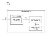
- FIG. 1is a block diagram illustrating one embodiment of an exercise machine 102 that implements the systems and methods described herein.
- the exercise machine 102may include a power supply 104 , a DC motor controller 108 , and a DC motor 110 .
- the power supply 104may receive power from a mains power supply via connection 112 .
- connection 112may include a plug that enables the connection 112 to be connected to the mains power supply (through a wall outlet, for example).
- the mains power supplymay have the limitations of a typical residential circuit.
- the mains power supplymay provide a single 120 volt leg of AC power with a maximum current of 15 amps.
- the power supply 104may be configured to operate within the limitations of the typical residential circuit. It is noted that the parameters of the typical residential circuit may vary with location (the European standard may differ from the North American standard, for example).
- the power supply 104may receive an input AC via connection 112 and may output a high voltage DC via connection 114 .
- the power supply 104may receive 120 volts AC and may output 220 volts DC.
- the power supply 104may include high efficiency circuitry 106 .
- the high efficiency circuitrymay enable the conversion of AC power to DC power with very high efficiency (e.g., 97%).
- the DC motor controller 108may receive high voltage DC via connection 114 and may output pulse-width modulated DC to the DC motor 110 via connection 116 .
- the DC motor controller 108may switch the high voltage DC on and off (using MOSFETs, for example) to generate the pulse-width modulated DC signal.
- the DC motor controller 108may generate the pulse-width modulated DC signal to cause the DC motor 110 to rotate at a specific speed.
- FIG. 2is a block diagram illustrating one example of a power supply 104 - a .
- the power supply 104 - amay be one example of the power supply 104 illustrated in FIG. 1 .
- the power supply 104 - amay include rectifying circuitry 202 and the high efficiency circuitry 106 .
- the rectifying circuitry 202may include a rectifier 204 and a filter 208 .
- the rectifier 204may convert AC to DC.
- rectifier 204may receive the input AC via connection 112 and may output rectified DC to the filter 208 via connection 206 .
- the rectifier 204may include a bridge rectifier.
- the filter 208may filter the received rectified DC via connection 206 and may output filtered DC via connection 210 .
- the filter 208may include one or more capacitors for smoothing and filtering out the high frequency components of the rectified DC.
- the high efficiency circuitry 106may perform DC to DC conversion.
- the high efficiency circuitry 106may receive filtered DC via connection 210 and may output high voltage DC via connection 114 .
- the high efficiency circuitry 106may include power factor correction circuitry 212 .
- the power factor correction circuitry 212may correct any phase differences between the voltage waveform and the current waveform of the input AC signal (received via connection 112 , for example).
- the power factor correction circuitry 212may adjust the current waveform to be in phase with the voltage waveform to obtain a power factor of “1.”
- FIG. 3is a block diagram illustrating one example of power factor correction circuitry 212 - a .
- Power factor correction circuitry 212 - amay be one example of the power factor correction circuitry 212 illustrated in FIG. 2 .
- the power factormay be the ratio of real power flowing to the load over the apparent power in the circuit.
- the apparent powermay be the product of the voltage and the current in the circuit.
- the real powermay equal the apparent power when the voltage waveform is in phase with the current waveform. However, the real power may be less than the apparent power when the current waveform is out of phase with the voltage waveform. For example, real power may be less due to a non-linear load (a capacitive and/or inductive load, for example).
- the power factor correction circuitry 212 - amay perform power factor correction to enhance the efficiency of the circuit.
- the power factor correction circuitry 212 - amay include a waveform monitoring module 302 , a processor 314 , and switching circuitry 308 .
- the waveform monitoring module 302may monitor the voltage waveform and the current waveform of the input AC being received via connection 112 .
- the waveform monitoring module 302may include a voltage waveform detector 304 and a current waveform detector 306 .
- the voltage waveform detector 304may detect the voltage waveform of the input AC.
- the voltage waveform detector 304may detect the zero crossings of the voltage waveform to determine the phase of the voltage waveform.
- the current waveform detector 306may detect the current waveform of the input AC.
- the detector 306may detect the zero crossings of the current waveform to determine the phase of the current waveform.
- the waveform monitoring module 302may determine the difference in phase between the current waveform and the voltage waveform.
- the switching circuitry 308may include inductive circuitry 310 and capacitive circuitry 312 .
- the inductive circuitry 310may include one or more inductive elements (e.g., inductor, transformer, coil) and the capacitive circuitry 312 may include one or more capacitive elements (e.g., capacitor).
- the switching circuitry 308may include one or more switches (e.g., MOSFETs) for switching between the inductive circuitry 310 and the capacitive circuitry 312 .
- the processor 314may manage the power factor correction circuitry 212 - a .
- the processor 314may control the switching circuitry 310 based on the waveform monitoring module 302 .
- the processor 314may switch the switching circuitry 308 to include the inductive circuitry 310 .
- the inductive circuitry 310may counteract capacitance occurring in other parts of the circuit which corrects the phase difference between the current waveform and the voltage waveform (thus providing power factor correction).
- the processor 314may switch the switching circuitry 308 to include the capacitive circuitry 312 .
- the addition of the capacitive circuitry 312may counteract the inductance occurring in other parts of the circuitry which corrects the phase difference between the current waveform and the voltage waveform (thus providing power factor correction).
- the switching circuitry 308may be a boost converter, a buck converter, or a buck-boost converter.
- the switching circuitry 308may boost the filtered DC that is received via connection 210 from a first DC voltage to a second DC voltage that is output via connection 114 .
- the switching circuitry 308(when configured as a boost converter, for example) may output 220 volts DC via connection 114 .
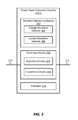
- FIG. 4is a block diagram illustrating one example of a DC motor controller 108 - a .
- the DC motor controller 108 - amay be one example of the DC motor controller 108 illustrated in FIG. 1 .
- the DC motor controller 108 - amay include a communications module 402 , a high efficiency module 404 , and a pulse-width module 406 .
- the communications module 402may receive control commands.
- the communications module 402may receive a control command from the console of a treadmill.
- the control commandmay be a command to spin the motor (or a corresponding treadmill track, for example) at a particular speed (e.g., 16 mph).
- the high efficiency module 404may obtain the control command from the communications module 402 and may direct the pulse-width modulation module 406 to provide the pulse-width modulation necessary to satisfy the control command. For example, the high efficiency module 404 may control the duty cycle that is supplied by the pulse-width modulation module 406 .
- the pulse-width modulation module 406may receive a high voltage DC signal from the power supply 104 via connection 114 .
- the high voltage DC signal(from the power supply 104 ) may include a positive DC signal and a negative DC signal (e.g., +220 volts DC and ⁇ 220 volts DC).
- the pulse-width modulation module 406may switch on and off the high voltage DC signal to generate the pulse-width modulated signal for driving the DC motor 110 .
- the pulse-width modulation module 406may include an isolated gate bi-polar transistor (IGBT) and/or a MOSFET for switching the high voltage DC signal.
- the DC motor controller 108 - amay output the pulse-width modulated DC signal to the DC motor 110 via connection 116 .
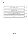
- FIG. 5is a flow diagram illustrating one embodiment of a method 500 for providing high efficiency direct current motor control.
- a direct current signalmay be obtained from a power supply having power factor correction circuitry.
- the direct current signalmay be a high voltage direct current signal.
- the high voltage direct current signalmay include a positive high voltage signal (e.g., +220 volts) and a negative high voltage signal (e.g., ⁇ 220 volts).
- the power supplymay be similar the power supply 104 illustrated in FIG. 1 or 2 .
- a control commandmay be obtained from an exercise machine having a direct current motor.
- the control commandmay be received by the direct current motor controller 108 illustrated in FIG.
- the control commandmay be received from a treadmill control console (e.g., where a user adjusts the speed of the treadmill).
- a pulse-width modulation signalmay be generated from the direct current signal based on the control command.
- the pulse-width modulation signalmay be generated by the direct current motor controller 108 illustrated in FIG. 1 or 4 .
- the pulse-width modulation signalmay be provided to the direct current motor.
- the pulse-width modulation signalmay be used to drive the direct current motor at the speed indicated by the control command.
- FIG. 6is a comparison graph 600 that illustrates the difference in power efficiency between a conventional direct current motor control and the high efficiency direct current motor control of the present systems and methods. It is noted that FIG. 6 illustrates a representation of actual test results.
- graph 600illustrates watts 606 (e.g., power being consumed) with respect to DC volts at the motor 608 (e.g., the DC pulse-width modulated signal that is received via connection 116 ).
- Plots 602 and 604may illustrate the power consumption (in watts) at a particular DC voltage (at the motor).
- Plots 602illustrate the AC input power (e.g., the AC input power being received via connection 112 ).
- plot 602 - a - 1illustrates the AC input power for the high efficiency direct current motor control with no load
- plot 602 - a - 2illustrates the AC input power for the high efficiency direct current motor control with a 180 pound user
- plot 602 - a - 3illustrates the AC input power for the conventional direct current motor control with a 180 pound user
- plots 604illustrate the motor power that is being delivered to the motor (e.g., the pulse-width modulated DC power being received at the DC motor via connection 116 ).
- plot 604 - a - 1illustrates the motor power for the high efficiency direct current motor control with no load
- plot 604 - a - 2illustrates the motor power for the high efficiency direct current motor control with a 180 pound user
- plot 604 - a - 3illustrates the motor power for the conventional direct current motor control with a 180 pound user.
- the difference between the AC input power 602 and the motor power 604may be used to illustrate the efficiency difference between the conventional direct current motor control and the high efficiency direct current motor control.
- the differencefor the conventional direct current motor control with a 180 pound load
- the differenceis around 400 watts. In some cases, this is lost power as a result of poor efficiency in the direct current motor control.
- conventional direct current motor controlis generally between 60-70% efficient.
- the differencefor the high efficiency direct current motor control with a 180 pound user
- the high efficiency direct current motor controlis better than approximately 90% efficient.
- FIG. 7depicts a block diagram of an exercise machine 702 suitable for implementing the present systems and methods.
- the electronic device 702includes a bus 710 which interconnects major subsystems of computer system 702 , such as a central processor 704 , a system memory 706 (typically RAM, but which may also include ROM, flash RAM, or the like), a communications interface 708 , input devices 712 , output device 714 , and storage devices 716 (hard disk, floppy disk, optical disk, etc.).
- Bus 710allows data communication between central processor 704 and system memory 706 , which may include read-only memory (ROM) or flash memory (neither shown), and random access memory (RAM) (not shown), as previously noted.
- the RAMis generally the main memory into which the operating system and application programs are loaded.
- the ROM or flash memorycan contain, among other code, the Basic Input-Output system (BIOS) which controls basic hardware operation such as the interaction with peripheral components or devices.
- BIOSBasic Input-Output system
- the high efficiency module 404 to implement the present systems and methodsmay be stored within the system memory 706 .
- the high efficiency module 404may be an example of the high efficiency module 404 illustrated in FIG. 4 .
- Applications and/or algorithms resident with the electronic device 702are generally stored on and accessed via a non-transitory computer readable medium (stored in the system memory 706 , for example), such as a hard disk drive, an optical drive, a floppy disk unit, or other storage medium. Additionally, applications can be in the form of electronic signals modulated in accordance with the application and data communication technology when accessed via the communications interface 708
- Communications interface 708may provide a direct connection to a remote server or to the Internet via an internet service provider (ISP). Communications interface 708 may provide a direct connection to a remote server via a direct network link to the Internet via a POP (point of presence). Communications interface 708 may provide such connection using wireless techniques, including digital cellular telephone connection, Cellular Digital Packet Data (CDPD) connection, digital satellite data connection, or the like.
- ISPinternet service provider
- POPpoint of presence
- Communications interface 708may provide such connection using wireless techniques, including digital cellular telephone connection, Cellular Digital Packet Data (CDPD) connection, digital satellite data connection, or the like.
- CDPDCellular Digital Packet Data
- the present systems and methodsprovide a high efficiency direct current motor control for an exercise machine.
- the high efficiency direct current motor controlmay enable a user to exercise harder (e.g., run faster) within the limited power that available from a conventional residential circuit.
- the high efficiency direct current motor controlmay be implemented in a treadmill. It is noted that the high efficiency direct current motor control may additionally or alternatively be implemented in an elliptical, bike, or other exercise machine.
- Known DC motor based treadmillsare typically limited to a 12 mph treadmill speed. Thus, users desiring to run faster than 12 mph may be unable to because the treadmill is unable to go faster than 12 mph. In general, this speed limitation is the result of not being able to get more power to the DC motor.
- Known DC motor based treadmillsconvert input AC into 160 volt high voltage DC that is switched into a pulse-width modulation DC voltage for driving the DC motor. However, in known treadmills, the 160 volt high voltage DC may be insufficient for going faster than 12 mph. It is noted that, known DC motor based treadmills are typically 60%-70% efficient.
- the present systems and methodsprovide a high efficiency direct current motor control for a treadmill.
- the high efficiency direct current motor controlmay enable a user to run faster than 20 mph while using the power available in a traditional residential circuit.
- a high efficiency treadmill motor controlmay convert 108-132 volts AC to 220 volts DC with approximately 95% to 97% efficiency (using power factor correction, for example). In some cases, the switching to generate the pulse-width modulated DC signal may cause additional losses, but the high efficiency treadmill motor control may provide pulse-width modulated DC power to the treadmill motor with more than approximately 90% efficiency. Thus, the high efficiency treadmill motor control may be able to provide more power to the motor.
- the high efficiency treadmill motor controlmay allow a user to run faster (e.g., up to 20 mph or more).
- the high efficiency treadmill motor controlmay additionally allow the treadmill to operate more efficiently.
- a usermay run faster while using less power.
- the ability to run faster than 12 mphmay encourage users to run faster. Additionally, the ability to use less energy while running may encourage users to run longer.
Landscapes
- Health & Medical Sciences (AREA)
- Physical Education & Sports Medicine (AREA)
- General Health & Medical Sciences (AREA)
- Vascular Medicine (AREA)
- Cardiology (AREA)
- Engineering & Computer Science (AREA)
- Orthopedic Medicine & Surgery (AREA)
- Power Engineering (AREA)
- Biophysics (AREA)
- Physics & Mathematics (AREA)
- Life Sciences & Earth Sciences (AREA)
- Electromagnetism (AREA)
- Mechanical Engineering (AREA)
- Rectifiers (AREA)
- Control Of Ac Motors In General (AREA)
Abstract
Description
Claims (9)
Priority Applications (3)
| Application Number | Priority Date | Filing Date | Title |
|---|---|---|---|
| US13/860,255US9278248B2 (en) | 2012-04-12 | 2013-04-10 | High efficiency treadmill motor control |
| US15/013,765US9375605B2 (en) | 2012-04-12 | 2016-02-02 | High efficiency treadmill motor control |
| US15/195,692US10207145B2 (en) | 2012-04-12 | 2016-06-28 | High efficiency treadmill motor control |
Applications Claiming Priority (2)
| Application Number | Priority Date | Filing Date | Title |
|---|---|---|---|
| US201261623071P | 2012-04-12 | 2012-04-12 | |
| US13/860,255US9278248B2 (en) | 2012-04-12 | 2013-04-10 | High efficiency treadmill motor control |
Related Child Applications (1)
| Application Number | Title | Priority Date | Filing Date |
|---|---|---|---|
| US15/013,765ContinuationUS9375605B2 (en) | 2012-04-12 | 2016-02-02 | High efficiency treadmill motor control |
Publications (2)
| Publication Number | Publication Date |
|---|---|
| US20130274063A1 US20130274063A1 (en) | 2013-10-17 |
| US9278248B2true US9278248B2 (en) | 2016-03-08 |
Family
ID=49325591
Family Applications (3)
| Application Number | Title | Priority Date | Filing Date |
|---|---|---|---|
| US13/860,255Active2033-10-12US9278248B2 (en) | 2012-04-12 | 2013-04-10 | High efficiency treadmill motor control |
| US15/013,765ActiveUS9375605B2 (en) | 2012-04-12 | 2016-02-02 | High efficiency treadmill motor control |
| US15/195,692Active2033-07-05US10207145B2 (en) | 2012-04-12 | 2016-06-28 | High efficiency treadmill motor control |
Family Applications After (2)
| Application Number | Title | Priority Date | Filing Date |
|---|---|---|---|
| US15/013,765ActiveUS9375605B2 (en) | 2012-04-12 | 2016-02-02 | High efficiency treadmill motor control |
| US15/195,692Active2033-07-05US10207145B2 (en) | 2012-04-12 | 2016-06-28 | High efficiency treadmill motor control |
Country Status (2)
| Country | Link |
|---|---|
| US (3) | US9278248B2 (en) |
| CN (1) | CN103378780B (en) |
Cited By (43)
| Publication number | Priority date | Publication date | Assignee | Title |
|---|---|---|---|---|
| US20140077494A1 (en)* | 2012-09-14 | 2014-03-20 | Robert Sutkowski | Methods and apparatus to power an exercise machine |
| US20160303421A1 (en)* | 2012-04-12 | 2016-10-20 | Icon Health & Fitness, Inc. | High Efficiency Treadmill Motor Control |
| US10449416B2 (en) | 2015-08-26 | 2019-10-22 | Icon Health & Fitness, Inc. | Strength exercise mechanisms |
| US10471299B2 (en) | 2016-07-01 | 2019-11-12 | Icon Health & Fitness, Inc. | Systems and methods for cooling internal exercise equipment components |
| US10493349B2 (en) | 2016-03-18 | 2019-12-03 | Icon Health & Fitness, Inc. | Display on exercise device |
| US10561893B2 (en) | 2016-10-12 | 2020-02-18 | Icon Health & Fitness, Inc. | Linear bearing for console positioning |
| US10561894B2 (en) | 2016-03-18 | 2020-02-18 | Icon Health & Fitness, Inc. | Treadmill with removable supports |
| US10709925B2 (en) | 2013-03-14 | 2020-07-14 | Icon Health & Fitness, Inc. | Strength training apparatus |
| US10758767B2 (en) | 2013-12-26 | 2020-09-01 | Icon Health & Fitness, Inc. | Resistance mechanism in a cable exercise machine |
| US10786706B2 (en) | 2018-07-13 | 2020-09-29 | Icon Health & Fitness, Inc. | Cycling shoe power sensors |
| US10864407B2 (en) | 2016-03-18 | 2020-12-15 | Icon Health & Fitness, Inc. | Coordinated weight selection |
| US10918905B2 (en) | 2016-10-12 | 2021-02-16 | Icon Health & Fitness, Inc. | Systems and methods for reducing runaway resistance on an exercise device |
| US10932517B2 (en) | 2014-03-10 | 2021-03-02 | Icon Health & Fitness, Inc. | Pressure sensor to quantify work |
| US10940360B2 (en) | 2015-08-26 | 2021-03-09 | Icon Health & Fitness, Inc. | Strength exercise mechanisms |
| US10953305B2 (en) | 2015-08-26 | 2021-03-23 | Icon Health & Fitness, Inc. | Strength exercise mechanisms |
| US10994173B2 (en) | 2016-05-13 | 2021-05-04 | Icon Health & Fitness, Inc. | Weight platform treadmill |
| US11000730B2 (en) | 2018-03-16 | 2021-05-11 | Icon Health & Fitness, Inc. | Elliptical exercise machine |
| US11033777B1 (en) | 2019-02-12 | 2021-06-15 | Icon Health & Fitness, Inc. | Stationary exercise machine |
| US11058913B2 (en) | 2017-12-22 | 2021-07-13 | Icon Health & Fitness, Inc. | Inclinable exercise machine |
| US11058914B2 (en) | 2016-07-01 | 2021-07-13 | Icon Health & Fitness, Inc. | Cooling methods for exercise equipment |
| US11187285B2 (en) | 2017-12-09 | 2021-11-30 | Icon Health & Fitness, Inc. | Systems and methods for selectively rotationally fixing a pedaled drivetrain |
| US11244751B2 (en) | 2012-10-19 | 2022-02-08 | Finish Time Holdings, Llc | Method and device for providing a person with training data of an athlete as the athlete is performing a swimming workout |
| US11298577B2 (en) | 2019-02-11 | 2022-04-12 | Ifit Inc. | Cable and power rack exercise machine |
| US11326673B2 (en) | 2018-06-11 | 2022-05-10 | Ifit Inc. | Increased durability linear actuator |
| US11451108B2 (en) | 2017-08-16 | 2022-09-20 | Ifit Inc. | Systems and methods for axial impact resistance in electric motors |
| US11534651B2 (en) | 2019-08-15 | 2022-12-27 | Ifit Inc. | Adjustable dumbbell system |
| US11534654B2 (en) | 2019-01-25 | 2022-12-27 | Ifit Inc. | Systems and methods for an interactive pedaled exercise device |
| US11673036B2 (en) | 2019-11-12 | 2023-06-13 | Ifit Inc. | Exercise storage system |
| US11794070B2 (en) | 2019-05-23 | 2023-10-24 | Ifit Inc. | Systems and methods for cooling an exercise device |
| US11850497B2 (en) | 2019-10-11 | 2023-12-26 | Ifit Inc. | Modular exercise device |
| US11878199B2 (en) | 2021-02-16 | 2024-01-23 | Ifit Inc. | Safety mechanism for an adjustable dumbbell |
| US11931621B2 (en) | 2020-03-18 | 2024-03-19 | Ifit Inc. | Systems and methods for treadmill drift avoidance |
| US11951377B2 (en) | 2020-03-24 | 2024-04-09 | Ifit Inc. | Leaderboard with irregularity flags in an exercise machine system |
| US12029935B2 (en) | 2021-08-19 | 2024-07-09 | Ifit Inc. | Adjustment mechanism for an adjustable kettlebell |
| US12029961B2 (en) | 2020-03-24 | 2024-07-09 | Ifit Inc. | Flagging irregularities in user performance in an exercise machine system |
| US12176009B2 (en) | 2021-12-30 | 2024-12-24 | Ifit Inc. | Systems and methods for synchronizing workout equipment with video files |
| US12219201B2 (en) | 2021-08-05 | 2025-02-04 | Ifit Inc. | Synchronizing video workout programs across multiple devices |
| US12263371B2 (en) | 2021-04-27 | 2025-04-01 | Ifit Inc. | Devices, systems, and methods for rotating a tread belt in two directions |
| US12280294B2 (en) | 2021-10-15 | 2025-04-22 | Ifit Inc. | Magnetic clutch for a pedaled drivetrain |
| US12350547B2 (en) | 2022-02-28 | 2025-07-08 | Ifit Inc. | Devices, systems, and methods for moving a movable step through a transition zone |
| US12350573B2 (en) | 2021-04-27 | 2025-07-08 | Ifit Inc. | Systems and methods for cross-training on exercise devices |
| US12409375B2 (en) | 2022-03-18 | 2025-09-09 | Ifit Inc. | Systems and methods for haptic simulation in incline exercise devices |
| US12433815B2 (en) | 2020-10-02 | 2025-10-07 | Ifit Inc. | Massage roller with pressure sensors |
Families Citing this family (15)
| Publication number | Priority date | Publication date | Assignee | Title |
|---|---|---|---|---|
| WO2015191445A1 (en) | 2014-06-09 | 2015-12-17 | Icon Health & Fitness, Inc. | Cable system incorporated into a treadmill |
| US10258828B2 (en) | 2015-01-16 | 2019-04-16 | Icon Health & Fitness, Inc. | Controls for an exercise device |
| US10625137B2 (en) | 2016-03-18 | 2020-04-21 | Icon Health & Fitness, Inc. | Coordinated displays in an exercise device |
| US10272317B2 (en) | 2016-03-18 | 2019-04-30 | Icon Health & Fitness, Inc. | Lighted pace feature in a treadmill |
| CN105656303A (en)* | 2016-04-07 | 2016-06-08 | 湖州积微电子科技有限公司 | Driving system of treadmill |
| US10441844B2 (en) | 2016-07-01 | 2019-10-15 | Icon Health & Fitness, Inc. | Cooling systems and methods for exercise equipment |
| US10500473B2 (en) | 2016-10-10 | 2019-12-10 | Icon Health & Fitness, Inc. | Console positioning |
| US10207148B2 (en) | 2016-10-12 | 2019-02-19 | Icon Health & Fitness, Inc. | Systems and methods for reducing runaway resistance on an exercise device |
| US10376736B2 (en) | 2016-10-12 | 2019-08-13 | Icon Health & Fitness, Inc. | Cooling an exercise device during a dive motor runway condition |
| US11185740B2 (en)* | 2016-10-19 | 2021-11-30 | Board Of Regents Of The University Of Nebraska | User-paced exercise equipment |
| US10661114B2 (en) | 2016-11-01 | 2020-05-26 | Icon Health & Fitness, Inc. | Body weight lift mechanism on treadmill |
| TWI646997B (en) | 2016-11-01 | 2019-01-11 | 美商愛康運動與健康公司 | Distance sensor for console positioning |
| TWI680782B (en) | 2016-12-05 | 2020-01-01 | 美商愛康運動與健康公司 | Offsetting treadmill deck weight during operation |
| US10729965B2 (en) | 2017-12-22 | 2020-08-04 | Icon Health & Fitness, Inc. | Audible belt guide in a treadmill |
| US11596837B1 (en)* | 2022-01-11 | 2023-03-07 | Tonal Systems, Inc. | Exercise machine suggested weights |
Citations (6)
| Publication number | Priority date | Publication date | Assignee | Title |
|---|---|---|---|---|
| US5545112A (en)* | 1991-11-08 | 1996-08-13 | Quinton Instrument Company | D.C. treadmill speed change motor controller system |
| US5586736A (en)* | 1995-06-16 | 1996-12-24 | Harmon Industries, Inc. | Cab signal sensor with noise suppression |
| US6443875B1 (en) | 1999-09-07 | 2002-09-03 | Brunswich Corporation | Treadmill motor control |
| CN1768880A (en) | 2004-11-02 | 2006-05-10 | 乔山健康科技股份有限公司 | Treadmill motor drive control circuit |
| CN201436042U (en) | 2009-06-13 | 2010-04-07 | 青岛英派斯(集团)有限公司 | Booster circuit for electric mark time device |
| US20150065301A1 (en)* | 2010-11-02 | 2015-03-05 | Strength Companion, LLC | Method of Harvesting Energy from Exercise Equipment |
Family Cites Families (13)
| Publication number | Priority date | Publication date | Assignee | Title |
|---|---|---|---|---|
| CA2061470C (en)* | 1991-03-18 | 2000-04-11 | Eugene B. Szymczak | Exercise treadmill and method |
| SG44798A1 (en)* | 1994-02-10 | 1997-12-19 | Philips Electronics Nv | High frequency ac/ac converter with power factor correction |
| US5643142A (en)* | 1995-05-01 | 1997-07-01 | Jas Manufacturing Co., Inc. | AC motor driven treadmill |
| CN2330944Y (en)* | 1998-02-13 | 1999-07-28 | 西安飞机工业科技开发中心航城机械厂 | Semi-conductor refrigerator air conditioning machine |
| CN2388632Y (en)* | 1999-06-08 | 2000-07-19 | 镒福电子股份有限公司 | AC power regulator |
| US6443876B1 (en) | 2001-04-03 | 2002-09-03 | Yu-Tong Huang | Belt position device for waist exerciser |
| US6837830B2 (en)* | 2002-11-01 | 2005-01-04 | Mark W. Eldridge | Apparatus using multi-directional resistance in exercise equipment |
| US7618346B2 (en)* | 2003-02-28 | 2009-11-17 | Nautilus, Inc. | System and method for controlling an exercise apparatus |
| CN101621247B (en)* | 2009-07-23 | 2012-05-23 | 艾默生网络能源有限公司 | Power factor correction circuit |
| US8485944B2 (en)* | 2010-04-21 | 2013-07-16 | Jeffrey M Drazan | Contribution of energy to an intelligent electrical network through an exercise apparatus |
| US9278248B2 (en)* | 2012-04-12 | 2016-03-08 | Icon Health & Fitness, Inc. | High efficiency treadmill motor control |
| US9763604B1 (en)* | 2016-04-09 | 2017-09-19 | Bertec Corporation | Gait perturbation system and a method for testing and/or training a subject using the same |
| US9622686B1 (en)* | 2016-04-09 | 2017-04-18 | Bertec Corporation | Gait perturbation system and a method for testing and/or training a subject using the same |
- 2013
- 2013-04-10USUS13/860,255patent/US9278248B2/enactiveActive
- 2013-04-11CNCN201310124576.4Apatent/CN103378780B/enactiveActive
- 2016
- 2016-02-02USUS15/013,765patent/US9375605B2/enactiveActive
- 2016-06-28USUS15/195,692patent/US10207145B2/enactiveActive
Patent Citations (6)
| Publication number | Priority date | Publication date | Assignee | Title |
|---|---|---|---|---|
| US5545112A (en)* | 1991-11-08 | 1996-08-13 | Quinton Instrument Company | D.C. treadmill speed change motor controller system |
| US5586736A (en)* | 1995-06-16 | 1996-12-24 | Harmon Industries, Inc. | Cab signal sensor with noise suppression |
| US6443875B1 (en) | 1999-09-07 | 2002-09-03 | Brunswich Corporation | Treadmill motor control |
| CN1768880A (en) | 2004-11-02 | 2006-05-10 | 乔山健康科技股份有限公司 | Treadmill motor drive control circuit |
| CN201436042U (en) | 2009-06-13 | 2010-04-07 | 青岛英派斯(集团)有限公司 | Booster circuit for electric mark time device |
| US20150065301A1 (en)* | 2010-11-02 | 2015-03-05 | Strength Companion, LLC | Method of Harvesting Energy from Exercise Equipment |
Non-Patent Citations (3)
| Title |
|---|
| English translation of Chinese First Office Action and Search Report issued for Chinese Patent Application No. 2013101245764 on Jul. 22, 2015. |
| Machine English Translation of Abstract of Chinese Patent No. CN1768880A. May 10, 2000. |
| Machine English Translation of Abstract of Chinese Patent No. CN201436042U. Apr. 7, 2010. |
Cited By (77)
| Publication number | Priority date | Publication date | Assignee | Title |
|---|---|---|---|---|
| US10207145B2 (en)* | 2012-04-12 | 2019-02-19 | Icon Health & Fitness, Inc. | High efficiency treadmill motor control |
| US20160303421A1 (en)* | 2012-04-12 | 2016-10-20 | Icon Health & Fitness, Inc. | High Efficiency Treadmill Motor Control |
| US20140077494A1 (en)* | 2012-09-14 | 2014-03-20 | Robert Sutkowski | Methods and apparatus to power an exercise machine |
| US20170128763A1 (en)* | 2012-09-14 | 2017-05-11 | Brunswick Corporation | Methods and apparatus to power an exercise machine |
| US9737746B2 (en)* | 2012-09-14 | 2017-08-22 | Brunswick Corporation | Methods and apparatus to power an exercise machine |
| US20170340913A1 (en)* | 2012-09-14 | 2017-11-30 | Brunswick Corporation | Methods and apparatus to power an exercise machine |
| US9943718B2 (en)* | 2012-09-14 | 2018-04-17 | Brunswick Corporation | Methods and apparatus to power an exercise machine |
| US9579534B2 (en)* | 2012-09-14 | 2017-02-28 | Brunswick Corporation | Methods and apparatus to power an exercise machine |
| US11810656B2 (en) | 2012-10-19 | 2023-11-07 | Finish Time Holdings, Llc | System for providing a coach with live training data of an athlete as the athlete is training |
| US11244751B2 (en) | 2012-10-19 | 2022-02-08 | Finish Time Holdings, Llc | Method and device for providing a person with training data of an athlete as the athlete is performing a swimming workout |
| US11923066B2 (en) | 2012-10-19 | 2024-03-05 | Finish Time Holdings, Llc | System and method for providing a trainer with live training data of an individual as the individual is performing a training workout |
| US11322240B2 (en) | 2012-10-19 | 2022-05-03 | Finish Time Holdings, Llc | Method and device for providing a person with training data of an athlete as the athlete is performing a running workout |
| US12340891B2 (en) | 2012-10-19 | 2025-06-24 | Finish Time Network LLC | System and method for providing a trainer with live training data of an individual as the individual is performing a training workout |
| US11878206B2 (en) | 2013-03-14 | 2024-01-23 | Ifit Inc. | Strength training apparatus |
| US10709925B2 (en) | 2013-03-14 | 2020-07-14 | Icon Health & Fitness, Inc. | Strength training apparatus |
| US10953268B1 (en) | 2013-03-14 | 2021-03-23 | Icon Health & Fitness, Inc. | Strength training apparatus |
| US11338169B2 (en) | 2013-03-14 | 2022-05-24 | IFIT, Inc. | Strength training apparatus |
| US10967214B1 (en) | 2013-12-26 | 2021-04-06 | Icon Health & Fitness, Inc. | Cable exercise machine |
| US10758767B2 (en) | 2013-12-26 | 2020-09-01 | Icon Health & Fitness, Inc. | Resistance mechanism in a cable exercise machine |
| US10932517B2 (en) | 2014-03-10 | 2021-03-02 | Icon Health & Fitness, Inc. | Pressure sensor to quantify work |
| US11700905B2 (en) | 2014-03-10 | 2023-07-18 | Ifit Inc. | Pressure sensor to quantify work |
| US10940360B2 (en) | 2015-08-26 | 2021-03-09 | Icon Health & Fitness, Inc. | Strength exercise mechanisms |
| US10953305B2 (en) | 2015-08-26 | 2021-03-23 | Icon Health & Fitness, Inc. | Strength exercise mechanisms |
| US10449416B2 (en) | 2015-08-26 | 2019-10-22 | Icon Health & Fitness, Inc. | Strength exercise mechanisms |
| US12029944B2 (en) | 2016-03-18 | 2024-07-09 | Ifit Inc. | Stationary exercise machine configured to execute a programmed workout with aerobic portions and lifting portions |
| US10864407B2 (en) | 2016-03-18 | 2020-12-15 | Icon Health & Fitness, Inc. | Coordinated weight selection |
| US11794075B2 (en) | 2016-03-18 | 2023-10-24 | Ifit Inc. | Stationary exercise machine configured to execute a programmed workout with aerobic portions and lifting portions |
| US10561894B2 (en) | 2016-03-18 | 2020-02-18 | Icon Health & Fitness, Inc. | Treadmill with removable supports |
| US12023549B2 (en) | 2016-03-18 | 2024-07-02 | Ifit Inc. | Stationary exercise machine configured to execute a programmed workout with aerobic portions and lifting portions |
| US10493349B2 (en) | 2016-03-18 | 2019-12-03 | Icon Health & Fitness, Inc. | Display on exercise device |
| US12029943B2 (en) | 2016-03-18 | 2024-07-09 | Ifit Inc. | Stationary exercise machine configured to execute a programmed workout with aerobic portions and lifting portions |
| US11013960B2 (en) | 2016-03-18 | 2021-05-25 | Icon Health & Fitness, Inc. | Exercise system including a stationary bicycle and a free weight cradle |
| US11565148B2 (en) | 2016-03-18 | 2023-01-31 | Ifit Inc. | Treadmill with a scale mechanism in a motor cover |
| US11779812B2 (en) | 2016-05-13 | 2023-10-10 | Ifit Inc. | Treadmill configured to automatically determine user exercise movement |
| US10994173B2 (en) | 2016-05-13 | 2021-05-04 | Icon Health & Fitness, Inc. | Weight platform treadmill |
| US11058914B2 (en) | 2016-07-01 | 2021-07-13 | Icon Health & Fitness, Inc. | Cooling methods for exercise equipment |
| US10471299B2 (en) | 2016-07-01 | 2019-11-12 | Icon Health & Fitness, Inc. | Systems and methods for cooling internal exercise equipment components |
| US10561893B2 (en) | 2016-10-12 | 2020-02-18 | Icon Health & Fitness, Inc. | Linear bearing for console positioning |
| US10918905B2 (en) | 2016-10-12 | 2021-02-16 | Icon Health & Fitness, Inc. | Systems and methods for reducing runaway resistance on an exercise device |
| US11451108B2 (en) | 2017-08-16 | 2022-09-20 | Ifit Inc. | Systems and methods for axial impact resistance in electric motors |
| US11680611B2 (en) | 2017-12-09 | 2023-06-20 | Ifit Inc. | Systems and methods for selectively rotationally fixing a pedaled drivetrain |
| US11187285B2 (en) | 2017-12-09 | 2021-11-30 | Icon Health & Fitness, Inc. | Systems and methods for selectively rotationally fixing a pedaled drivetrain |
| US11708874B2 (en) | 2017-12-09 | 2023-07-25 | Ifit Inc. | Systems and methods for selectively rotationally fixing a pedaled drivetrain |
| US12270441B2 (en) | 2017-12-09 | 2025-04-08 | Ifit Inc. | Systems and methods for selectively rotationally fixing a pedaled drivetrain |
| US11058913B2 (en) | 2017-12-22 | 2021-07-13 | Icon Health & Fitness, Inc. | Inclinable exercise machine |
| US11596830B2 (en) | 2018-03-16 | 2023-03-07 | Ifit Inc. | Elliptical exercise machine |
| US11000730B2 (en) | 2018-03-16 | 2021-05-11 | Icon Health & Fitness, Inc. | Elliptical exercise machine |
| US11326673B2 (en) | 2018-06-11 | 2022-05-10 | Ifit Inc. | Increased durability linear actuator |
| US10786706B2 (en) | 2018-07-13 | 2020-09-29 | Icon Health & Fitness, Inc. | Cycling shoe power sensors |
| US12005315B2 (en) | 2018-07-13 | 2024-06-11 | Ifit Inc. | Cycling shoe power sensors |
| US11534654B2 (en) | 2019-01-25 | 2022-12-27 | Ifit Inc. | Systems and methods for an interactive pedaled exercise device |
| US11452903B2 (en) | 2019-02-11 | 2022-09-27 | Ifit Inc. | Exercise machine |
| US11298577B2 (en) | 2019-02-11 | 2022-04-12 | Ifit Inc. | Cable and power rack exercise machine |
| US11642564B2 (en) | 2019-02-11 | 2023-05-09 | Ifit Inc. | Exercise machine |
| US11033777B1 (en) | 2019-02-12 | 2021-06-15 | Icon Health & Fitness, Inc. | Stationary exercise machine |
| US11951358B2 (en) | 2019-02-12 | 2024-04-09 | Ifit Inc. | Encoding exercise machine control commands in subtitle streams |
| US11426633B2 (en) | 2019-02-12 | 2022-08-30 | Ifit Inc. | Controlling an exercise machine using a video workout program |
| US11058918B1 (en) | 2019-02-12 | 2021-07-13 | Icon Health & Fitness, Inc. | Producing a workout video to control a stationary exercise machine |
| US11794070B2 (en) | 2019-05-23 | 2023-10-24 | Ifit Inc. | Systems and methods for cooling an exercise device |
| US11534651B2 (en) | 2019-08-15 | 2022-12-27 | Ifit Inc. | Adjustable dumbbell system |
| US11850497B2 (en) | 2019-10-11 | 2023-12-26 | Ifit Inc. | Modular exercise device |
| US12296247B2 (en) | 2019-10-11 | 2025-05-13 | Ifit Inc. | Modular exercise device |
| US11673036B2 (en) | 2019-11-12 | 2023-06-13 | Ifit Inc. | Exercise storage system |
| US11931621B2 (en) | 2020-03-18 | 2024-03-19 | Ifit Inc. | Systems and methods for treadmill drift avoidance |
| US11951377B2 (en) | 2020-03-24 | 2024-04-09 | Ifit Inc. | Leaderboard with irregularity flags in an exercise machine system |
| US12029961B2 (en) | 2020-03-24 | 2024-07-09 | Ifit Inc. | Flagging irregularities in user performance in an exercise machine system |
| US12433815B2 (en) | 2020-10-02 | 2025-10-07 | Ifit Inc. | Massage roller with pressure sensors |
| US12239872B2 (en) | 2021-02-16 | 2025-03-04 | Ifit Inc. | Safety mechanism for an adjustable dumbbell |
| US11878199B2 (en) | 2021-02-16 | 2024-01-23 | Ifit Inc. | Safety mechanism for an adjustable dumbbell |
| US12263371B2 (en) | 2021-04-27 | 2025-04-01 | Ifit Inc. | Devices, systems, and methods for rotating a tread belt in two directions |
| US12350573B2 (en) | 2021-04-27 | 2025-07-08 | Ifit Inc. | Systems and methods for cross-training on exercise devices |
| US12219201B2 (en) | 2021-08-05 | 2025-02-04 | Ifit Inc. | Synchronizing video workout programs across multiple devices |
| US12029935B2 (en) | 2021-08-19 | 2024-07-09 | Ifit Inc. | Adjustment mechanism for an adjustable kettlebell |
| US12280294B2 (en) | 2021-10-15 | 2025-04-22 | Ifit Inc. | Magnetic clutch for a pedaled drivetrain |
| US12176009B2 (en) | 2021-12-30 | 2024-12-24 | Ifit Inc. | Systems and methods for synchronizing workout equipment with video files |
| US12350547B2 (en) | 2022-02-28 | 2025-07-08 | Ifit Inc. | Devices, systems, and methods for moving a movable step through a transition zone |
| US12409375B2 (en) | 2022-03-18 | 2025-09-09 | Ifit Inc. | Systems and methods for haptic simulation in incline exercise devices |
Also Published As
| Publication number | Publication date |
|---|---|
| US20160151661A1 (en) | 2016-06-02 |
| US9375605B2 (en) | 2016-06-28 |
| US10207145B2 (en) | 2019-02-19 |
| US20160303421A1 (en) | 2016-10-20 |
| US20130274063A1 (en) | 2013-10-17 |
| CN103378780A (en) | 2013-10-30 |
| CN103378780B (en) | 2016-12-28 |
Similar Documents
| Publication | Publication Date | Title |
|---|---|---|
| US9375605B2 (en) | High efficiency treadmill motor control | |
| CN103457492B (en) | Offline voltage regulator and voltage conversion method thereof | |
| US9148072B2 (en) | Inverter apparatus | |
| US8503204B2 (en) | Power converter circuit | |
| Kim et al. | New modulated carrier controlled PFC boost converter | |
| US20160294296A1 (en) | Universal System Structure for Low Power Adapters | |
| CN102820799B (en) | Switching power supply circuit, semiconductor device, and LED lighting device | |
| WO2016051797A1 (en) | Electric power conversion device | |
| WO2018169520A1 (en) | Single-stage transmitter for wireless power transfer | |
| JP2013538544A (en) | AC / DC power conversion method and apparatus | |
| CN103683919B (en) | High-power-factor low-harmonic-distortconstant constant current circuit and device | |
| CN103597721B (en) | Nonisulated step-down switching regulator and control circuit, electronic equipment, AC adapter | |
| US9438131B2 (en) | AC-DC converter | |
| TW201106590A (en) | Parallel connected PFC converters | |
| US9433060B2 (en) | Power factor correction circuit, operating device for a light-emitting means and method for controlling a power factor correction circuit | |
| KR101911262B1 (en) | Power transforming apparatus having noise reduction function and air conditioner including the same | |
| CN114123740A (en) | Control method, control device and electronic equipment of switching power supply | |
| CN204168555U (en) | Power circuit and lighting device | |
| KR102174638B1 (en) | Power transforming apparatus having noise reduction function, compressor including the same and the method for the same | |
| CN109804540A (en) | For operating method, control device and the DC-DC converter of DC-DC converter | |
| JP6882798B2 (en) | How to supply power to power supply devices and loads | |
| JP2021507671A (en) | Wide range of power supplies for use in meters and other devices | |
| JP2014103742A (en) | Synchronous rectifier converter | |
| KR101832783B1 (en) | Power supply apparatus having power saving function and dehumidifier including the same | |
| JP2006042579A (en) | Switching control method, rectifier, and drive system |
Legal Events
| Date | Code | Title | Description |
|---|---|---|---|
| AS | Assignment | Owner name:ICON HELATH & FITNESS, INC., UTAH Free format text:ASSIGNMENT OF ASSIGNORS INTEREST;ASSIGNORS:TYGER, MICHAEL J.;WILLIAMS, DERREK;SIGNING DATES FROM 20130502 TO 20130506;REEL/FRAME:033055/0928 | |
| AS | Assignment | Owner name:BANK OF AMERICA, N.A., AS ADMINISTRATIVE AGENT, MA Free format text:SECURITY AGREEMENT;ASSIGNORS:ICON HEALTH & FITNESS, INC.;ICON IP, INC.;REEL/FRAME:036104/0833 Effective date:20150710 | |
| STCF | Information on status: patent grant | Free format text:PATENTED CASE | |
| AS | Assignment | Owner name:FREE MOTION FITNESS, INC., UTAH Free format text:RELEASE OF SECURITY INTEREST IN PATENTS;ASSIGNOR:BANK OF AMERICA, N.A., ACTING IN ITS CAPACITY AS AGENT FOR THE LENDERS;REEL/FRAME:039584/0575 Effective date:20160803 Owner name:ICON INTERNATIONAL HOLDINGS, INC., UTAH Free format text:RELEASE OF SECURITY INTEREST IN PATENTS;ASSIGNOR:BANK OF AMERICA, N.A., ACTING IN ITS CAPACITY AS AGENT FOR THE LENDERS;REEL/FRAME:039584/0575 Effective date:20160803 Owner name:ICON - ALTRA LLC, UTAH Free format text:RELEASE OF SECURITY INTEREST IN PATENTS;ASSIGNOR:BANK OF AMERICA, N.A., ACTING IN ITS CAPACITY AS AGENT FOR THE LENDERS;REEL/FRAME:039584/0575 Effective date:20160803 Owner name:HF HOLDINGS, INC., UTAH Free format text:RELEASE OF SECURITY INTEREST IN PATENTS;ASSIGNOR:BANK OF AMERICA, N.A., ACTING IN ITS CAPACITY AS AGENT FOR THE LENDERS;REEL/FRAME:039584/0575 Effective date:20160803 Owner name:ICON IP, INC., UTAH Free format text:RELEASE OF SECURITY INTEREST IN PATENTS;ASSIGNOR:BANK OF AMERICA, N.A., ACTING IN ITS CAPACITY AS AGENT FOR THE LENDERS;REEL/FRAME:039584/0575 Effective date:20160803 Owner name:ICON HEALTH & FITNESS, INC, UTAH Free format text:RELEASE OF SECURITY INTEREST IN PATENTS;ASSIGNOR:BANK OF AMERICA, N.A., ACTING IN ITS CAPACITY AS AGENT FOR THE LENDERS;REEL/FRAME:039584/0575 Effective date:20160803 Owner name:UNIVERSAL TECHNICAL SERVICES, UTAH Free format text:RELEASE OF SECURITY INTEREST IN PATENTS;ASSIGNOR:BANK OF AMERICA, N.A., ACTING IN ITS CAPACITY AS AGENT FOR THE LENDERS;REEL/FRAME:039584/0575 Effective date:20160803 Owner name:ICON DU CANADA INC., CANADA Free format text:RELEASE OF SECURITY INTEREST IN PATENTS;ASSIGNOR:BANK OF AMERICA, N.A., ACTING IN ITS CAPACITY AS AGENT FOR THE LENDERS;REEL/FRAME:039584/0575 Effective date:20160803 | |
| AS | Assignment | Owner name:JPMORGAN CHASE BANK, N.A., AS ADMINISTRATIVE AGENT Free format text:PATENT SECURITY AGREEMENT;ASSIGNORS:ICON HEALTH FITNESS, INC.;HF HOLDINGS, INC.;UNIVERSAL TECHNICAL SERVICES;AND OTHERS;REEL/FRAME:039669/0311 Effective date:20160803 Owner name:JPMORGAN CHASE BANK, N.A., AS ADMINISTRATIVE AGENT Free format text:PATENT SECURITY AGREEMENT;ASSIGNORS:ICON HEALTH & FITNESS, INC.;HF HOLDINGS, INC.;UNIVERSAL TECHNICAL SERVICES;AND OTHERS;REEL/FRAME:039669/0311 Effective date:20160803 | |
| MAFP | Maintenance fee payment | Free format text:PAYMENT OF MAINTENANCE FEE, 4TH YEAR, LARGE ENTITY (ORIGINAL EVENT CODE: M1551); ENTITY STATUS OF PATENT OWNER: LARGE ENTITY Year of fee payment:4 | |
| AS | Assignment | Owner name:ICON IP, INC., UTAH Free format text:TERMINATION AND RELEASE OF SECURITY INTEREST IN PATENT RIGHTS;ASSIGNOR:JPMORGAN CHASE BANK, N.A., AS ADMINISTRATIVE AGENT;REEL/FRAME:052671/0737 Effective date:20200427 Owner name:ICON HEALTH & FITNESS, INC., UTAH Free format text:TERMINATION AND RELEASE OF SECURITY INTEREST IN PATENT RIGHTS;ASSIGNOR:JPMORGAN CHASE BANK, N.A., AS ADMINISTRATIVE AGENT;REEL/FRAME:052671/0737 Effective date:20200427 Owner name:JPMORGAN CHASE BANK, N.A., AS ADMINISTRATIVE AGENT, ILLINOIS Free format text:PATENT SECURITY AGREEMENT;ASSIGNOR:ICON HEALTH & FITNESS, INC.;REEL/FRAME:053548/0453 Effective date:20200427 | |
| AS | Assignment | Owner name:BANK OF AMERICA, N.A., AS ADMINISTRATIVE AGENT, CALIFORNIA Free format text:SECURITY INTEREST;ASSIGNOR:ICON HEALTH & FITNESS, INC.;REEL/FRAME:056238/0818 Effective date:20210512 | |
| AS | Assignment | Owner name:ICON HEALTH & FITNESS, INC., UTAH Free format text:TERMINATION AND RELEASE OF SECURITY INTEREST IN PATENTS;ASSIGNOR:JPMORGAN CHASE BANK, N.A., AS ADMINISTRATIVE AGENT;REEL/FRAME:056654/0951 Effective date:20210512 | |
| AS | Assignment | Owner name:IFIT INC, UTAH Free format text:CHANGE OF NAME;ASSIGNOR:ICON HEALTH & FITNESS, INC.;REEL/FRAME:058742/0476 Effective date:20210809 | |
| AS | Assignment | Owner name:IFIT INC., UTAH Free format text:TO CORRECT AN ERROR IN A COVER SHEET PREVIOUSLY RECORDED AT REEL/FRAME 058742/0476 - CORRECT ASSIGNEE NAME IFIT INC TO IFIT INC;ASSIGNOR:ICON HEALTH & FITNESS, INC.;REEL/FRAME:058957/0531 Effective date:20210809 | |
| AS | Assignment | Owner name:PLC AGENT LLC, MASSACHUSETTS Free format text:SECURITY INTEREST;ASSIGNOR:IFIT INC.;REEL/FRAME:059249/0466 Effective date:20220224 | |
| AS | Assignment | Owner name:ICON PREFERRED HOLDINGS, L.P., UTAH Free format text:INTELLECTUAL PROPERTY SECURITY AGREEMENT;ASSIGNOR:IFIT INC.;REEL/FRAME:059633/0313 Effective date:20220224 | |
| AS | Assignment | Owner name:ICON PREFERRED HOLDINGS, L.P., NEW YORK Free format text:CORRECTIVE ASSIGNMENT TO CORRECT THE THE ASSIGNEE'S ADDRESS PREVIOUSLY RECORDED AT REEL: 059633 FRAME: 0313. ASSIGNOR(S) HEREBY CONFIRMS THE ASSIGNMENT;ASSIGNOR:IFIT INC.;REEL/FRAME:060512/0315 Effective date:20220224 | |
| AS | Assignment | Owner name:LC9 CONNECTED HOLDINGS, LP, CONNECTICUT Free format text:SECURITY INTEREST;ASSIGNORS:IFIT INC.;ICON IP, INC.;REEL/FRAME:059857/0830 Effective date:20220224 | |
| MAFP | Maintenance fee payment | Free format text:PAYMENT OF MAINTENANCE FEE, 8TH YEAR, LARGE ENTITY (ORIGINAL EVENT CODE: M1552); ENTITY STATUS OF PATENT OWNER: LARGE ENTITY Year of fee payment:8 | |
| AS | Assignment | Owner name:LC9 CONNECTED HOLDINGS, LP, CONNECTICUT Free format text:SECURITY INTEREST;ASSIGNORS:IFIT INC.;ICON IP, INC.;REEL/FRAME:066094/0529 Effective date:20231214 | |
| AS | Assignment | Owner name:CERBERUS BUSINESS FINANCE AGENCY, LLC, NEW YORK Free format text:SECURITY INTEREST;ASSIGNOR:IFIT, INC.;REEL/FRAME:071278/0707 Effective date:20250512 | |
| AS | Assignment | Owner name:ICON IP INC., UTAH Free format text:RELEASE BY SECURED PARTY;ASSIGNOR:ICON PREFERRED HOLDINGS, L.P.;REEL/FRAME:071336/0725 Effective date:20250512 Owner name:IFIT INC., UTAH Free format text:RELEASE BY SECURED PARTY;ASSIGNOR:ICON PREFERRED HOLDINGS, L.P.;REEL/FRAME:071336/0725 Effective date:20250512 | |
| AS | Assignment | Owner name:ICON IP, INC., UTAH Free format text:RELEASE BY SECURED PARTY;ASSIGNOR:BANK OF AMERICA, N.A.;REEL/FRAME:071351/0624 Effective date:20250512 Owner name:IFIT, INC. (F/K/A ICON HEALTH & FITNESS, INC.), UTAH Free format text:RELEASE BY SECURED PARTY;ASSIGNOR:BANK OF AMERICA, N.A.;REEL/FRAME:071351/0624 Effective date:20250512 Owner name:ICON IP, INC., UTAH Free format text:RELEASE BY SECURED PARTY;ASSIGNOR:PLC AGENT LLC;REEL/FRAME:071358/0584 Effective date:20250512 Owner name:IFIT INC., UTAH Free format text:RELEASE BY SECURED PARTY;ASSIGNOR:PLC AGENT LLC;REEL/FRAME:071358/0584 Effective date:20250512 | |
| AS | Assignment | Owner name:ICON IP INC., UTAH Free format text:RELEASE BY SECURED PARTY;ASSIGNOR:LC9 CONNECTED HOLDINGS, LP;REEL/FRAME:071407/0001 Effective date:20250512 Owner name:IFIT INC., UTAH Free format text:RELEASE BY SECURED PARTY;ASSIGNOR:LC9 CONNECTED HOLDINGS, LP;REEL/FRAME:071407/0001 Effective date:20250512 | |
| AS | Assignment | Owner name:ICON IP INC., UTAH Free format text:RELEASE OF INTELLECTUAL PROPERTY SECURITY INTEREST (4TH LIEN);ASSIGNOR:LC9 CONNECTED HOLDINGS, LP;REEL/FRAME:071429/0479 Effective date:20250512 Owner name:IFIT INC., UTAH Free format text:RELEASE OF INTELLECTUAL PROPERTY SECURITY INTEREST (4TH LIEN);ASSIGNOR:LC9 CONNECTED HOLDINGS, LP;REEL/FRAME:071429/0479 Effective date:20250512 |