US9277940B2 - System and method for insertion of flexible spinal stabilization element - Google Patents
System and method for insertion of flexible spinal stabilization elementDownload PDFInfo
- Publication number
- US9277940B2 US9277940B2US12/025,984US2598408AUS9277940B2US 9277940 B2US9277940 B2US 9277940B2US 2598408 AUS2598408 AUS 2598408AUS 9277940 B2US9277940 B2US 9277940B2
- Authority
- US
- United States
- Prior art keywords
- connecting element
- delivery device
- vertebral
- vertebral anchor
- positioning tool
- Prior art date
- Legal status (The legal status is an assumption and is not a legal conclusion. Google has not performed a legal analysis and makes no representation as to the accuracy of the status listed.)
- Active, expires
Links
- 238000000034methodMethods0.000titleclaimsabstractdescription70
- 230000006641stabilisationEffects0.000titleclaimsabstractdescription43
- 238000011105stabilizationMethods0.000titleclaimsabstractdescription43
- 238000003780insertionMethods0.000titleclaimsdescription13
- 230000037431insertionEffects0.000titleclaimsdescription13
- 230000008878couplingEffects0.000claimsabstractdescription5
- 238000010168coupling processMethods0.000claimsabstractdescription5
- 238000005859coupling reactionMethods0.000claimsabstractdescription5
- 125000006850spacer groupChemical group0.000claimsdescription47
- 230000000717retained effectEffects0.000claimsdescription4
- 238000004513sizingMethods0.000claims1
- 239000000463materialSubstances0.000description17
- 210000001519tissueAnatomy0.000description10
- 239000007943implantSubstances0.000description7
- 230000000087stabilizing effectEffects0.000description7
- 238000001356surgical procedureMethods0.000description4
- 230000004927fusionEffects0.000description3
- 238000010276constructionMethods0.000description2
- 230000000694effectsEffects0.000description2
- 238000009434installationMethods0.000description2
- 230000013011matingEffects0.000description2
- 239000002184metalSubstances0.000description2
- 229910052751metalInorganic materials0.000description2
- 238000002355open surgical procedureMethods0.000description2
- 229920001692polycarbonate urethanePolymers0.000description2
- -1polyethylene terephthalatePolymers0.000description2
- 229920000139polyethylene terephthalatePolymers0.000description2
- 239000005020polyethylene terephthalateSubstances0.000description2
- 239000012781shape memory materialSubstances0.000description2
- 239000004696Poly ether ether ketoneSubstances0.000description1
- 239000004698PolyethyleneSubstances0.000description1
- 208000020307Spinal diseaseDiseases0.000description1
- RTAQQCXQSZGOHL-UHFFFAOYSA-NTitaniumChemical compound[Ti]RTAQQCXQSZGOHL-UHFFFAOYSA-N0.000description1
- 230000002159abnormal effectEffects0.000description1
- 230000002411adverseEffects0.000description1
- 238000013459approachMethods0.000description1
- JUPQTSLXMOCDHR-UHFFFAOYSA-Nbenzene-1,4-diol;bis(4-fluorophenyl)methanoneChemical compoundOC1=CC=C(O)C=C1.C1=CC(F)=CC=C1C(=O)C1=CC=C(F)C=C1JUPQTSLXMOCDHR-UHFFFAOYSA-N0.000description1
- 230000036760body temperatureEffects0.000description1
- 210000000988bone and boneAnatomy0.000description1
- 239000002639bone cementSubstances0.000description1
- 230000008859changeEffects0.000description1
- 230000006835compressionEffects0.000description1
- 238000007906compressionMethods0.000description1
- 238000007796conventional methodMethods0.000description1
- 230000001419dependent effectEffects0.000description1
- 239000013013elastic materialSubstances0.000description1
- 239000000945fillerSubstances0.000description1
- 239000003550markerSubstances0.000description1
- 238000005259measurementMethods0.000description1
- 230000007246mechanismEffects0.000description1
- 239000007769metal materialSubstances0.000description1
- 238000012986modificationMethods0.000description1
- 230000004048modificationEffects0.000description1
- 210000003205muscleAnatomy0.000description1
- HLXZNVUGXRDIFK-UHFFFAOYSA-Nnickel titaniumChemical compound[Ti].[Ti].[Ti].[Ti].[Ti].[Ti].[Ti].[Ti].[Ti].[Ti].[Ti].[Ni].[Ni].[Ni].[Ni].[Ni].[Ni].[Ni].[Ni].[Ni].[Ni].[Ni].[Ni].[Ni].[Ni]HLXZNVUGXRDIFK-UHFFFAOYSA-N0.000description1
- 229910001000nickel titaniumInorganic materials0.000description1
- 229920002530polyetherether ketonePolymers0.000description1
- 229920000573polyethylenePolymers0.000description1
- 230000008569processEffects0.000description1
- 238000011084recoveryMethods0.000description1
- 230000008439repair processEffects0.000description1
- 239000007787solidSubstances0.000description1
- 239000010936titaniumSubstances0.000description1
- 229910052719titaniumInorganic materials0.000description1
- 239000011800void materialSubstances0.000description1
Images


Classifications
- A—HUMAN NECESSITIES
- A61—MEDICAL OR VETERINARY SCIENCE; HYGIENE
- A61B—DIAGNOSIS; SURGERY; IDENTIFICATION
- A61B17/00—Surgical instruments, devices or methods
- A61B17/56—Surgical instruments or methods for treatment of bones or joints; Devices specially adapted therefor
- A61B17/58—Surgical instruments or methods for treatment of bones or joints; Devices specially adapted therefor for osteosynthesis, e.g. bone plates, screws or setting implements
- A61B17/68—Internal fixation devices, including fasteners and spinal fixators, even if a part thereof projects from the skin
- A61B17/70—Spinal positioners or stabilisers, e.g. stabilisers comprising fluid filler in an implant
- A61B17/7001—Screws or hooks combined with longitudinal elements which do not contact vertebrae
- A61B17/7002—Longitudinal elements, e.g. rods
- A61B17/7019—Longitudinal elements having flexible parts, or parts connected together, such that after implantation the elements can move relative to each other
- A61B17/7031—Longitudinal elements having flexible parts, or parts connected together, such that after implantation the elements can move relative to each other made wholly or partly of flexible material
- A—HUMAN NECESSITIES
- A61—MEDICAL OR VETERINARY SCIENCE; HYGIENE
- A61B—DIAGNOSIS; SURGERY; IDENTIFICATION
- A61B17/00—Surgical instruments, devices or methods
- A61B17/56—Surgical instruments or methods for treatment of bones or joints; Devices specially adapted therefor
- A61B17/58—Surgical instruments or methods for treatment of bones or joints; Devices specially adapted therefor for osteosynthesis, e.g. bone plates, screws or setting implements
- A61B17/68—Internal fixation devices, including fasteners and spinal fixators, even if a part thereof projects from the skin
- A61B17/70—Spinal positioners or stabilisers, e.g. stabilisers comprising fluid filler in an implant
- A61B17/7001—Screws or hooks combined with longitudinal elements which do not contact vertebrae
- A61B17/7002—Longitudinal elements, e.g. rods
- A61B17/7019—Longitudinal elements having flexible parts, or parts connected together, such that after implantation the elements can move relative to each other
- A61B17/7022—Tethers, i.e. longitudinal elements capable of transmitting tension only, e.g. straps, sutures or cables
- A—HUMAN NECESSITIES
- A61—MEDICAL OR VETERINARY SCIENCE; HYGIENE
- A61B—DIAGNOSIS; SURGERY; IDENTIFICATION
- A61B17/00—Surgical instruments, devices or methods
- A61B17/56—Surgical instruments or methods for treatment of bones or joints; Devices specially adapted therefor
- A61B17/58—Surgical instruments or methods for treatment of bones or joints; Devices specially adapted therefor for osteosynthesis, e.g. bone plates, screws or setting implements
- A61B17/68—Internal fixation devices, including fasteners and spinal fixators, even if a part thereof projects from the skin
- A61B17/70—Spinal positioners or stabilisers, e.g. stabilisers comprising fluid filler in an implant
- A61B17/7001—Screws or hooks combined with longitudinal elements which do not contact vertebrae
- A61B17/7032—Screws or hooks with U-shaped head or back through which longitudinal rods pass
- A—HUMAN NECESSITIES
- A61—MEDICAL OR VETERINARY SCIENCE; HYGIENE
- A61B—DIAGNOSIS; SURGERY; IDENTIFICATION
- A61B17/00—Surgical instruments, devices or methods
- A61B17/56—Surgical instruments or methods for treatment of bones or joints; Devices specially adapted therefor
- A61B17/58—Surgical instruments or methods for treatment of bones or joints; Devices specially adapted therefor for osteosynthesis, e.g. bone plates, screws or setting implements
- A61B17/68—Internal fixation devices, including fasteners and spinal fixators, even if a part thereof projects from the skin
- A61B17/70—Spinal positioners or stabilisers, e.g. stabilisers comprising fluid filler in an implant
- A61B17/7074—Tools specially adapted for spinal fixation operations other than for bone removal or filler handling
- A61B17/7083—Tools for guidance or insertion of tethers, rod-to-anchor connectors, rod-to-rod connectors, or longitudinal elements
- A61B17/7085—Tools for guidance or insertion of tethers, rod-to-anchor connectors, rod-to-rod connectors, or longitudinal elements for insertion of a longitudinal element down one or more hollow screw or hook extensions, i.e. at least a part of the element within an extension has a component of movement parallel to the extension's axis
- A—HUMAN NECESSITIES
- A61—MEDICAL OR VETERINARY SCIENCE; HYGIENE
- A61B—DIAGNOSIS; SURGERY; IDENTIFICATION
- A61B17/00—Surgical instruments, devices or methods
- A61B17/56—Surgical instruments or methods for treatment of bones or joints; Devices specially adapted therefor
- A61B17/58—Surgical instruments or methods for treatment of bones or joints; Devices specially adapted therefor for osteosynthesis, e.g. bone plates, screws or setting implements
- A61B17/88—Osteosynthesis instruments; Methods or means for implanting or extracting internal or external fixation devices
- A61B17/8869—Tensioning devices
- A—HUMAN NECESSITIES
- A61—MEDICAL OR VETERINARY SCIENCE; HYGIENE
- A61B—DIAGNOSIS; SURGERY; IDENTIFICATION
- A61B17/00—Surgical instruments, devices or methods
- A61B17/56—Surgical instruments or methods for treatment of bones or joints; Devices specially adapted therefor
- A61B17/58—Surgical instruments or methods for treatment of bones or joints; Devices specially adapted therefor for osteosynthesis, e.g. bone plates, screws or setting implements
- A61B17/68—Internal fixation devices, including fasteners and spinal fixators, even if a part thereof projects from the skin
- A61B17/70—Spinal positioners or stabilisers, e.g. stabilisers comprising fluid filler in an implant
- A61B17/7001—Screws or hooks combined with longitudinal elements which do not contact vertebrae
- A61B17/7002—Longitudinal elements, e.g. rods
- A61B17/7004—Longitudinal elements, e.g. rods with a cross-section which varies along its length
- A61B17/7008—Longitudinal elements, e.g. rods with a cross-section which varies along its length with parts of, or attached to, the longitudinal elements, bearing against an outside of the screw or hook heads, e.g. nuts on threaded rods
- A61B2019/5483—
- A—HUMAN NECESSITIES
- A61—MEDICAL OR VETERINARY SCIENCE; HYGIENE
- A61B—DIAGNOSIS; SURGERY; IDENTIFICATION
- A61B90/00—Instruments, implements or accessories specially adapted for surgery or diagnosis and not covered by any of the groups A61B1/00 - A61B50/00, e.g. for luxation treatment or for protecting wound edges
- A61B90/39—Markers, e.g. radio-opaque or breast lesions markers
- A61B2090/3983—Reference marker arrangements for use with image guided surgery
Definitions
- At least a portion of the delivery deviceis received in an elongated slot defined by the first positioning tool when inserted through the patient's skin.
- the second portionis positioned within the elongated slot.
- a tensioning toolmay be inserted through the elongated slot to direct the second portion into a receiving channel defined by the first vertebral anchor. Additional length of the connecting element extending beyond of the receiving channel may be pulled to place the connecting element in tension before securing the second portion to the first vertebral anchor.
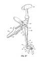
- the first positioning tool 50can be modified to provide for connection of the first positioning tool 50 to the vertebral anchor 14 outside the patient, the first positioning tool 50 and vertebral anchor 14 inserted through the incision 30 as a single unit.
- the first positioning tool 50can be used to guide the vertebral anchor 14 to the vertebral body 18 for securement to the vertebral body.
- a k-wire(not shown) that is secured to the vertebral body 18 can be used in connection with a cannulated vertebral anchor 14 to assist in proper securement and positioning of the vertebral anchor 14 .
- This method of securement of vertebral anchors to vertebral bodiesmay be used for any vertebral anchor used in the stabilization system 10 .
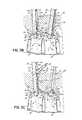
- the connecting element 22may be provided with an end portion 71 that is more rigid than the remainder of the connecting element 22 . This may be achieved by constructing the connecting element 22 with different material properties at the end portion 71 or by mounting a separate component to the connecting element 22 .
- the end portion 71may be a bullet-shaped nose or similar structure coupled to the connecting element 22 .
- the nosemay be constructed of metal or other rigid material and may be tapered to a tip 73 to facilitate movement through tissue.
- the material of the end portion 71may also be selected to help identify the location of the end portion 71 as the connecting element 22 is advanced through tissue.
- the end portion 71may be constructed from radiopaque material so as to serve as a marker during a surgical procedure.
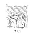
- the threaded engagementsecures the second portion 96 of the connecting element 22 relative to the first vertebral anchor 14 .
- the connecting element 22may then be cut proximate the first vertebral anchor 14 , and the first positioning tool 50 and the tensioning tool 150 may be removed from the patient's body 12 through the first incision 30 . This results in the arrangement shown in FIG. 3G .
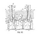
- the first delivery device 500 and the first portion 74 of the connecting element 22may be inserted through the third incision 304 and along at least a portion of the third positioning tool 306 .
- the third positioning tool 306may be used for guidance and/or leverage to help direct the first delivery device 500 and first portion 74 along a path through the patient's body 12 and generally toward the first vertebral anchor 14 .
- the third positioning tool 306 and its elongated slotmay be used in a way similar to which the first positioning tool 50 and elongated slot 58 are used in the other embodiments discussed above.
- the first delivery device 500 contacts the first vertebral anchor 14 and/or first positioning tool 50it may be directed upwardly toward the first incision 30 .
Landscapes
- Health & Medical Sciences (AREA)
- Orthopedic Medicine & Surgery (AREA)
- Life Sciences & Earth Sciences (AREA)
- Surgery (AREA)
- Neurology (AREA)
- Heart & Thoracic Surgery (AREA)
- Engineering & Computer Science (AREA)
- Biomedical Technology (AREA)
- Nuclear Medicine, Radiotherapy & Molecular Imaging (AREA)
- Medical Informatics (AREA)
- Molecular Biology (AREA)
- Animal Behavior & Ethology (AREA)
- General Health & Medical Sciences (AREA)
- Public Health (AREA)
- Veterinary Medicine (AREA)
- Surgical Instruments (AREA)
- Prostheses (AREA)
Abstract
Description
Claims (19)
Priority Applications (10)
| Application Number | Priority Date | Filing Date | Title |
|---|---|---|---|
| US12/025,984US9277940B2 (en) | 2008-02-05 | 2008-02-05 | System and method for insertion of flexible spinal stabilization element |
| CA2715243ACA2715243A1 (en) | 2008-02-05 | 2008-11-26 | System and method for insertion of flexible spinal stabilization element |
| CN2008801284342ACN102014776A (en) | 2008-02-05 | 2008-11-26 | System and method for insertion of flexible spinal stabilization element |
| AU2008349784AAU2008349784A1 (en) | 2008-02-05 | 2008-11-26 | System and method for insertion of flexible spinal stabilization element |
| EP08872028AEP2254494B1 (en) | 2008-02-05 | 2008-11-26 | System for insertion of flexible spinal stabilization element |
| PCT/US2008/085002WO2009099477A2 (en) | 2008-02-05 | 2008-11-26 | System and method for insertion of flexible spinal stabilization element |
| US29/330,097USD620109S1 (en) | 2008-02-05 | 2008-12-29 | Surgical installation tool |
| US14/800,309US9782203B2 (en) | 2008-02-05 | 2015-07-15 | System and method for insertion of flexible spinal stabilization element |
| US15/718,052US10603079B2 (en) | 2008-02-05 | 2017-09-28 | System and method for insertion of flexible spinal stabilization element |
| US16/788,991US10856910B2 (en) | 2008-02-05 | 2020-02-12 | System and method for insertion of flexible spinal stabilization element |
Applications Claiming Priority (1)
| Application Number | Priority Date | Filing Date | Title |
|---|---|---|---|
| US12/025,984US9277940B2 (en) | 2008-02-05 | 2008-02-05 | System and method for insertion of flexible spinal stabilization element |
Related Child Applications (2)
| Application Number | Title | Priority Date | Filing Date |
|---|---|---|---|
| US29/330,097Continuation-In-PartUSD620109S1 (en) | 2008-02-05 | 2008-12-29 | Surgical installation tool |
| US14/800,309ContinuationUS9782203B2 (en) | 2008-02-05 | 2015-07-15 | System and method for insertion of flexible spinal stabilization element |
Publications (2)
| Publication Number | Publication Date |
|---|---|
| US20090198281A1 US20090198281A1 (en) | 2009-08-06 |
| US9277940B2true US9277940B2 (en) | 2016-03-08 |
Family
ID=40932426
Family Applications (4)
| Application Number | Title | Priority Date | Filing Date |
|---|---|---|---|
| US12/025,984Active2033-08-31US9277940B2 (en) | 2008-02-05 | 2008-02-05 | System and method for insertion of flexible spinal stabilization element |
| US14/800,309Active2028-02-23US9782203B2 (en) | 2008-02-05 | 2015-07-15 | System and method for insertion of flexible spinal stabilization element |
| US15/718,052ActiveUS10603079B2 (en) | 2008-02-05 | 2017-09-28 | System and method for insertion of flexible spinal stabilization element |
| US16/788,991ActiveUS10856910B2 (en) | 2008-02-05 | 2020-02-12 | System and method for insertion of flexible spinal stabilization element |
Family Applications After (3)
| Application Number | Title | Priority Date | Filing Date |
|---|---|---|---|
| US14/800,309Active2028-02-23US9782203B2 (en) | 2008-02-05 | 2015-07-15 | System and method for insertion of flexible spinal stabilization element |
| US15/718,052ActiveUS10603079B2 (en) | 2008-02-05 | 2017-09-28 | System and method for insertion of flexible spinal stabilization element |
| US16/788,991ActiveUS10856910B2 (en) | 2008-02-05 | 2020-02-12 | System and method for insertion of flexible spinal stabilization element |
Country Status (6)
| Country | Link |
|---|---|
| US (4) | US9277940B2 (en) |
| EP (1) | EP2254494B1 (en) |
| CN (1) | CN102014776A (en) |
| AU (1) | AU2008349784A1 (en) |
| CA (1) | CA2715243A1 (en) |
| WO (1) | WO2009099477A2 (en) |
Cited By (6)
| Publication number | Priority date | Publication date | Assignee | Title |
|---|---|---|---|---|
| US20140330318A1 (en)* | 2008-12-12 | 2014-11-06 | Zimmer Spine, Inc. | Spinal stabilization installation instrumentation and methods |
| US20170265911A1 (en)* | 2003-11-08 | 2017-09-21 | Stryker European Holdings I, Llc | Methods and devices for improving percutaneous access in minimally invasive surgeries |
| US9782203B2 (en) | 2008-02-05 | 2017-10-10 | Zimmer Spine, Inc. | System and method for insertion of flexible spinal stabilization element |
| US20190059959A1 (en)* | 2017-08-29 | 2019-02-28 | Zimmer Biomet Spine, Inc. | Surgical cord tensioning devices, systems, and methods |
| WO2020077029A1 (en)* | 2018-10-10 | 2020-04-16 | Zimmer Biomet Spine, Inc. | Surgical cord tensioning devices and systems |
| US10905474B2 (en) | 2017-08-29 | 2021-02-02 | Zimmer Biomet Spine, Inc. | Surgical cord tensioning devices, systems, and methods |
Families Citing this family (71)
| Publication number | Priority date | Publication date | Assignee | Title |
|---|---|---|---|---|
| US7833250B2 (en) | 2004-11-10 | 2010-11-16 | Jackson Roger P | Polyaxial bone screw with helically wound capture connection |
| US7862587B2 (en) | 2004-02-27 | 2011-01-04 | Jackson Roger P | Dynamic stabilization assemblies, tool set and method |
| US10729469B2 (en) | 2006-01-09 | 2020-08-04 | Roger P. Jackson | Flexible spinal stabilization assembly with spacer having off-axis core member |
| US10258382B2 (en) | 2007-01-18 | 2019-04-16 | Roger P. Jackson | Rod-cord dynamic connection assemblies with slidable bone anchor attachment members along the cord |
| US8353932B2 (en) | 2005-09-30 | 2013-01-15 | Jackson Roger P | Polyaxial bone anchor assembly with one-piece closure, pressure insert and plastic elongate member |
| US8292926B2 (en) | 2005-09-30 | 2012-10-23 | Jackson Roger P | Dynamic stabilization connecting member with elastic core and outer sleeve |
| US8876868B2 (en) | 2002-09-06 | 2014-11-04 | Roger P. Jackson | Helical guide and advancement flange with radially loaded lip |
| US7621918B2 (en) | 2004-11-23 | 2009-11-24 | Jackson Roger P | Spinal fixation tool set and method |
| US7377923B2 (en) | 2003-05-22 | 2008-05-27 | Alphatec Spine, Inc. | Variable angle spinal screw assembly |
| US7776067B2 (en) | 2005-05-27 | 2010-08-17 | Jackson Roger P | Polyaxial bone screw with shank articulation pressure insert and method |
| US8092500B2 (en) | 2007-05-01 | 2012-01-10 | Jackson Roger P | Dynamic stabilization connecting member with floating core, compression spacer and over-mold |
| US7766915B2 (en) | 2004-02-27 | 2010-08-03 | Jackson Roger P | Dynamic fixation assemblies with inner core and outer coil-like member |
| US8366753B2 (en) | 2003-06-18 | 2013-02-05 | Jackson Roger P | Polyaxial bone screw assembly with fixed retaining structure |
| US8926670B2 (en) | 2003-06-18 | 2015-01-06 | Roger P. Jackson | Polyaxial bone screw assembly |
| US7967850B2 (en) | 2003-06-18 | 2011-06-28 | Jackson Roger P | Polyaxial bone anchor with helical capture connection, insert and dual locking assembly |
| US7179261B2 (en) | 2003-12-16 | 2007-02-20 | Depuy Spine, Inc. | Percutaneous access devices and bone anchor assemblies |
| US7527638B2 (en) | 2003-12-16 | 2009-05-05 | Depuy Spine, Inc. | Methods and devices for minimally invasive spinal fixation element placement |
| US11419642B2 (en) | 2003-12-16 | 2022-08-23 | Medos International Sarl | Percutaneous access devices and bone anchor assemblies |
| JP2007525274A (en) | 2004-02-27 | 2007-09-06 | ロジャー・ピー・ジャクソン | Orthopedic implant rod reduction instrument set and method |
| US7160300B2 (en) | 2004-02-27 | 2007-01-09 | Jackson Roger P | Orthopedic implant rod reduction tool set and method |
| US11241261B2 (en) | 2005-09-30 | 2022-02-08 | Roger P Jackson | Apparatus and method for soft spinal stabilization using a tensionable cord and releasable end structure |
| US8152810B2 (en)* | 2004-11-23 | 2012-04-10 | Jackson Roger P | Spinal fixation tool set and method |
| US7651502B2 (en) | 2004-09-24 | 2010-01-26 | Jackson Roger P | Spinal fixation tool set and method for rod reduction and fastener insertion |
| US8926672B2 (en) | 2004-11-10 | 2015-01-06 | Roger P. Jackson | Splay control closure for open bone anchor |
| US8444681B2 (en) | 2009-06-15 | 2013-05-21 | Roger P. Jackson | Polyaxial bone anchor with pop-on shank, friction fit retainer and winged insert |
| US9168069B2 (en) | 2009-06-15 | 2015-10-27 | Roger P. Jackson | Polyaxial bone anchor with pop-on shank and winged insert with lower skirt for engaging a friction fit retainer |
| WO2006057837A1 (en) | 2004-11-23 | 2006-06-01 | Jackson Roger P | Spinal fixation tool attachment structure |
| US9216041B2 (en) | 2009-06-15 | 2015-12-22 | Roger P. Jackson | Spinal connecting members with tensioned cords and rigid sleeves for engaging compression inserts |
| US7901437B2 (en) | 2007-01-26 | 2011-03-08 | Jackson Roger P | Dynamic stabilization member with molded connection |
| WO2007038429A1 (en) | 2005-09-27 | 2007-04-05 | Endius, Inc. | Methods and apparatuses for stabilizing the spine through an access device |
| US8105368B2 (en) | 2005-09-30 | 2012-01-31 | Jackson Roger P | Dynamic stabilization connecting member with slitted core and outer sleeve |
| CA2670988C (en) | 2006-12-08 | 2014-03-25 | Roger P. Jackson | Tool system for dynamic spinal implants |
| US8475498B2 (en) | 2007-01-18 | 2013-07-02 | Roger P. Jackson | Dynamic stabilization connecting member with cord connection |
| US8366745B2 (en) | 2007-05-01 | 2013-02-05 | Jackson Roger P | Dynamic stabilization assembly having pre-compressed spacers with differential displacements |
| US8979904B2 (en) | 2007-05-01 | 2015-03-17 | Roger P Jackson | Connecting member with tensioned cord, low profile rigid sleeve and spacer with torsion control |
| US10383660B2 (en) | 2007-05-01 | 2019-08-20 | Roger P. Jackson | Soft stabilization assemblies with pretensioned cords |
| AU2010260521C1 (en) | 2008-08-01 | 2013-08-01 | Roger P. Jackson | Longitudinal connecting member with sleeved tensioned cords |
| US8998959B2 (en) | 2009-06-15 | 2015-04-07 | Roger P Jackson | Polyaxial bone anchors with pop-on shank, fully constrained friction fit retainer and lock and release insert |
| US11229457B2 (en) | 2009-06-15 | 2022-01-25 | Roger P. Jackson | Pivotal bone anchor assembly with insert tool deployment |
| CN103826560A (en) | 2009-06-15 | 2014-05-28 | 罗杰.P.杰克逊 | Polyaxial Bone Anchor with Socket Stem and Winged Inserts with Friction Fit Compression Collars |
| US9668771B2 (en) | 2009-06-15 | 2017-06-06 | Roger P Jackson | Soft stabilization assemblies with off-set connector |
| US20110009906A1 (en)* | 2009-07-13 | 2011-01-13 | Zimmer Spine, Inc. | Vertebral stabilization transition connector |
| US9211144B2 (en)* | 2009-09-09 | 2015-12-15 | Globus Medical, Inc. | Spine surgery device and method |
| EP2485654B1 (en) | 2009-10-05 | 2021-05-05 | Jackson P. Roger | Polyaxial bone anchor with non-pivotable retainer and pop-on shank, some with friction fit |
| US8328849B2 (en)* | 2009-12-01 | 2012-12-11 | Zimmer Gmbh | Cord for vertebral stabilization system |
| US8740945B2 (en) | 2010-04-07 | 2014-06-03 | Zimmer Spine, Inc. | Dynamic stabilization system using polyaxial screws |
| US8382803B2 (en) | 2010-08-30 | 2013-02-26 | Zimmer Gmbh | Vertebral stabilization transition connector |
| AU2011299558A1 (en) | 2010-09-08 | 2013-05-02 | Roger P. Jackson | Dynamic stabilization members with elastic and inelastic sections |
| US8968319B2 (en) | 2011-06-20 | 2015-03-03 | Spinefrontier, Inc | Methods, tools and devices for spinal fixation |
| US8911479B2 (en) | 2012-01-10 | 2014-12-16 | Roger P. Jackson | Multi-start closures for open implants |
| US8911478B2 (en) | 2012-11-21 | 2014-12-16 | Roger P. Jackson | Splay control closure for open bone anchor |
| US10058354B2 (en) | 2013-01-28 | 2018-08-28 | Roger P. Jackson | Pivotal bone anchor assembly with frictional shank head seating surfaces |
| US8852239B2 (en) | 2013-02-15 | 2014-10-07 | Roger P Jackson | Sagittal angle screw with integral shank and receiver |
| US9554835B2 (en) | 2013-03-14 | 2017-01-31 | Warsaw Orthopedic, Inc. | Surgical implant system and method |
| US9387018B2 (en) | 2013-03-14 | 2016-07-12 | Warsaw Orthopedic, Inc. | Surgical implant system and method |
| EP2967653B1 (en)* | 2013-03-15 | 2019-05-29 | Shriners Hospitals for Children | Techniques for spinal surgery |
| US9566092B2 (en) | 2013-10-29 | 2017-02-14 | Roger P. Jackson | Cervical bone anchor with collet retainer and outer locking sleeve |
| US9717533B2 (en) | 2013-12-12 | 2017-08-01 | Roger P. Jackson | Bone anchor closure pivot-splay control flange form guide and advancement structure |
| US9451993B2 (en) | 2014-01-09 | 2016-09-27 | Roger P. Jackson | Bi-radial pop-on cervical bone anchor |
| US9597119B2 (en) | 2014-06-04 | 2017-03-21 | Roger P. Jackson | Polyaxial bone anchor with polymer sleeve |
| US10064658B2 (en) | 2014-06-04 | 2018-09-04 | Roger P. Jackson | Polyaxial bone anchor with insert guides |
| US9724131B2 (en) | 2014-09-25 | 2017-08-08 | DePuy Synthes Products, Inc. | Spinal connectors and related methods |
| CA3008161C (en) | 2014-12-09 | 2023-09-26 | John A. Heflin | Spine alignment system |
| US9924983B2 (en)* | 2015-02-11 | 2018-03-27 | Warsaw Orthopedic, Inc. | Spinal correction method and system |
| CN106361413A (en)* | 2015-07-24 | 2017-02-01 | 镱钛科技股份有限公司 | Puncture guide |
| EP4368128A3 (en) | 2016-09-07 | 2024-07-17 | Vertos Medical, Inc. | Percutaneous lateral recess resection methods and instruments |
| US10456174B2 (en) | 2017-07-31 | 2019-10-29 | Medos International Sarl | Connectors for use in systems and methods for reducing the risk of proximal junctional kyphosis |
| US10463403B2 (en)* | 2017-07-31 | 2019-11-05 | Medos International Sarl | Systems and methods for reducing the risk of proximal junctional kyphosis using a bone anchor or other attachment point |
| US11020149B2 (en)* | 2018-02-28 | 2021-06-01 | Globus Medical Inc. | Scoliosis correction systems, methods, and instruments |
| US11389204B2 (en) | 2020-12-17 | 2022-07-19 | Institute For Spine & Scoliosis, P.A. | Method for improved spinal correction surgery implementing non-fusion anterior scoliosis correction techniques for release of discs |
| US20230404561A1 (en) | 2022-06-16 | 2023-12-21 | Vertos Medical, Inc. | Integrated instrument assembly |
Citations (145)
| Publication number | Priority date | Publication date | Assignee | Title |
|---|---|---|---|---|
| US2248054A (en) | 1939-06-07 | 1941-07-08 | Becker Joseph | Screw driver |
| NL7610576A (en) | 1976-09-23 | 1978-03-29 | Gerard Hendrik Slot | Spinal column repositioning system - uses tongs to position screws in column sections before securing to rope |
| US4526067A (en) | 1982-02-17 | 1985-07-02 | Societe Nationale Industrielle Et Aerospatiale | Automatic mounting appliance for assembling means |
| WO1989000028A1 (en) | 1987-07-08 | 1989-01-12 | Lutz Biedermann | Positioning device |
| US4862774A (en) | 1987-02-24 | 1989-09-05 | Else Frederick A | Screw holder |
| WO1990000377A1 (en) | 1988-07-13 | 1990-01-25 | Harms Juergen | Correction and restraining device, in particular for the vertebral column |
| US4946458A (en) | 1986-04-25 | 1990-08-07 | Harms Juergen | Pedicle screw |
| WO1991006254A1 (en) | 1989-11-03 | 1991-05-16 | Lutz Biedermann | Pedicel screw, and correction and retaining device with said pedicel screw |
| US5030220A (en) | 1990-03-29 | 1991-07-09 | Advanced Spine Fixation Systems Incorporated | Spine fixation system |
| WO1991016020A1 (en) | 1990-04-26 | 1991-10-31 | Danninger Medical Technology, Inc. | Transpedicular screw system and method of use |
| WO1992020294A1 (en) | 1991-05-18 | 1992-11-26 | Eisenstein, Stephen, Michael, Fels | Spinal fixation system |
| WO1993011715A1 (en) | 1991-12-12 | 1993-06-24 | Jbs Sa | Improvements relating to processes and devices for straightening, clamping, compressing and stretching the spine |
| US5261913A (en) | 1989-07-26 | 1993-11-16 | J.B.S. Limited Company | Device for straightening, securing, compressing and elongating the spinal column |
| WO1994017745A1 (en) | 1993-02-09 | 1994-08-18 | Plus Endoprothetik Ag | Device for stiffening and/or correcting the spine |
| WO1994014384A3 (en) | 1992-12-23 | 1994-08-18 | Plus Endoprothetik Ag | System for osteosynthesis along the spinal column, connecting element for such a system and tool for assembling and/or dismantling the same |
| WO1995001132A1 (en) | 1993-07-02 | 1995-01-12 | Synthes Ag, Chur | Posterior vertebral column implant |
| WO1995013755A1 (en) | 1993-11-19 | 1995-05-26 | Cross Medical Products, Inc. | Rod anchor seat having sliding closure member |
| WO1995013756A1 (en) | 1993-11-19 | 1995-05-26 | Cross Medical Products, Inc. | Spine rod anchors, spine rod connectors and nut alignment guide |
| WO1995014437A1 (en) | 1993-11-25 | 1995-06-01 | Sofamor Danek Group, Inc. | Implant for an osteosynthesis device, particularly for the spine, and positioning instrument therefor |
| WO1995019149A1 (en) | 1994-01-18 | 1995-07-20 | Safir S.A.R.L. | Global vertebral fixation device |
| EP0669109A1 (en) | 1994-02-28 | 1995-08-30 | SULZER Medizinaltechnik AG | Stabilizer for adjacent vertebrae |
| US5458030A (en) | 1992-11-04 | 1995-10-17 | Betts; Geoffrey | Screwdrivers |
| US5540688A (en) | 1991-05-30 | 1996-07-30 | Societe "Psi" | Intervertebral stabilization device incorporating dampers |
| US5584831A (en) | 1993-07-09 | 1996-12-17 | September 28, Inc. | Spinal fixation device and method |
| US5672176A (en) | 1995-03-15 | 1997-09-30 | Biedermann; Lutz | Anchoring member |
| US5681319A (en) | 1995-03-01 | 1997-10-28 | Biedermann; Lutz | Locking tool |
| WO1998012977A1 (en) | 1996-09-24 | 1998-04-02 | Sdgi Holdings, Inc. | Multi-axial bone screw assembly |
| WO1999005980A1 (en) | 1997-07-31 | 1999-02-11 | Plus Endoprothetik Ag | Device for stiffening and/or correcting a vertebral column or such like |
| US5989254A (en) | 1997-05-20 | 1999-11-23 | Katz; Akiva Raphael | Pedicle screw assembly |
| WO2000027297A1 (en) | 1998-11-09 | 2000-05-18 | Sdgi Holdings, Inc. | Reverse angle thread for preventing splaying in medical devices |
| US6112623A (en) | 1997-05-30 | 2000-09-05 | Sofamor S.N.C. | Tool for screwing a screw having two threaded portions separated by an intermediate screwing portion |
| US6139549A (en) | 1996-04-09 | 2000-10-31 | Waldemar Link (Gmbh & Co.) | Spinal fixing device |
| WO2001001873A1 (en) | 1999-07-01 | 2001-01-11 | Spinevision S.A. | Fixing element and ancillary for stabilising vertebrae |
| US6183472B1 (en) | 1998-04-09 | 2001-02-06 | Howmedica Gmbh | Pedicle screw and an assembly aid therefor |
| US6224598B1 (en) | 2000-02-16 | 2001-05-01 | Roger P. Jackson | Bone screw threaded plug closure with central set screw |
| US20010007074A1 (en) | 1999-12-23 | 2001-07-05 | Michael Strobel | Screw for medical purposes and a driving tool |
| US20010012937A1 (en) | 2000-02-07 | 2001-08-09 | Ulrich Gmbh & Co. Kg | Polyaxial pedicle screw |
| US20020035366A1 (en)* | 2000-09-18 | 2002-03-21 | Reto Walder | Pedicle screw for intervertebral support elements |
| US20020058942A1 (en) | 2000-11-10 | 2002-05-16 | Biedermann Motech Gmbh | Bone screw |
| US20020082602A1 (en) | 2000-12-22 | 2002-06-27 | Lutz Biedermann | Fixing element |
| US20020082598A1 (en) | 2000-06-23 | 2002-06-27 | Teitelbaum George P. | Percutaneous vertebral fusion system |
| US20020116001A1 (en) | 2001-02-17 | 2002-08-22 | Bernd Schafer | Bone screw |
| WO2002069854A1 (en) | 2001-03-06 | 2002-09-12 | Sung-Kon Kim | Screw for fixing spine |
| US20020133159A1 (en) | 2000-12-08 | 2002-09-19 | Jackson Roger P. | Closure for open-headed medical implant |
| US20020133154A1 (en) | 2001-03-15 | 2002-09-19 | Saint Martin Pierre Henri | Anchoring member with safety ring |
| US20020138076A1 (en) | 2000-12-27 | 2002-09-26 | Biederman Motech Gmbh | Screw |
| US20020143341A1 (en) | 2001-03-27 | 2002-10-03 | Lutz Biedermann | Anchoring element |
| US6471705B1 (en) | 1999-08-02 | 2002-10-29 | Lutz Biedermann | Bone screw |
| US20030018342A1 (en) | 2000-03-28 | 2003-01-23 | Showa Ika Kohgyo Co., Ltd. | Spinal implant, driver tool and nut guide |
| US20030023243A1 (en) | 2001-07-27 | 2003-01-30 | Biedermann Motech Gmbh | Bone screw and fastening tool for same |
| US6530929B1 (en) | 1999-10-20 | 2003-03-11 | Sdgi Holdings, Inc. | Instruments for stabilization of bony structures |
| US6565565B1 (en) | 1998-06-17 | 2003-05-20 | Howmedica Osteonics Corp. | Device for securing spinal rods |
| US20030100896A1 (en) | 2001-11-27 | 2003-05-29 | Lutz Biedermann | Element with a shank and a holding element connected to it for connecting to a rod |
| US20030100904A1 (en) | 2001-11-27 | 2003-05-29 | Lutz Biedermann | Locking device for securing a rod-shaped element in a holding element connected to a shank |
| US20030114860A1 (en) | 1999-12-03 | 2003-06-19 | Remi Cavagna | Tighening instrument for orthopaedic surgery of the spine |
| US6585737B1 (en) | 1998-04-30 | 2003-07-01 | Stryker Spine | Backbone osteosynthesis system with collar and lock |
| US20030125741A1 (en) | 2001-12-28 | 2003-07-03 | Biedermann Motech Gmbh | Locking device for securing a rod-shaped element in a holding element connected to a shank |
| US20030187439A1 (en) | 2002-03-27 | 2003-10-02 | Biedermann Motech Gmbh | Bone anchoring device for stabilizing bone segments and seat part of a bone anchoring device |
| US6648888B1 (en)* | 2002-09-06 | 2003-11-18 | Endius Incorporated | Surgical instrument for moving a vertebra |
| US6652526B1 (en) | 2001-10-05 | 2003-11-25 | Ruben P. Arafiles | Spinal stabilization rod fastener |
| WO2004004549A2 (en) | 2002-07-10 | 2004-01-15 | Joseph Aferzon | Spinal support coupling device |
| FR2844180A1 (en) | 2002-09-11 | 2004-03-12 | Spinevision | Connection element for spinal fixation system designed to link at least two implantable connection assemblies, is formed from a helicoidal spring part and a polymeric material support part |
| US6726687B2 (en) | 2000-12-08 | 2004-04-27 | Jackson Roger P | Closure plug for open-headed medical implant |
| US6730093B2 (en) | 2001-03-15 | 2004-05-04 | Stryker Spine | Anchoring member with packer |
| US6730089B2 (en) | 2002-08-26 | 2004-05-04 | Roger P. Jackson | Nested closure plug and set screw with break-off heads |
| US20040097933A1 (en) | 2002-11-19 | 2004-05-20 | Rodolphe Lourdel | Vertebral anchoring device and its blocking device on a polyaxial screw |
| WO2004041100A1 (en) | 2002-10-30 | 2004-05-21 | Spinal Concepts, Inc. | Spinal stabilization system insertion and methods |
| US20040102781A1 (en) | 2002-11-25 | 2004-05-27 | U & I Corporation | Bone fixation apparatus, method and tool for assembling the same |
| US20040122425A1 (en) | 2002-09-12 | 2004-06-24 | Showa Ika Kohgyo Co., Ltd. | Rod fixing apparatus for vertebra connecting member |
| US20040143264A1 (en)* | 2002-08-23 | 2004-07-22 | Mcafee Paul C. | Metal-backed UHMWPE rod sleeve system preserving spinal motion |
| US20040176766A1 (en) | 2002-02-13 | 2004-09-09 | Shluzas Alan E. | Apparatus for connecting a longitudinal member to a bone portion |
| US20040181224A1 (en) | 2003-03-11 | 2004-09-16 | Biedermann Motech Gmbh | Anchoring element for use in spine or bone surgery, methods for use and production thereof |
| US20040186474A1 (en) | 2002-12-02 | 2004-09-23 | Biedermann Motech Gmbh | Implant having a shaft and a holding element connected therewith for connecting with a rod |
| US20040215190A1 (en) | 2003-04-25 | 2004-10-28 | Nguyen Thanh V. | System and method for minimally invasive posterior fixation |
| US20040225289A1 (en) | 2003-05-07 | 2004-11-11 | Biedermann Motech Gmbh | Dynamic anchoring device and dynamic stabilization device for bones, in particular for vertebrae, with such an anchoring device |
| US20040243193A1 (en) | 2003-05-30 | 2004-12-02 | Ballis Joseph J. | Electromagnetic interference alarm |
| US20040249378A1 (en) | 2001-10-04 | 2004-12-09 | Saint Martin Pierre Henri | Spinal osteosynthesis assembly comprising the head of an anchoring member and a tool for fixing said head |
| US20050010220A1 (en)* | 2003-04-24 | 2005-01-13 | Simon Casutt | Instrument system for pedicle screws |
| US20050055026A1 (en) | 2002-10-02 | 2005-03-10 | Biedermann Motech Gmbh | Bone anchoring element |
| US20050065526A1 (en) | 2001-12-04 | 2005-03-24 | Tim Drew | Fixing device and applicator therefor |
| US20050065516A1 (en) | 2003-09-24 | 2005-03-24 | Tae-Ahn Jahng | Method and apparatus for flexible fixation of a spine |
| EP1523949A1 (en) | 2003-10-17 | 2005-04-20 | BIEDERMANN MOTECH GmbH | Surgical rod element, stabilisation device, and method of manufacturing the element |
| US6896677B1 (en) | 2003-12-11 | 2005-05-24 | A-Spine Holding Group Corp. | Rotary device for retrieving spinal column under treatment |
| US20050124991A1 (en) | 2003-12-05 | 2005-06-09 | Tae-Ahn Jahng | Method and apparatus for flexible fixation of a spine |
| US6905500B2 (en) | 2001-10-31 | 2005-06-14 | U & I Corporation | Bone fixation apparatus |
| US20050131407A1 (en)* | 2003-12-16 | 2005-06-16 | Sicvol Christopher W. | Flexible spinal fixation elements |
| US20050131421A1 (en) | 2003-12-16 | 2005-06-16 | Anderson David G. | Methods and devices for minimally invasive spinal fixation element placement |
| US20050143737A1 (en) | 2003-12-31 | 2005-06-30 | John Pafford | Dynamic spinal stabilization system |
| US20050149053A1 (en) | 2003-12-17 | 2005-07-07 | Varieur Michael S. | Instruments and methods for bone anchor engagement and spinal rod reduction |
| US20050154390A1 (en) | 2003-11-07 | 2005-07-14 | Lutz Biedermann | Stabilization device for bones comprising a spring element and manufacturing method for said spring element |
| US20050192589A1 (en)* | 2004-02-06 | 2005-09-01 | Douglas Raymond | Devices and methods for inserting a spinal fixation element |
| US20050192579A1 (en) | 2004-02-27 | 2005-09-01 | Jackson Roger P. | Orthopedic implant rod reduction tool set and method |
| FR2867057A1 (en) | 2004-03-02 | 2005-09-09 | Spinevision | Connecting element, useful for a spinal fixing system to connect two entire implantable connection bodies comprises a cable and a polymer envelope surrounding the cable |
| US20050203514A1 (en) | 2003-09-24 | 2005-09-15 | Tae-Ahn Jahng | Adjustable spinal stabilization system |
| US20050203513A1 (en) | 2003-09-24 | 2005-09-15 | Tae-Ahn Jahng | Spinal stabilization device |
| US20050234451A1 (en) | 2004-04-16 | 2005-10-20 | Markworth Aaron D | Pedicle screw assembly |
| US20050267472A1 (en) | 2002-03-27 | 2005-12-01 | Biedermann Motech Gmbh | Bone anchoring device for stabilising bone segments and seat part of a bone anchoring device |
| US20050277925A1 (en) | 2004-06-09 | 2005-12-15 | Mujwid James R | Spinal fixation device with internal drive structure |
| US20050277922A1 (en)* | 2004-06-09 | 2005-12-15 | Trieu Hai H | Systems and methods for flexible spinal stabilization |
| US6986771B2 (en) | 2003-05-23 | 2006-01-17 | Globus Medical, Inc. | Spine stabilization system |
| US6994710B2 (en) | 2001-05-09 | 2006-02-07 | Patrick Michel White | Surgical driver |
| US20060036255A1 (en) | 2004-08-13 | 2006-02-16 | Pond John D Jr | System and method for positioning a connecting member adjacent the spinal column in minimally invasive procedures |
| US20060074418A1 (en)* | 2004-09-24 | 2006-04-06 | Jackson Roger P | Spinal fixation tool set and method for rod reduction and fastener insertion |
| US20060089644A1 (en) | 2004-10-27 | 2006-04-27 | Felix Brent A | Spinal stabilizing system |
| US20060111712A1 (en) | 2004-11-23 | 2006-05-25 | Jackson Roger P | Spinal fixation tool set and method |
| US20060111715A1 (en)* | 2004-02-27 | 2006-05-25 | Jackson Roger P | Dynamic stabilization assemblies, tool set and method |
| US20060122602A1 (en) | 2004-12-08 | 2006-06-08 | Depuy Spine, Inc. | Hybrid spinal plates |
| WO2006066685A1 (en) | 2004-12-17 | 2006-06-29 | Zimmer Gmbh | Intervertebral stabilisation system |
| US20060149242A1 (en)* | 2004-12-17 | 2006-07-06 | Gary Kraus | Spinal stabilization systems supplemented with diagnostically opaque materials |
| US20060149238A1 (en) | 2005-01-04 | 2006-07-06 | Sherman Michael C | Systems and methods for spinal stabilization with flexible elements |
| US20060155277A1 (en) | 2002-03-21 | 2006-07-13 | Peter Metz-Stavenhagen | Anchoring element for securing a rod of a device for adjusting a human or animal vertrebal column on a vertreba |
| US7081116B1 (en) | 1999-06-14 | 2006-07-25 | Scient'x | Implant for osteosynthesis device in particular of the backbone |
| US20060195086A1 (en) | 2005-02-02 | 2006-08-31 | Syberspine Limited | Integral, articulated, pedicle screw and longitudinal member for spinal osteosynthesis |
| US20060195090A1 (en)* | 2005-02-10 | 2006-08-31 | Loubert Suddaby | Apparatus for and method of aligning a spine |
| US20060217738A1 (en) | 2003-04-16 | 2006-09-28 | Remy Tanimura | Method for reversible fixing of a tool to an implantable element and device for carrying out such a fixing method |
| US20060230887A1 (en) | 2003-06-25 | 2006-10-19 | Yasuaki Taguchi | Bit holder device |
| US20060247630A1 (en)* | 2005-04-27 | 2006-11-02 | Andrew Iott | Percutaneous vertebral stabilization system |
| US20070005063A1 (en)* | 2005-06-20 | 2007-01-04 | Sdgi Holdings, Inc. | Multi-level multi-functional spinal stabilization systems and methods |
| US7160300B2 (en) | 2004-02-27 | 2007-01-09 | Jackson Roger P | Orthopedic implant rod reduction tool set and method |
| US20070016200A1 (en) | 2003-04-09 | 2007-01-18 | Jackson Roger P | Dynamic stabilization medical implant assemblies and methods |
| US7179261B2 (en) | 2003-12-16 | 2007-02-20 | Depuy Spine, Inc. | Percutaneous access devices and bone anchor assemblies |
| US20070042633A1 (en)* | 2004-03-04 | 2007-02-22 | Robert Frigg | Connecting element |
| US20070055244A1 (en) | 2004-02-27 | 2007-03-08 | Jackson Roger P | Dynamic fixation assemblies with inner core and outer coil-like member |
| US20070078460A1 (en)* | 2005-08-25 | 2007-04-05 | Robert Frigg | Methods of spinal fixation and instrumentation |
| US20070191836A1 (en)* | 2006-01-27 | 2007-08-16 | Sdgi Holdings, Inc. | Methods and devices for a minimally invasive placement of a rod within a patient |
| US20070198088A1 (en) | 2003-10-17 | 2007-08-23 | Lutz Biedermann | Flexible implant |
| US20070233075A1 (en)* | 2006-03-16 | 2007-10-04 | Zimmer Spine, Inc. | Spinal fixation device with variable stiffness |
| US20070270860A1 (en)* | 2005-09-30 | 2007-11-22 | Jackson Roger P | Dynamic stabilization connecting member with slitted core and outer sleeve |
| US20070288011A1 (en)* | 2006-04-18 | 2007-12-13 | Joseph Nicholas Logan | Spinal Rod System |
| US20070293862A1 (en) | 2005-09-30 | 2007-12-20 | Jackson Roger P | Dynamic stabilization connecting member with elastic core and outer sleeve |
| US20070299443A1 (en)* | 2006-06-09 | 2007-12-27 | Endius, Inc. | Methods and apparatus for access to and/or treatment of the spine |
| US20080021459A1 (en)* | 2006-07-07 | 2008-01-24 | Warsaw Orthopedic Inc. | Dynamic constructs for spinal stabilization |
| US20080091213A1 (en) | 2004-02-27 | 2008-04-17 | Jackson Roger P | Tool system for dynamic spinal implants |
| US20080140076A1 (en) | 2005-09-30 | 2008-06-12 | Jackson Roger P | Dynamic stabilization connecting member with slitted segment and surrounding external elastomer |
| US20080147122A1 (en) | 2006-10-12 | 2008-06-19 | Jackson Roger P | Dynamic stabilization connecting member with molded inner segment and surrounding external elastomer |
| US20080177317A1 (en)* | 2007-01-18 | 2008-07-24 | Jackson Roger P | Dynamic stabilization connecting member with cord connection |
| US20080183216A1 (en) | 2007-01-26 | 2008-07-31 | Jackson Roger P | Dynamic stabilization member with molded connection |
| US20080234738A1 (en)* | 2007-03-23 | 2008-09-25 | Zimmer Gmbh | System and method for insertion of flexible spinal stabilization element |
| US20080249531A1 (en)* | 2007-02-27 | 2008-10-09 | Warsaw Orthopedic, Inc. | Instruments and methods for minimally invasive insertion of dynamic implants |
| WO2008134703A2 (en) | 2007-04-30 | 2008-11-06 | Globus Medical, Inc. | Flexible spine stabilization system |
| US20080275456A1 (en) | 2007-05-02 | 2008-11-06 | Zimmer Spine, Inc. | Installation systems for spinal stabilization system and related methods |
| US20080294198A1 (en)* | 2006-01-09 | 2008-11-27 | Jackson Roger P | Dynamic spinal stabilization assembly with torsion and shear control |
| US20080300633A1 (en) | 2007-05-31 | 2008-12-04 | Jackson Roger P | Dynamic stabilization connecting member with pre-tensioned solid core |
| US20090012563A1 (en) | 2006-10-11 | 2009-01-08 | Nas Medical Technologies, Inc. | Spinal fixation devices and methods |
| US20090088799A1 (en)* | 2007-10-01 | 2009-04-02 | Chung-Chun Yeh | Spinal fixation device having a flexible cable and jointed components received thereon |
Family Cites Families (28)
| Publication number | Priority date | Publication date | Assignee | Title |
|---|---|---|---|---|
| US5318566A (en)* | 1992-06-22 | 1994-06-07 | Danek Medical, Inc. | Sternotomy cable and method |
| DE50007759D1 (en)* | 1999-11-25 | 2004-10-21 | Sulzer Orthopedics Ltd | Surgical instrument for tensioning a cable-like tensioning element |
| US6783527B2 (en)* | 2001-10-30 | 2004-08-31 | Sdgi Holdings, Inc. | Flexible spinal stabilization system and method |
| US7094240B2 (en)* | 2003-01-10 | 2006-08-22 | Sdgi Holdings, Inc. | Flexible member tensioning instruments and methods |
| DE50301185D1 (en)* | 2003-04-24 | 2005-10-20 | Zimmer Gmbh Winterthur | Distance measuring device for pedicle screws |
| US20070083210A1 (en)* | 2005-09-16 | 2007-04-12 | Zimmer Spine, Inc. | Apparatus and method for minimally invasive spine surgery |
| US20070118119A1 (en)* | 2005-11-18 | 2007-05-24 | Zimmer Spine, Inc. | Methods and device for dynamic stabilization |
| US20080009863A1 (en)* | 2006-06-23 | 2008-01-10 | Zimmer Spine, Inc. | Pedicle screw distractor and associated method of use |
| US9526525B2 (en)* | 2006-08-22 | 2016-12-27 | Neuropro Technologies, Inc. | Percutaneous system for dynamic spinal stabilization |
| US7824430B2 (en) | 2006-12-08 | 2010-11-02 | Warsaw Orthopedic, Inc. | Methods and devices for treating a multi-level spinal deformity |
| US7922725B2 (en)* | 2007-04-19 | 2011-04-12 | Zimmer Spine, Inc. | Method and associated instrumentation for installation of spinal dynamic stabilization system |
| US20080312704A1 (en)* | 2007-06-12 | 2008-12-18 | Zimmer Spine, Inc. | Instrumentation and associated techniques for minimally invasive spinal construct installation |
| US8043343B2 (en)* | 2007-06-28 | 2011-10-25 | Zimmer Spine, Inc. | Stabilization system and method |
| US9039711B2 (en)* | 2007-08-21 | 2015-05-26 | DePuy Synthes Products, Inc. | Instruments and methods for tensioning a spinal tether |
| US8323294B2 (en)* | 2007-08-21 | 2012-12-04 | Depuy Spine, Inc. | Tether tensioning instrument |
| US8540720B2 (en)* | 2007-12-06 | 2013-09-24 | Javier Garcia-Bengochea | System, instrumentation and method for spinal fixation using minimally invasive surgical techniques |
| US9277940B2 (en) | 2008-02-05 | 2016-03-08 | Zimmer Spine, Inc. | System and method for insertion of flexible spinal stabilization element |
| US20090204118A1 (en)* | 2008-02-13 | 2009-08-13 | William Ralph Pratt | Surgical cable with malleable leader segment |
| US8226656B2 (en)* | 2008-04-16 | 2012-07-24 | Warsaw Orthopedic, Inc. | Minimally invasive systems and methods for insertion of a connecting member adjacent the spinal column |
| EP2184023B1 (en)* | 2008-11-07 | 2016-06-29 | Zimmer Spine | A surgical tool for tensioning a flexible member |
| IT1392200B1 (en)* | 2008-12-17 | 2012-02-22 | N B R New Biotechnology Res | MODULAR VERTEBRAL STABILIZER. |
| US8267968B2 (en)* | 2009-06-24 | 2012-09-18 | Neuropro Technologies, Inc. | Percutaneous system for dynamic spinal stabilization |
| US8216245B2 (en)* | 2009-10-30 | 2012-07-10 | Warsaw Orthopedic | Apparatus and method for applying sustained tension on a tether |
| US8328849B2 (en)* | 2009-12-01 | 2012-12-11 | Zimmer Gmbh | Cord for vertebral stabilization system |
| US9339309B1 (en)* | 2012-10-11 | 2016-05-17 | Nuvasive, Inc. | Systems and methods for inserting cross-connectors |
| US20140257416A1 (en)* | 2013-03-06 | 2014-09-11 | Nathan Meyer | Percutaneous rod inserter |
| US10022172B2 (en)* | 2014-06-25 | 2018-07-17 | Spine Wave, Inc. | Minimally invasive posterolateral fusion |
| US9757167B2 (en)* | 2015-03-11 | 2017-09-12 | K2M, Inc. | Inserter and method for securing an implant to a spinal process with a flexible fastening system |
- 2008
- 2008-02-05USUS12/025,984patent/US9277940B2/enactiveActive
- 2008-11-26WOPCT/US2008/085002patent/WO2009099477A2/enactiveApplication Filing
- 2008-11-26AUAU2008349784Apatent/AU2008349784A1/ennot_activeAbandoned
- 2008-11-26EPEP08872028Apatent/EP2254494B1/ennot_activeNot-in-force
- 2008-11-26CACA2715243Apatent/CA2715243A1/ennot_activeAbandoned
- 2008-11-26CNCN2008801284342Apatent/CN102014776A/enactivePending
- 2015
- 2015-07-15USUS14/800,309patent/US9782203B2/enactiveActive
- 2017
- 2017-09-28USUS15/718,052patent/US10603079B2/enactiveActive
- 2020
- 2020-02-12USUS16/788,991patent/US10856910B2/enactiveActive
Patent Citations (193)
| Publication number | Priority date | Publication date | Assignee | Title |
|---|---|---|---|---|
| US2248054A (en) | 1939-06-07 | 1941-07-08 | Becker Joseph | Screw driver |
| NL7610576A (en) | 1976-09-23 | 1978-03-29 | Gerard Hendrik Slot | Spinal column repositioning system - uses tongs to position screws in column sections before securing to rope |
| US4526067A (en) | 1982-02-17 | 1985-07-02 | Societe Nationale Industrielle Et Aerospatiale | Automatic mounting appliance for assembling means |
| US4946458A (en) | 1986-04-25 | 1990-08-07 | Harms Juergen | Pedicle screw |
| US4862774A (en) | 1987-02-24 | 1989-09-05 | Else Frederick A | Screw holder |
| WO1989000028A1 (en) | 1987-07-08 | 1989-01-12 | Lutz Biedermann | Positioning device |
| WO1990000377A1 (en) | 1988-07-13 | 1990-01-25 | Harms Juergen | Correction and restraining device, in particular for the vertebral column |
| US5261913A (en) | 1989-07-26 | 1993-11-16 | J.B.S. Limited Company | Device for straightening, securing, compressing and elongating the spinal column |
| WO1991006254A1 (en) | 1989-11-03 | 1991-05-16 | Lutz Biedermann | Pedicel screw, and correction and retaining device with said pedicel screw |
| US5030220A (en) | 1990-03-29 | 1991-07-09 | Advanced Spine Fixation Systems Incorporated | Spine fixation system |
| US5360431A (en) | 1990-04-26 | 1994-11-01 | Cross Medical Products | Transpedicular screw system and method of use |
| WO1991016020A1 (en) | 1990-04-26 | 1991-10-31 | Danninger Medical Technology, Inc. | Transpedicular screw system and method of use |
| WO1992020294A1 (en) | 1991-05-18 | 1992-11-26 | Eisenstein, Stephen, Michael, Fels | Spinal fixation system |
| US5540688A (en) | 1991-05-30 | 1996-07-30 | Societe "Psi" | Intervertebral stabilization device incorporating dampers |
| WO1993011715A1 (en) | 1991-12-12 | 1993-06-24 | Jbs Sa | Improvements relating to processes and devices for straightening, clamping, compressing and stretching the spine |
| US5458030A (en) | 1992-11-04 | 1995-10-17 | Betts; Geoffrey | Screwdrivers |
| WO1994014384A3 (en) | 1992-12-23 | 1994-08-18 | Plus Endoprothetik Ag | System for osteosynthesis along the spinal column, connecting element for such a system and tool for assembling and/or dismantling the same |
| WO1994017745A1 (en) | 1993-02-09 | 1994-08-18 | Plus Endoprothetik Ag | Device for stiffening and/or correcting the spine |
| US5562660A (en)* | 1993-02-09 | 1996-10-08 | Plus Endoprothetik Ag | Apparatus for stiffening and/or correcting the vertebral column |
| WO1995001132A1 (en) | 1993-07-02 | 1995-01-12 | Synthes Ag, Chur | Posterior vertebral column implant |
| US5584831A (en) | 1993-07-09 | 1996-12-17 | September 28, Inc. | Spinal fixation device and method |
| WO1995013756A1 (en) | 1993-11-19 | 1995-05-26 | Cross Medical Products, Inc. | Spine rod anchors, spine rod connectors and nut alignment guide |
| WO1995013755A1 (en) | 1993-11-19 | 1995-05-26 | Cross Medical Products, Inc. | Rod anchor seat having sliding closure member |
| WO1995014437A1 (en) | 1993-11-25 | 1995-06-01 | Sofamor Danek Group, Inc. | Implant for an osteosynthesis device, particularly for the spine, and positioning instrument therefor |
| FR2715057A1 (en) | 1994-01-18 | 1995-07-21 | Breard Francis Henri | Overall device for stabilizing the spine. |
| WO1995019149A1 (en) | 1994-01-18 | 1995-07-20 | Safir S.A.R.L. | Global vertebral fixation device |
| EP0669109A1 (en) | 1994-02-28 | 1995-08-30 | SULZER Medizinaltechnik AG | Stabilizer for adjacent vertebrae |
| EP0669109B1 (en) | 1994-02-28 | 1999-05-26 | Sulzer Orthopädie AG | Stabilizer for adjacent vertebrae |
| US5681319A (en) | 1995-03-01 | 1997-10-28 | Biedermann; Lutz | Locking tool |
| US5672176A (en) | 1995-03-15 | 1997-09-30 | Biedermann; Lutz | Anchoring member |
| US6139549A (en) | 1996-04-09 | 2000-10-31 | Waldemar Link (Gmbh & Co.) | Spinal fixing device |
| WO1998012977A1 (en) | 1996-09-24 | 1998-04-02 | Sdgi Holdings, Inc. | Multi-axial bone screw assembly |
| US5989254A (en) | 1997-05-20 | 1999-11-23 | Katz; Akiva Raphael | Pedicle screw assembly |
| US6112623A (en) | 1997-05-30 | 2000-09-05 | Sofamor S.N.C. | Tool for screwing a screw having two threaded portions separated by an intermediate screwing portion |
| US6290700B1 (en)* | 1997-07-31 | 2001-09-18 | Plus Endoprothetik Ag | Device for stiffening and/or correcting a vertebral column or such like |
| WO1999005980A1 (en) | 1997-07-31 | 1999-02-11 | Plus Endoprothetik Ag | Device for stiffening and/or correcting a vertebral column or such like |
| US6183472B1 (en) | 1998-04-09 | 2001-02-06 | Howmedica Gmbh | Pedicle screw and an assembly aid therefor |
| US6585737B1 (en) | 1998-04-30 | 2003-07-01 | Stryker Spine | Backbone osteosynthesis system with collar and lock |
| US6565565B1 (en) | 1998-06-17 | 2003-05-20 | Howmedica Osteonics Corp. | Device for securing spinal rods |
| WO2000027297A1 (en) | 1998-11-09 | 2000-05-18 | Sdgi Holdings, Inc. | Reverse angle thread for preventing splaying in medical devices |
| US7081116B1 (en) | 1999-06-14 | 2006-07-25 | Scient'x | Implant for osteosynthesis device in particular of the backbone |
| WO2001001873A1 (en) | 1999-07-01 | 2001-01-11 | Spinevision S.A. | Fixing element and ancillary for stabilising vertebrae |
| US6471705B1 (en) | 1999-08-02 | 2002-10-29 | Lutz Biedermann | Bone screw |
| US20030060826A1 (en)* | 1999-10-20 | 2003-03-27 | Foley Kevin T. | Instruments and methods for stabilization of bony structures |
| US6530929B1 (en) | 1999-10-20 | 2003-03-11 | Sdgi Holdings, Inc. | Instruments for stabilization of bony structures |
| US20030114860A1 (en) | 1999-12-03 | 2003-06-19 | Remi Cavagna | Tighening instrument for orthopaedic surgery of the spine |
| US20010007074A1 (en) | 1999-12-23 | 2001-07-05 | Michael Strobel | Screw for medical purposes and a driving tool |
| US6402752B2 (en) | 2000-02-07 | 2002-06-11 | Ulrich Gmbh & Co. Kg | Polyaxial pedicle-screw |
| US20010012937A1 (en) | 2000-02-07 | 2001-08-09 | Ulrich Gmbh & Co. Kg | Polyaxial pedicle screw |
| US6224598B1 (en) | 2000-02-16 | 2001-05-01 | Roger P. Jackson | Bone screw threaded plug closure with central set screw |
| US6932822B2 (en) | 2000-03-28 | 2005-08-23 | Showa Ika Kohgyo Co., Ltd. | Spinal implant, driver tool and nut guide |
| US20030018342A1 (en) | 2000-03-28 | 2003-01-23 | Showa Ika Kohgyo Co., Ltd. | Spinal implant, driver tool and nut guide |
| US20040087950A1 (en)* | 2000-06-23 | 2004-05-06 | Teitelbaum George P. | Percutaneous vertebral fusion system |
| US7008424B2 (en) | 2000-06-23 | 2006-03-07 | University Of Southern California | Percutaneous vertebral fusion system |
| US20020082598A1 (en) | 2000-06-23 | 2002-06-27 | Teitelbaum George P. | Percutaneous vertebral fusion system |
| US20020035366A1 (en)* | 2000-09-18 | 2002-03-21 | Reto Walder | Pedicle screw for intervertebral support elements |
| US20080243188A1 (en) | 2000-09-18 | 2008-10-02 | Reto Walder | Pedicle screw for intervertebral support elements |
| US20020058942A1 (en) | 2000-11-10 | 2002-05-16 | Biedermann Motech Gmbh | Bone screw |
| US6736820B2 (en) | 2000-11-10 | 2004-05-18 | Biedermann Motech Gmbh | Bone screw |
| US20060106383A1 (en) | 2000-11-10 | 2006-05-18 | Biedermann Motech Gmbh | Bone screw |
| US20040153077A1 (en) | 2000-11-10 | 2004-08-05 | Lutz Biedermann | Bone screw |
| US20060084995A1 (en) | 2000-11-10 | 2006-04-20 | Biedermann Motech Gmbh | Bone screw |
| US20020133159A1 (en) | 2000-12-08 | 2002-09-19 | Jackson Roger P. | Closure for open-headed medical implant |
| US20040186478A1 (en) | 2000-12-08 | 2004-09-23 | Jackson Roger P. | Closure plug for open headed medical implant |
| US6726687B2 (en) | 2000-12-08 | 2004-04-27 | Jackson Roger P | Closure plug for open-headed medical implant |
| US20020082602A1 (en) | 2000-12-22 | 2002-06-27 | Lutz Biedermann | Fixing element |
| US6695843B2 (en) | 2000-12-22 | 2004-02-24 | Biedermann Motech Gmbh | Fixing element |
| US20020138076A1 (en) | 2000-12-27 | 2002-09-26 | Biederman Motech Gmbh | Screw |
| US7018378B2 (en) | 2000-12-27 | 2006-03-28 | Biedermann Motech Gmbh | Screw |
| US6540749B2 (en) | 2001-02-17 | 2003-04-01 | Bernd Schäfer | Bone screw |
| US20020116001A1 (en) | 2001-02-17 | 2002-08-22 | Bernd Schafer | Bone screw |
| WO2002069854A1 (en) | 2001-03-06 | 2002-09-12 | Sung-Kon Kim | Screw for fixing spine |
| US6730093B2 (en) | 2001-03-15 | 2004-05-04 | Stryker Spine | Anchoring member with packer |
| US20020133154A1 (en) | 2001-03-15 | 2002-09-19 | Saint Martin Pierre Henri | Anchoring member with safety ring |
| US20050171542A1 (en) | 2001-03-27 | 2005-08-04 | Lutz Biedermann | Anchoring element |
| US20020143341A1 (en) | 2001-03-27 | 2002-10-03 | Lutz Biedermann | Anchoring element |
| US6835196B2 (en) | 2001-03-27 | 2004-12-28 | Biedermann Motech Gmbh | Anchoring element |
| US6994710B2 (en) | 2001-05-09 | 2006-02-07 | Patrick Michel White | Surgical driver |
| US6723100B2 (en) | 2001-07-27 | 2004-04-20 | Biedermann Motech Gmbh | Bone screw and fastening tool for same |
| US20030023243A1 (en) | 2001-07-27 | 2003-01-30 | Biedermann Motech Gmbh | Bone screw and fastening tool for same |
| US7090679B2 (en) | 2001-10-04 | 2006-08-15 | Pierre Henri Saint-Martin | Spinal osteosynthesis assembly comprising the head of an anchoring member and a tool for fixing said head |
| US20040249378A1 (en) | 2001-10-04 | 2004-12-09 | Saint Martin Pierre Henri | Spinal osteosynthesis assembly comprising the head of an anchoring member and a tool for fixing said head |
| US6652526B1 (en) | 2001-10-05 | 2003-11-25 | Ruben P. Arafiles | Spinal stabilization rod fastener |
| US6905500B2 (en) | 2001-10-31 | 2005-06-14 | U & I Corporation | Bone fixation apparatus |
| US7223268B2 (en) | 2001-11-27 | 2007-05-29 | Biedermann Mötech GmbH | Locking device for securing a rod-shaped element in a holding element connected to a shank |
| US20030100904A1 (en) | 2001-11-27 | 2003-05-29 | Lutz Biedermann | Locking device for securing a rod-shaped element in a holding element connected to a shank |
| US20030100896A1 (en) | 2001-11-27 | 2003-05-29 | Lutz Biedermann | Element with a shank and a holding element connected to it for connecting to a rod |
| US20050065526A1 (en) | 2001-12-04 | 2005-03-24 | Tim Drew | Fixing device and applicator therefor |
| US20030125741A1 (en) | 2001-12-28 | 2003-07-03 | Biedermann Motech Gmbh | Locking device for securing a rod-shaped element in a holding element connected to a shank |
| US7211086B2 (en) | 2001-12-28 | 2007-05-01 | Biedermann Motech Gmbh | Locking device for securing a rod-shaped element in a holding element connected to a shank |
| US20040176766A1 (en) | 2002-02-13 | 2004-09-09 | Shluzas Alan E. | Apparatus for connecting a longitudinal member to a bone portion |
| US7144396B2 (en) | 2002-02-13 | 2006-12-05 | Endius Incorporated | Apparatus for connecting a longitudinal member to a bone portion |
| US20060155277A1 (en) | 2002-03-21 | 2006-07-13 | Peter Metz-Stavenhagen | Anchoring element for securing a rod of a device for adjusting a human or animal vertrebal column on a vertreba |
| US20030187439A1 (en) | 2002-03-27 | 2003-10-02 | Biedermann Motech Gmbh | Bone anchoring device for stabilizing bone segments and seat part of a bone anchoring device |
| US20050267472A1 (en) | 2002-03-27 | 2005-12-01 | Biedermann Motech Gmbh | Bone anchoring device for stabilising bone segments and seat part of a bone anchoring device |
| US6918911B2 (en) | 2002-03-27 | 2005-07-19 | Biedermann Motech Gmbh | Bone anchoring device for stabilizing bone segments and seat part of a bone anchoring device |
| WO2004004549A2 (en) | 2002-07-10 | 2004-01-15 | Joseph Aferzon | Spinal support coupling device |
| US20040143264A1 (en)* | 2002-08-23 | 2004-07-22 | Mcafee Paul C. | Metal-backed UHMWPE rod sleeve system preserving spinal motion |
| US6730089B2 (en) | 2002-08-26 | 2004-05-04 | Roger P. Jackson | Nested closure plug and set screw with break-off heads |
| US6648888B1 (en)* | 2002-09-06 | 2003-11-18 | Endius Incorporated | Surgical instrument for moving a vertebra |
| FR2844180A1 (en) | 2002-09-11 | 2004-03-12 | Spinevision | Connection element for spinal fixation system designed to link at least two implantable connection assemblies, is formed from a helicoidal spring part and a polymeric material support part |
| WO2004024011A1 (en) | 2002-09-11 | 2004-03-25 | Spinevision | Linking element for dynamically stabilizing a spinal fixing system and spinal fixing system comprising same |
| US20060142758A1 (en) | 2002-09-11 | 2006-06-29 | Dominique Petit | Linking element for dynamically stabilizing a spinal fixing system and spinal fixing system comprising same |
| US20040122425A1 (en) | 2002-09-12 | 2004-06-24 | Showa Ika Kohgyo Co., Ltd. | Rod fixing apparatus for vertebra connecting member |
| US20050055026A1 (en) | 2002-10-02 | 2005-03-10 | Biedermann Motech Gmbh | Bone anchoring element |
| US7250052B2 (en) | 2002-10-30 | 2007-07-31 | Abbott Spine Inc. | Spinal stabilization systems and methods |
| US20060142761A1 (en) | 2002-10-30 | 2006-06-29 | Landry Michael E | Spinal stabilization systems and methods |
| US20040138662A1 (en) | 2002-10-30 | 2004-07-15 | Landry Michael E. | Spinal stabilization systems and methods |
| US20040143265A1 (en) | 2002-10-30 | 2004-07-22 | Landry Michael E. | Spinal stabilization systems and methods using minimally invasive surgical procedures |
| US20060084993A1 (en) | 2002-10-30 | 2006-04-20 | Landry Michael E | Spinal stabilization systems and methods |
| WO2004041100A1 (en) | 2002-10-30 | 2004-05-21 | Spinal Concepts, Inc. | Spinal stabilization system insertion and methods |
| US20040097933A1 (en) | 2002-11-19 | 2004-05-20 | Rodolphe Lourdel | Vertebral anchoring device and its blocking device on a polyaxial screw |
| US20040102781A1 (en) | 2002-11-25 | 2004-05-27 | U & I Corporation | Bone fixation apparatus, method and tool for assembling the same |
| US20040186474A1 (en) | 2002-12-02 | 2004-09-23 | Biedermann Motech Gmbh | Implant having a shaft and a holding element connected therewith for connecting with a rod |
| US20040181224A1 (en) | 2003-03-11 | 2004-09-16 | Biedermann Motech Gmbh | Anchoring element for use in spine or bone surgery, methods for use and production thereof |
| US20070016200A1 (en) | 2003-04-09 | 2007-01-18 | Jackson Roger P | Dynamic stabilization medical implant assemblies and methods |
| US20060217738A1 (en) | 2003-04-16 | 2006-09-28 | Remy Tanimura | Method for reversible fixing of a tool to an implantable element and device for carrying out such a fixing method |
| US20050010220A1 (en)* | 2003-04-24 | 2005-01-13 | Simon Casutt | Instrument system for pedicle screws |
| US7073415B2 (en)* | 2003-04-24 | 2006-07-11 | Centerpulse Orthopedics Ltd. | Instrument system for pedicle screws |
| US20040215190A1 (en) | 2003-04-25 | 2004-10-28 | Nguyen Thanh V. | System and method for minimally invasive posterior fixation |
| US20040225289A1 (en) | 2003-05-07 | 2004-11-11 | Biedermann Motech Gmbh | Dynamic anchoring device and dynamic stabilization device for bones, in particular for vertebrae, with such an anchoring device |
| US6986771B2 (en) | 2003-05-23 | 2006-01-17 | Globus Medical, Inc. | Spine stabilization system |
| US6989011B2 (en) | 2003-05-23 | 2006-01-24 | Globus Medical, Inc. | Spine stabilization system |
| US20040243193A1 (en) | 2003-05-30 | 2004-12-02 | Ballis Joseph J. | Electromagnetic interference alarm |
| US20060230887A1 (en) | 2003-06-25 | 2006-10-19 | Yasuaki Taguchi | Bit holder device |
| US7261023B2 (en) | 2003-06-25 | 2007-08-28 | Vessel Industrial Co., Ltd. | Bit holder device |
| US20050203513A1 (en) | 2003-09-24 | 2005-09-15 | Tae-Ahn Jahng | Spinal stabilization device |
| US7326210B2 (en) | 2003-09-24 | 2008-02-05 | N Spine, Inc | Spinal stabilization device |
| US20050203514A1 (en) | 2003-09-24 | 2005-09-15 | Tae-Ahn Jahng | Adjustable spinal stabilization system |
| US20050065516A1 (en) | 2003-09-24 | 2005-03-24 | Tae-Ahn Jahng | Method and apparatus for flexible fixation of a spine |
| US20050085815A1 (en) | 2003-10-17 | 2005-04-21 | Biedermann Motech Gmbh | Rod-shaped implant element for application in spine surgery or trauma surgery, stabilization apparatus comprising said rod-shaped implant element, and production method for the rod-shaped implant element |
| EP1523949A1 (en) | 2003-10-17 | 2005-04-20 | BIEDERMANN MOTECH GmbH | Surgical rod element, stabilisation device, and method of manufacturing the element |
| US20070198088A1 (en) | 2003-10-17 | 2007-08-23 | Lutz Biedermann | Flexible implant |
| EP1523949B1 (en) | 2003-10-17 | 2007-06-20 | BIEDERMANN MOTECH GmbH | Rod element for linking bone anchor elements, and stabilisation device with such a rod element |
| US20050154390A1 (en) | 2003-11-07 | 2005-07-14 | Lutz Biedermann | Stabilization device for bones comprising a spring element and manufacturing method for said spring element |
| US20050124991A1 (en) | 2003-12-05 | 2005-06-09 | Tae-Ahn Jahng | Method and apparatus for flexible fixation of a spine |
| US6896677B1 (en) | 2003-12-11 | 2005-05-24 | A-Spine Holding Group Corp. | Rotary device for retrieving spinal column under treatment |
| US20050154389A1 (en) | 2003-12-16 | 2005-07-14 | Depuy Spine, Inc. | Methods and devices for minimally invasive spinal fixation element placement |
| US7708763B2 (en)* | 2003-12-16 | 2010-05-04 | Depuy Spine, Inc. | Methods and devices for minimally invasive spinal fixation element placement |
| US7179261B2 (en) | 2003-12-16 | 2007-02-20 | Depuy Spine, Inc. | Percutaneous access devices and bone anchor assemblies |
| US20050131407A1 (en)* | 2003-12-16 | 2005-06-16 | Sicvol Christopher W. | Flexible spinal fixation elements |
| US20050131421A1 (en) | 2003-12-16 | 2005-06-16 | Anderson David G. | Methods and devices for minimally invasive spinal fixation element placement |
| US20070167954A1 (en) | 2003-12-16 | 2007-07-19 | Christopher Sicvol | Percutaneous Access Devices And Bone Anchor Assemblies |
| US20050149053A1 (en) | 2003-12-17 | 2005-07-07 | Varieur Michael S. | Instruments and methods for bone anchor engagement and spinal rod reduction |
| US20050143737A1 (en) | 2003-12-31 | 2005-06-30 | John Pafford | Dynamic spinal stabilization system |
| US20050192589A1 (en)* | 2004-02-06 | 2005-09-01 | Douglas Raymond | Devices and methods for inserting a spinal fixation element |
| US20070055244A1 (en) | 2004-02-27 | 2007-03-08 | Jackson Roger P | Dynamic fixation assemblies with inner core and outer coil-like member |
| US20060111715A1 (en)* | 2004-02-27 | 2006-05-25 | Jackson Roger P | Dynamic stabilization assemblies, tool set and method |
| US20080091213A1 (en) | 2004-02-27 | 2008-04-17 | Jackson Roger P | Tool system for dynamic spinal implants |
| US7160300B2 (en) | 2004-02-27 | 2007-01-09 | Jackson Roger P | Orthopedic implant rod reduction tool set and method |
| US20050192579A1 (en) | 2004-02-27 | 2005-09-01 | Jackson Roger P. | Orthopedic implant rod reduction tool set and method |
| US20070129729A1 (en) | 2004-03-02 | 2007-06-07 | Spinevision, A Corporation Of France | Dynamic linking element for a spinal attachment system, and spinal attachment system including said linking element |
| WO2005087121A1 (en) | 2004-03-02 | 2005-09-22 | Spinevision | Dynamic linking element for a spinal attachment system, and spinal attachment system including said linking element |
| FR2867057A1 (en) | 2004-03-02 | 2005-09-09 | Spinevision | Connecting element, useful for a spinal fixing system to connect two entire implantable connection bodies comprises a cable and a polymer envelope surrounding the cable |
| US20070042633A1 (en)* | 2004-03-04 | 2007-02-22 | Robert Frigg | Connecting element |
| US20050234451A1 (en) | 2004-04-16 | 2005-10-20 | Markworth Aaron D | Pedicle screw assembly |
| US20050277925A1 (en) | 2004-06-09 | 2005-12-15 | Mujwid James R | Spinal fixation device with internal drive structure |
| US20050277922A1 (en)* | 2004-06-09 | 2005-12-15 | Trieu Hai H | Systems and methods for flexible spinal stabilization |
| US20060036255A1 (en) | 2004-08-13 | 2006-02-16 | Pond John D Jr | System and method for positioning a connecting member adjacent the spinal column in minimally invasive procedures |
| US20060074418A1 (en)* | 2004-09-24 | 2006-04-06 | Jackson Roger P | Spinal fixation tool set and method for rod reduction and fastener insertion |
| US20060089644A1 (en) | 2004-10-27 | 2006-04-27 | Felix Brent A | Spinal stabilizing system |
| US20060111712A1 (en) | 2004-11-23 | 2006-05-25 | Jackson Roger P | Spinal fixation tool set and method |
| US20060122602A1 (en) | 2004-12-08 | 2006-06-08 | Depuy Spine, Inc. | Hybrid spinal plates |
| WO2006066685A1 (en) | 2004-12-17 | 2006-06-29 | Zimmer Gmbh | Intervertebral stabilisation system |
| US20060149242A1 (en)* | 2004-12-17 | 2006-07-06 | Gary Kraus | Spinal stabilization systems supplemented with diagnostically opaque materials |
| US20060149238A1 (en) | 2005-01-04 | 2006-07-06 | Sherman Michael C | Systems and methods for spinal stabilization with flexible elements |
| US20060195086A1 (en) | 2005-02-02 | 2006-08-31 | Syberspine Limited | Integral, articulated, pedicle screw and longitudinal member for spinal osteosynthesis |
| US20060195090A1 (en)* | 2005-02-10 | 2006-08-31 | Loubert Suddaby | Apparatus for and method of aligning a spine |
| US20060247630A1 (en)* | 2005-04-27 | 2006-11-02 | Andrew Iott | Percutaneous vertebral stabilization system |
| US20070005063A1 (en)* | 2005-06-20 | 2007-01-04 | Sdgi Holdings, Inc. | Multi-level multi-functional spinal stabilization systems and methods |
| US20070078460A1 (en)* | 2005-08-25 | 2007-04-05 | Robert Frigg | Methods of spinal fixation and instrumentation |
| US20070293862A1 (en) | 2005-09-30 | 2007-12-20 | Jackson Roger P | Dynamic stabilization connecting member with elastic core and outer sleeve |
| US20070270860A1 (en)* | 2005-09-30 | 2007-11-22 | Jackson Roger P | Dynamic stabilization connecting member with slitted core and outer sleeve |
| US20080140076A1 (en) | 2005-09-30 | 2008-06-12 | Jackson Roger P | Dynamic stabilization connecting member with slitted segment and surrounding external elastomer |
| US20080294198A1 (en)* | 2006-01-09 | 2008-11-27 | Jackson Roger P | Dynamic spinal stabilization assembly with torsion and shear control |
| US20070191836A1 (en)* | 2006-01-27 | 2007-08-16 | Sdgi Holdings, Inc. | Methods and devices for a minimally invasive placement of a rod within a patient |
| US20070233075A1 (en)* | 2006-03-16 | 2007-10-04 | Zimmer Spine, Inc. | Spinal fixation device with variable stiffness |
| US20070288011A1 (en)* | 2006-04-18 | 2007-12-13 | Joseph Nicholas Logan | Spinal Rod System |
| US20070299443A1 (en)* | 2006-06-09 | 2007-12-27 | Endius, Inc. | Methods and apparatus for access to and/or treatment of the spine |
| US20080015582A1 (en)* | 2006-06-09 | 2008-01-17 | Endius, Inc. | Methods and apparatus for access to and/or treatment of the spine |
| US20080021459A1 (en)* | 2006-07-07 | 2008-01-24 | Warsaw Orthopedic Inc. | Dynamic constructs for spinal stabilization |
| US20090012563A1 (en) | 2006-10-11 | 2009-01-08 | Nas Medical Technologies, Inc. | Spinal fixation devices and methods |
| US20080147122A1 (en) | 2006-10-12 | 2008-06-19 | Jackson Roger P | Dynamic stabilization connecting member with molded inner segment and surrounding external elastomer |
| US20080177317A1 (en)* | 2007-01-18 | 2008-07-24 | Jackson Roger P | Dynamic stabilization connecting member with cord connection |
| US20080183216A1 (en) | 2007-01-26 | 2008-07-31 | Jackson Roger P | Dynamic stabilization member with molded connection |
| US20080249531A1 (en)* | 2007-02-27 | 2008-10-09 | Warsaw Orthopedic, Inc. | Instruments and methods for minimally invasive insertion of dynamic implants |
| US20080234738A1 (en)* | 2007-03-23 | 2008-09-25 | Zimmer Gmbh | System and method for insertion of flexible spinal stabilization element |
| WO2008134703A2 (en) | 2007-04-30 | 2008-11-06 | Globus Medical, Inc. | Flexible spine stabilization system |
| US20090005817A1 (en) | 2007-04-30 | 2009-01-01 | Adam Friedrich | Flexible Spine Stabilization System |
| US20080275456A1 (en) | 2007-05-02 | 2008-11-06 | Zimmer Spine, Inc. | Installation systems for spinal stabilization system and related methods |
| US20080300633A1 (en) | 2007-05-31 | 2008-12-04 | Jackson Roger P | Dynamic stabilization connecting member with pre-tensioned solid core |
| US20090088799A1 (en)* | 2007-10-01 | 2009-04-02 | Chung-Chun Yeh | Spinal fixation device having a flexible cable and jointed components received thereon |
| EP2047815A1 (en) | 2007-10-01 | 2009-04-15 | Chung-Chun Yeh | A spinal fixation device having a flexible cable and jointed components received thereon |
Non-Patent Citations (1)
| Title |
|---|
| Rice, U.S. Appl. No. 12/025,984, filed Feb. 2, 2008, pending. |
Cited By (19)
| Publication number | Priority date | Publication date | Assignee | Title |
|---|---|---|---|---|
| US20170265911A1 (en)* | 2003-11-08 | 2017-09-21 | Stryker European Holdings I, Llc | Methods and devices for improving percutaneous access in minimally invasive surgeries |
| US10143502B2 (en)* | 2003-11-08 | 2018-12-04 | Stryker European Holdings I, Llc | Methods and devices for improving percutaneous access in minimally invasive surgeries |
| US10993747B2 (en) | 2003-11-08 | 2021-05-04 | Stryker European Operations Holdings Llc | Methods and devices for improving percutaneous access in minimally invasive surgeries |
| US9782203B2 (en) | 2008-02-05 | 2017-10-10 | Zimmer Spine, Inc. | System and method for insertion of flexible spinal stabilization element |
| US10603079B2 (en) | 2008-02-05 | 2020-03-31 | Zimmer Spine, Inc. | System and method for insertion of flexible spinal stabilization element |
| US10856910B2 (en) | 2008-02-05 | 2020-12-08 | Zimmer Spine, Inc. | System and method for insertion of flexible spinal stabilization element |
| US20140330318A1 (en)* | 2008-12-12 | 2014-11-06 | Zimmer Spine, Inc. | Spinal stabilization installation instrumentation and methods |
| US9468475B2 (en)* | 2008-12-12 | 2016-10-18 | Zimmer Spine, Inc. | Spinal stabilization installation instrumentation and methods |
| US12167875B2 (en) | 2008-12-12 | 2024-12-17 | Zimmer Spine, Inc. | Spinal stabilization installation instrumentation and methods |
| US10376293B2 (en) | 2008-12-12 | 2019-08-13 | Zimmer Spine, Inc. | Spinal stabilization installation instrumentation and methods |
| US11432853B2 (en) | 2008-12-12 | 2022-09-06 | Zimmer Biomet Spine, Inc. | Spinal stabilization installation instrumentation and methods |
| US20210121208A1 (en)* | 2017-08-29 | 2021-04-29 | Zimmer Biomet Spine, Inc. | Surgical cord tensioning devices, systems, and methods |
| US10939941B2 (en)* | 2017-08-29 | 2021-03-09 | Zimmer Biomet Spine, Inc. | Surgical cord tensioning devices, systems, and methods |
| US10905474B2 (en) | 2017-08-29 | 2021-02-02 | Zimmer Biomet Spine, Inc. | Surgical cord tensioning devices, systems, and methods |
| US11690656B2 (en) | 2017-08-29 | 2023-07-04 | Zimmer Biomet Spine, Inc. | Surgical cord tensioning devices, systems, and methods |
| US20190059959A1 (en)* | 2017-08-29 | 2019-02-28 | Zimmer Biomet Spine, Inc. | Surgical cord tensioning devices, systems, and methods |
| US12185991B2 (en)* | 2017-08-29 | 2025-01-07 | Zimmer Biomet Spine, Inc. | Surgical cord tensioning devices, systems, and methods |
| AU2019358075B2 (en)* | 2018-10-10 | 2022-03-17 | Zimmer Biomet Spine, Inc. | Surgical cord tensioning devices and systems |
| WO2020077029A1 (en)* | 2018-10-10 | 2020-04-16 | Zimmer Biomet Spine, Inc. | Surgical cord tensioning devices and systems |
Also Published As
| Publication number | Publication date |
|---|---|
| CA2715243A1 (en) | 2009-08-13 |
| US10603079B2 (en) | 2020-03-31 |
| WO2009099477A2 (en) | 2009-08-13 |
| US20200179012A1 (en) | 2020-06-11 |
| CN102014776A (en) | 2011-04-13 |
| US10856910B2 (en) | 2020-12-08 |
| AU2008349784A1 (en) | 2009-08-13 |
| EP2254494A2 (en) | 2010-12-01 |
| US9782203B2 (en) | 2017-10-10 |
| US20180014856A1 (en) | 2018-01-18 |
| EP2254494B1 (en) | 2012-06-20 |
| WO2009099477A3 (en) | 2010-01-07 |
| US20090198281A1 (en) | 2009-08-06 |
| US20150313644A1 (en) | 2015-11-05 |
Similar Documents
| Publication | Publication Date | Title |
|---|---|---|
| US10856910B2 (en) | System and method for insertion of flexible spinal stabilization element | |
| US12185981B2 (en) | Rod inserter and rod with reduced diameter end | |
| US8734452B2 (en) | Guidance system,tools and devices for spinal fixation | |
| US8603146B2 (en) | System and method for insertion of flexible spinal stabilization element | |
| US9750547B2 (en) | Methods and devices for minimally invasive spinal fixation element placement | |
| US8262662B2 (en) | Break-off screw extensions | |
| US7666188B2 (en) | Methods and devices for spinal fixation element placement | |
| US8016832B2 (en) | Installation systems for spinal stabilization system and related methods | |
| US7947064B2 (en) | Stabilization system and method | |
| KR20070104390A (en) | Systems and methods for stabilizing spine with flexible elements |
Legal Events
| Date | Code | Title | Description |
|---|---|---|---|
| AS | Assignment | Owner name:ZIMMER SPINE, INC., MINNESOTA Free format text:ASSIGNMENT OF ASSIGNORS INTEREST;ASSIGNORS:RICE, MARK DARST;ZYLBER, EMMANUEL;SIGNING DATES FROM 20080326 TO 20080421;REEL/FRAME:020832/0515 Owner name:ZIMMER SPINE, INC., MINNESOTA Free format text:ASSIGNMENT OF ASSIGNORS INTEREST;ASSIGNORS:RICE, MARK DARST;ZYLBER, EMMANUEL;REEL/FRAME:020832/0515;SIGNING DATES FROM 20080326 TO 20080421 | |
| STCF | Information on status: patent grant | Free format text:PATENTED CASE | |
| MAFP | Maintenance fee payment | Free format text:PAYMENT OF MAINTENANCE FEE, 4TH YEAR, LARGE ENTITY (ORIGINAL EVENT CODE: M1551); ENTITY STATUS OF PATENT OWNER: LARGE ENTITY Year of fee payment:4 | |
| AS | Assignment | Owner name:ZIMMER BIOMET SPINE, INC., INDIANA Free format text:MERGER;ASSIGNOR:ZIMMER SPINE, INC.;REEL/FRAME:059232/0356 Effective date:20160930 | |
| AS | Assignment | Owner name:JPMORGAN CHASE BANK, N.A., AS ADMINISTRATIVE AGENT, NEW YORK Free format text:SECURITY INTEREST;ASSIGNORS:BIOMET 3I, LLC;EBI, LLC;ZIMMER BIOMET SPINE, INC.;AND OTHERS;REEL/FRAME:059293/0213 Effective date:20220228 | |
| MAFP | Maintenance fee payment | Free format text:PAYMENT OF MAINTENANCE FEE, 8TH YEAR, LARGE ENTITY (ORIGINAL EVENT CODE: M1552); ENTITY STATUS OF PATENT OWNER: LARGE ENTITY Year of fee payment:8 | |
| AS | Assignment | Owner name:ZIMMER BIOMET SPINE, INC., COLORADO Free format text:MERGER;ASSIGNOR:ZIMMER SPINE, INC.;REEL/FRAME:066894/0402 Effective date:20160927 | |
| AS | Assignment | Owner name:CERBERUS BUSINESS FINANCE AGENCY, LLC, NEW YORK Free format text:GRANT OF A SECURITY INTEREST -- PATENTS;ASSIGNORS:ZIMMER BIOMET SPINE, LLC;EBI, LLC;REEL/FRAME:066970/0806 Effective date:20240401 | |
| AS | Assignment | Owner name:ZIMMER BIOMET SPINE, LLC (F/K/A ZIMMER BIOMET SPINE, INC.), COLORADO Free format text:RELEASE BY SECURED PARTY;ASSIGNOR:JPMORGAN CHASE BANK, N.A.;REEL/FRAME:066973/0833 Effective date:20240401 Owner name:EBI, LLC, NEW JERSEY Free format text:RELEASE BY SECURED PARTY;ASSIGNOR:JPMORGAN CHASE BANK, N.A.;REEL/FRAME:066973/0833 Effective date:20240401 | |
| AS | Assignment | Owner name:ZIMMER BIOMET SPINE, LLC, COLORADO Free format text:CHANGE OF NAME;ASSIGNOR:ZIMMER BIOMET SPINE, INC.;REEL/FRAME:069772/0121 Effective date:20240220 Owner name:HIGHRIDGE MEDICAL, LLC, COLORADO Free format text:CHANGE OF NAME;ASSIGNOR:ZIMMER BIOMET SPINE, LLC;REEL/FRAME:069772/0248 Effective date:20240405 |