US9277932B2 - Endoscopic scissors instrument with friction enhancing tissue stops - Google Patents
Endoscopic scissors instrument with friction enhancing tissue stopsDownload PDFInfo
- Publication number
- US9277932B2 US9277932B2US12/471,024US47102409AUS9277932B2US 9277932 B2US9277932 B2US 9277932B2US 47102409 AUS47102409 AUS 47102409AUS 9277932 B2US9277932 B2US 9277932B2
- Authority
- US
- United States
- Prior art keywords
- scissors
- endoscopic
- instrument according
- tissue
- blades
- Prior art date
- Legal status (The legal status is an assumption and is not a legal conclusion. Google has not performed a legal analysis and makes no representation as to the accuracy of the status listed.)
- Active, expires
Links
- 230000002708enhancing effectEffects0.000titleclaimsdescription4
- 239000012636effectorSubstances0.000claimsabstractdescription41
- 238000005520cutting processMethods0.000claimsabstractdescription25
- 230000000694effectsEffects0.000claimsdescription7
- 230000009471actionEffects0.000claimsdescription6
- 239000002131composite materialSubstances0.000claimsdescription6
- 239000002184metalSubstances0.000claimsdescription6
- OKTJSMMVPCPJKN-UHFFFAOYSA-NCarbonChemical compound[C]OKTJSMMVPCPJKN-UHFFFAOYSA-N0.000claimsdescription4
- 229910052799carbonInorganic materials0.000claimsdescription4
- 230000003247decreasing effectEffects0.000claimsdescription2
- 230000002146bilateral effectEffects0.000claims2
- 238000010008shearingMethods0.000claims1
- 238000006073displacement reactionMethods0.000description4
- 210000001015abdomenAnatomy0.000description3
- 238000001574biopsyMethods0.000description3
- 230000008878couplingEffects0.000description3
- 238000010168coupling processMethods0.000description3
- 238000005859coupling reactionMethods0.000description3
- 239000000835fiberSubstances0.000description3
- 239000000463materialSubstances0.000description3
- 210000000056organAnatomy0.000description3
- 238000003466weldingMethods0.000description3
- CURLTUGMZLYLDI-UHFFFAOYSA-NCarbon dioxideChemical compoundO=C=OCURLTUGMZLYLDI-UHFFFAOYSA-N0.000description2
- 229910000639Spring steelInorganic materials0.000description2
- 210000004204blood vesselAnatomy0.000description2
- 210000000038chestAnatomy0.000description2
- 238000002788crimpingMethods0.000description2
- 238000013461designMethods0.000description2
- 238000001839endoscopyMethods0.000description2
- 238000007689inspectionMethods0.000description2
- 238000002357laparoscopic surgeryMethods0.000description2
- 238000000034methodMethods0.000description2
- 229910000831SteelInorganic materials0.000description1
- 210000001367arteryAnatomy0.000description1
- 238000005219brazingMethods0.000description1
- 229910002092carbon dioxideInorganic materials0.000description1
- 239000001569carbon dioxideSubstances0.000description1
- 238000005266castingMethods0.000description1
- 238000004891communicationMethods0.000description1
- 238000010276constructionMethods0.000description1
- 210000003811fingerAnatomy0.000description1
- 229910052736halogenInorganic materials0.000description1
- 150000002367halogensChemical class0.000description1
- 238000005286illuminationMethods0.000description1
- 238000003780insertionMethods0.000description1
- 230000037431insertionEffects0.000description1
- 238000003754machiningMethods0.000description1
- 238000012978minimally invasive surgical procedureMethods0.000description1
- 238000012986modificationMethods0.000description1
- 230000004048modificationEffects0.000description1
- 238000000465mouldingMethods0.000description1
- 238000009740moulding (composite fabrication)Methods0.000description1
- 238000001259photo etchingMethods0.000description1
- 229920000642polymerPolymers0.000description1
- 230000000717retained effectEffects0.000description1
- 239000010959steelSubstances0.000description1
- 238000001356surgical procedureMethods0.000description1
- 210000003813thumbAnatomy0.000description1
- 238000004804windingMethods0.000description1
- 229910052724xenonInorganic materials0.000description1
- FHNFHKCVQCLJFQ-UHFFFAOYSA-Nxenon atomChemical compound[Xe]FHNFHKCVQCLJFQ-UHFFFAOYSA-N0.000description1
Images


Classifications
- A—HUMAN NECESSITIES
- A61—MEDICAL OR VETERINARY SCIENCE; HYGIENE
- A61B—DIAGNOSIS; SURGERY; IDENTIFICATION
- A61B17/00—Surgical instruments, devices or methods
- A61B17/32—Surgical cutting instruments
- A61B17/320016—Endoscopic cutting instruments, e.g. arthroscopes, resectoscopes
- A—HUMAN NECESSITIES
- A61—MEDICAL OR VETERINARY SCIENCE; HYGIENE
- A61B—DIAGNOSIS; SURGERY; IDENTIFICATION
- A61B17/00—Surgical instruments, devices or methods
- A61B17/32—Surgical cutting instruments
- A61B17/3201—Scissors
- A—HUMAN NECESSITIES
- A61—MEDICAL OR VETERINARY SCIENCE; HYGIENE
- A61B—DIAGNOSIS; SURGERY; IDENTIFICATION
- A61B17/00—Surgical instruments, devices or methods
- A61B2017/00831—Material properties
- A61B2017/00858—Material properties high friction or non-slip
- A—HUMAN NECESSITIES
- A61—MEDICAL OR VETERINARY SCIENCE; HYGIENE
- A61B—DIAGNOSIS; SURGERY; IDENTIFICATION
- A61B17/00—Surgical instruments, devices or methods
- A61B17/28—Surgical forceps
- A61B17/2812—Surgical forceps with a single pivotal connection
- A61B17/282—Jaws
- A61B2017/2825—Inserts of different material in jaws
Definitions
- This inventionrelates broadly to surgical instruments. More particularly, this invention relates to a flexible endoscopic scissors device insertable through a lumen of an endoscope.
- Endoscopyis a minimally invasive medical procedure that assesses the interior of the human body using an endoscope.
- An endoscopegenerally consists of a rigid or flexible tube, an fiber optic illumination system to guide light provided by a light source through the tube of the endoscope in order to illuminate the organ or object under inspection, and a viewing system for collecting an image of the organ or object under inspection and for recording the image on an internal CCD device (video-endoscope) or for transmitting the image through the tube via a fiber optic bundle to an external video processor for viewing (fiber-endoscope).
- the endoscopecan include one or more “working” channels (typically 2-4 mm in diameter) having a surgeon-accessible entry port through which specialized medical instruments can be passed into the working channels of the endoscope and into the field of view.
- specialized instrumentswhich can include graspers, biopsy forceps, scissors, etc.
- tissue, sample tissue for biopsy, or separate tissue, all from the inside of the bodycan include graspers, biopsy forceps, scissors, etc.
- Laparoscopyis a minimally invasive surgical technique in which operations in the abdomen or thorax are performed through small incisions (usually 0.5-1.5 cm) via a rigid or flexible laparoscope.
- laparoscopesThere are generally two types of laparoscopes, including a telescopic rod lens system that is usually connected to a video camera (single chip or three chip) and a digital laparoscope where the camera is placed at the end of the laparoscope, thus eliminating the rod lens system.
- a fiber optic cable system connected to a light source (halogen or xenonis inserted through a surgical port to illuminate the operative field for viewing.
- the abdomenis usually insufflated with carbon dioxide gas to create a working and viewing space.
- Specialized surgical instrumentscan be introduced into the abdomen or thorax through a surgical port in order to take biopsies and retrieve organs (or pieces thereof) and/or foreign objects from the inside of the body.
- the surgical instruments used for endoscopy and laparoscopygenerally include end effector means mounted adjacent the distal end of a tube or coil. Handles (or other actuation control means) are mounted to the proximal end of the tube or coil and move an actuator axially through the tube or coil. The distal end of the actuator is mechanically coupled to the end effector means in a manner that transforms the axial movement of the actuator into the desired movement of the end effector means.
- Such specialized endoscopic and laparoscopic surgical instrumentsare collectively referred to herein as endoscopic surgical instruments or endoscopic instruments, and endocope(s) and laparoscope(s) and collectively referred to herein as endoscopes.
- the inventionprovides an endoscopic instrument having scissors blades and structure adapted to hold tissue from sliding forward along the blades, such structure offset from the cutting edges of the blades.
- the inventionalso provides end effectors with a cam-slot and cam-pin operation and allows the end effectors to rotate together in the same direction when fully closed so as to traverse a non-flexible bend at the entry port of a working channel of an endoscope.
- the inventionadditionally provides a high degree of accurate rotational manipulation of the end effector about the longitudinal axis of the device in a manner so that the end effector can be rotated even within a retroflexed endoscope.
- an endoscopic instrumentincludes an elongate flexible tubular member having a proximal end and a distal end, a clevis at the distal end of the tubular member, and an end effector having first and second elements, such as scissors blades or grasping jaws, pivotally mounted on an axle on the clevis.
- a control memberis axially movable through the tubular member, and a distal end of the control member is provided with a push rod that is coupled to the end effector elements to effect relative movement of the elements in an opposing opening and closing action as the control member is longitudinally translated back and forth within the tubular member.
- a proximal handle assemblyis coupled to the proximal ends of the tubular member and the control member to permit longitudinal movement of the control member within the tubular member, and optionally rotation of the control member relative to the tubular member, as discussed further below.
- the tissue stoplaterally offset from the cutting edges at least one of the blades of an endoscopic scissors, and preferably both of the blades, includes a friction enhancing tissue stop that functions to hold and/or put traction on tissue previous to, or while, cutting the tissue.
- the tissue stopincludes at least one set of tenaculum or grasping needle points provided at the distal end of the blade and/or as well as a position intermediate the proximal and distal ends.
- the tissue stopincludes a row of saw-like projections mounted adjacent (or “with close proximity”) to the cutting edge of the blades. Each tissue stop is a distinct structure from the blade provided as a separate component on or within the ground or lateral surface of the scissor blade, and are mechanically bonded thereat.
- proximal end of preferably each end effector element and the distal end of the control memberare coupled together in a cam-pin and cam-slot assembly.
- the distal end of the control memberincludes a cam-pin that extends into a cam-slot in the proximal end of each element.
- the cam-pinrides in the cam-slots causing the end effector elements to collectively move in an opposing opening and closing action. Relative proximal movement of the control member thus causes the end effector elements to move into a closed configuration.
- the proximal end of the cam slotincludes a bilaterally widened area (on both sides of the longitudinal axis of the cam slot so that when the pin is fully retracted into the bilaterally widened area the end effector elements are now free to rotate together in the same direction.
- This effectively shortens the rigid non-bendable length of the end effectorallowing for insertion of a longer-than-usual end effector which previously would not have been passable into and through the entry portion of the endoscope.
- the end effector of the endoscopic instrumentis rotatable about the axis of the tubular member by rotation of the control member, as actuated from the proximal handle.
- the distal end of the tubular memberis provided with a stationary inner bearing, and the clevis for the end effectors is rotatably secured to an outer bearing that rotates on the inner bearing.
- the torque applied to the control memberis transferred to the push rod and cam pin at the distal end thereof. As a result of the applied torque, the end effectors and clevis smoothly rotate at the interface of the inner and outer bearings.
- the control memberhas decreasing torsional and flexural stiffness from the proximal towards the distal portions of its length.
- the control memberis preferably constructed of a proximal portion and a distal portion and a coupling element that mechanically joins the proximal and distal portions.
- the proximal portionis a composite carbon rod or a spring steel stainless wire.
- the distal portionis a thin multi-strand, drawn brazed strand cable or a single superelastic metal wire.
- the distal portionis capable of offering significant resilient flexibility, as well as accurate and directionally even application of torque—both clockwise and counterclockwise—without causing jump or whip (uneven or sudden rotation).
- the coupling elementis preferably a portion of hypotube provided at the adjacent ends of the proximal and distal portions, although it may include other devices or methods as well as threading, welding, etc.
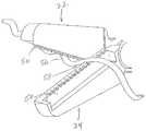
- FIG. 1is a side elevation view of an endoscopic instrument according to the invention.
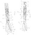
- FIG. 2is a longitudinal section of the endoscopic instrument of FIG. 1 taken along line 2 - 2 in FIG. 1 .
- FIG. 3is a partially transparent isometric view of the distal end of the endoscopic instrument of FIG. 1 .
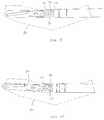
- FIG. 4is a broken partial section view of the distal end of the endoscopic instrument of FIG. 1 .
- FIG. 5is an isometric view of endoscopic scissors blades with a first embodiment of tissue stops coupled to the blades of the endoscopic instrument and showing the use of the tissue stops to retain a blood vessel.
- FIG. 6is an isometric view of endoscopic scissors blades with a second embodiment of tissue stops coupled to the blades of the endoscopic instrument.
- FIG. 7is an isometric view of endoscopic scissors blades with a third embodiment of tissue stops coupled to the blades of the endoscopic instrument.
- FIG. 8illustrates the use of the tissue stops of FIG. 7 to engage tissue.
- FIGS. 9 and 10are schematic illustrations of the operation of the cam-pin and cam-slot arrangement of the endoscopic instrument.
- FIG. 11is a broken section view of a central portion of the endoscopic instrument.
- the endoscopic instrument 10includes an elongate tubular member 12 preferably of a flexible construction having a proximal end 14 and a distal end 16 , a clevis 18 rotatably mounted at the distal end 16 of the tubular member 12 , and an end effector assembly 20 dimensioned for passage within the working channel of an endoscope.
- a control member 28is axially displaceable through and rotatable within the tubular member 12 .
- the distal end 30 of the control member 28is provided with a push rod 32 that is coupled to the end effector 20 to effect relative movement of the end effector in an opening and closing action, e.g., scissoring action, as the control member 28 is longitudinally translated within the tubular member 12 , as discussed in more detail below.
- a proximal handle assembly 34is coupled to the proximal end 14 of the tubular member 12 and the proximal end 36 of the control member 28 to effect relative longitudinal and rotational movement of the control member 28 and the tubular member 12 , as discussed further below.
- the end effector assembly 20is a scissors assembly including scissors blades 22 , 24 pivotally mounted on an axle 26 at the clevis 18 .
- the blades 22 , 24each include a medial surface 40 , a ground (or honed) surface 42 , which extends to, and ends in a sharp cutting edge 44 at an intersection with the medial surface, and a lateral surface 62 opposite the medial surface.
- the cutting edge 44extends from a location distal the pivot point to the distal end 46 of the blade.
- At least one blade, and more preferably both bladesincludes a friction enhancing tissue stop 50 that is laterally offset by an offset 45 from the cutting edge 44 (so as not to be present at the cutting edge at all).
- the offset 45is preferably less than 0.25 mm (0.012 inch) but may be a full blade-thickness offset from the cutting edge such that the tissue stop is mechanically attached to the lateral surface 62 .
- the tissue stop 50functions to hold and/or put traction on tissue without cutting the biological tissue, to hold or put traction on non-metallic articles such as sutures without cutting the same, and to not interfere with the cutting edge 44 of the blade.
- each tissue stop 50may be provided as an insert within a respective recess 52 that extends within the lateral side 62 of the respective blades 22 , 24 .
- Each tissue stop 50is retained in its recess 52 preferably by welding, bonding, brazing, riveting or another mechanical bonding or fit.
- the tissue stops 50may be manufactured from a different material than the material or materials defining the blades 22 , 24 .
- the tissue stops 50may be constructed of the same metal, a different metal, a carbon composite or a polymer composite.
- the tissue stopsmay be readily shaped by molding, casting, machining, photo-etching, forming or stamping.
- the tissue stops 50are each a rigid, sheet-form structure discrete from the scissors blades and attached thereto.
- the tissue stops 50are provided on both of the scissors blades 22 , 24 and include a continuous row of saw-like toothed projections 54 .
- the projectionsare not of sufficient height above the cutting edge 44 or sharpness to cut through tissue.
- the projectionsfunction to assist in holding slippery tissue, including blood vessels such as artery 56 in place even in the rear-most position of the open scissors blades 22 , 24 , e.g., at 58 , and prevent the common occurrence of such tissue from sliding forward and out from between the blades as the blades are moved into a closed position.
- the tissue stops 50may alternatively be received within a slot 60 in the ground surface 42 (with both the medial side 40 and lateral side 62 of the blade enclosing portions of the stop). The stop functions in the same manner as described above. As yet another alternative, the tissue stops 50 may be mounted external the blade on the lateral side 62 .
- Each tissue stop 150includes a first tenaculum (or grasping needle point) 152 provided adjacent, but proximally displaced relative to the distal end of its respective blade (e.g., blade 24 ), as well as a second tenaculum 154 at a position intermediate the proximal and distal ends of the blade.
- the distal tenaculum 152preferably extends a greater height from the ground surface 42 and is larger than the more proximal tenaculum 154 . As shown in FIG.
- the distal tenaculum 152is readily adapted to effectively pierce and maneuver tissue 154 , whereas the more proximal tenaculum 154 is configured to prevent tissue from sliding down the ground surface 42 toward the distal end 46 of the blade 24 .
- each blade 22 , 24includes a longitudinally extending cam-slot 70 (shown best with respect to blade 24 ) that is oriented at an oblique angle relative to the longitudinal axis A of the tubular member 12 .
- the cam-slot 70includes a bilaterally widened area 72 (on both sides of the axis of the cam-slot), preferably located at the proximalmost end 74 of the cam-slot.
- the push rod 32 joined to the distal end 30 of the control member 28includes and is provided with a transverse cam-pin 76 that rides in the cam-slot 70 of each of the blades 22 , 24 .
- the cam-pin 76is caused to ride within the cam-slots 70 causing the blades 22 , 24 to move in a scissoring action, with relative proximal movement of the control member causing the blades to move into a closed configuration, as shown in FIG. 9 . In the closed configuration shown in FIG.
- the end effector assembly 20is rotatable about the axis of the tubular member 12 by rotation of the control member 28 , as actuated from the proximal handle 30 .
- the clevisis mounted to the tubular member with a rotational bearing assembly 80 .
- an inner bearing 82is fixed to the distal end 16 of the tubular member either through bonding, welding or mechanical means such as crimping.
- the inner bearing 82includes distal bearing surfaces extending from the distal end of the tubular member.
- the bearing surfacesinclude a distal face 84 and a circumferential face 86 .
- the proximal face 88 of the clevis 18rotatably bears against the distal face 84 of the inner bearing 82 .
- An outer bearing 90is rotatably mounted on said circumferential face 86 of said inner bearing 82 and is secured about a proximal portion 92 of the clevis 18 , e.g., by crimping, to longitudinally secure the clevis in a smoothly rotatable manner to the inner bearing 82 and thus to the tubular member.
- Torque applied to the control member 28is thus transferred to the push rod 32 and cam pin 76 at the distal end thereof to directly rotate the end effectors 22 , 24 on 20 the clevis 18 about the distal end of the tubular member 16 .
- the torqueis applied directly to the end effectors 22 , 24 , rather than the clevis 18 (from which the control member 28 is de-coupled).
- the tubular member 12is preferably a flat or round wire wound coil 94 defining a flexible construct with a lubricious polymeric flexible outer jacket 96 .
- the control member 28is constructed to have different torsional and longitudinal stiffness along proximal and distal portions of its length.
- the control member 28is preferably constructed of discrete proximal and distal portions that are joined with a coupling element 98 , e.g., a short length of hypotube crimped to join such portions.
- the proximal portion 100is preferably a single spring steel stainless wire or a flexible composite carbon rod, but could also be made from a bi-radially wound wire cable (wound in opposing directions like “speedometer” cable).
- the distal portion 102has a length of 8 to 20 inches, and more preferably approximately 12 inches, and is a thin multi-strand cable of the above type or a drawn brazed strand (DBS) cable; i.e., a cable that has been drawn down in a die and brazed to bind the wires together to reduce the tendency of the cable to unwind if rotated against a load in the opposite direction of the winding.
- the distal portionis a single superelastic metal wire.
- the distal portionis capable of offering significant resilient flexibility, as well as accurate and directionally even application of torque—both clockwise and counterclockwise—without causing jump or whip (uneven or sudden rotation).
- the use of two discrete portionsoptimizes the control member in cost, function and repeatability.
- the instrumentremains relatively straight during use and the single steel wire or composite rod 100 is readily adapted to impart the longitudinal displacement and rotational torque from the proximal handle.
- the distal portion of the instrumentcan be subject to dramatic distortion as the instrument is bent through the tortuous path of a highly flexed (or even retroflexed) endoscope.
- a multistrand cable or superelastic wireis well-adapted to effect longitudinal displacement along such portion of the instrument as well as provide accurate and directionally even torque even while the distal end of the instrument is severely bent or retroflexed over.
- the distal end of the control member 28is provided with the push rod 32 , as discussed above, although other distal structure can be provided for attaching the control member to the end effectors.
- a polymeric tubular bearing 104is provided between the control member 28 and the wound wire coil 94 to take up the space between the two elements and prevent buckling of the control member 28 .
- the handle assembly 34included a shaft 110 having a distal end 111 , a proximal thumb ring 112 and a longitudinal slot 114 .
- a ferrule 118is rotatably mounted to a distal end 111 of the shaft 110 in communication with the longitudinal slot 114 .
- the proximal end of the tubular member 14is fixed within the ferrule 118 .
- a finger spool 120is longitudinally displaceable on the shaft 110 at the slot 114 .
- the proximal end 122 of the control memberis fixed with the spool 120 , e.g., with a set screw 124 .
Landscapes
- Health & Medical Sciences (AREA)
- Surgery (AREA)
- Life Sciences & Earth Sciences (AREA)
- Medical Informatics (AREA)
- Nuclear Medicine, Radiotherapy & Molecular Imaging (AREA)
- Engineering & Computer Science (AREA)
- Biomedical Technology (AREA)
- Heart & Thoracic Surgery (AREA)
- Molecular Biology (AREA)
- Animal Behavior & Ethology (AREA)
- General Health & Medical Sciences (AREA)
- Public Health (AREA)
- Veterinary Medicine (AREA)
- Pathology (AREA)
- Orthopedic Medicine & Surgery (AREA)
- Surgical Instruments (AREA)
Abstract
Description
Claims (17)
Priority Applications (11)
| Application Number | Priority Date | Filing Date | Title |
|---|---|---|---|
| US12/471,024US9277932B2 (en) | 2009-05-22 | 2009-05-22 | Endoscopic scissors instrument with friction enhancing tissue stops |
| CA2762172ACA2762172A1 (en) | 2009-05-22 | 2010-05-21 | Endoscopic instrument |
| CN2010800326218ACN102573672A (en) | 2009-05-22 | 2010-05-21 | Endoscopic instrument |
| EP10778444.9AEP2432406B1 (en) | 2009-05-22 | 2010-05-21 | Endoscopic instrument |
| BRPI1012156ABRPI1012156A2 (en) | 2009-05-22 | 2010-05-21 | endoscopic instrument. |
| CN201510003440.7ACN104840238B (en) | 2009-05-22 | 2010-05-21 | Endoscopic instrument |
| PCT/US2010/035714WO2010135615A1 (en) | 2009-05-22 | 2010-05-21 | Endoscopic instrument |
| JP2012512054AJP5671682B2 (en) | 2009-05-22 | 2010-05-21 | Endoscopic instrument |
| AU2010249437AAU2010249437B2 (en) | 2009-05-22 | 2010-05-21 | Endoscopic instrument |
| ES10778444TES2752055T3 (en) | 2009-05-22 | 2010-05-21 | Endoscopic instrument |
| US13/320,670US9566082B2 (en) | 2009-05-22 | 2010-05-21 | Endoscopic instrument |
Applications Claiming Priority (1)
| Application Number | Priority Date | Filing Date | Title |
|---|---|---|---|
| US12/471,024US9277932B2 (en) | 2009-05-22 | 2009-05-22 | Endoscopic scissors instrument with friction enhancing tissue stops |
Related Parent Applications (1)
| Application Number | Title | Priority Date | Filing Date |
|---|---|---|---|
| US12/471,057Continuation-In-PartUS20100298853A1 (en) | 2009-05-22 | 2009-05-22 | Endoscopic Instrument Having Rotatably Mounted End Effector Assembly |
Related Child Applications (1)
| Application Number | Title | Priority Date | Filing Date |
|---|---|---|---|
| US12/471,041Continuation-In-PartUS8690909B2 (en) | 2009-05-22 | 2009-05-22 | Endoscopic instrument with bi-laterally widened cam-slot at end effector |
Publications (2)
| Publication Number | Publication Date |
|---|---|
| US20100298852A1 US20100298852A1 (en) | 2010-11-25 |
| US9277932B2true US9277932B2 (en) | 2016-03-08 |
Family
ID=43125070
Family Applications (1)
| Application Number | Title | Priority Date | Filing Date |
|---|---|---|---|
| US12/471,024Active2031-06-13US9277932B2 (en) | 2009-05-22 | 2009-05-22 | Endoscopic scissors instrument with friction enhancing tissue stops |
Country Status (1)
| Country | Link |
|---|---|
| US (1) | US9277932B2 (en) |
Cited By (4)
| Publication number | Priority date | Publication date | Assignee | Title |
|---|---|---|---|---|
| US20160066947A1 (en)* | 2013-04-20 | 2016-03-10 | Apollo Endosurgery, Inc. | Flexible endoscopic torqueable devices |
| US10519677B2 (en)* | 2016-10-21 | 2019-12-31 | Olympus Corporation | Actuator and force driving mechanism for treatment tool |
| US20210282797A1 (en)* | 2020-03-10 | 2021-09-16 | Boston Scientific Limited | Medical device handle assemblies and methods of using the same |
| US20240225636A9 (en)* | 2022-05-19 | 2024-07-11 | Michael Domina | Scissor clamp |
Families Citing this family (10)
| Publication number | Priority date | Publication date | Assignee | Title |
|---|---|---|---|---|
| US9402644B2 (en)* | 2013-03-13 | 2016-08-02 | Covidien Lp | Reverse seam ripper dissector |
| JP1527839S (en)* | 2014-10-30 | 2015-06-29 | ||
| JP1527556S (en)* | 2014-10-30 | 2015-06-29 | ||
| US20190374242A1 (en)* | 2015-09-11 | 2019-12-12 | Katya Surgical Ltd | Multi-functional laparoscopic surgical apparatuses and applications thereof |
| CN109381254B (en)* | 2017-08-02 | 2024-02-13 | 上海市嘉定区安亭医院 | Needle holder with electrocoagulation function for digestive endoscopy |
| CN109381232B (en)* | 2017-08-02 | 2024-02-13 | 上海市嘉定区安亭医院 | Needle holding forceps for minimally invasive operation under digestive endoscope |
| CN109381243B (en)* | 2017-08-02 | 2024-02-13 | 上海市嘉定区安亭医院 | Vascular forceps with electrocoagulation function for digestive endoscopic surgery |
| CN109381237B (en)* | 2017-08-02 | 2024-02-13 | 上海市嘉定区安亭医院 | Vascular forceps for minimally invasive operation under digestive endoscope |
| EP3722219B1 (en) | 2019-04-12 | 2024-11-27 | Société Anonyme des Eaux Minérales d'Evian et en Abrégé "S.A.E.M.E" | Thin wall container made with a recycled material |
| DE102019134017A1 (en)* | 2019-12-11 | 2021-06-17 | Karl Storz Se & Co. Kg | Medical scissors for micro-invasive applications |
Citations (32)
| Publication number | Priority date | Publication date | Assignee | Title |
|---|---|---|---|---|
| US2012648A (en)* | 1933-06-10 | 1935-08-27 | Wheeler Howard Murwin | Florist's shears |
| US2052870A (en)* | 1936-02-18 | 1936-09-01 | Sara Coco | Clamping device |
| US2172490A (en) | 1938-06-17 | 1939-09-12 | Kenneth W Archibald | Rapid action ratchet torque applicator |
| US2490414A (en)* | 1946-09-27 | 1949-12-06 | United Tool & Die Company | Pinking scissors |
| US2814869A (en)* | 1955-11-02 | 1957-12-03 | Utica Drop Forge & Tool Corp | Cutting tool with workpiece retaining means |
| US3323208A (en)* | 1965-11-08 | 1967-06-06 | Jr James S Hurley | Simultaneous clamping and cutting means |
| US5203785A (en) | 1990-05-10 | 1993-04-20 | Symbrosis Corporation | Laparoscopic hook scissors |
| US5439478A (en) | 1990-05-10 | 1995-08-08 | Symbiosis Corporation | Steerable flexible microsurgical instrument with rotatable clevis |
| US5439471A (en)* | 1994-01-05 | 1995-08-08 | Kerr; Harry D. | Combined surgical needle holder and scissors |
| US5496347A (en) | 1993-03-30 | 1996-03-05 | Olympus Optical Co., Ltd. | Surgical instrument |
| US5499992A (en) | 1992-06-24 | 1996-03-19 | Microsurge, Inc. | Reuseable endoscopic surgical instrument |
| US5499997A (en) | 1992-04-10 | 1996-03-19 | Sharpe Endosurgical Corporation | Endoscopic tenaculum surgical instrument |
| US5700276A (en) | 1995-06-10 | 1997-12-23 | Olympus Winter & Ibe Gmbh | Surgical forceps |
| US5700270A (en) | 1995-10-20 | 1997-12-23 | United States Surgical Corporation | Surgical clip applier |
| US5758422A (en)* | 1996-11-13 | 1998-06-02 | Frank; Lisa Deborah | Scissors with interchangeable blades |
| US5893874A (en) | 1997-02-07 | 1999-04-13 | Smith & Nephew, Inc. | Surgical instrument |
| US5904702A (en) | 1997-08-14 | 1999-05-18 | University Of Massachusetts | Instrument for thoracic surgical procedures |
| US5984938A (en) | 1989-12-05 | 1999-11-16 | Yoon; Inbae | Surgical instrument with jaws and movable internal scissors and method for use thereof |
| US6015412A (en) | 1997-01-08 | 2000-01-18 | Atlantech Medical Devices Limited | Cutting device |
| US6027522A (en) | 1998-06-02 | 2000-02-22 | Boston Scientific Corporation | Surgical instrument with a rotatable distal end |
| US6059799A (en) | 1998-06-25 | 2000-05-09 | United States Surgical Corporation | Apparatus for applying surgical clips |
| US6159162A (en) | 1998-05-04 | 2000-12-12 | Lsvp International, Inc. | Biopsy apparatus |
| US6206877B1 (en) | 1997-08-27 | 2001-03-27 | Ethicon, Inc. | Combined bipolar scissor and grasper and method of forming thereof |
| US6409727B1 (en) | 1999-10-15 | 2002-06-25 | Scimed Life Systems, Inc. | Multifilar flexible rotary shaft and medical instruments incorporating the same |
| US20030036679A1 (en)* | 2001-08-16 | 2003-02-20 | Syntheon, Llc | Methods and apparatus for delivering a medical instrument over an endoscope while the endoscope is in a body lumen |
| US6554844B2 (en) | 1998-02-24 | 2003-04-29 | Endovia Medical, Inc. | Surgical instrument |
| US6634105B2 (en)* | 2000-06-03 | 2003-10-21 | Gardena Manufacturing Gmbh | Shears, particularly hand-held garden or pruning shears or secateurs |
| US6773434B2 (en) | 2001-09-18 | 2004-08-10 | Ethicon, Inc. | Combination bipolar forceps and scissors instrument |
| US20050101991A1 (en) | 2003-11-12 | 2005-05-12 | Applied Medical Resources Corporation | Overmolded grasper jaw |
| US20050192598A1 (en)* | 2004-02-27 | 2005-09-01 | Applied Medical Resources Corporation | System and method for actuating a laparoscopic surgical instrument |
| US20070244515A1 (en) | 2004-10-14 | 2007-10-18 | Fanous Medhat Y Z | Multipurpose Surgical Tool |
| US7572256B2 (en) | 1999-06-22 | 2009-08-11 | Senorx, Inc. | Shaped scalpel |
- 2009
- 2009-05-22USUS12/471,024patent/US9277932B2/enactiveActive
Patent Citations (32)
| Publication number | Priority date | Publication date | Assignee | Title |
|---|---|---|---|---|
| US2012648A (en)* | 1933-06-10 | 1935-08-27 | Wheeler Howard Murwin | Florist's shears |
| US2052870A (en)* | 1936-02-18 | 1936-09-01 | Sara Coco | Clamping device |
| US2172490A (en) | 1938-06-17 | 1939-09-12 | Kenneth W Archibald | Rapid action ratchet torque applicator |
| US2490414A (en)* | 1946-09-27 | 1949-12-06 | United Tool & Die Company | Pinking scissors |
| US2814869A (en)* | 1955-11-02 | 1957-12-03 | Utica Drop Forge & Tool Corp | Cutting tool with workpiece retaining means |
| US3323208A (en)* | 1965-11-08 | 1967-06-06 | Jr James S Hurley | Simultaneous clamping and cutting means |
| US5984938A (en) | 1989-12-05 | 1999-11-16 | Yoon; Inbae | Surgical instrument with jaws and movable internal scissors and method for use thereof |
| US5203785A (en) | 1990-05-10 | 1993-04-20 | Symbrosis Corporation | Laparoscopic hook scissors |
| US5439478A (en) | 1990-05-10 | 1995-08-08 | Symbiosis Corporation | Steerable flexible microsurgical instrument with rotatable clevis |
| US5499997A (en) | 1992-04-10 | 1996-03-19 | Sharpe Endosurgical Corporation | Endoscopic tenaculum surgical instrument |
| US5499992A (en) | 1992-06-24 | 1996-03-19 | Microsurge, Inc. | Reuseable endoscopic surgical instrument |
| US5496347A (en) | 1993-03-30 | 1996-03-05 | Olympus Optical Co., Ltd. | Surgical instrument |
| US5439471A (en)* | 1994-01-05 | 1995-08-08 | Kerr; Harry D. | Combined surgical needle holder and scissors |
| US5700276A (en) | 1995-06-10 | 1997-12-23 | Olympus Winter & Ibe Gmbh | Surgical forceps |
| US5700270A (en) | 1995-10-20 | 1997-12-23 | United States Surgical Corporation | Surgical clip applier |
| US5758422A (en)* | 1996-11-13 | 1998-06-02 | Frank; Lisa Deborah | Scissors with interchangeable blades |
| US6015412A (en) | 1997-01-08 | 2000-01-18 | Atlantech Medical Devices Limited | Cutting device |
| US5893874A (en) | 1997-02-07 | 1999-04-13 | Smith & Nephew, Inc. | Surgical instrument |
| US5904702A (en) | 1997-08-14 | 1999-05-18 | University Of Massachusetts | Instrument for thoracic surgical procedures |
| US6206877B1 (en) | 1997-08-27 | 2001-03-27 | Ethicon, Inc. | Combined bipolar scissor and grasper and method of forming thereof |
| US6554844B2 (en) | 1998-02-24 | 2003-04-29 | Endovia Medical, Inc. | Surgical instrument |
| US6159162A (en) | 1998-05-04 | 2000-12-12 | Lsvp International, Inc. | Biopsy apparatus |
| US6027522A (en) | 1998-06-02 | 2000-02-22 | Boston Scientific Corporation | Surgical instrument with a rotatable distal end |
| US6059799A (en) | 1998-06-25 | 2000-05-09 | United States Surgical Corporation | Apparatus for applying surgical clips |
| US7572256B2 (en) | 1999-06-22 | 2009-08-11 | Senorx, Inc. | Shaped scalpel |
| US6409727B1 (en) | 1999-10-15 | 2002-06-25 | Scimed Life Systems, Inc. | Multifilar flexible rotary shaft and medical instruments incorporating the same |
| US6634105B2 (en)* | 2000-06-03 | 2003-10-21 | Gardena Manufacturing Gmbh | Shears, particularly hand-held garden or pruning shears or secateurs |
| US20030036679A1 (en)* | 2001-08-16 | 2003-02-20 | Syntheon, Llc | Methods and apparatus for delivering a medical instrument over an endoscope while the endoscope is in a body lumen |
| US6773434B2 (en) | 2001-09-18 | 2004-08-10 | Ethicon, Inc. | Combination bipolar forceps and scissors instrument |
| US20050101991A1 (en) | 2003-11-12 | 2005-05-12 | Applied Medical Resources Corporation | Overmolded grasper jaw |
| US20050192598A1 (en)* | 2004-02-27 | 2005-09-01 | Applied Medical Resources Corporation | System and method for actuating a laparoscopic surgical instrument |
| US20070244515A1 (en) | 2004-10-14 | 2007-10-18 | Fanous Medhat Y Z | Multipurpose Surgical Tool |
Cited By (7)
| Publication number | Priority date | Publication date | Assignee | Title |
|---|---|---|---|---|
| US20160066947A1 (en)* | 2013-04-20 | 2016-03-10 | Apollo Endosurgery, Inc. | Flexible endoscopic torqueable devices |
| US10238411B2 (en)* | 2013-04-20 | 2019-03-26 | Apollo Endosurgery Us, Inc. | Flexible endoscopic torqueable devices |
| US10519677B2 (en)* | 2016-10-21 | 2019-12-31 | Olympus Corporation | Actuator and force driving mechanism for treatment tool |
| US20210282797A1 (en)* | 2020-03-10 | 2021-09-16 | Boston Scientific Limited | Medical device handle assemblies and methods of using the same |
| US12016585B2 (en)* | 2020-03-10 | 2024-06-25 | Boston Scientific Medical Device Limited | Medical device handle assemblies and methods of using the same |
| US20240225636A9 (en)* | 2022-05-19 | 2024-07-11 | Michael Domina | Scissor clamp |
| US12402904B2 (en)* | 2022-05-19 | 2025-09-02 | Michael Domina | Scissor clamp |
Also Published As
| Publication number | Publication date |
|---|---|
| US20100298852A1 (en) | 2010-11-25 |
Similar Documents
| Publication | Publication Date | Title |
|---|---|---|
| US9277932B2 (en) | Endoscopic scissors instrument with friction enhancing tissue stops | |
| US8690909B2 (en) | Endoscopic instrument with bi-laterally widened cam-slot at end effector | |
| US9566082B2 (en) | Endoscopic instrument | |
| AU2010249437B2 (en) | Endoscopic instrument | |
| US10188372B2 (en) | Surgical instrument guide device | |
| JP5523660B2 (en) | Medical instrument with articulatable end effector | |
| EP2376003B1 (en) | Endoscopic scissors instrument | |
| US12390090B2 (en) | Medical device with multiple degrees of freedom and related methods | |
| US20080300461A1 (en) | Endoscopic Device | |
| CA2513552A1 (en) | Re-shapeable medical device | |
| US20100298854A1 (en) | Endoscopic Instrument with Control Member Having Decreasing Torsional and Flexural Stiffness Along Its Length | |
| US20100298853A1 (en) | Endoscopic Instrument Having Rotatably Mounted End Effector Assembly | |
| US10492811B2 (en) | Rotatable endoscopic instrument | |
| US11612390B2 (en) | Suturing closure scope with alternative needle orientation | |
| US20130035718A1 (en) | Flexible forceps with improved torsional rigidity |
Legal Events
| Date | Code | Title | Description |
|---|---|---|---|
| AS | Assignment | Owner name:APOLLO ENDOSURGERY, INC., TEXAS Free format text:ASSIGNMENT OF ASSIGNORS INTEREST;ASSIGNOR:SLATER, CHARLES R.;REEL/FRAME:022900/0529 Effective date:20090626 | |
| AS | Assignment | Owner name:COMERICA BANK, A TEXAS BANKING ASSOCIATION, MICHIG Free format text:SECURITY AGREEMENT;ASSIGNOR:APOLLO ENDOSURGERY, INC.;REEL/FRAME:026530/0286 Effective date:20110622 | |
| AS | Assignment | Owner name:APOLLO ENDOSURGERY, INC., TEXAS Free format text:RELEASE BY SECURED PARTY;ASSIGNOR:COMERICA BANK;REEL/FRAME:030580/0085 Effective date:20130530 | |
| AS | Assignment | Owner name:SLATER, CHARLES R., FLORIDA Free format text:ASSIGNMENT OF ASSIGNORS INTEREST;ASSIGNOR:APOLLO ENDOSURGERY, INC.;REEL/FRAME:030635/0090 Effective date:20130530 | |
| AS | Assignment | Owner name:APOLLO ENDOSURGERY, INC., TEXAS Free format text:RELEASE BY SECURED PARTY;ASSIGNOR:COMERICA BANK;REEL/FRAME:031699/0959 Effective date:20131202 | |
| AS | Assignment | Owner name:SLATER ENDOSCOPY, LLC, FLORIDA Free format text:ASSIGNMENT OF ASSIGNORS INTEREST;ASSIGNOR:SLATER, CHARLES R.;REEL/FRAME:033187/0824 Effective date:20140624 | |
| AS | Assignment | Owner name:SLATR SURGICAL HOLDINGS LLC, FLORIDA Free format text:ASSIGNMENT OF ASSIGNORS INTEREST;ASSIGNOR:SLATER ENDOSCOPY, LLC;REEL/FRAME:034226/0926 Effective date:20141113 | |
| STCF | Information on status: patent grant | Free format text:PATENTED CASE | |
| FEPP | Fee payment procedure | Free format text:MAINTENANCE FEE REMINDER MAILED (ORIGINAL EVENT CODE: REM.); ENTITY STATUS OF PATENT OWNER: SMALL ENTITY | |
| FEPP | Fee payment procedure | Free format text:SURCHARGE FOR LATE PAYMENT, SMALL ENTITY (ORIGINAL EVENT CODE: M2554); ENTITY STATUS OF PATENT OWNER: SMALL ENTITY | |
| MAFP | Maintenance fee payment | Free format text:PAYMENT OF MAINTENANCE FEE, 4TH YR, SMALL ENTITY (ORIGINAL EVENT CODE: M2551); ENTITY STATUS OF PATENT OWNER: SMALL ENTITY Year of fee payment:4 | |
| AS | Assignment | Owner name:SLATER ENDOSCOPY, LLC, FLORIDA Free format text:ASSIGNMENT OF ASSIGNORS INTEREST;ASSIGNOR:SLATR SURGICAL HOLDINGS LLC;REEL/FRAME:058968/0767 Effective date:20220203 | |
| MAFP | Maintenance fee payment | Free format text:PAYMENT OF MAINTENANCE FEE, 8TH YR, SMALL ENTITY (ORIGINAL EVENT CODE: M2552); ENTITY STATUS OF PATENT OWNER: SMALL ENTITY Year of fee payment:8 |