US9274014B2 - Sensor assembly and method for measuring forces and torques - Google Patents
Sensor assembly and method for measuring forces and torquesDownload PDFInfo
- Publication number
- US9274014B2 US9274014B2US14/199,299US201414199299AUS9274014B2US 9274014 B2US9274014 B2US 9274014B2US 201414199299 AUS201414199299 AUS 201414199299AUS 9274014 B2US9274014 B2US 9274014B2
- Authority
- US
- United States
- Prior art keywords
- sensor assembly
- force
- light
- springs
- base plate
- Prior art date
- Legal status (The legal status is an assumption and is not a legal conclusion. Google has not performed a legal analysis and makes no representation as to the accuracy of the status listed.)
- Active, expires
Links
Images


Classifications
- G—PHYSICS
- G01—MEASURING; TESTING
- G01L—MEASURING FORCE, STRESS, TORQUE, WORK, MECHANICAL POWER, MECHANICAL EFFICIENCY, OR FLUID PRESSURE
- G01L5/00—Apparatus for, or methods of, measuring force, work, mechanical power, or torque, specially adapted for specific purposes
- G01L5/16—Apparatus for, or methods of, measuring force, work, mechanical power, or torque, specially adapted for specific purposes for measuring several components of force
- G—PHYSICS
- G01—MEASURING; TESTING
- G01L—MEASURING FORCE, STRESS, TORQUE, WORK, MECHANICAL POWER, MECHANICAL EFFICIENCY, OR FLUID PRESSURE
- G01L1/00—Measuring force or stress, in general
- G01L1/04—Measuring force or stress, in general by measuring elastic deformation of gauges, e.g. of springs
- G—PHYSICS
- G01—MEASURING; TESTING
- G01L—MEASURING FORCE, STRESS, TORQUE, WORK, MECHANICAL POWER, MECHANICAL EFFICIENCY, OR FLUID PRESSURE
- G01L3/00—Measuring torque, work, mechanical power, or mechanical efficiency, in general
- G01L3/02—Rotary-transmission dynamometers
- G01L3/04—Rotary-transmission dynamometers wherein the torque-transmitting element comprises a torsionally-flexible shaft
- G01L3/08—Rotary-transmission dynamometers wherein the torque-transmitting element comprises a torsionally-flexible shaft involving optical means for indicating
- G—PHYSICS
- G01—MEASURING; TESTING
- G01L—MEASURING FORCE, STRESS, TORQUE, WORK, MECHANICAL POWER, MECHANICAL EFFICIENCY, OR FLUID PRESSURE
- G01L3/00—Measuring torque, work, mechanical power, or mechanical efficiency, in general
- G01L3/02—Rotary-transmission dynamometers
- G01L3/14—Rotary-transmission dynamometers wherein the torque-transmitting element is other than a torsionally-flexible shaft
- G01L3/1407—Rotary-transmission dynamometers wherein the torque-transmitting element is other than a torsionally-flexible shaft involving springs
- G01L3/1421—Rotary-transmission dynamometers wherein the torque-transmitting element is other than a torsionally-flexible shaft involving springs using optical transducers
- G—PHYSICS
- G01—MEASURING; TESTING
- G01L—MEASURING FORCE, STRESS, TORQUE, WORK, MECHANICAL POWER, MECHANICAL EFFICIENCY, OR FLUID PRESSURE
- G01L5/00—Apparatus for, or methods of, measuring force, work, mechanical power, or torque, specially adapted for specific purposes
- G01L5/16—Apparatus for, or methods of, measuring force, work, mechanical power, or torque, specially adapted for specific purposes for measuring several components of force
- G01L5/166—Apparatus for, or methods of, measuring force, work, mechanical power, or torque, specially adapted for specific purposes for measuring several components of force using photoelectric means
- G—PHYSICS
- G01—MEASURING; TESTING
- G01L—MEASURING FORCE, STRESS, TORQUE, WORK, MECHANICAL POWER, MECHANICAL EFFICIENCY, OR FLUID PRESSURE
- G01L5/00—Apparatus for, or methods of, measuring force, work, mechanical power, or torque, specially adapted for specific purposes
- G01L5/22—Apparatus for, or methods of, measuring force, work, mechanical power, or torque, specially adapted for specific purposes for measuring the force applied to control members, e.g. control members of vehicles, triggers
- G01L5/226—Apparatus for, or methods of, measuring force, work, mechanical power, or torque, specially adapted for specific purposes for measuring the force applied to control members, e.g. control members of vehicles, triggers to manipulators, e.g. the force due to gripping
Definitions
- the disclosurerelates generally to a force/torque sensor assembly and a method for measuring forces and torques.
- the force/torque sensor assembly and methodare employed in a robotic system comprising an instrument and a manipulator used to position the instrument.
- robotic systemstypically include a manipulator having a moveable arm comprising one or more links.
- a surgical instrumentis attached to a free end of the arm.
- the instrumentis designed to be applied to a surgical site.
- a controllerregulates movement of the arm to position the instrument with a high degree of accuracy at the surgical site.
- a component of many robotic systemsis a force/torque sensor assembly.
- the force/torque sensor assemblyis attached between the free end of the arm and the instrument.
- the force/torque sensor assemblymonitors forces and torques that are applied to the instrument. These may be forces and torques that are applied to the instrument as a consequence of the instrument pressing against tissue. These also may be forces and torques a practitioner applies in order to set a position and/or orientation of the instrument.
- Signals output by the force/torque sensor assemblyare received by the controller.
- the controlleruses these signals to determine a target position for the instrument. Based on the determined target position, the controller actuates the arm in order to advance the arm so that the instrument is moved to the target position.
- One type of six component force/torque sensor assemblycomprises a set of strain gauges. These gauges include a static member to which a plurality of beams are flexibly mounted. Typically one or more strain gauges are associated with each beam. Each strain gauge acts as a transducer that is used to convert a force or torque into an electrical signal. Each strain gauge generates an electrical signal proportional to the flexure of the beam with which the strain gauge is associated. The output signals from the strain gauges are input variables into an algorithm that yields the measured forces and torques.
- thermal driftis a common problem. Thermal drift occurs when a change in temperature causes a contraction or expansion of parts. Thermal drift can result in inaccurate placement of the instrument at the surgical site. It is also common for these types of force/torque sensor assemblies to take force and torque measurements at a single resolution. In some cases it may be desirable for the force/torque sensor assembly to be capable of measuring forces and torques at multiple resolutions.
- a sensor assemblycomprising a base plate and a sensor member displaceable relative to the base plate.
- a spring arrangementoperates in first and second stages in response to displacement of the sensor member relative to the base plate. Different resolutions of force and torque measurements are associated with the first and second stages.
- a light sensitive transducersenses displacement of the sensor member relative to the base plate and generates corresponding output signals.
- a sensor assemblycomprising a light sensitive transducer having a plurality of pixels.
- a light sourceprovides light to be directed in a plurality of light beams onto the light sensitive transducer so that the light beams strike different pixels of the light sensitive transducer to sense displacement of a sensor member relative to a base plate.
- a methodfor assessing forces and torques using a sensor including a light sensitive transducer having a plurality of pixels.
- the methodcomprises operating the sensor to direct a plurality of light beams onto the light sensitive transducer.
- a loadis applied on the sensor so that each of the plurality of light beams move on the light sensitive transducer. Forces and torques are determined based on differences in locations of pixels lighted by the light beams as the light beams move in response to the applied load.
- Robotic systems and methods employing these sensor assemblies and methods for assessing forces and torquesare also provided.
- the sensor assembliesare capable of determining forces and torques at different resolutions for certain applications.
- Another advantageis that the sensor assemblies operate optically to avoid potential thermal drift issues associated with strain gauges.
- FIG. 1is an overview of a robotic system including a manipulator used to position and advance a surgical instrument on a patient;
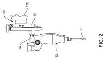
- FIG. 2is a side view of a force/torque sensor assembly to which the surgical instrument, an instrument mount, and a mounting plate are attached;
- FIG. 3is a side view of the force/torque sensor assembly seated between an arm of the manipulator and mounting plate, the force/torque sensor assembly including a head plate, a diverter plate with an inner and outer hub, and a base plate;
- FIG. 4is an exploded perspective view of the force/torque sensor assembly
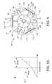
- FIG. 5is a plan view of a diverter plate of the force/torque sensor assembly
- FIG. 5Ais a graph showing two stages of sensitivity of the force/torque sensor assembly
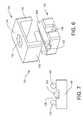
- FIG. 6is an exploded perspective view of pins in a pin housing
- FIG. 7is a side view illustrating the pins in the pin housing
- FIG. 8is a plan view of the diverter plate with the pins located in serpentine springs of the diverter plate;
- FIG. 9is a partial cross-sectional view through the pins in the serpentine spring.
- FIG. 10is a plan view of the base plate
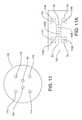
- FIG. 11is a plan view of a collimator of the force/torque sensor assembly
- FIG. 11Ais a plan view of a light sensitive transducer illustrating separate sectors associated with separate light beams
- FIG. 12Ais a cross-sectional view illustrating the collimator with a plurality of normal bores extending through the collimator
- FIG. 12Bis a cross-sectional view illustrating the collimator with the plurality of normal bores in a different orientation than FIG. 12A ;
- FIG. 13Ais a cross-sectional view illustrating the collimator with a plurality of angled bores extending through the collimator;
- FIG. 13Bis a cross-sectional view illustrating the collimator with the plurality of angled bores in a different orientation than FIG. 13A ;
- FIG. 14Ais a plan view of the light sensitive transducer of the force/torque sensor assembly illustrating where light beams strike the light sensitive transducer at a start of a time frame;
- FIG. 14Bis a plan view of the light sensitive transducer illustrating where light beams strike the light sensitive transducer at an end of the time frame;
- FIG. 15is a plan view of the light sensitive transducer showing locations of centroids of lights beams
- FIGS. 15A and 15Bare graphs illustrating changes in signal intensity along pixel columns and rows, respectively, used to determine the centroids of the light beams illustrated in FIG. 15 ;
- FIG. 16is an illustration of the correlation between movement of light beams on the light sensitive transducer with three torques T x , T y and T z , and three forces F x , F y and F z ;
- FIG. 17is a schematic view of the instrument, bur, and force/torque sensor assembly showing a distance R from a centroid of the bur to a center of the force/torque sensor assembly;
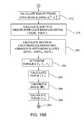
- FIGS. 18A-18Care flow diagrams illustrating steps carried out by methods of sensing forces and torques
- FIG. 19is a schematic illustration of the collimator and changes in where one light beam strikes the light sensitive transducer between the start of the time frame and the end of the time frame;
- FIG. 20is a plan view of an alternative collimator
- FIG. 21is a perspective view of the alternative collimator of FIG. 20 ;
- FIG. 22is a plan view of an alternative embodiment of the diverter plate in which pins are vertically seated within serpentine springs;
- FIG. 23is a plan view of a second alternative embodiment of the diverter plate.
- FIG. 24is a plan view of a third alternative embodiment of the diverter plate.
- FIG. 1illustrates a robotic surgical system including a manipulator 30 and a surgical instrument 32 .
- the surgical instrument 32is supported by the manipulator 30 for movement with respect to a patient P.
- the manipulator 30functions in manual and semi-autonomous modes to position the instrument 32 with respect to a target site on the patient P.
- the manipulator 30includes an instrument mount 36 to which the instrument 32 is rigidly attached. In some embodiments, the instrument 32 is also removably attached to the instrument mount 36 . Manipulator 30 moves the instrument mount 36 to position and orient the instrument 32 so that the instrument 32 performs the intended medical/surgical procedure on the patient P.
- a surgical navigation system 220monitors the position and/or orientation of the instrument 32 relative to the target site.
- the surgical navigation system 220communicates position and/or orientation data to the manipulator 30 so that the manipulator 30 can properly position the instrument 32 .
- Manipulator 30includes a mobile cart 38 .
- a linkage assembly 40moveably connects the instrument 32 to the cart 38 .
- this linkage assembly 40comprises first and second parallel four bar link assemblies 42 , 44 .
- the position of each joint of each link assemblyis set by a plurality of actuators 46 .
- one of the actuators 46 associated with link assembly 42is identified.
- a manipulator controller 48(partially shown as a phantom box in FIG. 1 ) is mounted to the cart 38 .
- the manipulator controller 48transmits the control signals that cause the actuators 46 to appropriately set the links of the link assemblies 42 , 44 .
- the manipulator controller 48sets the positions of the links based on a number of input signals. These input signals include signals from the surgical navigation system 220 .
- the instrument 32includes a power generating unit (not shown).
- the power generating unitconverts electrical signals into a form of energy that is applied to the patient P. This energy may be mechanical, sonic, thermal, RF, EM or photonic.
- the instrument 32includes a power generating unit, the energy is applied to the target site through an energy applicator 50 .
- the instrument 32includes an energy applicator 50 in the form of a cutting bur for cutting tissue such as bone. The bur extends from a handpiece of the instrument 32 .
- a force/torque sensor assembly 52is provided to react to loads applied to the instrument 32 .
- the loadsmay include resistive forces and torques to which the instrument 32 is exposed as a result of the instrument 32 being pressed against tissue.
- the loadsmay also include forces and torques applied to the instrument 32 by a user when the user desires to set a position and/or orientation of the instrument 32 .
- Manipulator controller 48sets the position of the links, and thus the instrument 32 , based on the forces and torques measured by the force/torque sensor assembly 52 .
- the force/torque sensor assembly 52acts between the linkage assembly 40 and the instrument 32 .
- the force/torque sensor assemblyincludes a head plate 54 , a diverter plate 56 and a base plate 58 . These plates 54 , 56 , 58 support the force/torque sensor assembly 52 for operation between the linkage assembly 40 and the instrument 32 .
- the widths of the plates 54 , 56 and 58are exaggerated for purposes of illustration.
- the head plate 54is disc shaped so as to have opposed proximally and distally directed faces that are planar and parallel to each other.
- Head plate 54is formed from a single piece of stainless steel or other metal alloy.
- Head plate 54has a thickness of approximately 6.5 mm. In some embodiments, head plate 54 has a diameter of between about 4.5 and 6.5 mm.
- Head plate 54is attached to a proximally directed face of a mounting plate 60 .
- the mounting plate 60is fixed to the instrument mount 36 .
- proximalis understood to be towards the manipulator cart 38 , away from the target site to which the instrument 32 is to be applied and “distal” is understood to be away from manipulator cart 38 , towards the target site to which the instrument 32 is to be applied).
- first and second throughbores 62 , 64extend between the opposed faces of the head plate 54 .
- the first throughbores 62are located radially outward from the center of the head plate 54 .
- the first throughbores 62are equally spaced from each other.
- a proximal opening of first throughbores 62is defined by a tapered recess 66 that is angled inwardly toward the center of first throughbores 62 .
- Second throughbores 64are spaced radially outwardly from first throughbores 62 so as to be located a small distance inwardly from an outer perimeter of head plate 54 .
- the second throughbores 64are also equally spaced from each other, yet not radially aligned with the adjacent first throughbore 62 .
- Head plate 54is further formed to define a side bore 68 that extends radially inwardly from a side surface of the head plate 54 .
- Threaded fastenersextend through second throughbores 64 to hold the head plate 54 to the mounting plate 60 .
- Diverter plate 56is located between the head plate 54 and the base plate 58 .
- Diverter plate 56includes inner and outer sensor members.
- the inner and outer sensor membersare inner and outer hubs, 70 and 72 , respectively.
- Inner hub 70extends distally forward of the outer hub 72 .
- Inner hub 70is connected to and able to move relative to the outer hub 72 .
- Outer hub 72is statically secured to base plate 58 .
- the inner hub 70is statically secured to head plate 54 .
- the hubs 70 , 72are both formed out of a single piece of hardened stainless steel.
- Inner hub 70has a generally circular outer shape. Inner hub 70 is disposed within the outer hub 72 . An outer perimeter of the inner hub 70 is defined, in part, by three flat surfaces 74 that are arcuately and equally spaced from each other. A curved surface 76 is located between each adjacent pair of flat surfaces 74 .
- Tines 78extend radially outwardly from each curved surface 76 . Tines 78 are equiangularly spaced apart from each other and extend from the centers of curved surfaces 76 . Along the axes that extend between the opposed proximally and distally directed faces of the tines 78 , the tines 78 have a depth that is from about 0.25 mm to about 1.0 mm less than the depth of inner hub 70 . The proximal faces (not numbered) of the tines 78 are flush with the proximal face of the inner hub 70 . The distally directed faces (not numbered) of the tines are thus recessed relative to the adjacent distally directed face of inner hub 70 .
- Hub throughbores 80are located a short distance inward from the outer perimeter of inner hub 70 .
- Hub throughbores 80have openings with a diameter approximately equal to the diameter of first throughbores 62 in head plate 54 .
- Each hub throughbore 80aligns with a separate first throughbore 62 .
- Inner hub 70has a centrally located central throughbore 82 .
- Central throughbore 82is larger in diameter than hub throughbores 80 .
- a cylindrical step 84projects radially from an inner surface that defines the central throughbore 82 .
- Step 84is recessed proximally away from the distal face of the inner hub 70 .
- Step 84extends inwardly approximately 0.75 mm from the inner surface of central throughbore 82 .
- a groove 86extends radially outwardly from central throughbore 82 . Groove 86 is recessed relative to the distal face of inner hub 70 .
- the base of groove 86is coplanar with step 84
- outer hub 72is generally ring-like in shape. Outer hub 72 has a diameter approximately equal to that of head plate 54 . The outer hub 72 has the same proximal face-to-distal face depth as the tines 78 . Thus the depth of the outer hub 72 is less than that of inner hub 70 . The distal face of inner hub 70 is raised above the distal face of outer hub 72 , as seen in FIG. 3 . In FIG. 3 , the extent to which the inner hub 70 projects forward from the outer hub 72 is exaggerated for purposes of illustration.
- Outer hub 72has three inwardly directed tabs 88 .
- Tabs 88are equiangularly spaced apart from each other.
- Each tab 88has side surfaces 90 that taper inwardly towards each other.
- Each tab 88has an arcuately shaped inner surface 92 .
- Inner surfaces 92extend around a common circle that is concentric with the center axis of outer hub 72 .
- Each tab 88is bisected by a tine slot 94 .
- Each tine slot 94extends radially outwardly from the inner surface 92 .
- Each tab 88also has a tab throughbore 96 .
- Tab throughbores 96are spaced circumferentially apart along the outer hub 72 .
- Outer hub 72is further shaped so that there is planar inner surface, a flat 98 , between each adjacent pair of tabs 88 .
- Tine slots 94have a width that is approximately 0.1 mm to 0.75 mm greater than the width of tines 78 .
- Diverter plate 56is further dimensioned so that when the outer hub 72 is in the neutral position, the outer end of each tine 78 is spaced approximately 0.1 mm to 0.75 mm from the adjacent inwardly directed surfaces of the tab 88 that defines the associated tine slot 94 .
- a spring arrangementmovably attaches the inner hub 70 to the outer hub 72 .
- the spring arrangementincludes three spring devices 102 .
- Each spring device 102extends outwardly from a separate one of the flat surfaces 74 .
- Each spring device 102includes a serpentine spring 104 and a leaf spring 106 arranged in series.
- Each serpentine spring 104includes a head 108 , a torso 110 and a leg 112 .
- the head 108is the portion of the serpentine spring 104 connected to the inner hub 70 .
- the head 108projects radially outwardly from the flat surface 74 .
- the torso 110extends from the head 108 .
- Each torsoincludes a plurality of U-shaped folds 114 and pleats 116 extending from the U-shaped folds 114 .
- the torso 110is formed from plural pleats 116 and folds 114 .
- the pleats 116are parallel to each other.
- Folds 114are generally semi-circular in shape. A first one of the folds 114 connects one pleat 116 to the head 108 . A second one of the folds 114 connects two pleats 116 together. A third one of the folds 114 connects another pleat 116 to the leg 112 .
- Folds 114are flexible. The flexibility of the folds 114 allows the longitudinal axes of the pleats 116 to shift positions.
- Each leg 112comprises a relatively thick base. This base of the leg 112 is the portion of the leg 112 from which the adjacent fold 114 extends.
- Two feet 118extend outwardly from the outer end of each leg 112 .
- Each foot 118is in the form of a thin strip having a thickness of approximately 0.25 to 0.75 mm.
- the feet 118 forming a pair of feet 118are coplanar.
- Each foot 118has an end that merges into the side surface of an adjacent tab 88 .
- the feet 118merge into the tabs 88 at locations inwardly radially from the flats 98 .
- each pair of feet 118is parallel with and spaced inwardly from the adjacent flat 98 .
- this spacingis between approximately 0.25 mm and 0.75 mm. Given that feet 118 are formed from flexible material and the feet 118 of each pair of feet 118 are coplanar, each pair of feet 118 defines one of the leaf springs 106 .
- Each spring device 102can thus be considered to be a plural stage spring device.
- One spring stageis the serpentine spring 104 formed by folds 114 and pleats 116 .
- the second spring stageis the leaf spring 106 formed by feet 118 .
- FIG. 5Aillustrates how these first and second stages affect the resolution of force/torque measurements enabled by the force/torque sensor assembly 52 .
- each serpentine spring 104accommodates a plurality of pins 120 .
- Each pin 120is generally cylindrical in shape.
- Each pin 120is comprised of hardened stainless steel.
- Each pin 120has a length such that the pin 120 can extend across the entire width of the adjacent torso 110 .
- the pins 120have a radius that is approximately 0.625 mm to 2.5 mm less than the radius of circles defined by the adjacent folds 114 . In one embodiment, pins 120 are approximately 6.25 mm in length and 1.168 mm in diameter.
- a first one of the pins 120extends between the head 108 and the adjacent pleat 116 .
- a second of the pins 120is located between the two pleats 116 .
- a third of the pins 120is located between the radially outermost pleat 116 and the leg 112 .
- Pin housing 122is comprised of a cap 124 and a pin housing base 126 .
- Pins 120are positioned between the cap 124 and the pin housing base 126 .
- Cap 124includes a panel 128 , and two opposed side walls 130 .
- Panel 128is rectangular in shape. Each side wall 130 extends downward from side edges of panel 128 .
- a panel bore 132extends through the center of panel 128 .
- Pin housing base 126is generally block-like in shape.
- a base groove 134extends through the middle of pin housing base 126 .
- Base groove 134is dimensioned to accept torso 110 .
- a pin groove 136extends through the center of pin housing base 126 .
- Pin groove 136intersects and is perpendicular to the base groove 134 .
- the pin groove 136is of shallower depth than the base groove 134 .
- base plate 58is attached to a distal end component 138 of the linkage assembly 40 of the manipulator 30 .
- This component 138may be a coupler, robot flange, wrist or other component.
- the base plate 58is formed from hardened stainless steel.
- Base plate 58is generally disc like in shape and has an outer diameter equal to that of the outer diameter of outer hub 72 .
- the base plate 58has an inner circular section 140 and an outer rim 142 .
- Rim 142extends circumferentially around the outer edge of circular section 140 .
- Rim 142has a distally directed top face that is raised above and parallel with the distally directed face of inner circular section 140 .
- Rim 142is formed to have a plurality of first openings 144 and second openings 146 that extend between the opposed proximally and distally directed faces of the rim 142 . There are three first openings 144 that are equiangularly spaced apart from each other. There are three second openings 146 that are equiangularly spaced apart from each other.
- a plurality of recesses 148are located on the distal face of rim 142 .
- the recesses 148are open along the inner surface of rim 142 .
- Each recess 148is generally in the form of a rectangle.
- Each recess 148is defined by a pair of opposed side surfaces and a bottom surface.
- Each recess 148is shaped so the distance across the opposed side surfaces are equal to the width across tine slots 94 .
- Three recesses 148are equally spaced apart on the distal face of rim 142 .
- the recesses 148are positioned so that when force/torque sensor assembly 52 is assembled, each recess 148 is in registration with one of the tine slots 94 in the diverter plate 56 .
- Fastenersextend through the first openings 144 to hold the base plate 58 to the distal end component 138 of the linkage assembly 40 .
- Fastenersextend through the second openings 146 and tab throughbores 96 to hold the diverter plate 56 to the base plate 58 .
- the force/torque sensor assembly 52is an optically-based sensor assembly that includes a light source 154 mounted to the base plate 58 . Light from the light source 154 is directed through a collimator 156 onto a light sensitive transducer 158 . The collimator 156 converts the light into a plurality of light beams. As loads are applied on the instrument 32 , the collimator 156 is displaced relative to the light sensitive transducer 158 so that the light beams strike different pixels of the light sensitive transducer 158 . This movement of the light beams effectively senses the forces and torques applied to the instrument 32 and can be correlated into force and torque measurements.
- the light source 142is located adjacent to the outer edge of the distal face of inner circular section 140 . Light source 142 is thus adjacent and may be coplanar with the inwardly directed face of rim 142 .
- light source 142is an LED light source that includes one or more light emitting diodes (LEDs). Two LEDs are shown in FIG. 4 .
- a light pipe 160is mounted to a distal face of inner hub 70 .
- the light pipe 160receives light emitted by the light source 142 and directs it to the collimator 156 .
- Light pipe 160is shaped to have a cylindrical stem 162 .
- the proximal end of the stem 162is located above light source 142 to receive light emitted from the light source 142 .
- a branch 164extends perpendicularly from a distal end of stem 162 .
- Branch 164is dimensioned to seat in inner hub groove 86 .
- a circular head 166extends from a free end of the branch 164 .
- Head 166is formed to have a disc shaped lens. Head 166 is dimensioned to seat in a counterbore to central throughbore 82 .
- the light pipe 160is formed of plastic, glass or other material that is able to convey light emitted by light source 142 to the collimator 156 .
- the light pipe 160is a fiber optic conduit or an injection molded light pipe comprised of a single piece of plastic.
- the light pipe 160is eliminated altogether and the LEDs are instead positioned directly above the collimator 156 or other light focusing device.
- Collimator 156is fixed to the inner hub 70 .
- the collimator 156may be fixed by adhesive, tape, welding or other methods.
- Collimator 156is seated in the counterbore beneath the light pipe 160 .
- Collimator 156is disc shaped and has a diameter approximately equal to counterbore so that the outer perimeter of collimator 156 seats on step 84 formed in inner hub 70 .
- collimator 156has a diameter of approximately 7.5 mm.
- the collimator 156is formed from quartz or alternatively is built into the diverter plate 56 (e.g., machined to be a part of the diverter plate 56 ).
- collimator 156is formed to have a plurality of light openings. Four of the light openings are shown as normal bores 172 , 174 , 176 , 178 .
- Normal bores 172 , 174 , 176 , 178are throughbores formed normally to opposed top and bottom surfaces of the collimator 156 , i.e., normal bores 172 , 174 , 176 , 178 extend through collimator 156 along axes perpendicular to the opposed top and bottom surfaces of the collimator 156 .
- the normal bores 172 , 174 , 176 , 178are arranged in a square pattern and spaced equidistantly from a center of collimator 156 .
- the plurality of light openingsalso include two angled bores 180 , 182 , as seen in FIGS. 11 , 13 A and 13 B.
- Angled bores 180 , 182are angled in that they extend through the collimator 156 along axes that are arranged at an acute angle to the normal axes between the top and bottom surfaces of the collimator 156 .
- Angled bores 180 , 182are spaced equally away from the center of the collimator 156 .
- Angled bores 180 , 182angle inwardly towards the center of collimator 156 .
- bores 172 , 174 , 176 , 178 , 180 , 182are square-shaped. In other embodiments, bores 172 , 174 , 176 , 178 , 180 , 182 are circular in shape.
- the light sensitive transducer 158is located centrally on a printed circuit board 184 .
- the printed circuit board 184is seated on the distally directed face of circular section 140 and is thereby fixed with respect to the base plate 58 .
- the printed circuit board 184has a shape and size approximately equal to that of the distal face of circular section 140 .
- the light sensitive transducer 158is an image sensor.
- the image sensormay be a CMOS image sensor or any other light sensitive transducer.
- the image sensoris the LUPA 1300A sensor available from Cypress Semiconductor of San Jose, Calif.
- the light sensitive transducer 158contains a number of individual light sensitive elements such as pixels.
- the pixelsare arranged in a row-by-column format or matrix. Each pixel outputs a signal representative of the strength of the light striking the pixel.
- light sensitive transducer 158has a pixel size of 25 microns or less.
- the light sensitive transducer 158has a resolution of 1280 ⁇ 1024 pixels. Each pixel is approximately 14 microns by 14 microns in this embodiment.
- a voltage regulator 186is mounted to printed circuit board 184 .
- Voltage regulator 186supplies a constant voltage signal to light sensitive transducer 158 .
- light sensitive transducer 158is shown mounted to an exposed face of voltage regulator 186 .
- the bores 172 , 174 , 176 , 178 , 180 , 182 of the collimator 156divide the light from the light pipe 160 into a number of separate light beams.
- the light beamsstrike a face of the light sensitive transducer 158 .
- Light sensitive transducer 158outputs signals representative of the locations that the light beams strike on the light sensitive transducer 158 . These signals may be sent to a local controller (not shown) for processing. The signals are processed to ultimately yield forces and torques.
- the manipulator controller 48utilizes the forces and torques to control movement of the actuators 46 and, thus, the instrument 32 . It should be appreciated that the output signals from the light sensitive transducer 158 could also be sent directly to the manipulator controller 48 in other embodiments.
- Force/torque sensor assembly 52is considered to be in a loaded state when loads are applied to the instrument 32 .
- loadse.g., forces and/or torques
- the inner hub 70can engage in six types of movement relative to the outer hub 72 . Three of the movements are translation.
- the inner hub 70can move along the x-axis, arbitrarily, the horizontal axis through the inner hub 70 in FIG. 5 .
- Inner hub 70can engage in movement along the y-axis, arbitrarily the vertical axis through the inner hub 70 in FIG. 5 .
- the inner hubcan engage in movement along the z-axis, arbitrarily the axis through the center of the inner hub 70 that extends in and out of the plane of FIG.
- Inner hub 70can also engage in at least some rotational movement around each of the above-identified axes. Typically as a result of the application of forces and torques to the force/torque sensor assembly 52 , the inner hub 70 engages in several of these movements.
- the collimator 156 and light pipe 160When there is an application of force and/or torque to the instrument 32 , the collimator 156 and light pipe 160 , consequently, equally move with the inner hub 70 . This displacement of the collimator 156 causes light emitted by the light source 154 to strike different pixels of the light sensitive transducer 158 .
- the light sensitive transducer 158outputs signals that show the movements of the collimated light which is directly related to the forces and torques applied to the instrument 32 .
- the force/torque sensor assembly 52In the absence of the application of any forces or torques to the force/torque sensor assembly 52 , the force/torque sensor assembly 52 is considered in the unloaded state.
- gravityimposes forces and torques on the force/torque sensor assembly 52 .
- a major component of this gravitation forceis the force gravity places on the instrument 32 and energy applicator 50 .
- This gravitational forcecauses some displacement of the inner hub 70 relative to the outer hub 72 when inner hub 70 is in the pure unloaded state. Given the nominal nature of this force, and nominal displacement of the inner hub 70 , the locations of the light beams are considered to be in their gravity-offset unloaded state.
- the light emitted by the light source 154extends through bores 172 , 174 , 176 , 178 , 180 , 182 as light beams.
- These light beamsstrike different clusters of pixels on the surface of the light sensitive transducer 158 . More specifically, each light beam strikes a different cluster of pixels in the unloaded state and in the loaded state.
- the shifts in the positions/locations of the clusters of pixels from the unloaded state to the loaded statee.g., from a start of a time frame (initial cluster) to an end of the time frame (final cluster), are used to determine the forces and torques.
- FIGS. 12A and 12Bdepict two of the light beams that pass through two of the normal bores, bores 172 and 176 in the unloaded and loaded states.
- FIGS. 13A and 13Bdepict how two light beams pass through the angled bores 180 , 182 in the unloaded and loaded states.
- the light beams that pass through the angled bores 180 , 182strike the light sensitive transducer 158 as ellipses.
- the collimator 156is arranged with respect to the light sensitive transducer 158 so that for the maximum range of motion of each light beam (for all six degrees of freedom) each light beam is constrained to separate sectors S (or windows) on the light sensitive transducer 158 , so that the pixels in each sector S can be separately electronically processed to determine a location of a centroid of the light beam on the light sensitive transducer 158 . See, for example, the light beams 172 B, 174 B, 176 B, 178 B shown in FIG.
- each of the light beamsare constrained to remain fully in their corresponding sectors S 1 -S 6 .
- the light sensitive transducer 158continually outputs to manipulator controller 48 the signals emitted by each pixel in each sector S 1 -S 6 .
- Each pixelhas a specific row/column location on the light sensitive transducer 158 .
- the signals received by manipulator controller 48are proportional to the quantity of light that strikes the pixel at that location.
- the pixel at the lower left of FIGS. 14A and 14Bis considered to be the pixel at row/column location (0, 0) 188 .
- each light beamstrikes a cluster of pixels in each sector S 1 -S 6 .
- the controller 48receives from the light sensitive transducer 145 signals that make up an image that includes six sets of pixels, each set comprising output signals from multiple pixels that are exposed to light. For each of these sets of pixels, the controller 48 determines the centroid of the light beams.
- the centroidscan be determined by processing the signal strengths in each set using conventional processing techniques, as shown in FIGS. 15 , 15 A, and 15 B.
- the light beams 172 B, 174 B, 176 B, 178 B shown in FIG. 15which pass through the normal bores 172 , 174 , 176 , 178 , strike distinct clusters of pixels.
- These clustersare processed by summing the signal strengths, for each set of pixels associated with sectors S 1 -S 4 , along all the columns of pixels, and all the rows of pixels, in each sector and identifying the peak signal strengths along the columns and rows to identify the centroid in x, y coordinates.
- the peak signal strengthsmay be associated with a specific pixel location, but interpolation or other processing of the summed output signal values may result in the location of the peak signal strengths along the columns and rows not necessarily being bound by physical location of a single pixel. See an example of this processing in FIGS. 15A and 15B .
- Controller 48assigns the location of the centroid in the x-y coordinate system of the light sensitive transducer 158 to be on the on-sensor location to which the light beam is applied. Controller 48 performs the above processes six times, once for each light beam and sector. This process is repeated in each frame of operation of the force/torque sensor assembly 52 . Therefore, for each frame of operation, twelve x, y coordinates are provided in the embodiment in which the collimator 156 has four normal bores 172 , 174 , 176 , 178 and two angled bores 180 , 182 .
- the minimum frequency with which a complete set of signals for all the pixels is outputis 1 Hz. In some embodiments, the frequency in which a complete set of signals for all pixels is output is at least 10 Hz or greater.
- Each set of signalscan be considered to represent the positions of the light beams at the end of a single time frame.
- each of the light beamsshift equally along the x-axis, and therefore, F x can be correlated to a shift in one of the x coordinates of the light beams, such as by a shift in x1, x3, and/or x4.
- F ycan be correlated to a shift in one of the y coordinates of the light beams, such as by a shift in y2, y3, and/or y4.
- the angled nature of the angled bores 180 , 182yields a change in the positions of their light beams on the light sensitive transducer 158 while the light beams through the normal bores 216 , 218 remain unchanged (e.g., the centroids are unchanged although there may be small changes in the cluster of pixels affected by the light beam).
- Thisis a result of displacement of the collimator 156 toward or away from the light sensitive transducer 158 in the z-axis when force F z is applied. Owing to this displacement, the distance between the two angled light beams on the light sensitive transducer 158 changes. In FIG. 13A , this distance is depicted as distance ZADJ.
- distance ZADJ Uis scalar and constant throughout operation of force/torque sensor assembly 52 as representing the distance in the unloaded state.
- ZADJ Eshows how the distance changes in the loaded state. Therefore, since the angled bores 180 , 182 direct their light beams radially inwardly along the x-axis toward the center, F z can be correlated to a shift in the x coordinates of the light beams through the angled bores, such as by a shift in x1 and x3, as illustrated in FIG. 16 .
- each of the light beamsshift along the y-axis, but not all equally.
- the shift of the light beam from normal bore 216 along the y-axisis less than the shift from normal bore 218 along the y-axis.
- the shift of the light beams from the angled bores 180 , 182 along the y-axisfalls somewhere in between.
- T xcan be correlated to a shift in the y coordinates of the light beams, such as by a shift in y2, y3, and/or y4.
- each of the light beamsshift along the x-axis, but not all equally.
- the shift of the light beam from angled bore 180 along the x-axisis less than the shift from angled bore 182 along the x-axis.
- the shift of the light beams from the normal bores 216 , 218 along the x-axisfalls somewhere in between.
- T ycan be correlated to a shift in the x coordinates of the light beams, such as by a shift in x1, x3, and/or x4.
- T zWhen a torque T z is applied about the z-axis, causing a rotation of the collimator 156 about the z-axis, each of the light beams shift equally clockwise or counterclockwise. As a result, T z can be correlated to a shift in the slope of a line between any two centroids. Thus, for example, T z can be correlated to the x, y coordinates of any pair of light beams, including x3, y3 and x4, y4.
- the controller 48is able to compute the three forces F x , F y , F z and the three torques T x , T y , T z applied to the force/torque sensor assembly 52 based on these six coordinates associated with displacement of the centroids of the light beams, e.g., x1, y2, x3, y3, x4, y4. Computation of the forces and torques relies upon a multiple linear regression model and prior calibration of the force/torque sensor assembly 52 .
- Calibration of the force/torque sensor assembly 52includes applying sets of known forces and torques on the force/torque sensor assembly 52 . This includes collecting values for each of the six coordinates x1, y2, x3, y3, x4, y4 for each applied force and torque, which yields a plurality of data sets for each of F x , F y , F z , T x , T y , T z . Data arrays of force/torque outputs can then be created for each axis with the outputs zeroed out in the orthogonal axes to constrain the solution.
- the following calibration matrixcan be used to compute the forces and torques (where o is a small offset term):
- controller 48is able to determine the three forces F x , F y , F z and the three torques T x , T y , T z applied to the force/torque sensor assembly 52 using linear algebra and centroid values. These force and torque values are then forwarded to other modules integral with the manipulator controller 48 . These other modules employ the force and torque data to regulate the operation of the manipulator 30 .
- the force/torque sensor assembly 52provides two stages of sensitivity in a single transducer, as shown in FIG. 5A .
- Sensitivityis defined as the resolution of mechanical force/torque data measurements. For example, in one embodiment a first stage captures forces with a minimum and maximum range of zero (0) to five (5) pounds with the maximum upper range being no greater than ten (10) pounds. A second stage captures forces with a minimum and maximum range of five (5) pounds to fifty (50) pounds with the maximum upper range being no greater than one hundred (100) pounds.
- Each spring device 102is dimensioned and configured within the diverter plate 56 to achieve the two levels of sensitivity for determining force and/or torque applied to the instrument 32 thereby providing different resolutions of force/torque measurements.
- the force/torque sensor assembly 52when relatively low forces and torques are applied to the force/torque sensor assembly 52 , initially, it is the leaf spring components, i.e., the feet 118 , that flex in the first stage of spring displacement. Folds 114 are not flexed.
- the flexures of the leaf springs 106are linearly proportional to the magnitude of composite forces and torques applied to the force/torque sensor assembly 52 and thus provide the first stage of sensitivity of the force/torque sensor assembly 52 , as illustrated in FIG. 5A .
- At least one pair of feet 118is flexed outwardly to such an extent that the feet 118 abut the adjacent flat 98 so that further flexure is prevented thereby ending the first stage of spring displacement.
- the application of still larger forces and torquesresults in the flexure of the serpentine spring 104 in a second stage of spring displacement. It should be appreciated that when this event occurs one or two of the spring torsos 110 expands, i.e., is placed in tension, while the other torso(s) 110 is placed in compression.
- these spring expansions and compressionsare again linearly proportional to the magnitude of the composite forces and torques applied to the force/torque sensor assembly 52 and thus provide the second stage of sensitivity of the force/torque assembly 52 shown in FIG. 5A .
- the first and second stages of sensitivityare related to the serpentine springs 104 and leaf springs 106 having different spring rates.
- the leaf springs 106could be configured to provide the second stage of sensitivity while the serpentine springs 104 provide the first stage of sensitivity, i.e., by switching which of the serpentine springs 104 or leaf springs 106 have the larger spring rate.
- the associated leaf spring 106is compressed in the second stage of displacement until one or more of the tines 78 bottom out in the tine slots 94 to stop any further displacement.
- the manipulator controller 48utilizes the forces and torques generated by the force/torque sensor assembly 52 to control movement of the actuators 46 and, thus, the instrument 32 . These two different resolutions of force/torque measurements could be utilized by the manipulator controller 48 for various purposes.
- Force/torque sensor assembly 52is first assembled by seating the second of the pins 120 within pin groove 136 .
- the pin housing base 122is then positioned so that the torso 110 seats in base groove 134 .
- adjacently located pins 120are seated.
- Cap 124is then placed on pin housing base 122 to secure the pins 120 in position.
- Side walls 130extend over the ends of the adjacent pins 120 and the sides of the pin housing base 122 . This process is repeated until each serpentine spring 104 is fitted with pins 120 secured in position by a pin housing 122 .
- the pins 120 and serpentine springs 104are sized so that when the serpentine springs 104 are at rest (i.e., before expansion or compression) there exists some spacing in which the serpentine springs 104 can flex before the pins 120 stop further spring actuation.
- collimator 156 and light pipe 160are seated within the inner hub 70 of diverter plate 56 .
- Collimator 156is first seated on the step 84 .
- Light pipe 160is next seated within groove 86 .
- Light pipe 160is seated so that head 166 of light pipe 160 is spaced distally away from collimator 156 .
- the printed circuit board 184is seated within circular section 140 .
- the printed circuit board 184is attached to circular section 140 using fasteners (not shown).
- Voltage regulator 186 , light sensitive transducer 158 and light source 154are then seated on a distal face of the circular section 140 .
- Voltage regulator 186 and light sensitive transducer 158are located centrally on the circular section 140 .
- Light sensitive transducer 158is attached to the distal face of voltage regulator 186 .
- the base plate 58is mounted to the manipulator 30 .
- Mounting plate 60is then fixed to the head plate 54 and the instrument 32 is mounted onto the instrument mount 36 .
- centroid coordinatescan be utilized in an alternative manner to compute the forces and torques.
- the basic principleremains the same, namely that movement of the centroids of the light beams on the light sensitive transducer 158 as loads are applied to the instrument 32 correlate to the six components of force and torque applied to the force/torque sensor assembly 52 .
- One such embodimentis described below.
- a memory integral with manipulator controller 48is provided with data defining a distance R.
- the distance Ris the distance from the center C of the force/torque sensor assembly 52 to the energy applicator 50 . More specifically, the distance R is the distance from the center C of the force/torque sensor assembly 52 to the distal end tip of any tool or cutting accessory of the instrument 32 .
- the distal end tipis understood to be a bur of the energy applicator 50 .
- the distance Ris the distance from the center C of force/torque sensor assembly 52 to the centroid 51 of the bur.
- Distance Rcan be determined using a navigation pointer (not illustrated) the position and orientation of which is tracked by the navigation system 220 .
- Manipulator controller 48breaks down distance R into its x, y, and z-axis components, respectively, into distances r x , r y and r z . These distance components are stored in the memory. The above processes can be considered part of the step of providing and storing in the memory the sensor initial state data, step 260 of FIG. 18A .
- the locations of the centroids of the light beams emitted through the normal bores 172 , 174 , 176 , 178 when the force/torque sensor assembly 52 is in the unloaded stateare represented as points 190 , 192 , 194 , 196 , respectively, in FIG. 14A .
- the points associated with the light beams that pass through angled bores 180 , 182are not shown in either FIG. 14A or FIG. 14B .
- controller 48determines the on-sensor unloaded state location of each light beam that extends through the normal bores 172 , 174 , 176 , 178 . Each of these locations is defined as a location (STRX m U , STRY m U ). Through this document, superscript “U” represents the unloaded location of the variable. Subscript “m” identifies which one of the four light beams is specified.
- controller 48determines the on-sensor location of the light beams that extend through the individual angled bores 180 , 182 when the force/torque sensor assembly 52 is in the unloaded state. These locations are the locations of the centroids of the light beams through the angled bores 180 , 182 , ANGX p U , ANGY p U . Subscript “p” identifies which one of the two light beams is specified.
- controller 48calculates the distance between the on-sensor location between the two angled light beams, the distance between the two points ANGX p U , ANGY p U .
- This distancedepicted in FIG. 13A , is referred to as distance ZADJ U .
- the controller 48assigns each light beam an initial start of frame location based on the location of the centroid of each light beam (initial centroid). For each light beam this is location (STRX m S , STRY m S ).
- locationSTRX m S , STRY m S
- superscript “S”represents the start of time frame location.
- the start of frame location for each beamis set to the unloaded state on-sensor location of the light beam.
- STRX m SSTRX m U (1)
- STRY m SSTRY m U (2)
- Manipulator controller 48calculates the slope of the line between the centroid locations of two of the light beams through the normal bores 172 , 174 , 176 , 178 . Often, the controller 48 determines the slopes of two lines that extend between centroid locations of the beams. Thus, the controller 48 determines the slope of lines 198 and 200 in FIG. 14A .
- Line 198is the line between points 190 and 196 , which identify the centroids of light beams through normal bores 172 and 178 .
- Line 200is the line between points 192 and 194 which identify the centroids of light beams through normal bores 174 and 174 .
- slope S 1 Sis the angle of the slope of line 198 and slope S 2 S is the angle of the slope of line 200 .
- Slopeis defined as the rise/run based on change in x/y from point 190 to point 196 in FIG. 14A .
- controller 48determines the end-of-frame on-sensor locations of the light beams, e.g., final centroid locations, in a step 268 .
- the collimator 156is in a shifted positioned relative to when in the unloaded state since the shifting of the inner hub 70 results of a like shifting of the position of the collimator 156 .
- point 202represents the shift of a centroid of a first beam from point 190 .
- Point 204represents the shift of a centroid of a second beam from the location of point 192 .
- Point 206represents the shift of a centroid of a third beam from the location of point 194 .
- Point 208represents the shift of a centroid of a fourth beam from the location of point 196 .
- Step 268is performed using the same processes that are employed to perform step 262 . Therefore, as a consequence of the execution of step 268 , controller 48 has location data (STRX m E , STRY m E ) for each of the four light beams associated with the normal bores 172 , 174 , 176 , 178 .
- location data(STRX m E , STRY m E ) for each of the four light beams associated with the normal bores 172 , 174 , 176 , 178 .
- superscript “E”indicates an end-of-frame location data or variable associated with the light beam or beams.
- controller 48determines the end-of-frame on-sensor location of the light beams that extend through each of the angled bores 180 , 182 .
- Each of these centroid locationsis a point (ANGX p E , ANGY p E ).
- controller 48determines the value of distance ZADJ E in the now loaded state. Step 270 is performed using the same processes that are employed to perform step 264 . As shown in FIG. 13B , distance ZADJ E is the distance between the on-sensor locations of the light beams that extend through angled bores 180 , 182 . In contrast to distance ZADJ U , which is a constant, the value of distance ZADJ E is variable throughout the operation of force/torque sensor assembly 52 .
- controller 48then calculates new slopes of the lines. With reference to FIG. 14B , this means the slope of line 210 , the shifted orientation of line 198 and the slope of line 212 , the shifted orientation of line 200 are calculated.
- slope S 1 Eis the angle of the slope of line 210 ;
- slope S 2 Eis the angle of the slope of line 212 .
- manipulator controller 48calculates the differences in on-sensor locations of the light beams through one of the angled bores 180 , 182 .
- These differences, XSUP p and YSUP p , for the light beam,are the shifts along the x and y axes, of the location of the centroid of the light beam through the one of the angled bore 180 , 182 on light sensitive transducer 158 between the unloaded state position of the light beam and the end-of-frame position.
- the unloaded state on-sensor locations(STRX m U , STRY m U ) are employed as the minuends in Equations (5) and (6), respectively.
- a further part of the shifted position calculations of step 280is the calculation of the change in slope of at least one of the lines that extends between the on-sensor locations of light beams through the two of the normal bores 172 , 174 , 176 , 178 .
- Subscript “n”identifies which of the two lines the shift in angle is associated. As shown in FIGS. 14A and 14B , the slopes of lines 198 and 200 have shifted to the slopes of lines 210 and 212 , respectively.
- Controller 48calculates location differences XSUP p , YSUP p , for the position shifts of the centroids of the light beams through the angled bores 180 , 182 .
- Location differences XSFR m and YSFR mare calculated for the shifts in position of the centroids of the light beams through the normal bores 172 , 174 , 176 , 178 .
- Also changes in slope SSFR nis calculated.
- four light beamspass through the collimator 156 to the light sensitive transducer 158 . Specifically, these four light beams are beams defined by both angled bores 180 , 182 and one pair of either set of opposed bores 172 and 178 , or 174 and 176 .
- Manipulator controller 48based on the above differences in beam locations, inter-beam location distance ZADJ, and shifts in slope between the beam locations determines the forces and torques that are applied to the force/torque sensor assembly 52 .
- the controllerfirst determines torques T x , T y and T z that are applied to the force/torque sensor assembly 52 . These three differences are a function of the torques applied to the force/torque sensor assembly 52 . More specifically, as previously described, it has been shown that T x correlates to a shift in the centroids of the light beams along the y-axis and those shifts are indicated by YSFR m . T y correlates to a shift in the centroids of the light beams along the x-axis and those shifts are indicated by XSFR m . T z correlates to angle difference SSFR n .
- Controller 48executes step 282 by applying the set of these differences as input values into a torque look-up table to which the controller has access.
- Each set of these three differencescorresponds to a set of torques T x , T y and T z stored in the table.
- the torquesmay also be determined using the linear algebra methods described above based on a multiple linear regression model.
- controller 48first calculates the force F Z .
- Force F Zis determined as a function of torque T Z , the position of the instrument 32 relative to the force/torque sensor assembly 52 , and Delta angle theta:
- distance r zis the z-axis component of vector ⁇ right arrow over (R) ⁇ .
- Delta angle theta ( ⁇ )is the measured angle shift between at least one of the measured lines, as previously described. Delta angle theta is determined using Equation (8).
- the force F xis calculated. This force is determined by initially calculating an angle ⁇ x , an x-axis collimator deflection angle. Deflection angle ⁇ x is the angular rotation about the x-axis of the collimator 156 from when the force/torque sensor assembly 52 is in the unloaded state to the end-of-frame state. This is the rotation of the x-axis in the y-z plane. In a step 286 , deflection angle ⁇ x is determined according to the formula:
- ⁇ xtan - 1 ⁇ Z ⁇ ⁇ A ⁇ ⁇ D ⁇ ⁇ J m U + [ Z ⁇ ⁇ A ⁇ ⁇ D ⁇ ⁇ J m U - Z ⁇ ⁇ A ⁇ ⁇ D ⁇ ⁇ J m E 2 ] X ⁇ ⁇ S ⁇ ⁇ U ⁇ ⁇ Pp ( 10 )
- ZADJ Eis a variable that is measured after every frame of force/torque sensor assembly 52 operation.
- a step 292the force F y is calculated. This force is determined by initially determining deflection angle ⁇ y a y-axis collimator deflection angle. Deflection angle ⁇ y is the angular rotation about the y-axis of the collimator 156 from when the force/torque sensor assembly 52 is in the unloaded state to the end-of-frame state. This is the rotation of the y-axis in the x-z plane. In a step 290 , deflection angle ⁇ y is determined according to the formula:
- ⁇ ytan - 1 ⁇ Z ⁇ ⁇ A ⁇ ⁇ D ⁇ ⁇ J m U + [ Z ⁇ ⁇ A ⁇ ⁇ D ⁇ ⁇ J m U - Z ⁇ ⁇ A ⁇ ⁇ D ⁇ ⁇ J m E 2 ] Y ⁇ ⁇ S ⁇ ⁇ U ⁇ ⁇ Pp ( 12 )
- ZADJ Eis the same value determined by controller 124 in step 286 .
- YSUP pis the shift along the y-axis of the location of a light beam through a single angled bore 180 , 182 on light sensitive transducer 158 between the unloaded position and end-of-frame position.
- controller 124has determined six variables, the three torques T x , T y and T z , and the three forces F x , F y and F z , applied to the force/torque sensor assembly 52 .
- the force and torque dataare then forwarded to other modules integral with the manipulator controller 48 , step not shown. These other modules employ the force and torque data to regulate the operation of the manipulator 30 .
- controller 48then defines the start-of-frame light beam locations for the next time frame. These are the start of frame locations XSUP, YSUP for the light beams through two of the normal bores 172 , 174 , 176 , 178 .
- start of frame locations XSUP, YSUPfor the light beams through two of the normal bores 172 , 174 , 176 , 178 .
- end-of-frame on-sensor light beam locations (STRX, STRY) of each normal bore light beam for the current framebecome the new start-of-frame locations (STRX, STRY) for the next frame.
- step 302end-of-frame inter-beam slopes are set to define a next frame start-of-frame inter-beam slope. Controller 48 then proceeds to reexecute step 268 , to determine the end-of-frame light beam locations for the next frame, now the current frame. Once step 268 is reexecuted the steps following step 268 are also reexecuted. Controller 48 thus continually outputs the data describing in essentially real time the forces and torques that are applied to the force/torque sensor assembly.
- the locations of the light beams for the normal bores 172 , 174 , 176 , 178 and angled bores 180 , 182 in the loaded state, for each frameare compared to their locations in the unloaded state to determine forces and torques, as opposed to being compared to their locations at the end of the last time frame.
- the start-of-frame locations of the light beams for each computationare the locations of the light beams in the unloaded state with all determinations of forces and torques during operation being considered from the unloaded state to determine total forces and torques applied relative to the unloaded state as opposed to measuring incremental forces and torques applied in each time frame.
- a torque sensor assemblyis provided where, based on differences XSFR m and YSFR m and the angle difference SSFR n , the controller only determines torques T x , T y and T z that are applied to the torque sensor assembly wherein the torque sensor assembly has the same features as the force/torque sensor assembly 52 with the only difference being that only torques are measured.
- FIGS. 20 and 21depict an alternative collimator 156 A with multiple sets of angled bores 180 A, 182 A.
- FIGS. 22-24depict alternative embodiments of the diverter plate 56 .
- These alternative diverter platesare substantially the same as diverter plate 56 , but with different spring arrangements.
- the serpentine springs 104 Ahave been rotated ninety degrees.
- the inner hub 70 Ais movably coupled to the outer hub 72 A by three spring devices 102 A including three serpentine springs 104 A and three leaf springs 106 A.
- Pins 120 Aare also positioned to act as stops for the serpentine springs 104 A.
- FIG. 23three spring devices 120 B are shown that include leaf springs 106 B similar to the leaf springs 106 , but the serpentine springs 104 have been replaced with cylindrical hollow resilient members surrounding elongated pins 120 B that act as stops for the cylindrical hollow resilient members.
- the first stage of spring displacementis to compress the cylindrical hollow resilient member against the pin 120 B. This stops the first stage and then the second stage continues by flexing the leaf spring 106 C.
- the leaf spring 106 Cis configured to have a spring rate that prevents substantially flexing until the first stage is complete.
- FIG. 24three spring devices 120 C are shown that include leaf springs 106 C similar to the leaf springs 106 , but the serpentine springs 104 have been replaced with two cylindrical hollow resilient members arranged in series. Elongated pins 120 C act as stops for these cylindrical hollow resilient members.
- structural members other than the disclosed diverter platemay serve as the transducer that, in response to the application of force and torque, selectively direct the light emitted towards the light sensitive transducer 158 .
- structural sensor members other than the inner hub 70may move relative to the base plate 58 to selectively direct the light emitted towards the light sensitive transducer 158 .
- the tines 78may number less than three or more than three. In other versions, tines 78 may be dimensioned to inhibit unnecessary flexure of the inner hub 70 within the force/torque sensor assembly 52 .
- the force/torque sensor assembly 52is part of the manipulator 30 . In other embodiments, the force/torque sensor assembly 52 is a separate assembly acting between the manipulator 30 and the instrument 32 .
- the outer hub 72is fixed directly to the distal end component 138 of the linkage assembly 40 and acts as the base plate for the force/torque sensor assembly.
- the light sensitive transducer 158may be recessed in a pocket in the distal end component 138 of the linkage assembly 40 .
- collimatoris square in shape.
- inner hub bore 80is configured to be square in shape so that a square-shaped collimator may seat within inner hub.
- the abutment of folds 114 against the pins 120prevents plastic deformation of the pleats 116 . Consequently when forces and/or torques are removed and then new forces and/or torques applied, the serpentine springs 104 will again undergo expansion or compression that is linearly related to the magnitude of the applied forces and torques in the first or second stage of spring displacement.
Landscapes
- Physics & Mathematics (AREA)
- General Physics & Mathematics (AREA)
- Manipulator (AREA)
- Force Measurement Appropriate To Specific Purposes (AREA)
- Surgical Instruments (AREA)
Abstract
Description
STRXmS=STRXmU (1)
andSTRYmS=STRYmU (2)
XSUPp=ANGXpU−ANGXpE (3)
YSUPp=ANGYpU−ANGYpE (4)
XSFRm=STRXmS−STRXmE (5)
YSFRm=STRYmS−STRYmE (6)
SSFRn=SnS−SnE (7)
Δθ=tan−1(SSFRn) (8)
Claims (19)
Priority Applications (2)
| Application Number | Priority Date | Filing Date | Title |
|---|---|---|---|
| US14/199,299US9274014B2 (en) | 2013-03-12 | 2014-03-06 | Sensor assembly and method for measuring forces and torques |
| US14/993,318US10048145B2 (en) | 2013-03-12 | 2016-01-12 | Sensor assembly and method for measuring forces and torques |
Applications Claiming Priority (2)
| Application Number | Priority Date | Filing Date | Title |
|---|---|---|---|
| US201361777596P | 2013-03-12 | 2013-03-12 | |
| US14/199,299US9274014B2 (en) | 2013-03-12 | 2014-03-06 | Sensor assembly and method for measuring forces and torques |
Related Child Applications (1)
| Application Number | Title | Priority Date | Filing Date |
|---|---|---|---|
| US14/993,318DivisionUS10048145B2 (en) | 2013-03-12 | 2016-01-12 | Sensor assembly and method for measuring forces and torques |
Publications (2)
| Publication Number | Publication Date |
|---|---|
| US20140260676A1 US20140260676A1 (en) | 2014-09-18 |
| US9274014B2true US9274014B2 (en) | 2016-03-01 |
Family
ID=50349948
Family Applications (2)
| Application Number | Title | Priority Date | Filing Date |
|---|---|---|---|
| US14/199,299Active2034-04-12US9274014B2 (en) | 2013-03-12 | 2014-03-06 | Sensor assembly and method for measuring forces and torques |
| US14/993,318Active2034-07-07US10048145B2 (en) | 2013-03-12 | 2016-01-12 | Sensor assembly and method for measuring forces and torques |
Family Applications After (1)
| Application Number | Title | Priority Date | Filing Date |
|---|---|---|---|
| US14/993,318Active2034-07-07US10048145B2 (en) | 2013-03-12 | 2016-01-12 | Sensor assembly and method for measuring forces and torques |
Country Status (8)
| Country | Link |
|---|---|
| US (2) | US9274014B2 (en) |
| EP (2) | EP2972169B1 (en) |
| JP (2) | JP6329239B2 (en) |
| KR (1) | KR102203516B1 (en) |
| CN (1) | CN104995495B (en) |
| AU (2) | AU2014249548B2 (en) |
| CA (1) | CA2897852A1 (en) |
| WO (1) | WO2014164207A1 (en) |
Cited By (13)
| Publication number | Priority date | Publication date | Assignee | Title |
|---|---|---|---|---|
| US20160220319A1 (en)* | 2015-02-03 | 2016-08-04 | Stryker Corporation | Force/torque transducer and method of operating the same |
| US9937014B2 (en) | 2015-04-10 | 2018-04-10 | Mako Surgical Corp. | System and method of controlling a surgical tool during autonomous movement of the surgical tool |
| US9952108B2 (en)* | 2016-03-09 | 2018-04-24 | i2A Systems Co., Ltd. | Multi-axis force sensor with suppressing axial interference capabilities |
| US20180113033A1 (en)* | 2015-04-30 | 2018-04-26 | Kistler Holding Ag | Contact force testing apparatus, use of such a contact force testing apparatus and method for producing such a contact force testing apparatus |
| US20190064015A1 (en)* | 2017-08-25 | 2019-02-28 | Flexiv Robotics Ltd. | Robust torque sensor with moderate compliance |
| US10342636B2 (en)* | 2015-08-12 | 2019-07-09 | Medineering Gmbh | Medical holding arm having annular LED display means |
| US10390737B2 (en) | 2013-09-30 | 2019-08-27 | Stryker Corporation | System and method of controlling a robotic system for manipulating anatomy of a patient during a surgical procedure |
| US20200049579A1 (en)* | 2016-10-07 | 2020-02-13 | King's College London | Multi-axis force sensor |
| US20200056950A1 (en)* | 2018-08-15 | 2020-02-20 | X Development Llc | Overload Protection for Force/Torque Flexure Design |
| US10583570B2 (en)* | 2016-10-07 | 2020-03-10 | Canon Kabushiki Kaisha | Displacement measurement device, robot, and robot arm |
| WO2022003561A2 (en) | 2020-06-29 | 2022-01-06 | Pristem Sa | A medical imaging apparatus having a radiation source and an imaging device with rotational arms |
| US11491663B2 (en)* | 2020-06-16 | 2022-11-08 | Ati Industrial Automation, Inc. | Robotic force/torque sensor with controlled thermal conduction |
| WO2022246551A1 (en)* | 2021-05-25 | 2022-12-01 | Kinova Inc. | Force sensor assembly for articulated mechanism |
Families Citing this family (17)
| Publication number | Priority date | Publication date | Assignee | Title |
|---|---|---|---|---|
| KR102203516B1 (en)* | 2013-03-12 | 2021-01-18 | 스트리커 코포레이션 | Sensor assembly and method for measuring forces and torques |
| US9784091B2 (en) | 2016-02-19 | 2017-10-10 | Baker Hughes Incorporated | Systems and methods for measuring bending, weight on bit and torque on bit while drilling |
| US10364663B2 (en) | 2016-04-01 | 2019-07-30 | Baker Hughes, A Ge Company, Llc | Downhole operational modal analysis |
| US10274386B2 (en) | 2016-06-20 | 2019-04-30 | X Development Llc | Retroreflective multi-axis force torque sensor |
| CN107044898B (en)* | 2017-03-28 | 2022-11-29 | 东南大学 | Six-dimensional force sensor with elastomer structure |
| US10732061B2 (en) | 2017-09-07 | 2020-08-04 | X Development Llc | Unibody flexure design for displacement-based force/torque sensing |
| US10016900B1 (en)* | 2017-10-10 | 2018-07-10 | Auris Health, Inc. | Surgical robotic arm admittance control |
| CN108210090B (en)* | 2018-02-26 | 2024-07-19 | 重庆邮电大学 | Force sensing surgical instrument driving device |
| WO2019213241A1 (en) | 2018-05-01 | 2019-11-07 | Stryker Corporation | Powered surgical drill having transducer assembly including at least two rotation sensor devices for use in determining bore depth of a drilled hole |
| US12092544B2 (en) | 2018-09-10 | 2024-09-17 | The University Of British Columbia | Optical force sensors |
| TWI716789B (en) | 2018-12-20 | 2021-01-21 | 財團法人工業技術研究院 | Multi-axis force sensor |
| CN111397789B (en)* | 2019-01-02 | 2023-12-29 | 鸿富锦精密电子(郑州)有限公司 | Torsion pressure sensing device and electric screwdriver |
| US11085838B2 (en)* | 2019-03-10 | 2021-08-10 | Ati Industrial Automation, Inc. | Force/torque sensor having serpentine or coiled deformable beams and overload beams |
| KR102269772B1 (en)* | 2019-03-13 | 2021-06-28 | 큐렉소 주식회사 | End effector for surgical robot |
| JP7471825B2 (en)* | 2020-01-07 | 2024-04-22 | キヤノン株式会社 | DETECTION DEVICE, DETECTION METHOD, CONTROL METHOD, ROBOT DEVICE, PROGRAM, AND RECORDING MEDIUM |
| WO2022192993A1 (en)* | 2021-03-17 | 2022-09-22 | Forcen Inc. | Force and torque sensor with overload structure and method for manufacturing |
| CN118990576A (en)* | 2024-09-20 | 2024-11-22 | 北京航空航天大学 | High-precision assembling and adjusting device for terminal gripper of robot |
Citations (89)
| Publication number | Priority date | Publication date | Assignee | Title |
|---|---|---|---|---|
| US4121049A (en) | 1977-04-01 | 1978-10-17 | Raytheon Company | Position and force measuring system |
| US4577513A (en) | 1982-11-09 | 1986-03-25 | Emi Limited | Strain sensing arrangement |
| US4906907A (en) | 1987-03-30 | 1990-03-06 | Hitachi, Ltd. | Robot system |
| US5033314A (en) | 1989-11-06 | 1991-07-23 | Spar Aerospace Limited | Force and moment sensor |
| US5056038A (en) | 1989-05-25 | 1991-10-08 | Kabushiki Kaisha Toyota Chuo Kenkyusho | Apparatus for effecting coordinated position/force control for a manipulator |
| US5090131A (en) | 1989-04-25 | 1992-02-25 | Renishaw Plc | Position determining apparatus |
| WO1992003769A1 (en) | 1990-08-20 | 1992-03-05 | Caterpillar Inc. | Apparatus and method for using force feedback to teach a robot |
| US5129265A (en)* | 1989-07-26 | 1992-07-14 | Dornier Gmbh | Multidirectional force sensor |
| US5130632A (en) | 1989-12-06 | 1992-07-14 | Hitachi, Ltd. | Manipulator and control method therefor |
| US5223776A (en) | 1990-12-31 | 1993-06-29 | Honeywell Inc. | Six-degree virtual pivot controller |
| US5295399A (en) | 1992-02-28 | 1994-03-22 | Spar Aerospace Limited | Force moment sensor |
| US5402684A (en) | 1992-10-23 | 1995-04-04 | K.K. Holding Ag | Multicomponent force and moment measuring arrangement |
| US5452615A (en) | 1989-10-25 | 1995-09-26 | Spacetec Imc Corporation | Force and torque converter |
| US5526700A (en) | 1995-09-29 | 1996-06-18 | Akeel; Hadi A. | Six component force gage |
| US5581166A (en) | 1986-02-18 | 1996-12-03 | Robotics Research Corporation | Industrial robot with servo |
| WO1996039798A2 (en) | 1995-06-07 | 1996-12-19 | Spacetec Imc Corporation | Force and torque converter |
| US5606137A (en) | 1994-01-12 | 1997-02-25 | Lucas Industries Public Limited Company | Optical torque sensor |
| US5648617A (en) | 1995-08-25 | 1997-07-15 | Applied Robotics, Inc. | Single axis robot force sensor assembly |
| US5648708A (en) | 1995-05-19 | 1997-07-15 | Power Concepts, Inc. | Force actuated machine controller |
| US5706027A (en) | 1985-12-18 | 1998-01-06 | Spacetec Imc Corporation | Force and torque converter for use in a computer input device |
| US5767648A (en) | 1996-04-19 | 1998-06-16 | Massachusetts Institute Of Technology | Base force/torque sensor apparatus for the precise control of manipulators with joint friction and a method of use thereof |
| US5828813A (en) | 1995-09-07 | 1998-10-27 | California Institute Of Technology | Six axis force feedback input device |
| US5872320A (en) | 1996-08-19 | 1999-02-16 | Bokam Engineering | Force transducer with co-planar strain gauges |
| US5956140A (en) | 1995-02-21 | 1999-09-21 | Canon Kabushiki Kaisha | Displacement detection apparatus and drive control apparatus using the same constructed to prevent collision between gratings |
| US6236906B1 (en) | 1998-03-26 | 2001-05-22 | Carl-Zeiss-Stiftung | Process and apparatus for hand-controlled guiding of an instrument in a predetermined movement region |
| US6550346B2 (en) | 2000-07-14 | 2003-04-22 | Deutsches Zentrum Fur Luft- Und Raumfahrt E.V. | Device for sensing relative movements between an object and a baseplate |
| US20030102422A1 (en) | 2001-11-30 | 2003-06-05 | 3Dconnexion Gmbh | Arrangement for the detection of relative movements or relative positions of two objects |
| US6583783B1 (en) | 1998-08-10 | 2003-06-24 | Deutsches Zentrum Fur Luft- Und Raumfahrt E.V. | Process for performing operations using a 3D input device |
| US20030150283A1 (en)* | 2002-02-13 | 2003-08-14 | Automotive Systems Laboratory, Inc. | Seat Belt Tension Sensor |
| US6694828B1 (en) | 1998-02-04 | 2004-02-24 | The Torrington Company | Torque sensor for a turning shaft |
| US20040070308A1 (en)* | 2002-10-10 | 2004-04-15 | Novack Mitchell J. | Micromechanical rotation system with coupled actuators |
| US6753519B2 (en) | 2001-11-30 | 2004-06-22 | 3Dconnexion Gmbh | Arrangement for the detection of relative movements or relative positions of two objects |
| US6792815B2 (en) | 2002-05-08 | 2004-09-21 | The Timken Company | Multiaxis ring load cell |
| US6804012B2 (en) | 2001-11-30 | 2004-10-12 | 3D Connection Gmbh | Arrangement for the detection for relative movements or relative position of two objects |
| US6868746B1 (en) | 1999-05-07 | 2005-03-22 | Northwestern University | Method and apparatus for force sensors |
| US6891526B2 (en) | 2000-06-19 | 2005-05-10 | Deutsches Zentrum für Luft- und Raumfahrt e.V. | Input device for commanding control operations of a real and virtual object |
| US6915709B2 (en) | 2003-03-31 | 2005-07-12 | Wacoh Corporation | Force detection device |
| US20050172711A1 (en)* | 2002-06-07 | 2005-08-11 | Bernd Gombert | Measuring device for measuring positions or movements |
| US6928886B2 (en) | 2001-09-05 | 2005-08-16 | Deutsches Zentrum Fur Luft-Und Raumfahrt E.V. | Arrangement for the detection of relative movements of two objects |
| US20060048364A1 (en) | 2004-09-08 | 2006-03-09 | Hui Zhang | Robotic machining with a flexible manipulator |
| US7057154B2 (en) | 2003-05-20 | 2006-06-06 | Minebea Co., Ltd. | Optical displacement sensor and external force detecting device |
| US20060178775A1 (en) | 2005-02-04 | 2006-08-10 | George Zhang | Accelerometer to monitor movement of a tool assembly attached to a robot end effector |
| US7114398B2 (en) | 2003-09-10 | 2006-10-03 | Peach Innovations Limited | Force sensing system |
| US7122818B2 (en) | 2003-11-27 | 2006-10-17 | Minebea Co., Ltd. | Optical displacement sensor using optical fiber, and external force detecting device |
| US7155316B2 (en) | 2002-08-13 | 2006-12-26 | Microbotics Corporation | Microsurgical robot system |
| US20070034023A1 (en)* | 2005-08-10 | 2007-02-15 | Kavlico Corporation | Dual rate force transducer |
| US7181314B2 (en) | 2003-11-24 | 2007-02-20 | Abb Research Ltd. | Industrial robot with controlled flexibility and simulated force for automated assembly |
| US7208714B2 (en) | 2003-09-09 | 2007-04-24 | Minebea Co., Ltd. | Optical displacement sensor and external force detecting device |
| US7220958B2 (en) | 2004-05-18 | 2007-05-22 | Minebea Co., Ltd. | Optical displacement sensor and external force detecting device |
| US7219564B1 (en) | 1999-08-12 | 2007-05-22 | Abas, Incorporated | Magnetised transducer element for torque or force sensor |
| US20070151390A1 (en) | 2005-03-30 | 2007-07-05 | Blumenkranz Stephen J | Force and Torque Sensing For Surgical Instruments |
| US7289228B2 (en) | 2004-02-25 | 2007-10-30 | Minebea Co., Ltd. | Optical displacement sensor, and external force detecting device |
| US7302350B2 (en) | 2001-09-21 | 2007-11-27 | 3Dconnexion Gmbh | Selection of software and hardware functions with a force/torque sensor |
| US20070273946A1 (en)* | 2006-05-26 | 2007-11-29 | Canon Kabushiki Kaisha | Optical deflector and optical apparatus using the same |
| US7312615B2 (en) | 2003-06-27 | 2007-12-25 | Ati Industrial Automation, Inc. | System and method for communicating calibration data |
| US20080022784A1 (en)* | 2005-03-03 | 2008-01-31 | Bag Bizerba Automotive Gmbh | Load cell |
| US7360456B2 (en) | 2003-06-17 | 2008-04-22 | Nitta Corporation | Six-axis sensor |
| US20080276725A1 (en) | 2005-10-26 | 2008-11-13 | Otto Bock Healthcare Ip Gmbh & Kg | Sensor Assembly for Measuring Forces and/or Torques and Use of Said Assembly |
| US7460964B2 (en) | 2003-09-16 | 2008-12-02 | Toudai Tlo, Ltd. | Force vector reconstruction method using optical tactile sensor |
| US20090024142A1 (en) | 2006-02-03 | 2009-01-22 | The European Atomic Energy Community (Euratom) | Robotic surgical system for performing minimally invasive medical procedures |
| US7493836B2 (en) | 2003-02-05 | 2009-02-24 | Kistler Holding, Ag | Measuring sensor comprising a pre-stressing device |
| US20090248038A1 (en) | 2008-03-31 | 2009-10-01 | Intuitive Surgical Inc., A Delaware Corporation | Force and torque sensing in a surgical robot setup arm |
| US7603917B2 (en) | 2004-08-09 | 2009-10-20 | Peratech Limited | Full-axis sensor for detecting input force and torque |
| US20100094312A1 (en) | 2006-10-25 | 2010-04-15 | The European Atomic Energy Community (Euratom), Represented By The European Commission | Force estimation for a minimally invasive robotic surgery system |
| US7707893B2 (en) | 2005-09-16 | 2010-05-04 | Abb Ab | Industrial robot |
| US20100164873A1 (en)* | 2006-04-05 | 2010-07-01 | Volker Senft | Optoelectronic Device for Determining Relative Movements or Relative Positions of Two Objects |
| US7752920B2 (en) | 2005-12-30 | 2010-07-13 | Intuitive Surgical Operations, Inc. | Modular force sensor |
| US7779705B2 (en) | 2006-05-22 | 2010-08-24 | Politecnico Di Milano | Elastic joint with a translating spherical hinge and force and moment sensor improved by means of the said joint |
| US20110046637A1 (en) | 2008-01-14 | 2011-02-24 | The University Of Western Ontario | Sensorized medical instrument |
| US7988215B2 (en) | 2007-05-11 | 2011-08-02 | Deutsches Zentrum Fuer Luft-Und Raumfahrt E.V. | Surgical robotic system |
| US8048088B2 (en) | 1995-06-07 | 2011-11-01 | Sri International | Surgical manipulator for a telerobotic system |
| US20110276059A1 (en) | 2005-05-19 | 2011-11-10 | Intuitive Surgical, Inc. | Software Center and Highly Configurable Robotic Systems for Surgery and Other Uses |
| US20110314935A1 (en) | 2009-02-06 | 2011-12-29 | Abb Ag | Set of multiaxial force and torque sensor and assembling method |
| US20120029286A1 (en) | 2009-09-14 | 2012-02-02 | Artann Laboratories, Inc. | Simplified handgrip for assessment of colonoscope manipulation |
| CN102435362A (en) | 2011-09-15 | 2012-05-02 | 北京航空航天大学 | Force sensor with two-level force resolution based on flexible parallelogram mechanism |
| US20120136480A1 (en) | 2010-11-30 | 2012-05-31 | Samsung Electronics, Co., Ltd | Method to control medical equipment |
| US8196477B2 (en) | 2008-07-18 | 2012-06-12 | Honda Motor Co., Ltd. | Force sensor unit |
| US8209137B2 (en) | 2008-10-30 | 2012-06-26 | Eurocopter Deutschland Gmbh | Process for contact-free determination of forces and/or torque acting on a hollow-cylindrical body as well as a measurement arrangement for implementing the process |
| WO2012084069A1 (en) | 2010-12-22 | 2012-06-28 | Aktiebolaget Skf | Force sensor |
| US8220343B2 (en) | 2009-01-08 | 2012-07-17 | Nippon Soken, Inc. | Force sensing device |
| US20120250031A1 (en)* | 2009-10-05 | 2012-10-04 | Taiyo Yuden Co., Ltd. | Displacement measurement method and displacement measurement device |
| US8281670B2 (en) | 2005-12-30 | 2012-10-09 | Intuitive Surgical Operations, Inc. | Modular force sensor |
| US20120266694A1 (en) | 2009-12-08 | 2012-10-25 | Abb Ag | Multiaxial force-torque sensors |
| WO2012153643A1 (en) | 2011-05-10 | 2012-11-15 | Canon Kabushiki Kaisha | Force sensor |
| US8375808B2 (en) | 2005-12-30 | 2013-02-19 | Intuitive Surgical Operations, Inc. | Force sensing for surgical instruments |
| US20130086995A1 (en)* | 2011-10-07 | 2013-04-11 | Li-Ho Yao | Torque sensor |
| US8462358B2 (en) | 2006-12-13 | 2013-06-11 | Spacecontrol Gmbh | Device for detecting movement and forces |
| US20140039681A1 (en) | 2012-08-03 | 2014-02-06 | Stryker Corporation | Surgical Manipulator Capable of Controlling a Surgical Instrument in Multiple Modes |
| US20140123764A1 (en)* | 2012-11-05 | 2014-05-08 | Mohammad Abtahi | Fiber Bragg Grating Pressure Sensor with Adjustable Sensitivity |
Family Cites Families (27)
| Publication number | Priority date | Publication date | Assignee | Title |
|---|---|---|---|---|
| US4291978A (en)* | 1979-12-05 | 1981-09-29 | Scintrex Limited | Apparatus for automatically determining the position at which a beam of light impinges on a target |
| JPS63277945A (en)* | 1987-01-13 | 1988-11-15 | Nec Corp | Force sensor |
| JPH0170137U (en)* | 1987-10-27 | 1989-05-10 | ||
| JP2767480B2 (en)* | 1990-02-23 | 1998-06-18 | 科学技術振興事業団 | Calibration method of measured value by 6-axis force sensor |
| JP3082516B2 (en)* | 1993-05-31 | 2000-08-28 | キヤノン株式会社 | Optical displacement sensor and drive system using the optical displacement sensor |
| USRE37969E1 (en)* | 1994-08-25 | 2003-01-28 | Trw Lucas Variety Electric Steering Limited | Optical displacement sensor and torque sensor employing relatively movable slit patterns |
| JPH0915066A (en)* | 1995-06-26 | 1997-01-17 | Shimadzu Corp | Load detector |
| KR100576526B1 (en)* | 1997-01-09 | 2007-07-09 | 후지 덴키 가부시끼가이샤 | Distance measuring device |
| KR100413807B1 (en)* | 1997-02-17 | 2004-03-26 | 삼성전자주식회사 | Parallel 6-axis force-moment measuring device |
| JP3577420B2 (en)* | 1999-01-21 | 2004-10-13 | 株式会社フジユニバンス | Load sensor |
| US7657128B2 (en)* | 2000-05-23 | 2010-02-02 | Silverbrook Research Pty Ltd | Optical force sensor |
| US6776049B2 (en)* | 2001-12-07 | 2004-08-17 | Alliant Techsystems Inc. | System and method for measuring stress at an interface |
| DE10259727A1 (en)* | 2002-12-19 | 2004-07-08 | Iropa Ag | Tensiometer |
| JP2007518966A (en)* | 2003-09-16 | 2007-07-12 | 株式会社東京大学Tlo | Optical tactile sensor and force vector distribution reconstruction method using the sensor |
| US7134346B2 (en)* | 2004-04-15 | 2006-11-14 | Davidson Instruments Inc. | Differential pressure transducer with Fabry-Perot fiber optic displacement sensor |
| US7966135B2 (en)* | 2004-06-01 | 2011-06-21 | California Institute Of Technology | Characterizing curvatures and stresses in thin-film structures on substrates having spatially non-uniform variations |
| US7787130B2 (en)* | 2008-03-31 | 2010-08-31 | Qualcomm Mems Technologies, Inc. | Human-readable, bi-state environmental sensors based on micro-mechanical membranes |
| CN100593698C (en)* | 2008-05-08 | 2010-03-10 | 上海交通大学 | Ultrasonic motor general test device |
| JP2010216873A (en)* | 2009-03-13 | 2010-09-30 | Omron Corp | Displacement sensor |
| JP5489538B2 (en)* | 2009-06-03 | 2014-05-14 | キヤノン株式会社 | Force sensor |
| JP5413773B2 (en)* | 2009-06-24 | 2014-02-12 | 国立大学法人 東京大学 | Flexible tactile sensor |
| US8392023B2 (en)* | 2009-11-30 | 2013-03-05 | GM Global Technology Operations LLC | Photo-interrupter based force sensing handle and method of use |
| US8534135B2 (en)* | 2010-04-30 | 2013-09-17 | Nanometrics Incorporated | Local stress measurement |
| US8833183B2 (en)* | 2010-06-21 | 2014-09-16 | The Charles Machine Works, Inc. | Method and system for monitoring bend and torque forces on a drill pipe |
| CN201740038U (en)* | 2010-06-21 | 2011-02-09 | 西安交大思源科技股份有限公司 | Chain industrial boiler fire grate speed regulator dynamic real time torque detection protection device |
| KR101251965B1 (en)* | 2011-05-09 | 2013-04-08 | 전자부품연구원 | Torque measuring device for torque sensor |
| KR102203516B1 (en)* | 2013-03-12 | 2021-01-18 | 스트리커 코포레이션 | Sensor assembly and method for measuring forces and torques |
- 2014
- 2014-03-06KRKR1020157019433Apatent/KR102203516B1/enactiveActive
- 2014-03-06JPJP2016500739Apatent/JP6329239B2/enactiveActive
- 2014-03-06EPEP14712502.5Apatent/EP2972169B1/enactiveActive
- 2014-03-06AUAU2014249548Apatent/AU2014249548B2/enactiveActive
- 2014-03-06USUS14/199,299patent/US9274014B2/enactiveActive
- 2014-03-06WOPCT/US2014/021215patent/WO2014164207A1/enactiveApplication Filing
- 2014-03-06CACA2897852Apatent/CA2897852A1/ennot_activeAbandoned
- 2014-03-06EPEP18190347.7Apatent/EP3425362B1/enactiveActive
- 2014-03-06CNCN201480009210.5Apatent/CN104995495B/enactiveActive
- 2016
- 2016-01-12USUS14/993,318patent/US10048145B2/enactiveActive
- 2018
- 2018-03-12JPJP2018044141Apatent/JP6488036B2/enactiveActive
- 2018-07-04AUAU2018204854Apatent/AU2018204854B2/enactiveActive
Patent Citations (94)
| Publication number | Priority date | Publication date | Assignee | Title |
|---|---|---|---|---|
| US4121049A (en) | 1977-04-01 | 1978-10-17 | Raytheon Company | Position and force measuring system |
| US4577513A (en) | 1982-11-09 | 1986-03-25 | Emi Limited | Strain sensing arrangement |
| US5706027A (en) | 1985-12-18 | 1998-01-06 | Spacetec Imc Corporation | Force and torque converter for use in a computer input device |
| US5581166A (en) | 1986-02-18 | 1996-12-03 | Robotics Research Corporation | Industrial robot with servo |
| US4906907A (en) | 1987-03-30 | 1990-03-06 | Hitachi, Ltd. | Robot system |
| US5090131A (en) | 1989-04-25 | 1992-02-25 | Renishaw Plc | Position determining apparatus |
| US5056038A (en) | 1989-05-25 | 1991-10-08 | Kabushiki Kaisha Toyota Chuo Kenkyusho | Apparatus for effecting coordinated position/force control for a manipulator |
| US5129265A (en)* | 1989-07-26 | 1992-07-14 | Dornier Gmbh | Multidirectional force sensor |
| US5452615A (en) | 1989-10-25 | 1995-09-26 | Spacetec Imc Corporation | Force and torque converter |
| US5033314A (en) | 1989-11-06 | 1991-07-23 | Spar Aerospace Limited | Force and moment sensor |
| US5130632A (en) | 1989-12-06 | 1992-07-14 | Hitachi, Ltd. | Manipulator and control method therefor |
| WO1992003769A1 (en) | 1990-08-20 | 1992-03-05 | Caterpillar Inc. | Apparatus and method for using force feedback to teach a robot |
| US5223776A (en) | 1990-12-31 | 1993-06-29 | Honeywell Inc. | Six-degree virtual pivot controller |
| US5295399A (en) | 1992-02-28 | 1994-03-22 | Spar Aerospace Limited | Force moment sensor |
| US5402684A (en) | 1992-10-23 | 1995-04-04 | K.K. Holding Ag | Multicomponent force and moment measuring arrangement |
| US5606137A (en) | 1994-01-12 | 1997-02-25 | Lucas Industries Public Limited Company | Optical torque sensor |
| US5956140A (en) | 1995-02-21 | 1999-09-21 | Canon Kabushiki Kaisha | Displacement detection apparatus and drive control apparatus using the same constructed to prevent collision between gratings |
| US5648708A (en) | 1995-05-19 | 1997-07-15 | Power Concepts, Inc. | Force actuated machine controller |
| WO1996039798A2 (en) | 1995-06-07 | 1996-12-19 | Spacetec Imc Corporation | Force and torque converter |
| US8048088B2 (en) | 1995-06-07 | 2011-11-01 | Sri International | Surgical manipulator for a telerobotic system |
| US5798748A (en) | 1995-06-07 | 1998-08-25 | Spacetec Imc Corporation | Force and torque converter with improved digital optical sensing circuitry |
| US5648617A (en) | 1995-08-25 | 1997-07-15 | Applied Robotics, Inc. | Single axis robot force sensor assembly |
| US5828813A (en) | 1995-09-07 | 1998-10-27 | California Institute Of Technology | Six axis force feedback input device |
| US5526700A (en) | 1995-09-29 | 1996-06-18 | Akeel; Hadi A. | Six component force gage |
| US5767648A (en) | 1996-04-19 | 1998-06-16 | Massachusetts Institute Of Technology | Base force/torque sensor apparatus for the precise control of manipulators with joint friction and a method of use thereof |
| US5872320A (en) | 1996-08-19 | 1999-02-16 | Bokam Engineering | Force transducer with co-planar strain gauges |
| US6694828B1 (en) | 1998-02-04 | 2004-02-24 | The Torrington Company | Torque sensor for a turning shaft |
| US6236906B1 (en) | 1998-03-26 | 2001-05-22 | Carl-Zeiss-Stiftung | Process and apparatus for hand-controlled guiding of an instrument in a predetermined movement region |
| US6583783B1 (en) | 1998-08-10 | 2003-06-24 | Deutsches Zentrum Fur Luft- Und Raumfahrt E.V. | Process for performing operations using a 3D input device |
| US6868746B1 (en) | 1999-05-07 | 2005-03-22 | Northwestern University | Method and apparatus for force sensors |
| US7219564B1 (en) | 1999-08-12 | 2007-05-22 | Abas, Incorporated | Magnetised transducer element for torque or force sensor |
| US6891526B2 (en) | 2000-06-19 | 2005-05-10 | Deutsches Zentrum für Luft- und Raumfahrt e.V. | Input device for commanding control operations of a real and virtual object |
| US6550346B2 (en) | 2000-07-14 | 2003-04-22 | Deutsches Zentrum Fur Luft- Und Raumfahrt E.V. | Device for sensing relative movements between an object and a baseplate |
| US6928886B2 (en) | 2001-09-05 | 2005-08-16 | Deutsches Zentrum Fur Luft-Und Raumfahrt E.V. | Arrangement for the detection of relative movements of two objects |
| US7302350B2 (en) | 2001-09-21 | 2007-11-27 | 3Dconnexion Gmbh | Selection of software and hardware functions with a force/torque sensor |
| US20030102422A1 (en) | 2001-11-30 | 2003-06-05 | 3Dconnexion Gmbh | Arrangement for the detection of relative movements or relative positions of two objects |
| US6804012B2 (en) | 2001-11-30 | 2004-10-12 | 3D Connection Gmbh | Arrangement for the detection for relative movements or relative position of two objects |
| US6753519B2 (en) | 2001-11-30 | 2004-06-22 | 3Dconnexion Gmbh | Arrangement for the detection of relative movements or relative positions of two objects |
| US20030150283A1 (en)* | 2002-02-13 | 2003-08-14 | Automotive Systems Laboratory, Inc. | Seat Belt Tension Sensor |
| US6792815B2 (en) | 2002-05-08 | 2004-09-21 | The Timken Company | Multiaxis ring load cell |
| US7296463B2 (en)* | 2002-06-07 | 2007-11-20 | 3Dconnexion Gmbh | Measuring device for measuring positions or movements |
| US20050172711A1 (en)* | 2002-06-07 | 2005-08-11 | Bernd Gombert | Measuring device for measuring positions or movements |
| US7155316B2 (en) | 2002-08-13 | 2006-12-26 | Microbotics Corporation | Microsurgical robot system |
| US20040070308A1 (en)* | 2002-10-10 | 2004-04-15 | Novack Mitchell J. | Micromechanical rotation system with coupled actuators |
| US7493836B2 (en) | 2003-02-05 | 2009-02-24 | Kistler Holding, Ag | Measuring sensor comprising a pre-stressing device |
| US6915709B2 (en) | 2003-03-31 | 2005-07-12 | Wacoh Corporation | Force detection device |
| US7121147B2 (en) | 2003-03-31 | 2006-10-17 | Wacoh Corporation | Force detection device |
| US7057154B2 (en) | 2003-05-20 | 2006-06-06 | Minebea Co., Ltd. | Optical displacement sensor and external force detecting device |
| US7360456B2 (en) | 2003-06-17 | 2008-04-22 | Nitta Corporation | Six-axis sensor |
| US7312615B2 (en) | 2003-06-27 | 2007-12-25 | Ati Industrial Automation, Inc. | System and method for communicating calibration data |
| US7208714B2 (en) | 2003-09-09 | 2007-04-24 | Minebea Co., Ltd. | Optical displacement sensor and external force detecting device |
| US7114398B2 (en) | 2003-09-10 | 2006-10-03 | Peach Innovations Limited | Force sensing system |
| US7460964B2 (en) | 2003-09-16 | 2008-12-02 | Toudai Tlo, Ltd. | Force vector reconstruction method using optical tactile sensor |
| US7181314B2 (en) | 2003-11-24 | 2007-02-20 | Abb Research Ltd. | Industrial robot with controlled flexibility and simulated force for automated assembly |
| US7122818B2 (en) | 2003-11-27 | 2006-10-17 | Minebea Co., Ltd. | Optical displacement sensor using optical fiber, and external force detecting device |
| US7289228B2 (en) | 2004-02-25 | 2007-10-30 | Minebea Co., Ltd. | Optical displacement sensor, and external force detecting device |
| US7220958B2 (en) | 2004-05-18 | 2007-05-22 | Minebea Co., Ltd. | Optical displacement sensor and external force detecting device |
| US7603917B2 (en) | 2004-08-09 | 2009-10-20 | Peratech Limited | Full-axis sensor for detecting input force and torque |
| US20060048364A1 (en) | 2004-09-08 | 2006-03-09 | Hui Zhang | Robotic machining with a flexible manipulator |
| US20060178775A1 (en) | 2005-02-04 | 2006-08-10 | George Zhang | Accelerometer to monitor movement of a tool assembly attached to a robot end effector |
| US20080022784A1 (en)* | 2005-03-03 | 2008-01-31 | Bag Bizerba Automotive Gmbh | Load cell |
| US20070151390A1 (en) | 2005-03-30 | 2007-07-05 | Blumenkranz Stephen J | Force and Torque Sensing For Surgical Instruments |
| US20110276059A1 (en) | 2005-05-19 | 2011-11-10 | Intuitive Surgical, Inc. | Software Center and Highly Configurable Robotic Systems for Surgery and Other Uses |
| US20070034023A1 (en)* | 2005-08-10 | 2007-02-15 | Kavlico Corporation | Dual rate force transducer |
| US7707893B2 (en) | 2005-09-16 | 2010-05-04 | Abb Ab | Industrial robot |
| US20080276725A1 (en) | 2005-10-26 | 2008-11-13 | Otto Bock Healthcare Ip Gmbh & Kg | Sensor Assembly for Measuring Forces and/or Torques and Use of Said Assembly |
| US7752920B2 (en) | 2005-12-30 | 2010-07-13 | Intuitive Surgical Operations, Inc. | Modular force sensor |
| US8281670B2 (en) | 2005-12-30 | 2012-10-09 | Intuitive Surgical Operations, Inc. | Modular force sensor |
| US8375808B2 (en) | 2005-12-30 | 2013-02-19 | Intuitive Surgical Operations, Inc. | Force sensing for surgical instruments |
| US20090024142A1 (en) | 2006-02-03 | 2009-01-22 | The European Atomic Energy Community (Euratom) | Robotic surgical system for performing minimally invasive medical procedures |
| US20100164873A1 (en)* | 2006-04-05 | 2010-07-01 | Volker Senft | Optoelectronic Device for Determining Relative Movements or Relative Positions of Two Objects |
| US8063883B2 (en) | 2006-04-05 | 2011-11-22 | 3DConnection Holding SA | Optoelectronic device for determining relative movements or relative positions of two objects |
| US7779705B2 (en) | 2006-05-22 | 2010-08-24 | Politecnico Di Milano | Elastic joint with a translating spherical hinge and force and moment sensor improved by means of the said joint |
| US20070273946A1 (en)* | 2006-05-26 | 2007-11-29 | Canon Kabushiki Kaisha | Optical deflector and optical apparatus using the same |
| US20100094312A1 (en) | 2006-10-25 | 2010-04-15 | The European Atomic Energy Community (Euratom), Represented By The European Commission | Force estimation for a minimally invasive robotic surgery system |
| US8462358B2 (en) | 2006-12-13 | 2013-06-11 | Spacecontrol Gmbh | Device for detecting movement and forces |
| US7988215B2 (en) | 2007-05-11 | 2011-08-02 | Deutsches Zentrum Fuer Luft-Und Raumfahrt E.V. | Surgical robotic system |
| US20110046637A1 (en) | 2008-01-14 | 2011-02-24 | The University Of Western Ontario | Sensorized medical instrument |
| US20090248038A1 (en) | 2008-03-31 | 2009-10-01 | Intuitive Surgical Inc., A Delaware Corporation | Force and torque sensing in a surgical robot setup arm |
| WO2009123891A1 (en) | 2008-03-31 | 2009-10-08 | Intuitive Surgical, Inc. | Force and torque sensing in a surgical robot setup arm |
| US8196477B2 (en) | 2008-07-18 | 2012-06-12 | Honda Motor Co., Ltd. | Force sensor unit |
| US8209137B2 (en) | 2008-10-30 | 2012-06-26 | Eurocopter Deutschland Gmbh | Process for contact-free determination of forces and/or torque acting on a hollow-cylindrical body as well as a measurement arrangement for implementing the process |
| US8220343B2 (en) | 2009-01-08 | 2012-07-17 | Nippon Soken, Inc. | Force sensing device |
| US20110314935A1 (en) | 2009-02-06 | 2011-12-29 | Abb Ag | Set of multiaxial force and torque sensor and assembling method |
| US20120029286A1 (en) | 2009-09-14 | 2012-02-02 | Artann Laboratories, Inc. | Simplified handgrip for assessment of colonoscope manipulation |
| US20120250031A1 (en)* | 2009-10-05 | 2012-10-04 | Taiyo Yuden Co., Ltd. | Displacement measurement method and displacement measurement device |
| US20120266694A1 (en) | 2009-12-08 | 2012-10-25 | Abb Ag | Multiaxial force-torque sensors |
| US20120136480A1 (en) | 2010-11-30 | 2012-05-31 | Samsung Electronics, Co., Ltd | Method to control medical equipment |
| WO2012084069A1 (en) | 2010-12-22 | 2012-06-28 | Aktiebolaget Skf | Force sensor |
| WO2012153643A1 (en) | 2011-05-10 | 2012-11-15 | Canon Kabushiki Kaisha | Force sensor |
| CN102435362A (en) | 2011-09-15 | 2012-05-02 | 北京航空航天大学 | Force sensor with two-level force resolution based on flexible parallelogram mechanism |
| US20130086995A1 (en)* | 2011-10-07 | 2013-04-11 | Li-Ho Yao | Torque sensor |
| US20140039681A1 (en) | 2012-08-03 | 2014-02-06 | Stryker Corporation | Surgical Manipulator Capable of Controlling a Surgical Instrument in Multiple Modes |
| US20140123764A1 (en)* | 2012-11-05 | 2014-05-08 | Mohammad Abtahi | Fiber Bragg Grating Pressure Sensor with Adjustable Sensitivity |
Non-Patent Citations (3)
| Title |
|---|
| English language abstract for WO 2008 0712512 A2 extracted from www.espacenet.com on May 15, 2014; 23 pages. |
| Machine-Assisted English language translation for CN 102435362 A extracted from www.espacenet.com on May 9, 2014; 35 pages. |
| Weihai Chen, Jun Jiang, Wenjie Chen and Jingmeng Liu, A novel flexure-based uniaxial force sensor with large range and high resolution, Science China Technological Sciences, Aug. 1, 2013, vol. 56, Issue 8, pp. 1940-1948, doi: 10.1007/s11431-013-5240-3, Science China Press and Springer-Verlag Berlin Heidelberg; 9 pages. |
Cited By (22)
| Publication number | Priority date | Publication date | Assignee | Title |
|---|---|---|---|---|
| US12419542B2 (en) | 2013-09-30 | 2025-09-23 | Stryker Corporation | Surgical system and method of evaluating the extent to which a limb is held by a limb holder |
| US10390737B2 (en) | 2013-09-30 | 2019-08-27 | Stryker Corporation | System and method of controlling a robotic system for manipulating anatomy of a patient during a surgical procedure |
| US11406284B2 (en) | 2013-09-30 | 2022-08-09 | Stryker Corporation | System and method of controlling a robotic system for manipulating anatomy of a patient during a surgical procedure |
| US9993309B2 (en)* | 2015-02-03 | 2018-06-12 | Stryker Corporation | Force/torque transducer and method of operating the same |
| US20160220319A1 (en)* | 2015-02-03 | 2016-08-04 | Stryker Corporation | Force/torque transducer and method of operating the same |
| US9937014B2 (en) | 2015-04-10 | 2018-04-10 | Mako Surgical Corp. | System and method of controlling a surgical tool during autonomous movement of the surgical tool |
| US10753810B2 (en)* | 2015-04-30 | 2020-08-25 | Kistler Holding, Ag | Contact force testing apparatus, use of such a contact force testing apparatus and method for producing such a contact force testing apparatus |
| US20180113033A1 (en)* | 2015-04-30 | 2018-04-26 | Kistler Holding Ag | Contact force testing apparatus, use of such a contact force testing apparatus and method for producing such a contact force testing apparatus |
| US10342636B2 (en)* | 2015-08-12 | 2019-07-09 | Medineering Gmbh | Medical holding arm having annular LED display means |
| US11045276B2 (en) | 2015-08-12 | 2021-06-29 | Brainlab Robotics Gmbh | Medical holding arm having annular LED display means |
| US9952108B2 (en)* | 2016-03-09 | 2018-04-24 | i2A Systems Co., Ltd. | Multi-axis force sensor with suppressing axial interference capabilities |
| US10583570B2 (en)* | 2016-10-07 | 2020-03-10 | Canon Kabushiki Kaisha | Displacement measurement device, robot, and robot arm |
| US11002625B2 (en)* | 2016-10-07 | 2021-05-11 | King's College London | Multi-axis force sensor |
| US20200049579A1 (en)* | 2016-10-07 | 2020-02-13 | King's College London | Multi-axis force sensor |
| US10830654B2 (en)* | 2017-08-25 | 2020-11-10 | Flexiv Ltd. | Robust torque sensor with moderate compliance |
| US20190064015A1 (en)* | 2017-08-25 | 2019-02-28 | Flexiv Robotics Ltd. | Robust torque sensor with moderate compliance |
| US10732060B2 (en)* | 2018-08-15 | 2020-08-04 | X Development Llc | Force/torque sensor with hardstops to limit overloading a flexure |
| US20200056950A1 (en)* | 2018-08-15 | 2020-02-20 | X Development Llc | Overload Protection for Force/Torque Flexure Design |
| US11491663B2 (en)* | 2020-06-16 | 2022-11-08 | Ati Industrial Automation, Inc. | Robotic force/torque sensor with controlled thermal conduction |
| WO2022003561A2 (en) | 2020-06-29 | 2022-01-06 | Pristem Sa | A medical imaging apparatus having a radiation source and an imaging device with rotational arms |
| US12408882B2 (en) | 2020-06-29 | 2025-09-09 | Pristem Sa | Medical imaging apparatus having a radiation source and an imaging device with rotational arms |
| WO2022246551A1 (en)* | 2021-05-25 | 2022-12-01 | Kinova Inc. | Force sensor assembly for articulated mechanism |
Also Published As
| Publication number | Publication date |
|---|---|
| US20140260676A1 (en) | 2014-09-18 |
| AU2014249548A1 (en) | 2015-07-16 |
| JP6488036B2 (en) | 2019-03-20 |
| AU2014249548B2 (en) | 2018-06-14 |
| EP2972169B1 (en) | 2018-09-19 |
| US10048145B2 (en) | 2018-08-14 |
| WO2014164207A1 (en) | 2014-10-09 |
| JP6329239B2 (en) | 2018-05-23 |
| EP3425362B1 (en) | 2020-12-09 |
| EP3425362A1 (en) | 2019-01-09 |
| CN104995495A (en) | 2015-10-21 |
| AU2018204854B2 (en) | 2020-09-24 |
| JP2016516189A (en) | 2016-06-02 |
| CN104995495B (en) | 2018-02-06 |
| JP2018119980A (en) | 2018-08-02 |
| US20160123822A1 (en) | 2016-05-05 |
| KR102203516B1 (en) | 2021-01-18 |
| AU2018204854A1 (en) | 2018-07-19 |
| EP2972169A1 (en) | 2016-01-20 |
| KR20150123227A (en) | 2015-11-03 |
| CA2897852A1 (en) | 2014-10-09 |
Similar Documents
| Publication | Publication Date | Title |
|---|---|---|
| US9274014B2 (en) | Sensor assembly and method for measuring forces and torques | |
| Khan et al. | Force sensing in continuum manipulators using fiber bragg grating sensors | |
| Hong et al. | Design and evaluation of 2-DOF compliant forceps with force-sensing capability for minimally invasive robot surgery | |
| Shi et al. | A high-sensitivity fiber Bragg grating-based distal force sensor for laparoscopic surgery | |
| US9993309B2 (en) | Force/torque transducer and method of operating the same | |
| Berkelman et al. | A miniature instrument tip force sensor for robot/human cooperative microsurgical manipulation with enhanced force feedback | |
| KR101839444B1 (en) | Force sensing apparatus and robot arm including the force sensing apparatus | |
| JP2023052883A (en) | Surgical robot system and surgical instrument thereof | |
| US8596111B2 (en) | System for sensing and displaying softness and force | |
| Hao et al. | Development of force sensing techniques for robot-assisted laparoscopic surgery: A review | |
| JP5606270B2 (en) | Force sensor | |
| Li et al. | Fault-tolerant six-axis FBG force/moment sensing for robotic interventions | |
| Shang et al. | A Fabry-Perot interferometry based MRI-compatible miniature uniaxial force sensor for percutaneous needle placement | |
| Bebek et al. | Whisker-like position sensor for measuring physiological motion | |
| GB2597993A (en) | Torque sensor element and torque sensor | |
| JPH0323842B2 (en) | ||
| Stephan et al. | Modeling and design of a gripper for a robotic surgical system integrating force sensing capabilities in 4 DOF | |
| Hadi-Hosseinabadi et al. | Multi-axis force sensing in robotic minimally invasive surgery with no instrument modification | |
| Wang et al. | A novel 3-D force perception structure based on fiber Bragg grating for surgical robots | |
| US12044586B2 (en) | Method of calibrating torque sensors of instrument drive units of a surgical robot | |
| Biason et al. | A force-torque sensor for the applications in medical robotics |
Legal Events
| Date | Code | Title | Description |
|---|---|---|---|
| AS | Assignment | Owner name:STRYKER CORPORATION, MICHIGAN Free format text:ASSIGNMENT OF ASSIGNORS INTEREST;ASSIGNOR:TANG, EDWARD;REEL/FRAME:037221/0453 Effective date:20151009 Owner name:STRYKER CORPORATION, MICHIGAN Free format text:ASSIGNMENT OF ASSIGNORS INTEREST;ASSIGNOR:TREEHOUSE DESIGN, INC.;REEL/FRAME:037221/0612 Effective date:20151205 Owner name:TREEHOUSE DESIGN, INC., COLORADO Free format text:ASSIGNMENT OF ASSIGNORS INTEREST;ASSIGNOR:SPANGLER, LELAND J.;REEL/FRAME:037221/0540 Effective date:20151206 Owner name:STRYKER CORPORATION, MICHIGAN Free format text:ASSIGNMENT OF ASSIGNORS INTEREST;ASSIGNORS:JANIK, JOHN J.;BRINDLEY, ROBERT A.;SIGNING DATES FROM 20150929 TO 20151009;REEL/FRAME:037221/0376 | |
| STCF | Information on status: patent grant | Free format text:PATENTED CASE | |
| MAFP | Maintenance fee payment | Free format text:PAYMENT OF MAINTENANCE FEE, 4TH YEAR, LARGE ENTITY (ORIGINAL EVENT CODE: M1551); ENTITY STATUS OF PATENT OWNER: LARGE ENTITY Year of fee payment:4 | |
| MAFP | Maintenance fee payment | Free format text:PAYMENT OF MAINTENANCE FEE, 8TH YEAR, LARGE ENTITY (ORIGINAL EVENT CODE: M1552); ENTITY STATUS OF PATENT OWNER: LARGE ENTITY Year of fee payment:8 | |
| AS | Assignment | Owner name:STRYKER CORPORATION, MICHIGAN Free format text:CHANGE OF ADDRESS;ASSIGNOR:STRYKER CORPORATION;REEL/FRAME:069737/0184 Effective date:20241217 |