US9273981B1 - Distributed unmanned aerial vehicle architecture - Google Patents
Distributed unmanned aerial vehicle architectureDownload PDFInfo
- Publication number
- US9273981B1 US9273981B1US14/709,263US201514709263AUS9273981B1US 9273981 B1US9273981 B1US 9273981B1US 201514709263 AUS201514709263 AUS 201514709263AUS 9273981 B1US9273981 B1US 9273981B1
- Authority
- US
- United States
- Prior art keywords
- flight
- payload
- modules
- power
- uav
- Prior art date
- Legal status (The legal status is an assumption and is not a legal conclusion. Google has not performed a legal analysis and makes no representation as to the accuracy of the status listed.)
- Active - Reinstated
Links
Images


Classifications
- G—PHYSICS
- G05—CONTROLLING; REGULATING
- G05D—SYSTEMS FOR CONTROLLING OR REGULATING NON-ELECTRIC VARIABLES
- G05D1/00—Control of position, course, altitude or attitude of land, water, air or space vehicles, e.g. using automatic pilots
- G05D1/0011—Control of position, course, altitude or attitude of land, water, air or space vehicles, e.g. using automatic pilots associated with a remote control arrangement
- G05D1/0022—Control of position, course, altitude or attitude of land, water, air or space vehicles, e.g. using automatic pilots associated with a remote control arrangement characterised by the communication link
- H—ELECTRICITY
- H04—ELECTRIC COMMUNICATION TECHNIQUE
- H04L—TRANSMISSION OF DIGITAL INFORMATION, e.g. TELEGRAPHIC COMMUNICATION
- H04L47/00—Traffic control in data switching networks
- H04L47/10—Flow control; Congestion control
- H04L47/25—Flow control; Congestion control with rate being modified by the source upon detecting a change of network conditions
- G—PHYSICS
- G01—MEASURING; TESTING
- G01C—MEASURING DISTANCES, LEVELS OR BEARINGS; SURVEYING; NAVIGATION; GYROSCOPIC INSTRUMENTS; PHOTOGRAMMETRY OR VIDEOGRAMMETRY
- G01C23/00—Combined instruments indicating more than one navigational value, e.g. for aircraft; Combined measuring devices for measuring two or more variables of movement, e.g. distance, speed or acceleration
- B—PERFORMING OPERATIONS; TRANSPORTING
- B64—AIRCRAFT; AVIATION; COSMONAUTICS
- B64D—EQUIPMENT FOR FITTING IN OR TO AIRCRAFT; FLIGHT SUITS; PARACHUTES; ARRANGEMENT OR MOUNTING OF POWER PLANTS OR PROPULSION TRANSMISSIONS IN AIRCRAFT
- B64D41/00—Power installations for auxiliary purposes
- B—PERFORMING OPERATIONS; TRANSPORTING
- B64—AIRCRAFT; AVIATION; COSMONAUTICS
- B64D—EQUIPMENT FOR FITTING IN OR TO AIRCRAFT; FLIGHT SUITS; PARACHUTES; ARRANGEMENT OR MOUNTING OF POWER PLANTS OR PROPULSION TRANSMISSIONS IN AIRCRAFT
- B64D47/00—Equipment not otherwise provided for
- B—PERFORMING OPERATIONS; TRANSPORTING
- B64—AIRCRAFT; AVIATION; COSMONAUTICS
- B64U—UNMANNED AERIAL VEHICLES [UAV]; EQUIPMENT THEREFOR
- B64U10/00—Type of UAV
- B64U10/10—Rotorcrafts
- B64U10/13—Flying platforms
- B64U10/14—Flying platforms with four distinct rotor axes, e.g. quadcopters
- G—PHYSICS
- G05—CONTROLLING; REGULATING
- G05D—SYSTEMS FOR CONTROLLING OR REGULATING NON-ELECTRIC VARIABLES
- G05D1/00—Control of position, course, altitude or attitude of land, water, air or space vehicles, e.g. using automatic pilots
- G05D1/20—Control system inputs
- G05D1/22—Command input arrangements
- G05D1/221—Remote-control arrangements
- G05D1/226—Communication links with the remote-control arrangements
- B—PERFORMING OPERATIONS; TRANSPORTING
- B64—AIRCRAFT; AVIATION; COSMONAUTICS
- B64U—UNMANNED AERIAL VEHICLES [UAV]; EQUIPMENT THEREFOR
- B64U2101/00—UAVs specially adapted for particular uses or applications
- B64U2101/15—UAVs specially adapted for particular uses or applications for conventional or electronic warfare
- B64U2101/19—UAVs specially adapted for particular uses or applications for conventional or electronic warfare for use as targets or decoys
- B—PERFORMING OPERATIONS; TRANSPORTING
- B64—AIRCRAFT; AVIATION; COSMONAUTICS
- B64U—UNMANNED AERIAL VEHICLES [UAV]; EQUIPMENT THEREFOR
- B64U2101/00—UAVs specially adapted for particular uses or applications
- B64U2101/30—UAVs specially adapted for particular uses or applications for imaging, photography or videography
- B—PERFORMING OPERATIONS; TRANSPORTING
- B64—AIRCRAFT; AVIATION; COSMONAUTICS
- B64U—UNMANNED AERIAL VEHICLES [UAV]; EQUIPMENT THEREFOR
- B64U2101/00—UAVs specially adapted for particular uses or applications
- B64U2101/60—UAVs specially adapted for particular uses or applications for transporting passengers; for transporting goods other than weapons
- B64U2101/64—UAVs specially adapted for particular uses or applications for transporting passengers; for transporting goods other than weapons for parcel delivery or retrieval
- B—PERFORMING OPERATIONS; TRANSPORTING
- B64—AIRCRAFT; AVIATION; COSMONAUTICS
- B64U—UNMANNED AERIAL VEHICLES [UAV]; EQUIPMENT THEREFOR
- B64U2201/00—UAVs characterised by their flight controls
- B64U2201/10—UAVs characterised by their flight controls autonomous, i.e. by navigating independently from ground or air stations, e.g. by using inertial navigation systems [INS]
- B64U2201/104—UAVs characterised by their flight controls autonomous, i.e. by navigating independently from ground or air stations, e.g. by using inertial navigation systems [INS] using satellite radio beacon positioning systems, e.g. GPS
- B—PERFORMING OPERATIONS; TRANSPORTING
- B64—AIRCRAFT; AVIATION; COSMONAUTICS
- B64U—UNMANNED AERIAL VEHICLES [UAV]; EQUIPMENT THEREFOR
- B64U2201/00—UAVs characterised by their flight controls
- B64U2201/20—Remote controls
Definitions
- Unmanned aerial vehiclesare utilized by governmental organizations and businesses for a wide range of reasons, with each reason requiring particular UAV modes of operation and/or particular payload to be carried by the UAV.
- a shipping companycan include particular payload, e.g., global positioning system sensors, cameras, and a cargo holder, to track its progression along a pre-defined shipping route, and deposit the cargo at a particular location.
- one innovative aspect of the subject matter described in this specificationcan be embodied in a system included in an unmanned aerial vehicle (UAV) and in communication with one or more payload modules and one or more flight critical modules included in the UAV, the system comprising one or more processors configured to perform operations comprising: obtaining information identifying flight information of the UAV; determining, from the flight information, one or more first payload modules to enter a respective modified power state; and provide, to each determined payload module, requests to enter the respective modified power state.
- UAVunmanned aerial vehicle
- a systemcan separate the control and operation of flight critical systems from payload systems.
- the systemcan guard against a payload system failure, which can consume too much power or lock up a data bus, resulting in the failure of one or more flight critical systems.
- the systemcan negotiate power concerns between the payload systems and flight critical systems, to ensure that flight critical systems are given ample power to function properly.
- the systemcan also modify the power states of payload modules depending on the current flight phase of an unmanned aerial vehicle. For instance, during a takeoff flight phase, the included payload modules can be set to a low power state.
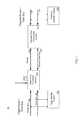
- FIG. 1illustrates a block diagram of an example distributed system architecture for an unmanned aerial vehicle (UAV).
- UAVunmanned aerial vehicle
- FIG. 2illustrates a block diagram of an example flight core processing system.
- FIG. 3illustrates a block diagram of an example payload core processing system.
- FIG. 4is a flowchart of an example process for dynamically negotiating power requirements of modules based on flight information of a UAV.
- FIG. 5is a flowchart of an example process for dynamically negotiating bandwidth usage of modules based on flight information of a UAV.
- FIG. 6is an illustration of a UAV entering different example flight phases.
- FIG. 7is an illustration of an example user interface generated by a configuration utility.
- FIG. 8Aillustrates an example user interface generated by the configuration utility for configuring and validating a UAV radio datalink.
- FIG. 8Billustrates an example user interface generated by the configuration utility for configuring and validating a UAV effector port mapping.
- FIG. 8Cincludes an example user interface generated by the configuration utility for configuring and validating radio control transmitter input settings.
- FIG. 8Dincludes an example user interface generated by the configuration utility for validating contingency identification thresholds and contingency response actions.
- FIG. 9is a flowchart of an example process for determining airworthiness of a UAV by the configuration utility.
- FIG. 10illustrates an example process for determining an estimated maximum flight endurance of a UAV.
- FIG. 11illustrates an example process for determining an estimated maximum flight radius of a UAV.
- FIG. 12illustrates a flowchart of an example process for determining an estimated maximum communication link range of a UAV.
- FIG. 13is a flowchart of an example process for processing a configuration file received from a cloud system.
- FIG. 14illustrates an example user interface identifying the processing of a configuration file received from a cloud system.
- the unmanned vehiclesmay include unmanned aerial vehicles (UAVs), such as drones, unpiloted aerial vehicles, remotely piloted aircraft, unmanned aircraft systems, any aircraft covered under Circular 328 AN/190 classified by the International Civil Aviation Organization, and so on.
- UAVsunmanned aerial vehicles
- the example distributed system architecturemay include a flight core processing system (e.g., a system in communication with flight critical systems and processes) in communication with (e.g., via one or more data buses and/or one or more power buses) a payload core processing system, e.g., a system in communication with one or more payload systems and processes).
- a flight core processing systeme.g., a system in communication with flight critical systems and processes
- a payload core processing systeme.g., a system in communication with one or more payload systems and processes.
- the example flight core processing systemmaintains power and/or bandwidth requirements of flight critical systems.
- a flight critical system or processmay include an aerial vehicle part, assembly, installation, or process containing a critical characteristic whose failure, malfunction, or absence could cause a catastrophic failure resulting in engine shut-down or loss or serious damage to the aerial vehicle resulting in an unsafe condition.
- the flight core processing systemcan switch off power and/or bandwidth to the payload core processing system, or limit the power and/or bandwidth available to the payload systems in communication with the payload core processing system.
- the payload core processing systemcan limit the power and/or bandwidth available to the payload systems by instructing the payload systems to enter lower power non-operational states.
- This distributed, e.g., separated, architectureallows for a UAV to have its flight-critical systems in flight ready condition with respect to power and/or bandwidth regardless of the number of payload systems that are included in the UAV.
- a malfunctioning payload systemcan draw too much power, or consume too much of the data buses bandwidth, such that the flight critical systems can malfunction.
- the distributed system architecturecan reduce, or limit, the occurrence of flight critical system failures.
- the UAVcan have payload systems replaced, modified, or removed, without the need for validation, verification, or re-certification of flight-critical systems.
- power usage and/or bandwidth usage of payload systemscan be modified depending on a UAV's flight phase, e.g., taxiing, launching, in-air flight, landing, and so on.
- the flight core processing systemcan provide information to the payload core processing system to provide full power requirements, and/or bandwidth requirements, to each payload system.
- particular payload systemscan be accorded full power and bandwidth, with superfluous payload systems (e.g., those that are currently not being actively used) accorded minimal bandwidth, and limited power.
- the distributed system architecturecan guard against power and/or bandwidth requirements, or anomalies, of a payload system negatively affecting flight critical systems.
- FIG. 1illustrates a block diagram of an example distributed system architecture 10 for an unmanned aerial vehicle (UAV).
- the distributed system architecture 10includes a flight core processing system 100 , e.g., a system in communication with flight modules 102 (e.g., a flight satellite system) which are critical to the safe operation of the UAV, connected to a payload core processing system 120 , e.g., a system in communication with payload modules 122 (e.g., a payload satellite system) which are not critical to the safe operation of the UAV.
- the connectionincludes a shared data bus 110 connection (e.g., a bus that can transmit data, messages, packets), and a power bus connection (e.g., a bus which provides power).
- a flight moduleis any system, module, or software process, that is critical to the safe flight operation of the UAV.
- the flight core processing system 100is configured as a central system hub for power and data, maintaining flight-critical systems and processes.
- the flight core processing system 100can ensure functional operation of the one or more flight modules 102 , e.g., some or all of the following: a global positioning system (GPS), other navigation sensors, a radio system, steering actuators, and so on.
- GPSglobal positioning system
- the flight core processing system 100can eliminate power to the payload core processing system 120 , e.g., over the power bus 112 , and disable the flight core processing system's 120 connection to the shared data bus 110 . In this way, the flight core processing system 100 can ensure that the flight modules 102 are provided with sufficient power and bandwidth for their safe operation.
- the flight core processing system 100can switch power 112 off to the payload core processing system 120 .
- the flight core processing system 100can disable the payload core processing system's 100 connection to the data bus 110 . In this way the flight core processing system 100 can ensure that flight modules 102 are not affected by malfunctioning payload modules 122 , or over-use of power and/or bandwidth.
- the flight core processing systemcan instruct the payload core processing system to reduce the power provided to one or more payload systems, such as by placing them in a lower power standby mode (which may result in a reduction in the performance and/or functionality of one or more payload systems), to thereby make more power available to the flight critical system.
- the flight core processing systemcan instruct the payload core processing system to reduce the data bandwidth utilized by one or more payload systems, such as by instructing the one or more payload systems not to access a data bus for a specified period of time or with a lower frequency, to thereby make more data bandwidth on the data bus available to the flight critical system.
- the flight core processing system 100can dynamically determine power and bandwidth requirements of the flight modules 102 , and provide information to the payload core processing system 120 identifying allowable power and bandwidth usage by payload modules 122 .
- the payload core processing system 120can then enforce the allowable power and bandwidth usage by providing information to payload modules 122 instructing the modules 122 to enter different power states, e.g., low-power states, based off current power usage by the payload modules 122 .
- the flight core processing system 100can obtain a current flight phase of the UAV, and provide information identifying the flight phase to the payload core processing system 120 .
- the payload core processing systemcan then obtain information associated with the flight phase, e.g., payload modules 122 that can be placed into a nominal power state to function normally and payload modules 122 that are to be placed in a low-power state with reduced functionality.
- a given payload module 122can also provide a request to the payload core processing system 120 to utilize bandwidth and/or power (e.g., a specified amount of bandwidth and/or power), which the payload module 122 can grant, or deny, based on, at least partly on, current flight phase or the acceptable power and/or bandwidth usage determined by the flight core processing system 100 .
- bandwidth and/or powere.g., a specified amount of bandwidth and/or power
- the flight core processing system 100 and payload core processing system 120can be complementary, with the payload core processing system 120 providing insights into the power and bandwidth associated with payload modules 122 , and the flight core processing system 100 providing insights into flight critical systems 102 .
- the bandwidth and power usage of the payload modules 122can be efficiently optimized to keep the flight critical modules 102 operating in a safe condition, e.g., with sufficient power and bandwidth usage, while disabling payload modules 122 when they are not needed to conserve battery life.
- FIG. 2illustrates a block diagram of the example flight core processing system 100 .
- the flight core processing system 100can be a system of one or more processors, logic circuits, analog circuits, associated volatile and/or non-volatile memory, associated input/output data ports, power ports, etc., and/or one or more software processes executing on one or more processors or computers.
- the flight core processing system 100is connected to one or more flight modules 102 via a flight power bus 104 and a flight data bus 106 .
- the flight data bus 106can include one or more data buses of various types, e.g., ETHERNET, UNIVERSAL SERIAL BUS (USB), UAVCAN, IEEE 1394b, MIL-STD-1553, and so on.
- ETHERNETETHERNET
- USBUNIVERSAL SERIAL BUS
- UAVCANUNIVERSAL SERIAL BUS
- IEEE 1394bIEEE 1394b
- MIL-STD-1553MIL-STD-1553
- two or more flight modules 102can be connected to the flight core processing system 100 , and other flight modules can be connected in series, e.g., daisy-chained, to one of the two or more flight modules 102 .
- the flight core processing system 100receives power, e.g., to power the flight power bus 104 , from an input power source, e.g., one or more batteries included in a UAV, or a power system that maintains one or more batteries.
- the example flight core processing system 100includes a flight critical processing engine 220 that can perform flight critical tasks, including one or more of baro-inertial measurements, inertial estimation and navigation, autonomous flight control, e.g., autopilot, and flight plan execution contingency identification and contingency flight plan execution, enumeration and management of flight modules 102 , in-system programming of flight modules 102 and the flight core processing system 100 itself, and/or recording and storing data logs.
- Data logscan include sensor data, navigation data, flight plans, system status information, system error information, contingency state information, and/or UAV system configuration data.
- the flight core processing system 100may be coupled to one or more sensors included in the UAV, such as accelerometers, barometric sensors, gyro sensors, temperature sensors, battery and/or current sensors, battery and/or other voltage sensors, flight surface position sensors, motor sensors, and/or other sensors.
- sensors included in the UAVsuch as accelerometers, barometric sensors, gyro sensors, temperature sensors, battery and/or current sensors, battery and/or other voltage sensors, flight surface position sensors, motor sensors, and/or other sensors.
- the flight critical processing engine 220can receive information, e.g., from a user operating a configuration utility, configuring an autopilot, flight modules 102 , and so on. The flight critical processing engine 220 can then provide the configuration information to respective flight modules 102 or other components of the UAV.
- the configuration utilityis described below, with reference to FIG. 7 .
- the flight core processing system 100includes a sensor measurement engine 210 , which can be in communication with one or more of the sensors disclosed herein.
- the sensor measurement engine 210may be in communication with an inertial measurement unit (IMU) including, for example, a MEMS (Micro-electromechanical system) 3-axis accelerometer sensor and MEMS 3-axis rate gyro sensor, and/or other type of accelerometer and gyro sensors.
- IMUinertial measurement unit
- An optional barometric pressure sensorcan also be included to measure barometric atmospheric pressure and one or more temperature sensors may be included to measure environmental temperature (e.g., air temperature) and/or the temperature of various modules and/or components (e.g., such as modules and/or components disclosed herein).
- Inertial and barometric sensorsmay be utilized by the sensor measurement engine 210 to correct for environmental conditions (such as temperature) by a applying a pre-determined calibration correction.
- the sensor measurement engine 210can execute an inertial estimation algorithm, e.g., a Kalman Filter or Extended Kalman Filter, which can estimate position, velocity, and/or attitude of the UAV using the inertial measurement unit and/or optional barometric pressure sensor.
- an inertial estimation algorithme.g., a Kalman Filter or Extended Kalman Filter, which can estimate position, velocity, and/or attitude of the UAV using the inertial measurement unit and/or optional barometric pressure sensor.
- the sensor measurement engine 210can obtain thermal measurements of the UAV, and obtain battery levels, e.g., voltage level, charge level, of one or more batteries powering the UAV. As will be described below, optionally if the thermal measurements exceed a threshold, or the battery levels are less than a threshold, the flight core processing system 100 can disable power usage by the non-flight critical payload modules.
- battery levelse.g., voltage level, charge level
- the flight core processing system 100includes a flight power management engine 230 which can adjust power to the payload core processing system 120 , to ensure that any flight critical modules 102 receive full power requirements.
- the flight power management engine 230is configured to dynamically negotiate power usage and requirements with the payload core processing system 230 , and also to sever the power connection to the payload core processing system 120 upon determining the payload core processing system 120 , or a payload module 122 , is malfunctioning. Furthermore, the flight power management engine 230 can regulate the voltage level of power 112 provided to the payload core processing system 120 , condition the power 112 to suppress or remove transient voltage anomalies, and measure power current power and current usage of the payload core processing system 120 .
- the flight power management engine 230can disable power to the payload core processing system 120 upon determining that the power usage of the payload core processing system 120 endangers the safe flight operation of the UAV. For instance, the flight power management engine 230 can obtain information identifying that a battery level of the UAV, e.g., a level of one or more batteries powering the UAV, is below a threshold. Optionally, the threshold can be determined dynamically, e.g., based on a remaining flight time and power requirements of the flight modules 102 .
- a given thresholdmay be pre-specified, but may optionally be dynamically modified based at least in part on current flight related parameters (e.g., one or more of: remaining flight time, battery charge remaining, air temperature, other sensor measurements, payload sensor readings that still need to be taken, power requirements of the flight modules 102 , etc.)
- current flight related parameterse.g., one or more of: remaining flight time, battery charge remaining, air temperature, other sensor measurements, payload sensor readings that still need to be taken, power requirements of the flight modules 102 , etc.
- the power management engine 230can disable power to the payload core processing system 120 upon determining that the payload core processing system 120 is consuming too much power or battery charge, e.g., a payload module is malfunctioning causing a short-circuit or over-current condition.
- the power management engine 230can disable power to the payload core processing system 120 upon determining that one or more thermal states of the UAV, e.g., system temperature of the batteries, processing systems, modules 102 and 122 , and so on, exceed a threshold. In this way, the flight power management engine 230 can prevent damage to the UAV's electrical systems, e.g., flight critical modules 102 .
- the flight power management engine 230can provide information identifying a reduced acceptable power usage to the payload core processing system 120 . For instance, if the flight power management engine 230 determines that one or more thermal states exceed a threshold, the flight power management engine 230 can reduce the acceptable power usage of the payload modules until the thermal states normalize.
- the flight power management engine 230can communicate with the flight modules 102 , and the payload core processing system 120 .
- the communicationscan include, the flight core processing system 100 receiving electrical power requirements for flight modules 102 and payload modules 122 , e.g., minimum electrical power, nominal electrical power, maximum electrical power, electrical power requirements of one or more states of each module, etc.
- the flight core processing system 100can identify power requirements of some or all of the connected modules 102 and 122 .
- the payload core processing system 120can provide requests to increase its acceptable power usage, e.g., the system 120 can receive requests from payload modules 122 to be placed in a full power state.
- the flight power management engine 230can determine whether the request can be safely granted, e.g., based off power requirements of flight critical modules 102 .
- the flight power management engine 230can also provide information to flight modules 102 to place them in a low power state, e.g., depending on the current flight information. For instance, one or more flight critical modules 102 might be required for the safe take-off or safe landing of the UAV, but not for safe operation in an on-station flight phase, e.g., a phase during which the UAV remains in a particular flight path. Therefore, the flight power management engine 230 can safely place the unneeded flight modules 102 in a low power state, and provide information to the payload core processing system 120 identifying a greater acceptable power usage.
- power states of payload modules 122can be modified according to a current flight information of the UAV, e.g., flight phase, contingency state, and so on.
- the flight power management engine 230can obtain the current flight phase, e.g., from the flight-critical processing engine 220 , and provide the current flight phase to the payload core processing system 120 .
- the payload core processing system 120can then modify the power states of connected payload modules 122 according to the flight phase.
- bandwidth requirementsinclude the use of the data bus 110 for a period of time or over a period of time, and can include providing data messages, packets, and so on, to the shared data bus 110 for receipt by another module or processing system.
- a camera payload modulecan provide a large amount of data on the shared data bus 110 to be provided to a radio module for transmission to a remote radio destination, such as a ground station or other aerial or ground vehicle.
- the flight core processing system 100includes a flight bandwidth management engine 240 that can restrict the payload core processing system's 120 use of the shared data bus 110 . Additionally, the flight bandwidth management engine 240 can prioritize use of the shared data bus 110 by flight modules 102 , e.g., at the expense of non-flight critical payload modules 122 .
- the flight bandwidth management engine 240can prioritize, restrict, throttle (e.g., reduce the accessible bandwidth to a certain number of bytes per second), increase latency, or prevent delivery of, data messages emanating from particular payload modules 122 . As will be described below with reference to FIG.
- the flight bandwidth management engine 240can enforce bandwidth restrictions depending on flight status (e.g., particular payload modules 122 can be blocked when they are not needed), flight phase (e.g., payload modules 122 can be blocked from use of the data bus 110 during a take-off phase), contingency state of the UAV (e.g., payload modules 122 that desire to transmit data through a radio can be blocked from use of the data bus 110 during a “Lost GPS” contingency state, in an effort to reduce radio frequency transmission interference so that a GPS signal lock can be obtained), and so on.
- flight statuse.g., particular payload modules 122 can be blocked when they are not needed
- flight phasee.g., payload modules 122 can be blocked from use of the data bus 110 during a take-off phase
- contingency state of the UAVe.g., payload modules 122 that desire to transmit data through a radio can be blocked from use of the data bus 110 during a “Lost GPS” contingency state, in an effort
- the flight bandwidth management engine 240can prioritize, restrict, throttle, increase latency, or prevent the delivery of all data messages, or a particular type of data message, being sent to or from a particular software process. Additionally, the flight bandwidth management engine 240 can prioritize, restrict, throttle, increase latency, or prevent the delivery of data messages being sent to or from a specific class of module, e.g., all flight critical modules or payload modules.
- the flight bandwidth management engine 240can prioritize, restrict, throttle, increase latency, or prevent all messages, or a specific type of data message, from being transmitted over the shared data bus 110 until the flight bandwidth management engine 240 halts such prioritization, restriction, throttling, increase in latency, or prevention or for a specified period of time.
- FIG. 3illustrates a block diagram of the example payload core processing system 120 .
- the payload core processing system 120can be a system of one or more processors, logic circuits, analog circuits, associated volatile and/or non-volatile memory, associated input/output data ports, power ports, etc., and/or one or more software processes executing on one or more processors or computers.
- the payload core processing system 120receives power 112 from the flight core processing system 100 , and can communicate with the flight core processing system 100 via a shared data bus 110 .
- the payload core processing system 120controls a payload power bus 124 , e.g., one or more power buses with different power/voltage characteristics, and a payload data bus 126 , e.g., one or more types of data buses such as ETHERNET and UNIVERSAL SERIAL BUS, UAVCAN, IEEE 1394b, MIL-STD-1553, etc., which one or more payload modules 122 are connected to. Since each payload module 122 can require a particular power characteristic, e.g., operational voltage level, and particular data bus connection to be functional, the payload core processing system 120 includes disparate types of power buses 124 and payload buses 126 .
- a payload power bus 124e.g., one or more power buses with different power/voltage characteristics
- a payload data bus 126e.g., one or more types of data buses such as ETHERNET and UNIVERSAL SERIAL BUS, UAVCAN, IEEE 1394b, MIL-STD-1553, etc.
- the payload core processing system 120includes a payload processing engine 320 which can perform enumeration, configuration, and in-system programming of connected payload modules 122 , e.g., via the payload data bus 126 .
- the payload processing engine 320can determine, at least in part, when payload modules 122 can be programmed based on several factors, including flight state (e.g., In-Air, On-Ground, Active, Inactive), system error conditions, hardware compatibility of payload modules 122 being programmed, firmware image validity, firmware image signature mismatch, and software license validity.
- the payload processing engine 320can prevent in-system programming to occur on selected payload modules 122 while the UAV is in-flight.
- the payload processing engine 320can communicate with a configuration utility, e.g., operated by a user, which can provide configuration and programming information to the payload modules 122 .
- the configuration utilityis described below, with reference to FIG. 7 .
- the payload core processing system 120includes a payload power management engine 310 which can place one or more of the modules 122 in distinct power states, e.g., low-power, nominal power, high-power, and negotiate power usage by the payload modules 122 with the flight core processing system 100 .
- a payload power management engine 310which can place one or more of the modules 122 in distinct power states, e.g., low-power, nominal power, high-power, and negotiate power usage by the payload modules 122 with the flight core processing system 100 .
- the payload core processing system 120can receive information, e.g., from the flight core processing system 100 , identifying a current flight phase of the UAV. In response to this received information, the payload power management engine 310 can obtain information identifying payload modules 122 and associated acceptable power states for the received flight phase. The payload power management engine 310 can then provide requests, e.g., over the payload data bus 126 , to the payload modules 122 for the payload modules 122 to be placed in the acceptable power states.
- the payload power management engine 310can obtain information identifying power states of payload modules 122 for the on-station phase. This can include all, or specific, payload modules 122 being allowed to operate in full-power states.
- the payload power management engine 310can receive, e.g., from the flight core processing system 100 , information identifying an acceptable power usage by the payload core processing system 120 .
- the payload power management engine 310can determine the current power and/or current usage, e.g., on the payload power bus 124 , and modify power states of particular payload modules 122 to bring the usage of the power bus 124 in conformance with the received acceptable power usage.
- the payload power management engine 310can receive requests from payload modules 122 to be placed in a higher power state, and determine whether the higher power state would cause the power bus 124 to be using more power than is allotted it by the flight core processing system 100 . Upon a positive determination, the payload power management engine 310 can deny the request, or place a different payload module 122 in a low power mode, and grant the request. In some implementations, each payload module 122 can be allotted a particular amount of time in which it operates in a full power state, or the payload modules 122 can be associated with a hierarchy. The payload power management engine 310 can prefer to place payload modules 122 in a full power state based on each module's 122 location in the hierarchy. In this way, the payload power management engine 310 can operate within safe acceptable power usage guidelines set by the flight core processing system 100 .
- the payload power management engine 310can determine that a particular payload module 122 is malfunctioning, e.g., consuming too much power or current, and provide a request to the payload module 122 to turn-off. If the malfunctioning payload module 122 is unable to process the request, the payload power management engine 310 can shut off power to the payload power bus 124 . Alternatively, the payload power management engine 310 can provide information to the flight core processing system 100 identifying that the system 100 should sever power connection 112 entirely to the payload core processing system 120 .
- the payload management engine 310can also store information identifying a history of electrical faults of particular payload modules 122 , e.g., short-circuit or over-current conditions. Upon determining that a payload module 122 has experienced an electrical fault greater than a pre-specified or dynamically determined threshold, e.g., 2 times, 3 times, 5 times, the payload power management engine 310 can provide a request for the particular payload module 122 to turn off.
- a pre-specified or dynamically determined thresholde.g., 2 times, 3 times, 5 times
- the payload core processing system 120further includes a payload bandwidth management engine 330 which can negotiate bandwidth requirements, e.g., use of the shared data bus 110 , of the payload modules 122 .
- a camera payload module 122can provide a large amount of data, e.g., data messages or packets, on the shared data bus 110 , e.g., one or more images or video streams.
- the payload bandwidth management engine 330can ensure that this large amount of data is only placed on the shared data bus 110 at times when it will not affect the safe operation of flight-critical modules.
- a malfunctioning payload module 122might block use of the shared data bus 110 .
- the payload bandwidth management engine 330can block use of the shared data bus by the malfunctioning payload module 122 .
- the payload bandwidth management engine 330may specify that a given payload module 122 may only communicate a specified maximum amount of data over a specified time period (e.g., a specified data rate of transmission). Thus, for example, the camera payload module 122 may be instructed to slowly transmit photographs over the shared data bus 110 (e.g., a specified maximum number of megabytes per second, or other amount of data over other period of time), rather than attempt to transmit photographs over the shared data bus 110 in a burst or at a faster rate.
- a specified maximum amount of data over a specified time periode.g., a specified data rate of transmission.
- the payload bandwidth management engine 330receives information, e.g., from the flight core processing engine 100 , identifying that the payload bandwidth management engine 330 is to throttle, increase latency, restrict, use of the shared data bus 110 .
- the payload bandwidth management engine 330can receive information identifying a particular flight phase, e.g., in-flight, and throttle, increase latency, or restrict, use of the shared data bus 110 by particular payload modules 122 that are not needed during the particular flight-phase.
- the payload bandwidth management engine 330can allow full use of the shared data bus 110 by payload modules 122 .
- the payload bandwidth management engine 330can also prevent delivery of data messages provided from particular payload modules 122 .
- data messages directed to the flight core processing system 100 from a payload module 122can overwhelm the flight core processing system 100 , e.g., causing a denial of service.
- the payload bandwidth management engine 330can cause these data messages to not be delivered.
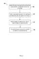
- FIG. 4is a flowchart of an example process 400 for dynamically negotiating power requirements of modules based at least in part on flight information of a UAV.
- the process 400will be described as being performed by a system of one or more processors, e.g., the distributed system architecture 10 .
- Flight informationcan include an identification of the phase in a flight progression (e.g., on-station, taxiing, launch phase, landing phase), a contingency state of the UAV if it encounters an error (e.g., low fuel, lost GPS, lost radio link), or a status of the UAV (e.g., on-ground, in-configuration, in-flight).
- a flight progressione.g., on-station, taxiing, launch phase, landing phase
- a contingency state of the UAV if it encounters an errore.g., low fuel, lost GPS, lost radio link
- a status of the UAVe.g., on-ground, in-configuration, in-flight.
- the UAVcan store information identifying the progression.
- the systemcan then obtain the information, and determine the present flight phase.
- the systemcan obtain the current flight phase, for example, in response to a change in the progression of flight phase of the UAV.
- the systemcan determine a contingency state of the UAV by identifying a system warning or error related to a flight critical system or module e.g., based on one or more data messages and/or sensor readings.
- the systemobtains power usage by modules (block 404 ).
- the systemobtains current power usage of flight critical modules, and payload modules. For instance, the system can determine the total output power of connected flight critical modules, e.g., the flight core processing system 100 can determine the total output power, and also determine the total output power of payload modules, e.g., the payload core processing system 120 can determine the total output power.
- the systemprovides updated power states to one or more of the payload modules (block 406 ).
- the systemmodifies the power states of one or more of the modules based off the flight information.
- the systemcan store information identifying acceptable power states of modules with regards to flight information.
- the systemcan obtain information identifying that during an “on-station” flight phase, all of the payload modules are to be accorded nominal power states so that they can function normally. However, during a “landing”, “returning to base”, “climbing”, “descending”, and so on, flight phase, the system can provide information to one or more payload modules to enter a low power or power-off state as they are not needed.
- the systemcan obtain information identifying that during a “Lost GPS” contingency state, the system is to place payload modules that can interfere with obtaining a lock on a GPS signal in a low-power or power-off non-functional state to prevent or reduce such interference.
- the systemcan obtain information identifying an acceptable power usage by payload modules.
- the acceptable power usagecan depend at least in part on flight information, and can, for example, be greater during an “on-station” flight phase, or an “in-configuration” status, e.g., a status identifying that each payload module is to be in nominal power state to receive configuration information.
- the systemcan then provide information to one or more payload modules to enter a nominal power state, and thus to consume power.
- Providing informationcan include, receiving a request from one or more payload modules to enter nominal power states, and providing a response granting the requests, or providing a direct request for one or more payload modules to enter nominal power states.
- the systemdetermines that the acceptable power usage does not allow for all payload modules to enter a nominal power state, it can identify particular payload modules that can enter normal operation.
- the systemcan store information identifying allowed payload modules for particular flight information.
- the systemcan store a hierarchy of payload modules, and configure one or more payload modules for normal operation based off their hierarchy that consume less than or equal to the acceptable power usage.
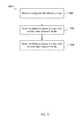
- FIG. 5is a flowchart of an example process 500 for dynamically negotiating bandwidth usage of modules based at least in part on flight information of a UAV.
- the process 500will be described as being performed by a system of one or more processors, e.g., the distributed system architecture 10 .
- the systemobtains information identifying flight information of the UAV (block 502 ).
- An example process of obtaining flight informationis described above, with reference to FIG. 4 .
- the systemobtains bandwidth usage by modules (block 504 ).
- the systemdetermines a bandwidth usage of the flight critical modules and the payload modules. Since many of the flight critical systems need sufficient bandwidth to remain functional, the system determines a measure of central tendency of bandwidth (e.g., mean, median, mode, geometric mean, harmonic mean, weighted mean, truncated mean, midrange mean, trimean, winsorized mean, etc.) use by the flight critical modules, and additionally peak bandwidth usage by the flight critical modules.
- a measure of central tendency of bandwidthe.g., mean, median, mode, geometric mean, harmonic mean, weighted mean, truncated mean, midrange mean, trimean, winsorized mean, etc.
- the systemadjusts the bandwidth usage of payload modules based on the obtained flight information (block 506 ).
- the systemcan restrict, throttle, increase latency, or prevent the delivery of data messages being sent to or from payload modules based on the flight information. That is, the system can provide information to specific payload modules identifying that they are not to place any data messages on, or consume bandwidth of, the data bus, e.g., the shared data bus 110 .
- the systemcan also receive data messages placed on the data bus by one or more payload modules and cause the messages to not be delivered to their intended target or not to be delivered for a certain period of time (thereby increasing latency).
- the systemcan store data messages provided by payload modules in a data structure, e.g., a queue, and provide the data messages to their intended targets upon the occurrence of a different flight phase, e.g., a camera taking pictures during landing can provide its images after the plane lands.
- a data structuree.g., a queue
- the systemcan prioritize data messages from flight modules, e.g., at the expense of data messages from payload modules. Prioritization can include the system processing, or providing, the data messages prior to non-prioritized data messages emanating from remaining modules.
- the systemcan obtain information identifying acceptable bandwidth usage of payload systems given the obtained flight information. For instance, the system may restrict data messages from being placed on a data bus, or prevent delivery of the messages, emanating from superfluous payload modules that are not currently needed during an “in-flight” flight phase, but allow full message delivery during an “in-configuration” UAV status. Similarly, the system can restrict or throttle data message delivery of payload modules during a “launch” flight phase, but grant all bandwidth requests, e.g., not restrict or throttle data messages, during an “on-station” flight phase.
- the systemdetermines the acceptable bandwidth usage, in part, with the bandwidth usage of the flight modules.
- the systemcan ensure that the acceptable bandwidth usage by the payload modules does not interfere with the peak bandwidth usage of the flight critical modules.
- the systemcan ensure that the acceptable bandwidth usage by the payload modules does not interfere with the average (or other central tendency) bandwidth usage of the flight critical modules.
- FIG. 6is an illustration of an example UAV entering and leaving different flight phases.
- the illustrationincludes an example UAV 602 in different phases of its flight progression.
- the UAV in this exampleincludes two payload module, e.g., camera system 606 , and radio system 604 .
- the radio system 604transmits, and receives, data and messages from the camera system 606 to, and from, communication systems outside of the UAV, e.g., ground based control systems.
- the first flight phase 610e.g., the launch phase, is illustrated as the UAV 602 launching into the air.
- a systeme.g., the distributed architecture system 10
- the systemcan then obtain information (e.g. from memory and/or by querying the payload modules) identifying payload modules and permitted power usage and bandwidth usage.
- the systemhas determined that the two payload modules, e.g., the camera system 604 and radio system 606 , should not be consuming power or using bandwidth during the first flight phase 610 , instead devoting full power and bandwidth to flight critical systems.
- the UAVAfter launching, the UAV enters an “on-station” flight phase 620 . As illustrated, the system has obtained information identifying that during an on-station flight phase, the UAV is permitted full use of its payload modules. As similarly described with respect to FIGS. 4 and 5 , the system provides information to the two payload modules identifying that they can enter a nominal power state, and utilize nominal bandwidth, to start properly functioning.
- the UAVhas entered a contingency state identifying the GPS signal is lost 630 , which in this example is a flight-critical system.
- the systemhas obtained information identifying that during the contingency state 630 , the UAV is to disable data messages being provided to any payload radio systems, e.g., the radio system 604 . This ensures that the radio system 604 does not transmit unnecessarily and create interference.
- the camera system 606can remain functioning, e.g., at a nominal power state, however the system will cause its bandwidth use to be partially eliminated, e.g., by causing delivery of its data messages to the radio system 604 to fail.
- the UAVAfter regaining GPS signal, the UAV enters a “landing phase” flight phase 640 . Similar to the launch phase 610 , during a landing phase the system obtains information identifying that payload modules should enter low power states and not utilize bandwidth.
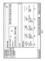
- FIG. 7is an illustration of an example user interface generated by an example configuration utility 700 .
- the configuration utility 700is a tool for configuring a UAV (e.g., an autopilot, connected payload and flight modules), which can generate user interfaces and provide information for presentation to a user and which can receive information, menu selections, and instructions from the user.
- the configuration utility 700executes on a system separate from the UAV, which connects to the UAV, e.g., wirelessly or through a wired connection to the distributed system architecture 10 , and provides capabilities to modify the UAV's configuration online (while connected) or offline (running independently of the autopilot or modules).
- the configuration utility 700can be run on the UAV, e.g., the distributed system architecture 10 , which provides a user interface for presentation on a display connected to the UAV.
- the UAVcan be placed in an “in-configuration” status, which provides full power and bandwidth requirements to payload modules, e.g., described above.
- the configuration utility 700identifies the autopilot, payload and/or flight modules, and information describing each module, e.g., some or all of the following: SKU, model, serial number, current configuration, capabilities, power usage, data bandwidth usage, flight criticality (e.g., how critical the module is for flight safety), and/or other information.
- the configuration utility 700has identified a name and serial number 702 of the UAV, e.g., Tarot FY650 with serial#1.” Additionally, the configuration utility 700 has identified five modules included in the UAV, including a GPS module 704 , two Actuator modules 706 and 708 , an Air Datalink module 710 , and a flight core module 712 .
- the configuration utility 700is configured to assist in configuring a UAV, including the UAV's autopilot, and flight/payload modules.
- the configuration utility 700can validate configurations of a UAV to ensure correct functionality of the UAV during flight.
- the configuration utility 700can walk a user through the configuration process, e.g., providing one or more easy to use user interfaces described below.
- the configuration utility 700can provide user interfaces to guide a user in enabling, and configuring, components of the UAV. For instance, the configuration utility 700 can configure an autopilot, such as controller setup, gain selection, and aircraft type selection. Additionally, the configuration utility 700 can configure an actuator module port configuration, actuator limit settings, actuator type and protocol settings, and so on (e.g., for a flight surface actuator, for a landing gear actuator, for a parachute actuator, etc.).
- the configuration utility 700can configure a GPS module, a magnetometer configuration (e.g., including hard-iron and soft-iron magnetic calibration), datalink module configuration (e.g., frequency/band settings, Internet Protocol settings, transmission power settings, net mask settings, mesh networking settings), and/or payload module configuration (e.g., gimbal camera control module calibration).
- a magnetometer configuratione.g., including hard-iron and soft-iron magnetic calibration
- datalink module configuratione.g., frequency/band settings, Internet Protocol settings, transmission power settings, net mask settings, mesh networking settings
- payload module configuratione.g., gimbal camera control module calibration
- the configuration utility 700can also provide feedback to the user/operator to make improvements or adjustments to a selected configuration, and optionally enforce certain restrictions to prevent invalid or dangerous configurations from being loaded onto a UAV.
- menuse.g., drop down menus, flyout menus, accordion menus or other menus, which may optionally present currently valid options
- text fieldse.g., text fields, or otherwise.
- FIG. 8Aillustrates a user interface 800 generated by the configuration utility for configuring and validating a UAV radio datalink, e.g., a flight critical datalink or a payload datalink.
- the user interface 800includes selectable options 802 , e.g., frequency selection, transmission power selection, and bandwidth selection, with each selectable option displaying options compatible with the specific manufacturer, model, and capabilities of the radio datalink.
- the configuration utilitycan store, or have access to, information describing UAV components, including in this example, a radio datalink.
- the configuration utilitycan ensure that a ground datalink includes complementary settings to the UAV radio datalink. That is, the configuration utility can connect to a ground based system, and present a user interface with selectable options already selected based on the UAV selections 802 .
- the user interface 800includes an explanation of the datalink settings 804 , including identifying that both the ground datalink and the UAV datalink will be automatically configured with the same settings. In this way a user of the user interface 800 can understand which options to select, and feel confident that the configuration utility will effect a functional UAV.
- the usercan select option 806 , e.g., “Apply to Aircraft,” to apply the selectable options 802 to the UAV datalink.
- option 806e.g., “Apply to Aircraft”
- the datalinkis placed in an “in-configuration” status, and the selected options 802 are provided to the datalink.
- the usercan also save the current configuration, or load a previous configuration 808 with an identifier (e.g., a configuration name, a unique alphanumeric code, etc.).
- a search interfacemay be provided enabling a user to submit a configuration search query to a configuration utility search engine.
- the configuration utility search enginemay identify matching saved configuration files, and may present a listing of such matching configuration files to the user.
- the usercan select a given configuration file from the listing, and the configuration utility may present the selected configuration file to the user via a corresponding configuration user interface.
- the usermay modify the selected configuration file and optionally save the modified configuration file with a different identifier.
- FIG. 8Billustrates a user interface 810 generated by the configuration utility for configuring and validating a UAV effector port mapping for one or more actuator control modules.
- the user interface 810accesses and displays determined information, such as what ports of a given actuator control module are connected, to what devices the actuator control module ports are connected to, to which inputs of the connected devices the actuator control module ports are connected to, what is the port mode, if the mode is Pulse Width Modulation what is the Port Pulse Width Modulation rate for a given connected device, and which power bus (e.g., a flight critical power bus or a non-flight critical power bus) is used to power a given connected device.
- the usermay specify or modify the various channel mappings and modes via the example user interface 810 .
- the user interface 810identifies via attached device fields 812 four motors, e.g., Motors 1-4, attached to a first actuator control module (Actuator Control Module v1.0.6, ID:207) and identifies, via a mode interface, that the four motors are powered using a pulse width modulated output.
- the user interfacefurther identifies, via a Port Pulse Width Modulation rate interface 814 , a pulse width modulation rate, e.g., “400 Hz.”
- the user interfacefurther identifies, via a power bus interface 816 , that pulse width modulated power applied to the motors connected to the first actuator control module (Actuator Control Module v1.0.6, ID:207) is provided over the flight critical power bus, e.g., described above with reference to FIGS. 1-2 .
- the UAVcan ensure that the motors are always given power as they require it, e.g., by reducing power to payload modules described in FIG. 4 .
- the user interface 810 in this examplealso identifies via attached device fields 818 that an SBUS Device SBUS input, is attached to port 1 of a second actuator control module (Actuator Control Module v1.0.6, ID:475), and identifies, via a mode interface, that the SBUS Device is powered using a pulse width modulated output.
- the user interfacefurther identifies, via a Port Pulse Width Modulation rate interface 820 , a pulse width modulation rate, e.g., “400 Hz.”
- the user interfacefurther identifies, via a power bus interface 822 , that pulse width modulated power applied to the SBUS device connected to the second actuator control module (Actuator Control Module v1.0.6, ID:475) is provided over the flight critical power bus.
- the configuration utilityUpon a user selection of “Apply to Aircraft,” the configuration utility checks the above selections for validity, e.g., ensuring every motor is assigned to an actuator port, ensuring no motor is assigned to more than one port, and ensuring the pulse width modulation rate and power bus 816 have both been selected and are at a frequency supportable by the UAV.
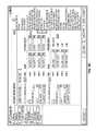
- FIG. 8Cincludes an example user interface 820 generated by the configuration utility for configuring and validating radio control transmitter input settings.
- This user interface 820allows a user to map a controller, e.g., a joystick, to specific channels of a radio on a UAV.
- the example user interface 820accesses and displays determined information, such as control mapping (e.g., the mapping of roll, pitch, yaw, and throttle commands to respective channels, and an indication as to whether a given channel is to be inverted), a mapping of switch functions (e.g., the mapping of kill, control select, manual mode select to respective channels), and an indication of the switch functions respective modes, and an indication as to whether a given switch channel is to be inverted.
- control mappinge.g., the mapping of roll, pitch, yaw, and throttle commands to respective channels, and an indication as to whether a given channel is to be inverted
- switch functionse.g., the mapping of kill, control select, manual mode select to respective channels
- an interfacemay be provided enabling the calibration of a radio control transmitter with respect to the control of throttle, pitch, and/or roll.
- the usermay specify or modify the various channel mappings and modes via the example user interface 820 .
- the systemmay map a given specified resulting action to one or more specified flight plans.
- the example user interface 820identifies four commands 822 , e.g., Roll, Pitch, Throttle, and Yaw, mapped to four selectable channels, e.g., channels 1-4.
- the user interfacealso indicates whether one or more channels are inverted.
- the user interface 820further includes range calibration of the controller, by a user selecting the start calibration option 824 .
- the user interface 820includes one or more switches on the controller that are configured to trigger particular functionality, including an emergency shutoff of all motors 824 , an autonomous flying option 826 , and a manual flying option 828 .
- the usermay specify or modify the various channel mappings and modes via the example user interface 820 .
- the configuration utilityvalidates the selections by ensuring that ensuring that each command 822 and switch 824 - 828 is mapped to a valid and active radio control channel.
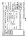
- FIG. 8Dincludes an example user interface 830 generated by the configuration utility for validating contingency identification thresholds and contingency response actions.
- the user interfaceincludes an identification of various contingencies 832 , e.g., “Lost RC link”, “Lost Datalink”, “Low voltage”, “Critical Voltage”, “Geofence Excursion”, mapped to minimum thresholds 834 that need to occur before a resulting contingency action 836 is taken by the UAV (e.g., return to home, loiter, and land; return to home and land; land now, etc.).
- various contingencies 832e.g., “Lost RC link”, “Lost Datalink”, “Low voltage”, “Critical Voltage”, “Geofence Excursion”, mapped to minimum thresholds 834 that need to occur before a resulting contingency action 836 is taken by the UAV (e.g., return to home, loiter, and land; return to home and land; land now, etc.).
- the example user interface 830indicates that the contingency settings specify that if the UAV determines that it has lost a radio control link for greater than or equal to 0.5 seconds, the UAV is to alter its flight information to return to home, loiter, and land.
- the usermay specify or modify the various thresholds and resulting actions via the example user interface 830 .
- the configuration utilityvalidates each threshold 834 using pre-defined range limits for the associated parameter.
- the configuration utilitychecks the response actions 836 for validity by constraining the available selection options to only those that are applicable to the contingency.
- the only allowable response for Critical Battery Voltageis “Land Now”, since the UAV is critically low on available battery power and cannot travel to a pre-specified home location before landing.
- FIGS. 8A-8Ddescribe examples of the configuration utility validating configurations of components, or behaviors, of the UAV and of interfaces via which a user can modify certain configurations or behaviors.
- This validationoptionally includes validation of certain or all configuration parameters, including configuration parameters for UAV type, UAV layout, control parameters, safety and contingency settings, and/or others. Each parameter is optionally validated to be a reasonable value both in terms of absolute range, but also consistent with other parameter settings where applicable.
- the configuration utilitycan also validate the configuration against specified or detected software, hardware, and firmware, of the UAV, to ensure that the configuration is correct and will behave properly.
- FIG. 9is a flowchart of an example process 900 for determining airworthiness of a UAV by the configuration utility.
- the configuration utilityanalyzes information, e.g., type of UAV, aircraft calibration, detected flight and payload modules, configuration parameters, and/or UAV safety and contingency settings, to determine whether the UAV and the UAV's configuration are determined to be safe and airworthy.
- informatione.g., type of UAV, aircraft calibration, detected flight and payload modules, configuration parameters, and/or UAV safety and contingency settings
- the example configuration utilityobtains information associated with each flight and payload module, and determines whether any errors exist (block 902 ).
- the configuration utilityobtains information identifying some or all flight and payload modules that are connected, and properly receiving and providing data, to the UAV. For example, the configuration utility may query the UAV (e.g., by transmitting a request to the flight core processing system and/or the payload core processing system) for such information. The configuration utility then compares such information against a list flight and payload modules (e.g., a list of all flight and payload modules) that are supposed to be connected to the UAV. Optionally, the list can be included in a previously generated configuration file, which identifies configuration information of the UAV and associated flight/payload modules. Upon determining any discrepancy, the configuration utility provides, for presentation to a user, error information identifying one or more flight and/or payload modules that were not detected in the UAV but that are supposed to be present and connected.
- a list flight and payload modulese.g., a list of all flight and payload modules
- the listcan be included in a previously generated configuration file, which identifies configuration
- the configuration utilityis optionally configured to provide information to a given flight and payload module to perform a self-test and report any errors back. If the configuration utility receives any errors, error information identifying the error is provided for presentation to the user.
- the configuration utilityobtains a list, e.g., from a configuration file, of identifying information, such as serial numbers, associated with the flight and payload modules that are supposed to be in the UAV, and checks whether the identifying information (e.g., serial numbers) are in conformance to identifying information (e.g., serial numbers) of the flight and payload modules actually in the UAV. If the configuration utility determines that a flight or payload module is associated with a serial number different than a serial number on the list, the configuration utility provides information identifying the discrepancy to the user.
- identifying informationsuch as serial numbers
- the configuration utilityobtains identifications of firmware, or other software, versions associated with the flight and payload modules in the UAV.
- the configuration utilitychecks these identifications against firmware, other software, versions identified in the previously generated configuration file. If the configuration utility determines there any discrepancies, the configuration utility provides information identifying the discrepancy to the user.
- any error or discrepancy, or alternatively certain errors or discrepancy identified as critical, determined, or identified, by the configuration utilitycauses the UAV to fail the airworthiness test.
- the configuration utilityobtains configuration information from each flight and payload module, and validates it, e.g., described above with reference to FIG. 8A-8D (block 904 ). As described in FIG. 8A-8D , the configuration utility can validate configuration settings selected for particular components of the UAV.
- the configuration utilityvalidates the configuration. If the configuration utility determines any configuration settings are invalid, the user is provided with a user interface, e.g., user interfaces 800 , 810 , 820 , 830 , configured to allow for the changing of particular configuration settings.
- a user interfacee.g., user interfaces 800 , 810 , 820 , 830 , configured to allow for the changing of particular configuration settings.
- the configuration utilityAfter the user changes the configuration settings, the configuration utility re-validates the configuration, and determines whether the configuration of each component is valid. Upon a negative determination, the configuration utility provides information to the user identifying that the UAV did not pass the airworthiness test.
- the configuration utilityprovides any updated configuration information to respective flight and payload modules (block 906 ).
- the configuration utilityprovides any updates to configuration information of any flight or payload module that had to be re-validated in step 904 .
- the configuration utilityoptionally computes a checksum e.g., a hash sum, of the configuration information, and directs each receiving flight or payload module to compute a same checksum upon receipt of the configuration information.
- the flight or payload modulesthen provide the computed checksum to the configuration utility, which determines whether there are any discrepancies.
- the configuration utilityUpon a positive determination, the configuration utility provides the configuration to the flight or payload modules, until the checksum values agree.
- each flight or payload module receiving updated configuration informationperforms a self-test procedure. If the configuration utility receives an identification of an error resulting from the self-test procedure, the airworthiness test fails.
- the configuration utilityprovides information to the user identifying the successful completion of the airworthiness test (block 908 ).
- FIG. 10illustrates an example process 1000 for determining an estimated maximum flight endurance of a UAV, e.g., based on its current configuration.
- the example process 1000will be described as being performed by the configuration utility, described above.
- the configuration utilityobtains configuration information of flight and payload modules included in the UAV (block 1002 ).
- the configuration utilityreceives the configuration information, and generates a configuration file identifying each payload and flight module, e.g., with associated configuration information and/or weight information, and information describing the UAV, e.g., UAV type, battery type and chemistry, and so on.
- the configuration utilitycomputes a total flight weight of the UAV (block 1004 ).
- the configuration utilitycomputes the total flight weight from a weight of all flight and payload modules, weight of UAV batteries, and weight of the UAV airframe.
- the systemidentifies each flight and payload module in the configuration file, and sums the associated weights.
- the configuration utilityoptionally estimates the weight based on parameters including some or all of the following: battery chemistry, voltage and energy capacity parameters, e.g., obtained from the configuration file.
- the configuration utilityobtains information identifying batteries (e.g., commonly available commercial off-the-shelf (COTS) batteries) mapped to its weight.
- the configuration utilityidentifies a battery (e.g., a suitable COTS battery) with closest parameters, and obtains the estimated weight of the UAV batteries as the weight of the closest COTS battery.
- an interfaceis provided via which the user can directly input the weight of the batteries.
- the configuration utilityoptionally estimates the weight using the aircraft type, e.g., multi-rotor helicopter, conventional fixed-wing, flying wing, and so on.
- the configuration utilityobtains information from a data source (e.g., a local or remote data store, such as a database of vehicle characteristics) identifying typical thrust-to-weight ratios of vehicle airframes, and determines an estimated weight using a closest airframe identified in the information.
- a data sourcee.g., a local or remote data store, such as a database of vehicle characteristics
- an interfaceis provided via which the user can directly input the weight of the airframe.
- the configuration utilitythen computes a sum of the above determined weights to obtain the total flight weight.
- the configuration utilitydetermines an estimated power consumption of the UAV in nominal flight conditions (block 1006 ). To estimate the power consumption, the configuration utility obtains the UAV airframe type, along with a number of locations of aerodynamic control effectors. For example, a multi-rotor airframe type would include the lifting rotors. In another example, fixed-wing and flying-wing airframe types would include control surfaces such as ailerons, elevator, rudder, flaps, and so on.
- the configuration utilityuses the airframe type and effector parameters to model the power consumption of the vehicle in flight (e.g., in nominal flight) given the total flight weight, e.g., determined above in step 1004 .
- the configuration utilitycan model the power consumption using analytical calculations, e.g., physical formulas governing power consumption and efficiency of various airframe types, or using flight simulation software to gather simulated empirical data, e.g., the flight simulation software can be run using the same airframe type and same total flight weight.
- the configuration utilitycan determine an estimated flight endurance using the battery capacity of the UAV, e.g., obtained from the configuration file.
- FIG. 11illustrates an example process 1100 for determining an estimated maximum flight radius of a UAV.
- the example process 1100will be described as being performed by the configuration utility.
- the configuration utilitydetermines an estimated maximum efficiency airspeed (block 1102 ).
- the configuration utilitycommunicates with the UAV to receive information associated with the UAV, e.g., flight and payload module information, airframe type and weight, default transit airspeed, and generate a configuration file.
- the configuration utilityobtains the default transit airspeed from the configuration file, and determines the estimated maximum efficiency airspeed of the UAV.
- the maximum efficiency airspeedis defined as the airspeed at which the lift-to-drag ratio is maximized for the given aircraft.
- the default transit airspeedis assumed to be the maximum efficiency airspeed, or proportional to it, as the maximum efficiency airspeed maximizes economy of the UAV.
- an interfaceis provided via which a user can provide the maximum efficiency airspeed.
- the configuration utilitydetermines an estimated maximum endurance of the UAV (block 1104 ). Determining an estimated maximum endurance is described above, with reference to FIG. 10 .
- the configuration utilitydetermines an estimated maximum flight radius of the UAV (block 1106 ). To determine the estimated maximum flight radius, the configuration utility may compute a multiplication of the estimated maximum endurance by the estimated maximum efficiency airspeed, to obtain an estimated maximum distance the UAV can travel. Other factors may be taken into account as well.
- the estimated maximum flight radiusis computed as half or about half the estimated maximum distance.
- FIG. 12illustrates a flowchart of an example process 1200 for determining an estimated maximum communication link range of a UAV.
- the process 1200will be described as being performed by a configuration utility.
- the configuration utilityobtains in-flight logs from the UAV (block 1202 ).
- the configuration utilitycommunicates with a module, e.g., a UAV aircraft datalink module, to receive in-flight logs, e.g., logs generated by periodically sampling information describing flight information of the UAV.
- the in-flight logcan include periodic samplings of, a current distance, at the time of sampling, of the UAV from its base location where a ground datalink module is located, e.g., determined by the UAV from a difference between a current GPS location and a GPS location at a time of launch.
- the in-flight logscan include periodic samplings of a transmitting frequency setting of the aircraft datalink radio, along with transmitting power of the aircraft datalink radio.
- a Boolean valuee.g., true or false, indicating whether the aircraft datalink radio was able to communicate, at the time of sampling, with a ground datalink module may also be included.
- the configuration utilitydetermines an estimated mapping function that maps the in-flight log information (e.g., distance from launch location, transmitting power and frequency) to the Boolean indicator (block 1204 ). That is, the configuration utility determines a function that takes a distance of a UAV from a ground datalink, a UAV datalink transmission power and frequency, and determines whether the UAV is expected to be in communication with the ground datalink. To effect this determination, the configuration utility can utilize one or more function approximation methods, including least squares, neural networks, support vector machines, Bayesian approximation, and one or more Mixture Models, e.g., Gaussian mixture models.
- function approximation methodsincluding least squares, neural networks, support vector machines, Bayesian approximation, and one or more Mixture Models, e.g., Gaussian mixture models.
- the configuration utilitydetermines the estimated maximum communication link range (block 1206 ).
- the configuration utilityobtains the transmitting frequency and transmitting power setting of the datalink module in the UAV, e.g., from a configuration file that includes information describing flight and payload modules of the UAV.
- the configuration utilitydetermines the estimated maximum flight radius, e.g., described in reference to FIG. 11 .
- the configuration utilitythen evaluates the determined mapping function at distances, from a ground datalink, ranging from zero distance to the maximum estimated flight radius using the obtained transmitting power setting and transmitting frequency.
- the configuration utilitydetermines the estimated maximum communication link range as the distance in which the mapping function maps to a Boolean True. If the mapping function maps to a Boolean true at distances that exceed the maximum estimated flight radius, the configuration utility increases the maximum estimated flight radius.
- a cloud systeme.g., one or more computers in communication with one or more databases or storage systems, accessible over a network can receive configuration information of UAV's, e.g., over the Internet, and store the configuration information with associated identifiers, or metadata, describing the UAV.
- a usercan then search the cloud system, e.g., through a front-end website in communication with the cloud system, for previously created configuration information.
- Configuration information of a UAVis described above, with reference to FIG. 7 and FIG. 8 .
- a usercan create configuration information for a particular UAV, e.g., through the use of one or more user interfaces illustrated in FIGS. 8A-8D , and provide the created configuration information, e.g., as a configuration file, for storage by the cloud system. In this way, the user can later obtain the created configuration file, or provide the configuration file to other users. This enables other users to re-use configurations that have been tested or proven to work on a same or similar UAV.
- the systemmay highlight these differences to the user via a user interface and, in some cases, automatically modify and fix the configuration file for use with the user's specific UAV.
- FIG. 13is a flowchart of an example process 1300 for processing a configuration file received from a cloud system.
- the process 1300will be described as being performed by a configuration utility, e.g., described above with reference to FIG. 7 .
- the configuration utilityreceives a configuration file selected by a user from the cloud system (block 1302 ).
- the cloud systemcan store previously created configuration files, e.g., a file that includes configuration information for a particular UAV, associated with respective metadata, e.g., labels or identifiers of specific UAV types, payload and flight modules, and so on.
- Userscan submit the configuration files for storage on the cloud server, and configure the file to be available by other users (e.g., by specifying that the configuration file is to be shared with all users or with specific users or specific sets of users (e.g., only users from the same company as the user).
- an interfacemay be provided enabling the submitting user to enter the metadata, and optionally the cloud system can be configured to automatically parse the configuration file to generate metadata.
- the configuration utilityAfter selection of the configuration file, the configuration utility receives the configuration file and begins processing.
- the configuration utilityalso obtains information identifying the user's UAV, including aircraft type, flight and payload modules, and so on.
- the configuration utilitydetermines similarities between the user's UAV and information included in the configuration file (block 1304 ).
- the configuration utilitydetermines whether some or all of the following, non-exhaustive, list of aspects of the user's UAV are similar to information included in the configuration file. For instance, the configuration utility examines the aircraft type, aircraft manufacturer and model, aircraft safety equipment (e.g., emergency parachute device, transponder beacon, emergency locator beacon), flight controller module firmware version, number of actuator modules and respective firmware version, number and type of navigation modules and respective firmware version (e.g., GPS module or Inertial Measurement Unit module), and number and type of Datalink modules and respective firmware of each module.
- aircraft safety equipmente.g., emergency parachute device, transponder beacon, emergency locator beacon
- flight controller module firmware versione.g., number of actuator modules and respective firmware version
- number and type of navigation modules and respective firmware versione.g., GPS module or Inertial Measurement Unit module
- Datalink modules and respective firmware of each modulee.g., GPS module or Inertial Measurement Unit module
- the configuration information from the received configuration fileare applied to the user's UAV, e.g., applied to respective flight and payload modules. For example, if two actuator modules are included in the user's UAV, and two actuator modules with identical firmware versions are identified in the received configuration file, the parameters from the two actuator modules in the configuration file are automatically applied to the actuator modules in the user's UAV.
- the configuration utilityrecommends parameters for aspects of the user's UAV not found to be similar (block 1306 ).
- the configuration utilitycan copy parameters from the received configuration file to the user's module that are common between the two firmware versions. However, parameters that are different between the two versions are identified to the user, and the user can configure them.
- the parameters from the module in the received configuration filecan be automatically loaded on the user's module.
- the user's UAV typemay be a 4-rotor multi-rotor
- the UAV type associated with the received configuration filemay be an 8-rotor multi-rotor. While the two configurations are different, they may share many of the same parameters, for example performance limits like maximum forward speed, default ascent/descent rates, and maximum commanded attitude. These common parameters can be automatically set in the user's UAV configuration. However, the user may still need to configure parameters that are not common between the two modules.
- the user's modulecan be configured with parameters associated with the similar module identified in the received configuration file.
- the user's UAVmay have a GPS module
- the module identified in the received configuration filemay be a differential GPS module with a magnetometer. Since the two modules share many of the same abilities and functions, e.g., both compute locations using GPS signals, parameters associated with the similarities in function can be automatically provided to the user's module from the configuration file. However, the user may still need to configure parameters that are not related by similar functionality.
- the configuration utilitywill discard the additional modules and aspects.
- FIG. 14illustrates an example user interface 1400 identifying the processing of a configuration file received from a cloud system.
- the user interface 1400can be generated by the configuration utility upon receipt of a configuration file received from the cloud system, e.g., described above with reference to FIG. 13 .
- the user interfaceincludes an identification of satellites, e.g., modules, identified in the configuration file, and satellites, e.g., modules, in a user's UAV.
- the user interface 1400includes mappings between the two satellites 1402 and 1406 , identifying similar satellites.
- Each of the processes, methods, and algorithms described in the preceding sectionsmay be embodied in, and fully or partially automated by, code modules executed by one or more computer systems or computer processors comprising computer hardware.
- the code modules(or “engines”) may be stored on any type of non-transitory computer-readable medium or computer storage device, such as hard drives, solid state memory, optical disc, and/or the like.
- the systems and modulesmay also be transmitted as generated data signals (for example, as part of a carrier wave or other analog or digital propagated signal) on a variety of computer-readable transmission mediums, including wireless-based and wired/cable-based mediums, and may take a variety of forms (for example, as part of a single or multiplexed analog signal, or as multiple discrete digital packets or frames).
- the processes and algorithmsmay be implemented partially or wholly in application-specific circuitry.
- the results of the disclosed processes and process stepsmay be stored, persistently or otherwise, in any type of non-transitory computer storage such as, for example, volatile or
- engineand “module”, as used herein, refer to logic embodied in hardware or firmware, or to a collection of software instructions, possibly having entry and exit points, written in a programming language, such as, for example, Java, Lua, C or C++.
- a software modulemay be compiled and linked into an executable program, installed in a dynamic link library, or may be written in an interpreted programming language such as, for example, BASIC, Perl, or Python. It will be appreciated that software modules may be callable from other modules or from themselves, and/or may be invoked in response to detected events or interrupts.
- Software modules configured for execution on computing devicesmay be provided on a computer readable medium, such as a compact disc, digital video disc, flash drive, or any other tangible medium.
- Such software codemay be stored, partially or fully, on a memory device of the executing computing device, such as the risk assessment system 100 , for execution by the computing device.
- Software instructionsmay be embedded in firmware, such as an EPROM.
- hardware modulesmay be comprised of connected logic units, such as gates and flip-flops, and/or may be comprised of programmable units, such as programmable gate arrays or processors.
- the modules described hereinare preferably implemented as software modules, but may be represented in hardware or firmware. Generally, the modules described herein refer to logical modules that may be combined with other modules or divided into sub-modules despite their physical organization or storage.
- User interfaces described hereinare optionally presented (and user instructions may be received) via a user computing device using a browser, other network resource viewer, a dedicated application, or otherwise.
- Various features described or illustrated as being present in different embodiments or user interfacesmay be combined into the same embodiment or user interface.
- Commands and information received from the usermay be stored and acted on by the various systems disclosed herein using the processes disclosed herein. While the disclosure may reference to a user hovering over, pointing at, or clicking on a particular item, other techniques may be used to detect an item of user interest. For example, the user may touch the item via a touch screen, or otherwise indicate an interest.
- the user interfaces described hereinmay be presented on a user terminal, such as a laptop computer, desktop computer, tablet computer, smart phone, virtual reality headset, augmented reality headset, or other terminal type.
- the user terminalsmay be associated with user input devices, such as touch screens, microphones, touch pads, keyboards, mice, styluses, cameras, etc. While the foregoing discussion and figures may illustrate various types of menus, other types of menus may be used. For example, menus may be provided via a drop down menu, a tool bar, a pop up menu, interactive voice response system, or otherwise.
Landscapes
- Engineering & Computer Science (AREA)
- Aviation & Aerospace Engineering (AREA)
- Remote Sensing (AREA)
- Radar, Positioning & Navigation (AREA)
- Physics & Mathematics (AREA)
- General Physics & Mathematics (AREA)
- Automation & Control Theory (AREA)
- Mechanical Engineering (AREA)
- Computer Networks & Wireless Communication (AREA)
- Signal Processing (AREA)
- Navigation (AREA)
- Traffic Control Systems (AREA)
- Power Sources (AREA)
- Small-Scale Networks (AREA)
- Electric Propulsion And Braking For Vehicles (AREA)
- Charge And Discharge Circuits For Batteries Or The Like (AREA)
Abstract
Description
Claims (21)
Priority Applications (5)
| Application Number | Priority Date | Filing Date | Title |
|---|---|---|---|
| US14/709,263US9273981B1 (en) | 2014-05-12 | 2015-05-11 | Distributed unmanned aerial vehicle architecture |
| US15/019,165US9403593B2 (en) | 2014-05-12 | 2016-02-09 | Distributed unmanned aerial vehicle architecture |
| US15/174,387US10764196B2 (en) | 2014-05-12 | 2016-06-06 | Distributed unmanned aerial vehicle architecture |
| US17/007,618US11799787B2 (en) | 2014-05-12 | 2020-08-31 | Distributed unmanned aerial vehicle architecture |
| US18/467,862US12255827B2 (en) | 2014-05-12 | 2023-09-15 | Distributed unmanned aerial vehicle architecture |
Applications Claiming Priority (2)
| Application Number | Priority Date | Filing Date | Title |
|---|---|---|---|
| US201461991806P | 2014-05-12 | 2014-05-12 | |
| US14/709,263US9273981B1 (en) | 2014-05-12 | 2015-05-11 | Distributed unmanned aerial vehicle architecture |
Related Child Applications (1)
| Application Number | Title | Priority Date | Filing Date |
|---|---|---|---|
| US15/019,165ContinuationUS9403593B2 (en) | 2014-05-12 | 2016-02-09 | Distributed unmanned aerial vehicle architecture |
Publications (1)
| Publication Number | Publication Date |
|---|---|
| US9273981B1true US9273981B1 (en) | 2016-03-01 |
Family
ID=55304736
Family Applications (7)
| Application Number | Title | Priority Date | Filing Date |
|---|---|---|---|
| US14/709,287ActiveUS9310221B1 (en) | 2014-05-12 | 2015-05-11 | Distributed unmanned aerial vehicle architecture |
| US14/709,263Active - ReinstatedUS9273981B1 (en) | 2014-05-12 | 2015-05-11 | Distributed unmanned aerial vehicle architecture |
| US14/989,701ActiveUS9340283B1 (en) | 2014-05-12 | 2016-01-06 | Distributed unmanned aerial vehicle architecture |
| US15/019,165ActiveUS9403593B2 (en) | 2014-05-12 | 2016-02-09 | Distributed unmanned aerial vehicle architecture |
| US15/174,387Active2036-01-03US10764196B2 (en) | 2014-05-12 | 2016-06-06 | Distributed unmanned aerial vehicle architecture |
| US17/007,618Active2036-10-31US11799787B2 (en) | 2014-05-12 | 2020-08-31 | Distributed unmanned aerial vehicle architecture |
| US18/467,862ActiveUS12255827B2 (en) | 2014-05-12 | 2023-09-15 | Distributed unmanned aerial vehicle architecture |
Family Applications Before (1)
| Application Number | Title | Priority Date | Filing Date |
|---|---|---|---|
| US14/709,287ActiveUS9310221B1 (en) | 2014-05-12 | 2015-05-11 | Distributed unmanned aerial vehicle architecture |
Family Applications After (5)
| Application Number | Title | Priority Date | Filing Date |
|---|---|---|---|
| US14/989,701ActiveUS9340283B1 (en) | 2014-05-12 | 2016-01-06 | Distributed unmanned aerial vehicle architecture |
| US15/019,165ActiveUS9403593B2 (en) | 2014-05-12 | 2016-02-09 | Distributed unmanned aerial vehicle architecture |
| US15/174,387Active2036-01-03US10764196B2 (en) | 2014-05-12 | 2016-06-06 | Distributed unmanned aerial vehicle architecture |
| US17/007,618Active2036-10-31US11799787B2 (en) | 2014-05-12 | 2020-08-31 | Distributed unmanned aerial vehicle architecture |
| US18/467,862ActiveUS12255827B2 (en) | 2014-05-12 | 2023-09-15 | Distributed unmanned aerial vehicle architecture |
Country Status (2)
| Country | Link |
|---|---|
| US (7) | US9310221B1 (en) |
| WO (1) | WO2016025044A2 (en) |
Cited By (39)
| Publication number | Priority date | Publication date | Assignee | Title |
|---|---|---|---|---|
| US9513635B1 (en) | 2015-12-30 | 2016-12-06 | Unmanned Innovation, Inc. | Unmanned aerial vehicle inspection system |
| US9592912B1 (en) | 2016-03-08 | 2017-03-14 | Unmanned Innovation, Inc. | Ground control point assignment and determination system |
| US9609288B1 (en) | 2015-12-31 | 2017-03-28 | Unmanned Innovation, Inc. | Unmanned aerial vehicle rooftop inspection system |
| US9607522B2 (en) | 2014-05-12 | 2017-03-28 | Unmanned Innovation, Inc. | Unmanned aerial vehicle authorization and geofence envelope determination |
| US9658619B1 (en) | 2016-03-31 | 2017-05-23 | Unmanned Innovation, Inc. | Unmanned aerial vehicle modular command priority determination and filtering system |
| US9740200B2 (en) | 2015-12-30 | 2017-08-22 | Unmanned Innovation, Inc. | Unmanned aerial vehicle inspection system |
| US9804596B1 (en)* | 2015-03-13 | 2017-10-31 | Alarm.Com Incorporated | Pet security monitoring |
| US20180025473A1 (en)* | 2016-02-08 | 2018-01-25 | Unmanned Innovation Inc. | Unmanned aerial vehicle privacy controls |
| US20180050798A1 (en)* | 2016-08-20 | 2018-02-22 | The Hi-Tech Robotic Systemz Ltd | Tethered unmanned aerial vehicle |
| US20180082308A1 (en)* | 2015-03-31 | 2018-03-22 | SZ DJI Technology Co., Ltd | Authentication systems and methods for generating flight regulations |
| US9928749B2 (en) | 2016-04-29 | 2018-03-27 | United Parcel Service Of America, Inc. | Methods for delivering a parcel to a restricted access area |
| CN108011659A (en)* | 2017-10-30 | 2018-05-08 | 歌尔股份有限公司 | A kind of UAV Communication method, apparatus and unmanned plane |
| US10032078B2 (en) | 2014-01-10 | 2018-07-24 | Pictometry International Corp. | Unmanned aircraft structure evaluation system and method |
| US20180217545A1 (en)* | 2015-10-29 | 2018-08-02 | Hewlett-Packard Development Company, L.P. | Interlock circuit |
| US10053229B2 (en)* | 2014-12-18 | 2018-08-21 | Yuneec Technology Co., Limited | Aircraft system |
| US10115048B2 (en)* | 2015-07-21 | 2018-10-30 | Limitless Computing, Inc. | Method and system for configurable and scalable unmanned aerial vehicles and systems |
| US10118696B1 (en) | 2016-03-31 | 2018-11-06 | Steven M. Hoffberg | Steerable rotating projectile |
| US10362035B1 (en)* | 2016-07-22 | 2019-07-23 | Rockwell Collins, Inc. | Secured communications using avionics power bus network |
| US10450077B2 (en)* | 2015-05-18 | 2019-10-22 | The Boeing Company | Flight termination for air vehicles |
| US10586464B2 (en) | 2015-07-29 | 2020-03-10 | Warren F. LeBlanc | Unmanned aerial vehicles |
| US10730626B2 (en) | 2016-04-29 | 2020-08-04 | United Parcel Service Of America, Inc. | Methods of photo matching and photo confirmation for parcel pickup and delivery |
| US10764196B2 (en) | 2014-05-12 | 2020-09-01 | Skydio, Inc. | Distributed unmanned aerial vehicle architecture |
| US10775786B2 (en)* | 2016-01-19 | 2020-09-15 | Percepto Robotics Ltd | Method and system for emulating modular agnostic control of commercial unmanned aerial vehicles (UAVS) |
| US10775792B2 (en) | 2017-06-13 | 2020-09-15 | United Parcel Service Of America, Inc. | Autonomously delivering items to corresponding delivery locations proximate a delivery route |
| US11029352B2 (en) | 2016-05-18 | 2021-06-08 | Skydio, Inc. | Unmanned aerial vehicle electromagnetic avoidance and utilization system |
| US20210223793A1 (en)* | 2019-03-29 | 2021-07-22 | SZ DJI Technology Co., Ltd. | Control method and device for mobile platform, and mobile platform |
| US11094202B2 (en) | 2015-03-31 | 2021-08-17 | SZ DJI Technology Co., Ltd. | Systems and methods for geo-fencing device communications |
| US11139992B1 (en)* | 2017-10-30 | 2021-10-05 | Rockwell Collins, Inc. | Systems and methods for remotely powered data concentrators for distributed IMA system |
| US11242143B2 (en) | 2016-06-13 | 2022-02-08 | Skydio, Inc. | Unmanned aerial vehicle beyond visual line of sight control |
| US11345473B1 (en) | 2019-12-05 | 2022-05-31 | Rockwell Collins, Inc. | System and method for preventing inadvertent loss of surveillance coverage for an unmanned aerial system (UAS) |
| US11423789B2 (en) | 2019-12-05 | 2022-08-23 | Rockwell Collins, Inc. | System and method for preventing inadvertent loss of command and control link to an unmanned aerial system |
| US11705009B2 (en) | 2019-12-05 | 2023-07-18 | Rockwell Collins, Inc. | System and method for optimizing mission fulfillment by unmanned aircraft systems (UAS) via dynamic atmospheric modeling |
| US11712637B1 (en) | 2018-03-23 | 2023-08-01 | Steven M. Hoffberg | Steerable disk or ball |
| US11768508B2 (en) | 2015-02-13 | 2023-09-26 | Skydio, Inc. | Unmanned aerial vehicle sensor activation and correlation system |
| US12079013B2 (en) | 2016-01-08 | 2024-09-03 | Pictometry International Corp. | Systems and methods for taking, processing, retrieving, and displaying images from unmanned aerial vehicles |
| US12254779B2 (en) | 2016-02-08 | 2025-03-18 | Skydio, Inc. | Unmanned aerial vehicle privacy controls |
| US12332660B2 (en) | 2018-11-21 | 2025-06-17 | Eagle View Technologies, Inc. | Navigating unmanned aircraft using pitch |
| US12354031B2 (en) | 2017-09-29 | 2025-07-08 | United Parcel Service Of America, Inc. | Predictive parcel damage identification, analysis, and mitigation |
| US12397675B2 (en) | 2015-02-13 | 2025-08-26 | Skydio, Inc. | Unmanned aerial vehicle remote flight planning system |
Families Citing this family (70)
| Publication number | Priority date | Publication date | Assignee | Title |
|---|---|---|---|---|
| US9014874B2 (en)* | 2013-01-29 | 2015-04-21 | Foster-Miller, Inc. | Tactical robot controller |
| WO2016049905A1 (en)* | 2014-09-30 | 2016-04-07 | 深圳市大疆创新科技有限公司 | Method, device and system for processing flight mission |
| WO2016095095A1 (en)* | 2014-12-15 | 2016-06-23 | 深圳市大疆创新科技有限公司 | Air vehicle control method and apparatus, and air vehicle |
| EP3229445B1 (en) | 2016-04-06 | 2018-08-08 | The Boeing Company | A system and a computer-implemented method for multi path communication with an unmanned aerial vehicle during a mission |
| CN109392310B (en)* | 2016-04-14 | 2023-10-20 | 荣布斯系统集团公司 | System for verifying the integrity of an unmanned aerial vehicle |
| EP3455131A4 (en)* | 2016-05-13 | 2019-04-17 | Top Flight Technologies, Inc. | DATA CENTER SUPPLIED BY A HYBRID GENERATOR SYSTEM |
| US10183746B2 (en) | 2016-07-01 | 2019-01-22 | Bell Helicopter Textron Inc. | Aircraft with independently controllable propulsion assemblies |
| US10737765B2 (en) | 2016-07-01 | 2020-08-11 | Textron Innovations Inc. | Aircraft having single-axis gimbal mounted propulsion systems |
| US11104446B2 (en) | 2016-07-01 | 2021-08-31 | Textron Innovations Inc. | Line replaceable propulsion assemblies for aircraft |
| US10981661B2 (en) | 2016-07-01 | 2021-04-20 | Textron Innovations Inc. | Aircraft having multiple independent yaw authority mechanisms |
| US10625853B2 (en) | 2016-07-01 | 2020-04-21 | Textron Innovations Inc. | Automated configuration of mission specific aircraft |
| US10597164B2 (en) | 2016-07-01 | 2020-03-24 | Textron Innovations Inc. | Aircraft having redundant directional control |
| US10220944B2 (en) | 2016-07-01 | 2019-03-05 | Bell Helicopter Textron Inc. | Aircraft having manned and unmanned flight modes |
| US10870487B2 (en) | 2016-07-01 | 2020-12-22 | Bell Textron Inc. | Logistics support aircraft having a minimal drag configuration |
| US10633087B2 (en) | 2016-07-01 | 2020-04-28 | Textron Innovations Inc. | Aircraft having hover stability in inclined flight attitudes |
| US11608173B2 (en) | 2016-07-01 | 2023-03-21 | Textron Innovations Inc. | Aerial delivery systems using unmanned aircraft |
| US10214285B2 (en) | 2016-07-01 | 2019-02-26 | Bell Helicopter Textron Inc. | Aircraft having autonomous and remote flight control capabilities |
| US9963228B2 (en) | 2016-07-01 | 2018-05-08 | Bell Helicopter Textron Inc. | Aircraft with selectively attachable passenger pod assembly |
| US10618647B2 (en) | 2016-07-01 | 2020-04-14 | Textron Innovations Inc. | Mission configurable aircraft having VTOL and biplane orientations |
| US11124289B2 (en) | 2016-07-01 | 2021-09-21 | Textron Innovations Inc. | Prioritizing use of flight attitude controls of aircraft |
| US10011351B2 (en) | 2016-07-01 | 2018-07-03 | Bell Helicopter Textron Inc. | Passenger pod assembly transportation system |
| US10737778B2 (en) | 2016-07-01 | 2020-08-11 | Textron Innovations Inc. | Two-axis gimbal mounted propulsion systems for aircraft |
| US10227133B2 (en) | 2016-07-01 | 2019-03-12 | Bell Helicopter Textron Inc. | Transportation method for selectively attachable pod assemblies |
| US11084579B2 (en) | 2016-07-01 | 2021-08-10 | Textron Innovations Inc. | Convertible biplane aircraft for capturing drones |
| US10604249B2 (en) | 2016-07-01 | 2020-03-31 | Textron Innovations Inc. | Man portable aircraft system for rapid in-situ assembly |
| US10633088B2 (en) | 2016-07-01 | 2020-04-28 | Textron Innovations Inc. | Aerial imaging aircraft having attitude stability during translation |
| US11027837B2 (en) | 2016-07-01 | 2021-06-08 | Textron Innovations Inc. | Aircraft having thrust to weight dependent transitions |
| US10232950B2 (en) | 2016-07-01 | 2019-03-19 | Bell Helicopter Textron Inc. | Aircraft having a fault tolerant distributed propulsion system |
| US11142311B2 (en) | 2016-07-01 | 2021-10-12 | Textron Innovations Inc. | VTOL aircraft for external load operations |
| US10501193B2 (en) | 2016-07-01 | 2019-12-10 | Textron Innovations Inc. | Aircraft having a versatile propulsion system |
| US10315761B2 (en) | 2016-07-01 | 2019-06-11 | Bell Helicopter Textron Inc. | Aircraft propulsion assembly |
| JP6383769B2 (en)* | 2016-09-08 | 2018-08-29 | エスゼット ディージェイアイ テクノロジー カンパニー リミテッドSz Dji Technology Co.,Ltd | Unmanned air vehicle, information processing apparatus, and recording medium |
| ES2742128T3 (en)* | 2017-03-03 | 2020-02-13 | Boeing Co | System and method implemented by computer for the authentication between machines of an apparatus |
| US10442522B2 (en) | 2017-05-26 | 2019-10-15 | Bell Textron Inc. | Aircraft with active aerosurfaces |
| US10351232B2 (en) | 2017-05-26 | 2019-07-16 | Bell Helicopter Textron Inc. | Rotor assembly having collective pitch control |
| US10661892B2 (en) | 2017-05-26 | 2020-05-26 | Textron Innovations Inc. | Aircraft having omnidirectional ground maneuver capabilities |
| US10329014B2 (en) | 2017-05-26 | 2019-06-25 | Bell Helicopter Textron Inc. | Aircraft having M-wings |
| US10618646B2 (en) | 2017-05-26 | 2020-04-14 | Textron Innovations Inc. | Rotor assembly having a ball joint for thrust vectoring capabilities |
| US10513334B2 (en) | 2017-06-12 | 2019-12-24 | Textron Innovations Inc. | X-tiltwing aircraft |
| CN107357305A (en)* | 2017-06-19 | 2017-11-17 | 深圳市易成自动驾驶技术有限公司 | Flight control method, unmanned plane and computer-readable storage medium |
| US10969777B2 (en)* | 2017-06-23 | 2021-04-06 | Qualcomm Incorporated | Local drone identification verification |
| US10382225B2 (en) | 2017-07-27 | 2019-08-13 | Wing Aviation Llc | Asymmetric CAN-based communication for aerial vehicles |
| US10597152B2 (en) | 2017-07-27 | 2020-03-24 | Textron Innovations Inc. | Dual tiltwing aircraft having a quadrilateral linkage |
| WO2019104018A1 (en) | 2017-11-21 | 2019-05-31 | 3M Innovative Properties Company | Particles, compositions including particles, and methods for making and using the same |
| WO2019119455A1 (en)* | 2017-12-23 | 2019-06-27 | 深圳市大疆创新科技有限公司 | Tripod head calibration method and tripod head device |
| US10783251B2 (en)* | 2017-12-27 | 2020-09-22 | Intel Corporation | Tamper-resistant geo-fence system for drones |
| EP3793780A4 (en)* | 2018-05-18 | 2022-10-05 | Corindus, Inc. | COMMUNICATION AND REMOTE CONTROL SYSTEM FOR ROBOTIC INTERVENTION OPERATIONS |
| US10273021B1 (en)* | 2018-06-22 | 2019-04-30 | Kitty Hawk Corporation | Automated self-testing |
| US11687400B2 (en)* | 2018-12-12 | 2023-06-27 | Insitu Inc., A Subsidiary Of The Boeing Company | Method and system for controlling auxiliary systems of unmanned system |
| US11061397B2 (en)* | 2018-12-12 | 2021-07-13 | Insitu Inc. | Power module for common unmanned system architecture |
| US11700270B2 (en)* | 2019-02-19 | 2023-07-11 | The Aerospace Corporation | Systems and methods for detecting a communication anomaly |
| RU2707091C1 (en)* | 2019-04-23 | 2019-11-22 | Федеральное государственное автономное образовательное учреждение высшего образования «Северный (Арктический) федеральный университет имени М. В. Ломоносова» | Aircraft flight-and-navigation system |
| US11312491B2 (en) | 2019-10-23 | 2022-04-26 | Textron Innovations Inc. | Convertible biplane aircraft for autonomous cargo delivery |
| CN111817813B (en)* | 2020-06-18 | 2021-01-19 | 南京审计大学 | Signal Time Delay-Frequency Shift Parameter Estimation and Target Signal Recovery Method Based on Signal Sampling Multiple Hypothesis Testing |
| US12223849B2 (en) | 2020-06-30 | 2025-02-11 | Rockwell Collins, Inc. | System and method for optimized unmanned aircraft system (UAS) spectrum planning via dynamic airspace and spectrum allocation |
| US20220055747A1 (en)* | 2020-07-15 | 2022-02-24 | Tencent America LLC | Unmanned aerial system communication |
| US11530035B2 (en) | 2020-08-27 | 2022-12-20 | Textron Innovations Inc. | VTOL aircraft having multiple wing planforms |
| US11319064B1 (en) | 2020-11-04 | 2022-05-03 | Textron Innovations Inc. | Autonomous payload deployment aircraft |
| US11630467B2 (en) | 2020-12-23 | 2023-04-18 | Textron Innovations Inc. | VTOL aircraft having multifocal landing sensors |
| KR102592874B1 (en)* | 2021-08-18 | 2023-10-25 | 한국전자통신연구원 | Unmanned Aerial Vehicle, Apparatus for Generating Source Files Providing Confidential Information Protection of Unmanned Aerial Vehicle |
| US12084200B2 (en) | 2021-11-03 | 2024-09-10 | Textron Innovations Inc. | Ground state determination systems for aircraft |
| US11667376B1 (en) | 2021-11-12 | 2023-06-06 | Beta Air, Llc | System and method for flight control compensation for component degradation |
| US11932387B2 (en) | 2021-12-02 | 2024-03-19 | Textron Innovations Inc. | Adaptive transition systems for VTOL aircraft |
| US11643207B1 (en) | 2021-12-07 | 2023-05-09 | Textron Innovations Inc. | Aircraft for transporting and deploying UAVs |
| US11454990B1 (en) | 2021-12-27 | 2022-09-27 | Beta Air, Llc | Systems and methods for scaling lag based on flight phase of an electric aircraft |
| US11673662B1 (en) | 2022-01-05 | 2023-06-13 | Textron Innovations Inc. | Telescoping tail assemblies for use on aircraft |
| US12103673B2 (en) | 2022-01-10 | 2024-10-01 | Textron Innovations Inc. | Payload saddle assemblies for use on aircraft |
| US11814158B1 (en) | 2022-04-28 | 2023-11-14 | Beta Air, Llc | Systems and methods for determining areas of discrepancy in flight for an electric aircraft |
| US11780576B1 (en) | 2022-09-01 | 2023-10-10 | Textron Innovations Inc. | Long-endurance aircraft having tiltable propulsion |
| CN118885179B (en)* | 2024-09-27 | 2024-12-20 | 宁波天巡科技有限公司 | Method and device for improving spacecraft flight state identification efficiency |
Citations (117)
| Publication number | Priority date | Publication date | Assignee | Title |
|---|---|---|---|---|
| JPH06195125A (en) | 1992-12-14 | 1994-07-15 | Nec Corp | Flying controller for flying body |
| JPH0848297A (en) | 1994-08-05 | 1996-02-20 | Japan Aviation Electron Ind Ltd | Unmanned helicopter remote flight control system |
| US5550736A (en) | 1993-04-27 | 1996-08-27 | Honeywell Inc. | Fail-operational fault tolerant flight critical computer architecture and monitoring method |
| EP0758972A1 (en) | 1994-05-09 | 1997-02-26 | United Technologies Corporation | An unmanned vtol ground surveillance vehicle |
| US6122572A (en) | 1995-05-08 | 2000-09-19 | State Of Israel | Autonomous command and control unit for mobile platform |
| US6289467B1 (en) | 1998-05-08 | 2001-09-11 | Sun Microsystems, Inc. | Installation of processor and power supply modules in a multiprocessor system |
| US6497388B1 (en) | 2001-08-31 | 2002-12-24 | The Boeing Company | Common flight deck module for family of commercial aircraft |
| US6522867B1 (en) | 1995-11-14 | 2003-02-18 | Harris Corporation | Wireless, frequency-agile spread spectrum ground link-based aircraft data communication system with wireless unit in communication therewith |
| US20030060938A1 (en) | 2001-09-25 | 2003-03-27 | Lojack Corporation | Method of and apparatus for dynamically GoeFencing movable vehicle and other equipment and the like |
| US20030065428A1 (en) | 2001-10-01 | 2003-04-03 | Ehud Mendelson | Integrated aircraft early warning system, method for analyzing early warning data, and method for providing early warnings |
| US20030093187A1 (en) | 2001-10-01 | 2003-05-15 | Kline & Walker, Llc | PFN/TRAC systemTM FAA upgrades for accountable remote and robotics control to stop the unauthorized use of aircraft and to improve equipment management and public safety in transportation |
| US6665594B1 (en) | 2001-12-13 | 2003-12-16 | The United States Of America As Represented By The Secretary Of The Navy | Plug and play modular mission payloads |
| US20040036630A1 (en) | 2002-08-22 | 2004-02-26 | Jamieson James R. | Advanced warning ice detection system for aircraft |
| US20040068351A1 (en) | 2002-04-22 | 2004-04-08 | Neal Solomon | System, methods and apparatus for integrating behavior-based approach into hybrid control model for use with mobile robotic vehicles |
| US6754566B2 (en)* | 2002-06-26 | 2004-06-22 | The Boeing Company | System and method allowing for an integrated flight loads balancing process |
| US20040162638A1 (en) | 2002-08-21 | 2004-08-19 | Neal Solomon | System, method and apparatus for organizing groups of self-configurable mobile robotic agents in a multi-robotic system |
| US20050060213A1 (en) | 2003-09-12 | 2005-03-17 | Raytheon Company | Web-based risk management tool and method |
| US20050156715A1 (en) | 2004-01-16 | 2005-07-21 | Jie Zou | Method and system for interfacing with mobile telemetry devices |
| US20050159883A1 (en) | 2004-01-16 | 2005-07-21 | Worldcom, Inc. | Method and system for tracked device location and route adherence via geofencing |
| EP1677172A2 (en) | 2004-12-29 | 2006-07-05 | General Electric Company | Method and apparatus for in-situ detection and isolation of aircraft engine faults |
| US20060155425A1 (en) | 2000-08-11 | 2006-07-13 | Peter Howlett | Maintenance system for an equipment set |
| US20060167597A1 (en)* | 2005-01-24 | 2006-07-27 | Bodin William K | Enabling services on a UAV |
| US7093798B2 (en) | 2004-01-30 | 2006-08-22 | The Boeing Company | Transformable airplane |
| US7127334B2 (en) | 2002-12-03 | 2006-10-24 | Frink Bentley D | System and methods for preventing the unauthorized use of aircraft |
| US20060262781A1 (en) | 2005-05-18 | 2006-11-23 | Edoardo Campini | Data transport module |
| US20060270421A1 (en) | 2005-05-27 | 2006-11-30 | Alan Phillips | Location-based services |
| US20070069083A1 (en) | 2005-06-20 | 2007-03-29 | United States Of America As Represented By The Administrator Of The National Aeronautics And Spac | Self-Contained Avionics Sensing And Flight Control System For Small Unmanned Aerial Vehicle |
| US20070100538A1 (en) | 2005-10-31 | 2007-05-03 | Honeywell International Inc. | System and method for performing 4-dimensional navigation |
| US20070112475A1 (en)* | 2005-11-17 | 2007-05-17 | Motility Systems, Inc. | Power management systems and devices |
| US20070138345A1 (en) | 2005-10-17 | 2007-06-21 | Shuster Gary S | Method and System For Aviation Navigation |
| US20070266192A1 (en) | 2006-05-12 | 2007-11-15 | Edoardo Campini | Enabling ports on a module received in a slot in a chassis |
| US20080007928A1 (en) | 2006-07-07 | 2008-01-10 | Yassir Salama | Reconfigurable data processing system |
| US20080077299A1 (en) | 2006-09-25 | 2008-03-27 | Arshad M Javaid | Work vehicle access monitoring and control system |
| US20080094256A1 (en) | 2006-10-24 | 2008-04-24 | Webtech Wireless Inc. | Dynamically configurable wireless device |
| US20080174448A1 (en) | 2006-10-31 | 2008-07-24 | Edison Hudson | Modular Controller |
| US20080178463A1 (en) | 2002-07-03 | 2008-07-31 | Sony Corporation | Modular board device, high frequency module, and method of manufacturing the same |
| US20080186165A1 (en) | 2007-02-01 | 2008-08-07 | Bertagna Patrick E | System and method for monitoring the location of a tracking device |
| US20080210809A1 (en) | 2006-07-20 | 2008-09-04 | Arlton Paul E | Electrical system for unmanned vehicles |
| US20080255711A1 (en) | 2006-09-06 | 2008-10-16 | Matos Jeffrey A | Systems and methods for detecting and managing the unauthorized use of a unmanned aircraft |
| US20090088972A1 (en) | 2007-09-28 | 2009-04-02 | The Boeing Company | Vehicle-based automatic traffic conflict and collision avoidance |
| US20090087029A1 (en) | 2007-08-22 | 2009-04-02 | American Gnc Corporation | 4D GIS based virtual reality for moving target prediction |
| US20090114764A1 (en) | 2006-09-22 | 2009-05-07 | Bell Helicopter Textron Inc. | Automatic conversion system for tiltrotor aircraft |
| US20090150070A1 (en) | 2004-12-14 | 2009-06-11 | International Business Machines Corporation | Method and system for performing programmatic actions based upon vehicle appropximate locations |
| US20090219393A1 (en) | 2008-02-29 | 2009-09-03 | The Boeing Company | Traffic and security monitoring system and method |
| US20090312032A1 (en) | 2008-06-13 | 2009-12-17 | Qualcomm Incorporated | Optimizing Battery Life and Network Resources During Position Location Tracking Scenario |
| US20100042940A1 (en) | 2008-08-14 | 2010-02-18 | Caterpillar Inc. | Geofence system with integrated user interface |
| EP2156216A1 (en) | 2007-06-13 | 2010-02-24 | Elbit Systems of America, LLC | Integrated weapons pod |
| US20100049987A1 (en) | 2006-12-19 | 2010-02-25 | Telecom Italia S.P.A | Method and arrangement for secure user authentication based on a biometric data detection device |
| US20100145556A1 (en) | 2008-12-09 | 2010-06-10 | Honeywell International Inc. | Modular software architecture for an unmanned aerial vehicle |
| US20100155611A1 (en) | 2008-12-19 | 2010-06-24 | Spansion Llc | Radiation-detecting structures |
| US20100168937A1 (en) | 2005-08-09 | 2010-07-01 | Eads Deutschland Gmbh | Method for Flight Control of a Plurality of Aircraft Flying in Formation |
| US7762496B2 (en) | 2005-12-02 | 2010-07-27 | The Boeing Company | Overhead flight crew rest |
| EP2212199A1 (en) | 2007-11-21 | 2010-08-04 | QinetiQ Limited | Aircraft |
| US20100201806A1 (en) | 2007-10-23 | 2010-08-12 | Gii Acquisition, Llc Dba General Inspection, Llc | Method and system for automatically inspecting parts and for automatically generating calibration data for use in inspecting parts |
| US20100235032A1 (en) | 2009-03-12 | 2010-09-16 | Electronics And Telecommunications Research Institute | Unmanned transport apparatus and operating method thereof |
| US20110022770A1 (en) | 2002-10-22 | 2011-01-27 | Sullivan Jason A | Systems and methods for providing a dynamically modular processing unit |
| US7938362B2 (en) | 2006-02-21 | 2011-05-10 | The Boeing Company | Airplane floor assembly |
| US20110130636A1 (en) | 2009-08-27 | 2011-06-02 | Daniel Simon R | Systems, Methods and Devices for the Rapid Assessment and Deployment of Appropriate Modular Aid Solutions in Response to Disasters. |
| US20110133888A1 (en) | 2009-08-17 | 2011-06-09 | Timothy Dirk Stevens | Contextually aware monitoring of assets |
| US20110178811A1 (en) | 2010-01-19 | 2011-07-21 | Telenav, Inc. | Navigation system with geofence validation and method of operation thereof |
| US20110196564A1 (en) | 2006-02-10 | 2011-08-11 | Coulmeau Francois | Autonomous flight method |
| US8000689B2 (en) | 2007-03-02 | 2011-08-16 | Aegis Mobility, Inc. | System and methods for monitoring the context associated with a mobile communication device |
| US20110258021A1 (en) | 2010-04-19 | 2011-10-20 | Mumaw Randall Jay | Human reliability assessment tool supporting safety issue analysis and management |
| US8073578B1 (en) | 2008-09-18 | 2011-12-06 | Rockwell Collins, Inc. | Method and system for the cursor-aided manipulation of flight plans in two and three dimensional displays |
| US20110301784A1 (en) | 2009-08-26 | 2011-12-08 | John Robert Oakley | Helicopter |
| US8082074B2 (en)* | 2003-06-20 | 2011-12-20 | L-3 Unmanned Systems Inc. | Vehicle control system including related methods and components |
| US20110320068A1 (en) | 2010-06-24 | 2011-12-29 | Hon Hai Precision Industry Co., Ltd. | Electronic device and method for controlling unmanned aerial vehicle using the same |
| US8100362B2 (en) | 2006-01-30 | 2012-01-24 | Airbus France | Cockpit and aircraft including such cockpit |
| US20120022719A1 (en) | 2006-09-06 | 2012-01-26 | Matos Jeffrey A | Systems and methods for detecting and managing the unauthorized use of an unmanned aircraft |
| US8111154B1 (en) | 2009-09-14 | 2012-02-07 | Symantec Corporation | Systems and methods for monitoring a mobile-computing device using geo-location information |
| US20120035787A1 (en)* | 2010-08-06 | 2012-02-09 | Dunkelberger Troy T | Layered architecture for customer payload systems |
| US20120044710A1 (en) | 2010-08-17 | 2012-02-23 | Jones Kenneth R | Aerially Deployed Illumination System |
| US20120104517A1 (en) | 2010-11-01 | 2012-05-03 | Siliconware Precision Industries Co., Ltd. | Package structure with micro-electromechanical element and manufacturing method thereof |
| US8213957B2 (en) | 2009-04-22 | 2012-07-03 | Trueposition, Inc. | Network autonomous wireless location system |
| US8223012B1 (en) | 2005-12-23 | 2012-07-17 | Geofence Data Access Controls Llc | System and method for conveying object location information |
| US20120209457A1 (en) | 2007-09-28 | 2012-08-16 | The Boeing Company | Aircraft Traffic Separation System |
| US8256715B2 (en) | 2008-11-18 | 2012-09-04 | Mavg, Llc | Devices, systems and methods for modular payload integration for unmanned aerial vehicles |
| US20120232722A1 (en) | 2009-11-25 | 2012-09-13 | Fisher Christopher E | Automatic Configuration Control of a Device |
| US20120233447A1 (en) | 2011-03-10 | 2012-09-13 | Raytheon Company | Systems and Methods Providing Data Module and Processing Platform Integration |
| US20120253555A1 (en) | 2011-03-28 | 2012-10-04 | Honeywell International Inc. | Methods and systems for translating an emergency system alert signal to an automated flight system maneuver |
| US8284748B2 (en) | 2010-07-07 | 2012-10-09 | Apple Inc. | Ad hoc formation and tracking of location-sharing groups |
| US8306737B2 (en) | 2010-03-24 | 2012-11-06 | Telenav, Inc. | Navigation system with route planning and method of operation thereof |
| US8308108B2 (en) | 2008-07-01 | 2012-11-13 | Airbus Operations Sas | Fuselage arrangement for airplane |
| US20120296499A1 (en) | 2011-05-20 | 2012-11-22 | Eurocopter | Device and a method for constructing a flight path in order to reach a destination |
| US20120299751A1 (en) | 2011-05-24 | 2012-11-29 | Anthony Verna | Unmanned vehicle civil communications systems and methods |
| US20120319815A1 (en) | 2011-06-14 | 2012-12-20 | Ark Ideaz, Inc. | Authentication systems and methods |
| US20130009013A1 (en) | 2010-04-13 | 2013-01-10 | Eugene Bourakov | Parafoil electronic control unit having wireless connectivity |
| US8360362B2 (en) | 2006-02-21 | 2013-01-29 | The Boeing Company | Aircraft floor and method of assembly |
| US8412166B2 (en) | 2009-09-22 | 2013-04-02 | Telenav, Inc. | Location based system with contextual locator and method of operation thereof |
| US20130085669A1 (en) | 2011-09-30 | 2013-04-04 | The Boeing Company | Systems and Methods for Processing Flight Information |
| US8515609B2 (en) | 2009-07-06 | 2013-08-20 | Honeywell International Inc. | Flight technical control management for an unmanned aerial vehicle |
| US8531293B2 (en) | 2009-12-23 | 2013-09-10 | Lockheed Martin Corporation | Predictive geofence crossing |
| US20140018979A1 (en) | 2012-07-13 | 2014-01-16 | Honeywell International Inc. | Autonomous airspace flight planning and virtual airspace containment system |
| US20140025229A1 (en)* | 2012-07-17 | 2014-01-23 | Elwha LLC, a limited liability company of the State of Delaware | Unmanned device interaction methods and systems |
| US20140032034A1 (en) | 2012-05-09 | 2014-01-30 | Singularity University | Transportation using network of unmanned aerial vehicles |
| US8655593B1 (en) | 2013-03-12 | 2014-02-18 | United Parcel Service Of America, Inc. | Concepts for defining travel paths in parking areas |
| US8751144B2 (en) | 2010-11-08 | 2014-06-10 | Industrial Technology Research Institute | Automatic navigation method and automatic navigation system |
| US20140163852A1 (en) | 2011-07-27 | 2014-06-12 | Sisvel Technology S.R.L. | Method for allowing missions of unmanned aerial vehicles, in particular in non-segregated air spaces |
| US20140172194A1 (en) | 2012-12-19 | 2014-06-19 | Elwha LLC, a limited liability corporation of the State of Delaware | Base station multi-vehicle coordination |
| US20140212986A1 (en) | 2010-02-12 | 2014-07-31 | Fluidion Sas | Passive Micro-vessel and Sensor |
| US20140222248A1 (en) | 2012-12-19 | 2014-08-07 | Elwha LLC, a limited liability corporation of the State of Delaware | Unoccupied flying vehicle (ufv) coordination |
| US20140244078A1 (en) | 2011-08-16 | 2014-08-28 | Jonathan Downey | Modular flight management system incorporating an autopilot |
| US8825225B1 (en) | 2013-02-15 | 2014-09-02 | Disney Enterprises, Inc. | Aerial display system with floating projection screens |
| US20140249693A1 (en) | 2013-02-15 | 2014-09-04 | Disney Enterprises, Inc. | Controlling unmanned aerial vehicles as a flock to synchronize flight in aerial displays |
| US20140277834A1 (en) | 2012-12-19 | 2014-09-18 | Elwha LLC, a limited liability corporation of the State of Delaware | Inter-vehicle flight attribute communication for an unoccupied flying vehicle (ufv) |
| US8862285B2 (en) | 2013-02-15 | 2014-10-14 | Disney Enterprises, Inc. | Aerial display system with floating pixels |
| US8874283B1 (en) | 2012-12-04 | 2014-10-28 | United Dynamics Advanced Technologies Corporation | Drone for inspection of enclosed space and method thereof |
| US20140325644A1 (en) | 2013-04-29 | 2014-10-30 | Sri International | Operating system-independent integrity verification |
| US8880241B2 (en) | 2013-02-20 | 2014-11-04 | Farrokh Mohamadi | Vertical takeoff and landing (VTOL) small unmanned aerial system for monitoring oil and gas pipelines |
| US8876571B2 (en) | 2013-02-15 | 2014-11-04 | Disney Enterprises, Inc. | Aerial display system with marionettes articulated and supported by airborne devices |
| US8903568B1 (en) | 2013-07-31 | 2014-12-02 | SZ DJI Technology Co., Ltd | Remote control method and terminal |
| US8938160B2 (en) | 2011-09-09 | 2015-01-20 | SZ DJI Technology Co., Ltd | Stabilizing platform |
| US8941489B2 (en) | 2011-10-20 | 2015-01-27 | Qualcomm Incorporated | Method and/or apparatus for geofence management |
| US8965598B2 (en)* | 2010-09-30 | 2015-02-24 | Empire Technology Development Llc | Automatic flight control for UAV based solid modeling |
| US9043106B2 (en)* | 2010-10-04 | 2015-05-26 | W. Morrison Consulting Group, Inc. | Vehicle control system and methods |
| US9066464B2 (en) | 2011-03-10 | 2015-06-30 | Agco Corporation | Moving geofence for machine tracking in agriculture |
| US20150225081A1 (en)* | 2013-10-21 | 2015-08-13 | Kespry, Inc. | Systems and methods for execution of recovery actions on an unmanned aerial vehicle |
Family Cites Families (38)
| Publication number | Priority date | Publication date | Assignee | Title |
|---|---|---|---|---|
| US3000689A (en) | 1957-10-23 | 1961-09-19 | American Zinc Lead & Smelting | Processes for the tanning of hides using zinc compounds |
| US5445911A (en) | 1993-07-28 | 1995-08-29 | Hewlett-Packard Company | Chelating positive charge director for liquid electrographic toner |
| US6176451B1 (en)* | 1998-09-21 | 2001-01-23 | Lockheed Martin Corporation | Utilizing high altitude long endurance unmanned airborne vehicle technology for airborne space lift range support |
| US6804607B1 (en) | 2001-04-17 | 2004-10-12 | Derek Wood | Collision avoidance system and method utilizing variable surveillance envelope |
| US6493609B2 (en) | 2001-04-27 | 2002-12-10 | Lockheed Martin Corporation | Automatic flight envelope protection for uninhabited air vehicles |
| US6868314B1 (en) | 2001-06-27 | 2005-03-15 | Bentley D. Frink | Unmanned aerial vehicle apparatus, system and method for retrieving data |
| US6873886B1 (en)* | 2002-11-27 | 2005-03-29 | The United States Of America As Represented By The Secretary Of The Navy | Modular mission payload control software |
| US20050195096A1 (en) | 2004-03-05 | 2005-09-08 | Ward Derek K. | Rapid mobility analysis and vehicular route planning from overhead imagery |
| US7418320B1 (en) | 2005-01-24 | 2008-08-26 | International Business Machines Corporation | Navigating a UAV having an on-board digital camera to capture desired geographic area |
| US20100004798A1 (en) | 2005-01-25 | 2010-01-07 | William Kress Bodin | Navigating a UAV to a next waypoint |
| US20070162669A1 (en) | 2006-01-09 | 2007-07-12 | Martin Wayne W | Remote sensor with modular bus adapter |
| US8186589B2 (en) | 2006-01-11 | 2012-05-29 | Carmel-Haifa University Economic Corporation Ltd. | UAV decision and control system |
| US7970532B2 (en) | 2007-05-24 | 2011-06-28 | Honeywell International Inc. | Flight path planning to reduce detection of an unmanned aerial vehicle |
| US8521339B2 (en)* | 2008-09-09 | 2013-08-27 | Aeryon Labs Inc. | Method and system for directing unmanned vehicles |
| US8543265B2 (en) | 2008-10-20 | 2013-09-24 | Honeywell International Inc. | Systems and methods for unmanned aerial vehicle navigation |
| US8626361B2 (en) | 2008-11-25 | 2014-01-07 | Honeywell International Inc. | System and methods for unmanned aerial vehicle navigation |
| CA2759383C (en) | 2009-02-02 | 2017-11-21 | Aerovironment | Multimode unmanned aerial vehicle |
| US8352097B2 (en)* | 2009-09-23 | 2013-01-08 | Adaptive Materials, Inc. | Method for managing power boost in a fuel cell powered aerial vehicle |
| CN102947179A (en)* | 2010-04-22 | 2013-02-27 | 威罗门飞行公司 | Unmanned aerial vehicle and method of operation |
| US8782299B2 (en) | 2010-04-27 | 2014-07-15 | Honeywell International Inc. | Re-configurable multi-purpose digital interface |
| US8378881B2 (en) | 2010-10-18 | 2013-02-19 | Raytheon Company | Systems and methods for collision avoidance in unmanned aerial vehicles |
| CA2780419A1 (en) | 2011-06-17 | 2012-12-17 | National Cheng Kung University | Unmanned aerial vehicle image processing system and method |
| US9255808B2 (en) | 2011-11-08 | 2016-02-09 | Saab Ab | Route planning system and method for minimizing exposure to threats |
| WO2013163746A1 (en)* | 2012-05-04 | 2013-11-07 | Aeryon Labs Inc. | System and method for controlling unmanned aerial vehicles |
| US9146295B2 (en) | 2012-05-24 | 2015-09-29 | The Boeing Company | Acoustic ranging system using atmospheric dispersion |
| US9765271B2 (en) | 2012-06-27 | 2017-09-19 | James J. Myrick | Nanoparticles, compositions, manufacture and applications |
| US8798922B2 (en) | 2012-11-16 | 2014-08-05 | The Boeing Company | Determination of flight path for unmanned aircraft in event of in-flight contingency |
| US9747809B2 (en) | 2012-12-19 | 2017-08-29 | Elwha Llc | Automated hazard handling routine activation |
| US9776716B2 (en) | 2012-12-19 | 2017-10-03 | Elwah LLC | Unoccupied flying vehicle (UFV) inter-vehicle communication for hazard handling |
| EP2799336B1 (en)* | 2013-04-29 | 2020-03-18 | The Boeing Company | Device and method for use with unmanned aerial vehicles |
| US11267574B2 (en)* | 2013-10-28 | 2022-03-08 | The Boeing Company | Aircraft with electric motor and rechargeable power source |
| US9875661B2 (en) | 2014-05-10 | 2018-01-23 | Aurora Flight Sciences Corporation | Dynamic collision-avoidance system and method |
| US9256994B2 (en) | 2014-05-12 | 2016-02-09 | Unmanned Innovation, Inc. | Unmanned aerial vehicle authorization and geofence envelope determination |
| US9310221B1 (en) | 2014-05-12 | 2016-04-12 | Unmanned Innovation, Inc. | Distributed unmanned aerial vehicle architecture |
| US9688403B2 (en)* | 2014-05-20 | 2017-06-27 | Infatics, Inc. | Method for adaptive mission execution on an unmanned aerial vehicle |
| US9354296B2 (en)* | 2014-05-20 | 2016-05-31 | Verizon Patent And Licensing Inc. | Dynamic selection of unmanned aerial vehicles |
| US9376216B2 (en) | 2014-05-30 | 2016-06-28 | The Boeing Company | Visual fuel predictor system |
| EP3391339A2 (en) | 2015-12-18 | 2018-10-24 | Iris Automation, Inc. | Real-time visual situational awareness system |
- 2015
- 2015-05-11USUS14/709,287patent/US9310221B1/enactiveActive
- 2015-05-11WOPCT/US2015/030231patent/WO2016025044A2/enactiveApplication Filing
- 2015-05-11USUS14/709,263patent/US9273981B1/enactiveActive - Reinstated
- 2016
- 2016-01-06USUS14/989,701patent/US9340283B1/enactiveActive
- 2016-02-09USUS15/019,165patent/US9403593B2/enactiveActive
- 2016-06-06USUS15/174,387patent/US10764196B2/enactiveActive
- 2020
- 2020-08-31USUS17/007,618patent/US11799787B2/enactiveActive
- 2023
- 2023-09-15USUS18/467,862patent/US12255827B2/enactiveActive
Patent Citations (122)
| Publication number | Priority date | Publication date | Assignee | Title |
|---|---|---|---|---|
| JPH06195125A (en) | 1992-12-14 | 1994-07-15 | Nec Corp | Flying controller for flying body |
| US5550736A (en) | 1993-04-27 | 1996-08-27 | Honeywell Inc. | Fail-operational fault tolerant flight critical computer architecture and monitoring method |
| EP0758972A1 (en) | 1994-05-09 | 1997-02-26 | United Technologies Corporation | An unmanned vtol ground surveillance vehicle |
| JPH0848297A (en) | 1994-08-05 | 1996-02-20 | Japan Aviation Electron Ind Ltd | Unmanned helicopter remote flight control system |
| US6122572A (en) | 1995-05-08 | 2000-09-19 | State Of Israel | Autonomous command and control unit for mobile platform |
| US6522867B1 (en) | 1995-11-14 | 2003-02-18 | Harris Corporation | Wireless, frequency-agile spread spectrum ground link-based aircraft data communication system with wireless unit in communication therewith |
| US6289467B1 (en) | 1998-05-08 | 2001-09-11 | Sun Microsystems, Inc. | Installation of processor and power supply modules in a multiprocessor system |
| US20060155425A1 (en) | 2000-08-11 | 2006-07-13 | Peter Howlett | Maintenance system for an equipment set |
| US6497388B1 (en) | 2001-08-31 | 2002-12-24 | The Boeing Company | Common flight deck module for family of commercial aircraft |
| US6665613B2 (en) | 2001-09-25 | 2003-12-16 | Lojack Corporation | Method of and apparatus for dynamically GoeFencing movable vehicle and other equipment and the like |
| US20030060938A1 (en) | 2001-09-25 | 2003-03-27 | Lojack Corporation | Method of and apparatus for dynamically GoeFencing movable vehicle and other equipment and the like |
| US20030065428A1 (en) | 2001-10-01 | 2003-04-03 | Ehud Mendelson | Integrated aircraft early warning system, method for analyzing early warning data, and method for providing early warnings |
| US20030093187A1 (en) | 2001-10-01 | 2003-05-15 | Kline & Walker, Llc | PFN/TRAC systemTM FAA upgrades for accountable remote and robotics control to stop the unauthorized use of aircraft and to improve equipment management and public safety in transportation |
| US6665594B1 (en) | 2001-12-13 | 2003-12-16 | The United States Of America As Represented By The Secretary Of The Navy | Plug and play modular mission payloads |
| US20040068351A1 (en) | 2002-04-22 | 2004-04-08 | Neal Solomon | System, methods and apparatus for integrating behavior-based approach into hybrid control model for use with mobile robotic vehicles |
| US6754566B2 (en)* | 2002-06-26 | 2004-06-22 | The Boeing Company | System and method allowing for an integrated flight loads balancing process |
| US20080178463A1 (en) | 2002-07-03 | 2008-07-31 | Sony Corporation | Modular board device, high frequency module, and method of manufacturing the same |
| US20040162638A1 (en) | 2002-08-21 | 2004-08-19 | Neal Solomon | System, method and apparatus for organizing groups of self-configurable mobile robotic agents in a multi-robotic system |
| US20040036630A1 (en) | 2002-08-22 | 2004-02-26 | Jamieson James R. | Advanced warning ice detection system for aircraft |
| US20110022770A1 (en) | 2002-10-22 | 2011-01-27 | Sullivan Jason A | Systems and methods for providing a dynamically modular processing unit |
| US7127334B2 (en) | 2002-12-03 | 2006-10-24 | Frink Bentley D | System and methods for preventing the unauthorized use of aircraft |
| US8082074B2 (en)* | 2003-06-20 | 2011-12-20 | L-3 Unmanned Systems Inc. | Vehicle control system including related methods and components |
| US20130345920A1 (en) | 2003-06-20 | 2013-12-26 | L-3 Unmanned Systems, Inc. | Autonomous control of unmanned aerial vehicles |
| US20050060213A1 (en) | 2003-09-12 | 2005-03-17 | Raytheon Company | Web-based risk management tool and method |
| US20050159883A1 (en) | 2004-01-16 | 2005-07-21 | Worldcom, Inc. | Method and system for tracked device location and route adherence via geofencing |
| US20050156715A1 (en) | 2004-01-16 | 2005-07-21 | Jie Zou | Method and system for interfacing with mobile telemetry devices |
| US7093798B2 (en) | 2004-01-30 | 2006-08-22 | The Boeing Company | Transformable airplane |
| US7912630B2 (en) | 2004-12-14 | 2011-03-22 | International Business Machines Corporation | Method and system for performing programmatic actions based upon vehicle approximate locations |
| US20090150070A1 (en) | 2004-12-14 | 2009-06-11 | International Business Machines Corporation | Method and system for performing programmatic actions based upon vehicle appropximate locations |
| EP1677172A2 (en) | 2004-12-29 | 2006-07-05 | General Electric Company | Method and apparatus for in-situ detection and isolation of aircraft engine faults |
| US20060167597A1 (en)* | 2005-01-24 | 2006-07-27 | Bodin William K | Enabling services on a UAV |
| US20060262781A1 (en) | 2005-05-18 | 2006-11-23 | Edoardo Campini | Data transport module |
| US20060270421A1 (en) | 2005-05-27 | 2006-11-30 | Alan Phillips | Location-based services |
| US20070069083A1 (en) | 2005-06-20 | 2007-03-29 | United States Of America As Represented By The Administrator Of The National Aeronautics And Spac | Self-Contained Avionics Sensing And Flight Control System For Small Unmanned Aerial Vehicle |
| US20100168937A1 (en) | 2005-08-09 | 2010-07-01 | Eads Deutschland Gmbh | Method for Flight Control of a Plurality of Aircraft Flying in Formation |
| US20070138345A1 (en) | 2005-10-17 | 2007-06-21 | Shuster Gary S | Method and System For Aviation Navigation |
| US20070100538A1 (en) | 2005-10-31 | 2007-05-03 | Honeywell International Inc. | System and method for performing 4-dimensional navigation |
| US20070112475A1 (en)* | 2005-11-17 | 2007-05-17 | Motility Systems, Inc. | Power management systems and devices |
| US7762496B2 (en) | 2005-12-02 | 2010-07-27 | The Boeing Company | Overhead flight crew rest |
| US8223012B1 (en) | 2005-12-23 | 2012-07-17 | Geofence Data Access Controls Llc | System and method for conveying object location information |
| US8100362B2 (en) | 2006-01-30 | 2012-01-24 | Airbus France | Cockpit and aircraft including such cockpit |
| US20110196564A1 (en) | 2006-02-10 | 2011-08-11 | Coulmeau Francois | Autonomous flight method |
| US7938362B2 (en) | 2006-02-21 | 2011-05-10 | The Boeing Company | Airplane floor assembly |
| US8360362B2 (en) | 2006-02-21 | 2013-01-29 | The Boeing Company | Aircraft floor and method of assembly |
| US20070266192A1 (en) | 2006-05-12 | 2007-11-15 | Edoardo Campini | Enabling ports on a module received in a slot in a chassis |
| US20080007928A1 (en) | 2006-07-07 | 2008-01-10 | Yassir Salama | Reconfigurable data processing system |
| US20080210809A1 (en) | 2006-07-20 | 2008-09-04 | Arlton Paul E | Electrical system for unmanned vehicles |
| US20080255711A1 (en) | 2006-09-06 | 2008-10-16 | Matos Jeffrey A | Systems and methods for detecting and managing the unauthorized use of a unmanned aircraft |
| US20120022719A1 (en) | 2006-09-06 | 2012-01-26 | Matos Jeffrey A | Systems and methods for detecting and managing the unauthorized use of an unmanned aircraft |
| US20090114764A1 (en) | 2006-09-22 | 2009-05-07 | Bell Helicopter Textron Inc. | Automatic conversion system for tiltrotor aircraft |
| US20080077299A1 (en) | 2006-09-25 | 2008-03-27 | Arshad M Javaid | Work vehicle access monitoring and control system |
| US20080094256A1 (en) | 2006-10-24 | 2008-04-24 | Webtech Wireless Inc. | Dynamically configurable wireless device |
| US20080174448A1 (en) | 2006-10-31 | 2008-07-24 | Edison Hudson | Modular Controller |
| US20100049987A1 (en) | 2006-12-19 | 2010-02-25 | Telecom Italia S.P.A | Method and arrangement for secure user authentication based on a biometric data detection device |
| US20080186165A1 (en) | 2007-02-01 | 2008-08-07 | Bertagna Patrick E | System and method for monitoring the location of a tracking device |
| US8000689B2 (en) | 2007-03-02 | 2011-08-16 | Aegis Mobility, Inc. | System and methods for monitoring the context associated with a mobile communication device |
| EP2156216A1 (en) | 2007-06-13 | 2010-02-24 | Elbit Systems of America, LLC | Integrated weapons pod |
| US20090087029A1 (en) | 2007-08-22 | 2009-04-02 | American Gnc Corporation | 4D GIS based virtual reality for moving target prediction |
| US20090088972A1 (en) | 2007-09-28 | 2009-04-02 | The Boeing Company | Vehicle-based automatic traffic conflict and collision avoidance |
| US20120209457A1 (en) | 2007-09-28 | 2012-08-16 | The Boeing Company | Aircraft Traffic Separation System |
| US20100201806A1 (en) | 2007-10-23 | 2010-08-12 | Gii Acquisition, Llc Dba General Inspection, Llc | Method and system for automatically inspecting parts and for automatically generating calibration data for use in inspecting parts |
| EP2212199A1 (en) | 2007-11-21 | 2010-08-04 | QinetiQ Limited | Aircraft |
| US20090219393A1 (en) | 2008-02-29 | 2009-09-03 | The Boeing Company | Traffic and security monitoring system and method |
| US20090312032A1 (en) | 2008-06-13 | 2009-12-17 | Qualcomm Incorporated | Optimizing Battery Life and Network Resources During Position Location Tracking Scenario |
| US8308108B2 (en) | 2008-07-01 | 2012-11-13 | Airbus Operations Sas | Fuselage arrangement for airplane |
| US20100042940A1 (en) | 2008-08-14 | 2010-02-18 | Caterpillar Inc. | Geofence system with integrated user interface |
| US8073578B1 (en) | 2008-09-18 | 2011-12-06 | Rockwell Collins, Inc. | Method and system for the cursor-aided manipulation of flight plans in two and three dimensional displays |
| US8256715B2 (en) | 2008-11-18 | 2012-09-04 | Mavg, Llc | Devices, systems and methods for modular payload integration for unmanned aerial vehicles |
| US8260479B2 (en) | 2008-12-09 | 2012-09-04 | Honeywell International Inc. | Modular software architecture for an unmanned aerial vehicle |
| US20100145556A1 (en) | 2008-12-09 | 2010-06-10 | Honeywell International Inc. | Modular software architecture for an unmanned aerial vehicle |
| US20100155611A1 (en) | 2008-12-19 | 2010-06-24 | Spansion Llc | Radiation-detecting structures |
| US20100235032A1 (en) | 2009-03-12 | 2010-09-16 | Electronics And Telecommunications Research Institute | Unmanned transport apparatus and operating method thereof |
| US8213957B2 (en) | 2009-04-22 | 2012-07-03 | Trueposition, Inc. | Network autonomous wireless location system |
| US8515609B2 (en) | 2009-07-06 | 2013-08-20 | Honeywell International Inc. | Flight technical control management for an unmanned aerial vehicle |
| US8600602B1 (en)* | 2009-07-06 | 2013-12-03 | Honeywell International Inc. | Flight technical control management for an unmanned aerial vehicle |
| US20110133888A1 (en) | 2009-08-17 | 2011-06-09 | Timothy Dirk Stevens | Contextually aware monitoring of assets |
| US20110301784A1 (en) | 2009-08-26 | 2011-12-08 | John Robert Oakley | Helicopter |
| US20110130636A1 (en) | 2009-08-27 | 2011-06-02 | Daniel Simon R | Systems, Methods and Devices for the Rapid Assessment and Deployment of Appropriate Modular Aid Solutions in Response to Disasters. |
| US8111154B1 (en) | 2009-09-14 | 2012-02-07 | Symantec Corporation | Systems and methods for monitoring a mobile-computing device using geo-location information |
| US8412166B2 (en) | 2009-09-22 | 2013-04-02 | Telenav, Inc. | Location based system with contextual locator and method of operation thereof |
| US20120232722A1 (en) | 2009-11-25 | 2012-09-13 | Fisher Christopher E | Automatic Configuration Control of a Device |
| US8531293B2 (en) | 2009-12-23 | 2013-09-10 | Lockheed Martin Corporation | Predictive geofence crossing |
| US20110178811A1 (en) | 2010-01-19 | 2011-07-21 | Telenav, Inc. | Navigation system with geofence validation and method of operation thereof |
| US20140212986A1 (en) | 2010-02-12 | 2014-07-31 | Fluidion Sas | Passive Micro-vessel and Sensor |
| US8306737B2 (en) | 2010-03-24 | 2012-11-06 | Telenav, Inc. | Navigation system with route planning and method of operation thereof |
| US20130009013A1 (en) | 2010-04-13 | 2013-01-10 | Eugene Bourakov | Parafoil electronic control unit having wireless connectivity |
| US20110258021A1 (en) | 2010-04-19 | 2011-10-20 | Mumaw Randall Jay | Human reliability assessment tool supporting safety issue analysis and management |
| US20110320068A1 (en) | 2010-06-24 | 2011-12-29 | Hon Hai Precision Industry Co., Ltd. | Electronic device and method for controlling unmanned aerial vehicle using the same |
| US8284748B2 (en) | 2010-07-07 | 2012-10-09 | Apple Inc. | Ad hoc formation and tracking of location-sharing groups |
| US20120035787A1 (en)* | 2010-08-06 | 2012-02-09 | Dunkelberger Troy T | Layered architecture for customer payload systems |
| US20120044710A1 (en) | 2010-08-17 | 2012-02-23 | Jones Kenneth R | Aerially Deployed Illumination System |
| US8965598B2 (en)* | 2010-09-30 | 2015-02-24 | Empire Technology Development Llc | Automatic flight control for UAV based solid modeling |
| US9043106B2 (en)* | 2010-10-04 | 2015-05-26 | W. Morrison Consulting Group, Inc. | Vehicle control system and methods |
| US20120104517A1 (en) | 2010-11-01 | 2012-05-03 | Siliconware Precision Industries Co., Ltd. | Package structure with micro-electromechanical element and manufacturing method thereof |
| US8751144B2 (en) | 2010-11-08 | 2014-06-10 | Industrial Technology Research Institute | Automatic navigation method and automatic navigation system |
| US20120233447A1 (en) | 2011-03-10 | 2012-09-13 | Raytheon Company | Systems and Methods Providing Data Module and Processing Platform Integration |
| US9066464B2 (en) | 2011-03-10 | 2015-06-30 | Agco Corporation | Moving geofence for machine tracking in agriculture |
| US20120253555A1 (en) | 2011-03-28 | 2012-10-04 | Honeywell International Inc. | Methods and systems for translating an emergency system alert signal to an automated flight system maneuver |
| US20120296499A1 (en) | 2011-05-20 | 2012-11-22 | Eurocopter | Device and a method for constructing a flight path in order to reach a destination |
| US20120299751A1 (en) | 2011-05-24 | 2012-11-29 | Anthony Verna | Unmanned vehicle civil communications systems and methods |
| US20120319815A1 (en) | 2011-06-14 | 2012-12-20 | Ark Ideaz, Inc. | Authentication systems and methods |
| US20140163852A1 (en) | 2011-07-27 | 2014-06-12 | Sisvel Technology S.R.L. | Method for allowing missions of unmanned aerial vehicles, in particular in non-segregated air spaces |
| US20140244078A1 (en) | 2011-08-16 | 2014-08-28 | Jonathan Downey | Modular flight management system incorporating an autopilot |
| US8938160B2 (en) | 2011-09-09 | 2015-01-20 | SZ DJI Technology Co., Ltd | Stabilizing platform |
| US20130085669A1 (en) | 2011-09-30 | 2013-04-04 | The Boeing Company | Systems and Methods for Processing Flight Information |
| US8941489B2 (en) | 2011-10-20 | 2015-01-27 | Qualcomm Incorporated | Method and/or apparatus for geofence management |
| US20140032034A1 (en) | 2012-05-09 | 2014-01-30 | Singularity University | Transportation using network of unmanned aerial vehicles |
| US20140018979A1 (en) | 2012-07-13 | 2014-01-16 | Honeywell International Inc. | Autonomous airspace flight planning and virtual airspace containment system |
| US20140025229A1 (en)* | 2012-07-17 | 2014-01-23 | Elwha LLC, a limited liability company of the State of Delaware | Unmanned device interaction methods and systems |
| US8874283B1 (en) | 2012-12-04 | 2014-10-28 | United Dynamics Advanced Technologies Corporation | Drone for inspection of enclosed space and method thereof |
| US20140277834A1 (en) | 2012-12-19 | 2014-09-18 | Elwha LLC, a limited liability corporation of the State of Delaware | Inter-vehicle flight attribute communication for an unoccupied flying vehicle (ufv) |
| US20140222248A1 (en) | 2012-12-19 | 2014-08-07 | Elwha LLC, a limited liability corporation of the State of Delaware | Unoccupied flying vehicle (ufv) coordination |
| US20140172194A1 (en) | 2012-12-19 | 2014-06-19 | Elwha LLC, a limited liability corporation of the State of Delaware | Base station multi-vehicle coordination |
| US8862285B2 (en) | 2013-02-15 | 2014-10-14 | Disney Enterprises, Inc. | Aerial display system with floating pixels |
| US8876571B2 (en) | 2013-02-15 | 2014-11-04 | Disney Enterprises, Inc. | Aerial display system with marionettes articulated and supported by airborne devices |
| US20140249693A1 (en) | 2013-02-15 | 2014-09-04 | Disney Enterprises, Inc. | Controlling unmanned aerial vehicles as a flock to synchronize flight in aerial displays |
| US8825225B1 (en) | 2013-02-15 | 2014-09-02 | Disney Enterprises, Inc. | Aerial display system with floating projection screens |
| US8880241B2 (en) | 2013-02-20 | 2014-11-04 | Farrokh Mohamadi | Vertical takeoff and landing (VTOL) small unmanned aerial system for monitoring oil and gas pipelines |
| US8655593B1 (en) | 2013-03-12 | 2014-02-18 | United Parcel Service Of America, Inc. | Concepts for defining travel paths in parking areas |
| US20140325644A1 (en) | 2013-04-29 | 2014-10-30 | Sri International | Operating system-independent integrity verification |
| US8903568B1 (en) | 2013-07-31 | 2014-12-02 | SZ DJI Technology Co., Ltd | Remote control method and terminal |
| US20150225081A1 (en)* | 2013-10-21 | 2015-08-13 | Kespry, Inc. | Systems and methods for execution of recovery actions on an unmanned aerial vehicle |
Non-Patent Citations (3)
| Title |
|---|
| Extended European Search Report dated Jul. 30, 2015, regarding Application No. EP 12 83 9320, 5 pages. |
| International Search Report and Written Opinion mailed May 30, 2013 for International Application No. PCT/US2013/051227. |
| International Search Report and Written Opinion of the International Searching Authority for International Application No. PCT/US2015/030229, mailed Aug. 24, 2015, in 11 pages. |
Cited By (104)
| Publication number | Priority date | Publication date | Assignee | Title |
|---|---|---|---|---|
| US11087131B2 (en) | 2014-01-10 | 2021-08-10 | Pictometry International Corp. | Unmanned aircraft structure evaluation system and method |
| US11747486B2 (en) | 2014-01-10 | 2023-09-05 | Pictometry International Corp. | Unmanned aircraft structure evaluation system and method |
| US10037463B2 (en) | 2014-01-10 | 2018-07-31 | Pictometry International Corp. | Unmanned aircraft structure evaluation system and method |
| US10032078B2 (en) | 2014-01-10 | 2018-07-24 | Pictometry International Corp. | Unmanned aircraft structure evaluation system and method |
| US11120262B2 (en) | 2014-01-10 | 2021-09-14 | Pictometry International Corp. | Unmanned aircraft structure evaluation system and method |
| US12123959B2 (en) | 2014-01-10 | 2024-10-22 | Pictometry International Corp. | Unmanned aircraft structure evaluation system and method |
| US10037464B2 (en) | 2014-01-10 | 2018-07-31 | Pictometry International Corp. | Unmanned aircraft structure evaluation system and method |
| US10181081B2 (en) | 2014-01-10 | 2019-01-15 | Pictometry International Corp. | Unmanned aircraft structure evaluation system and method |
| US10181080B2 (en) | 2014-01-10 | 2019-01-15 | Pictometry International Corp. | Unmanned aircraft structure evaluation system and method |
| US10204269B2 (en) | 2014-01-10 | 2019-02-12 | Pictometry International Corp. | Unmanned aircraft obstacle avoidance |
| US10318809B2 (en) | 2014-01-10 | 2019-06-11 | Pictometry International Corp. | Unmanned aircraft structure evaluation system and method |
| US10755585B2 (en) | 2014-05-12 | 2020-08-25 | Skydio, Inc. | Unmanned aerial vehicle authorization and geofence envelope determination |
| US10764196B2 (en) | 2014-05-12 | 2020-09-01 | Skydio, Inc. | Distributed unmanned aerial vehicle architecture |
| US11610495B2 (en) | 2014-05-12 | 2023-03-21 | Skydio, Inc. | Unmanned aerial vehicle authorization and geofence envelope determination |
| US11799787B2 (en) | 2014-05-12 | 2023-10-24 | Skydio, Inc. | Distributed unmanned aerial vehicle architecture |
| US12230149B2 (en) | 2014-05-12 | 2025-02-18 | Skydio, Inc. | Unmanned aerial vehicle authorization and geofence envelope determination |
| US9607522B2 (en) | 2014-05-12 | 2017-03-28 | Unmanned Innovation, Inc. | Unmanned aerial vehicle authorization and geofence envelope determination |
| US12255827B2 (en) | 2014-05-12 | 2025-03-18 | Skydio, Inc. | Distributed unmanned aerial vehicle architecture |
| US10053229B2 (en)* | 2014-12-18 | 2018-08-21 | Yuneec Technology Co., Limited | Aircraft system |
| US12397675B2 (en) | 2015-02-13 | 2025-08-26 | Skydio, Inc. | Unmanned aerial vehicle remote flight planning system |
| US11768508B2 (en) | 2015-02-13 | 2023-09-26 | Skydio, Inc. | Unmanned aerial vehicle sensor activation and correlation system |
| US10782681B1 (en) | 2015-03-13 | 2020-09-22 | Alarm.Com Incorporated | Pet security monitoring |
| US9804596B1 (en)* | 2015-03-13 | 2017-10-31 | Alarm.Com Incorporated | Pet security monitoring |
| US11961093B2 (en) | 2015-03-31 | 2024-04-16 | SZ DJI Technology Co., Ltd. | Authentication systems and methods for generating flight regulations |
| US11120456B2 (en)* | 2015-03-31 | 2021-09-14 | SZ DJI Technology Co., Ltd. | Authentication systems and methods for generating flight regulations |
| US12067885B2 (en) | 2015-03-31 | 2024-08-20 | SZ DJI Technology Co., Ltd. | Systems and methods for geo-fencing device communications |
| US20180082308A1 (en)* | 2015-03-31 | 2018-03-22 | SZ DJI Technology Co., Ltd | Authentication systems and methods for generating flight regulations |
| US11094202B2 (en) | 2015-03-31 | 2021-08-17 | SZ DJI Technology Co., Ltd. | Systems and methods for geo-fencing device communications |
| US11367081B2 (en) | 2015-03-31 | 2022-06-21 | SZ DJI Technology Co., Ltd. | Authentication systems and methods for generating flight regulations |
| US10450077B2 (en)* | 2015-05-18 | 2019-10-22 | The Boeing Company | Flight termination for air vehicles |
| US10115048B2 (en)* | 2015-07-21 | 2018-10-30 | Limitless Computing, Inc. | Method and system for configurable and scalable unmanned aerial vehicles and systems |
| US11126903B2 (en)* | 2015-07-21 | 2021-09-21 | Limitless Computing, Inc. | Method and system for configurable and scalable unmanned aerial vehicles and systems |
| US11145212B2 (en) | 2015-07-29 | 2021-10-12 | Warren F. LeBlanc | Unmanned aerial vehicle systems |
| US10586464B2 (en) | 2015-07-29 | 2020-03-10 | Warren F. LeBlanc | Unmanned aerial vehicles |
| US11194280B2 (en)* | 2015-10-29 | 2021-12-07 | Hewlett-Packard Development Company, L.P. | Interlock circuit |
| US20180217545A1 (en)* | 2015-10-29 | 2018-08-02 | Hewlett-Packard Development Company, L.P. | Interlock circuit |
| US11550315B2 (en) | 2015-12-30 | 2023-01-10 | Skydio, Inc. | Unmanned aerial vehicle inspection system |
| US9513635B1 (en) | 2015-12-30 | 2016-12-06 | Unmanned Innovation, Inc. | Unmanned aerial vehicle inspection system |
| US9740200B2 (en) | 2015-12-30 | 2017-08-22 | Unmanned Innovation, Inc. | Unmanned aerial vehicle inspection system |
| US10761525B2 (en) | 2015-12-30 | 2020-09-01 | Skydio, Inc. | Unmanned aerial vehicle inspection system |
| US12007761B2 (en) | 2015-12-30 | 2024-06-11 | Skydio, Inc. | Unmanned aerial vehicle inspection system |
| US10061470B2 (en) | 2015-12-31 | 2018-08-28 | Unmanned Innovation, Inc. | Unmanned aerial vehicle rooftop inspection system |
| US9881213B2 (en) | 2015-12-31 | 2018-01-30 | Unmanned Innovation, Inc. | Unmanned aerial vehicle rooftop inspection system |
| US9915946B2 (en) | 2015-12-31 | 2018-03-13 | Unmanned Innovation, Inc. | Unmanned aerial vehicle rooftop inspection system |
| US20170193829A1 (en)* | 2015-12-31 | 2017-07-06 | Unmanned Innovation, Inc. | Unmanned aerial vehicle rooftop inspection system |
| US10083616B2 (en)* | 2015-12-31 | 2018-09-25 | Unmanned Innovation, Inc. | Unmanned aerial vehicle rooftop inspection system |
| US9618940B1 (en) | 2015-12-31 | 2017-04-11 | Unmanned Innovation, Inc. | Unmanned aerial vehicle rooftop inspection system |
| US9613538B1 (en) | 2015-12-31 | 2017-04-04 | Unmanned Innovation, Inc. | Unmanned aerial vehicle rooftop inspection system |
| US9609288B1 (en) | 2015-12-31 | 2017-03-28 | Unmanned Innovation, Inc. | Unmanned aerial vehicle rooftop inspection system |
| US12079013B2 (en) | 2016-01-08 | 2024-09-03 | Pictometry International Corp. | Systems and methods for taking, processing, retrieving, and displaying images from unmanned aerial vehicles |
| US10775786B2 (en)* | 2016-01-19 | 2020-09-15 | Percepto Robotics Ltd | Method and system for emulating modular agnostic control of commercial unmanned aerial vehicles (UAVS) |
| US10762795B2 (en)* | 2016-02-08 | 2020-09-01 | Skydio, Inc. | Unmanned aerial vehicle privacy controls |
| US20180025473A1 (en)* | 2016-02-08 | 2018-01-25 | Unmanned Innovation Inc. | Unmanned aerial vehicle privacy controls |
| US11854413B2 (en) | 2016-02-08 | 2023-12-26 | Skydio, Inc | Unmanned aerial vehicle visual line of sight control |
| US11189180B2 (en) | 2016-02-08 | 2021-11-30 | Skydio, Inc. | Unmanned aerial vehicle visual line of sight control |
| US12254779B2 (en) | 2016-02-08 | 2025-03-18 | Skydio, Inc. | Unmanned aerial vehicle privacy controls |
| US12400552B2 (en) | 2016-02-08 | 2025-08-26 | Skydio, Inc. | Unmanned aerial vehicle visual line of sight control |
| US11361665B2 (en) | 2016-02-08 | 2022-06-14 | Skydio, Inc. | Unmanned aerial vehicle privacy controls |
| US9592912B1 (en) | 2016-03-08 | 2017-03-14 | Unmanned Innovation, Inc. | Ground control point assignment and determination system |
| US11933613B2 (en) | 2016-03-08 | 2024-03-19 | Skydio, Inc. | Ground control point assignment and determination system |
| US11421990B2 (en) | 2016-03-08 | 2022-08-23 | Skydio, Inc. | Ground control point assignment and determination system |
| US9835453B2 (en) | 2016-03-08 | 2017-12-05 | Unmanned Innovation, Inc. | Ground control point assignment and determination system |
| US10118696B1 (en) | 2016-03-31 | 2018-11-06 | Steven M. Hoffberg | Steerable rotating projectile |
| US11874656B2 (en) | 2016-03-31 | 2024-01-16 | Skydio, Inc. | Unmanned aerial vehicle modular command priority determination and filtering system |
| US11230375B1 (en) | 2016-03-31 | 2022-01-25 | Steven M. Hoffberg | Steerable rotating projectile |
| US9658619B1 (en) | 2016-03-31 | 2017-05-23 | Unmanned Innovation, Inc. | Unmanned aerial vehicle modular command priority determination and filtering system |
| US9969495B2 (en) | 2016-04-29 | 2018-05-15 | United Parcel Service Of America, Inc. | Unmanned aerial vehicle pick-up and delivery systems |
| US10460281B2 (en) | 2016-04-29 | 2019-10-29 | United Parcel Service Of America, Inc. | Delivery vehicle including an unmanned aerial vehicle support mechanism |
| US10730626B2 (en) | 2016-04-29 | 2020-08-04 | United Parcel Service Of America, Inc. | Methods of photo matching and photo confirmation for parcel pickup and delivery |
| US10726381B2 (en) | 2016-04-29 | 2020-07-28 | United Parcel Service Of America, Inc. | Methods for dispatching unmanned aerial delivery vehicles |
| US9981745B2 (en) | 2016-04-29 | 2018-05-29 | United Parcel Service Of America, Inc. | Unmanned aerial vehicle including a removable parcel carrier |
| US10202192B2 (en) | 2016-04-29 | 2019-02-12 | United Parcel Service Of America, Inc. | Methods for picking up a parcel via an unmanned aerial vehicle |
| US9957048B2 (en) | 2016-04-29 | 2018-05-01 | United Parcel Service Of America, Inc. | Unmanned aerial vehicle including a removable power source |
| US10586201B2 (en) | 2016-04-29 | 2020-03-10 | United Parcel Service Of America, Inc. | Methods for landing an unmanned aerial vehicle |
| US10706382B2 (en) | 2016-04-29 | 2020-07-07 | United Parcel Service Of America, Inc. | Delivery vehicle including an unmanned aerial vehicle loading robot |
| US10860971B2 (en) | 2016-04-29 | 2020-12-08 | United Parcel Service Of America, Inc. | Methods for parcel delivery and pickup via an unmanned aerial vehicle |
| US11472552B2 (en) | 2016-04-29 | 2022-10-18 | United Parcel Service Of America, Inc. | Methods of photo matching and photo confirmation for parcel pickup and delivery |
| US9928749B2 (en) | 2016-04-29 | 2018-03-27 | United Parcel Service Of America, Inc. | Methods for delivering a parcel to a restricted access area |
| US10796269B2 (en) | 2016-04-29 | 2020-10-06 | United Parcel Service Of America, Inc. | Methods for sending and receiving notifications in an unmanned aerial vehicle delivery system |
| US10453022B2 (en) | 2016-04-29 | 2019-10-22 | United Parcel Service Of America, Inc. | Unmanned aerial vehicle and landing system |
| US10482414B2 (en) | 2016-04-29 | 2019-11-19 | United Parcel Service Of America, Inc. | Unmanned aerial vehicle chassis |
| US11029352B2 (en) | 2016-05-18 | 2021-06-08 | Skydio, Inc. | Unmanned aerial vehicle electromagnetic avoidance and utilization system |
| US11835561B2 (en) | 2016-05-18 | 2023-12-05 | Skydio, Inc. | Unmanned aerial vehicle electromagnetic avoidance and utilization system |
| US11897607B2 (en) | 2016-06-13 | 2024-02-13 | Skydio, Inc. | Unmanned aerial vehicle beyond visual line of sight control |
| US12384537B2 (en) | 2016-06-13 | 2025-08-12 | Skydio, Inc. | Unmanned aerial vehicle beyond visual line of sight control |
| US11242143B2 (en) | 2016-06-13 | 2022-02-08 | Skydio, Inc. | Unmanned aerial vehicle beyond visual line of sight control |
| US10362035B1 (en)* | 2016-07-22 | 2019-07-23 | Rockwell Collins, Inc. | Secured communications using avionics power bus network |
| US10703474B2 (en)* | 2016-08-20 | 2020-07-07 | The Hi-Tech Robotic Systemz Ltd | Tethered unmanned aerial vehicle |
| US20180050798A1 (en)* | 2016-08-20 | 2018-02-22 | The Hi-Tech Robotic Systemz Ltd | Tethered unmanned aerial vehicle |
| US12416919B2 (en) | 2017-06-13 | 2025-09-16 | United Parcel Service Of America, Inc. | Autonomously delivering items to corresponding delivery locations proximate a delivery route |
| US11435744B2 (en) | 2017-06-13 | 2022-09-06 | United Parcel Service Of America, Inc. | Autonomously delivering items to corresponding delivery locations proximate a delivery route |
| US10775792B2 (en) | 2017-06-13 | 2020-09-15 | United Parcel Service Of America, Inc. | Autonomously delivering items to corresponding delivery locations proximate a delivery route |
| US12354031B2 (en) | 2017-09-29 | 2025-07-08 | United Parcel Service Of America, Inc. | Predictive parcel damage identification, analysis, and mitigation |
| CN108011659B (en)* | 2017-10-30 | 2024-02-09 | 歌尔股份有限公司 | UAV communication method, device and UAV |
| US11139992B1 (en)* | 2017-10-30 | 2021-10-05 | Rockwell Collins, Inc. | Systems and methods for remotely powered data concentrators for distributed IMA system |
| US10852445B2 (en)* | 2017-10-30 | 2020-12-01 | Goertek Inc. | Unmanned aerial vehicle communication method and device and unmanned aerial vehicle |
| CN108011659A (en)* | 2017-10-30 | 2018-05-08 | 歌尔股份有限公司 | A kind of UAV Communication method, apparatus and unmanned plane |
| US20200257003A1 (en)* | 2017-10-30 | 2020-08-13 | Goertek Inc. | Unmanned aerial vehicle communication method and device and unmanned aerial vehicle |
| US11712637B1 (en) | 2018-03-23 | 2023-08-01 | Steven M. Hoffberg | Steerable disk or ball |
| US12332660B2 (en) | 2018-11-21 | 2025-06-17 | Eagle View Technologies, Inc. | Navigating unmanned aircraft using pitch |
| US20210223793A1 (en)* | 2019-03-29 | 2021-07-22 | SZ DJI Technology Co., Ltd. | Control method and device for mobile platform, and mobile platform |
| US11345473B1 (en) | 2019-12-05 | 2022-05-31 | Rockwell Collins, Inc. | System and method for preventing inadvertent loss of surveillance coverage for an unmanned aerial system (UAS) |
| US11423789B2 (en) | 2019-12-05 | 2022-08-23 | Rockwell Collins, Inc. | System and method for preventing inadvertent loss of command and control link to an unmanned aerial system |
| US11705009B2 (en) | 2019-12-05 | 2023-07-18 | Rockwell Collins, Inc. | System and method for optimizing mission fulfillment by unmanned aircraft systems (UAS) via dynamic atmospheric modeling |
Also Published As
| Publication number | Publication date |
|---|---|
| US9340283B1 (en) | 2016-05-17 |
| US20210058331A1 (en) | 2021-02-25 |
| US10764196B2 (en) | 2020-09-01 |
| US9403593B2 (en) | 2016-08-02 |
| US20240113980A1 (en) | 2024-04-04 |
| WO2016025044A3 (en) | 2016-04-21 |
| US20160152337A1 (en) | 2016-06-02 |
| US9310221B1 (en) | 2016-04-12 |
| US11799787B2 (en) | 2023-10-24 |
| US20160285774A1 (en) | 2016-09-29 |
| US20160114888A1 (en) | 2016-04-28 |
| US12255827B2 (en) | 2025-03-18 |
| US20160114886A1 (en) | 2016-04-28 |
| WO2016025044A2 (en) | 2016-02-18 |
Similar Documents
| Publication | Publication Date | Title |
|---|---|---|
| US12255827B2 (en) | Distributed unmanned aerial vehicle architecture | |
| US12230149B2 (en) | Unmanned aerial vehicle authorization and geofence envelope determination | |
| US20240219903A1 (en) | Unmanned Aerial Vehicle Modular Command Priority Determination And Filtering System | |
| CN111552310B (en) | Aircraft and motion planning method and system thereof | |
| CN107850894B (en) | Method and apparatus for controlling unmanned autonomous system | |
| US11803197B2 (en) | Systems and methods for controlling a flight boundary of an aircraft | |
| WO2018110634A1 (en) | Flight management system and flight management method of unmanned aerial vehicle | |
| US20240069890A1 (en) | Software update system for aerial vehicles | |
| Jepsen et al. | UAVAT framework: UAV auto test framework for experimental validation of multirotor sUAS using a motion capture system | |
| Lorenz et al. | Design and flight testing of a gyrocopter drone technology demonstrator | |
| Khamvilai et al. | Avionics of aerial robots | |
| US10558209B1 (en) | System and method for cooperative operation of piloted and optionally piloted aircraft | |
| Rau et al. | Integrated system design for vertical takeoff-landing of small unmanned aerial vehicles | |
| Coppinger | Mission Autonomous | |
| WO2022098418A1 (en) | Intelligent multi-level safe autonomous flight ecosystem | |
| Schulze et al. | An economical approach to autopilot development and integration |
Legal Events
| Date | Code | Title | Description |
|---|---|---|---|
| AS | Assignment | Owner name:UNMANNED INNOVATION, INC., CALIFORNIA Free format text:ASSIGNMENT OF ASSIGNORS INTEREST;ASSIGNORS:DOWNEY, JONATHAN;MICHINI, BERNARD J.;RICHMAN, BRIAN;SIGNING DATES FROM 20150522 TO 20150526;REEL/FRAME:035932/0346 | |
| STCF | Information on status: patent grant | Free format text:PATENTED CASE | |
| CC | Certificate of correction | ||
| AS | Assignment | Owner name:KNOBBE, MARTENS, OLSON & BEAR, LLP, CALIFORNIA Free format text:SECURITY INTEREST;ASSIGNOR:UNMANNED INNOVATION, INC.;REEL/FRAME:048681/0001 Effective date:20180917 | |
| FEPP | Fee payment procedure | Free format text:MAINTENANCE FEE REMINDER MAILED (ORIGINAL EVENT CODE: REM.); ENTITY STATUS OF PATENT OWNER: SMALL ENTITY | |
| LAPS | Lapse for failure to pay maintenance fees | Free format text:PATENT EXPIRED FOR FAILURE TO PAY MAINTENANCE FEES (ORIGINAL EVENT CODE: EXP.); ENTITY STATUS OF PATENT OWNER: SMALL ENTITY | |
| STCH | Information on status: patent discontinuation | Free format text:PATENT EXPIRED DUE TO NONPAYMENT OF MAINTENANCE FEES UNDER 37 CFR 1.362 | |
| FP | Lapsed due to failure to pay maintenance fee | Effective date:20200301 | |
| AS | Assignment | Owner name:SKYDIO, INC., CALIFORNIA Free format text:ASSIGNMENT OF ASSIGNORS INTEREST;ASSIGNOR:AIRWARE, LLC;REEL/FRAME:053144/0633 Effective date:20200626 Owner name:AIRWARE, LLC, CALIFORNIA Free format text:ASSIGNMENT OF ASSIGNORS INTEREST;ASSIGNOR:UNMMANED INNOVATION, INC.;REEL/FRAME:053144/0591 Effective date:20190411 | |
| AS | Assignment | Owner name:AIRWARE, LLC, CALIFORNIA Free format text:CORRECTIVE ASSIGNMENT TO CORRECT THE THE CONVEYING PARTY DATA WAS ERRONEOUSLY ENTER AS UNMMANED INNOVATIONS, INC. IT SHOULD READ UNMANNED INNOVATIONS, INC PREVIOUSLY RECORDED AT REEL: 053144 FRAME: 0591. ASSIGNOR(S) HEREBY CONFIRMS THE ASSIGNMENT;ASSIGNOR:UNMANNED INNOVATION, INC.;REEL/FRAME:053210/0586 Effective date:20190411 | |
| AS | Assignment | Owner name:AIRWARE, LLC, CALIFORNIA Free format text:RELEASE BY SECURED PARTY;ASSIGNOR:KNOBBE, MARTENS, OLSON & BEAR, LLC;REEL/FRAME:053234/0634 Effective date:20200504 | |
| FEPP | Fee payment procedure | Free format text:PETITION RELATED TO MAINTENANCE FEES FILED (ORIGINAL EVENT CODE: PMFP); ENTITY STATUS OF PATENT OWNER: SMALL ENTITY Free format text:PETITION RELATED TO MAINTENANCE FEES GRANTED (ORIGINAL EVENT CODE: PMFG); ENTITY STATUS OF PATENT OWNER: SMALL ENTITY Free format text:SURCHARGE, PETITION TO ACCEPT PYMT AFTER EXP, UNINTENTIONAL. (ORIGINAL EVENT CODE: M2558); ENTITY STATUS OF PATENT OWNER: SMALL ENTITY | |
| MAFP | Maintenance fee payment | Free format text:PAYMENT OF MAINTENANCE FEE, 4TH YR, SMALL ENTITY (ORIGINAL EVENT CODE: M2551); ENTITY STATUS OF PATENT OWNER: SMALL ENTITY Year of fee payment:4 | |
| PRDP | Patent reinstated due to the acceptance of a late maintenance fee | Effective date:20200727 | |
| STCF | Information on status: patent grant | Free format text:PATENTED CASE | |
| AS | Assignment | Owner name:UNMANNED INNOVATION, INC., CALIFORNIA Free format text:RELEASE BY SECURED PARTY;ASSIGNOR:KNOBBE, MARTENS, OLSON & BEAR, LLP;REEL/FRAME:053739/0789 Effective date:20200713 | |
| AS | Assignment | Owner name:SILICON VALLEY BANK, CALIFORNIA Free format text:SECURITY INTEREST;ASSIGNOR:SKYDIO, INC.;REEL/FRAME:058053/0768 Effective date:20211108 | |
| AS | Assignment | Owner name:HERCULES CAPITAL, INC., AS COLLATERAL AND ADMINISTRATIVE AGENT, CALIFORNIA Free format text:INTELLECTUAL PROPERTY SECURITY AGREEMENT;ASSIGNOR:SKYDIO, INC.;REEL/FRAME:058081/0677 Effective date:20211108 | |
| FEPP | Fee payment procedure | Free format text:ENTITY STATUS SET TO UNDISCOUNTED (ORIGINAL EVENT CODE: BIG.); ENTITY STATUS OF PATENT OWNER: LARGE ENTITY | |
| MAFP | Maintenance fee payment | Free format text:PAYMENT OF MAINTENANCE FEE, 8TH YEAR, LARGE ENTITY (ORIGINAL EVENT CODE: M1552); ENTITY STATUS OF PATENT OWNER: LARGE ENTITY Year of fee payment:8 | |
| AS | Assignment | Owner name:SKYDIO, INC., CALIFORNIA Free format text:RELEASE BY SECURED PARTY;ASSIGNOR:SILICON VALLEY BANK, A DIVISION OF FIRST-CITIZENS BANK & TRUST COMPANY;REEL/FRAME:072107/0066 Effective date:20241212 Owner name:SKYDIO, INC., CALIFORNIA Free format text:RELEASE BY SECURED PARTY;ASSIGNOR:HERCULES CAPITAL, INC.;REEL/FRAME:072128/0698 Effective date:20241211 |