US9273833B2 - LED light fixtures with arrangement for electrical connection - Google Patents
LED light fixtures with arrangement for electrical connectionDownload PDFInfo
- Publication number
- US9273833B2 US9273833B2US14/070,116US201314070116AUS9273833B2US 9273833 B2US9273833 B2US 9273833B2US 201314070116 AUS201314070116 AUS 201314070116AUS 9273833 B2US9273833 B2US 9273833B2
- Authority
- US
- United States
- Prior art keywords
- board
- led
- connector
- duct
- optical
- Prior art date
- Legal status (The legal status is an assumption and is not a legal conclusion. Google has not performed a legal analysis and makes no representation as to the accuracy of the status listed.)
- Active, expires
Links
Images


Classifications
- F21K9/50—
- F—MECHANICAL ENGINEERING; LIGHTING; HEATING; WEAPONS; BLASTING
- F21—LIGHTING
- F21K—NON-ELECTRIC LIGHT SOURCES USING LUMINESCENCE; LIGHT SOURCES USING ELECTROCHEMILUMINESCENCE; LIGHT SOURCES USING CHARGES OF COMBUSTIBLE MATERIAL; LIGHT SOURCES USING SEMICONDUCTOR DEVICES AS LIGHT-GENERATING ELEMENTS; LIGHT SOURCES NOT OTHERWISE PROVIDED FOR
- F21K9/00—Light sources using semiconductor devices as light-generating elements, e.g. using light-emitting diodes [LED] or lasers
- F21K9/60—Optical arrangements integrated in the light source, e.g. for improving the colour rendering index or the light extraction
- F—MECHANICAL ENGINEERING; LIGHTING; HEATING; WEAPONS; BLASTING
- F21—LIGHTING
- F21S—NON-PORTABLE LIGHTING DEVICES; SYSTEMS THEREOF; VEHICLE LIGHTING DEVICES SPECIALLY ADAPTED FOR VEHICLE EXTERIORS
- F21S8/00—Lighting devices intended for fixed installation
- F21S8/08—Lighting devices intended for fixed installation with a standard
- F21S8/085—Lighting devices intended for fixed installation with a standard of high-built type, e.g. street light
- F21S8/086—Lighting devices intended for fixed installation with a standard of high-built type, e.g. street light with lighting device attached sideways of the standard, e.g. for roads and highways
- F—MECHANICAL ENGINEERING; LIGHTING; HEATING; WEAPONS; BLASTING
- F21—LIGHTING
- F21V—FUNCTIONAL FEATURES OR DETAILS OF LIGHTING DEVICES OR SYSTEMS THEREOF; STRUCTURAL COMBINATIONS OF LIGHTING DEVICES WITH OTHER ARTICLES, NOT OTHERWISE PROVIDED FOR
- F21V29/00—Protecting lighting devices from thermal damage; Cooling or heating arrangements specially adapted for lighting devices or systems
- F21V29/50—Cooling arrangements
- F21V29/70—Cooling arrangements characterised by passive heat-dissipating elements, e.g. heat-sinks
- F21V29/74—Cooling arrangements characterised by passive heat-dissipating elements, e.g. heat-sinks with fins or blades
- F21V29/76—Cooling arrangements characterised by passive heat-dissipating elements, e.g. heat-sinks with fins or blades with essentially identical parallel planar fins or blades, e.g. with comb-like cross-section
- F21V29/767—Cooling arrangements characterised by passive heat-dissipating elements, e.g. heat-sinks with fins or blades with essentially identical parallel planar fins or blades, e.g. with comb-like cross-section the planes containing the fins or blades having directions perpendicular to the light emitting axis
- F—MECHANICAL ENGINEERING; LIGHTING; HEATING; WEAPONS; BLASTING
- F21—LIGHTING
- F21V—FUNCTIONAL FEATURES OR DETAILS OF LIGHTING DEVICES OR SYSTEMS THEREOF; STRUCTURAL COMBINATIONS OF LIGHTING DEVICES WITH OTHER ARTICLES, NOT OTHERWISE PROVIDED FOR
- F21V5/00—Refractors for light sources
- F21V5/04—Refractors for light sources of lens shape
- F21Y2105/001—
- F—MECHANICAL ENGINEERING; LIGHTING; HEATING; WEAPONS; BLASTING
- F21—LIGHTING
- F21Y—INDEXING SCHEME ASSOCIATED WITH SUBCLASSES F21K, F21L, F21S and F21V, RELATING TO THE FORM OR THE KIND OF THE LIGHT SOURCES OR OF THE COLOUR OF THE LIGHT EMITTED
- F21Y2105/00—Planar light sources
- F21Y2105/10—Planar light sources comprising a two-dimensional array of point-like light-generating elements
- F—MECHANICAL ENGINEERING; LIGHTING; HEATING; WEAPONS; BLASTING
- F21—LIGHTING
- F21Y—INDEXING SCHEME ASSOCIATED WITH SUBCLASSES F21K, F21L, F21S and F21V, RELATING TO THE FORM OR THE KIND OF THE LIGHT SOURCES OR OF THE COLOUR OF THE LIGHT EMITTED
- F21Y2115/00—Light-generating elements of semiconductor light sources
- F21Y2115/10—Light-emitting diodes [LED]
Definitions
- This inventionrelates to light fixtures and, more specifically, to light fixtures having LED emitters as light sources and, still more specifically, to arrangements for electrical connection.
- LEDslight-emitting diodes
- HIDhigh-intensity discharge
- High-luminance light fixtures using LEDs as light sourcepresent particularly challenging problems.
- One particularly challenging problem for high-luminance LED light fixturesrelates to achieving manufacturing efficiencies and ease of assembly while at the same time producing high quality sturdy light fixtures that fully comply with applicable standards, including UL and other regulatory standards.
- LED-array modulesOne desirable characteristic of certain LED light fixtures is modular flexibility permitted by LED-array modules.
- manufacture of modular fixturespresents a challenge with respect to the electrical connection to and between LED-array modules.
- assemblyrequired alignment of wiring-related parts that was difficult to achieve and the failure of which would complicate assembly and add risk of imperfections in sealing arrangements intended to protect the LEDs—and thus extend the useful life of the LED lighting products. Achieving improvements without expensive additional structure and apparatus is much desired.
- the present inventionrelates to improved LED light fixtures which provide the advantages of low-cost manufacture with high product quality and excellent performance, by virtue of improvement in electrical connection to and between LED-array modules.
- the inventive LED light fixtureincludes a heat sink structure and at least one LED board in thermal engagement with the heat sink structure.
- the at least one LED boardhas at least one LED emitter thereon.
- An on-board connectoris disposed on the LED board for connecting electrical wiring to the LED emitter(s).
- At least one enclosing membere.g., an “optical member” as described later in this specification or an assemblage also described later in this specification
- Such interior space, between the heat sink and the enclosing membermay be environmentally sealed.
- the electrical connections to the LED board, or in some cases the electrical connections to the LED board and between plural LED boards in plural interior spaces,are of importance in this invention.
- the enclosing memberdefines a wiring aperture therethrough which is in alignment with the on-board connector on the LED board and is for passing wires from the outside, which is open to environmental elements, through the enclosure into the interior space.
- An exterior wireway structureincludes a one-piece flexible duct which has an end portion engaged with the wiring aperture and which forms a channel for wires to the on-board connector.
- the end portion of the ductmay be in sealing engagement with the wiring aperture.
- the end portion of the flexible ducthas an outward lip defining a groove receiving the edge of the wiring aperture, thus forming a seal thereabout.
- the enclosing membermay be rigid.
- the wireway structurefurther includes a single-piece rigid cover secured with respect to the enclosing member and enclosing the flexible duct.
- the rigid covermay include an attaching portion detachably securing the rigid cover to the enclosing member.
- the attaching portionincludes a resilient tab terminating with a hook positioned and configured for snap-engagement with the enclosing member.
- the rigid covermay further be secured with respect to the enclosing member by a fastener extending through the rigid cover into the enclosing member. In some of such embodiments, the fastener extends into a closed-end fastener receptor formed in the enclosing member.
- the enclosing membercomprises at least one optical portion corresponding to and over the at least one LED emitter.
- the enclosing memberis an optical member which has the at least one optical portion (lens) and an flange portion thereabout.
- Each optical membermay have a plurality of optical portions (lenses), each of which is aligned with a corresponding LED light source on the LED light board.
- the wiring aperturemay be formed in the flange portion.
- the LED light fixturemay include a housing with a wire-passage opening through which wires extend to the on-board connector.
- the housingmay have a chamber with the wire-passage opening therefrom.
- the chambermay enclose electronic LED power circuitry, including one or more LED drivers.
- the one-piece flexible ductis a source-to-board duct and has a second end in engagement with the wire-passage opening of the housing. This allows wires from the chamber to pass though the duct to the on-board connector.
- the LED light fixtureincludes at least two “lighting sets” adjacent to one another.
- Each lighting setincludes one of the enclosing members and its corresponding LED board.
- One of the lighting setsmay be proximal to the wire-passage opening of the housing.
- the source-to-board ductextends between the wire-passage opening of the housing and the proximal lighting set.
- Another lighting set in such LED light fixturemay be adjacent to the proximal lighting set; and, if there are three lighting sets, a third lighting set will be adjacent to the second lighting set.
- each adjacent pair of lighting setsincludes a board-to-board on-board connector for each lighting set of such pair.
- Such board-to-board on-board connectorsare proximal to one another.
- Each enclosing member of each adjacent pair of such lighting setsmay define a board-to-board wiring aperture which is positioned over the corresponding board-to-board on-board connector.
- Certain of such embodimentsinclude a board-to-board flexible duct which forms a channel for passing wires between the board-to-board on-board connectors of the adjacent pair of the lighting sets.
- the board-to-board flexible ducthas two end portions each in engagement with one of such board-to-board wiring apertures.
- each end portion of the board-to-board flexible ducthas an outward lip defining a groove receiving the edge of the corresponding board-to-board wiring aperture thereby forming a seal thereabout.
- the wireway structuremay also include a single-piece board-to-board rigid cover enclosing the board-to-board flexible duct and secured with respect to the enclosing members of the adjacent pair of the lighting sets.
- the board-to-board rigid coverincludes an attaching portion securing the rigid cover to the enclosing members of the adjacent pair of the lighting sets.
- the attaching portionmay include a resilient tab, as described above, but in such board-to-board arrangement may terminate with a hook positioned and configured for simultaneous snap-engagement with both enclosing members of the adjacent lighting sets.
- Each such board-to-board rigid covermay also include means at each end thereof to facilitate securement to the two adjacent enclosing members. Such securement may be by two fasteners, one at each end of the rigid cover extending through the board-to-board rigid cover into the corresponding enclosing member, as described above.
- the wiring aperturesmay be formed in the flange portion of each optical members.
- the board-to-board flexible ductengages the flange portion of each of the adjacent optical members.
- the board-to-board rigid covermay be configured for simultaneous snap-engagement with flange portions of both of the adjacent optical members.
- the at least one LED emittercomprises an array of LED light sources spaced along the board. Each of a plurality of lenses is positioned over a corresponding one of the LED light sources. In some of such embodiments, each LED light source comprises an array of LEDs.
- the proximal boardhas by-pass circuitry which extends from the source-to-board on-board connector to the board-to-board on-board connector for connection to the adjacent LED board.
- the adjacent boardsare electrically connected in parallel with respect to one another.
- an LED light fixturein certain aspects of the present invention, includes a mounting structure, at least one LED emitter secured with respect to the mounting structure and defining a light-emission side of the mounting structure, and conductive paths from the at least one LED emitter to a quick-connect connector which is secured with respect to the mounting structure for connecting electrical wiring to the LED emitter(s).
- At least one enclosing memberforms with the mounting structure an interior space enclosing the at least one LED emitter.
- the enclosing membermay define a wiring aperture therethrough in alignment with the quick-connect connector.
- Such LED light fixturehas an exterior wireway structure forming a channel for wires to the quick-connect connector.
- such channelis spaced from the mounting structure on the light-emission side thereof.
- the mounting structureis a heat sink
- use of the exterior wireway structurefacilitates thermal connections between the LED emitter(s) and the heat sink.
- Such structuremay also lower manufacturing costs by simplifying assembly and in some cases saving material costs.
- the exterior wireway structurehas an electrically-insulating inner surface. In some embodiments, the exterior wireway structure has an outer reflective surface which allows reflection of LED emitter light impacting the exterior wireway structure. In some cases, the inner surface is electrically insulating and the outer surface is reflective.
- the exterior wireway structureincludes a one-piece duct which has an end portion engaged with the wiring aperture and which forms a channel for wires to the quick-connect connector.
- Such one-piece ductmay be of a flexible material, which can also have the aforementioned electrically-insulating inner surface.
- the exterior wireway structuremay also include a single-piece rigid cover enclosing the flexible duct. Such single-piece cover may have the aforementioned reflective outer surface.
- the at least one LED emitter and the quick-connect connectorare on an LED board which includes the conductive paths.
- the LED emitter(s)may be secured directly to the mounting structure.
- the quick-connect connectoris secured directly to the corresponding LED emitter.
- LED emittersis a high-density XLamp® CXA LED arrays manufactured by Cree, Inc.
- the mounting structureis a heat sink which is in thermal engagement with the LED emitter(s).
- the LED boardis in thermal engagement with the heat sink.
- the mounting structuremay be a heat sink.
- the mounting structuremay be supporting the LED emitter(s) but not be a heat conductive structure.
- FIG. 1is a perspective view from below of an LED light fixture incorporating an LED apparatus according to an exemplary embodiment of this invention.
- FIG. 2is a fragmentary exploded perspective view from below of the LED light fixture of FIG. 1 , with a source-to-board wireway partially illustrated.
- FIG. 3is a cross-sectional view of the LED light fixture of FIG. 1 , the section being taken along lines 3 - 3 shown in FIG. 4 .
- FIG. 3Ais an enlarged fragment of FIG. 3 , as indicated in FIG. 3 .
- FIG. 3Bis another enlarged fragment of FIG. 3 , as indicated in FIG. 3 .
- FIG. 4is a bottom plan view of the LED light fixture of FIG. 1 .
- FIG. 5Ais a cross-sectional view of the LED light fixture of FIG. 1 , the section being taken along lines 5 A- 5 A shown in FIG. 4 .
- FIG. 5Bis a cross-sectional view of the LED light fixture of FIG. 1 , the section being taken along lines 5 B- 5 B shown in FIG. 4 .
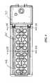
- FIG. 6is a fragmentary perspective view showing details of a lighting set proximal to a wire-passage opening of the housing.
- FIG. 7is an exploded perspective view of a source-to-board wireway with one end of a flexible duct engaged with a wire aperture of an enclosing member.
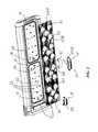
- FIG. 8is an exploded perspective view of a board-to-board wireway, including wires with male connector members.
- FIG. 9is a fragmentary perspective view showing detail of LED boards of adjacent lighting sets as used in FIG. 8 with female connector members.
- FIG. 10is a fragmentary perspective view showing each of two ends of a board-to-board flexible duct engaged with one of adjacent wire apertures of enclosing members of adjacent lighting sets shown in FIG. 8 .
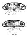
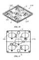
- FIG. 11is a schematic illustration of an exemplary electric circuit for a light fixture utilizing the present invention for electrical connection of two adjacent identical LED boards.
- FIG. 12is a schematic illustration of an exemplary electric circuit for a light fixture utilizing the present invention for electrical connection of two adjacent LED boards, one of which is configured for circuit termination.
- FIG. 13is a schematic illustration of an exemplary electric circuit for a light fixture utilizing the present invention for electrical connection of three LED boards, including an LED board which is configured for source-to board connection and has circuitry for connection of the other two LED boards which are adjacent and identical to one another.
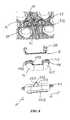
- FIG. 14is an enlarged perspective view of one example of an LED light source as an LED package including an array of eight LEDs on a submount and an asymmetric primary lens overmolded over the LED array.
- FIG. 15is an enlarged perspective view of another example of an LED light source as an LED package including an array of forty-eight LEDs on a submount and an asymmetric primary lens overmolded over the LED array.
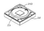
- FIG. 16is an enlarged perspective of yet another example of an LED light source as an LED package which has a single LED on a submount with a hemispheric primary lens overmolded over the LED.
- FIG. 17is an enlarged side view of the LED package of FIG. 16 .
- FIG. 18is an enlarged top view of the LED package of FIG. 16 .
- FIG. 19is an enlarged top view of another exemplary LED light source as an LED package including an array of four LEDs on a submount and a hemispheric primary lens overmolded over the LED array such that the axis of the primary lens is offset from the axis of the LED array.
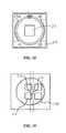
- FIG. 20is a perspective view of an alternative embodiment of an enclosing member being a single-piece optical member with a plurality of optical portions and a surrounding flange portion being made of a single polymeric material.
- FIG. 21is a top plan view of the single-piece optical member of FIG. 20 .
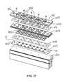
- FIG. 22is an exploded perspective view of another alternative of an enclosing member being a rigid cover member which defines a plurality of optical apertures each aligned with a respective one of a plurality of LED light sources.
- FIG. 23is a perspective view of one embodiments of an LED board with an electric circuit being printed circuit thereon and including a by-pass circuitry.
- FIGS. 1-10illustrate an exemplary embodiment of an improved LED light fixture 100 .
- LED light fixture 100includes a heat sink structure 10 and at least one LED board 20 in thermal engagement with heat sink structure 10 .
- LED board 20is shown to have an LED emitter 21 with an array of LED light sources 22 spaced along board 20 .
- FIG. 9shows LED light source 22 including an array of LEDs 23 .
- Alternative examples of LED light sourcesare shown in FIGS. 14-19 and described later in this section.
- FIGS. 8 and 9best show connectors 11 as vertical on-board connectors such as connectors manufactured by Molex Incorporated under its trademark MicroFit.
- connectors 11include a female member 11 A on LED board 20 and a male member 11 B secured to wiring 12 .
- Such connectorsprovide a desirable range of power distribution and are configured and dimensioned to require a minimal footprint area on the LED board.
- Such connectorsaccommodate a plurality of circuits, some examples of which are schematically shown in FIGS. 11-13 described further in this section.
- FIGS. 2 , 3 and 9show a gasket 14 positioned around the perimeter of LED boards 20 for sandwiching between enclosing member 30 and heat sink 10 to environmentally seal interior space 13 .
- Enclosing member 30defines a wiring aperture 31 therethrough. As best seen in FIGS. 6 and 8 , wiring aperture 31 is in alignment with on-board connector 11 for passing wires 12 through enclosure member 30 into environmentally-sealed interior space 13 from the outside which is open to environmental elements.
- FIGS. 6-8 and 10best show an exterior wireway structure 40 including a one-piece flexible duct 41 which has an end portion 42 engaged with wiring aperture 31 and which forms a channel 43 for wires 12 to on-board connector 11 , as best seen in FIGS. 3A and 3B .
- FIGS. 3 , 7 and 10show end portion 42 of duct 41 in sealing engagement with wiring aperture 31 .
- end portion 42 of flexible duct 41has an outward lip 44 defining a groove 45 which receives edge 32 of wiring aperture 31 thereby forming a seal thereabout.
- Enclosing member 30is shown as a rigid optical member 33 which has an optical portion 34 and a flange portion 35 about optical portion 34 .
- FIGS. 1-3show one exemplary embodiment of enclosing member 30 A as optical member 33 A which includes a plurality of optical portions 34 .
- Each optical portion 34corresponds to and over one of LED light sources 22 of LED emitter 21 .
- optical member 33 Ahas a plurality of optical portion 34 A formed of a first polymeric material and flange portion 35 A of a second polymeric material.
- the second polymeric material of flange portion 35 Aoverlaps with and is molded onto to the first polymeric material lens of optical portions 34 A.
- Flange portion 35 Aforms wiring aperture 31 A therethrough.
- FIGS. 20 and 21show an alternative embodiment of enclosing member 30 B as a single-piece optical member 33 B which includes a plurality of optical portions 34 B surrounded by a flange portion 35 B.
- Single-piece optical member 33 Bmay be made of a single polymeric material.
- FIG. 22shows yet another alternative embodiment of the present invention.
- Such embodimentincludes an enclosing member 30 C which is a rigid cover member 301 which defines a plurality of optical apertures 302 each aligned with a respective one of a plurality of lenses 303 shown as separate and discrete pieces, but persons skilled in the art will appreciate that lenses 303 can be formed together as a single piece.
- Each lens member 303is aligned over a corresponding one of LED light sources 22 C.
- FIG. 22shows rigid cover member 301 forming wiring apertures 31 C for engagement with end portion 42 of flexible duct 41 .
- FIG. 22also illustrates a gasket member 304 in the shape of a layer which forms a plurality of openings each aligned with a corresponding one of LED light sources 22 C. Gasket member 304 is sandwiched between cover member 301 and LED board 20 C. FIG. 22 further illustrates a shield member 24 , in the form of a layer, positioned under cover member 301 .
- a safety layer 306is positioned preferably immediately over LED light sources 22 C and includes a plurality of openings each sized to receive the corresponding one of light sources 22 C.
- Safety layer 306is for enclosure of electrical elements on LED board 20 C and includes a plurality of openings each sized to permit light from the corresponding one of light sources 22 C and also to prevent finger-contact of electrical elements on the mounting board when the light-transmission portion is not present.
- Safety barrier 306may be made of an acceptable material which satisfies applicable specifications related to material behavior such as hot-wire ignition, horizontal burning, and high-current arcing resistance, all of which are set forth in relevant UL standards.
- each of the layers of the illustrated embodimentdefines a wiring aperture aligned with and over on-board connector 11 disposed on LED board 20 C.
- FIGS. 1-8show wireway structure 40 including a single-piece rigid cover 50 secured with respect to enclosing member 30 and enclosing flexible duct 41 .
- rigid cover 50includes an attaching portion 51 which detachably secures rigid cover 50 to enclosing member 30 .
- FIGS. 7 and 8show attaching portion 51 including a resilient tab 52 which terminates with a hook 53 positioned and configured for snap-engagement with enclosing member 30 .
- enclosing member 30has an edge 36 which is configured for snap engagement by hook 53 of rigid cover 50 .
- FIGS. 1-8show wireway structure 40 including a single-piece rigid cover 50 secured with respect to enclosing member 30 and enclosing flexible duct 41 .
- rigid cover 50includes an attaching portion 51 which detachably secures rigid cover 50 to enclosing member 30 .
- FIGS. 7 and 8show attaching portion 51 including a resilient tab 52 which terminates with a hook 53 positioned and configured for snap
- FIGS. 3 , 3 A and 3 Bshow fastener 15 extend into a closed-end fastener receptor 37 formed in enclosing member 30 .
- FIGS. 1-4show LED light fixture 100 including a housing 70 with a wire-passage opening 71 through which wires 12 extend to on-board connector 11 . It is seen in FIG. 3 that housing 70 has a chamber 72 with wire-passage opening 71 from chamber 72 . It is also seen in FIG. 3 that chamber 72 encloses LED drivers 16 of electronic LED power circuitry.
- FIGS. 3A and 7illustrate one-piece flexible duct 411 as a source-to-board duct which has a second end 422 in engagement with wire-passage opening 71 of housing 70 such that wires 12 from chamber 72 pass though duct 411 to on-board connector 111 which is positioned adjacent to wire-passage opening 71 .
- FIGS. 1-4best illustrate LED light fixture 100 including a pair of lighting sets 731 and 732 adjacent to one another. It is best shown in FIGS. 2 and 3 that each of lighting sets 731 and 732 includes one enclosing member 30 and its corresponding LED board 20 .
- FIGS. 1-3show that lighting set 731 is proximal to wire-passage opening 71 of housing 70 and that source-to-board duct 411 extends between wire-passage opening 71 of housing 70 and proximal lighting set 731 .
- FIGS. 1-3 and 8 - 10show that each adjacent pair of the lighting sets 731 and 732 includes a board-to-board on-board connector 112 for each lighting set of such pair.
- FIG. 9best shows board-to-board on-board connectors 112 are proximal to one another.
- Each enclosing member 30 of adjacent lighting sets 731 and 732define a board-to-board wiring aperture 312 which is positioned over the corresponding board-to-board on-board connector 112 .
- FIGS. 8 and 10best show a board-to-board flexible duct 412 which forms a channel 432 for passing wires 12 between board-to-board on-board connectors 112 of adjacent pair of lighting sets 731 and 732 . As seen in FIG.
- board-to-board flexible duct 412has two end portions 422 each in engagement with one of adjacent board-to-board wiring apertures 312 .
- Each end portion 422 of board-to-board flexible duct 412has an outward lip 442 which defines a groove 452 receiving edge 32 of corresponding board-to-board wiring aperture 312 such that flexible duct 412 forms a seal about aperture 312 .
- FIGS. 3A and 8also show that wireway structure 40 includes a single-piece board-to-board rigid cover 502 which encloses board-to-board flexible duct 412 and is secured with respect to optical members 33 of the adjacent pair of lighting sets 731 and 732 .
- Resilient tab 522 of attaching portion 512is configured such that hook 532 is positioned and configured for simultaneous snap-engagement with edges 32 of optical members 33 of adjacent lighting sets 731 and 732 . It is further seen in FIGS.
- board-to-board rigid cover 502is further secured with respect to each of optical members 33 by fasteners 15 each of which extends through a hole in respective outward tab 54 of board-to-board rigid cover 502 into closed-end fastener receptor 37 of corresponding optical members 33 .
- FIGS. 14-19show light source 22 including at least one light-emitting diode (LED) 23 .
- Light source 22may be a light emitter in the form of an LED package which has a primary lens 24 over the at least one LED 23 .
- optical portion 34is a secondary lens 17 placed over primary lens 24 .
- Light emitter 21may be of the type illustrated in FIGS. 16-18 which show an LED package with single LED 23 on a submount 26 and hemispheric primary lens 24 D coaxially overmolded on submount 26 over LED 23 .
- FIGS. 14 and 15illustrate exemplary LED packages each including an array of LEDs 23 on an LED-populated area 25 which has an aspect ratio greater than 1, and primary lens 24 being overmolded on a submount 26 over LED-populated area 25 .
- the arraymay include LEDs 23 emitting different-wavelength light of different colors such as including red LEDs along with light green or other colors to achieve natural white light.
- Light emitters of the type as LED packages shown in FIGS. 14 and 15are described in detail in application Ser. No. 13/441,558, filed on Apr. 6, 2012, and in application Ser. No. 13/441,620, filed on Apr. 6, 2012. The contents of both applications are incorporated herein by reference in their entirety.
- FIGS. 14 , 15 and 19illustrate versions of LED light emitter 21 configured to refract LED-emitted light in a forward direction 1 (i.e., toward front 1 ).
- the LED arraydefines an emitter axis.
- FIGS. 14 and 15illustrate primary lens 24 A configured to refract LED-emitted light forward.
- FIG. 19shows hemispheric primary lens 24 C having a centerline 240 offset from the emitter axis. It should be understood that for higher efficiency, LED emitter 21 may have a primary lens having both its centerline offset from the emitter axis and also being shaped for refraction of LED-emitted light toward preferential side 1 .
- primary lens 24 Ais shown as asymmetric.
- FIGS. 11-13illustrate examples of electrical circuitry utilizing the present invention.
- FIG. 11shows an example of electrical connection of two adjacent identical LED boards 20 .
- Each of LED boards 20are shown to include a bypass circuit 27 which extends from source-to-board on-board connector 111 to board-to-board on-board connector 112 such that adjacent LED boards 20 are electrically connected in parallel.
- FIG. 23illustrates an example of LED board 20 including a working circuit 28 connecting LED light sources 22 on board 20 to connection points 114 with source-to-board on-board connector 111 .
- LED board 20is shown to also include bypass circuit lines 27 which extend from connection points 115 for source-to-board on-board connector 111 in parallel with respect to circuitry 28 .
- bypass circuit lines 27extend to board-to-board on-board connector 112 to provide electrical connection to the adjacent LED board.
- source-to-board on-board connector 111is configured for connection with two pairs of wires received from a power source—one pair being connected to working circuit 28 and the second pair being connected to bypass circuit 27 .
- FIG. 12shows another example of electrical circuitry for parallel connection of two adjacent LED boards.
- LED board 20which is proximal to fixture housing 70 , includes a bypass circuit 27 .
- FIG. 12shows adjacent LED board 20 A being configured for circuit termination.
- FIG. 13schematically illustrates parallel connection of three LED boards, including an LED board 201 which is proximal to fixture housing 70 and includes two bypass circuit lines 27 extending from source-to-board on-board connector 113 .
- source-to-board on-board connector 113is configured for connection with three pairs of wires received from a power source—one pair being connected to working circuit 28 on board 201 , each of the other two pairs of wires being connected to one of bypass circuits 27 on board 201 and extending to board-to-board on-board connector 112 on board 201 .
- FIG. 13shows first and second distal LED boards 20 being identical, but with bypass circuit 27 printed on the second distal LED board 20 being left without any wire connection. Such combination is convenient in that one type of LED board is used. It should be understood that the second distal LED board 20 can be configured for circuit termination as LED board 20 A in FIG. 12 .
- enclosing member 30has a capped wiring aperture 31 A aligned over a connector or a location for a connector at an end of LED board 20 which is most distal from housing 70 .
- capped wiring aperture 31 Amay be opened if further wiring connection is required.
- enclosing member 30may be continuously closed without any apertures.
Landscapes
- Engineering & Computer Science (AREA)
- General Engineering & Computer Science (AREA)
- Physics & Mathematics (AREA)
- Microelectronics & Electronic Packaging (AREA)
- Optics & Photonics (AREA)
- Non-Portable Lighting Devices Or Systems Thereof (AREA)
- Arrangement Of Elements, Cooling, Sealing, Or The Like Of Lighting Devices (AREA)
- Fastening Of Light Sources Or Lamp Holders (AREA)
Abstract
Description
Claims (42)
Priority Applications (1)
| Application Number | Priority Date | Filing Date | Title |
|---|---|---|---|
| US14/070,116US9273833B2 (en) | 2013-11-01 | 2013-11-01 | LED light fixtures with arrangement for electrical connection |
Applications Claiming Priority (1)
| Application Number | Priority Date | Filing Date | Title |
|---|---|---|---|
| US14/070,116US9273833B2 (en) | 2013-11-01 | 2013-11-01 | LED light fixtures with arrangement for electrical connection |
Publications (2)
| Publication Number | Publication Date |
|---|---|
| US20150124449A1 US20150124449A1 (en) | 2015-05-07 |
| US9273833B2true US9273833B2 (en) | 2016-03-01 |
Family
ID=53006899
Family Applications (1)
| Application Number | Title | Priority Date | Filing Date |
|---|---|---|---|
| US14/070,116Active2034-05-05US9273833B2 (en) | 2013-11-01 | 2013-11-01 | LED light fixtures with arrangement for electrical connection |
Country Status (1)
| Country | Link |
|---|---|
| US (1) | US9273833B2 (en) |
Families Citing this family (16)
| Publication number | Priority date | Publication date | Assignee | Title |
|---|---|---|---|---|
| KR20150137458A (en)* | 2014-05-29 | 2015-12-09 | 주식회사 포스코엘이디 | Optical semiconductor illuminating apparatus |
| US9470394B2 (en)* | 2014-11-24 | 2016-10-18 | Cree, Inc. | LED light fixture including optical member with in-situ-formed gasket and method of manufacture |
| US10253956B2 (en) | 2015-08-26 | 2019-04-09 | Abl Ip Holding Llc | LED luminaire with mounting structure for LED circuit board |
| US10816165B2 (en)* | 2015-11-19 | 2020-10-27 | Lsi Industries, Inc. | LED luminaire assembly |
| USD800948S1 (en)* | 2015-12-01 | 2017-10-24 | MaxLite, Inc. | Modular LED light housing for rigid surface mounting |
| USD800947S1 (en)* | 2015-12-01 | 2017-10-24 | MaxLite, Inc. | Modular LED light housing with a slip fitter mounting |
| USD800949S1 (en)* | 2015-12-01 | 2017-10-24 | MaxLite, Inc. | Modular LED light housing with an adjustable surface mounting |
| USD800945S1 (en)* | 2015-12-01 | 2017-10-24 | MaxLite, Inc. | Modular LED light housing with a trunnion mounting |
| USD800946S1 (en)* | 2015-12-01 | 2017-10-24 | MaxLite, Inc. | Modular LED light housing for tennon mounting |
| USD800951S1 (en)* | 2015-12-01 | 2017-10-24 | MaxLite, Inc. | Modular LED light housing for wall mounting |
| USD800950S1 (en)* | 2015-12-01 | 2017-10-24 | MaxLite, Inc. | Modular LED light housing for pole mounting |
| USD792010S1 (en)* | 2016-03-01 | 2017-07-11 | Neptun Light, Inc. | Light fixture |
| USD792011S1 (en)* | 2016-05-10 | 2017-07-11 | Neptun Light, Inc. | Light fixture |
| US10190755B2 (en) | 2016-11-15 | 2019-01-29 | Abl Ip Holding Llc | LED board retention |
| US10251279B1 (en) | 2018-01-04 | 2019-04-02 | Abl Ip Holding Llc | Printed circuit board mounting with tabs |
| CN114321743A (en)* | 2021-12-21 | 2022-04-12 | 桂林海威科技股份有限公司 | Multi-module LED lamp |
Citations (68)
| Publication number | Priority date | Publication date | Assignee | Title |
|---|---|---|---|---|
| US3860829A (en) | 1973-08-10 | 1975-01-14 | Keene Corp | Fluorescent fixture auxiliary light |
| US4071749A (en) | 1976-07-22 | 1978-01-31 | Tork, Inc. | Self-contained maintenance-free emergency lighting |
| US4156891A (en) | 1976-09-27 | 1979-05-29 | Roche Thomas F | Explosion-proof emergency light |
| US4254453A (en) | 1978-08-25 | 1981-03-03 | General Instrument Corporation | Alpha-numeric display array and method of manufacture |
| US5004953A (en) | 1989-06-30 | 1991-04-02 | The Bodine Company | Emergency lighting ballast for compact fluorescent lamps with integral starters |
| US5303124A (en) | 1993-07-21 | 1994-04-12 | Avi Wrobel | Self-energizing LED lamp |
| US5633564A (en) | 1995-06-01 | 1997-05-27 | Edwards; M. Larry | Modular uninterruptible lighting system |
| US5676455A (en) | 1995-11-01 | 1997-10-14 | Spi Lighting, Inc. | Wall mountable lighting fixture |
| WO1998033007A1 (en) | 1997-01-23 | 1998-07-30 | Koninklijke Philips Electronics N.V. | Luminaire |
| US5890794A (en) | 1996-04-03 | 1999-04-06 | Abtahi; Homayoon | Lighting units |
| US5909062A (en) | 1998-03-10 | 1999-06-01 | Krietzman; Mark Howard | Secondary power supply for use with handheld illumination devices |
| WO1999057945A1 (en) | 1998-05-04 | 1999-11-11 | Fiber Optic Designs, Inc. | A lamp employing a monolithic led device |
| US5988829A (en) | 1997-07-28 | 1999-11-23 | Nsi Enterprises, Inc. | Direct/indirect lighting fixtures |
| US6045232A (en) | 1998-02-16 | 2000-04-04 | Buckmaster; Clifford Thoren | Apparatus for providing emergency and night lighting |
| WO2002016826A1 (en) | 2000-08-24 | 2002-02-28 | Simon Grant Rozenberg | Improvements in lamps, luminaires and lighting systems |
| US20020113244A1 (en) | 2001-02-22 | 2002-08-22 | Barnett Thomas J. | High power LED |
| US6522263B2 (en) | 1991-10-09 | 2003-02-18 | R.D. Jones, Right Of Way, Inc. | Traffic control system and kit |
| US20030048608A1 (en) | 2001-09-10 | 2003-03-13 | Intel Corporation | Radial folded fin heat sinks and methods of making and using same |
| US6565238B1 (en) | 2000-06-23 | 2003-05-20 | H. E. Williams, Inc. | Fluorescent light fixture with lateral ballast |
| WO2003044870A1 (en) | 2001-11-22 | 2003-05-30 | Mireille Georges | Light-emitting diode illuminating optical device |
| WO2003089841A1 (en) | 2002-04-20 | 2003-10-30 | Ewington Christopher James | Lighting module |
| US6648496B1 (en) | 2000-06-27 | 2003-11-18 | General Electric Company | Nightlight with light emitting diode source |
| US20040036629A1 (en) | 1998-07-13 | 2004-02-26 | Blinkerstop, Llc. | Enhanced visibility traffic signal |
| US20040114356A1 (en) | 2001-12-10 | 2004-06-17 | Robert Galli | Waterproof flashlight assembly |
| EP1431653A2 (en) | 2002-12-19 | 2004-06-23 | Toshiji Kishimura | Light source for white color LED lighting and white color led lighting device |
| US6758580B1 (en) | 2001-06-01 | 2004-07-06 | Neal R. Verfuerth | Fluorescent hanging light fixture |
| US6784357B1 (en) | 2002-02-07 | 2004-08-31 | Chao Hsiang Wang | Solar energy-operated street-lamp system |
| US6784351B2 (en) | 2001-06-29 | 2004-08-31 | Ball Horticultural Company | Targetes erecta marigolds with altered carotenoid compositions and ratios |
| US6815724B2 (en) | 2002-05-29 | 2004-11-09 | Optolum, Inc. | Light emitting diode light source |
| US20040257006A1 (en) | 2002-07-23 | 2004-12-23 | Randy Beeman | Variable color landscape lighting |
| JP2005150003A (en) | 2003-11-19 | 2005-06-09 | Toshiba Lighting & Technology Corp | Explosion-proof lighting equipment and explosion-proof lighting system |
| US20050174762A1 (en) | 2004-02-09 | 2005-08-11 | Fogerlie Sivert G. | Light box having a solar panel cover |
| US6942360B2 (en) | 2003-10-01 | 2005-09-13 | Enertron, Inc. | Methods and apparatus for an LED light engine |
| US6957905B1 (en) | 2001-10-03 | 2005-10-25 | Led Pipe, Inc. | Solid state light source |
| US6984061B1 (en) | 2003-03-05 | 2006-01-10 | Soderberg Manufacturing Co., Inc. | Covert infrared landing light |
| US7036961B2 (en) | 2002-07-01 | 2006-05-02 | Hubbell Incorporated | Recessed lighting fixture with battery backup |
| WO2006060905A1 (en) | 2004-12-07 | 2006-06-15 | Elumen Lighting Networks Inc. | Assembly of light emitting diodes for lighting applications |
| US7090370B2 (en) | 2001-06-08 | 2006-08-15 | Advanced Leds Limited | Exterior luminaire |
| US7114830B2 (en) | 2002-07-17 | 2006-10-03 | Plastic Inventions And Patents, Inc. | LED replacement for fluorescent lighting |
| US20060250803A1 (en) | 2005-05-04 | 2006-11-09 | Chia-Yi Chen | Street light with heat dispensing device |
| US7153004B2 (en) | 2002-12-10 | 2006-12-26 | Galli Robert D | Flashlight housing |
| US7178941B2 (en) | 2003-05-05 | 2007-02-20 | Color Kinetics Incorporated | Lighting methods and systems |
| EP1760393A1 (en) | 2005-08-30 | 2007-03-07 | Nuriplan Co., Ltd. | LED module and line type LED illumination lamp |
| US7199529B2 (en) | 2002-03-22 | 2007-04-03 | Gdrc Limited | Inductive lighting system with back-up battery |
| US20070086196A1 (en) | 2005-10-18 | 2007-04-19 | National Tsing Hua University | Heat dissipation devices for and LED lamp set |
| US20070115666A1 (en) | 2004-09-23 | 2007-05-24 | Thomas James G | Illumination system |
| US7234844B2 (en) | 2002-12-11 | 2007-06-26 | Charles Bolta | Light emitting diode (L.E.D.) lighting fixtures with emergency back-up and scotopic enhancement |
| US7244042B1 (en) | 2006-10-21 | 2007-07-17 | Roger Bieberdorf | Airport light system |
| US7267459B2 (en) | 2004-01-28 | 2007-09-11 | Tir Systems Ltd. | Sealed housing unit for lighting system |
| USD551379S1 (en) | 2005-10-14 | 2007-09-18 | Lighting Science Group Corporation | Low-bay light fixture |
| US7278761B2 (en) | 2005-10-06 | 2007-10-09 | Thermalking Technology International Co. | Heat dissipating pole illumination device |
| US7303301B2 (en) | 2005-11-01 | 2007-12-04 | Nexxus Lighting, Inc. | Submersible LED light fixture |
| CN101093073A (en) | 2007-07-20 | 2007-12-26 | 李旭亮 | Section bar |
| CN101101103A (en) | 2007-07-20 | 2008-01-09 | 李旭亮 | LED road lamp |
| CN101101104A (en) | 2007-07-20 | 2008-01-09 | 李旭亮 | LED road lamp body |
| CN101101106A (en) | 2007-07-24 | 2008-01-09 | 李旭亮 | LED road lamp body |
| CN101101107A (en) | 2007-07-24 | 2008-01-09 | 李旭亮 | LED road lamp |
| CN101101102A (en) | 2007-07-20 | 2008-01-09 | 李旭亮 | LED road lamp |
| CN101105278A (en) | 2007-07-31 | 2008-01-16 | 李旭亮 | Environment-friendly type LED road lamp |
| CN101105268A (en) | 2007-07-31 | 2008-01-16 | 李旭亮 | LED road lamp and LED road lamp radiation area expansion method |
| US20080037239A1 (en) | 2006-06-30 | 2008-02-14 | James Thomas | Elongated led lighting fixture |
| EP1906081A1 (en) | 2006-09-30 | 2008-04-02 | Ruud Lighting, Inc. | LED floodlight fixture |
| US20080080162A1 (en)* | 2006-09-30 | 2008-04-03 | Ruud Lighting, Inc. | LED Light Fixture with Uninterruptible Power Supply |
| US20080080189A1 (en) | 2006-09-29 | 2008-04-03 | Pei-Choa Wang | LED Illumination Apparatus |
| US7503669B2 (en) | 2000-05-08 | 2009-03-17 | Farlight, Llc | Portable luminaire |
| US7566147B2 (en) | 2007-05-04 | 2009-07-28 | Ruud Lighting, Inc. | Multi-LED light fixture with secure arrangement for LED-array wiring |
| US20090268477A1 (en) | 2008-04-25 | 2009-10-29 | Fu Zhun Precision Industry (Shen Zhen) Co., Ltd. | Led lamp |
| US8092049B2 (en) | 2008-04-04 | 2012-01-10 | Ruud Lighting, Inc. | LED light fixture |
- 2013
- 2013-11-01USUS14/070,116patent/US9273833B2/enactiveActive
Patent Citations (77)
| Publication number | Priority date | Publication date | Assignee | Title |
|---|---|---|---|---|
| US3860829A (en) | 1973-08-10 | 1975-01-14 | Keene Corp | Fluorescent fixture auxiliary light |
| US4071749A (en) | 1976-07-22 | 1978-01-31 | Tork, Inc. | Self-contained maintenance-free emergency lighting |
| US4156891A (en) | 1976-09-27 | 1979-05-29 | Roche Thomas F | Explosion-proof emergency light |
| US4254453A (en) | 1978-08-25 | 1981-03-03 | General Instrument Corporation | Alpha-numeric display array and method of manufacture |
| US5004953A (en) | 1989-06-30 | 1991-04-02 | The Bodine Company | Emergency lighting ballast for compact fluorescent lamps with integral starters |
| US6522263B2 (en) | 1991-10-09 | 2003-02-18 | R.D. Jones, Right Of Way, Inc. | Traffic control system and kit |
| US5303124A (en) | 1993-07-21 | 1994-04-12 | Avi Wrobel | Self-energizing LED lamp |
| US5633564A (en) | 1995-06-01 | 1997-05-27 | Edwards; M. Larry | Modular uninterruptible lighting system |
| US5676455A (en) | 1995-11-01 | 1997-10-14 | Spi Lighting, Inc. | Wall mountable lighting fixture |
| US5890794A (en) | 1996-04-03 | 1999-04-06 | Abtahi; Homayoon | Lighting units |
| WO1998033007A1 (en) | 1997-01-23 | 1998-07-30 | Koninklijke Philips Electronics N.V. | Luminaire |
| US5988829A (en) | 1997-07-28 | 1999-11-23 | Nsi Enterprises, Inc. | Direct/indirect lighting fixtures |
| US6045232A (en) | 1998-02-16 | 2000-04-04 | Buckmaster; Clifford Thoren | Apparatus for providing emergency and night lighting |
| US5909062A (en) | 1998-03-10 | 1999-06-01 | Krietzman; Mark Howard | Secondary power supply for use with handheld illumination devices |
| WO1999057945A1 (en) | 1998-05-04 | 1999-11-11 | Fiber Optic Designs, Inc. | A lamp employing a monolithic led device |
| US20040036629A1 (en) | 1998-07-13 | 2004-02-26 | Blinkerstop, Llc. | Enhanced visibility traffic signal |
| US7503669B2 (en) | 2000-05-08 | 2009-03-17 | Farlight, Llc | Portable luminaire |
| US6565238B1 (en) | 2000-06-23 | 2003-05-20 | H. E. Williams, Inc. | Fluorescent light fixture with lateral ballast |
| US6648496B1 (en) | 2000-06-27 | 2003-11-18 | General Electric Company | Nightlight with light emitting diode source |
| WO2002016826A1 (en) | 2000-08-24 | 2002-02-28 | Simon Grant Rozenberg | Improvements in lamps, luminaires and lighting systems |
| US20020113244A1 (en) | 2001-02-22 | 2002-08-22 | Barnett Thomas J. | High power LED |
| US6758580B1 (en) | 2001-06-01 | 2004-07-06 | Neal R. Verfuerth | Fluorescent hanging light fixture |
| US7090370B2 (en) | 2001-06-08 | 2006-08-15 | Advanced Leds Limited | Exterior luminaire |
| US6784351B2 (en) | 2001-06-29 | 2004-08-31 | Ball Horticultural Company | Targetes erecta marigolds with altered carotenoid compositions and ratios |
| US20030048608A1 (en) | 2001-09-10 | 2003-03-13 | Intel Corporation | Radial folded fin heat sinks and methods of making and using same |
| US6657862B2 (en) | 2001-09-10 | 2003-12-02 | Intel Corporation | Radial folded fin heat sinks and methods of making and using same |
| US6957905B1 (en) | 2001-10-03 | 2005-10-25 | Led Pipe, Inc. | Solid state light source |
| WO2003044870A1 (en) | 2001-11-22 | 2003-05-30 | Mireille Georges | Light-emitting diode illuminating optical device |
| US20040114356A1 (en) | 2001-12-10 | 2004-06-17 | Robert Galli | Waterproof flashlight assembly |
| US6784357B1 (en) | 2002-02-07 | 2004-08-31 | Chao Hsiang Wang | Solar energy-operated street-lamp system |
| US7199529B2 (en) | 2002-03-22 | 2007-04-03 | Gdrc Limited | Inductive lighting system with back-up battery |
| WO2003089841A1 (en) | 2002-04-20 | 2003-10-30 | Ewington Christopher James | Lighting module |
| US20050128752A1 (en) | 2002-04-20 | 2005-06-16 | Ewington Christopher D. | Lighting module |
| US6815724B2 (en) | 2002-05-29 | 2004-11-09 | Optolum, Inc. | Light emitting diode light source |
| US7036961B2 (en) | 2002-07-01 | 2006-05-02 | Hubbell Incorporated | Recessed lighting fixture with battery backup |
| US7114830B2 (en) | 2002-07-17 | 2006-10-03 | Plastic Inventions And Patents, Inc. | LED replacement for fluorescent lighting |
| US20040257006A1 (en) | 2002-07-23 | 2004-12-23 | Randy Beeman | Variable color landscape lighting |
| US7153004B2 (en) | 2002-12-10 | 2006-12-26 | Galli Robert D | Flashlight housing |
| US7234844B2 (en) | 2002-12-11 | 2007-06-26 | Charles Bolta | Light emitting diode (L.E.D.) lighting fixtures with emergency back-up and scotopic enhancement |
| US6942361B1 (en) | 2002-12-19 | 2005-09-13 | Toshiji Kishimura | Light source for white color LED lighting and white color LED lighting device |
| EP1431653A2 (en) | 2002-12-19 | 2004-06-23 | Toshiji Kishimura | Light source for white color LED lighting and white color led lighting device |
| US6984061B1 (en) | 2003-03-05 | 2006-01-10 | Soderberg Manufacturing Co., Inc. | Covert infrared landing light |
| US7178941B2 (en) | 2003-05-05 | 2007-02-20 | Color Kinetics Incorporated | Lighting methods and systems |
| US6942360B2 (en) | 2003-10-01 | 2005-09-13 | Enertron, Inc. | Methods and apparatus for an LED light engine |
| JP2005150003A (en) | 2003-11-19 | 2005-06-09 | Toshiba Lighting & Technology Corp | Explosion-proof lighting equipment and explosion-proof lighting system |
| US7267459B2 (en) | 2004-01-28 | 2007-09-11 | Tir Systems Ltd. | Sealed housing unit for lighting system |
| US20050174762A1 (en) | 2004-02-09 | 2005-08-11 | Fogerlie Sivert G. | Light box having a solar panel cover |
| US20070115666A1 (en) | 2004-09-23 | 2007-05-24 | Thomas James G | Illumination system |
| WO2006060905A1 (en) | 2004-12-07 | 2006-06-15 | Elumen Lighting Networks Inc. | Assembly of light emitting diodes for lighting applications |
| US20060250803A1 (en) | 2005-05-04 | 2006-11-09 | Chia-Yi Chen | Street light with heat dispensing device |
| EP1760393A1 (en) | 2005-08-30 | 2007-03-07 | Nuriplan Co., Ltd. | LED module and line type LED illumination lamp |
| US7278761B2 (en) | 2005-10-06 | 2007-10-09 | Thermalking Technology International Co. | Heat dissipating pole illumination device |
| USD551379S1 (en) | 2005-10-14 | 2007-09-18 | Lighting Science Group Corporation | Low-bay light fixture |
| US20070086196A1 (en) | 2005-10-18 | 2007-04-19 | National Tsing Hua University | Heat dissipation devices for and LED lamp set |
| US7303301B2 (en) | 2005-11-01 | 2007-12-04 | Nexxus Lighting, Inc. | Submersible LED light fixture |
| US20080037239A1 (en) | 2006-06-30 | 2008-02-14 | James Thomas | Elongated led lighting fixture |
| US7513639B2 (en) | 2006-09-29 | 2009-04-07 | Pyroswift Holding Co., Limited | LED illumination apparatus |
| US20080080189A1 (en) | 2006-09-29 | 2008-04-03 | Pei-Choa Wang | LED Illumination Apparatus |
| US8425071B2 (en) | 2006-09-30 | 2013-04-23 | Cree, Inc. | LED lighting fixture |
| US7771087B2 (en) | 2006-09-30 | 2010-08-10 | Ruud Lighting, Inc. | LED light fixture with uninterruptible power supply |
| US20080080162A1 (en)* | 2006-09-30 | 2008-04-03 | Ruud Lighting, Inc. | LED Light Fixture with Uninterruptible Power Supply |
| US20080080196A1 (en) | 2006-09-30 | 2008-04-03 | Ruud Lighting, Inc. | LED Floodlight Fixture |
| EP1906081A1 (en) | 2006-09-30 | 2008-04-02 | Ruud Lighting, Inc. | LED floodlight fixture |
| US7244042B1 (en) | 2006-10-21 | 2007-07-17 | Roger Bieberdorf | Airport light system |
| US7566147B2 (en) | 2007-05-04 | 2009-07-28 | Ruud Lighting, Inc. | Multi-LED light fixture with secure arrangement for LED-array wiring |
| CN101101104A (en) | 2007-07-20 | 2008-01-09 | 李旭亮 | LED road lamp body |
| CN101093073A (en) | 2007-07-20 | 2007-12-26 | 李旭亮 | Section bar |
| CN101101102A (en) | 2007-07-20 | 2008-01-09 | 李旭亮 | LED road lamp |
| CN101101103A (en) | 2007-07-20 | 2008-01-09 | 李旭亮 | LED road lamp |
| CN101101107A (en) | 2007-07-24 | 2008-01-09 | 李旭亮 | LED road lamp |
| CN101101106A (en) | 2007-07-24 | 2008-01-09 | 李旭亮 | LED road lamp body |
| CN101105268A (en) | 2007-07-31 | 2008-01-16 | 李旭亮 | LED road lamp and LED road lamp radiation area expansion method |
| CN101105278A (en) | 2007-07-31 | 2008-01-16 | 李旭亮 | Environment-friendly type LED road lamp |
| US8092049B2 (en) | 2008-04-04 | 2012-01-10 | Ruud Lighting, Inc. | LED light fixture |
| US8313222B2 (en) | 2008-04-04 | 2012-11-20 | Ruud Lighting, Inc. | LED light fixture |
| US8622584B2 (en) | 2008-04-04 | 2014-01-07 | Cree, Inc. | LED light fixture |
| US20090268477A1 (en) | 2008-04-25 | 2009-10-29 | Fu Zhun Precision Industry (Shen Zhen) Co., Ltd. | Led lamp |
Non-Patent Citations (7)
| Title |
|---|
| "LED Light Sources" product description. Aavid Thermalloy. Date: Copyright 2006. |
| Lithonia Lighting. Industrial Accessories-Wireguards Accessories (ACCI). Date: 1999. |
| Lithonia Lighting. Installation Instructions-Single and Twin Mounting Bar (RJ5210060). Date: Jun. 1999. |
| Molex. Specification sheet for Part No. 43025-0400. 2 pages. Date: Sep. 3, 2013. |
| Molex. Specification sheet for Part No. 43045-0418. 2 pages. Date: Sep. 3, 2013. |
| Stanley Electric Co., Ltd. "Stanley LED for Street Light", brochure. Date: Aug. 2006. |
| W.A.C. Lighting. W.A.C. Lighting Catalog (e.g., cover, pp. 3, 5-6, 15, 23, 34). Date: 1998. |
Also Published As
| Publication number | Publication date |
|---|---|
| US20150124449A1 (en) | 2015-05-07 |
Similar Documents
| Publication | Publication Date | Title |
|---|---|---|
| US9273833B2 (en) | LED light fixtures with arrangement for electrical connection | |
| US7926977B2 (en) | LED lighting system for a cabinet sign | |
| US9423116B2 (en) | LED lamp and modular lighting system | |
| US20130107526A1 (en) | Led mounting circuit board, belt-like flexible led light and led illuminating device using the same | |
| US9179511B2 (en) | Light-emitting device, and light source for lighting and lighting apparatus using the same | |
| US7976335B2 (en) | LED connector assembly with heat sink | |
| US20170227177A1 (en) | Led lamp with internal reflector | |
| US11708966B2 (en) | Strip lighting system for direct input of high voltage driving power | |
| CN102132082B (en) | Lighting device | |
| US9927100B2 (en) | LED lamp with LED board brace | |
| US10920963B2 (en) | Light fixture having fixed angular position and lamp module for light fixtures | |
| US10048433B2 (en) | Flat panel lighting apparatus | |
| CN204403966U (en) | Ligthing paraphernalia and secondary light source unit | |
| US10830429B2 (en) | Luminaire housing | |
| US20210293397A1 (en) | Perimeter luminaire | |
| US10627081B1 (en) | LED lighting module including a rigid carrier component | |
| CN203323027U (en) | Luminous module | |
| CN204459826U (en) | Light emitting module and lighting device | |
| KR20130127166A (en) | Lighting equipment | |
| US20140286007A1 (en) | Light-Emitting Module and Luminaire | |
| KR101516399B1 (en) | LED lighting lamp | |
| WO2018166292A1 (en) | Illumination device | |
| JP2016171248A (en) | Light-emitting module and illumination device |
Legal Events
| Date | Code | Title | Description |
|---|---|---|---|
| AS | Assignment | Owner name:CREE, INC., NORTH CAROLINA Free format text:ASSIGNMENT OF ASSIGNORS INTEREST;ASSIGNORS:WILCOX, KURT;BENDTSEN, ANDREW;QUELLA, DAN;REEL/FRAME:031677/0329 Effective date:20131108 | |
| STCF | Information on status: patent grant | Free format text:PATENTED CASE | |
| AS | Assignment | Owner name:IDEAL INDUSTRIES LIGHTING LLC, ILLINOIS Free format text:ASSIGNMENT OF ASSIGNORS INTEREST;ASSIGNOR:CREE, INC.;REEL/FRAME:049880/0524 Effective date:20190513 | |
| MAFP | Maintenance fee payment | Free format text:PAYMENT OF MAINTENANCE FEE, 4TH YEAR, LARGE ENTITY (ORIGINAL EVENT CODE: M1551); ENTITY STATUS OF PATENT OWNER: LARGE ENTITY Year of fee payment:4 | |
| MAFP | Maintenance fee payment | Free format text:PAYMENT OF MAINTENANCE FEE, 8TH YEAR, LARGE ENTITY (ORIGINAL EVENT CODE: M1552); ENTITY STATUS OF PATENT OWNER: LARGE ENTITY Year of fee payment:8 | |
| AS | Assignment | Owner name:FGI WORLDWIDE LLC, NEW YORK Free format text:SECURITY INTEREST;ASSIGNOR:IDEAL INDUSTRIES LIGHTING LLC;REEL/FRAME:064897/0413 Effective date:20230908 |