US9273570B2 - Methods for power generation from H2O, CO2, O2 and a carbon feed stock - Google Patents
Methods for power generation from H2O, CO2, O2 and a carbon feed stockDownload PDFInfo
- Publication number
- US9273570B2 US9273570B2US14/426,093US201314426093AUS9273570B2US 9273570 B2US9273570 B2US 9273570B2US 201314426093 AUS201314426093 AUS 201314426093AUS 9273570 B2US9273570 B2US 9273570B2
- Authority
- US
- United States
- Prior art keywords
- fluid
- working fluid
- high voltage
- voltage electric
- plasma
- Prior art date
- Legal status (The legal status is an assumption and is not a legal conclusion. Google has not performed a legal analysis and makes no representation as to the accuracy of the status listed.)
- Expired - Fee Related
Links
Images

Classifications
- F—MECHANICAL ENGINEERING; LIGHTING; HEATING; WEAPONS; BLASTING
- F01—MACHINES OR ENGINES IN GENERAL; ENGINE PLANTS IN GENERAL; STEAM ENGINES
- F01K—STEAM ENGINE PLANTS; STEAM ACCUMULATORS; ENGINE PLANTS NOT OTHERWISE PROVIDED FOR; ENGINES USING SPECIAL WORKING FLUIDS OR CYCLES
- F01K25/00—Plants or engines characterised by use of special working fluids, not otherwise provided for; Plants operating in closed cycles and not otherwise provided for
- F01K25/06—Plants or engines characterised by use of special working fluids, not otherwise provided for; Plants operating in closed cycles and not otherwise provided for using mixtures of different fluids
- B—PERFORMING OPERATIONS; TRANSPORTING
- B01—PHYSICAL OR CHEMICAL PROCESSES OR APPARATUS IN GENERAL
- B01D—SEPARATION
- B01D21/00—Separation of suspended solid particles from liquids by sedimentation
- B01D21/0009—Settling tanks making use of electricity or magnetism
- B—PERFORMING OPERATIONS; TRANSPORTING
- B01—PHYSICAL OR CHEMICAL PROCESSES OR APPARATUS IN GENERAL
- B01D—SEPARATION
- B01D21/00—Separation of suspended solid particles from liquids by sedimentation
- B01D21/01—Separation of suspended solid particles from liquids by sedimentation using flocculating agents
- B—PERFORMING OPERATIONS; TRANSPORTING
- B01—PHYSICAL OR CHEMICAL PROCESSES OR APPARATUS IN GENERAL
- B01J—CHEMICAL OR PHYSICAL PROCESSES, e.g. CATALYSIS OR COLLOID CHEMISTRY; THEIR RELEVANT APPARATUS
- B01J12/00—Chemical processes in general for reacting gaseous media with gaseous media; Apparatus specially adapted therefor
- B01J12/002—Chemical processes in general for reacting gaseous media with gaseous media; Apparatus specially adapted therefor carried out in the plasma state
- B—PERFORMING OPERATIONS; TRANSPORTING
- B01—PHYSICAL OR CHEMICAL PROCESSES OR APPARATUS IN GENERAL
- B01J—CHEMICAL OR PHYSICAL PROCESSES, e.g. CATALYSIS OR COLLOID CHEMISTRY; THEIR RELEVANT APPARATUS
- B01J19/00—Chemical, physical or physico-chemical processes in general; Their relevant apparatus
- B01J19/08—Processes employing the direct application of electric or wave energy, or particle radiation; Apparatus therefor
- B01J19/087—Processes employing the direct application of electric or wave energy, or particle radiation; Apparatus therefor employing electric or magnetic energy
- B01J19/088—Processes employing the direct application of electric or wave energy, or particle radiation; Apparatus therefor employing electric or magnetic energy giving rise to electric discharges
- B—PERFORMING OPERATIONS; TRANSPORTING
- B03—SEPARATION OF SOLID MATERIALS USING LIQUIDS OR USING PNEUMATIC TABLES OR JIGS; MAGNETIC OR ELECTROSTATIC SEPARATION OF SOLID MATERIALS FROM SOLID MATERIALS OR FLUIDS; SEPARATION BY HIGH-VOLTAGE ELECTRIC FIELDS
- B03C—MAGNETIC OR ELECTROSTATIC SEPARATION OF SOLID MATERIALS FROM SOLID MATERIALS OR FLUIDS; SEPARATION BY HIGH-VOLTAGE ELECTRIC FIELDS
- B03C3/00—Separating dispersed particles from gases or vapour, e.g. air, by electrostatic effect
- B03C3/02—Plant or installations having external electricity supply
- B03C3/025—Combinations of electrostatic separators, e.g. in parallel or in series, stacked separators or dry-wet separator combinations
- B—PERFORMING OPERATIONS; TRANSPORTING
- B03—SEPARATION OF SOLID MATERIALS USING LIQUIDS OR USING PNEUMATIC TABLES OR JIGS; MAGNETIC OR ELECTROSTATIC SEPARATION OF SOLID MATERIALS FROM SOLID MATERIALS OR FLUIDS; SEPARATION BY HIGH-VOLTAGE ELECTRIC FIELDS
- B03C—MAGNETIC OR ELECTROSTATIC SEPARATION OF SOLID MATERIALS FROM SOLID MATERIALS OR FLUIDS; SEPARATION BY HIGH-VOLTAGE ELECTRIC FIELDS
- B03C3/00—Separating dispersed particles from gases or vapour, e.g. air, by electrostatic effect
- B03C3/02—Plant or installations having external electricity supply
- B03C3/16—Plant or installations having external electricity supply wet type
- B09B3/005—
- B—PERFORMING OPERATIONS; TRANSPORTING
- B09—DISPOSAL OF SOLID WASTE; RECLAMATION OF CONTAMINATED SOIL
- B09B—DISPOSAL OF SOLID WASTE NOT OTHERWISE PROVIDED FOR
- B09B3/00—Destroying solid waste or transforming solid waste into something useful or harmless
- B09B3/20—Agglomeration, binding or encapsulation of solid waste
- B09B3/25—Agglomeration, binding or encapsulation of solid waste using mineral binders or matrix
- B09B3/29—Agglomeration, binding or encapsulation of solid waste using mineral binders or matrix involving a melting or softening step
- C—CHEMISTRY; METALLURGY
- C01—INORGANIC CHEMISTRY
- C01B—NON-METALLIC ELEMENTS; COMPOUNDS THEREOF; METALLOIDS OR COMPOUNDS THEREOF NOT COVERED BY SUBCLASS C01C
- C01B3/00—Hydrogen; Gaseous mixtures containing hydrogen; Separation of hydrogen from mixtures containing it; Purification of hydrogen
- C01B3/02—Production of hydrogen or of gaseous mixtures containing a substantial proportion of hydrogen
- C01B3/04—Production of hydrogen or of gaseous mixtures containing a substantial proportion of hydrogen by decomposition of inorganic compounds, e.g. ammonia
- C01B3/042—Decomposition of water
- C—CHEMISTRY; METALLURGY
- C01—INORGANIC CHEMISTRY
- C01B—NON-METALLIC ELEMENTS; COMPOUNDS THEREOF; METALLOIDS OR COMPOUNDS THEREOF NOT COVERED BY SUBCLASS C01C
- C01B3/00—Hydrogen; Gaseous mixtures containing hydrogen; Separation of hydrogen from mixtures containing it; Purification of hydrogen
- C01B3/02—Production of hydrogen or of gaseous mixtures containing a substantial proportion of hydrogen
- C01B3/06—Production of hydrogen or of gaseous mixtures containing a substantial proportion of hydrogen by reaction of inorganic compounds containing electro-positively bound hydrogen, e.g. water, acids, bases, ammonia, with inorganic reducing agents
- C01B3/12—Production of hydrogen or of gaseous mixtures containing a substantial proportion of hydrogen by reaction of inorganic compounds containing electro-positively bound hydrogen, e.g. water, acids, bases, ammonia, with inorganic reducing agents by reaction of water vapour with carbon monoxide
- C—CHEMISTRY; METALLURGY
- C07—ORGANIC CHEMISTRY
- C07C—ACYCLIC OR CARBOCYCLIC COMPOUNDS
- C07C1/00—Preparation of hydrocarbons from one or more compounds, none of them being a hydrocarbon
- C07C1/02—Preparation of hydrocarbons from one or more compounds, none of them being a hydrocarbon from oxides of a carbon
- C07C1/04—Preparation of hydrocarbons from one or more compounds, none of them being a hydrocarbon from oxides of a carbon from carbon monoxide with hydrogen
- C—CHEMISTRY; METALLURGY
- C10—PETROLEUM, GAS OR COKE INDUSTRIES; TECHNICAL GASES CONTAINING CARBON MONOXIDE; FUELS; LUBRICANTS; PEAT
- C10G—CRACKING HYDROCARBON OILS; PRODUCTION OF LIQUID HYDROCARBON MIXTURES, e.g. BY DESTRUCTIVE HYDROGENATION, OLIGOMERISATION, POLYMERISATION; RECOVERY OF HYDROCARBON OILS FROM OIL-SHALE, OIL-SAND, OR GASES; REFINING MIXTURES MAINLY CONSISTING OF HYDROCARBONS; REFORMING OF NAPHTHA; MINERAL WAXES
- C10G2/00—Production of liquid hydrocarbon mixtures of undefined composition from oxides of carbon
- C10G2/30—Production of liquid hydrocarbon mixtures of undefined composition from oxides of carbon from carbon monoxide with hydrogen
- C10G2/32—Production of liquid hydrocarbon mixtures of undefined composition from oxides of carbon from carbon monoxide with hydrogen with the use of catalysts
- C—CHEMISTRY; METALLURGY
- C10—PETROLEUM, GAS OR COKE INDUSTRIES; TECHNICAL GASES CONTAINING CARBON MONOXIDE; FUELS; LUBRICANTS; PEAT
- C10J—PRODUCTION OF PRODUCER GAS, WATER-GAS, SYNTHESIS GAS FROM SOLID CARBONACEOUS MATERIAL, OR MIXTURES CONTAINING THESE GASES; CARBURETTING AIR OR OTHER GASES
- C10J3/00—Production of combustible gases containing carbon monoxide from solid carbonaceous fuels
- C—CHEMISTRY; METALLURGY
- C10—PETROLEUM, GAS OR COKE INDUSTRIES; TECHNICAL GASES CONTAINING CARBON MONOXIDE; FUELS; LUBRICANTS; PEAT
- C10L—FUELS NOT OTHERWISE PROVIDED FOR; NATURAL GAS; SYNTHETIC NATURAL GAS OBTAINED BY PROCESSES NOT COVERED BY SUBCLASSES C10G OR C10K; LIQUIFIED PETROLEUM GAS; USE OF ADDITIVES TO FUELS OR FIRES; FIRE-LIGHTERS
- C10L1/00—Liquid carbonaceous fuels
- C10L1/04—Liquid carbonaceous fuels essentially based on blends of hydrocarbons
- C10L1/06—Liquid carbonaceous fuels essentially based on blends of hydrocarbons for spark ignition
- C—CHEMISTRY; METALLURGY
- C10—PETROLEUM, GAS OR COKE INDUSTRIES; TECHNICAL GASES CONTAINING CARBON MONOXIDE; FUELS; LUBRICANTS; PEAT
- C10L—FUELS NOT OTHERWISE PROVIDED FOR; NATURAL GAS; SYNTHETIC NATURAL GAS OBTAINED BY PROCESSES NOT COVERED BY SUBCLASSES C10G OR C10K; LIQUIFIED PETROLEUM GAS; USE OF ADDITIVES TO FUELS OR FIRES; FIRE-LIGHTERS
- C10L1/00—Liquid carbonaceous fuels
- C10L1/04—Liquid carbonaceous fuels essentially based on blends of hydrocarbons
- C10L1/08—Liquid carbonaceous fuels essentially based on blends of hydrocarbons for compression ignition
- F—MECHANICAL ENGINEERING; LIGHTING; HEATING; WEAPONS; BLASTING
- F01—MACHINES OR ENGINES IN GENERAL; ENGINE PLANTS IN GENERAL; STEAM ENGINES
- F01D—NON-POSITIVE DISPLACEMENT MACHINES OR ENGINES, e.g. STEAM TURBINES
- F01D15/00—Adaptations of machines or engines for special use; Combinations of engines with devices driven thereby
- F01D15/10—Adaptations for driving, or combinations with, electric generators
- F—MECHANICAL ENGINEERING; LIGHTING; HEATING; WEAPONS; BLASTING
- F01—MACHINES OR ENGINES IN GENERAL; ENGINE PLANTS IN GENERAL; STEAM ENGINES
- F01K—STEAM ENGINE PLANTS; STEAM ACCUMULATORS; ENGINE PLANTS NOT OTHERWISE PROVIDED FOR; ENGINES USING SPECIAL WORKING FLUIDS OR CYCLES
- F01K13/00—General layout or general methods of operation of complete plants
- F—MECHANICAL ENGINEERING; LIGHTING; HEATING; WEAPONS; BLASTING
- F02—COMBUSTION ENGINES; HOT-GAS OR COMBUSTION-PRODUCT ENGINE PLANTS
- F02C—GAS-TURBINE PLANTS; AIR INTAKES FOR JET-PROPULSION PLANTS; CONTROLLING FUEL SUPPLY IN AIR-BREATHING JET-PROPULSION PLANTS
- F02C1/00—Gas-turbine plants characterised by the use of hot gases or unheated pressurised gases, as the working fluid
- F02C1/04—Gas-turbine plants characterised by the use of hot gases or unheated pressurised gases, as the working fluid the working fluid being heated indirectly
- F02C1/05—Gas-turbine plants characterised by the use of hot gases or unheated pressurised gases, as the working fluid the working fluid being heated indirectly characterised by the type or source of heat, e.g. using nuclear or solar energy
- H—ELECTRICITY
- H05—ELECTRIC TECHNIQUES NOT OTHERWISE PROVIDED FOR
- H05H—PLASMA TECHNIQUE; PRODUCTION OF ACCELERATED ELECTRICALLY-CHARGED PARTICLES OR OF NEUTRONS; PRODUCTION OR ACCELERATION OF NEUTRAL MOLECULAR OR ATOMIC BEAMS
- H05H1/00—Generating plasma; Handling plasma
- H05H1/24—Generating plasma
- H05H1/26—Plasma torches
- H05H1/32—Plasma torches using an arc
- H05H1/34—Details, e.g. electrodes, nozzles
- H—ELECTRICITY
- H05—ELECTRIC TECHNIQUES NOT OTHERWISE PROVIDED FOR
- H05H—PLASMA TECHNIQUE; PRODUCTION OF ACCELERATED ELECTRICALLY-CHARGED PARTICLES OR OF NEUTRONS; PRODUCTION OR ACCELERATION OF NEUTRAL MOLECULAR OR ATOMIC BEAMS
- H05H1/00—Generating plasma; Handling plasma
- H05H1/24—Generating plasma
- H05H1/26—Plasma torches
- H05H1/32—Plasma torches using an arc
- H05H1/42—Plasma torches using an arc with provisions for introducing materials into the plasma, e.g. powder or liquid
- H—ELECTRICITY
- H05—ELECTRIC TECHNIQUES NOT OTHERWISE PROVIDED FOR
- H05H—PLASMA TECHNIQUE; PRODUCTION OF ACCELERATED ELECTRICALLY-CHARGED PARTICLES OR OF NEUTRONS; PRODUCTION OR ACCELERATION OF NEUTRAL MOLECULAR OR ATOMIC BEAMS
- H05H1/00—Generating plasma; Handling plasma
- H05H1/24—Generating plasma
- H05H1/26—Plasma torches
- H05H1/32—Plasma torches using an arc
- H05H1/44—Plasma torches using an arc using more than one torch
- B—PERFORMING OPERATIONS; TRANSPORTING
- B01—PHYSICAL OR CHEMICAL PROCESSES OR APPARATUS IN GENERAL
- B01J—CHEMICAL OR PHYSICAL PROCESSES, e.g. CATALYSIS OR COLLOID CHEMISTRY; THEIR RELEVANT APPARATUS
- B01J2219/00—Chemical, physical or physico-chemical processes in general; Their relevant apparatus
- B01J2219/00049—Controlling or regulating processes
- B01J2219/00051—Controlling the temperature
- B01J2219/00054—Controlling or regulating the heat exchange system
- B01J2219/00056—Controlling or regulating the heat exchange system involving measured parameters
- B01J2219/00058—Temperature measurement
- B01J2219/00063—Temperature measurement of the reactants
- B—PERFORMING OPERATIONS; TRANSPORTING
- B01—PHYSICAL OR CHEMICAL PROCESSES OR APPARATUS IN GENERAL
- B01J—CHEMICAL OR PHYSICAL PROCESSES, e.g. CATALYSIS OR COLLOID CHEMISTRY; THEIR RELEVANT APPARATUS
- B01J2219/00—Chemical, physical or physico-chemical processes in general; Their relevant apparatus
- B01J2219/00049—Controlling or regulating processes
- B01J2219/00162—Controlling or regulating processes controlling the pressure
- B—PERFORMING OPERATIONS; TRANSPORTING
- B01—PHYSICAL OR CHEMICAL PROCESSES OR APPARATUS IN GENERAL
- B01J—CHEMICAL OR PHYSICAL PROCESSES, e.g. CATALYSIS OR COLLOID CHEMISTRY; THEIR RELEVANT APPARATUS
- B01J2219/00—Chemical, physical or physico-chemical processes in general; Their relevant apparatus
- B01J2219/00049—Controlling or regulating processes
- B01J2219/00186—Controlling or regulating processes controlling the composition of the reactive mixture
- B—PERFORMING OPERATIONS; TRANSPORTING
- B01—PHYSICAL OR CHEMICAL PROCESSES OR APPARATUS IN GENERAL
- B01J—CHEMICAL OR PHYSICAL PROCESSES, e.g. CATALYSIS OR COLLOID CHEMISTRY; THEIR RELEVANT APPARATUS
- B01J2219/00—Chemical, physical or physico-chemical processes in general; Their relevant apparatus
- B01J2219/08—Processes employing the direct application of electric or wave energy, or particle radiation; Apparatus therefor
- B01J2219/0803—Processes employing the direct application of electric or wave energy, or particle radiation; Apparatus therefor employing electric or magnetic energy
- B01J2219/0805—Processes employing the direct application of electric or wave energy, or particle radiation; Apparatus therefor employing electric or magnetic energy giving rise to electric discharges
- B01J2219/0807—Processes employing the direct application of electric or wave energy, or particle radiation; Apparatus therefor employing electric or magnetic energy giving rise to electric discharges involving electrodes
- B01J2219/0809—Processes employing the direct application of electric or wave energy, or particle radiation; Apparatus therefor employing electric or magnetic energy giving rise to electric discharges involving electrodes employing two or more electrodes
- B—PERFORMING OPERATIONS; TRANSPORTING
- B01—PHYSICAL OR CHEMICAL PROCESSES OR APPARATUS IN GENERAL
- B01J—CHEMICAL OR PHYSICAL PROCESSES, e.g. CATALYSIS OR COLLOID CHEMISTRY; THEIR RELEVANT APPARATUS
- B01J2219/00—Chemical, physical or physico-chemical processes in general; Their relevant apparatus
- B01J2219/08—Processes employing the direct application of electric or wave energy, or particle radiation; Apparatus therefor
- B01J2219/0803—Processes employing the direct application of electric or wave energy, or particle radiation; Apparatus therefor employing electric or magnetic energy
- B01J2219/0805—Processes employing the direct application of electric or wave energy, or particle radiation; Apparatus therefor employing electric or magnetic energy giving rise to electric discharges
- B01J2219/0807—Processes employing the direct application of electric or wave energy, or particle radiation; Apparatus therefor employing electric or magnetic energy giving rise to electric discharges involving electrodes
- B01J2219/0815—Processes employing the direct application of electric or wave energy, or particle radiation; Apparatus therefor employing electric or magnetic energy giving rise to electric discharges involving electrodes involving stationary electrodes
- B—PERFORMING OPERATIONS; TRANSPORTING
- B01—PHYSICAL OR CHEMICAL PROCESSES OR APPARATUS IN GENERAL
- B01J—CHEMICAL OR PHYSICAL PROCESSES, e.g. CATALYSIS OR COLLOID CHEMISTRY; THEIR RELEVANT APPARATUS
- B01J2219/00—Chemical, physical or physico-chemical processes in general; Their relevant apparatus
- B01J2219/08—Processes employing the direct application of electric or wave energy, or particle radiation; Apparatus therefor
- B01J2219/0871—Heating or cooling of the reactor
- B—PERFORMING OPERATIONS; TRANSPORTING
- B01—PHYSICAL OR CHEMICAL PROCESSES OR APPARATUS IN GENERAL
- B01J—CHEMICAL OR PHYSICAL PROCESSES, e.g. CATALYSIS OR COLLOID CHEMISTRY; THEIR RELEVANT APPARATUS
- B01J2219/00—Chemical, physical or physico-chemical processes in general; Their relevant apparatus
- B01J2219/08—Processes employing the direct application of electric or wave energy, or particle radiation; Apparatus therefor
- B01J2219/0873—Materials to be treated
- B01J2219/0875—Gas
- B—PERFORMING OPERATIONS; TRANSPORTING
- B01—PHYSICAL OR CHEMICAL PROCESSES OR APPARATUS IN GENERAL
- B01J—CHEMICAL OR PHYSICAL PROCESSES, e.g. CATALYSIS OR COLLOID CHEMISTRY; THEIR RELEVANT APPARATUS
- B01J2219/00—Chemical, physical or physico-chemical processes in general; Their relevant apparatus
- B01J2219/08—Processes employing the direct application of electric or wave energy, or particle radiation; Apparatus therefor
- B01J2219/0873—Materials to be treated
- B01J2219/0877—Liquid
- B—PERFORMING OPERATIONS; TRANSPORTING
- B01—PHYSICAL OR CHEMICAL PROCESSES OR APPARATUS IN GENERAL
- B01J—CHEMICAL OR PHYSICAL PROCESSES, e.g. CATALYSIS OR COLLOID CHEMISTRY; THEIR RELEVANT APPARATUS
- B01J2219/00—Chemical, physical or physico-chemical processes in general; Their relevant apparatus
- B01J2219/08—Processes employing the direct application of electric or wave energy, or particle radiation; Apparatus therefor
- B01J2219/0873—Materials to be treated
- B01J2219/0879—Solid
- B—PERFORMING OPERATIONS; TRANSPORTING
- B01—PHYSICAL OR CHEMICAL PROCESSES OR APPARATUS IN GENERAL
- B01J—CHEMICAL OR PHYSICAL PROCESSES, e.g. CATALYSIS OR COLLOID CHEMISTRY; THEIR RELEVANT APPARATUS
- B01J2219/00—Chemical, physical or physico-chemical processes in general; Their relevant apparatus
- B01J2219/08—Processes employing the direct application of electric or wave energy, or particle radiation; Apparatus therefor
- B01J2219/0894—Processes carried out in the presence of a plasma
- B01J2219/0898—Hot plasma
- C—CHEMISTRY; METALLURGY
- C01—INORGANIC CHEMISTRY
- C01B—NON-METALLIC ELEMENTS; COMPOUNDS THEREOF; METALLOIDS OR COMPOUNDS THEREOF NOT COVERED BY SUBCLASS C01C
- C01B2203/00—Integrated processes for the production of hydrogen or synthesis gas
- C01B2203/06—Integration with other chemical processes
- C01B2203/062—Hydrocarbon production, e.g. Fischer-Tropsch process
- C—CHEMISTRY; METALLURGY
- C01—INORGANIC CHEMISTRY
- C01B—NON-METALLIC ELEMENTS; COMPOUNDS THEREOF; METALLOIDS OR COMPOUNDS THEREOF NOT COVERED BY SUBCLASS C01C
- C01B2203/00—Integrated processes for the production of hydrogen or synthesis gas
- C01B2203/08—Methods of heating or cooling
- C01B2203/0805—Methods of heating the process for making hydrogen or synthesis gas
- C01B2203/0861—Methods of heating the process for making hydrogen or synthesis gas by plasma
- C—CHEMISTRY; METALLURGY
- C10—PETROLEUM, GAS OR COKE INDUSTRIES; TECHNICAL GASES CONTAINING CARBON MONOXIDE; FUELS; LUBRICANTS; PEAT
- C10J—PRODUCTION OF PRODUCER GAS, WATER-GAS, SYNTHESIS GAS FROM SOLID CARBONACEOUS MATERIAL, OR MIXTURES CONTAINING THESE GASES; CARBURETTING AIR OR OTHER GASES
- C10J2300/00—Details of gasification processes
- C10J2300/12—Heating the gasifier
- C10J2300/123—Heating the gasifier by electromagnetic waves, e.g. microwaves
- C10J2300/1238—Heating the gasifier by electromagnetic waves, e.g. microwaves by plasma
- C—CHEMISTRY; METALLURGY
- C10—PETROLEUM, GAS OR COKE INDUSTRIES; TECHNICAL GASES CONTAINING CARBON MONOXIDE; FUELS; LUBRICANTS; PEAT
- C10J—PRODUCTION OF PRODUCER GAS, WATER-GAS, SYNTHESIS GAS FROM SOLID CARBONACEOUS MATERIAL, OR MIXTURES CONTAINING THESE GASES; CARBURETTING AIR OR OTHER GASES
- C10J2300/00—Details of gasification processes
- C10J2300/16—Integration of gasification processes with another plant or parts within the plant
- C10J2300/1671—Integration of gasification processes with another plant or parts within the plant with the production of electricity
- C10J2300/1675—Integration of gasification processes with another plant or parts within the plant with the production of electricity making use of a steam turbine
- C—CHEMISTRY; METALLURGY
- C10—PETROLEUM, GAS OR COKE INDUSTRIES; TECHNICAL GASES CONTAINING CARBON MONOXIDE; FUELS; LUBRICANTS; PEAT
- C10L—FUELS NOT OTHERWISE PROVIDED FOR; NATURAL GAS; SYNTHETIC NATURAL GAS OBTAINED BY PROCESSES NOT COVERED BY SUBCLASSES C10G OR C10K; LIQUIFIED PETROLEUM GAS; USE OF ADDITIVES TO FUELS OR FIRES; FIRE-LIGHTERS
- C10L2200/00—Components of fuel compositions
- C10L2200/04—Organic compounds
- C10L2200/0407—Specifically defined hydrocarbon fractions as obtained from, e.g. a distillation column
- C10L2200/0415—Light distillates, e.g. LPG, naphtha
- C10L2200/0423—Gasoline
- C—CHEMISTRY; METALLURGY
- C10—PETROLEUM, GAS OR COKE INDUSTRIES; TECHNICAL GASES CONTAINING CARBON MONOXIDE; FUELS; LUBRICANTS; PEAT
- C10L—FUELS NOT OTHERWISE PROVIDED FOR; NATURAL GAS; SYNTHETIC NATURAL GAS OBTAINED BY PROCESSES NOT COVERED BY SUBCLASSES C10G OR C10K; LIQUIFIED PETROLEUM GAS; USE OF ADDITIVES TO FUELS OR FIRES; FIRE-LIGHTERS
- C10L2200/00—Components of fuel compositions
- C10L2200/04—Organic compounds
- C10L2200/0407—Specifically defined hydrocarbon fractions as obtained from, e.g. a distillation column
- C10L2200/043—Kerosene, jet fuel
- C—CHEMISTRY; METALLURGY
- C10—PETROLEUM, GAS OR COKE INDUSTRIES; TECHNICAL GASES CONTAINING CARBON MONOXIDE; FUELS; LUBRICANTS; PEAT
- C10L—FUELS NOT OTHERWISE PROVIDED FOR; NATURAL GAS; SYNTHETIC NATURAL GAS OBTAINED BY PROCESSES NOT COVERED BY SUBCLASSES C10G OR C10K; LIQUIFIED PETROLEUM GAS; USE OF ADDITIVES TO FUELS OR FIRES; FIRE-LIGHTERS
- C10L2200/00—Components of fuel compositions
- C10L2200/04—Organic compounds
- C10L2200/0407—Specifically defined hydrocarbon fractions as obtained from, e.g. a distillation column
- C10L2200/0438—Middle or heavy distillates, heating oil, gasoil, marine fuels, residua
- C10L2200/0446—Diesel
- C—CHEMISTRY; METALLURGY
- C10—PETROLEUM, GAS OR COKE INDUSTRIES; TECHNICAL GASES CONTAINING CARBON MONOXIDE; FUELS; LUBRICANTS; PEAT
- C10L—FUELS NOT OTHERWISE PROVIDED FOR; NATURAL GAS; SYNTHETIC NATURAL GAS OBTAINED BY PROCESSES NOT COVERED BY SUBCLASSES C10G OR C10K; LIQUIFIED PETROLEUM GAS; USE OF ADDITIVES TO FUELS OR FIRES; FIRE-LIGHTERS
- C10L2290/00—Fuel preparation or upgrading, processes or apparatus therefore, comprising specific process steps or apparatus units
- C10L2290/38—Applying an electric field or inclusion of electrodes in the apparatus
- C—CHEMISTRY; METALLURGY
- C10—PETROLEUM, GAS OR COKE INDUSTRIES; TECHNICAL GASES CONTAINING CARBON MONOXIDE; FUELS; LUBRICANTS; PEAT
- C10L—FUELS NOT OTHERWISE PROVIDED FOR; NATURAL GAS; SYNTHETIC NATURAL GAS OBTAINED BY PROCESSES NOT COVERED BY SUBCLASSES C10G OR C10K; LIQUIFIED PETROLEUM GAS; USE OF ADDITIVES TO FUELS OR FIRES; FIRE-LIGHTERS
- C10L2290/00—Fuel preparation or upgrading, processes or apparatus therefore, comprising specific process steps or apparatus units
- C10L2290/42—Fischer-Tropsch steps
- Y—GENERAL TAGGING OF NEW TECHNOLOGICAL DEVELOPMENTS; GENERAL TAGGING OF CROSS-SECTIONAL TECHNOLOGIES SPANNING OVER SEVERAL SECTIONS OF THE IPC; TECHNICAL SUBJECTS COVERED BY FORMER USPC CROSS-REFERENCE ART COLLECTIONS [XRACs] AND DIGESTS
- Y02—TECHNOLOGIES OR APPLICATIONS FOR MITIGATION OR ADAPTATION AGAINST CLIMATE CHANGE
- Y02E—REDUCTION OF GREENHOUSE GAS [GHG] EMISSIONS, RELATED TO ENERGY GENERATION, TRANSMISSION OR DISTRIBUTION
- Y02E50/00—Technologies for the production of fuel of non-fossil origin
- Y02E50/30—Fuel from waste, e.g. synthetic alcohol or diesel
- Y—GENERAL TAGGING OF NEW TECHNOLOGICAL DEVELOPMENTS; GENERAL TAGGING OF CROSS-SECTIONAL TECHNOLOGIES SPANNING OVER SEVERAL SECTIONS OF THE IPC; TECHNICAL SUBJECTS COVERED BY FORMER USPC CROSS-REFERENCE ART COLLECTIONS [XRACs] AND DIGESTS
- Y02—TECHNOLOGIES OR APPLICATIONS FOR MITIGATION OR ADAPTATION AGAINST CLIMATE CHANGE
- Y02E—REDUCTION OF GREENHOUSE GAS [GHG] EMISSIONS, RELATED TO ENERGY GENERATION, TRANSMISSION OR DISTRIBUTION
- Y02E60/00—Enabling technologies; Technologies with a potential or indirect contribution to GHG emissions mitigation
- Y02E60/30—Hydrogen technology
- Y02E60/36—Hydrogen production from non-carbon containing sources, e.g. by water electrolysis
- Y02E60/364—
- Y—GENERAL TAGGING OF NEW TECHNOLOGICAL DEVELOPMENTS; GENERAL TAGGING OF CROSS-SECTIONAL TECHNOLOGIES SPANNING OVER SEVERAL SECTIONS OF THE IPC; TECHNICAL SUBJECTS COVERED BY FORMER USPC CROSS-REFERENCE ART COLLECTIONS [XRACs] AND DIGESTS
- Y02—TECHNOLOGIES OR APPLICATIONS FOR MITIGATION OR ADAPTATION AGAINST CLIMATE CHANGE
- Y02P—CLIMATE CHANGE MITIGATION TECHNOLOGIES IN THE PRODUCTION OR PROCESSING OF GOODS
- Y02P20/00—Technologies relating to chemical industry
- Y02P20/10—Process efficiency
- Y02P20/129—Energy recovery, e.g. by cogeneration, H2recovery or pressure recovery turbines
- Y—GENERAL TAGGING OF NEW TECHNOLOGICAL DEVELOPMENTS; GENERAL TAGGING OF CROSS-SECTIONAL TECHNOLOGIES SPANNING OVER SEVERAL SECTIONS OF THE IPC; TECHNICAL SUBJECTS COVERED BY FORMER USPC CROSS-REFERENCE ART COLLECTIONS [XRACs] AND DIGESTS
- Y02—TECHNOLOGIES OR APPLICATIONS FOR MITIGATION OR ADAPTATION AGAINST CLIMATE CHANGE
- Y02T—CLIMATE CHANGE MITIGATION TECHNOLOGIES RELATED TO TRANSPORTATION
- Y02T50/00—Aeronautics or air transport
- Y02T50/60—Efficient propulsion technologies, e.g. for aircraft
- Y02T50/678—Aviation using fuels of non-fossil origin
Definitions
- Fuel materialsmay take on a variety of forms, from simple gasses such as hydrogen to complex mixtures including aviation fuels. Due to their wide range of chemical compositions, chemical fuels may be generated through a variety of processes and may require facilities dedicated to synthesizing only a small number of possible fuel types. Such facilities may be optimized to generate only the fuels to which they are dedicated. Additionally, each facility may require a specific set of feed-stocks or precursor materials for fuel synthesis.
- carbon-based fuelsrely on thermal methods for their synthesis. Such methods may include pyrolysis, cracking, and endothermic synthesis steps. Such processes may generate excessive heat as a by-product of their synthetic methods. Further, such thermal chemistry-based synthetic methods may not be efficient even for an optimized facility.
- a method of producing electrical powermay include providing a first processing chamber, providing a first working fluid, exposing the first working fluid to a first high voltage electric field to produce a first fluid plasma, in which the first fluid plasma may be contained in the first processing chamber, providing a second working fluid, exposing the second working fluid to a second high voltage electric field to produce a second fluid plasma, in which the second fluid plasma may be contained in the first processing chamber, providing a third working fluid, exposing the third working fluid to a third high voltage electric field to produce a third fluid plasma, in which the third fluid plasma may be contained in the first processing chamber, providing a carbon-based feed-stock, contacting the carbon-based feed-stock with the third fluid plasma, the second fluid plasma, and the first fluid plasma to form a first fluid mixture within the first processing chamber, adding a coolant to the first fluid mixture, thereby forming an admixed first fluid mixture, contacting the admixed first fluid mixture with a first heat exchange device to form a second fluid mixture and to heat a
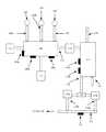
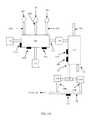
- FIGS. 1A and 1Billustrate an embodiment of a system to implement a method for generating electric power from at least one plasma source and a carbon feedstock in accordance with the present disclosure.
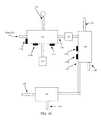
- FIG. 1Cdepicts a block diagram of an illustrative high-voltage electric field generator according to an embodiment.
- FIGS. 1A and 1Billustrate an embodiment of a system that may be used for generating power from H 2 O, CO 2 , O 2 , and a carbon feedstock. Improved efficiency may be obtained in part by having the fuel generating facility also produce at least some electric power to lessen the facility's dependence on exterior power supplies. Improved efficiency may also be obtained by a facility having multiple points of process control to properly adjust reaction temperatures and other process conditions to optimize the processes.
- a first fluid plasma, a second fluid plasma, and a third fluid plasmamay be introduced.
- the first fluid plasmamay be generated by exposing a first working fluid to a first high voltage electric field, such as may be generated by a first plasma torch 102 a
- the second fluid plasmamay be generated by exposing a second working fluid to a second high voltage electric field, such as may be generated by a second plasma torch 102 b
- the third fluid plasmamay be generated by exposing a third working fluid to a third high voltage electric field, such as may be generated by a third plasma torch 102 c .
- the first working fluidmay be carbon dioxide gas (CO 2 )
- the second working fluidmay be oxygen gas (O 2 )
- the third working fluidmay be water vapor (H 2 O).
- the first fluid plasma, second fluid plasma, and third fluid plasmamay each attain a temperature of about 20,000 degrees C. at the output of their respective plasma torches ( 102 a , 102 b , and 102 c ).
- Each of the one or more high-voltage electric field generators 102 a , 102 b , 102 c , 132may generally be any of various components that may be used to generate a high voltage potential.
- each of the one or more high-voltage electric field generators 102 a , 102 b , 102 c , 132may have at least one anode surface 150 , at least one cathode surface 155 , and an electric potential 160 between the anode surface and the cathode surface.
- a magnetic field 165 and an electric field 170may be generated when the electric potential 160 is applied between the at least one anode surface 150 and the at least one cathode surface 155 .
- a flow of gasmay be substantially perpendicular to the magnetic field 165 .
- the flow of gasmay be substantially parallel to the magnetic field 165 .
- the magnetic field 165 and the electric field 170may each have an effect on gas that flows through a gap between the anode surface 150 and the cathode surface 155 .
- the electric field 170may stabilize the gas and/or ionize the gas.
- the magnetic field 165may alter a spin and/or a velocity of the gas.
- the CO 2 , O 2 , and H 2 O in the first processing chamber 100may be used as working fluids for their respective plasma torches ( 102 a , 102 b , and 102 c ).
- each gasmay be exposed to high voltage electric fields.
- the gasesmay be reduced to free radical species (as examples, for H 2 O, these may include the hydroxyl radical OH., and for O 2 these may include the superoxide anion radical O2. ⁇ ) in addition to ionized species (for O 2 , these may include O ⁇ , O 2 ⁇ , O 2 + , and O + ).
- the types and amounts of reactive species created by exposure of the gases to high voltage electric fieldsmay differ from those generated by exposure of the gases to heat alone.
- exposing the first working fluid to a first high voltage electric fieldmay include providing an anode surface and a cathode surface separated by a distance to create a gap between the two surfaces.
- a first high voltage electric potentialmay be induced between the anode surface and the cathode surface, and the first working fluid may be induced to traverse the gap between the two surfaces.
- the gapmay generally be selected such that (for the electrical voltage selected), the electrical field is about 0.3 kV/cm to about 8.0 kV/cm, including about 0.3 kV/cm, about 0.3149 kV/com, about 0.5 kV/cm, about 0.75 kV/com, about 1.0 kV/com, about 1.25 kV/cm, about 1.5 kV/cm, about 1.574 kV/cm, about 2.0 kV/com, about 2.5 kV/cm, about 3.0 kV/cm, about 0.3149 kV/cm, about 3.5 kV/cm, about 4.0 kV/cm, about 4.5 kV/cm, about 5.0 kV/cm, about 5.5 kV/cm, about 6.0 kV/cm, about 6.5 kV/cm, about 7.0 kV/cm, about 7.5 kV/cm, about 7.559 kV/c
- Illustrative distancesmay be about 0.15 cm to about 0.65 cm, including about 0.15 cm, about 0.20 cm, about 0.25 cm, about 0.30 cm, about 0.3175 cm, about 0.35 cm, about 0.40 cm, about 0.45 cm, about 0.50 cm, about 0.55 cm, about 0.60 cm, about 0.65 cm, or any value or range between any two of these values (including endpoints).
- a voltage potentialmay be provided between the anode surface and the cathode surface.
- a first high voltage electric potentialmay be induced between the anode surface and the cathode surface, and the first working fluid may be induced to traverse the gap between the two surfaces.
- the high voltage potentialmay be about 2.4 kV times the gap distance in centimeters to about 60 kV times the gap distance in centimeters, including about 2.4 kV, about 5 kV, about 10 kV, about 20 kV, about 30 kV, about 40 kV, about 50 kV, about 60 kV, or any value or range between any two of these values (including endpoints).
- a voltage between the anode surface and the cathode surface(which is 0.3175 cm) is 2.4 kV, thereby resulting in an electrical field of about 7.559 kV/cm.
- the high-voltage electric potentialmay be an alternating current (AC) potential having a frequency of about 1 MHz to about 50 MHz, including about 1 MHz, about 5 MHz, about 10 MHz, about 20 MHz, about 25 MHz, about 30 MHz, about 40 MHz, about 50 MHz, or any value or range between any two of these values (including endpoints).
- ACalternating current
- the high-voltage electric potentialmay have a current of about 100 Amperes to about 1000 Amperes, including about 100 Amperes, about 200 Amperes, about 300 Amperes, about 400 Amperes, about 500 Amperes, about 600 Amperes, about 700 Amperes, about 800 Amperes, about 900 Amperes, about 1000 Amperes, or any value or range between any two of these values (including endpoints).
- exposing the second working fluid to a second high voltage electric fieldmay include providing an anode surface and a cathode surface separated by a distance to create a gap between the two surfaces.
- a second high voltage electric potentialmay be induced between the anode surface and the cathode surface, and the second working fluid may be induced to traverse the gap between the two surfaces.
- the gapmay generally be selected such that (for the electrical voltage selected), the electrical field is about 0.3 kV/cm to about 8.0 kV/cm, including about 0.3 kV/cm, about 0.3149 kV/com, about 0.5 kV/cm, about 0.75 kV/com, about 1.0 kV/com, about 1.25 kV/cm, about 1.5 kV/cm, about 1.574 kV/cm, about 2.0 kV/com, about 2.5 kV/cm, about 3.0 kV/cm, about 0.3149 kV/cm, about 3.5 kV/cm, about 4.0 kV/cm, about 4.5 kV/cm, about 5.0 kV/cm, about 5.5 kV/cm, about 6.0 kV/cm, about 6.5 kV/cm, about 7.0 kV/cm, about 7.5 kV/cm, about 7.559 kV/c
- Illustrative distancesmay be about 0.15 cm to about 0.65 cm, including about 0.15 cm, about 0.20 cm, about 0.25 cm, about 0.30 cm, about 0.3175 cm, about 0.35 cm, about 0.40 cm, about 0.45 cm, about 0.50 cm, about 0.55 cm, about 0.60 cm, about 0.65 cm, or any value or range between any two of these values (including endpoints).
- a voltage potentialmay be provided between the anode surface and the cathode surface.
- a second high voltage electric potentialmay be induced between the anode surface and the cathode surface, and the second working fluid may be induced to traverse the gap between the two surfaces.
- the high voltage potentialmay be about 2.4 kV times the gap distance in centimeters to about 60 kV times the gap distance in centimeters, including about 2.4 kV, about 5 kV, about 10 kV, about 20 kV, about 30 kV, about 40 kV, about 50 kV, about 60 kV, or any value or range between any two of these values (including endpoints).
- a voltage between the anode surface and the cathode surface(which is 0.3175 cm) is 2.4 kV, thereby resulting in an electrical field of about 7.559 kV/cm.
- the high-voltage electric potentialmay be an alternating current (AC) potential having a frequency of about 1 MHz to about 50 MHz, including about 1 MHz, about 5 MHz, about 10 MHz, about 20 MHz, about 25 MHz, about 30 MHz, about 40 MHz, about 50 MHz, or any value or range between any two of these values (including endpoints).
- ACalternating current
- the high-voltage electric potentialmay have a current of about 100 Amperes to about 1000 Amperes, including about 100 Amperes, about 200 Amperes, about 300 Amperes, about 400 Amperes, about 500 Amperes, about 600 Amperes, about 700 Amperes, about 800 Amperes, about 900 Amperes, about 1000 Amperes, or any value or range between any two of these values (including endpoints).
- exposing the third working fluid to a third high voltage electric fieldmay include providing an anode surface and a cathode surface separated by a distance to create a gap between the two surfaces.
- a third high voltage electric potentialmay be induced between the anode surface and the cathode surface, and the third working fluid may be induced to traverse the gap between the two surfaces.
- the gapmay generally be selected such that (for the electrical voltage selected), the electrical field is about 0.3 kV/cm to about 8.0 kV/cm, including about 0.3 kV/cm, about 0.3149 kV/com, about 0.5 kV/cm, about 0.75 kV/com, about 1.0 kV/com, about 1.25 kV/cm, about 1.5 kV/cm, about 1.574 kV/cm, about 2.0 kV/com, about 2.5 kV/cm, about 3.0 kV/cm, about 0.3149 kV/cm, about 3.5 kV/cm, about 4.0 kV/cm, about 4.5 kV/cm, about 5.0 kV/cm, about 5.5 kV/cm, about 6.0 kV/cm, about 6.5 kV/cm, about 7.0 kV/cm, about 7.5 kV/cm, about 7.559 kV/c
- Illustrative distancesmay be about 0.15 cm to about 0.65 cm, including about 0.15 cm, about 0.20 cm, about 0.25 cm, about 0.30 cm, about 0.3175 cm, about 0.35 cm, about 0.40 cm, about 0.45 cm, about 0.50 cm, about 0.55 cm, about 0.60 cm, about 0.65 cm, or any value or range between any two of these values (including endpoints).
- a voltage potentialmay be provided between the anode surface and the cathode surface.
- a third high voltage electric potentialmay be induced between the anode surface and the cathode surface, and the third working fluid may be induced to traverse the gap between the two surfaces.
- the high voltage potentialmay be about 2.4 kV times the gap distance in centimeters to about 60 kV times the gap distance in centimeters, including about 2.4 kV, about 5 kV, about 10 kV, about 20 kV, about 30 kV, about 40 kV, about 50 kV, about 60 kV, or any value or range between any two of these values (including endpoints).
- a voltage between the anode surface and the cathode surface(which is 0.3175 cm) is 2.4 kV, thereby resulting in an electrical field of about 7.559 kV/cm.
- the high-voltage electric potentialmay be an alternating current (AC) potential having a frequency of about 1 MHz to about 50 MHz, including about 1 MHz, about 5 MHz, about 10 MHz, about 20 MHz, about 25 MHz, about 30 MHz, about 40 MHz, about 50 MHz, or any value or range between any two of these values (including endpoints).
- ACalternating current
- the high-voltage electric potentialmay have a current of about 100 Amperes to about 1000 Amperes, including about 100 Amperes, about 200 Amperes, about 300 Amperes, about 400 Amperes, about 500 Amperes, about 600 Amperes, about 700 Amperes, about 800 Amperes, about 900 Amperes, about 1000 Amperes, or any value or range between any two of these values (including endpoints).
- anode and cathode surfaces contacting the first working fluid, the second working fluid, and the third working fluidmay be the same set of surfaces or they may differ. If each working fluid contacts an independent pair of anode and cathode surfaces, the respective gap distances may be essentially the same or different, and high voltage electric potentials to which the working fluids are exposed may have essentially the same or different characteristics.
- each source of the high voltage electric fieldsuch as those exemplified by plasma torches 102 a , 102 b , and 102 c , may be controlled by one or more control systems.
- Such control systemsmay be specific for all the plasma torches 102 a , 102 b , and 102 c together and may be different from or included with a control system for the entire power generating system.
- each plasma torch 102 a , 102 b , and 102 cmay have a separate control system.
- a control system for a plasma torch 102 a , 102 b , and 102 cmay include control functions for torch parameters, such as, but not limited to, the voltage of the high voltage electric field and a frequency of the high voltage electric field.
- Control of the torches 102 a , 102 b , and 102 cmay be based on one or more process measurements, including but not limited to, a measurement of a voltage applied to components that may generate the high voltage electric field, a current drain of a voltage supply for the high voltage electric field generators (such as plasma torches 102 a , 102 b , and 102 c ), the temperature of the plasma output of the high voltage electric field generators (provided by a temperature sensor 101 a ), and the composition of the plasma generated by the high voltage electric field generators (provided by a gas composition sensor 101 b ).
- each of the high voltage electric field generatorsmay be controlled according to one or more process algorithms.
- the plasma torches 102 a , 102 b , and 102 cmay be controlled according to the same process methods or algorithms (as provided by individual controllers or a single controller).
- each of the plasma torches 102 a , 102 b , and 102 cmay be controlled according to a different process method or algorithm (as provided by individual controllers or by a single controller).
- Each working fluidmay be supplied by its own working fluid source.
- CO 2may be supplied from a CO 2 source 104
- O 2may be supplied from an O 2 source 106
- water vapor (H 2 O)may be supplied from an H 2 O source 108 .
- control of the fluid plasma from each of the high voltage field sourcesmay also include control the amount of working fluid supplied to each of the high voltage field sources.
- the working fluid supply sources for the CO 2 , O 2 , and H 2 O,( 104 , 106 , and 108 , respectively) may also include control and measurement components.
- Such componentsmay include, without limitation, components to control the amount of the working fluid supplied by each of the working fluid supply sources (valves) and devices to measure the amount of each of the working fluid supplied (as non-limiting examples, by measuring chemical composition or pressure of the gas delivered). It may be further understood that such measurement and control devices may be controlled by one or more control systems, as disclosed above. Such control systems may be specific to one or more of the working fluid supply sources. Alternatively, all the working fluid supply sources may be controlled by the same control system. In an alternative embodiments, the working fluid supply sources may be controlled by a control system common to the entire power generation system.
- an alternative embodiment of the systemmay include three working fluids, exemplified by CO 2 , O 2 and H 2 O, that may be combined into one or two combined working fluids before being supplied to one or two high voltage electric field generators.
- CO 2 , O 2 and H 2 Omay be combined into a single combined working fluid to be supplied to a single plasma torch.
- the controllers associated with each of the supply sources for the CO 2 , O 2 and H 2 O,( 104 , 106 , and 108 , respectively) may cause a specific amount of each gas to be added to the combined working fluid to produce an optimized ratio of gasses.
- the controller associated with a single plasma torchmay cause the plasma torch to operate under optimum conditions for a specific ratio of gasses in the combined working fluid.
- the first fluid plasma, the second fluid plasma, and the third fluid plasma togethermay be directed to contact a carbon-based feed-stock within the first processing chamber, thereby creating a first fluid mixture.
- the carbon-based feed-stockmay be supplied from a carbon-based feed-stock supply 110 .
- the mechanical components used to transport the carbon-based feed-stock into the first processing chamber 100may be controlled according to some process parameters.
- the control of the transport of the carbon-based feed-stockmay be supplied by a control system.
- a control systemmay be specific to the mechanical components used to transport the carbon-based feed-stock into the first processing chamber 100 .
- such a control systemmay be included into a control system to control the entire power generation system.
- examples of the carbon-based feed-stockmay include one or more of organic waste (wood chips, sawdust, material made from organic material such as papers, wood furniture), municipal waste, man-made organic material (synthetic carpets, tires, compact discs, plastics, rubbers), coal, and biomass.
- organic wastewood chips, sawdust, material made from organic material such as papers, wood furniture
- municipal wasteman-made organic material (synthetic carpets, tires, compact discs, plastics, rubbers), coal, and biomass.
- the first processing chamber 100may also be maintained at a vacuum.
- vacuummay be provided by means of a vacuum pump equivalent device 111 .
- the first process chamber 100may be maintained at a pressure of about 50 kPa (0.5 atmospheres). The pressure within the first processing chamber 100 may be monitored by a pressure sensor 101 c.
- the first fluid mixturewhile in the first processing chamber 100 , may attain temperatures of about 4000 degrees C. to about 6000 degrees C. Higher or lower temperatures may be attained according to the conditions under which the high voltage field generators operate.
- the first fluid mixturemay be cooled within the first processing chamber 100 , at an exit port of the first processing chamber 112 , in a transport device (such as a pipe or other duct-work) at an exit of the first processing chamber, or at a combination of these locations through the action of a coolant addition device 114 .
- the coolantmay include liquid oxygen (LOX).
- An amount of coolant introduced into the first fluid mixture by the coolant addition device 114may be controlled by a control system.
- the amount of the coolant added to the first fluid mixturemay be controlled according to a temperature of the first fluid mixture, a composition of the first fluid mixture, or other measured parameters of the first fluid mixture.
- a control systemmay be associated only with the coolant addition device 114 .
- such a control systemmay be incorporated into a system for controlling the entire power generation system.
- the addition of the coolant to the first fluid mixturemay reduce the temperature of the resulting fluid mixture (an admixed first fluid mixture) to about 1450 degrees C. to about 1650 degrees C. It may be further appreciated that the admixed first fluid mixture may have a composition different from that of the first fluid mixture.
- the admixed first fluid mixturemay be transported to a first heat exchange device 118 where it may exchange at least some of its heat with a heat exchange material, and thus cool to form a second fluid mixture.
- the first heat exchange device 118may be a first heat recovery steam generator (HRSG).
- the first heat exchange device 118may allow transfer of at least some heat from the admixed first fluid mixture to a heat exchange material, such as water. Water may enter the first heat exchange device 118 through a first water input port 120 , and the amount of water may be controlled by a control system.
- the heated first heat exchange materialwhich may include steam as a non-limiting example, may exit the first heat exchange device 118 by means of a first output port 122 .
- the heated first heat exchange materialmay be further transported to a first electric turbine to generate a first supply of electric power.
- the first heat exchange materialmay be water, which may be converted to a first supply of steam in the first heat exchange device 118 .
- the first supply of steammay be cooled to liquid water.
- the liquid watermay be returned to the first heat exchange device 118 to be reheated by more of the admixed first fluid mixture.
- the first supply of steamafter activating the first electric turbine, may be returned to a working fluid source 108 to be supplied to a high voltage electric field generator (such as plasma torch 102 c ).
- the second fluid mixturemay have a temperature of about 38 degrees C. to about 200 degrees C.
- the temperature within the first heat exchange device 118may be monitored by a temperature sensor 119 a .
- the composition of the second fluid mixturemay be different from that of the first fluid mixture and that of the admixed first fluid mixture.
- the composition of the second fluid mixturemay be monitored within or at the exit of the first heat exchange device 118 by means of a composition sensor 119 b .
- the components of the second fluid mixturemay be separated by a gas separator 128 and the individual components may be directed to individual gas holding containers 129 a , 129 b.
- the individual componentsmay include one or more of hydrogen gas (H 2 ), and carbon monoxide (CO).
- the gas separatormay comprise, as non-limiting examples, a membrane separation system, a molecular sieve, or a combination thereof.
- the individual gas holding containers 129 a , 129 bmay each include an outflow metering device. Each outflow metering device may be controlled by a controller. Alternatively, the outflow metering devices of each of the gas holding containers 129 a , 129 b may be controlled by the same controller.
- Each gas holding container 129 a , 129 bmay also have a gas output port associated with the corresponding outflow metering devices. The gas output port of each of the gas holding containers 129 a , 129 b may direct the gas from its gas holding container into a common supply duct 132 . Some portion of the second fluid mixture may also be directed into the common supply duct 132 .
- the outflow metering devices of each of the gas holding containers 129 a , 129 bmay be controlled to permit an amount of gas into the common supply duct 132 to create a syngas mixture having a controlled composition.
- the syngas mixture compositionmay be controlled based on one or more gas composition sensors 133 associated with the common supply duct 132 .
- the syngas mixture compositionmay be controlled based on a volume of gas emitted by the outflow metering devices of each of the individual gas holding containers 129 a , 129 b .
- the syngas mixture compositionmay be controlled based on the pressure of gas contained in each of the gas holding containers 129 a , 129 b .
- a composition of the syngasmay include 1 part CO to 2 parts H 2 (1:2). In other embodiments, the ratio of CO to H 2 in the syngas may be from about 1:1.2 to about 1:3.
- the syngas mixturemay be directed by the common supply duct 132 into a second processing chamber 130 .
- the syngasmay be heated by one or more high voltage electrical field generator 132 .
- the plasmamay attain a temperature of about 20,000 degrees C. at the output of additional high voltage electrical field generators 132 , and the second processing chamber 130 may attain temperatures of about 4000 degrees C. to about 6000 degrees C.
- a third fluid mixturemay be obtained from the syngas.
- the second processing chamber 130may be maintained at a pressure (greater than, equal to, or less than atmospheric pressure) by means of a vacuum pump 133 or similar device.
- Process control variables within the second processing chamber 130may be monitored by any number of sensors including, but not limited to, a temperature sensor 131 a , a gas composition sensor 131 b , or a pressure sensor 131 c.
- the third fluid mixturemay be cooled within the second processing chamber 130 , at an exit port of the first processing chamber 134 , in a transport device (such as a pipe or other duct-work) at an exit of the first processing chamber, or at a combination of these locations through the action of a second coolant addition device 135 .
- the coolantmay include liquid oxygen (LOX).
- An amount of coolant introduced into the third fluid mixture by the second coolant addition device 135may be controlled by a control system.
- the amount of the coolant added to the third fluid mixturemay be controlled according to a temperature of the third fluid mixture, a composition of the third fluid mixture, or other measured parameters of the third fluid mixture.
- Such a control systemmay be associated only with the second coolant addition device. Alternatively, such a control system may be incorporated into a system for controlling the entire power generation system.
- the addition of the second coolant to the third fluid mixturemay reduce the temperature of the resulting fluid mixture (an admixed third fluid mixture) to about 1450 degrees C. to about 1650 degrees C.
- the heated admixed third fluid mixturemay be transported to a second heat exchange device 136 where it may exchange at least some of its heat with a heat exchange material, and thus cool to form an effluent mixture.
- the second heat exchange device 136may be a second heat recovery steam generator (HRSG).
- the second heat exchange device 136may allow transfer of at least some heat from the third admixed fluid mixture to a second heat exchange material, such as water. Water may enter the second heat exchange device 136 through a second water input port 138 and the amount of water may be controlled by a control system.
- the heated second heat exchange materialwhich may include steam as a non-limiting example, may exit the second heat exchange device 136 by means of a second output port 140 .
- the heated second heat exchange materialmay be further transported to a second electric turbine to generate a second supply of electric power.
- the second heat exchange materialmay be water, which may be converted to a second supply of steam in the second heat exchange device 136 .
- the second supply of steammay be cooled to liquid water.
- the liquid watermay be returned to the second heat exchange device 136 to be reheated by more of the third fluid mixture.
- the second supply of steamafter activating the second electric turbine, may be returned to a working fluid source 108 to be supplied to a high voltage electric field generator (such as plasma torch 102 c ).
- the temperature of the admixed first fluid entering the first heat exchange device 118may be different than the temperature of the heated admixed third fluid entering the second heat exchange device 136 .
- the power derived from the heated first heat exchange material through the first electric turbinemay be different from that derived from the heated second heat exchange material through the second electric turbine.
- process parameters in the second heat exchange device 136may be monitored by a temperature 137 a and a gas composition sensor 137 b.
- the second electric turbinemay be the same as the first electric turbine.
- the effluent fluid from the second heat exchange device 136may be directed via an output port 142 to any number of cleaning devices 144 to remove unwanted components, non-limiting examples being sulfur-containing material and mercury-containing materials.
- cleaning devices 144may include, without limitation, a wet limestone scrubber.
- the resultant gas mixture exiting the cleaning devices 144may include primarily carbon dioxide CO 2 and water H 2 O.
- gasesmay be released into the atmosphere.
- the gasesmay be returned to be re-used at appropriate points in the process.
- the CO 2may be returned to the CO 2 supply source 104 through a CO 2 output port 146
- the watermay be returned to the water supply source 108 for re-used in the first processing chamber 100 through a water supply output port 148 .
- the system disclosed abovemay make use of data derived from a number of sensors of processor parameters associated with a variety of stages including, without limitation, the first processing chamber 100 , the second processing chamber 130 , the first heat exchange device 118 , the second heat exchange device 136 and the common supply duct 132 .
- Data from the sensorsmay be used by one or more control systems used to control any one or more devices including the one or more high voltage electric field generators ( 102 a , 102 b , 102 c , 132 ), vacuum pumps ( 111 , 133 ), suppliers of working gases to the electric field generators ( 102 a , 102 b , 102 c , 132 ), and similar devices.
- compositions, methods, and devicesare described in terms of “comprising” various components or steps (interpreted as meaning “including, but not limited to”), the compositions, methods, and devices can also “consist essentially of” or “consist of” the various components and steps, and such terminology should be interpreted as defining essentially closed-member groups.
Landscapes
- Chemical & Material Sciences (AREA)
- Engineering & Computer Science (AREA)
- Organic Chemistry (AREA)
- Chemical Kinetics & Catalysis (AREA)
- Physics & Mathematics (AREA)
- Plasma & Fusion (AREA)
- Oil, Petroleum & Natural Gas (AREA)
- Combustion & Propulsion (AREA)
- Health & Medical Sciences (AREA)
- General Health & Medical Sciences (AREA)
- General Chemical & Material Sciences (AREA)
- Spectroscopy & Molecular Physics (AREA)
- Mechanical Engineering (AREA)
- General Engineering & Computer Science (AREA)
- Inorganic Chemistry (AREA)
- Toxicology (AREA)
- High Energy & Nuclear Physics (AREA)
- Sustainable Development (AREA)
- Sustainable Energy (AREA)
- Life Sciences & Earth Sciences (AREA)
- Environmental & Geological Engineering (AREA)
- Physical Or Chemical Processes And Apparatus (AREA)
- Hydrogen, Water And Hydrids (AREA)
Abstract
Description
Claims (20)
Priority Applications (1)
| Application Number | Priority Date | Filing Date | Title |
|---|---|---|---|
| US14/426,093US9273570B2 (en) | 2012-09-05 | 2013-09-05 | Methods for power generation from H2O, CO2, O2 and a carbon feed stock |
Applications Claiming Priority (3)
| Application Number | Priority Date | Filing Date | Title |
|---|---|---|---|
| US201261697148P | 2012-09-05 | 2012-09-05 | |
| PCT/US2013/058305WO2014039706A1 (en) | 2012-09-05 | 2013-09-05 | Methods for power generation from h2o, co2, o2 and a carbon feed stock |
| US14/426,093US9273570B2 (en) | 2012-09-05 | 2013-09-05 | Methods for power generation from H2O, CO2, O2 and a carbon feed stock |
Publications (2)
| Publication Number | Publication Date |
|---|---|
| US20150275705A1 US20150275705A1 (en) | 2015-10-01 |
| US9273570B2true US9273570B2 (en) | 2016-03-01 |
Family
ID=55538141
Family Applications (1)
| Application Number | Title | Priority Date | Filing Date |
|---|---|---|---|
| US14/426,093Expired - Fee RelatedUS9273570B2 (en) | 2012-09-05 | 2013-09-05 | Methods for power generation from H2O, CO2, O2 and a carbon feed stock |
Country Status (6)
| Country | Link |
|---|---|
| US (1) | US9273570B2 (en) |
| EP (1) | EP2904221A4 (en) |
| KR (1) | KR101581261B1 (en) |
| BR (1) | BR112015004831A2 (en) |
| HK (1) | HK1212413A1 (en) |
| WO (1) | WO2014039706A1 (en) |
Families Citing this family (4)
| Publication number | Priority date | Publication date | Assignee | Title |
|---|---|---|---|---|
| IL249923B (en)* | 2017-01-03 | 2018-03-29 | Shohat Tsachi | Smart waste container |
| DE102017126886B3 (en)* | 2017-11-15 | 2019-01-24 | Graforce Gmbh | Method and device for plasma-induced water splitting |
| WO2021150270A1 (en)* | 2020-01-24 | 2021-07-29 | Massachusetts Institute Of Technology | Control of cleanup engine in a biomass conversion system |
| US11524899B2 (en)* | 2021-04-01 | 2022-12-13 | Aquasource Technologies Corporation | System and method for removal of carbon from carbon dioxide |
Citations (121)
| Publication number | Priority date | Publication date | Assignee | Title |
|---|---|---|---|---|
| US1746464A (en) | 1925-07-21 | 1930-02-11 | Fischer Franz | Process for the production of paraffin-hydrocarbons with more than one carbon atom |
| GB573982A (en) | 1941-01-14 | 1945-12-17 | Synthetic Oils Ltd | Improvements in or relating to methods of producing hydrocarbon oils from gaseous mixtures of hydrogen and carbon monoxide |
| US3979205A (en)* | 1971-04-07 | 1976-09-07 | Wanzenberg Fritz Walter | Metal recovery method |
| US4466807A (en) | 1981-03-10 | 1984-08-21 | Skf Steel Engineering Aktiebolag | Manufacture of a gas containing monoxide and hydrogen gas from a starting material containing carbon and/or hydrocarbon |
| US4508040A (en) | 1982-01-18 | 1985-04-02 | Skf Steel Engineering Aktiebolag | Method and plant for conversion of waste material to stable final products |
| US4591428A (en) | 1984-03-01 | 1986-05-27 | Shell Oil Company | Continuous process for the catalytic treatment of hydrocarbon oils |
| US4770109A (en)* | 1987-05-04 | 1988-09-13 | Retech, Inc. | Apparatus and method for high temperature disposal of hazardous waste materials |
| US4831944A (en) | 1987-01-22 | 1989-05-23 | Aerospatiale Societe Nationale Industrielle | Process and device for destroying solid waste by pyrolysis |
| US4845334A (en) | 1988-01-26 | 1989-07-04 | Oregon Metallurgical Corporation | Plasma furnace inert gas recycling system and process |
| US4898748A (en) | 1988-08-31 | 1990-02-06 | The Board Of Trustees Of Leland Stanford Junior University | Method for enhancing chemical reactivity in thermal plasma processes |
| US5046144A (en) | 1987-10-15 | 1991-09-03 | Rockwool International A/S | Method and furnace for the preparation of a melt for mineral wool production |
| US5107517A (en) | 1987-04-30 | 1992-04-21 | Oy Partek Ab | Melting furnace |
| US5136137A (en)* | 1987-05-04 | 1992-08-04 | Retech, Inc. | Apparatus for high temperature disposal of hazardous waste materials |
| US5138959A (en) | 1988-09-15 | 1992-08-18 | Prabhakar Kulkarni | Method for treatment of hazardous waste in absence of oxygen |
| US5288969A (en) | 1991-08-16 | 1994-02-22 | Regents Of The University Of California | Electrodeless plasma torch apparatus and methods for the dissociation of hazardous waste |
| US5301620A (en) | 1993-04-01 | 1994-04-12 | Molten Metal Technology, Inc. | Reactor and method for disassociating waste |
| US5319176A (en) | 1991-01-24 | 1994-06-07 | Ritchie G. Studer | Plasma arc decomposition of hazardous wastes into vitrified solids and non-hazardous gasses |
| US5493578A (en) | 1992-09-24 | 1996-02-20 | Ishikawajima-Harima Heavy Industries Co., Ltd. | Ash melting furnace |
| US5534659A (en) | 1994-04-18 | 1996-07-09 | Plasma Energy Applied Technology Incorporated | Apparatus and method for treating hazardous waste |
| US5544597A (en) | 1995-08-29 | 1996-08-13 | Plasma Technology Corporation | Plasma pyrolysis and vitrification of municipal waste |
| US5611947A (en)* | 1994-09-07 | 1997-03-18 | Alliant Techsystems, Inc. | Induction steam plasma torch for generating a steam plasma for treating a feed slurry |
| US5673635A (en) | 1995-06-12 | 1997-10-07 | L.E. Maxwitat | Process for the recycling of organic wastes |
| US5725616A (en) | 1991-12-12 | 1998-03-10 | Kvaerner Engineering A.S. | Method for combustion of hydrocarbons |
| US5798496A (en) | 1995-01-09 | 1998-08-25 | Eckhoff; Paul S. | Plasma-based waste disposal system |
| US5935293A (en) | 1995-03-14 | 1999-08-10 | Lockheed Martin Idaho Technologies Company | Fast quench reactor method |
| US5958264A (en) | 1996-10-21 | 1999-09-28 | Pyrogenesis Inc. | Plasma gasification and vitrification of ashes |
| US6127645A (en) | 1995-02-02 | 2000-10-03 | Battelle Memorial Institute | Tunable, self-powered arc plasma-melter electro conversion system for waste treatment and resource recovery |
| CN1268550A (en) | 1999-03-24 | 2000-10-04 | Abb研究有限公司 | Method for synthesizing fuel |
| US6153852A (en)* | 1999-02-12 | 2000-11-28 | Thermal Conversion Corp | Use of a chemically reactive plasma for thermal-chemical processes |
| US6173002B1 (en) | 1999-04-21 | 2001-01-09 | Edgar J. Robert | Electric arc gasifier as a waste processor |
| CA2379892A1 (en) | 1999-07-29 | 2001-02-08 | David Systems & Technology S.L. | Plasma converter of fossil fuels into hydrogen-rich gas |
| US6187226B1 (en) | 1995-03-14 | 2001-02-13 | Bechtel Bwxt Idaho, Llc | Thermal device and method for production of carbon monoxide and hydrogen by thermal dissociation of hydrocarbon gases |
| US6215678B1 (en) | 1995-02-02 | 2001-04-10 | Integrated Environmental Technologies, Llc | Arc plasma-joule heated melter system for waste treatment and resource recovery |
| US6289851B1 (en) | 2000-10-18 | 2001-09-18 | Institute Of Gas Technology | Compact low-nox high-efficiency heating apparatus |
| US20020000085A1 (en) | 1998-11-25 | 2002-01-03 | Hall Kenneth R. | Method for converting natural gas to liquid hydrocarbons |
| US6355904B1 (en) | 1996-06-07 | 2002-03-12 | Science Applications International Corporation | Method and system for high-temperature waste treatment |
| US20020040889A1 (en) | 1999-12-20 | 2002-04-11 | Research Triangle Institute | Plasma furnace disposal of hazardous wastes |
| US6372156B1 (en)* | 1999-08-19 | 2002-04-16 | Bechtel Bwxt Idaho, Llc | Methods of chemically converting first materials to second materials utilizing hybrid-plasma systems |
| US20020151604A1 (en) | 1999-12-21 | 2002-10-17 | Detering Brent A. | Hydrogen and elemental carbon production from natural gas and other hydrocarbons |
| EP1270508A1 (en) | 2001-06-26 | 2003-01-02 | Hydro Tech International Inc. | Process and device for producing hydrogen |
| US6505567B1 (en) | 2001-11-26 | 2003-01-14 | Alstom (Switzerland) Ltd | Oxygen fired circulating fluidized bed steam generator |
| US20030029796A1 (en) | 2000-12-28 | 2003-02-13 | Takaaki Maekawa | Apparatus for purifying water containing dissolved organic matters and trace harmful substances |
| US6524538B2 (en) | 1999-04-28 | 2003-02-25 | Hana Barankova | Method and apparatus for plasma treatment of gas |
| US20030065042A1 (en) | 2001-10-01 | 2003-04-03 | Shaw John M. | Methanol production process |
| US20030209174A1 (en) | 2002-05-08 | 2003-11-13 | Chan Benjamin Chun Pong | Hazardous waste treatment method and apparatus |
| US20040134517A1 (en) | 1996-10-16 | 2004-07-15 | Clark Steve L. | Process for cleaning hydrocarbons from soils |
| US6821500B2 (en) | 1995-03-14 | 2004-11-23 | Bechtel Bwxt Idaho, Llc | Thermal synthesis apparatus and process |
| WO2005005009A2 (en) | 2003-06-30 | 2005-01-20 | Bar-Gadda, Llc. | Dissociation of molecular water into molecular hydrogen |
| US6874434B1 (en) | 2003-04-18 | 2005-04-05 | Bigelow Aerospace | Biomass waste disposal method and apparatus |
| US6971323B2 (en) | 2004-03-19 | 2005-12-06 | Peat International, Inc. | Method and apparatus for treating waste |
| US6976362B2 (en)* | 2001-09-25 | 2005-12-20 | Rentech, Inc. | Integrated Fischer-Tropsch and power production plant with low CO2 emissions |
| US6987792B2 (en) | 2001-08-22 | 2006-01-17 | Solena Group, Inc. | Plasma pyrolysis, gasification and vitrification of organic material |
| US20060060464A1 (en) | 2002-05-08 | 2006-03-23 | Chang Chak M T | Plasma formed in a fluid |
| US20060112639A1 (en) | 2003-11-29 | 2006-06-01 | Nick Peter A | Process for pyrolytic heat recovery enhanced with gasification of organic material |
| US7070634B1 (en)* | 2003-11-03 | 2006-07-04 | Wang Chi S | Plasma reformer for hydrogen production from water and fuel |
| CN1810938A (en) | 2005-08-24 | 2006-08-02 | 周开根 | Method of synthesizing fuel gas with water and oil and its burner |
| US20060201157A1 (en) | 2005-03-11 | 2006-09-14 | Villalobos Victor M | Arc-hydrolysis steam generator apparatus and method |
| US20060233699A1 (en) | 2003-04-15 | 2006-10-19 | Mills Randell L | Plasma reactor and process for producing lower-energy hydrogen species |
| US20070017228A1 (en) | 2005-07-06 | 2007-01-25 | Integrated Environmental Technologies, Llc | Method for enhancing the efficient operation of electrical power plants and energy storage |
| US20070186474A1 (en) | 2006-02-14 | 2007-08-16 | Gas Technology Institute | Plasma assisted conversion of carbonaceous materials into a gas |
| US7279655B2 (en)* | 2003-06-11 | 2007-10-09 | Plasmet Corporation | Inductively coupled plasma/partial oxidation reformation of carbonaceous compounds to produce fuel for energy production |
| US20070253874A1 (en) | 2001-07-16 | 2007-11-01 | Todd Foret | System, method and apparatus for treating liquids with wave energy from plasma |
| US20070266633A1 (en) | 2006-05-05 | 2007-11-22 | Andreas Tsangaris | Gas Reformulating System Using Plasma Torch Heat |
| US20070267289A1 (en) | 2006-04-06 | 2007-11-22 | Harry Jabs | Hydrogen production using plasma- based reformation |
| US20070272131A1 (en) | 2003-04-04 | 2007-11-29 | Pierre Carabin | Two-Stage Plasma Process For Converting Waste Into Fuel Gas And Apparatus Therefor |
| US7335320B2 (en) | 2001-03-06 | 2008-02-26 | Alchemix Corporation | Method for the production of hydrogen-containing gaseous mixtures |
| US20080083701A1 (en) | 2006-10-04 | 2008-04-10 | Mks Instruments, Inc. | Oxygen conditioning of plasma vessels |
| US7384619B2 (en) | 2003-06-30 | 2008-06-10 | Bar-Gadda, Llc | Method for generating hydrogen from water or steam in a plasma |
| US20080147241A1 (en) | 2006-05-05 | 2008-06-19 | Placso Energy Group Inc. | Control System for the Conversion of Carbonaceous Feedstock into Gas |
| US20080184621A1 (en) | 2006-10-02 | 2008-08-07 | Clark Steve L | Reduced-emission gasification and oxidation of hydrocarbon materials for power generation |
| US20080202028A1 (en) | 2005-06-03 | 2008-08-28 | Plasco Energy Group Inc. | System For the Conversion of Carbonaceous Fbedstocks to a Gas of a Specified Composition |
| US20080209807A1 (en) | 2006-05-05 | 2008-09-04 | Andreas Tsangaris | Low Temperature Gasification Facility with a Horizontally Oriented Gasifier |
| US20080222956A1 (en) | 2005-06-03 | 2008-09-18 | Plasco Energy Group Inc. | System for the Conversion of Coal to a Gas of Specified Composition |
| US20080223047A1 (en) | 2006-10-19 | 2008-09-18 | Troy Lee Oliver | Xplogen TM: a system, method, and apparatus for generating energy from a series of dissociation reactions |
| WO2008130260A1 (en) | 2007-04-18 | 2008-10-30 | Sgc Energia Sgps, S.A. | Waste to liquid hydrocarbon refinery system |
| US20080277265A1 (en) | 2007-05-11 | 2008-11-13 | Plasco Energy Group, Inc. | Gas reformulation system comprising means to optimize the effectiveness of gas conversion |
| US20080283411A1 (en) | 2007-05-04 | 2008-11-20 | Eastman Craig D | Methods and devices for the production of Hydrocarbons from Carbon and Hydrogen sources |
| US20080283153A1 (en) | 2007-05-09 | 2008-11-20 | Air Products And Chemicals, Inc. | Furnace atmosphere activation method and apparatus |
| US20080290322A1 (en) | 2005-05-10 | 2008-11-27 | Hartmut Hederer | Method for Heating and Partial Oxidation of a Steam/Natural Gas Mixture After a Primary Reformer |
| US20090038958A1 (en) | 2007-07-06 | 2009-02-12 | Coyle Edward L | Method and Apparatus for a Low Cost and Carbon Free Point of Use Dissociation of Water into Elemental Gases and Production of Hydrogen Related Power |
| US20090133407A1 (en) | 2007-11-28 | 2009-05-28 | Nrg Energy, Inc. | Plasma gasification system |
| US20090188127A1 (en) | 2004-07-19 | 2009-07-30 | Earthrenew, Inc. | Process and System for Drying and Heat Treating Materials |
| US7576296B2 (en) | 1995-03-14 | 2009-08-18 | Battelle Energy Alliance, Llc | Thermal synthesis apparatus |
| US7622693B2 (en) | 2001-07-16 | 2009-11-24 | Foret Plasma Labs, Llc | Plasma whirl reactor apparatus and methods of use |
| US20090307975A1 (en) | 2006-07-31 | 2009-12-17 | Bw-Energiesysteme Gmbh | Method for reprocessing combustion products from fossil fuels |
| WO2009156761A2 (en) | 2008-06-25 | 2009-12-30 | Horizon Ventures Limited | Processing of waste |
| US20100050654A1 (en) | 2008-07-31 | 2010-03-04 | Alstom Technology Ltd. | System for hot solids combustion and gasification |
| US7674443B1 (en) | 2008-08-18 | 2010-03-09 | Irvin Davis | Zero emission gasification, power generation, carbon oxides management and metallurgical reduction processes, apparatus, systems, and integration thereof |
| US20100065781A1 (en) | 2005-10-14 | 2010-03-18 | Commissariat A L'energie Atomique | Device for Gasification of Biomass and Organic Waste Under High Temperature and with an External Energy Supply in Order to Generate a High-Quality Synthetic Gas |
| WO2010056462A1 (en) | 2008-11-12 | 2010-05-20 | Uni-Control, Llc | Biological water-gas shift reaction system comprising plasma gasification |
| US20100167139A1 (en) | 2003-09-23 | 2010-07-01 | Synfuels International, Inc. | Process for the conversion of natural gas to hydrocarbon liquids |
| US20100229522A1 (en) | 2009-03-16 | 2010-09-16 | Jim Kingzett | Plasma-Assisted E-Waste Conversion Techniques |
| US7832344B2 (en) | 2006-02-28 | 2010-11-16 | Peat International, Inc. | Method and apparatus of treating waste |
| US20100298449A1 (en) | 2006-08-08 | 2010-11-25 | Ifp | Method of producing synthetic gas with partial oxidation and steam reforming |
| US7845411B2 (en) | 2006-10-20 | 2010-12-07 | Shell Oil Company | In situ heat treatment process utilizing a closed loop heating system |
| US20110067376A1 (en) | 2009-03-16 | 2011-03-24 | Geovada, Llc | Plasma-based waste-to-energy techniques |
| US20110162958A1 (en) | 2007-10-11 | 2011-07-07 | Moon-Ki Cho | Plasma decomposition apparatus and method for carbon dioxide |
| US7981371B2 (en) | 2004-02-18 | 2011-07-19 | Commissariat A L'energie Atomique | Device and method for destroying liquid, powder or gaseous waste using an inductively coupled plasma |
| WO2011091327A1 (en) | 2010-01-21 | 2011-07-28 | Usa Green Energy Group, Llc | Generating steam from carbonaceous material |
| US20110212012A1 (en) | 2010-02-13 | 2011-09-01 | Mcalister Technologies, Llc | Carbon-based durable goods and renewable fuel from biomass waste dissociation |
| US20110265698A1 (en) | 2010-05-03 | 2011-11-03 | Powerdyne, Inc. | System and method for reutilizing co2 from combusted carbonaceous material |
| US20110286893A1 (en) | 2009-01-06 | 2011-11-24 | The University Of Sheffield | Plasma microreactor apparatus, sterilisation unit and analyser |
| US20120000115A1 (en) | 2010-07-01 | 2012-01-05 | Aarmonia Chemicals Private, Ltd. | Diesel fuel additive |
| US8129654B2 (en) | 2006-04-04 | 2012-03-06 | Cheju National University Industry Academic Cooperation Foundation | DC arc plasmatron and method of using the same |
| US20120070347A1 (en) | 2010-03-01 | 2012-03-22 | Plasco Energy Group, Inc. | Carbon Conversion System with Integrated Processing Zones |
| WO2012039751A2 (en) | 2010-09-24 | 2012-03-29 | James Charles Juranitch | Renewable combined cycle low turbine boost |
| US20120090985A1 (en) | 2010-10-01 | 2012-04-19 | Drexel University | Non-equilibrium gliding arc plasma system for co2 dissociation |
| US8168128B2 (en) | 2005-10-26 | 2012-05-01 | Edwards Limited | Plasma reactor |
| US20120114877A1 (en) | 2010-11-05 | 2012-05-10 | Synos Technology, Inc. | Radical Reactor with Multiple Plasma Chambers |
| WO2012064936A1 (en) | 2010-11-10 | 2012-05-18 | Air Products And Chemicals, Inc. | Syngas produced by plasma gasification |
| US8199790B2 (en) | 2007-11-02 | 2012-06-12 | Plasma Waste Recycling, Inc. | Reactor vessel for plasma gasification |
| WO2012077198A1 (en) | 2010-12-08 | 2012-06-14 | トヨタ自動車株式会社 | Fuel production system |
| US8216433B2 (en) | 2006-03-07 | 2012-07-10 | University Of The Ryukyus | Plasma generator and method of generating plasma using the same |
| US8252244B2 (en) | 2008-02-08 | 2012-08-28 | Peat International, Inc. | Method and apparatus of treating waste |
| US8303916B2 (en) | 2008-02-01 | 2012-11-06 | Oscura, Inc. | Gaseous transfer in multiple metal bath reactors |
| US20120291436A1 (en) | 2011-05-16 | 2012-11-22 | Powerdyne Inc. | Steam generation system |
| WO2012177666A1 (en) | 2011-06-21 | 2012-12-27 | Staton Vernon Eric | Apparatus and method for hydrocarbon pyrolysis |
| US8367005B2 (en) | 2007-07-12 | 2013-02-05 | Imagineering, Inc. | Gas processing apparatus, gas processing system, and gas processing method, and exhaust gas processing system and internal combustion engine using the same |
| US8518162B2 (en) | 2005-08-15 | 2013-08-27 | Edwards Limited | Method of treating a gas stream |
| US8519354B2 (en) | 2008-02-12 | 2013-08-27 | Purdue Research Foundation | Low temperature plasma probe and methods of use thereof |
| US20130300121A1 (en) | 2009-07-17 | 2013-11-14 | Green Energy And Technology Sdn. Bhd. | Method and system for producing energy from waste |
Family Cites Families (3)
| Publication number | Priority date | Publication date | Assignee | Title |
|---|---|---|---|---|
| KR100631719B1 (en)* | 2004-12-27 | 2006-10-11 | 엘지전자 주식회사 | Gas supply structure of plasma polymerization apparatus |
| KR101338266B1 (en)* | 2007-07-17 | 2013-12-09 | 플라스코에너지 아이피 홀딩스, 에스.엘., 빌바오, 샤프하우젠 브랜치 | A gas reformulation system comprising means to optimize the effectiveness of gas conversion |
| KR101255152B1 (en)* | 2010-12-01 | 2013-04-22 | 한국기초과학지원연구원 | Power generation system using plasma gasifier |
- 2013
- 2013-09-05USUS14/426,093patent/US9273570B2/ennot_activeExpired - Fee Related
- 2013-09-05BRBR112015004831Apatent/BR112015004831A2/ennot_activeIP Right Cessation
- 2013-09-05KRKR1020157008600Apatent/KR101581261B1/ennot_activeExpired - Fee Related
- 2013-09-05EPEP13835933.6Apatent/EP2904221A4/ennot_activeWithdrawn
- 2013-09-05WOPCT/US2013/058305patent/WO2014039706A1/enactiveApplication Filing
- 2013-09-05HKHK16100168.8Apatent/HK1212413A1/enunknown
Patent Citations (137)
| Publication number | Priority date | Publication date | Assignee | Title |
|---|---|---|---|---|
| US1746464A (en) | 1925-07-21 | 1930-02-11 | Fischer Franz | Process for the production of paraffin-hydrocarbons with more than one carbon atom |
| GB573982A (en) | 1941-01-14 | 1945-12-17 | Synthetic Oils Ltd | Improvements in or relating to methods of producing hydrocarbon oils from gaseous mixtures of hydrogen and carbon monoxide |
| US3979205A (en)* | 1971-04-07 | 1976-09-07 | Wanzenberg Fritz Walter | Metal recovery method |
| US4466807A (en) | 1981-03-10 | 1984-08-21 | Skf Steel Engineering Aktiebolag | Manufacture of a gas containing monoxide and hydrogen gas from a starting material containing carbon and/or hydrocarbon |
| US4508040A (en) | 1982-01-18 | 1985-04-02 | Skf Steel Engineering Aktiebolag | Method and plant for conversion of waste material to stable final products |
| US4591428A (en) | 1984-03-01 | 1986-05-27 | Shell Oil Company | Continuous process for the catalytic treatment of hydrocarbon oils |
| US4831944A (en) | 1987-01-22 | 1989-05-23 | Aerospatiale Societe Nationale Industrielle | Process and device for destroying solid waste by pyrolysis |
| US5107517A (en) | 1987-04-30 | 1992-04-21 | Oy Partek Ab | Melting furnace |
| US5136137A (en)* | 1987-05-04 | 1992-08-04 | Retech, Inc. | Apparatus for high temperature disposal of hazardous waste materials |
| US4770109A (en)* | 1987-05-04 | 1988-09-13 | Retech, Inc. | Apparatus and method for high temperature disposal of hazardous waste materials |
| US5046144A (en) | 1987-10-15 | 1991-09-03 | Rockwool International A/S | Method and furnace for the preparation of a melt for mineral wool production |
| US4845334A (en) | 1988-01-26 | 1989-07-04 | Oregon Metallurgical Corporation | Plasma furnace inert gas recycling system and process |
| US4898748A (en) | 1988-08-31 | 1990-02-06 | The Board Of Trustees Of Leland Stanford Junior University | Method for enhancing chemical reactivity in thermal plasma processes |
| US5138959A (en) | 1988-09-15 | 1992-08-18 | Prabhakar Kulkarni | Method for treatment of hazardous waste in absence of oxygen |
| US5541386A (en) | 1991-01-24 | 1996-07-30 | Irm, L.P. | Plasma arc decomposition of hazardous wastes into vitrified solids and non-hazardous gasses |
| US5319176A (en) | 1991-01-24 | 1994-06-07 | Ritchie G. Studer | Plasma arc decomposition of hazardous wastes into vitrified solids and non-hazardous gasses |
| US5288969A (en) | 1991-08-16 | 1994-02-22 | Regents Of The University Of California | Electrodeless plasma torch apparatus and methods for the dissociation of hazardous waste |
| US5725616A (en) | 1991-12-12 | 1998-03-10 | Kvaerner Engineering A.S. | Method for combustion of hydrocarbons |
| US5493578A (en) | 1992-09-24 | 1996-02-20 | Ishikawajima-Harima Heavy Industries Co., Ltd. | Ash melting furnace |
| US5301620A (en) | 1993-04-01 | 1994-04-12 | Molten Metal Technology, Inc. | Reactor and method for disassociating waste |
| US5534659A (en) | 1994-04-18 | 1996-07-09 | Plasma Energy Applied Technology Incorporated | Apparatus and method for treating hazardous waste |
| US5611947A (en)* | 1994-09-07 | 1997-03-18 | Alliant Techsystems, Inc. | Induction steam plasma torch for generating a steam plasma for treating a feed slurry |
| US5798496A (en) | 1995-01-09 | 1998-08-25 | Eckhoff; Paul S. | Plasma-based waste disposal system |
| US6215678B1 (en) | 1995-02-02 | 2001-04-10 | Integrated Environmental Technologies, Llc | Arc plasma-joule heated melter system for waste treatment and resource recovery |
| US6127645A (en) | 1995-02-02 | 2000-10-03 | Battelle Memorial Institute | Tunable, self-powered arc plasma-melter electro conversion system for waste treatment and resource recovery |
| US6187226B1 (en) | 1995-03-14 | 2001-02-13 | Bechtel Bwxt Idaho, Llc | Thermal device and method for production of carbon monoxide and hydrogen by thermal dissociation of hydrocarbon gases |
| US5935293A (en) | 1995-03-14 | 1999-08-10 | Lockheed Martin Idaho Technologies Company | Fast quench reactor method |
| US7576296B2 (en) | 1995-03-14 | 2009-08-18 | Battelle Energy Alliance, Llc | Thermal synthesis apparatus |
| US6821500B2 (en) | 1995-03-14 | 2004-11-23 | Bechtel Bwxt Idaho, Llc | Thermal synthesis apparatus and process |
| US5673635A (en) | 1995-06-12 | 1997-10-07 | L.E. Maxwitat | Process for the recycling of organic wastes |
| US5634414A (en) | 1995-08-29 | 1997-06-03 | Plasma Technology Corporation | Process for plasma pyrolysis and vitrification of municipal waste |
| US5544597A (en) | 1995-08-29 | 1996-08-13 | Plasma Technology Corporation | Plasma pyrolysis and vitrification of municipal waste |
| US6355904B1 (en) | 1996-06-07 | 2002-03-12 | Science Applications International Corporation | Method and system for high-temperature waste treatment |
| US20040134517A1 (en) | 1996-10-16 | 2004-07-15 | Clark Steve L. | Process for cleaning hydrocarbons from soils |
| US5958264A (en) | 1996-10-21 | 1999-09-28 | Pyrogenesis Inc. | Plasma gasification and vitrification of ashes |
| US20020000085A1 (en) | 1998-11-25 | 2002-01-03 | Hall Kenneth R. | Method for converting natural gas to liquid hydrocarbons |
| US6153852A (en)* | 1999-02-12 | 2000-11-28 | Thermal Conversion Corp | Use of a chemically reactive plasma for thermal-chemical processes |
| CN1268550A (en) | 1999-03-24 | 2000-10-04 | Abb研究有限公司 | Method for synthesizing fuel |
| US6375832B1 (en) | 1999-03-24 | 2002-04-23 | Abb Research Ltd. | Fuel synthesis |
| US6173002B1 (en) | 1999-04-21 | 2001-01-09 | Edgar J. Robert | Electric arc gasifier as a waste processor |
| US6524538B2 (en) | 1999-04-28 | 2003-02-25 | Hana Barankova | Method and apparatus for plasma treatment of gas |
| CA2379892A1 (en) | 1999-07-29 | 2001-02-08 | David Systems & Technology S.L. | Plasma converter of fossil fuels into hydrogen-rich gas |
| US6372156B1 (en)* | 1999-08-19 | 2002-04-16 | Bechtel Bwxt Idaho, Llc | Methods of chemically converting first materials to second materials utilizing hybrid-plasma systems |
| US20020040889A1 (en) | 1999-12-20 | 2002-04-11 | Research Triangle Institute | Plasma furnace disposal of hazardous wastes |
| US6552295B2 (en) | 1999-12-20 | 2003-04-22 | Research Triangle Institute | Plasma furnace disposal of hazardous wastes |
| US20020151604A1 (en) | 1999-12-21 | 2002-10-17 | Detering Brent A. | Hydrogen and elemental carbon production from natural gas and other hydrocarbons |
| US7097675B2 (en) | 1999-12-21 | 2006-08-29 | Battelle Energy Alliance, Llc | Fast-quench reactor for hydrogen and elemental carbon production from natural gas and other hydrocarbons |
| US6289851B1 (en) | 2000-10-18 | 2001-09-18 | Institute Of Gas Technology | Compact low-nox high-efficiency heating apparatus |
| US20030029796A1 (en) | 2000-12-28 | 2003-02-13 | Takaaki Maekawa | Apparatus for purifying water containing dissolved organic matters and trace harmful substances |
| US7335320B2 (en) | 2001-03-06 | 2008-02-26 | Alchemix Corporation | Method for the production of hydrogen-containing gaseous mixtures |
| EP1270508A1 (en) | 2001-06-26 | 2003-01-02 | Hydro Tech International Inc. | Process and device for producing hydrogen |
| US8357873B2 (en) | 2001-07-16 | 2013-01-22 | Foret Plasma Labs, Llc | Plasma whirl reactor apparatus and methods of use |
| US8324523B2 (en) | 2001-07-16 | 2012-12-04 | Foret Plasma Labs, Llc | Plasma whirl reactor apparatus and methods of use |
| US20070253874A1 (en) | 2001-07-16 | 2007-11-01 | Todd Foret | System, method and apparatus for treating liquids with wave energy from plasma |
| US7622693B2 (en) | 2001-07-16 | 2009-11-24 | Foret Plasma Labs, Llc | Plasma whirl reactor apparatus and methods of use |
| US6987792B2 (en) | 2001-08-22 | 2006-01-17 | Solena Group, Inc. | Plasma pyrolysis, gasification and vitrification of organic material |
| US6976362B2 (en)* | 2001-09-25 | 2005-12-20 | Rentech, Inc. | Integrated Fischer-Tropsch and power production plant with low CO2 emissions |
| US20030065042A1 (en) | 2001-10-01 | 2003-04-03 | Shaw John M. | Methanol production process |
| US6505567B1 (en) | 2001-11-26 | 2003-01-14 | Alstom (Switzerland) Ltd | Oxygen fired circulating fluidized bed steam generator |
| US20030209174A1 (en) | 2002-05-08 | 2003-11-13 | Chan Benjamin Chun Pong | Hazardous waste treatment method and apparatus |
| US20060060464A1 (en) | 2002-05-08 | 2006-03-23 | Chang Chak M T | Plasma formed in a fluid |
| US6810821B2 (en) | 2002-05-08 | 2004-11-02 | Benjamin Chun Pong Chan | Hazardous waste treatment method and apparatus |
| US20070272131A1 (en) | 2003-04-04 | 2007-11-29 | Pierre Carabin | Two-Stage Plasma Process For Converting Waste Into Fuel Gas And Apparatus Therefor |
| US20060233699A1 (en) | 2003-04-15 | 2006-10-19 | Mills Randell L | Plasma reactor and process for producing lower-energy hydrogen species |
| US6874434B1 (en) | 2003-04-18 | 2005-04-05 | Bigelow Aerospace | Biomass waste disposal method and apparatus |
| US7279655B2 (en)* | 2003-06-11 | 2007-10-09 | Plasmet Corporation | Inductively coupled plasma/partial oxidation reformation of carbonaceous compounds to produce fuel for energy production |
| US20080041829A1 (en) | 2003-06-11 | 2008-02-21 | Plasmet Corporation | Inductively coupled plasma/partial oxidation reformation of carbonaceous compounds to produce fuel for energy production |
| WO2005005009A2 (en) | 2003-06-30 | 2005-01-20 | Bar-Gadda, Llc. | Dissociation of molecular water into molecular hydrogen |
| US7384619B2 (en) | 2003-06-30 | 2008-06-10 | Bar-Gadda, Llc | Method for generating hydrogen from water or steam in a plasma |
| US20100167139A1 (en) | 2003-09-23 | 2010-07-01 | Synfuels International, Inc. | Process for the conversion of natural gas to hydrocarbon liquids |
| US7070634B1 (en)* | 2003-11-03 | 2006-07-04 | Wang Chi S | Plasma reformer for hydrogen production from water and fuel |
| US20060112639A1 (en) | 2003-11-29 | 2006-06-01 | Nick Peter A | Process for pyrolytic heat recovery enhanced with gasification of organic material |
| US7981371B2 (en) | 2004-02-18 | 2011-07-19 | Commissariat A L'energie Atomique | Device and method for destroying liquid, powder or gaseous waste using an inductively coupled plasma |
| US6971323B2 (en) | 2004-03-19 | 2005-12-06 | Peat International, Inc. | Method and apparatus for treating waste |
| US20090188127A1 (en) | 2004-07-19 | 2009-07-30 | Earthrenew, Inc. | Process and System for Drying and Heat Treating Materials |
| US20060201157A1 (en) | 2005-03-11 | 2006-09-14 | Villalobos Victor M | Arc-hydrolysis steam generator apparatus and method |
| US20080290322A1 (en) | 2005-05-10 | 2008-11-27 | Hartmut Hederer | Method for Heating and Partial Oxidation of a Steam/Natural Gas Mixture After a Primary Reformer |
| US20080202028A1 (en) | 2005-06-03 | 2008-08-28 | Plasco Energy Group Inc. | System For the Conversion of Carbonaceous Fbedstocks to a Gas of a Specified Composition |
| US20120121468A1 (en) | 2005-06-03 | 2012-05-17 | Plasco Energy Group Inc. | System For The Conversion Of Carbonaceous Feedstocks To A Gas Of A Specified Composition |
| US20080222956A1 (en) | 2005-06-03 | 2008-09-18 | Plasco Energy Group Inc. | System for the Conversion of Coal to a Gas of Specified Composition |
| US20070017228A1 (en) | 2005-07-06 | 2007-01-25 | Integrated Environmental Technologies, Llc | Method for enhancing the efficient operation of electrical power plants and energy storage |
| US8518162B2 (en) | 2005-08-15 | 2013-08-27 | Edwards Limited | Method of treating a gas stream |
| CN1810938A (en) | 2005-08-24 | 2006-08-02 | 周开根 | Method of synthesizing fuel gas with water and oil and its burner |
| US20100065781A1 (en) | 2005-10-14 | 2010-03-18 | Commissariat A L'energie Atomique | Device for Gasification of Biomass and Organic Waste Under High Temperature and with an External Energy Supply in Order to Generate a High-Quality Synthetic Gas |
| US8168128B2 (en) | 2005-10-26 | 2012-05-01 | Edwards Limited | Plasma reactor |
| US20070186474A1 (en) | 2006-02-14 | 2007-08-16 | Gas Technology Institute | Plasma assisted conversion of carbonaceous materials into a gas |
| US7832344B2 (en) | 2006-02-28 | 2010-11-16 | Peat International, Inc. | Method and apparatus of treating waste |
| US8216433B2 (en) | 2006-03-07 | 2012-07-10 | University Of The Ryukyus | Plasma generator and method of generating plasma using the same |
| US8129654B2 (en) | 2006-04-04 | 2012-03-06 | Cheju National University Industry Academic Cooperation Foundation | DC arc plasmatron and method of using the same |
| US20070267289A1 (en) | 2006-04-06 | 2007-11-22 | Harry Jabs | Hydrogen production using plasma- based reformation |
| US20070266633A1 (en) | 2006-05-05 | 2007-11-22 | Andreas Tsangaris | Gas Reformulating System Using Plasma Torch Heat |
| US8475551B2 (en) | 2006-05-05 | 2013-07-02 | Plasco Energy Group Inc. | Gas reformulating system using plasma torch heat |
| US20080147241A1 (en) | 2006-05-05 | 2008-06-19 | Placso Energy Group Inc. | Control System for the Conversion of Carbonaceous Feedstock into Gas |
| US20080209807A1 (en) | 2006-05-05 | 2008-09-04 | Andreas Tsangaris | Low Temperature Gasification Facility with a Horizontally Oriented Gasifier |
| US20090307975A1 (en) | 2006-07-31 | 2009-12-17 | Bw-Energiesysteme Gmbh | Method for reprocessing combustion products from fossil fuels |
| US20100298449A1 (en) | 2006-08-08 | 2010-11-25 | Ifp | Method of producing synthetic gas with partial oxidation and steam reforming |
| US20080184621A1 (en) | 2006-10-02 | 2008-08-07 | Clark Steve L | Reduced-emission gasification and oxidation of hydrocarbon materials for power generation |
| US20080083701A1 (en) | 2006-10-04 | 2008-04-10 | Mks Instruments, Inc. | Oxygen conditioning of plasma vessels |
| US20080223047A1 (en) | 2006-10-19 | 2008-09-18 | Troy Lee Oliver | Xplogen TM: a system, method, and apparatus for generating energy from a series of dissociation reactions |
| US7845411B2 (en) | 2006-10-20 | 2010-12-07 | Shell Oil Company | In situ heat treatment process utilizing a closed loop heating system |
| WO2008130260A1 (en) | 2007-04-18 | 2008-10-30 | Sgc Energia Sgps, S.A. | Waste to liquid hydrocarbon refinery system |
| US8277631B2 (en) | 2007-05-04 | 2012-10-02 | Principle Energy Solutions, Inc. | Methods and devices for the production of hydrocarbons from carbon and hydrogen sources |
| US20080283411A1 (en) | 2007-05-04 | 2008-11-20 | Eastman Craig D | Methods and devices for the production of Hydrocarbons from Carbon and Hydrogen sources |
| US8268094B2 (en)* | 2007-05-09 | 2012-09-18 | Air Products And Chemicals, Inc. | Furnace atmosphere activation method and apparatus |
| US20080283153A1 (en) | 2007-05-09 | 2008-11-20 | Air Products And Chemicals, Inc. | Furnace atmosphere activation method and apparatus |
| US20080277265A1 (en) | 2007-05-11 | 2008-11-13 | Plasco Energy Group, Inc. | Gas reformulation system comprising means to optimize the effectiveness of gas conversion |
| US20090038958A1 (en) | 2007-07-06 | 2009-02-12 | Coyle Edward L | Method and Apparatus for a Low Cost and Carbon Free Point of Use Dissociation of Water into Elemental Gases and Production of Hydrogen Related Power |
| US8367005B2 (en) | 2007-07-12 | 2013-02-05 | Imagineering, Inc. | Gas processing apparatus, gas processing system, and gas processing method, and exhaust gas processing system and internal combustion engine using the same |
| US20110162958A1 (en) | 2007-10-11 | 2011-07-07 | Moon-Ki Cho | Plasma decomposition apparatus and method for carbon dioxide |
| US8199790B2 (en) | 2007-11-02 | 2012-06-12 | Plasma Waste Recycling, Inc. | Reactor vessel for plasma gasification |
| US20090133407A1 (en) | 2007-11-28 | 2009-05-28 | Nrg Energy, Inc. | Plasma gasification system |
| US8303916B2 (en) | 2008-02-01 | 2012-11-06 | Oscura, Inc. | Gaseous transfer in multiple metal bath reactors |
| US8252244B2 (en) | 2008-02-08 | 2012-08-28 | Peat International, Inc. | Method and apparatus of treating waste |
| US8519354B2 (en) | 2008-02-12 | 2013-08-27 | Purdue Research Foundation | Low temperature plasma probe and methods of use thereof |
| WO2009156761A2 (en) | 2008-06-25 | 2009-12-30 | Horizon Ventures Limited | Processing of waste |
| US20100050654A1 (en) | 2008-07-31 | 2010-03-04 | Alstom Technology Ltd. | System for hot solids combustion and gasification |
| US7674443B1 (en) | 2008-08-18 | 2010-03-09 | Irvin Davis | Zero emission gasification, power generation, carbon oxides management and metallurgical reduction processes, apparatus, systems, and integration thereof |
| WO2010056462A1 (en) | 2008-11-12 | 2010-05-20 | Uni-Control, Llc | Biological water-gas shift reaction system comprising plasma gasification |
| US20110286893A1 (en) | 2009-01-06 | 2011-11-24 | The University Of Sheffield | Plasma microreactor apparatus, sterilisation unit and analyser |
| US20110067376A1 (en) | 2009-03-16 | 2011-03-24 | Geovada, Llc | Plasma-based waste-to-energy techniques |
| US20100229522A1 (en) | 2009-03-16 | 2010-09-16 | Jim Kingzett | Plasma-Assisted E-Waste Conversion Techniques |
| US20130300121A1 (en) | 2009-07-17 | 2013-11-14 | Green Energy And Technology Sdn. Bhd. | Method and system for producing energy from waste |
| US20130200624A1 (en) | 2010-01-21 | 2013-08-08 | Powerdyne, Inc. | Generating steam from carbonaceous material |
| WO2011091327A1 (en) | 2010-01-21 | 2011-07-28 | Usa Green Energy Group, Llc | Generating steam from carbonaceous material |
| US20110212012A1 (en) | 2010-02-13 | 2011-09-01 | Mcalister Technologies, Llc | Carbon-based durable goods and renewable fuel from biomass waste dissociation |
| US20120070347A1 (en) | 2010-03-01 | 2012-03-22 | Plasco Energy Group, Inc. | Carbon Conversion System with Integrated Processing Zones |
| WO2011140080A2 (en) | 2010-05-03 | 2011-11-10 | Usa Green Energy Group, Llc | Method for reutilizing co2 from combusted carbonaceous material |
| US20110265698A1 (en) | 2010-05-03 | 2011-11-03 | Powerdyne, Inc. | System and method for reutilizing co2 from combusted carbonaceous material |
| US20120000115A1 (en) | 2010-07-01 | 2012-01-05 | Aarmonia Chemicals Private, Ltd. | Diesel fuel additive |
| WO2012039751A2 (en) | 2010-09-24 | 2012-03-29 | James Charles Juranitch | Renewable combined cycle low turbine boost |
| US20120090985A1 (en) | 2010-10-01 | 2012-04-19 | Drexel University | Non-equilibrium gliding arc plasma system for co2 dissociation |
| US20120114877A1 (en) | 2010-11-05 | 2012-05-10 | Synos Technology, Inc. | Radical Reactor with Multiple Plasma Chambers |
| WO2012064936A1 (en) | 2010-11-10 | 2012-05-18 | Air Products And Chemicals, Inc. | Syngas produced by plasma gasification |
| WO2012077198A1 (en) | 2010-12-08 | 2012-06-14 | トヨタ自動車株式会社 | Fuel production system |
| US20120291436A1 (en) | 2011-05-16 | 2012-11-22 | Powerdyne Inc. | Steam generation system |
| WO2012158797A1 (en) | 2011-05-16 | 2012-11-22 | Powerdyne, Inc. | Steam generation system |
| WO2012177666A1 (en) | 2011-06-21 | 2012-12-27 | Staton Vernon Eric | Apparatus and method for hydrocarbon pyrolysis |
Non-Patent Citations (25)
| Title |
|---|
| "C-17 flight uses synthetic fuel blend," (Oct. 25, 2007), Wright-Patterson Air Force Base, Retrieved Feb. 7, 2008, http://www.wpafb.af.mil/news/story.asp?id=123073170. |
| "Governor Rendell leads with innovative solution to help address PA energy needs," State of Pennsylvania. Archived from original on Dec. 11, 2008, http://web.archive.org/web/20081211180710/http:/www.state.pa.us/papower/cwp/view.asp?Q=446127&A=11. |
| "PetroSA technology ready for next stage," Businessday.co.za, (May 10, 2011) Retrieved Jun. 5, 2013, http://www.bdlive.co.za/articles/2011/05/10/petrosa-technology-ready-for-next-stage. |
| "PetroSA Wins Innovation Award," SouthAfrica.info, (Oct. 10, 2008), Retrieved Dec. 18, 2012, http://www.southafrica.info/business/trends/innovations/petrosa-101008.htm. |
| "Schweitzer wants to convert Otter Creek coal into liquid fuel," (Aug. 2, 2005), Billings Gazette, Archived from original on Jan. 1, 2009. |
| "UPM-Kymmene says to establish beachhead in biodesel market," NewsRoom Finland. Archived from original on Mar. 17, 2007, http://web.archive.org/web/20070317104947/http:/newsroom.finland.fi/stt/showarticle.asp?intNWSAID=14179&group=Business. |
| Fairley, Peter, "Growing Biofuels," (Nov. 23, 2005), MIT Technology Review, http://www.technologyreview.com/news/404941/growing-biofuels/. |
| International Search Report and Written Opinion dated Dec. 12, 2013 for International Application No. PCT/US2013/058305. |
| International Search Report and Written Opinion dated Feb. 24, 2015 for International Application No. PCT/US2014/069342. |
| International Search Report and Written Opinion dated Feb. 7, 2014 for International Application No. PCT/US2013/058301. |
| International Search Report and Written Opinion dated Feb. 7, 2014 for International Application No. PCT/US2013/058315. |
| International Search Report and Written Opinion dated Feb. 7, 2014 for International Application No. PCT/US2013/058326. |
| International Search Report and Written Opinion dated Jan. 16, 2014 for International Application No. PCT/US2013/058335. |
| International Search Report and Written Opinion dated Jan. 17, 2014 for International Application No. PCT/US2013/058287. |
| International Search Report and Written Opinion dated Jan. 22, 2014 for International Application No. PCT/US2013/058331. |
| International Search Report and Written Opinion dated Jul. 28, 2014 for International Application No. PCT/US2014/024606. |
| Jamieson et al., "Keeping the Options Open", Petroleum Economist, Retrieved LNG 2012. |
| Krauss, Clifford, "South African Company to Build U.S. Plant to Convert Gas to Liquid Fuels," (Dec. 3, 2012), New York Times, http://www.nytimes.com/2012/12/04/business/energy-environment/sasol-plans-first-gas-to-liquids-plant-in-us.html?-r=1. |
| Lane, Jim, "Little Big Tech: Can Fischer-Tropsch technology work at smaller scale?" (Nov. 20, 2012), Biofuels Digest, http://www.biofuelsdigest.com/bdigest/2012/11/20/little-big-tech-can-fischer-tropsch-technology-work-at-smaller-scale/. |
| Pitt, Anthea, "Linc gears up for Chinchilla GTL," (Nov. 28, 2012), Upstreamonline.com, http://www.upstreamonline.com/live/article1149671.ece?print=preview. |
| Plasco Group, "How is Plasco Different?," http://www.plascoenergygroup.com/our-solution/how-is-plasco-different/, retrieved from web Jul. 5, 2011. |
| Schuey et al., "LLW Processing and Operational Experience Using a Plasma ARC Centrifugal Treatment (PACT) System," WM'06 Conference, Feb. 26-Mar. 2, 2006, Tucson, AZ. |
| Smedley, Mark, "Small GTL's Market Reach as Great as Opec's, UK Firm Says," World Gas Intelligence, Retrieved Dec. 19, 2012, http://www.oxfordcatalysts.com/press/egs/world-gas-intelligence-1212194.pdf. |
| Steynberg et al., "Clean Coal Conversion Options Using Fischer-Tropsch Technology," (2003), Fuel Chemistry Division Preprints, 48(1); 459-461. |
| Urashima et al., "Removal of Volatile Organic Compounds from Air Streams and Industrial Flue Gases by Non-Thermal Plasma Technology," IEEE Transactions on Dielectrics and Electrical Insulation, Oct. 2000, 7(5):602-614. |
Also Published As
| Publication number | Publication date |
|---|---|
| EP2904221A1 (en) | 2015-08-12 |
| BR112015004831A2 (en) | 2017-07-04 |
| KR20150043541A (en) | 2015-04-22 |
| HK1212413A1 (en) | 2016-06-10 |
| KR101581261B1 (en) | 2015-12-31 |
| US20150275705A1 (en) | 2015-10-01 |
| EP2904221A4 (en) | 2016-05-18 |
| WO2014039706A1 (en) | 2014-03-13 |
Similar Documents
| Publication | Publication Date | Title |
|---|---|---|
| Czylkowski et al. | Microwave plasma-based method of hydrogen production via combined steam reforming of methane | |
| US9273570B2 (en) | Methods for power generation from H2O, CO2, O2 and a carbon feed stock | |
| Gutsol et al. | Plasma assisted dissociation of hydrogen sulfide | |
| AU2015282298B2 (en) | Method for manufacturing reaction product in which phase interface reaction is employed, phase interface reactor, and method for manufacturing secondary reaction product | |
| WO2010079351A3 (en) | Plasma microreactor apparatus, sterilisation unit and analyser | |
| US9561486B2 (en) | System for generating fuel materials using Fischer-Tropsch catalysts and plasma sources | |
| Guo et al. | A novel method of production of ethanol by carbon dioxide with steam | |
| Moss et al. | Integrated CO2 capture and utilization using non-thermal plasmolysis | |
| TANGE et al. | Effect of pretreatment by sulfuric acid on cellulose decomposition using the in-liquid plasma method | |
| US9677431B2 (en) | Methods for generating hydrogen gas using plasma sources | |
| US9410452B2 (en) | Fuel generation using high-voltage electric fields methods | |
| US9382818B2 (en) | Fuel generation using high-voltage electric fields methods | |
| US20200129921A1 (en) | Apparatus and method for the gas treatment | |
| US9765270B2 (en) | Fuel generation using high-voltage electric fields methods | |
| WO2010038972A3 (en) | Source gas supply apparatus | |
| PL209944B1 (en) | Method and system for production of hydrogen | |
| Safa et al. | Comparison of CO2 and oxygen DC submerged thermal plasmas for decomposition of carboxylic acid in aqueous solution | |
| Gitzhofer | A review on plasma technologies applied to thermo-chemical biomass conversion | |
| Liu et al. | Hydrogen production by methane reforming based on micro-gap discharge | |
| JP2008254965A (en) | Method and device for accelerating ozone generation by moisture addition | |
| Chernyak et al. | Non-Thermal Plasma Assisted Reforming of Liquid Fuels in Dynamic Combined Plasma–Liquid Systems | |
| Levko | Hydrogen kinetics in non-equilibrium plasma in the electrical discharge in Ar/CH3OH/H2O mixture | |
| Spence et al. | Non Thermal Plasma Recovery of Hydrogen from Sabatier Waste Methane | |
| Attri et al. | Plasma-induced CO2 conversion: Experimental and Computational study |
Legal Events
| Date | Code | Title | Description |
|---|---|---|---|
| AS | Assignment | Owner name:POWERDYNE, INC., CALIFORNIA Free format text:ASSIGNMENT OF ASSIGNORS INTEREST;ASSIGNOR:HIRSON, GEOFFREY;REEL/FRAME:031413/0833 Effective date:20131003 Owner name:POWERDYNE, INC, CALIFORNIA Free format text:ASSIGNMENT OF ASSIGNORS INTEREST;ASSIGNOR:GUS F. SHOUSE;REEL/FRAME:031413/0700 Effective date:20131003 | |
| AS | Assignment | Owner name:POWERDYNE, INC., CALIFORNIA Free format text:ASSIGNMENT OF ASSIGNORS INTEREST;ASSIGNOR:SHOUSE, GUS F.;REEL/FRAME:035099/0517 Effective date:20131003 Owner name:POWERDYNE, INC., CALIFORNIA Free format text:ASSIGNMENT OF ASSIGNORS INTEREST;ASSIGNOR:HIRSON, GEOFFREY;REEL/FRAME:035099/0592 Effective date:20131003 | |
| STCF | Information on status: patent grant | Free format text:PATENTED CASE | |
| MAFP | Maintenance fee payment | Free format text:PAYMENT OF MAINTENANCE FEE, 4TH YR, SMALL ENTITY (ORIGINAL EVENT CODE: M2551); ENTITY STATUS OF PATENT OWNER: SMALL ENTITY Year of fee payment:4 | |
| FEPP | Fee payment procedure | Free format text:MAINTENANCE FEE REMINDER MAILED (ORIGINAL EVENT CODE: REM.); ENTITY STATUS OF PATENT OWNER: SMALL ENTITY | |
| LAPS | Lapse for failure to pay maintenance fees | Free format text:PATENT EXPIRED FOR FAILURE TO PAY MAINTENANCE FEES (ORIGINAL EVENT CODE: EXP.); ENTITY STATUS OF PATENT OWNER: SMALL ENTITY | |
| STCH | Information on status: patent discontinuation | Free format text:PATENT EXPIRED DUE TO NONPAYMENT OF MAINTENANCE FEES UNDER 37 CFR 1.362 | |
| FP | Lapsed due to failure to pay maintenance fee | Effective date:20240301 |