US9273521B2 - Threaded connection - Google Patents
Threaded connectionDownload PDFInfo
- Publication number
- US9273521B2 US9273521B2US13/510,697US201013510697AUS9273521B2US 9273521 B2US9273521 B2US 9273521B2US 201013510697 AUS201013510697 AUS 201013510697AUS 9273521 B2US9273521 B2US 9273521B2
- Authority
- US
- United States
- Prior art keywords
- male
- threaded
- female
- threaded connection
- connection according
- Prior art date
- Legal status (The legal status is an assumption and is not a legal conclusion. Google has not performed a legal analysis and makes no representation as to the accuracy of the status listed.)
- Active, expires
Links
Images


Classifications
- E—FIXED CONSTRUCTIONS
- E21—EARTH OR ROCK DRILLING; MINING
- E21B—EARTH OR ROCK DRILLING; OBTAINING OIL, GAS, WATER, SOLUBLE OR MELTABLE MATERIALS OR A SLURRY OF MINERALS FROM WELLS
- E21B17/00—Drilling rods or pipes; Flexible drill strings; Kellies; Drill collars; Sucker rods; Cables; Casings; Tubings
- E21B17/02—Couplings; joints
- E21B17/04—Couplings; joints between rod or the like and bit or between rod and rod or the like
- E21B17/042—Threaded
- F—MECHANICAL ENGINEERING; LIGHTING; HEATING; WEAPONS; BLASTING
- F16—ENGINEERING ELEMENTS AND UNITS; GENERAL MEASURES FOR PRODUCING AND MAINTAINING EFFECTIVE FUNCTIONING OF MACHINES OR INSTALLATIONS; THERMAL INSULATION IN GENERAL
- F16L—PIPES; JOINTS OR FITTINGS FOR PIPES; SUPPORTS FOR PIPES, CABLES OR PROTECTIVE TUBING; MEANS FOR THERMAL INSULATION IN GENERAL
- F16L15/00—Screw-threaded joints; Forms of screw-threads for such joints
- F16L15/001—Screw-threaded joints; Forms of screw-threads for such joints with conical threads
- F16L15/004—Screw-threaded joints; Forms of screw-threads for such joints with conical threads with axial sealings having at least one plastically deformable sealing surface
- F—MECHANICAL ENGINEERING; LIGHTING; HEATING; WEAPONS; BLASTING
- F16—ENGINEERING ELEMENTS AND UNITS; GENERAL MEASURES FOR PRODUCING AND MAINTAINING EFFECTIVE FUNCTIONING OF MACHINES OR INSTALLATIONS; THERMAL INSULATION IN GENERAL
- F16L—PIPES; JOINTS OR FITTINGS FOR PIPES; SUPPORTS FOR PIPES, CABLES OR PROTECTIVE TUBING; MEANS FOR THERMAL INSULATION IN GENERAL
- F16L15/00—Screw-threaded joints; Forms of screw-threads for such joints
- F16L15/06—Screw-threaded joints; Forms of screw-threads for such joints characterised by the shape of the screw-thread
Definitions
- the inventionrelates to the field of tight connections for tubular components, used in particular for drilling or the operation of hydrocarbon wells. During drilling or operation, the connections are subjected to large compressive and tensile stresses and must not come apart.
- connectionsare subjected to axial tensile or compressive stresses, to internal or external fluid pressure stresses, to bending or even torsional stresses, possibly combined and with an intensity which may fluctuate.
- the tightnessmust subsist despite the stresses and despite harsh on-site conditions of use. Threaded connections must be able to be made up and broken out several times without their performance degrading, in particular by galling. After breakout, the tubular compounds may be re-used under other conditions of service.
- jump-outmay occur and be propagated from one thread to another, risking that the connection will come apart. That phenomenon is facilitated by a high internal pressure.
- the inventionproposes an improved connection as regards its tensile behaviour.
- the threaded connectioncomprises a first and a second tubular component.
- the first componentcomprises a male end provided with an external peripheral surface comprising a threaded zone, a sealing surface then an axial abutment surface.
- the second componentcomprises a female end provided with an internal peripheral surface comprising an axial abutment shoulder, a sealing surface and a threaded zone. The threaded zone of the male end is threaded into the threaded zone of the female end so that the respective sealing surfaces are in interfering contact and so that the respective abutment surfaces are in contact.
- the threaded zonesare provided with threads comprising a root, a crest, a stabbing flank and a load flank, with an axial clearance subsisting between the thread crests and roots in the connected state and with a radial clearance subsisting between the stabbing flanks in the connected state.
- the axial dimension of the threadsvaries.
- the load flank and the stabbing flankhave negative angles over at least a portion of their radial dimension.
- threading-upmeans the operation of relative rotation and translation of one component with respect to the other with mutual engagement of threaded zones.
- connectionor “makeup” means an operation which follows threading-up, continuing the relative rotation and translation, resulting in a given makeup torque between the two components.
- the angle of the flanksis measured in the clockwise direction with respect to a radial plane passing through the base of the flanks at the level of the curvature connecting with the root.
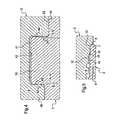
- FIG. 1diagrammatically shows a first threaded connection in longitudinal section
- FIG. 2diagrammatically shows a second threaded connection in longitudinal section
- FIG. 3diagrammatically shows a threaded zone of the connection in a longitudinal sectional half-view
- FIG. 4diagrammatically shows a detail of the threaded zone of the connection
- FIG. 5diagrammatically shows one end of the male portion.
- sealing surfacesmay be provided adjacent to the threaded zones, said surfaces being brought into interfering contact when threading-up the components.
- the threaded zonesare provided at the end of each of the male and female tubular components.
- the female tubular componentmay be a great length tube or, in contrast, a short coupling type tube.
- the tightness to high pressure fluidsthus results from bringing the sealing surfaces into mutual radially interfering contact.
- the intensity of the radial interfering contactis a function of the relative axial positioning of the male and female threaded zones, said relative positioning being determined by contact of the abutment surfaces provided respectively on the male and female ends.
- the relative positioningresults from contact of the abutments.
- the abutment surfacesare provided on the internal surface of the connection.
- the male endcomprises a threaded zone extended by a sealing surface which is itself extended by a terminal portion finishing in an abutment surface which is orientated radially with respect to the axis of revolution of the connection.
- the female endcomprises a threaded zone extended by a sealing surface which is itself extended by a terminal portion finishing in an abutment surface which is orientated radially with respect to the axis of revolution of the connection.
- the connectionthus has a double abutment.
- Other connectionshave a single abutment, radially externally of the threaded zone or internally of the threaded zone.
- the Applicanthas particularly focused on large diameter threaded connections with a diameter of more than 300 mm, more particularly more than 375 mm. Such connections are occasionally subjected to intense tensile and compressive loads. Thus, it is desirable that the connection performs well under tension and in compression. When the tensile load is excessive, the threads can separate from each other by a disengaging phenomenon which causes the two components of the connection to separate. The consequences can be particularly annoying from a technical and cost viewpoint. This is particularly the case when the threading has a tapered generatrix; jump-out of a thread can cause the connection to come apart completely.
- U.S. Pat. No. 4,822,081describes a threading for male and female connections used in oil exploration tubes.
- the threadsare of the self-locking type with contact between the flanks when the shoulders and the end surfaces are just in contact.
- the abutment surfacesare tapered at different angles.
- the threadsare also self-clinching in the radial direction. That type of self-locking and self-clinching threaded connection necessitates a very high makeup torque which is difficult to achieve for large diameter tubes.
- the free volume in the threadingbeing very low, the threading-up may cause the grease to come under a high pressure, which may cause leaks.
- the axial positions of the abutment surfaces with respect to the threadsbeing uncertain because of the industrial tolerances, there may result a poor positioning of the sealing surfaces and consequently a leak.
- the end of the threading-up operationis barely capable of being detected by determination of an upper limit to the torque, due to the absence of a positive abutment during threading-up.
- the abutmentsare reached during final makeup.
- An excessive threading-up torquemay result in plastic deformation of the sealing surfaces, which deleteriously affects the seal of the connection.
- the document JP 2002/081584discloses a thread profile with hook cooperation. Those hooks support all of the tensile loads and radial displacement loads, which may cause damage to the threads with repetitive, cyclic forces. The tensile loads must remain low due to the small surface area via which they are transmitted. The stabbing flanks are steeply inclined, which is deleterious to compressive strength. A high threading-up torque is necessary because of the interference between the thread crests and valleys.
- the Applicanthas developed a connection which greatly reduces the risk of jump-out independently of the position of the thread, at a low threading-up torque, which allows the bearing surfaces to be properly positioned and has sufficient space for grease.
- the threadinghas a variable thread width.
- An axial clearance between the stabbing flanksis present in the connected state, i.e. after makeup, and also there is a radial clearance present between the thread roots and crests.
- the load flanks of the threadsare at a negative angle.
- the stabbing flanks of the threadsare at a positive angle.
- An abutmentallows proper positioning of the sealing surfaces.
- a threaded tubular connection 1comprises a female end 2 and a male end 3 .
- the female end 2 and/or the male end 3may belong to a tube several meters in length, for example of the order of 10 to 15 meters long.
- One end, generally female,may constitute the end of a coupling, in other words a short length tube enabling to connect together two great length tubes each provided with two male ends (threaded and coupled connection known as T&C connection).
- a couplingmay be provided with two female ends.
- a great length tubemay be provided with one male end and one female end (integral threaded connection).
- the connection 1is of the industrially mass produced type.
- connection 1may be used to constitute casing strings or tubing strings for hydrocarbon wells, or work-over risers or drillpipe strings for the same wells.
- the tubesmay be produced in different types of non-alloyed, low alloy or high alloy steel, or even in ferrous or non-ferrous alloys, which are heat treated or cold-worked depending on their service conditions, such as, for example: the level of mechanical stress, the corrosive nature of the fluid inside or outside the tubes, etc. It is also possible to use low corrosion resistance steel tubes coated with a protective coating, for example an alloy which is resistant to corrosion or a synthetic material.
- the threaded female end 2comprises a female threaded zone 4 .
- the female threaded zone 4is tapered, for example with a half-angle in the range 0.5° to 3°, preferably in the range 1° to 2°.
- the female threaded zone 4is disposed on the inside of the female element 2 .
- the male end 3comprises a male threaded zone 5 disposed on an external surface of said male end 3 .
- the male threaded zone 5mates with the female threading 4 .
- the male threaded zone 5has a taper which is substantially equal to that of the female threaded zone 4 .
- the female end 2comprises a distal surface 6 which is substantially perpendicular to the axis 20 of the connection.
- distal surfacemeans a surface situated between a threaded zone, continuous or discontinuous, and the free end of the element, male or female. A distal surface may be located at said free end. In this case, the distal surface 6 is terminal.
- the female threaded zone 4extends up to adjacent to the terminal surface 6 .
- the terminal surface 6is separated from any optional substantially radial surface of the male end 3 , in particular a shoulder, by at least 0.1 mm, for example.
- the distal surface of the male end 3is in the form of an annular surface, in this case tapered.
- the distal surfaceform an axial abutment surface 7 which enables to limit relative axial movement between the female end 2 and the male end 3 .
- the abutment surface 7is in contact against a shoulder of the female end 2 also forming an abutment surface 8 , in this case tapered.
- the abutment surface 7may be radial or inclined at an angle of up to 45° with respect to a radial plane. In the example shown in FIG. 1 , the angle is of the order of 15° to 25°.
- the female endcomprises a substantially tapered surface 12 and optionally a recess 10 , see FIG. 5 .
- the recess 10may have a substantially cylindrical surface 14 and a surface of revolution 18 disposed between the threaded zone 4 and the substantially tapered surface 12 .
- the substantially tapered surface 12is adjacent to the abutment surface 8 .
- the recess 10may act as a reservoir for grease when grease is expelled from between the threaded zones 4 and 5 , on threading-up.
- at least one hollow of the threaded zone 4 adjacent to the substantially cylindrical surface 14is free in the connected state and participates in collecting excess grease.
- the surface of revolution 18connects the substantially cylindrical surface 14 to the abutment surface 8 .
- the abutment surface 8may have a tapered shape as in document EP-0 488 912, a toroidal shape as in document U.S. Pat. No. 3,870,351 or in WO-2007/017082, or multi-stage as in document U.S. Pat. No. 4,611,838, with a protuberance as in document U.S. Pat. No. 6,047,797, or a combination of those shapes. The reader is invited to refer to these documents.
- the male end 3comprises a lip 9 extending axially beyond the male threaded zone 5 up to the abutment surface 7 .
- the outside of the lip 9comprises a substantially tapered surface 13 with an axial length slightly longer than the axial length of the surface of revolution 12 , which is substantially tapered, of the female end 2 .
- a portion of the surface of revolution 13 and a portion of the surface of revolution 12are in mutual radially interfering contact in the connected position of the connection 1 illustrated in the figures.
- the surfaces of revolution 12 and 13 forming the sealing surfacesenable to prevent the movement of fluid between the inside and the outside of the connection.
- the angle of taper of the sealing surfacesmay be in the range 1° to 45°, preferably in the range 3° to 20°, for example 6°.
- the angle of taper of the sealing surfacesmay be greater than the angle of taper of the threaded zones.
- the connectioncomprises an axial abutment which ensures precise positioning of the sealing zone formed by the surfaces of revolution 12 and 13 in the connected
- FIG. 2The embodiment of FIG. 2 is similar to the preceding embodiment, with the exception that the abutment surfaces 7 and 8 of the female 2 and male 3 ends are disposed on the radially external side of the connection.
- the abutment surfaces 7 and 8are disposed between the female 4 and male 5 threaded zones and the external surface of the connection 1 .
- the female end 2comprises a sealing surface 12 adjacent to the abutment surface 8 and a sealing surface 14 distal to the abutment surface 8 .
- the sealing surface 14is disposed between the female threaded zone 4 and the bore of the female end 2 .
- the sealing surface 14is substantially tapered, for example at an angle in the range 1° to 45°.
- the sealing surface 12is domed and annular, for example a circular arc in axial section.
- the male end 3comprises a sealing surface 13 adjacent to the abutment surface 7 and a sealing surface 15 distal to the abutment surface 7 .
- the sealing surface 13is in tight contact with the sealing surface 12 in the connected or made up state.
- the sealing surface 15is disposed between the male threaded zone 5 and the bore of the male end 3 .
- the sealing surface 15is substantially tapered, for example at an angle in the range 1° to 45°. The angle of the sealing surface 15 is smaller than the angle of the sealing surface 14 .
- the sealing surface 15is in tight contact with the sealing surface 14 in the connected or made up state.
- the lip 9 of the male end 3comprises a substantially radial terminal surface 17 extending between the sealing surface 15 and the bore of the male end 3 .
- the terminal surface 17may have a radial dimension in the range 0.5 mm to 16 mm depending on the diameter of the tube which itself may be up to 550 mm, while preferably being more than 300 mm, more preferably 350 mm.
- the terminal surface 17is distant from any substantially radial surface of the female end 2 by at least 0.1 mm, for example.
- the connectioncomprises an axial abutment which provides precise positioning of the two sealing zones formed by the sealing surfaces 12 and 13 on the one hand and 14 and 15 on the other hand in the connected state.
- the female threaded zone 4comprises threads 40 with an axial length adjacent to the crest which is greater than the axial length adjacent to the base.
- the male threaded zone 5comprises threads 50 with an axial length adjacent to the crest which is greater than the axial length adjacent to the base.
- the angle of inclination of a stabbing flank of one threadis positive in the clockwise direction, the angle being measured with respect to a radial plane perpendicular to the axis of the connection.
- the angle of inclination of a load flank of a threadis negative in the clockwise direction, the angle being taken with respect to a radial plane perpendicular to the axis of the connection.
- the threads 40 , 50have a dovetail profile.
- the angle of inclination of a load flankis different from the angle of inclination of a stabbing flank.
- the angle of inclination of a stabbing flank of the female threaded zone 4is substantially equal to the angle of inclination of a stabbing flank of the male threaded zone 5 .
- the angle of inclination of a load flank of the female threaded zone 4is substantially equal to the angle of inclination of a load flank of the male threaded zone 5 .
- a thread 40 , 50comprises a crest 41 , 51 , a root 42 , 52 , a load flank 43 , 53 and a stabbing flank 44 , 54 .
- Connection curvaturesare provided between the flanks and crest and between the flanks and root.
- the diameter of the crests 41 , 51 and the roots 42 , 52varies as a function of the position of the corresponding thread along the axis of the tube due to the taper of the threading.
- the crests 41 , 51 and the roots 42 , 52 of the threads 40 , 50are parallel to the axis of the threaded connection. This facilitates machining and engagement during threading-up.
- the male threaded zone 5may have a first portion in which the width of its teeth increases from a value corresponding to the width of the tooth closest to the terminal surface of the male end to a value corresponding to the width of the tooth furthest from said terminal surface, while the width of the teeth of the female threaded zone 4 decreases from a value corresponding to the width of the tooth furthest from the terminal surface of the female end to a value corresponding to the width of the tooth closest to said terminal surface, such that the threaded zones 4 , 5 cooperate on threading-up to leave an axial clearance between the stabbing flanks.
- the ratio between the width of the tooth closest to the terminal surface of the male end and the width of the tooth furthest from the terminal surface of the female endmay be in the range 0.1 to 0.8.
- a radial clearanceis present between the crests 41 of the threads 40 of the female threaded zone 4 and the roots 52 of the threads 50 of the male threaded zone 5 .
- the radial clearanceis of the order of 0.05 mm to 0.5 mm.
- the choice of radial clearance in the connected statemay be guided by the desired volume of grease and the machining tolerances. A clearance of 0.15 mm or less is desirable when the machining quality is high.
- a radial clearancewhich is visible in FIG. 4 , is present between the roots 42 of the threads 40 and the crests 51 of the threads 50 .
- the radial clearanceis of the order of 0.05 mm to 0.5 mm.
- an axial clearancevisible in FIG. 4 , is present between the stabbing flanks 44 and 54 respectively of the threads 40 of the female threaded zone 4 and the threads 50 of the male threaded zone 5 .
- the axial clearanceis of the order of 0.002 mm to 1 mm.
- the choice of axial clearance in the connected statemay be guided by the desired volume of grease, the angle of the flanks and the machining tolerances.
- a clearance of 0.05 mm or lessis desirable when high quality machining is carried out and the angle of the flanks has an absolute value of 5° or less.
- the load flanks 43 and 53take up the interfering loads after make-up.
- the load flank 43 of the threads 40 of the female threaded zone 4is inclined with respect to a radial plane in order to interfere with the corresponding inclined load flank 53 of the threads 50 of the male threaded zone 5 in the case of elastic deformation of the connection, in particular under tension, with or without internal pressure.
- the interferenceis radial in order to preserve the linkage between the threadings.
- the threadingsmutually form radial retaining hooks.
- the inclination of the load flank 43is in the range ⁇ 1° to ⁇ 15°. Above ⁇ 1°, the radial retention effect becomes low. Below ⁇ 15°, the compressive strength may be affected. A preferred range is from ⁇ 3° to ⁇ 5°.
- the inclination of the load flank 53 of the threads 50 of the male threaded zone 5is located in the same principal preferred ranges.
- the inclination of the load flank 53may be equal to or different from the inclination of the load flank 43 , for example by approximately 3°.
- the stabbing flank 44 of the threads 40 of the female threaded zone 4is inclined with respect to a radial plane in order to interfere with the corresponding inclined stabbing flank 54 of the threads 50 of the male threaded zone 5 in the case of elastic deformation of the connection, in particular under tensile load, with or without internal pressure.
- the interferenceis radial in order to preserve the linkage between the threadings.
- the threadingsmutually form radial retaining hooks.
- the inclination of the stabbing flank 44is in the range 1° to 15°. Below 1°, the radial retention effect becomes low. Above 15°, the compressive strength may be affected. A preferred range is from 3° to 5°.
- the inclination of the stabbing flank 54 of the threads 50 of the male threaded zone 5is located in the same principal preferred ranges.
- the inclination of the stabbing flank 54may be equal to or different from the inclination of the stabbing flank 44 , for example by approximately 3°.
- the inclination of the stabbing flank 44may be equal to or different from the inclination of the load flank 43 , for example by approximately 3°.
- the inclination of the stabbing flank 54may be equal to or different from the inclination of the load flank 53 , for example by approximately 3°.
- the connecting curvaturesmay be in the range 0.005 mm to 3 mm.
- the connecting curvaturesreduce the concentration of stresses at the foot of the load flanks and thus improve the fatigue behaviour of the connection.
- the female 4 and male 5 threaded zonesmay constitute multiple-start threads, preferably a dual-start thread. This makes threading-up faster.
- the flanksmay have a dovetail profile.
- the geometry of dovetail threadsincreases the radial rigidity when they are connected, compared threads with an axial width which reduces steadily from the base to the crest of the threads.
- the flanksmay have a trapezoidal profile.
- the axial clearance between the stabbing flanksmay be in the range 0.002 mm to 1 mm, preferably in the range 0.05 mm to 0.5 mm.
- the radial clearancemay be provided at the thread roots of a first component and/or at the thread crests of a first component.
- the radial clearancemay be in the range 0.05 mm to 0.5 mm, preferably in the range 0.05 mm to 0.15 mm.
- the load flanksmay be at angle in the range ⁇ 1° to ⁇ 15°, preferably in the range ⁇ 3° to ⁇ 5°.
- the stabbing flanksmay be at an angle in the range 1° to 15°, preferably in the range 3° to 5°.
- the load flanksmay beat a different angle from the stabbing flanks.
- the abutment surfaces in mutual contact-may be at an angle in the range 0° to 45°, preferably in the range 5° to 20°, with respect to a radial plane.
- the threaded zonesmay constitute multiple-start threads, such as dual-start threads, for example.
- the male endmay comprise between its distal surface and its threaded zone ( 5 ), a metal/metal sealing surface cooperating with a corresponding sealing surface provided on the female end.
- the female endmay comprise between its distal surface and its threaded zone ( 6 ), a metal/metal sealing surface cooperating with a corresponding sealing surface provided on the male end.
- the threaded zonesmay have a taper generatrix with a slope in the range 4% to 15%.
Landscapes
- Engineering & Computer Science (AREA)
- General Engineering & Computer Science (AREA)
- Mechanical Engineering (AREA)
- Geology (AREA)
- Life Sciences & Earth Sciences (AREA)
- Mining & Mineral Resources (AREA)
- Environmental & Geological Engineering (AREA)
- Fluid Mechanics (AREA)
- General Life Sciences & Earth Sciences (AREA)
- Geochemistry & Mineralogy (AREA)
- Physics & Mathematics (AREA)
- Non-Disconnectible Joints And Screw-Threaded Joints (AREA)
- Earth Drilling (AREA)
- Mutual Connection Of Rods And Tubes (AREA)
- Joints With Pressure Members (AREA)
Abstract
Description
L=L0+Ax,
in which L0and A are constants and x is the position along the axis. The width is measured parallel to the axis of the connection1. The diameter of the
Claims (18)
Applications Claiming Priority (3)
| Application Number | Priority Date | Filing Date | Title |
|---|---|---|---|
| FR0905586AFR2952993B1 (en) | 2009-11-20 | 2009-11-20 | THREADED JOINT |
| FR0905586 | 2009-11-20 | ||
| PCT/EP2010/006823WO2011060894A2 (en) | 2009-11-20 | 2010-11-09 | Threaded connection |
Publications (2)
| Publication Number | Publication Date |
|---|---|
| US20130069364A1 US20130069364A1 (en) | 2013-03-21 |
| US9273521B2true US9273521B2 (en) | 2016-03-01 |
Family
ID=42751997
Family Applications (1)
| Application Number | Title | Priority Date | Filing Date |
|---|---|---|---|
| US13/510,697Active2033-03-21US9273521B2 (en) | 2009-11-20 | 2010-11-09 | Threaded connection |
Country Status (15)
| Country | Link |
|---|---|
| US (1) | US9273521B2 (en) |
| EP (1) | EP2501974B1 (en) |
| JP (1) | JP2013511672A (en) |
| CN (1) | CN102639911B (en) |
| AR (1) | AR079110A1 (en) |
| AU (1) | AU2010321285B2 (en) |
| BR (1) | BR112012012134B1 (en) |
| CA (1) | CA2781271C (en) |
| EA (1) | EA021456B1 (en) |
| FR (1) | FR2952993B1 (en) |
| MX (1) | MX337725B (en) |
| MY (1) | MY164357A (en) |
| PL (1) | PL2501974T3 (en) |
| UA (1) | UA110101C2 (en) |
| WO (1) | WO2011060894A2 (en) |
Cited By (4)
| Publication number | Priority date | Publication date | Assignee | Title |
|---|---|---|---|---|
| US10612702B2 (en) | 2017-03-03 | 2020-04-07 | Arcelormittal Tubular Products Luxembourg S.A. | Torque shoulder of a premium connection |
| US10612700B2 (en) | 2015-02-19 | 2020-04-07 | Arcelormittal Tubular Products Luxembourg S.A. | Method for making a threaded connection for pipes, such as oil and gas pipes |
| WO2020092194A1 (en)* | 2018-10-29 | 2020-05-07 | Dril-Quip, Inc. | Threaded connector having metal-to-metal seal |
| EP3835541A1 (en) | 2019-12-13 | 2021-06-16 | Vallourec Oil And Gas France | Threaded connection partially in a self-locking engagement with an external shoulder capable to resist elevated torque |
Families Citing this family (24)
| Publication number | Priority date | Publication date | Assignee | Title |
|---|---|---|---|---|
| US9850723B2 (en) | 2011-01-26 | 2017-12-26 | Bly Ip Inc. | Drill string components having multiple-thread joints |
| US9810029B2 (en) | 2011-01-26 | 2017-11-07 | Bly Ip Inc. | Drill string components resistant to jamming |
| US10557316B2 (en) | 2011-01-26 | 2020-02-11 | Bly Ip Inc. | Drill string components having multiple-thread joints |
| US20160186899A1 (en)* | 2011-08-05 | 2016-06-30 | Vallourec Oil And Gas France | Tubular connection with self-locking thread form used in the oil industry |
| CA2973262C (en)* | 2012-09-13 | 2020-06-30 | Bly Ip Inc. | Drill string components having multiple-thread joints |
| JP5803953B2 (en) | 2013-02-18 | 2015-11-04 | Jfeスチール株式会社 | Threaded joint for pipe connection |
| FR3006029B1 (en)* | 2013-05-23 | 2015-11-13 | Vallourec Mannesmann Oil & Gas | ASSEMBLY FOR THE PRODUCTION OF A THREADED JOINT FOR DRILLING AND OPERATING HYDROCARBON WELLS AND RESULTING THREAD |
| CN103291228B (en)* | 2013-06-07 | 2015-05-13 | 中国石油集团石油管工程技术研究院 | Machining method of oil casing special threads |
| FR3007495B1 (en)* | 2013-06-19 | 2015-11-13 | Vallourec Mannesmann Oil & Gas | ASSEMBLY FOR MAKING A THREADED JOINT FOR DRILLING AND OPERATING HYDROCARBON WELLS, THREADED JOINT AND METHOD OF MAKING SAME |
| FR3008763B1 (en)* | 2013-07-18 | 2015-07-31 | Vallourec Mannesmann Oil & Gas | ASSEMBLY FOR THE PRODUCTION OF A THREADED JOINT FOR DRILLING AND OPERATING HYDROCARBON WELLS AND RESULTING THREAD |
| CA2921411C (en) | 2013-09-06 | 2018-07-10 | Nippon Steel & Sumitomo Metal Corporation | Threaded connection for steel pipe |
| CA2961189C (en) | 2014-10-06 | 2020-02-18 | Nippon Steel & Sumitomo Metal Corporation | Threaded joint for steel pipes |
| FR3030668B1 (en)* | 2014-12-19 | 2016-12-16 | Vallourec Oil & Gas France | THREADED JOINT |
| US9683684B1 (en) | 2015-12-09 | 2017-06-20 | Certus Energy Solutions, Llc | Tubular coupling |
| US11466800B2 (en) | 2015-12-09 | 2022-10-11 | Certus Energy Solutions, Llc | Tubular coupling |
| US11047413B2 (en) | 2016-04-27 | 2021-06-29 | Hydril Company | Threaded and coupled tubular goods connection |
| RU168796U1 (en)* | 2016-06-24 | 2017-02-21 | Общество с ограниченной ответственностью "БИИКС" | Casing pipe reinforced |
| FR3060701A1 (en)* | 2016-12-16 | 2018-06-22 | Vallourec Oil And Gas France | THREADED SEAL FOR TUBULAR COMPONENT |
| EP3473798B2 (en) | 2017-10-20 | 2025-06-18 | Vallourec Oil And Gas France | Threaded connection partially in a self-locking engagement |
| US11774014B2 (en)* | 2018-08-24 | 2023-10-03 | Nippon Steel Corporation | Threaded connection for steel pipes |
| US11199056B2 (en)* | 2019-02-06 | 2021-12-14 | James Jing Yao | Threaded coupling for percussion drill bit |
| FR3098879B1 (en)* | 2019-07-19 | 2021-07-30 | Vallourec Oil & Gas France | Threaded joint with asymmetrical helical profile |
| FR3098878B1 (en)* | 2019-07-19 | 2021-07-30 | Vallourec Oil & Gas France | Threaded joint for oil well casing column |
| FR3121492B1 (en)* | 2021-03-31 | 2023-02-24 | Vallourec Oil & Gas France | Dimensioning of a thread axial clearance |
Citations (20)
| Publication number | Priority date | Publication date | Assignee | Title |
|---|---|---|---|---|
| US3870351A (en) | 1972-03-31 | 1975-03-11 | Sumitomo Metal Ind | Threaded tube joint structure for casing, particularly oil well tubing |
| USRE30647E (en)* | 1975-04-23 | 1981-06-16 | Hydril Company | Tubular connection |
| US4611838A (en) | 1982-02-27 | 1986-09-16 | Mannesmann Aktiengesellschaft | Fluidtight pipe joint |
| US4629222A (en)* | 1983-08-31 | 1986-12-16 | Hunting Oilfield Services (Uk) Limited | Pipe connector |
| US4822081A (en) | 1987-03-23 | 1989-04-18 | Xl Systems | Driveable threaded tubular connection |
| EP0488912A2 (en) | 1990-11-27 | 1992-06-03 | Vallourec Oil & Gas | Frustoconical screwthread for tubes |
| US5462315A (en) | 1992-03-09 | 1995-10-31 | Marubeni Tubulars, Inc. | Stabilized center-shoulder-sealed tubular connection |
| US6026436A (en)* | 1997-11-21 | 2000-02-15 | Xerox Corporation | System for cloning document processing related settings in a document processing system |
| US6047797A (en) | 1997-03-11 | 2000-04-11 | Fichtel & Sachs Industries, Inc. | Emergency locking gas spring |
| EP1046179A1 (en) | 1998-01-09 | 2000-10-25 | Florida International University | Optoelectronic device used to modulate the flow of electrons |
| US6155613A (en) | 1994-08-29 | 2000-12-05 | Mannesmann Aktiengesellschaft | Pipe joint |
| US6158785A (en)* | 1998-08-06 | 2000-12-12 | Hydril Company | Multi-start wedge thread for tubular connection |
| US20020027363A1 (en) | 1999-04-19 | 2002-03-07 | Mallis David Llewellyn | Wedge thread with torque shoulder |
| JP2002081584A (en) | 2000-09-08 | 2002-03-22 | Sumitomo Metal Ind Ltd | Pipe threaded fittings |
| US20040262919A1 (en)* | 2001-12-07 | 2004-12-30 | Pierre Dutilleul | Premium tubular threaded joint comprising at least a threaded element with end lip |
| US20060145480A1 (en)* | 2004-12-30 | 2006-07-06 | Hydril Company | Floating wedge thread for tubular connection |
| WO2007017082A1 (en) | 2005-08-09 | 2007-02-15 | Vallourec Mannesmann Oil & Gas France | Liquid and gas tight threaded tubular connection |
| US20070236015A1 (en)* | 2004-08-27 | 2007-10-11 | Masaaki Sugino | Threaded joint for steel pipes |
| CN201288903Y (en) | 2008-09-28 | 2009-08-12 | 上海海隆石油管材研究所 | Oil sleeve screwed connection head of negative bearing angle |
| US20110278838A1 (en) | 2008-12-16 | 2011-11-17 | Sumitomo Metal Industries, Ltd. | Tubular connection with self-locking threading used in the oil industry |
Family Cites Families (26)
| Publication number | Priority date | Publication date | Assignee | Title |
|---|---|---|---|---|
| US227363A (en) | 1880-05-11 | Ironing-board | ||
| US3989284A (en)* | 1975-04-23 | 1976-11-02 | Hydril Company | Tubular connection |
| DE2641767B2 (en)* | 1976-09-14 | 1979-05-31 | Mannesmann Ag, 4000 Duesseldorf | Threaded connection for oil field pipes |
| US4917409A (en) | 1983-04-29 | 1990-04-17 | Hydril Company | Tubular connection |
| WO1984004351A1 (en)* | 1983-04-29 | 1984-11-08 | Hydril Co | Improved tubular connection |
| US4946201A (en) | 1989-03-08 | 1990-08-07 | Baroid Technology, Inc. | Oil field tubular connection |
| GB9104271D0 (en)* | 1991-02-28 | 1991-04-17 | Hunting Oilfield Services Ltd | Improvements in and relating to pipe connectors |
| DE69532400T2 (en) | 1994-10-19 | 2004-11-11 | Vallourec Mannesmann Oil & Gas France | Threaded connection for pipes |
| US6174001B1 (en)* | 1998-03-19 | 2001-01-16 | Hydril Company | Two-step, low torque wedge thread for tubular connector |
| JP2000314490A (en)* | 1999-04-30 | 2000-11-14 | Kawasaki Steel Corp | Screw joints for oil country tubular goods |
| JP2001124253A (en)* | 1999-10-29 | 2001-05-11 | Kawasaki Steel Corp | Screw joints for steel pipes |
| JP2001173850A (en)* | 1999-12-22 | 2001-06-29 | Kawasaki Steel Corp | Fittings for steel pipes |
| US6442826B1 (en) | 2000-05-23 | 2002-09-03 | Hunting Oilfield Services, Inc. | Method for manufacturing a flush/semi-flush threaded connection |
| US6976711B2 (en)* | 2002-04-19 | 2005-12-20 | Hydril Company Lp | Threaded connection especially for radially plastically expandable conduit |
| ITRM20020274A1 (en) | 2002-05-16 | 2003-11-17 | Tenaris Connections Bv | THREADED JOINT FOR PIPES. |
| GB0221220D0 (en)* | 2002-09-13 | 2002-10-23 | Weatherford Lamb | Expanding coupling |
| US6893057B2 (en) | 2002-10-31 | 2005-05-17 | Grant Prideco, L.P. | Threaded pipe connection |
| US20070228729A1 (en) | 2003-03-06 | 2007-10-04 | Grimmett Harold M | Tubular goods with threaded integral joint connections |
| FR2855587B1 (en) | 2003-05-30 | 2006-12-29 | Vallourec Mannesmann Oil & Gas | TUBULAR THREADED JOINT WITH PROGRESSIVE AXIAL THREAD |
| UA82694C2 (en) | 2003-06-06 | 2008-05-12 | Sumitomo Metal Ind | Threaded joint for steel pipes |
| US20050116468A1 (en) | 2003-11-28 | 2005-06-02 | Otten Gregory K. | Threaded connectors for axial alignment of tubular components, and method of installing pipe sections employing such connectors |
| US20060071473A1 (en)* | 2004-10-05 | 2006-04-06 | Sivley Robert S Iv | Helical groove for a tubular connection |
| US7578039B2 (en) | 2004-11-05 | 2009-08-25 | Hydril Llc | Dope relief method for wedge thread connections |
| US7717478B2 (en) | 2006-08-29 | 2010-05-18 | Hydril Llc | Scalloped wedge threads |
| US7850211B2 (en) | 2006-01-24 | 2010-12-14 | Hydril Company | Wedge thread connections having a clearance gap volume |
| WO2009060552A1 (en)* | 2007-11-08 | 2009-05-14 | Sumitomo Metal Industries, Ltd. | Threaded joint for steel pipes |
- 2009
- 2009-11-20FRFR0905586Apatent/FR2952993B1/enactiveActive
- 2010
- 2010-09-11UAUAA201207525Apatent/UA110101C2/enunknown
- 2010-11-09BRBR112012012134-0Apatent/BR112012012134B1/enactiveIP Right Grant
- 2010-11-09CNCN201080052165.3Apatent/CN102639911B/enactiveActive
- 2010-11-09USUS13/510,697patent/US9273521B2/enactiveActive
- 2010-11-09JPJP2012539218Apatent/JP2013511672A/enactivePending
- 2010-11-09MXMX2012005796Apatent/MX337725B/enactiveIP Right Grant
- 2010-11-09AUAU2010321285Apatent/AU2010321285B2/enactiveActive
- 2010-11-09CACA2781271Apatent/CA2781271C/enactiveActive
- 2010-11-09WOPCT/EP2010/006823patent/WO2011060894A2/enactiveApplication Filing
- 2010-11-09MYMYPI2012002214Apatent/MY164357A/enunknown
- 2010-11-09PLPL10784259Tpatent/PL2501974T3/enunknown
- 2010-11-09EAEA201270635Apatent/EA021456B1/ennot_activeIP Right Cessation
- 2010-11-09EPEP10784259.3Apatent/EP2501974B1/ennot_activeRevoked
- 2010-11-19ARARP100104293Apatent/AR079110A1/enactiveIP Right Grant
Patent Citations (21)
| Publication number | Priority date | Publication date | Assignee | Title |
|---|---|---|---|---|
| US3870351A (en) | 1972-03-31 | 1975-03-11 | Sumitomo Metal Ind | Threaded tube joint structure for casing, particularly oil well tubing |
| USRE30647E (en)* | 1975-04-23 | 1981-06-16 | Hydril Company | Tubular connection |
| US4611838A (en) | 1982-02-27 | 1986-09-16 | Mannesmann Aktiengesellschaft | Fluidtight pipe joint |
| US4629222A (en)* | 1983-08-31 | 1986-12-16 | Hunting Oilfield Services (Uk) Limited | Pipe connector |
| US4822081A (en) | 1987-03-23 | 1989-04-18 | Xl Systems | Driveable threaded tubular connection |
| EP0488912A2 (en) | 1990-11-27 | 1992-06-03 | Vallourec Oil & Gas | Frustoconical screwthread for tubes |
| US5462315A (en) | 1992-03-09 | 1995-10-31 | Marubeni Tubulars, Inc. | Stabilized center-shoulder-sealed tubular connection |
| US6155613A (en) | 1994-08-29 | 2000-12-05 | Mannesmann Aktiengesellschaft | Pipe joint |
| US6047797A (en) | 1997-03-11 | 2000-04-11 | Fichtel & Sachs Industries, Inc. | Emergency locking gas spring |
| US6026436A (en)* | 1997-11-21 | 2000-02-15 | Xerox Corporation | System for cloning document processing related settings in a document processing system |
| EP1046179A1 (en) | 1998-01-09 | 2000-10-25 | Florida International University | Optoelectronic device used to modulate the flow of electrons |
| US6158785A (en)* | 1998-08-06 | 2000-12-12 | Hydril Company | Multi-start wedge thread for tubular connection |
| US20020027363A1 (en) | 1999-04-19 | 2002-03-07 | Mallis David Llewellyn | Wedge thread with torque shoulder |
| JP2002081584A (en) | 2000-09-08 | 2002-03-22 | Sumitomo Metal Ind Ltd | Pipe threaded fittings |
| EP1302623A1 (en) | 2001-10-15 | 2003-04-16 | Hydril Company | Wedge thread with torque shoulder |
| US20040262919A1 (en)* | 2001-12-07 | 2004-12-30 | Pierre Dutilleul | Premium tubular threaded joint comprising at least a threaded element with end lip |
| US20070236015A1 (en)* | 2004-08-27 | 2007-10-11 | Masaaki Sugino | Threaded joint for steel pipes |
| US20060145480A1 (en)* | 2004-12-30 | 2006-07-06 | Hydril Company | Floating wedge thread for tubular connection |
| WO2007017082A1 (en) | 2005-08-09 | 2007-02-15 | Vallourec Mannesmann Oil & Gas France | Liquid and gas tight threaded tubular connection |
| CN201288903Y (en) | 2008-09-28 | 2009-08-12 | 上海海隆石油管材研究所 | Oil sleeve screwed connection head of negative bearing angle |
| US20110278838A1 (en) | 2008-12-16 | 2011-11-17 | Sumitomo Metal Industries, Ltd. | Tubular connection with self-locking threading used in the oil industry |
Non-Patent Citations (1)
| Title |
|---|
| International Search Report Issued Sep. 5, 2011 in PCT/EP10/06823 Filed Nov. 9, 2010. |
Cited By (9)
| Publication number | Priority date | Publication date | Assignee | Title |
|---|---|---|---|---|
| US10612700B2 (en) | 2015-02-19 | 2020-04-07 | Arcelormittal Tubular Products Luxembourg S.A. | Method for making a threaded connection for pipes, such as oil and gas pipes |
| US11614184B2 (en) | 2015-02-19 | 2023-03-28 | Arcelormittal Tubular Products Luxembourg S.A. | Method for making a threaded connection for pipes, such as oil and gas pipes |
| US10612702B2 (en) | 2017-03-03 | 2020-04-07 | Arcelormittal Tubular Products Luxembourg S.A. | Torque shoulder of a premium connection |
| US12104720B2 (en) | 2017-03-03 | 2024-10-01 | Arcelormittal Tubular Products Luxembourg S.A. | Torque shoulder of a premium connection |
| WO2020092194A1 (en)* | 2018-10-29 | 2020-05-07 | Dril-Quip, Inc. | Threaded connector having metal-to-metal seal |
| GB2591051A (en)* | 2018-10-29 | 2021-07-14 | Dril Quip Inc | Threaded connector having metal-to-metal seal |
| GB2591051B (en)* | 2018-10-29 | 2023-03-01 | Dril Quip Inc | Threaded connector having metal-to-metal seal |
| EP3835541A1 (en) | 2019-12-13 | 2021-06-16 | Vallourec Oil And Gas France | Threaded connection partially in a self-locking engagement with an external shoulder capable to resist elevated torque |
| WO2021116264A1 (en) | 2019-12-13 | 2021-06-17 | Vallourec Oil And Gas France | Threaded connection partially in a self-locking engagement with an external shoulder capable to resist elevated torque |
Also Published As
| Publication number | Publication date |
|---|---|
| BR112012012134B1 (en) | 2020-12-29 |
| MX337725B (en) | 2016-03-15 |
| EP2501974A2 (en) | 2012-09-26 |
| AU2010321285A1 (en) | 2012-05-24 |
| CN102639911A (en) | 2012-08-15 |
| BR112012012134A2 (en) | 2016-04-12 |
| UA110101C2 (en) | 2015-11-25 |
| CA2781271A1 (en) | 2011-05-26 |
| WO2011060894A2 (en) | 2011-05-26 |
| PL2501974T3 (en) | 2016-08-31 |
| AU2010321285B2 (en) | 2016-11-17 |
| EP2501974B1 (en) | 2016-02-17 |
| WO2011060894A3 (en) | 2011-11-10 |
| MX2012005796A (en) | 2012-06-19 |
| EA021456B1 (en) | 2015-06-30 |
| AR079110A1 (en) | 2011-12-28 |
| CN102639911B (en) | 2016-01-06 |
| CA2781271C (en) | 2018-03-13 |
| FR2952993A1 (en) | 2011-05-27 |
| MY164357A (en) | 2017-12-15 |
| JP2013511672A (en) | 2013-04-04 |
| EA201270635A1 (en) | 2012-11-30 |
| US20130069364A1 (en) | 2013-03-21 |
| FR2952993B1 (en) | 2011-12-16 |
Similar Documents
| Publication | Publication Date | Title |
|---|---|---|
| US9273521B2 (en) | Threaded connection | |
| US8678448B2 (en) | Threaded connection | |
| US7331614B2 (en) | Tubular threaded joint with trapezoid threads having convex bulged thread surface | |
| US10407997B2 (en) | Threaded connection | |
| AU2002364980B2 (en) | Premium tubular threaded joint comprising at least a threaded element with end lip | |
| US6755447B2 (en) | Production riser connector | |
| CA2338956C (en) | Threaded and coupled connection for improved fatigue resistance | |
| US7513534B2 (en) | Fatigue-resistant threaded component for a tubular threaded joint | |
| RU2659932C2 (en) | Assembly for producing threaded connection for drilling and operating hydrocarbon wells and resulting threaded connection | |
| CN110382812B (en) | Threaded Fittings for Fittings | |
| OA18344A (en) | Threaded connection |
Legal Events
| Date | Code | Title | Description |
|---|---|---|---|
| AS | Assignment | Owner name:VALLOUREC MANNESMANN OIL & GAS FRANCE, FRANCE Free format text:ASSIGNMENT OF ASSIGNORS INTEREST;ASSIGNORS:MARTIN, PIERRE;MAILLON, BERTRAND;SIGNING DATES FROM 20120620 TO 20120621;REEL/FRAME:028460/0244 Owner name:SUMITOMO METAL INDUSTRIES, LTD., JAPAN Free format text:ASSIGNMENT OF ASSIGNORS INTEREST;ASSIGNORS:MARTIN, PIERRE;MAILLON, BERTRAND;SIGNING DATES FROM 20120620 TO 20120621;REEL/FRAME:028460/0244 | |
| AS | Assignment | Owner name:VALLOUREC OIL AND GAS FRANCE, FRANCE Free format text:CHANGE OF NAME;ASSIGNOR:VALLOUREC MANNESMANN OIL & GAS FRANCE;REEL/FRAME:032696/0146 Effective date:20131001 | |
| STCF | Information on status: patent grant | Free format text:PATENTED CASE | |
| AS | Assignment | Owner name:NIPPON STEEL CORPORATION, JAPAN Free format text:CHANGE OF NAME;ASSIGNOR:NIPPON STEEL & SUMITOMO METAL CORPORATION;REEL/FRAME:049257/0828 Effective date:20190401 | |
| MAFP | Maintenance fee payment | Free format text:PAYMENT OF MAINTENANCE FEE, 4TH YEAR, LARGE ENTITY (ORIGINAL EVENT CODE: M1551); ENTITY STATUS OF PATENT OWNER: LARGE ENTITY Year of fee payment:4 | |
| MAFP | Maintenance fee payment | Free format text:PAYMENT OF MAINTENANCE FEE, 8TH YEAR, LARGE ENTITY (ORIGINAL EVENT CODE: M1552); ENTITY STATUS OF PATENT OWNER: LARGE ENTITY Year of fee payment:8 |