US9272113B2 - Transporting liquid in a respiratory component - Google Patents
Transporting liquid in a respiratory componentDownload PDFInfo
- Publication number
- US9272113B2 US9272113B2US13/436,775US201213436775AUS9272113B2US 9272113 B2US9272113 B2US 9272113B2US 201213436775 AUS201213436775 AUS 201213436775AUS 9272113 B2US9272113 B2US 9272113B2
- Authority
- US
- United States
- Prior art keywords
- respiratory component
- respiratory
- component
- liquid
- region
- Prior art date
- Legal status (The legal status is an assumption and is not a legal conclusion. Google has not performed a legal analysis and makes no representation as to the accuracy of the status listed.)
- Active, expires
Links
Images


Classifications
- A—HUMAN NECESSITIES
- A61—MEDICAL OR VETERINARY SCIENCE; HYGIENE
- A61M—DEVICES FOR INTRODUCING MEDIA INTO, OR ONTO, THE BODY; DEVICES FOR TRANSDUCING BODY MEDIA OR FOR TAKING MEDIA FROM THE BODY; DEVICES FOR PRODUCING OR ENDING SLEEP OR STUPOR
- A61M16/00—Devices for influencing the respiratory system of patients by gas treatment, e.g. ventilators; Tracheal tubes
- A61M16/08—Bellows; Connecting tubes ; Water traps; Patient circuits
- A61M16/0808—Condensation traps
- A—HUMAN NECESSITIES
- A61—MEDICAL OR VETERINARY SCIENCE; HYGIENE
- A61M—DEVICES FOR INTRODUCING MEDIA INTO, OR ONTO, THE BODY; DEVICES FOR TRANSDUCING BODY MEDIA OR FOR TAKING MEDIA FROM THE BODY; DEVICES FOR PRODUCING OR ENDING SLEEP OR STUPOR
- A61M16/00—Devices for influencing the respiratory system of patients by gas treatment, e.g. ventilators; Tracheal tubes
- A61M16/08—Bellows; Connecting tubes ; Water traps; Patient circuits
- A—HUMAN NECESSITIES
- A61—MEDICAL OR VETERINARY SCIENCE; HYGIENE
- A61M—DEVICES FOR INTRODUCING MEDIA INTO, OR ONTO, THE BODY; DEVICES FOR TRANSDUCING BODY MEDIA OR FOR TAKING MEDIA FROM THE BODY; DEVICES FOR PRODUCING OR ENDING SLEEP OR STUPOR
- A61M16/00—Devices for influencing the respiratory system of patients by gas treatment, e.g. ventilators; Tracheal tubes
- A61M16/10—Preparation of respiratory gases or vapours
- A61M16/1045—Devices for humidifying or heating the inspired gas by using recovered moisture or heat from the expired gas
- A—HUMAN NECESSITIES
- A61—MEDICAL OR VETERINARY SCIENCE; HYGIENE
- A61M—DEVICES FOR INTRODUCING MEDIA INTO, OR ONTO, THE BODY; DEVICES FOR TRANSDUCING BODY MEDIA OR FOR TAKING MEDIA FROM THE BODY; DEVICES FOR PRODUCING OR ENDING SLEEP OR STUPOR
- A61M16/00—Devices for influencing the respiratory system of patients by gas treatment, e.g. ventilators; Tracheal tubes
- A61M16/10—Preparation of respiratory gases or vapours
- A61M16/105—Filters
- A—HUMAN NECESSITIES
- A61—MEDICAL OR VETERINARY SCIENCE; HYGIENE
- A61M—DEVICES FOR INTRODUCING MEDIA INTO, OR ONTO, THE BODY; DEVICES FOR TRANSDUCING BODY MEDIA OR FOR TAKING MEDIA FROM THE BODY; DEVICES FOR PRODUCING OR ENDING SLEEP OR STUPOR
- A61M16/00—Devices for influencing the respiratory system of patients by gas treatment, e.g. ventilators; Tracheal tubes
- A61M16/10—Preparation of respiratory gases or vapours
- A61M16/1075—Preparation of respiratory gases or vapours by influencing the temperature
- A—HUMAN NECESSITIES
- A61—MEDICAL OR VETERINARY SCIENCE; HYGIENE
- A61M—DEVICES FOR INTRODUCING MEDIA INTO, OR ONTO, THE BODY; DEVICES FOR TRANSDUCING BODY MEDIA OR FOR TAKING MEDIA FROM THE BODY; DEVICES FOR PRODUCING OR ENDING SLEEP OR STUPOR
- A61M11/00—Sprayers or atomisers specially adapted for therapeutic purposes
- A—HUMAN NECESSITIES
- A61—MEDICAL OR VETERINARY SCIENCE; HYGIENE
- A61M—DEVICES FOR INTRODUCING MEDIA INTO, OR ONTO, THE BODY; DEVICES FOR TRANSDUCING BODY MEDIA OR FOR TAKING MEDIA FROM THE BODY; DEVICES FOR PRODUCING OR ENDING SLEEP OR STUPOR
- A61M16/00—Devices for influencing the respiratory system of patients by gas treatment, e.g. ventilators; Tracheal tubes
- A61M16/0003—Accessories therefor, e.g. sensors, vibrators, negative pressure
- A61M16/0006—Accessories therefor, e.g. sensors, vibrators, negative pressure with means for creating vibrations in patients' airways
- A—HUMAN NECESSITIES
- A61—MEDICAL OR VETERINARY SCIENCE; HYGIENE
- A61M—DEVICES FOR INTRODUCING MEDIA INTO, OR ONTO, THE BODY; DEVICES FOR TRANSDUCING BODY MEDIA OR FOR TAKING MEDIA FROM THE BODY; DEVICES FOR PRODUCING OR ENDING SLEEP OR STUPOR
- A61M16/00—Devices for influencing the respiratory system of patients by gas treatment, e.g. ventilators; Tracheal tubes
- A61M16/04—Tracheal tubes
- A61M16/0465—Tracheostomy tubes; Devices for performing a tracheostomy; Accessories therefor, e.g. masks, filters
- A—HUMAN NECESSITIES
- A61—MEDICAL OR VETERINARY SCIENCE; HYGIENE
- A61M—DEVICES FOR INTRODUCING MEDIA INTO, OR ONTO, THE BODY; DEVICES FOR TRANSDUCING BODY MEDIA OR FOR TAKING MEDIA FROM THE BODY; DEVICES FOR PRODUCING OR ENDING SLEEP OR STUPOR
- A61M16/00—Devices for influencing the respiratory system of patients by gas treatment, e.g. ventilators; Tracheal tubes
- A61M16/06—Respiratory or anaesthetic masks
- A61M16/0666—Nasal cannulas or tubing
- A—HUMAN NECESSITIES
- A61—MEDICAL OR VETERINARY SCIENCE; HYGIENE
- A61M—DEVICES FOR INTRODUCING MEDIA INTO, OR ONTO, THE BODY; DEVICES FOR TRANSDUCING BODY MEDIA OR FOR TAKING MEDIA FROM THE BODY; DEVICES FOR PRODUCING OR ENDING SLEEP OR STUPOR
- A61M16/00—Devices for influencing the respiratory system of patients by gas treatment, e.g. ventilators; Tracheal tubes
- A61M16/08—Bellows; Connecting tubes ; Water traps; Patient circuits
- A61M16/0875—Connecting tubes
- A—HUMAN NECESSITIES
- A61—MEDICAL OR VETERINARY SCIENCE; HYGIENE
- A61M—DEVICES FOR INTRODUCING MEDIA INTO, OR ONTO, THE BODY; DEVICES FOR TRANSDUCING BODY MEDIA OR FOR TAKING MEDIA FROM THE BODY; DEVICES FOR PRODUCING OR ENDING SLEEP OR STUPOR
- A61M16/00—Devices for influencing the respiratory system of patients by gas treatment, e.g. ventilators; Tracheal tubes
- A61M16/10—Preparation of respiratory gases or vapours
- A61M16/1075—Preparation of respiratory gases or vapours by influencing the temperature
- A61M16/1095—Preparation of respiratory gases or vapours by influencing the temperature in the connecting tubes
- A—HUMAN NECESSITIES
- A61—MEDICAL OR VETERINARY SCIENCE; HYGIENE
- A61M—DEVICES FOR INTRODUCING MEDIA INTO, OR ONTO, THE BODY; DEVICES FOR TRANSDUCING BODY MEDIA OR FOR TAKING MEDIA FROM THE BODY; DEVICES FOR PRODUCING OR ENDING SLEEP OR STUPOR
- A61M16/00—Devices for influencing the respiratory system of patients by gas treatment, e.g. ventilators; Tracheal tubes
- A61M16/10—Preparation of respiratory gases or vapours
- A61M16/14—Preparation of respiratory gases or vapours by mixing different fluids, one of them being in a liquid phase
- A61M16/16—Devices to humidify the respiration air
- A—HUMAN NECESSITIES
- A61—MEDICAL OR VETERINARY SCIENCE; HYGIENE
- A61M—DEVICES FOR INTRODUCING MEDIA INTO, OR ONTO, THE BODY; DEVICES FOR TRANSDUCING BODY MEDIA OR FOR TAKING MEDIA FROM THE BODY; DEVICES FOR PRODUCING OR ENDING SLEEP OR STUPOR
- A61M2205/00—General characteristics of the apparatus
- A61M2205/02—General characteristics of the apparatus characterised by a particular materials
- A61M2205/0227—Materials having sensing or indicating function, e.g. indicating a pressure increase
- A—HUMAN NECESSITIES
- A61—MEDICAL OR VETERINARY SCIENCE; HYGIENE
- A61M—DEVICES FOR INTRODUCING MEDIA INTO, OR ONTO, THE BODY; DEVICES FOR TRANSDUCING BODY MEDIA OR FOR TAKING MEDIA FROM THE BODY; DEVICES FOR PRODUCING OR ENDING SLEEP OR STUPOR
- A61M2205/00—General characteristics of the apparatus
- A61M2205/18—General characteristics of the apparatus with alarm
- A—HUMAN NECESSITIES
- A61—MEDICAL OR VETERINARY SCIENCE; HYGIENE
- A61M—DEVICES FOR INTRODUCING MEDIA INTO, OR ONTO, THE BODY; DEVICES FOR TRANSDUCING BODY MEDIA OR FOR TAKING MEDIA FROM THE BODY; DEVICES FOR PRODUCING OR ENDING SLEEP OR STUPOR
- A61M2205/00—General characteristics of the apparatus
- A61M2205/75—General characteristics of the apparatus with filters
- A61M2205/7527—General characteristics of the apparatus with filters liquophilic, hydrophilic
- A—HUMAN NECESSITIES
- A61—MEDICAL OR VETERINARY SCIENCE; HYGIENE
- A61M—DEVICES FOR INTRODUCING MEDIA INTO, OR ONTO, THE BODY; DEVICES FOR TRANSDUCING BODY MEDIA OR FOR TAKING MEDIA FROM THE BODY; DEVICES FOR PRODUCING OR ENDING SLEEP OR STUPOR
- A61M2207/00—Methods of manufacture, assembly or production
- F—MECHANICAL ENGINEERING; LIGHTING; HEATING; WEAPONS; BLASTING
- F04—POSITIVE - DISPLACEMENT MACHINES FOR LIQUIDS; PUMPS FOR LIQUIDS OR ELASTIC FLUIDS
- F04C—ROTARY-PISTON, OR OSCILLATING-PISTON, POSITIVE-DISPLACEMENT MACHINES FOR LIQUIDS; ROTARY-PISTON, OR OSCILLATING-PISTON, POSITIVE-DISPLACEMENT PUMPS
- F04C2270/00—Control; Monitoring or safety arrangements
- F04C2270/04—Force
- F04C2270/042—Force radial
- F04C2270/0421—Controlled or regulated
Definitions
- the present technologyrelates generally to the respiratory field. More particularly, the present technology relates to humidification.
- Respiratory humidification systemsare used in providing respiratory therapy to a patient.
- the systemincludes a ventilator, humidifier and patient circuit.
- the ventilatorsupplies gases to a humidification chamber coupled with the humidifier. Water within the humidification chamber is heated by the humidifier, which produces water vapor that humidifies gases within the chamber. From the chamber, humidified gases are then carried to the patient through the patient circuit.
- FIG. 1shows a block diagram of a respiratory component, coupled with a breathing circuit, with at least one groove disposed thereon, in accordance with an embodiment.
- FIG. 2shows a block diagram of a cross-sectional view of a respiratory component, coupled with a breathing circuit, with at least one groove disposed thereon, in accordance with an embodiment.
- FIG. 3shows a diagram of a respiratory component surrounded by and not a part of a heater wire, in accordance with an embodiment.
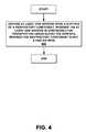
- FIG. 4is a flow diagram of an example method for manufacturing a device for transporting liquid along a surface within a respiratory component, in accordance with an embodiment.
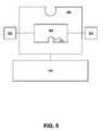
- FIG. 5shows a block diagram of a cross-sectional view of a liquid transporting device, coupled with a breathing circuit, in accordance with an embodiment.
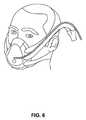
- FIG. 6shows a front perspective view of a patient breathing through a respiratory mask through the upper airways.
- FIG. 7shows a patient breathing with an endotracheal tube, wherein the patient's upper airways are bypassed.
- FIG. 8shows a flow diagram of a flow of gas during single limb ventilation.
- FIG. 9shows a flow diagram of a flow of gas during dual limb ventilation.
- Traditional humidification systems for respiratory gas delivery in critical care and patient care settingstypically involve a chamber of hot water which is used to provide vapor for humidifying the delivered gases.
- the method for heating this water bathis most often contact heating using a hot-plate or heating element which transfers heat to the water through a metallic surface which is incorporated into the humidification chamber.
- Embodimentsprovide a method and device for at least one or more of the following: transporting liquid in a respiratory component from a first location to a second location; removing condensation from a humidification component; moving liquid (from condensation regions) to heated (hotter) regions for evaporation; moving liquid (from condensation regions) to regions for indication (e.g. indication by chemical reaction); and creating additional surface area for evaporation of liquids to address the problem associated with humidifying liquids within a small volume.
- the humidification component described hereinis a structure that retains a fluid therein for humidifying.
- the humidification component described hereinsimply refers to the presence of moisture provided.
- non-invasive single limb ventilationdual-limb invasive ventilation, dual-limb non-invasive ventilation, continuous positive airway pressure (CPAP), bubble CPAP, bi-level positive airway pressure (BiPAP), intermittent positive pressure (IPPB), bland aerosol therapy and oxygen therapy.
- CPAPcontinuous positive airway pressure
- BiPAPbi-level positive airway pressure
- IPPBintermittent positive pressure
- non-invasive single and dual-limb ventilationrefers to the delivery of ventilator support using a mechanical ventilator, with one or multiple limbs, connected to a mask or mouthpiece instead of an endotracheal tube.
- FIG. 6shows a front perspective view of a patient breathing with a mask through the upper airways (using a non-invasive ventilation system).
- a dual-limb invasive therapyrefers to the delivery of ventilator support using a mechanical ventilator, with multiple limbs, connected to an endotracheal tube or tracheostomy interface.
- FIG. 7illustrates a patient breathing with an endotracheal tube, wherein the patient's upper airways are bypassed (using an invasive ventilation system).
- FIGS. 8 and 9illustrate flow diagrams 800 and 900 , respectively, of the flow of gas during single limb and dual limb ventilation, respectively. More particular, 800 of FIG. 8 , with regards to single limb ventilation, shows gas flowing from a gas source to a ventilator, to a humidifier, to a breathing circuit, to a patient, to an exhaust component. In contrast, 900 of FIG. 9 , with regards to dual limb ventilation, shows gas flowing from a gas source to a ventilator, to a humidifier, to a breathing circuit, to a patient, to a breathing circuit, to a ventilator, to an exhaust component.
- CPAPrefers to the maintenance of positive pressure in the airway throughout a respiratory cycle. Bubble CPAP refers to a procedure that doctors use to help promote breathing in premature newborns. In bubble CPAP, positive airway pressure is maintained by placing the expiratory limb of the circuit under water. The production of bubbles under the water produces a slight oscillation in the pressure waveform. BiPAP refers to the maintenance of positive pressure during inspiration, but the reduction of positive pressure during expiration. IPPB refers to the non-continuous application of positive airway pressure when, for example, an episode of apnea is sensed.
- Bland aerosol therapyrefers to the delivery of hypotonic, hypertonic, or isotonic saline, or sterile water in aerosolized form, to a patient as a medical intervention.
- Oxygen therapyrefers to the delivery of oxygen to a patient, as a medical intervention.
- Breathing circuitsare utilized to deliver such medical support as air and anesthetics from a machine that creates an artificial environment to a patient via tubes. Breathing circuits are used in surgical procedures, respiratory support and respiratory therapies. For example, in a most general case, breathing circuits include an inspiratory limb running from a ventilator to a patient and an expiratory limb running from the patient back to the ventilator.
- any portion of the breathing circuitcould be considered a patient circuit or conduit. It should be appreciated that embodiments are well suited to be used in any portion of the patient circuit, any other respiratory gas conduit, and any respiratory component.
- respiratory componentrefers to any component utilized with the process described in the flow diagrams 800 and 900 of FIGS. 8 and 9 , respectively.
- Humiditycan also be added to the circuit, because when someone is intubated for ventilation, the body's natural humidification process is bypassed.
- the upper airwaysheat and humidify inspired gas, and recover heat and humidity from exhaled gas, thereby conserving body heat and water. Due to the intubation (bypassing upper airways), there is a humidity deficit which creates serious physiological problems if not addressed (e.g., through use of a humidified circuit, or heat and moisture exchanger).
- breathing circuitscan be designed with heating wires positioned within the interior of at least the inspiratory limb, or patient circuit.
- a heating wireis positioned within the respiratory gas conduit such that the heating wire stretches the full length of the inspiratory limb, then all of the gas moving through the inspiratory limb becomes heated. Thus, the gas arriving from the inspiratory limb into the patient's airway is also well heated.
- One of the challenges associated with providing active humidification to a patientis managing condensation (commonly known in the industry as “rainout”) in the patient circuit limbs.
- condensationcommonly known in the industry as “rainout”
- Several known approaches to managing condensationinclude collecting the condensation in known locations (water traps), heating the circuit limbs with a heater wire (heated circuits) and diffusing the water through a porous wall. Heat and humidity from exhaled patient gases can also create condensation in respiratory components in either active or passive humidification therapies and this also presents challenges.
- Respiratory circuitscan accumulate condensation in a concentrated area that then becomes a site that fosters even greater condensation generation.
- An example of this phenomenawould be a person accidently knocking the circuit, compelling condensation to accumulate at the lowest circuit elevation.
- This pool of condensationis cooler than the surrounding saturated respiratory gas, facilitating the saturated gas to condense into an even larger pool of condensation, growing with every breath of saturated gas that passes by. The problem can even progress to the point that all the respiratory gases are forced through the liquid, further exacerbating the problem.
- the fluted heater wireself-corrects the condensation problem by utilizing grooves. Grooves (or “flutes”) are disposed on the heater wire to create a geometry that is conducive to encouraging capillary action.
- At least one grooveas described in the FLUTED HEATER WIRE application, is disposed on a respiratory component coupled with a breathing circuit, wherein the respiratory component is not a fluted heater wire.
- the surface energy of the respiratory componentscan be modified with technology common to the art, such as plasma treatment.
- embodimentsprovide a device for removing excess condensation from a breathing circuit, or in general, for transporting liquid from a first location to a second location.
- FIG. 1shows a block diagram of a respiratory component 105 , coupled with a breathing circuit 110 , with at least one groove 115 disposed upon a surface of the respiratory component 105 .
- the at least one groove 115transports liquid along the surface.
- the respiratory component 105is not a heater wire.
- the liquidis water.
- At least one groove 115is shown in FIG. 1 , it should be appreciated that there may be more than one groove disposed on the respiratory component 105 . Further, it should be appreciated that there are various descriptions of methods for disposing at least one groove 115 on the respiratory component, such as but not limited to, “forming”, “molding”, “pressing out” and “extruding”.
- the at least one groove 115includes material that is one or more of the following: hydrophilic; antifogging; and antistatic. It should be appreciated that when the material has a hydrophilic character, the combination of the at least one groove 115 and the material more quickly and efficiently wicks the liquid up along the at least one groove 115 and away from the condensation region. In one embodiment, the material is, either partially or wholly, of a material that has an inherently high surface energy.
- the at least one groove 115includes, but is not limited to, one or more of the following shapes: a V-shape; a square shape; a semi-circular shape; a non-uniform shape; and a combination of the foregoing shapes.
- a V-shapea square shape
- a semi-circular shapea non-uniform shape
- a combination of the foregoing shapesthere may be any number of grooves disposed on the respiratory component 105 .
- the groovesare equally spaced across the surface of the respiratory component 105 . However, in another embodiment, these grooves are not equally spaced.
- FIG. 2shows a block diagram of a cross-sectional view of a respiratory component, coupled with a breathing circuit, with at least one groove disposed thereon, in accordance with an embodiment.
- the geometry of the at least one groove 115is such that the width of the at least one groove 115 is desired to be as small as possible and the length of the at least one groove 115 is desired to be as big as possible.
- the contact angle between the at least one groove 115 and the liquide.g. water
- the liquide.g. water
- the contact angle between the at least one groove 115 and the wateris desired to be that of a low contact angle, which is obtained by utilizing a high surface energy. Liquid is thereby caused to be drawn, through capillary action, towards an unwetted part of the at least one groove 115 .
- embodimentsprovide for continuous wicking up of the water from a condensation region.
- the first width 205 of the at least one groove 115 at a surface 215 of the respiratory component 105is less than a second width 210 of the at least one groove 115 .
- the second width 210is a maximum width of the at least one groove 115 , when viewed in cross-section (as is shown in FIG. 2 ).
- the evaporation regionis a hot surface along the respiratory component 105 .
- the condensation regionis considered to be a cooler region, or a place at which the water accumulates and does not evaporate. Once the water is wicked up into the at least one groove 115 , the water is transported along the groove away from the condensation region and to a hotter region where the water is able to once again evaporate, or “re-evaporate”.
- the surface 215 of the respiratory component 105is a wall having smooth surface characteristics.
- the respiratory component 105is one or more of the following: a filter; a heat and moisture exchanger; at least one of a filter and a heat and moisture exchanger; a medicament delivery device; a medicament delivery device that is a nebulizer; a gas delivery device, a tubing; an oxygen delivery component; a part of a respiratory mask; a nasal prong component; an endotracheal tube; a tracheostomy device; and surrounded by and not a part of the heater wire (see FIG. 3 and explanation below).
- Embodimentsmove this pooled liquid away using the at least one groove 115 .
- the at least one groove 115is disposed on the surface of the respiratory component 105 such that the surface area for the heat and moisture exchanger is increased.
- liquidcan pool up on the patient side of the heat and moisture exchanger.
- Embodimentsmove this pooled liquid away using the at least one groove 115 .
- liquidcan pool up in a respiratory mask or endotracheal device or tracheostomy device. Embodiments move this pooled liquid away using the at least one groove 115 .
- the respiratory component 105is at least one of a filter and a heat and moisture exchanger.
- the respiratory component 105chemically reacts to received liquid transported from at least one of the filter and the heat and moisture exchanger, in response to a predetermined threshold being detected. For example, once a predetermined value of pooled water is received by the respiratory component 105 , the respiratory component 105 reacts chemically to the received liquid. Further, the chemical reaction can serve to provide an alert indicator. The alert indicator sends an alert, prompting something to be adjusted/changed such that the amount of pooled water is lowered.
- this embodimentis described with respect to a heat and moisture exchanger or filter, it should be appreciated that embodiments are well suited to move liquid from other respiratory components to initiate an indication through the reaction of an indicator with the received liquid either by chemical reaction or other mechanism.
- the medicament delivery deviceis a nebulizer, in one embodiment.
- nebulizersoften times water accumulates through use.
- wateris accumulated in caps or other portions. Embodiments enable this pooled water to be transported to another region.
- FIG. 3shows a diagram of the respiratory component 105 surrounded by but not a part of the heater wire 305 , in accordance with an embodiment.
- the respiratory component 105includes the at least one groove 115 that is disposed in the internal wall surface of the respiratory component 105 , while a heated wall or heater wire 305 (for supplying heat) surrounds the respiratory component 105 . While in the embodiment and as shown in FIG. 3 , the respiratory component 105 is external to and surrounded by the heater wire 305 , it should be appreciated that in other embodiments it is not necessary for the heater wire 305 to surround the respiratory component 105 .
- FIG. 4shows a flow diagram of an example method for manufacturing a device for transporting liquid along a surface within a respiratory component, in accordance with an embodiment.
- At 405at least one groove 115 is disposed upon a surface 215 of a respiratory component 105 , wherein the at least one groove 115 transports liquid along the surface and wherein the respiratory component 105 is not a heater wire.
- FIG. 5shows a block diagram of a cross-sectional view of a liquid transporting device 505 , coupled with a breathing circuit 110 .
- the liquid transporting device 505transports liquid from a first region 510 to a second region 515 .
- the liquid transporting device 505is disposed on a surface of the respiratory component 105 and is not disposed on a heater wire.
- the liquid transporting device 505is coupled with a breathing circuit 110 .
- the liquid transporting device 505includes at least one groove 115 disposed upon the surface of the respiratory component 105 .
- the at least one groove 115wicks up liquid from the first region 510 and transports the liquid to the second region 515 .
- the at least one groove 115evaporates the liquid.
- the at least one groovemay be of a hydrophilic character.
- the liquid being wicked up from the first region 510 and transported to the second region 515is water.
- the surface of the respiratory component 105may be one or more of the following: a filter component; a heat and moisture exchanger component; a respiratory humidification component; a respiratory medicament delivery component; a respiratory medicament delivery component that is a nebulizer; a respiratory mask; a nasal prong component; an endotracheal tube; a tracheostomy device; and an oxygen delivery component.
- the first region 510is a region of condensation.
- the second region 515is a region for evaporation of the liquid.
- the second region 515includes an indicator that is activated by the liquid transported from the first region 510 .
- the indicatoris activated by a chemical reaction with the liquid.
- the liquid transporting device 505includes a porous material that wicks up liquid (e.g. water) on a first surface and releases the liquid on a second surface that faces away from the first surface. It should be appreciated that the grooves discussed herein with regards to FIGS. 1-4 may be integrated with the liquid transporting device 505 of FIG. 5 .
- liquide.g. water
- liquide.g. water
- liquidmay be a liquid other than water.
- other transported liquidmay be, but is not limited to being, medicaments, secretions, or any other liquid of therapeutic or functional value to the patient or respiratory system.
Landscapes
- Health & Medical Sciences (AREA)
- Emergency Medicine (AREA)
- Pulmonology (AREA)
- Engineering & Computer Science (AREA)
- Anesthesiology (AREA)
- Biomedical Technology (AREA)
- Heart & Thoracic Surgery (AREA)
- Hematology (AREA)
- Life Sciences & Earth Sciences (AREA)
- Animal Behavior & Ethology (AREA)
- General Health & Medical Sciences (AREA)
- Public Health (AREA)
- Veterinary Medicine (AREA)
- Respiratory Apparatuses And Protective Means (AREA)
- Air Humidification (AREA)
Abstract
Description
Claims (22)
Priority Applications (4)
| Application Number | Priority Date | Filing Date | Title |
|---|---|---|---|
| US13/436,775US9272113B2 (en) | 2012-03-30 | 2012-03-30 | Transporting liquid in a respiratory component |
| PCT/US2013/033946WO2013148734A1 (en) | 2012-03-30 | 2013-02-26 | Transporting liquid in a respiratory component |
| ES13769160.6TES2663262T3 (en) | 2012-03-30 | 2013-02-26 | Liquid transport in a respiratory component |
| EP13769160.6AEP2830695B1 (en) | 2012-03-30 | 2013-02-26 | Transporting liquid in a respiratory component |
Applications Claiming Priority (1)
| Application Number | Priority Date | Filing Date | Title |
|---|---|---|---|
| US13/436,775US9272113B2 (en) | 2012-03-30 | 2012-03-30 | Transporting liquid in a respiratory component |
Publications (2)
| Publication Number | Publication Date |
|---|---|
| US20130255672A1 US20130255672A1 (en) | 2013-10-03 |
| US9272113B2true US9272113B2 (en) | 2016-03-01 |
Family
ID=49233205
Family Applications (1)
| Application Number | Title | Priority Date | Filing Date |
|---|---|---|---|
| US13/436,775Active2032-12-09US9272113B2 (en) | 2012-03-30 | 2012-03-30 | Transporting liquid in a respiratory component |
Country Status (4)
| Country | Link |
|---|---|
| US (1) | US9272113B2 (en) |
| EP (1) | EP2830695B1 (en) |
| ES (1) | ES2663262T3 (en) |
| WO (1) | WO2013148734A1 (en) |
Cited By (1)
| Publication number | Priority date | Publication date | Assignee | Title |
|---|---|---|---|---|
| US11413422B2 (en)* | 2012-06-25 | 2022-08-16 | Fisher & Paykel Healthcare Limited | Medical components with microstructures for humidification and condensate management |
Families Citing this family (21)
| Publication number | Priority date | Publication date | Assignee | Title |
|---|---|---|---|---|
| GB201103429D0 (en) | 2011-02-28 | 2011-04-13 | Sangenic International Ltd | Improved waste storage device and cassette |
| US10168046B2 (en) | 2011-09-30 | 2019-01-01 | Carefusion 207, Inc. | Non-metallic humidification component |
| US9067036B2 (en) | 2011-09-30 | 2015-06-30 | Carefusion 207, Inc. | Removing condensation from a breathing circuit |
| US9205220B2 (en) | 2011-09-30 | 2015-12-08 | Carefusion 207, Inc. | Fluted heater wire |
| US9212673B2 (en) | 2011-09-30 | 2015-12-15 | Carefusion 207, Inc. | Maintaining a water level in a humidification component |
| US8733348B2 (en) | 2011-09-30 | 2014-05-27 | Carefusion 207, Inc. | Humidifying respiratory gases |
| EP3738638A1 (en) | 2012-03-15 | 2020-11-18 | Fisher & Paykel Healthcare Limited | Respiratory gas humidification system |
| GB2575894A (en) | 2012-04-27 | 2020-01-29 | Fisher & Paykel Healthcare Ltd | Usability features for respiratory humidification system |
| TW201350760A (en) | 2012-06-12 | 2013-12-16 | Pro Iroda Ind Inc | Metal wick structure |
| EP3909633B1 (en)* | 2013-03-14 | 2023-11-22 | Fisher & Paykel Healthcare Limited | Humidification chamber with a mixing element comprising microstructures |
| JP6663850B2 (en) | 2013-09-13 | 2020-03-13 | フィッシャー アンド ペイケル ヘルスケア リミテッド | Humidification system connection |
| GB2584026B (en) | 2013-09-13 | 2021-03-17 | Fisher & Paykel Healthcare Ltd | A heater base for supplying humidified gases to a patient |
| CN106029147B (en) | 2013-12-20 | 2020-01-21 | 费雪派克医疗保健有限公司 | Humidification system connection |
| US10449319B2 (en) | 2014-02-07 | 2019-10-22 | Fisher & Paykel Healthcare Limited | Respiratory humidification system |
| US11173272B2 (en) | 2014-05-02 | 2021-11-16 | Fisher & Paykel Healthcare Limited | Gas humidification arrangement |
| CN110124174A (en) | 2014-05-13 | 2019-08-16 | 费雪派克医疗保健有限公司 | Availability aspect for breathing humidification system |
| CN106535971B (en) | 2014-06-03 | 2020-12-04 | 费雪派克医疗保健有限公司 | Flow mixers for respiratory therapy systems |
| WO2016080847A1 (en) | 2014-11-17 | 2016-05-26 | Fisher & Paykel Healthcare Limited | Humidification of respiratory gases |
| EP3551978B1 (en) | 2016-12-07 | 2022-01-26 | Fisher&Paykel Healthcare Limited | Sensing arrangements for medical devices |
| US11052214B2 (en)* | 2017-01-30 | 2021-07-06 | Globalmed, Inc. | Heated respiratory hose wiring |
| WO2019203664A1 (en)* | 2018-04-18 | 2019-10-24 | Fisher & Paykel Healthcare Limited | Conduits and other components with wicking properties and associated methods |
Citations (74)
| Publication number | Priority date | Publication date | Assignee | Title |
|---|---|---|---|---|
| US2256991A (en) | 1941-03-05 | 1941-09-23 | Rolland C Sabins | Humidifier construction |
| US3811496A (en) | 1971-11-06 | 1974-05-21 | Philips Corp | Heat transfer device |
| US3893458A (en) | 1974-03-07 | 1975-07-08 | Nasa | Heat sterilizable patient ventilator |
| US4013742A (en) | 1974-07-29 | 1977-03-22 | Volker Lang | Device for wetting and heating gases, preferably breathing gases in respirators |
| US4098853A (en) | 1974-03-25 | 1978-07-04 | Chemetron Corporation | Humidifier and automatic control system therefor |
| US4216176A (en) | 1978-08-09 | 1980-08-05 | Hajimu Tanaka | Humidifier |
| US4303601A (en) | 1980-03-31 | 1981-12-01 | Baxter Travenol Laboratories, Inc. | Ventilator humidifier |
| US4354984A (en) | 1981-08-03 | 1982-10-19 | Baxter Travenol Laboratories, Inc. | Liquid level controller for a humidifier |
| US4386582A (en) | 1981-05-04 | 1983-06-07 | Adsit Gordon H | Liquid storage container having animal feeding means |
| US4441027A (en) | 1981-08-03 | 1984-04-03 | Baxter Travenol Laboratories, Inc. | Liquid level controller for a respiratory gas humidifier device |
| US4630475A (en) | 1985-03-20 | 1986-12-23 | Sharp Kabushiki Kaisha | Fiber optic level sensor for humidifier |
| US4644790A (en) | 1985-04-01 | 1987-02-24 | Sharp Kabushiki Kaisha | Liquid level indicator for humidifier |
| US4682010A (en) | 1983-03-07 | 1987-07-21 | Safeway Products, Inc. | In-line electric heater for an aerosol delivery system |
| US4921642A (en) | 1987-12-03 | 1990-05-01 | Puritan-Bennett Corporation | Humidifier module for use in a gas humidification assembly |
| US5052476A (en)* | 1990-02-13 | 1991-10-01 | 501 Mitsubishi Shindoh Co., Ltd. | Heat transfer tubes and method for manufacturing |
| US5195515A (en) | 1991-03-06 | 1993-03-23 | Walter Levine | Heated cartridge humidifier and humidification chamber for use therewith |
| US5231979A (en) | 1992-02-14 | 1993-08-03 | Puritan-Bennett Corporation | Humidifier for CPAP device |
| US5286942A (en) | 1991-10-24 | 1994-02-15 | Arthur D. Little Enterprises, Inc. | Induction steam humidifier |
| US5373841A (en) | 1992-02-04 | 1994-12-20 | Kyllonen; David M. | Self-operated nasal humidifier |
| US5383574A (en) | 1993-07-19 | 1995-01-24 | Microbar Sytems, Inc. | System and method for dispensing liquid from storage containers |
| US5438233A (en) | 1991-11-27 | 1995-08-01 | Bhk, Inc. | Filament lamp infrared source |
| JPH07219650A (en) | 1994-01-27 | 1995-08-18 | Naito Densei Machida Seisakusho:Kk | Constant temperature / constant humidity controller |
| US5577494A (en)* | 1992-09-14 | 1996-11-26 | Minnesota Mining And Manufacturing Company | Superabsorbent fiber compositions demonstrating efficient retention of exhaled heat and moisture |
| US5586214A (en) | 1994-12-29 | 1996-12-17 | Energy Convertors, Inc. | Immersion heating element with electric resistance heating material and polymeric layer disposed thereon |
| WO1997018001A1 (en) | 1995-11-13 | 1997-05-22 | Fisher & Paykel Limited | Heated respiratory conduit |
| US5640951A (en) | 1994-03-15 | 1997-06-24 | Fisher & Paykel Limited | Humidifier conduit |
| US6167883B1 (en) | 1998-01-23 | 2001-01-02 | Respiratory Support Products, Inc. | Medical air hose internal flow heater |
| US6272933B1 (en) | 1997-06-17 | 2001-08-14 | Fisher & Paykel Limited | Respiratory humidification system |
| DE10016005A1 (en) | 2000-03-31 | 2001-12-06 | Map Gmbh | Device for humidifying breathing air has cover element in combination with holder part forming externally sealed gas conducting path leading into humidification zone in water holder part |
| US6335517B1 (en) | 1999-05-28 | 2002-01-01 | The Holmes Group, Inc. | Humidifier having induction heating system |
| WO2003055553A1 (en) | 2001-12-21 | 2003-07-10 | Eidon, Llc | Surface energy assisted fluid transport system and method |
| US20040016430A1 (en) | 2002-05-29 | 2004-01-29 | Makinson Ian Douglas | Apparatus for delivery of humidified gases therapy, associated methods and analysis tools |
| US6766817B2 (en) | 2001-07-25 | 2004-07-27 | Tubarc Technologies, Llc | Fluid conduction utilizing a reversible unsaturated siphon with tubarc porosity action |
| US6804656B1 (en) | 1999-06-23 | 2004-10-12 | Visicu, Inc. | System and method for providing continuous, expert network critical care services from a remote location(s) |
| US20040221844A1 (en) | 1997-06-17 | 2004-11-11 | Hunt Peter John | Humidity controller |
| WO2004105848A1 (en) | 2003-05-30 | 2004-12-09 | E.M.E. (Electro Medical Equipment) Limited | Heaters for breathing tubes |
| US20050139211A1 (en)* | 2003-11-17 | 2005-06-30 | Nektar Therapeutics | Introducing aerosol into a ventilator |
| US6918389B2 (en) | 2000-03-21 | 2005-07-19 | Fisher & Paykel Healthcare Limited | Breathing assistance apparatus |
| US7043979B2 (en) | 2001-01-31 | 2006-05-16 | Fisher & Paykel Healthcare Limited | Respiratory humidification system |
| US20060124127A1 (en)* | 2004-12-15 | 2006-06-15 | Newport Medical Instruments, Inc. | Humidifier system for artificial respiration |
| US20060278222A1 (en) | 2005-06-08 | 2006-12-14 | Drager Medical Ag & Co. Kg | Multipart medical engineering system |
| US7207945B2 (en) | 1999-11-16 | 2007-04-24 | Cardiac Intelligence Corporation | System and method for providing diagnosis and monitoring of respiratory insufficiency for use in automated patient care |
| US20070107801A1 (en) | 2005-11-14 | 2007-05-17 | Sidel And Pressco Technology Inc. | Bottle filling machine with sensor and method thereof |
| US20070144519A1 (en) | 2005-12-21 | 2007-06-28 | Resmed Limited | Identification system and method for mask and ventilator components |
| US20080066751A1 (en) | 2006-09-18 | 2008-03-20 | Invacare Corporation | System and method for humidifying a breathing gas |
| US20080072904A1 (en) | 2006-09-27 | 2008-03-27 | Drager Medical Ag & Co. Kg | Device with a respirator and a humidifier |
| US20080078386A1 (en) | 2004-09-03 | 2008-04-03 | Karl Andreas Feldhahn | Respirator |
| WO2008095245A1 (en) | 2007-02-09 | 2008-08-14 | Resmed Ltd | Humidification arrangement for a respiratory apparatus |
| US20080190427A1 (en) | 2005-05-26 | 2008-08-14 | Matthew Jon Payton | Breathing Assistance Apparatus |
| US20090000620A1 (en) | 2007-06-28 | 2009-01-01 | Resmed Limited | Removable and/or replaceable humidifier |
| US20090025723A1 (en) | 2005-01-07 | 2009-01-29 | Ulla Schobel | Nasal cannula |
| US20090159079A1 (en) | 2001-08-20 | 2009-06-25 | Map Medizin-Technologie Gmbh | Apparatus for supplying respiratory gas and a method for controlling the apparatus |
| US20090173344A1 (en) | 2008-01-09 | 2009-07-09 | Short Michael J | CPAP system and method of use |
| US7559324B2 (en) | 2000-06-21 | 2009-07-14 | Fisher & Paykel Healthcare Limited | Conduit with heated wick |
| US20090301482A1 (en) | 2005-10-21 | 2009-12-10 | Compumedics Limited | Apparatus for delivery of pressurised gas |
| US7637287B2 (en) | 2003-01-27 | 2009-12-29 | Lss Life Support Systems Ag | Anti-buckling device for thin-walled fluid ducts |
| US7651542B2 (en) | 2006-07-27 | 2010-01-26 | Thulite, Inc | System for generating hydrogen from a chemical hydride |
| US20100044267A1 (en) | 2008-08-21 | 2010-02-25 | Cynthia Tolibas-Spurlock | Compostable container for storing fluids |
| US20100132708A1 (en) | 2008-11-12 | 2010-06-03 | Resmed Limited | Positive airway pressure device |
| US20100230503A1 (en) | 2006-06-06 | 2010-09-16 | Takanobu Nakaguro | Humidity control device and humidity control method |
| US20110023874A1 (en) | 2009-07-31 | 2011-02-03 | Resmed Limited | Wire heated tube with temperature control system, tube type detection, and active over temperature protection for humidifier for respiratory apparatus |
| US20110120462A1 (en) | 2008-05-27 | 2011-05-26 | Fisher & Paykel Heathcare Limited | Control of humidifier chamber temperature for accurate humidity control |
| US20110253136A1 (en) | 2008-06-05 | 2011-10-20 | Resmed Limited | Treatment of respiratory conditions |
| US20110265024A1 (en) | 2010-04-27 | 2011-10-27 | Nellcor Puritan Bennett Llc | Ventilation System With A Two-Point Perspective View |
| US20120167880A1 (en) | 2009-09-11 | 2012-07-05 | Koninklijke Philips Electronics N.V. | Humifidier with wireless temperature sensing |
| US20120227738A1 (en) | 2009-11-03 | 2012-09-13 | Resmed Limited | Cpap systems |
| US20130031620A1 (en) | 2002-10-08 | 2013-01-31 | Koolspan, Inc. | Localized network authentication and security using tamper-resistant keys |
| US20130081625A1 (en) | 2011-09-30 | 2013-04-04 | Andre M. Rustad | Capillary heater wire |
| US20130081621A1 (en) | 2011-09-30 | 2013-04-04 | Neil Korneff | Humidifying respiratory gases |
| US20130081582A1 (en) | 2011-09-30 | 2013-04-04 | Christopher M. Varga | Non-metallic humidification component |
| US20130081622A1 (en) | 2011-09-30 | 2013-04-04 | Neil Korneff | Removing condensation from a breathing circuit |
| US20130081701A1 (en) | 2011-09-30 | 2013-04-04 | Neil Korneff | Maintaining a water level in a humidification component |
| JP5285220B2 (en) | 2005-01-19 | 2013-09-11 | 三菱レイヨン株式会社 | Aromatic polycarbonate resin composition and light diffusing molded article |
| US8578789B2 (en) | 2008-09-17 | 2013-11-12 | Arkray, Inc. | Analysis device and analysis method |
Family Cites Families (4)
| Publication number | Priority date | Publication date | Assignee | Title |
|---|---|---|---|---|
| NZ233094A (en)* | 1989-04-04 | 1992-07-28 | Eastman Kodak Co | Synthetic fibre with grooves spontaneously transports water on its surface |
| US7120354B2 (en)* | 2000-03-21 | 2006-10-10 | Fisher & Paykel Healthcare Limited | Gases delivery conduit |
| EP2233167B1 (en)* | 2009-03-27 | 2016-07-20 | General Electric Company | Arrangement for improving accuracy of pressure measurement and flow sensor |
| GB0919903D0 (en) | 2009-11-13 | 2009-12-30 | Cambridge Design Res Llp | Ventilator gas humidification device |
- 2012
- 2012-03-30USUS13/436,775patent/US9272113B2/enactiveActive
- 2013
- 2013-02-26EPEP13769160.6Apatent/EP2830695B1/enactiveActive
- 2013-02-26ESES13769160.6Tpatent/ES2663262T3/enactiveActive
- 2013-02-26WOPCT/US2013/033946patent/WO2013148734A1/enactiveApplication Filing
Patent Citations (89)
| Publication number | Priority date | Publication date | Assignee | Title |
|---|---|---|---|---|
| US2256991A (en) | 1941-03-05 | 1941-09-23 | Rolland C Sabins | Humidifier construction |
| US3811496A (en) | 1971-11-06 | 1974-05-21 | Philips Corp | Heat transfer device |
| US3893458A (en) | 1974-03-07 | 1975-07-08 | Nasa | Heat sterilizable patient ventilator |
| US4098853A (en) | 1974-03-25 | 1978-07-04 | Chemetron Corporation | Humidifier and automatic control system therefor |
| US4013742A (en) | 1974-07-29 | 1977-03-22 | Volker Lang | Device for wetting and heating gases, preferably breathing gases in respirators |
| US4216176A (en) | 1978-08-09 | 1980-08-05 | Hajimu Tanaka | Humidifier |
| US4303601A (en) | 1980-03-31 | 1981-12-01 | Baxter Travenol Laboratories, Inc. | Ventilator humidifier |
| US4386582A (en) | 1981-05-04 | 1983-06-07 | Adsit Gordon H | Liquid storage container having animal feeding means |
| US4354984A (en) | 1981-08-03 | 1982-10-19 | Baxter Travenol Laboratories, Inc. | Liquid level controller for a humidifier |
| US4441027A (en) | 1981-08-03 | 1984-04-03 | Baxter Travenol Laboratories, Inc. | Liquid level controller for a respiratory gas humidifier device |
| US4682010A (en) | 1983-03-07 | 1987-07-21 | Safeway Products, Inc. | In-line electric heater for an aerosol delivery system |
| US4630475A (en) | 1985-03-20 | 1986-12-23 | Sharp Kabushiki Kaisha | Fiber optic level sensor for humidifier |
| US4644790A (en) | 1985-04-01 | 1987-02-24 | Sharp Kabushiki Kaisha | Liquid level indicator for humidifier |
| US4921642A (en) | 1987-12-03 | 1990-05-01 | Puritan-Bennett Corporation | Humidifier module for use in a gas humidification assembly |
| US5052476A (en)* | 1990-02-13 | 1991-10-01 | 501 Mitsubishi Shindoh Co., Ltd. | Heat transfer tubes and method for manufacturing |
| US5195515A (en) | 1991-03-06 | 1993-03-23 | Walter Levine | Heated cartridge humidifier and humidification chamber for use therewith |
| US5286942A (en) | 1991-10-24 | 1994-02-15 | Arthur D. Little Enterprises, Inc. | Induction steam humidifier |
| US5438233A (en) | 1991-11-27 | 1995-08-01 | Bhk, Inc. | Filament lamp infrared source |
| US5373841A (en) | 1992-02-04 | 1994-12-20 | Kyllonen; David M. | Self-operated nasal humidifier |
| US5231979A (en) | 1992-02-14 | 1993-08-03 | Puritan-Bennett Corporation | Humidifier for CPAP device |
| US5577494A (en)* | 1992-09-14 | 1996-11-26 | Minnesota Mining And Manufacturing Company | Superabsorbent fiber compositions demonstrating efficient retention of exhaled heat and moisture |
| US5383574A (en) | 1993-07-19 | 1995-01-24 | Microbar Sytems, Inc. | System and method for dispensing liquid from storage containers |
| JPH07219650A (en) | 1994-01-27 | 1995-08-18 | Naito Densei Machida Seisakusho:Kk | Constant temperature / constant humidity controller |
| US5640951A (en) | 1994-03-15 | 1997-06-24 | Fisher & Paykel Limited | Humidifier conduit |
| US5586214A (en) | 1994-12-29 | 1996-12-17 | Energy Convertors, Inc. | Immersion heating element with electric resistance heating material and polymeric layer disposed thereon |
| WO1997018001A1 (en) | 1995-11-13 | 1997-05-22 | Fisher & Paykel Limited | Heated respiratory conduit |
| US6272933B1 (en) | 1997-06-17 | 2001-08-14 | Fisher & Paykel Limited | Respiratory humidification system |
| US6694974B1 (en) | 1997-06-17 | 2004-02-24 | Fisher & Paykel Limited | Respiratory humidification system |
| US7263994B2 (en) | 1997-06-17 | 2007-09-04 | Fisher & Paykel Healthcare Limited | Respiratory humidification system |
| US7051733B2 (en) | 1997-06-17 | 2006-05-30 | Fisher & Paykel Healthcare Limited | Respiratory humidification system |
| US6349722B1 (en) | 1997-06-17 | 2002-02-26 | Fisher & Paykel Limited | Respiratory humidification system |
| US6584972B2 (en) | 1997-06-17 | 2003-07-01 | Fisher & Paykel Limited | Respiratory humidification system |
| US20040221844A1 (en) | 1997-06-17 | 2004-11-11 | Hunt Peter John | Humidity controller |
| US6802314B2 (en) | 1997-06-17 | 2004-10-12 | Fisher & Paykel Limited | Respiratory humidification system |
| US6167883B1 (en) | 1998-01-23 | 2001-01-02 | Respiratory Support Products, Inc. | Medical air hose internal flow heater |
| US6335517B1 (en) | 1999-05-28 | 2002-01-01 | The Holmes Group, Inc. | Humidifier having induction heating system |
| US6804656B1 (en) | 1999-06-23 | 2004-10-12 | Visicu, Inc. | System and method for providing continuous, expert network critical care services from a remote location(s) |
| US7207945B2 (en) | 1999-11-16 | 2007-04-24 | Cardiac Intelligence Corporation | System and method for providing diagnosis and monitoring of respiratory insufficiency for use in automated patient care |
| US7959574B2 (en) | 1999-11-16 | 2011-06-14 | Cardiac Pacemakers, Inc. | System and method for analyzing a patient status for respiratory insufficiency for use in automated patient care |
| US6918389B2 (en) | 2000-03-21 | 2005-07-19 | Fisher & Paykel Healthcare Limited | Breathing assistance apparatus |
| DE10016005A1 (en) | 2000-03-31 | 2001-12-06 | Map Gmbh | Device for humidifying breathing air has cover element in combination with holder part forming externally sealed gas conducting path leading into humidification zone in water holder part |
| US8037882B2 (en) | 2000-06-21 | 2011-10-18 | Fisher & Paykel Healthcare Limited | Conduit with heated wick |
| US7559324B2 (en) | 2000-06-21 | 2009-07-14 | Fisher & Paykel Healthcare Limited | Conduit with heated wick |
| US7043979B2 (en) | 2001-01-31 | 2006-05-16 | Fisher & Paykel Healthcare Limited | Respiratory humidification system |
| US6766817B2 (en) | 2001-07-25 | 2004-07-27 | Tubarc Technologies, Llc | Fluid conduction utilizing a reversible unsaturated siphon with tubarc porosity action |
| US20090159079A1 (en) | 2001-08-20 | 2009-06-25 | Map Medizin-Technologie Gmbh | Apparatus for supplying respiratory gas and a method for controlling the apparatus |
| US20080035154A1 (en)* | 2001-12-21 | 2008-02-14 | Eidon, Llc. | Surface energy assisted fluid transport system |
| WO2003055553A1 (en) | 2001-12-21 | 2003-07-10 | Eidon, Llc | Surface energy assisted fluid transport system and method |
| US20040016430A1 (en) | 2002-05-29 | 2004-01-29 | Makinson Ian Douglas | Apparatus for delivery of humidified gases therapy, associated methods and analysis tools |
| US20130031620A1 (en) | 2002-10-08 | 2013-01-31 | Koolspan, Inc. | Localized network authentication and security using tamper-resistant keys |
| US7637287B2 (en) | 2003-01-27 | 2009-12-29 | Lss Life Support Systems Ag | Anti-buckling device for thin-walled fluid ducts |
| WO2004105848A1 (en) | 2003-05-30 | 2004-12-09 | E.M.E. (Electro Medical Equipment) Limited | Heaters for breathing tubes |
| US20050139211A1 (en)* | 2003-11-17 | 2005-06-30 | Nektar Therapeutics | Introducing aerosol into a ventilator |
| US20080078386A1 (en) | 2004-09-03 | 2008-04-03 | Karl Andreas Feldhahn | Respirator |
| US20060124127A1 (en)* | 2004-12-15 | 2006-06-15 | Newport Medical Instruments, Inc. | Humidifier system for artificial respiration |
| EP1671668A1 (en) | 2004-12-15 | 2006-06-21 | Newport Medical Instruments, Inc. | Humidifier system for artificial respiration |
| US20090025723A1 (en) | 2005-01-07 | 2009-01-29 | Ulla Schobel | Nasal cannula |
| JP5285220B2 (en) | 2005-01-19 | 2013-09-11 | 三菱レイヨン株式会社 | Aromatic polycarbonate resin composition and light diffusing molded article |
| US20080190427A1 (en) | 2005-05-26 | 2008-08-14 | Matthew Jon Payton | Breathing Assistance Apparatus |
| US20060278222A1 (en) | 2005-06-08 | 2006-12-14 | Drager Medical Ag & Co. Kg | Multipart medical engineering system |
| US20090301482A1 (en) | 2005-10-21 | 2009-12-10 | Compumedics Limited | Apparatus for delivery of pressurised gas |
| US20070107801A1 (en) | 2005-11-14 | 2007-05-17 | Sidel And Pressco Technology Inc. | Bottle filling machine with sensor and method thereof |
| US20070144519A1 (en) | 2005-12-21 | 2007-06-28 | Resmed Limited | Identification system and method for mask and ventilator components |
| US20100230503A1 (en) | 2006-06-06 | 2010-09-16 | Takanobu Nakaguro | Humidity control device and humidity control method |
| US7651542B2 (en) | 2006-07-27 | 2010-01-26 | Thulite, Inc | System for generating hydrogen from a chemical hydride |
| US20080066751A1 (en) | 2006-09-18 | 2008-03-20 | Invacare Corporation | System and method for humidifying a breathing gas |
| US20080072904A1 (en) | 2006-09-27 | 2008-03-27 | Drager Medical Ag & Co. Kg | Device with a respirator and a humidifier |
| US20100083965A1 (en) | 2007-02-09 | 2010-04-08 | Resmed Ltd. | Humidification arrangement for a respiratory apparatus |
| WO2008095245A1 (en) | 2007-02-09 | 2008-08-14 | Resmed Ltd | Humidification arrangement for a respiratory apparatus |
| US20090000620A1 (en) | 2007-06-28 | 2009-01-01 | Resmed Limited | Removable and/or replaceable humidifier |
| US20090173344A1 (en) | 2008-01-09 | 2009-07-09 | Short Michael J | CPAP system and method of use |
| US20110120462A1 (en) | 2008-05-27 | 2011-05-26 | Fisher & Paykel Heathcare Limited | Control of humidifier chamber temperature for accurate humidity control |
| US20110253136A1 (en) | 2008-06-05 | 2011-10-20 | Resmed Limited | Treatment of respiratory conditions |
| US20100044267A1 (en) | 2008-08-21 | 2010-02-25 | Cynthia Tolibas-Spurlock | Compostable container for storing fluids |
| US8578789B2 (en) | 2008-09-17 | 2013-11-12 | Arkray, Inc. | Analysis device and analysis method |
| US20100132708A1 (en) | 2008-11-12 | 2010-06-03 | Resmed Limited | Positive airway pressure device |
| US20110023874A1 (en) | 2009-07-31 | 2011-02-03 | Resmed Limited | Wire heated tube with temperature control system, tube type detection, and active over temperature protection for humidifier for respiratory apparatus |
| US20120167880A1 (en) | 2009-09-11 | 2012-07-05 | Koninklijke Philips Electronics N.V. | Humifidier with wireless temperature sensing |
| US20120227738A1 (en) | 2009-11-03 | 2012-09-13 | Resmed Limited | Cpap systems |
| US20110265024A1 (en) | 2010-04-27 | 2011-10-27 | Nellcor Puritan Bennett Llc | Ventilation System With A Two-Point Perspective View |
| US20130081625A1 (en) | 2011-09-30 | 2013-04-04 | Andre M. Rustad | Capillary heater wire |
| US20130081618A1 (en) | 2011-09-30 | 2013-04-04 | Neil Korneff | Humidifying gas for respiratory therapy |
| US20130081621A1 (en) | 2011-09-30 | 2013-04-04 | Neil Korneff | Humidifying respiratory gases |
| US20130081620A1 (en) | 2011-09-30 | 2013-04-04 | Neil Korneff | Fluted heater wire |
| US20130081582A1 (en) | 2011-09-30 | 2013-04-04 | Christopher M. Varga | Non-metallic humidification component |
| US20130081622A1 (en) | 2011-09-30 | 2013-04-04 | Neil Korneff | Removing condensation from a breathing circuit |
| US20130081701A1 (en) | 2011-09-30 | 2013-04-04 | Neil Korneff | Maintaining a water level in a humidification component |
| US8733348B2 (en) | 2011-09-30 | 2014-05-27 | Carefusion 207, Inc. | Humidifying respiratory gases |
| US20140251331A1 (en) | 2011-09-30 | 2014-09-11 | Carefusion 207, Inc. | Humidifying respiratory gases |
Non-Patent Citations (9)
| Title |
|---|
| European Office Action for European Application No. 12835170, dated Mar. 20, 2015, 4 pages. |
| European Partial Supplementary Search Report for Application No. 13769160.6, dated Sep. 7, 2015, 8 pages. |
| Extended European Search Report for European Application No. 12835170, dated Mar. 3, 2015, 3 pages. |
| International Preliminary Report on Patentability for International Application No. PCT/US2012/058043, dated Apr. 1, 2014, 8pages. |
| International Preliminary Report on Patentability in PCT Application No. PCT/US2013/033946 dated Oct. 1, 2014. |
| International Search Report and Written Opinion for International Application No. PCT/US2012/058043, dated Mar. 25, 2013, 13 pages. |
| International Search Report and Written Opinion for PCT/US2013/033946 mailed Jul. 18, 2013. |
| International Search Report in PCT Application No. PCT/US2013/033946 dated Oct. 3, 2013. |
| Written Opinion of the International Searching Authority in PCT Application No. PCT/US2013/033946 dated Jul. 18, 2013. |
Cited By (1)
| Publication number | Priority date | Publication date | Assignee | Title |
|---|---|---|---|---|
| US11413422B2 (en)* | 2012-06-25 | 2022-08-16 | Fisher & Paykel Healthcare Limited | Medical components with microstructures for humidification and condensate management |
Also Published As
| Publication number | Publication date |
|---|---|
| EP2830695B1 (en) | 2017-12-20 |
| WO2013148734A1 (en) | 2013-10-03 |
| EP2830695A1 (en) | 2015-02-04 |
| EP2830695A4 (en) | 2016-01-27 |
| US20130255672A1 (en) | 2013-10-03 |
| ES2663262T3 (en) | 2018-04-11 |
Similar Documents
| Publication | Publication Date | Title |
|---|---|---|
| US9272113B2 (en) | Transporting liquid in a respiratory component | |
| CA3027061C (en) | Methods, systems and devices for humidifying a respiratory tract | |
| US9642979B2 (en) | Fluted heater wire | |
| TWI671091B (en) | A humidifier for a respiratory therapy device | |
| US20180200472A1 (en) | Humidifying respiratory gases | |
| US20220168534A1 (en) | Substance delivery arrangement for gas therapy device | |
| EP3160559B1 (en) | A micro-humidifier | |
| TW201822832A (en) | Medical Tubes And Methods Of Manufacture | |
| WO2012025846A1 (en) | Portable humidification system and adaptor therefore | |
| JP2022106798A (en) | Medical tubes for breathing circuit | |
| CN203954409U (en) | A kind of with/without wound mechanical ventilation gas humidifying heating system | |
| US20220241542A1 (en) | Active and Passive Humidification Device for Mounting in a Patient Ventilation Circuit | |
| AU2015200180B2 (en) | Methods, systems and devices for humidifying a respiratory tract | |
| Schulze | Respiratory gas conditioning and humidification | |
| Vasconcelos | Humidification Recommendations in High-Frequency Percussive Ventilation | |
| CN116370776A (en) | A heating and heat preservation atomization device for a ventilator | |
| Gupta et al. | Heated humidifier |
Legal Events
| Date | Code | Title | Description |
|---|---|---|---|
| AS | Assignment | Owner name:CAREFUSION 207, INC., CALIFORNIA Free format text:ASSIGNMENT OF ASSIGNORS INTEREST;ASSIGNORS:VARGA, CHRISTOPHER M.;KORNEFF, NEIL;SIGNING DATES FROM 20120402 TO 20120424;REEL/FRAME:028413/0910 | |
| AS | Assignment | Owner name:CAREFUSION 207, INC., CALIFORNIA Free format text:CORRECTIVE ASSIGNMENT TO CORRECT THE DOCKET NUMBER PREVIOUSLY RECORDED ON REEL 028413 FRAME 0910. ASSIGNOR(S) HEREBY CONFIRMS THE CAFU-IRS120171US1 TO BE THE CORRECT DOCKET NUMBER.;ASSIGNORS:VARGA, CHRISTOPHER M.;KORNEFF, NEIL;SIGNING DATES FROM 20120402 TO 20120424;REEL/FRAME:029275/0967 | |
| STCF | Information on status: patent grant | Free format text:PATENTED CASE | |
| AS | Assignment | Owner name:BANK OF AMERICA, N.A., AS COLLATERAL AGENT, NORTH Free format text:FIRST LIEN SECURITY AGREEMENT;ASSIGNOR:CAREFUSION 207, INC.;REEL/FRAME:045968/0497 Effective date:20180416 Owner name:WILMINGTON TRUST, NATIONAL ASSOCIATION, AS COLLATE Free format text:SECOND LIEN SECURITY AGREEMENT;ASSIGNOR:CAREFUSION 207, INC.;REEL/FRAME:045969/0482 Effective date:20180416 | |
| AS | Assignment | Owner name:WILMINGTON TRUST, NATIONAL ASSOCIATION, MINNESOTA Free format text:SECURITY INTEREST;ASSIGNOR:CAREFUSION 207, INC.;REEL/FRAME:049109/0656 Effective date:20190503 | |
| MAFP | Maintenance fee payment | Free format text:PAYMENT OF MAINTENANCE FEE, 4TH YEAR, LARGE ENTITY (ORIGINAL EVENT CODE: M1551); ENTITY STATUS OF PATENT OWNER: LARGE ENTITY Year of fee payment:4 | |
| AS | Assignment | Owner name:VYAIRE MEDICAL 207, INC., ILLINOIS Free format text:CHANGE OF NAME;ASSIGNOR:CAREFUSION 207, INC.;REEL/FRAME:059852/0577 Effective date:20210401 | |
| AS | Assignment | Owner name:VYAIRE MEDICAL 211, INC., ILLINOIS Free format text:MERGER;ASSIGNOR:VYAIRE MEDICAL 207, INC.;REEL/FRAME:061329/0785 Effective date:20220411 | |
| AS | Assignment | Owner name:VYAIRE MEDICAL 211, INC. (AS SUCCESSOR IN INTEREST TO CAREFUSION 207, INC.), ILLINOIS Free format text:RELEASE OF SECURITY INTEREST IN CERTAIN PATENTS PREVIOUSLY RECORDED AT REEL/FRAME (045969/0482);ASSIGNOR:WILMINGTON TRUST, NATIONAL ASSOCIATION, AS COLLATERAL AGENT;REEL/FRAME:064103/0662 Effective date:20230501 Owner name:VYAIRE MEDICAL 211, INC. (AS SUCCESSOR IN INTEREST TO CAREFUSION 207, INC.), ILLINOIS Free format text:RELEASE OF SECURITY INTEREST IN CERTAIN PATENTS PREVIOUSLY RECORDED AT REEL/FRAME (049109/0656);ASSIGNOR:WILMINGTON TRUST, NATIONAL ASSOCIATION, AS COLLATERAL AGENT;REEL/FRAME:063516/0090 Effective date:20230501 | |
| AS | Assignment | Owner name:VYAIRE MEDICAL 211, INC. (AS SUCCESSOR IN INTEREST TO CAREFUSION 207, INC.), ILLINOIS Free format text:PARTIAL TERMINATION AND RELEASE OF SECURITY INTEREST RECORDED AT 045698/0497, APRIL 18, 2018;ASSIGNOR:BANK OF AMERICA, N.A.;REEL/FRAME:063528/0817 Effective date:20230501 | |
| AS | Assignment | Owner name:SUNMED GROUP HOLDINGS, LLC, MICHIGAN Free format text:ASSIGNMENT OF ASSIGNORS INTEREST;ASSIGNOR:VYAIRE MEDICAL 211, INC.;REEL/FRAME:063822/0406 Effective date:20230501 | |
| AS | Assignment | Owner name:MACQUARIE CAPITAL FUNDING LLC, AS ADMINISTRATIVE AGENT, NEW YORK Free format text:SECURITY INTEREST;ASSIGNOR:SUNMED GROUP HOLDINGS, LLC;REEL/FRAME:064164/0730 Effective date:20230629 | |
| MAFP | Maintenance fee payment | Free format text:PAYMENT OF MAINTENANCE FEE, 8TH YEAR, LARGE ENTITY (ORIGINAL EVENT CODE: M1552); ENTITY STATUS OF PATENT OWNER: LARGE ENTITY Year of fee payment:8 | |
| AS | Assignment | Owner name:MACQUARIE PF SERVICES LLC, NEW YORK Free format text:ASSIGNMENT OF SECURITY INTEREST IN PATENTS;ASSIGNOR:MACQUARIE CAPITAL FUNDING LLC;REEL/FRAME:069439/0448 Effective date:20241122 |