US9271836B2 - Nubbed plate - Google Patents
Nubbed plateDownload PDFInfo
- Publication number
- US9271836B2 US9271836B2US13/413,264US201213413264AUS9271836B2US 9271836 B2US9271836 B2US 9271836B2US 201213413264 AUS201213413264 AUS 201213413264AUS 9271836 B2US9271836 B2US 9271836B2
- Authority
- US
- United States
- Prior art keywords
- cage
- plate
- wall
- nub
- bone
- Prior art date
- Legal status (The legal status is an assumption and is not a legal conclusion. Google has not performed a legal analysis and makes no representation as to the accuracy of the status listed.)
- Active, expires
Links
- 230000004927fusionEffects0.000claimsabstractdescription33
- 210000000988bone and boneAnatomy0.000claimsdescription77
- 238000000034methodMethods0.000claimsdescription6
- 230000003447ipsilateral effectEffects0.000claimsdescription4
- 238000001356surgical procedureMethods0.000claimsdescription3
- 239000007943implantSubstances0.000description22
- 239000000463materialSubstances0.000description16
- 229920000049Carbon (fiber)Polymers0.000description14
- 239000004917carbon fiberSubstances0.000description14
- VNWKTOKETHGBQD-UHFFFAOYSA-NmethaneChemical classCVNWKTOKETHGBQD-UHFFFAOYSA-N0.000description12
- 239000002131composite materialSubstances0.000description11
- 239000004696Poly ether ether ketoneSubstances0.000description10
- 229920002530polyetherether ketonePolymers0.000description10
- 229910052751metalInorganic materials0.000description8
- 239000002184metalSubstances0.000description8
- 239000000919ceramicSubstances0.000description6
- 229920000642polymerPolymers0.000description6
- 238000013459approachMethods0.000description5
- 150000002576ketonesChemical class0.000description5
- 229910001069Ti alloyInorganic materials0.000description4
- 229910045601alloyInorganic materials0.000description4
- 239000000956alloySubstances0.000description4
- 238000004873anchoringMethods0.000description4
- 238000010276constructionMethods0.000description4
- 238000003780insertionMethods0.000description4
- 230000037431insertionEffects0.000description4
- 229920001652poly(etherketoneketone)Polymers0.000description4
- 229910001220stainless steelInorganic materials0.000description4
- 239000010935stainless steelSubstances0.000description4
- MCMNRKCIXSYSNV-UHFFFAOYSA-NZirconium dioxideChemical compoundO=[Zr]=OMCMNRKCIXSYSNV-UHFFFAOYSA-N0.000description3
- 210000004705lumbosacral regionAnatomy0.000description3
- 230000013011matingEffects0.000description3
- -1poly(vinyl fluoride)Polymers0.000description3
- 229920008285Poly(ether ketone) PEKPolymers0.000description2
- RTAQQCXQSZGOHL-UHFFFAOYSA-NTitaniumChemical compound[Ti]RTAQQCXQSZGOHL-UHFFFAOYSA-N0.000description2
- IUWCPXJTIPQGTE-UHFFFAOYSA-Nchromium cobaltChemical compound[Cr].[Co].[Co].[Co]IUWCPXJTIPQGTE-UHFFFAOYSA-N0.000description2
- 238000002594fluoroscopyMethods0.000description2
- 239000007769metal materialSubstances0.000description2
- 150000002739metalsChemical class0.000description2
- 239000000203mixtureSubstances0.000description2
- 238000012544monitoring processMethods0.000description2
- 238000004513sizingMethods0.000description2
- 239000010936titaniumSubstances0.000description2
- VYZAMTAEIAYCRO-UHFFFAOYSA-NChromiumChemical compound[Cr]VYZAMTAEIAYCRO-UHFFFAOYSA-N0.000description1
- 229910000684Cobalt-chromeInorganic materials0.000description1
- 229910001200FerrotitaniumInorganic materials0.000description1
- AEMRFAOFKBGASW-UHFFFAOYSA-NGlycolic acidPolymersOCC(O)=OAEMRFAOFKBGASW-UHFFFAOYSA-N0.000description1
- FYYHWMGAXLPEAU-UHFFFAOYSA-NMagnesiumChemical compound[Mg]FYYHWMGAXLPEAU-UHFFFAOYSA-N0.000description1
- 208000008558OsteophyteDiseases0.000description1
- 241000023324PimentaSpecies0.000description1
- 235000006990Pimenta dioicaNutrition0.000description1
- 229920001283Polyalkylene terephthalatePolymers0.000description1
- 239000004952PolyamideSubstances0.000description1
- 229920000954PolyglycolidePolymers0.000description1
- 229920000265PolyparaphenylenePolymers0.000description1
- 102000007056Recombinant Fusion ProteinsHuman genes0.000description1
- 108010008281Recombinant Fusion ProteinsProteins0.000description1
- 229910000883Ti6Al4VInorganic materials0.000description1
- PNEYBMLMFCGWSK-UHFFFAOYSA-Naluminium oxideInorganic materials[O-2].[O-2].[O-2].[Al+3].[Al+3]PNEYBMLMFCGWSK-UHFFFAOYSA-N0.000description1
- 208000037873arthrodesisDiseases0.000description1
- 125000003118aryl groupChemical group0.000description1
- 239000008280bloodSubstances0.000description1
- 210000004369bloodAnatomy0.000description1
- 230000008468bone growthEffects0.000description1
- 210000001185bone marrowAnatomy0.000description1
- 239000001506calcium phosphateSubstances0.000description1
- 239000004918carbon fiber reinforced polymerSubstances0.000description1
- 230000001010compromised effectEffects0.000description1
- 230000007850degenerationEffects0.000description1
- 230000003292diminished effectEffects0.000description1
- 238000005516engineering processMethods0.000description1
- 239000003102growth factorSubstances0.000description1
- 229910052588hydroxylapatiteInorganic materials0.000description1
- 238000002513implantationMethods0.000description1
- 208000015181infectious diseaseDiseases0.000description1
- 229910052749magnesiumInorganic materials0.000description1
- 239000011777magnesiumSubstances0.000description1
- 230000000877morphologic effectEffects0.000description1
- 230000003472neutralizing effectEffects0.000description1
- XYJRXVWERLGGKC-UHFFFAOYSA-Dpentacalcium;hydroxide;triphosphateChemical compound[OH-].[Ca+2].[Ca+2].[Ca+2].[Ca+2].[Ca+2].[O-]P([O-])([O-])=O.[O-]P([O-])([O-])=O.[O-]P([O-])([O-])=OXYJRXVWERLGGKC-UHFFFAOYSA-D0.000description1
- 230000035479physiological effects, processes and functionsEffects0.000description1
- 229920000747poly(lactic acid)Polymers0.000description1
- 229920002647polyamidePolymers0.000description1
- 229920000728polyesterPolymers0.000description1
- 229920005594polymer fiberPolymers0.000description1
- 239000002861polymer materialSubstances0.000description1
- 229920000098polyolefinPolymers0.000description1
- 239000004810polytetrafluoroethyleneSubstances0.000description1
- 229920001343polytetrafluoroethylenePolymers0.000description1
- 229920002620polyvinyl fluoridePolymers0.000description1
- 230000001737promoting effectEffects0.000description1
- 230000000452restraining effectEffects0.000description1
- 230000006641stabilisationEffects0.000description1
- 238000011105stabilizationMethods0.000description1
- 229910001256stainless steel alloyInorganic materials0.000description1
- 210000000115thoracic cavityAnatomy0.000description1
- 230000000451tissue damageEffects0.000description1
- 231100000827tissue damageToxicity0.000description1
- 229910052719titaniumInorganic materials0.000description1
- QORWJWZARLRLPR-UHFFFAOYSA-Htricalcium bis(phosphate)Chemical compound[Ca+2].[Ca+2].[Ca+2].[O-]P([O-])([O-])=O.[O-]P([O-])([O-])=OQORWJWZARLRLPR-UHFFFAOYSA-H0.000description1
- 229940078499tricalcium phosphateDrugs0.000description1
- 229910000391tricalcium phosphateInorganic materials0.000description1
- 235000019731tricalcium phosphateNutrition0.000description1
- 230000003966vascular damageEffects0.000description1
Images


Classifications
- A—HUMAN NECESSITIES
- A61—MEDICAL OR VETERINARY SCIENCE; HYGIENE
- A61F—FILTERS IMPLANTABLE INTO BLOOD VESSELS; PROSTHESES; DEVICES PROVIDING PATENCY TO, OR PREVENTING COLLAPSING OF, TUBULAR STRUCTURES OF THE BODY, e.g. STENTS; ORTHOPAEDIC, NURSING OR CONTRACEPTIVE DEVICES; FOMENTATION; TREATMENT OR PROTECTION OF EYES OR EARS; BANDAGES, DRESSINGS OR ABSORBENT PADS; FIRST-AID KITS
- A61F2/00—Filters implantable into blood vessels; Prostheses, i.e. artificial substitutes or replacements for parts of the body; Appliances for connecting them with the body; Devices providing patency to, or preventing collapsing of, tubular structures of the body, e.g. stents
- A61F2/02—Prostheses implantable into the body
- A61F2/30—Joints
- A61F2/44—Joints for the spine, e.g. vertebrae, spinal discs
- A61F2/4455—Joints for the spine, e.g. vertebrae, spinal discs for the fusion of spinal bodies, e.g. intervertebral fusion of adjacent spinal bodies, e.g. fusion cages
- A61F2/447—Joints for the spine, e.g. vertebrae, spinal discs for the fusion of spinal bodies, e.g. intervertebral fusion of adjacent spinal bodies, e.g. fusion cages substantially parallelepipedal, e.g. having a rectangular or trapezoidal cross-section
- A—HUMAN NECESSITIES
- A61—MEDICAL OR VETERINARY SCIENCE; HYGIENE
- A61B—DIAGNOSIS; SURGERY; IDENTIFICATION
- A61B17/00—Surgical instruments, devices or methods
- A61B17/56—Surgical instruments or methods for treatment of bones or joints; Devices specially adapted therefor
- A61B17/58—Surgical instruments or methods for treatment of bones or joints; Devices specially adapted therefor for osteosynthesis, e.g. bone plates, screws or setting implements
- A61B17/68—Internal fixation devices, including fasteners and spinal fixators, even if a part thereof projects from the skin
- A61B17/70—Spinal positioners or stabilisers, e.g. stabilisers comprising fluid filler in an implant
- A61B17/7059—Cortical plates
- A—HUMAN NECESSITIES
- A61—MEDICAL OR VETERINARY SCIENCE; HYGIENE
- A61F—FILTERS IMPLANTABLE INTO BLOOD VESSELS; PROSTHESES; DEVICES PROVIDING PATENCY TO, OR PREVENTING COLLAPSING OF, TUBULAR STRUCTURES OF THE BODY, e.g. STENTS; ORTHOPAEDIC, NURSING OR CONTRACEPTIVE DEVICES; FOMENTATION; TREATMENT OR PROTECTION OF EYES OR EARS; BANDAGES, DRESSINGS OR ABSORBENT PADS; FIRST-AID KITS
- A61F2/00—Filters implantable into blood vessels; Prostheses, i.e. artificial substitutes or replacements for parts of the body; Appliances for connecting them with the body; Devices providing patency to, or preventing collapsing of, tubular structures of the body, e.g. stents
- A61F2/02—Prostheses implantable into the body
- A61F2/30—Joints
- A61F2/30721—Accessories
- A61F2/30744—End caps, e.g. for closing an endoprosthetic cavity
- A—HUMAN NECESSITIES
- A61—MEDICAL OR VETERINARY SCIENCE; HYGIENE
- A61F—FILTERS IMPLANTABLE INTO BLOOD VESSELS; PROSTHESES; DEVICES PROVIDING PATENCY TO, OR PREVENTING COLLAPSING OF, TUBULAR STRUCTURES OF THE BODY, e.g. STENTS; ORTHOPAEDIC, NURSING OR CONTRACEPTIVE DEVICES; FOMENTATION; TREATMENT OR PROTECTION OF EYES OR EARS; BANDAGES, DRESSINGS OR ABSORBENT PADS; FIRST-AID KITS
- A61F2/00—Filters implantable into blood vessels; Prostheses, i.e. artificial substitutes or replacements for parts of the body; Appliances for connecting them with the body; Devices providing patency to, or preventing collapsing of, tubular structures of the body, e.g. stents
- A61F2/02—Prostheses implantable into the body
- A61F2/30—Joints
- A61F2/44—Joints for the spine, e.g. vertebrae, spinal discs
- A61F2/442—Intervertebral or spinal discs, e.g. resilient
- A—HUMAN NECESSITIES
- A61—MEDICAL OR VETERINARY SCIENCE; HYGIENE
- A61F—FILTERS IMPLANTABLE INTO BLOOD VESSELS; PROSTHESES; DEVICES PROVIDING PATENCY TO, OR PREVENTING COLLAPSING OF, TUBULAR STRUCTURES OF THE BODY, e.g. STENTS; ORTHOPAEDIC, NURSING OR CONTRACEPTIVE DEVICES; FOMENTATION; TREATMENT OR PROTECTION OF EYES OR EARS; BANDAGES, DRESSINGS OR ABSORBENT PADS; FIRST-AID KITS
- A61F2/00—Filters implantable into blood vessels; Prostheses, i.e. artificial substitutes or replacements for parts of the body; Appliances for connecting them with the body; Devices providing patency to, or preventing collapsing of, tubular structures of the body, e.g. stents
- A61F2/02—Prostheses implantable into the body
- A61F2/30—Joints
- A61F2/44—Joints for the spine, e.g. vertebrae, spinal discs
- A61F2/4455—Joints for the spine, e.g. vertebrae, spinal discs for the fusion of spinal bodies, e.g. intervertebral fusion of adjacent spinal bodies, e.g. fusion cages
- A—HUMAN NECESSITIES
- A61—MEDICAL OR VETERINARY SCIENCE; HYGIENE
- A61F—FILTERS IMPLANTABLE INTO BLOOD VESSELS; PROSTHESES; DEVICES PROVIDING PATENCY TO, OR PREVENTING COLLAPSING OF, TUBULAR STRUCTURES OF THE BODY, e.g. STENTS; ORTHOPAEDIC, NURSING OR CONTRACEPTIVE DEVICES; FOMENTATION; TREATMENT OR PROTECTION OF EYES OR EARS; BANDAGES, DRESSINGS OR ABSORBENT PADS; FIRST-AID KITS
- A61F2/00—Filters implantable into blood vessels; Prostheses, i.e. artificial substitutes or replacements for parts of the body; Appliances for connecting them with the body; Devices providing patency to, or preventing collapsing of, tubular structures of the body, e.g. stents
- A61F2/02—Prostheses implantable into the body
- A61F2/30—Joints
- A61F2/3094—Designing or manufacturing processes
- A61F2/30965—Reinforcing the prosthesis by embedding particles or fibres during moulding or dipping
- A—HUMAN NECESSITIES
- A61—MEDICAL OR VETERINARY SCIENCE; HYGIENE
- A61F—FILTERS IMPLANTABLE INTO BLOOD VESSELS; PROSTHESES; DEVICES PROVIDING PATENCY TO, OR PREVENTING COLLAPSING OF, TUBULAR STRUCTURES OF THE BODY, e.g. STENTS; ORTHOPAEDIC, NURSING OR CONTRACEPTIVE DEVICES; FOMENTATION; TREATMENT OR PROTECTION OF EYES OR EARS; BANDAGES, DRESSINGS OR ABSORBENT PADS; FIRST-AID KITS
- A61F2/00—Filters implantable into blood vessels; Prostheses, i.e. artificial substitutes or replacements for parts of the body; Appliances for connecting them with the body; Devices providing patency to, or preventing collapsing of, tubular structures of the body, e.g. stents
- A61F2/02—Prostheses implantable into the body
- A61F2/30—Joints
- A61F2/44—Joints for the spine, e.g. vertebrae, spinal discs
- A61F2/4455—Joints for the spine, e.g. vertebrae, spinal discs for the fusion of spinal bodies, e.g. intervertebral fusion of adjacent spinal bodies, e.g. fusion cages
- A61F2/4465—Joints for the spine, e.g. vertebrae, spinal discs for the fusion of spinal bodies, e.g. intervertebral fusion of adjacent spinal bodies, e.g. fusion cages having a circular or kidney shaped cross-section substantially perpendicular to the axis of the spine
- A—HUMAN NECESSITIES
- A61—MEDICAL OR VETERINARY SCIENCE; HYGIENE
- A61F—FILTERS IMPLANTABLE INTO BLOOD VESSELS; PROSTHESES; DEVICES PROVIDING PATENCY TO, OR PREVENTING COLLAPSING OF, TUBULAR STRUCTURES OF THE BODY, e.g. STENTS; ORTHOPAEDIC, NURSING OR CONTRACEPTIVE DEVICES; FOMENTATION; TREATMENT OR PROTECTION OF EYES OR EARS; BANDAGES, DRESSINGS OR ABSORBENT PADS; FIRST-AID KITS
- A61F2/00—Filters implantable into blood vessels; Prostheses, i.e. artificial substitutes or replacements for parts of the body; Appliances for connecting them with the body; Devices providing patency to, or preventing collapsing of, tubular structures of the body, e.g. stents
- A61F2/02—Prostheses implantable into the body
- A61F2/28—Bones
- A61F2002/2817—Bone stimulation by chemical reactions or by osteogenic or biological products for enhancing ossification, e.g. by bone morphogenetic or morphogenic proteins [BMP] or by transforming growth factors [TGF]
- A—HUMAN NECESSITIES
- A61—MEDICAL OR VETERINARY SCIENCE; HYGIENE
- A61F—FILTERS IMPLANTABLE INTO BLOOD VESSELS; PROSTHESES; DEVICES PROVIDING PATENCY TO, OR PREVENTING COLLAPSING OF, TUBULAR STRUCTURES OF THE BODY, e.g. STENTS; ORTHOPAEDIC, NURSING OR CONTRACEPTIVE DEVICES; FOMENTATION; TREATMENT OR PROTECTION OF EYES OR EARS; BANDAGES, DRESSINGS OR ABSORBENT PADS; FIRST-AID KITS
- A61F2/00—Filters implantable into blood vessels; Prostheses, i.e. artificial substitutes or replacements for parts of the body; Appliances for connecting them with the body; Devices providing patency to, or preventing collapsing of, tubular structures of the body, e.g. stents
- A61F2/02—Prostheses implantable into the body
- A61F2/28—Bones
- A61F2002/2835—Bone graft implants for filling a bony defect or an endoprosthesis cavity, e.g. by synthetic material or biological material
- A—HUMAN NECESSITIES
- A61—MEDICAL OR VETERINARY SCIENCE; HYGIENE
- A61F—FILTERS IMPLANTABLE INTO BLOOD VESSELS; PROSTHESES; DEVICES PROVIDING PATENCY TO, OR PREVENTING COLLAPSING OF, TUBULAR STRUCTURES OF THE BODY, e.g. STENTS; ORTHOPAEDIC, NURSING OR CONTRACEPTIVE DEVICES; FOMENTATION; TREATMENT OR PROTECTION OF EYES OR EARS; BANDAGES, DRESSINGS OR ABSORBENT PADS; FIRST-AID KITS
- A61F2/00—Filters implantable into blood vessels; Prostheses, i.e. artificial substitutes or replacements for parts of the body; Appliances for connecting them with the body; Devices providing patency to, or preventing collapsing of, tubular structures of the body, e.g. stents
- A61F2/02—Prostheses implantable into the body
- A61F2/30—Joints
- A61F2002/30001—Additional features of subject-matter classified in A61F2/28, A61F2/30 and subgroups thereof
- A61F2002/30316—The prosthesis having different structural features at different locations within the same prosthesis; Connections between prosthetic parts; Special structural features of bone or joint prostheses not otherwise provided for
- A61F2002/30329—Connections or couplings between prosthetic parts, e.g. between modular parts; Connecting elements
- A61F2002/30331—Connections or couplings between prosthetic parts, e.g. between modular parts; Connecting elements made by longitudinally pushing a protrusion into a complementarily-shaped recess, e.g. held by friction fit
- A61F2002/30378—Spherically-shaped protrusion and recess
- A—HUMAN NECESSITIES
- A61—MEDICAL OR VETERINARY SCIENCE; HYGIENE
- A61F—FILTERS IMPLANTABLE INTO BLOOD VESSELS; PROSTHESES; DEVICES PROVIDING PATENCY TO, OR PREVENTING COLLAPSING OF, TUBULAR STRUCTURES OF THE BODY, e.g. STENTS; ORTHOPAEDIC, NURSING OR CONTRACEPTIVE DEVICES; FOMENTATION; TREATMENT OR PROTECTION OF EYES OR EARS; BANDAGES, DRESSINGS OR ABSORBENT PADS; FIRST-AID KITS
- A61F2/00—Filters implantable into blood vessels; Prostheses, i.e. artificial substitutes or replacements for parts of the body; Appliances for connecting them with the body; Devices providing patency to, or preventing collapsing of, tubular structures of the body, e.g. stents
- A61F2/02—Prostheses implantable into the body
- A61F2/30—Joints
- A61F2002/30001—Additional features of subject-matter classified in A61F2/28, A61F2/30 and subgroups thereof
- A61F2002/30316—The prosthesis having different structural features at different locations within the same prosthesis; Connections between prosthetic parts; Special structural features of bone or joint prostheses not otherwise provided for
- A61F2002/30329—Connections or couplings between prosthetic parts, e.g. between modular parts; Connecting elements
- A61F2002/30428—Connections or couplings between prosthetic parts, e.g. between modular parts; Connecting elements made by inserting a protrusion into a slot
- A—HUMAN NECESSITIES
- A61—MEDICAL OR VETERINARY SCIENCE; HYGIENE
- A61F—FILTERS IMPLANTABLE INTO BLOOD VESSELS; PROSTHESES; DEVICES PROVIDING PATENCY TO, OR PREVENTING COLLAPSING OF, TUBULAR STRUCTURES OF THE BODY, e.g. STENTS; ORTHOPAEDIC, NURSING OR CONTRACEPTIVE DEVICES; FOMENTATION; TREATMENT OR PROTECTION OF EYES OR EARS; BANDAGES, DRESSINGS OR ABSORBENT PADS; FIRST-AID KITS
- A61F2/00—Filters implantable into blood vessels; Prostheses, i.e. artificial substitutes or replacements for parts of the body; Appliances for connecting them with the body; Devices providing patency to, or preventing collapsing of, tubular structures of the body, e.g. stents
- A61F2/02—Prostheses implantable into the body
- A61F2/30—Joints
- A61F2002/30001—Additional features of subject-matter classified in A61F2/28, A61F2/30 and subgroups thereof
- A61F2002/30316—The prosthesis having different structural features at different locations within the same prosthesis; Connections between prosthetic parts; Special structural features of bone or joint prostheses not otherwise provided for
- A61F2002/30329—Connections or couplings between prosthetic parts, e.g. between modular parts; Connecting elements
- A61F2002/30476—Connections or couplings between prosthetic parts, e.g. between modular parts; Connecting elements locked by an additional locking mechanism
- A61F2002/30482—Connections or couplings between prosthetic parts, e.g. between modular parts; Connecting elements locked by an additional locking mechanism using a locking cam
- A—HUMAN NECESSITIES
- A61—MEDICAL OR VETERINARY SCIENCE; HYGIENE
- A61F—FILTERS IMPLANTABLE INTO BLOOD VESSELS; PROSTHESES; DEVICES PROVIDING PATENCY TO, OR PREVENTING COLLAPSING OF, TUBULAR STRUCTURES OF THE BODY, e.g. STENTS; ORTHOPAEDIC, NURSING OR CONTRACEPTIVE DEVICES; FOMENTATION; TREATMENT OR PROTECTION OF EYES OR EARS; BANDAGES, DRESSINGS OR ABSORBENT PADS; FIRST-AID KITS
- A61F2/00—Filters implantable into blood vessels; Prostheses, i.e. artificial substitutes or replacements for parts of the body; Appliances for connecting them with the body; Devices providing patency to, or preventing collapsing of, tubular structures of the body, e.g. stents
- A61F2/02—Prostheses implantable into the body
- A61F2/30—Joints
- A61F2002/30001—Additional features of subject-matter classified in A61F2/28, A61F2/30 and subgroups thereof
- A61F2002/30316—The prosthesis having different structural features at different locations within the same prosthesis; Connections between prosthetic parts; Special structural features of bone or joint prostheses not otherwise provided for
- A61F2002/30329—Connections or couplings between prosthetic parts, e.g. between modular parts; Connecting elements
- A61F2002/30476—Connections or couplings between prosthetic parts, e.g. between modular parts; Connecting elements locked by an additional locking mechanism
- A61F2002/305—Snap connection
- A—HUMAN NECESSITIES
- A61—MEDICAL OR VETERINARY SCIENCE; HYGIENE
- A61F—FILTERS IMPLANTABLE INTO BLOOD VESSELS; PROSTHESES; DEVICES PROVIDING PATENCY TO, OR PREVENTING COLLAPSING OF, TUBULAR STRUCTURES OF THE BODY, e.g. STENTS; ORTHOPAEDIC, NURSING OR CONTRACEPTIVE DEVICES; FOMENTATION; TREATMENT OR PROTECTION OF EYES OR EARS; BANDAGES, DRESSINGS OR ABSORBENT PADS; FIRST-AID KITS
- A61F2/00—Filters implantable into blood vessels; Prostheses, i.e. artificial substitutes or replacements for parts of the body; Appliances for connecting them with the body; Devices providing patency to, or preventing collapsing of, tubular structures of the body, e.g. stents
- A61F2/02—Prostheses implantable into the body
- A61F2/30—Joints
- A61F2002/30001—Additional features of subject-matter classified in A61F2/28, A61F2/30 and subgroups thereof
- A61F2002/30316—The prosthesis having different structural features at different locations within the same prosthesis; Connections between prosthetic parts; Special structural features of bone or joint prostheses not otherwise provided for
- A61F2002/30535—Special structural features of bone or joint prostheses not otherwise provided for
- A61F2002/30576—Special structural features of bone or joint prostheses not otherwise provided for with extending fixation tabs
- A61F2002/30578—Special structural features of bone or joint prostheses not otherwise provided for with extending fixation tabs having apertures, e.g. for receiving fixation screws
- A—HUMAN NECESSITIES
- A61—MEDICAL OR VETERINARY SCIENCE; HYGIENE
- A61F—FILTERS IMPLANTABLE INTO BLOOD VESSELS; PROSTHESES; DEVICES PROVIDING PATENCY TO, OR PREVENTING COLLAPSING OF, TUBULAR STRUCTURES OF THE BODY, e.g. STENTS; ORTHOPAEDIC, NURSING OR CONTRACEPTIVE DEVICES; FOMENTATION; TREATMENT OR PROTECTION OF EYES OR EARS; BANDAGES, DRESSINGS OR ABSORBENT PADS; FIRST-AID KITS
- A61F2/00—Filters implantable into blood vessels; Prostheses, i.e. artificial substitutes or replacements for parts of the body; Appliances for connecting them with the body; Devices providing patency to, or preventing collapsing of, tubular structures of the body, e.g. stents
- A61F2/02—Prostheses implantable into the body
- A61F2/30—Joints
- A61F2002/30001—Additional features of subject-matter classified in A61F2/28, A61F2/30 and subgroups thereof
- A61F2002/30316—The prosthesis having different structural features at different locations within the same prosthesis; Connections between prosthetic parts; Special structural features of bone or joint prostheses not otherwise provided for
- A61F2002/30535—Special structural features of bone or joint prostheses not otherwise provided for
- A61F2002/30593—Special structural features of bone or joint prostheses not otherwise provided for hollow
- A—HUMAN NECESSITIES
- A61—MEDICAL OR VETERINARY SCIENCE; HYGIENE
- A61F—FILTERS IMPLANTABLE INTO BLOOD VESSELS; PROSTHESES; DEVICES PROVIDING PATENCY TO, OR PREVENTING COLLAPSING OF, TUBULAR STRUCTURES OF THE BODY, e.g. STENTS; ORTHOPAEDIC, NURSING OR CONTRACEPTIVE DEVICES; FOMENTATION; TREATMENT OR PROTECTION OF EYES OR EARS; BANDAGES, DRESSINGS OR ABSORBENT PADS; FIRST-AID KITS
- A61F2/00—Filters implantable into blood vessels; Prostheses, i.e. artificial substitutes or replacements for parts of the body; Appliances for connecting them with the body; Devices providing patency to, or preventing collapsing of, tubular structures of the body, e.g. stents
- A61F2/02—Prostheses implantable into the body
- A61F2/30—Joints
- A61F2002/30001—Additional features of subject-matter classified in A61F2/28, A61F2/30 and subgroups thereof
- A61F2002/30316—The prosthesis having different structural features at different locations within the same prosthesis; Connections between prosthetic parts; Special structural features of bone or joint prostheses not otherwise provided for
- A61F2002/30535—Special structural features of bone or joint prostheses not otherwise provided for
- A61F2002/30594—Special structural features of bone or joint prostheses not otherwise provided for slotted, e.g. radial or meridian slot ending in a polar aperture, non-polar slots, horizontal or arcuate slots
- A61F2002/30596—
- A—HUMAN NECESSITIES
- A61—MEDICAL OR VETERINARY SCIENCE; HYGIENE
- A61F—FILTERS IMPLANTABLE INTO BLOOD VESSELS; PROSTHESES; DEVICES PROVIDING PATENCY TO, OR PREVENTING COLLAPSING OF, TUBULAR STRUCTURES OF THE BODY, e.g. STENTS; ORTHOPAEDIC, NURSING OR CONTRACEPTIVE DEVICES; FOMENTATION; TREATMENT OR PROTECTION OF EYES OR EARS; BANDAGES, DRESSINGS OR ABSORBENT PADS; FIRST-AID KITS
- A61F2/00—Filters implantable into blood vessels; Prostheses, i.e. artificial substitutes or replacements for parts of the body; Appliances for connecting them with the body; Devices providing patency to, or preventing collapsing of, tubular structures of the body, e.g. stents
- A61F2/02—Prostheses implantable into the body
- A61F2/30—Joints
- A61F2002/30001—Additional features of subject-matter classified in A61F2/28, A61F2/30 and subgroups thereof
- A61F2002/30316—The prosthesis having different structural features at different locations within the same prosthesis; Connections between prosthetic parts; Special structural features of bone or joint prostheses not otherwise provided for
- A61F2002/30535—Special structural features of bone or joint prostheses not otherwise provided for
- A61F2002/30604—Special structural features of bone or joint prostheses not otherwise provided for modular
- A61F2002/30607—Kits of prosthetic parts to be assembled in various combinations for forming different prostheses
- A—HUMAN NECESSITIES
- A61—MEDICAL OR VETERINARY SCIENCE; HYGIENE
- A61F—FILTERS IMPLANTABLE INTO BLOOD VESSELS; PROSTHESES; DEVICES PROVIDING PATENCY TO, OR PREVENTING COLLAPSING OF, TUBULAR STRUCTURES OF THE BODY, e.g. STENTS; ORTHOPAEDIC, NURSING OR CONTRACEPTIVE DEVICES; FOMENTATION; TREATMENT OR PROTECTION OF EYES OR EARS; BANDAGES, DRESSINGS OR ABSORBENT PADS; FIRST-AID KITS
- A61F2/00—Filters implantable into blood vessels; Prostheses, i.e. artificial substitutes or replacements for parts of the body; Appliances for connecting them with the body; Devices providing patency to, or preventing collapsing of, tubular structures of the body, e.g. stents
- A61F2/02—Prostheses implantable into the body
- A61F2/30—Joints
- A61F2002/30001—Additional features of subject-matter classified in A61F2/28, A61F2/30 and subgroups thereof
- A61F2002/30316—The prosthesis having different structural features at different locations within the same prosthesis; Connections between prosthetic parts; Special structural features of bone or joint prostheses not otherwise provided for
- A61F2002/30535—Special structural features of bone or joint prostheses not otherwise provided for
- A61F2002/30604—Special structural features of bone or joint prostheses not otherwise provided for modular
- A61F2002/30616—Sets comprising a plurality of prosthetic parts of different sizes or orientations
- A—HUMAN NECESSITIES
- A61—MEDICAL OR VETERINARY SCIENCE; HYGIENE
- A61F—FILTERS IMPLANTABLE INTO BLOOD VESSELS; PROSTHESES; DEVICES PROVIDING PATENCY TO, OR PREVENTING COLLAPSING OF, TUBULAR STRUCTURES OF THE BODY, e.g. STENTS; ORTHOPAEDIC, NURSING OR CONTRACEPTIVE DEVICES; FOMENTATION; TREATMENT OR PROTECTION OF EYES OR EARS; BANDAGES, DRESSINGS OR ABSORBENT PADS; FIRST-AID KITS
- A61F2/00—Filters implantable into blood vessels; Prostheses, i.e. artificial substitutes or replacements for parts of the body; Appliances for connecting them with the body; Devices providing patency to, or preventing collapsing of, tubular structures of the body, e.g. stents
- A61F2/02—Prostheses implantable into the body
- A61F2/30—Joints
- A61F2002/30001—Additional features of subject-matter classified in A61F2/28, A61F2/30 and subgroups thereof
- A61F2002/30621—Features concerning the anatomical functioning or articulation of the prosthetic joint
- A61F2002/30622—Implant for fusing a joint or bone material
- A—HUMAN NECESSITIES
- A61—MEDICAL OR VETERINARY SCIENCE; HYGIENE
- A61F—FILTERS IMPLANTABLE INTO BLOOD VESSELS; PROSTHESES; DEVICES PROVIDING PATENCY TO, OR PREVENTING COLLAPSING OF, TUBULAR STRUCTURES OF THE BODY, e.g. STENTS; ORTHOPAEDIC, NURSING OR CONTRACEPTIVE DEVICES; FOMENTATION; TREATMENT OR PROTECTION OF EYES OR EARS; BANDAGES, DRESSINGS OR ABSORBENT PADS; FIRST-AID KITS
- A61F2/00—Filters implantable into blood vessels; Prostheses, i.e. artificial substitutes or replacements for parts of the body; Appliances for connecting them with the body; Devices providing patency to, or preventing collapsing of, tubular structures of the body, e.g. stents
- A61F2/02—Prostheses implantable into the body
- A61F2/30—Joints
- A61F2/30767—Special external or bone-contacting surface, e.g. coating for improving bone ingrowth
- A61F2/30771—Special external or bone-contacting surface, e.g. coating for improving bone ingrowth applied in original prostheses, e.g. holes or grooves
- A61F2002/30772—Apertures or holes, e.g. of circular cross section
- A61F2002/30774—Apertures or holes, e.g. of circular cross section internally-threaded
- A—HUMAN NECESSITIES
- A61—MEDICAL OR VETERINARY SCIENCE; HYGIENE
- A61F—FILTERS IMPLANTABLE INTO BLOOD VESSELS; PROSTHESES; DEVICES PROVIDING PATENCY TO, OR PREVENTING COLLAPSING OF, TUBULAR STRUCTURES OF THE BODY, e.g. STENTS; ORTHOPAEDIC, NURSING OR CONTRACEPTIVE DEVICES; FOMENTATION; TREATMENT OR PROTECTION OF EYES OR EARS; BANDAGES, DRESSINGS OR ABSORBENT PADS; FIRST-AID KITS
- A61F2/00—Filters implantable into blood vessels; Prostheses, i.e. artificial substitutes or replacements for parts of the body; Appliances for connecting them with the body; Devices providing patency to, or preventing collapsing of, tubular structures of the body, e.g. stents
- A61F2/02—Prostheses implantable into the body
- A61F2/30—Joints
- A61F2/30767—Special external or bone-contacting surface, e.g. coating for improving bone ingrowth
- A61F2/30771—Special external or bone-contacting surface, e.g. coating for improving bone ingrowth applied in original prostheses, e.g. holes or grooves
- A61F2002/30772—Apertures or holes, e.g. of circular cross section
- A61F2002/30784—Plurality of holes
- A61F2002/30785—Plurality of holes parallel
- A—HUMAN NECESSITIES
- A61—MEDICAL OR VETERINARY SCIENCE; HYGIENE
- A61F—FILTERS IMPLANTABLE INTO BLOOD VESSELS; PROSTHESES; DEVICES PROVIDING PATENCY TO, OR PREVENTING COLLAPSING OF, TUBULAR STRUCTURES OF THE BODY, e.g. STENTS; ORTHOPAEDIC, NURSING OR CONTRACEPTIVE DEVICES; FOMENTATION; TREATMENT OR PROTECTION OF EYES OR EARS; BANDAGES, DRESSINGS OR ABSORBENT PADS; FIRST-AID KITS
- A61F2/00—Filters implantable into blood vessels; Prostheses, i.e. artificial substitutes or replacements for parts of the body; Appliances for connecting them with the body; Devices providing patency to, or preventing collapsing of, tubular structures of the body, e.g. stents
- A61F2/02—Prostheses implantable into the body
- A61F2/30—Joints
- A61F2/30767—Special external or bone-contacting surface, e.g. coating for improving bone ingrowth
- A61F2/30771—Special external or bone-contacting surface, e.g. coating for improving bone ingrowth applied in original prostheses, e.g. holes or grooves
- A61F2002/30772—Apertures or holes, e.g. of circular cross section
- A61F2002/30784—Plurality of holes
- A61F2002/30787—Plurality of holes inclined obliquely with respect to each other
- A—HUMAN NECESSITIES
- A61—MEDICAL OR VETERINARY SCIENCE; HYGIENE
- A61F—FILTERS IMPLANTABLE INTO BLOOD VESSELS; PROSTHESES; DEVICES PROVIDING PATENCY TO, OR PREVENTING COLLAPSING OF, TUBULAR STRUCTURES OF THE BODY, e.g. STENTS; ORTHOPAEDIC, NURSING OR CONTRACEPTIVE DEVICES; FOMENTATION; TREATMENT OR PROTECTION OF EYES OR EARS; BANDAGES, DRESSINGS OR ABSORBENT PADS; FIRST-AID KITS
- A61F2/00—Filters implantable into blood vessels; Prostheses, i.e. artificial substitutes or replacements for parts of the body; Appliances for connecting them with the body; Devices providing patency to, or preventing collapsing of, tubular structures of the body, e.g. stents
- A61F2/02—Prostheses implantable into the body
- A61F2/30—Joints
- A61F2/30767—Special external or bone-contacting surface, e.g. coating for improving bone ingrowth
- A61F2/30771—Special external or bone-contacting surface, e.g. coating for improving bone ingrowth applied in original prostheses, e.g. holes or grooves
- A61F2002/30836—Special external or bone-contacting surface, e.g. coating for improving bone ingrowth applied in original prostheses, e.g. holes or grooves knurled
- A—HUMAN NECESSITIES
- A61—MEDICAL OR VETERINARY SCIENCE; HYGIENE
- A61F—FILTERS IMPLANTABLE INTO BLOOD VESSELS; PROSTHESES; DEVICES PROVIDING PATENCY TO, OR PREVENTING COLLAPSING OF, TUBULAR STRUCTURES OF THE BODY, e.g. STENTS; ORTHOPAEDIC, NURSING OR CONTRACEPTIVE DEVICES; FOMENTATION; TREATMENT OR PROTECTION OF EYES OR EARS; BANDAGES, DRESSINGS OR ABSORBENT PADS; FIRST-AID KITS
- A61F2/00—Filters implantable into blood vessels; Prostheses, i.e. artificial substitutes or replacements for parts of the body; Appliances for connecting them with the body; Devices providing patency to, or preventing collapsing of, tubular structures of the body, e.g. stents
- A61F2/02—Prostheses implantable into the body
- A61F2/30—Joints
- A61F2/30767—Special external or bone-contacting surface, e.g. coating for improving bone ingrowth
- A61F2/30771—Special external or bone-contacting surface, e.g. coating for improving bone ingrowth applied in original prostheses, e.g. holes or grooves
- A61F2002/30841—Sharp anchoring protrusions for impaction into the bone, e.g. sharp pins, spikes
- A61F2002/30843—Pyramidally-shaped
- A61F2002/4475—
- A—HUMAN NECESSITIES
- A61—MEDICAL OR VETERINARY SCIENCE; HYGIENE
- A61F—FILTERS IMPLANTABLE INTO BLOOD VESSELS; PROSTHESES; DEVICES PROVIDING PATENCY TO, OR PREVENTING COLLAPSING OF, TUBULAR STRUCTURES OF THE BODY, e.g. STENTS; ORTHOPAEDIC, NURSING OR CONTRACEPTIVE DEVICES; FOMENTATION; TREATMENT OR PROTECTION OF EYES OR EARS; BANDAGES, DRESSINGS OR ABSORBENT PADS; FIRST-AID KITS
- A61F2/00—Filters implantable into blood vessels; Prostheses, i.e. artificial substitutes or replacements for parts of the body; Appliances for connecting them with the body; Devices providing patency to, or preventing collapsing of, tubular structures of the body, e.g. stents
- A61F2/02—Prostheses implantable into the body
- A61F2/30—Joints
- A61F2/44—Joints for the spine, e.g. vertebrae, spinal discs
- A61F2002/448—Joints for the spine, e.g. vertebrae, spinal discs comprising multiple adjacent spinal implants within the same intervertebral space or within the same vertebra, e.g. comprising two adjacent spinal implants
- A—HUMAN NECESSITIES
- A61—MEDICAL OR VETERINARY SCIENCE; HYGIENE
- A61F—FILTERS IMPLANTABLE INTO BLOOD VESSELS; PROSTHESES; DEVICES PROVIDING PATENCY TO, OR PREVENTING COLLAPSING OF, TUBULAR STRUCTURES OF THE BODY, e.g. STENTS; ORTHOPAEDIC, NURSING OR CONTRACEPTIVE DEVICES; FOMENTATION; TREATMENT OR PROTECTION OF EYES OR EARS; BANDAGES, DRESSINGS OR ABSORBENT PADS; FIRST-AID KITS
- A61F2220/00—Fixations or connections for prostheses classified in groups A61F2/00 - A61F2/26 or A61F2/82 or A61F9/00 or A61F11/00 or subgroups thereof
- A61F2220/0008—Fixation appliances for connecting prostheses to the body
- A—HUMAN NECESSITIES
- A61—MEDICAL OR VETERINARY SCIENCE; HYGIENE
- A61F—FILTERS IMPLANTABLE INTO BLOOD VESSELS; PROSTHESES; DEVICES PROVIDING PATENCY TO, OR PREVENTING COLLAPSING OF, TUBULAR STRUCTURES OF THE BODY, e.g. STENTS; ORTHOPAEDIC, NURSING OR CONTRACEPTIVE DEVICES; FOMENTATION; TREATMENT OR PROTECTION OF EYES OR EARS; BANDAGES, DRESSINGS OR ABSORBENT PADS; FIRST-AID KITS
- A61F2310/00—Prostheses classified in A61F2/28 or A61F2/30 - A61F2/44 being constructed from or coated with a particular material
- A61F2310/00005—The prosthesis being constructed from a particular material
- A61F2310/00011—Metals or alloys
- A61F2310/00017—Iron- or Fe-based alloys, e.g. stainless steel
- A—HUMAN NECESSITIES
- A61—MEDICAL OR VETERINARY SCIENCE; HYGIENE
- A61F—FILTERS IMPLANTABLE INTO BLOOD VESSELS; PROSTHESES; DEVICES PROVIDING PATENCY TO, OR PREVENTING COLLAPSING OF, TUBULAR STRUCTURES OF THE BODY, e.g. STENTS; ORTHOPAEDIC, NURSING OR CONTRACEPTIVE DEVICES; FOMENTATION; TREATMENT OR PROTECTION OF EYES OR EARS; BANDAGES, DRESSINGS OR ABSORBENT PADS; FIRST-AID KITS
- A61F2310/00—Prostheses classified in A61F2/28 or A61F2/30 - A61F2/44 being constructed from or coated with a particular material
- A61F2310/00005—The prosthesis being constructed from a particular material
- A61F2310/00011—Metals or alloys
- A61F2310/00023—Titanium or titanium-based alloys, e.g. Ti-Ni alloys
- A—HUMAN NECESSITIES
- A61—MEDICAL OR VETERINARY SCIENCE; HYGIENE
- A61F—FILTERS IMPLANTABLE INTO BLOOD VESSELS; PROSTHESES; DEVICES PROVIDING PATENCY TO, OR PREVENTING COLLAPSING OF, TUBULAR STRUCTURES OF THE BODY, e.g. STENTS; ORTHOPAEDIC, NURSING OR CONTRACEPTIVE DEVICES; FOMENTATION; TREATMENT OR PROTECTION OF EYES OR EARS; BANDAGES, DRESSINGS OR ABSORBENT PADS; FIRST-AID KITS
- A61F2310/00—Prostheses classified in A61F2/28 or A61F2/30 - A61F2/44 being constructed from or coated with a particular material
- A61F2310/00005—The prosthesis being constructed from a particular material
- A61F2310/00011—Metals or alloys
- A61F2310/00029—Cobalt-based alloys, e.g. Co-Cr alloys or Vitallium
- A—HUMAN NECESSITIES
- A61—MEDICAL OR VETERINARY SCIENCE; HYGIENE
- A61F—FILTERS IMPLANTABLE INTO BLOOD VESSELS; PROSTHESES; DEVICES PROVIDING PATENCY TO, OR PREVENTING COLLAPSING OF, TUBULAR STRUCTURES OF THE BODY, e.g. STENTS; ORTHOPAEDIC, NURSING OR CONTRACEPTIVE DEVICES; FOMENTATION; TREATMENT OR PROTECTION OF EYES OR EARS; BANDAGES, DRESSINGS OR ABSORBENT PADS; FIRST-AID KITS
- A61F2310/00—Prostheses classified in A61F2/28 or A61F2/30 - A61F2/44 being constructed from or coated with a particular material
- A61F2310/00005—The prosthesis being constructed from a particular material
- A61F2310/00011—Metals or alloys
- A61F2310/00035—Other metals or alloys
- A61F2310/00047—Aluminium or Al-based alloys
- A—HUMAN NECESSITIES
- A61—MEDICAL OR VETERINARY SCIENCE; HYGIENE
- A61F—FILTERS IMPLANTABLE INTO BLOOD VESSELS; PROSTHESES; DEVICES PROVIDING PATENCY TO, OR PREVENTING COLLAPSING OF, TUBULAR STRUCTURES OF THE BODY, e.g. STENTS; ORTHOPAEDIC, NURSING OR CONTRACEPTIVE DEVICES; FOMENTATION; TREATMENT OR PROTECTION OF EYES OR EARS; BANDAGES, DRESSINGS OR ABSORBENT PADS; FIRST-AID KITS
- A61F2310/00—Prostheses classified in A61F2/28 or A61F2/30 - A61F2/44 being constructed from or coated with a particular material
- A61F2310/00005—The prosthesis being constructed from a particular material
- A61F2310/00011—Metals or alloys
- A61F2310/00035—Other metals or alloys
- A61F2310/00053—Vanadium or V-based alloys
- A—HUMAN NECESSITIES
- A61—MEDICAL OR VETERINARY SCIENCE; HYGIENE
- A61F—FILTERS IMPLANTABLE INTO BLOOD VESSELS; PROSTHESES; DEVICES PROVIDING PATENCY TO, OR PREVENTING COLLAPSING OF, TUBULAR STRUCTURES OF THE BODY, e.g. STENTS; ORTHOPAEDIC, NURSING OR CONTRACEPTIVE DEVICES; FOMENTATION; TREATMENT OR PROTECTION OF EYES OR EARS; BANDAGES, DRESSINGS OR ABSORBENT PADS; FIRST-AID KITS
- A61F2310/00—Prostheses classified in A61F2/28 or A61F2/30 - A61F2/44 being constructed from or coated with a particular material
- A61F2310/00005—The prosthesis being constructed from a particular material
- A61F2310/00011—Metals or alloys
- A61F2310/00035—Other metals or alloys
- A61F2310/00101—Molybdenum or Mo-based alloys
- A—HUMAN NECESSITIES
- A61—MEDICAL OR VETERINARY SCIENCE; HYGIENE
- A61F—FILTERS IMPLANTABLE INTO BLOOD VESSELS; PROSTHESES; DEVICES PROVIDING PATENCY TO, OR PREVENTING COLLAPSING OF, TUBULAR STRUCTURES OF THE BODY, e.g. STENTS; ORTHOPAEDIC, NURSING OR CONTRACEPTIVE DEVICES; FOMENTATION; TREATMENT OR PROTECTION OF EYES OR EARS; BANDAGES, DRESSINGS OR ABSORBENT PADS; FIRST-AID KITS
- A61F2310/00—Prostheses classified in A61F2/28 or A61F2/30 - A61F2/44 being constructed from or coated with a particular material
- A61F2310/00005—The prosthesis being constructed from a particular material
- A61F2310/00161—Carbon; Graphite
- A—HUMAN NECESSITIES
- A61—MEDICAL OR VETERINARY SCIENCE; HYGIENE
- A61F—FILTERS IMPLANTABLE INTO BLOOD VESSELS; PROSTHESES; DEVICES PROVIDING PATENCY TO, OR PREVENTING COLLAPSING OF, TUBULAR STRUCTURES OF THE BODY, e.g. STENTS; ORTHOPAEDIC, NURSING OR CONTRACEPTIVE DEVICES; FOMENTATION; TREATMENT OR PROTECTION OF EYES OR EARS; BANDAGES, DRESSINGS OR ABSORBENT PADS; FIRST-AID KITS
- A61F2310/00—Prostheses classified in A61F2/28 or A61F2/30 - A61F2/44 being constructed from or coated with a particular material
- A61F2310/00005—The prosthesis being constructed from a particular material
- A61F2310/00179—Ceramics or ceramic-like structures
- A61F2310/00185—Ceramics or ceramic-like structures based on metal oxides
- A61F2310/00203—Ceramics or ceramic-like structures based on metal oxides containing alumina or aluminium oxide
- A—HUMAN NECESSITIES
- A61—MEDICAL OR VETERINARY SCIENCE; HYGIENE
- A61F—FILTERS IMPLANTABLE INTO BLOOD VESSELS; PROSTHESES; DEVICES PROVIDING PATENCY TO, OR PREVENTING COLLAPSING OF, TUBULAR STRUCTURES OF THE BODY, e.g. STENTS; ORTHOPAEDIC, NURSING OR CONTRACEPTIVE DEVICES; FOMENTATION; TREATMENT OR PROTECTION OF EYES OR EARS; BANDAGES, DRESSINGS OR ABSORBENT PADS; FIRST-AID KITS
- A61F2310/00—Prostheses classified in A61F2/28 or A61F2/30 - A61F2/44 being constructed from or coated with a particular material
- A61F2310/00005—The prosthesis being constructed from a particular material
- A61F2310/00179—Ceramics or ceramic-like structures
- A61F2310/00185—Ceramics or ceramic-like structures based on metal oxides
- A61F2310/00239—Ceramics or ceramic-like structures based on metal oxides containing zirconia or zirconium oxide ZrO2
- A—HUMAN NECESSITIES
- A61—MEDICAL OR VETERINARY SCIENCE; HYGIENE
- A61F—FILTERS IMPLANTABLE INTO BLOOD VESSELS; PROSTHESES; DEVICES PROVIDING PATENCY TO, OR PREVENTING COLLAPSING OF, TUBULAR STRUCTURES OF THE BODY, e.g. STENTS; ORTHOPAEDIC, NURSING OR CONTRACEPTIVE DEVICES; FOMENTATION; TREATMENT OR PROTECTION OF EYES OR EARS; BANDAGES, DRESSINGS OR ABSORBENT PADS; FIRST-AID KITS
- A61F2310/00—Prostheses classified in A61F2/28 or A61F2/30 - A61F2/44 being constructed from or coated with a particular material
- A61F2310/00005—The prosthesis being constructed from a particular material
- A61F2310/00359—Bone or bony tissue
- A—HUMAN NECESSITIES
- A61—MEDICAL OR VETERINARY SCIENCE; HYGIENE
- A61F—FILTERS IMPLANTABLE INTO BLOOD VESSELS; PROSTHESES; DEVICES PROVIDING PATENCY TO, OR PREVENTING COLLAPSING OF, TUBULAR STRUCTURES OF THE BODY, e.g. STENTS; ORTHOPAEDIC, NURSING OR CONTRACEPTIVE DEVICES; FOMENTATION; TREATMENT OR PROTECTION OF EYES OR EARS; BANDAGES, DRESSINGS OR ABSORBENT PADS; FIRST-AID KITS
- A61F2310/00—Prostheses classified in A61F2/28 or A61F2/30 - A61F2/44 being constructed from or coated with a particular material
- A61F2310/00389—The prosthesis being coated or covered with a particular material
- A61F2310/00395—Coating or prosthesis-covering structure made of metals or of alloys
- A61F2310/00407—Coating made of titanium or of Ti-based alloys
Definitions
- a lateral access approachis frequently selected to deliver intervertebral fusion cages to the lumbar spine.
- the lateral approachis thought to minimize posterior and/or anterior tissue damage as well as reduce surgery time, associated blood loss, vascular damage and infection risk.
- U.S. Pat. No. 7,594,931discloses an intervertebral arthrodesis implant for insertion in an intervertebral space separating opposite faces of two adjacent vertebrae.
- the implanthas a ring-shaped intervertebral cage having a bar that extends perpendicular to the axis of the spine.
- the barhas a height less than the rest of the cage.
- a surface of the cage contacting the vertebraehas an undulating shape for limiting sliding of the cage in a plane parallel to the vertebral faces.
- WO2011-080535discloses anchoring devices, anchoring systems for intervertebral implants, intervertebral implants, and instruments and methods for implanting the implants.
- these various objectsshare the feature of comprising or cooperating with an anchoring device having a body comprising at least one curved plate elongated along a longitudinal axis.
- the plateis designed to be inserted through a passage crossing at least a part of the implant in order to penetrate into at least one vertebral endplate and attach this implant onto this vertebral endplate by means of at least one stop retaining the implant.
- the body of the anchoring devicecomprises at least one longitudinal rib on at least a part of at least one of its faces, the rib being designed to cooperate with a groove made in a passage of implant.
- the fusion cageis mounted with a plate that secures the cage to the adjacent vertebral bodies.
- US Published Patent Application 2010-0004747discloses a spinal fixation device comprising a trans-vertebral and intra-vertebral plate and a rectangular cage with a slot for the plate for neutralizing intervertebral movement in spinal interbody fusion.
- the rectangular cage with a vertical or oblique slotis inserted into the intervertebral space from the lateral or anterior side of the spinal column.
- the plateis then inserted through the slot of the cage and hammered into and buried inside the two adjacent vertebral bodies to achieve three-dimensional intervertebral fixation.
- U.S. Pat. No. 6,432,106discloses a spinal fixation assembly includes a fusion cage to which a plate is mated. The plate is configured to receive, retain and orient bone screws.
- U.S. Pat. No. 7,112,222discloses one type of prior art device that combines a cage with a plate, so that the cage is integrally bound to the plate. A representative side view of this assembly is shown in FIG. 14 .
- U.S. Pat. No. 7,112,222(Fraser II) further discloses a spinal fixation assembly is provided including a fusion cage with posterior, anterior, superior, and inferior faces, and a plate having at least one aperture for receiving a bone screw and having a mating element adapted to slidably engage and mate to the anterior face of the fusion cage.
- the cageis adapted to be positioned between adjacent vertebrae, and the plate is effective to mate to the cage and to receive one or more bone screws to fasten the plate and secure the fusion cage to the adjacent vertebrae.
- US Published Patent Application US 2011-0184415discloses (Anderson) discloses a bone stabilization system is provided having a plate with a top and bottom surface and a hole therethrough extending along a longitudinal axis.
- An annular groove in the top surfaceencircles the axis and defines outer facing sides of a plurality of spring members integral to the plate.
- a plurality of slotsdefine sides of the spring members the inward facing side of the spring members form the upper portion of the hole, which includes a first spherical portion.
- a fastener with a spherical portion on the fastener headextends into the hole with the spring members urged apart to allow the head to pass but restraining removal until the resistance provide by the spring members is overcome.
- a spinal fusion plateincludes a means to support an adjacent vertebral segment to inhibit the adjacent vertebral segment from further degeneration.
- the means to supportincludes an attachment to an associated artificial disc or nucleus replacement, an extension, or an attachment to a bone anchor. In each case, the attachment is moveable in relation to the fusion plate to allow flexion and extension.
- the present inventorsfound that adding a separate nub component between the plate and cage, wherein the nub is attached to the plate, lessens the undesired pivotal movement of the plate. It is believed that when the nub fits snugly between the endplates of the adjacent vertebral bodies, it acts as a stop against the undesired pivotal movement of the plate.
- an intervertebral fusion devicecomprising:
- FIG. 1shows a side view of a device of the present invention attached to sidewalls of adjacent vertebral bodies.
- FIG. 2shows a front view of a device of the present invention attached to sidewalls of adjacent vertebral bodies.
- FIG. 3shows a front view of a device of the present invention.
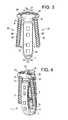
- FIG. 4shows a perspective view of a device of the present invention.
- FIG. 5shows a side view of a device of the present invention.
- FIG. 6shows a perspective view of a device of the present invention without its cage.
- FIG. 7discloses a perspective view of a first embodiment of a polyaxial assembly of the present invention.
- FIG. 8discloses a perspective view of the plate and nub components of the first embodiment of a polyaxial assembly of the present invention.
- FIG. 9shows a side view of the first embodiment of a polyaxial assembly of the present invention.
- FIG. 10shows a top view of the first embodiment of a polyaxial assembly of the present invention.
- FIG. 11discloses a cross-section view of a second embodiment of a polyaxial assembly of the present invention.
- FIG. 12shows a top view of a concave bone plate attached to a sidewall of a vertebral body.
- FIG. 13shows a side view of a concave bone plate attached to both sidewalls of adjacent vertebral bodies.
- FIG. 14discloses a side view of a conventional fusion device comprising an integral cage and plate.
- FIG. 15is a side view of a device of the present invention in which the nub and plate are integral.
- FIG. 16discloses a threaded post of the present invention.
- FIG. 17discloses a post of the present invention having a spherical head.
- FIG. 18discloses a side view of a conventional cage-plate assembly inserted in a disc space.
- an intervertebral fusion devicecomprising:
- the assemblyhas a polyaxial joint. It is believed that the inclusion of this polyaxial joint is very advantageous to the performance of the device. It has been noticed that typical variations in human physiology often result in a situation in which the sidewalls of the adjacent vertebrae that hold the plate are not coplanar with each other. Rather, one sidewall often extends out farther than its adjacent sidewall. Thus, when a conventional cage-plate assembly (in which the plate is rigidly attached to the cage in a perpendicular relationship) is used on a typical functional spinal unit, the lack of a coplanar relationship in the vertebral sidewalls leads to a fixation situation in which only one of the vertebral sidewalls will actually contact the plate. This asymmetrical contact undesirably leads to stress concentration and poor distribution of biomechanical forces (as one screw is loaded more), leading to bony fracture.
- the platecan be polyaxially adjusted about the cage until it contacts each of the sidewalls and then locked at that desired angle. This produces a fixation in which asymmetrical contact is eliminated.
- an intervertebral fusion devicecomprising:
- an assembly device for fusing a disc spacecomprising:
- the proximal head of the postcomprises a spherical surface 43 .
- This spherical surfacecan form a polyaxial joint with a mating spherical surface 45 formed in the central hole of the plate.
- the polyaxial connectionis advantageous for adjusting the orientation of the plate so that it evenly contacts both sidewalls of the adjacent vertebral bodies.
- an interbody device for fusing a disc spacecomprising:
- proximal spherical head of the postis received in the spherical surface of the central hole of the bone plate to form a polyaxial joint
- the second wall of the nub(which contacts the bone plate) has a convex surface 47 .
- This convex surfaceis useful in the polyaxial joint embodiments of the present invention because it accommodates more tilting of the plate with respect to the nub while maintaining the joint.
- the inner surface of the bone platehas a concave surface 49 .
- This concave surfaceis useful in the polyaxial joint embodiments in which the second wall of the nub is convex because it accommodates more tilting of the plate with respect to the nub while maintaining the joint.
- the shaft 95 of the upper bone anchor 91 and the upper surface 13 of the cagedefine a first angle ⁇
- the shaft 96 of the lower bone anchor 92 and the lower surface 15 of the cagedefine a second angle ⁇
- the first angle ⁇is not equal to second angle ⁇ .
- the first angle ⁇differs from second angle ⁇ by at least 5 degrees.
- the platehas an annular projection 51 extending distally from its inner surface 52 about the central hole, and the nub has a recessed surface 53 extending distally about its throughhole 54 from its second wall, so that the annular projection forms a polyaxial joint 55 with the recessed surface of the nub.
- the polyaxial nature of the connection between the plate and nuballows the plate to float over the nub. This ability to float facilitates the plate's fit upon vertebral body sidewall surfaces that are often not aligned in a coplanar manner.
- a postmay be added to the assembly by passing it through the plate's central hole and attaching to the nub's throughhole. Now referring to FIG.
- a thread 57 on the post's shaft 58allows it to threadably mate with the throughhole of the nub, while a head 59 on the proximal end portion 61 of the post allows it to loosely retain the plate upon the nub.
- the postacts to retain the plate on the nub while allowing the polyaxial connection to retain its ability to move.
- the device of FIG. 11represents the first polyaxial plate known to the present inventors.
- an interbody device for fusing a disc spacecomprising:
- annular projection of the bone plateforms a polyaxial joint with the recessed surface of the intervertebral component.
- the cage of the present inventioncan be any interbody fusion cage suitable for promoting fusion between two vertebral bodies.
- the cagecan be adapted for lumbar, cervical or thoracic use.
- the cagecan be adapted for lateral, posterior, or anterior insertion.
- the cageis adapted for lateral approach to the lumbar spine.
- the cagewill have an anterior wall, a posterior wall, leading and trailing walls connecting the anterior and posterior walls to form a central vertical throughhole, an upper surface adapted for gripping an upper endplate and a lower surface adapted for gripping a lower endplate.
- the central vertical throughholefacilitates bone growth between the two adjacent vertebral endplates.
- Each of the posterior and anterior wallsmay have ventral-dorsal throughholes 62 therethrough in order to accommodate fusion as well.
- the leading wall of the lateral cagemay have a bulleted nose 63 that eases insertion into the disc space.
- the bone plate of the present inventiontypically comprises a bone-contacting inner surface, an outer surface, and upper and lower holes passing from the bone-contacting surface to the outer surface. Bone anchors pass through these upper and lower holes to thereby anchor the plate to the adjacent vertebral bodies.
- the central hole of the plate(into which the post seats) opens laterally onto a sidewall 65 of the plate.
- the purpose of this lateral openingis to allow a snap-fit assembly. It is believed that when this opening constitutes about 40% of the central hole periphery, the snap fit will be sufficiently robust so as to hold plate on the post.
- the central hole in the plateis provided in the form of an elongated slot.
- the elongated slotallows for slidable adjustment of the plate upon the nub, thereby allowing for a fine tuning of the plate location after the nub location is set.
- the bone-contacting inner surface of the platenarrows distally. This contouring helps the plate fit between the adjacent vertebrae. This feature is believed to be advantageous in MIS procedures in which the components are inserted into the spinal area through a tube in the absence of a clear line of sight on the part of the surgeon.
- the outer surface 67 of the bone plateis convex. This condition helps the plate conform to the convex bony surfaces of the adjacent vertebrae.
- the bone-contacting inner surface 69 of the bone plateis concave. This condition helps the plate conform to the convex bony surfaces of the adjacent vertebrae.
- the inner surface of the platefurther comprises a radius 201 and a projection 203 .
- This radiusadvantageously matches the contour of the vertebral body in this region.
- the purpose of the nubis to prevent undesired pivoting of the plate about its centerpoint.
- the cage, plate and nubare present as separate components. This condition maximizes the surgeon's ability to adjust the location of the plate after fixing the locations of the cage and nub.
- the nub and plateare an integral component 71 that is separate from the cage 73 .
- an intervertebral fusion devicecomprising:
- the nubfurther comprises:
- grippingis accomplished by providing a plurality of teeth 75 upon each of the upper and lower surfaces.
- the purpose of these nub teethis to enhance the snug fit of the nub between the vertebral bodies and thereby further prevent the rocking of the plate.
- the upper surface and lower surface of the cagedefine a cage height
- the lower surface and upper surface of the nubdefine a nub height
- the nub height H Nis not greater than the cage height H C .
- the nub heightis not less than the cage height. This condition enhances the snug fit of the nub between the vertebral bodies and thereby further prevent the rocking of the plate.
- the nub heightis substantially the same as the cage height. This condition possess the attributes of the two conditions described above.
- the nubnarrows distally. This contouring helps the nub locate the hole in the annulus through which the cage has been placed. This feature is believed to be advantageous in MIS procedures in which the components are inserted into the spinal area through a tube without the surgeon having a clear line of sight.
- the posthas a threaded distal end portion adapted for threadable mating to the central hole of the nub.
- the posthas a proximal end portion forming an enlarged head.
- the proximal head 81has a spherical portion 83 .
- the postpasses through the central hole of the plate and threads into the nub.
- the postcan thread into the cage as well.
- the device of the present inventionalso comprises upper and lower bone anchors 91 , 92 received in the respective upper and lower holes, each bone anchor having a proximal head 93 , 94 and a distal shaft 95 , 96 .
- the bone anchoris a screw that has a threaded shaft 97 , 98 .
- the device of the present inventionalso comprises first and second cams 101 threadably received in the respective threaded recesses 103 of the bone plate and bearing against the respective heads of the bone anchors. These cams tighten against the heads of the screws, thereby preventing screw backout.
- the cages of the present inventionmay be made from any non-resorbable material appropriate for human surgical implantation, including but not limited to, surgically appropriate metals, and non-metallic materials, such as carbon fiber composites, polymers and ceramics.
- the interbody devicesare preferably made out of PEEK or CFRP or any other suitable material providing adequate strength and radiolucency.
- implantable metalssuch as titanium or stainless steel components may be required to ensure adequate strength for either the interbody device.
- the interbody devicecan be made as a combination of PEEK and metal.
- resorbable materialssuch as polylactide, polyglycolide, and magnesium are preferred.
- the cage materialis selected from the group consisting of PEEK, ceramic and metallic.
- the cage materialis preferably selected from the group consisting of metal and composite (such as PEEK/carbon fiber).
- the metalis preferably selected from the group consisting of titanium, titanium alloys (such as Ti-6Al-4V), chrome alloys (such as CrCo or Cr—Co—Mo) and stainless steel.
- the polymeris preferably selected from the group consisting of polyesters, (particularly aromatic esters such as polyalkylene terephthalates, polyamides; polyalkenes; poly(vinyl fluoride); PTFE; polyarylethyl ketone PAEK; polyphenylene and mixtures thereof.
- the ceramicis preferably selected from the group consisting of alumina, zirconia and mixtures thereof. It is preferred to select an alumina-zirconia ceramic, such as BIOLOX DeltaTM, available from CeramTec of Plochingen, Germany.
- the cage membercomprises PEEK. In others, it is a ceramic.
- the first componentconsists essentially of a metallic material, preferably a titanium alloy or a chrome-cobalt alloy.
- the componentsare made of a stainless steel alloy, preferably BioDur® CCM Plus® Alloy available from Carpenter Specialty Alloys, Carpenter Technology Corporation of Wyomissing, Pa.
- the outer surfaces of the componentsare coated with a sintered beadcoating, preferably PorocoatTM, available from DePuy Orthopaedics of Warsaw, Ind.
- the componentsare made from a composite comprising carbon fiber.
- Composites comprising carbon fiberare advantageous in that they typically have a strength and stiffness that is superior to neat polymer materials such as a polyarylethyl ketone PAEK.
- each componentis made from a polymer composite such as a PEKK-carbon fiber composite.
- the composite comprising carbon fiberfurther comprises a polymer.
- the polymeris a polyarylethyl ketone (PAEK). More preferably, the PAEK is selected from the group consisting of polyetherether ketone (PEEK), polyether ketone ketone (PEKK) and polyether ketone (PEK). In preferred embodiments, the PAEK is PEEK.
- the carbon fibercomprises between 1 vol % and 60 vol % (more preferably, between 10 vol % and 50 vol %) of the composite.
- the polymer and carbon fibersare homogeneously mixed.
- the materialis a laminate.
- the carbon fiberis present in a chopped state.
- the chopped carbon fibershave a median length of between 1 mm and 12 mm, more preferably between 4.5 mm and 7.5 mm.
- the carbon fiberis present as continuous strands.
- the compositecomprises:
- the compositeconsists essentially of PAEK and carbon fiber. More preferably, the composite comprises 60-80 wt % PAEK and 20-40 wt % carbon fiber. Still more preferably the composite comprises 65-75 wt % PAEK and 25-35 wt % carbon fiber.
- the post and screw components of the present inventionare made from a biocompatible metal, such as stainless steel, chromium cobalt, or titanium alloy.
- the plates of the present inventionare made from a biocompatible metal, such as stainless steel, chromium cobalt, or titanium alloy.
- the central throughhole of the cageis filled with a fusion material.
- This fusion materialpromotes bony fusion of the adjacent vertebral bodies through the disc space.
- the fusion materialmay be autograft bone marrow or allograft bone.
- the fusion materialmay be synthetic, such as tricalcium phosphate or hydroxyapatite.
- the fusion materialmay be a recombinant protein, such as a growth factor.
- the corresponding implantAfter successfully accessing, clearing and sizing the disc space, select the corresponding implant, fill the cage implant with autogenous bone graft material and attach to the inserter. Gently impact the cage implant into the disc space while monitoring placement under AP fluoroscopy. Ideal placement of the implant is to support the endplate medial/laterally to the contra-lateral rim and between the anterior third and middle third of the disc space from an anterior/posterior perspective.
- nubbed plate implantbased on morphology and cage size, attach it to its respective inserter.
- the cageas a guide, insert the plate until the nubbed portion is within the disc space supporting the vertebral body rim and the plate portion abuts the ipsilateral walls of the superior and inferior vertebral bodies.
- the nubbed platecan be slightly repositioned from the cage location anteriorly or posteriorly in order to optimize the screw location or to account for anomalies such as osteophytes or a slightly compromised cage trajectory.
- the corresponding implantAfter successfully accessing, clearing and sizing the disc space, select the corresponding implant, fill the cage portion with autogenous bone graft material and attach the plate-cage combination to the inserter. Gently impact the implant into the disc space while monitoring placement under AP fluoroscopy. Ideal placement of the implant is for the cage portion to support the endplate medial/laterally to the contra-lateral rim and for the nubbed portion to support the ipsilateral rim while the plate portion is in contact with the walls of the superior and inferior vertebral bodies.
- the implantshould be between the anterior third and middle third of the disc space from an anterior/posterior perspective.
- the nubbed plate portioncan only be slightly repositioned from the cage based on the extent of the polyaxial/sliding connection between the plate and nubbed portion. This allows for a diminished ability to accommodate morphological or surgical anomalies but increases the ergonomics of the surgery by reducing it to a single insertion technique.
- the nubsupports the ipsilateral rim of the vertebral body and the cage supports the contralateral rim of the vertebral body.
Landscapes
- Health & Medical Sciences (AREA)
- Engineering & Computer Science (AREA)
- Biomedical Technology (AREA)
- Orthopedic Medicine & Surgery (AREA)
- Neurology (AREA)
- Life Sciences & Earth Sciences (AREA)
- Animal Behavior & Ethology (AREA)
- Veterinary Medicine (AREA)
- Heart & Thoracic Surgery (AREA)
- Public Health (AREA)
- General Health & Medical Sciences (AREA)
- Cardiology (AREA)
- Oral & Maxillofacial Surgery (AREA)
- Transplantation (AREA)
- Vascular Medicine (AREA)
- Surgery (AREA)
- Molecular Biology (AREA)
- Medical Informatics (AREA)
- Nuclear Medicine, Radiotherapy & Molecular Imaging (AREA)
- Prostheses (AREA)
- Surgical Instruments (AREA)
Abstract
Description
- a) an intervertebral fusion cage having an anterior wall, a posterior wall, leading and trailing walls connecting the anterior and posterior walls to form a central vertical throughhole, an upper surface adapted for gripping an upper endplate and a lower surface adapted for gripping a lower endplate;
- b) a bone plate comprising upper and lower holes,
- c) a separate nub component interposed between the bone plate and the trailing wall of the cage.
- a) an
intervertebral fusion cage 1 having ananterior wall 3, aposterior wall 5, a leadingwall 7 and a trailingwall 9 connecting the anterior and posterior walls to form a centralvertical throughhole 11, anupper surface 13 adapted for gripping an upper endplate and alower surface 15 adapted for gripping a lower endplate; - b) a
bone plate 21 comprising anupper hole 23, alower hole 25, and acentral hole 27 disposed substantially between the first and second holes, - c) a
nub 31 interposed between the bone plate and the trailing wall of the cage, the nub comprising:- i) a
first wall 33 contacting the trailing wall of the cage, - ii) a
second wall 35 contacting the bone plate, - iii) a threaded throughhole37 extending from the first wall to the second wall, and
- i) a
- d) a threaded
post 41 received in the throughhole of the nub and passing through the central hole of the bone plate.
- a) an
- a) an intervertebral fusion cage having an anterior wall, a posterior wall, leading and trailing walls connecting the anterior and posterior walls to form a central vertical throughhole, an upper surface adapted for gripping an upper endplate and a lower surface adapted for gripping a lower endplate, the upper and lower surface defining a cage height;
- b) a bone plate comprising a bone contacting surface, and outer surface, upper and lower holes passing from the bone-contacting surface to the outer surface, and a projection extending distally from the bone contacting surface and having a height,
wherein the bone plate is connected to the trailing wall of the cage via a polyaxial connection.
- a) a bone plate comprising a bone-contacting inner surface, an outer surface, upper and lower holes, a central hole, each hole passing from the outer surface to the inner surface,
- b) an intervertebral component comprising:
- i) a first wall facing the disc space,
- ii) a second wall contacting the inner surface of the bone plate,
- c) first and second bone anchors passing through the upper and lower holes of the bone plate,
wherein the bone plate forms a polyaxial joint with the intervertebral component.
- a) a bone plate comprising a bone contacting inner surface, an outer surface, upper and lower holes, a central hole having a spherical surface thereon, each hole passing from the outer surface to the inner surface,
- b) an intervertebral component comprising:
- i) a first wall facing the disc space,
- ii) a second wall contacting the inner surface of the bone plate,
- iii) a threaded throughhole extending from the first wall to the second wall,
- c) first and second bone anchors passing through the upper and lower holes of the bone plate,
- d) a post having a proximal spherical head and a distal threaded shaft,
wherein the inner surface of the bone plate contacts the second wall of the intervertebral component,
wherein the central hole of the bone plate and the threaded throughhole of the intervertebral component align,
wherein the distal threaded shaft of the post is threadably received in the threaded throughhole of the nub, and
- a) a bone plate comprising a bone contacting inner surface, an outer surface, upper and lower holes, a central hole, each hole passing from the outer surface to the inner surface, and an annular projection extending distally from the inner surface about the central hole,
- b) an intervertebral component comprising:
- i) a first wall facing the disc space,
- ii) a second wall contacting the inner surface of the bone plate,
- iii) a throughhole extending from the first wall to the second wall,
- iv) a recessed surface extending distally about the throughhole,
- c) first and second bone anchors passing through the upper and lower holes of the bone plate,
- a) an intervertebral fusion cage having an anterior wall, a posterior wall, leading and trailing walls connecting the anterior and posterior walls to form a central vertical throughhole, an upper surface adapted for gripping an upper endplate and a lower surface adapted for gripping a lower endplate,
- b) a separate bone plate component comprising a bone contacting surface, and outer surface, upper and lower holes passing from the bone-contacting surface to the outer surface, and a projection extending distally from the bone contacting surface,
- iii) an upper surface adapted for gripping an upper endplate, and
- iv) a lower surface adapted for gripping a lower endplate
wherein each of the upper and lower surfaces of the nub is disposed between the first and second walls of the nub.
- 40-99% (more preferably, 60-80 vol %) polyarylethyl ketone (PAEK), and
- 1-60% (more preferably, 20-40 vol %) carbon fiber,
wherein the polyarylethyl ketone (PAEK) is selected from the group consisting of polyetherether ketone (PEEK), polyether ketone ketone (PEKK) and polyether ketone (PEK).
Claims (17)
Priority Applications (11)
| Application Number | Priority Date | Filing Date | Title |
|---|---|---|---|
| US13/413,264US9271836B2 (en) | 2012-03-06 | 2012-03-06 | Nubbed plate |
| EP13757720.1AEP2822486A4 (en) | 2012-03-06 | 2013-03-05 | Nubbed plate |
| PCT/US2013/029026WO2013134210A1 (en) | 2012-03-06 | 2013-03-05 | Nubbed plate |
| JP2014561019AJP2015512686A (en) | 2012-03-06 | 2013-03-05 | Plate with small bumps |
| AU2013230198AAU2013230198A1 (en) | 2012-03-06 | 2013-03-05 | Nubbed plate |
| US14/845,481US9668877B2 (en) | 2012-03-06 | 2015-09-04 | Nubbed plate |
| US15/214,764US9662225B2 (en) | 2012-03-06 | 2016-07-20 | Nubbed plate |
| US15/581,571US9872781B2 (en) | 2012-03-06 | 2017-04-28 | Nubbed plate |
| US15/846,344US10327915B2 (en) | 2012-03-06 | 2017-12-19 | Nubbed plate |
| US16/414,064US11071634B2 (en) | 2012-03-06 | 2019-05-16 | Nubbed plate |
| US17/359,756US11844702B2 (en) | 2012-03-06 | 2021-06-28 | Nubbed plate |
Applications Claiming Priority (1)
| Application Number | Priority Date | Filing Date | Title |
|---|---|---|---|
| US13/413,264US9271836B2 (en) | 2012-03-06 | 2012-03-06 | Nubbed plate |
Related Child Applications (1)
| Application Number | Title | Priority Date | Filing Date |
|---|---|---|---|
| US14/845,481ContinuationUS9668877B2 (en) | 2012-03-06 | 2015-09-04 | Nubbed plate |
Publications (2)
| Publication Number | Publication Date |
|---|---|
| US20130238095A1 US20130238095A1 (en) | 2013-09-12 |
| US9271836B2true US9271836B2 (en) | 2016-03-01 |
Family
ID=49114785
Family Applications (7)
| Application Number | Title | Priority Date | Filing Date |
|---|---|---|---|
| US13/413,264Active2033-07-16US9271836B2 (en) | 2012-03-06 | 2012-03-06 | Nubbed plate |
| US14/845,481ActiveUS9668877B2 (en) | 2012-03-06 | 2015-09-04 | Nubbed plate |
| US15/214,764ActiveUS9662225B2 (en) | 2012-03-06 | 2016-07-20 | Nubbed plate |
| US15/581,571ActiveUS9872781B2 (en) | 2012-03-06 | 2017-04-28 | Nubbed plate |
| US15/846,344ActiveUS10327915B2 (en) | 2012-03-06 | 2017-12-19 | Nubbed plate |
| US16/414,064Active2032-06-09US11071634B2 (en) | 2012-03-06 | 2019-05-16 | Nubbed plate |
| US17/359,756Active2032-07-20US11844702B2 (en) | 2012-03-06 | 2021-06-28 | Nubbed plate |
Family Applications After (6)
| Application Number | Title | Priority Date | Filing Date |
|---|---|---|---|
| US14/845,481ActiveUS9668877B2 (en) | 2012-03-06 | 2015-09-04 | Nubbed plate |
| US15/214,764ActiveUS9662225B2 (en) | 2012-03-06 | 2016-07-20 | Nubbed plate |
| US15/581,571ActiveUS9872781B2 (en) | 2012-03-06 | 2017-04-28 | Nubbed plate |
| US15/846,344ActiveUS10327915B2 (en) | 2012-03-06 | 2017-12-19 | Nubbed plate |
| US16/414,064Active2032-06-09US11071634B2 (en) | 2012-03-06 | 2019-05-16 | Nubbed plate |
| US17/359,756Active2032-07-20US11844702B2 (en) | 2012-03-06 | 2021-06-28 | Nubbed plate |
Country Status (5)
| Country | Link |
|---|---|
| US (7) | US9271836B2 (en) |
| EP (1) | EP2822486A4 (en) |
| JP (1) | JP2015512686A (en) |
| AU (1) | AU2013230198A1 (en) |
| WO (1) | WO2013134210A1 (en) |
Cited By (21)
| Publication number | Priority date | Publication date | Assignee | Title |
|---|---|---|---|---|
| US20130325071A1 (en)* | 2012-05-30 | 2013-12-05 | Marcin Niemiec | Aligning Vertebral Bodies |
| US9662225B2 (en)* | 2012-03-06 | 2017-05-30 | DePuy Synthes Products, Inc. | Nubbed plate |
| US20180221155A1 (en)* | 2012-08-03 | 2018-08-09 | Globus Medical, Inc. | Intervertebral implant |
| US10159582B2 (en) | 2011-09-16 | 2018-12-25 | DePuy Synthes Products, Inc. | Removable, bone-securing cover plate for intervertebral fusion cage |
| US10206784B2 (en) | 2008-03-26 | 2019-02-19 | DePuy Synthes Products, Inc. | Posterior intervertebral disc inserter and expansion techniques |
| US10369015B2 (en) | 2010-09-23 | 2019-08-06 | DePuy Synthes Products, Inc. | Implant inserter having a laterally-extending dovetail engagement feature |
| US10500062B2 (en) | 2009-12-10 | 2019-12-10 | DePuy Synthes Products, Inc. | Bellows-like expandable interbody fusion cage |
| US10543101B1 (en)* | 2015-12-01 | 2020-01-28 | Ctl Medical Corporation | Intervertebral implants and related systems and methods |
| US10617530B2 (en) | 2011-07-14 | 2020-04-14 | Seaspine, Inc. | Laterally deflectable implant |
| US10624758B2 (en) | 2009-03-30 | 2020-04-21 | DePuy Synthes Products, Inc. | Zero profile spinal fusion cage |
| US10940016B2 (en) | 2017-07-05 | 2021-03-09 | Medos International Sarl | Expandable intervertebral fusion cage |
| US11020237B2 (en) | 2006-12-22 | 2021-06-01 | Medos International Sarl | Composite vertebral spacers and instrument |
| US11058552B2 (en)* | 2017-06-21 | 2021-07-13 | NVision Biomedical Technologies, LLC | Anterior lumbar interbody fusion cage and plate |
| US11253368B2 (en) | 2017-02-14 | 2022-02-22 | Nanohive Medical Llc | Methods of designing high x-ray lucency lattice structures |
| US11291558B2 (en)* | 2018-07-26 | 2022-04-05 | Nanohive Medical Llc | Dynamic implant fixation plate |
| US11497617B2 (en) | 2019-01-16 | 2022-11-15 | Nanohive Medical Llc | Variable depth implants |
| US11497616B2 (en) | 2012-11-09 | 2022-11-15 | DePuy Synthes Products, Inc. | Interbody device with opening to allow packing graft and other biologics |
| US11529241B2 (en) | 2010-09-23 | 2022-12-20 | DePuy Synthes Products, Inc. | Fusion cage with in-line single piece fixation |
| US11648124B2 (en) | 2017-04-01 | 2023-05-16 | Nanohive Medical Llc | Methods of designing three-dimensional lattice structures for implants |
| US11678996B2 (en) | 2010-09-23 | 2023-06-20 | DePuy Synthes Products, Inc. | Stand alone intervertebral fusion device |
| US11931266B2 (en) | 2016-06-07 | 2024-03-19 | Nanohive Medical Llc | Implant with independent endplates |
Families Citing this family (47)
| Publication number | Priority date | Publication date | Assignee | Title |
|---|---|---|---|---|
| WO2008070863A2 (en) | 2006-12-07 | 2008-06-12 | Interventional Spine, Inc. | Intervertebral implant |
| US20080161929A1 (en) | 2006-12-29 | 2008-07-03 | Mccormack Bruce | Cervical distraction device |
| WO2009089367A2 (en) | 2008-01-09 | 2009-07-16 | Providence Medical Technology, Inc. | Methods and apparatus for accessing and treating the facet joint |
| US8267966B2 (en) | 2008-06-06 | 2012-09-18 | Providence Medical Technology, Inc. | Facet joint implants and delivery tools |
| CA2725811A1 (en) | 2008-06-06 | 2009-12-10 | Providence Medical Technology, Inc. | Facet joint implants and delivery tools |
| US11224521B2 (en) | 2008-06-06 | 2022-01-18 | Providence Medical Technology, Inc. | Cervical distraction/implant delivery device |
| US8287597B1 (en)* | 2009-04-16 | 2012-10-16 | Nuvasive, Inc. | Method and apparatus for performing spine surgery |
| US8491658B1 (en)* | 2009-07-12 | 2013-07-23 | Mohammad Etminan | Interbody fusion implant and related methods |
| US8425569B2 (en)* | 2010-05-19 | 2013-04-23 | Transcorp, Inc. | Implantable vertebral frame systems and related methods for spinal repair |
| US8845728B1 (en)* | 2011-09-23 | 2014-09-30 | Samy Abdou | Spinal fixation devices and methods of use |
| US9370435B2 (en)* | 2011-11-17 | 2016-06-21 | Zimmer Biomet Spine, Inc. | Modular anchor bone fusion cage |
| ES2628444T3 (en) | 2012-02-17 | 2017-08-02 | Medacta International S.A. | Intervertebral implant with improved clamping system for the fixation plate |
| US9693876B1 (en)* | 2012-03-30 | 2017-07-04 | Ali H. MESIWALA | Spinal fusion implant and related methods |
| US10076364B2 (en)* | 2012-06-29 | 2018-09-18 | K2M, Inc. | Minimal-profile anterior cervical plate and cage apparatus and method of using same |
| AU2013282268A1 (en) | 2012-06-29 | 2015-01-22 | DePuy Synthes Products, LLC | Lateral insertion spinal implant |
| US10201433B2 (en) | 2012-10-19 | 2019-02-12 | Tyber Medical Llc | System and method for correcting scoliosis |
| US10864081B2 (en) | 2012-10-19 | 2020-12-15 | Tyber Medical, LLC | Wedge osteotomy device and method of use |
| US9387087B2 (en) | 2012-10-19 | 2016-07-12 | Tyber Medical Llc | Orthopedic systems for spine and tracking control |
| JP6373878B2 (en)* | 2013-02-14 | 2018-08-15 | メダクタ・インターナショナル・ソシエテ・アノニム | Intervertebral implant with improved fixation plate shape |
| US9717601B2 (en) | 2013-02-28 | 2017-08-01 | DePuy Synthes Products, Inc. | Expandable intervertebral implant, system, kit and method |
| US9180022B2 (en)* | 2013-06-28 | 2015-11-10 | DePuy Synthes Products, Inc. | Spinal alignment clip |
| US9283091B2 (en)* | 2013-10-07 | 2016-03-15 | Warsaw Orthopedic, Inc. | Spinal implant system and method |
| US10143499B2 (en)* | 2013-10-09 | 2018-12-04 | Stryker European Holdings I, Llc | Pivoting vertebral plate |
| US9603718B2 (en)* | 2014-02-27 | 2017-03-28 | Alphatec Spine, Inc. | Spacer with temporary fixation plate |
| US9642723B2 (en) | 2014-02-27 | 2017-05-09 | Alphatec Spine, Inc. | Spinal implants and insertion instruments |
| AU2015267055B2 (en)* | 2014-05-27 | 2020-04-02 | Christopher U. Phan | Lateral mass fixation implant |
| USD779065S1 (en) | 2014-10-08 | 2017-02-14 | Nuvasive, Inc. | Anterior cervical bone plate |
| CN104546095B (en)* | 2015-01-27 | 2017-05-24 | 赵建华 | Adaptive floating combined cervical interbody fusion cage |
| US11426290B2 (en) | 2015-03-06 | 2022-08-30 | DePuy Synthes Products, Inc. | Expandable intervertebral implant, system, kit and method |
| US9901461B2 (en)* | 2015-04-21 | 2018-02-27 | Warsaw Orthopedic, Inc. | Spinal implant system and method of use |
| US9987145B2 (en)* | 2015-10-01 | 2018-06-05 | Seth Kevin WILLIAMS | Lateral block plate |
| US11123192B2 (en)* | 2015-10-13 | 2021-09-21 | Cg Bio Co., Ltd. | Cervical spine fixation apparatus |
| EP3474784A2 (en) | 2016-06-28 | 2019-05-01 | Eit Emerging Implant Technologies GmbH | Expandable and angularly adjustable intervertebral cages with articulating joint |
| US11510788B2 (en) | 2016-06-28 | 2022-11-29 | Eit Emerging Implant Technologies Gmbh | Expandable, angularly adjustable intervertebral cages |
| US11491025B2 (en) | 2016-10-25 | 2022-11-08 | Elevation Spine, Inc. | Intervertebral implant and method of use |
| US10398563B2 (en) | 2017-05-08 | 2019-09-03 | Medos International Sarl | Expandable cage |
| US11871968B2 (en) | 2017-05-19 | 2024-01-16 | Providence Medical Technology, Inc. | Spinal fixation access and delivery system |
| US10624760B2 (en)* | 2017-05-22 | 2020-04-21 | Warsaw Orthopedic, Inc. | Spinal implant system and method |
| US10758370B2 (en) | 2017-06-30 | 2020-09-01 | Elevation Spine, Inc. | Interbody spacer and bone plate assembly |
| US11648128B2 (en) | 2018-01-04 | 2023-05-16 | Providence Medical Technology, Inc. | Facet screw and delivery device |
| WO2020061464A1 (en) | 2018-09-21 | 2020-03-26 | Providence Medical Technology, Inc. | Vertebral joint access and decortication devices and methods of using |
| USD945621S1 (en) | 2020-02-27 | 2022-03-08 | Providence Medical Technology, Inc. | Spinal cage |
| CN111437079A (en)* | 2020-05-06 | 2020-07-24 | 上海交通大学医学院附属第九人民医院 | Transverse opening type lumbar interbody fusion cage |
| US11406511B2 (en) | 2020-08-24 | 2022-08-09 | Seth K. WILLIAMS | Lateral spine plate with lateral spine cage anchoring system |
| RU2753142C1 (en)* | 2020-10-16 | 2021-08-12 | федеральное государственное бюджетное образовательное учреждение высшего образования "Северо-Западный государственный медицинский университет им. И.И. Мечникова" Министерства здравоохранения Российской Федерации | Hybrid multi-vector endofixator for stabilising cervical dislocations and platform for installation thereof |
| AU2023270750A1 (en)* | 2022-05-19 | 2025-01-09 | Medos International Sarl | Securement plate for intervertebral implant |
| CN116650180B (en)* | 2023-08-01 | 2023-11-10 | 四川大学华西医院 | Magnetized intervertebral fusion device and implantation method |
Citations (31)
| Publication number | Priority date | Publication date | Assignee | Title |
|---|---|---|---|---|
| US5755796A (en)* | 1996-06-06 | 1998-05-26 | Ibo; Ivo | Prosthesis of the cervical intervertebralis disk |
| US6156037A (en)* | 1998-10-28 | 2000-12-05 | Sdgi Holdings, Inc. | Anterior lateral spine cage-plate fixation device and technique |
| US6432106B1 (en) | 1999-11-24 | 2002-08-13 | Depuy Acromed, Inc. | Anterior lumbar interbody fusion cage with locking plate |
| US20020156475A1 (en) | 1999-10-30 | 2002-10-24 | Aesculap Ag & Co. Kg | Surgical connecting element for fixing adjacently arranged bone plates |
| US6508818B2 (en)* | 1998-08-21 | 2003-01-21 | Synthes (U.S.A.) | Bone anchoring assembly with a snap-in ballhead |
| US20040193269A1 (en) | 2003-03-31 | 2004-09-30 | Depuy Acromed, Inc. | Anterior lumbar interbody fusion cage with locking plate |
| US20070049941A1 (en) | 2005-08-25 | 2007-03-01 | Lanx, Llc | Plate with stabilization |
| US20070055252A1 (en) | 2005-03-17 | 2007-03-08 | Jason Blain | Flanged interbody fusion device with oblong fastener apertures |
| US20070213820A1 (en) | 2003-04-23 | 2007-09-13 | Sepitec Foundation | Spondylodesis Device |
| US20070270965A1 (en) | 2006-04-28 | 2007-11-22 | Joe Ferguson | Orthopedic support locating or centering feature and method |
| US20080051890A1 (en) | 2006-08-11 | 2008-02-28 | Warsaw Orthopedic, Inc. | Intervertebral Implants with Attachable Flanges and Methods of Use |
| US20080183294A1 (en)* | 2005-04-19 | 2008-07-31 | Ali Adl | Hinged Artificial Spinal Disk Drive |
| US7594931B2 (en) | 2001-07-13 | 2009-09-29 | Ldr Medical | Vertebral cage device with modular fixation |
| US20090326580A1 (en)* | 2008-06-25 | 2009-12-31 | Anderson Mark E | Spinal fixation device |
| US20100004747A1 (en) | 2008-07-07 | 2010-01-07 | Jin-Fu Lin | Trans-Vertebral and Intra-Vertebral Plate and Fusion Cage Device for Spinal Interbody Fusion and Method of Operation |
| US20100249935A1 (en) | 2009-03-30 | 2010-09-30 | Slivka Michael A | Zero Profile Spinal Fusion Cage |
| US20100312345A1 (en) | 2009-06-04 | 2010-12-09 | Duffield William E | Intervertebral fusion implant |
| US7887595B1 (en) | 2005-12-05 | 2011-02-15 | Nuvasive, Inc. | Methods and apparatus for spinal fusion |
| WO2011080535A1 (en) | 2009-12-31 | 2011-07-07 | Lrd Medical | Anchoring device, intervertebral implant and implantation instrument |
| US20110184415A1 (en) | 2010-01-26 | 2011-07-28 | Westmark Medical, Llc | Bone screw retention mechanism |
| US20110190892A1 (en)* | 2010-02-01 | 2011-08-04 | X-Spine Systems, Inc. | Spinal implant co-insertion system and method |
| US20110202136A1 (en)* | 2006-10-04 | 2011-08-18 | Seaspine, Inc. | Articulating spinal implant |
| US20120041559A1 (en)* | 2010-08-11 | 2012-02-16 | Warsaw Orthopedic, Inc | Interbody spinal implants with extravertebral support plates |
| US20120150303A1 (en)* | 2007-11-19 | 2012-06-14 | Linares Medical Devices, Llc | Spine support implant including inter vertebral insertable fluid ballastable insert and inter-vertebral web retaining harnesses |
| US8216312B2 (en)* | 2007-05-31 | 2012-07-10 | Zimmer Spine, Inc. | Spinal interbody system and method |
| US8454694B2 (en)* | 2011-03-03 | 2013-06-04 | Warsaw Orthopedic, Inc. | Interbody device and plate for spinal stabilization and instruments for positioning same |
| US20130166027A1 (en)* | 2011-12-22 | 2013-06-27 | Jonathan Bellas | Lateral Cage with Integrated Plate |
| US20130238095A1 (en)* | 2012-03-06 | 2013-09-12 | Nicholas Pavento | Nubbed Plate |
| US8562651B2 (en) | 2011-03-30 | 2013-10-22 | Warsaw Orthopedic, Inc. | Sacroiliac terminal anchor device and method |
| US20130345813A1 (en)* | 2012-06-22 | 2013-12-26 | Sheryl Frank | Dual Anchor Lateral Vertebral Body Fixation Plates |
| US20140172103A1 (en)* | 2012-12-17 | 2014-06-19 | Michael J. O'Neil | Polyaxial Intervertebral Cage |
Family Cites Families (541)
| Publication number | Priority date | Publication date | Assignee | Title |
|---|---|---|---|---|
| US1677337A (en) | 1924-09-27 | 1928-07-17 | Thomas E Grove | Antrum drill |
| US1636636A (en) | 1927-01-20 | 1927-07-19 | William S Humble | Surgical instrument |
| GB457673A (en) | 1934-08-13 | 1936-12-03 | Dominique Paolini | Improvements in or relating to non-refillable bottles |
| US2304703A (en) | 1939-09-27 | 1942-12-08 | Winslow Foster | Screw driver |
| US4208511A (en) | 1977-01-19 | 1980-06-17 | Ethicon, Inc. | Isomorphic copolyoxalates and sutures thereof |
| US4141087A (en) | 1977-01-19 | 1979-02-27 | Ethicon, Inc. | Isomorphic copolyoxalates and sutures thereof |
| US4105034A (en) | 1977-06-10 | 1978-08-08 | Ethicon, Inc. | Poly(alkylene oxalate) absorbable coating for sutures |
| US4205399A (en) | 1977-06-13 | 1980-06-03 | Ethicon, Inc. | Synthetic absorbable surgical devices of poly(alkylene oxalates) |
| US4140678A (en) | 1977-06-13 | 1979-02-20 | Ethicon, Inc. | Synthetic absorbable surgical devices of poly(alkylene oxalates) |
| US4130639A (en) | 1977-09-28 | 1978-12-19 | Ethicon, Inc. | Absorbable pharmaceutical compositions based on isomorphic copolyoxalates |
| US4646741A (en) | 1984-11-09 | 1987-03-03 | Ethicon, Inc. | Surgical fastener made from polymeric blends |
| US4889119A (en) | 1985-07-17 | 1989-12-26 | Ethicon, Inc. | Surgical fastener made from glycolide-rich polymer blends |
| US4743256A (en) | 1985-10-04 | 1988-05-10 | Brantigan John W | Surgical prosthetic implant facilitating vertebral interbody fusion and method |
| CH672588A5 (en) | 1987-07-09 | 1989-12-15 | Sulzer Ag | |
| GB8718627D0 (en) | 1987-08-06 | 1987-09-09 | Showell A W Sugicraft Ltd | Spinal implants |
| US5529580A (en) | 1987-10-30 | 1996-06-25 | Olympus Optical Co., Ltd. | Surgical resecting tool |
| JPH01136655A (en) | 1987-11-24 | 1989-05-29 | Asahi Optical Co Ltd | Movable type pyramid spacer |
| US5609635A (en) | 1988-06-28 | 1997-03-11 | Michelson; Gary K. | Lordotic interbody spinal fusion implants |
| FR2634260A1 (en) | 1988-07-15 | 1990-01-19 | Bristol Myers Co | ELBOW DRIVE DEVICE |
| DE3923995A1 (en) | 1989-07-20 | 1991-01-31 | Lutz Biedermann | BONE STABILIZING ELEMENT |
| DE8912648U1 (en) | 1989-10-23 | 1990-11-22 | Mecron Medizinische Produkte Gmbh, 1000 Berlin | Vertebral body implant |
| JPH066810Y2 (en) | 1989-11-29 | 1994-02-23 | 旭光学工業株式会社 | Vertebral body fixation plate |
| US5464407A (en) | 1991-02-19 | 1995-11-07 | Mcguire; David A. | Flexible surgical screwdriver and methods of arthroscopic ligament reconstruction |
| US5391170A (en) | 1991-12-13 | 1995-02-21 | David A. McGuire | Angled surgical screw driver and methods of arthroscopic ligament reconstruction |
| US5123926A (en) | 1991-02-22 | 1992-06-23 | Madhavan Pisharodi | Artificial spinal prosthesis |
| US5797918A (en) | 1991-12-13 | 1998-08-25 | David A. McGuire | Flexible surgical screwdriver and methods of arthroscopic ligament reconstruction |
| US5534031A (en) | 1992-01-28 | 1996-07-09 | Asahi Kogaku Kogyo Kabushiki Kaisha | Prosthesis for spanning a space formed upon removal of an intervertebral disk |
| US5209751A (en) | 1992-02-19 | 1993-05-11 | Danek Medical, Inc. | Spinal fixation system |
| FR2693899B1 (en) | 1992-07-24 | 1994-09-23 | Laboureau Jacques | Osteosynthesis plate clip. |
| FR2700464B1 (en) | 1992-11-13 | 1995-04-14 | Maurice Bertholet | Connecting piece for bone elements. |
| US5352231A (en) | 1992-11-23 | 1994-10-04 | Danek Medical, Inc. | Nut starter wrench for orthopedic fixation system |
| US6066175A (en)* | 1993-02-16 | 2000-05-23 | Henderson; Fraser C. | Fusion stabilization chamber |
| FR2704135B1 (en) | 1993-04-19 | 1995-07-07 | Savornin Claude | OSTEOSYNTHESIS STAPLE. |
| US5395372A (en) | 1993-09-07 | 1995-03-07 | Danek Medical, Inc. | Spinal strut graft holding staple |
| US5443514A (en) | 1993-10-01 | 1995-08-22 | Acromed Corporation | Method for using spinal implants |
| CN1156255C (en) | 1993-10-01 | 2004-07-07 | 美商-艾克罗米德公司 | Spinal implant |
| US5397364A (en) | 1993-10-12 | 1995-03-14 | Danek Medical, Inc. | Anterior interbody fusion device |
| US5499986A (en) | 1994-01-07 | 1996-03-19 | Smith & Nephew Richards Inc. | Quick release handle apparatus for removing and inserting intramedullary nails |
| US5443515A (en) | 1994-01-26 | 1995-08-22 | Implex Corporation | Vertebral body prosthetic implant with slidably positionable stabilizing member |
| US5620458A (en) | 1994-03-16 | 1997-04-15 | United States Surgical Corporation | Surgical instruments useful for endoscopic spinal procedures |
| CA2551185C (en) | 1994-03-28 | 2007-10-30 | Sdgi Holdings, Inc. | Apparatus and method for anterior spinal stabilization |
| JP3509103B2 (en) | 1994-05-23 | 2004-03-22 | スルザー スパイン−テック インコーポレイテッド | Intervertebral fusion implant |
| AU3207895A (en) | 1994-08-23 | 1996-03-14 | Spine-Tech, Inc. | Cervical spine stabilization system |
| US5601553A (en) | 1994-10-03 | 1997-02-11 | Synthes (U.S.A.) | Locking plate and bone screw |
| US5607687A (en) | 1995-03-06 | 1997-03-04 | Ethicon, Inc. | Polymer blends containing absorbable polyoxaesters |
| US5859150A (en) | 1995-03-06 | 1999-01-12 | Ethicon, Inc. | Prepolymers of absorbable polyoxaesters |
| US5698213A (en) | 1995-03-06 | 1997-12-16 | Ethicon, Inc. | Hydrogels of absorbable polyoxaesters |
| US5648088A (en) | 1995-03-06 | 1997-07-15 | Ethicon, Inc. | Blends of absorbable polyoxaesters containing amines and/or amide groups |
| US5618552A (en) | 1995-03-06 | 1997-04-08 | Ethicon, Inc. | Absorbable polyoxaesters |
| US5700583A (en) | 1995-03-06 | 1997-12-23 | Ethicon, Inc. | Hydrogels of absorbable polyoxaesters containing amines or amido groups |
| US5597579A (en) | 1995-03-06 | 1997-01-28 | Ethicon, Inc. | Blends of absorbable polyoxaamides |
| US5595751A (en) | 1995-03-06 | 1997-01-21 | Ethicon, Inc. | Absorbable polyoxaesters containing amines and/or amido groups |
| US5464929A (en) | 1995-03-06 | 1995-11-07 | Ethicon, Inc. | Absorbable polyoxaesters |
| US5591166A (en)* | 1995-03-27 | 1997-01-07 | Smith & Nephew Richards, Inc. | Multi angle bone bolt |
| US6206922B1 (en) | 1995-03-27 | 2001-03-27 | Sdgi Holdings, Inc. | Methods and instruments for interbody fusion |
| US5634926A (en) | 1995-04-25 | 1997-06-03 | Jobe; Richard P. | Surgical bone fixation apparatus |
| FR2733413B1 (en) | 1995-04-27 | 1997-10-17 | Jbs Sa | CERVICAL CAGE DEVICE FOR PERFORMING INTERSOMATIC ARTHRODESIS |
| US5578034A (en) | 1995-06-07 | 1996-11-26 | Danek Medical, Inc. | Apparatus for preventing screw backout in a bone plate fixation system |
| CA2158890C (en) | 1995-09-22 | 2002-01-22 | John Runciman | Spherical washer for use with a bone screw |
| US5989289A (en) | 1995-10-16 | 1999-11-23 | Sdgi Holdings, Inc. | Bone grafts |
| US6423095B1 (en) | 1995-10-16 | 2002-07-23 | Sdgi Holdings, Inc. | Intervertebral spacers |
| CA2242645A1 (en) | 1995-12-08 | 1997-06-12 | Robert S. Bray, Jr. | Anterior stabilization device |
| US5766253A (en) | 1996-01-16 | 1998-06-16 | Surgical Dynamics, Inc. | Spinal fusion device |
| FR2747034B1 (en) | 1996-04-03 | 1998-06-19 | Scient X | INTERSOMATIC CONTAINMENT AND MERGER SYSTEM |
| US5824084A (en) | 1996-07-03 | 1998-10-20 | The Cleveland Clinic Foundation | Method of preparing a composite bone graft |
| DE19630256A1 (en) | 1996-07-26 | 1998-01-29 | Heinrich Ulrich | Implant for fusing two adjacent vertebrae of the spine |
| US5800435A (en)* | 1996-10-09 | 1998-09-01 | Techsys, Llc | Modular spinal plate for use with modular polyaxial locking pedicle screws |
| FR2754702B1 (en) | 1996-10-18 | 1999-01-08 | Medinov Amp | DEVICE FOR SOLIDARIZING AT LEAST TWO VERTEBRAL BODIES |
| US5904689A (en) | 1996-10-18 | 1999-05-18 | Jonjic; Leo | Surgical angled screwdriver |
| US20050165483A1 (en) | 2004-01-27 | 2005-07-28 | Ray Eddie F.Iii | Bone grafts |
| US6190414B1 (en) | 1996-10-31 | 2001-02-20 | Surgical Dynamics Inc. | Apparatus for fusion of adjacent bone structures |
| US6139550A (en) | 1997-02-11 | 2000-10-31 | Michelson; Gary K. | Skeletal plating system |
| ES2297092T3 (en) | 1997-02-11 | 2008-05-01 | Warsaw Orthopedic, Inc. | PREVIOUS CERVICAL PLATE OF UNIQUE BLOCK. |
| US6039761A (en) | 1997-02-12 | 2000-03-21 | Li Medical Technologies, Inc. | Intervertebral spacer and tool and method for emplacement thereof |
| EP1905392B1 (en) | 1997-03-07 | 2011-05-18 | Kyphon SÀRL | System for percutaneous bone and spinal stabilization, fixation and repair |
| IL128261A0 (en) | 1999-01-27 | 1999-11-30 | Disc O Tech Medical Tech Ltd | Expandable element |
| US20070282443A1 (en) | 1997-03-07 | 2007-12-06 | Disc-O-Tech Medical Technologies Ltd. | Expandable element |
| DE19710392C1 (en) | 1997-03-13 | 1999-07-01 | Haehnel Michael | Slipped disc implant comprises an extensible, hinged or wound body |
| US5800440A (en) | 1997-03-18 | 1998-09-01 | Johnson & Johnson Professional, Inc. | Device for inserting a surgical pin |
| AU744371B2 (en) | 1997-04-25 | 2002-02-21 | Stryker European Holdings I, Llc | Two-part intersomatic implant |
| US6306170B2 (en) | 1997-04-25 | 2001-10-23 | Tegementa, L.L.C. | Threaded fusion cage anchoring device and method |
| US5893889A (en) | 1997-06-20 | 1999-04-13 | Harrington; Michael | Artificial disc |
| GB9713330D0 (en) | 1997-06-25 | 1997-08-27 | Bridport Gundry Plc | Surgical implant |
| US6454769B2 (en) | 1997-08-04 | 2002-09-24 | Spinal Concepts, Inc. | System and method for stabilizing the human spine with a bone plate |
| FR2767675B1 (en) | 1997-08-26 | 1999-12-03 | Materiel Orthopedique En Abreg | INTERSOMATIC IMPLANT AND ANCILLARY OF PREPARATION SUITABLE FOR ALLOWING ITS POSITION |
| ES2226186T3 (en) | 1997-11-29 | 2005-03-16 | Surgicraft Limited | SURGICAL IMPLANT AND SURGICAL FIXING SCREW. |
| US5913860A (en) | 1998-02-27 | 1999-06-22 | Synthes (Usa) | Surgical nail inserter |
| US6224631B1 (en) | 1998-03-20 | 2001-05-01 | Sulzer Spine-Tech Inc. | Intervertebral implant with reduced contact area and method |
| US6835208B2 (en) | 1998-03-30 | 2004-12-28 | J. Alexander Marchosky | Prosthetic system |
| WO1999049818A1 (en) | 1998-03-30 | 1999-10-07 | Marchosky J Alexander | Prosthetic system |
| US6008433A (en) | 1998-04-23 | 1999-12-28 | Stone; Kevin R. | Osteotomy wedge device, kit and methods for realignment of a varus angulated knee |
| US6679915B1 (en) | 1998-04-23 | 2004-01-20 | Sdgi Holdings, Inc. | Articulating spinal implant |
| US6126689A (en) | 1998-06-15 | 2000-10-03 | Expanding Concepts, L.L.C. | Collapsible and expandable interbody fusion device |
| DE19826619A1 (en) | 1998-06-17 | 1999-12-30 | Ulrich Gmbh & Co Kg | Implant for the fusion of two vertebrae |
| US6086593A (en) | 1998-06-30 | 2000-07-11 | Bonutti; Peter M. | Method and apparatus for use in operating on a bone |
| DE29813139U1 (en) | 1998-07-23 | 1998-12-03 | Howmedica GmbH, 24232 Schönkirchen | Vertebral body reconstruction system |
| US6099531A (en) | 1998-08-20 | 2000-08-08 | Bonutti; Peter M. | Changing relationship between bones |
| US6117174A (en) | 1998-09-16 | 2000-09-12 | Nolan; Wesley A. | Spinal implant device |
| US6159211A (en) | 1998-10-22 | 2000-12-12 | Depuy Acromed, Inc. | Stackable cage system for corpectomy/vertebrectomy |
| US6174311B1 (en) | 1998-10-28 | 2001-01-16 | Sdgi Holdings, Inc. | Interbody fusion grafts and instrumentation |
| US6193757B1 (en) | 1998-10-29 | 2001-02-27 | Sdgi Holdings, Inc. | Expandable intervertebral spacers |
| US6159244A (en) | 1999-07-30 | 2000-12-12 | Suddaby; Loubert | Expandable variable angle intervertebral fusion implant |
| US6547823B2 (en) | 1999-01-22 | 2003-04-15 | Osteotech, Inc. | Intervertebral implant |
| US6056749A (en) | 1999-03-15 | 2000-05-02 | Spineology, Inc. | Method and device for fixing and correcting spondylolisthesis anteriorly |
| AU4246000A (en) | 1999-04-16 | 2000-11-02 | Nuvasive, Inc. | Articulation systems for positioning minimally invasive surgical tools |
| US6325805B1 (en) | 1999-04-23 | 2001-12-04 | Sdgi Holdings, Inc. | Shape memory alloy staple |
| US6342055B1 (en) | 1999-04-29 | 2002-01-29 | Theken Surgical Llc | Bone fixation system |
| US6342074B1 (en) | 1999-04-30 | 2002-01-29 | Nathan S. Simpson | Anterior lumbar interbody fusion implant and method for fusing adjacent vertebrae |
| AU4988700A (en) | 1999-05-05 | 2000-11-17 | Gary K. Michelson | Spinal fusion implants with opposed locking screws |
| EP1198208B1 (en) | 1999-05-05 | 2013-07-10 | Warsaw Orthopedic, Inc. | Nested interbody spinal fusion implants |
| US7094239B1 (en) | 1999-05-05 | 2006-08-22 | Sdgi Holdings, Inc. | Screws of cortical bone and method of manufacture thereof |
| US6579321B1 (en) | 1999-05-17 | 2003-06-17 | Vanderbilt University | Intervertebral disc replacement prosthesis |
| US6200306B1 (en) | 1999-05-26 | 2001-03-13 | Sulzer Carbomedics Inc. | Bend clip for flexible rotator |
| US6770096B2 (en) | 1999-07-01 | 2004-08-03 | Spinevision S.A. | Interbody spinal stabilization cage and spinal stabilization method |
| AU5701200A (en) | 1999-07-02 | 2001-01-22 | Petrus Besselink | Reinforced expandable cage |
| WO2001008864A1 (en) | 1999-07-29 | 2001-02-08 | Materials Innovation, Inc. | Hydraulic powder press |
| US6231610B1 (en) | 1999-08-25 | 2001-05-15 | Allegiance Corporation | Anterior cervical column support device |
| DE60030989T2 (en) | 1999-08-26 | 2007-05-24 | Warsaw Orthopedic, Inc., Warsaw | DEVICE FOR IMPLANTING FUSION CAGE |
| AU7118100A (en) | 1999-09-03 | 2001-04-10 | Daniel J. Cook | Temporary spine fixation device and method |
| US7060100B2 (en) | 1999-10-08 | 2006-06-13 | Ferree Bret A | Artificial disc and joint replacements with modular cushioning components |
| US20040260286A1 (en) | 1999-10-08 | 2004-12-23 | Ferree Bret A. | Intradiscal devices with anti-extrusion keels |
| US6224602B1 (en) | 1999-10-11 | 2001-05-01 | Interpore Cross International | Bone stabilization plate with a secured-locking mechanism for cervical fixation |
| US6830570B1 (en) | 1999-10-21 | 2004-12-14 | Sdgi Holdings, Inc. | Devices and techniques for a posterior lateral disc space approach |
| US6461359B1 (en) | 1999-11-10 | 2002-10-08 | Clifford Tribus | Spine stabilization device |
| US6592624B1 (en) | 1999-11-24 | 2003-07-15 | Depuy Acromed, Inc. | Prosthetic implant element |
| KR200188511Y1 (en) | 2000-01-06 | 2000-07-15 | 구자교 | A supplement plug for spinal colulm |
| TW431172U (en) | 2000-02-02 | 2001-04-21 | Lin Jr Yi | Device with side plate for fastening and restoring spine |
| US6814756B1 (en) | 2000-02-04 | 2004-11-09 | Gary K. Michelson | Expandable threaded arcuate interbody spinal fusion implant with lordotic configuration during insertion |
| DE10005137C2 (en) | 2000-02-04 | 2002-11-07 | Degussa | Screwdriver for intraoral implantation |
| US6500205B1 (en) | 2000-04-19 | 2002-12-31 | Gary K. Michelson | Expandable threaded arcuate interbody spinal fusion implant with cylindrical configuration during insertion |
| US7601171B2 (en)* | 2003-10-23 | 2009-10-13 | Trans1 Inc. | Spinal motion preservation assemblies |
| EP1263353A2 (en) | 2000-03-10 | 2002-12-11 | SDGI Holdings, Inc. | Synthetic reinforced interbody fusion implants |
| US6821298B1 (en) | 2000-04-18 | 2004-11-23 | Roger P. Jackson | Anterior expandable spinal fusion cage system |
| US6330845B1 (en) | 2000-05-17 | 2001-12-18 | Bristol-Myers Squibb | Wrench for an implant |
| US7516154B2 (en) | 2000-06-28 | 2009-04-07 | Qnaturally Systems Inc. | Cross language advertising |
| US7018416B2 (en) | 2000-07-06 | 2006-03-28 | Zimmer Spine, Inc. | Bone implants and methods |
| US6808537B2 (en) | 2000-07-07 | 2004-10-26 | Gary Karlin Michelson | Expandable implant with interlocking walls |
| US6730127B2 (en) | 2000-07-10 | 2004-05-04 | Gary K. Michelson | Flanged interbody spinal fusion implants |
| US6852126B2 (en) | 2000-07-17 | 2005-02-08 | Nuvasive, Inc. | Stackable interlocking intervertebral support system |
| US6447546B1 (en) | 2000-08-11 | 2002-09-10 | Dale G. Bramlet | Apparatus and method for fusing opposing spinal vertebrae |
| US7114501B2 (en) | 2000-08-14 | 2006-10-03 | Spine Wave, Inc. | Transverse cavity device and method |
| US6629998B1 (en) | 2000-08-23 | 2003-10-07 | Chih-I Lin | Intervertebral retrieval device |
| DE60139262D1 (en) | 2000-08-28 | 2009-08-27 | Disc Dynamics Inc | SYSTEM FOR RECONSTRUCTING JOINT SURFACES OF MAMMALS |
| US20020029082A1 (en) | 2000-08-29 | 2002-03-07 | Muhanna Nabil L. | Vertebral spacer and method of use |
| US6824565B2 (en) | 2000-09-08 | 2004-11-30 | Nabil L. Muhanna | System and methods for inserting a vertebral spacer |
| IL138320A (en) | 2000-09-07 | 2005-11-20 | Niti Alloys Tech Ltd | Staples for bone fixation |
| US6761738B1 (en) | 2000-09-19 | 2004-07-13 | Sdgi Holdings, Inc. | Reinforced molded implant formed of cortical bone |
| US6776781B1 (en) | 2000-09-28 | 2004-08-17 | Farihan Renno | Spinal-column buttress plate assembly and method for attachment |
| US6733531B1 (en) | 2000-10-20 | 2004-05-11 | Sdgi Holdings, Inc. | Anchoring devices and implants for intervertebral disc augmentation |
| US6743257B2 (en) | 2000-12-19 | 2004-06-01 | Cortek, Inc. | Dynamic implanted intervertebral spacer |
| US6972019B2 (en) | 2001-01-23 | 2005-12-06 | Michelson Gary K | Interbody spinal implant with trailing end adapted to receive bone screws |
| US6558387B2 (en) | 2001-01-30 | 2003-05-06 | Fastemetix, Llc | Porous interbody fusion device having integrated polyaxial locking interference screws |
| US6576017B2 (en) | 2001-02-06 | 2003-06-10 | Sdgi Holdings, Inc. | Spinal implant with attached ligament and methods |
| US6562073B2 (en) | 2001-02-06 | 2003-05-13 | Sdgi Holding, Inc. | Spinal bone implant |
| US6607559B2 (en) | 2001-07-16 | 2003-08-19 | Spine Care, Inc. | Trial intervertebral distraction spacers |
| WO2002098332A1 (en) | 2001-02-16 | 2002-12-12 | Sulzer Spine-Tech Inc. | Bone implants and methods |
| US6572619B2 (en) | 2001-02-23 | 2003-06-03 | Albert N. Santilli | Cage plate for spinal fusion and method of operation |
| DE60138521D1 (en) | 2001-02-27 | 2009-06-10 | Co Ligne Ag | Medical implant |
| US6849093B2 (en) | 2001-03-09 | 2005-02-01 | Gary K. Michelson | Expansion constraining member adapted for use with an expandable interbody spinal fusion implant and method for use thereof |
| US6565570B2 (en) | 2001-03-14 | 2003-05-20 | Electro-Biology, Inc. | Bone plate and retractor assembly |
| WO2002076317A1 (en) | 2001-03-27 | 2002-10-03 | Ferree Bret A | Hinged anterior thoracic/lumbar plate |
| US6368351B1 (en) | 2001-03-27 | 2002-04-09 | Bradley J. Glenn | Intervertebral space implant for use in spinal fusion procedures |
| US6641583B2 (en) | 2001-03-29 | 2003-11-04 | Endius Incorporated | Apparatus for retaining bone portions in a desired spatial relationship |
| DE10116412C1 (en) | 2001-04-02 | 2003-01-16 | Ulrich Gmbh & Co Kg | Implant to be inserted between the vertebral body of the spine |
| US6749636B2 (en) | 2001-04-02 | 2004-06-15 | Gary K. Michelson | Contoured spinal fusion implants made of bone or a bone composite material |
| US6890355B2 (en) | 2001-04-02 | 2005-05-10 | Gary K. Michelson | Artificial contoured spinal fusion implants made of a material other than bone |
| FR2822674B1 (en)* | 2001-04-03 | 2003-06-27 | Scient X | STABILIZED INTERSOMATIC MELTING SYSTEM FOR VERTEBERS |
| US6974480B2 (en) | 2001-05-03 | 2005-12-13 | Synthes (Usa) | Intervertebral implant for transforaminal posterior lumbar interbody fusion procedure |
| US6406478B1 (en) | 2001-05-24 | 2002-06-18 | Robert W. H. Kuo | Bone reinforcement plate for use on the spine |
| US6558424B2 (en) | 2001-06-28 | 2003-05-06 | Depuy Acromed | Modular anatomic fusion device |
| NL1018438C1 (en) | 2001-07-02 | 2003-01-08 | Baat Medical Engineering B V | Foldable and foldable tools for placement in a spine. |
| US7833245B2 (en) | 2001-07-12 | 2010-11-16 | Osteotech, Inc. | Intervertebral implant with movement resistant structure |
| US6890335B2 (en) | 2001-08-24 | 2005-05-10 | Zimmer Spine, Inc. | Bone fixation device |
| EP1287794B1 (en) | 2001-08-24 | 2008-06-18 | Zimmer GmbH | Artificial spinal disc |
| US20060142765A9 (en) | 2001-10-15 | 2006-06-29 | Dixon Robert A | Vertebral implant for bone fixation or interbody use |
| US6648917B2 (en) | 2001-10-17 | 2003-11-18 | Medicinelodge, Inc. | Adjustable bone fusion implant and method |
| KR100464829B1 (en) | 2001-10-30 | 2005-01-05 | 주식회사 솔고 바이오메디칼 | Modular intervertebral fusion cage |
| US8025684B2 (en) | 2001-11-09 | 2011-09-27 | Zimmer Spine, Inc. | Instruments and methods for inserting a spinal implant |
| US6855167B2 (en) | 2001-12-05 | 2005-02-15 | Osteotech, Inc. | Spinal intervertebral implant, interconnections for such implant and processes for making |
| US7238203B2 (en) | 2001-12-12 | 2007-07-03 | Vita Special Purpose Corporation | Bioactive spinal implants and method of manufacture thereof |
| AU2002366381A1 (en) | 2001-12-18 | 2003-06-30 | Ebi, L.P. | Spinal implants |
| US6736850B2 (en) | 2001-12-28 | 2004-05-18 | Spinal Concepts, Inc. | Vertebral pseudo arthrosis device and method |
| US7303564B2 (en)* | 2002-02-01 | 2007-12-04 | Spinal Concepts, Inc. | Spinal plate extender system and method |
| US7077864B2 (en) | 2002-02-12 | 2006-07-18 | Cross Medical Products, Inc. | Vertebral interbody cage with translatable locking screw |
| US20030158555A1 (en) | 2002-02-15 | 2003-08-21 | Roy Sanders | Surgical screw and tool for its insertion |
| AR038680A1 (en) | 2002-02-19 | 2005-01-26 | Synthes Ag | INTERVERTEBRAL IMPLANT |
| US20050096657A1 (en)* | 2002-02-26 | 2005-05-05 | Alex Autericque | Osteosynthesis or arthrodesis material comprising a bony plate |
| US6682563B2 (en) | 2002-03-04 | 2004-01-27 | Michael S. Scharf | Spinal fixation device |
| US6695846B2 (en) | 2002-03-12 | 2004-02-24 | Spinal Innovations, Llc | Bone plate and screw retaining mechanism |
| US7309358B2 (en) | 2002-03-21 | 2007-12-18 | Warsaw Orthopedic, Inc. | Vertebral body and disc space replacement devices |
| US6726720B2 (en) | 2002-03-27 | 2004-04-27 | Depuy Spine, Inc. | Modular disc prosthesis |
| US6960232B2 (en) | 2002-04-25 | 2005-11-01 | Blackstone Medical, Inc. | Artificial intervertebral disc |
| US7338525B2 (en)* | 2002-04-30 | 2008-03-04 | Ferree Bret A | Methods and apparatus for preventing the migration of intradiscal devices |
| US7572276B2 (en) | 2002-05-06 | 2009-08-11 | Warsaw Orthopedic, Inc. | Minimally invasive instruments and methods for inserting implants |
| US6745255B2 (en) | 2002-05-09 | 2004-06-01 | W-Link Systems Inc. | Small memory device with drivers on device |
| US7674297B2 (en) | 2002-06-14 | 2010-03-09 | U.S. Spinal Technologies, Llc | Anatomic vertebral cage |
| US6602257B1 (en) | 2002-06-24 | 2003-08-05 | Jeffrey J. Thramann | Cervical plate |
| US7070598B2 (en) | 2002-06-25 | 2006-07-04 | Sdgi Holdings, Inc. | Minimally invasive expanding spacer and method |
| US7087055B2 (en) | 2002-06-25 | 2006-08-08 | Sdgi Holdings, Inc. | Minimally invasive expanding spacer and method |
| US6672977B1 (en) | 2002-07-11 | 2004-01-06 | Kenneth G. Colbo | Multi-functional golf accessory |
| EP1542626B1 (en) | 2002-08-15 | 2012-09-26 | Synthes GmbH | Controlled artificial intervertebral disc implant |
| US20060293753A1 (en) | 2002-08-19 | 2006-12-28 | Lanx, Llc | Corrective artificial disc |
| JP4088495B2 (en) | 2002-08-20 | 2008-05-21 | 昭和医科工業株式会社 | Intervertebral cage |
| US7044971B2 (en) | 2002-08-30 | 2006-05-16 | Loubert Suddaby | Lordotic fusion implant |
| JP2004097707A (en) | 2002-09-12 | 2004-04-02 | Showa Ika Kohgyo Co Ltd | Vertebral body plate for spine fixing system |
| US6837905B1 (en) | 2002-09-26 | 2005-01-04 | Daniel M. Lieberman | Spinal vertebral fusion implant and method |
| US20040092929A1 (en) | 2002-09-27 | 2004-05-13 | Zindrick Michael R. | Spinal plate with means to secure a graft |
| US7320686B2 (en) | 2002-10-09 | 2008-01-22 | Depuy Acromed, Inc. | Device for distracting vertebrae and delivering a flowable material into a disc space |
| US7323011B2 (en) | 2002-10-18 | 2008-01-29 | Musculoskeletal Transplant Foundation | Cortical and cancellous allograft cervical fusion block |
| AU2003286531A1 (en) | 2002-10-21 | 2004-05-13 | 3Hbfm, Llc | Intervertebral disk prosthesis |
| US7232463B2 (en) | 2002-10-23 | 2007-06-19 | U.S. Spinal Technologies, Llc | Intervertebral cage designs |
| US7004946B2 (en) | 2002-10-30 | 2006-02-28 | Symmetry Medical, Inc. | Acetabular cup impactor |
| AU2003287273C1 (en) | 2002-10-30 | 2010-01-07 | Zimmer Spine, Inc. | Spinal stabilization system insertion and methods |
| AU2003287370B2 (en) | 2002-10-31 | 2009-05-07 | Zimmer Spine, Inc. | Movable disc implant |
| US7094238B2 (en) | 2002-11-22 | 2006-08-22 | Sdgi Holdings, Inc. | Variable angle adaptive plate |
| US7811312B2 (en) | 2002-12-04 | 2010-10-12 | Morphographics, Lc | Bone alignment implant and method of use |
| US6974479B2 (en) | 2002-12-10 | 2005-12-13 | Sdgi Holdings, Inc. | System and method for blocking and/or retaining a prosthetic spinal implant |
| US7204852B2 (en) | 2002-12-13 | 2007-04-17 | Spine Solutions, Inc. | Intervertebral implant, insertion tool and method of inserting same |
| JP4276625B2 (en) | 2002-12-17 | 2009-06-10 | ジンテーズ ゲゼルシャフト ミト ベシュレンクテル ハフツング | Intervertebral implants with joints arranged in a cardan fashion |
| US7192447B2 (en) | 2002-12-19 | 2007-03-20 | Synthes (Usa) | Intervertebral implant |
| US7500991B2 (en) | 2002-12-31 | 2009-03-10 | Depuy Acromed, Inc. | Banana cage |
| GB0301085D0 (en) | 2003-01-17 | 2003-02-19 | Krishna Manoj | Articulating spinal disc prosthesis |
| US7240677B2 (en) | 2003-02-03 | 2007-07-10 | Biomedical Enterprises, Inc. | System and method for force, displacement, and rate control of shaped memory material implants |
| US7828849B2 (en) | 2003-02-03 | 2010-11-09 | Warsaw Orthopedic, Inc. | Expanding interbody implant and articulating inserter and method |
| CA2515247C (en) | 2003-02-06 | 2010-10-05 | Synthes (U.S.A.) | Intervertebral implant |
| US7235101B2 (en) | 2003-09-15 | 2007-06-26 | Warsaw Orthopedic, Inc. | Revisable prosthetic device |
| US8302939B2 (en) | 2003-02-12 | 2012-11-06 | Thinkvillage-Kerfoot, Llc | Soil and water remediation system and method |
| US7094257B2 (en) | 2003-02-14 | 2006-08-22 | Zimmer Spine, Inc. | Expandable intervertebral implant cage |
| AU2004212942A1 (en) | 2003-02-14 | 2004-09-02 | Depuy Spine, Inc. | In-situ formed intervertebral fusion device |
| AU2004220634B2 (en) | 2003-03-06 | 2009-09-17 | Spinecore, Inc. | Instrumentation and methods for use in implanting a cervical disc replacement device |
| US6908484B2 (en) | 2003-03-06 | 2005-06-21 | Spinecore, Inc. | Cervical disc replacement |
| NZ542503A (en) | 2003-03-28 | 2006-11-30 | Synthes Ag | Locking screw with crooked shank for medullary pin |
| IL155146A0 (en) | 2003-03-30 | 2003-10-31 | Expandis Ltd | Minimally invasive distraction device and method |
| US7060097B2 (en) | 2003-03-31 | 2006-06-13 | Depuy Spine, Inc. | Method and apparatus for implant stability |
| US7819903B2 (en) | 2003-03-31 | 2010-10-26 | Depuy Spine, Inc. | Spinal fixation plate |
| US8012212B2 (en) | 2003-04-07 | 2011-09-06 | Nuvasive, Inc. | Cervical intervertebral disk prosthesis |
| US7985255B2 (en) | 2003-04-21 | 2011-07-26 | Rsb Spine Llc | Implant subsidence control |
| US9278009B2 (en) | 2003-04-21 | 2016-03-08 | Rsb Spine Llc | Spine implants |
| US8613772B2 (en)* | 2003-04-21 | 2013-12-24 | Rsb Spine Llc | Lateral mount implant device |
| US6984234B2 (en) | 2003-04-21 | 2006-01-10 | Rsb Spine Llc | Bone plate stabilization system and method for its use |
| US8100976B2 (en) | 2003-04-21 | 2012-01-24 | Rsb Spine Llc | Implant subsidence control |
| US7491204B2 (en) | 2003-04-28 | 2009-02-17 | Spine Solutions, Inc. | Instruments and method for preparing an intervertebral space for receiving an artificial disc implant |
| US6945973B2 (en) | 2003-05-01 | 2005-09-20 | Nuvasive, Inc. | Slidable bone plate system |
| US7063491B2 (en) | 2003-06-11 | 2006-06-20 | French Douglas R | Reverse barb system for screws and nails |
| US7608062B2 (en) | 2003-07-15 | 2009-10-27 | Spinal Generations, Llc | Method and device for delivering medicine to bone |
| ATE423532T1 (en) | 2003-07-22 | 2009-03-15 | Synthes Gmbh | INTERVERBEL IMPLANT WITH TEMPORARY BLOCKING AGENTS |
| DE602004023039D1 (en) | 2003-07-23 | 2009-10-22 | Ebi Llc | Expandable intervertebral implant |
| WO2005009299A1 (en) | 2003-07-25 | 2005-02-03 | Impliant Ltd. | Elastomeric spinal disc nucleus replacement |
| US7621956B2 (en) | 2003-07-31 | 2009-11-24 | Globus Medical, Inc. | Prosthetic spinal disc replacement |
| US7316714B2 (en) | 2003-08-05 | 2008-01-08 | Flexuspine, Inc. | Artificial functional spinal unit assemblies |
| US20060229729A1 (en) | 2003-08-05 | 2006-10-12 | Gordon Charles R | Expandable intervertebral implant for use with instrument |
| US20050038511A1 (en) | 2003-08-15 | 2005-02-17 | Martz Erik O. | Transforaminal lumbar interbody fusion (TLIF) implant, surgical procedure and instruments for insertion of spinal implant in a spinal disc space |
| US7811303B2 (en) | 2003-08-26 | 2010-10-12 | Medicine Lodge Inc | Bodily tissue dilation systems and methods |
| US7226482B2 (en) | 2003-09-02 | 2007-06-05 | Synthes (U.S.A.) | Multipiece allograft implant |
| US7766914B2 (en) | 2003-09-10 | 2010-08-03 | Warsaw Orthopedic, Inc. | Adjustable drill guide |
| US7332209B2 (en) | 2003-09-29 | 2008-02-19 | Fujifilm Corporation | Laminated structure formed of thin plates |
| US7513900B2 (en) | 2003-09-29 | 2009-04-07 | Boston Scientific Scimed, Inc. | Apparatus and methods for reducing compression bone fractures using high strength ribbed members |
| US7641701B2 (en) | 2003-09-30 | 2010-01-05 | X-Spine Systems, Inc. | Spinal fusion system and method for fusing spinal bones |
| US8372152B2 (en) | 2003-09-30 | 2013-02-12 | X-Spine Systems, Inc. | Spinal fusion system utilizing an implant plate having at least one integral lock and ratchet lock |
| US7182782B2 (en) | 2003-09-30 | 2007-02-27 | X-Spine Systems, Inc. | Spinal fusion system and method for fusing spinal bones |
| US7306605B2 (en) | 2003-10-02 | 2007-12-11 | Zimmer Spine, Inc. | Anterior cervical plate |
| EP1523963B1 (en) | 2003-10-17 | 2007-12-12 | Co-Ligne AG | Fusion implant |
| US20050149192A1 (en) | 2003-11-20 | 2005-07-07 | St. Francis Medical Technologies, Inc. | Intervertebral body fusion cage with keels and implantation method |
| US7341587B2 (en) | 2003-11-20 | 2008-03-11 | Warsaw Orthopedic, Inc. | Methods and devices for inserting and engaging vertebral implants in minimally invasive procedures |
| US7837732B2 (en) | 2003-11-20 | 2010-11-23 | Warsaw Orthopedic, Inc. | Intervertebral body fusion cage with keels and implantation methods |
| DE20318703U1 (en) | 2003-11-24 | 2004-02-19 | Stryker Trauma Gmbh | Screwdriver for bone screws, in particular, compression and locking screws comprises a shaft which has a flexible section covered by a protective hose |
| WO2005065397A2 (en) | 2003-12-30 | 2005-07-21 | Depuy Spine Sarl | Bone anchor assemblies |
| US8123757B2 (en) | 2003-12-31 | 2012-02-28 | Depuy Spine, Inc. | Inserter instrument and implant clip |
| US7621938B2 (en)* | 2004-01-15 | 2009-11-24 | Warsaw Orthopedic, Inc. | Spinal implant construct and method for implantation |
| US8012210B2 (en) | 2004-01-16 | 2011-09-06 | Warsaw Orthopedic, Inc. | Implant frames for use with settable materials and related methods of use |
| JP2007521885A (en)* | 2004-02-05 | 2007-08-09 | オステオバイオロジックス, インコーポレイテッド | Absorbable orthopedic implant |
| US7846183B2 (en) | 2004-02-06 | 2010-12-07 | Spinal Elements, Inc. | Vertebral facet joint prosthesis and method of fixation |
| US7763028B2 (en) | 2004-02-13 | 2010-07-27 | Warsaw Orthopedic, Inc. | Spacer with height and angle adjustments for spacing vertebral members |
| EP1570813A1 (en) | 2004-03-05 | 2005-09-07 | Cervitech, Inc. | Cervical intervertebral disc prosthesis with anti-luxation means, and instrument |
| NZ550331A (en) | 2004-03-26 | 2009-09-25 | Synthes Usa | Allograft implant |
| US8070816B2 (en) | 2004-03-29 | 2011-12-06 | 3Hbfm, Llc | Arthroplasty spinal prosthesis and insertion device |
| US7963981B2 (en) | 2004-04-19 | 2011-06-21 | Globus Medical, Inc. | Bone fixation plate |
| US7585316B2 (en) | 2004-05-21 | 2009-09-08 | Warsaw Orthopedic, Inc. | Interspinous spacer |
| WO2005117725A2 (en) | 2004-05-27 | 2005-12-15 | Depuy Spine, Inc. | Tri-joint implant |
| JP4874970B2 (en) | 2004-06-07 | 2012-02-15 | ジンテス ゲゼルシャフト ミット ベシュレンクテル ハフツング | Orthopedic implant with sensor |
| FR2871366A1 (en) | 2004-06-09 | 2005-12-16 | Ceravic Soc Par Actions Simpli | PROSTHETIC EXPANSIBLE BONE IMPLANT |
| CN2707201Y (en) | 2004-06-21 | 2005-07-06 | 李孔嘉 | Spinal Reconstruction Repositioner |
| US7658753B2 (en) | 2004-08-03 | 2010-02-09 | K Spine, Inc. | Device and method for correcting a spinal deformity |
| US20060036241A1 (en) | 2004-08-11 | 2006-02-16 | Tzony Siegal | Spinal surgery system and method |
| US8236029B2 (en) | 2004-08-11 | 2012-08-07 | Nlt Spine Ltd. | Devices for introduction into a body via a substantially straight conduit to for a predefined curved configuration, and methods employing such devices |
| US7288095B2 (en) | 2004-08-12 | 2007-10-30 | Atlas Spine, Inc. | Bone plate with screw lock |
| US20060036261A1 (en) | 2004-08-13 | 2006-02-16 | Stryker Spine | Insertion guide for a spinal implant |
| US8298235B2 (en) | 2004-09-30 | 2012-10-30 | Depuy Spine, Inc. | Instrument and method for the insertion and alignment of an intervertebral implant |
| US7887589B2 (en) | 2004-11-23 | 2011-02-15 | Glenn Bradley J | Minimally invasive spinal disc stabilizer and insertion tool |
| US8128660B2 (en) | 2004-12-13 | 2012-03-06 | Kyphon Sarl | Inter-cervical facet joint implant with locking screw system |
| WO2006066228A2 (en) | 2004-12-16 | 2006-06-22 | Innovative Spinal Technologies | Expandable implants for spinal disc replacement |
| FR2879436B1 (en) | 2004-12-22 | 2007-03-09 | Ldr Medical | INTERVERTEBRAL DISC PROSTHESIS |
| CH697330B1 (en) | 2004-12-28 | 2008-08-29 | Synthes Gmbh | Intervertebral prosthesis. |
| US7438715B2 (en) | 2005-01-06 | 2008-10-21 | Spinal Llc | Spinal implant kit |
| US7616409B2 (en) | 2005-01-10 | 2009-11-10 | Hitachi Global Storage Technologies Netherlands B.V. | Magnetic sensor having a Ru/Si based seedlayer providing improved free layer biasing |
| US20060195089A1 (en) | 2005-02-03 | 2006-08-31 | Lehuec Jean-Charles | Spinal plating and intervertebral support systems and methods |
| US8911498B2 (en) | 2005-02-10 | 2014-12-16 | DePuy Synthes Products, LLC | Intervertebral prosthetic disc |
| US7527641B2 (en) | 2005-03-11 | 2009-05-05 | Synthes Usa, Llc | Translational hinged door plate system |
| ATE538833T1 (en) | 2005-03-18 | 2012-01-15 | Cook Medical Technologies Llc | WIRE GUIDES WITH NEW OUTER LAYER AREAS AND CHAMBERS TO IMPROVE HYDROPHILIC PROPERTIES AND RELEASE OF THERAPEUTIC ACTIVE INGREDIENTS |
| US20060229609A1 (en)* | 2005-03-18 | 2006-10-12 | Chao-Jan Wang | Microadjustment spinal joint fixture |
| US9034041B2 (en) | 2005-03-31 | 2015-05-19 | Life Spine, Inc. | Expandable spinal interbody and intravertebral body devices |
| US7959675B2 (en) | 2005-04-08 | 2011-06-14 | G&L Consulting, Llc | Spine implant insertion device and method |
| US7942903B2 (en) | 2005-04-12 | 2011-05-17 | Moskowitz Ahmnon D | Bi-directional fixating transvertebral body screws and posterior cervical and lumbar interarticulating joint calibrated stapling devices for spinal fusion |
| US8257370B2 (en) | 2005-04-12 | 2012-09-04 | Moskowitz Ahmnon D | Posterior cervical and lumbar interarticulating joint staples, stapling guns, and devices for spinal fusion |
| US7972363B2 (en) | 2005-04-12 | 2011-07-05 | Moskowitz Ahmnon D | Bi-directional fixating/locking transvertebral body screw/intervertebral cage stand-alone constructs and posterior cervical and lumbar interarticulating joint stapling guns and devices for spinal fusion |
| US7674296B2 (en) | 2005-04-21 | 2010-03-09 | Globus Medical, Inc. | Expandable vertebral prosthesis |
| US7452370B2 (en) | 2005-04-29 | 2008-11-18 | Warsaw Orthopedic, Inc | Apparatus for retaining a bone anchor in a bone plate and method for use thereof |
| FR2885514B1 (en) | 2005-05-12 | 2007-07-06 | Medicrea Internat Sa | VERTEBRAL OSTEOSYNTHESIS EQUIPMENT |
| US8323342B2 (en) | 2005-05-17 | 2012-12-04 | Schwab Frank J | Intervertebral implant |
| FR2886535B1 (en) | 2005-06-06 | 2008-04-25 | Surfix Technologies Sa | DEVICE FOR ARRESSING A SUPPORT, ASSEMBLY PART FOR SUCH A DEVICE AND METHOD OF ARRANGING A DEVICE TO A SUPPORT |
| US7288094B2 (en) | 2005-06-10 | 2007-10-30 | Sdgi Holdings, Inc. | System and method for retaining screws relative to a vertebral plate |
| WO2006138500A2 (en) | 2005-06-16 | 2006-12-28 | Robinson James C | Bone screw retaining system |
| EP1736120A1 (en) | 2005-06-22 | 2006-12-27 | Cervitech, Inc. | Intervertebral prosthesis with self-cutting fixation protrusions |
| FR2887756B1 (en) | 2005-07-01 | 2007-09-21 | Spinevision Sa | INSTRUMENT FOR MOVING A VERTEBRA |
| US7883531B2 (en) | 2005-07-06 | 2011-02-08 | Stryker Spine | Multi-axial bone plate system |
| US8623088B1 (en) | 2005-07-15 | 2014-01-07 | Nuvasive, Inc. | Spinal fusion implant and related methods |
| US8882841B2 (en) | 2005-09-16 | 2014-11-11 | Us Spine, Inc. | Steerable interbody fusion cage |
| US8070813B2 (en) | 2005-09-26 | 2011-12-06 | Coalign Innovations, Inc. | Selectively expanding spine cage, hydraulically controllable in three dimensions for vertebral body replacement |
| US9271843B2 (en) | 2005-09-27 | 2016-03-01 | Henry F. Fabian | Spine surgery method and implant |
| US8236058B2 (en) | 2005-09-27 | 2012-08-07 | Fabian Henry F | Spine surgery method and implant |
| US7927373B2 (en) | 2005-10-31 | 2011-04-19 | Depuy Spine, Inc. | Intervertebral disc prosthesis |
| FR2894130B1 (en) | 2005-12-05 | 2012-07-13 | Spineart Sa | CAGES OF CONTENTION AND INTERSOMATIC FUSION OF VERTEBRATES |
| US7618454B2 (en) | 2005-12-07 | 2009-11-17 | Zimmer Spine, Inc. | Transforaminal lumbar interbody fusion spacers |
| US20070162138A1 (en) | 2005-12-12 | 2007-07-12 | Sdgi Holdings, Inc. | Vertebral implant and insertion tool |
| US7594932B2 (en) | 2005-12-29 | 2009-09-29 | International Spinal Innovations, Llc | Apparatus for anterior intervertebral spinal fixation and fusion |
| WO2007130699A2 (en) | 2006-01-13 | 2007-11-15 | Clifford Tribus | Spine reduction and stabilization device |
| US20070198016A1 (en)* | 2006-02-21 | 2007-08-23 | Osteomed, L.P. | Compression stabilizing spacers |
| EP1988855A2 (en) | 2006-02-27 | 2008-11-12 | Synthes GmbH | Intervertebral implant with fixation geometry |
| WO2007103081A2 (en) | 2006-03-02 | 2007-09-13 | The Cleveland Clinic Foundation | Asymmetrical cervical fusion plate and method for use |
| US7875062B2 (en) | 2006-03-07 | 2011-01-25 | Warsaw Orthopedic, Inc. | Methods and devices for retaining bone plate anchors |
| US20070213737A1 (en) | 2006-03-08 | 2007-09-13 | Seaspine, Inc. | Insertion tool for an intervertebral spacer providing multiple angles of insertion |
| WO2008115975A1 (en) | 2006-03-22 | 2008-09-25 | Alpinespine Llc | Pivotable interbody spacer system and method |
| US8137404B2 (en) | 2006-03-28 | 2012-03-20 | Depuy Spine, Inc. | Artificial disc replacement using posterior approach |
| US8282641B2 (en) | 2006-03-28 | 2012-10-09 | Depuy Spine, Inc. | Methods and instrumentation for disc replacement |
| US7615077B2 (en) | 2006-03-31 | 2009-11-10 | Warsaw Orthopedic, Inc. | Intervertebral implants with radial teeth and methods of use |
| US20070239278A1 (en) | 2006-04-06 | 2007-10-11 | Sdgi Holdings, Inc. | Intervertebral prosthetic devices and methods |
| WO2007121320A2 (en) | 2006-04-12 | 2007-10-25 | Spinalmotion, Inc. | Posterior spinal device and method |
| US8366776B2 (en) | 2006-04-13 | 2013-02-05 | Warsaw Orthopedic, Inc. | Vertebral implants having predetermined angular correction and method of use |
| WO2007118856A1 (en) | 2006-04-19 | 2007-10-25 | Medtech Composites Gmbh | Surgical implant for the back |
| KR20090015073A (en) | 2006-04-21 | 2009-02-11 | 인터벤셔널 스파인, 인코포레이티드 | Methods and instruments for spinal fixation |
| US8353962B2 (en) | 2006-04-28 | 2013-01-15 | Concept Matrix, Llc | Dual composition vertebral defect device |
| US7658766B2 (en) | 2006-05-01 | 2010-02-09 | Warsaw Orthopedic, Inc. | Intervertebral implants with covered inner chamber and methods of use |
| US20070276490A1 (en)* | 2006-05-15 | 2007-11-29 | Mateyka Richard J | Dynamic Spinal Plate Implant and Method of Use |
| CN2910138Y (en) | 2006-05-18 | 2007-06-13 | 雷伟 | Universal expanding screw for pedicle of vertebral arch |
| EP2035723A4 (en) | 2006-06-20 | 2011-11-30 | Aortx Inc | Torque shaft and torque drive |
| US8118872B2 (en) | 2006-08-10 | 2012-02-21 | Pioneer Surgical Technology, Inc. | System and methods for inserting a spinal disc device into an intervertebral space |
| US8506636B2 (en) | 2006-09-08 | 2013-08-13 | Theken Spine, Llc | Offset radius lordosis |
| US8128700B2 (en) | 2006-09-13 | 2012-03-06 | Synthes Usa, Llc | Allograft intervertebral implant and method of manufacturing the same |
| WO2008034140A2 (en) | 2006-09-15 | 2008-03-20 | Pioneer Surgical Technology, Inc. | Systems and methods for sizing, inserting and securing an implant intervertebral space |
| US8377133B2 (en) | 2006-09-15 | 2013-02-19 | Pioneer Surgical Technology, Inc. | Systems and methods for sizing, inserting and securing an implant in intervertebral space |
| US8025697B2 (en) | 2006-09-21 | 2011-09-27 | Custom Spine, Inc. | Articulating interbody spacer, vertebral body replacement |
| US20080077247A1 (en) | 2006-09-22 | 2008-03-27 | Alphatec Spine, Inc. | Spinal spacer |
| US7674279B2 (en) | 2006-10-13 | 2010-03-09 | Spinal U.S.A. | Bone plate |
| CA2668655A1 (en) | 2006-11-16 | 2008-05-29 | Rex Medical, L.P. | Spinal implant and method of use |
| GB0623801D0 (en)* | 2006-11-29 | 2007-01-10 | Surgicraft Ltd | Orthopaedic implants and prosthesis |
| DE102006056950B4 (en) | 2006-11-30 | 2013-07-25 | Normed Medizin-Technik Gmbh | Orthopedic lag screw for osteosynthesis and / or fixation of bone segments |
| US20080133014A1 (en) | 2006-12-05 | 2008-06-05 | G&L Consulting, Llc | Artificial intervertebral disc assembly and method for assembly within spine |
| US20080140085A1 (en) | 2006-12-11 | 2008-06-12 | G&L Consulting, Llc | Steerable spine implant insertion device and method |
| US20080154379A1 (en) | 2006-12-22 | 2008-06-26 | Musculoskeletal Transplant Foundation | Interbody fusion hybrid graft |
| US9039768B2 (en) | 2006-12-22 | 2015-05-26 | Medos International Sarl | Composite vertebral spacers and instrument |
| US7824427B2 (en) | 2007-01-16 | 2010-11-02 | Perez-Cruet Miquelangelo J | Minimally invasive interbody device |
| US20080234822A1 (en) | 2007-01-26 | 2008-09-25 | Tutogen Medical, U.S., Inc. | Method and Apparatus for Stabilization and Fusion of Adjacent Bone Segments |
| WO2008102174A2 (en) | 2007-02-21 | 2008-08-28 | Surgicraft Limited | Orthopaedic implants and prostheses |
| US9289310B2 (en) | 2007-03-10 | 2016-03-22 | Spinesmith Partners, L.P. | Artificial disc with post and modular collar |
| US9138328B2 (en) | 2007-03-29 | 2015-09-22 | Life Spine, Inc. | Radially expandable spinal interbody device and implantation tool |
| US8920479B2 (en) | 2007-03-30 | 2014-12-30 | K2M, Inc. | Anterior vertebral plate with spike fixation |
| US20090069895A1 (en) | 2007-03-31 | 2009-03-12 | Spinal Kinetics, Inc. | Prosthetic Intervertebral Discs Having Folding End Plates That Are Implantable By Minimally Invasive Surgical Techniques |
| US20080306598A1 (en) | 2007-04-02 | 2008-12-11 | Eric Hansen | Spinal implant with biologic sponge |
| US20080249569A1 (en) | 2007-04-03 | 2008-10-09 | Warsaw Orthopedic, Inc. | Implant Face Plates |
| US8425607B2 (en) | 2007-04-03 | 2013-04-23 | Warsaw Orthopedic, Inc. | Anchor member locking features |
| US8268000B2 (en) | 2007-04-03 | 2012-09-18 | Warsaw Orthopedic, Inc. | Composite interbody spacer |
| US8211148B2 (en) | 2007-04-24 | 2012-07-03 | Warsaw Orthopedic | Prostheses for locking an artificial disc in an intervertebral disc space |
| US8070754B2 (en) | 2007-05-31 | 2011-12-06 | Fabian Henry F | Spine surgery method and instrumentation |
| US7753057B2 (en) | 2007-06-01 | 2010-07-13 | Klix Hair, Inc. | Hair extension system |
| US8273127B2 (en) | 2007-06-06 | 2012-09-25 | Spinesmith Partners, L.P. | Interbody fusion device and associated methods |
| US8882813B2 (en) | 2007-10-19 | 2014-11-11 | Spinesmith Partners, L.P. | Locking mechanisms and associated methods |
| FR2916956B1 (en) | 2007-06-08 | 2012-12-14 | Ldr Medical | INTERSOMATIC CAGE, INTERVERTEBRAL PROSTHESIS, ANCHORING DEVICE AND IMPLANTATION INSTRUMENTATION |
| US20080312742A1 (en)* | 2007-06-12 | 2008-12-18 | Dennis Lee Abernathie | Anterior Spinal Fusion and Fixation Cage with Integrated Plate and Method of Use |
| US20080312698A1 (en) | 2007-06-14 | 2008-12-18 | Bergeron Brian J | Device and system for stabilizing movement between bony tissue and method for implanting |
| FR2917287B1 (en) | 2007-06-15 | 2010-09-03 | Ldr Medical | INTERVERTEBRAL PROSTHESIS |
| US8500811B2 (en)* | 2007-07-02 | 2013-08-06 | Spinal Elements, Inc. | Device and method for delivery of multiple heterogenous orthopedic implants |
| US20090030421A1 (en) | 2007-07-23 | 2009-01-29 | Depuy Spine, Inc. | Implant engagement method and device |
| ES2404883T3 (en) | 2007-07-26 | 2013-05-29 | Biedermann Technologies Gmbh & Co. Kg | Bone fixation device |
| WO2009019669A1 (en) | 2007-08-09 | 2009-02-12 | Nonlinear Technologies Ltd. | Device and method for spinous process distraction |
| US8685099B2 (en) | 2007-08-14 | 2014-04-01 | Warsaw Orthopedic, Inc. | Multiple component osteoimplant |
| US20110319943A1 (en) | 2007-08-20 | 2011-12-29 | Ryan Donahoe | Surgical Fixation System and Related Methods |
| US8231676B2 (en) | 2007-09-17 | 2012-07-31 | Pioneer Surgical Technology, Inc. | Motion preserving artificial intervertebral disc device |
| US8852280B2 (en) | 2007-09-27 | 2014-10-07 | Warsaw Orthopedic, Inc. | Intervertebral implant |
| US9820861B2 (en) | 2007-10-09 | 2017-11-21 | Richard Charles Smith | Rail-fixing implant |
| US8551171B2 (en) | 2007-10-12 | 2013-10-08 | Globus Medical, Inc. | Methods of stabilizing the sacroiliac joint |
| US8366714B2 (en) | 2007-10-23 | 2013-02-05 | K2M, Inc. | Rod insertion instrument and method of use |
| EP3184065B1 (en) | 2007-11-09 | 2019-06-19 | Stryker European Holdings I, LLC | Cervical plate with a feedback device for selective association with bone screw blocking mechanism |
| US8267997B2 (en) | 2007-11-12 | 2012-09-18 | Theken Spine, Llc | Vertebral interbody compression implant |
| US8728165B2 (en) | 2007-11-12 | 2014-05-20 | Centinel Spine, Inc. | Orthopaedic implants and protheses |
| US8556949B2 (en) | 2007-11-14 | 2013-10-15 | DePuy Synthes Products, LLC | Hybrid bone fixation element and methods of using the same |
| JP2011502708A (en) | 2007-11-16 | 2011-01-27 | ジンテス ゲゼルシャフト ミット ベシュレンクテル ハフツング | Low profile intervertebral implant |
| US8540769B2 (en) | 2007-11-28 | 2013-09-24 | Pioneer Surgical Technology, Inc. | Device for securing an implant to tissue |
| WO2009070721A1 (en) | 2007-11-28 | 2009-06-04 | Pioneer Surgical Technology, Inc | Device for securing an implant to tissue |
| US8663331B2 (en) | 2007-11-30 | 2014-03-04 | Custom Spine, Inc. | Maximum support TLIF implant |
| US20090182428A1 (en)* | 2008-01-16 | 2009-07-16 | Custom Spine, Inc. | Flanged interbody device |
| US8377132B2 (en) | 2008-01-16 | 2013-02-19 | Aesculap Implant Systems, Llc | Standalone dynamic interbody |
| US8414651B2 (en)* | 2008-01-16 | 2013-04-09 | Aesculap Implant Systems, Llc | Dynamic interbody |
| FR2926457A1 (en) | 2008-01-17 | 2009-07-24 | Warsaw Orthopedic Inc | INTERVERTEBRAL CAGE AND VERTEBRAL FUSION DEVICE HAVING THE SAME |
| EP2237748B1 (en) | 2008-01-17 | 2012-09-05 | Synthes GmbH | An expandable intervertebral implant |
| US8167949B2 (en) | 2008-01-25 | 2012-05-01 | Aesculap Implant Systems, Llc | Hydrostatic interbody |
| DE202008001079U1 (en) | 2008-01-25 | 2008-03-27 | Aesculap Ag & Co. Kg | Intervertebral implant |
| US7909874B2 (en) | 2008-01-30 | 2011-03-22 | Zielinski Steven C | Artificial spinal disk |
| US20090192549A1 (en) | 2008-01-30 | 2009-07-30 | Ebi, Llc | Bone plating system |
| US20090198287A1 (en) | 2008-02-04 | 2009-08-06 | Mark Hsien Nien Chiu | Bone fixation device and method of use thereof |
| US20090198241A1 (en) | 2008-02-04 | 2009-08-06 | Phan Christopher U | Spine distraction tools and methods of use |
| WO2009100400A1 (en) | 2008-02-06 | 2009-08-13 | Nuvasive, Inc. | Systems and methods for spinal fusion |
| US20090210062A1 (en) | 2008-02-20 | 2009-08-20 | John Thalgott | Orthopaedic Implants and Prostheses |
| GB2457673A (en) | 2008-02-20 | 2009-08-26 | Surgicraft Ltd | Spinal implant |
| US8491598B2 (en) | 2008-03-03 | 2013-07-23 | Us Spine, Inc. | Surgical positioning assembly and associated spinal implant device and surgical methods |
| US20090248092A1 (en) | 2008-03-26 | 2009-10-01 | Jonathan Bellas | Posterior Intervertebral Disc Inserter and Expansion Techniques |
| US8313528B1 (en) | 2008-03-27 | 2012-11-20 | Spinelogik, Inc. | Intervertebral fusion device and method of use |
| US8333804B1 (en) | 2008-03-27 | 2012-12-18 | Spinelogik, Inc. | Intervertebral fusion device and method of use |
| EP2271289A4 (en) | 2008-03-28 | 2013-01-09 | K2M Inc | Expandable cage with locking device |
| US8936641B2 (en) | 2008-04-05 | 2015-01-20 | DePuy Synthes Products, LLC | Expandable intervertebral implant |
| US20090259316A1 (en) | 2008-04-15 | 2009-10-15 | Ginn Richard S | Spacer Devices and Systems for the Treatment of Spinal Stenosis and Methods for Using the Same |
| US20090270873A1 (en) | 2008-04-24 | 2009-10-29 | Fabian Henry F | Spine surgery method and inserter |
| US8500783B2 (en)* | 2008-04-30 | 2013-08-06 | Atlas Spine, Inc. | Dynamic cervical plate with spacer |
| US8470044B2 (en)* | 2008-05-05 | 2013-06-25 | Maurice Bertholet | Intervertebral prosthetic device |
| US9017384B2 (en) | 2008-05-13 | 2015-04-28 | Stryker Spine | Composite spinal rod |
| WO2009148421A1 (en) | 2008-06-05 | 2009-12-10 | Seaspine, Inc. | Spinal fixation plate assembly |
| EP2328519B1 (en)* | 2008-06-05 | 2014-12-31 | Alphatec Spine, Inc. | Modular anterior locking interbody cage |
| US20090326589A1 (en)* | 2008-06-26 | 2009-12-31 | Lemoine Jeremy J | Hinged plate for dynamic stabilization |
| CN201244104Y (en) | 2008-06-27 | 2009-05-27 | 常州奥斯迈医疗器械有限公司 | Intervertebral fusion device for locking anterior lumbar interbody |
| US20090326543A1 (en) | 2008-06-30 | 2009-12-31 | Fabian Jr Henry F | Spine surgery method and extractor |
| US8562655B2 (en) | 2008-07-17 | 2013-10-22 | Alphatec Spine, Inc. | Bone plate assembly |
| EP2299941A1 (en) | 2008-07-18 | 2011-03-30 | Spinalmotion Inc. | Posterior prosthetic intervertebral disc |
| EP2303196B1 (en) | 2008-07-23 | 2018-10-24 | Marc I. Malberg | Modular nucleus pulposus prosthesis |
| US8328812B2 (en) | 2008-07-27 | 2012-12-11 | NLT-Spine Ltd. | Tool and corresponding method for removal of material from within a body |
| CA2731351A1 (en) | 2008-07-27 | 2010-02-04 | Nonlinear Technologies Ltd. | Tool and corresponding method for removal of material from within a body |
| JP2010037997A (en) | 2008-08-01 | 2010-02-18 | Denso Corp | Fuel supply pump |
| US8070815B2 (en) | 2008-08-06 | 2011-12-06 | Warsaw Orthopedic, Inc. | V-shaped staple for spinal prosthesis |
| JP5602739B2 (en) | 2008-09-02 | 2014-10-08 | ジンテス ゲゼルシャフト ミット ベシュレンクテル ハフツング | Intervertebral implant having blades for connection to adjacent vertebral bodies |
| US8328872B2 (en) | 2008-09-02 | 2012-12-11 | Globus Medical, Inc. | Intervertebral fusion implant |
| US8231680B2 (en)* | 2008-09-04 | 2012-07-31 | Bullard Dennis E | Anterior cervical instrumentation systems, methods and devices |
| US8585743B2 (en) | 2008-09-15 | 2013-11-19 | Biomet C.V. | Low profile screw and washer system for bone plating |
| EP2323573B1 (en) | 2008-09-18 | 2012-01-18 | Synthes GmbH | Anterior transpedicular screw-and-plate system |
| US20100070036A1 (en) | 2008-09-18 | 2010-03-18 | Dante Implicito | Extendable intervertebral disc prosthesis system |
| US8137405B2 (en) | 2008-10-08 | 2012-03-20 | K2M, Inc. | Spinal interbody spacer |
| US8545566B2 (en) | 2008-10-13 | 2013-10-01 | Globus Medical, Inc. | Articulating spacer |
| US8147554B2 (en) | 2008-10-13 | 2012-04-03 | Globus Medical, Inc. | Intervertebral spacer |
| US8182539B2 (en) | 2008-10-23 | 2012-05-22 | Aesculap Implant Systems, Llc | Dynamic interbody with motion control mechanisms |
| CN102256570B (en) | 2008-11-07 | 2015-09-02 | 斯恩蒂斯有限公司 | Spacer and connecting plate assembly between vertebral bodies |
| EP2355751A4 (en) | 2008-11-14 | 2013-07-10 | David Krueger | Spinal fusion device |
| CN102281829A (en) | 2008-11-19 | 2011-12-14 | 安杜奥斯皮迪克公司 | Intramedullary repair system for bone fractures |
| US8147549B2 (en) | 2008-11-24 | 2012-04-03 | Warsaw Orthopedic, Inc. | Orthopedic implant with sensor communications antenna and associated diagnostics measuring, monitoring, and response system |
| US8968405B2 (en) | 2009-01-20 | 2015-03-03 | Incite Innovation Llc | Interbody fusion device and method of operation |
| US9066816B2 (en) | 2009-01-21 | 2015-06-30 | Warsaw Orthopedic, Inc. | Spinal nucleus replacement implants |
| US9486324B2 (en) | 2010-01-22 | 2016-11-08 | Frontier Medical Devices, Inc. | Apparatus and method for stabilizing adjacent bone portions |
| US8157865B2 (en) | 2009-01-22 | 2012-04-17 | Stephen Hochschuler | Apparatus and method for stabilizing adjacent bone portions |
| US10376379B2 (en) | 2009-01-22 | 2019-08-13 | Zavation Medical Products, Llc | Bone stabilization implants, instruments, and methods |
| US9592131B2 (en) | 2010-01-22 | 2017-03-14 | Frontier Medical Devices, Inc. | Apparatus and method for stabilizing adjacent bone portions |
| WO2010092893A1 (en) | 2009-02-10 | 2010-08-19 | 学校法人自治医科大学 | Surgical operation system for lumbar interbody fusion and device for keeping lumbar interbody space to be used in surgical operation for lumbar interbody fusion |
| US8349015B2 (en) | 2009-02-11 | 2013-01-08 | Howmedica Osteonics Corp. | Intervertebral implant with integrated fixation |
| US20100241231A1 (en) | 2009-02-20 | 2010-09-23 | Marino James F | Intervertebral fixation device |
| WO2010096773A1 (en) | 2009-02-20 | 2010-08-26 | Spartan Cage Holding, Llc | Interbody fusion system with intervertebral implant retention assembly |
| WO2010099239A2 (en) | 2009-02-24 | 2010-09-02 | Flex Technology, Inc. | Flexible screw |
| US9220547B2 (en)* | 2009-03-27 | 2015-12-29 | Spinal Elements, Inc. | Flanged interbody fusion device |
| US8241364B2 (en) | 2009-04-02 | 2012-08-14 | Globus Medical, Inc. | Method of installation of intervertebral spacers |
| US8252060B2 (en) | 2009-04-02 | 2012-08-28 | Globus Medical Inc. | Method of installation of intervertebral spacers |
| EP2416716B1 (en) | 2009-04-06 | 2020-03-04 | Alphatec Spine, Inc. | Expandable spinal support device with attachable members |
| KR101692567B1 (en) | 2009-04-15 | 2017-01-03 | 신세스 게엠바하 | Arcuate spinal fixation member |
| US9408715B2 (en) | 2009-04-15 | 2016-08-09 | DePuy Synthes Products, Inc. | Arcuate fixation member |
| US8641766B2 (en) | 2009-04-15 | 2014-02-04 | DePuy Synthes Products, LLC | Arcuate fixation member |
| US8123809B2 (en) | 2009-04-16 | 2012-02-28 | Warsaw Orthopedic, Inc. | Deployment system and method for an expandable vertebral implant |
| FR2944692B1 (en) | 2009-04-27 | 2011-04-15 | Medicrea International | MATERIAL OF VERTEBRAL OSTEOSYNTHESIS |
| US20100286777A1 (en) | 2009-05-08 | 2010-11-11 | Stryker Spine | Stand alone anterior cage |
| US8062342B2 (en) | 2009-05-15 | 2011-11-22 | Globus Medical, Inc. | Orthopedic plate blocking assembly |
| US8617244B2 (en) | 2009-06-17 | 2013-12-31 | DePuy Synthes Products, LLC | Intervertebral implant |
| US8491658B1 (en)* | 2009-07-12 | 2013-07-23 | Mohammad Etminan | Interbody fusion implant and related methods |
| WO2011008864A1 (en) | 2009-07-14 | 2011-01-20 | Life Spine, Inc. | Combined interbody and plate assemblies |
| US8911474B2 (en) | 2009-07-16 | 2014-12-16 | Howmedica Osteonics Corp. | Suture anchor implantation instrumentation system |
| EP2835113B1 (en) | 2009-08-10 | 2016-05-25 | Howmedica Osteonics Corp. | Intervertebral implant with integrated fixation |
| US20110040332A1 (en) | 2009-08-11 | 2011-02-17 | Interventional Spine, Inc. | Spinous process spacer and implantation procedure |
| US8641765B2 (en)* | 2009-08-12 | 2014-02-04 | Nabil L. Muhanna | Posterior spinal implant system |
| CN105326585B (en) | 2009-09-17 | 2018-12-11 | Ldr控股公司 | Intervertebral implant with extensible bone anchoring element |
| US8685031B2 (en) | 2009-09-18 | 2014-04-01 | Spinal Surgical Strategies, Llc | Bone graft delivery system |
| US20110082550A1 (en)* | 2009-10-07 | 2011-04-07 | Yeh An-Shih | Intervertebral fixation device |
| WO2011050114A1 (en) | 2009-10-21 | 2011-04-28 | International Spinal Innovations, Llc | Spinal plate with compression locking |
| EP2496187B1 (en) | 2009-11-03 | 2016-12-21 | Howmedica Osteonics Corp. | Intervertebral implant with integrated fixation |
| US8870961B2 (en) | 2009-11-09 | 2014-10-28 | Centinal Spine, Inc. | Spinal implant configured for midline insertion |
| US8979927B2 (en) | 2009-11-18 | 2015-03-17 | Innovasis, Inc. | Spinal implant with staples |
| US9393129B2 (en) | 2009-12-10 | 2016-07-19 | DePuy Synthes Products, Inc. | Bellows-like expandable interbody fusion cage |
| US8392838B2 (en) | 2010-01-27 | 2013-03-05 | Vmware, Inc. | Accessing virtual disk content of a virtual machine using a control virtual machine |
| JP5774028B2 (en) | 2010-02-16 | 2015-09-02 | エヌエルティー スパイン エルティーディー. | Medical device locking mechanism |
| EP2547292B1 (en) | 2010-03-16 | 2019-04-24 | Pinnacle Spine Group, LLC | Ntervertebral implants and graft delivery systems |
| US9155631B2 (en) | 2010-04-08 | 2015-10-13 | Globus Medical Inc. | Intervertbral implant |
| US8535380B2 (en) | 2010-05-13 | 2013-09-17 | Stout Medical Group, L.P. | Fixation device and method |
| US8460387B2 (en) | 2010-06-04 | 2013-06-11 | Spartan Cage, LLC | Intervertebral implant and face plate combination |
| US8828084B2 (en) | 2010-06-08 | 2014-09-09 | Kamran Aflatoon | Dynamic interbody cage anchor system |
| US8366559B2 (en) | 2010-06-23 | 2013-02-05 | Lenkbar, Llc | Cannulated flexible drive shaft |
| US9907560B2 (en) | 2010-06-24 | 2018-03-06 | DePuy Synthes Products, Inc. | Flexible vertebral body shavers |
| BR112013002765A2 (en) | 2010-07-15 | 2017-09-19 | Nlt Spine Ltd | deflectable implant, system and methods for implantation |
| CN103096843A (en) | 2010-07-21 | 2013-05-08 | Nlt脊椎有限公司 | Spinal surgery implants and delivery system |
| US9566168B2 (en) | 2010-09-03 | 2017-02-14 | Globus Medical, Inc. | Expandable fusion device and method of installation thereof |
| US11529241B2 (en) | 2010-09-23 | 2022-12-20 | DePuy Synthes Products, Inc. | Fusion cage with in-line single piece fixation |
| US20120078373A1 (en) | 2010-09-23 | 2012-03-29 | Thomas Gamache | Stand alone intervertebral fusion device |
| US20120078372A1 (en) | 2010-09-23 | 2012-03-29 | Thomas Gamache | Novel implant inserter having a laterally-extending dovetail engagement feature |
| JP5885270B2 (en) | 2010-10-05 | 2016-03-15 | ロリオ,モーガン,ピー. | Intervertebral device and method of use |
| KR101877806B1 (en) | 2010-10-05 | 2018-07-12 | 모건 피. 로리오 | Minimally invasive intervertebral systems and methods |
| FR2966720B1 (en) | 2010-10-29 | 2013-04-19 | Kasios | CERVICAL CAGE AND PLATE SYSTEM. |
| EP2651341B1 (en) | 2010-12-16 | 2017-01-04 | Engage Medical Holdings, LLC | Arthroplasty systems and methods |
| US20120158143A1 (en) | 2010-12-20 | 2012-06-21 | Shapiro Gary S | ALIF Spinal Cage |
| WO2012088238A2 (en) | 2010-12-21 | 2012-06-28 | Synthes Usa, Llc | Intervertebral implants, systems, and methods of use |
| US8425604B2 (en) | 2011-01-20 | 2013-04-23 | Warsaw Orthopedic, Inc. | Spinal implant with attachable bone securing component |
| US20120197401A1 (en) | 2011-01-27 | 2012-08-02 | Warsaw Orthopedic, Inc. | Interbody spinal implants with modular add-on devices |
| EP2484297B1 (en) | 2011-02-04 | 2017-04-26 | Arthrex, Inc. | Curved bur |
| CN103648415A (en) | 2011-05-12 | 2014-03-19 | Nlt脊椎有限公司 | Tissue disruption device and corresponding methods |
| EP2535021B1 (en) | 2011-06-14 | 2015-10-14 | Biedermann Technologies GmbH & Co. KG | Intervertebral implant |
| US20140163624A1 (en) | 2011-08-02 | 2014-06-12 | NLT-Spine Ltd. | Bone Screw with Deflectable Portion |
| US9427330B2 (en)* | 2011-09-06 | 2016-08-30 | Globus Medical, Inc. | Spinal plate |
| US9248028B2 (en) | 2011-09-16 | 2016-02-02 | DePuy Synthes Products, Inc. | Removable, bone-securing cover plate for intervertebral fusion cage |
| US9622879B2 (en) | 2011-10-21 | 2017-04-18 | Ebi, Llc | Curved spacer and inserter |
| US8460388B2 (en) | 2011-10-28 | 2013-06-11 | Incite Innovation Llc | Spinal interbody device |
| FR2982764B1 (en) | 2011-11-17 | 2015-01-02 | Prosteel | INTERVERTEBRAL SPINAL IMPLANT |
| US8628578B2 (en)* | 2011-12-19 | 2014-01-14 | Warsaw Orthopedic, Inc. | Expandable interbody implant and methods of use |
| WO2013149134A2 (en) | 2012-03-30 | 2013-10-03 | Olympus Biotech Corporation | Alif spinal implant |
| CN104582639A (en) | 2012-05-29 | 2015-04-29 | Nlt-脊椎有限公司 | Laterally deflectable implant |
| US20130325071A1 (en)* | 2012-05-30 | 2013-12-05 | Marcin Niemiec | Aligning Vertebral Bodies |
| US9326861B2 (en)* | 2012-08-03 | 2016-05-03 | Globus Medical, Inc. | Stabilizing joints |
| WO2014035835A1 (en) | 2012-08-27 | 2014-03-06 | Lorio Morgan Packard | Intervertebral cage apparatus and system and methods of using the same |
| US20140067069A1 (en) | 2012-08-30 | 2014-03-06 | Interventional Spine, Inc. | Artificial disc |
| US20140107786A1 (en)* | 2012-10-11 | 2014-04-17 | Rhausler, Inc. | Fusion cage implant with lattice structure |
| US9387087B2 (en)* | 2012-10-19 | 2016-07-12 | Tyber Medical Llc | Orthopedic systems for spine and tracking control |
| US9445918B1 (en) | 2012-10-22 | 2016-09-20 | Nuvasive, Inc. | Expandable spinal fusion implants and related instruments and methods |
| US10182921B2 (en) | 2012-11-09 | 2019-01-22 | DePuy Synthes Products, Inc. | Interbody device with opening to allow packing graft and other biologics |
| US9402738B2 (en) | 2013-02-14 | 2016-08-02 | Globus Medical, Inc. | Devices and methods for correcting vertebral misalignment |
| US9463099B2 (en) | 2013-03-15 | 2016-10-11 | Expanding Orthopedics Inc. | Orthopedic expandable devices |
| WO2014185989A2 (en) | 2013-05-14 | 2014-11-20 | Spine View, Inc. | Intervertebral devices and related methods |
| US8690928B1 (en)* | 2013-07-23 | 2014-04-08 | Lanx, Inc. | Fusion plate with directional holes and implant system employing the same |
| US8932358B1 (en) | 2013-10-07 | 2015-01-13 | Daniel Nehls | Anterior intervertebral spacer and integrated plate assembly and methods of use |
| US9283091B2 (en) | 2013-10-07 | 2016-03-15 | Warsaw Orthopedic, Inc. | Spinal implant system and method |
| US9907669B2 (en) | 2014-08-22 | 2018-03-06 | Globus Medical, Inc. | Vertebral implants and related methods of use |
| US10130487B2 (en) | 2014-08-22 | 2018-11-20 | Globus Medical, Inc. | Vertebral implants and related methods of use |
| WO2016063283A1 (en) | 2014-10-21 | 2016-04-28 | Nlt Spine Ltd. | Adjustable implant |
| US20160213405A1 (en) | 2015-01-27 | 2016-07-28 | K2M, Inc. | Vertebral plate systems and methods of use |
| US9289311B1 (en) | 2015-06-12 | 2016-03-22 | Amendia, Inc. | Artificial disc with shunt enhanced magnetic fields |
- 2012
- 2012-03-06USUS13/413,264patent/US9271836B2/enactiveActive
- 2013
- 2013-03-05WOPCT/US2013/029026patent/WO2013134210A1/enactiveApplication Filing
- 2013-03-05EPEP13757720.1Apatent/EP2822486A4/ennot_activeWithdrawn
- 2013-03-05AUAU2013230198Apatent/AU2013230198A1/ennot_activeAbandoned
- 2013-03-05JPJP2014561019Apatent/JP2015512686A/enactivePending
- 2015
- 2015-09-04USUS14/845,481patent/US9668877B2/enactiveActive
- 2016
- 2016-07-20USUS15/214,764patent/US9662225B2/enactiveActive
- 2017
- 2017-04-28USUS15/581,571patent/US9872781B2/enactiveActive
- 2017-12-19USUS15/846,344patent/US10327915B2/enactiveActive
- 2019
- 2019-05-16USUS16/414,064patent/US11071634B2/enactiveActive
- 2021
- 2021-06-28USUS17/359,756patent/US11844702B2/enactiveActive
Patent Citations (38)
| Publication number | Priority date | Publication date | Assignee | Title |
|---|---|---|---|---|
| US5755796A (en)* | 1996-06-06 | 1998-05-26 | Ibo; Ivo | Prosthesis of the cervical intervertebralis disk |
| US6508818B2 (en)* | 1998-08-21 | 2003-01-21 | Synthes (U.S.A.) | Bone anchoring assembly with a snap-in ballhead |
| US6156037A (en)* | 1998-10-28 | 2000-12-05 | Sdgi Holdings, Inc. | Anterior lateral spine cage-plate fixation device and technique |
| US20020156475A1 (en) | 1999-10-30 | 2002-10-24 | Aesculap Ag & Co. Kg | Surgical connecting element for fixing adjacently arranged bone plates |
| US6432106B1 (en) | 1999-11-24 | 2002-08-13 | Depuy Acromed, Inc. | Anterior lumbar interbody fusion cage with locking plate |
| US7594931B2 (en) | 2001-07-13 | 2009-09-29 | Ldr Medical | Vertebral cage device with modular fixation |
| US20040193269A1 (en) | 2003-03-31 | 2004-09-30 | Depuy Acromed, Inc. | Anterior lumbar interbody fusion cage with locking plate |
| US7112222B2 (en) | 2003-03-31 | 2006-09-26 | Depuy Spine, Inc. | Anterior lumbar interbody fusion cage with locking plate |
| US20070213820A1 (en) | 2003-04-23 | 2007-09-13 | Sepitec Foundation | Spondylodesis Device |
| US20070055252A1 (en) | 2005-03-17 | 2007-03-08 | Jason Blain | Flanged interbody fusion device with oblong fastener apertures |
| US8357200B2 (en)* | 2005-04-19 | 2013-01-22 | Ali Adl | Hinged artificial spinal disk device |
| US20080183294A1 (en)* | 2005-04-19 | 2008-07-31 | Ali Adl | Hinged Artificial Spinal Disk Drive |
| US20070049941A1 (en) | 2005-08-25 | 2007-03-01 | Lanx, Llc | Plate with stabilization |
| US7887595B1 (en) | 2005-12-05 | 2011-02-15 | Nuvasive, Inc. | Methods and apparatus for spinal fusion |
| US20070270965A1 (en) | 2006-04-28 | 2007-11-22 | Joe Ferguson | Orthopedic support locating or centering feature and method |
| US20110009908A1 (en)* | 2006-04-28 | 2011-01-13 | Joe Ferguson | Orthopedic support locating or centering feature and method |
| US20080051890A1 (en) | 2006-08-11 | 2008-02-28 | Warsaw Orthopedic, Inc. | Intervertebral Implants with Attachable Flanges and Methods of Use |
| US20110202136A1 (en)* | 2006-10-04 | 2011-08-18 | Seaspine, Inc. | Articulating spinal implant |
| US8216312B2 (en)* | 2007-05-31 | 2012-07-10 | Zimmer Spine, Inc. | Spinal interbody system and method |
| US8758439B2 (en)* | 2007-11-19 | 2014-06-24 | Linares Medical Devices, Llc | Spine support implant including inter vertebral insertable fluid ballastable insert and inter-vertebral web retaining harnesses |
| US20120150303A1 (en)* | 2007-11-19 | 2012-06-14 | Linares Medical Devices, Llc | Spine support implant including inter vertebral insertable fluid ballastable insert and inter-vertebral web retaining harnesses |
| US20090326580A1 (en)* | 2008-06-25 | 2009-12-31 | Anderson Mark E | Spinal fixation device |
| US20100004747A1 (en) | 2008-07-07 | 2010-01-07 | Jin-Fu Lin | Trans-Vertebral and Intra-Vertebral Plate and Fusion Cage Device for Spinal Interbody Fusion and Method of Operation |
| US20100249935A1 (en) | 2009-03-30 | 2010-09-30 | Slivka Michael A | Zero Profile Spinal Fusion Cage |
| US20100312345A1 (en) | 2009-06-04 | 2010-12-09 | Duffield William E | Intervertebral fusion implant |
| WO2011080535A1 (en) | 2009-12-31 | 2011-07-07 | Lrd Medical | Anchoring device, intervertebral implant and implantation instrument |
| US20110184415A1 (en) | 2010-01-26 | 2011-07-28 | Westmark Medical, Llc | Bone screw retention mechanism |
| US20110190892A1 (en)* | 2010-02-01 | 2011-08-04 | X-Spine Systems, Inc. | Spinal implant co-insertion system and method |
| US8480747B2 (en) | 2010-08-11 | 2013-07-09 | Warsaw Orthopedic, Inc. | Interbody spinal implants with extravertebral support plates |
| US20120041559A1 (en)* | 2010-08-11 | 2012-02-16 | Warsaw Orthopedic, Inc | Interbody spinal implants with extravertebral support plates |
| US8690948B2 (en)* | 2011-03-03 | 2014-04-08 | Warsaw Orthopedic, Inc. | Interbody device and plate for spinal stabilization and instruments for positioning same |
| US20140156009A1 (en)* | 2011-03-03 | 2014-06-05 | Warsaw Orthropedic, Inc. | Interbody device and plate for spinal stabilization and instruments for positioning same |
| US8454694B2 (en)* | 2011-03-03 | 2013-06-04 | Warsaw Orthopedic, Inc. | Interbody device and plate for spinal stabilization and instruments for positioning same |
| US8562651B2 (en) | 2011-03-30 | 2013-10-22 | Warsaw Orthopedic, Inc. | Sacroiliac terminal anchor device and method |
| US20130166027A1 (en)* | 2011-12-22 | 2013-06-27 | Jonathan Bellas | Lateral Cage with Integrated Plate |
| US20130238095A1 (en)* | 2012-03-06 | 2013-09-12 | Nicholas Pavento | Nubbed Plate |
| US20130345813A1 (en)* | 2012-06-22 | 2013-12-26 | Sheryl Frank | Dual Anchor Lateral Vertebral Body Fixation Plates |
| US20140172103A1 (en)* | 2012-12-17 | 2014-06-19 | Michael J. O'Neil | Polyaxial Intervertebral Cage |
Non-Patent Citations (4)
| Title |
|---|
| International Preliminary Report on Patentability, International Application No. PCT/US2013/029026, date of mailing Sep. 9, 2014, 10 pages. |
| International Search Report, International Application No. PCT/US2013/029026, date of mailing May 23, 2013. |
| PCT Written Opinion of the International Searching Authority, International Application No. PCT/US2013/029026, date of mailing May 23, 2013, 9 pages. |
| Supplemental European Search Report, International Application No. EP 13757720, date of mailing Oct. 1, 2015, 6 pages. |
Cited By (40)
| Publication number | Priority date | Publication date | Assignee | Title |
|---|---|---|---|---|
| US11020237B2 (en) | 2006-12-22 | 2021-06-01 | Medos International Sarl | Composite vertebral spacers and instrument |
| US10206784B2 (en) | 2008-03-26 | 2019-02-19 | DePuy Synthes Products, Inc. | Posterior intervertebral disc inserter and expansion techniques |
| US11612491B2 (en) | 2009-03-30 | 2023-03-28 | DePuy Synthes Products, Inc. | Zero profile spinal fusion cage |
| US12097124B2 (en) | 2009-03-30 | 2024-09-24 | DePuy Synthes Products, Inc. | Zero profile spinal fusion cage |
| US10624758B2 (en) | 2009-03-30 | 2020-04-21 | DePuy Synthes Products, Inc. | Zero profile spinal fusion cage |
| US10500062B2 (en) | 2009-12-10 | 2019-12-10 | DePuy Synthes Products, Inc. | Bellows-like expandable interbody fusion cage |
| US11607321B2 (en) | 2009-12-10 | 2023-03-21 | DePuy Synthes Products, Inc. | Bellows-like expandable interbody fusion cage |
| US11678996B2 (en) | 2010-09-23 | 2023-06-20 | DePuy Synthes Products, Inc. | Stand alone intervertebral fusion device |
| US10369015B2 (en) | 2010-09-23 | 2019-08-06 | DePuy Synthes Products, Inc. | Implant inserter having a laterally-extending dovetail engagement feature |
| US12109127B2 (en) | 2010-09-23 | 2024-10-08 | DePuy Synthes Products, Inc. | Implant inserter having a laterally-extending dovetail engagement feature |
| US11382768B2 (en) | 2010-09-23 | 2022-07-12 | DePuy Synthes Products, Inc. | Implant inserter having a laterally-extending dovetail engagement feature |
| US11529241B2 (en) | 2010-09-23 | 2022-12-20 | DePuy Synthes Products, Inc. | Fusion cage with in-line single piece fixation |
| US10617530B2 (en) | 2011-07-14 | 2020-04-14 | Seaspine, Inc. | Laterally deflectable implant |
| US12029655B2 (en) | 2011-07-14 | 2024-07-09 | Seaspine, Inc. | Laterally deflectable implant |
| US10159582B2 (en) | 2011-09-16 | 2018-12-25 | DePuy Synthes Products, Inc. | Removable, bone-securing cover plate for intervertebral fusion cage |
| US10813773B2 (en) | 2011-09-16 | 2020-10-27 | DePuy Synthes Products, Inc. | Removable, bone-securing cover plate for intervertebral fusion cage |
| US10327915B2 (en)* | 2012-03-06 | 2019-06-25 | DePuy Synthes Products, Inc. | Nubbed plate |
| US11071634B2 (en)* | 2012-03-06 | 2021-07-27 | DePuy Synthes Products, Inc. | Nubbed plate |
| US20210322180A1 (en)* | 2012-03-06 | 2021-10-21 | DePuy Synthes Products, Inc. | Nubbed Plate |
| US11844702B2 (en)* | 2012-03-06 | 2023-12-19 | DePuy Synthes Products, Inc. | Nubbed plate |
| US9872781B2 (en) | 2012-03-06 | 2018-01-23 | DePuy Synthes Products, Inc. | Nubbed plate |
| US9662225B2 (en)* | 2012-03-06 | 2017-05-30 | DePuy Synthes Products, Inc. | Nubbed plate |
| US20130325071A1 (en)* | 2012-05-30 | 2013-12-05 | Marcin Niemiec | Aligning Vertebral Bodies |
| US10973653B2 (en)* | 2012-08-03 | 2021-04-13 | Globus Medical, Inc. | Intervertebral implant |
| US20180221155A1 (en)* | 2012-08-03 | 2018-08-09 | Globus Medical, Inc. | Intervertebral implant |
| US11497616B2 (en) | 2012-11-09 | 2022-11-15 | DePuy Synthes Products, Inc. | Interbody device with opening to allow packing graft and other biologics |
| US20230240856A1 (en)* | 2015-12-01 | 2023-08-03 | Ctl Medical Corporation | Intervertebral implants and related systems and methods |
| US10543101B1 (en)* | 2015-12-01 | 2020-01-28 | Ctl Medical Corporation | Intervertebral implants and related systems and methods |
| US11931266B2 (en) | 2016-06-07 | 2024-03-19 | Nanohive Medical Llc | Implant with independent endplates |
| US11253368B2 (en) | 2017-02-14 | 2022-02-22 | Nanohive Medical Llc | Methods of designing high x-ray lucency lattice structures |
| US11992408B2 (en) | 2017-02-14 | 2024-05-28 | Nanohive Medical Llc | Methods of designing high x-ray lucency lattice structures |
| US12036126B2 (en) | 2017-04-01 | 2024-07-16 | Nanohive Medical Llc | Three-dimensional lattice structures for implants |
| US11806240B2 (en) | 2017-04-01 | 2023-11-07 | Nanohive Medical Llc | Three-dimensional lattice structures for implants |
| US12102539B2 (en) | 2017-04-01 | 2024-10-01 | Nanohive Medical Llc | Methods of designing three-dimensional lattice structures for implants |
| US11648124B2 (en) | 2017-04-01 | 2023-05-16 | Nanohive Medical Llc | Methods of designing three-dimensional lattice structures for implants |
| US11058552B2 (en)* | 2017-06-21 | 2021-07-13 | NVision Biomedical Technologies, LLC | Anterior lumbar interbody fusion cage and plate |
| US10940016B2 (en) | 2017-07-05 | 2021-03-09 | Medos International Sarl | Expandable intervertebral fusion cage |
| US11291558B2 (en)* | 2018-07-26 | 2022-04-05 | Nanohive Medical Llc | Dynamic implant fixation plate |
| US20230022520A1 (en)* | 2018-07-26 | 2023-01-26 | Nanohive Medical Llc | Dynamic implant fixation plate |
| US11497617B2 (en) | 2019-01-16 | 2022-11-15 | Nanohive Medical Llc | Variable depth implants |
Also Published As
| Publication number | Publication date |
|---|---|
| US20210322180A1 (en) | 2021-10-21 |
| WO2013134210A1 (en) | 2013-09-12 |
| US20150374511A1 (en) | 2015-12-31 |
| US20160324660A1 (en) | 2016-11-10 |
| US9662225B2 (en) | 2017-05-30 |
| EP2822486A4 (en) | 2015-11-11 |
| US20170224493A1 (en) | 2017-08-10 |
| US9872781B2 (en) | 2018-01-23 |
| US20130238095A1 (en) | 2013-09-12 |
| US11844702B2 (en) | 2023-12-19 |
| EP2822486A1 (en) | 2015-01-14 |
| US11071634B2 (en) | 2021-07-27 |
| US9668877B2 (en) | 2017-06-06 |
| JP2015512686A (en) | 2015-04-30 |
| US20180125672A1 (en) | 2018-05-10 |
| US10327915B2 (en) | 2019-06-25 |
| AU2013230198A1 (en) | 2014-10-23 |
| US20190269522A1 (en) | 2019-09-05 |
Similar Documents
| Publication | Publication Date | Title |
|---|---|---|
| US11844702B2 (en) | Nubbed plate | |
| US6899735B2 (en) | Modular intervertebral prosthesis system | |
| EP2793758B1 (en) | Lateral fusion cage with integrated plate | |
| US20100137916A1 (en) | Spinal plates for stabilizing segments | |
| EP2688521B1 (en) | Fusion cage with in-line single piece fixation | |
| US20040133278A1 (en) | Spinal disc implant | |
| US20140172103A1 (en) | Polyaxial Intervertebral Cage | |
| US12295856B2 (en) | Intervertebral spinal implant and surgical methods | |
| US20070173942A1 (en) | Intervertebral prosthetic disc | |
| US20170056199A1 (en) | Interbody spacer | |
| US20210077269A1 (en) | Composite interbody system | |
| US20250195237A1 (en) | Implants for full constraint of pyramesh t-cage | |
| US20240041611A1 (en) | Devices, systems and methods to alter spinal alignment |
Legal Events
| Date | Code | Title | Description |
|---|---|---|---|
| AS | Assignment | Owner name:DEPUY SPINE, INC., MASSACHUSETTS Free format text:ASSIGNMENT OF ASSIGNORS INTEREST;ASSIGNORS:PAVENTO, NICHOLAS;HAWKINS, JOHN RILEY;FRANK, SHERYL;AND OTHERS;REEL/FRAME:029141/0894 Effective date:20120319 | |
| AS | Assignment | Owner name:HAND INNOVATIONS LLC, FLORIDA Free format text:ASSIGNMENT OF ASSIGNORS INTEREST;ASSIGNOR:DEPUY SPINE, LLC;REEL/FRAME:030352/0709 Effective date:20121230 Owner name:DEPUY SPINE, LLC, MASSACHUSETTS Free format text:CHANGE OF NAME;ASSIGNOR:DEPUY SPINE, INC.;REEL/FRAME:030352/0673 Effective date:20121230 Owner name:DEPUY SYNTHES PRODUCTS, LLC, MASSACHUSETTS Free format text:CHANGE OF NAME;ASSIGNOR:HAND INNOVATIONS LLC;REEL/FRAME:030352/0722 Effective date:20121231 | |
| AS | Assignment | Owner name:DEPUY SYNTHES PRODUCTS, INC., MASSACHUSETTS Free format text:CHANGE OF NAME;ASSIGNOR:DEPUY SYNTHES PRODUCTS, LLC;REEL/FRAME:035074/0647 Effective date:20141219 | |
| STCF | Information on status: patent grant | Free format text:PATENTED CASE | |
| MAFP | Maintenance fee payment | Free format text:PAYMENT OF MAINTENANCE FEE, 4TH YEAR, LARGE ENTITY (ORIGINAL EVENT CODE: M1551); ENTITY STATUS OF PATENT OWNER: LARGE ENTITY Year of fee payment:4 | |
| MAFP | Maintenance fee payment | Free format text:PAYMENT OF MAINTENANCE FEE, 8TH YEAR, LARGE ENTITY (ORIGINAL EVENT CODE: M1552); ENTITY STATUS OF PATENT OWNER: LARGE ENTITY Year of fee payment:8 |