US9271748B2 - Complex wire formed devices - Google Patents
Complex wire formed devicesDownload PDFInfo
- Publication number
- US9271748B2 US9271748B2US13/967,203US201313967203AUS9271748B2US 9271748 B2US9271748 B2US 9271748B2US 201313967203 AUS201313967203 AUS 201313967203AUS 9271748 B2US9271748 B2US 9271748B2
- Authority
- US
- United States
- Prior art keywords
- wires
- shape
- obstruction
- shaped section
- main bundle
- Prior art date
- Legal status (The legal status is an assumption and is not a legal conclusion. Google has not performed a legal analysis and makes no representation as to the accuracy of the status listed.)
- Expired - Fee Related
Links
- 239000000463materialSubstances0.000claimsdescription12
- 230000007704transitionEffects0.000claimsdescription4
- 238000000034methodMethods0.000abstractdescription16
- 238000010276constructionMethods0.000abstractdescription15
- 210000005166vasculatureAnatomy0.000abstractdescription14
- 239000002131composite materialSubstances0.000description9
- 230000009471actionEffects0.000description7
- 239000000126substanceSubstances0.000description7
- 208000032382Ischaemic strokeDiseases0.000description6
- 230000002490cerebral effectEffects0.000description6
- BASFCYQUMIYNBI-UHFFFAOYSA-NplatinumChemical compound[Pt]BASFCYQUMIYNBI-UHFFFAOYSA-N0.000description6
- 208000007536ThrombosisDiseases0.000description5
- 239000000835fiberSubstances0.000description5
- 210000003484anatomyAnatomy0.000description4
- 230000008901benefitEffects0.000description4
- 230000006870functionEffects0.000description4
- 230000033001locomotionEffects0.000description4
- 210000001367arteryAnatomy0.000description3
- 210000004556brainAnatomy0.000description3
- 238000000576coating methodMethods0.000description3
- 238000004519manufacturing processMethods0.000description3
- HLXZNVUGXRDIFK-UHFFFAOYSA-Nnickel titaniumChemical compound[Ti].[Ti].[Ti].[Ti].[Ti].[Ti].[Ti].[Ti].[Ti].[Ti].[Ti].[Ni].[Ni].[Ni].[Ni].[Ni].[Ni].[Ni].[Ni].[Ni].[Ni].[Ni].[Ni].[Ni].[Ni]HLXZNVUGXRDIFK-UHFFFAOYSA-N0.000description3
- 229910001000nickel titaniumInorganic materials0.000description3
- 229910052697platinumInorganic materials0.000description3
- 229910001285shape-memory alloyInorganic materials0.000description3
- CURLTUGMZLYLDI-UHFFFAOYSA-NCarbon dioxideChemical compoundO=C=OCURLTUGMZLYLDI-UHFFFAOYSA-N0.000description2
- WSFSSNUMVMOOMR-UHFFFAOYSA-NFormaldehydeChemical compoundO=CWSFSSNUMVMOOMR-UHFFFAOYSA-N0.000description2
- 239000000654additiveSubstances0.000description2
- QVGXLLKOCUKJST-UHFFFAOYSA-Natomic oxygenChemical compound[O]QVGXLLKOCUKJST-UHFFFAOYSA-N0.000description2
- 239000008280bloodSubstances0.000description2
- 210000004369bloodAnatomy0.000description2
- 230000017531blood circulationEffects0.000description2
- 210000005013brain tissueAnatomy0.000description2
- 239000003795chemical substances by applicationSubstances0.000description2
- HVYWMOMLDIMFJA-DPAQBDIFSA-NcholesterolChemical compoundC1C=C2C[C@@H](O)CC[C@]2(C)[C@@H]2[C@@H]1[C@@H]1CC[C@H]([C@H](C)CCCC(C)C)[C@@]1(C)CC2HVYWMOMLDIMFJA-DPAQBDIFSA-N0.000description2
- 230000000694effectsEffects0.000description2
- PCHJSUWPFVWCPO-UHFFFAOYSA-NgoldChemical compound[Au]PCHJSUWPFVWCPO-UHFFFAOYSA-N0.000description2
- 229910052737goldInorganic materials0.000description2
- 239000010931goldSubstances0.000description2
- 238000012544monitoring processMethods0.000description2
- 235000015097nutrientsNutrition0.000description2
- 229910052760oxygenInorganic materials0.000description2
- 239000001301oxygenSubstances0.000description2
- 229920000642polymerPolymers0.000description2
- 230000000284resting effectEffects0.000description2
- 230000002792vascularEffects0.000description2
- 206010053567CoagulopathiesDiseases0.000description1
- 206010061216InfarctionDiseases0.000description1
- RTAQQCXQSZGOHL-UHFFFAOYSA-NTitaniumChemical compound[Ti]RTAQQCXQSZGOHL-UHFFFAOYSA-N0.000description1
- 208000027418Wounds and injuryDiseases0.000description1
- 239000012190activatorSubstances0.000description1
- 230000000996additive effectEffects0.000description1
- 239000000853adhesiveSubstances0.000description1
- 230000001070adhesive effectEffects0.000description1
- 229910045601alloyInorganic materials0.000description1
- 239000000956alloySubstances0.000description1
- 230000004323axial lengthEffects0.000description1
- 230000015572biosynthetic processEffects0.000description1
- 230000000903blocking effectEffects0.000description1
- 210000001124body fluidAnatomy0.000description1
- 239000010839body fluidSubstances0.000description1
- 229910002092carbon dioxideInorganic materials0.000description1
- 239000001569carbon dioxideSubstances0.000description1
- 230000030833cell deathEffects0.000description1
- 230000001413cellular effectEffects0.000description1
- 210000001627cerebral arteryAnatomy0.000description1
- 239000013043chemical agentSubstances0.000description1
- 238000006243chemical reactionMethods0.000description1
- 229940044683chemotherapy drugDrugs0.000description1
- 235000012000cholesterolNutrition0.000description1
- 230000035602clottingEffects0.000description1
- 230000015271coagulationEffects0.000description1
- 238000005345coagulationMethods0.000description1
- 230000008030eliminationEffects0.000description1
- 238000003379elimination reactionMethods0.000description1
- 238000005538encapsulationMethods0.000description1
- 238000002594fluoroscopyMethods0.000description1
- 125000002485formyl groupChemical class[H]C(*)=O0.000description1
- 239000000017hydrogelSubstances0.000description1
- 238000003384imaging methodMethods0.000description1
- 230000007574infarctionEffects0.000description1
- 208000014674injuryDiseases0.000description1
- 229910052741iridiumInorganic materials0.000description1
- GKOZUEZYRPOHIO-UHFFFAOYSA-Niridium atomChemical compound[Ir]GKOZUEZYRPOHIO-UHFFFAOYSA-N0.000description1
- 230000002427irreversible effectEffects0.000description1
- 238000003698laser cuttingMethods0.000description1
- 238000010329laser etchingMethods0.000description1
- 210000004072lungAnatomy0.000description1
- 230000007246mechanismEffects0.000description1
- 239000000203mixtureSubstances0.000description1
- 230000001483mobilizing effectEffects0.000description1
- 239000008177pharmaceutical agentSubstances0.000description1
- 229920005594polymer fiberPolymers0.000description1
- 230000000379polymerizing effectEffects0.000description1
- 238000011084recoveryMethods0.000description1
- 230000009467reductionEffects0.000description1
- 230000004044responseEffects0.000description1
- 229920000431shape-memory polymerPolymers0.000description1
- 238000004904shorteningMethods0.000description1
- 238000004513sizingMethods0.000description1
- 230000007480spreadingEffects0.000description1
- 238000003892spreadingMethods0.000description1
- 230000006641stabilisationEffects0.000description1
- 238000011105stabilizationMethods0.000description1
- 239000010935stainless steelSubstances0.000description1
- 229910001220stainless steelInorganic materials0.000description1
- 229910052715tantalumInorganic materials0.000description1
- GUVRBAGPIYLISA-UHFFFAOYSA-Ntantalum atomChemical compound[Ta]GUVRBAGPIYLISA-UHFFFAOYSA-N0.000description1
- 230000001225therapeutic effectEffects0.000description1
- 229910052719titaniumInorganic materials0.000description1
- 239000010936titaniumSubstances0.000description1
- 230000008733traumaEffects0.000description1
- 238000002604ultrasonographyMethods0.000description1
- 239000002699waste materialSubstances0.000description1
Images


Classifications
- A—HUMAN NECESSITIES
- A61—MEDICAL OR VETERINARY SCIENCE; HYGIENE
- A61B—DIAGNOSIS; SURGERY; IDENTIFICATION
- A61B17/00—Surgical instruments, devices or methods
- A61B17/22—Implements for squeezing-off ulcers or the like on inner organs of the body; Implements for scraping-out cavities of body organs, e.g. bones; for invasive removal or destruction of calculus using mechanical vibrations; for removing obstructions in blood vessels, not otherwise provided for
- A61B17/221—Gripping devices in the form of loops or baskets for gripping calculi or similar types of obstructions
- A—HUMAN NECESSITIES
- A61—MEDICAL OR VETERINARY SCIENCE; HYGIENE
- A61B—DIAGNOSIS; SURGERY; IDENTIFICATION
- A61B17/00—Surgical instruments, devices or methods
- A61B17/32—Surgical cutting instruments
- A61B17/3205—Excision instruments
- A61B17/32056—Surgical snare instruments
- A—HUMAN NECESSITIES
- A61—MEDICAL OR VETERINARY SCIENCE; HYGIENE
- A61B—DIAGNOSIS; SURGERY; IDENTIFICATION
- A61B17/00—Surgical instruments, devices or methods
- A61B2017/00831—Material properties
- A61B2017/00867—Material properties shape memory effect
- A—HUMAN NECESSITIES
- A61—MEDICAL OR VETERINARY SCIENCE; HYGIENE
- A61B—DIAGNOSIS; SURGERY; IDENTIFICATION
- A61B17/00—Surgical instruments, devices or methods
- A61B17/22—Implements for squeezing-off ulcers or the like on inner organs of the body; Implements for scraping-out cavities of body organs, e.g. bones; for invasive removal or destruction of calculus using mechanical vibrations; for removing obstructions in blood vessels, not otherwise provided for
- A61B17/221—Gripping devices in the form of loops or baskets for gripping calculi or similar types of obstructions
- A61B2017/2212—Gripping devices in the form of loops or baskets for gripping calculi or similar types of obstructions having a closed distal end, e.g. a loop
- A—HUMAN NECESSITIES
- A61—MEDICAL OR VETERINARY SCIENCE; HYGIENE
- A61B—DIAGNOSIS; SURGERY; IDENTIFICATION
- A61B17/00—Surgical instruments, devices or methods
- A61B17/22—Implements for squeezing-off ulcers or the like on inner organs of the body; Implements for scraping-out cavities of body organs, e.g. bones; for invasive removal or destruction of calculus using mechanical vibrations; for removing obstructions in blood vessels, not otherwise provided for
- A61B17/221—Gripping devices in the form of loops or baskets for gripping calculi or similar types of obstructions
- A61B2017/2215—Gripping devices in the form of loops or baskets for gripping calculi or similar types of obstructions having an open distal end
- A—HUMAN NECESSITIES
- A61—MEDICAL OR VETERINARY SCIENCE; HYGIENE
- A61B—DIAGNOSIS; SURGERY; IDENTIFICATION
- A61B17/00—Surgical instruments, devices or methods
- A61B17/22—Implements for squeezing-off ulcers or the like on inner organs of the body; Implements for scraping-out cavities of body organs, e.g. bones; for invasive removal or destruction of calculus using mechanical vibrations; for removing obstructions in blood vessels, not otherwise provided for
- A61B17/221—Gripping devices in the form of loops or baskets for gripping calculi or similar types of obstructions
- A61B2017/2217—Gripping devices in the form of loops or baskets for gripping calculi or similar types of obstructions single wire changing shape to a gripping configuration
- A—HUMAN NECESSITIES
- A61—MEDICAL OR VETERINARY SCIENCE; HYGIENE
- A61F—FILTERS IMPLANTABLE INTO BLOOD VESSELS; PROSTHESES; DEVICES PROVIDING PATENCY TO, OR PREVENTING COLLAPSING OF, TUBULAR STRUCTURES OF THE BODY, e.g. STENTS; ORTHOPAEDIC, NURSING OR CONTRACEPTIVE DEVICES; FOMENTATION; TREATMENT OR PROTECTION OF EYES OR EARS; BANDAGES, DRESSINGS OR ABSORBENT PADS; FIRST-AID KITS
- A61F2/00—Filters implantable into blood vessels; Prostheses, i.e. artificial substitutes or replacements for parts of the body; Appliances for connecting them with the body; Devices providing patency to, or preventing collapsing of, tubular structures of the body, e.g. stents
- A61F2/01—Filters implantable into blood vessels
- A61F2/013—Distal protection devices, i.e. devices placed distally in combination with another endovascular procedure, e.g. angioplasty or stenting
Definitions
- the devices described hereinare constructed in wire form where the wires diverge from a main bundle to form a variety of shapes that form a composite device.
- the benefit of such a diverging wire constructionis that the composite complex device can be of a “joint-less” construction.
- Such deviceshave applicability in through-out the body, including clearing of blockages within body lumens, such as the vasculature, by addressing the frictional resistance on the obstruction prior to attempting to translate and/or mobilize the obstruction within the body lumen.
- Many medical device applicationsrequire advancement of device in a reduced profile to a remote site within the body, where on reaching a target site, the device assumes or is deployed into a relatively larger profile.
- Applications in the cerebral vasculatureare one such example of medical procedures where a catheter advances from a remote part of the body (typically a leg) through the vasculature and into the cerebral region of the vasculature to deploy a device.
- the deployed devicesmust be capable of achieving a larger profile while being able to fit within a small catheter or microcatheter.
- the degree to which a physician is limited in accessing remote regions of the cerebral vasculatureis directly related to the limited ability of the device to constrain into a reduced profile for delivery.
- Treatment of ischemic strokeis one such area where a need remains to deliver a device in a reduced profile and deploy the device to ultimately remove a blockage in an artery leading to the brain.
- the blockagecauses a lack of supply of oxygen and nutrients to the brain tissue.
- the brainrelies on its arteries to supply oxygenated blood from the heart and lungs.
- the blood returning from the braincarries carbon dioxide and cellular waste. Blockages that interfere with this supply eventually cause the brain tissue to stop functioning. If the disruption in supply occurs for a sufficient amount of time, the continued lack of nutrients and oxygen causes irreversible cell death (infarction). Accordingly, immediate medical treatment of an ischemic stroke is critical for the recovery of a patient.
- joints between adjacent shapes or sections of the deviceoften impede the ability of the device to assume a sufficiently reduced profile or interfere with the geometry/stiffness of the device causing problems when navigating the device through the body.
- jointslead to potential failure locations, and may lead to fractured and embolized components within the body.
- Such jointsmay include welded, glued, or otherwise separately joined pieces into one or more points of connection.
- a needremains for devices that can assume deployed configurations and are fabricated to eliminate or reduce the number of joints and/or connection points in the device. Doing so allows the device to have a compact and smooth configuration making it easier for delivery through a microcatheter, and leads to a safer device less prone to breaking or embolizing.
- the examples discussed hereinshow the inventive device in a form that is suitable to retrieve obstructions or clots within the vasculature.
- obstructionsmay include blood clot, plaque, cholesterol, thrombus, naturally occurring foreign bodies (i.e., a part of the body that is lodged within the lumen), a non-naturally occurring foreign body (i.e., a portion of a medical device or other non-naturally occurring substance lodged within the lumen.)
- the devicesare not limited to such applications and can apply to any number of medical applications where elimination or reduction of the number of connection points is desired.
- the devicecomprises a main bundle or group of wires that diverge to form a device having various shapes but few or no connections points or joints (where fabrication of such a construction is referred to as “jointless”).
- shapewhen applied to the various shapes of the device, is intended to identify different parts of the device where the wires/fibers form different sections or portions of the device.
- Each such region or shapehas a structure that serves a different function of the device.
- a first shapecan be a connector portion and a second shape can be a basket or mesh shape.
- the first shape (the connector portion)has a different structure and serves a different function than the second shape (the basket or mesh shape).
- a first shapecan be a connector portion
- a second shapecan be a traversing section
- the third shapecan be a second connector shape.
- each shapeserves a different function (although in this example the first and third shapes may have similar structures).
- adjacent shapeswill have different structures or will be separated by the wires that diverge/converge to form adjacent shapes (e.g., two adjacent shapes, each forming connector shapes but are separated by wires that traverse between the connector shapes).
- the different shapesmay not necessarily be spaced axially along the device; instead, as shown below, two shapes may form a single connector portion (e.g., see FIG. 6C ).
- the deviceis adapted for delivery through a catheter and includes a main bundle comprising a group of wires having a first end extending through the catheter and a second end, where the main bundle of wires diverge at the second end to form a first shaped section, the first shaped section further comprises an expanded profile and a reduced profile for delivery through the catheter, a plurality of individual subsets of wires each diverging from the first shaped section to form a second shaped section, and where the individual subsets of wires converge to form a third shaped section, where the third shaped section comprises an expanded profile and a reduced profile for delivery through the catheter, and where the convergence and divergence of wires occurs without junctions between wires.
- divergeincludes uncoupling or separating of joined wires.
- a group of wires that form a first shapemay all diverge to form a new composite shape.
- a bundle of wiresmay form a loop shape and ultimately bend to extend in a direction substantially normal to the loop shape. In such a case, the wires can be considered to diverge from the loop shape to form a second shape.
- the devices of the present inventiontypically include a main bundle from which the wires extend.
- the main bundleextends for a length sufficient to withdraw the device from a body of a patient. Accordingly, in such cases, the main bundle shall extend through the length of a catheter.
- the main bundlemay be affixed to a single wire or member. In such cases, the single wire or member is used to manipulate the device, which allows shortening of the length of the main bundle.
- Devices of the present inventioncan incorporate any number of wires of different characteristics including, but not limited to, materials, shapes, sizes and/or diameters. Clearly, the number of permutations of device configurations is significant. Providing devices with such a composite construction allows for the manipulation of the device's properties to suite the intended application.
- the devicescan also include a basket or mesh shape structure that assists in the removal of obstructions from the body.
- these basket structuresare used as a capturing section.
- any number of shapesis contemplated, a few examples of such shapes include a basket, a filter, a bag, a coil, a helical wire structure, a mesh, a single wound wire, and a plurality of crossing wires.
- the device and cathetermay be constructed to permit relative rotation of the ends of the device such that upon rotation a portion of the device converts to a high friction surface to aid in removing the obstruction.
- the joint-less constructionimproves the flexibility and strength of the device by eliminating joints, connection points, or other attachment points.
- the joint-less constructionimproves the ability of the device to be delivered through a small microcatheter. As a result, the device and microcatheter are able to access remote regions of the vasculature.
- the devicesmay be fabricated to be self-expanding upon deployment from a catheter.
- the devicescan be constructed from shape-memory alloys such that they automatically deploy upon reaching a pre-determined transition temperature.
- the devicesWhen used in the vasculature to retrieve obstructions, the devices may include a low friction mode (such as a set of parallel wires, or wires extending axially along the lumen or vessel) that converts to an increased friction mode (such as a compressed set of wires acting on the obstruction or a twisted set of wires acting on the obstruction).
- the increase in frictionis an increase in the friction between the obstruction and the device (as opposed to the vessel wall.
- the low friction modeis a low surface area mode and the high friction mode is a high surface area mode.
- the deviceWhen configured in the low friction mode, the device is better suited to engage the obstruction without the undesirable effect of prematurely mobilizing the obstruction or compacting the obstruction (e.g., when wires are slid across the obstruction in a transverse motion).
- the deviceUpon engaging the obstruction, the device will conform to a high friction mode with respect to the obstruction (in some cases the device will have an increased surface area mode). This high friction mode permits the device to better grip the obstruction for ultimate removal of the obstruction.
- the operation of the devices and method described hereinsecure the obstruction, overcome the elastic forces of the obstruction, and then remove the obstruction from the anatomy without losing or fractionating the obstruction.
- thisis accomplished by the obstruction removal device interacting with the obstruction in the following manner: (1) a portion of the wires are delivered distal to the obstruction by passing either through the obstruction or between the obstruction and the vascular wall; (2) the traversing wires are pulled proximally to engage a basket shaped section of the device around the obstruction, the basket shaped section engages the obstruction without causing significant mobilization of the obstruction; (3) the device is pulled further proximally and the surrounding portion now mobilizes the obstruction.
- variations of the deviceshave a configuration that provides a path for a portion of the device to surround the obstruction.
- the pathsare made using sets or subsets of wires that allow for low frictional translation of the device over the obstruction without causing axial translation of the obstruction. This mechanism is described in more detail below.
- a portion of the deviceincreases the frictional contact with the obstruction to disperse the pulling force more evenly across the obstruction.
- the increase points of contactallow for removal of the obstruction through tortuous anatomy while ensuring that the obstruction will not escape the encapsulation.
- reference to surrounding, capturing or securing the obstructionincludes partially and/or fully surrounding, engulfing, encapsulating, and/or securing the obstruction.
- a portion of the deviceengages the obstruction prior to translation of the obstruction within the lumen.
- a portion of the devicemay convert into a surrounding section (e.g., when wires reorient to increase the friction acting on the obstruction). Accordingly, these wires convert into a surrounding section.
- the wiresmay be coupled to an energy source (e.g., RF, ultrasonic, or thermal energy) to “weld” to the obstruction.
- an energy sourcee.g., RF, ultrasonic, or thermal energy
- Application of energy to the devicecan allow the surrounding portion to deform into the obstruction and “embed” within the obstruction.
- the devicecan impart a positive charge to the obstruction to partially liquefy the obstruction sufficiently to allow for easier removal.
- a negative chargecould be applied to further build thrombus and nest the device for better pulling force.
- the wirescan be made stickier by use of a hydrophilic substance(s), or by chemicals that would generate a chemical bond to the surface of the obstruction.
- the filamentsmay reduce the temperature of the obstruction to congeal or adhere to the obstruction.
- FIG. 1Aillustrates an example of a device according to the present invention when used in a system for removing obstructions from body lumens.
- FIG. 1Billustrates a first variation of the device having a joint-less construction.
- FIG. 1Cillustrates another variation of a main bundle of wires diverging in a joint-less construction.
- FIG. 2Aillustrates an example of an obstruction lodged within a body lumen.
- FIGS. 2B to 2Fillustrate advancement of a catheter beyond an obstruction and placement of a variation of the inventive device around the obstruction.
- FIGS. 2G to 2Hillustrate devices according to the present invention once converted to a high friction mode.
- FIGS. 3A to 3Billustrate additional variations of the inventive device having a basket or mesh structure formed from diverging wires.
- FIGS. 3C to 3Dshow positioning a variation of a device distally to an obstruction to ultimately translate a basket shaped section over the obstruction.
- FIGS. 4A to 4Billustrate another variation of a portion a device configured to convert from a low friction mode to a high friction mode.
- FIG. 5illustrates an example of manufacturing a device by orienting the wires on a planar fixture.
- FIGS. 6A to 6Dillustrate variations of the shaped sections that can be formed from the wires forming the device.
- FIG. 6Eillustrates hooks, fibers, and/or barbs for increasing the ability of the device to remove obstructions.
- FIGS. 7A to 7Cillustrate additional variations of shapes for use in the devices according to the present invention.
- FIGS. 8A to 8Falso illustrate additional variations of obstruction removal devices, focusing mainly on variations of the surrounding portion.
- FIGS. 9A to 9Cshow another variation of a medical device having multiple bundles of wires where the wires diverge to form capturing sections.
- FIG. 1Aillustrates a system 10 for removing obstructions from body lumens as described herein.
- this variation of the system 10is suited for removal of an obstruction in the cerebral vasculature.
- the system 10includes a catheter 12 microcatheter, sheath, guide-catheter, or simple tube/sheath configuration for delivery of the obstruction removal device to the target anatomy.
- the cathetershould be sufficient to deliver the device as discussed below.
- the catheter 12may optionally include an inflatable balloon 18 for temporarily blocking blood flow or for expanding the vessel to release the obstruction.
- catheters or microcathetersmay be used to locate the catheter/microcatheter 12 carrying the obstruction removal device (not illustrated) at the desired target site.
- auxiliary or support components 14 , 16e.g., energy controllers, power supplies, actuators for movement of the device(s), vacuum sources, inflation sources, sources for therapeutic substances, pressure monitoring, flow monitoring, various bio-chemical sensors, bio-chemical substance, etc.
- auxiliary or support components 14 , 16e.g., energy controllers, power supplies, actuators for movement of the device(s), vacuum sources, inflation sources, sources for therapeutic substances, pressure monitoring, flow monitoring, various bio-chemical sensors, bio-chemical substance, etc.
- devices of the present inventionmay be packaged in kits including the components discussed above along with guiding catheters, various devices that assist in the stabilization or removal of the obstruction (e.g., proximal-assist devices that holds the proximal end of the obstruction in place preventing it from straying during removal or assisting in the removal of the obstruction), balloon-tipped guide catheters, dilators, etc.
- proximal-assist devicesthat holds the proximal end of the obstruction in place preventing it from straying during removal or assisting in the removal of the obstruction
- balloon-tipped guide catheterse.g., dilators, etc.
- FIG. 1Billustrates a first variation of a device according to the features described herein.
- the device 200generally includes a main bundle 202 comprising a group of individual wires 204 .
- the individual wires 204may be comprised of a number of different wires, or a single type of wire. Variations of the wires 204 are discussed in detail below; however, the wires 204 can be strands, filaments, or any similar structure that is able to be joined to form the device.
- the bundle 106may be braided, wrapped, twisted, or joined in any manner such that they do not separate or become unbundled except where desired.
- the main bundle 202diverges to form a first shaped section 206 . In this particular example, the bundle 202 diverges in two sections 208 , 210 which then diverge again to form the first shape 206 .
- the wires 204 forming the first shape 206diverge in groups or subsets of wires 212 , 214 , 216 , 218 , to form a second shaped section 220 .
- the subsets of wires 212 , 214 , 216 , 218converge to form a third shaped section 224 .
- the ends of the wires 204may terminate in the final shape of the device.
- the deviceis constructed such that the shapes formed by the divergence and convergence of the wires are formed by the center of the individual wires where all the ends of the wires are located in the main bundle 202 . In such a configuration, the device will not contain any terminating ends. In such a case, the wires forming the shapes are continuous and the device is completely joint or connection free.
- first shaped section and third shaped section 206 , 224form loop shapes while the second shaped section forms a series of traversing elements that extend between the loops.
- the wiresWhen formed into traversing elements, the wires extend substantially parallel to one another and normal to the shaped sections so that they can span between the first and third shaped sections.
- any number of shapesmay be formed with this joint-less construction.
- the devices described hereinmay have any number of shaped sections.
- the first and second 206 , 224 shaped sectionsform two loop type structures.
- the devicemay be constructed such that the wires diverge to form any number of looped shaped structures.
- the individual wires 204form a composite device 200 having individual sections that can serve various functions upon deployment of the device 200 .
- the divergence and convergence of the wiresminimizes the numbers of joints or connections that would otherwise be required to form the composite shape.
- Such a configurationproduces a smooth geometry given that the wires forming the device 200 are continuous.
- FIG. 1Cillustrates a partial view of another variation of a device 200 according to the present invention.
- the device 200comprises a main bundle 202 where the main bundle 202 diverges to form the first shape 206 .
- the main bundle 206does not diverge to form sections 208 , 210 prior to forming the first shape 206 .
- any number of shapes, configurations, as well as any number of joined wiresmay be contemplated to form devices under the present disclosure.
- variations of the inventioninclude selecting a number of wires 204 to produce specific structural properties to the device. For example, if it is desired that each subset 212 , 214 , 216 , 218 , have at least two wires, then naturally the first section, third section, and main bundle 202 must have at least two wires. However, in some cases, it may be desired that these sections have additional wires to impart the required characteristics.
- the main bundlemay comprise any number of wires that do not diverge to form subsequent shapes in the device.
- wires forming a sectionare required to diverge to form an adjacent section. Instead, these non-diverging wires may simply “loop” back away from the device. In an additional variation, one or more wires may diverge to form a first shape and part of a second shape. Then the wires can loop back to converge again with the main bundle.
- each wire from the main bundlediverges to form an adjacent section or shape.
- FIGS. 2A to 2Fshow one example of the deployment of a basic structure of a device according to the present invention about an obstruction in a vessel.
- the figuresare intended to demonstrate the initial placement of the device immediately prior to removal of the obstruction either using a filter or by torquing, rotating and/or twisting the device ends relative to one another.
- This actionconverts the device from a low friction device to a high friction device (where the low/high friction is the friction between the device and the obstruction).
- This actionmay also be referred to as a low surface area mode converting to a high surface area mode (in cases where the device extends beyond the obstruction and relative motion between ends of the device causes the device to shrink in axial length as it is twisted.)
- FIG. 2Aillustrates an example of an obstruction 2 lodged within a body lumen or vessel 6 .
- the obstructionmay result in an ischemic stroke.
- a microcatheter 102 and guidewire 104traverse the obstruction.
- the microcatheter 102may be advanced through the obstruction 2 .
- the microcatheter 102may “push” aside the obstruction and is advanced around the obstruction.
- the microcatheter 102travels from the near end 3 (or proximal side) of the obstruction 2 to the far end 4 (or distal side) of the obstruction 2 .
- the catheter 102may be centered or off-center with respect to the obstruction 2 .
- the devicemay or may not be used with a guidewire to navigate to the site and traverse the obstruction.
- FIG. 2Bshows another variation where a microcatheter 102 traverses the obstruction 2 between the wall of the vessel 6 and the obstruction 2 .
- the open end of the microcatheter 102is distal to the obstruction 2 and is now positioned to deploy devices for removal of the obstruction 2 .
- This variationshows the device after removal of any guidewire.
- some variations of the devicemay be placed without an accompanying guidewire.
- the structures discussed hereinmay be directly incorporated into a guidewire assembly where deployment may require a sheath or other covering to release the components from constraint.
- FIG. 2Cillustrates deployment of a portion of the device 200 from within the microcatheter 102 distal to the obstruction 2 .
- the third shaped section 224deploys distally to the obstruction 2 .
- third shaped section 224can be self-expanding such that it assumes, or moves towards, the expanded profile (as shown) upon deployment from the constraint of the microcatheter 102 .
- the third-shaped section 224can be actuated to assume the shape (e.g., upon reaching a transition temperature where one or more wires comprise a shape memory alloy).
- FIG. 2Dshows withdrawal of the microcatheter 102 to the proximal side 3 of the obstruction 2 .
- the spacing between the third shaped section 224 and the obstruction 2may vary. In some cases, the third shaped section 224 will move closer towards the obstruction 2 during spacing of the remainder of the device as discussed below. The third shaped section 224 remains in place either using the inherent friction of the wires against the vessels and/or obstruction 2 .
- a wire-type membermay provide an opposing force against the third shaped section 224 as the catheter 102 moves proximal to the obstruction 2 .
- this variation of the device 200include a plurality of subsets 212 , 214 , 216 , 218 that traverse between the first and third shaped sections 206 , 224 . As shown in FIG. 2E , eventually, second shaped section 220 spans across the obstruction 2 as shown.
- FIG. 2Fillustrates the device 200 after the second shaped section 220 separate about the obstruction 2
- This actioncauses the second shaped section 220 to span the obstruction 2 while reorienting towards an exterior of the obstruction 2 .
- the subsets of wiresmay remain partially or fully within the obstruction 2 .
- the filamentsshall separate radially over the obstruction allowing for the subsequent ensnaring and removal of the obstruction 2 .
- Spacing the subsets that traverse across the obstructioncan occur via a number of modes such as tensioning, expanding, spreading separating and/or withdrawing the wires. Regardless of the mode used, the subsets are intended to be positioned at or near a surface of the obstruction so that they can reduce the effects of any friction between the obstruction and the lumen or vessel wall.
- FIGS. 2G to 2Hillustrates examples of the device 200 that ensnare the obstruction 2 after the device is in the configuration demonstrated by above.
- the devices 200transform from a low friction mode to a higher friction mode for removal of the obstruction 2 .
- FIGS. 2G to 2Hillustrate rotation of the ends of the device 206 and 224 relative to one another. The resulting action converts the device 200 to a high friction mode to ensnare the obstruction 2 within the traversing section formed by the wires in the second shaped section 220 .
- either connectormay rotate while another connector remains stationary.
- each connectormay rotate with the rate of rotation for one connector being slower than another.
- each connectormay be rotated in opposite directions.
- FIG. 20illustrates a device in a high friction mode where the subsets of wires forming the second shaped section 220 twist and cross one another over the length of the obstruction 2 . It should be noted that additional shaped sections 206 , 220 , and/or 224 may be required to produce the crossing pattern shown in FIG. 2G , or other preferred patterns when the device is twisted to convert to a high friction mode.
- the device 200may be configured to transform as shown in FIG. 2H .
- conversion of the device 200causes twisting at points 116 where the twist points 116 are proximal and distal to the obstruction 2 .
- the device 200can be selected to have a length greater than the targeted obstruction 2 .
- the second shaped section 220 formed from the subsets of wires that traverse across obstructionremain uncrossed over the length of the obstruction 2 .
- the second shaped section 220can experience some twisting and will not remain parallel.
- the relative motion of the ends 206 and 224 as well as the twist points 116causes the second shaped section 220 to exert a compressive force on the obstruction 2 without crossing one another over the length of the obstruction. Accordingly, while the surface area in contact between the second shaped section 220 and obstruction 2 remains relatively the same, the compressive action of the second shaped section 220 onto the obstruction converts the device 200 to a high friction mode on the obstruction.
- the rotation of the ends of the device 206 , 224can be performed in any number of ways as known to those skilled in the art. In either case, the obstruction 2 becomes ensnared (and/or encapsulated) and can be removed from the body.
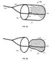
- FIG. 3Aillustrates another variation of a device where the wires 204 diverge from an end of the device 200 to form a basket 226 shape or structure.
- the basket structure 226may also be referred to as a filter or surrounding portion.
- the basket 226is sufficiently permeable to allow blood flow therethrough.
- basket 226may be any structure that covers, encapsulates, engulfs, and/or ensnares the obstruction either fully or partially. Accordingly, although the basket 226 is illustrated as a filter/bag, the wires may diverge to form a coil, helical shape, other mesh structure, or any other structure that may translate or remove the obstruction 2 once the frictional component is addressed.
- FIG. 3Bshows a top view of a variation of a device 200 showing another configuration of a basket shape 226 formed by wires that diverge from an end of the device 200 .
- the wires 204diverge in subsets 228 from the third shaped section 224 .
- the subsets 228continue to diverge at the far end of the device to form a mesh region 230 (i.e., an area of dense wire coverage).
- This mesh region 230can increase the contact area between the wires 204 and the obstruction, which assists in removal of the obstruction. Divergence of wires could occur multiple times as wires head to the distal region of basket, creating a basket with denser and denser coverage moving distally.
- FIG. 3Cdepicts a variation of the device similar to that of FIG. 3A .
- the device 200is deployed distally to the obstruction 2 .
- this deploymentallows the subsets of wires that extend along the device 200 to expand within the vessel 6 prior to contacting the occlusion 2 .
- the device 200is pulled over the occlusion 2 .
- the subsets of wires that form the second shaped portion 220addresses the frictional forces that act between the obstruction and the vessel wall.
- Conventional devices that provide a bag attached to a wireare typically unable to remove the obstruction because they cannot overcome these frictional forces that lodge the clot against the vessel wall.
- vascular filter or distal protection deviceare typically unable to remove the obstruction because they cannot overcome these frictional forces that lodge the clot against the vessel wall.
- such conventional devicesare only designed to “catch” free floating clots. Providing low friction with respect to the clot and the vessel allows for positioning of the device without disrupting or further compacting the clot against the vessel wall.
- the wires of the devicesurround or are spaced about the obstruction, they reduce the friction between the clot and vessel wall by reducing points of contact. Once these wires surround the clot, they permit translation of the device to permit a basket shaped section 226 to surround the obstruction for removal. Eventually, the device 200 is pulled so that the basket shaped section 226 captures the obstruction 2 allowing it to be removed.
- FIG. 4Aillustrates a variation of a device 200 where the first shaped section is a loop shaped member 206 and the third shaped section 224 forms a closed end where the wires converge.
- subsets 212 , 214 , 216 , 218diverge from the first shaped section 206 and extend substantially parallel to the loop. Rather than converging to form another loop, the subsets converge to form a shaped section 224 having a closed end configuration.
- FIG. 4Billustrates the variation of FIG. 4A after it converts to a high friction mode over the obstruction 2 via rotation of the first shaped section 206 .
- the number of subsetsmay vary as needed.
- the subsets of wires 212 , 214 , 216 , 218can further diverge to form a denser mesh pattern at or towards the third shaped section 224 .
- rotation of the shaped section 206forms a twist point 116 proximal to the obstruction 2 .
- the subsets of wires 212 , 214 , 216 , 218can experience some twisting and may not remain parallel.
- the rotation of the shaped section 206 as well as the twist point 116causes the subsets of wires 212 , 214 , 216 , 218 to exert a compressive force on the obstruction 2 without crossing one another over the length of the obstruction.
- the compressive action of the subsets of wires onto the obstructionconverts the device 200 to a high friction mode on the obstruction.
- FIG. 5shows one example of a method for constructing devices according to the present invention.
- a main bundle of wires 202is brought into a fixture (not shown). The fixture permits routing of the wires in the pattern as shown.
- the main bundlecomprises 8 wires.
- number of wiresis intended for exemplary purposes only. Clearly, any number of wires may be used.
- the wiresdiverge in the region marked 232 to form four separate subsets of wires 212 , 214 , 216 , 218 .
- each subset of wirecomprises 2 individual wires. This configuration is for illustrative purposes as the number of wires in each subset is not required to be the same for all.
- the wiresconverge in the region marked as 234 . It is noted that if the device is constructed on a planar fixture, the wires (once oriented) will be wrapped around a cylindrical structure and heat set to impart the shapes shown above. Accordingly, the regions marked by 232 and 234 assume partial loop shapes as the planar wire assembly is wrapped around the cylindrical fixture. In alternate variations, the wires may be oriented on a cylindrical fixture and heat set into a final shape. Doing so obviously eliminates the need to wrap the planar wire assembly about a cylindrical structure.
- the wiresform the region marked as 234 , they diverge once again to form a basket shaped section or filter 226 as discussed above. Accordingly, upon wrapping the device wires, the region marked as 234 assumes a loop shaped section.
- the wires forming the basket shaped section or filter 226can either terminate at the end of the basket or filter 226 . Alternatively, the wires can be looped around such that they eventually extend back through the main bundle 202 or loop back and terminate in any portion of the device.
- the individual wires 204may themselves comprise a bundle of smaller wires or filaments.
- the wirescan be selected from materials such as stainless steel, titanium, platinum, gold, iridium, tantalum, nitinol, and/or polymeric strands.
- the wires used in a devicemay comprise a heterogeneous structure by using combinations of wires of different materials to produce a device having the particular desired properties.
- one or more wires in the devicemay comprise a shape memory or superelastic alloy to impart predetermined shapes or resiliency to the device.
- the mechanical properties of select wirescan be altered. In such a case, the select wires can be treated to alter properties including: brittleness, ductility, elasticity, hardness, malleability, plasticity, strength, and toughness.
- the devicemay include a number of radiopaque wires, such as gold and platinum for improved visibility under fluoroscopic imaging.
- radiopaque wiressuch as gold and platinum for improved visibility under fluoroscopic imaging.
- any combination of materialsmay be incorporated into the device.
- the size of the wiresmay vary as needed.
- the diameters of the wiresmay be the same or may vary as needed.
- the individual wiresmay have cross-sectional shapes ranging from circular, oval, d-shaped, rectangular shape, etc.
- the deviceis not limited to having wires having the same cross-sectional shape. Instead, the device can have wires having different cross-sectional shapes.
- a devicecan have 8-12 wires made of 0.003′′ round superelastic material (e.g., nitinol).
- the devicemay additionally have 2-4 wires made from 0.002′′ platinum for fluoroscopy. Of the 8-12 nitinol wires, 1-4 of these wires can be made of a larger diameter or different cross-section to increase the overall strength of the device.
- a couple of polymer fiberscan be added where the fibers have a desired surface property for clot adherence, etc.
- Such a combination of wiresprovides a composite device with properties not conventionally possible in view of other formation means (such as laser cutting or etching the shape from a tube or joining materials with welds, etc.).
- any number of permutationsis possible given the principles of the invention.
- the devicemay be fabricated from wires formed from a polymeric material or composite blend of polymeric materials.
- the polymeric compositecan be selected such that it is very floppy until it is exposed to either the body fluids and or some other delivered activator that causes the polymer to further polymerize or stiffen for strength.
- Various coatingscould protect the polymer from further polymerizing before the device is properly placed.
- the coatingscould provide a specific duration for placement (e.g., 5 minutes) after which the covering degrades or is activated with an agent (that does't affect the surrounding tissues) allowing the device to increase in stiffness so that it does't stretch as the thrombus is pulled out.
- shape memory polymerswould allow the device to increase in stiffness.
- the shaped section connectorsmay be other structures than loops.
- variations of the inventioninclude connectors that may be drawn down to a smaller size to facilitate removal from the body after securing the obstruction. This may be accomplished by torquing the device or part thereof, by re-sheathing part or all of the device or by any mechanical means designed into the features of the device itself. Any of these actions, or combination thereof, may also serve to compress or decrease the diameter of the obstruction itself to facilitate removal from the body.
- the shaped portionsare formed in a loop or partial loop shape.
- the connectorsmay also comprise various alternate shapes (e.g., a circle, an arcuate shape, a partial circular shape, a loop, an oval, a square, a rectangle, a polygon, an overlapping loop, a pair of semi-circles, a flower shape, and a figure 8, other shapes, etc.)
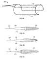
- FIGS. 6A to 6Dillustrate some possible shapes for use in the device.
- the various shapesmay be heat set to be either self expanding (i.e., superelastic) or the use of shape memory alloys can allow for the device to assume the particular shape upon reaching a desired transition temperature.
- such a shapemay be formed by a single bundle or by one or more separate portions of wire that diverge from the main bundle.
- FIG. 6Aillustrates a main bundle of wires 202 that diverge in three arcuate shaped portions 242 , 244 , 246 .
- the devicemay have more or less arcuate shaped sections.
- the segments forming the arcuate 242 , 244 , 246 shaped portionsmay simply bend to form segments that traverse across the device (as shown above.) However, such traversing sections are omitted to illustrate the arcuate shape.
- FIG. 6Billustrates a main bundle 202 that ultimately diverges to form an overlapping loop shape 248 .
- the ends of the overlapping loopmay then proceed to form the traversing subsets 212 , 214 discussed above.
- additional subsets of wiresmay diverge from a location other than the end of the overlapping loop shape 248 .
- FIG. 6Cillustrates a main bundle that diverges to form two semi-circular or partial circular shapes 250 , 252 .
- the two shapesare located along the same axial section of the device but the shapes are separate. Again, the ends of the partial circular shapes 250 , 252 may diverge to form the traversing section of the device. Alternatively, the traversing wires can come from other locations.
- FIG. 6Dillustrates a main bundle 202 that diverges to form a “figure-8” shape.
- additional subsets (not shown) of wiresmay diverge from the “figure-8” shape to form the traversing subsets.
- flower shaped sectionsmay be formed by the use of additional circular shapes that form the petals of the flower shape or via the use of multiple “figure-8” shapes.
- a devicemay have different shaped sections on different ends of the device.
- the shapeswill depend upon the ultimate application of the device. As noted herein, the illustrated examples have particular applicability in retrieving obstructions from the vasculature. Accordingly, for these applications the shaped sections should form a shape so that they can expand against a vessel wall without causing trauma to the vessel. For example, upon release from the catheter, the shaped section can assume their resting shape and expand within the vessel. The resting shape can be constructed to have a size slightly greater than that of the vessel. Sizing the device relative to the target vessel may assist in placing the parts of the device against a vessel.
- the shaped sectionsmay be designed to have an unconstrained shape that is larger than the intended target vessel or simply different than a cross sectional profile of the intended vessel (i.e., not circular or tubular, but e.g., linear or other different shape).
- the shape sectionattempts to return to the unconstrained shape.
- the leading wireassumes a shape that accommodates the vessel but is more rigid and stable since its unconstrained shape is entirely different from that of the vessel. In other words, the shaped section continually exerts an outward force on the vessel.
- the shaped sections shown hereinmay not necessarily lie in the same plane. Instead, they can be axially spaced by an offset.
- One benefit of constructing the device to have non-planar shaped sectionis that the configuration might allow for delivery of the device delivered via a smaller microcatheter because the shaped sections do not interfere with one another when collapsed to fit within the microcatheter.
- Another aspect applicable to all variations of the devicesis to configure the devices (whether the traversing filament or the surrounding portion) for better adherence to the obstruction.
- One such modeincludes the use of coatings that bond to certain clots (or other materials causing the obstruction.)
- the wiresmay be coated with a hydrogel or adhesive that bonds to a thrombus. Accordingly, as the device secures about a clot, the combination of the additive and the mechanical structure of the device may improve the effectiveness of the device in removing the obstruction.
- the traversing membersmay have hooks, fibers, or barbs 154 that grip into the obstruction when the device converts to a high friction mode.
- the hooks, fibers, or barbs 154incorporated into any portion of the device.
- the devicecan be coupled to an RF or other power source (such as 14 or 16 in FIG. 1 ), to allow current, ultrasound or RF energy to transmit through the device and induce clotting or cause additional coagulation of a clot or other the obstruction.
- an RF or other power sourcesuch as 14 or 16 in FIG. 1
- the methods described hereinmay also include treating the obstruction prior to attempting to remove the obstruction.
- a treatmentcan include applying a chemical or pharmaceutical agent with the goal of making the occlusion shrink or to make it more rigid for easier removal.
- agentsinclude, but are not limited to chemotherapy drugs, or solutions, a mild formalin, or aldehyde solution.
- the devices and methods described hereinmay also be useful in removing obstructions lodged within bifurcations in the anatomy.
- bifurcationsgreatly increase the frictional forces on the obstructions since the obstruction tends to be lodged in both branching sections of the bifurcation.
- the use of the presently described devices and methodsmay also include an additional “puller” device that advances beyond the portion of the obstruction partially located in the bifurcated vessel.
- FIGS. 7A to 7Cillustrate additional variations of obstruction removal devices.
- the wiresmay diverge from the main wire bundle 202 to form any number of shapes and structures and specifically not form loop or the shaped sections discussed above.
- the wiresdiverge to ultimately form a basket or filter shape 226 .
- FIGS. 8A to 8Fillustrate various additional configurations for construction of join-less devices 200 .
- the main bundle of wires 202diverges so that one or more wires forms the illustrated shapes.
- FIGS. 9A to 9Cshow another variation of a medical device according to the principles of the invention.
- the device 200comprises a first and second main bundles 202 , where the main bundles comprise a plurality of wires.
- the devicesfurther include a first shape and second shapes 206 formed by a divergence of the plurality of wires into a plurality of individual first subsets of wires.
- the wiresdiverge to form a network of individual single wires as shown in region 226 .
- the shapesform a three dimensional structure that is useful for removal of obstruction from within the body.
- each shapecomprises a structure that forms a portion of the basket where a network of wires forms an end of the basket.
- the network of wiresforms the entire basket.
- the shapes 206may range from a circle, an arcuate shape, a partial circular shape, a loop, an oval, a square, a rectangle, a polygon, an overlapping loop, a pair of semi-circles, a flower shape, and a figure 8 (as shown above).
Landscapes
- Health & Medical Sciences (AREA)
- Life Sciences & Earth Sciences (AREA)
- Surgery (AREA)
- Biomedical Technology (AREA)
- General Health & Medical Sciences (AREA)
- Engineering & Computer Science (AREA)
- Heart & Thoracic Surgery (AREA)
- Veterinary Medicine (AREA)
- Public Health (AREA)
- Animal Behavior & Ethology (AREA)
- Medical Informatics (AREA)
- Nuclear Medicine, Radiotherapy & Molecular Imaging (AREA)
- Molecular Biology (AREA)
- Vascular Medicine (AREA)
- Orthopedic Medicine & Surgery (AREA)
- Oral & Maxillofacial Surgery (AREA)
- Cardiology (AREA)
- Transplantation (AREA)
- Surgical Instruments (AREA)
- Media Introduction/Drainage Providing Device (AREA)
Abstract
Description
Claims (11)
Priority Applications (1)
| Application Number | Priority Date | Filing Date | Title |
|---|---|---|---|
| US13/967,203US9271748B2 (en) | 2007-04-17 | 2013-08-14 | Complex wire formed devices |
Applications Claiming Priority (3)
| Application Number | Priority Date | Filing Date | Title |
|---|---|---|---|
| US11/736,526US8535334B2 (en) | 2007-04-17 | 2007-04-17 | Complex wire formed devices |
| US11/736,537US8512352B2 (en) | 2007-04-17 | 2007-04-17 | Complex wire formed devices |
| US13/967,203US9271748B2 (en) | 2007-04-17 | 2013-08-14 | Complex wire formed devices |
Related Parent Applications (1)
| Application Number | Title | Priority Date | Filing Date |
|---|---|---|---|
| US11/736,526ContinuationUS8535334B2 (en) | 2007-04-17 | 2007-04-17 | Complex wire formed devices |
Publications (2)
| Publication Number | Publication Date |
|---|---|
| US20140148841A1 US20140148841A1 (en) | 2014-05-29 |
| US9271748B2true US9271748B2 (en) | 2016-03-01 |
Family
ID=39875896
Family Applications (4)
| Application Number | Title | Priority Date | Filing Date |
|---|---|---|---|
| US11/736,526Expired - Fee RelatedUS8535334B2 (en) | 2007-04-17 | 2007-04-17 | Complex wire formed devices |
| US11/736,537Expired - Fee RelatedUS8512352B2 (en) | 2007-04-17 | 2007-04-17 | Complex wire formed devices |
| US13/946,901ActiveUS9271747B2 (en) | 2007-04-17 | 2013-07-19 | Complex wire formed devices |
| US13/967,203Expired - Fee RelatedUS9271748B2 (en) | 2007-04-17 | 2013-08-14 | Complex wire formed devices |
Family Applications Before (3)
| Application Number | Title | Priority Date | Filing Date |
|---|---|---|---|
| US11/736,526Expired - Fee RelatedUS8535334B2 (en) | 2007-04-17 | 2007-04-17 | Complex wire formed devices |
| US11/736,537Expired - Fee RelatedUS8512352B2 (en) | 2007-04-17 | 2007-04-17 | Complex wire formed devices |
| US13/946,901ActiveUS9271747B2 (en) | 2007-04-17 | 2013-07-19 | Complex wire formed devices |
Country Status (3)
| Country | Link |
|---|---|
| US (4) | US8535334B2 (en) |
| EP (1) | EP2142103B1 (en) |
| WO (1) | WO2008131116A1 (en) |
Cited By (3)
| Publication number | Priority date | Publication date | Assignee | Title |
|---|---|---|---|---|
| US20160174996A1 (en)* | 2007-04-17 | 2016-06-23 | Lazarus Effect, Inc. | Complex wire formed devices |
| US11383068B2 (en) | 2018-07-20 | 2022-07-12 | eLum Technologies, Inc. | Neurovascular distal access support catheters, aspiration catheters, or device shafts |
| US11399853B2 (en) | 2018-05-30 | 2022-08-02 | eLum Technologies, Inc. | Integrated thrombectomy and filter device and methods of use |
Families Citing this family (123)
| Publication number | Priority date | Publication date | Assignee | Title |
|---|---|---|---|---|
| US8425549B2 (en) | 2002-07-23 | 2013-04-23 | Reverse Medical Corporation | Systems and methods for removing obstructive matter from body lumens and treating vascular defects |
| US7686825B2 (en) | 2004-03-25 | 2010-03-30 | Hauser David L | Vascular filter device |
| EP1986568B1 (en) | 2006-02-03 | 2017-04-05 | Covidien LP | Methods and devices for restoring blood flow within blocked vasculature |
| US20080269774A1 (en) | 2006-10-26 | 2008-10-30 | Chestnut Medical Technologies, Inc. | Intracorporeal Grasping Device |
| US11202646B2 (en) | 2007-04-17 | 2021-12-21 | Covidien Lp | Articulating retrieval devices |
| US8535334B2 (en) | 2007-04-17 | 2013-09-17 | Lazarus Effect, Inc. | Complex wire formed devices |
| US10064635B2 (en)* | 2007-04-17 | 2018-09-04 | Covidien Lp | Articulating retrieval devices |
| US8613753B2 (en) | 2007-08-31 | 2013-12-24 | BiO2 Medical, Inc. | Multi-lumen central access vena cava filter apparatus and method of using same |
| US8668712B2 (en) | 2007-08-31 | 2014-03-11 | BiO2 Medical, Inc. | Multi-lumen central access vena cava filter apparatus and method of using same |
| US8088140B2 (en) | 2008-05-19 | 2012-01-03 | Mindframe, Inc. | Blood flow restorative and embolus removal methods |
| US8066757B2 (en) | 2007-10-17 | 2011-11-29 | Mindframe, Inc. | Blood flow restoration and thrombus management methods |
| US9220522B2 (en) | 2007-10-17 | 2015-12-29 | Covidien Lp | Embolus removal systems with baskets |
| US9198687B2 (en) | 2007-10-17 | 2015-12-01 | Covidien Lp | Acute stroke revascularization/recanalization systems processes and products thereby |
| US11337714B2 (en) | 2007-10-17 | 2022-05-24 | Covidien Lp | Restoring blood flow and clot removal during acute ischemic stroke |
| US10123803B2 (en) | 2007-10-17 | 2018-11-13 | Covidien Lp | Methods of managing neurovascular obstructions |
| US8926680B2 (en) | 2007-11-12 | 2015-01-06 | Covidien Lp | Aneurysm neck bridging processes with revascularization systems methods and products thereby |
| US8585713B2 (en) | 2007-10-17 | 2013-11-19 | Covidien Lp | Expandable tip assembly for thrombus management |
| US8545526B2 (en) | 2007-12-26 | 2013-10-01 | Lazarus Effect, Inc. | Retrieval systems and methods for use thereof |
| US20150164630A1 (en)* | 2008-01-04 | 2015-06-18 | Eric Johnson | Filter support members |
| JP5457373B2 (en) | 2008-02-22 | 2014-04-02 | コヴィディエン リミテッド パートナーシップ | Device for blood flow recovery |
| CN101977650A (en) | 2008-04-11 | 2011-02-16 | 曼德弗雷姆公司 | Monorail neural microcatheter for delivery of medical device for treatment of stroke, methods and products thereof |
| EP2341845B1 (en) | 2008-07-22 | 2016-01-06 | Neuravi Limited | Clot capture systems |
| US9402707B2 (en) | 2008-07-22 | 2016-08-02 | Neuravi Limited | Clot capture systems and associated methods |
| EP2403583B1 (en) | 2009-03-06 | 2016-10-19 | Lazarus Effect, Inc. | Retrieval systems |
| US8568433B2 (en)* | 2009-07-10 | 2013-10-29 | Cook Medical Technologies Llc | Medical device having one or more active strands |
| US20110137334A1 (en)* | 2009-12-04 | 2011-06-09 | Boston Scientific Scimed, Inc. | Electroactively Deployed Filter Device |
| EP2525861B1 (en) | 2010-01-22 | 2019-04-03 | Covidien LP | Retrieval systems |
| EP2533698B1 (en) | 2010-02-11 | 2018-03-28 | Boston Scientific Scimed, Inc. | Automatic vascular closure deployment devices |
| AU2011217844B2 (en)* | 2010-02-18 | 2014-09-25 | BiO2 Medical, Inc. | Vena cava filter catheter and method |
| AU2013205337B2 (en)* | 2010-02-18 | 2015-04-16 | BiO2 Medical, Inc. | Vena cava filter catheter and method |
| CA2804254C (en)* | 2010-02-23 | 2016-11-01 | Medina Medical, Inc. | Devices and methods for vascular recanalization |
| DE102010010849B4 (en)* | 2010-03-10 | 2024-10-02 | Acandis Gmbh | Medical device for removing concretions from hollow body organs and method for producing such a device |
| WO2012009675A2 (en) | 2010-07-15 | 2012-01-19 | Lazarus Effect, Inc. | Retrieval systems and methods for use thereof |
| US9414821B2 (en) | 2010-07-22 | 2016-08-16 | Boston Scientific Scimed, Inc. | Vascular closure device with biodegradable anchor |
| ES2683943T3 (en) | 2010-10-22 | 2018-09-28 | Neuravi Limited | Clot capture and removal system |
| US8758402B2 (en) | 2010-12-17 | 2014-06-24 | Boston Scientific Scimed, Inc. | Tissue puncture closure device |
| KR101298690B1 (en)* | 2011-01-25 | 2013-08-21 | 신경민 | Medical Snare |
| EP4566553A3 (en) | 2011-03-09 | 2025-08-06 | Neuravi Limited | A clot retrieval device for removing occlusive clot from a blood vessel |
| US11259824B2 (en) | 2011-03-09 | 2022-03-01 | Neuravi Limited | Clot retrieval device for removing occlusive clot from a blood vessel |
| US12076037B2 (en) | 2011-03-09 | 2024-09-03 | Neuravi Limited | Systems and methods to restore perfusion to a vessel |
| DE102011014586B3 (en)* | 2011-03-21 | 2012-09-13 | Acandis Gmbh & Co. Kg | Medical device for treatment of hollow organs of the body, system with such a device and method for producing such a device |
| ES2683178T3 (en) | 2011-05-23 | 2018-09-25 | Covidien Lp | Extraction systems |
| US8968354B2 (en)* | 2011-10-26 | 2015-03-03 | Boston Scientific Scimed, Inc. | Extended protection embolic filter |
| US20140309673A1 (en)* | 2011-11-11 | 2014-10-16 | Nathan John Dacuycuy | Devices for removing vessel occlusions |
| WO2014047650A1 (en) | 2012-09-24 | 2014-03-27 | Inceptus Medical LLC | Device and method for treating vascular occlusion |
| US8784434B2 (en) | 2012-11-20 | 2014-07-22 | Inceptus Medical, Inc. | Methods and apparatus for treating embolism |
| US9119948B2 (en) | 2013-02-20 | 2015-09-01 | Covidien Lp | Occlusive implants for hollow anatomical structures, delivery systems, and related methods |
| US9271818B2 (en) | 2013-02-25 | 2016-03-01 | Cook Medical Technologies Llc | Conical vena cava filter with jugular or femoral retrieval |
| US9642635B2 (en) | 2013-03-13 | 2017-05-09 | Neuravi Limited | Clot removal device |
| US20140276403A1 (en) | 2013-03-13 | 2014-09-18 | DePuy Synthes Products, LLC | Ischemic stroke device |
| ES2708786T3 (en) | 2013-03-14 | 2019-04-11 | Neuravi Ltd | Clot recovery device to remove occlusive clots from a blood vessel |
| US9433429B2 (en) | 2013-03-14 | 2016-09-06 | Neuravi Limited | Clot retrieval devices |
| WO2014140092A2 (en) | 2013-03-14 | 2014-09-18 | Neuravi Limited | Devices and methods for removal of acute blockages from blood vessels |
| WO2014141226A1 (en) | 2013-03-15 | 2014-09-18 | National University Of Ireland | A device suitable for removing matter from inside the lumen and the wall of a body lumen |
| US10238406B2 (en) | 2013-10-21 | 2019-03-26 | Inari Medical, Inc. | Methods and apparatus for treating embolism |
| US10285720B2 (en) | 2014-03-11 | 2019-05-14 | Neuravi Limited | Clot retrieval system for removing occlusive clot from a blood vessel |
| CN106470728A (en) | 2014-06-09 | 2017-03-01 | 因赛普特斯医学有限责任公司 | Retraction and suction device and related systems and methods for treating embolism |
| JP6595513B2 (en) | 2014-06-13 | 2019-10-23 | ニューラヴィ・リミテッド | Device for removal of acute occlusions from blood vessels |
| US10792056B2 (en) | 2014-06-13 | 2020-10-06 | Neuravi Limited | Devices and methods for removal of acute blockages from blood vessels |
| US10265086B2 (en) | 2014-06-30 | 2019-04-23 | Neuravi Limited | System for removing a clot from a blood vessel |
| EP3682821B1 (en) | 2014-11-26 | 2022-05-11 | Neuravi Limited | A clot retrieval device for removing an occlusive clot from a blood vessel |
| US10617435B2 (en) | 2014-11-26 | 2020-04-14 | Neuravi Limited | Clot retrieval device for removing clot from a blood vessel |
| US11253278B2 (en) | 2014-11-26 | 2022-02-22 | Neuravi Limited | Clot retrieval system for removing occlusive clot from a blood vessel |
| CN104434263A (en)* | 2014-12-01 | 2015-03-25 | 中国人民解放军第二军医大学 | Regulating intracranial intravascular thrombus extraction device |
| JP2018504238A (en)* | 2015-02-06 | 2018-02-15 | ラピッド メディカル リミテッド | System and method for removing intravascular obstructions |
| EP3256200A1 (en) | 2015-02-11 | 2017-12-20 | Covidien LP | Expandable tip medical devices and methods |
| US9744024B2 (en)* | 2015-08-06 | 2017-08-29 | Kp Medcure, Inc. | Axial lengthening thrombus capture system |
| US9579116B1 (en)* | 2015-08-06 | 2017-02-28 | Kp Medcure, Inc. | Axial lengthening thrombus capture system |
| WO2017062383A1 (en)* | 2015-10-07 | 2017-04-13 | Stryker Corporation | Multiple barrel clot removal devices |
| US10342571B2 (en) | 2015-10-23 | 2019-07-09 | Inari Medical, Inc. | Intravascular treatment of vascular occlusion and associated devices, systems, and methods |
| CN113796927B (en) | 2015-10-23 | 2025-03-04 | 伊纳里医疗公司 | Intravascular treatment of vascular occlusion and related devices, systems and methods |
| US9700332B2 (en) | 2015-10-23 | 2017-07-11 | Inari Medical, Inc. | Intravascular treatment of vascular occlusion and associated devices, systems, and methods |
| CN115300748A (en) | 2015-12-18 | 2022-11-08 | 伊纳里医疗有限公司 | Catheter shaft and related devices, systems and methods |
| US10542964B2 (en)* | 2016-05-25 | 2020-01-28 | Medtronic, Inc. | Interventional medical device retrieval |
| EP3500191B1 (en) | 2016-08-17 | 2020-09-23 | Neuravi Limited | A clot retrieval system for removing occlusive clot from a blood vessel |
| EP3509509B1 (en) | 2016-09-06 | 2021-03-31 | Neuravi Limited | A clot retrieval device for removing occlusive clot from a blood vessel |
| FR3057758B1 (en)* | 2016-10-20 | 2022-01-28 | Stsat Ag | SYSTEM FOR EXTRACTING THE THROMBOEMBOLIC SUBSTANCE PRESENT IN A BLOOD VESSEL |
| FI3528717T3 (en) | 2016-10-24 | 2024-08-09 | Inari Medical Inc | Devices for treating vascular occlusion |
| US11129630B2 (en) | 2017-05-12 | 2021-09-28 | Covidien Lp | Retrieval of material from vessel lumens |
| US11191555B2 (en) | 2017-05-12 | 2021-12-07 | Covidien Lp | Retrieval of material from vessel lumens |
| US10709464B2 (en) | 2017-05-12 | 2020-07-14 | Covidien Lp | Retrieval of material from vessel lumens |
| US11298145B2 (en) | 2017-05-12 | 2022-04-12 | Covidien Lp | Retrieval of material from vessel lumens |
| US10722257B2 (en) | 2017-05-12 | 2020-07-28 | Covidien Lp | Retrieval of material from vessel lumens |
| WO2018232044A1 (en) | 2017-06-12 | 2018-12-20 | Covidien Lp | Tools for sheathing treatment devices and associated systems and methods |
| US10478322B2 (en) | 2017-06-19 | 2019-11-19 | Covidien Lp | Retractor device for transforming a retrieval device from a deployed position to a delivery position |
| US10575864B2 (en) | 2017-06-22 | 2020-03-03 | Covidien Lp | Securing element for resheathing an intravascular device and associated systems and methods |
| WO2019050765A1 (en) | 2017-09-06 | 2019-03-14 | Inari Medical, Inc. | Hemostasis valves and methods of use |
| US11154314B2 (en) | 2018-01-26 | 2021-10-26 | Inari Medical, Inc. | Single insertion delivery system for treating embolism and associated systems and methods |
| CA3114285A1 (en) | 2018-08-13 | 2020-02-20 | Inari Medical, Inc. | System for treating embolism and associated devices and methods |
| US10842498B2 (en) | 2018-09-13 | 2020-11-24 | Neuravi Limited | Systems and methods of restoring perfusion to a vessel |
| US11406416B2 (en) | 2018-10-02 | 2022-08-09 | Neuravi Limited | Joint assembly for vasculature obstruction capture device |
| WO2020087009A1 (en)* | 2018-10-26 | 2020-04-30 | Progressive NEURO, Inc. | Apparatus, system, and method for vasculature obstruction removal |
| ES2910600T3 (en) | 2019-03-04 | 2022-05-12 | Neuravi Ltd | Powered Clot Recovery Catheter |
| US11109939B2 (en) | 2019-06-14 | 2021-09-07 | DePuy Synthes Products, Inc. | Intravascular devices with radiopaque body markers |
| EP3791815B1 (en) | 2019-09-11 | 2024-06-26 | Neuravi Limited | Expandable mouth catheter |
| JP7638273B2 (en) | 2019-10-16 | 2025-03-03 | イナリ メディカル, インコーポレイテッド | Systems, devices and methods for treating vascular obstructions |
| US11712231B2 (en) | 2019-10-29 | 2023-08-01 | Neuravi Limited | Proximal locking assembly design for dual stent mechanical thrombectomy device |
| CN115175638B (en) | 2019-11-05 | 2025-09-26 | 瓦斯科尔勒治疗股份有限公司 | Axially extended thrombus capture system, tensioning system, and expandable funnel catheter |
| US11779364B2 (en) | 2019-11-27 | 2023-10-10 | Neuravi Limited | Actuated expandable mouth thrombectomy catheter |
| US11839725B2 (en) | 2019-11-27 | 2023-12-12 | Neuravi Limited | Clot retrieval device with outer sheath and inner catheter |
| US11517340B2 (en) | 2019-12-03 | 2022-12-06 | Neuravi Limited | Stentriever devices for removing an occlusive clot from a vessel and methods thereof |
| US11944327B2 (en) | 2020-03-05 | 2024-04-02 | Neuravi Limited | Expandable mouth aspirating clot retrieval catheter |
| US11633198B2 (en) | 2020-03-05 | 2023-04-25 | Neuravi Limited | Catheter proximal joint |
| US11883043B2 (en) | 2020-03-31 | 2024-01-30 | DePuy Synthes Products, Inc. | Catheter funnel extension |
| US11759217B2 (en) | 2020-04-07 | 2023-09-19 | Neuravi Limited | Catheter tubular support |
| US11730501B2 (en) | 2020-04-17 | 2023-08-22 | Neuravi Limited | Floating clot retrieval device for removing clots from a blood vessel |
| US11871946B2 (en) | 2020-04-17 | 2024-01-16 | Neuravi Limited | Clot retrieval device for removing clot from a blood vessel |
| US11717308B2 (en) | 2020-04-17 | 2023-08-08 | Neuravi Limited | Clot retrieval device for removing heterogeneous clots from a blood vessel |
| US11737771B2 (en) | 2020-06-18 | 2023-08-29 | Neuravi Limited | Dual channel thrombectomy device |
| US11937836B2 (en) | 2020-06-22 | 2024-03-26 | Neuravi Limited | Clot retrieval system with expandable clot engaging framework |
| US11439418B2 (en) | 2020-06-23 | 2022-09-13 | Neuravi Limited | Clot retrieval device for removing clot from a blood vessel |
| US11395669B2 (en) | 2020-06-23 | 2022-07-26 | Neuravi Limited | Clot retrieval device with flexible collapsible frame |
| US11864781B2 (en) | 2020-09-23 | 2024-01-09 | Neuravi Limited | Rotating frame thrombectomy device |
| KR20230107573A (en)* | 2020-10-12 | 2023-07-17 | 테루모 코퍼레이션 | Pulmonary embolization system |
| US11937837B2 (en) | 2020-12-29 | 2024-03-26 | Neuravi Limited | Fibrin rich / soft clot mechanical thrombectomy device |
| US12029442B2 (en) | 2021-01-14 | 2024-07-09 | Neuravi Limited | Systems and methods for a dual elongated member clot retrieval apparatus |
| US11872354B2 (en) | 2021-02-24 | 2024-01-16 | Neuravi Limited | Flexible catheter shaft frame with seam |
| US12064130B2 (en) | 2021-03-18 | 2024-08-20 | Neuravi Limited | Vascular obstruction retrieval device having sliding cages pinch mechanism |
| US11974764B2 (en) | 2021-06-04 | 2024-05-07 | Neuravi Limited | Self-orienting rotating stentriever pinching cells |
| CN113693676A (en)* | 2021-08-24 | 2021-11-26 | 北京泰杰伟业科技有限公司 | Adjustable thrombectomy device |
| US11937839B2 (en) | 2021-09-28 | 2024-03-26 | Neuravi Limited | Catheter with electrically actuated expandable mouth |
| US12011186B2 (en) | 2021-10-28 | 2024-06-18 | Neuravi Limited | Bevel tip expandable mouth catheter with reinforcing ring |
| EP4463083A1 (en) | 2022-01-11 | 2024-11-20 | Inari Medical, Inc. | Devices for removing clot material from intravascularly implanted devices, and associated systems and methods |
Citations (191)
| Publication number | Priority date | Publication date | Assignee | Title |
|---|---|---|---|---|
| US2918919A (en) | 1957-04-19 | 1959-12-29 | American Cystoscope Makers Inc | Combined ureteral stone remover and drain |
| US2943626A (en) | 1957-01-31 | 1960-07-05 | Dormia Enrico | Instruments for the extraction of foreign bodies |
| US3996938A (en) | 1975-07-10 | 1976-12-14 | Clark Iii William T | Expanding mesh catheter |
| US4347846A (en) | 1979-12-07 | 1982-09-07 | Porges | Surgical extractor |
| US4611594A (en) | 1984-04-11 | 1986-09-16 | Northwestern University | Medical instrument for containment and removal of calculi |
| DE3501707C2 (en) | 1985-01-19 | 1987-01-02 | Georg 3008 Garbsen Pauldrach | Device for recovering or dissecting concretions formed in human hollow organs |
| JPS6249841U (en) | 1985-09-18 | 1987-03-27 | ||
| US4699147A (en) | 1985-09-25 | 1987-10-13 | Cordis Corporation | Intraventricular multielectrode cardial mapping probe and method for using same |
| US4790812A (en) | 1985-11-15 | 1988-12-13 | Hawkins Jr Irvin F | Apparatus and method for removing a target object from a body passsageway |
| US4807626A (en) | 1985-02-14 | 1989-02-28 | Mcgirr Douglas B | Stone extractor and method |
| US4832055A (en) | 1988-07-08 | 1989-05-23 | Palestrant Aubrey M | Mechanically locking blood clot filter |
| US4873978A (en) | 1987-12-04 | 1989-10-17 | Robert Ginsburg | Device and method for emboli retrieval |
| US4969891A (en) | 1989-03-06 | 1990-11-13 | Gewertz Bruce L | Removable vascular filter |
| US5057114A (en) | 1990-09-18 | 1991-10-15 | Cook Incorporated | Medical retrieval basket |
| US5059178A (en) | 1988-08-03 | 1991-10-22 | Ya Wang D | Method of percutaneously removing a thrombus from a blood vessel by using catheters and system for removing a thrombus from a blood vessel by using catheters |
| US5102415A (en) | 1989-09-06 | 1992-04-07 | Guenther Rolf W | Apparatus for removing blood clots from arteries and veins |
| US5147400A (en) | 1989-05-10 | 1992-09-15 | United States Surgical Corporation | Connective tissue prosthesis |
| US5152777A (en) | 1989-01-25 | 1992-10-06 | Uresil Corporation | Device and method for providing protection from emboli and preventing occulsion of blood vessels |
| US5192286A (en) | 1991-07-26 | 1993-03-09 | Regents Of The University Of California | Method and device for retrieving materials from body lumens |
| US5300086A (en) | 1990-01-19 | 1994-04-05 | Pierre Gory | Device with a locating member for removably implanting a blood filter in a vein of the human body |
| US5443478A (en) | 1992-09-02 | 1995-08-22 | Board Of Regents, The University Of Texas System | Multi-element intravascular occlusion device |
| US5458375A (en) | 1994-04-25 | 1995-10-17 | The Anspach Effort, Inc. | Rotary connector for fluid conduits |
| WO1996001591A1 (en) | 1994-07-08 | 1996-01-25 | Microvena Corporation | Method of forming medical devices; intravascular occlusion devices |
| US5496330A (en) | 1993-02-19 | 1996-03-05 | Boston Scientific Corporation | Surgical extractor with closely angularly spaced individual filaments |
| US5509900A (en) | 1992-03-02 | 1996-04-23 | Kirkman; Thomas R. | Apparatus and method for retaining a catheter in a blood vessel in a fixed position |
| WO1996019941A1 (en) | 1994-12-23 | 1996-07-04 | New York Society For The Ruptured And Crippled Maintaining The Hospital For Special Surgery | Vena caval filter |
| US5653684A (en) | 1992-06-26 | 1997-08-05 | Schneider (Usa), Inc. | Catheter with expandable wire mesh tip |
| WO1997027893A1 (en) | 1996-02-02 | 1997-08-07 | Transvascular, Inc. | Methods and apparatus for blocking flow through blood vessels |
| WO1997027808A1 (en) | 1996-02-02 | 1997-08-07 | Regents Of The University Of California | Clot capture coil |
| US5658296A (en) | 1994-11-21 | 1997-08-19 | Boston Scientific Corporation | Method for making surgical retrieval baskets |
| US5709704A (en) | 1994-11-30 | 1998-01-20 | Boston Scientific Corporation | Blood clot filtering |
| WO1998003120A1 (en) | 1996-07-22 | 1998-01-29 | Applied Medical Resources Corporation | Access device with expandable containment member |
| US5733302A (en) | 1993-03-25 | 1998-03-31 | Hemodynamics, Inc. | Cardiovascular stent and retrieval apparatus |
| US5741325A (en) | 1993-10-01 | 1998-04-21 | Emory University | Self-expanding intraluminal composite prosthesis |
| US5792156A (en) | 1995-06-27 | 1998-08-11 | Laboratoire Perouse Implant | Instrument for vascular surgery and its use |
| US5827324A (en) | 1997-03-06 | 1998-10-27 | Scimed Life Systems, Inc. | Distal protection device |
| JPH1147140A (en) | 1997-07-29 | 1999-02-23 | Olympus Optical Co Ltd | Collecting instrument |
| US5947995A (en) | 1997-06-06 | 1999-09-07 | Samuels; Shaun Lawrence Wilkie | Method and apparatus for removing blood clots and other objects |
| US5968090A (en) | 1997-09-08 | 1999-10-19 | United States Surgical Corp. | Endovascular graft and method |
| US5972019A (en) | 1996-07-25 | 1999-10-26 | Target Therapeutics, Inc. | Mechanical clot treatment device |
| US5971938A (en) | 1996-04-02 | 1999-10-26 | Hart; Charles C. | Access device with expandable containment member |
| US6001118A (en) | 1997-03-06 | 1999-12-14 | Scimed Life Systems, Inc. | Distal protection device and method |
| US6033394A (en) | 1997-12-05 | 2000-03-07 | Intratherapeutics, Inc. | Catheter support structure |
| US6066158A (en) | 1996-07-25 | 2000-05-23 | Target Therapeutics, Inc. | Mechanical clot encasing and removal wire |
| US6066149A (en) | 1997-09-30 | 2000-05-23 | Target Therapeutics, Inc. | Mechanical clot treatment device with distal filter |
| US6096053A (en) | 1996-05-03 | 2000-08-01 | Scimed Life Systems, Inc. | Medical retrieval basket |
| US6099534A (en) | 1997-10-01 | 2000-08-08 | Scimed Life Systems, Inc. | Releasable basket |
| WO2000072909A1 (en) | 1999-06-02 | 2000-12-07 | Concentric Medical, Inc. | Devices and methods for treating vascular malformations |
| US6159220A (en) | 1999-03-11 | 2000-12-12 | Scimed Life Systems, Inc. | Medical retrieval device |
| US6165200A (en) | 1997-05-08 | 2000-12-26 | Scimed Life Systems, Inc. | Percutaneous catheter and guidewire having filter and medical device deployment capabilities |
| US6168603B1 (en) | 1995-02-02 | 2001-01-02 | Boston Scientific Corporation | Surgical extractor |
| US6174318B1 (en) | 1998-04-23 | 2001-01-16 | Scimed Life Systems, Inc. | Basket with one or more moveable legs |
| US6190394B1 (en) | 1999-11-05 | 2001-02-20 | Annex Medical, Inc. | Medical retrieval basket |
| US6217609B1 (en) | 1998-06-30 | 2001-04-17 | Schneider (Usa) Inc | Implantable endoprosthesis with patterned terminated ends and methods for making same |
| US6221006B1 (en) | 1998-02-10 | 2001-04-24 | Artemis Medical Inc. | Entrapping apparatus and method for use |
| WO2001032254A1 (en) | 1999-11-04 | 2001-05-10 | The Floundry Llc | Methods and devices for filtering fluid flow through a body structure |
| US6248113B1 (en) | 1996-06-20 | 2001-06-19 | Ernesto Fina | Device for the electrolytic dissolution of urinary stones and related method of treatment of urinary calculosis |
| US6264664B1 (en) | 2000-03-10 | 2001-07-24 | General Science And Technology Corp. | Surgical basket devices |
| WO2001067967A1 (en) | 2000-03-10 | 2001-09-20 | Radius Medical Technologies, Inc. | Surgical snare apparatus |
| US6309399B1 (en) | 1996-07-17 | 2001-10-30 | Scimed Life Systems, Inc. | Atherectomy device having trapping and excising means for removal of plaque from the aorta and other arteries |
| US20010044634A1 (en) | 2000-03-10 | 2001-11-22 | Don Michael T. Anthony | Vascular embolism prevention device employing filters |
| US20010051810A1 (en) | 1998-02-10 | 2001-12-13 | Dubrul William Richard | Tissue separation medical device and method |
| US20020002396A1 (en) | 2000-02-11 | 2002-01-03 | John Fulkerson | Apparatus and methods for delivery of intraluminal prostheses |
| US20020004667A1 (en) | 2000-05-24 | 2002-01-10 | Bruce Adams | Collapsible blood filter with optimal braid geometry |
| US6348056B1 (en) | 1999-08-06 | 2002-02-19 | Scimed Life Systems, Inc. | Medical retrieval device with releasable retrieval basket |
| US6350266B1 (en) | 1995-02-02 | 2002-02-26 | Scimed Life Systems, Inc. | Hybrid stone retrieval device |
| US20020026211A1 (en) | 1999-12-23 | 2002-02-28 | Farhad Khosravi | Vascular device having emboli and thrombus removal element and methods of use |
| US6364895B1 (en) | 1999-10-07 | 2002-04-02 | Prodesco, Inc. | Intraluminal filter |
| US6371971B1 (en) | 1999-11-15 | 2002-04-16 | Scimed Life Systems, Inc. | Guidewire filter and methods of use |
| US6383195B1 (en) | 1998-04-13 | 2002-05-07 | Endoline, Inc. | Laparoscopic specimen removal apparatus |
| US20020058904A1 (en) | 2000-11-08 | 2002-05-16 | Robert Boock | Thrombus removal device |
| US6402771B1 (en) | 1999-12-23 | 2002-06-11 | Guidant Endovascular Solutions | Snare |
| US20020072764A1 (en) | 2000-06-29 | 2002-06-13 | Concentric Medical, Inc. | Systems, method and devices for removing obstructions from a blood vessel |
| WO2002028291A3 (en) | 2000-09-29 | 2002-06-13 | Primus Medical Inc | Surgical snare apparatus |
| US6409750B1 (en) | 1999-02-01 | 2002-06-25 | Board Of Regents, The University Of Texas System | Woven bifurcated and trifurcated stents and methods for making the same |
| US6416505B1 (en) | 1998-05-05 | 2002-07-09 | Scimed Life Systems, Inc. | Surgical method and apparatus for positioning a diagnostic or therapeutic element within the body and pressure application probe for use with same |
| US6443972B1 (en) | 1997-11-19 | 2002-09-03 | Cordis Europa N.V. | Vascular filter |
| US20020123765A1 (en) | 2000-06-29 | 2002-09-05 | Concentric Medical, Inc. | Systems, methods and devices for removing obstructions from a blood vessel |
| US6458139B1 (en) | 1999-06-21 | 2002-10-01 | Endovascular Technologies, Inc. | Filter/emboli extractor for use in variable sized blood vessels |
| US20020188314A1 (en) | 2001-06-07 | 2002-12-12 | Microvena Corporation | Radiopaque distal embolic protection device |
| US6494884B2 (en) | 2001-02-09 | 2002-12-17 | Concentric Medical, Inc. | Methods and devices for delivering occlusion elements |
| US20020193825A1 (en) | 2001-06-18 | 2002-12-19 | Rex Medical | Multiple access vein filter |
| WO2003000334A1 (en) | 2001-06-26 | 2003-01-03 | Concentric Medical, Inc. | Balloon catheter |
| US6506204B2 (en) | 1996-01-24 | 2003-01-14 | Aga Medical Corporation | Method and apparatus for occluding aneurysms |
| WO2002002162A3 (en) | 2000-06-29 | 2003-01-30 | Concentric Medical Inc | Systems, methods and devices for removing obstructions from a blood vessel |
| US20030023265A1 (en) | 2001-07-13 | 2003-01-30 | Forber Simon John | Vascular protection system |
| US6514273B1 (en) | 2000-03-22 | 2003-02-04 | Endovascular Technologies, Inc. | Device for removal of thrombus through physiological adhesion |
| US20030040771A1 (en) | 1999-02-01 | 2003-02-27 | Hideki Hyodoh | Methods for creating woven devices |
| US20030050663A1 (en) | 2001-06-28 | 2003-03-13 | Stepan Khachin | Surgical device for retrieval of foreign objects from a body |
| US20030060782A1 (en) | 1998-06-04 | 2003-03-27 | Arani Bose | Endovascular thin film devices and methods for treating and preventing stroke |
| US6540657B2 (en) | 2000-12-28 | 2003-04-01 | Scimed Life Systems, Inc. | Apparatus and method for internally inducing a magnetic field in an aneurysm to embolize aneurysm with magnetically-controllable substance |
| US6551342B1 (en) | 2001-08-24 | 2003-04-22 | Endovascular Technologies, Inc. | Embolic filter |
| US20030093087A1 (en) | 2001-11-15 | 2003-05-15 | Jones Donald K. | Embolic coil retrieval system |
| US6575997B1 (en) | 1999-12-23 | 2003-06-10 | Endovascular Technologies, Inc. | Embolic basket |
| US6585753B2 (en) | 2001-03-28 | 2003-07-01 | Scimed Life Systems, Inc. | Expandable coil stent |
| US6592605B2 (en) | 1997-05-05 | 2003-07-15 | Board Of Regents, The University Of Texas System | Wire frame partial flow obstruction device for aneurysm treatment |
| US20030144687A1 (en) | 1999-05-07 | 2003-07-31 | Salviac Limited | Support frame for an embolic protection device |
| US20030153935A1 (en) | 2000-09-04 | 2003-08-14 | Claude Mialhe | Vascular occlusion device, apparatus and method for using same |
| US6610077B1 (en) | 2001-01-23 | 2003-08-26 | Endovascular Technologies, Inc. | Expandable emboli filter and thrombectomy device |
| US6616679B1 (en) | 1999-07-30 | 2003-09-09 | Incept, Llc | Rapid exchange vascular device for emboli and thrombus removal and methods of use |
| US6620148B1 (en) | 1999-08-04 | 2003-09-16 | Scimed Life Systems, Inc. | Filter flush system and methods of use |
| US20030195556A1 (en) | 2000-04-28 | 2003-10-16 | Stack Richard S. | System and device for minimizing embolic risk during an interventional procedure |
| US6635068B1 (en) | 1998-02-10 | 2003-10-21 | Artemis Medical, Inc. | Occlusion, anchoring, tensioning and flow direction apparatus and methods for use |
| US6636758B2 (en) | 2001-05-01 | 2003-10-21 | Concentric Medical, Inc. | Marker wire and process for using it |
| WO2003089039A1 (en) | 2002-04-20 | 2003-10-30 | Friedhelm Brassel | Medical retriever |
| US6645199B1 (en) | 1999-11-22 | 2003-11-11 | Scimed Life Systems, Inc. | Loop structures for supporting diagnostic and therapeutic elements contact with body tissue and expandable push devices for use with same |
| US6652548B2 (en) | 2000-03-31 | 2003-11-25 | Bacchus Vascular Inc. | Expansible shearing catheters for thrombus removal |
| US6652505B1 (en) | 1999-08-03 | 2003-11-25 | Scimed Life Systems Inc. | Guided filter with support wire and methods of use |
| US6660021B1 (en) | 1999-12-23 | 2003-12-09 | Advanced Cardiovascular Systems, Inc. | Intravascular device and system |
| US6663650B2 (en) | 2000-06-29 | 2003-12-16 | Concentric Medical, Inc. | Systems, methods and devices for removing obstructions from a blood vessel |
| US6673042B1 (en) | 1999-11-22 | 2004-01-06 | Wilfred J. Samson | Expandable venous cannula and method of use |
| US6679893B1 (en) | 2000-11-16 | 2004-01-20 | Chestnut Medical Technologies, Inc. | Grasping device and method of use |
| US6685738B2 (en) | 2000-01-31 | 2004-02-03 | Scimed Life Systems, Inc. | Braided endoluminal device having tapered filaments |
| US6702782B2 (en) | 2001-06-26 | 2004-03-09 | Concentric Medical, Inc. | Large lumen balloon catheter |
| US20040073243A1 (en) | 2000-06-29 | 2004-04-15 | Concentric Medical, Inc., A Delaware Corporation | Systems, methods and devices for removing obstructions from a blood vessel |
| US6730104B1 (en) | 2000-06-29 | 2004-05-04 | Concentric Medical, Inc. | Methods and devices for removing an obstruction from a blood vessel |
| US6745080B2 (en) | 1999-11-22 | 2004-06-01 | Scimed Life Systems, Inc. | Helical and pre-oriented loop structures for supporting diagnostic and therapeutic elements in contact with body tissue |
| US6749619B2 (en) | 2001-11-20 | 2004-06-15 | The Cleveland Clinic Foundation | Apparatus and method for eliminating dislodged thrombus |
| US6755813B2 (en) | 2001-11-20 | 2004-06-29 | Cleveland Clinic Foundation | Apparatus and method for performing thrombolysis |
| US20040133232A1 (en) | 1998-05-01 | 2004-07-08 | Microvention, Inc. | Embolectomy catheters and methods for treating stroke and other small vessel thromboembolic disorders |
| US20040138692A1 (en) | 2003-01-13 | 2004-07-15 | Scimed Life Systems, Inc. | Embolus extractor |
| US20040153025A1 (en) | 2003-02-03 | 2004-08-05 | Seifert Paul S. | Systems and methods of de-endothelialization |
| US20040153118A1 (en) | 2003-01-30 | 2004-08-05 | Clubb Thomas L. | Embolic filters having multiple layers and controlled pore size |
| US20040172056A1 (en) | 2002-07-12 | 2004-09-02 | Guterman Lee R. | Bifurcated aneurysm buttress arrangement |
| US6800080B1 (en) | 1996-05-03 | 2004-10-05 | Scimed Life Systems, Inc. | Medical retrieval device |
| US20040199201A1 (en) | 2003-04-02 | 2004-10-07 | Scimed Life Systems, Inc. | Embolectomy devices |
| US20040199243A1 (en) | 2001-07-09 | 2004-10-07 | Ofer Yodfat | Filtering device and method for a venous furcation |
| US20040210116A1 (en) | 2003-04-16 | 2004-10-21 | Granit Medical Innovation, Inc. | Endoscopic retractor instrument and associated method |
| US20040267301A1 (en) | 1999-12-30 | 2004-12-30 | Boylan John F | Embolic protection devices |
| US20050004594A1 (en) | 2003-07-02 | 2005-01-06 | Jeffrey Nool | Devices and methods for aspirating from filters |
| US20050033348A1 (en) | 2000-06-29 | 2005-02-10 | Concentric Medical, Inc. | Systems, methods and devices for removing obstructions from a blood vessel |
| US20050038447A1 (en) | 2003-08-12 | 2005-02-17 | Scimed Life Systems, Inc. | Laser-cut clot puller |
| US20050043756A1 (en) | 2003-07-31 | 2005-02-24 | Vance Products Incorporated D/B/A Cook Urological Incorporated | Ureteral backstop filter and retrieval device |
| US20050043680A1 (en) | 2001-11-29 | 2005-02-24 | Jerome Segal | Mechanical apparatus and method for dilating and delivering a therapeutic agent to a site of treatment |
| US20050055047A1 (en) | 2003-09-04 | 2005-03-10 | Secant Medical, Llc | Endovascular snare for capture and removal of arterial emboli |
| US20050080356A1 (en) | 2003-10-14 | 2005-04-14 | Steven Dapolito | Steerable distal protection guidewire and methods of use |
| US20050085826A1 (en) | 2003-10-21 | 2005-04-21 | Scimed Life Systems, Inc. | Unfolding balloon catheter for proximal embolus protection |
| US20050085847A1 (en) | 2003-07-22 | 2005-04-21 | Galdonik Jason A. | Fiber based embolism protection device |
| US20050090858A1 (en) | 2001-01-25 | 2005-04-28 | Ev3 Inc. | Distal protection device with electrospun polymer fiber matrix |
| US20050090857A1 (en) | 1999-03-08 | 2005-04-28 | Ev3 Inc. | Minimally invasive medical device deployment and retrieval system |
| US6893431B2 (en) | 2001-10-15 | 2005-05-17 | Scimed Life Systems, Inc. | Medical device for delivering patches |
| US20050131450A1 (en) | 2003-12-15 | 2005-06-16 | Medtronic Vascular, Inc. | Embolic containment system with asymmetric frictional control |
| CN1640505A (en) | 2005-01-06 | 2005-07-20 | 东南大学 | Sine-wave tubular medical interventional stent |
| US20050171566A1 (en) | 2003-12-01 | 2005-08-04 | Terumo Kabushiki Kaisha | Wire for removing foreign matter in blood vessel and medical device using the wire |
| US6936059B2 (en) | 2001-01-16 | 2005-08-30 | Scimed Life Systems, Inc. | Endovascular guidewire filter and methods of use |
| US6939362B2 (en) | 2001-11-27 | 2005-09-06 | Advanced Cardiovascular Systems, Inc. | Offset proximal cage for embolic filtering devices |
| US6945977B2 (en) | 1999-12-06 | 2005-09-20 | Bacchus Vascular, Inc. | Systems and methods for clot disruption and retrieval |
| US20050209609A1 (en) | 2004-02-24 | 2005-09-22 | Board Of Regents, The University Of Texas System | Foreign body retrieval devices |
| US20050216050A1 (en) | 2000-06-29 | 2005-09-29 | Concentric Medical, Inc. | Systems, methods and devices for removing obstructions from a blood vessel |
| US20050216030A1 (en) | 2000-06-29 | 2005-09-29 | Concentric Medical, Inc. A Delaware Corporation | Systems, methods and devices for removing obstructions from a blood vessel |
| US6953465B2 (en) | 2002-03-25 | 2005-10-11 | Concentric Medical, Inc. | Containers and methods for delivering vaso-occluding filaments and particles |
| US20050234505A1 (en) | 2001-01-10 | 2005-10-20 | Roberto Diaz | Embolic coil introducer system |
| US20050234501A1 (en) | 2004-04-15 | 2005-10-20 | Barone David D | Braided intraluminal filter |
| US20050277978A1 (en) | 2004-06-09 | 2005-12-15 | Secant Medical, Llc | Three-dimensional coils for treatment of vascular aneurysms |
| US20050283186A1 (en) | 2002-03-12 | 2005-12-22 | Ev3 Inc. | Everted filter device |
| US20050283166A1 (en) | 2004-06-17 | 2005-12-22 | Secant Medical, Llc | Expandible snare |
| US20060004404A1 (en) | 2001-06-28 | 2006-01-05 | Lithotech Medical Ltd. | Method for manufacturing a surgical device for extracting a foreign object |
| US20060009784A1 (en) | 2004-07-07 | 2006-01-12 | Percutaneous Systems, Inc. | Methods and apparatus for deploying conformed structures in body lumens |
| US20060047286A1 (en) | 2004-08-31 | 2006-03-02 | Stephen West | Clot retrieval device |
| US20060058837A1 (en) | 2004-09-10 | 2006-03-16 | Arani Bose | System and method for treating ischemic stroke |
| US20060058838A1 (en) | 2004-09-10 | 2006-03-16 | Arani Bose | System and method for treating ischemic stroke |
| US7037320B2 (en) | 2001-12-21 | 2006-05-02 | Salviac Limited | Support frame for an embolic protection device |
| US20060095070A1 (en) | 1997-11-07 | 2006-05-04 | Paul Gilson | Embolic portection device |
| US7058456B2 (en) | 2002-08-09 | 2006-06-06 | Concentric Medical, Inc. | Methods and devices for changing the shape of a medical device |
| US20060129166A1 (en) | 2004-12-15 | 2006-06-15 | Vance Products Incorporated, D/B/A Cook Urological Incorporated | Radiopaque manipulation devices |
| US20060155305A1 (en) | 2002-09-11 | 2006-07-13 | Franz Freudenthal | Extraction device |
| US20060190070A1 (en) | 2005-02-23 | 2006-08-24 | Dieck Martin S | Rail stent and methods of use |
| US7097653B2 (en) | 2000-01-04 | 2006-08-29 | Pfm Produkte Fur Die Medizin Aktiengesellschaft | Implant for the closing of defect openings in the body of a human or animal and a system for the placement of such an implant |
| US20060195137A1 (en) | 2000-06-29 | 2006-08-31 | Concentric Medical, Inc. A Delaware Corporation | Systems, methods and devices for removing obstructions from a blood vessel |
| US20060229638A1 (en) | 2005-03-29 | 2006-10-12 | Abrams Robert M | Articulating retrieval device |
| US20060253145A1 (en) | 2005-05-05 | 2006-11-09 | Lucas Paul R | Multi-functional thrombectomy device |
| WO2006122076A1 (en) | 2005-05-10 | 2006-11-16 | Boston Scientific Limited | Filter apparatus and methods of use |
| US20060276805A1 (en) | 2005-05-03 | 2006-12-07 | Yu Chun H | Vessel recanalizer |
| US20060282111A1 (en) | 2005-06-09 | 2006-12-14 | Baylor College Of Medicine | Segmented Embolectomy Catheter |
| US7169165B2 (en) | 2001-01-16 | 2007-01-30 | Boston Scientific Scimed, Inc. | Rapid exchange sheath for deployment of medical devices and methods of use |
| US7182771B1 (en) | 2001-12-20 | 2007-02-27 | Russell A. Houser | Vascular couplers, techniques, methods, and accessories |
| US20070112374A1 (en) | 2005-10-18 | 2007-05-17 | Cook Incorporated | Invertible filter for embolic protection |
| US20070118165A1 (en) | 2004-03-08 | 2007-05-24 | Demello Jonathan R | System and method for removal of material from a blood vessel using a small diameter catheter |
| US20070185500A1 (en) | 2006-02-03 | 2007-08-09 | Martin Brian B | Devices for restoring blood flow within blocked vasculature |
| JP2007522881A (en) | 2004-02-19 | 2007-08-16 | アプライド メディカル リソーシーズ コーポレイション | Embolization capture sheath |
| US20070265656A1 (en) | 2004-03-19 | 2007-11-15 | Aga Medical Corporation | Multi-layer braided structures for occluding vascular defects |
| US20080262532A1 (en) | 2007-04-17 | 2008-10-23 | Lazarus Effect, Inc. | Complex wire formed devices |
| US20090069828A1 (en) | 2007-04-17 | 2009-03-12 | Lazarus Effect, Inc. | Articulating retrieval devices |
| WO2009086482A1 (en) | 2007-12-26 | 2009-07-09 | Lazarus Effect, Inc. | Retrieval systems and methods for use thereof |
| US20090192518A1 (en) | 2008-01-24 | 2009-07-30 | Boston Scientific Scimed, Inc. | Apparatus and method for loading and delivering a stent having improved handles to control relative catheter component movement |
| US20090287291A1 (en) | 2008-04-21 | 2009-11-19 | Becking Frank P | Embolic Device Delivery Systems |
| US20100185210A1 (en) | 2004-03-25 | 2010-07-22 | Hauser David L | Method of Capturing and Macerating Particles in a Blood Vessel |
| WO2011091383A1 (en) | 2010-01-22 | 2011-07-28 | Lazarus Effect, Inc. | Retrieval systems and methods for use thereof |
| WO2012009675A2 (en) | 2010-07-15 | 2012-01-19 | Lazarus Effect, Inc. | Retrieval systems and methods for use thereof |
| US20120197285A1 (en) | 2009-03-06 | 2012-08-02 | Lazarus Effect, Inc. | Retrieval systems and methods for use thereof |
| WO2012162437A1 (en) | 2011-05-23 | 2012-11-29 | Lazarus Effect, Inc. | Retrieval systems and methods for use thereof |
Family Cites Families (6)
| Publication number | Priority date | Publication date | Assignee | Title |
|---|---|---|---|---|
| DE19964061A1 (en)* | 1999-12-30 | 2001-07-05 | Bosch Gmbh Robert | Electric motor, in particular for hand machine tools |
| FR2811933B1 (en)* | 2000-07-20 | 2003-05-23 | Vetrotex France Sa | COMPOSITE HOLLOW BODY AND MANUFACTURING METHOD THEREOF |
| DE10161514B4 (en)* | 2000-12-18 | 2007-04-12 | Sumitomo Wiring Systems, Ltd., Yokkaichi | socket |
| AU2002350026A1 (en)* | 2001-11-01 | 2003-05-12 | Lawrence M. Boyd | System and method for the pretreatment of the endplates of an intervertebral disc |
| CN100457776C (en)* | 2003-05-09 | 2009-02-04 | 贝林格尔.英格海姆国际有限公司 | Hepatitis c virus NS5B polymerase inhibitor binding pocket |
| US20050047286A1 (en)* | 2003-08-29 | 2005-03-03 | Hanks Darwin Mitchel | Focus error signal generation |
- 2007
- 2007-04-17USUS11/736,526patent/US8535334B2/ennot_activeExpired - Fee Related
- 2007-04-17USUS11/736,537patent/US8512352B2/ennot_activeExpired - Fee Related
- 2008
- 2008-04-17EPEP08746132.3Apatent/EP2142103B1/ennot_activeNot-in-force
- 2008-04-17WOPCT/US2008/060653patent/WO2008131116A1/enactiveApplication Filing
- 2013
- 2013-07-19USUS13/946,901patent/US9271747B2/enactiveActive
- 2013-08-14USUS13/967,203patent/US9271748B2/ennot_activeExpired - Fee Related
Patent Citations (260)
| Publication number | Priority date | Publication date | Assignee | Title |
|---|---|---|---|---|
| US2943626A (en) | 1957-01-31 | 1960-07-05 | Dormia Enrico | Instruments for the extraction of foreign bodies |
| US2918919A (en) | 1957-04-19 | 1959-12-29 | American Cystoscope Makers Inc | Combined ureteral stone remover and drain |
| US3996938A (en) | 1975-07-10 | 1976-12-14 | Clark Iii William T | Expanding mesh catheter |
| US4347846A (en) | 1979-12-07 | 1982-09-07 | Porges | Surgical extractor |
| US4611594A (en) | 1984-04-11 | 1986-09-16 | Northwestern University | Medical instrument for containment and removal of calculi |
| DE3501707C2 (en) | 1985-01-19 | 1987-01-02 | Georg 3008 Garbsen Pauldrach | Device for recovering or dissecting concretions formed in human hollow organs |
| US4807626A (en) | 1985-02-14 | 1989-02-28 | Mcgirr Douglas B | Stone extractor and method |
| JPS6249841U (en) | 1985-09-18 | 1987-03-27 | ||
| US4699147A (en) | 1985-09-25 | 1987-10-13 | Cordis Corporation | Intraventricular multielectrode cardial mapping probe and method for using same |
| US4790812A (en) | 1985-11-15 | 1988-12-13 | Hawkins Jr Irvin F | Apparatus and method for removing a target object from a body passsageway |
| US4873978A (en) | 1987-12-04 | 1989-10-17 | Robert Ginsburg | Device and method for emboli retrieval |
| US4832055A (en) | 1988-07-08 | 1989-05-23 | Palestrant Aubrey M | Mechanically locking blood clot filter |
| US5059178A (en) | 1988-08-03 | 1991-10-22 | Ya Wang D | Method of percutaneously removing a thrombus from a blood vessel by using catheters and system for removing a thrombus from a blood vessel by using catheters |
| US5152777A (en) | 1989-01-25 | 1992-10-06 | Uresil Corporation | Device and method for providing protection from emboli and preventing occulsion of blood vessels |
| US4969891A (en) | 1989-03-06 | 1990-11-13 | Gewertz Bruce L | Removable vascular filter |
| US5147400A (en) | 1989-05-10 | 1992-09-15 | United States Surgical Corporation | Connective tissue prosthesis |
| US5102415A (en) | 1989-09-06 | 1992-04-07 | Guenther Rolf W | Apparatus for removing blood clots from arteries and veins |
| US5300086A (en) | 1990-01-19 | 1994-04-05 | Pierre Gory | Device with a locating member for removably implanting a blood filter in a vein of the human body |
| US5057114A (en) | 1990-09-18 | 1991-10-15 | Cook Incorporated | Medical retrieval basket |
| US5192286A (en) | 1991-07-26 | 1993-03-09 | Regents Of The University Of California | Method and device for retrieving materials from body lumens |
| US5509900A (en) | 1992-03-02 | 1996-04-23 | Kirkman; Thomas R. | Apparatus and method for retaining a catheter in a blood vessel in a fixed position |
| US5653684A (en) | 1992-06-26 | 1997-08-05 | Schneider (Usa), Inc. | Catheter with expandable wire mesh tip |
| US5443478A (en) | 1992-09-02 | 1995-08-22 | Board Of Regents, The University Of Texas System | Multi-element intravascular occlusion device |
| US5496330A (en) | 1993-02-19 | 1996-03-05 | Boston Scientific Corporation | Surgical extractor with closely angularly spaced individual filaments |
| US5733302A (en) | 1993-03-25 | 1998-03-31 | Hemodynamics, Inc. | Cardiovascular stent and retrieval apparatus |
| US5741325A (en) | 1993-10-01 | 1998-04-21 | Emory University | Self-expanding intraluminal composite prosthesis |
| US5458375A (en) | 1994-04-25 | 1995-10-17 | The Anspach Effort, Inc. | Rotary connector for fluid conduits |
| WO1996001591A1 (en) | 1994-07-08 | 1996-01-25 | Microvena Corporation | Method of forming medical devices; intravascular occlusion devices |
| US20050203571A1 (en) | 1994-07-08 | 2005-09-15 | Ev3 Inc. | Method and device for filtering body fluid |
| US20020062135A1 (en) | 1994-07-08 | 2002-05-23 | Microvena Corporation | Method and device for filtering body fluid |
| US6605102B1 (en) | 1994-07-08 | 2003-08-12 | Ev3, Inc. | Intravascular trap and method of trapping particles in bodily fluids |
| US5658296A (en) | 1994-11-21 | 1997-08-19 | Boston Scientific Corporation | Method for making surgical retrieval baskets |
| US5709704A (en) | 1994-11-30 | 1998-01-20 | Boston Scientific Corporation | Blood clot filtering |
| WO1996019941A1 (en) | 1994-12-23 | 1996-07-04 | New York Society For The Ruptured And Crippled Maintaining The Hospital For Special Surgery | Vena caval filter |
| US20050055033A1 (en) | 1995-02-02 | 2005-03-10 | Boston Scientific Corporation. | Surgical extractor |
| US20020151928A1 (en) | 1995-02-02 | 2002-10-17 | Scimed Life Systems, Inc. | Surgical extractor |
| US6168603B1 (en) | 1995-02-02 | 2001-01-02 | Boston Scientific Corporation | Surgical extractor |
| US6350266B1 (en) | 1995-02-02 | 2002-02-26 | Scimed Life Systems, Inc. | Hybrid stone retrieval device |
| US6872211B2 (en) | 1995-02-02 | 2005-03-29 | Scimed Life Systems, Inc. | Hybrid stone retrieval device |
| US6383196B1 (en) | 1995-02-02 | 2002-05-07 | Scimed Life Systems, Inc. | Surgical extractor |
| US5792156A (en) | 1995-06-27 | 1998-08-11 | Laboratoire Perouse Implant | Instrument for vascular surgery and its use |
| US6506204B2 (en) | 1996-01-24 | 2003-01-14 | Aga Medical Corporation | Method and apparatus for occluding aneurysms |
| US20030004542A1 (en) | 1996-02-02 | 2003-01-02 | Wensel Jeffrey P. | Clot capture coil |
| US6436112B2 (en) | 1996-02-02 | 2002-08-20 | The Regents Of The University Of California | Method of using a clot capture coil |
| WO1997027893A1 (en) | 1996-02-02 | 1997-08-07 | Transvascular, Inc. | Methods and apparatus for blocking flow through blood vessels |
| US6692509B2 (en) | 1996-02-02 | 2004-02-17 | Regents Of The University Of California | Method of using a clot capture coil |
| WO1997027808A1 (en) | 1996-02-02 | 1997-08-07 | Regents Of The University Of California | Clot capture coil |
| US5895398A (en) | 1996-02-02 | 1999-04-20 | The Regents Of The University Of California | Method of using a clot capture coil |
| US6485497B2 (en) | 1996-02-02 | 2002-11-26 | The Regents Of The University Of California | Method of using a clot capture coil |
| US6692508B2 (en) | 1996-02-02 | 2004-02-17 | The Regents Of The University Of California | Method of using a clot capture coil |
| US6530935B2 (en) | 1996-02-02 | 2003-03-11 | Regents Of The University Of California, The | Clot capture coil and method of using the same |
| JP2007252951A (en) | 1996-02-02 | 2007-10-04 | Regents Of The Univ Of California | Clot capture coil, intravascular occlusion removal device, and clot capture coil device |
| US5971938A (en) | 1996-04-02 | 1999-10-26 | Hart; Charles C. | Access device with expandable containment member |
| US6096053A (en) | 1996-05-03 | 2000-08-01 | Scimed Life Systems, Inc. | Medical retrieval basket |
| US6800080B1 (en) | 1996-05-03 | 2004-10-05 | Scimed Life Systems, Inc. | Medical retrieval device |
| US6248113B1 (en) | 1996-06-20 | 2001-06-19 | Ernesto Fina | Device for the electrolytic dissolution of urinary stones and related method of treatment of urinary calculosis |
| US6309399B1 (en) | 1996-07-17 | 2001-10-30 | Scimed Life Systems, Inc. | Atherectomy device having trapping and excising means for removal of plaque from the aorta and other arteries |
| WO1998003120A1 (en) | 1996-07-22 | 1998-01-29 | Applied Medical Resources Corporation | Access device with expandable containment member |
| US5846251A (en) | 1996-07-22 | 1998-12-08 | Hart; Charles C. | Access device with expandable containment member |
| US6066158A (en) | 1996-07-25 | 2000-05-23 | Target Therapeutics, Inc. | Mechanical clot encasing and removal wire |
| US5972019A (en) | 1996-07-25 | 1999-10-26 | Target Therapeutics, Inc. | Mechanical clot treatment device |
| US5827324A (en) | 1997-03-06 | 1998-10-27 | Scimed Life Systems, Inc. | Distal protection device |
| US6872216B2 (en) | 1997-03-06 | 2005-03-29 | Scimed Life Systems, Inc. | Distal protection device and method |
| US6245089B1 (en) | 1997-03-06 | 2001-06-12 | Scimed Life Systems, Inc. | Distal protection device and method |
| US6001118A (en) | 1997-03-06 | 1999-12-14 | Scimed Life Systems, Inc. | Distal protection device and method |
| US6053932A (en) | 1997-03-06 | 2000-04-25 | Scimed Life Systems, Inc. | Distal protection device |
| US6592605B2 (en) | 1997-05-05 | 2003-07-15 | Board Of Regents, The University Of Texas System | Wire frame partial flow obstruction device for aneurysm treatment |
| US6165200A (en) | 1997-05-08 | 2000-12-26 | Scimed Life Systems, Inc. | Percutaneous catheter and guidewire having filter and medical device deployment capabilities |
| US20010041909A1 (en) | 1997-05-08 | 2001-11-15 | Embol-X, Inc. | Methods of protecting a patient from embolization during surgery |
| US20060129180A1 (en) | 1997-05-08 | 2006-06-15 | Tsugita Ross S | Methods of protecting a patient from embolization during surgery |
| US5947995A (en) | 1997-06-06 | 1999-09-07 | Samuels; Shaun Lawrence Wilkie | Method and apparatus for removing blood clots and other objects |
| JPH1147140A (en) | 1997-07-29 | 1999-02-23 | Olympus Optical Co Ltd | Collecting instrument |
| US5968090A (en) | 1997-09-08 | 1999-10-19 | United States Surgical Corp. | Endovascular graft and method |
| US6066149A (en) | 1997-09-30 | 2000-05-23 | Target Therapeutics, Inc. | Mechanical clot treatment device with distal filter |
| US20020082558A1 (en) | 1997-09-30 | 2002-06-27 | Target Therapeutics, Inc. | Mechanical clot treatment device with distal filter |
| US6099534A (en) | 1997-10-01 | 2000-08-08 | Scimed Life Systems, Inc. | Releasable basket |
| US20060095070A1 (en) | 1997-11-07 | 2006-05-04 | Paul Gilson | Embolic portection device |
| US6443972B1 (en) | 1997-11-19 | 2002-09-03 | Cordis Europa N.V. | Vascular filter |
| US6033394A (en) | 1997-12-05 | 2000-03-07 | Intratherapeutics, Inc. | Catheter support structure |
| US20010051810A1 (en) | 1998-02-10 | 2001-12-13 | Dubrul William Richard | Tissue separation medical device and method |
| US6221006B1 (en) | 1998-02-10 | 2001-04-24 | Artemis Medical Inc. | Entrapping apparatus and method for use |
| US6695858B1 (en) | 1998-02-10 | 2004-02-24 | Artemis Medical, Inc. | Medical device and methods for use |
| US6635068B1 (en) | 1998-02-10 | 2003-10-21 | Artemis Medical, Inc. | Occlusion, anchoring, tensioning and flow direction apparatus and methods for use |
| US6383195B1 (en) | 1998-04-13 | 2002-05-07 | Endoline, Inc. | Laparoscopic specimen removal apparatus |
| US6174318B1 (en) | 1998-04-23 | 2001-01-16 | Scimed Life Systems, Inc. | Basket with one or more moveable legs |
| US20040133232A1 (en) | 1998-05-01 | 2004-07-08 | Microvention, Inc. | Embolectomy catheters and methods for treating stroke and other small vessel thromboembolic disorders |
| US6416505B1 (en) | 1998-05-05 | 2002-07-09 | Scimed Life Systems, Inc. | Surgical method and apparatus for positioning a diagnostic or therapeutic element within the body and pressure application probe for use with same |
| US20030060782A1 (en) | 1998-06-04 | 2003-03-27 | Arani Bose | Endovascular thin film devices and methods for treating and preventing stroke |
| US6217609B1 (en) | 1998-06-30 | 2001-04-17 | Schneider (Usa) Inc | Implantable endoprosthesis with patterned terminated ends and methods for making same |
| US6409750B1 (en) | 1999-02-01 | 2002-06-25 | Board Of Regents, The University Of Texas System | Woven bifurcated and trifurcated stents and methods for making the same |
| US20030040771A1 (en) | 1999-02-01 | 2003-02-27 | Hideki Hyodoh | Methods for creating woven devices |
| US20050090857A1 (en) | 1999-03-08 | 2005-04-28 | Ev3 Inc. | Minimally invasive medical device deployment and retrieval system |
| US6159220A (en) | 1999-03-11 | 2000-12-12 | Scimed Life Systems, Inc. | Medical retrieval device |
| US6302895B1 (en) | 1999-03-11 | 2001-10-16 | Scimed Life Systems, Inc. | Medical retrieval device and method of making |
| US20030144687A1 (en) | 1999-05-07 | 2003-07-31 | Salviac Limited | Support frame for an embolic protection device |
| US6964672B2 (en) | 1999-05-07 | 2005-11-15 | Salviac Limited | Support frame for an embolic protection device |
| WO2000072909A1 (en) | 1999-06-02 | 2000-12-07 | Concentric Medical, Inc. | Devices and methods for treating vascular malformations |
| US6746468B1 (en) | 1999-06-02 | 2004-06-08 | Concentric Medical, Inc. | Devices and methods for treating vascular malformations |
| US7179273B1 (en) | 1999-06-21 | 2007-02-20 | Endovascular Technologies, Inc. | Filter/emboli extractor for use in variable sized blood vessels |
| US6458139B1 (en) | 1999-06-21 | 2002-10-01 | Endovascular Technologies, Inc. | Filter/emboli extractor for use in variable sized blood vessels |
| US6616679B1 (en) | 1999-07-30 | 2003-09-09 | Incept, Llc | Rapid exchange vascular device for emboli and thrombus removal and methods of use |
| US6652505B1 (en) | 1999-08-03 | 2003-11-25 | Scimed Life Systems Inc. | Guided filter with support wire and methods of use |
| US7235061B2 (en) | 1999-08-03 | 2007-06-26 | Boston Scientific Scimed, Inc. | Guided filter with support wire and methods of use |
| US6620148B1 (en) | 1999-08-04 | 2003-09-16 | Scimed Life Systems, Inc. | Filter flush system and methods of use |
| US6348056B1 (en) | 1999-08-06 | 2002-02-19 | Scimed Life Systems, Inc. | Medical retrieval device with releasable retrieval basket |
| US6364895B1 (en) | 1999-10-07 | 2002-04-02 | Prodesco, Inc. | Intraluminal filter |
| US6425909B1 (en) | 1999-11-04 | 2002-07-30 | Concentric Medical, Inc. | Methods and devices for filtering fluid flow through a body structure |
| WO2001032254A1 (en) | 1999-11-04 | 2001-05-10 | The Floundry Llc | Methods and devices for filtering fluid flow through a body structure |
| US6890341B2 (en) | 1999-11-04 | 2005-05-10 | Concentric Medical, Inc. | Methods and devices for filtering fluid flow through a body structure |
| US6190394B1 (en) | 1999-11-05 | 2001-02-20 | Annex Medical, Inc. | Medical retrieval basket |
| US6371971B1 (en) | 1999-11-15 | 2002-04-16 | Scimed Life Systems, Inc. | Guidewire filter and methods of use |
| US6745080B2 (en) | 1999-11-22 | 2004-06-01 | Scimed Life Systems, Inc. | Helical and pre-oriented loop structures for supporting diagnostic and therapeutic elements in contact with body tissue |
| US6673042B1 (en) | 1999-11-22 | 2004-01-06 | Wilfred J. Samson | Expandable venous cannula and method of use |
| US6645199B1 (en) | 1999-11-22 | 2003-11-11 | Scimed Life Systems, Inc. | Loop structures for supporting diagnostic and therapeutic elements contact with body tissue and expandable push devices for use with same |
| US6945977B2 (en) | 1999-12-06 | 2005-09-20 | Bacchus Vascular, Inc. | Systems and methods for clot disruption and retrieval |
| US6660021B1 (en) | 1999-12-23 | 2003-12-09 | Advanced Cardiovascular Systems, Inc. | Intravascular device and system |
| US6913612B2 (en) | 1999-12-23 | 2005-07-05 | Endovascular Technologies, Inc. | Snare |
| US7004956B2 (en) | 1999-12-23 | 2006-02-28 | Endovascular Technologies, Inc. | Embolic basket |
| US20040068288A1 (en) | 1999-12-23 | 2004-04-08 | Olin Palmer | Intravascular device and system |
| US6592607B1 (en) | 1999-12-23 | 2003-07-15 | Endovascular Technologies, Inc. | Snare |
| US20020026211A1 (en) | 1999-12-23 | 2002-02-28 | Farhad Khosravi | Vascular device having emboli and thrombus removal element and methods of use |
| US6402771B1 (en) | 1999-12-23 | 2002-06-11 | Guidant Endovascular Solutions | Snare |
| US6641590B1 (en) | 1999-12-23 | 2003-11-04 | Endovascular Technologies, Inc. | Snare |
| US6575997B1 (en) | 1999-12-23 | 2003-06-10 | Endovascular Technologies, Inc. | Embolic basket |
| US20040267301A1 (en) | 1999-12-30 | 2004-12-30 | Boylan John F | Embolic protection devices |
| US7097653B2 (en) | 2000-01-04 | 2006-08-29 | Pfm Produkte Fur Die Medizin Aktiengesellschaft | Implant for the closing of defect openings in the body of a human or animal and a system for the placement of such an implant |
| US6685738B2 (en) | 2000-01-31 | 2004-02-03 | Scimed Life Systems, Inc. | Braided endoluminal device having tapered filaments |
| US20020002396A1 (en) | 2000-02-11 | 2002-01-03 | John Fulkerson | Apparatus and methods for delivery of intraluminal prostheses |
| WO2001067967A1 (en) | 2000-03-10 | 2001-09-20 | Radius Medical Technologies, Inc. | Surgical snare apparatus |
| US20010044634A1 (en) | 2000-03-10 | 2001-11-22 | Don Michael T. Anthony | Vascular embolism prevention device employing filters |
| US6264664B1 (en) | 2000-03-10 | 2001-07-24 | General Science And Technology Corp. | Surgical basket devices |
| US6514273B1 (en) | 2000-03-22 | 2003-02-04 | Endovascular Technologies, Inc. | Device for removal of thrombus through physiological adhesion |
| US6652548B2 (en) | 2000-03-31 | 2003-11-25 | Bacchus Vascular Inc. | Expansible shearing catheters for thrombus removal |
| US20030195556A1 (en) | 2000-04-28 | 2003-10-16 | Stack Richard S. | System and device for minimizing embolic risk during an interventional procedure |
| US6602271B2 (en) | 2000-05-24 | 2003-08-05 | Medtronic Ave, Inc. | Collapsible blood filter with optimal braid geometry |
| US20020004667A1 (en) | 2000-05-24 | 2002-01-10 | Bruce Adams | Collapsible blood filter with optimal braid geometry |
| US20050125024A1 (en) | 2000-06-29 | 2005-06-09 | Concentric Medical, Inc., A Delaware Corporation | Systems, methods and devices for removing obstructions from a blood vessel |
| US20050033348A1 (en) | 2000-06-29 | 2005-02-10 | Concentric Medical, Inc. | Systems, methods and devices for removing obstructions from a blood vessel |
| US20050216030A1 (en) | 2000-06-29 | 2005-09-29 | Concentric Medical, Inc. A Delaware Corporation | Systems, methods and devices for removing obstructions from a blood vessel |
| US20050216050A1 (en) | 2000-06-29 | 2005-09-29 | Concentric Medical, Inc. | Systems, methods and devices for removing obstructions from a blood vessel |
| US20040073243A1 (en) | 2000-06-29 | 2004-04-15 | Concentric Medical, Inc., A Delaware Corporation | Systems, methods and devices for removing obstructions from a blood vessel |
| US20060195137A1 (en) | 2000-06-29 | 2006-08-31 | Concentric Medical, Inc. A Delaware Corporation | Systems, methods and devices for removing obstructions from a blood vessel |
| US6730104B1 (en) | 2000-06-29 | 2004-05-04 | Concentric Medical, Inc. | Methods and devices for removing an obstruction from a blood vessel |
| US20020072764A1 (en) | 2000-06-29 | 2002-06-13 | Concentric Medical, Inc. | Systems, method and devices for removing obstructions from a blood vessel |
| WO2002002162A3 (en) | 2000-06-29 | 2003-01-30 | Concentric Medical Inc | Systems, methods and devices for removing obstructions from a blood vessel |
| US20050085849A1 (en) | 2000-06-29 | 2005-04-21 | Concentric Medical, Inc., A Delaware Corporation | Systems, methods and devices for removing obstructions from a blood vessel |
| US6663650B2 (en) | 2000-06-29 | 2003-12-16 | Concentric Medical, Inc. | Systems, methods and devices for removing obstructions from a blood vessel |
| US20020123765A1 (en) | 2000-06-29 | 2002-09-05 | Concentric Medical, Inc. | Systems, methods and devices for removing obstructions from a blood vessel |
| US20120143230A1 (en) | 2000-06-29 | 2012-06-07 | Ivan Sepetka | Systems, methods and devices for removing obstructions from a blood vessel |
| US20050059995A1 (en) | 2000-06-29 | 2005-03-17 | Concentric Medical, Inc., A Delaware Corporation | Systems, methods and devices for removing obstructions from a blood vessel |
| US20110166586A1 (en) | 2000-06-29 | 2011-07-07 | Concentric Medical, Inc. | Systems, methods and devices for removing obstructions from a blood vessel |
| US20050049619A1 (en) | 2000-06-29 | 2005-03-03 | Concentric Medical, Inc. | Systems, methods and devices for removing obstructions from a blood vessel |
| US20080109031A1 (en) | 2000-06-29 | 2008-05-08 | Concentric Medical, Inc., A Delaware Corporation | Systems, methods and devices for removing obstructions from a blood vessel |
| US20100076452A1 (en) | 2000-06-29 | 2010-03-25 | Ivan Sepetka | Systems, methods and devices for removing obstructions from a blood vessel |
| US20080183198A1 (en) | 2000-06-29 | 2008-07-31 | Concentric Medical, Inc. A Delaware Corporation | Systems, methods and devices for removing obstructions from a blood vessel |
| US7534252B2 (en) | 2000-06-29 | 2009-05-19 | Concentric Medical, Inc. | Systems, methods and devices for removing obstructions from a blood vessel |
| US6824545B2 (en) | 2000-06-29 | 2004-11-30 | Concentric Medical, Inc. | Systems, methods and devices for removing obstructions from a blood vessel |
| US20030153935A1 (en) | 2000-09-04 | 2003-08-14 | Claude Mialhe | Vascular occlusion device, apparatus and method for using same |
| WO2002028291A3 (en) | 2000-09-29 | 2002-06-13 | Primus Medical Inc | Surgical snare apparatus |
| US20020058904A1 (en) | 2000-11-08 | 2002-05-16 | Robert Boock | Thrombus removal device |
| US6679893B1 (en) | 2000-11-16 | 2004-01-20 | Chestnut Medical Technologies, Inc. | Grasping device and method of use |
| US6540657B2 (en) | 2000-12-28 | 2003-04-01 | Scimed Life Systems, Inc. | Apparatus and method for internally inducing a magnetic field in an aneurysm to embolize aneurysm with magnetically-controllable substance |
| US20050234505A1 (en) | 2001-01-10 | 2005-10-20 | Roberto Diaz | Embolic coil introducer system |
| US6936059B2 (en) | 2001-01-16 | 2005-08-30 | Scimed Life Systems, Inc. | Endovascular guidewire filter and methods of use |
| US7169165B2 (en) | 2001-01-16 | 2007-01-30 | Boston Scientific Scimed, Inc. | Rapid exchange sheath for deployment of medical devices and methods of use |
| US6610077B1 (en) | 2001-01-23 | 2003-08-26 | Endovascular Technologies, Inc. | Expandable emboli filter and thrombectomy device |
| US20050090858A1 (en) | 2001-01-25 | 2005-04-28 | Ev3 Inc. | Distal protection device with electrospun polymer fiber matrix |
| US6905503B2 (en) | 2001-02-09 | 2005-06-14 | Concentric Medical, Inc. | Methods and devices for delivering occlusion elements |
| US6494884B2 (en) | 2001-02-09 | 2002-12-17 | Concentric Medical, Inc. | Methods and devices for delivering occlusion elements |
| US6585753B2 (en) | 2001-03-28 | 2003-07-01 | Scimed Life Systems, Inc. | Expandable coil stent |
| US6636758B2 (en) | 2001-05-01 | 2003-10-21 | Concentric Medical, Inc. | Marker wire and process for using it |
| US20020188314A1 (en) | 2001-06-07 | 2002-12-12 | Microvena Corporation | Radiopaque distal embolic protection device |
| US20020193825A1 (en) | 2001-06-18 | 2002-12-19 | Rex Medical | Multiple access vein filter |
| US6702782B2 (en) | 2001-06-26 | 2004-03-09 | Concentric Medical, Inc. | Large lumen balloon catheter |
| US20040079429A1 (en) | 2001-06-26 | 2004-04-29 | Concentric Medical, Inc. | Balloon catherer |
| WO2003000334A1 (en) | 2001-06-26 | 2003-01-03 | Concentric Medical, Inc. | Balloon catheter |
| US6638245B2 (en) | 2001-06-26 | 2003-10-28 | Concentric Medical, Inc. | Balloon catheter |
| US20030050663A1 (en) | 2001-06-28 | 2003-03-13 | Stepan Khachin | Surgical device for retrieval of foreign objects from a body |
| US20060004404A1 (en) | 2001-06-28 | 2006-01-05 | Lithotech Medical Ltd. | Method for manufacturing a surgical device for extracting a foreign object |
| US7101380B2 (en) | 2001-06-28 | 2006-09-05 | Lithotech Medical Ltd. | Surgical device for retrieval of foreign objects from a body |
| US20040199243A1 (en) | 2001-07-09 | 2004-10-07 | Ofer Yodfat | Filtering device and method for a venous furcation |
| US20030023265A1 (en) | 2001-07-13 | 2003-01-30 | Forber Simon John | Vascular protection system |
| US7004955B2 (en) | 2001-08-24 | 2006-02-28 | Endovascular Technologies, Inc. | Embolic filter |
| US6551342B1 (en) | 2001-08-24 | 2003-04-22 | Endovascular Technologies, Inc. | Embolic filter |
| US6893431B2 (en) | 2001-10-15 | 2005-05-17 | Scimed Life Systems, Inc. | Medical device for delivering patches |
| EP1312314A1 (en) | 2001-11-15 | 2003-05-21 | Cordis Neurovascular, Inc. | Vascular retrieval system eg for embolic coils |
| US20030093087A1 (en) | 2001-11-15 | 2003-05-15 | Jones Donald K. | Embolic coil retrieval system |
| US6749619B2 (en) | 2001-11-20 | 2004-06-15 | The Cleveland Clinic Foundation | Apparatus and method for eliminating dislodged thrombus |
| US6755813B2 (en) | 2001-11-20 | 2004-06-29 | Cleveland Clinic Foundation | Apparatus and method for performing thrombolysis |
| US6939362B2 (en) | 2001-11-27 | 2005-09-06 | Advanced Cardiovascular Systems, Inc. | Offset proximal cage for embolic filtering devices |
| US20050043680A1 (en) | 2001-11-29 | 2005-02-24 | Jerome Segal | Mechanical apparatus and method for dilating and delivering a therapeutic agent to a site of treatment |
| US7182771B1 (en) | 2001-12-20 | 2007-02-27 | Russell A. Houser | Vascular couplers, techniques, methods, and accessories |
| US7037320B2 (en) | 2001-12-21 | 2006-05-02 | Salviac Limited | Support frame for an embolic protection device |
| WO2003061730A3 (en) | 2002-01-22 | 2003-08-28 | Concentric Medical Inc | Systems, methods and devices for removing obstructions from a blood vessel |
| US8105333B2 (en) | 2002-01-22 | 2012-01-31 | Concentric Medical, Inc. | Systems, methods and devices for removing obstructions from a blood vessel |
| US20080188885A1 (en) | 2002-01-22 | 2008-08-07 | Concentric Medical, Inc., A Delaware Corporation. | Systems, methods and devices for removing obstructions from a blood vessel |
| US20050283186A1 (en) | 2002-03-12 | 2005-12-22 | Ev3 Inc. | Everted filter device |
| US6953465B2 (en) | 2002-03-25 | 2005-10-11 | Concentric Medical, Inc. | Containers and methods for delivering vaso-occluding filaments and particles |
| WO2003089039A1 (en) | 2002-04-20 | 2003-10-30 | Friedhelm Brassel | Medical retriever |
| US20040172056A1 (en) | 2002-07-12 | 2004-09-02 | Guterman Lee R. | Bifurcated aneurysm buttress arrangement |
| US7058456B2 (en) | 2002-08-09 | 2006-06-06 | Concentric Medical, Inc. | Methods and devices for changing the shape of a medical device |
| US20060155305A1 (en) | 2002-09-11 | 2006-07-13 | Franz Freudenthal | Extraction device |
| US20040138692A1 (en) | 2003-01-13 | 2004-07-15 | Scimed Life Systems, Inc. | Embolus extractor |
| US20040153118A1 (en) | 2003-01-30 | 2004-08-05 | Clubb Thomas L. | Embolic filters having multiple layers and controlled pore size |
| US20040153025A1 (en) | 2003-02-03 | 2004-08-05 | Seifert Paul S. | Systems and methods of de-endothelialization |
| US20040199201A1 (en) | 2003-04-02 | 2004-10-07 | Scimed Life Systems, Inc. | Embolectomy devices |
| US20040210116A1 (en) | 2003-04-16 | 2004-10-21 | Granit Medical Innovation, Inc. | Endoscopic retractor instrument and associated method |
| US20050004594A1 (en) | 2003-07-02 | 2005-01-06 | Jeffrey Nool | Devices and methods for aspirating from filters |
| US20050085847A1 (en) | 2003-07-22 | 2005-04-21 | Galdonik Jason A. | Fiber based embolism protection device |
| US20050043756A1 (en) | 2003-07-31 | 2005-02-24 | Vance Products Incorporated D/B/A Cook Urological Incorporated | Ureteral backstop filter and retrieval device |
| US20050038447A1 (en) | 2003-08-12 | 2005-02-17 | Scimed Life Systems, Inc. | Laser-cut clot puller |
| US20050055047A1 (en) | 2003-09-04 | 2005-03-10 | Secant Medical, Llc | Endovascular snare for capture and removal of arterial emboli |
| US20050080356A1 (en) | 2003-10-14 | 2005-04-14 | Steven Dapolito | Steerable distal protection guidewire and methods of use |
| US20050085826A1 (en) | 2003-10-21 | 2005-04-21 | Scimed Life Systems, Inc. | Unfolding balloon catheter for proximal embolus protection |
| US20050171566A1 (en) | 2003-12-01 | 2005-08-04 | Terumo Kabushiki Kaisha | Wire for removing foreign matter in blood vessel and medical device using the wire |
| US20050131450A1 (en) | 2003-12-15 | 2005-06-16 | Medtronic Vascular, Inc. | Embolic containment system with asymmetric frictional control |
| JP2007522881A (en) | 2004-02-19 | 2007-08-16 | アプライド メディカル リソーシーズ コーポレイション | Embolization capture sheath |
| US20050209609A1 (en) | 2004-02-24 | 2005-09-22 | Board Of Regents, The University Of Texas System | Foreign body retrieval devices |
| US20070118165A1 (en) | 2004-03-08 | 2007-05-24 | Demello Jonathan R | System and method for removal of material from a blood vessel using a small diameter catheter |
| US20070265656A1 (en) | 2004-03-19 | 2007-11-15 | Aga Medical Corporation | Multi-layer braided structures for occluding vascular defects |
| US20100185210A1 (en) | 2004-03-25 | 2010-07-22 | Hauser David L | Method of Capturing and Macerating Particles in a Blood Vessel |
| US20050234501A1 (en) | 2004-04-15 | 2005-10-20 | Barone David D | Braided intraluminal filter |
| US20050277978A1 (en) | 2004-06-09 | 2005-12-15 | Secant Medical, Llc | Three-dimensional coils for treatment of vascular aneurysms |
| US20050283166A1 (en) | 2004-06-17 | 2005-12-22 | Secant Medical, Llc | Expandible snare |
| US20060009784A1 (en) | 2004-07-07 | 2006-01-12 | Percutaneous Systems, Inc. | Methods and apparatus for deploying conformed structures in body lumens |
| US20060047286A1 (en) | 2004-08-31 | 2006-03-02 | Stephen West | Clot retrieval device |
| WO2006031410A3 (en) | 2004-09-10 | 2006-07-20 | Penumbra Inc | System and method for treating ischemic stroke |
| US20060058837A1 (en) | 2004-09-10 | 2006-03-16 | Arani Bose | System and method for treating ischemic stroke |
| US20060058838A1 (en) | 2004-09-10 | 2006-03-16 | Arani Bose | System and method for treating ischemic stroke |
| US20060058836A1 (en) | 2004-09-10 | 2006-03-16 | Arani Bose | System and method for treating ischemic stroke |
| US20060129166A1 (en) | 2004-12-15 | 2006-06-15 | Vance Products Incorporated, D/B/A Cook Urological Incorporated | Radiopaque manipulation devices |
| CN1640505A (en) | 2005-01-06 | 2005-07-20 | 东南大学 | Sine-wave tubular medical interventional stent |
| US20060190070A1 (en) | 2005-02-23 | 2006-08-24 | Dieck Martin S | Rail stent and methods of use |
| US20060229638A1 (en) | 2005-03-29 | 2006-10-12 | Abrams Robert M | Articulating retrieval device |
| US20060276805A1 (en) | 2005-05-03 | 2006-12-07 | Yu Chun H | Vessel recanalizer |
| US20060253145A1 (en) | 2005-05-05 | 2006-11-09 | Lucas Paul R | Multi-functional thrombectomy device |
| WO2006122076A1 (en) | 2005-05-10 | 2006-11-16 | Boston Scientific Limited | Filter apparatus and methods of use |
| US20060282111A1 (en) | 2005-06-09 | 2006-12-14 | Baylor College Of Medicine | Segmented Embolectomy Catheter |
| US20070112374A1 (en) | 2005-10-18 | 2007-05-17 | Cook Incorporated | Invertible filter for embolic protection |
| US20070198029A1 (en) | 2006-02-03 | 2007-08-23 | Martin Brian B | Methods for restoring blood flow within blocked vasculature |
| US20070225749A1 (en) | 2006-02-03 | 2007-09-27 | Martin Brian B | Methods and devices for restoring blood flow within blocked vasculature |
| US20070185500A1 (en) | 2006-02-03 | 2007-08-09 | Martin Brian B | Devices for restoring blood flow within blocked vasculature |
| US20070185501A1 (en) | 2006-02-03 | 2007-08-09 | Martin Brian B | Devices for restoring blood flow within blocked vasculature |
| US20070198030A1 (en) | 2006-02-03 | 2007-08-23 | Martin Brian B | Methods for restoring blood flow within blocked vasculature |
| US20070197103A1 (en) | 2006-02-03 | 2007-08-23 | Martin Brian B | Devices for restoring blood flow within blocked vasculature |
| WO2007092820A3 (en) | 2006-02-03 | 2008-01-24 | Lazarus Effect Inc | Methods and devices for restoring blood flow within blocked vasculature |
| US20080262528A1 (en) | 2007-04-17 | 2008-10-23 | Lazarus Effect, Inc. | Complex wire formed devices |
| WO2008131116A1 (en) | 2007-04-17 | 2008-10-30 | Lazarus Effect, Inc. | Complex wire formed devices |
| US20090069828A1 (en) | 2007-04-17 | 2009-03-12 | Lazarus Effect, Inc. | Articulating retrieval devices |
| US20080262532A1 (en) | 2007-04-17 | 2008-10-23 | Lazarus Effect, Inc. | Complex wire formed devices |
| WO2009034456A2 (en) | 2007-09-10 | 2009-03-19 | Lazarus Effect, Inc. | Articulating retrieval devices |
| US20090299393A1 (en) | 2007-12-26 | 2009-12-03 | Lazarus Effect, Inc. | Retrieval systems and methods for use thereof |
| WO2009086482A1 (en) | 2007-12-26 | 2009-07-09 | Lazarus Effect, Inc. | Retrieval systems and methods for use thereof |
| US20090192518A1 (en) | 2008-01-24 | 2009-07-30 | Boston Scientific Scimed, Inc. | Apparatus and method for loading and delivering a stent having improved handles to control relative catheter component movement |
| US20090287291A1 (en) | 2008-04-21 | 2009-11-19 | Becking Frank P | Embolic Device Delivery Systems |
| US20120197285A1 (en) | 2009-03-06 | 2012-08-02 | Lazarus Effect, Inc. | Retrieval systems and methods for use thereof |
| WO2011091383A1 (en) | 2010-01-22 | 2011-07-28 | Lazarus Effect, Inc. | Retrieval systems and methods for use thereof |
| US20110288572A1 (en) | 2010-01-22 | 2011-11-24 | Lazarus Effect, Inc. | Retrieval systems and methods for use thereof |
| WO2012009675A2 (en) | 2010-07-15 | 2012-01-19 | Lazarus Effect, Inc. | Retrieval systems and methods for use thereof |
| WO2012162437A1 (en) | 2011-05-23 | 2012-11-29 | Lazarus Effect, Inc. | Retrieval systems and methods for use thereof |
Cited By (8)
| Publication number | Priority date | Publication date | Assignee | Title |
|---|---|---|---|---|
| US20160174996A1 (en)* | 2007-04-17 | 2016-06-23 | Lazarus Effect, Inc. | Complex wire formed devices |
| US10076346B2 (en)* | 2007-04-17 | 2018-09-18 | Covidien Lp | Complex wire formed devices |
| US10925625B2 (en) | 2007-04-17 | 2021-02-23 | Covidien Lp | Complex wire formed devices |
| US11617593B2 (en) | 2007-04-17 | 2023-04-04 | Covidien Lp | Complex wire formed devices |
| US11399853B2 (en) | 2018-05-30 | 2022-08-02 | eLum Technologies, Inc. | Integrated thrombectomy and filter device and methods of use |
| US11759221B2 (en) | 2018-05-30 | 2023-09-19 | eLum Technologies, Inc. | Integrated thrombectomy and filter device and methods of use |
| US11383068B2 (en) | 2018-07-20 | 2022-07-12 | eLum Technologies, Inc. | Neurovascular distal access support catheters, aspiration catheters, or device shafts |
| US11896757B2 (en) | 2018-07-20 | 2024-02-13 | eLum Technologies, Inc. | Neurovascular distal access support catheters, aspiration catheters, or device shafts |
Also Published As
| Publication number | Publication date |
|---|---|
| US20140148841A1 (en) | 2014-05-29 |
| US8512352B2 (en) | 2013-08-20 |
| EP2142103A4 (en) | 2011-05-04 |
| EP2142103A1 (en) | 2010-01-13 |
| US20140031856A1 (en) | 2014-01-30 |
| EP2142103B1 (en) | 2018-03-14 |
| US8535334B2 (en) | 2013-09-17 |
| WO2008131116A1 (en) | 2008-10-30 |
| US9271747B2 (en) | 2016-03-01 |
| US20080262528A1 (en) | 2008-10-23 |
| US20080262532A1 (en) | 2008-10-23 |
Similar Documents
| Publication | Publication Date | Title |
|---|---|---|
| US9271748B2 (en) | Complex wire formed devices | |
| US12349930B2 (en) | Retrieval systems and methods for use thereof | |
| US11596426B2 (en) | Methods for restoring blood flow within blocked vasculature | |
| US11617593B2 (en) | Complex wire formed devices | |
| US10172633B2 (en) | Retrieval systems and methods for use thereof | |
| US8801748B2 (en) | Retrieval systems and methods for use thereof | |
| US10064635B2 (en) | Articulating retrieval devices | |
| US12076035B2 (en) | Articulating retrieval devices |
Legal Events
| Date | Code | Title | Description |
|---|---|---|---|
| AS | Assignment | Owner name:LAZARUS EFFECT, INC., CALIFORNIA Free format text:ASSIGNMENT OF ASSIGNORS INTEREST;ASSIGNOR:MARTIN, BRIAN B.;REEL/FRAME:031709/0356 Effective date:20130925 | |
| ZAAA | Notice of allowance and fees due | Free format text:ORIGINAL CODE: NOA | |
| ZAAB | Notice of allowance mailed | Free format text:ORIGINAL CODE: MN/=. | |
| STCF | Information on status: patent grant | Free format text:PATENTED CASE | |
| AS | Assignment | Owner name:COVIDIEN LP, MASSACHUSETTS Free format text:ASSIGNMENT OF ASSIGNORS INTEREST;ASSIGNOR:LAZARUS EFFECT LLC;REEL/FRAME:040120/0772 Effective date:20160505 Owner name:LAZARUS EFFECT LLC, CALIFORNIA Free format text:CHANGE OF NAME;ASSIGNOR:LAZARUS EFFECT, INC.;REEL/FRAME:040477/0604 Effective date:20160504 | |
| MAFP | Maintenance fee payment | Free format text:PAYMENT OF MAINTENANCE FEE, 4TH YEAR, LARGE ENTITY (ORIGINAL EVENT CODE: M1551); ENTITY STATUS OF PATENT OWNER: LARGE ENTITY Year of fee payment:4 | |
| FEPP | Fee payment procedure | Free format text:MAINTENANCE FEE REMINDER MAILED (ORIGINAL EVENT CODE: REM.); ENTITY STATUS OF PATENT OWNER: LARGE ENTITY | |
| LAPS | Lapse for failure to pay maintenance fees | Free format text:PATENT EXPIRED FOR FAILURE TO PAY MAINTENANCE FEES (ORIGINAL EVENT CODE: EXP.); ENTITY STATUS OF PATENT OWNER: LARGE ENTITY | |
| STCH | Information on status: patent discontinuation | Free format text:PATENT EXPIRED DUE TO NONPAYMENT OF MAINTENANCE FEES UNDER 37 CFR 1.362 | |
| FP | Lapsed due to failure to pay maintenance fee | Effective date:20240301 |