US9271746B2 - Retrieval snare for extracting foreign objects from body cavities and method for manufacturing thereof - Google Patents
Retrieval snare for extracting foreign objects from body cavities and method for manufacturing thereofDownload PDFInfo
- Publication number
- US9271746B2 US9271746B2US11/866,253US86625307AUS9271746B2US 9271746 B2US9271746 B2US 9271746B2US 86625307 AUS86625307 AUS 86625307AUS 9271746 B2US9271746 B2US 9271746B2
- Authority
- US
- United States
- Prior art keywords
- snare
- proximal
- filaments
- loops
- distal
- Prior art date
- Legal status (The legal status is an assumption and is not a legal conclusion. Google has not performed a legal analysis and makes no representation as to the accuracy of the status listed.)
- Active, expires
Links
Images


Classifications
- A—HUMAN NECESSITIES
- A61—MEDICAL OR VETERINARY SCIENCE; HYGIENE
- A61B—DIAGNOSIS; SURGERY; IDENTIFICATION
- A61B17/00—Surgical instruments, devices or methods
- A61B17/22—Implements for squeezing-off ulcers or the like on inner organs of the body; Implements for scraping-out cavities of body organs, e.g. bones; for invasive removal or destruction of calculus using mechanical vibrations; for removing obstructions in blood vessels, not otherwise provided for
- A61B17/221—Gripping devices in the form of loops or baskets for gripping calculi or similar types of obstructions
- B—PERFORMING OPERATIONS; TRANSPORTING
- B21—MECHANICAL METAL-WORKING WITHOUT ESSENTIALLY REMOVING MATERIAL; PUNCHING METAL
- B21F—WORKING OR PROCESSING OF METAL WIRE
- B21F45/00—Wire-working in the manufacture of other particular articles
- B21F45/008—Wire-working in the manufacture of other particular articles of medical instruments, e.g. stents, corneal rings
- A—HUMAN NECESSITIES
- A61—MEDICAL OR VETERINARY SCIENCE; HYGIENE
- A61B—DIAGNOSIS; SURGERY; IDENTIFICATION
- A61B90/00—Instruments, implements or accessories specially adapted for surgery or diagnosis and not covered by any of the groups A61B1/00 - A61B50/00, e.g. for luxation treatment or for protecting wound edges
- A61B90/39—Markers, e.g. radio-opaque or breast lesions markers
- A61B19/54—
- A—HUMAN NECESSITIES
- A61—MEDICAL OR VETERINARY SCIENCE; HYGIENE
- A61B—DIAGNOSIS; SURGERY; IDENTIFICATION
- A61B17/00—Surgical instruments, devices or methods
- A61B2017/00526—Methods of manufacturing
- A—HUMAN NECESSITIES
- A61—MEDICAL OR VETERINARY SCIENCE; HYGIENE
- A61B—DIAGNOSIS; SURGERY; IDENTIFICATION
- A61B17/00—Surgical instruments, devices or methods
- A61B2017/00831—Material properties
- A61B2017/00867—Material properties shape memory effect
- A—HUMAN NECESSITIES
- A61—MEDICAL OR VETERINARY SCIENCE; HYGIENE
- A61B—DIAGNOSIS; SURGERY; IDENTIFICATION
- A61B17/00—Surgical instruments, devices or methods
- A61B17/22—Implements for squeezing-off ulcers or the like on inner organs of the body; Implements for scraping-out cavities of body organs, e.g. bones; for invasive removal or destruction of calculus using mechanical vibrations; for removing obstructions in blood vessels, not otherwise provided for
- A61B17/22031—Gripping instruments, e.g. forceps, for removing or smashing calculi
- A61B2017/22035—Gripping instruments, e.g. forceps, for removing or smashing calculi for retrieving or repositioning foreign objects
- A—HUMAN NECESSITIES
- A61—MEDICAL OR VETERINARY SCIENCE; HYGIENE
- A61B—DIAGNOSIS; SURGERY; IDENTIFICATION
- A61B17/00—Surgical instruments, devices or methods
- A61B17/22—Implements for squeezing-off ulcers or the like on inner organs of the body; Implements for scraping-out cavities of body organs, e.g. bones; for invasive removal or destruction of calculus using mechanical vibrations; for removing obstructions in blood vessels, not otherwise provided for
- A61B17/221—Gripping devices in the form of loops or baskets for gripping calculi or similar types of obstructions
- A61B2017/2215—Gripping devices in the form of loops or baskets for gripping calculi or similar types of obstructions having an open distal end
- A—HUMAN NECESSITIES
- A61—MEDICAL OR VETERINARY SCIENCE; HYGIENE
- A61B—DIAGNOSIS; SURGERY; IDENTIFICATION
- A61B90/00—Instruments, implements or accessories specially adapted for surgery or diagnosis and not covered by any of the groups A61B1/00 - A61B50/00, e.g. for luxation treatment or for protecting wound edges
- A61B90/39—Markers, e.g. radio-opaque or breast lesions markers
- A61B2090/3966—Radiopaque markers visible in an X-ray image
- Y—GENERAL TAGGING OF NEW TECHNOLOGICAL DEVELOPMENTS; GENERAL TAGGING OF CROSS-SECTIONAL TECHNOLOGIES SPANNING OVER SEVERAL SECTIONS OF THE IPC; TECHNICAL SUBJECTS COVERED BY FORMER USPC CROSS-REFERENCE ART COLLECTIONS [XRACs] AND DIGESTS
- Y10—TECHNICAL SUBJECTS COVERED BY FORMER USPC
- Y10T—TECHNICAL SUBJECTS COVERED BY FORMER US CLASSIFICATION
- Y10T29/00—Metal working
- Y10T29/49—Method of mechanical manufacture
- Y10T29/49826—Assembling or joining
- Y10T29/49863—Assembling or joining with prestressing of part
- Y10T29/49874—Prestressing rod, filament or strand
Definitions
- the present inventionrelates to an extraction device capable of capturing and releasing objects from hollow bodies, and in particular, to a medical instrument for ensnaring and removing an object from a body.
- Various instrumentsare known in the art for removing foreign objects from the body.
- such instrumentsare used for removal of stones such as kidney stones, gallstones, and the like from various sites along the urinary tract of a patient's body.
- Retrieval devicesare also widely used for removing foreign articles from the vascular system of a patient.
- examples of the foreign articlesinclude vena cava filters and parts of medical devices, such as catheters, guidewires, cardiac leads, etc., which may break and become detached during medical procedures.
- Some types of these instrumentsemploy a retrieval collapsible wire basket arranged within a flexible catheter formed as a tubular sheath adapted to penetrate body passages to reach the location where the object is to be evacuated.
- a retrieval collapsible wire basketarranged within a flexible catheter formed as a tubular sheath adapted to penetrate body passages to reach the location where the object is to be evacuated.
- Another known type of the retrieval deviceis a snare configured as a single distal loop which is positioned over a free end of the foreign body, and which is collapsed and tightened around the foreign body.
- multi loop snareshave been developed. These snares include relatively free loops which are not joined at any point between the shaft and the distal ends of the loops.
- One drawback of many multi-loop snaresis that the relative geometry of the free loops is difficult to maintain due to the lack of dilatative strength. These snares are not resistive to forces countering snare opening. Because the relative position of the loops can change, both within a catheter and within a body tract, the loops can actually become displaced and/or entangled, thus preventing the snare to be opened during operation.
- the present inventionsatisfies the aforementioned need by providing a retrieval snare suitable for entrapping and retaining a foreign object located in a body for its extraction therefrom.
- the snarecomprises a structure having a petal shape and including a proximal portion and a distal portion. It should be noted that in the description and claims that follow, the terms “proximal” and “distal” are used with reference to the operator of the snare.
- the structureis constituted by a plurality of filaments.
- the filamentsextend from an end of the proximal portion towards the distal portion and return to the end to form a plurality of loops.
- the loopsare not interconnected in the distal portion.
- Each side of each loopis directly connected to a side of an adjacent loop in the proximal portion at more than one point, thereby to provide structural rigidity and dilatation ability to the snare.
- the connection of the sides of the loops along the proximal portionis achieved by twisting each pair of the filaments forming the corresponding sides by one or more turns.
- the twistingis such that the distal connection points of the adjacent loops move from twisted parts of the loops toward the distal portion of the snare when the snare is retracted in a dilator sheath.
- an intermediate portion between the proximal portion and the distal portion of the snareis formed.
- the intermediate portionincludes convex cells formed between the distal points and the remaining twisted parts by the corresponding pair of the filaments separated from each other.
- the twistingis formed by only one turn, the convex cells are formed between the end and the distal connection points.
- the filamentsare bound together at the end of the proximal portion.
- the filaments at the end of the proximal portioncan be bound together by a ferrule.
- the filaments which are bound together at the end of the proximal portionform a manipulation member.
- the filamentsare made of non-metallic material.
- the non-metallic materialinclude, but are not limited to, Capron, Nylon, etc.
- the filamentsare made of metallic material.
- the metallic materialcan have a thermo-mechanical shape memory characteristic.
- the metallic materialcan have a superelastic characteristic. Examples of the metallic material include, but are not limited to, NiTi based alloy and stainless steel.
- the metallic materialincludes a material which provides radiopacity.
- the material which provides radiopacityis a noble metal.
- the metallic materialcan be alloyed with one or more of the following metals: palladium (Pd), tungsten (W), niobium (Nb), cobalt (Co), gold (Au), silver (Ag), Tantalum (Ta), and copper (Cu).
- the filamentsare made of a core tube (cannular strand) containing an axially disposed radiopaque wire.
- the filamentsare covered by a coating layer.
- the coating layeris made of a radiopaque material.
- the retrieval snarecan include at least one radiopaque marker attached to at least one loop in said distal portion.
- the radiopaque markeris a ferrule placed around the filament.
- the filamentsare single-core wires.
- the filamentsare multiwire strands.
- the multiwire strandscan include a central core wire and at least one another wire twisted about said central core wire.
- This another wirecan, for example, be made of a material having a level of radiopacity greater than the level of radiopacity of the central core wire.
- this another wirecan be made of or include one or more of the following metals: Pt, Au, Pd, W, Nb, Co, Ag, Ta, and Cu.
- a retrieval snare apparatusincluding the snare structure described above and a snare control assembly coupled to the snare structure.
- the snare control assemblycomprises a dilator sheath adapted to penetrate into the body for reaching the object, a manipulator for manipulating the snare for extraction of the object from the body, and a manipulation member arranged within the dilator sheath for connecting the snare to the manipulator.
- the manipulation membercan, for example, be connected to the manipulator through a ferrule placed around the manipulation member and the manipulator.
- the snare control assemblyis configured for retracting the snare within the sheath and protracting the snare therefrom for its opening.
- the manipulation memberincludes at least a part of the plurality of filaments extending from the proximal end towards the manipulator.
- the manipulation membercan include a tube containing these filaments axially disposed within a lumen of the tube along at least a portion of the tube's length.
- the filaments extended from the end of the proximal portion towards the manipulatorare cut off at a predetermined distance from the end, thereby forming free ends of said plurality of filaments.
- the manipulation memberincludes a rod element connected to these free ends, for example, through a ferrule placed and crimped around the rod element and around said free ends.
- the ferruleincludes a notch configured for facilitation of connection of the rod element to the ferrule by one or more connecting techniques, such as soldering, welding and/or gluing.
- Examples of the material from which the manipulation member is madeinclude, but are not limited to, NiTi based alloy, stainless steel and polymer.
- the methodincludes selecting a predetermined number of filaments; and providing a weaving jig having a working surface.
- the working surface of the weaving jighas a central portion and a peripheral portion.
- the working surfacehas a predetermined convex shape defining an opening angle of the snare, and a predetermined pattern formed by radial channels configured on the surface.
- At least a part of the radial channelsis formed in the form of a plurality of notches extending from a center of the surface towards its periphery.
- the notchesare not interconnected at the peripheral portion of the working surface, but each notch shares a common part with at least one notch of an adjacent radial channel in the central portion of the working surface.
- the methodfurther includes placing the filaments into the radial channels to form a plurality of filament loops with free parts of the filaments arranged in the center of the working surface. Then, the filament loops disposed at the peripheral portion of the working surface are fastened to the jig.
- the fastening of the filament loops to the jig at the peripheral portion of the working surfacecan be carried out by tying up the filaments by at least one string wound around the jig.
- each side of each filament loop disposed in the common part of the radial channelsis connected to a side of an adjacent filament loop at more than one point.
- the connecting of these sides of the filament loopscan be achieved by twisting each pair of the filaments forming the corresponding sides.
- the methodincludes temporarily fastening the free parts of the filaments arranged in the center of the working surface together.
- the methodincludes annealing (thermal treatment) of the retrieval snare, thereby to store the snare shape and impart structural rigidity and dilatation ability to the snare.
- the annealing of the snareincludes heating at a temperature in the range of about 400° C.-600° C. over about 10 minutes. It should be understood that generally time of the thermal treatment may be shorter or longer than 10 minutes, depending on the heating technique, jig mass, etc.
- the heatingcan be carried out in a furnace.
- the heatingcan be carried out by passing an electric current through the filaments.
- the thermal treatmentcan be in the range of several seconds to tens of seconds long.
- the retrieval snareis cooled; the parts of the filaments tied in the center and at the peripheral portion of the working surface are unfastened; and the jig is removed.
- the methodalso includes the step of binding the free parts of the filaments together.
- the free parts of the filamentscan be bound together by a ferrule.
- the structure of the snarecan be fabricated from a single length of wire.
- the structure of the snarecan be fabricated from several wires.
- the method of fabrication of the snarecan further include forming a manipulation member.
- the forming of the manipulation membercan include twisting the free parts of the filaments.
- the forming of the manipulation memberincludes: providing a tube; cutting off a predetermined number of the free parts of the filaments extended from the proximal end of loops and axially disposing the remaining filaments within a lumen of the tube along at least a portion of the tube's length.
- the forming of the manipulation memberincludes: providing a tube; cutting off all the free parts of the filaments extended from the proximal end of loops at a predetermined distance from a proximal end of the loops; placing free ends of the filaments obtained after cutting into a lumen of the tube; and crimping together the pipe and said free ends of the filaments placed in the tube.
- the forming of the manipulation memberincludes: providing a rod element; providing a ferrule; cutting off all the free parts of the filaments at a predetermined distance from a proximal end of the loops; connecting free ends of the filaments obtained after cutting to the rod element through the ferrule by placing and crimping the ferrule around the rod element and around the ends of filaments.
- the ferruleincludes a notch configured for facilitation of the connection of the free ends of the filaments to the rod element by at least one connecting technique selected from soldering, welding and gluing.
- the method of snare fabricationfurther comprises the step of attaching at least one radiopaque marker to at least one filament loop.
- the methodcomprises providing a dilator sheath adapted to penetrate into the body for reaching the object; providing a manipulator configured for manipulating the snare for extraction of the object from the body, arranging the manipulation member within the dilator sheath; and connecting the manipulation member to the manipulator.
- the connecting of the manipulation member to the manipulatorcan be carried out by placing and crimping a ferrule around the manipulation member and the manipulator.
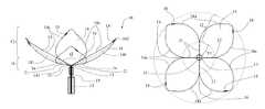
- FIGS. 1A and 1Billustrate a plan view and a top view, respectively, of a distal portion of a retrieval snare in a deployed position, according to one embodiment of the present invention
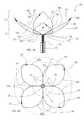
- FIG. 1Cillustrates a plan view of a distal portion of a retrieval snare in a deployed position, according to another embodiment of the present invention
- FIGS. 2A and 2Billustrate a plan and a top view, respectively, of the snare shown in FIGS. 1A and 1B in a partially collapsed position when the snare is partially retracted in a dilator sheath;
- FIGS. 3A and 3Billustrate a side view of the snare shown in FIGS. 2A and 2B during a further retraction in the dilator sheath;
- FIG. 4illustrates a schematic view of connection of the loops of the retrieval snare shown in FIG. 1A to a manipulation member, according to one embodiment of the invention
- FIG. 5illustrates a schematic view of connection of the loops of the retrieval snare shown in FIG. 1A to a manipulation member, according to another embodiment of the invention
- FIG. 6illustrates a side view of a further embodiment of a manipulation member of the retrieval snare of the invention
- FIG. 7illustrates a flowchart diagram that describes the method for manufacturing a retrieval snare, in accordance with one embodiment of this invention.
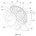
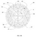
- FIGS. 8A and 8Billustrate a perspective and top view, respectively, of an exemplary weaving jig utilized for preparation of a retrieval snare of the present invention.
- Embodiments of the present inventionprovide a snare that includes a central structure with a plurality of loops at the distal end of the structure.
- the loopsare connected together at joinder length sections located between the distal and proximal ends of the loops to maintain the relative geometry of the loops in both an expanded and compressed condition.
- FIGS. 1A and 1Billustrate plan and top views, respectively, of a distal portion of a retrieval snare 10 in a deployed position for entrapping and retaining a foreign object according to one embodiment of the present invention.
- the structure of the retrieval snare 10has a petal shape and comprises a proximal portion 11 and a distal portion 12 .
- the structureis formed by a plurality of filaments that extend from an end 13 of the proximal portion 11 towards the distal portion 12 and then return to the end 13 to form a plurality of filament loops 14 .
- each side 14 a of each loop 14is directly connected to a side 14 a of an adjacent loop 14 at continues length sections (i.e., at more than one point) between the end 13 and a distal connection point 16 .
- This featureprovides sufficient structural rigidity and dilatation ability to the snare.
- the loops 14are not interconnected in the distal portion 12 . Specifically, the loops 14 deploy radially outward and away from each other in the distal portion 12 when the snare is deployed outside a dilator sheath 15 .
- the dilator sheath 15is a thin-walled, cylindrical flexible tube adapted to penetrate into the body for reaching the foreign object.
- the dilator sheath 15can be made of a plastic material, such as polyvinyl chloride, NYLON, TEFLON, etc.
- the dilator sheath 15can also be made of metal material.
- itcan be made in the form of a coil, (e.g., stainless steel coil) or a metal tube.
- the sheath 15may be multi-layered with different materials in order to provide a graduated bending and stiffness characteristic over its length.
- the filament loops 14are generally flat and planar.
- each side 14 a of the filament loopsis slightly bent or arcuate, as illustrated in FIG. 1A , into an arc (C-shaped configuration).
- Such a configurationcan enhance the ability to slip the loops over the foreign object and grasp it.
- each side 14 a of the filament loopsis slightly undulated, as illustrated in FIG. 1C , into a somewhat S-shaped configuration. Such a configuration can facilitate retraction of the snare into the sheath 15 .
- an opening angle ⁇ of the deployed snareis in the range of about 10 degrees to about 170 degrees.
- the effective value of the opening angledepends on the snare application, and is mainly determined by the size of the foreign object.
- the opening angle ⁇can be defined as an angle between planes of the diametrically opposite loops.
- the opening angle ⁇can be defined as an angle between various parts of segments 141 connecting a distal end 142 , a midpoint 144 , and a proximal end 143 of the loops 14 .
- the proximal end 143 of the loops 14coincides with the end 13 of the proximal portion 11 . It should be understood that when the loops are not planar the segments 141 are also bent. Therefore, the value of the angle ⁇ varies along the loop length. In particular, for the configuration when the loops are bent (see FIG. 1A ), the value of the angle ⁇ is relatively large near the proximal end 143 and small near the distal end 142 . In turn, when the loops are undulated (see FIG. 1C ), the value of the angle ⁇ can be relatively small near the proximal end 143 , comparatively larger near the midpoint 144 of the loop (i.e. where the loop changes slope), and comparatively smaller adjacent the distal end 142 .
- FIGS. 1A-1C and further drawingsan exemplary snare having four filament loops 14 is illustrated in FIGS. 1A-1C and further drawings, the invention is not limited by such a structure. Generally, any desired number of the loops equal to or greater than two may be utilized.
- connection of the sides 14 a of the loops 14 in the proximal portion 11is achieved by twisting each pair of the corresponding sides 14 a by one or more turns and forming twisted parts 21 .
- the filamentsare bound together at the end 13 of the proximal portion 11 .
- the filamentsare bound together by a ferrule 17 crimped or swaged together with the filaments at the end 13 of the proximal portion.
- the filaments that extend from the end 13 outside the proximal portion 11 toward a manipulation member 19are twisted together.
- these twisted filamentscan possess sufficient stiffness in order to form or be a part of the manipulation member 19 of the snare 10 .
- the manipulation member 19is arranged within the dilator sheath 15 and operable for retracting the snare within the sheath 15 and protracting the snare therefrom for its opening.
- the manipulation member 19connects the snare 10 to a manipulator (not shown) that is operable for manipulating the snare for extraction of the foreign object from the body.
- the manipulation member 19is formed from at least a part of the plurality of filaments extending from the end 13 towards the manipulator.
- an operator of the snarecan manipulate the manipulation member 19 by means of the manipulator, and thus the snare 10 can be either retracted within the catheter 15 or protracted therefrom.
- the operatorby holding the manipulator, can also maneuver the catheter 15 within the body organ (not shown), (e.g. to displace it by turning, pushing or pulling).
- a retrieval snare apparatus 40which includes at least one of the snares described above and further includes a manipulation member 41 having a tube 42 containing all or at least a part of the plurality of filaments extending from the end 13 towards a manipulator 44 .
- the filamentscan be twisted together to provide additional rigidity to the manipulation member.
- These filamentsare axially disposed within a lumen of the tube 42 along at least a portion of the tube's length.
- the tube 42 and the filamentscan be bound together.
- the tube and the filamentscan be crimped, swaged, glued, soldered or welded together.
- the tube 42can have one or more notches (not shown) through which a glue or soldering material can be delivered.
- the tube 42may be disposed within the dilator sheath 15 described above (not shown), thereby forming a snare control assembly.
- the tube 42may be arranged between a first ferrule 43 and the manipulator 44 , as shown in FIG. 4 .
- the tube 42can bind together the filaments at the end 13 of the proximal portion 11 , essentially functioning as the first ferrule 43 , and thereby allowing the ferrule 43 to be omitted.
- the tube 42can, for example, be made of a metallic material selected from a NiTi based alloy, or stainless steel.
- the tube 42can be made of a polymer material.
- the manipulation member 41can be connected to the manipulator 44 , for example, through a second ferrule 45 placed and crimped around the tube 42 and the manipulator 44 .
- the manipulation member 41can be directly connected to the manipulator 44 , omitting the ferrule 45 .
- the manipulator 44can be put on the tube 42 and connected by gluing, soldering and/or welding process.
- the manipulator 44can be provided with one or more notches (not shown) through which a glue or soldering material can be delivered.
- FIG. 5a schematic view of connection of the retrieval snare in FIG. 1A to a tube 51 in order to form a manipulation member 50 of the retrieval snare apparatus is shown, according to another embodiment of the present invention.
- the plurality of filaments extended from the end 13are cut off at a predetermined distance from the end, thereby forming free ends 52 of the plurality of filaments. These free ends 52 are placed in a lumen of the tube 51 and are crimped or welded together at position 54 , thereby to form the manipulation member.
- the tube 51 of the manipulation membercan be connected to a manipulator 53 , for example, through a fourth ferrule 55 placed and crimped around the tube and the manipulator 53 .
- the manipulation member 50can be directly connected to the manipulator 53 omitting the ferrule 55 .
- the manipulator 53can be put on the tube 42 and connected by gluing, soldering and/or welding process.
- the manipulator 53can be provided with one or more notches (not shown) through which a glue or soldering material can be delivered to increase the binding surface area.
- FIG. 6shows yet another embodiment of a manipulation member of the retrieval snare of the present invention.
- the plurality of filaments extending from the end 13are cut off at a predetermined distance from the end to form free ends 61 of the plurality of filaments.
- the free ends 61are connected to a rod element 62 .
- the rod element 62is analogous to the manipulation member ( 41 in FIG. 4 ).
- connection of the rod element 62 to the free ends 61 of the filamentscan be implemented through welding or soldering.
- the connection of the rod element 62 to the free ends 61 of the filamentscan be implemented through a fifth ferrule 63 placed and crimped around the rod element 62 and around the free ends.
- the fifth ferrule 63can include a notch 64 configured to facilitate connecting the rod element 62 to the ferrule 63 by at least one connecting technique selected from soldering, welding and gluing.
- the rod element 62can be connected to a manipulator 65 , for example, through a sixth ferrule 66 placed and crimped around the rod element 62 and the manipulator 65 .
- the rod element 62can also be directly connected to the manipulator 65 , for example, by using gluing, soldering or welding process.
- the rod element 62 of the manipulation membercan, for example, be made of a metallic material, such as a NiTi based alloy or stainless steel. Likewise, the rod element 62 can be made of a polymer material.
- each filamentis a single-core wire. According to another embodiment of the invention, each filament is a multi-wire strand.
- the filaments utilized for the fabrication of the retrieval snare 10are made of a suitable material that is suitably biocompatible and has thermo-mechanical shape memory and/or superelastic properties.
- the filamentsare made of a metallic material.
- the metallic materialcan be selected from a group including a NiTi based alloy (e.g., Nitinol), stainless steel and other materials possessing good shape memory, elastic or superelastic characteristics.
- the filamentsare made of non-metallic material, for example Capron, Nylon, etc.
- the filaments of the basketare covered by an insulating layer.
- the insulating layercan, for example, be made of Teflon.
- Teflonis its thermal resistance and low coefficient of mechanical friction, which leads to an additional reduction of traumatism.
- radiopacitymay be provided by the metallic material from which the filaments are made and may include a material which provides radiopacity, for example a noble metal, such as gold, tantalum, platinum, etc.
- the metallic materialcan be alloyed with one or more of the following metals: Pd, W, Nb, Co, Ta, and Cu.
- the filamentsare made of a core tube (cannular strand) containing an axially disposed radiopaque wire, for example, a radiopaque core clad with a different outer material.
- radiopaque materialsinclude Pt, Au, Pd, W, Nb, Co, Ag, Ta, and Cu without limitation.
- cladding materialsinclude stainless steel, Nitinol, and plastics such as Capron and Nylon without limitation.
- the filamentscan have radiopaque parts of a predetermined length. These radiopaque parts can form the distal portion ( 12 in FIG. 1 ) of the snare or at least a part of the distal portion.
- Radiopacitycan also be improved through coating processes such as sputtering or plating a radiopaque material onto the filaments, or the snare fabricated from these filaments, thereby to provide a radiopaque coating layer on the filaments.
- radiopacitycan yet be improved by using radiopaque markers which can be attached to or placed around the filaments forming the snare.
- materials which have higher radiopacity than the snare structure itselfsuch as gold, tantalum or platinum, can be utilized as markers and be strategically placed along the body of the snare to increase the visualization of the snare.
- the retrieval snare 10can comprise one or more radiopaque markers ( 18 in FIG. 1A ) attached to or placed around the filaments forming one or more loops ( 14 in FIG. 1A ) in the distal portion ( 12 in FIG. 1A ).
- the radiopaque markercan be a ferrule put on the filament.
- the filamentscan be multi-wire strands.
- the multi-wire strandscan include a central core wire and at least one another wire twisted about said central core wire which is made of a material having a level of radiopacity greater than the level of radiopacity of said central core wire. Examples of such a material include, but are not limited to, Pt, Au, Pd, Ag, Ta, etc.
- FIGS. 2A and 2Ba plan view and a top view are shown, respectively, of the snare shown in FIGS. 1A and 1B in a partially collapsed position when the snare is partially retracted in a dilator sheath. In this case, the opening angle is decreased.
- the distal connection points 16 of the adjacent loops 14can slide along the filaments' length when the snare 10 is retracted in the dilator sheath 15 .
- the distal connection points 16can move from the twisted parts 21 of the loops 14 toward the distal portion 12 of the snare, thereby forming an intermediate portion 22 between the proximal portion 11 and the distal portion 12 of the snare 10 .
- the intermediate portion 22includes convex cells 23 formed between the distal points 16 and the remaining twisted parts 21 by the corresponding pair 24 of the filaments separated from each other. It should be understood that when the twisting is formed by only one turn (not shown), the convex cells are formed between the end 13 of the proximal portion 11 and the distal connection points 16 .
- FIGS. 3A and 3Bshow the snare shown in FIGS. 2A and 2B during a further retraction in the dilator sheath 15 .
- the proximal portion11 in FIGS. 2A and 2B
- the distal connection points 16move further towards a distal end 31 of the snare of the present invention
- the opening angle ⁇further decreases.
- the processbegins from a step of providing (block 71 ) of a predetermined number of filaments having predetermined properties, predetermined diameter and length.
- the manufacturing of the retrieval snareis carried out from one length of filament.
- the manufacturing of the retrieval snareis carried out from several filaments.
- the number of the filamentsis equal to the number of the filament loops of the snare.
- the filaments selected for the construction of the snarecan be single-core wires, or when desired, can be multi-wire strands.
- the filamentscan have radiopaque parts of a predetermined length.
- the fabrication methodcan include providing radiopaque coils having the predetermined length, which can be put on a core wire in the desired locations along the wire length.
- the coilscan be welded, soldered and/or glued to the wire.
- Other method of binding the coils to the core wirecan also be utilized.
- each coilcan be fixed on the core wire by means of two ferrules put on and crimped together with the core wire at the two ends of the coil.
- the fabrication methodin order to prepare the filaments with radiopaque parts, can include providing radiopaque ferrules and placing the ferrules on a core wire and crimping them in the desired locations along the wire length.
- the process for the fabrication of the retrieval basketincludes weaving the retrieval snare from one length of filament or from several filaments.
- FIGS. 8A and 8Bshow a perspective and top view, respectively, of an exemplary weaving jig 80 suitable for preparation of the retrieval snare of the present invention.
- the jig 80has a structure including grooves arranged in accordance with the desired pattern of the snare of the invention and has a shape that imitates the desired shape of the snare.
- the weaving jig 80has a working surface 81 , where the working surface has a predetermined convex shape defining an opening angle of the snare, and a predetermined pattern formed by radial channels 82 and concentric grooves 85 configured on the surface.
- the working surface 81has a central portion 83 and a peripheral portion 84 .
- the radial channels 82are formed in the form of a plurality of notches extending from a center 86 of the surface towards the peripheral portion 84 .
- the notchesare not interconnected at the peripheral portion 84 of the working surface 81 , but each notch merges with an adjacent notch at a shared common part 87 of the radial channels 82 in the central portion 83 .
- the process for the fabrication of the retrieval snare of the present inventionfurther includes weaving the retrieval snare on the jig 80 .
- the filamentsare placed (block 73 ) into the radial channels 82 to form a plurality of filament loops in accordance with a desired pattern of the snare structure. Free parts of the filaments are arranged in the center 86 of the working surface 81 of the jig 80 .
- the filament loopsare fastened (block 74 ) to the jig at the peripheral portion 84 of the working surface of the jig.
- the filaments forming the loopscan be tied up on the jig 80 , for example, by one or more strings (not shown in FIG. 8 ) wound around the jig in the concentric grooves 85 .
- the stringscan, for example, be made of soft wire having strength sufficient to maintain the fixture of the loops on the jig. Examples of the soft wire include, but are not limited to a copper wire or annealed manganin wire.
- the processincludes the step of connecting (block 75 ) each side of each filament loop disposed in the common part 87 of the radial channels 82 to a side of an adjacent filament loop at more than one point.
- the connection of the sides in the common part of the radial channels 82is achieved by twisting each pair of the filaments forming the corresponding sides along the peripheral portion 84 .
- the number of the connection pointsdetermines structural rigidity of the snare. This number is defined by the number of turns in the twisted portions of the loops.
- free parts of the filaments (not shown) arranged in the center 86 of the working surface and extended therefromare fastened together (block 76 ).
- This fasteningcan, for example, be carried out by a temporal or permanent ferrule (not shown).
- This ferrulecan, for example, be in the form of a pipe made of metal, for example, Ni, stainless steel, etc.
- the ferrulecan be squeezed (crimped) for fixation of the filaments therein. It should be appreciated that this is only a non-limiting example of the filaments' fixation.
- Other techniquescan also be used, for example, soldering, welding or gluing.
- the process of snare fabricationfurther includes annealing (block 77 ) of the retrieval snare for memorizing and storing the snare shape and thereby imparting structural rigidity and dilatation ability to the snare.
- the parameters of the annealingdepend on the materials of the filaments and the method of heating. For example, when such material is Nitinol, the annealing can be carried out at the temperature of about 400° C.-600° C. for about ten min. Such heat treatment relieves internal stresses in the material and provide the memorization of the basket shape. It should be understood that the time for the annealing may be shorter or longer than 10 minutes, depending on the heating technique, jig mass, etc. For example, when the treatment is carried out in a furnace, the treatment time should include the time of heating the jig.
- the heatingis carried out by placing the snare mounted on the weaving jig in a furnace configured for this purpose.
- the heatingis carried out by passing an electric current through the filaments that in this case should be made from at least partially electrically conducting material.
- an electric currentfor example, when the material is Nitinol a current of about one to three amps applied over about two seconds to tens of seconds can be used.
- the snare mounted on the jigis cooled (block 78 ). Then, the parts of the filaments tied at the peripheral portion 84 of the working surface of the jig and, if desired in the center 86 , and then are unfastened (block 79 ); and the jig 80 is removed (block 710 ).
- the free parts of the filaments at the end of the proximal portionare bound permanently together (block 711 ).
- the binding of the free parts of the filaments togethercan, for example, be carried out by a permanent ferrule.
- the retrieval snarewhen the retrieval snare is formed from a single length of filament, in order to place the filament in the radial channels 82 one end of the single length of filament is fixed, while the other end is put on the working surface 81 of the jig 80 and moved along the notches of the radial channels 82 .
- the weaving of the snarecontinues by moving the free end away from the jig and returning it thereto as long as desired to form filament loops. After forming the loops the method repeats all the steps described above.
- the process for fabrication of the retrieval basketcan include a step of forming a manipulation member.
- a certain number of filaments extending from the end of the snare proximal portioncan be cut off, and the remaining wire filaments can be twisted together.
- the twisted wire filamentsare then squeezed and heated for memorizing and storing the twisted form.
- the heatingcan, for example, be performed by applying an electric current across the rod.
- the materialis Nitinol a current of about two to three amps applied over about two to five seconds can be used. It should be understood that the time and current values also depend on the filament diameter and the materials and generally may be shorter than two seconds or longer than five seconds.
- the forming of the manipulation memberincludes the steps of providing the tube 42 , cutting off one or more free parts of the filaments extended from the end 13 , and axially disposing the remaining filaments within a lumen of the tube 42 along at least a portion of the tube's length.
- the remaining filamentscan be twisted together before their disposing within the lumen of the tube 42 .
- the tube and the filamentscan be crimped together.
- other binding techniquescan be used, such as gluing, soldering and/or welding these filaments to the tube.
- the forming of the manipulation memberincludes the steps of providing a tube 51 , cutting off the free parts 52 of the filaments at a predetermined distance from the proximal end 13 of the loops, placing free ends 54 of the filaments obtained after the cutting into a lumen of the tube 51 , and crimping together the pipe 51 and the free ends 54 of the filaments placed in the pipe 51 .
- the forming of the manipulation memberincludes the steps of providing the rod element 61 , providing the ferrule 62 , cutting off all the free parts of the filaments at a predetermined distance from the proximal end 13 of the loops, and connecting the free ends 67 of the filaments obtained after cutting to the rod element 61 through the ferrule 62 that is placed around the rod element 61 and around the ends 67 of the filaments.
- the ferrule 62includes a notch 64 configured for facilitation of the connection of the free ends 67 of the filaments to the rod element 61 by using at least one connecting technique selected from soldering, welding and gluing.
- the method of fabrication of the retrieval snarecan further include providing a dilator sheath ( 15 in FIG. 1A ) adapted to penetrate into the body for reaching the object.
- the method of fabrication of the retrieval snarecan further include the steps of providing the manipulator ( 44 in FIG. 4 ; 53 in FIG. 5 ; 65 in FIG. 6 ) configured for manipulating the snare for extracting the object from the body, arranging the manipulation member ( 41 in FIG. 4 ; 50 in FIG. 5 ) within the dilator sheath, and connecting the manipulation member to the manipulator.
- the connecting of the manipulation member to the manipulatorcan, for example, be carried out by using a ferrule that is placed and crimped around the manipulation member and the manipulator.
- retrieval snares constructed in accordance with the present inventioncan comprise a variety of user desired shapes, number of loops, shape of the loops, types of connection of the loops in the proximal portion and types of connection of the loops to a manipulation member.
- the snare of the present inventionis not limited to a medical treatment of a human body. It can be successfully employed for medical treatments of animals as well. Furthermore, the device of the invention is suitable for retrieval of foreign objects from various cavities in the body systems, for example, from blood vessels, urination tract, etc.
- the present inventionis not limited to fabrication of medical devices, thus the snare device of the invention can be used to extract any type of article from a wide range of inaccessible locations such as inside a pipe or tube (for example, the waste outlet of a domestic sink) or inside a chamber within a large piece of machinery which would be difficult to dismantle.
Landscapes
- Health & Medical Sciences (AREA)
- Surgery (AREA)
- Life Sciences & Earth Sciences (AREA)
- Heart & Thoracic Surgery (AREA)
- Engineering & Computer Science (AREA)
- General Health & Medical Sciences (AREA)
- Molecular Biology (AREA)
- Biomedical Technology (AREA)
- Medical Informatics (AREA)
- Nuclear Medicine, Radiotherapy & Molecular Imaging (AREA)
- Animal Behavior & Ethology (AREA)
- Public Health (AREA)
- Veterinary Medicine (AREA)
- Vascular Medicine (AREA)
- Orthopedic Medicine & Surgery (AREA)
- Oral & Maxillofacial Surgery (AREA)
- Pathology (AREA)
- Mechanical Engineering (AREA)
- Surgical Instruments (AREA)
Abstract
Description
Claims (19)
Priority Applications (2)
| Application Number | Priority Date | Filing Date | Title |
|---|---|---|---|
| US11/866,253US9271746B2 (en) | 2006-10-06 | 2007-10-02 | Retrieval snare for extracting foreign objects from body cavities and method for manufacturing thereof |
| US15/005,163US10201846B2 (en) | 2006-10-06 | 2016-01-25 | Retrieval snare for extracting foreign objects from body cavities and method for manufacturing thereof |
Applications Claiming Priority (2)
| Application Number | Priority Date | Filing Date | Title |
|---|---|---|---|
| US85036906P | 2006-10-06 | 2006-10-06 | |
| US11/866,253US9271746B2 (en) | 2006-10-06 | 2007-10-02 | Retrieval snare for extracting foreign objects from body cavities and method for manufacturing thereof |
Related Child Applications (1)
| Application Number | Title | Priority Date | Filing Date |
|---|---|---|---|
| US15/005,163DivisionUS10201846B2 (en) | 2006-10-06 | 2016-01-25 | Retrieval snare for extracting foreign objects from body cavities and method for manufacturing thereof |
Publications (2)
| Publication Number | Publication Date |
|---|---|
| US20080086149A1 US20080086149A1 (en) | 2008-04-10 |
| US9271746B2true US9271746B2 (en) | 2016-03-01 |
Family
ID=39144363
Family Applications (2)
| Application Number | Title | Priority Date | Filing Date |
|---|---|---|---|
| US11/866,253Active2030-10-02US9271746B2 (en) | 2006-10-06 | 2007-10-02 | Retrieval snare for extracting foreign objects from body cavities and method for manufacturing thereof |
| US15/005,163Active2029-04-29US10201846B2 (en) | 2006-10-06 | 2016-01-25 | Retrieval snare for extracting foreign objects from body cavities and method for manufacturing thereof |
Family Applications After (1)
| Application Number | Title | Priority Date | Filing Date |
|---|---|---|---|
| US15/005,163Active2029-04-29US10201846B2 (en) | 2006-10-06 | 2016-01-25 | Retrieval snare for extracting foreign objects from body cavities and method for manufacturing thereof |
Country Status (4)
| Country | Link |
|---|---|
| US (2) | US9271746B2 (en) |
| EP (1) | EP2068728B1 (en) |
| RU (1) | RU2445025C2 (en) |
| WO (1) | WO2008041094A2 (en) |
Cited By (4)
| Publication number | Priority date | Publication date | Assignee | Title |
|---|---|---|---|---|
| US10258355B2 (en) | 2014-06-12 | 2019-04-16 | Innon Holdings, Llc | Endoscopic stone-extraction device |
| US10448962B2 (en) | 2014-06-12 | 2019-10-22 | Innon Holdings, Llc | Endoscopic stone-extraction device |
| US10925624B2 (en) | 2016-02-29 | 2021-02-23 | Nordson Corporation | Medical device for entrapping and extracting objects from body cavities |
| US11166736B2 (en) | 2013-06-11 | 2021-11-09 | Innon Holdings, Llc | Endoscopic stone-extraction device |
Families Citing this family (43)
| Publication number | Priority date | Publication date | Assignee | Title |
|---|---|---|---|---|
| US10327880B2 (en) | 2000-04-14 | 2019-06-25 | Attenuex Technologies, Inc. | Attenuation device for use in an anatomical structure |
| US6682473B1 (en)* | 2000-04-14 | 2004-01-27 | Solace Therapeutics, Inc. | Devices and methods for attenuation of pressure waves in the body |
| WO2007038476A2 (en)* | 2005-09-26 | 2007-04-05 | Atteneux Technologies, Inc. | Pressure attenuation device |
| US9339367B2 (en)* | 2006-09-11 | 2016-05-17 | Edwards Lifesciences Ag | Embolic deflection device |
| US9480548B2 (en)* | 2006-09-11 | 2016-11-01 | Edwards Lifesciences Ag | Embolic protection device and method of use |
| US9271746B2 (en)* | 2006-10-06 | 2016-03-01 | Cook Medical Technologies Llc | Retrieval snare for extracting foreign objects from body cavities and method for manufacturing thereof |
| DE602008006605D1 (en)* | 2007-12-03 | 2011-06-09 | Medkardia Ltd | STENT PLACEMENT SYSTEM |
| IL188067A (en) | 2007-12-12 | 2011-12-29 | Lithotech Medical Ltd | Device for fragmenting and removing concretions from body ducts and cavities |
| WO2010068467A1 (en)* | 2008-11-25 | 2010-06-17 | Attenuex Technologies, Inc. | Implant with high vapor pressure medium |
| US20120022380A1 (en)* | 2010-01-19 | 2012-01-26 | Chernomorsky Ary S | Methods and apparatus for assesment and treatment of body cavities |
| EP2528517B1 (en) | 2010-01-27 | 2018-04-18 | Merit Medical Systems, Inc. | Shapeable retrieval device |
| EP2552327B1 (en)* | 2010-03-29 | 2017-08-09 | Cook Medical Technologies LLC | Device for positioning an implanted structure to facilitate removal |
| US8974469B2 (en)* | 2010-04-22 | 2015-03-10 | Medical Device Technologies, Inc. | Snare |
| USD654588S1 (en) | 2010-04-22 | 2012-02-21 | Medical Device Technologies, Inc. | Snare |
| EP2661233A4 (en) | 2011-01-04 | 2014-09-03 | Merit Medical Systems Inc | Multiple loop snare |
| US9039713B2 (en) | 2011-05-13 | 2015-05-26 | Merit Medical Systems, Inc. | Releasably attached snare loop retrieval device and method of using the same |
| US8469970B2 (en)* | 2011-07-11 | 2013-06-25 | Great Aspirations Ltd. | Apparatus for entrapping and extracting objects from body cavities |
| US9039715B2 (en) | 2011-07-11 | 2015-05-26 | Great Aspirations Ltd. | Apparatus for entrapping and extracting objects from body cavities |
| US9011350B2 (en) | 2011-11-30 | 2015-04-21 | Lincoln Diagnostics, Inc. | Allergy testing device and method of testing for allergies |
| US10548706B2 (en) | 2012-01-13 | 2020-02-04 | Volcano Corporation | Retrieval snare device and method |
| US10426501B2 (en) | 2012-01-13 | 2019-10-01 | Crux Biomedical, Inc. | Retrieval snare device and method |
| US10213288B2 (en) | 2012-03-06 | 2019-02-26 | Crux Biomedical, Inc. | Distal protection filter |
| US8894563B2 (en) | 2012-08-10 | 2014-11-25 | Attenuex Technologies, Inc. | Methods and systems for performing a medical procedure |
| EP2967604A4 (en)* | 2013-03-15 | 2016-11-23 | Volcano Corp | Retrieval and centering device and method with pressure and ultrasound features |
| US10350098B2 (en) | 2013-12-20 | 2019-07-16 | Volcano Corporation | Devices and methods for controlled endoluminal filter deployment |
| RU2695535C2 (en) | 2013-12-30 | 2019-07-23 | Меди-Тейт Лтд. | Perforating implant for urethra |
| WO2015103189A1 (en) | 2014-01-03 | 2015-07-09 | Boston Scientific Scimed, Inc. | Retrieval devices |
| DE102014207344A1 (en)* | 2014-04-16 | 2015-10-22 | Epflex Feinwerktechnik Gmbh | Safety wire instrument with distal catch structure |
| US10524810B2 (en) | 2015-03-04 | 2020-01-07 | Gyrus Acmi, Inc. | Medical device for capturing stone fragments |
| US20160262844A1 (en)* | 2015-03-09 | 2016-09-15 | Nexus Control Systems Llc | Method and system for detecting and marking metallic materials on and inside the human body |
| CN105496600B (en)* | 2015-12-31 | 2020-09-29 | 先健科技(深圳)有限公司 | Catching device |
| CA2957130C (en)* | 2016-02-12 | 2021-01-26 | Covidien Lp | Vascular device marker attachment |
| US10052185B2 (en) | 2016-02-12 | 2018-08-21 | Covidien Lp | Vascular device marker attachment |
| US10265089B2 (en) | 2016-02-12 | 2019-04-23 | Covidien Lp | Vascular device visibility |
| RU2664959C2 (en)* | 2016-11-30 | 2018-08-23 | Федеральное государственное бюджетное образовательное учреждение высшего образования "Сибирский государственный медицинский университет" Министерства здравоохранения Российской Федерации (ФГБОУ ВО СибГМУ Минздрава России) | Method and device for endoscopic lithotripsy of concrements in bile ducts |
| USD903116S1 (en)* | 2018-03-12 | 2020-11-24 | Olympus Corporation | Surgical snare |
| WO2020139979A1 (en)* | 2018-12-27 | 2020-07-02 | C. R. Bard, Inc. | Extraction basket |
| WO2020163625A1 (en) | 2019-02-07 | 2020-08-13 | Solace Therapeutics, Inc. | Pressure attenuation device |
| EP3795090A1 (en)* | 2019-09-23 | 2021-03-24 | Institut Químic de Sarrià CETS Fundació Privada | Patch deployment device |
| CN110507447A (en)* | 2019-09-24 | 2019-11-29 | 浙江归创医疗器械有限公司 | Vena cava filter and its recyclable device |
| IT202000012625A1 (en)* | 2020-05-27 | 2021-11-27 | Innovheart S R L | Device for grasping guide wires |
| RU210500U1 (en)* | 2021-11-29 | 2022-04-18 | Артем Тимурбекович Салсанов | thromboextractor |
| CN118576275A (en)* | 2024-06-24 | 2024-09-03 | 广东远帆医疗科技有限公司 | Capture device and method of manufacturing the same |
Citations (59)
| Publication number | Priority date | Publication date | Assignee | Title |
|---|---|---|---|---|
| US3828790A (en) | 1973-02-28 | 1974-08-13 | American Cystoscope Makers Inc | Surgical snare |
| US3955578A (en) | 1974-12-23 | 1976-05-11 | Cook Inc. | Rotatable surgical snare |
| US5098440A (en) | 1990-08-14 | 1992-03-24 | Cordis Corporation | Object retrieval method and apparatus |
| US5098441A (en) | 1989-04-05 | 1992-03-24 | Dr. Andreas Lindner Unternehmensberatung | Lithotriptor |
| US5133733A (en) | 1989-11-28 | 1992-07-28 | William Cook Europe A/S | Collapsible filter for introduction in a blood vessel of a patient |
| US5171233A (en)* | 1990-04-25 | 1992-12-15 | Microvena Corporation | Snare-type probe |
| US5171314A (en) | 1990-07-24 | 1992-12-15 | Andrew Surgical, Inc. | Surgical snare |
| US5201741A (en) | 1990-07-24 | 1993-04-13 | Andrew Surgical, Inc. | Surgical snare with shape memory effect wire |
| US5387219A (en) | 1992-09-23 | 1995-02-07 | Target Therapeutics | Medical retrieval snare with coil wrapped loop |
| US5522819A (en) | 1994-05-12 | 1996-06-04 | Target Therapeutics, Inc. | Dual coil medical retrieval device |
| US5603694A (en)* | 1995-10-17 | 1997-02-18 | Brown; Joe E. | Infusion coil apparatus and method for delivering fluid-based agents intravascularly |
| US5724989A (en) | 1995-06-20 | 1998-03-10 | The Microspring Company, Inc. | Radiopaque medical devices |
| US5906622A (en) | 1997-04-29 | 1999-05-25 | Lippitt; Robert G. | Positively expanded and retracted medical extractor |
| US5910129A (en) | 1996-12-19 | 1999-06-08 | Ep Technologies, Inc. | Catheter distal assembly with pull wires |
| US5924175A (en) | 1997-04-29 | 1999-07-20 | Lippitt; Robert G. | Annularly expanding and retracting gripping and releasing mechanism |
| US6066149A (en) | 1997-09-30 | 2000-05-23 | Target Therapeutics, Inc. | Mechanical clot treatment device with distal filter |
| US6086577A (en) | 1997-08-13 | 2000-07-11 | Scimed Life Systems, Inc. | Detachable aneurysm neck bridge (III) |
| US6096034A (en) | 1996-07-26 | 2000-08-01 | Target Therapeutics, Inc. | Aneurysm closure device assembly |
| US6099534A (en) | 1997-10-01 | 2000-08-08 | Scimed Life Systems, Inc. | Releasable basket |
| WO2000071036A2 (en)* | 1999-05-25 | 2000-11-30 | Scimed Life Systems, Inc. | Releasable basket and method of making thereof |
| US6179861B1 (en) | 1999-07-30 | 2001-01-30 | Incept Llc | Vascular device having one or more articulation regions and methods of use |
| US6187017B1 (en) | 1998-02-17 | 2001-02-13 | Circon Corporation | Retrieval basket for a surgical device |
| US6191365B1 (en) | 1997-05-02 | 2001-02-20 | General Science And Technology Corp | Medical devices incorporating at least one element made from a plurality of twisted and drawn wires |
| US6193708B1 (en) | 1997-08-05 | 2001-02-27 | Scimed Life Systems, Inc. | Detachable aneurysm neck bridge (I) |
| US6214025B1 (en)* | 1994-11-30 | 2001-04-10 | Boston Scientific Corporation | Self-centering, self-expanding and retrievable vena cava filter |
| US6217589B1 (en) | 1999-10-27 | 2001-04-17 | Scimed Life Systems, Inc. | Retrieval device made of precursor alloy cable and method of manufacturing |
| US6235026B1 (en) | 1999-08-06 | 2001-05-22 | Scimed Life Systems, Inc. | Polypectomy snare instrument |
| US6245078B1 (en) | 1999-04-26 | 2001-06-12 | Asahi Kogaku Kogyo Kabushiki Kaisha | Snare for endoscope |
| US6278057B1 (en) | 1997-05-02 | 2001-08-21 | General Science And Technology Corp. | Medical devices incorporating at least one element made from a plurality of twisted and drawn wires at least one of the wires being a nickel-titanium alloy wire |
| US20010049535A1 (en)* | 1998-04-23 | 2001-12-06 | Leveillee Raymond J. | Medical retrieval device with loop basket |
| US6352539B1 (en) | 1997-05-02 | 2002-03-05 | Scilogy Corp. | Surgical instrument with rotatable shaft |
| US6361540B1 (en) | 2000-04-06 | 2002-03-26 | Michael W. L. Gauderer | Apparatus for removal of esophageal coins and similarly shaped objects |
| US6375661B2 (en) | 1995-04-13 | 2002-04-23 | Boston Scientific Corporation | Apparatus for severing and capturing polyps |
| US6402771B1 (en) | 1999-12-23 | 2002-06-11 | Guidant Endovascular Solutions | Snare |
| US20020133170A1 (en) | 2001-03-13 | 2002-09-19 | Olympus Optical Co., Ltd. | Medical retrieval instrument |
| US6458145B1 (en) | 2000-11-28 | 2002-10-01 | Hatch Medical L.L.C. | Intra vascular snare and method of forming the same |
| US6458139B1 (en) | 1999-06-21 | 2002-10-01 | Endovascular Technologies, Inc. | Filter/emboli extractor for use in variable sized blood vessels |
| EP1273268A1 (en) | 2001-07-02 | 2003-01-08 | Terumo Kabushiki Kaisha | Intravascular obstruction removing wire |
| US6554842B2 (en) | 2000-03-10 | 2003-04-29 | Radius Medical Technologies, Inc. | Small diameter snare |
| US20030130685A1 (en) | 1997-03-06 | 2003-07-10 | Scimed Life Systems, Inc. | Distal protection device and method |
| US20030135222A1 (en) | 2000-02-17 | 2003-07-17 | Kanag Baska | Surgical snare |
| US20030167052A1 (en) | 1999-12-29 | 2003-09-04 | Lee Jeong S. | Catheter assemblies with flexible radiopaque marker |
| US6616617B1 (en) | 1997-12-05 | 2003-09-09 | Micrus Corporation | Vasoocclusive device for treatment of aneurysms |
| US20040049226A1 (en) | 1997-11-07 | 2004-03-11 | Martin Keegan | Embolic protection system |
| WO2004056275A1 (en) | 2002-12-23 | 2004-07-08 | Lithotech Medical Ltd. | Surgical device for extracting a foreign object and method for manufacturing thereof |
| US20040138693A1 (en) | 2003-01-14 | 2004-07-15 | Scimed Life Systems, Inc. | Snare retrievable embolic protection filter with guidewire stopper |
| US20040220608A1 (en) | 2003-05-01 | 2004-11-04 | D'aquanni Peter | Radiopaque nitinol embolic protection frame |
| US20040243174A1 (en) | 2000-11-03 | 2004-12-02 | Ackerman Andrew J. | Medical grasping device having embolic protection |
| US20050021074A1 (en) | 2003-07-24 | 2005-01-27 | Elliott Christopher J. | Embolic coil |
| US20050033348A1 (en)* | 2000-06-29 | 2005-02-10 | Concentric Medical, Inc. | Systems, methods and devices for removing obstructions from a blood vessel |
| US20050049612A1 (en) | 2000-11-03 | 2005-03-03 | Jason Urbanski | Medical grasping device |
| US20050055045A1 (en) | 2003-09-10 | 2005-03-10 | Scimed Life Systems, Inc. | Composite medical devices |
| US20050113845A1 (en) | 2003-11-20 | 2005-05-26 | Scimed Life Systems, Inc. | Self-orienting polypectomy snare device |
| US20050125024A1 (en) | 2000-06-29 | 2005-06-09 | Concentric Medical, Inc., A Delaware Corporation | Systems, methods and devices for removing obstructions from a blood vessel |
| US20050209634A1 (en) | 1999-05-07 | 2005-09-22 | Salviac Limited | Support frame for an embolic protection device |
| US20050234474A1 (en) | 2004-03-08 | 2005-10-20 | Demello Richard M | Small-diameter snare |
| US20060009785A1 (en) | 2003-11-13 | 2006-01-12 | The Regents Of The University Of California | Shape memory polymer medical device |
| US7011681B2 (en) | 1997-12-29 | 2006-03-14 | The Cleveland Clinic Foundation | Bioprosthetic cardiovascular valve system |
| EP1695673A2 (en) | 1994-07-08 | 2006-08-30 | ev3 Inc. | Intravascular filtering device |
Family Cites Families (5)
| Publication number | Priority date | Publication date | Assignee | Title |
|---|---|---|---|---|
| SU1648406A1 (en)* | 1989-02-27 | 1991-05-15 | Винницкая областная клиническая больница им.Н.И.Пирогова | Extractor for removing calculi from body cavities |
| JPH03241598A (en)* | 1990-02-19 | 1991-10-28 | Fujitsu Ltd | signature circuit |
| ATE372729T1 (en)* | 2001-06-28 | 2007-09-15 | Lithotech Medical Ltd | DEVICE FOR CATCHING FOREIGN BODY |
| US9271746B2 (en)* | 2006-10-06 | 2016-03-01 | Cook Medical Technologies Llc | Retrieval snare for extracting foreign objects from body cavities and method for manufacturing thereof |
| US9039715B2 (en)* | 2011-07-11 | 2015-05-26 | Great Aspirations Ltd. | Apparatus for entrapping and extracting objects from body cavities |
- 2007
- 2007-10-02USUS11/866,253patent/US9271746B2/enactiveActive
- 2007-10-02EPEP07825240.0Apatent/EP2068728B1/enactiveActive
- 2007-10-02RURU2009115703/14Apatent/RU2445025C2/enactive
- 2007-10-02WOPCT/IB2007/002895patent/WO2008041094A2/enactiveApplication Filing
- 2016
- 2016-01-25USUS15/005,163patent/US10201846B2/enactiveActive
Patent Citations (70)
| Publication number | Priority date | Publication date | Assignee | Title |
|---|---|---|---|---|
| US3828790A (en) | 1973-02-28 | 1974-08-13 | American Cystoscope Makers Inc | Surgical snare |
| US3955578A (en) | 1974-12-23 | 1976-05-11 | Cook Inc. | Rotatable surgical snare |
| US5098441A (en) | 1989-04-05 | 1992-03-24 | Dr. Andreas Lindner Unternehmensberatung | Lithotriptor |
| US5133733A (en) | 1989-11-28 | 1992-07-28 | William Cook Europe A/S | Collapsible filter for introduction in a blood vessel of a patient |
| US5171233A (en)* | 1990-04-25 | 1992-12-15 | Microvena Corporation | Snare-type probe |
| US5171314A (en) | 1990-07-24 | 1992-12-15 | Andrew Surgical, Inc. | Surgical snare |
| US5201741A (en) | 1990-07-24 | 1993-04-13 | Andrew Surgical, Inc. | Surgical snare with shape memory effect wire |
| US5098440A (en) | 1990-08-14 | 1992-03-24 | Cordis Corporation | Object retrieval method and apparatus |
| US5387219A (en) | 1992-09-23 | 1995-02-07 | Target Therapeutics | Medical retrieval snare with coil wrapped loop |
| US5522819A (en) | 1994-05-12 | 1996-06-04 | Target Therapeutics, Inc. | Dual coil medical retrieval device |
| EP1695673A2 (en) | 1994-07-08 | 2006-08-30 | ev3 Inc. | Intravascular filtering device |
| US6214025B1 (en)* | 1994-11-30 | 2001-04-10 | Boston Scientific Corporation | Self-centering, self-expanding and retrievable vena cava filter |
| US6375661B2 (en) | 1995-04-13 | 2002-04-23 | Boston Scientific Corporation | Apparatus for severing and capturing polyps |
| US5724989A (en) | 1995-06-20 | 1998-03-10 | The Microspring Company, Inc. | Radiopaque medical devices |
| US5603694A (en)* | 1995-10-17 | 1997-02-18 | Brown; Joe E. | Infusion coil apparatus and method for delivering fluid-based agents intravascularly |
| US6096034A (en) | 1996-07-26 | 2000-08-01 | Target Therapeutics, Inc. | Aneurysm closure device assembly |
| US5910129A (en) | 1996-12-19 | 1999-06-08 | Ep Technologies, Inc. | Catheter distal assembly with pull wires |
| US20030130685A1 (en) | 1997-03-06 | 2003-07-10 | Scimed Life Systems, Inc. | Distal protection device and method |
| US5924175A (en) | 1997-04-29 | 1999-07-20 | Lippitt; Robert G. | Annularly expanding and retracting gripping and releasing mechanism |
| US5906622A (en) | 1997-04-29 | 1999-05-25 | Lippitt; Robert G. | Positively expanded and retracted medical extractor |
| US6352539B1 (en) | 1997-05-02 | 2002-03-05 | Scilogy Corp. | Surgical instrument with rotatable shaft |
| US6278057B1 (en) | 1997-05-02 | 2001-08-21 | General Science And Technology Corp. | Medical devices incorporating at least one element made from a plurality of twisted and drawn wires at least one of the wires being a nickel-titanium alloy wire |
| US6191365B1 (en) | 1997-05-02 | 2001-02-20 | General Science And Technology Corp | Medical devices incorporating at least one element made from a plurality of twisted and drawn wires |
| US6193708B1 (en) | 1997-08-05 | 2001-02-27 | Scimed Life Systems, Inc. | Detachable aneurysm neck bridge (I) |
| US6086577A (en) | 1997-08-13 | 2000-07-11 | Scimed Life Systems, Inc. | Detachable aneurysm neck bridge (III) |
| US6066149A (en) | 1997-09-30 | 2000-05-23 | Target Therapeutics, Inc. | Mechanical clot treatment device with distal filter |
| US20020026203A1 (en)* | 1997-10-01 | 2002-02-28 | Bates James S. | Releasable basket |
| US20060009786A1 (en) | 1997-10-01 | 2006-01-12 | Boston Scientific Scimed, Inc. | Releasable basket |
| US6942673B2 (en) | 1997-10-01 | 2005-09-13 | Boston Scientific Scimed, Inc. | Releasable basket |
| US6520968B2 (en) | 1997-10-01 | 2003-02-18 | Scimed Life Systems | Releasable basket |
| US6280451B1 (en) | 1997-10-01 | 2001-08-28 | Scimed Life Systems, Inc. | Releasable basket |
| US6099534A (en) | 1997-10-01 | 2000-08-08 | Scimed Life Systems, Inc. | Releasable basket |
| US20040049226A1 (en) | 1997-11-07 | 2004-03-11 | Martin Keegan | Embolic protection system |
| US6616617B1 (en) | 1997-12-05 | 2003-09-09 | Micrus Corporation | Vasoocclusive device for treatment of aneurysms |
| US7011681B2 (en) | 1997-12-29 | 2006-03-14 | The Cleveland Clinic Foundation | Bioprosthetic cardiovascular valve system |
| US6187017B1 (en) | 1998-02-17 | 2001-02-13 | Circon Corporation | Retrieval basket for a surgical device |
| US20010049535A1 (en)* | 1998-04-23 | 2001-12-06 | Leveillee Raymond J. | Medical retrieval device with loop basket |
| US6626915B2 (en) | 1998-04-23 | 2003-09-30 | Scimed Life Systems, Inc. | Medical retrieval device with loop basket |
| US6245078B1 (en) | 1999-04-26 | 2001-06-12 | Asahi Kogaku Kogyo Kabushiki Kaisha | Snare for endoscope |
| US20050209634A1 (en) | 1999-05-07 | 2005-09-22 | Salviac Limited | Support frame for an embolic protection device |
| WO2000071036A2 (en)* | 1999-05-25 | 2000-11-30 | Scimed Life Systems, Inc. | Releasable basket and method of making thereof |
| WO2000071036A3 (en)* | 1999-05-25 | 2001-06-28 | Scimed Life Systems Inc | Releasable basket and method of making thereof |
| US6458139B1 (en) | 1999-06-21 | 2002-10-01 | Endovascular Technologies, Inc. | Filter/emboli extractor for use in variable sized blood vessels |
| US6179861B1 (en) | 1999-07-30 | 2001-01-30 | Incept Llc | Vascular device having one or more articulation regions and methods of use |
| US6235026B1 (en) | 1999-08-06 | 2001-05-22 | Scimed Life Systems, Inc. | Polypectomy snare instrument |
| US6217589B1 (en) | 1999-10-27 | 2001-04-17 | Scimed Life Systems, Inc. | Retrieval device made of precursor alloy cable and method of manufacturing |
| US20040068271A1 (en) | 1999-10-27 | 2004-04-08 | Scimed Life Systems, Inc. | Retrieval device made of precursor alloy cable |
| US6402771B1 (en) | 1999-12-23 | 2002-06-11 | Guidant Endovascular Solutions | Snare |
| US6913612B2 (en) | 1999-12-23 | 2005-07-05 | Endovascular Technologies, Inc. | Snare |
| US20050222607A1 (en) | 1999-12-23 | 2005-10-06 | Olin Palmer | Snare |
| US20030167052A1 (en) | 1999-12-29 | 2003-09-04 | Lee Jeong S. | Catheter assemblies with flexible radiopaque marker |
| US20030135222A1 (en) | 2000-02-17 | 2003-07-17 | Kanag Baska | Surgical snare |
| US6554842B2 (en) | 2000-03-10 | 2003-04-29 | Radius Medical Technologies, Inc. | Small diameter snare |
| US6361540B1 (en) | 2000-04-06 | 2002-03-26 | Michael W. L. Gauderer | Apparatus for removal of esophageal coins and similarly shaped objects |
| US20050125024A1 (en) | 2000-06-29 | 2005-06-09 | Concentric Medical, Inc., A Delaware Corporation | Systems, methods and devices for removing obstructions from a blood vessel |
| US20050033348A1 (en)* | 2000-06-29 | 2005-02-10 | Concentric Medical, Inc. | Systems, methods and devices for removing obstructions from a blood vessel |
| US20040243174A1 (en) | 2000-11-03 | 2004-12-02 | Ackerman Andrew J. | Medical grasping device having embolic protection |
| US20050049612A1 (en) | 2000-11-03 | 2005-03-03 | Jason Urbanski | Medical grasping device |
| US6458145B1 (en) | 2000-11-28 | 2002-10-01 | Hatch Medical L.L.C. | Intra vascular snare and method of forming the same |
| US20020133170A1 (en) | 2001-03-13 | 2002-09-19 | Olympus Optical Co., Ltd. | Medical retrieval instrument |
| US20030018355A1 (en) | 2001-07-02 | 2003-01-23 | Katsuya Goto | Intravascular obstruction removing wire and medical instrument |
| EP1273268A1 (en) | 2001-07-02 | 2003-01-08 | Terumo Kabushiki Kaisha | Intravascular obstruction removing wire |
| WO2004056275A1 (en) | 2002-12-23 | 2004-07-08 | Lithotech Medical Ltd. | Surgical device for extracting a foreign object and method for manufacturing thereof |
| US20040138693A1 (en) | 2003-01-14 | 2004-07-15 | Scimed Life Systems, Inc. | Snare retrievable embolic protection filter with guidewire stopper |
| US20040220608A1 (en) | 2003-05-01 | 2004-11-04 | D'aquanni Peter | Radiopaque nitinol embolic protection frame |
| US20050021074A1 (en) | 2003-07-24 | 2005-01-27 | Elliott Christopher J. | Embolic coil |
| US20050055045A1 (en) | 2003-09-10 | 2005-03-10 | Scimed Life Systems, Inc. | Composite medical devices |
| US20060009785A1 (en) | 2003-11-13 | 2006-01-12 | The Regents Of The University Of California | Shape memory polymer medical device |
| US20050113845A1 (en) | 2003-11-20 | 2005-05-26 | Scimed Life Systems, Inc. | Self-orienting polypectomy snare device |
| US20050234474A1 (en) | 2004-03-08 | 2005-10-20 | Demello Richard M | Small-diameter snare |
Non-Patent Citations (1)
| Title |
|---|
| International Search Report-PCT/1B2007/002895 (Apr. 9, 2008). |
Cited By (4)
| Publication number | Priority date | Publication date | Assignee | Title |
|---|---|---|---|---|
| US11166736B2 (en) | 2013-06-11 | 2021-11-09 | Innon Holdings, Llc | Endoscopic stone-extraction device |
| US10258355B2 (en) | 2014-06-12 | 2019-04-16 | Innon Holdings, Llc | Endoscopic stone-extraction device |
| US10448962B2 (en) | 2014-06-12 | 2019-10-22 | Innon Holdings, Llc | Endoscopic stone-extraction device |
| US10925624B2 (en) | 2016-02-29 | 2021-02-23 | Nordson Corporation | Medical device for entrapping and extracting objects from body cavities |
Also Published As
| Publication number | Publication date |
|---|---|
| EP2068728B1 (en) | 2013-11-20 |
| US10201846B2 (en) | 2019-02-12 |
| US20080086149A1 (en) | 2008-04-10 |
| WO2008041094A2 (en) | 2008-04-10 |
| RU2445025C2 (en) | 2012-03-20 |
| WO2008041094A3 (en) | 2008-05-29 |
| RU2009115703A (en) | 2010-11-20 |
| EP2068728A2 (en) | 2009-06-17 |
| US20160136720A1 (en) | 2016-05-19 |
Similar Documents
| Publication | Publication Date | Title |
|---|---|---|
| US10201846B2 (en) | Retrieval snare for extracting foreign objects from body cavities and method for manufacturing thereof | |
| US8469970B2 (en) | Apparatus for entrapping and extracting objects from body cavities | |
| US9039715B2 (en) | Apparatus for entrapping and extracting objects from body cavities | |
| US5792145A (en) | Surgical retrieval baskets | |
| EP1404237B1 (en) | Foreign body retrieval device | |
| JP4732665B2 (en) | Hybrid stone recovery device | |
| EP1583477B1 (en) | Surgical device for extracting a foreign object and method for manufacturing thereof | |
| EP0590050B1 (en) | Endoscopic extraction device having composite wire construction | |
| EP1656072B1 (en) | Ureteral backstop filter and retrieval device | |
| US20060004404A1 (en) | Method for manufacturing a surgical device for extracting a foreign object | |
| JPH08509411A (en) | Dual coil medical recovery device | |
| EP3210552A1 (en) | Medical device for entrapping and extracting objects from body cavities | |
| CA2205433C (en) | Surgical retrieval baskets and method for making the same |
Legal Events
| Date | Code | Title | Description |
|---|---|---|---|
| AS | Assignment | Owner name:LITHOTECH MEDICAL LTD., ISRAEL Free format text:ASSIGNMENT OF ASSIGNORS INTEREST;ASSIGNORS:DELANEY, KEVIN L.;DIAMANT, VALERY;YASKO, NADEZDA;REEL/FRAME:020346/0215;SIGNING DATES FROM 20071011 TO 20071113 Owner name:COOK INCORPORATED, INDIANA Free format text:ASSIGNMENT OF ASSIGNORS INTEREST;ASSIGNORS:DELANEY, KEVIN L.;DIAMANT, VALERY;YASKO, NADEZDA;REEL/FRAME:020346/0215;SIGNING DATES FROM 20071011 TO 20071113 Owner name:LITHOTECH MEDICAL LTD., ISRAEL Free format text:ASSIGNMENT OF ASSIGNORS INTEREST;ASSIGNORS:DELANEY, KEVIN L.;DIAMANT, VALERY;YASKO, NADEZDA;SIGNING DATES FROM 20071011 TO 20071113;REEL/FRAME:020346/0215 Owner name:COOK INCORPORATED, INDIANA Free format text:ASSIGNMENT OF ASSIGNORS INTEREST;ASSIGNORS:DELANEY, KEVIN L.;DIAMANT, VALERY;YASKO, NADEZDA;SIGNING DATES FROM 20071011 TO 20071113;REEL/FRAME:020346/0215 | |
| AS | Assignment | Owner name:COOK MEDICAL TECHNOLOGIES LLC, INDIANA Free format text:ASSIGNMENT OF ASSIGNORS INTEREST;ASSIGNOR:COOK INCORPORATED;REEL/FRAME:037535/0229 Effective date:20160113 | |
| STCF | Information on status: patent grant | Free format text:PATENTED CASE | |
| AS | Assignment | Owner name:NORDSON CORPORATION, OHIO Free format text:ASSIGNMENT OF ASSIGNORS INTEREST;ASSIGNOR:LITHOTECH MEDICAL LTD.;REEL/FRAME:044029/0714 Effective date:20171102 | |
| MAFP | Maintenance fee payment | Free format text:PAYMENT OF MAINTENANCE FEE, 4TH YEAR, LARGE ENTITY (ORIGINAL EVENT CODE: M1551); ENTITY STATUS OF PATENT OWNER: LARGE ENTITY Year of fee payment:4 | |
| MAFP | Maintenance fee payment | Free format text:PAYMENT OF MAINTENANCE FEE, 8TH YEAR, LARGE ENTITY (ORIGINAL EVENT CODE: M1552); ENTITY STATUS OF PATENT OWNER: LARGE ENTITY Year of fee payment:8 | |
| AS | Assignment | Owner name:WILMINGTON TRUST, NATIONAL ASSOCIATION, AS COLLATERAL AGENT, DELAWARE Free format text:SECURITY INTEREST;ASSIGNOR:COOK MEDICAL TECHNOLOGIES LLC;REEL/FRAME:066700/0277 Effective date:20240227 |