US9271592B2 - Adjustable tension-mounted curved rod assembly - Google Patents
Adjustable tension-mounted curved rod assemblyDownload PDFInfo
- Publication number
- US9271592B2 US9271592B2US13/676,800US201213676800AUS9271592B2US 9271592 B2US9271592 B2US 9271592B2US 201213676800 AUS201213676800 AUS 201213676800AUS 9271592 B2US9271592 B2US 9271592B2
- Authority
- US
- United States
- Prior art keywords
- tube
- rod assembly
- secured
- adjustable rod
- support
- Prior art date
- Legal status (The legal status is an assumption and is not a legal conclusion. Google has not performed a legal analysis and makes no representation as to the accuracy of the status listed.)
- Active, expires
Links
Images


Classifications
- A—HUMAN NECESSITIES
- A47—FURNITURE; DOMESTIC ARTICLES OR APPLIANCES; COFFEE MILLS; SPICE MILLS; SUCTION CLEANERS IN GENERAL
- A47H—FURNISHINGS FOR WINDOWS OR DOORS
- A47H1/00—Curtain suspension devices
- A47H1/02—Curtain rods
- A47H1/022—Curtain rods extensible
- A—HUMAN NECESSITIES
- A47—FURNITURE; DOMESTIC ARTICLES OR APPLIANCES; COFFEE MILLS; SPICE MILLS; SUCTION CLEANERS IN GENERAL
- A47H—FURNISHINGS FOR WINDOWS OR DOORS
- A47H1/00—Curtain suspension devices
- A47H1/10—Means for mounting curtain rods or rails
- A47H1/14—Brackets for supporting rods or rails
- A47H1/142—Brackets for supporting rods or rails for supporting rods
- A—HUMAN NECESSITIES
- A47—FURNITURE; DOMESTIC ARTICLES OR APPLIANCES; COFFEE MILLS; SPICE MILLS; SUCTION CLEANERS IN GENERAL
- A47H—FURNISHINGS FOR WINDOWS OR DOORS
- A47H1/00—Curtain suspension devices
- A47H1/02—Curtain rods
- A47H2001/0205—Curtain rods being curved
- A—HUMAN NECESSITIES
- A47—FURNITURE; DOMESTIC ARTICLES OR APPLIANCES; COFFEE MILLS; SPICE MILLS; SUCTION CLEANERS IN GENERAL
- A47H—FURNISHINGS FOR WINDOWS OR DOORS
- A47H1/00—Curtain suspension devices
- A47H1/02—Curtain rods
- A47H2001/0215—Curtain rods being tubular
- A—HUMAN NECESSITIES
- A47—FURNITURE; DOMESTIC ARTICLES OR APPLIANCES; COFFEE MILLS; SPICE MILLS; SUCTION CLEANERS IN GENERAL
- A47K—SANITARY EQUIPMENT NOT OTHERWISE PROVIDED FOR; TOILET ACCESSORIES
- A47K3/00—Baths; Douches; Appurtenances therefor
- A47K3/28—Showers or bathing douches
- A47K3/38—Curtain arrangements
Definitions
- An embodiment of the present inventionrelates generally to an adjustable tension rod, and more particularly, to an adjustable tension-mounted curved shower curtain rod assembly.
- Adjustable length tension rods for use as curtain or shower curtain rodsare generally known. These tension rods typically include a single straight rod having a first straight shaft that telescopingly receives a second straight shaft, wherein the first and second shafts house a long threaded stud. Curved shower curtain rods, however, typically require the use of screws, bolts, and the like in order to permanently fix the curved rod to support surfaces through. This results in curved shower curtain rods being more complex to install and the risk of permanently damaging the support surfaces upon removal of the curved rod.
- one embodiment of the present inventionis directed to an adjustable rod assembly comprising a first tube having a first arcuate portion, a second tube having a second arcuate portion, a third tube of a generally straight configuration, a fourth tube of a generally straight configuration, a first end support, a second end support, and a tension rod mechanism fixedly secured within the third tube for rotational movement therewith.
- a first end of the first tubeis telescopingly received within the third tube and a second end of the first tube is telescopingly received within the second tube.
- the third tubeis rotatable relative to the first tube and is rotatably secured within the fourth tube.
- the fourth tubeis secured to the first end support and the second tube is secured to the second end support.
- the tension rod mechanismhas a threaded portion configured to extend from an interior of the third tube to an interior of the first tube.
- Another embodiment of the present inventionis directed to a method of installing an adjustable rod assembly.
- the steps of the methodcomprise providing an assembled adjustable rod assembly by: (i) providing a first tube having an arcuate portion and first and second opposing ends, a second tube having an arcuate portion and first and second opposing ends, a third tube having first and second opposing ends, a first end support and a second end support; (ii) telescopingly inserting the second end of the first tube in the first end of the second tube and telescopingly inserting the first end of the first tube in the second end of the third tube; and (iii) pivotably securing the second end of the second tube to the second end support and rotatably securing the third tube to the first end support.
- the stepsfurther comprise: b) positioning the assembled adjustable rod assembly between two opposing support surfaces, c) adjusting a length of the assembled adjustable rod assembly such that a respective rear surface of each of the first and second end supports is proximate a respective one of the opposing support surfaces, and d) rotating the third tube about a longitudinal axis thereof until the respective rear surface of each of the first and second end supports directly contacts a respective one of the opposing support surfaces and the assembled adjustable rod assembly applies a compressive force against the opposing support surfaces.
- the present inventionis directed to an adjustable rod assembly comprising a first tube having a first end, a second end and a first arcuate portion; a second tube having a first end, a second end and a second arcuate portion; a third tube of a generally straight configuration having a first end and a second end; a fourth tube of a generally straight configuration having a first end and a second end; first and second end supports; and a tension mechanism including a rod with a connector and a threaded portion.
- the second end of the first tubeis telescopingly received within the first end of the second tube.
- the first end of the first tubeis telescopingly received within the second end of the third tube and the third tube is rotatable relative to the first tube.
- the first end of the third tubeis rotatably and telescopingly received within the second end of the fourth tube.
- the first end of the fourth tubeis pivotably secured to the first end support and the second end of the second tube is pivotably secured to the second end support.
- the connector of the tension mechanismis fixedly secured within the first end of the third tube and rotatably secured within the fourth tube.
- the threaded portion of the tension mechanismis rotatably secured within the first tube by a threaded bushing. Rotation of the third tube in a first direction about a longitudinal axis of the third tube causes the first tube and fourth tube to move away from each other, while rotation of the third tube in a second opposite direction about the longitudinal axis of the third tube causes the first tube and fourth tube to move toward each other.
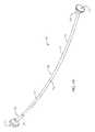
- FIG. 1Ais a left perspective view of an adjustable curved tension-mounted rod assembly in accordance with a preferred embodiment of the present invention
- FIG. 1Bis an enlarged perspective view of one end of the adjustable curved tension-mounted rod assembly shown in FIG. 1A ;
- FIG. 1Cis an exploded perspective view of the one end of the adjustable curved tension-mounted rod assembly shown in FIG. 1A ;
- FIG. 2Ais a front elevational view of an adjustable curved tension-mounted rod assembly in accordance with a preferred embodiment of the present invention
- FIG. 2Bis a top plan partial cross-sectional view of the adjustable curved tension-mounted rod assembly taken along line B-B of FIG. 2A ;
- FIG. 2Cis an enlarged top plan cross-sectional view of the adjustable curved tension-mounted rod assembly taken about area 2 C of FIG. 2B ;
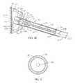
- FIG. 3is an enlarged elevational cross-sectional view of a fourth tube of the adjustable curved tension-mounted rod assembly shown in FIG. 1A ;
- FIG. 4is a left perspective cross-sectional view of an adjustable curved tension-mounted rod assembly in accordance with a preferred embodiment of the present invention.
- FIG. 4Ais an enlarged left perspective cross-sectional view of the adjustable curved tension-mounted rod assembly taken about area A of FIG. 4 .
- FIGS. 1A-1Ca presently preferred embodiment of an adjustable curved tension-mounted rod assembly in accordance with the present invention.
- the adjustable curved tension-mounted rod assemblypreferably functions as an adjustable curved curtain rod assembly, generally designated 10 .
- the adjustable curved rod assembly 10can be secured between two opposing support surfaces (not shown), such as bathroom walls.
- the adjustable curved rod assembly 10can be used as a shower curtain rod, or as a standard curtain rod.
- the adjustable curved rod assembly 10comprises a generally curved rod 12 that may be positioned and maintained between two opposing support surfaces or walls.
- the generally curved rod 12comprises a first, inner tube 14 having an arcuate portion and a second, outer tube 16 having an arcuate portion.
- the first, inner arcuate tube 14has a first end 14 a and a second end 14 b .
- the second, outer arcuate tube 16has a first end 16 a and a second end 16 b .
- the second end 16 b of the second tube 16is provided with a pair of diametrically opposed apertures 17 (only shown in FIG. 2B ).
- the first and second tubes 14 , 16are preferably made from a metal, and more preferably a non-corrosive metal, such as cold-rolled steel, stainless steel, aluminum, chrome or nickel or alloys or combinations thereof, but may also be constructed using wood, plastic, acrylic, or a like strong, lightweight material or a combination of materials.
- the first and second tubes 14 , 16may also be coated with any type of known coating for applying a non-corrosive finish to the curved rod 12 .
- the first and second tubes 14 , 16are both preferably generally cylindrical in shape with a circular cross section. However, it will be understood by those skilled in the art that any other suitable cross-sectional shape may be used, including oval, square, rectangular, hexagonal, octagonal, and the like.
- the outer diameter of the first tube 14is at least slightly smaller than the inner diameter of the second tube 16 , such that first tube 14 is telescopingly received within the second tube 16 in a reasonably tight fit. More particularly, in an assembled position of the adjustable curved rod assembly 10 , the second end 14 b of the first tube 14 is telescopingly positioned or received within the first end 16 a of the second tube 16 . Accordingly, the first and second tubes 14 , 16 of the curved rod 12 are telescopingly configured.
- the first tube 14preferably includes a spring-loaded pin 80 is configure to project from an exterior surface of the first tube 14 .
- the spring-loaded pin 80preferably has a first, relaxed position, in which the pin 80 projects outwardly away from the exterior surface of the first tube 14 , and a second, retracted position, in which the pin 80 is retracted or pushed inwardly toward the exterior surface of the first tube 14 .
- the pin 80is preferably biased toward the first, relaxed position.
- the second tube 16is provided with a plurality of spaced-apart apertures 82 , each of a sufficient size so as to be configured to receive the pin 80 . More particularly, the diameter of each aperture 82 is preferably of a sufficient size so as to allow the pin 80 to pass therethrough.
- a userIn order to adjust the length of the curved rod 12 , a user must first place the pin 80 in the second, retracted position, such as by pushing the pin 80 inwardly toward the first tube 14 . Next, the user adjusts the curved rod 12 to the desired length by moving the telescoping first and second tubes 14 , 16 toward each other to reduce the length of the curved rod 12 or away from each other to increase the length of the curved rod 12 . Once the desired length is achieved and the pin 80 is aligned with one of the plurality of apertures 82 , the pin 80 automatically transitions to its first, relaxed position, to which it is biased, by pass through the aperture 82 of the second tube 16 with which it is aligned. The engagement between the pin 80 of the first tube 14 and one of the apertures 82 of the second tube 16 ensures that the curved rod 12 maintains the desired length when secured between opposing support surfaces.
- the second tube 16preferably includes a protrusion 84 which extends from an interior surface of the second tube 16 toward an interior of the second tube 16 .
- the protrusion 84is preferably a rivet 84 which acts as a travel stop for the first tube 14 , such that the position of the rivet 84 is determinate of the overall length of the curved rod 12 . Specifically, once the first end 14 a of the first tube 14 contacts the rivet 84 , the first tube and second tubes 14 , 16 cannot move any further toward each other to reduce the length of the curved rod 12 .
- the curved rod 12has a pre-determined maximum length which is attained by moving the telescoping first and second tubes 14 , 16 toward each other until the first end 14 a of the first tube 14 contacts the rivet 84 .
- a rivet 84as a travel stop
- any appropriate travel stop structuremay be used.
- the interior of the second tube 16may be provided with a welded pin, a welded protrusion, a protruding rib, and the like, as long as the interior of the second tube 16 includes some structure which contacts and prevents further movement of the first tube 14 .
- the rivet 84is provided at a position along a length of the outer tube 16 , such that the resulting overall length of the adjustable curved rod assembly 10 is sufficient to span a distance of 60 inches.
- the rivet 84may be provided at any position along the length of the outer tube 16 , depending upon the desired overall lengths of the curved rod 12 and the adjustable curved rod assembly 10 .
- the adjustable curved rod assembly 10further comprises a third tube 30 which is preferably generally cylindrical in shape with a circular cross section and which preferably has a generally straight configuration.
- the third tube 30is preferably a rotatable tube 30 having a first end 30 a and a second end 30 b . More preferably, the first and second ends 30 a , 30 b of the rotatable tube 30 are open ends.
- the rotatable tube 30is preferably made from a metal, and more preferably a non-corrosive metal, such as cold-rolled steel, stainless steel, aluminum, chrome or nickel or alloys or combinations thereof, but may also be constructed using wood, plastic, acrylic, or a like strong, lightweight material or a combination of materials.
- the rotatable tube 30may also be coated with any type of known coating for applying a non-corrosive finish to the tube 30 . More preferably, the rotatable tube 30 is made from the same material as the first and second tubes 14 , 16 of the curved rod 12 .
- the inner diameter of the rotatable tube 30is at least slightly larger than the outer diameter of the first tube 14 of the curved rod 12 , such that the first end 14 a of the first tube 14 is configured to pass through the open second end 30 b and at least slightly into the rotatable tube 30 . Accordingly, in the assembled position of the adjustable curved rod assembly 10 , the first end 14 a of the first tube 14 is telescopingly positioned or received within the second end 30 b of the rotatable tube 30 (see FIG. 2C ).
- the longitudinal axis L 1 of the rotatable tube 30is preferably generally aligned with the longitudinal axis L 2 of the first end 14 a of the first tube 14 .
- the rotatable tube 30is preferably freely rotatable relative to the first tube 14 of the curved rod 12 positioned therein.
- the rotatable tube 30 and the first end 14 a of the first tube 14 of the curved rod 12are each at least partially hollow, such that a tension mechanism 20 can be fitted therein (see FIGS. 1C and 2C ). More specifically, the tension mechanism 20 is fixedly secured within an interior of the rotatable tube 30 , and more preferably within the first end 30 a of the rotatable tube 30 , such that the tension mechanism 20 is configured to rotate with the rotatable tube 30 .
- U.S. Pat. No. 5,330,061which is assigned to Zenith Products Corp. and is incorporated herein by reference, describes a preferred embodiment of a tension mechanism of the type for use in the adjustable curved rod assembly 10 .
- the tension mechanism 20 of the adjustable curved rod assembly 10is preferably a tension rod mechanism 20 comprising a rod 22 having a first end 22 a , a second end 22 b , a first stop piece 24 and a second stop piece 26 .
- the first stop piece 24is provided at the first end 22 a of the rod 22
- the second stop piece 26is positioned in between the first and second ends 22 a , 22 b .
- the first and second stop pieces 24 , 26may be shaped differently, as shown in FIG. 2C , or alternatively may have substantially identical structures. As will be discussed more fully herein, the first and second stop pieces 24 , 26 define the limits to which the overall length of the adjustable curved rod assembly 10 can be adjusted.
- the rod 22comprises a threaded portion 28 and a connector portion 60 .
- the threaded portion 28 of the rod 22is defined by the portion of the rod 22 having an external thread pattern.
- at least one part of the threaded portion 28 of the rod 22is flexible. More preferably, the entirety of the threaded portion 28 of the rod 22 is flexible.
- a portion or the entirety of the threaded portion 28 of the rod 22may alternatively be generally rigid.
- the connector portion 60 of the rod 22preferably comprises a connector 62 .
- a locking pin 64is integrally formed with the connector 62 .
- the locking pin 64may be formed as a separate component which is secured to the connector 62 by any conventional means.
- the locking pin 64protrudes outwardly away from a surface of the connector 62 and the threaded portion 28 of the rod 22 .
- the threaded portion 28 of the rod 22extends from the first end 22 a of the rod 22 and the first stop piece 24 to the second stop piece 26 .
- the connector portion 60preferably extends from the second stop piece 26 to the second end 22 b of the rod 22 , with the connector 62 defining the second end 22 b of the rod 22 .
- the first end 14 a of the first tube 14is telescopingly positioned within the interior of the rotatable tube 30 , the connector portion 60 of the tension mechanism 20 is fixedly secured within the first end 30 a of the rotatable tube 30 and at least a portion of the threaded portion 28 of the rod 22 extends into and is rotatably secured within the first end 14 a of the first tube 14 .
- the connector 62 of the rod 22is fixedly secured within the first end 30 a of the rotatable tube 30 and at least a portion of the threaded portion 28 of the rod 22 extends from an interior of the rotatable tube 30 to an interior of the first end 14 a of the first tube 14 . Accordingly, rotation of the rotatable tube 30 about the longitudinal axis L 1 thereof, relative to the first tube 14 , also causes rotation of the rod 22 of the tension mechanism 20 relative to the first tube 14 .
- At least a portion of an interior surface of the first end 14 a of the first tube 14preferably includes a threaded portion which is configured to threadingly engage the threaded portion 28 of the rod 22 to rotatably secure the rod 22 within the first tube 14 .
- the interior of the first end 14 a of the first tube 14includes a threaded bushing or nut 70 configured to threadingly engage the threaded portion 28 of the rod 22 to rotatably secure the rod 22 therein.
- the threaded bushing 70is preferably fixedly secured within the first end 14 a of the first tube 14 . More preferably, the threaded bushing 70 is positioned substantially a distal-most tip of the first end 14 a of the first tube 14 .
- the threaded bushing 70may be positioned at some other location within the first tube 14 , as long as the location allows extension and collapse of the adjustable curved rod assembly 10 to the desired length.
- the threaded bushing 70is preferably made from a metal, such as cold-rolled steel, stainless steel, aluminum, chrome or nickel or alloys or combinations thereof, but may also be constructed using wood, plastic, acrylic, or a like strong, lightweight material or a combination of materials.
- the threaded bushing 70may be secured within the first tube 14 by any conventional means, such as a flange connection, a dimple connection, adhesives, welds and the like.
- the threaded bushing 70is secured within the first end 14 a of the first tube 14 by a flange 15 which extends circumferentially from the threaded bushing 70 around the distal-most tip of the first end 14 a of the first tube 14 .
- an exterior surface of the threaded bushing 70is in direct contact with an interior surface of the first tube 14 .
- An interior surface of the threaded bushing 70is preferably defined by a centrally located and threaded through-hole 72 .
- the thread pattern of the through-hole 72corresponds to or complements that of the threaded portion 28 of the rod 22 .
- the centrally located through-hole 72 of the threaded bushing 70also includes an inner diameter that is substantially equal to the outer diameter of the threaded portion 28 of the rod 22 .
- the threaded portion 28 of the rod 22is positioned within the centrally located through-hole 72 of the threaded bushing 70 , such that the threaded portion 28 of the rod 22 rotates within the threaded bushing 70 .
- rotation of the rotatable tube 30causes the first tube 14 and the rotatable tube 30 to move axially relative to each other. More particularly, rotation of the rotatable tube 30 in a first direction about the longitudinal axis L 1 thereof preferably causes the first tube 14 and the rotatable tube 30 to move axially away from each other, thereby extending the overall length of the adjustable curved rod assembly 10 .
- Rotation of the rotatable rod 30 in the first direction, and more particularly movement of the threaded portion 28 within the threaded bushing 70 as the rotatable rod 30 is rotated in the first directionis preferably limited by the second stop piece 26 .
- Rotation of the rotatable tube 30 in a second direction, opposite the first direction, about the longitudinal axis L 1 thereofpreferably causes the first tube 14 and the rotatable tube 30 to move axially toward each other, thereby reducing the overall length of the adjustable curved rod assembly 10 .
- Rotation of the rotatable rod 30 in the second direction, and more particularly movement of the threaded portion 28 within the threaded bushing 70 as the rotatable rod 30 is rotated in the second directionis preferably limited by the first stop piece 24 .
- the adjustable curved rod assembly 10further comprises a fourth tube 46 which is preferably generally cylindrical in shape with a circular cross section and which preferably has a generally straight configuration.
- the fourth tube 46is preferably a generally cylindrical coupler 46 .
- the coupler 46has a first end 46 a and a second end 46 b .
- the coupler 46preferably includes at least one generally closed interior and intermediate wall 48 at a position between the opposing first and second ends 46 a , 46 b .
- the interior and intermediate wall 48includes an aperture or groove 48 a centrally formed therein. More preferably, the interior and intermediate wall 48 includes a centrally-located aperture 48 a formed therethrough.
- the first end 46 a of the coupler 46preferably includes a pair of diametrically opposed apertures 50 .
- the inner diameter of the coupler 46is slightly larger than the outer diameter of the rotatable tube 30 , such that the rotatable tube 30 can be positioned within an interior of the coupler 46 . More particularly, in the assembled position of the adjustable curved rod assembly 10 , the first end 30 a of the rotatable tube 30 is telescopingly position and received within the second end 46 b of the coupler 46 . Preferably, the rotatable tube 30 is rotatably secured within the coupler 46 , such that the rotatable tube 30 is freely rotatable relative to the coupler 46 .
- the preferred structural configuration of the rotatable tube 30 and the coupler 46is achieved by rotational engagement of the locking pin 64 and the aperture or groove 48 a of the intermediate wall of the coupler 46 . More particularly, in one embodiment, the first end 30 a of the rotatable tube 30 , in which the connector 62 of the tension mechanism 20 is fixedly secured, is positioned within the second end 46 b of the coupler 46 until the locking pin 64 of the connector 62 passes through the aperture 48 a of the intermediate wall 48 .
- At least a portion of the locking pin 64has a diameter which is at least slightly larger than that of the aperture 48 a , such that once the locking pin 64 is positioned within the aperture 48 a (e.g., by snapping the locking pin 64 into position), the locking pin 64 is frictionally engaged by the aperture 48 a and is not easily detached or removed from the aperture 48 a.
- Such an engagement between the tension mechanism 20 and the coupler 46secures the tension mechanism 20 to the coupler 46 in a stable manner, while simultaneously enabling both the rotatable tube 30 and the tension mechanism 20 to rotate relative to the coupler 46 and the first tube 14 of the curved rod 12 , as necessary for adjustment of the overall length of the adjustable curved rod assembly 10 and the generation of a tensile or compressive force which holds the adjustable curved rod assembly 10 in place between opposing supporting surfaces. More particularly, rotation of the rotatable tube 30 in the first direction about the longitudinal axis L 1 thereof preferably causes the first tube 14 and the coupler 46 to move axially away from each other, thereby extending the overall length of the adjustable curved rod assembly 10 to create the needed tension against the opposing support surfaces.
- rotation of the rotatable tube 30 in the second, opposite direction, about the longitudinal axis L 1 thereofpreferably causes the first tube 14 and the coupler 46 to move axially toward each other, thereby reducing the overall length of the adjustable curved rod assembly 10 .
- the coupler 46is preferably made from a metal, and more preferably a non-corrosive metal, such as cold-rolled steel, stainless steel, aluminum, chrome or nickel or alloys or combinations thereof, but may also be constructed using wood, plastic, acrylic, or a like strong, lightweight material or a combination of materials.
- the coupler 46may also be coated with any type of known coating for applying a non-corrosive finish to the coupler 46 .
- the coupler 46is made from the same material as the first and second tubes 14 , 16 of the curved rod 12 and the rotatable tube 30 .
- the adjustable curved rod assembly 10further comprises a first end support 32 and a second end support 34 .
- Each of the first and second end supports 32 , 34is configured to be removably mounted to a respective support surface (not shown) of the two opposing support surfaces.
- the coupler 46is secured to the first end support 32 and the second tube 16 of the curved rod 12 is secured to the second end support 34 . More preferably, the first end support 32 receives the first end 46 a of the coupler 46 in a stable manner.
- the second end support 34receives the second end 16 b of the second tube 16 in a similarly stable manner.
- first end and second end supports 32 , 34are preferably made from a lightweight, high strength material, such as aluminum or steel, but could be made of other materials, such as a polymeric material, chrome or nickel, or alloys or combinations thereof, but may also be constructed using wood, plastic, acrylic, or a like strong, lightweight material or a combination of materials without departing from the spirit and scope of the invention.
- first and second end supports 32 , 34are made from the same material as the first and second tubes 14 , 16 of the curved rod 12 , the rotatable tube 30 and the coupler 46 .
- One or both of the first and second end supportsmay optionally be provided with a decorative cover 33 .
- the first end support 32is preferably a mirror image of the second end support 34 .
- first end support 32is described in detail and completely labeled in the drawings with the understanding that the second end support 34 includes similar features.
- the first end support 32includes a base plate 36 having a first, rear face 36 a and an opposing second, front face 36 b .
- a resilient pad 38is secured to the rear surface 36 a of the base plate 36 and is configured to directly contact one of the opposing support surfaces to support the adjustable curved rod assembly 10 above a ground surface when the assembly is installed.
- the resilient pad 38may be made of a rubber (natural or synthetic), foam, an elastomeric plastic or any other resilient material having a sufficiently high coefficient of friction to ensure secure mounting of the adjustable curved rod assembly 10 between the two opposing support surfaces.
- a first flange 40 and a second flange 42extend generally perpendicularly from the front face 36 b of the base plate 36 of the first end support 32 .
- the first and second flanges 40 , 42are spaced apart from each other so as to form a support space 44 therebetween.
- a first aperture 40 ais formed in the first flange 40 and a second aperture 42 a is formed in the second flange 42 .
- the first and second apertures 40 a , 42 aare generally aligned or in registry with each other.
- a first fastener assemblycomprising a first fastening pin 52 and a first fastening pin end 54 is preferably utilized to secure the coupler 46 within the support space 44 formed between the first and second flanges 40 , 42 .
- the first end 46 a of the coupler 46is positioned within the support space 44 , such that the apertures 50 of the first end 46 a of the coupler 46 are aligned or in registry with the first and second apertures 40 a , 42 a of the first and second flanges 40 , 42 .
- the first fastening pin 52 and the first fastening pin end 54are then inserted through the first and second apertures 40 a , 42 a of the first end support 32 and the apertures 50 of the coupler 46 .
- the first fastening pin 52may be secured within the first fastening pin end 54 by any known conventional mechanisms, such as corresponding thread patterns, an adhesive, friction fit, an interference fit and the like.
- the coupler 46and more particularly the first end 46 a of the coupler 46 , is pivotably secured to the first end support 32 .
- the coupler 46may alternatively be fixedly secured to the first end support 32 .
- the second end 16 b of the second tube 16is similarly pivotably secured to the second end support 34 by a second fastening assembly comprising a second fastening pin 52 and a second fastening pin end 54 engages the first and second apertures 40 a , 42 a of the second end support 34 and the apertures 17 of the second end 16 b of the second tube 16 .
- a second fastening assemblycomprising a second fastening pin 52 and a second fastening pin end 54 engages the first and second apertures 40 a , 42 a of the second end support 34 and the apertures 17 of the second end 16 b of the second tube 16 .
- the second end 14 b of the first tube 14is positioned within the first end 16 a of the second tube 16 of the curved rod 12 , such that the first and second tubes 14 , 16 are telescopingly configured;
- the first end 14 a of the first tube 14 of the curved rod 12is positioned within the second end 30 b of the rotatable tube 30 such that the first tube 14 and the rotatable tube 30 are telescopingly configured and the rotatable tube 30 is freely rotatable relative to the first tube 14 ;
- the connector portion 60 of the rod 22 of the tension mechanism 20is fixedly secured within the first end 30 a of the rotatable tube 30 and at least a portion of the threaded portion 28 of the rod 22 extends from the rotatable tube 30 into the first tube 14 where it is rotatably secured therein by the threaded bushing 70 ;
- the first end 30 a of the rotatable tube 30is rotatably secured within the second end 46
- the other end of the assembly 10is rotatably secured to the first end support 32 . More particularly, while the coupler 46 is pivotably secured to the first end support 32 , the rotatable tube 30 remains rotatable relative to the first end support 32 . Thus, the rotatable tube 30 is rotatably secured to the first end support 32
- the assembly 10is positioned between the opposing support surfaces of the stall and the length of the curved rod 12 is adjusted until the initial desired length is achieved.
- the length of the curved rod 12is adjusted by sliding the first and second tubes 14 , 16 either toward or away from each other until the desired length is achieved and the spring-loaded pin 80 is received within a cooperating hole 82 .
- the engagement between the pin 80 of the first tube 14 and a hole 82 of the second tube 16ensures that the curved rod 12 maintains the desired length when secured between opposing support surfaces.
- the initial desired length of the curved rod 12is dependent upon the distance between the opposing support surfaces and is achieved when the rear face 36 a of the base plate 36 (or the resilient pad 38 attached thereto) of each end support 32 , 34 is proximate a respective opposing support surface. More preferably, the initial desired length of the curved rod 12 is achieved when the rear face 36 a of the base plate 36 or (the resilient pad 38 attached thereto) of each end support 32 , 34 directly contacts or almost directly contacts a respective opposing support surface at generally the same height, such that the first and second tubes 14 , 16 are generally horizontal in the mounted configuration.
- the rotatable tube 30can be manually rotated by a user to generate a tension or compressive force to be exerted by the adjustable curved rod assembly 10 upon the opposing support surfaces, such that the assembly 10 is maintained between the two opposing surfaces without the use of fasteners or adhesives.
- the usermanually rotates the rotatable tube 30 about its longitudinal axis L 1 , thereby adjusting the overall desired length of the rod assembly 10 , until the rear surface 36 a of the base plate 36 or (the resilient pad 38 attached thereto) of each end support 32 , 34 directly contacts a respective opposing support surface and a compressive or tensile force, generated by the tension mechanism 20 , is applied or exerted against the opposing support surfaces.
- a compressive or tensile forceis also generated and exerted between the threads of bushing 70 and the threads of threaded portion 28 to maintain the position of bushing 70 along the threaded portion 28 .
- the adjustable curved rod assembly 10is maintained between the two opposing surfaces without the use of fasteners or adhesives.
Landscapes
- Mutual Connection Of Rods And Tubes (AREA)
- Curtains And Furnishings For Windows Or Doors (AREA)
Abstract
Description
Claims (20)
Priority Applications (5)
| Application Number | Priority Date | Filing Date | Title |
|---|---|---|---|
| US13/676,800US9271592B2 (en) | 2012-11-14 | 2012-11-14 | Adjustable tension-mounted curved rod assembly |
| US13/911,191US9107529B2 (en) | 2012-11-14 | 2013-06-06 | Adjustable tension-mounted curved rod assembly |
| CA2830942ACA2830942A1 (en) | 2012-11-14 | 2013-10-24 | Adjustable tension-mounted curved rod assembly |
| MX2013013275AMX2013013275A (en) | 2012-11-14 | 2013-11-13 | Adjustable tension-mounted curved rod assembly. |
| US14/465,355US9131795B2 (en) | 2012-11-14 | 2014-08-21 | Adjustable tension-mounted curved rod assembly |
Applications Claiming Priority (1)
| Application Number | Priority Date | Filing Date | Title |
|---|---|---|---|
| US13/676,800US9271592B2 (en) | 2012-11-14 | 2012-11-14 | Adjustable tension-mounted curved rod assembly |
Related Child Applications (1)
| Application Number | Title | Priority Date | Filing Date |
|---|---|---|---|
| US13/911,191Continuation-In-PartUS9107529B2 (en) | 2012-11-14 | 2013-06-06 | Adjustable tension-mounted curved rod assembly |
Publications (2)
| Publication Number | Publication Date |
|---|---|
| US20140131298A1 US20140131298A1 (en) | 2014-05-15 |
| US9271592B2true US9271592B2 (en) | 2016-03-01 |
Family
ID=50680666
Family Applications (1)
| Application Number | Title | Priority Date | Filing Date |
|---|---|---|---|
| US13/676,800Active2034-04-10US9271592B2 (en) | 2012-11-14 | 2012-11-14 | Adjustable tension-mounted curved rod assembly |
Country Status (3)
| Country | Link |
|---|---|
| US (1) | US9271592B2 (en) |
| CA (1) | CA2830942A1 (en) |
| MX (1) | MX2013013275A (en) |
Cited By (30)
| Publication number | Priority date | Publication date | Assignee | Title |
|---|---|---|---|---|
| US20170238767A1 (en)* | 2014-09-11 | 2017-08-24 | Croydex Limited | Improvements in or relating to shower rods |
| US10051985B2 (en)* | 2016-05-23 | 2018-08-21 | Moen Incorporated | Shower rod |
| US10314442B2 (en)* | 2017-06-16 | 2019-06-11 | Audrey Fields | Shower curtain assembly |
| US10448762B2 (en) | 2017-09-15 | 2019-10-22 | Kohler Co. | Mirror |
| USD864701S1 (en)* | 2019-01-30 | 2019-10-29 | Jiarui Huang | Installation rod head of shower curtain rod |
| US10458452B2 (en)* | 2018-02-13 | 2019-10-29 | Town & Country Linen Corp. | Tension rod and pivotable end caps for use therewith |
| US10663938B2 (en) | 2017-09-15 | 2020-05-26 | Kohler Co. | Power operation of intelligent devices |
| USD899895S1 (en) | 2018-02-23 | 2020-10-27 | House of Atlas, LLC | Surface mount |
| US10887125B2 (en) | 2017-09-15 | 2021-01-05 | Kohler Co. | Bathroom speaker |
| US10959559B2 (en) | 2019-03-08 | 2021-03-30 | House of Atlas, LLC | Dual-mounted end cap system and locking system for an adjustable rod |
| US11093554B2 (en) | 2017-09-15 | 2021-08-17 | Kohler Co. | Feedback for water consuming appliance |
| US11099540B2 (en) | 2017-09-15 | 2021-08-24 | Kohler Co. | User identity in household appliances |
| US11215217B2 (en) | 2018-02-23 | 2022-01-04 | House of Atlas, LLC | Surface mount |
| US11266263B2 (en) | 2015-09-16 | 2022-03-08 | House of Atlas, LLC | Support bracket for rod assembly |
| US20220160158A1 (en)* | 2020-11-25 | 2022-05-26 | Decolin Inc. | Adjustable telescoping tension rods |
| US11382447B2 (en) | 2019-07-30 | 2022-07-12 | House of Atlas, LLC | Adjustable rod features |
| US11452398B2 (en) | 2020-01-22 | 2022-09-27 | House of Atlas, LLC | Bracket for surface mounting |
| US11624472B1 (en)* | 2021-08-06 | 2023-04-11 | Art Guild, Inc. | System for supporting an elongated member |
| USD1005084S1 (en) | 2020-01-21 | 2023-11-21 | Olson Ip Technologies, Inc. | Suction cup mount |
| US11825940B2 (en) | 2020-05-18 | 2023-11-28 | House of Atlas, LLC | Customizable shower caddy |
| US11857098B2 (en) | 2020-06-04 | 2024-01-02 | House of Atlas, LLC | Curved curtain rod |
| US20240016328A1 (en)* | 2022-06-08 | 2024-01-18 | Crompton Ventures, Llc | System and method for supporting a privacy curtain including a swing arm wall mount and end stop cap support |
| US11889958B2 (en) | 2019-04-17 | 2024-02-06 | House of Atlas, LLC | Rotating shower rod |
| US11974704B2 (en) | 2022-03-03 | 2024-05-07 | House Of Atlas Llc | Customizable shower caddy |
| US12031565B2 (en) | 2020-01-10 | 2024-07-09 | Olson Ip Technologies, Inc. | Suction mount and brackets and accessories therefor |
| US12049980B1 (en) | 2021-08-06 | 2024-07-30 | Art Guild of Philadelphia, Inc. | System for securing an elongated member |
| US12082733B2 (en) | 2022-09-23 | 2024-09-10 | House of Atlas, LLC | Mounting bracket |
| US12251040B2 (en) | 2023-02-03 | 2025-03-18 | House of Atlas, LLC | Mounting bracket |
| US12303053B1 (en) | 2023-11-14 | 2025-05-20 | House of Atlas, LLC | Spring-biased end caps for rod assembly and methods of use |
| US20250235025A1 (en)* | 2024-01-19 | 2025-07-24 | House of Atlas, LLC | Rod Connector System and Methods of Use |
Families Citing this family (8)
| Publication number | Priority date | Publication date | Assignee | Title |
|---|---|---|---|---|
| US9204764B1 (en)* | 2011-11-02 | 2015-12-08 | Kenney Manufacturing Company | Curved shower rod with oblong brackets and center screw |
| US8978228B2 (en)* | 2012-11-14 | 2015-03-17 | Zenith Products Corporation | Adjustable rod assembly |
| US9033163B2 (en)* | 2013-07-30 | 2015-05-19 | Test Rite Products Corp. | Curved shower rod assembly having flexible mounting base |
| US11839337B2 (en)* | 2021-05-27 | 2023-12-12 | Component Sourcing International, LLC | Shower rod assembly |
| USD1002350S1 (en)* | 2021-10-15 | 2023-10-24 | Wuhu Yijiale Metal Products Co., Ltd. | Adjustable telescopic rod |
| USD972396S1 (en)* | 2022-04-15 | 2022-12-13 | Shenzhen Bosaixi Innovation Technology Co., Ltd. | Tension curtain rod |
| CN114983219A (en)* | 2022-07-12 | 2022-09-02 | 东莞市盛泓家居用品有限公司 | Telescopic shower curtain rod and space adaptability installation method thereof |
| USD1070579S1 (en)* | 2023-06-28 | 2025-04-15 | Yuyao Yuxiong Sanitary Equipment Co. Ltd | Shower curtain rod |
Citations (269)
| Publication number | Priority date | Publication date | Assignee | Title |
|---|---|---|---|---|
| US653642A (en) | 1897-10-11 | 1900-07-10 | American Bicycle Company | Handle-bar. |
| US839959A (en) | 1906-05-09 | 1907-01-01 | Thomas C Richards | Supporting-bracket for curtain-rods. |
| US972544A (en) | 1910-06-24 | 1910-10-11 | H L Judd Company | Connection for curtain-rods and the like. |
| US1253486A (en) | 1917-03-16 | 1918-01-15 | Edna I Hammer | Adjustable supporting-rod. |
| US1299556A (en) | 1917-12-26 | 1919-04-08 | Multiplex Display Fixture Company | Supporting-pole and bracket therefor. |
| FR499003A (en) | 1919-05-05 | 1920-01-29 | Leon Bernard | Slide rod for double curtains |
| US1481730A (en) | 1921-10-19 | 1924-01-22 | Bridgeport Brass Co | Towel rack or like fixture |
| US1487017A (en) | 1922-01-11 | 1924-03-18 | Lilja Bert Henry | Curtain rod |
| US1502154A (en) | 1923-05-25 | 1924-07-22 | Adolph Mueller | Noslip flange |
| US1646011A (en) | 1925-11-16 | 1927-10-18 | Constantine Shickralla | Window-shade and curtain-rod holder |
| US1675111A (en) | 1927-12-14 | 1928-06-26 | Kenney Mfg Co | Curtain-rod bracket |
| US1679881A (en) | 1925-10-05 | 1928-08-07 | Herbert A Simpson | Hanger rod |
| US1721305A (en) | 1924-12-09 | 1929-07-16 | Eustachius W Koering | Towel bar |
| US1721306A (en) | 1926-06-29 | 1929-07-16 | Eustachius W Koering | Towel bar |
| US1837340A (en) | 1931-09-17 | 1931-12-22 | Schwartz Meyer | Curtain rod |
| US1951660A (en) | 1933-11-20 | 1934-03-20 | Helmuth R Klaudt | Adjustable supporting bar |
| US1953450A (en) | 1933-12-29 | 1934-04-03 | Thompson Ellis | Curtain and drapery fixture |
| US2032842A (en) | 1935-10-23 | 1936-03-03 | Charles W Gould | Adjustable spring curtain rod |
| US2131156A (en) | 1937-02-02 | 1938-09-27 | James W Yardley | Shower curtain position retainer |
| US2150204A (en) | 1938-11-09 | 1939-03-14 | Boye James H Mfg Co | Curtain fixture |
| US2194064A (en) | 1938-12-01 | 1940-03-19 | Boye James H Mfg Co | Center bracket for curtain rods |
| US2195979A (en) | 1938-06-22 | 1940-04-02 | Ziolkowski Alex | Curtain and drapery support |
| US2199851A (en) | 1938-07-16 | 1940-05-07 | Culver John Freeman | Shower curtain rod |
| US2215331A (en) | 1939-03-10 | 1940-09-17 | Marsh Daniel | Fixture |
| US2219075A (en) | 1938-09-13 | 1940-10-22 | Veau Eugene Le | Curtain support |
| US2250003A (en) | 1941-01-27 | 1941-07-22 | Boye James H Mfg Co | Window cornice |
| US2263698A (en) | 1941-05-10 | 1941-11-25 | James A Hodgson | Safety bar for automobiles |
| US2293168A (en) | 1940-07-18 | 1942-08-18 | Pirone Amato Mario Matthew | Hanger bar |
| US2383104A (en) | 1943-12-27 | 1945-08-21 | Kirsch Co | Curtain rod or drapery fixture |
| US2458643A (en) | 1947-01-15 | 1949-01-11 | Earl W Riley | Bracket for drapery fixtures |
| US2462321A (en) | 1945-12-19 | 1949-02-22 | Clarence W Carlson | Rack |
| US2519996A (en) | 1948-02-09 | 1950-08-22 | Blake Ralph | Adjustable curtain rod |
| US2562371A (en) | 1948-10-12 | 1951-07-31 | James F Shannon | Fireplace screen support |
| US2594049A (en) | 1949-09-10 | 1952-04-22 | Matos Nicanor | Bathtub curtain frame |
| US2594605A (en) | 1946-12-23 | 1952-04-29 | Rop Loc Products Co | Adjustable supporting bar |
| US2608420A (en) | 1949-01-03 | 1952-08-26 | Frank T Eck | Load bracing structure for vehicles |
| US2637555A (en) | 1950-07-07 | 1953-05-05 | Helmuth R Klaudt | Exercise bar |
| US2741923A (en) | 1951-01-20 | 1956-04-17 | Bradley Rotor Traverse Company | Apparatus for traversing draperies and the like |
| US2760745A (en) | 1954-04-23 | 1956-08-28 | Mccleery Dwight | Implement for holding wallpaper steamer |
| US2778030A (en)* | 1954-01-14 | 1957-01-22 | Goche Jean | Shower stall |
| US2796227A (en) | 1954-03-05 | 1957-06-18 | Claude A Coakley | Bracket for a movable shower curtain rod |
| US2870918A (en) | 1956-05-31 | 1959-01-27 | Grubbs Emmett Leroy | Adjustable curtain, blind and drape holder |
| US2915327A (en) | 1953-06-30 | 1959-12-01 | Walter J Kreske | Locking mechanisms for telescoping members |
| US2919134A (en) | 1958-03-10 | 1959-12-29 | Walter Ratner | Mechanical exerciser |
| US2927762A (en) | 1957-09-26 | 1960-03-08 | Owsiak Joseph | Quick detachable adjustable bracket for curtain rods |
| US2974806A (en) | 1957-06-27 | 1961-03-14 | Seewack Benjamin | Shower rod holder |
| US3023909A (en) | 1960-04-11 | 1962-03-06 | Stanley Works | Curtain rod assembly with protective device for preventing snagging |
| US3079005A (en) | 1960-08-18 | 1963-02-26 | Bednar Thelma | Drapery and curtain support apparatus |
| US3087982A (en) | 1959-12-01 | 1963-04-30 | Northrop Corp | Vacuum tube mounts |
| US3107361A (en) | 1961-12-26 | 1963-10-22 | Sr Roy H Glutting | Shower bath curtain |
| US3324613A (en) | 1966-09-21 | 1967-06-13 | Duboff Philip | Utility pole construction |
| US3333808A (en) | 1965-06-07 | 1967-08-01 | Shelfmaker Products Corp | Utility pole construction |
| US3418665A (en) | 1966-02-23 | 1968-12-31 | John C. Long | Shower installations |
| US3429452A (en) | 1967-04-13 | 1969-02-25 | Stanley Works | Telescoping support rod having universal end cap |
| US3493121A (en) | 1967-04-12 | 1970-02-03 | Stanley Works | Telescoping support rod and end cap therefor |
| US3504805A (en) | 1967-04-13 | 1970-04-07 | Stanley Works | Telescoping support rod and universal end cap therefor |
| US3521758A (en) | 1968-03-28 | 1970-07-28 | Edward C Guilfoyle Sr | Expansible hanger |
| US3557390A (en) | 1968-07-01 | 1971-01-26 | American Standard Inc | Tub and shower surround and apparatus and method for making same |
| US3572511A (en)* | 1968-07-26 | 1971-03-30 | Lee Triplett | Multiple member assembly |
| DE2051383A1 (en) | 1969-10-22 | 1971-05-13 | Sainsbury & Parkinson Ltd , Walsall, Staffordshire (Großbritannien) | Rod for towels or the like |
| US3687499A (en) | 1968-03-28 | 1972-08-29 | Edward C Guilfoyle Sr | Coupling devices |
| US3836174A (en)* | 1972-10-16 | 1974-09-17 | R Holman | Cargo beam |
| US3864760A (en) | 1972-04-26 | 1975-02-11 | Duane C Bowen | Bathing facility |
| US3965960A (en) | 1974-09-16 | 1976-06-29 | Massey Peyton L | Retractable shower shade with adjustable extensibility |
| USD248434S (en) | 1976-05-11 | 1978-07-11 | Franco Clivio | Hanger for garden utensils |
| US4117557A (en) | 1977-06-27 | 1978-10-03 | Mcpeak Walter G | Horizontally adjustable curtain rods for bathroom stalls |
| US4229842A (en) | 1979-04-20 | 1980-10-28 | Louis Gilmore | Shower curtain convertible support adapter |
| US4238164A (en) | 1979-03-13 | 1980-12-09 | H & G Industries, Inc. | Positive locking device for telescoping tubing |
| CH625601A5 (en) | 1978-01-11 | 1981-09-30 | Spirella Ag | Longitudinally adjustable construction element |
| US4329076A (en) | 1980-08-21 | 1982-05-11 | Lapides Corporation | Telescoping tubes with a twist locking arrangement |
| EP0058405A1 (en) | 1981-02-13 | 1982-08-25 | Rudolf Dipl.-Wirtsch.-Ing. Wilke | Method of fastening an object onto a wall by means of at least one support, and object to be fastened onto a wall by means of supports having fastening holes |
| US4378071A (en) | 1979-11-30 | 1983-03-29 | Yakimicki Elizabeth A | Clamp-on grab rail for doors |
| US4399917A (en) | 1981-06-11 | 1983-08-23 | Graber Industries, Inc. | Dual curtain rod assembly |
| US4461056A (en) | 1982-01-08 | 1984-07-24 | Walter Solinski | Shower and decorative curtain suspension for a bathroom stall |
| US4496059A (en) | 1981-04-13 | 1985-01-29 | Leiter Raymond J | Curtain bow |
| DE2460382C2 (en) | 1974-12-20 | 1986-04-17 | Rudolf Dipl.-Wirtsch.-Ing. 3548 Arolsen Wilke | Kit with at least one node element |
| US4586615A (en) | 1983-03-09 | 1986-05-06 | Spiralux Limited | Holder |
| US4635889A (en) | 1985-06-20 | 1987-01-13 | Cooper Industries | Drapery support system with decorative rod end support structure |
| US4636106A (en) | 1984-10-26 | 1987-01-13 | Tzora Furniture Industries Ltd. | Coaxial joint |
| US4650383A (en) | 1985-02-19 | 1987-03-17 | Hoff Phillip L | Cargo stabilizer for utility vehicles |
| US4653714A (en) | 1985-11-13 | 1987-03-31 | Andrasko Jr John | Hand rail |
| US4662593A (en) | 1986-01-17 | 1987-05-05 | Shames Sidney J | Concealed mounting for wall mounted supports formed of plastic |
| DE3539449A1 (en) | 1985-11-07 | 1987-05-21 | Erbsloeh Julius & August | Connection of lightweight metal profiles with connecting elements |
| US4700918A (en) | 1985-11-13 | 1987-10-20 | Andrasko Jr John | Hand rail |
| USD293297S (en) | 1985-08-19 | 1987-12-22 | Wood Nimrod P | Hanger for a cylindrical container |
| US4754504A (en) | 1986-03-05 | 1988-07-05 | Cellini William F | Shower enlarger |
| US4809401A (en) | 1987-04-13 | 1989-03-07 | Honig Michael R | Drapery pole installation system |
| USD301976S (en) | 1987-08-03 | 1989-07-04 | Greenhut Steven E | Holder for broom or similar article |
| US4895471A (en) | 1988-03-18 | 1990-01-23 | Zenith Products Corporation | Expander mechanism for telescoping tubes |
| US4979713A (en) | 1989-11-29 | 1990-12-25 | Gatco, Inc. | Towel rack mounting means |
| US5022104A (en) | 1990-07-31 | 1991-06-11 | Cedric C. Miller | Shower curtain support |
| US5056753A (en) | 1989-03-07 | 1991-10-15 | Lunau Kevin R | Safety support structure |
| US5103531A (en) | 1990-08-27 | 1992-04-14 | Joseph Perrotta | Shower bow |
| USD327421S (en) | 1991-07-30 | 1992-06-30 | Zenith Products Corporation | End cap for support rod |
| US5189759A (en) | 1991-10-21 | 1993-03-02 | Poore Frank A | Shower curtain rod unit |
| US5216766A (en) | 1992-03-31 | 1993-06-08 | Lang Randall P | Shower curtain rod attachment |
| US5236229A (en) | 1991-08-28 | 1993-08-17 | Emhart Inc. | Flange assembly with retention means |
| US5242065A (en) | 1992-12-14 | 1993-09-07 | Springs Window Fashions Division, Inc. | Curtain rod with lockable fitting |
| US5263594A (en) | 1990-07-20 | 1993-11-23 | Stanley Works (Italia) S.R.L. | Curtain rod for slidably supporting a curtain around an intermediate corner, and intermediate junction element therefor |
| US5281063A (en) | 1992-02-04 | 1994-01-25 | Austin Iii Ralph J | Cargo bar lock assembly |
| USD347784S (en) | 1992-02-05 | 1994-06-14 | I. W. Industries, Inc. | Finial ball |
| US5330061A (en) | 1993-03-17 | 1994-07-19 | Zenith Products Corporation | Spinning shower rod mechanism |
| US5402842A (en) | 1991-08-28 | 1995-04-04 | Ruggiero; Anthony J. | Shower curtain support |
| US5433551A (en) | 1994-01-12 | 1995-07-18 | Gordon; Larry D. | Telescoping rod assembly |
| US5477964A (en) | 1994-12-27 | 1995-12-26 | The Stanley Works | Package for an elongated tool |
| US5484056A (en) | 1994-12-14 | 1996-01-16 | Cooper Industries, Inc. | Display hanger having an elastomeric article retainer |
| CN2221357Y (en) | 1994-09-24 | 1996-03-06 | 郑韶生 | Telescopic rod of stainless steel |
| CN2228573Y (en) | 1995-08-01 | 1996-06-05 | 夏浩光 | Multi-purpose adjustable rod |
| USD374167S (en) | 1993-12-23 | 1996-10-01 | Hewi Heinrich Wilke Gmbh | Rod holder |
| US5561870A (en) | 1994-01-19 | 1996-10-08 | Hertel; Donald L. | Shower curtain rod attachment |
| USD376312S (en) | 1995-09-05 | 1996-12-10 | Lockwell Corporation | Screwdriver holder |
| USD377753S (en) | 1996-04-15 | 1997-02-04 | Meadows Robert S | Paint can caddy |
| US5603475A (en) | 1993-01-11 | 1997-02-18 | Lim; Yang-Mook | Rack structure |
| USD379297S (en) | 1996-03-21 | 1997-05-20 | Robert Shires | Shower curtain rod |
| US5662297A (en) | 1995-10-03 | 1997-09-02 | Christensen; James Richard | Adjustable shower curtain rod |
| USD385177S (en) | 1995-11-27 | 1997-10-21 | Perry Gordon K | Adjustable safety bar |
| US5678703A (en) | 1995-07-31 | 1997-10-21 | Sawyer; Gerald F. | Finial adapter for curtain rods |
| USD393390S (en) | 1997-01-29 | 1998-04-14 | Friedrich Grohe Ag | Bracket for a shower rod |
| US5803643A (en) | 1995-10-31 | 1998-09-08 | Patelli; Quinto | Device actuated and maintained by axial pressure for mutual locking of tubular sections of a telescopic tube |
| USD397928S (en) | 1996-10-31 | 1998-09-08 | Sean Moore | Curved shower curtain rod |
| GB2325397A (en) | 1997-05-22 | 1998-11-25 | Reville Ernest George Grey | Telescopic curtain support rod |
| US5876147A (en) | 1996-06-18 | 1999-03-02 | Longo; Renato | Locking device for telescopic rods |
| US5894610A (en) | 1996-12-20 | 1999-04-20 | Zenith Products Corp. | Shower rod mounting assembly |
| USD416785S (en) | 1999-05-01 | 1999-11-23 | Lai Ming-Hsiao | Safety hand support of toilet |
| CN2349932Y (en) | 1998-11-10 | 1999-11-24 | 新会市会城荣丰五金制品厂 | Telescopic airing rod |
| JP2000046021A (en) | 1998-07-30 | 2000-02-15 | Teramoto Corp | Telescopic rod and handled tool using this telescopic rod |
| USD423337S (en) | 1999-04-01 | 2000-04-25 | Lehigh Consumer Products Corporation | Double arm storage hook |
| USD423338S (en) | 1999-04-22 | 2000-04-25 | Lehigh Consumer Products Corporation | Adjustable overhead storage hook |
| USD426142S (en) | 1999-02-11 | 2000-06-06 | Sean Moore | Wall mount |
| USD429461S (en) | 1999-08-11 | 2000-08-15 | The Stanley Works | Hand tool package |
| US6101675A (en) | 1999-04-26 | 2000-08-15 | Source Global Enterprises, Inc. | Pivoting and telescoping curtain dual-rod bracket for bay windows |
| USD431460S (en) | 1999-03-05 | 2000-10-03 | Black & Decker Inc. | Display apparatus |
| USD438462S1 (en) | 1997-12-19 | 2001-03-06 | Black & Decker Inc. | Display apparatus |
| US6199808B1 (en) | 1999-10-21 | 2001-03-13 | Hsiang-Chuan Lin | Fitting adapted for holding a support member on an upright wall in spaced-apart arrangement |
| US6216287B1 (en) | 1995-07-03 | 2001-04-17 | Sean Moore | Shower curtain rod |
| JP2001112561A (en) | 1999-08-12 | 2001-04-24 | Kowa Kogyo Kk | Elastic expansion-and-contraction rod |
| US6263523B1 (en) | 1998-11-09 | 2001-07-24 | Sean A. Moore | Shower enclosure system |
| US6302180B1 (en) | 2000-11-30 | 2001-10-16 | Piing Heh Enterprise Co., Ltd. | Retaining device for decoration articles attached to ends of suspension rod of venetian blind |
| US6302614B1 (en) | 2000-02-17 | 2001-10-16 | Yun-Chih Tseng | Quick coupling arrangement for a telescopic shaft |
| US6305558B1 (en) | 1998-09-18 | 2001-10-23 | Atwood Bates | Retractable towel bar |
| US20020084394A1 (en) | 2000-12-28 | 2002-07-04 | Barrett Rebecca R. | Hanger |
| USD466399S1 (en) | 2001-03-28 | 2002-12-03 | Robert E. Jessee | Shower curtain rod |
| US20030034316A1 (en) | 2001-08-14 | 2003-02-20 | Jui-Chien Kao | Hand tool holder |
| US20030052070A1 (en) | 2001-09-14 | 2003-03-20 | Weisenburger Richard T. | Portable fishing rod rack |
| US6543629B1 (en) | 2001-09-24 | 2003-04-08 | Ex-Cell Home Fashions, Inc. | Decorative curtain rod end cover |
| CN2566754Y (en) | 2002-08-14 | 2003-08-20 | 株式会社川口技研 | Expansion rod |
| US6640395B2 (en) | 2001-06-04 | 2003-11-04 | James Newman Bush | Connecting device for fabric vehicle covers |
| US6651830B2 (en) | 2001-01-11 | 2003-11-25 | Sheng Tai Brassware Co., Ltd. | Towel rack |
| US6651831B2 (en) | 2002-03-27 | 2003-11-25 | Ex-Cell Home Fashions, Inc. | Tension rod with suction cups |
| USD483251S1 (en) | 2003-01-07 | 2003-12-09 | Zenith Products Corp. | Shower rod |
| JP2004036803A (en) | 2002-07-05 | 2004-02-05 | Power Support:Kk | Connecting joint, and pole connecting system using connecting joint |
| US6694543B2 (en) | 2002-05-21 | 2004-02-24 | Sean A. Moore | Compression mount for a shower curtain rod |
| JP2004057213A (en) | 2002-07-24 | 2004-02-26 | Ryohin Keikaku Co Ltd | Tension pole |
| US6715163B1 (en) | 2002-07-25 | 2004-04-06 | Lance Cunningham | Shower curtain rod |
| USD489249S1 (en) | 2003-06-23 | 2004-05-04 | Sean A. Moore | Shower curtain hook |
| US6745909B1 (en) | 2003-01-13 | 2004-06-08 | Hsiu-Chen Lai | Expandable upright tubes of a coat rack |
| US20040178310A1 (en) | 2003-03-10 | 2004-09-16 | Marion Roger K. | Self adhesive shower rod and support |
| US20040182806A1 (en) | 2003-03-17 | 2004-09-23 | Figueroa Michael A. | Adjustable curtain rod |
| GB2400813A (en) | 2003-04-25 | 2004-10-27 | Chia-Yu Chen | Positioning structure of retractable handle |
| USD498663S1 (en) | 2004-04-23 | 2004-11-23 | Sean A. Moore | Shower curtain rod |
| US6845955B1 (en) | 2003-09-12 | 2005-01-25 | Ching Feng Blinds Ind. Co., Ltd. | Telescopic stick |
| US6862776B2 (en) | 2003-04-23 | 2005-03-08 | Chia-Yu Chen | Positioning structure of a retractable handle |
| US20050053423A1 (en) | 2003-09-10 | 2005-03-10 | Doubler Robert L. | Linear fastener system and method for use |
| US6883664B2 (en) | 2002-08-20 | 2005-04-26 | Daniel Lee | Tool display member |
| CN2705648Y (en) | 2004-05-26 | 2005-06-22 | 苏州元艺家庭用品有限公司 | Telescopic tube fastening connector |
| USD506920S1 (en) | 2003-09-09 | 2005-07-05 | Carol A. Taylor | Curtain rod |
| US6913156B1 (en) | 2003-03-26 | 2005-07-05 | Wood-Mode Incorporated | Organizing system for drawers and cabinets |
| US20050230587A1 (en) | 2004-04-16 | 2005-10-20 | Yang Hsiu C | Display device for article for sale |
| US20050268394A1 (en) | 2004-05-14 | 2005-12-08 | Elizabeth Monk | Telescoping expandable shower curtain rod |
| US20060070177A1 (en)* | 2004-10-06 | 2006-04-06 | Bathurst David B | Retractable shower expander assembly |
| US7024706B2 (en) | 2001-06-15 | 2006-04-11 | Fiber Care Baths, Inc. | Apparatus and method for preventing water from escaping a shower area |
| US7055680B2 (en) | 2004-06-18 | 2006-06-06 | Diversified Products, Inc. | Hanger for case holding nonprescription reading glasses |
| USD522846S1 (en) | 2005-06-17 | 2006-06-13 | Zenith Products Corp. | End cap for support rod |
| USD522845S1 (en) | 2005-06-17 | 2006-06-13 | Zenith Products Corp. | End cap for support rod |
| USD522847S1 (en) | 2005-06-17 | 2006-06-13 | Zenith Products Corp. | End cap for support rod |
| US7076815B2 (en) | 2002-12-09 | 2006-07-18 | Orpilla Serafin W | Curved shower curtain rod |
| USD525115S1 (en) | 2005-05-19 | 2006-07-18 | Zenith Products Corp. | End cap for support rod |
| US20060156465A1 (en) | 2005-01-14 | 2006-07-20 | Lido Designs | Adjustable rod mounting system |
| US7111336B1 (en) | 2004-03-03 | 2006-09-26 | Ming-Hsiao Lai | Reinforced design of bathroom wall mounted rack connector |
| US20060218717A1 (en) | 2005-04-04 | 2006-10-05 | Foremost Groups, Inc. | Shower curtain support apparatus and method |
| CN2835679Y (en) | 2005-10-23 | 2006-11-08 | 宁波乔明装饰材料有限公司 | Tension type telescopic coupling rod |
| GB2426693A (en) | 2005-06-03 | 2006-12-06 | China Window Industry Co Ltd | Adjustable curtain rod assembly |
| USD534062S1 (en) | 2005-04-04 | 2006-12-26 | Foremost Groups, Inc. | Telescoping curtain rod for a shower or bath enclosure |
| US20070006378A1 (en) | 2005-07-11 | 2007-01-11 | Moore Sean A | Wall-adaptable shower rod assembly |
| US20070006377A1 (en) | 2005-07-11 | 2007-01-11 | Moore Sean A | Shower rod assembly |
| CN2893271Y (en) | 2006-04-28 | 2007-04-25 | 广州丰鼎五金制品有限公司 | Self-pressing supporting telescopic bar |
| USD542125S1 (en) | 2005-02-24 | 2007-05-08 | Polder, Inc. | Shower curtain rod fitting |
| USD542897S1 (en) | 2006-03-14 | 2007-05-15 | Zenith Products Corp. | Curved shower rod |
| CN2902096Y (en) | 2006-03-23 | 2007-05-23 | 朱志健 | Telescopic bath-curtain rod |
| USD543839S1 (en) | 2006-05-17 | 2007-06-05 | Polder, Inc. | Shower curtain rod assembly |
| USD543756S1 (en) | 2005-10-31 | 2007-06-05 | Moen Incorporated | Escutcheon |
| USD543754S1 (en) | 2005-10-31 | 2007-06-05 | Moen Incorporated | Escutcheon |
| USD544786S1 (en) | 2006-06-08 | 2007-06-19 | Ex-Cell Home Fashions, Inc. | Shower curtain rod assembly |
| USD547165S1 (en) | 2006-12-08 | 2007-07-24 | Ex-Cell Home Fashions, Inc. | Finial for curtain rod |
| US20070174956A1 (en) | 2005-12-20 | 2007-08-02 | David Heaslip | Adjustable shower rod assembly |
| USD550542S1 (en) | 2005-08-17 | 2007-09-11 | Avf Group Limited | Surface mount arm, particularly for an electronic display |
| USD552455S1 (en) | 2006-02-28 | 2007-10-09 | Shower Solutions, Llc | Curved shower rod bracket |
| US7296772B2 (en) | 2004-04-12 | 2007-11-20 | See-Tuh Wang | Hangtag for plaster trowel |
| USD557590S1 (en) | 2006-08-23 | 2007-12-18 | Shower Solutions, Llc | Shower rod bracket |
| CN201001603Y (en) | 2007-02-09 | 2008-01-09 | 刘桂英 | Telescopic rod |
| US20080022451A1 (en) | 2006-01-23 | 2008-01-31 | Vivienne Urlich | Curtain Rod Assembly |
| US20080028513A1 (en) | 2006-08-03 | 2008-02-07 | Zenith Products Corp. | Adjustable Curved Shower Curtain Rod Assembly |
| USD563526S1 (en) | 2006-05-25 | 2008-03-04 | Moen Incorporated | Escutcheon |
| USD563209S1 (en) | 2007-03-02 | 2008-03-04 | Ex-Cell Home Fashions, Inc. | Display hanger for a shower curtain rod |
| US7346940B1 (en) | 2006-10-19 | 2008-03-25 | You Da Metal International Develop Co., Ltd. | Shower curtain rod assembly |
| USD565937S1 (en) | 2006-01-26 | 2008-04-08 | Kohler Co. | Support |
| USD567637S1 (en) | 2006-10-05 | 2008-04-29 | Shower Solutions, Llc | Shower rod bracket |
| US20080115265A1 (en) | 2006-11-21 | 2008-05-22 | David Heaslip | Adjustable shower enclosure rod assembly |
| US20080184479A1 (en) | 2007-02-06 | 2008-08-07 | Bathurst Veronica L | Rotable shower expander rod assembly |
| USD576022S1 (en) | 2007-03-30 | 2008-09-02 | Source Global Enterprises, Inc. | Bay window curtain support |
| US20080210827A1 (en) | 2007-03-02 | 2008-09-04 | Ex-Cell Home Fashions, Inc. | Display hanger for curtain rod |
| USD577991S1 (en) | 2008-01-04 | 2008-10-07 | Infar Industrial Co., Ltd. | Tool display package |
| US20080245486A1 (en) | 2007-04-05 | 2008-10-09 | Garrick Brown | Mounting system for window treatment |
| US20080245940A1 (en) | 2007-04-05 | 2008-10-09 | Garrick Brown | Mounting system for window treatment |
| US20080282464A1 (en) | 2007-05-15 | 2008-11-20 | Bauer Alan M | Apparatus for mounting curved rod |
| US20080289096A1 (en) | 2007-05-21 | 2008-11-27 | Niranjan Patel | Shower curtain rod and fixture |
| CN201187499Y (en) | 2008-04-22 | 2009-01-28 | 李雪梅 | Locking apparatus of telescopic sleeve rod |
| CN201189069Y (en) | 2008-05-09 | 2009-02-04 | 谢玉林 | Telescopic bath curtain tube |
| USD586647S1 (en) | 2008-06-10 | 2009-02-17 | Zenith Products Corp. | Double-curved shower curtain rod |
| US20090083905A1 (en) | 2007-09-28 | 2009-04-02 | O'connell Colleen | Systems for moving shower rods |
| US7512997B2 (en) | 2004-11-08 | 2009-04-07 | Dewees John S | Shower curtain bar |
| US20090242713A1 (en) | 2008-03-26 | 2009-10-01 | Mark Jeffrey Lowe | Bathroom fixture attachment device including a rotary coupling |
| US7597297B2 (en) | 2007-04-13 | 2009-10-06 | Christopher Isfeld | General purpose, elongated horizontal support system |
| CN201363343Y (en) | 2008-12-30 | 2009-12-16 | 上海东今实业有限公司 | Flexible positioning mechanism of inner sleeve and outer sleeve |
| USD618542S1 (en) | 2009-12-09 | 2010-06-29 | Life+Gear, Inc. | Glow stick packaging |
| US20100170034A1 (en) | 2004-10-06 | 2010-07-08 | Bathurst David B | Retractable shower expander assembly |
| US7762508B2 (en) | 2007-07-17 | 2010-07-27 | Ming-He Wang | Fixing structure of a rod member for use in shower curtains |
| USD624808S1 (en) | 2009-10-22 | 2010-10-05 | Target Brands, Inc. | Display hanger |
| USD624807S1 (en) | 2008-10-06 | 2010-10-05 | Ex-Cell Home Fashions, Inc. | Display hanger for a shower curtain rod |
| US7857151B2 (en) | 2007-01-04 | 2010-12-28 | Ex-Cell Home Fashions, Inc. | Tension rod assembly with adaptor |
| US20110011813A1 (en) | 2009-07-15 | 2011-01-20 | Jui-Chien Kao | Tool suspension assembly |
| USD631273S1 (en) | 2009-10-19 | 2011-01-25 | O'brien John | Combination towel holder and grab bar |
| USD633780S1 (en) | 2010-03-05 | 2011-03-08 | Ex-Cell Home Fashions, Inc. | Shower curtain rod assembly |
| USD634609S1 (en) | 2009-09-01 | 2011-03-22 | Moen Incorporated | Shower rod |
| US7926127B2 (en) | 2006-07-13 | 2011-04-19 | Ex-Cell Home Fashions, Inc. | Curved shower curtain rod assembly |
| USD636660S1 (en) | 2008-09-29 | 2011-04-26 | O'connell Colleen | Rotatable shower rod |
| US20110113547A1 (en) | 2007-09-28 | 2011-05-19 | O'connell Colleen | Systems for moving shower rods |
| US7950534B2 (en) | 2009-05-27 | 2011-05-31 | Jui-Chien Kao | Hand tool rack |
| US7958577B2 (en) | 2007-05-30 | 2011-06-14 | Shih-Lin Chang | Shower curtain hanging structure |
| USD640078S1 (en) | 2010-10-20 | 2011-06-21 | Moen Incorporated | Escutcheon |
| US7987534B2 (en) | 2008-11-07 | 2011-08-02 | Mei-Chun Lin | Shower curtain rod |
| US7997428B2 (en) | 2006-04-14 | 2011-08-16 | EMSA Sales Corporation | Inside wall mounted hanging rods |
| US8015633B2 (en) | 2006-08-25 | 2011-09-13 | Edward Ho | Retractable shower curtain rod |
| USD648619S1 (en) | 2011-01-05 | 2011-11-15 | Hardware Resources, Inc. | Shower rod |
| US8056873B1 (en) | 2007-11-05 | 2011-11-15 | Kenney Manufacturing Company | Tool-less double curtain rod assembly |
| USD648834S1 (en) | 2011-03-10 | 2011-11-15 | Moen Incorporated | Escutcheon |
| USD650263S1 (en) | 2010-07-23 | 2011-12-13 | Ex-Cell Home Fashions, Inc. | Tension rod for shower curtains, towels, window treatments, or the like |
| US20120005823A1 (en) | 2010-07-06 | 2012-01-12 | Maytex Mills, Inc. | Shower Curtain Tension Rods |
| US20120110729A1 (en)* | 2010-11-10 | 2012-05-10 | David Baines | Bath curtain rod assemblies |
| US20120123896A1 (en) | 2010-11-15 | 2012-05-17 | Amerikam, Inc. | Decorative end caps for fixtures |
| US20120152872A1 (en) | 2010-12-17 | 2012-06-21 | Zenith Products Corporation | Tension rod mechanism with opposing threads |
| US20120152874A1 (en) | 2010-12-17 | 2012-06-21 | Zenith Products Corporation | Molded tension rod mechanism with single lock nut |
| US20120152873A1 (en) | 2010-12-17 | 2012-06-21 | Zenith Products Corporation | Unidirectional tension rod mechanism |
| US8205760B2 (en) | 2010-09-29 | 2012-06-26 | Gatco, Inc. | Curved curtain rod |
| US20120167368A1 (en) | 2010-12-29 | 2012-07-05 | Fridge Electric, Llc | Shower rod mounting bracket |
| US8214938B2 (en) | 2006-09-29 | 2012-07-10 | Kenney Manufacturing Company | Shower bar assembly |
| US8215863B2 (en) | 2006-12-05 | 2012-07-10 | Dae Up Sohn | Connector for stick |
| US8215501B2 (en) | 2009-08-05 | 2012-07-10 | Focus Products Group, Llc | Adjustable curtain rod |
| USD667295S1 (en) | 2011-04-28 | 2012-09-18 | Zenith Products Corporation | Shower rod with end caps |
| US20120261370A1 (en) | 2011-04-12 | 2012-10-18 | Shan-Chi Chuang | Curtain Pole Assembly |
| US8297870B2 (en) | 2002-05-08 | 2012-10-30 | Leki Lenhart GmbH | Adjustable length pole or stick |
| USD670556S1 (en) | 2010-12-28 | 2012-11-13 | Fridge Electric, Llc | Shower rod mounting bracket |
| US20120285914A1 (en) | 2011-05-09 | 2012-11-15 | Interdesign, Inc. | Tension Rod |
| US20120284914A1 (en) | 2011-05-13 | 2012-11-15 | Bauer Alan M | Tension rod |
| US8341775B2 (en) | 2008-06-10 | 2013-01-01 | Zenith Products Corporation | Adjustable curved double curtain rod shower assembly |
| US8505129B2 (en) | 2011-11-11 | 2013-08-13 | Ex-Cell Home Fashions, Inc. | Rod with twist-end tension assembly |
| USD691030S1 (en) | 2011-08-05 | 2013-10-08 | Zenith Products Corporation | Curtain rod with end caps |
| USD696573S1 (en) | 2010-12-16 | 2013-12-31 | Zenith Products Corporation | Curtain rod end caps |
| US8800072B2 (en) | 2012-04-13 | 2014-08-12 | Shih-Lin Chang | Shower curtain rod assembly |
- 2012
- 2012-11-14USUS13/676,800patent/US9271592B2/enactiveActive
- 2013
- 2013-10-24CACA2830942Apatent/CA2830942A1/ennot_activeAbandoned
- 2013-11-13MXMX2013013275Apatent/MX2013013275A/enunknown
Patent Citations (288)
| Publication number | Priority date | Publication date | Assignee | Title |
|---|---|---|---|---|
| US653642A (en) | 1897-10-11 | 1900-07-10 | American Bicycle Company | Handle-bar. |
| US839959A (en) | 1906-05-09 | 1907-01-01 | Thomas C Richards | Supporting-bracket for curtain-rods. |
| US972544A (en) | 1910-06-24 | 1910-10-11 | H L Judd Company | Connection for curtain-rods and the like. |
| US1253486A (en) | 1917-03-16 | 1918-01-15 | Edna I Hammer | Adjustable supporting-rod. |
| US1299556A (en) | 1917-12-26 | 1919-04-08 | Multiplex Display Fixture Company | Supporting-pole and bracket therefor. |
| FR499003A (en) | 1919-05-05 | 1920-01-29 | Leon Bernard | Slide rod for double curtains |
| US1481730A (en) | 1921-10-19 | 1924-01-22 | Bridgeport Brass Co | Towel rack or like fixture |
| US1487017A (en) | 1922-01-11 | 1924-03-18 | Lilja Bert Henry | Curtain rod |
| US1502154A (en) | 1923-05-25 | 1924-07-22 | Adolph Mueller | Noslip flange |
| US1721305A (en) | 1924-12-09 | 1929-07-16 | Eustachius W Koering | Towel bar |
| US1679881A (en) | 1925-10-05 | 1928-08-07 | Herbert A Simpson | Hanger rod |
| US1646011A (en) | 1925-11-16 | 1927-10-18 | Constantine Shickralla | Window-shade and curtain-rod holder |
| US1721306A (en) | 1926-06-29 | 1929-07-16 | Eustachius W Koering | Towel bar |
| US1675111A (en) | 1927-12-14 | 1928-06-26 | Kenney Mfg Co | Curtain-rod bracket |
| US1837340A (en) | 1931-09-17 | 1931-12-22 | Schwartz Meyer | Curtain rod |
| US1951660A (en) | 1933-11-20 | 1934-03-20 | Helmuth R Klaudt | Adjustable supporting bar |
| US1953450A (en) | 1933-12-29 | 1934-04-03 | Thompson Ellis | Curtain and drapery fixture |
| US2032842A (en) | 1935-10-23 | 1936-03-03 | Charles W Gould | Adjustable spring curtain rod |
| US2131156A (en) | 1937-02-02 | 1938-09-27 | James W Yardley | Shower curtain position retainer |
| US2195979A (en) | 1938-06-22 | 1940-04-02 | Ziolkowski Alex | Curtain and drapery support |
| US2199851A (en) | 1938-07-16 | 1940-05-07 | Culver John Freeman | Shower curtain rod |
| US2219075A (en) | 1938-09-13 | 1940-10-22 | Veau Eugene Le | Curtain support |
| US2150204A (en) | 1938-11-09 | 1939-03-14 | Boye James H Mfg Co | Curtain fixture |
| US2194064A (en) | 1938-12-01 | 1940-03-19 | Boye James H Mfg Co | Center bracket for curtain rods |
| US2215331A (en) | 1939-03-10 | 1940-09-17 | Marsh Daniel | Fixture |
| US2293168A (en) | 1940-07-18 | 1942-08-18 | Pirone Amato Mario Matthew | Hanger bar |
| US2250003A (en) | 1941-01-27 | 1941-07-22 | Boye James H Mfg Co | Window cornice |
| US2263698A (en) | 1941-05-10 | 1941-11-25 | James A Hodgson | Safety bar for automobiles |
| US2383104A (en) | 1943-12-27 | 1945-08-21 | Kirsch Co | Curtain rod or drapery fixture |
| US2462321A (en) | 1945-12-19 | 1949-02-22 | Clarence W Carlson | Rack |
| US2594605A (en) | 1946-12-23 | 1952-04-29 | Rop Loc Products Co | Adjustable supporting bar |
| US2458643A (en) | 1947-01-15 | 1949-01-11 | Earl W Riley | Bracket for drapery fixtures |
| US2519996A (en) | 1948-02-09 | 1950-08-22 | Blake Ralph | Adjustable curtain rod |
| US2562371A (en) | 1948-10-12 | 1951-07-31 | James F Shannon | Fireplace screen support |
| US2608420A (en) | 1949-01-03 | 1952-08-26 | Frank T Eck | Load bracing structure for vehicles |
| US2594049A (en) | 1949-09-10 | 1952-04-22 | Matos Nicanor | Bathtub curtain frame |
| US2637555A (en) | 1950-07-07 | 1953-05-05 | Helmuth R Klaudt | Exercise bar |
| US2741923A (en) | 1951-01-20 | 1956-04-17 | Bradley Rotor Traverse Company | Apparatus for traversing draperies and the like |
| US2915327A (en) | 1953-06-30 | 1959-12-01 | Walter J Kreske | Locking mechanisms for telescoping members |
| US2778030A (en)* | 1954-01-14 | 1957-01-22 | Goche Jean | Shower stall |
| US2796227A (en) | 1954-03-05 | 1957-06-18 | Claude A Coakley | Bracket for a movable shower curtain rod |
| US2760745A (en) | 1954-04-23 | 1956-08-28 | Mccleery Dwight | Implement for holding wallpaper steamer |
| US2870918A (en) | 1956-05-31 | 1959-01-27 | Grubbs Emmett Leroy | Adjustable curtain, blind and drape holder |
| US2974806A (en) | 1957-06-27 | 1961-03-14 | Seewack Benjamin | Shower rod holder |
| US2927762A (en) | 1957-09-26 | 1960-03-08 | Owsiak Joseph | Quick detachable adjustable bracket for curtain rods |
| US2919134A (en) | 1958-03-10 | 1959-12-29 | Walter Ratner | Mechanical exerciser |
| US3087982A (en) | 1959-12-01 | 1963-04-30 | Northrop Corp | Vacuum tube mounts |
| US3023909A (en) | 1960-04-11 | 1962-03-06 | Stanley Works | Curtain rod assembly with protective device for preventing snagging |
| US3079005A (en) | 1960-08-18 | 1963-02-26 | Bednar Thelma | Drapery and curtain support apparatus |
| US3107361A (en) | 1961-12-26 | 1963-10-22 | Sr Roy H Glutting | Shower bath curtain |
| US3333808A (en) | 1965-06-07 | 1967-08-01 | Shelfmaker Products Corp | Utility pole construction |
| US3418665A (en) | 1966-02-23 | 1968-12-31 | John C. Long | Shower installations |
| US3324613A (en) | 1966-09-21 | 1967-06-13 | Duboff Philip | Utility pole construction |
| US3493121A (en) | 1967-04-12 | 1970-02-03 | Stanley Works | Telescoping support rod and end cap therefor |
| US3504805A (en) | 1967-04-13 | 1970-04-07 | Stanley Works | Telescoping support rod and universal end cap therefor |
| US3429452A (en) | 1967-04-13 | 1969-02-25 | Stanley Works | Telescoping support rod having universal end cap |
| US3521758A (en) | 1968-03-28 | 1970-07-28 | Edward C Guilfoyle Sr | Expansible hanger |
| US3687499A (en) | 1968-03-28 | 1972-08-29 | Edward C Guilfoyle Sr | Coupling devices |
| US3557390A (en) | 1968-07-01 | 1971-01-26 | American Standard Inc | Tub and shower surround and apparatus and method for making same |
| US3572511A (en)* | 1968-07-26 | 1971-03-30 | Lee Triplett | Multiple member assembly |
| DE2051383A1 (en) | 1969-10-22 | 1971-05-13 | Sainsbury & Parkinson Ltd , Walsall, Staffordshire (Großbritannien) | Rod for towels or the like |
| FR2066283A5 (en) | 1969-10-22 | 1971-08-06 | Sainsbury & Parkinson Ltd | |
| GB1333384A (en) | 1969-10-22 | 1973-10-10 | Sainsbury & Parkinson Ltd | Towel rails |
| US3864760A (en) | 1972-04-26 | 1975-02-11 | Duane C Bowen | Bathing facility |
| US3836174A (en)* | 1972-10-16 | 1974-09-17 | R Holman | Cargo beam |
| US3965960A (en) | 1974-09-16 | 1976-06-29 | Massey Peyton L | Retractable shower shade with adjustable extensibility |
| DE2460382C2 (en) | 1974-12-20 | 1986-04-17 | Rudolf Dipl.-Wirtsch.-Ing. 3548 Arolsen Wilke | Kit with at least one node element |
| USD248434S (en) | 1976-05-11 | 1978-07-11 | Franco Clivio | Hanger for garden utensils |
| US4117557A (en) | 1977-06-27 | 1978-10-03 | Mcpeak Walter G | Horizontally adjustable curtain rods for bathroom stalls |
| CH625601A5 (en) | 1978-01-11 | 1981-09-30 | Spirella Ag | Longitudinally adjustable construction element |
| US4238164A (en) | 1979-03-13 | 1980-12-09 | H & G Industries, Inc. | Positive locking device for telescoping tubing |
| US4229842A (en) | 1979-04-20 | 1980-10-28 | Louis Gilmore | Shower curtain convertible support adapter |
| US4378071A (en) | 1979-11-30 | 1983-03-29 | Yakimicki Elizabeth A | Clamp-on grab rail for doors |
| US4329076A (en) | 1980-08-21 | 1982-05-11 | Lapides Corporation | Telescoping tubes with a twist locking arrangement |
| EP0058405B1 (en) | 1981-02-13 | 1985-05-22 | Rudolf Dipl.-Wirtsch.-Ing. Wilke | Method of fastening an object onto a wall by means of at least one support, and object to be fastened onto a wall by means of supports having fastening holes |
| EP0058405A1 (en) | 1981-02-13 | 1982-08-25 | Rudolf Dipl.-Wirtsch.-Ing. Wilke | Method of fastening an object onto a wall by means of at least one support, and object to be fastened onto a wall by means of supports having fastening holes |
| US4496059A (en) | 1981-04-13 | 1985-01-29 | Leiter Raymond J | Curtain bow |
| US4399917A (en) | 1981-06-11 | 1983-08-23 | Graber Industries, Inc. | Dual curtain rod assembly |
| US4461056A (en) | 1982-01-08 | 1984-07-24 | Walter Solinski | Shower and decorative curtain suspension for a bathroom stall |
| US4586615A (en) | 1983-03-09 | 1986-05-06 | Spiralux Limited | Holder |
| US4636106A (en) | 1984-10-26 | 1987-01-13 | Tzora Furniture Industries Ltd. | Coaxial joint |
| US4650383A (en) | 1985-02-19 | 1987-03-17 | Hoff Phillip L | Cargo stabilizer for utility vehicles |
| US4635889A (en) | 1985-06-20 | 1987-01-13 | Cooper Industries | Drapery support system with decorative rod end support structure |
| USD293297S (en) | 1985-08-19 | 1987-12-22 | Wood Nimrod P | Hanger for a cylindrical container |
| DE3539449C2 (en) | 1985-11-07 | 1992-07-09 | Julius & August Erbsloeh Gmbh & Co, 5620 Velbert, De | |
| DE3539449A1 (en) | 1985-11-07 | 1987-05-21 | Erbsloeh Julius & August | Connection of lightweight metal profiles with connecting elements |
| US4653714A (en) | 1985-11-13 | 1987-03-31 | Andrasko Jr John | Hand rail |
| US4700918A (en) | 1985-11-13 | 1987-10-20 | Andrasko Jr John | Hand rail |
| US4662593A (en) | 1986-01-17 | 1987-05-05 | Shames Sidney J | Concealed mounting for wall mounted supports formed of plastic |
| US4754504A (en) | 1986-03-05 | 1988-07-05 | Cellini William F | Shower enlarger |
| US4809401A (en) | 1987-04-13 | 1989-03-07 | Honig Michael R | Drapery pole installation system |
| USD301976S (en) | 1987-08-03 | 1989-07-04 | Greenhut Steven E | Holder for broom or similar article |
| US4895471A (en) | 1988-03-18 | 1990-01-23 | Zenith Products Corporation | Expander mechanism for telescoping tubes |
| US5056753A (en) | 1989-03-07 | 1991-10-15 | Lunau Kevin R | Safety support structure |
| US4979713A (en) | 1989-11-29 | 1990-12-25 | Gatco, Inc. | Towel rack mounting means |
| US5263594A (en) | 1990-07-20 | 1993-11-23 | Stanley Works (Italia) S.R.L. | Curtain rod for slidably supporting a curtain around an intermediate corner, and intermediate junction element therefor |
| US5022104A (en) | 1990-07-31 | 1991-06-11 | Cedric C. Miller | Shower curtain support |
| US5103531A (en) | 1990-08-27 | 1992-04-14 | Joseph Perrotta | Shower bow |
| USD327421S (en) | 1991-07-30 | 1992-06-30 | Zenith Products Corporation | End cap for support rod |
| US5236229A (en) | 1991-08-28 | 1993-08-17 | Emhart Inc. | Flange assembly with retention means |
| US5402842A (en) | 1991-08-28 | 1995-04-04 | Ruggiero; Anthony J. | Shower curtain support |
| US5189759A (en) | 1991-10-21 | 1993-03-02 | Poore Frank A | Shower curtain rod unit |
| US5281063A (en) | 1992-02-04 | 1994-01-25 | Austin Iii Ralph J | Cargo bar lock assembly |
| USD347784S (en) | 1992-02-05 | 1994-06-14 | I. W. Industries, Inc. | Finial ball |
| US5216766A (en) | 1992-03-31 | 1993-06-08 | Lang Randall P | Shower curtain rod attachment |
| US5242065A (en) | 1992-12-14 | 1993-09-07 | Springs Window Fashions Division, Inc. | Curtain rod with lockable fitting |
| US5603475A (en) | 1993-01-11 | 1997-02-18 | Lim; Yang-Mook | Rack structure |
| US5330061A (en) | 1993-03-17 | 1994-07-19 | Zenith Products Corporation | Spinning shower rod mechanism |
| USD374167S (en) | 1993-12-23 | 1996-10-01 | Hewi Heinrich Wilke Gmbh | Rod holder |
| US5433551A (en) | 1994-01-12 | 1995-07-18 | Gordon; Larry D. | Telescoping rod assembly |
| US5561870A (en) | 1994-01-19 | 1996-10-08 | Hertel; Donald L. | Shower curtain rod attachment |
| CN2221357Y (en) | 1994-09-24 | 1996-03-06 | 郑韶生 | Telescopic rod of stainless steel |
| US5484056A (en) | 1994-12-14 | 1996-01-16 | Cooper Industries, Inc. | Display hanger having an elastomeric article retainer |
| US5477964A (en) | 1994-12-27 | 1995-12-26 | The Stanley Works | Package for an elongated tool |
| US6216287B1 (en) | 1995-07-03 | 2001-04-17 | Sean Moore | Shower curtain rod |
| US5678703A (en) | 1995-07-31 | 1997-10-21 | Sawyer; Gerald F. | Finial adapter for curtain rods |
| CN2228573Y (en) | 1995-08-01 | 1996-06-05 | 夏浩光 | Multi-purpose adjustable rod |
| USD376312S (en) | 1995-09-05 | 1996-12-10 | Lockwell Corporation | Screwdriver holder |
| US5662297A (en) | 1995-10-03 | 1997-09-02 | Christensen; James Richard | Adjustable shower curtain rod |
| US5803643A (en) | 1995-10-31 | 1998-09-08 | Patelli; Quinto | Device actuated and maintained by axial pressure for mutual locking of tubular sections of a telescopic tube |
| USD385177S (en) | 1995-11-27 | 1997-10-21 | Perry Gordon K | Adjustable safety bar |
| USD379297S (en) | 1996-03-21 | 1997-05-20 | Robert Shires | Shower curtain rod |
| USD377753S (en) | 1996-04-15 | 1997-02-04 | Meadows Robert S | Paint can caddy |
| US5876147A (en) | 1996-06-18 | 1999-03-02 | Longo; Renato | Locking device for telescopic rods |
| USD397928S (en) | 1996-10-31 | 1998-09-08 | Sean Moore | Curved shower curtain rod |
| US5894610A (en) | 1996-12-20 | 1999-04-20 | Zenith Products Corp. | Shower rod mounting assembly |
| USD393390S (en) | 1997-01-29 | 1998-04-14 | Friedrich Grohe Ag | Bracket for a shower rod |
| GB2325397A (en) | 1997-05-22 | 1998-11-25 | Reville Ernest George Grey | Telescopic curtain support rod |
| USD438462S1 (en) | 1997-12-19 | 2001-03-06 | Black & Decker Inc. | Display apparatus |
| JP2000046021A (en) | 1998-07-30 | 2000-02-15 | Teramoto Corp | Telescopic rod and handled tool using this telescopic rod |
| US6305558B1 (en) | 1998-09-18 | 2001-10-23 | Atwood Bates | Retractable towel bar |
| US6263523B1 (en) | 1998-11-09 | 2001-07-24 | Sean A. Moore | Shower enclosure system |
| CN2349932Y (en) | 1998-11-10 | 1999-11-24 | 新会市会城荣丰五金制品厂 | Telescopic airing rod |
| USD426142S (en) | 1999-02-11 | 2000-06-06 | Sean Moore | Wall mount |
| USD431460S (en) | 1999-03-05 | 2000-10-03 | Black & Decker Inc. | Display apparatus |
| USD423337S (en) | 1999-04-01 | 2000-04-25 | Lehigh Consumer Products Corporation | Double arm storage hook |
| USD423338S (en) | 1999-04-22 | 2000-04-25 | Lehigh Consumer Products Corporation | Adjustable overhead storage hook |
| US6101675A (en) | 1999-04-26 | 2000-08-15 | Source Global Enterprises, Inc. | Pivoting and telescoping curtain dual-rod bracket for bay windows |
| USD416785S (en) | 1999-05-01 | 1999-11-23 | Lai Ming-Hsiao | Safety hand support of toilet |
| USD429461S (en) | 1999-08-11 | 2000-08-15 | The Stanley Works | Hand tool package |
| JP2001112561A (en) | 1999-08-12 | 2001-04-24 | Kowa Kogyo Kk | Elastic expansion-and-contraction rod |
| US6199808B1 (en) | 1999-10-21 | 2001-03-13 | Hsiang-Chuan Lin | Fitting adapted for holding a support member on an upright wall in spaced-apart arrangement |
| US6302614B1 (en) | 2000-02-17 | 2001-10-16 | Yun-Chih Tseng | Quick coupling arrangement for a telescopic shaft |
| US6302180B1 (en) | 2000-11-30 | 2001-10-16 | Piing Heh Enterprise Co., Ltd. | Retaining device for decoration articles attached to ends of suspension rod of venetian blind |
| US20020084394A1 (en) | 2000-12-28 | 2002-07-04 | Barrett Rebecca R. | Hanger |
| US6651830B2 (en) | 2001-01-11 | 2003-11-25 | Sheng Tai Brassware Co., Ltd. | Towel rack |
| USD466399S1 (en) | 2001-03-28 | 2002-12-03 | Robert E. Jessee | Shower curtain rod |
| US6640395B2 (en) | 2001-06-04 | 2003-11-04 | James Newman Bush | Connecting device for fabric vehicle covers |
| US7024706B2 (en) | 2001-06-15 | 2006-04-11 | Fiber Care Baths, Inc. | Apparatus and method for preventing water from escaping a shower area |
| US20030034316A1 (en) | 2001-08-14 | 2003-02-20 | Jui-Chien Kao | Hand tool holder |
| US20030052070A1 (en) | 2001-09-14 | 2003-03-20 | Weisenburger Richard T. | Portable fishing rod rack |
| US6543629B1 (en) | 2001-09-24 | 2003-04-08 | Ex-Cell Home Fashions, Inc. | Decorative curtain rod end cover |
| US6651831B2 (en) | 2002-03-27 | 2003-11-25 | Ex-Cell Home Fashions, Inc. | Tension rod with suction cups |
| US6824000B2 (en) | 2002-03-27 | 2004-11-30 | Ex-Cell Home Fashions, Inc. | Tension rod with suction cups |
| US8297870B2 (en) | 2002-05-08 | 2012-10-30 | Leki Lenhart GmbH | Adjustable length pole or stick |
| US6694543B2 (en) | 2002-05-21 | 2004-02-24 | Sean A. Moore | Compression mount for a shower curtain rod |
| JP2004036803A (en) | 2002-07-05 | 2004-02-05 | Power Support:Kk | Connecting joint, and pole connecting system using connecting joint |
| JP2004057213A (en) | 2002-07-24 | 2004-02-26 | Ryohin Keikaku Co Ltd | Tension pole |
| US6715163B1 (en) | 2002-07-25 | 2004-04-06 | Lance Cunningham | Shower curtain rod |
| CN2566754Y (en) | 2002-08-14 | 2003-08-20 | 株式会社川口技研 | Expansion rod |
| US6883664B2 (en) | 2002-08-20 | 2005-04-26 | Daniel Lee | Tool display member |
| US7076815B2 (en) | 2002-12-09 | 2006-07-18 | Orpilla Serafin W | Curved shower curtain rod |
| USD483251S1 (en) | 2003-01-07 | 2003-12-09 | Zenith Products Corp. | Shower rod |
| US6745909B1 (en) | 2003-01-13 | 2004-06-08 | Hsiu-Chen Lai | Expandable upright tubes of a coat rack |
| US20040178310A1 (en) | 2003-03-10 | 2004-09-16 | Marion Roger K. | Self adhesive shower rod and support |
| US20040182806A1 (en) | 2003-03-17 | 2004-09-23 | Figueroa Michael A. | Adjustable curtain rod |
| US6913156B1 (en) | 2003-03-26 | 2005-07-05 | Wood-Mode Incorporated | Organizing system for drawers and cabinets |
| US6862776B2 (en) | 2003-04-23 | 2005-03-08 | Chia-Yu Chen | Positioning structure of a retractable handle |
| GB2400813A (en) | 2003-04-25 | 2004-10-27 | Chia-Yu Chen | Positioning structure of retractable handle |
| USD489249S1 (en) | 2003-06-23 | 2004-05-04 | Sean A. Moore | Shower curtain hook |
| USD506920S1 (en) | 2003-09-09 | 2005-07-05 | Carol A. Taylor | Curtain rod |
| US20050053423A1 (en) | 2003-09-10 | 2005-03-10 | Doubler Robert L. | Linear fastener system and method for use |
| US6845955B1 (en) | 2003-09-12 | 2005-01-25 | Ching Feng Blinds Ind. Co., Ltd. | Telescopic stick |
| US7111336B1 (en) | 2004-03-03 | 2006-09-26 | Ming-Hsiao Lai | Reinforced design of bathroom wall mounted rack connector |
| US7296772B2 (en) | 2004-04-12 | 2007-11-20 | See-Tuh Wang | Hangtag for plaster trowel |
| US20050230587A1 (en) | 2004-04-16 | 2005-10-20 | Yang Hsiu C | Display device for article for sale |
| USD498663S1 (en) | 2004-04-23 | 2004-11-23 | Sean A. Moore | Shower curtain rod |
| US20050268394A1 (en) | 2004-05-14 | 2005-12-08 | Elizabeth Monk | Telescoping expandable shower curtain rod |
| CN2705648Y (en) | 2004-05-26 | 2005-06-22 | 苏州元艺家庭用品有限公司 | Telescopic tube fastening connector |
| US7055680B2 (en) | 2004-06-18 | 2006-06-06 | Diversified Products, Inc. | Hanger for case holding nonprescription reading glasses |
| US7987532B2 (en) | 2004-10-06 | 2011-08-02 | Bathurst David B | Retractable shower expander assembly |
| US20100170034A1 (en) | 2004-10-06 | 2010-07-08 | Bathurst David B | Retractable shower expander assembly |
| US20060070177A1 (en)* | 2004-10-06 | 2006-04-06 | Bathurst David B | Retractable shower expander assembly |
| US7512997B2 (en) | 2004-11-08 | 2009-04-07 | Dewees John S | Shower curtain bar |
| US20060156465A1 (en) | 2005-01-14 | 2006-07-20 | Lido Designs | Adjustable rod mounting system |
| USD542125S1 (en) | 2005-02-24 | 2007-05-08 | Polder, Inc. | Shower curtain rod fitting |
| US20060218717A1 (en) | 2005-04-04 | 2006-10-05 | Foremost Groups, Inc. | Shower curtain support apparatus and method |
| USD534062S1 (en) | 2005-04-04 | 2006-12-26 | Foremost Groups, Inc. | Telescoping curtain rod for a shower or bath enclosure |
| USD525115S1 (en) | 2005-05-19 | 2006-07-18 | Zenith Products Corp. | End cap for support rod |
| GB2426693A (en) | 2005-06-03 | 2006-12-06 | China Window Industry Co Ltd | Adjustable curtain rod assembly |
| USD522847S1 (en) | 2005-06-17 | 2006-06-13 | Zenith Products Corp. | End cap for support rod |
| USD522845S1 (en) | 2005-06-17 | 2006-06-13 | Zenith Products Corp. | End cap for support rod |
| USD522846S1 (en) | 2005-06-17 | 2006-06-13 | Zenith Products Corp. | End cap for support rod |
| US20070006378A1 (en) | 2005-07-11 | 2007-01-11 | Moore Sean A | Wall-adaptable shower rod assembly |
| US20070006377A1 (en) | 2005-07-11 | 2007-01-11 | Moore Sean A | Shower rod assembly |
| USD550542S1 (en) | 2005-08-17 | 2007-09-11 | Avf Group Limited | Surface mount arm, particularly for an electronic display |
| CN2835679Y (en) | 2005-10-23 | 2006-11-08 | 宁波乔明装饰材料有限公司 | Tension type telescopic coupling rod |
| USD543754S1 (en) | 2005-10-31 | 2007-06-05 | Moen Incorporated | Escutcheon |
| USD543756S1 (en) | 2005-10-31 | 2007-06-05 | Moen Incorporated | Escutcheon |
| US20070174956A1 (en) | 2005-12-20 | 2007-08-02 | David Heaslip | Adjustable shower rod assembly |
| US20080022451A1 (en) | 2006-01-23 | 2008-01-31 | Vivienne Urlich | Curtain Rod Assembly |
| USD565937S1 (en) | 2006-01-26 | 2008-04-08 | Kohler Co. | Support |
| USD552455S1 (en) | 2006-02-28 | 2007-10-09 | Shower Solutions, Llc | Curved shower rod bracket |
| USD542897S1 (en) | 2006-03-14 | 2007-05-15 | Zenith Products Corp. | Curved shower rod |
| CN2902096Y (en) | 2006-03-23 | 2007-05-23 | 朱志健 | Telescopic bath-curtain rod |
| US7997428B2 (en) | 2006-04-14 | 2011-08-16 | EMSA Sales Corporation | Inside wall mounted hanging rods |
| CN2893271Y (en) | 2006-04-28 | 2007-04-25 | 广州丰鼎五金制品有限公司 | Self-pressing supporting telescopic bar |
| USD543839S1 (en) | 2006-05-17 | 2007-06-05 | Polder, Inc. | Shower curtain rod assembly |
| USD563526S1 (en) | 2006-05-25 | 2008-03-04 | Moen Incorporated | Escutcheon |
| USD544786S1 (en) | 2006-06-08 | 2007-06-19 | Ex-Cell Home Fashions, Inc. | Shower curtain rod assembly |
| US7926127B2 (en) | 2006-07-13 | 2011-04-19 | Ex-Cell Home Fashions, Inc. | Curved shower curtain rod assembly |
| US20080028513A1 (en) | 2006-08-03 | 2008-02-07 | Zenith Products Corp. | Adjustable Curved Shower Curtain Rod Assembly |
| US8069507B2 (en) | 2006-08-03 | 2011-12-06 | Zenith Products Corporation | Adjustable curved shower curtain rod assembly |
| US8185981B2 (en) | 2006-08-03 | 2012-05-29 | Zenith Products Corporation | Adjustable curved shower rod assembly |
| US20120023657A1 (en) | 2006-08-03 | 2012-02-02 | Zenith Products Corp. | Adjustable curved shower rod assembly |
| USD557590S1 (en) | 2006-08-23 | 2007-12-18 | Shower Solutions, Llc | Shower rod bracket |
| US8015633B2 (en) | 2006-08-25 | 2011-09-13 | Edward Ho | Retractable shower curtain rod |
| US8214938B2 (en) | 2006-09-29 | 2012-07-10 | Kenney Manufacturing Company | Shower bar assembly |
| USD567637S1 (en) | 2006-10-05 | 2008-04-29 | Shower Solutions, Llc | Shower rod bracket |
| US7346940B1 (en) | 2006-10-19 | 2008-03-25 | You Da Metal International Develop Co., Ltd. | Shower curtain rod assembly |
| US20080115265A1 (en) | 2006-11-21 | 2008-05-22 | David Heaslip | Adjustable shower enclosure rod assembly |
| US8215863B2 (en) | 2006-12-05 | 2012-07-10 | Dae Up Sohn | Connector for stick |
| USD547165S1 (en) | 2006-12-08 | 2007-07-24 | Ex-Cell Home Fashions, Inc. | Finial for curtain rod |
| US7857151B2 (en) | 2007-01-04 | 2010-12-28 | Ex-Cell Home Fashions, Inc. | Tension rod assembly with adaptor |
| US20080184479A1 (en) | 2007-02-06 | 2008-08-07 | Bathurst Veronica L | Rotable shower expander rod assembly |
| CN201001603Y (en) | 2007-02-09 | 2008-01-09 | 刘桂英 | Telescopic rod |
| US20080210827A1 (en) | 2007-03-02 | 2008-09-04 | Ex-Cell Home Fashions, Inc. | Display hanger for curtain rod |
| USD563209S1 (en) | 2007-03-02 | 2008-03-04 | Ex-Cell Home Fashions, Inc. | Display hanger for a shower curtain rod |
| USD576022S1 (en) | 2007-03-30 | 2008-09-02 | Source Global Enterprises, Inc. | Bay window curtain support |
| US20080245486A1 (en) | 2007-04-05 | 2008-10-09 | Garrick Brown | Mounting system for window treatment |
| US20080245940A1 (en) | 2007-04-05 | 2008-10-09 | Garrick Brown | Mounting system for window treatment |
| US7597297B2 (en) | 2007-04-13 | 2009-10-06 | Christopher Isfeld | General purpose, elongated horizontal support system |
| US8522373B2 (en) | 2007-05-15 | 2013-09-03 | Moen Incorporated | Apparatus for mounting curved rod |
| US20080282464A1 (en) | 2007-05-15 | 2008-11-20 | Bauer Alan M | Apparatus for mounting curved rod |
| US8146182B2 (en) | 2007-05-15 | 2012-04-03 | Moen Incorporated | Apparatus for mounting curved rod |
| US20080289096A1 (en) | 2007-05-21 | 2008-11-27 | Niranjan Patel | Shower curtain rod and fixture |
| US7958577B2 (en) | 2007-05-30 | 2011-06-14 | Shih-Lin Chang | Shower curtain hanging structure |
| US7762508B2 (en) | 2007-07-17 | 2010-07-27 | Ming-He Wang | Fixing structure of a rod member for use in shower curtains |
| US20120036628A1 (en) | 2007-09-28 | 2012-02-16 | O'connell Colleen | Systems for moving shower rods |
| US20110113547A1 (en) | 2007-09-28 | 2011-05-19 | O'connell Colleen | Systems for moving shower rods |
| US8069508B2 (en) | 2007-09-28 | 2011-12-06 | O'connell Colleen | Systems for moving shower rods |
| US20090083905A1 (en) | 2007-09-28 | 2009-04-02 | O'connell Colleen | Systems for moving shower rods |
| US8056873B1 (en) | 2007-11-05 | 2011-11-15 | Kenney Manufacturing Company | Tool-less double curtain rod assembly |
| USD577991S1 (en) | 2008-01-04 | 2008-10-07 | Infar Industrial Co., Ltd. | Tool display package |
| US20090242713A1 (en) | 2008-03-26 | 2009-10-01 | Mark Jeffrey Lowe | Bathroom fixture attachment device including a rotary coupling |
| CN201187499Y (en) | 2008-04-22 | 2009-01-28 | 李雪梅 | Locking apparatus of telescopic sleeve rod |
| CN201189069Y (en) | 2008-05-09 | 2009-02-04 | 谢玉林 | Telescopic bath curtain tube |
| US8341775B2 (en) | 2008-06-10 | 2013-01-01 | Zenith Products Corporation | Adjustable curved double curtain rod shower assembly |
| USD586647S1 (en) | 2008-06-10 | 2009-02-17 | Zenith Products Corp. | Double-curved shower curtain rod |
| USD636660S1 (en) | 2008-09-29 | 2011-04-26 | O'connell Colleen | Rotatable shower rod |
| USD624807S1 (en) | 2008-10-06 | 2010-10-05 | Ex-Cell Home Fashions, Inc. | Display hanger for a shower curtain rod |
| US7987534B2 (en) | 2008-11-07 | 2011-08-02 | Mei-Chun Lin | Shower curtain rod |
| CN201363343Y (en) | 2008-12-30 | 2009-12-16 | 上海东今实业有限公司 | Flexible positioning mechanism of inner sleeve and outer sleeve |
| US7950534B2 (en) | 2009-05-27 | 2011-05-31 | Jui-Chien Kao | Hand tool rack |
| US20110011813A1 (en) | 2009-07-15 | 2011-01-20 | Jui-Chien Kao | Tool suspension assembly |
| US8215501B2 (en) | 2009-08-05 | 2012-07-10 | Focus Products Group, Llc | Adjustable curtain rod |
| US8505749B2 (en) | 2009-08-05 | 2013-08-13 | Focus Products Group International, Llc | Adjustable curtain rod |
| US20120241399A1 (en) | 2009-08-05 | 2012-09-27 | Trettin David J | Adjustable curtain rod |
| USD634609S1 (en) | 2009-09-01 | 2011-03-22 | Moen Incorporated | Shower rod |
| USD631273S1 (en) | 2009-10-19 | 2011-01-25 | O'brien John | Combination towel holder and grab bar |
| USD631732S1 (en) | 2009-10-22 | 2011-02-01 | Target Brands, Inc. | Display hanger |
| USD624808S1 (en) | 2009-10-22 | 2010-10-05 | Target Brands, Inc. | Display hanger |
| USD618542S1 (en) | 2009-12-09 | 2010-06-29 | Life+Gear, Inc. | Glow stick packaging |
| USD633780S1 (en) | 2010-03-05 | 2011-03-08 | Ex-Cell Home Fashions, Inc. | Shower curtain rod assembly |
| US20120005823A1 (en) | 2010-07-06 | 2012-01-12 | Maytex Mills, Inc. | Shower Curtain Tension Rods |
| USD650263S1 (en) | 2010-07-23 | 2011-12-13 | Ex-Cell Home Fashions, Inc. | Tension rod for shower curtains, towels, window treatments, or the like |
| US8205760B2 (en) | 2010-09-29 | 2012-06-26 | Gatco, Inc. | Curved curtain rod |
| USD640078S1 (en) | 2010-10-20 | 2011-06-21 | Moen Incorporated | Escutcheon |
| US20120110729A1 (en)* | 2010-11-10 | 2012-05-10 | David Baines | Bath curtain rod assemblies |
| US20120123896A1 (en) | 2010-11-15 | 2012-05-17 | Amerikam, Inc. | Decorative end caps for fixtures |
| USD696573S1 (en) | 2010-12-16 | 2013-12-31 | Zenith Products Corporation | Curtain rod end caps |
| US20120152872A1 (en) | 2010-12-17 | 2012-06-21 | Zenith Products Corporation | Tension rod mechanism with opposing threads |
| US20120152873A1 (en) | 2010-12-17 | 2012-06-21 | Zenith Products Corporation | Unidirectional tension rod mechanism |
| US8851305B2 (en) | 2010-12-17 | 2014-10-07 | Zenith Products Corporation | Unidirectional tension rod mechanism |
| US8827587B2 (en) | 2010-12-17 | 2014-09-09 | Zenith Products Corporation | Tension rod mechanism with opposing threads |
| US20120152874A1 (en) | 2010-12-17 | 2012-06-21 | Zenith Products Corporation | Molded tension rod mechanism with single lock nut |
| USD670556S1 (en) | 2010-12-28 | 2012-11-13 | Fridge Electric, Llc | Shower rod mounting bracket |
| US20120167368A1 (en) | 2010-12-29 | 2012-07-05 | Fridge Electric, Llc | Shower rod mounting bracket |
| USD648619S1 (en) | 2011-01-05 | 2011-11-15 | Hardware Resources, Inc. | Shower rod |
| USD648834S1 (en) | 2011-03-10 | 2011-11-15 | Moen Incorporated | Escutcheon |
| US20120261370A1 (en) | 2011-04-12 | 2012-10-18 | Shan-Chi Chuang | Curtain Pole Assembly |
| USD671395S1 (en) | 2011-04-28 | 2012-11-27 | Zenith Products Corporation | Pair of shower rod end caps |
| USD667295S1 (en) | 2011-04-28 | 2012-09-18 | Zenith Products Corporation | Shower rod with end caps |
| US20120285914A1 (en) | 2011-05-09 | 2012-11-15 | Interdesign, Inc. | Tension Rod |
| US20120284914A1 (en) | 2011-05-13 | 2012-11-15 | Bauer Alan M | Tension rod |
| USD691030S1 (en) | 2011-08-05 | 2013-10-08 | Zenith Products Corporation | Curtain rod with end caps |
| US8505129B2 (en) | 2011-11-11 | 2013-08-13 | Ex-Cell Home Fashions, Inc. | Rod with twist-end tension assembly |
| US8800072B2 (en) | 2012-04-13 | 2014-08-12 | Shih-Lin Chang | Shower curtain rod assembly |
Non-Patent Citations (54)
| Title |
|---|
| "Clevis Bracket, Material: Forging, Weldment, or Ductile Iron", web page printout date: Feb. 11, 2010; original web posting date: unknown, 1 page. (admitted prior art as of at least Nov. 13, 2011), retrieved from: http://www.aggressivehydraulics.com/products/cylinder-component-parts/mounts/. |
| "Masterform Tool Company; Clevis Brackets", web page printout date: Feb. 11, 2010; original web posting date and product availability date: unknown, 1 page. (admitted prior art as of at least Nov. 13, 2011), retrieved from: http://www.masterformtool.com/catalog.asp?category=2&class=11&subclass=0&part=0. |
| "Medium-to Heavy-Duty Repairable Cylinders", Aro-20546 Clevis Bracket, SKU-40769, web page printout date: Feb. 11, 2010; original web posting date: unknown, 1 page. (admitted prior art as of at least Nov. 13, 2011), retrieved from: http://www.drillspot.com/products/40400/ingersoll-rand-20547-clevis-bracket. |
| ; Polder Radial Duo Shower Rod, web page printout date: Jun. 2, 2011; original web posting date and product availability date: unknown, 3 pages. |
| <http://plumbing.hardwarestore.com/51-283-shower-rods-and-holders/stanless-steel-curved-shower-rod-609421.aspx>; "Stanless Steel Curved Shower Rod, 1'' x 5''"; web page printout date: Feb. 10, 2010; original web posting date: unknown 1 page. |
| <http://plumbing.hardwarestore.com/51-283-shower-rods-and-holders/stanless-steel-curved-shower-rod-609421.aspx>; "Stanless Steel Curved Shower Rod, 1″ x 5″"; web page printout date: Feb. 10, 2010; original web posting date: unknown 1 page. |
| <http://www.amazon.com/Polder-Radial-Duo-Shower-Rod/dp/B001CEONRY>; Polder Radial Duo Shower Rod, web page printout date: Jun. 2, 2011; original web posting date and product availability date: unknown, 3 pages. |
| English translation of an Office Action issued Dec. 9, 2014 in CN Application No. 201110461894.0. |
| JCPenney, "Curved Smart Shower Rod" (admitted prior art as of at least Nov. 13, 2011), retrieved from http://www.jcpenney.com/curved-smart-shower-curtain-rod/prod.jump?ppld=pp5002324584&cmvc=JCP|dept20000012|cat100250092|RICHREL&grView=&eventRootCatId=¤tTabCatId=®Id=. |
| Notice of Allowance issued Jul. 24, 2012 in U.S. Appl. No. 29/422,283. |
| Office Action issued Apr. 2, 2013 in U.S. Appl. No. 29/437,013. |
| Office Action issued Aug. 20, 2014 in U.S. Appl. No. 13/911,191 by Didehvar. |
| Office Action issued Aug. 28, 2015 in MX Application No. MX/a/2013/013278. |
| Office Action issued Dec. 11, 2012 in U.S. Appl. No. 29/381,234. |
| Office Action issued Dec. 14, 2012 in U.S. Appl. No. 13/269,108. |
| Office Action issued Dec. 27, 2013 in U.S. Appl. No. 13/752,724 by Lindo. |
| Office Action issued Dec. 4, 2015 in U.S. Appl. No. 14/258,546 by Vaccaro. |
| Office Action issued Dec. 6, 2013 in U.S. Appl. No. 13/269,108 by Didehvar. |
| Office Action issued Feb. 16, 2012 in U.S. Appl. No. 13/253,617. |
| Office Action issued Jan. 7, 2015 in U.S. Appl. No. 14/465,355 by Didehvar. |
| Office Action issued Jul. 2, 2014 in U.S. Appl. No. 13/269,108 by Didehvar. |
| Office Action issued Jul. 20, 2011 in U.S. Appl. No. 12/157,376. |
| Office Action issued Jul. 8, 2011 in U.S. Appl. No. 11/833,044. |
| Office Action issued Jul. 8, 2013 in U.S. Appl. No. 13/269,108 by Didehvar. |
| Office Action issued Jun. 21, 2013 in U.S. Appl. No. 13/752,724 by Lindo. |
| Office Action issued Mar. 18, 2015 in CA Application No. 2,668,653. |
| Office Action issued May 8, 2015 in U.S. Appl. No. 29/480,312 by Vaccaro. |
| Office Action issued Nov. 22, 2011 in U.S. Appl. No. 12/157,376. |
| Office Action issued Nov. 29, 2013 in U.S. Appl. No. 13/268,712 by Didehvar. |
| Office Action issued Nov. 6, 2014 in U.S. Appl. No. 14/465,355 by Didehvar. |
| Office Action issued Oct. 11, 2013 in U.S. Appl. No. 13/269,030 by Didehvar. |
| Office Action issued Oct. 4, 2013 in U.S. Appl. No. 13/268,712 by Didehvar. |
| Office Action issued Sep. 24, 2015 in U.S. Appl. No. 14/465,370 by Didehvar. |
| Photograph of a curved shower rod distributed by Popular Bath Products, Inc. (admitted prior art as of at least Nov. 13, 2011). |
| Photograph of Curved Shower Rod by Hardware Resources (admitted prior art as of at least Nov. 13, 2011). |
| Photographs of Tension Rod With End Cap and Cover (1)-Date Unknown-Admitted Prior Art. |
| Photographs of Tension Rod With End Cap and Cover (2)-Date Unknown-Admitted Prior Art. |
| Three photographs of Maytex Mills "EZ-Up" tension rod (date unknown) (admitted prior art). |
| U.S. Appl. No. 13/676,802 by Didehvar, filed Nov. 14, 2012. |
| U.S. Appl. No. 13/752,724 by Lindo, filed Jan. 29, 2013. |
| U.S. Appl. No. 13/911,191 by Didehvar, filed Jun. 6, 2013. |
| U.S. Appl. No. 14/258,546 by Vaccaro, filed Apr. 22, 2014. |
| U.S. Appl. No. 14/465,355 by Didehvar, filed Aug. 21, 2014. |
| U.S. Appl. No. 14/465,370 by Didehvar, filed Aug. 21, 2014. |
| U.S. Appl. No. 14/522,226 by Walker, filed Oct. 23, 2014. |
| U.S. Appl. No. 29/381,234 by Didehvar, filed Dec. 16, 2010. |
| U.S. Appl. No. 29/390,736 by Harwanko, filed Apr. 28, 2011. |
| U.S. Appl. No. 29/398,880 by Lindo, filed Aug. 5, 2011. |
| U.S. Appl. No. 29/398,881 by Walker, filed Aug. 5, 2011. |
| U.S. Appl. No. 29/437,013 by Didehvar, filed Nov. 12, 2012. |
| U.S. Appl. No. 29/443,578 by Lindo, filed Jan. 18, 2013. |
| U.S. Appl. No. 29/451,499 by Harwanko, filed Apr. 3, 2013. |
| U.S. Appl. No. 29/480,312 by Vacarro, filed Jan. 24, 2014. |
| U.S. Appl. No. 29/506,250 by Walker, filed Oct. 14, 2014. |
Cited By (51)
| Publication number | Priority date | Publication date | Assignee | Title |
|---|---|---|---|---|
| US10478019B2 (en)* | 2014-09-11 | 2019-11-19 | Croydex Limited | Shower rods |
| US20170238767A1 (en)* | 2014-09-11 | 2017-08-24 | Croydex Limited | Improvements in or relating to shower rods |
| US11266263B2 (en) | 2015-09-16 | 2022-03-08 | House of Atlas, LLC | Support bracket for rod assembly |
| US10051985B2 (en)* | 2016-05-23 | 2018-08-21 | Moen Incorporated | Shower rod |
| US10314442B2 (en)* | 2017-06-16 | 2019-06-11 | Audrey Fields | Shower curtain assembly |
| US11892811B2 (en) | 2017-09-15 | 2024-02-06 | Kohler Co. | Geographic analysis of water conditions |
| US10663938B2 (en) | 2017-09-15 | 2020-05-26 | Kohler Co. | Power operation of intelligent devices |
| US12135535B2 (en) | 2017-09-15 | 2024-11-05 | Kohler Co. | User identity in household appliances |
| US10887125B2 (en) | 2017-09-15 | 2021-01-05 | Kohler Co. | Bathroom speaker |
| US11949533B2 (en) | 2017-09-15 | 2024-04-02 | Kohler Co. | Sink device |
| US11093554B2 (en) | 2017-09-15 | 2021-08-17 | Kohler Co. | Feedback for water consuming appliance |
| US11099540B2 (en) | 2017-09-15 | 2021-08-24 | Kohler Co. | User identity in household appliances |
| US11921794B2 (en) | 2017-09-15 | 2024-03-05 | Kohler Co. | Feedback for water consuming appliance |
| US10448762B2 (en) | 2017-09-15 | 2019-10-22 | Kohler Co. | Mirror |
| US11314214B2 (en) | 2017-09-15 | 2022-04-26 | Kohler Co. | Geographic analysis of water conditions |
| US11314215B2 (en) | 2017-09-15 | 2022-04-26 | Kohler Co. | Apparatus controlling bathroom appliance lighting based on user identity |
| US10458452B2 (en)* | 2018-02-13 | 2019-10-29 | Town & Country Linen Corp. | Tension rod and pivotable end caps for use therewith |
| USD899895S1 (en) | 2018-02-23 | 2020-10-27 | House of Atlas, LLC | Surface mount |
| US11215217B2 (en) | 2018-02-23 | 2022-01-04 | House of Atlas, LLC | Surface mount |
| USD961360S1 (en) | 2018-02-23 | 2022-08-23 | House of Atlas, LLC | Surface mount |
| USD864701S1 (en)* | 2019-01-30 | 2019-10-29 | Jiarui Huang | Installation rod head of shower curtain rod |
| US12121174B2 (en)* | 2019-03-08 | 2024-10-22 | House of Atlas, LLC | Dual-mounted end cap system and locking system for an adjustable rod |
| US12396585B2 (en) | 2019-03-08 | 2025-08-26 | House of Atlas, LLC | Dual-mounted end cap system and locking system for an adjustable rod |
| US20230157473A1 (en)* | 2019-03-08 | 2023-05-25 | House of Atlas, LLC | Dual-Mounted End Cap System And Locking System For An Adjustable Rod |
| US11571080B2 (en) | 2019-03-08 | 2023-02-07 | House of Atlas, LLC | Dual-mounted end cap system and locking system for an adjustable rod |
| US11950722B2 (en) | 2019-03-08 | 2024-04-09 | House of Atlas, LLC | Dual-mounted end cap system and locking system for an adjustable rod |
| US10959559B2 (en) | 2019-03-08 | 2021-03-30 | House of Atlas, LLC | Dual-mounted end cap system and locking system for an adjustable rod |
| US11889958B2 (en) | 2019-04-17 | 2024-02-06 | House of Atlas, LLC | Rotating shower rod |
| US11382447B2 (en) | 2019-07-30 | 2022-07-12 | House of Atlas, LLC | Adjustable rod features |
| US11944222B2 (en) | 2019-07-30 | 2024-04-02 | House of Atlas, LLC | Adjustable rod features |
| US12171358B2 (en) | 2019-07-30 | 2024-12-24 | House of Atlas, LLC | Adjustable rod features |
| US12031565B2 (en) | 2020-01-10 | 2024-07-09 | Olson Ip Technologies, Inc. | Suction mount and brackets and accessories therefor |
| USD1005084S1 (en) | 2020-01-21 | 2023-11-21 | Olson Ip Technologies, Inc. | Suction cup mount |
| US11452398B2 (en) | 2020-01-22 | 2022-09-27 | House of Atlas, LLC | Bracket for surface mounting |
| US12137831B2 (en) | 2020-01-22 | 2024-11-12 | House of Atlas, LLC | Bracket for surface mounting |
| US11805931B2 (en) | 2020-01-22 | 2023-11-07 | House of Atlas, LLC | Bracket for surface mounting |
| US11825940B2 (en) | 2020-05-18 | 2023-11-28 | House of Atlas, LLC | Customizable shower caddy |
| US12171330B2 (en) | 2020-05-18 | 2024-12-24 | House of Atlas, LLC | Customizable shower caddy |
| US12201235B2 (en) | 2020-06-04 | 2025-01-21 | House of Atlas, LLC | Curved curtain rod |
| US11857098B2 (en) | 2020-06-04 | 2024-01-02 | House of Atlas, LLC | Curved curtain rod |
| US12082732B2 (en)* | 2020-11-25 | 2024-09-10 | Decolin Inc. | Adjustable telescoping tension rods |
| US20220160158A1 (en)* | 2020-11-25 | 2022-05-26 | Decolin Inc. | Adjustable telescoping tension rods |
| US11624472B1 (en)* | 2021-08-06 | 2023-04-11 | Art Guild, Inc. | System for supporting an elongated member |
| US12049980B1 (en) | 2021-08-06 | 2024-07-30 | Art Guild of Philadelphia, Inc. | System for securing an elongated member |
| US11974704B2 (en) | 2022-03-03 | 2024-05-07 | House Of Atlas Llc | Customizable shower caddy |
| US12096872B2 (en)* | 2022-06-08 | 2024-09-24 | Crompton Ventures, Llc | System and method for supporting a privacy curtain including a swing arm wall mount and end stop cap support |
| US20240016328A1 (en)* | 2022-06-08 | 2024-01-18 | Crompton Ventures, Llc | System and method for supporting a privacy curtain including a swing arm wall mount and end stop cap support |
| US12082733B2 (en) | 2022-09-23 | 2024-09-10 | House of Atlas, LLC | Mounting bracket |
| US12251040B2 (en) | 2023-02-03 | 2025-03-18 | House of Atlas, LLC | Mounting bracket |
| US12303053B1 (en) | 2023-11-14 | 2025-05-20 | House of Atlas, LLC | Spring-biased end caps for rod assembly and methods of use |
| US20250235025A1 (en)* | 2024-01-19 | 2025-07-24 | House of Atlas, LLC | Rod Connector System and Methods of Use |
Also Published As
| Publication number | Publication date |
|---|---|
| MX2013013275A (en) | 2014-05-22 |
| CA2830942A1 (en) | 2014-05-14 |
| US20140131298A1 (en) | 2014-05-15 |
Similar Documents
| Publication | Publication Date | Title |
|---|---|---|
| US9271592B2 (en) | Adjustable tension-mounted curved rod assembly | |
| US9107529B2 (en) | Adjustable tension-mounted curved rod assembly | |
| US8978228B2 (en) | Adjustable rod assembly | |
| US8814114B2 (en) | Tension window rods | |
| US8851435B1 (en) | Rod assembly with reversible locking device | |
| US9021627B2 (en) | Tension rod with threaded end cap | |
| US9033163B2 (en) | Curved shower rod assembly having flexible mounting base | |
| US8869999B2 (en) | Curtain rod end cap and cover | |
| US6694543B2 (en) | Compression mount for a shower curtain rod | |
| US20150297038A1 (en) | Adjustable rod assembly | |
| US7861989B2 (en) | Drapery rod bracket | |
| US11889958B2 (en) | Rotating shower rod | |
| CN102563320B (en) | Damped rotary wall hanging support | |
| CA2853005A1 (en) | Adjustable tension-mounted curved rod assembly | |
| TWI606857B (en) | Hit-practicing device | |
| US6516957B1 (en) | Jointed curtain rod assembly with resilient connector | |
| KR200345838Y1 (en) | electric screen | |
| KR200470907Y1 (en) | Apparatus for supporting parasol | |
| US12274397B2 (en) | Paper towel holder, system, and method thereof | |
| EP4201267B1 (en) | Curtain rod mounting bracket | |
| KR200405299Y1 (en) | Support rod for rod curtain with rotation fastening structure | |
| CN215631900U (en) | Telescopic curtain supporting rod structure | |
| JP2003097007A (en) | Wall-mounted handrail bracket | |
| RU120689U1 (en) | HINGE SUPPORT FOR THE DOOR | |
| KR200299183Y1 (en) | a hanging system for television which easily contrall an angle and rotation |
Legal Events
| Date | Code | Title | Description |
|---|---|---|---|
| AS | Assignment | Owner name:ZENITH PRODUCTS CORPORATION, DELAWARE Free format text:ASSIGNMENT OF ASSIGNORS INTEREST;ASSIGNORS:DIDEHVAR, KAVEH;WEBB, JOSEPH;MIKITA, ALEX;SIGNING DATES FROM 20121102 TO 20121106;REEL/FRAME:029313/0826 | |
| AS | Assignment | Owner name:DECOLIN INC., CANADA Free format text:ASSIGNMENT OF ASSIGNORS INTEREST;ASSIGNOR:ZENITH PRODUCTS CORPORATION;REEL/FRAME:037608/0933 Effective date:20151222 | |
| AS | Assignment | Owner name:THE BANK OF NOVA SCOTIA, CANADA Free format text:SECURITY INTEREST;ASSIGNOR:DECOLIN INC.;REEL/FRAME:037632/0903 Effective date:20151222 | |
| STCF | Information on status: patent grant | Free format text:PATENTED CASE | |
| AS | Assignment | Owner name:BNP PARIBAS, AS COLLATERAL AGENT, NEW YORK Free format text:INTELLECTUAL PROPERTY SECURITY AGREEMENT;ASSIGNOR:DECOLIN INC.;REEL/FRAME:044997/0703 Effective date:20180102 | |
| FEPP | Fee payment procedure | Free format text:ENTITY STATUS SET TO UNDISCOUNTED (ORIGINAL EVENT CODE: BIG.); ENTITY STATUS OF PATENT OWNER: LARGE ENTITY | |
| MAFP | Maintenance fee payment | Free format text:PAYMENT OF MAINTENANCE FEE, 4TH YEAR, LARGE ENTITY (ORIGINAL EVENT CODE: M1551); ENTITY STATUS OF PATENT OWNER: LARGE ENTITY Year of fee payment:4 | |
| FEPP | Fee payment procedure | Free format text:7.5 YR SURCHARGE - LATE PMT W/IN 6 MO, LARGE ENTITY (ORIGINAL EVENT CODE: M1555); ENTITY STATUS OF PATENT OWNER: LARGE ENTITY | |
| MAFP | Maintenance fee payment | Free format text:PAYMENT OF MAINTENANCE FEE, 8TH YEAR, LARGE ENTITY (ORIGINAL EVENT CODE: M1552); ENTITY STATUS OF PATENT OWNER: LARGE ENTITY Year of fee payment:8 | |
| AS | Assignment | Owner name:DECOLIN INC., CANADA Free format text:RELEASE OF SECURITY INTEREST IN PATENT COLLATERAL;ASSIGNOR:BNP PARIBAS;REEL/FRAME:069871/0173 Effective date:20250109 Owner name:ROYAL BANK OF CANADA, CANADA Free format text:SECURITY INTEREST;ASSIGNOR:DECOLIN INC.;REEL/FRAME:069868/0612 Effective date:20250109 |