US9271025B2 - System and method for sharing virtual and augmented reality scenes between users and viewers - Google Patents
System and method for sharing virtual and augmented reality scenes between users and viewersDownload PDFInfo
- Publication number
- US9271025B2 US9271025B2US14/582,017US201414582017AUS9271025B2US 9271025 B2US9271025 B2US 9271025B2US 201414582017 AUS201414582017 AUS 201414582017AUS 9271025 B2US9271025 B2US 9271025B2
- Authority
- US
- United States
- Prior art keywords
- orientation
- scene
- var
- images
- viewer
- Prior art date
- Legal status (The legal status is an assumption and is not a legal conclusion. Google has not performed a legal analysis and makes no representation as to the accuracy of the status listed.)
- Active, expires
Links
- 230000003190augmentative effectEffects0.000titleclaimsabstractdescription40
- 238000000034methodMethods0.000titleabstractdescription101
- 230000004044responseEffects0.000claimsabstractdescription49
- 239000011159matrix materialSubstances0.000claimsabstractdescription35
- 230000008859changeEffects0.000claimsdescription20
- 230000000875corresponding effectEffects0.000claimsdescription15
- 238000004891communicationMethods0.000claimsdescription10
- 230000002596correlated effectEffects0.000claimsdescription7
- 239000002131composite materialSubstances0.000claimsdescription2
- 238000005070samplingMethods0.000claimsdescription2
- 230000000007visual effectEffects0.000abstractdescription47
- 230000006870functionEffects0.000description52
- 230000033001locomotionEffects0.000description28
- 210000003128headAnatomy0.000description18
- 238000012545processingMethods0.000description15
- 238000002604ultrasonographyMethods0.000description10
- 230000007423decreaseEffects0.000description8
- 230000008569processEffects0.000description8
- 230000005540biological transmissionEffects0.000description6
- 238000001514detection methodMethods0.000description5
- 230000003993interactionEffects0.000description4
- 238000005259measurementMethods0.000description4
- 230000003278mimic effectEffects0.000description3
- 230000001413cellular effectEffects0.000description2
- 230000006835compressionEffects0.000description2
- 238000007906compressionMethods0.000description2
- 238000010586diagramMethods0.000description2
- 230000000694effectsEffects0.000description2
- 238000007667floatingMethods0.000description2
- 238000013507mappingMethods0.000description2
- 230000005055memory storageEffects0.000description2
- 238000002156mixingMethods0.000description2
- 238000004088simulationMethods0.000description2
- 238000004513sizingMethods0.000description2
- 238000013519translationMethods0.000description2
- 230000010267cellular communicationEffects0.000description1
- 235000014510cookyNutrition0.000description1
- 238000005516engineering processMethods0.000description1
- 230000008713feedback mechanismEffects0.000description1
- 238000012986modificationMethods0.000description1
- 230000004048modificationEffects0.000description1
- 230000003287optical effectEffects0.000description1
- 238000000275quality assuranceMethods0.000description1
- 238000003908quality control methodMethods0.000description1
- 238000001228spectrumMethods0.000description1
- 238000012546transferMethods0.000description1
Images


Classifications
- H—ELECTRICITY
- H04—ELECTRIC COMMUNICATION TECHNIQUE
- H04N—PICTORIAL COMMUNICATION, e.g. TELEVISION
- H04N21/00—Selective content distribution, e.g. interactive television or video on demand [VOD]
- H04N21/20—Servers specifically adapted for the distribution of content, e.g. VOD servers; Operations thereof
- H04N21/27—Server based end-user applications
- H04N21/274—Storing end-user multimedia data in response to end-user request, e.g. network recorder
- H04N21/2743—Video hosting of uploaded data from client
- H—ELECTRICITY
- H04—ELECTRIC COMMUNICATION TECHNIQUE
- H04N—PICTORIAL COMMUNICATION, e.g. TELEVISION
- H04N21/00—Selective content distribution, e.g. interactive television or video on demand [VOD]
- H04N21/20—Servers specifically adapted for the distribution of content, e.g. VOD servers; Operations thereof
- H04N21/21—Server components or server architectures
- H04N21/218—Source of audio or video content, e.g. local disk arrays
- H04N21/2187—Live feed
- H—ELECTRICITY
- H04—ELECTRIC COMMUNICATION TECHNIQUE
- H04N—PICTORIAL COMMUNICATION, e.g. TELEVISION
- H04N21/00—Selective content distribution, e.g. interactive television or video on demand [VOD]
- H04N21/20—Servers specifically adapted for the distribution of content, e.g. VOD servers; Operations thereof
- H04N21/23—Processing of content or additional data; Elementary server operations; Server middleware
- H04N21/234—Processing of video elementary streams, e.g. splicing of video streams or manipulating encoded video stream scene graphs
- H04N21/23412—Processing of video elementary streams, e.g. splicing of video streams or manipulating encoded video stream scene graphs for generating or manipulating the scene composition of objects, e.g. MPEG-4 objects
- H—ELECTRICITY
- H04—ELECTRIC COMMUNICATION TECHNIQUE
- H04N—PICTORIAL COMMUNICATION, e.g. TELEVISION
- H04N21/00—Selective content distribution, e.g. interactive television or video on demand [VOD]
- H04N21/20—Servers specifically adapted for the distribution of content, e.g. VOD servers; Operations thereof
- H04N21/23—Processing of content or additional data; Elementary server operations; Server middleware
- H04N21/235—Processing of additional data, e.g. scrambling of additional data or processing content descriptors
- H04N21/2353—Processing of additional data, e.g. scrambling of additional data or processing content descriptors specifically adapted to content descriptors, e.g. coding, compressing or processing of metadata
- H—ELECTRICITY
- H04—ELECTRIC COMMUNICATION TECHNIQUE
- H04N—PICTORIAL COMMUNICATION, e.g. TELEVISION
- H04N21/00—Selective content distribution, e.g. interactive television or video on demand [VOD]
- H04N21/40—Client devices specifically adapted for the reception of or interaction with content, e.g. set-top-box [STB]; Operations thereof
- H04N21/41—Structure of client; Structure of client peripherals
- H04N21/414—Specialised client platforms, e.g. receiver in car or embedded in a mobile appliance
- H04N21/41407—Specialised client platforms, e.g. receiver in car or embedded in a mobile appliance embedded in a portable device, e.g. video client on a mobile phone, PDA, laptop
- H—ELECTRICITY
- H04—ELECTRIC COMMUNICATION TECHNIQUE
- H04N—PICTORIAL COMMUNICATION, e.g. TELEVISION
- H04N21/00—Selective content distribution, e.g. interactive television or video on demand [VOD]
- H04N21/40—Client devices specifically adapted for the reception of or interaction with content, e.g. set-top-box [STB]; Operations thereof
- H04N21/41—Structure of client; Structure of client peripherals
- H04N21/422—Input-only peripherals, i.e. input devices connected to specially adapted client devices, e.g. global positioning system [GPS]
- H04N21/42202—Input-only peripherals, i.e. input devices connected to specially adapted client devices, e.g. global positioning system [GPS] environmental sensors, e.g. for detecting temperature, luminosity, pressure, earthquakes
- H—ELECTRICITY
- H04—ELECTRIC COMMUNICATION TECHNIQUE
- H04N—PICTORIAL COMMUNICATION, e.g. TELEVISION
- H04N21/00—Selective content distribution, e.g. interactive television or video on demand [VOD]
- H04N21/40—Client devices specifically adapted for the reception of or interaction with content, e.g. set-top-box [STB]; Operations thereof
- H04N21/41—Structure of client; Structure of client peripherals
- H04N21/422—Input-only peripherals, i.e. input devices connected to specially adapted client devices, e.g. global positioning system [GPS]
- H04N21/4223—Cameras
- H—ELECTRICITY
- H04—ELECTRIC COMMUNICATION TECHNIQUE
- H04N—PICTORIAL COMMUNICATION, e.g. TELEVISION
- H04N21/00—Selective content distribution, e.g. interactive television or video on demand [VOD]
- H04N21/40—Client devices specifically adapted for the reception of or interaction with content, e.g. set-top-box [STB]; Operations thereof
- H04N21/43—Processing of content or additional data, e.g. demultiplexing additional data from a digital video stream; Elementary client operations, e.g. monitoring of home network or synchronising decoder's clock; Client middleware
- H04N21/431—Generation of visual interfaces for content selection or interaction; Content or additional data rendering
- H04N21/4312—Generation of visual interfaces for content selection or interaction; Content or additional data rendering involving specific graphical features, e.g. screen layout, special fonts or colors, blinking icons, highlights or animations
- H—ELECTRICITY
- H04—ELECTRIC COMMUNICATION TECHNIQUE
- H04N—PICTORIAL COMMUNICATION, e.g. TELEVISION
- H04N21/00—Selective content distribution, e.g. interactive television or video on demand [VOD]
- H04N21/40—Client devices specifically adapted for the reception of or interaction with content, e.g. set-top-box [STB]; Operations thereof
- H04N21/43—Processing of content or additional data, e.g. demultiplexing additional data from a digital video stream; Elementary client operations, e.g. monitoring of home network or synchronising decoder's clock; Client middleware
- H04N21/435—Processing of additional data, e.g. decrypting of additional data, reconstructing software from modules extracted from the transport stream
- H—ELECTRICITY
- H04—ELECTRIC COMMUNICATION TECHNIQUE
- H04N—PICTORIAL COMMUNICATION, e.g. TELEVISION
- H04N21/00—Selective content distribution, e.g. interactive television or video on demand [VOD]
- H04N21/40—Client devices specifically adapted for the reception of or interaction with content, e.g. set-top-box [STB]; Operations thereof
- H04N21/47—End-user applications
- H04N21/478—Supplemental services, e.g. displaying phone caller identification, shopping application
- H04N21/4788—Supplemental services, e.g. displaying phone caller identification, shopping application communicating with other users, e.g. chatting
- H—ELECTRICITY
- H04—ELECTRIC COMMUNICATION TECHNIQUE
- H04N—PICTORIAL COMMUNICATION, e.g. TELEVISION
- H04N21/00—Selective content distribution, e.g. interactive television or video on demand [VOD]
- H04N21/80—Generation or processing of content or additional data by content creator independently of the distribution process; Content per se
- H04N21/83—Generation or processing of protective or descriptive data associated with content; Content structuring
- H04N21/835—Generation of protective data, e.g. certificates
- H04N21/8352—Generation of protective data, e.g. certificates involving content or source identification data, e.g. Unique Material Identifier [UMID]
- H—ELECTRICITY
- H04—ELECTRIC COMMUNICATION TECHNIQUE
- H04N—PICTORIAL COMMUNICATION, e.g. TELEVISION
- H04N21/00—Selective content distribution, e.g. interactive television or video on demand [VOD]
- H04N21/80—Generation or processing of content or additional data by content creator independently of the distribution process; Content per se
- H04N21/83—Generation or processing of protective or descriptive data associated with content; Content structuring
- H04N21/84—Generation or processing of descriptive data, e.g. content descriptors
- H—ELECTRICITY
- H04—ELECTRIC COMMUNICATION TECHNIQUE
- H04N—PICTORIAL COMMUNICATION, e.g. TELEVISION
- H04N5/00—Details of television systems
- H04N5/76—Television signal recording
- H04N5/765—Interface circuits between an apparatus for recording and another apparatus
- H04N5/77—Interface circuits between an apparatus for recording and another apparatus between a recording apparatus and a television camera
Definitions
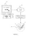
- FIG. 1schematic diagram of a system and method for sharing virtual and augmented reality scenes between users and viewers in accordance with preferred embodiments of the present invention.
- FIGS. 4A to 4Mare schematic representations of a VAR scene being adjusted on a mobile device in accordance with the system and method of the preferred embodiments.
- FIG. 5is a schematic diagram of a system and method for sharing virtual and augmented reality scenes between users and viewers in accordance with variations of the preferred embodiments.
- FIG. 6is a flowchart depicting a method of sharing virtual and augmented reality scenes between users and viewers in accordance with a preferred embodiment of the present invention.
- FIG. 7is a flowchart depicting a method of sharing virtual and augmented reality scenes between users and viewers in accordance with a variation of the preferred embodiment of the present invention.
- FIG. 8is a flowchart depicting a method of sharing virtual and augmented reality scenes between users and viewers in accordance with another variation of the preferred embodiment of the present invention.
- FIG. 10is a flowchart depicting a method of sharing virtual and augmented reality scenes between users and viewers in accordance with another preferred embodiment of the present invention.
- FIG. 11is a flowchart depicting a method of sharing virtual and augmented reality scenes between users and viewers in accordance with another variation of the preferred embodiment of the present invention.
- FIG. 13is a flowchart depicting a method of sharing virtual and augmented reality scenes between users and viewers in accordance with another variation of the preferred embodiment of the present invention.
- the user mobile device 14 and the viewer mobile device 14are substantially similar.
- One or both of the user mobile device 14 and the viewer mobile device 14can include one or more cameras (front/rear), an accelerometer, a gyroscope, a MEMS gyroscope, a magnetometer, a pedometer, a proximity sensor, an infrared sensor, an ultrasound sensor, a global position satellite transceiver, WiFi transceiver, mobile telephone components, and/or any suitable combination thereof for calculating a projection matrix and/or the associated Euler angles.
- orientation and/or position informationcan be gathered in any suitable fashion, including device Application Programming Interfaces (API) or through any suitable API exposing device information, e.g., using HTML5 to expose device information including orientation/location.
- APIApplication Programming Interfaces
- HTML5HyperText Markup Language
- the (user and/or viewer mobile) device 14 of the preferred embodimentcan include a display 40 , an orientation module 50 including a real orientation module and a user orientation module, a location module 60 , a camera 90 oriented in substantially the same direction as the display 40 , and a processor 70 connected to each of the display, orientation module 50 , location module 60 , and camera 90 .
- the device 14 of the preferred embodimentpreferably functions to capture and/or present a virtual and/or augmented reality (VAR) scene to a user from the point of view of a nodal point or center thereof, such that it appears to the user that he or she is viewing the world (represented by the VAR scene) through a frame of a window.
- the device 14 of the preferred embodimentcan include any suitable type of mobile computing apparatus such as a smart phone, a personal computer, a laptop computer, a tablet computer, a television/monitor paired with a separate handheld orientation/location apparatus, or any suitable combination thereof.
- the orientation module 50 of the device 14 of the preferred embodimentincludes at least a real orientation portion and a user orientation portion.
- the real orientation portion of the orientation module 50preferably functions to provide a frame of reference for the device 14 as it relates to a world around it, wherein the world around can include real three dimensional space, a virtual reality space, an augmented reality space, or any suitable combination thereof.
- the projection matrixcan preferably include a mathematical representation of an arbitrary orientation of a three-dimensional object (i.e., the device 14 ) having three degrees of freedom relative to a second frame of reference.
- the projection matrixcan include a mathematical representation of the device 14 orientations in terms of its Euler angles (pitch, roll, yaw) in any suitable coordinate system.
- the second frame of referencecan include a three-dimensional external frame of reference (i.e., real space) in which the gravitational force defines baseline directionality for the relevant coordinate system against which the absolute orientation of the device 14 can be measured.
- the device 14will have certain orientations corresponding to real world orientations, such as up and down, and further such that the device 14 can be rolled, pitched, and/or yawed within the external frame of reference.
- the orientation module 50can include a MEMS gyroscope configured to calculate and/or determine a projection matrix indicative of the orientation of the device 14 .
- the MEMS gyroscopecan be integral with the orientation module 50 .
- the MEMS gyroscopecan be integrated into any other suitable portion of the device 14 or maintained as a discrete module of its own.
- the user orientation portion of the orientation module 50preferably functions to provide a frame of reference for the device 14 relative to a point or object in space, including a point or object in real space.
- the user orientationcan include a measurement of a distance and/or rotational value/s of the device relative to a nodal point.
- the nodal pointcan include a user's head such that the user orientation includes a measurement of the relative distance and/or rotational value/s of the device 14 relative to a user's field of view.
- the nodal pointcan include a portion of the user's head, such as for example a point between the user's eyes.
- a suitable satellite position system 82can include for example the Global Positioning System (GPS) constellation of satellites, Galileo, GLONASS, or any other suitable territorial or national satellite positioning system.
- GPSGlobal Positioning System
- the location module 60 of the preferred embodimentcan include a GPS transceiver, although any other type of transceiver for satellite-based location services can be employed in lieu of or in addition to a GPS transceiver.
- the processor 70 of the device 14 of the preferred embodimentfunctions to manage the presentation of the VAR scene to the viewer 12 .
- the processor 14preferably functions to display a scene to the viewer 12 on the display 40 in response to the real orientation and the user orientation.
- the processor 70 of the preferred embodimentcan be configured to process, compute, calculate, determine, and/or create a VAR scene that can be displayed on the device 14 to a viewer 12 , wherein the VAR scene is oriented to mimic the effect of the viewer 12 viewing the VAR scene as if through the frame of the device 12 .
- orienting the scenecan include preparing a VAR scene for display such that the viewable scene matches what the user would view in a real three-dimensional view, that is, such that the displayable scene provides a simulation of real viewable space to the viewer 12 as if the device 14 were a transparent frame.
- the sceneis preferably a VAR scene; therefore it can include one or more virtual and/or augmented reality elements composing, in addition to, and/or in lieu of one or more real elements (buildings, roads, landmarks, and the like, either real or fictitious).
- the scenecan include processed or unprocessed images/videos/multimedia files of one or more displayable scene aspects, including both actual and fictitious elements as noted above.
- the VAR scenecan include a spherical image 20 .
- the portion of the spherical imagei.e., the VAR scene 18
- the portion of the spherical imagethat is displayable by the device 14 corresponds to an overlap between a viewing frustum of the device (i.e., a viewing cone projected from the device) and the imaginary sphere that includes the spherical image 20 .
- the scene 18is preferably a portion of the spherical image 20 , which can include a substantially rectangular display of a concave, convex, or hyperbolic rectangular portion of the sphere of the spherical image 20 .
- the nodal pointis disposed at approximately the origin of the spherical image 20 , such that a viewer 12 has the illusion of being located at the center of a larger sphere or bubble having the VAR scene displayed on its interior.
- the nodal pointcan be disposed at any other suitable vantage point within the spherical image 20 displayable by the device 14 .
- the displayable scenecan include a substantially planar and/or ribbon-like geometry from which the nodal point is distanced in a constant or variable fashion.
- the display of the scene 18can be performed within a 3D or 2D graphics platform such as OpenGL, WebGL, or Direct 3D.
- the display of the scene 18can be performed within a browser environment using one or more of HTML5, CSS3, or any other suitable markup language.
- the geometry of the displayable scenecan be altered and/or varied in response to an automated input and/or in response to a user input.
- adapting the displayable scenecan include at least one of the processor 70 adjusting a virtual zoom of the scene, the processor 70 adjusting a virtual parallax of the scene, the processor 70 adjusting a virtual perspective of the scene, and/or the processor 70 adjusting a virtual origin of the scene.
- adapting the displayable scenecan include any suitable combination of the foregoing, performed by the processor 70 of the preferred embodiment substantially serially or substantially simultaneously, in response to a timing of any determined changes in one or both of the real orientation or the user orientation.
- the processoris further configured to adjust a virtual zoom of the scene 18 in response to a change in a linear distance 16 between the device 14 and the nodal point 12 .
- the processor 70 of the preferred embodimentcan be configured to alter a size of an aspect 22 of the scene 18 in response to an increase/decease in the linear distance 16 between the device 14 and the nodal point 12 , i.e., the user's head.
- the device 14can be configured to measure a distance 16 between the device 14 and the nodal point 12 , which can include for example using a front facing camera 90 to measure the relative size of the nodal point 12 in order to calculate the distance 16 .
- the adjustment of the virtual zoomcan be proportional to a real zoom (i.e., a real relative sizing) of the nodal point 12 as captured by the device camera 90 .
- a real zoomi.e., a real relative sizing
- the size of the user's headwill appear to increase/decrease, and the adjustment in the zoom can be linearly and/or non-linearly proportional to the resultant increase/decrease imaged by the camera 90 .
- the distance 16 between the nodal point 12 and the device 14can be measured and/or inferred from any other suitable sensor and/or metric, including at least those usable by the device 14 in determining the projection matrix as described above, including for example one or more cameras 90 (front/rear), an accelerometer, a gyroscope, a MEMS gyroscope, a magnetometer, a pedometer, a proximity sensor, an infrared sensor, an ultrasound sensor, and/or any module, portion, or component of the orientation module 50 .
- any other suitable sensor and/or metricincluding at least those usable by the device 14 in determining the projection matrix as described above, including for example one or more cameras 90 (front/rear), an accelerometer, a gyroscope, a MEMS gyroscope, a magnetometer, a pedometer, a proximity sensor, an infrared sensor, an ultrasound sensor, and/or any module, portion, or component of the orientation module 50 .
- the processor 70 of the device of the preferred embodimentcan be further configured to adjust a virtual parallax of the scene 18 in response to a change in a translational distance between the device 14 and the nodal point 12 .
- FIG. 4Fmovement of the device 14 relative to the nodal point 12 in a direction substantially perpendicular to imaginary line 24 can be interpreted by the processor 70 of the preferred embodiment as a request and/or input to move one or more aspects 22 of the scene 18 in a corresponding fashion.
- the scenecan include a foreground aspect 22 that is movable by the processor 70 relative to a background aspect 30 .
- the processor 70can be configured to identify one or more foreground aspects 22 and/or background aspects 30 of the displayable scene 18 .
- the translational distance between the nodal point 12 and the device 14can be measured and/or inferred from any other suitable sensor and/or metric, including at least those usable by the device 14 in determining the projection matrix as described below, including for example one or more cameras 90 (front/rear), an accelerometer, a gyroscope, a MEMS gyroscope, a magnetometer, a pedometer, a proximity sensor, an infrared sensor, an ultrasound sensor, and/or any module, portion, or component of the orientation module 50 .
- any other suitable sensor and/or metricincluding at least those usable by the device 14 in determining the projection matrix as described below, including for example one or more cameras 90 (front/rear), an accelerometer, a gyroscope, a MEMS gyroscope, a magnetometer, a pedometer, a proximity sensor, an infrared sensor, an ultrasound sensor, and/or any module, portion, or component of the orientation module 50 .
- the translational distanceis computed by the processor 70 as a function of both the size of the nodal point 12 (from the front facing camera 90 ) and a detection of a planar translation of the device 14 in a direction substantially orthogonal to the direction of the camera 90 , thus indicating a translational movement without any corrective rotation.
- one or more of the aforementioned sensorscan determine that the device 14 is moved in a direction substantially orthogonal to the camera direction 90 (along imaginary line 24 in FIGS. 4E and 4F ), while also determining that there is no rotation of the device 14 about an axis (i.e., axis 28 shown in FIG. 4J ) that would direct the camera 90 radially inwards towards the nodal point 12 .
- the processor 70 of the device 14 of the preferred embodimentcan process the combination of signals indicative of such a movement as a translational shift of the device 14 relative to the nodal point 12 and adapt a virtual parallax of the viewable scene accordingly.
- adjustment of the virtual perspective of the sceneis related in part to a distance between one end of the device and the nodal point and a distance between the other end of the device and the nodal point 12 .
- rotation of the device 14 about axis 28brings one side of the device 14 closer to the nodal point 12 than the other side, while leaving the top and bottom of the device 14 relatively equidistant from the nodal point 12 .
- the processor 70 of the preferred embodimentcan adjust the virtual perspective of each aspect 22 , 26 of the scene 18 in response to at least its position in the scene 18 , the degree of rotation of the device 14 relative to the nodal point 12 , the relative depth (foreground/background) of the aspect 22 , 26 , and/or any other suitable metric or visual cue.
- lines that are parallel in the scene 18 when the device 14 is directed at the nodal point 12 shown in FIG. 4Iwill converge in some other direction in the display as shown in FIG. 4K as the device 14 is rotated as shown in FIG. 4J .
- the processor 70can be configured to reorient, reshape, resize, and/or translate one or more aspects of the displayable scene 18 in response to the detection of actual movement of the nodal point 12 .
- the nodal pointcan include an arbitrary point in real or fictitious space relative to which the scenes 18 described herein are displayable. Accordingly, any movement of the real or fictitious nodal point 12 preferably results in a corresponding adjustment of the displayable scene 18 by the processor 70 .
- the nodal point 12can include a user's head or any suitable portion thereof.
- one of more portions or modules of the orientation module 50can detect movement of the nodal point 12 in real space, which movements can be used by the processor 70 creating the corresponding adjustments in the displayable scene 18 .
- the real position of the nodal point 12can preferably be determined using any suitable combination of devices, including for example one or more cameras (front/rear), an accelerometer, a gyroscope, a MEMS gyroscope, a magnetometer, a pedometer, a proximity sensor, an infrared sensor, an ultrasound sensor and/or any module, portion, or component of the orientation module 50 .
- a user 12can wear a pedometer in communication with the device such that when the user walks through real space, such movement of the user/nodal point 12 is translated into movement in the VAR space, resulting in a corresponding adjustment to the displayable scene 18 .
- the location module 60 of the device 14 of the preferred embodimentcan determine a position and/or motion of the device 14 in response to a global positioning signal associated with the device 14 .
- real and/or or simulated movement of the user/nodal point 12 in spacecan result in the adjustment of the location of the origin/center/viewing point of the displayable scene 18 .
- the processor 70can be further configured to display a floating-point exposure of the displayable scene in order to minimize lighting irregularities.
- the displayable scene 18can be any suitable geometry, including for example a spherical image 20 disposed substantially symmetrically about a nodal point 12 as shown in FIG. 3 . Displaying a floating-point exposure preferably functions to allow the user to view/experience the full dynamic range of the image without having to artificially adjust the dynamic range of the image.
- the processor 70 of the preferred embodimentis configured to globally adjust the dynamic range of the image such that a portion of the image in the center of the display is within the dynamic range of the device.
- comparable high dynamic range (HDR) imagesappear unnatural because they attempt to confine a large image range into a smaller display range through tone mapping, which is not how the image is naturally captured by a digital camera.
- the processor 70preserves the natural range of the image 20 by adjusting the range of the image 20 to always fit around (either symmetrically or asymmetrically) the portion of the image 18 viewable in the approximate center of the device's display 40 .
- the device 14 of the preferred embodimentcan readily adjust one or more aspects of the displayable scene 18 in response to any number of potential inputs relating to the orientation of the device 14 and/or the nodal point 12 .
- the device 14 of the preferred embodimentcan further be configured to adjust a floating point exposure of the displayable scene 18 in response to any changes in the displayable scene 18 , such as for example adjustments in the virtual zoom, virtual parallax, virtual perspective, and/or virtual origin described in detail above.
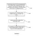
- a method of the first preferred embodimentcan include capturing a virtual and/or augmented reality (VAR) scene with a user mobile device at a location of interest, wherein the VAR scene can include visual data and orientation that can include a real orientation of the user mobile device relative to a projection matrix in block S 600 .
- the first preferred methodcan further include correlating the visual data and the orientation data at the user mobile device in block S 602 , compressing at least the visual data at the user mobile device to generate a processed VAR scene in block S 604 , and transmitting the processed VAR scene to a server in block S 606 .
- VARvirtual and/or augmented reality
- the first preferred methodcan function to assist a user in the capture, processing, and transmission of a user-generated VAR scene to a remote server that can be configured for storage and distribution of the VAR scene to one or more viewers.
- the first preferred methodcan further functions to transform a VAR scene captured by a particular user device into an accessible media file that can be experienced by a number of viewers on any number and type of different viewer devices.
- the VAR scenecan include any number of still and/or video images in any other suitable format, such as planar, ribbon-like, hemispherical, or any combination thereof.
- a usercan preferably be instructed and/or prompted on a suitable manner or means to acquire the VAR scene, including any systems or methods disclosed in the inventors' co-pending patent application Ser. No. 13/302,977 entitled “System and Method for Acquiring Virtual and Augmented Reality Scenes by a User,” filed on 22 Nov. 2011 and assignable to the assignee of the present application.
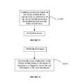
- block S 600can include providing a user with a predetermined pattern for image acquisition with the user mobile device in block and in response to a user input, acquiring at least one image at a location of interest.
- the first preferred methodcan further include in response to the acquisition of at least one image, providing the user with feedback to ensure a complete acquisition of the virtual or augmented reality (VAR) scene.
- VARvirtual or augmented reality
- the first preferred methodfunctions to reduce provide for a uniform, simple, and comprehensive manner in which one or more users can collect image data about their respective surrounding environments.
- the first preferred methodfurther functions to create uniformly accessible VAR scenes, which can be retrieved from one or more users and provided to one or more viewers through network access to a remote server as described below.
- the images acquiredcan be either two-dimensional or three-dimensional images, and they can be either still photographs or one or more frames of a video sequence.
- Enabling capture of spatial imagery by common mobile devicespreferably further functions to enable widespread, crowd-generated, spatially assigned image data. Since untrained users are expected to capture the images, the first preferred method preferably further functions to unobtrusively guide the capture process so that novice photographers will be able to acquire usable quality VAR scenes.
- One preferred variation of the methodutilizes game play mechanics to encourage proper capture of scene imagery.
- the game play mechanicspreferably provide a task-based challenge for the user with device orientation as a central control mechanic. In the background of a game-like interaction, the game preferably results in the user properly orienting the user mobile device for the capture of a scene. Other non-game like interactions can alternatively be used.
- a useracquires images by directing the user mobile device outward as shown in FIG. 1 and systematically spins and directs the camera at particular orientations to acquire all desired visual data for the VAR scene.
- an image of a spherical spaceis preferably created to simulate the world viewable in any direction from the perspective of the user.
- a preferred predetermined pattern for visual data acquisitiondoes not contain undesirable “holes” or voids in the image data.
- the preferred predetermined patterncan be used to form a spatial image scene that can be described as a surface in the shape of a sphere, plane, cylinder, planar path, curved plane, or any suitable surface.
- the predetermined patternpreferably guides the user to move the image capture device in a way that collects image data from the whole world around the user.
- the poles of a sphere or other singularitiescan be special conditions that the predetermined pattern includes.
- the predetermined patternif a user is capturing a plane of image data while walking, the predetermined pattern preferably ensures that a full plane worth of image data with no holes is captured.
- the preferred predetermined patterncan include a programmatically determined pattern that is subject to user override (i.e., through the user actuating the user interface as desired).
- some or all aspects of the preferred predetermined patterncan be compulsory (i.e., through a feedback mechanism of the type described below) to ensure proper acquisition of the image/s.
- capturing a VAR scenecan include acquiring at least one image in a floating-point format to ensure full dynamic spectrum of the virtual or augmented reality scene.
- the VAR scenecan be any suitable geometry, including for example a spherical image disposed substantially symmetrically about a nodal point.
- Acquisition of the VAR visual data in a floating-point exposurepreferably functions to allow the user to view/experience the full dynamic range of the image without having to artificially adjust the dynamic range of the images/scene.
- the first preferred methodglobally adjusts the dynamic range of each image as it is acquired such that a portion of the image in the center of the display is within the dynamic range of the device.
- the first preferred methodpreserves the natural range of the image by adjusting the range of the image to always fit around (either symmetrically or asymmetrically) the portion of the image viewable in an approximate center a display on which it is to be viewed.
- the acquired imagecan include for example a video, a series of still photographs, or any suitable combination thereof.
- the first preferred methodcan further include adjusting the floating point exposure of the acquired images in response to any changes in the sequence of images that make up the VAR scene, such as for example adjustments in the lighting as a user progresses through a series of still images.
- Block S 602preferably functions to pair one or more aspects of the visual data with one or more aspects of the orientation data such that each of the visual data and the orientation data can be disassembled and reassembled according to the proper location and/or orientation of the user mobile device at the time the VAR scene was captured.
- the user mobile devicewill have a substantially unique orientation for each discrete image. Accordingly, each discrete image of the visual data can preferably be correlated with the orientation data of the user mobile device associated with the capture of the discrete image.
- correlation of the visual data and the orientation datacan include merging the visual data and the orientation data into a single media file.
- correlation of the visual data and the orientation datacan include discrete pairings of still images and/or video frames with discrete selections of data representing the orientation of the user mobile device.
- the first preferred methodcan further include block S 604 , which recites compressing at least the visual data at the user mobile device to generate a processed VAR scene.
- Block S 604preferably functions to minimize, streamline, and/or optimize a file size of at least the visual data for ease of transmission to the server.
- block S 604can further include compressing the orientation data with the visual data and/or a combination of the orientation data and the visual data.
- block S 604can be substantially and/or selectively omitted from performance of the first preferred method in response to one or more external conditions, including for example a file size, a relative increase/decrease in available bandwidth, any requirements as to data fidelity, processing speeds, or any other suitable network, hardware, and/or user-defined condition.
- compression of the visual datacan include down-sampling one or more still images and/or video frames.
- the down-sampled visual datacan be fit onto a single large texture, which in turn can be rendered as a collection of individual frames/images placed tangentially on an imaginary sphere with corresponding orientation data for each portion of the visual data.
- approximately two hundred lower resolution imagescan be fit into a 2048 ⁇ 2048 pixel texture.
- the processed VARcan include the visual data, orientation data, and/or audio data storable and/or transmittable as separate discrete data files with association or correlation through positioning, clock/timing, and/or indexing parameters.
- the foregoing image processingis optimized for performance on a user mobile device in response to its processing capabilities and the speed and/or reliability of a connection with the server.
- the first preferred methodcan include block S 606 , which recites transmitting the processed VAR scene to a server.
- Block S 606preferably functions to upload, transfer, distribute, and/or transmit the processed VAR scene data from the user mobile device to a remote server while ensuring the fidelity and completeness of the processed VAR scene received at the server.
- the processed VAR scene datacan be relatively large data file for transmission from a mobile device, particularly over a wireless or cellular network.
- an initial requeste.g., an AJAX request
- the position of the VAR scenecan be included in the initial request.
- Such informationcan optionally be published to a social stream or website prior to completing upload of the processed VAR scene.
- Processed VAR scene informationcan alternatively be published after successful uploading, processing on the system server, or at any suitable point.
- the processed VAR sceneis preferably uploaded in response to successful receipt of the initial request by the server.
- the visual data, a preview image, the orientation data, and/or any audio datacan preferably be uploaded asynchronously.
- UUIDuniversally unique identifier
- a hash of the pathname of the visual data fileswhich preferably functions to alleviate concerns of reserving space for the processed VAR scene before uploading and further enables data to be uploaded out of order.
- any suitable uploading proceduremay alternatively be used.
- another variation of the first preferred methodcan include block S 700 , which recites creating a projection matrix representing an orientation of the user mobile device in a three-dimensional external frame of reference.
- Block S 700preferably functions to coordinate the captured and displayable scene with a physical orientation of the user mobile device as established by and/or relative to a user.
- the projection matrixpreferably includes a mathematical representation of an arbitrary orientation of a three-dimensional object having three degrees of freedom relative to the external frame of reference.
- the external frame of referencecan include a three-dimensional external frame of reference (i.e., real space) in which the gravitational force defines baseline directionality for the relevant coordinate system against which the absolute orientation of the user mobile device can be measured.
- the projection matrixcan include a mathematical representation of the user mobile device's orientation in terms of its Euler angles (pitch, roll, yaw) in any suitable coordinate system.
- the user mobile devicecan include one or more cameras (front/rear), an accelerometer, a gyroscope, a MEMS gyroscope, a magnetometer, a pedometer, a proximity sensor, an infrared sensor, an ultrasound sensor, a global position satellite transceiver, WiFi transceiver, mobile telephone components, and/or any suitable combination thereof for calculating the projection matrix and/or the associated Euler angles.
- Orientation and/or position informationcan be gathered in any suitable fashion, including device Application Programming Interfaces (API) or through any suitable API exposing device information, e.g., using HTML5 to expose device information including orientation/location.
- APIApplication Programming Interfaces
- Block S 900preferably functions to locally maintain the visual data, the orientation data, and/or the audio data that compose the VAR scene within an integrated or local memory storage component of the user mobile device.
- the VAR scenecan be stored in one or both of a processed or unprocessed format.
- the VAR scenecan be locally stored on the user mobile device for a predetermined time period, which can include for example until the user erases the VAR scene and/or underlying data, until the processed VAR scene is successfully transmitted to the server, and/or until the local memory of the user mobile device dictates removal or some or all of the VAR scene data.
- the VAR scenecan be locally stored until receipt of a successful transmission communication from the server, indicating that the entire VAR scene is captured and stored remotely.
- block S 900can include storing the VAR scene and/or VAR scene metadata indefinitely.
- at least the VAR scene metadatacan remain locally stored on the user mobile device so that the user can readily identify, retrieve, view, and/or interact with his or her VAR scenes on the server by comparing and/or matching the VAR scene metadata stored on the user mobile device and the server.
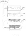
- a second method of the preferred embodimentcan include receiving at a server a VAR scene generated by a user mobile device, wherein the VAR scene includes visual data and orientation data including a real orientation of the user mobile device relative to a projection matrix in block S 1000 .
- the second preferred methodcan further include compositing the visual data and the orientation data into a viewable VAR scene in block S 1002 , locally storing the viewable VAR scene at the server in block S 1004 , and in response to a request received at the server, distributing the processed VAR scene to a viewer mobile device in block S 1006 .
- the second preferred methodfunctions to receive, create, host, and/or distribute high fidelity VAR scenes that are received from one or more users and distributed to one or more viewers.
- a server usable in the second method of the preferred embodimentcan include one or more networked computers, servers, server clusters, databases, data centers, routers, and/or memory storage devices as well as any suitable combination or sub-combination thereof.
- the second preferred methodincludes block S 1000 , which recites receiving at a server a VAR scene generated by a user mobile device, wherein the VAR scene includes visual data and orientation data including a real orientation of the user mobile device relative to a projection matrix.
- Block S 1000preferably functions to receive a processed or unprocessed VAR scene from at least one user mobile device for subsequent processing and distribution to one or more viewers.
- the VAR scenecan include visual data, orientation data, and/or audio data.
- Suitable visual datacan include for example one or more still images arranged in any suitable fashion, such as a substantially spherical series or collection of images.
- Visual datacan alternatively or additionally include one or more video elements such as spherical video frames.
- the orientation datapreferably includes sensor data derived by the user mobile device, such as for example data received from a gyroscope, a MEMS gyroscope, an accelerometer, a magnetometer, a GPS, an altitude sensor, or any suitable combination thereof.
- sensor dataderived by the user mobile device, such as for example data received from a gyroscope, a MEMS gyroscope, an accelerometer, a magnetometer, a GPS, an altitude sensor, or any suitable combination thereof.
- any one or more sensorscan be integrated into the user mobile device or disintegrated or discrete from the user mobile device.
- the VAR scene datacan be received through any available communication means, including wireless or wired communications, and/or through any intermediary systems or devices, such as a user's secondary mobile device or desktop computer.
- the second preferred methodfurther includes block S 1002 , which recites compositing the visual data and the orientation data into a viewable VAR scene.
- Block S 1002preferably functions to perform intermediary processing of the VAR scene between capture by the user mobile device and viewing on the viewer device.
- block S 1002can include aligning any still images and/or video frames into to substantially seamless unitary image when viewed in the VAR scene format, e.g., a spherical image/video.
- compositing the visual data and the orientation datacan further include associating one or more projection matrix parameters with the VAR scene.
- block S 1002can function to properly correlate and/or pair the perspective of the VAR scene with a matching orientation of a device projection matrix (such as a user mobile device or a viewer mobile device).
- block S 1002can include additional image processing such as image quality matching between images in the same VAR scene.
- the serverperforms the compositing through a command line tool run on a separate thread.
- the servercan be configured with substantial processing resources and ample time, more processing of the VAR scene components can occur in block S 1002 as compared to those performed by a mobile device, which has a greater breadth of use and relatively limited processing power.
- the server environmentis more likely to be subject to the quality control and quality assurance efforts of the system developer, thus resulting in greater fidelity and consistency of the viewable VAR scenes processed and distributable to the one or more viewers.
- the second preferred methodcan additionally include block S 1004 , which recites locally storing the viewable VAR scene at the server.
- Block S 1004preferably functions to maintain the VAR scene, the viewable VAR scene, and/or any associated VAR scene metadata in a readily accessible local and/or remote memory component of the server for access and/or distribution to one or more viewers.
- local storage of the viewable VAR scenecan include storage of a compiled media file that contains tracks of the all of the orientation data, visual data, and/or audio data.
- each of the orientation data, visual data, and/or audio datacan be separately stored and indexed for retrieval and viewing by a viewer.
- the viewable VAR scenecan be stored in compressed or non-compressed formats, and can include sample images, sample audio, sample video, or other readily displayable thumbnail icons that permit browsing of the entire viewable VAR scene database by one or more viewers.
- the viewable VAR scenecan be locally stored and indexed by one or more of the following: VAR location, VAR author, VAR augmented content, VAR keyword/s, and/or VAR user account.
- the servercan be configured to locally store viewable VAR scenes by the location of the VAR scene (as determined by the location data associated with the received VAR scene), such that a viewer can search for viewable VAR scenes according to the location at which the viewer is interested in viewing the VAR scene, i.e., a particular intersection, landmark, street, storefront, building interior, and the like.
- the second preferred methodcan further include block S 1006 , which recites in response to a request received at the server, distributing the viewable VAR scene to a viewer mobile device.
- Block S 1006preferably functions to distribute, either directly or indirectly, the viewable VAR scene to a viewer mobile device.
- the viewer mobile devicecan include one or more cameras (front/rear), an accelerometer, a gyroscope, a MEMS gyroscope, a magnetometer, a pedometer, a proximity sensor, an infrared sensor, an ultrasound sensor, a global position satellite transceiver, WiFi transceiver, mobile telephone components, and/or any suitable combination thereof for calculating a projection matrix and/or the associated Euler angles.
- orientation and/or position informationcan be gathered in any suitable fashion, including device Application Programming Interfaces (API) or through any suitable API exposing device information, e.g., using HTML5 to expose device information including orientation/location.
- APIApplication Programming Interfaces
- the request made of the serveris from the viewer mobile device.
- a viewer browsing published VAR scenes stored on the servercan select a scene through a browser link or application link, at which time the request can be transmitted to the server through a Wi-Fi, wired Internet, cellular network, or any other suitable communication channel.
- the servercan direct the viewable VAR scene to the application and/or browser for viewing on the viewer mobile device.
- one variation of the second preferred methodcan include block S 1100 , which recites associating a first viewer device with the viewer mobile device.
- Block S 1100preferably functions to permit a viewer to browse and/or select a viewable VAR scene on a first viewer device (i.e., a non-ideal viewing device) but have the server transmit the viewable VAR scene to the viewer mobile device (an ideal viewing device).
- block S 1100permits a user to select the VAR scene on a first viewer device 106 (shown as a desktop computer), which request is directed to the system server 102 , which in turn pushes the viewable VAR scene to a viewer mobile device 14 .
- Example first viewer devicescan include non-ideal devices that are immobile or otherwise difficult to physically maneuver to view the entire VAR scene, such as for example desktop computers and Internet capable televisions.
- block S 1100can include creating a viewer account on the server that is accessible from the first viewer device and the viewer mobile device, thereby associating the user with a cookie and/or a username/password combination.
- the vieweraccesses his or her account on the viewer mobile device (e.g., through a dedicated application on a smartphone or tablet computer) and creates a token such as a device token or push token associated with the username.
- the serverwhen the logged in viewer selects a VAR scene on the first viewer device, the server preferably directly pushes the viewable VAR scene to the viewer mobile device. Additionally, the server can provide a listing or index of all available associated devices for any user account, which can be accessible through any suitable viewer device. If the viewer has more than one device associated with his or her user account, he or she can instruct the server to push the viewable VAR scene to a selected device, which need not be an ideal viewing device.
- the viewable VAR sceneincludes VAR scene data processed by the server.
- the VAR scene datapreferably includes six sides of a cube as images or alternatively videos, an audio file, and a list of orientations. Other aspects of the VAR scene may also be sent such as annotations or additional elements included in the VAR scene.
- the datais preferably communicated through JavaScript object notation (JSON), but any suitable object notation or data structure may alternatively be used.
- JSONJavaScript object notation
- a third method of the preferred embodimentcan include block S 1200 , which recites from a viewer device, requesting a VAR scene from a server, wherein the VAR scene includes visual data and orientation data including a real orientation of a mobile device relative to a projection matrix.
- the third preferred methodcan also include receiving the VAR scene at a viewer mobile device in block S 1202 , determining a real orientation of the viewer mobile device relative to a projection matrix in block S 1204 , and determining a user orientation of the viewer mobile device relative to a nodal point in block S 1206 .
- the third preferred methodcan also include orienting a scene displayable on the viewer mobile device to the viewer in response to the real orientation and the user orientation in block S 1208 and displaying the VAR scene on the viewer mobile device in block S 1210 .
- the third preferred methodfunctions to retrieve, receive, render, and/or display a server-hosted VAR scene to a viewer on his or her viewer mobile device.
- the third preferred embodimentincludes block S 1200 , which recites from a viewer device, requesting a VAR scene from a server.
- the VAR sceneincludes visual data, orientation data, and/or audio data
- the orientation datapreferably includes a real orientation of a mobile device relative to a projection matrix.
- the real orientation of a mobile device relative to a projection matrixcan include any suitable type of device, including the user mobile device that created the VAR scene, the viewer mobile device on which the VAR scene is to be viewed, or an archetypal mobile device that is independent of the type of device on which the VAR scene is captured/viewed.
- the viewer deviceis one of a first viewer device or a mobile viewer device.
- suitable visual datacan include for example one or more still images arranged in any suitable fashion, such as a substantially spherical series or collection of images.
- Visual datacan alternatively or additionally include one or more video elements such as spherical video frames.
- the orientation datapreferably includes sensor data derived by the user mobile device and usable by the viewer mobile device, such as for example data received from a gyroscope, a MEMS gyroscope, an accelerometer, a magnetometer, a GPS, an altitude sensor, or any suitable combination thereof. Any one or more sensors can be integrated into the viewer mobile device in order to assist in viewing the entire VAR scene.
- the VAR scene datacan be received at the viewer mobile device through any available communication means, including wireless or wired communications, and/or through any intermediary systems or devices, such as a user's secondary mobile device or desktop computer.
- the third preferred methodcan include block S 1202 , which recites receiving the VAR scene at a viewer mobile device.
- Block S 1202preferably functions to direct the VAR scene to the viewer mobile device in response to a request from the viewer mobile device, the first viewer device, or any other device/s associated with the viewer.
- the VAR scenecan be requested from the server on a first viewer device (a non-ideal viewing device) and received and/or viewed on an associated viewer mobile device.
- the VAR sceneis processed by the server prior to receipt by the viewer mobile device. Suitable processing can include at least those functions described above with reference to FIG. 10 .
- the VAR scenecan be received at the viewer mobile device in a raw or partially processed form in such a manner that the viewer mobile device can perform any needed or desired processing of the VAR scene locally.
- the VAR scenecan be retrieved from the server in processed, partially processed, and/or raw formats based upon viewer selection, network speeds, viewer mobile device processing capacity, and/or any other suitable parameter.
- the third preferred methodcan include block S 1204 , which recites determining a real orientation of the viewer mobile device relative to a projection matrix.
- Block S 1204functions to provide a frame of reference for the viewer mobile device as it relates to a world around it, wherein the world around can include real three dimensional space, a virtual reality space, an augmented reality space, or any suitable combination thereof.
- the projection matrixcan include a mathematical representation of an arbitrary orientation of a three-dimensional object having three degrees of freedom relative to a second frame of reference.
- the projection matrixcan include a mathematical representation of a viewer mobile device's orientation in terms of its Euler angles (pitch, roll, yaw) in any suitable coordinate system.
- the second frame of referencecan include a three-dimensional external frame of reference (i.e., real space) in which the gravitational force defines baseline directionality for the relevant coordinate system against which the absolute orientation of the viewer mobile device can be measured.
- the real orientation of the viewer mobile devicecan include an orientation of the viewer mobile device relative to the second frame of reference, which as noted above can include a real three-dimensional frame of reference.
- the viewer mobile devicewill have certain orientations corresponding to real world orientations, such as up and down, and further such that the viewer mobile device can be rolled, pitched, and/or yawed within the external frame of reference.
- the third preferred methodfurther includes block S 1206 , which recites determining a user orientation of the viewer mobile device relative to a nodal point.
- Block S 1206preferably functions to provide a frame of reference for the viewer mobile device relative to a point or object in space, including a point or object in real space.
- the user orientationcan include a measurement of a distance and/or rotational value/s of the viewer mobile device relative to the nodal point.
- the nodal pointcan include a viewer's head such that the user orientation includes a measurement of the relative distance and/or rotational value/s of the viewer mobile device relative to a viewer's field of view.
- the nodal pointcan include a portion of the viewer's head, such as for example a point between the viewer's eyes.
- the nodal pointcan include any other suitable point in space, including for example any arbitrary point such as an inanimate object, a group of users, a landmark, a location, a waypoint, a predetermined coordinate, and the like.
- the user orientationfunctions to create a viewing relationship between a viewer (optionally located at the nodal point) and the viewer mobile device, such that a change in user orientation can cause a consummate change in viewable content consistent with the viewer's VAR interaction, i.e., such that the viewer's view through the frame of the viewer mobile device will be adjusted consistent with the viewer's orientation relative to the frame of the viewer mobile device.
- the third preferred methodcan also include block S 1208 , which recites orienting the VAR scene displayable on the viewer mobile device to a user in response to the real orientation and the user orientation.
- Block S 1208preferably functions to process, compute, calculate, determine, and/or create a VAR scene that can be displayed on the viewer mobile device to a user, wherein the VAR scene is oriented to mimic the effect of the viewer viewing the VAR scene as if through the frame of the viewer mobile device.
- the third preferred methodcan also include block S 1210 , which recites displaying the scene on the viewer mobile device.
- Block S 1210preferably functions to render, present, project, image, and/or display viewable content on, in, or by a viewer mobile device of the type described herein.
- the displayable scenecan include a spherical image of a space having virtual and/or augmented reality components.
- the spherical image displayable on the devicecan be substantially symmetrically disposed about the nodal point, i.e. the nodal point is substantially coincident with and/or functions as an origin of a spheroid upon which the image is rendered.
- the external frame of referencecan include a three-dimensional external frame of reference (i.e., real space) in which the gravitational force defines baseline directionality for the relevant coordinate system against which the absolute orientation of the viewer mobile device can be measured.
- the external frame of referencecan include a fictitious external frame of reference, i.e., such as that encountered in a film or novel, whereby any suitable metrics and/or geometries can apply for navigating the device through the pertinent orientations.
- a fictitious external frame of referencecan include a fictitious space station frame of reference, wherein there is little to no gravitational force to provide the baseline directionality noted above.
- the external frame of referencecan be fitted or configured consistently with the other features of the VAR scene.
- block S 1400recites adapting the scene displayable on the viewer mobile device to the user in response to a change in one of the real orientation or the user orientation.
- Block S 1400preferably functions to alter, change, reconfigure, recompute, regenerate, and/or adapt the displayable scene in response to a change in the real orientation or the user orientation.
- block S 1400preferably functions to create a uniform and immersive viewer experience by adapting the displayable scene consistent with movement of the viewer mobile device relative to the projection matrix and/or relative to the nodal point.
- adapting the displayable scenecan include at least one of adjusting a virtual zoom of the scene, adjusting a virtual parallax of the scene, adjusting a virtual perspective of the scene, and/or adjusting a virtual origin of the scene.
- adapting the displayable scenecan include any suitable combination of the foregoing, performed substantially serially or substantially simultaneously, in response to a timing of any determined changes in one or both of the real orientation or the user orientation.
- another variation of the third preferred methodcan include block S 1502 , which recites adjusting a virtual zoom of the scene in response to a change in a linear distance between the device and the nodal point.
- Block S 1502preferably functions to resize one or more displayable aspects of the scene in response to a distance between the device and the nodal point to mimic a change in the viewing distance of the one or more aspects of the scene.
- the nodal pointcan preferably be coincident with a user's head, such that a distance between the device and the nodal point correlates substantially directly with a distance between a user's eyes and the device.
- adjusting a virtual zoomcan function in part to make displayable aspects of the scene relatively larger in response to a decrease in distance between the device and the nodal point; and to make displayable aspects of the scene relatively smaller in response to an increase in distance between the device and the nodal point.
- Another variation of the third preferred methodcan include measuring a distance between the device and the nodal point, which can include for example using a front facing camera to measure the relative size of the nodal point (i.e., the user's head) in order to calculate the distance.
- the adjustment of the virtual zoomcan be proportional to a real zoom (i.e., a real relative sizing) of the nodal point (i.e., the user's head) as captured by the device camera.
- the distance between the nodal point and the devicecan be measured and/or inferred from any other suitable sensor and/or metric, including at least those usable by the device in determining the projection matrix as described below, including for example one or more cameras (front/rear), an accelerometer, a gyroscope, a MEMS gyroscope, a magnetometer, a pedometer, a proximity sensor, an infrared sensor, an ultrasound sensor, and/or any suitable combination thereof.
- Block S 1504recites adjusting a virtual parallax of the scene in response to a change in a translational distance between the device and the nodal point.
- Block S 1504preferably functions to reorient the relative size and/or placement of one or more aspects of the displayable scene in response to a translational movement between the device and the nodal point.
- a translational movementcan include for example a relative movement between the nodal point and the device in or along a direction substantially perpendicular to a line of sight from the nodal point, i.e., substantially tangential to an imaginary circle having the nodal point as its origin.
- the nodal pointcan preferably be coincident with a user's head, such that the translational distance between the device and the nodal point correlates substantially directly with a distance between a user's eyes and the device.
- adjusting a virtual parallaxcan function in part to adjust a positioning of certain displayable aspects of the scene relative to other displayable aspects of the scene.
- adjusting a virtual parallaxpreferably causes one or more foreground aspects of the displayable scene to move relative to one or more background aspects of the displayable scene.
- Another variation of the third preferred methodcan include identifying one or more foreground aspects of the displayable scene and/or identifying one or more background aspects of the displayable scene.
- Another variation of the third preferred methodcan include measuring a translational distance between the device and the nodal point, which can include for example using a front facing camera to measure the relative size and/or location of the nodal point (i.e., the user's head) in order to calculate the translational distance.
- another variation of the third preferred methodcan include block S 1506 , which recites adjusting a virtual perspective of the scene in response to a change in a rotational orientation of the device and the nodal point.
- Block S 1506preferably functions to reorient, reshape, resize, and/or skew one or more aspects of the displayable scene to convey a sense of perspective and/or a non-plan viewing angle of the scene in response to a rotational movement of the device relative to the nodal point.
- adjustment of the virtual perspective of the sceneis related in part to a distance between one end of the device and the nodal point and a distance between the other end of the device and the nodal point.
- aspects of the left/top portion of the sceneshould be adapted to appear relatively closer (i.e., displayable larger) than aspects of the right/bottom portion of the scene.
- adjustment of the aspects of the scene to create the virtual perspectivewill apply both to foreground aspects and background aspects, such that the third preferred method adjusts the virtual perspective of each aspect of the scene in response to at least its position in the scene, the degree of rotation of the device relative to the nodal point, the relative depth (foreground/background) of the aspect, and/or any other suitable metric or visual cue.
- Another variation of the third preferred methodcan include measuring a rotational orientation between the device and the nodal point, which can include for example using a front facing camera to measure the relative position of the nodal point (i.e., the user's head) in order to calculate the rotational orientation.
- the rotational orientation of the nodal point and the devicecan be measured and/or inferred from any other suitable sensor and/or metric, including at least those usable by the device in determining the projection matrix as described below, including for example one or more cameras (front/rear), an accelerometer, a gyroscope, a MEMS gyroscope, a magnetometer, a pedometer, a proximity sensor, an infrared sensor, an ultrasound sensor, and/or any suitable combination thereof.
- the rotational orientationcan be measured by a combination of the position of the nodal point (as detected by the front facing camera) and a detection of a rotation of the device that shifts the direction of the camera relative to the nodal point.
- a front facing cameracan be used to determine a rotation of the device by detecting a movement of the nodal point within the field of view of the camera (indicating that the device/camera is being rotated in an opposite direction). Accordingly, if the nodal point moves to the bottom/right of the camera field of view, then the third preferred method can determine that the device is being rotated in a direction towards the top/left of the camera field of view. In response to such a rotational orientation, the third preferred method preferably mirrors, adjusts, rotates, and/or skews the viewable scene to match the displaced perspective that the device itself views through the front facing camera.
- another variation of the third preferred methodcan include block S 1508 , which recites adjusting a virtual origin of the scene in response to a change in a real position of the nodal point.
- Block S 1508preferably functions to reorient, reshape, resize, and/or translate one or more aspects of the displayable scene in response to the detection of actual movement of the nodal point.
- the nodal pointcan include an arbitrary point in real or fictitious space relative to which the scenes described herein are displayable. Accordingly, any movement of the real or fictitious nodal point preferably results in a corresponding adjustment of the displayable scene.
- the nodal pointcan include a user's head or any suitable portion thereof.
- movement of the user in real spacecan preferably be detected and used for creating the corresponding adjustments in the displayable scene.
- the real position of the nodal pointcan preferably be determined using any suitable combination of devices, including for example one or more cameras (front/rear), an accelerometer, a gyroscope, a MEMS gyroscope, a magnetometer, a pedometer, a proximity sensor, an infrared sensor, and/or an ultrasound sensor.
- a usercan wear a pedometer in communication with the device such that when the user walks through real space, such movement of the user/nodal point is translated into movement in the VAR space, resulting in a corresponding adjustment to the displayable scene.
- Another variation of the third preferred methodcan include determining a position and/or motion of the device in response to location service signal associated with the device.
- Example location service signalscan include global positioning signals and/or transmission or pilot signals transmittable by the device in attempting to connect to an external network, such as a mobile phone or Wi-Fi type wireless network.
- the real movement of the user/nodal point in spacecan result in the adjustment of the location of the origin/center/viewing point of the displayable scene.
- the user and viewer devices 14 and methods of the preferred embodimentcan be embodied and/or implemented at least in part as a machine configured to receive a computer-readable medium storing computer-readable instructions.
- the instructionsare preferably executed by computer-executable components preferably integrated with the user/viewer device 14 and one or more portions of the processor 70 , orientation module 50 and/or location module 60 .
- Other systems and methods of the preferred embodimentcan be embodied and/or implemented at least in part as a machine configured to receive a computer-readable medium storing computer-readable instructions.
- the instructionsare preferably executed by computer-executable components preferably integrated by computer-executable components preferably integrated with a user/viewer device 14 , a server 102 , and/or a first viewer device 106 of the type described above.
- the computer-readable mediumcan be stored on any suitable computer readable media such as RAMs, ROMs, flash memory, EEPROMs, optical devices (CD or DVD), hard drives, floppy drives, or any suitable device.
- the computer-executable componentis preferably a processor but any suitable dedicated hardware device can (alternatively or additionally) execute the instructions.
Landscapes
- Engineering & Computer Science (AREA)
- Multimedia (AREA)
- Signal Processing (AREA)
- General Engineering & Computer Science (AREA)
- Remote Sensing (AREA)
- Business, Economics & Management (AREA)
- Life Sciences & Earth Sciences (AREA)
- Biodiversity & Conservation Biology (AREA)
- Ecology (AREA)
- Emergency Management (AREA)
- Environmental & Geological Engineering (AREA)
- Environmental Sciences (AREA)
- Computer Security & Cryptography (AREA)
- Databases & Information Systems (AREA)
- Library & Information Science (AREA)
- User Interface Of Digital Computer (AREA)
- Processing Or Creating Images (AREA)
Abstract
Description
Claims (20)
Priority Applications (1)
| Application Number | Priority Date | Filing Date | Title |
|---|---|---|---|
| US14/582,017US9271025B2 (en) | 2011-01-10 | 2014-12-23 | System and method for sharing virtual and augmented reality scenes between users and viewers |
Applications Claiming Priority (4)
| Application Number | Priority Date | Filing Date | Title |
|---|---|---|---|
| US201161431196P | 2011-01-10 | 2011-01-10 | |
| US201161448141P | 2011-03-01 | 2011-03-01 | |
| US13/347,273US8953022B2 (en) | 2011-01-10 | 2012-01-10 | System and method for sharing virtual and augmented reality scenes between users and viewers |
| US14/582,017US9271025B2 (en) | 2011-01-10 | 2014-12-23 | System and method for sharing virtual and augmented reality scenes between users and viewers |
Related Parent Applications (1)
| Application Number | Title | Priority Date | Filing Date |
|---|---|---|---|
| US13/347,273ContinuationUS8953022B2 (en) | 2011-01-10 | 2012-01-10 | System and method for sharing virtual and augmented reality scenes between users and viewers |
Publications (2)
| Publication Number | Publication Date |
|---|---|
| US20150113581A1 US20150113581A1 (en) | 2015-04-23 |
| US9271025B2true US9271025B2 (en) | 2016-02-23 |
Family
ID=46877029
Family Applications (2)
| Application Number | Title | Priority Date | Filing Date |
|---|---|---|---|
| US13/347,273Active2032-11-15US8953022B2 (en) | 2011-01-10 | 2012-01-10 | System and method for sharing virtual and augmented reality scenes between users and viewers |
| US14/582,017Active2032-09-16US9271025B2 (en) | 2011-01-10 | 2014-12-23 | System and method for sharing virtual and augmented reality scenes between users and viewers |
Family Applications Before (1)
| Application Number | Title | Priority Date | Filing Date |
|---|---|---|---|
| US13/347,273Active2032-11-15US8953022B2 (en) | 2011-01-10 | 2012-01-10 | System and method for sharing virtual and augmented reality scenes between users and viewers |
Country Status (1)
| Country | Link |
|---|---|
| US (2) | US8953022B2 (en) |
Cited By (6)
| Publication number | Priority date | Publication date | Assignee | Title |
|---|---|---|---|---|
| US20150243085A1 (en)* | 2014-02-21 | 2015-08-27 | Dropbox, Inc. | Techniques for capturing and displaying partial motion in virtual or augmented reality scenes |
| US9723226B2 (en) | 2010-11-24 | 2017-08-01 | Aria Glassworks, Inc. | System and method for acquiring virtual and augmented reality scenes by a user |
| US20170236323A1 (en)* | 2016-02-16 | 2017-08-17 | Samsung Electronics Co., Ltd | Method and apparatus for generating omni media texture mapping metadata |
| US10068383B2 (en) | 2012-10-02 | 2018-09-04 | Dropbox, Inc. | Dynamically displaying multiple virtual and augmented reality views on a single display |
| US20190005738A1 (en)* | 2017-03-03 | 2019-01-03 | Clicked Inc. | Method of playing virtual reality image and program using the same |
| US11367259B2 (en) | 2013-03-14 | 2022-06-21 | Dropbox, Inc. | Method for simulating natural perception in virtual and augmented reality scenes |
Families Citing this family (104)
| Publication number | Priority date | Publication date | Assignee | Title |
|---|---|---|---|---|
| US8907983B2 (en) | 2010-10-07 | 2014-12-09 | Aria Glassworks, Inc. | System and method for transitioning between interface modes in virtual and augmented reality applications |
| US9070219B2 (en) | 2010-11-24 | 2015-06-30 | Aria Glassworks, Inc. | System and method for presenting virtual and augmented reality scenes to a user |
| US9041743B2 (en) | 2010-11-24 | 2015-05-26 | Aria Glassworks, Inc. | System and method for presenting virtual and augmented reality scenes to a user |
| US8953022B2 (en)* | 2011-01-10 | 2015-02-10 | Aria Glassworks, Inc. | System and method for sharing virtual and augmented reality scenes between users and viewers |
| US9118970B2 (en) | 2011-03-02 | 2015-08-25 | Aria Glassworks, Inc. | System and method for embedding and viewing media files within a virtual and augmented reality scene |
| US8638498B2 (en) | 2012-01-04 | 2014-01-28 | David D. Bohn | Eyebox adjustment for interpupillary distance |
| US9726887B2 (en) | 2012-02-15 | 2017-08-08 | Microsoft Technology Licensing, Llc | Imaging structure color conversion |
| US9368546B2 (en) | 2012-02-15 | 2016-06-14 | Microsoft Technology Licensing, Llc | Imaging structure with embedded light sources |
| US9779643B2 (en) | 2012-02-15 | 2017-10-03 | Microsoft Technology Licensing, Llc | Imaging structure emitter configurations |
| US9297996B2 (en) | 2012-02-15 | 2016-03-29 | Microsoft Technology Licensing, Llc | Laser illumination scanning |
| US9578318B2 (en) | 2012-03-14 | 2017-02-21 | Microsoft Technology Licensing, Llc | Imaging structure emitter calibration |
| US11068049B2 (en)* | 2012-03-23 | 2021-07-20 | Microsoft Technology Licensing, Llc | Light guide display and field of view |
| US10191515B2 (en) | 2012-03-28 | 2019-01-29 | Microsoft Technology Licensing, Llc | Mobile device light guide display |
| US9558590B2 (en) | 2012-03-28 | 2017-01-31 | Microsoft Technology Licensing, Llc | Augmented reality light guide display |
| US9717981B2 (en) | 2012-04-05 | 2017-08-01 | Microsoft Technology Licensing, Llc | Augmented reality and physical games |
| US8803916B1 (en)* | 2012-05-03 | 2014-08-12 | Sprint Communications Company L.P. | Methods and systems for an augmented reality service delivery platform |
| US10502876B2 (en) | 2012-05-22 | 2019-12-10 | Microsoft Technology Licensing, Llc | Waveguide optics focus elements |
| US8989535B2 (en) | 2012-06-04 | 2015-03-24 | Microsoft Technology Licensing, Llc | Multiple waveguide imaging structure |
| US8918087B1 (en) | 2012-06-08 | 2014-12-23 | Sprint Communications Company L.P. | Methods and systems for accessing crowd sourced landscape images |
| US9196094B2 (en) | 2012-11-30 | 2015-11-24 | Empire Technology Develoment Llc | Method and apparatus for augmented reality |
| JP2014112302A (en)* | 2012-12-05 | 2014-06-19 | Ricoh Co Ltd | Prescribed area management system, communication method, and program |
| US10192358B2 (en) | 2012-12-20 | 2019-01-29 | Microsoft Technology Licensing, Llc | Auto-stereoscopic augmented reality display |
| KR20140118605A (en)* | 2013-03-29 | 2014-10-08 | 인텔렉추얼디스커버리 주식회사 | Server and method for transmitting augmented reality object |
| KR20140118604A (en)* | 2013-03-29 | 2014-10-08 | 인텔렉추얼디스커버리 주식회사 | Server and method for transmitting augmented reality object to personalized |
| CA2913218C (en) | 2013-05-24 | 2022-09-27 | Awe Company Limited | Systems and methods for a shared mixed reality experience |
| US9858482B2 (en) | 2013-05-28 | 2018-01-02 | Ent. Services Development Corporation Lp | Mobile augmented reality for managing enclosed areas |
| HK1181255A2 (en)* | 2013-07-18 | 2013-11-01 | Spencer Yu Cheong Leung | Monitor system and method for smart device |
| US9596404B2 (en)* | 2013-10-23 | 2017-03-14 | Nokia Technologies Oy | Method and apparatus for generating a media capture request using camera pose information |
| US9185675B2 (en)* | 2013-11-18 | 2015-11-10 | Qualcomm Incorporated | Method and apparatus for classifying a mobile device location |
| US9451051B1 (en) | 2014-02-13 | 2016-09-20 | Sprint Communications Company L.P. | Method and procedure to improve delivery and performance of interactive augmented reality applications over a wireless network |
| US10932103B1 (en)* | 2014-03-21 | 2021-02-23 | Amazon Technologies, Inc. | Determining position of a user relative to a tote |
| US9959675B2 (en) | 2014-06-09 | 2018-05-01 | Microsoft Technology Licensing, Llc | Layout design using locally satisfiable proposals |
| US9934573B2 (en)* | 2014-09-17 | 2018-04-03 | Intel Corporation | Technologies for adjusting a perspective of a captured image for display |
| US9591349B2 (en)* | 2014-12-23 | 2017-03-07 | Intel Corporation | Interactive binocular video display |
| US20160195849A1 (en)* | 2015-01-05 | 2016-07-07 | Intel Corporation | Facilitating interactive floating virtual representations of images at computing devices |
| US10317677B2 (en) | 2015-02-09 | 2019-06-11 | Microsoft Technology Licensing, Llc | Display system |
| US10018844B2 (en) | 2015-02-09 | 2018-07-10 | Microsoft Technology Licensing, Llc | Wearable image display system |
| EP3274676B1 (en)* | 2015-03-23 | 2024-03-06 | The Trustees of Princeton University | Spherical-motion average radiant temperature sensor |
| US10242474B2 (en) | 2015-07-15 | 2019-03-26 | Fyusion, Inc. | Artificially rendering images using viewpoint interpolation and extrapolation |
| US10147211B2 (en) | 2015-07-15 | 2018-12-04 | Fyusion, Inc. | Artificially rendering images using viewpoint interpolation and extrapolation |
| US11095869B2 (en) | 2015-09-22 | 2021-08-17 | Fyusion, Inc. | System and method for generating combined embedded multi-view interactive digital media representations |
| US12261990B2 (en) | 2015-07-15 | 2025-03-25 | Fyusion, Inc. | System and method for generating combined embedded multi-view interactive digital media representations |
| US10222932B2 (en) | 2015-07-15 | 2019-03-05 | Fyusion, Inc. | Virtual reality environment based manipulation of multilayered multi-view interactive digital media representations |
| US11006095B2 (en) | 2015-07-15 | 2021-05-11 | Fyusion, Inc. | Drone based capture of a multi-view interactive digital media |
| US20170084084A1 (en)* | 2015-09-22 | 2017-03-23 | Thrillbox, Inc | Mapping of user interaction within a virtual reality environment |
| US11783864B2 (en) | 2015-09-22 | 2023-10-10 | Fyusion, Inc. | Integration of audio into a multi-view interactive digital media representation |
| US9681111B1 (en) | 2015-10-22 | 2017-06-13 | Gopro, Inc. | Apparatus and methods for embedding metadata into video stream |
| US10033928B1 (en) | 2015-10-29 | 2018-07-24 | Gopro, Inc. | Apparatus and methods for rolling shutter compensation for multi-camera systems |
| US9792709B1 (en) | 2015-11-23 | 2017-10-17 | Gopro, Inc. | Apparatus and methods for image alignment |
| US9973696B1 (en) | 2015-11-23 | 2018-05-15 | Gopro, Inc. | Apparatus and methods for image alignment |
| US9848132B2 (en) | 2015-11-24 | 2017-12-19 | Gopro, Inc. | Multi-camera time synchronization |
| US10593028B2 (en)* | 2015-12-03 | 2020-03-17 | Samsung Electronics Co., Ltd. | Method and apparatus for view-dependent tone mapping of virtual reality images |
| US10147235B2 (en) | 2015-12-10 | 2018-12-04 | Microsoft Technology Licensing, Llc | AR display with adjustable stereo overlap zone |
| US10404938B1 (en) | 2015-12-22 | 2019-09-03 | Steelcase Inc. | Virtual world method and system for affecting mind state |
| US9667859B1 (en) | 2015-12-28 | 2017-05-30 | Gopro, Inc. | Systems and methods for determining preferences for capture settings of an image capturing device |
| WO2017116952A1 (en) | 2015-12-29 | 2017-07-06 | Dolby Laboratories Licensing Corporation | Viewport independent image coding and rendering |
| US9928696B2 (en)* | 2015-12-30 | 2018-03-27 | Immersion Corporation | Externally-activated haptic devices and systems |
| US9922387B1 (en) | 2016-01-19 | 2018-03-20 | Gopro, Inc. | Storage of metadata and images |
| US9967457B1 (en) | 2016-01-22 | 2018-05-08 | Gopro, Inc. | Systems and methods for determining preferences for capture settings of an image capturing device |
| US20170216728A1 (en)* | 2016-01-29 | 2017-08-03 | Twin Harbor Labs Llc | Augmented reality incorporating physical objects |
| US9665098B1 (en) | 2016-02-16 | 2017-05-30 | Gopro, Inc. | Systems and methods for determining preferences for flight control settings of an unmanned aerial vehicle |
| WO2017143289A1 (en)* | 2016-02-17 | 2017-08-24 | Gopro, Inc. | System and method for presenting and viewing a spherical video segment |
| US9602795B1 (en) | 2016-02-22 | 2017-03-21 | Gopro, Inc. | System and method for presenting and viewing a spherical video segment |
| US10181218B1 (en) | 2016-02-17 | 2019-01-15 | Steelcase Inc. | Virtual affordance sales tool |
| US9973746B2 (en) | 2016-02-17 | 2018-05-15 | Gopro, Inc. | System and method for presenting and viewing a spherical video segment |
| US9743060B1 (en) | 2016-02-22 | 2017-08-22 | Gopro, Inc. | System and method for presenting and viewing a spherical video segment |
| US10373381B2 (en) | 2016-03-30 | 2019-08-06 | Microsoft Technology Licensing, Llc | Virtual object manipulation within physical environment |
| GB2551473A (en)* | 2016-04-29 | 2017-12-27 | String Labs Ltd | Augmented media |
| US20170337745A1 (en) | 2016-05-23 | 2017-11-23 | tagSpace Pty Ltd | Fine-grain placement and viewing of virtual objects in wide-area augmented reality environments |
| US10298587B2 (en) | 2016-06-20 | 2019-05-21 | International Business Machines Corporation | Peer-to-peer augmented reality handlers |
| WO2018002882A1 (en)* | 2016-06-30 | 2018-01-04 | Nokia Technologies Oy | Method and apparatus for rotation and switching of video content |
| US10403044B2 (en) | 2016-07-26 | 2019-09-03 | tagSpace Pty Ltd | Telelocation: location sharing for users in augmented and virtual reality environments |
| EP3494447B1 (en) | 2016-08-04 | 2021-05-19 | Reification Inc. | Methods for simultaneous localization and mapping (slam) and related apparatus and systems |
| US10831334B2 (en)* | 2016-08-26 | 2020-11-10 | tagSpace Pty Ltd | Teleportation links for mixed reality environments |
| EP3293703B1 (en) | 2016-09-07 | 2023-03-22 | Airbus Operations GmbH | Virtual window device and method for operating a virtual window device |
| US9934758B1 (en) | 2016-09-21 | 2018-04-03 | Gopro, Inc. | Systems and methods for simulating adaptation of eyes to changes in lighting conditions |
| US10268896B1 (en) | 2016-10-05 | 2019-04-23 | Gopro, Inc. | Systems and methods for determining video highlight based on conveyance positions of video content capture |
| WO2018078535A1 (en)* | 2016-10-25 | 2018-05-03 | Wung Benjamin Ee Pao | Neutral environment recording device |
| US9973792B1 (en) | 2016-10-27 | 2018-05-15 | Gopro, Inc. | Systems and methods for presenting visual information during presentation of a video segment |
| US10182210B1 (en) | 2016-12-15 | 2019-01-15 | Steelcase Inc. | Systems and methods for implementing augmented reality and/or virtual reality |
| US10769797B2 (en)* | 2017-01-05 | 2020-09-08 | Samsung Electronics Co., Ltd. | Virtual reality experience sharing |
| WO2018131813A1 (en) | 2017-01-10 | 2018-07-19 | Samsung Electronics Co., Ltd. | Method and apparatus for generating metadata for 3d images |
| US10437879B2 (en) | 2017-01-18 | 2019-10-08 | Fyusion, Inc. | Visual search using multi-view interactive digital media representations |
| US20180227482A1 (en) | 2017-02-07 | 2018-08-09 | Fyusion, Inc. | Scene-aware selection of filters and effects for visual digital media content |
| US10194101B1 (en) | 2017-02-22 | 2019-01-29 | Gopro, Inc. | Systems and methods for rolling shutter compensation using iterative process |
| CN108513096B (en)* | 2017-02-27 | 2021-09-14 | 中国移动通信有限公司研究院 | Information transmission method, proxy server, terminal device and content server |
| US11093927B2 (en)* | 2017-03-29 | 2021-08-17 | International Business Machines Corporation | Sensory data collection in an augmented reality system |
| US10187607B1 (en) | 2017-04-04 | 2019-01-22 | Gopro, Inc. | Systems and methods for using a variable capture frame rate for video capture |
| US10547704B2 (en) | 2017-04-06 | 2020-01-28 | Sony Interactive Entertainment Inc. | Predictive bitrate selection for 360 video streaming |
| US10313651B2 (en) | 2017-05-22 | 2019-06-04 | Fyusion, Inc. | Snapshots at predefined intervals or angles |
| US11069147B2 (en) | 2017-06-26 | 2021-07-20 | Fyusion, Inc. | Modification of multi-view interactive digital media representation |
| CN109996060B (en)* | 2017-12-30 | 2021-09-03 | 深圳多哚新技术有限责任公司 | Virtual reality cinema system and information processing method |
| CN108197325A (en)* | 2018-02-06 | 2018-06-22 | 覃睿 | A kind of virtual three-dimensional outdoor scene is gone sightseeing application process and system in the air |
| US10592747B2 (en) | 2018-04-26 | 2020-03-17 | Fyusion, Inc. | Method and apparatus for 3-D auto tagging |
| US11297164B2 (en)* | 2018-05-07 | 2022-04-05 | Eolian VR, Inc. | Device and content agnostic, interactive, collaborative, synchronized mixed reality system and method |
| US12333065B1 (en) | 2018-10-08 | 2025-06-17 | Floreo, Inc. | Customizing virtual and augmented reality experiences for neurodevelopmental therapies and education |
| US10839607B2 (en)* | 2019-01-07 | 2020-11-17 | Disney Enterprises, Inc. | Systems and methods to provide views of a virtual space |
| US10983662B2 (en)* | 2019-04-01 | 2021-04-20 | Wormhole Labs, Inc. | Distally shared, augmented reality space |
| CN112423108B (en)* | 2019-08-20 | 2023-06-30 | 中兴通讯股份有限公司 | Method and device for processing code stream, first terminal, second terminal and storage medium |
| EP4200847A4 (en) | 2020-08-24 | 2024-10-02 | FD IP & Licensing LLC | PREVIEW DEVICES AND SYSTEMS FOR THE FILM INDUSTRY |
| US11470370B2 (en)* | 2021-01-15 | 2022-10-11 | M35Creations, Llc | Crowdsourcing platform for on-demand media content creation and sharing |
| US12254551B2 (en) | 2022-07-13 | 2025-03-18 | Fd Ip & Licensing Llc | Method and application for animating computer generated images |
| US20240331309A1 (en)* | 2023-03-28 | 2024-10-03 | International Business Machines Corporation | Distributed rendering of digital objects in augmented reality environments |
| US11875492B1 (en) | 2023-05-01 | 2024-01-16 | Fd Ip & Licensing Llc | Systems and methods for digital compositing |
Citations (86)
| Publication number | Priority date | Publication date | Assignee | Title |
|---|---|---|---|---|
| US5287437A (en) | 1992-06-02 | 1994-02-15 | Sun Microsystems, Inc. | Method and apparatus for head tracked display of precomputed stereo images |
| US5841439A (en) | 1994-07-22 | 1998-11-24 | Monash University | Updating graphical objects based on object validity periods |
| US5990941A (en) | 1991-05-13 | 1999-11-23 | Interactive Pictures Corporation | Method and apparatus for the interactive display of any portion of a spherical image |
| US6226669B1 (en) | 1997-12-19 | 2001-05-01 | Jiung-Yao Huang | Mutli-user 3D virtual reality interaction system utilizing protocol data units for data communication among WWW server and clients |
| US20010030693A1 (en) | 2000-03-06 | 2001-10-18 | Fisher Clay H. | System and method for creating still images by utilizing a video camera device |
| US6389179B1 (en) | 1996-05-28 | 2002-05-14 | Canon Kabushiki Kaisha | Image combining apparatus using a combining algorithm selected based on an image sensing condition corresponding to each stored image |
| US20020140666A1 (en) | 2001-03-29 | 2002-10-03 | Bradski Gary R. | Intuitive mobile device interface to virtual spaces |
| US20020158873A1 (en) | 2001-01-26 | 2002-10-31 | Todd Williamson | Real-time virtual viewpoint in simulated reality environment |
| US20030065668A1 (en) | 2001-10-03 | 2003-04-03 | Henry Sowizral | Managing scene graph memory using data staging |
| US20030174136A1 (en) | 2002-03-12 | 2003-09-18 | Emberling Brian D. | Multipurpose memory system for use in a graphics system |
| US6760026B2 (en) | 2001-01-02 | 2004-07-06 | Microsoft Corporation | Image-based virtual reality player with integrated 3D graphics objects |
| US20050219239A1 (en) | 2004-03-31 | 2005-10-06 | Sanyo Electric Co., Ltd. | Method and apparatus for processing three-dimensional images |
| US20050232507A1 (en) | 2004-04-16 | 2005-10-20 | Mark Zimmer | Blur computation algorithm |
| US20050286125A1 (en) | 2004-06-24 | 2005-12-29 | Henrik Sundstrom | Proximity assisted 3D rendering |
| US20060050140A1 (en) | 2004-09-08 | 2006-03-09 | Jae-Gyoung Shin | Wireless communication terminal and its method for generating moving picture using still image |
| US20060082692A1 (en) | 2004-10-15 | 2006-04-20 | Seiko Epson Corporation | Image display device and projector |
| US20060239525A1 (en) | 2005-04-01 | 2006-10-26 | Canon Kabushiki Kaisha | Information processing apparatus and information processing method |
| US20070025723A1 (en) | 2005-07-28 | 2007-02-01 | Microsoft Corporation | Real-time preview for panoramic images |
| US20070035562A1 (en) | 2002-09-25 | 2007-02-15 | Azuma Ronald T | Method and apparatus for image enhancement |
| US20070076016A1 (en) | 2005-10-04 | 2007-04-05 | Microsoft Corporation | Photographing big things |
| US20070103543A1 (en) | 2005-08-08 | 2007-05-10 | Polar Industries, Inc. | Network panoramic camera system |
| US7224326B2 (en) | 2004-03-03 | 2007-05-29 | Volo, Llc | Virtual reality system |
| US20070168418A1 (en) | 2005-12-23 | 2007-07-19 | Nitesh Ratnakar | Web Page to Cellular Phone - Contact Information Messaging System |
| US20070236493A1 (en) | 2003-05-27 | 2007-10-11 | Keiji Horiuchi | Image Display Apparatus and Program |
| US20080042973A1 (en) | 2006-07-10 | 2008-02-21 | Memsic, Inc. | System for sensing yaw rate using a magnetic field sensor and portable electronic devices using the same |
| US20080071559A1 (en) | 2006-09-19 | 2008-03-20 | Juha Arrasvuori | Augmented reality assisted shopping |
| US20080082692A1 (en) | 2006-09-29 | 2008-04-03 | Takehide Yano | Dialog apparatus, dialog method, and computer program |
| US20080094417A1 (en) | 2005-08-29 | 2008-04-24 | Evryx Technologies, Inc. | Interactivity with a Mixed Reality |
| US7389591B2 (en) | 2005-05-17 | 2008-06-24 | Gesturetek, Inc. | Orientation-sensitive signal output |
| US20080194323A1 (en) | 2005-04-06 | 2008-08-14 | Eidgenoessische Technische Hochschule Zuerich | Method Of Executing An Application In A Mobile Device |
| WO2008107553A2 (en) | 2007-01-22 | 2008-09-12 | Total Immersion | Augmented reality method and devices using a real time automatic tracking of marker-free textured planar geometrical objects in a video stream |
| US20080266326A1 (en) | 2007-04-25 | 2008-10-30 | Ati Technologies Ulc | Automatic image reorientation |
| US20080280676A1 (en) | 2007-05-07 | 2008-11-13 | Samsung Electronics Co. Ltd. | Wireless gaming method and wireless gaming-enabled mobile terminal |
| US20080292131A1 (en) | 2006-08-10 | 2008-11-27 | Canon Kabushiki Kaisha | Image capture environment calibration method and information processing apparatus |
| US20080309508A1 (en) | 2006-11-25 | 2008-12-18 | John Paul Harmon | Accelerometer based extended display |
| US20080320422A1 (en) | 2004-08-31 | 2008-12-25 | Freescale Semiconductor, Inc. | Design Rule Checking System |
| US20090140887A1 (en) | 2007-11-29 | 2009-06-04 | Breed David S | Mapping Techniques Using Probe Vehicles |
| US20090237564A1 (en) | 2008-03-18 | 2009-09-24 | Invism, Inc. | Interactive immersive virtual reality and simulation |
| US20090240431A1 (en) | 2008-03-24 | 2009-09-24 | Google Inc. | Panoramic Images Within Driving Directions |
| US20090244097A1 (en) | 2008-03-25 | 2009-10-01 | Leonardo William Estevez | System and Method for Providing Augmented Reality |
| US20090292774A1 (en) | 2005-08-16 | 2009-11-26 | Thomson Licensing | Method and Apparatus for Electronic Message Delivery |
| US20100001980A1 (en) | 2008-07-07 | 2010-01-07 | Lg Electronics Inc. | Mobile terminal and method of controlling operation of the mobile terminal |
| US20100002122A1 (en) | 2008-07-03 | 2010-01-07 | Erik Larson | Camera system and method for picture sharing using geotagged pictures |
| US20100007657A1 (en) | 2005-09-15 | 2010-01-14 | Rurin Oleg Stanislavovich | Method and system for visualization of virtual three-dimensional objects |
| US20100066763A1 (en) | 2008-09-12 | 2010-03-18 | Gesturetek, Inc. | Orienting displayed elements relative to a user |
| US7688346B2 (en) | 2001-06-25 | 2010-03-30 | Angus Duncan Richards | VTV system |
| US20100092079A1 (en) | 2008-10-14 | 2010-04-15 | Joshua Victor Aller | Target and method of detecting, identifying, and determining 3-d pose of the target |
| US20100125816A1 (en) | 2008-11-20 | 2010-05-20 | Bezos Jeffrey P | Movement recognition as input mechanism |
| US20100161658A1 (en) | 2004-12-31 | 2010-06-24 | Kimmo Hamynen | Displaying Network Objects in Mobile Devices Based on Geolocation |
| US20100169837A1 (en) | 2008-12-29 | 2010-07-01 | Nortel Networks Limited | Providing Web Content in the Context of a Virtual Environment |
| US20100171758A1 (en) | 2006-12-18 | 2010-07-08 | Reallaer LLC | Method and system for generating augmented reality signals |
| US20100188397A1 (en) | 2009-01-28 | 2010-07-29 | Apple Inc. | Three dimensional navigation using deterministic movement of an electronic device |
| US20100214111A1 (en) | 2007-12-21 | 2010-08-26 | Motorola, Inc. | Mobile virtual and augmented reality system |
| US20100228633A1 (en) | 2009-03-09 | 2010-09-09 | Guimaraes Stella Villares | Method and system for hosting a metaverse environment within a webpage |
| US20100287485A1 (en) | 2009-05-06 | 2010-11-11 | Joseph Bertolami | Systems and Methods for Unifying Coordinate Systems in Augmented Reality Applications |
| US20110041060A1 (en) | 2009-08-12 | 2011-02-17 | Apple Inc. | Video/Music User Interface |
| US20110069229A1 (en) | 2009-07-24 | 2011-03-24 | Lord John D | Audio/video methods and systems |
| US20110090252A1 (en) | 2009-10-20 | 2011-04-21 | Samsung Electronics Co., Ltd. | Markerless augmented reality system and method using projective invariant |
| US20110164116A1 (en) | 2010-01-04 | 2011-07-07 | Disney Enterprises, Inc. | Video capture system control using virtual cameras for augmented reality |
| US20110201362A1 (en) | 2010-02-12 | 2011-08-18 | Samsung Electronics Co., Ltd. | Augmented Media Message |
| US20110213861A1 (en) | 2006-10-12 | 2011-09-01 | Bobby Fanelli | Next Generation Social Networking And Content Rating System And Method |
| US20110234631A1 (en) | 2010-03-25 | 2011-09-29 | Bizmodeline Co., Ltd. | Augmented reality systems |
| US20110242134A1 (en) | 2010-03-30 | 2011-10-06 | Sony Computer Entertainment Inc. | Method for an augmented reality character to maintain and exhibit awareness of an observer |
| US20110248987A1 (en) | 2010-04-08 | 2011-10-13 | Disney Enterprises, Inc. | Interactive three dimensional displays on handheld devices |
| US20110273451A1 (en) | 2010-05-10 | 2011-11-10 | Salemann Leo J | Computer simulation of visual images using 2d spherical images extracted from 3d data |
| US20120026166A1 (en) | 2010-02-03 | 2012-02-02 | Genyo Takeda | Spatially-correlated multi-display human-machine interface |
| US20120105440A1 (en) | 2010-06-25 | 2012-05-03 | Lieberman Stevan H | Augmented Reality System |
| US20120105483A1 (en) | 2010-10-28 | 2012-05-03 | Fedorovskaya Elena A | Head-mounted display control with image-content analysis |
| US20120113264A1 (en) | 2010-11-10 | 2012-05-10 | Verizon Patent And Licensing Inc. | Multi-feed event viewing |
| US20120194553A1 (en) | 2010-02-28 | 2012-08-02 | Osterhout Group, Inc. | Ar glasses with sensor and user action based control of external devices with feedback |
| US20120212405A1 (en) | 2010-10-07 | 2012-08-23 | Benjamin Zeis Newhouse | System and method for presenting virtual and augmented reality scenes to a user |
| US20120214590A1 (en) | 2010-11-24 | 2012-08-23 | Benjamin Zeis Newhouse | System and method for acquiring virtual and augmented reality scenes by a user |
| US20120218306A1 (en) | 2010-11-24 | 2012-08-30 | Terrence Edward Mcardle | System and method for presenting virtual and augmented reality scenes to a user |
| US20120236029A1 (en) | 2011-03-02 | 2012-09-20 | Benjamin Zeis Newhouse | System and method for embedding and viewing media files within a virtual and augmented reality scene |
| US20120242656A1 (en) | 2010-11-24 | 2012-09-27 | Aria Glassworks, Inc. | System and method for presenting virtual and augmented reality scenes to a user |
| US20120242798A1 (en) | 2011-01-10 | 2012-09-27 | Terrence Edward Mcardle | System and method for sharing virtual and augmented reality scenes between users and viewers |
| US20120246223A1 (en) | 2011-03-02 | 2012-09-27 | Benjamin Zeis Newhouse | System and method for distributing virtual and augmented reality scenes through a social network |
| US8373573B2 (en) | 2010-06-15 | 2013-02-12 | Transcend Information, Inc. | Display system adapting to 3D tilting adjustment |
| US8384718B2 (en) | 2008-01-10 | 2013-02-26 | Sony Corporation | System and method for navigating a 3D graphical user interface |
| US20140019166A1 (en) | 2012-07-13 | 2014-01-16 | Aaron L. Swanson | Spectral image classification of rooftop condition for use in property insurance |
| US20140092135A1 (en) | 2012-10-02 | 2014-04-03 | Aria Glassworks, Inc. | System and method for dynamically displaying multiple virtual and augmented reality scenes on a single display |
| US8698902B2 (en) | 2010-09-27 | 2014-04-15 | Nintendo Co., Ltd. | Computer-readable storage medium having image processing program stored therein, image processing apparatus, image processing system, and image processing method |
| US8730156B2 (en) | 2010-03-05 | 2014-05-20 | Sony Computer Entertainment America Llc | Maintaining multiple views on a shared stable virtual space |
| US20140267418A1 (en) | 2013-03-14 | 2014-09-18 | Aria Glassworks, Inc. | Method for simulating natural perception in virtual and augmented reality scenes |
| US8907983B2 (en) | 2010-10-07 | 2014-12-09 | Aria Glassworks, Inc. | System and method for transitioning between interface modes in virtual and augmented reality applications |
| US20150243085A1 (en) | 2014-02-21 | 2015-08-27 | Dropbox, Inc. | Techniques for capturing and displaying partial motion in virtual or augmented reality scenes |
- 2012
- 2012-01-10USUS13/347,273patent/US8953022B2/enactiveActive
- 2014
- 2014-12-23USUS14/582,017patent/US9271025B2/enactiveActive
Patent Citations (95)
| Publication number | Priority date | Publication date | Assignee | Title |
|---|---|---|---|---|
| US5990941A (en) | 1991-05-13 | 1999-11-23 | Interactive Pictures Corporation | Method and apparatus for the interactive display of any portion of a spherical image |
| US5287437A (en) | 1992-06-02 | 1994-02-15 | Sun Microsystems, Inc. | Method and apparatus for head tracked display of precomputed stereo images |
| US5841439A (en) | 1994-07-22 | 1998-11-24 | Monash University | Updating graphical objects based on object validity periods |
| US6389179B1 (en) | 1996-05-28 | 2002-05-14 | Canon Kabushiki Kaisha | Image combining apparatus using a combining algorithm selected based on an image sensing condition corresponding to each stored image |
| US6226669B1 (en) | 1997-12-19 | 2001-05-01 | Jiung-Yao Huang | Mutli-user 3D virtual reality interaction system utilizing protocol data units for data communication among WWW server and clients |
| US7133068B2 (en) | 2000-03-06 | 2006-11-07 | Sony Corporation | System and method for creating still images by utilizing a video camera device |
| US20010030693A1 (en) | 2000-03-06 | 2001-10-18 | Fisher Clay H. | System and method for creating still images by utilizing a video camera device |
| US6760026B2 (en) | 2001-01-02 | 2004-07-06 | Microsoft Corporation | Image-based virtual reality player with integrated 3D graphics objects |
| US20020158873A1 (en) | 2001-01-26 | 2002-10-31 | Todd Williamson | Real-time virtual viewpoint in simulated reality environment |
| US20020140666A1 (en) | 2001-03-29 | 2002-10-03 | Bradski Gary R. | Intuitive mobile device interface to virtual spaces |
| US20040027330A1 (en) | 2001-03-29 | 2004-02-12 | Bradski Gary R. | Intuitive mobile device interface to virtual spaces |
| US7688346B2 (en) | 2001-06-25 | 2010-03-30 | Angus Duncan Richards | VTV system |
| US20030065668A1 (en) | 2001-10-03 | 2003-04-03 | Henry Sowizral | Managing scene graph memory using data staging |
| US20030174136A1 (en) | 2002-03-12 | 2003-09-18 | Emberling Brian D. | Multipurpose memory system for use in a graphics system |
| US20070035562A1 (en) | 2002-09-25 | 2007-02-15 | Azuma Ronald T | Method and apparatus for image enhancement |
| US20070236493A1 (en) | 2003-05-27 | 2007-10-11 | Keiji Horiuchi | Image Display Apparatus and Program |
| US7224326B2 (en) | 2004-03-03 | 2007-05-29 | Volo, Llc | Virtual reality system |
| US20050219239A1 (en) | 2004-03-31 | 2005-10-06 | Sanyo Electric Co., Ltd. | Method and apparatus for processing three-dimensional images |
| US20050232507A1 (en) | 2004-04-16 | 2005-10-20 | Mark Zimmer | Blur computation algorithm |
| US20050286125A1 (en) | 2004-06-24 | 2005-12-29 | Henrik Sundstrom | Proximity assisted 3D rendering |
| US20080320422A1 (en) | 2004-08-31 | 2008-12-25 | Freescale Semiconductor, Inc. | Design Rule Checking System |
| US20060050140A1 (en) | 2004-09-08 | 2006-03-09 | Jae-Gyoung Shin | Wireless communication terminal and its method for generating moving picture using still image |
| US20060082692A1 (en) | 2004-10-15 | 2006-04-20 | Seiko Epson Corporation | Image display device and projector |
| US20100161658A1 (en) | 2004-12-31 | 2010-06-24 | Kimmo Hamynen | Displaying Network Objects in Mobile Devices Based on Geolocation |
| US8301159B2 (en) | 2004-12-31 | 2012-10-30 | Nokia Corporation | Displaying network objects in mobile devices based on geolocation |
| US20060239525A1 (en) | 2005-04-01 | 2006-10-26 | Canon Kabushiki Kaisha | Information processing apparatus and information processing method |
| US20080194323A1 (en) | 2005-04-06 | 2008-08-14 | Eidgenoessische Technische Hochschule Zuerich | Method Of Executing An Application In A Mobile Device |
| US7389591B2 (en) | 2005-05-17 | 2008-06-24 | Gesturetek, Inc. | Orientation-sensitive signal output |
| US20070025723A1 (en) | 2005-07-28 | 2007-02-01 | Microsoft Corporation | Real-time preview for panoramic images |
| US7424218B2 (en) | 2005-07-28 | 2008-09-09 | Microsoft Corporation | Real-time preview for panoramic images |
| US20070103543A1 (en) | 2005-08-08 | 2007-05-10 | Polar Industries, Inc. | Network panoramic camera system |
| US20090292774A1 (en) | 2005-08-16 | 2009-11-26 | Thomson Licensing | Method and Apparatus for Electronic Message Delivery |
| US20080094417A1 (en) | 2005-08-29 | 2008-04-24 | Evryx Technologies, Inc. | Interactivity with a Mixed Reality |
| US7564469B2 (en) | 2005-08-29 | 2009-07-21 | Evryx Technologies, Inc. | Interactivity with a mixed reality |
| US20100007657A1 (en) | 2005-09-15 | 2010-01-14 | Rurin Oleg Stanislavovich | Method and system for visualization of virtual three-dimensional objects |
| US7499586B2 (en) | 2005-10-04 | 2009-03-03 | Microsoft Corporation | Photographing big things |
| US20070076016A1 (en) | 2005-10-04 | 2007-04-05 | Microsoft Corporation | Photographing big things |
| US20070168418A1 (en) | 2005-12-23 | 2007-07-19 | Nitesh Ratnakar | Web Page to Cellular Phone - Contact Information Messaging System |
| US20080042973A1 (en) | 2006-07-10 | 2008-02-21 | Memsic, Inc. | System for sensing yaw rate using a magnetic field sensor and portable electronic devices using the same |
| US20080292131A1 (en) | 2006-08-10 | 2008-11-27 | Canon Kabushiki Kaisha | Image capture environment calibration method and information processing apparatus |
| US20080071559A1 (en) | 2006-09-19 | 2008-03-20 | Juha Arrasvuori | Augmented reality assisted shopping |
| US20080082692A1 (en) | 2006-09-29 | 2008-04-03 | Takehide Yano | Dialog apparatus, dialog method, and computer program |
| US8041574B2 (en) | 2006-09-29 | 2011-10-18 | Kabushiki Kaisha Toshiba | Dialog apparatus, dialog method, and computer program |
| US20110213861A1 (en) | 2006-10-12 | 2011-09-01 | Bobby Fanelli | Next Generation Social Networking And Content Rating System And Method |
| US20080309508A1 (en) | 2006-11-25 | 2008-12-18 | John Paul Harmon | Accelerometer based extended display |
| US20100171758A1 (en) | 2006-12-18 | 2010-07-08 | Reallaer LLC | Method and system for generating augmented reality signals |
| WO2008107553A2 (en) | 2007-01-22 | 2008-09-12 | Total Immersion | Augmented reality method and devices using a real time automatic tracking of marker-free textured planar geometrical objects in a video stream |
| US20080266326A1 (en) | 2007-04-25 | 2008-10-30 | Ati Technologies Ulc | Automatic image reorientation |
| US20080280676A1 (en) | 2007-05-07 | 2008-11-13 | Samsung Electronics Co. Ltd. | Wireless gaming method and wireless gaming-enabled mobile terminal |
| US20090140887A1 (en) | 2007-11-29 | 2009-06-04 | Breed David S | Mapping Techniques Using Probe Vehicles |
| US20100214111A1 (en) | 2007-12-21 | 2010-08-26 | Motorola, Inc. | Mobile virtual and augmented reality system |
| US8384718B2 (en) | 2008-01-10 | 2013-02-26 | Sony Corporation | System and method for navigating a 3D graphical user interface |
| US20090237564A1 (en) | 2008-03-18 | 2009-09-24 | Invism, Inc. | Interactive immersive virtual reality and simulation |
| US20090240431A1 (en) | 2008-03-24 | 2009-09-24 | Google Inc. | Panoramic Images Within Driving Directions |
| US20090244097A1 (en) | 2008-03-25 | 2009-10-01 | Leonardo William Estevez | System and Method for Providing Augmented Reality |
| US20100002122A1 (en) | 2008-07-03 | 2010-01-07 | Erik Larson | Camera system and method for picture sharing using geotagged pictures |
| US8144232B2 (en) | 2008-07-03 | 2012-03-27 | Sony Ericsson Mobile Communications Ab | Camera system and method for picture sharing using geotagged pictures |
| US20100001980A1 (en) | 2008-07-07 | 2010-01-07 | Lg Electronics Inc. | Mobile terminal and method of controlling operation of the mobile terminal |
| US20100066763A1 (en) | 2008-09-12 | 2010-03-18 | Gesturetek, Inc. | Orienting displayed elements relative to a user |
| US20100092079A1 (en) | 2008-10-14 | 2010-04-15 | Joshua Victor Aller | Target and method of detecting, identifying, and determining 3-d pose of the target |
| US20100125816A1 (en) | 2008-11-20 | 2010-05-20 | Bezos Jeffrey P | Movement recognition as input mechanism |
| US20100169837A1 (en) | 2008-12-29 | 2010-07-01 | Nortel Networks Limited | Providing Web Content in the Context of a Virtual Environment |
| US20100188397A1 (en) | 2009-01-28 | 2010-07-29 | Apple Inc. | Three dimensional navigation using deterministic movement of an electronic device |
| US20100228633A1 (en) | 2009-03-09 | 2010-09-09 | Guimaraes Stella Villares | Method and system for hosting a metaverse environment within a webpage |
| US20100287485A1 (en) | 2009-05-06 | 2010-11-11 | Joseph Bertolami | Systems and Methods for Unifying Coordinate Systems in Augmented Reality Applications |
| US20110069229A1 (en) | 2009-07-24 | 2011-03-24 | Lord John D | Audio/video methods and systems |
| US20110041060A1 (en) | 2009-08-12 | 2011-02-17 | Apple Inc. | Video/Music User Interface |
| US20110090252A1 (en) | 2009-10-20 | 2011-04-21 | Samsung Electronics Co., Ltd. | Markerless augmented reality system and method using projective invariant |
| US20110164116A1 (en) | 2010-01-04 | 2011-07-07 | Disney Enterprises, Inc. | Video capture system control using virtual cameras for augmented reality |
| US20120026166A1 (en) | 2010-02-03 | 2012-02-02 | Genyo Takeda | Spatially-correlated multi-display human-machine interface |
| US20110201362A1 (en) | 2010-02-12 | 2011-08-18 | Samsung Electronics Co., Ltd. | Augmented Media Message |
| US20120194553A1 (en) | 2010-02-28 | 2012-08-02 | Osterhout Group, Inc. | Ar glasses with sensor and user action based control of external devices with feedback |
| US8730156B2 (en) | 2010-03-05 | 2014-05-20 | Sony Computer Entertainment America Llc | Maintaining multiple views on a shared stable virtual space |
| US20110234631A1 (en) | 2010-03-25 | 2011-09-29 | Bizmodeline Co., Ltd. | Augmented reality systems |
| US20110242134A1 (en) | 2010-03-30 | 2011-10-06 | Sony Computer Entertainment Inc. | Method for an augmented reality character to maintain and exhibit awareness of an observer |
| US20110248987A1 (en) | 2010-04-08 | 2011-10-13 | Disney Enterprises, Inc. | Interactive three dimensional displays on handheld devices |
| US20110273451A1 (en) | 2010-05-10 | 2011-11-10 | Salemann Leo J | Computer simulation of visual images using 2d spherical images extracted from 3d data |
| US8373573B2 (en) | 2010-06-15 | 2013-02-12 | Transcend Information, Inc. | Display system adapting to 3D tilting adjustment |
| US20120105440A1 (en) | 2010-06-25 | 2012-05-03 | Lieberman Stevan H | Augmented Reality System |
| US8698902B2 (en) | 2010-09-27 | 2014-04-15 | Nintendo Co., Ltd. | Computer-readable storage medium having image processing program stored therein, image processing apparatus, image processing system, and image processing method |
| US8907983B2 (en) | 2010-10-07 | 2014-12-09 | Aria Glassworks, Inc. | System and method for transitioning between interface modes in virtual and augmented reality applications |
| US20120212405A1 (en) | 2010-10-07 | 2012-08-23 | Benjamin Zeis Newhouse | System and method for presenting virtual and augmented reality scenes to a user |
| US20120105483A1 (en) | 2010-10-28 | 2012-05-03 | Fedorovskaya Elena A | Head-mounted display control with image-content analysis |
| US20120113264A1 (en) | 2010-11-10 | 2012-05-10 | Verizon Patent And Licensing Inc. | Multi-feed event viewing |
| US20120242656A1 (en) | 2010-11-24 | 2012-09-27 | Aria Glassworks, Inc. | System and method for presenting virtual and augmented reality scenes to a user |
| US20120218306A1 (en) | 2010-11-24 | 2012-08-30 | Terrence Edward Mcardle | System and method for presenting virtual and augmented reality scenes to a user |
| US20120214590A1 (en) | 2010-11-24 | 2012-08-23 | Benjamin Zeis Newhouse | System and method for acquiring virtual and augmented reality scenes by a user |
| US20120242798A1 (en) | 2011-01-10 | 2012-09-27 | Terrence Edward Mcardle | System and method for sharing virtual and augmented reality scenes between users and viewers |
| US8953022B2 (en)* | 2011-01-10 | 2015-02-10 | Aria Glassworks, Inc. | System and method for sharing virtual and augmented reality scenes between users and viewers |
| US20120246223A1 (en) | 2011-03-02 | 2012-09-27 | Benjamin Zeis Newhouse | System and method for distributing virtual and augmented reality scenes through a social network |
| US20120236029A1 (en) | 2011-03-02 | 2012-09-20 | Benjamin Zeis Newhouse | System and method for embedding and viewing media files within a virtual and augmented reality scene |
| US20140019166A1 (en) | 2012-07-13 | 2014-01-16 | Aaron L. Swanson | Spectral image classification of rooftop condition for use in property insurance |
| US20140092135A1 (en) | 2012-10-02 | 2014-04-03 | Aria Glassworks, Inc. | System and method for dynamically displaying multiple virtual and augmented reality scenes on a single display |
| US20140267418A1 (en) | 2013-03-14 | 2014-09-18 | Aria Glassworks, Inc. | Method for simulating natural perception in virtual and augmented reality scenes |
| US20150243085A1 (en) | 2014-02-21 | 2015-08-27 | Dropbox, Inc. | Techniques for capturing and displaying partial motion in virtual or augmented reality scenes |
Non-Patent Citations (13)
| Title |
|---|
| "Motion Control Simulation Applet" http://ir.exp.sis.pitt.edu/res2/data/is/group5/. Archived on Sep. 1, 2006. Retrieved on Nov. 5, 2013 from . |
| "Motion Control Simulation Applet" http://ir.exp.sis.pitt.edu/res2/data/is/group5/. Archived on Sep. 1, 2006. Retrieved on Nov. 5, 2013 from <https://web.archive.org/web/20060901110520/http://ir.exp.sis.pitt.edu/res2/data/is/group5/>. |
| "Rotations and Euler angles" http://www.easyspin.org/documentation/eulerangles.html. Archived on Apr. 6, 2008. Retrieved on Nov. 5, 2013 from . |
| "Rotations and Euler angles" http://www.easyspin.org/documentation/eulerangles.html. Archived on Apr. 6, 2008. Retrieved on Nov. 5, 2013 from <https://web.archive.org/web/20080406234538/http://www.easyspin.org/documentation/eulerangles.html>. |
| Ducket, Jon, "Beginning HTML, XHTML, CSS, and JavaScript (R)," Dec. 30, 2009, Wrox, p. 234. |
| Easypano Holdings Inc., "Panoweaver 6.00 User Manual", Copyright Easypano Holdings Inc., date unknown, downloaded from http://web.archive.org/web/20090711113513/http://www.easypano.com/download/doc/pw600-manual.pdf with an archive.org verified date of Jul. 11, 2009, pp. 24-74. |
| Fauster, Loris, and T. U. Wien. "Stereoscopic techniques in computer graphics." TU Wien (2007), 10 pages. |
| Hewlett Packard, "HP Photosmart R717 Digital Camera with HP Instant Share User's Manual", Copyright 2005 Hewlett-Packard Development Company, L.P., downloaded from http://h10032.www1.hp.com/ctg/Manuals/c00298985.pdf on May 3, 2013, pp. 50-54. |
| Hildenbrand, Jerry; "Yelp 2.0 brings monocle and checkins to its Android Client,"; located at http:/www.androidcentral.com/yelp-20-brings-monocle-andcheckins-its-android-client; Jul. 5, 2010; 10 pages. |
| Hwang, Jane, Jaehoon Jung, and Gerard Jounghyun Kim, "Hand-held virtual reality: a feasibility study." Proceedings of the ACM Symposium on Virtual Reality Software and Technology. ACM, 2006. |
| Kanbara, Masayuki, et al. "A stereoscopic video see-through augmented reality system based on real-time vision-based registration." Virtual Reality, 2000. Proceedings. IEEE. IEEE, 2000, 8 pages. |
| Notice of Allowance mailed Aug. 12, 2015 in U.S. Appl. No. 14/533,000, 13 pages. |
| Parr62, Ben; "Easter Egg: Yelp Is the iPhone's First Augmented Reality App,"; located at https://web.archive.org/web/20090829094113/http://mashable.com/2009/08/2007/yelp-aug . . . ; Aug. 27, 2009; 10 pages. |
Cited By (17)
| Publication number | Priority date | Publication date | Assignee | Title |
|---|---|---|---|---|
| US9723226B2 (en) | 2010-11-24 | 2017-08-01 | Aria Glassworks, Inc. | System and method for acquiring virtual and augmented reality scenes by a user |
| US10462383B2 (en) | 2010-11-24 | 2019-10-29 | Dropbox, Inc. | System and method for acquiring virtual and augmented reality scenes by a user |
| US11381758B2 (en) | 2010-11-24 | 2022-07-05 | Dropbox, Inc. | System and method for acquiring virtual and augmented reality scenes by a user |
| US10893219B2 (en) | 2010-11-24 | 2021-01-12 | Dropbox, Inc. | System and method for acquiring virtual and augmented reality scenes by a user |
| US10068383B2 (en) | 2012-10-02 | 2018-09-04 | Dropbox, Inc. | Dynamically displaying multiple virtual and augmented reality views on a single display |
| US11367259B2 (en) | 2013-03-14 | 2022-06-21 | Dropbox, Inc. | Method for simulating natural perception in virtual and augmented reality scenes |
| US11893701B2 (en) | 2013-03-14 | 2024-02-06 | Dropbox, Inc. | Method for simulating natural perception in virtual and augmented reality scenes |
| US12211160B2 (en) | 2014-02-21 | 2025-01-28 | Dropbox, Inc. | Techniques for capturing and displaying partial motion in virtual or augmented reality scenes |
| US20150243085A1 (en)* | 2014-02-21 | 2015-08-27 | Dropbox, Inc. | Techniques for capturing and displaying partial motion in virtual or augmented reality scenes |
| US11854149B2 (en) | 2014-02-21 | 2023-12-26 | Dropbox, Inc. | Techniques for capturing and displaying partial motion in virtual or augmented reality scenes |
| US10977864B2 (en)* | 2014-02-21 | 2021-04-13 | Dropbox, Inc. | Techniques for capturing and displaying partial motion in virtual or augmented reality scenes |
| US10147224B2 (en)* | 2016-02-16 | 2018-12-04 | Samsung Electronics Co., Ltd. | Method and apparatus for generating omni media texture mapping metadata |
| US20170236323A1 (en)* | 2016-02-16 | 2017-08-17 | Samsung Electronics Co., Ltd | Method and apparatus for generating omni media texture mapping metadata |
| CN110383821B (en)* | 2017-03-03 | 2022-04-29 | 科理特株式会社 | Virtual reality image reproduction method and program using the same |
| US10540826B2 (en)* | 2017-03-03 | 2020-01-21 | Clicked Inc. | Method of playing virtual reality image and program using the same |
| CN110383821A (en)* | 2017-03-03 | 2019-10-25 | 科理特株式会社 | Virtual reality imagery reproducting method and the program for using it |
| US20190005738A1 (en)* | 2017-03-03 | 2019-01-03 | Clicked Inc. | Method of playing virtual reality image and program using the same |
Also Published As
| Publication number | Publication date |
|---|---|
| US8953022B2 (en) | 2015-02-10 |
| US20120242798A1 (en) | 2012-09-27 |
| US20150113581A1 (en) | 2015-04-23 |
Similar Documents
| Publication | Publication Date | Title |
|---|---|---|
| US9271025B2 (en) | System and method for sharing virtual and augmented reality scenes between users and viewers | |
| US12211160B2 (en) | Techniques for capturing and displaying partial motion in virtual or augmented reality scenes | |
| US11381758B2 (en) | System and method for acquiring virtual and augmented reality scenes by a user | |
| US9070219B2 (en) | System and method for presenting virtual and augmented reality scenes to a user | |
| US9041743B2 (en) | System and method for presenting virtual and augmented reality scenes to a user | |
| US20120246223A1 (en) | System and method for distributing virtual and augmented reality scenes through a social network | |
| CN110869980B (en) | Distributing and rendering content as a spherical video and 3D portfolio | |
| Ventura et al. | Wide-area scene mapping for mobile visual tracking | |
| US9270885B2 (en) | Method, system, and computer program product for gamifying the process of obtaining panoramic images | |
| US9564175B2 (en) | Clustering crowdsourced videos by line-of-sight | |
| US9118970B2 (en) | System and method for embedding and viewing media files within a virtual and augmented reality scene | |
| US11272153B2 (en) | Information processing apparatus, method for controlling the same, and recording medium | |
| US20120293613A1 (en) | System and method for capturing and editing panoramic images | |
| US10306212B2 (en) | Methods and systems for capturing a plurality of three-dimensional sub-frames for use in forming a volumetric frame of a real-world scene | |
| US9842268B1 (en) | Determining regions of interest based on user interaction | |
| WO2018059034A1 (en) | Method and device for playing 360-degree video | |
| KR102232724B1 (en) | Displaying objects based on a plurality of models | |
| KR102197615B1 (en) | Method of providing augmented reality service and server for the providing augmented reality service | |
| CN108475410A (en) | Three-dimensional watermark adding method, device and terminal | |
| CN117911498B (en) | Pose determination method and device, electronic equipment and storage medium | |
| CN116208725A (en) | Video processing method, electronic device and storage medium | |
| EP4436190A1 (en) | Display terminal, communication system, and method for displaying | |
| Jain | Practical Architectures for Fused Visual and Inertial Mobile Sensing |
Legal Events
| Date | Code | Title | Description |
|---|---|---|---|
| AS | Assignment | Owner name:ARIA GLASSWORKS, INC., CALIFORNIA Free format text:ASSIGNMENT OF ASSIGNORS INTEREST;ASSIGNORS:MCARDLE, TERRENCE EDWARD;NEWHOUSE, BENJAMIN ZEIS;AKBARZADEH, AMIR;REEL/FRAME:036471/0144 Effective date:20120608 | |
| STCF | Information on status: patent grant | Free format text:PATENTED CASE | |
| AS | Assignment | Owner name:JPMORGAN CHASE BANK, N.A., AS COLLATERAL AGENT, NE Free format text:SECURITY INTEREST;ASSIGNOR:DROPBOX, INC.;REEL/FRAME:042254/0001 Effective date:20170403 Owner name:JPMORGAN CHASE BANK, N.A., AS COLLATERAL AGENT, NEW YORK Free format text:SECURITY INTEREST;ASSIGNOR:DROPBOX, INC.;REEL/FRAME:042254/0001 Effective date:20170403 | |
| MAFP | Maintenance fee payment | Free format text:PAYMENT OF MAINTENANCE FEE, 4TH YEAR, LARGE ENTITY (ORIGINAL EVENT CODE: M1551); ENTITY STATUS OF PATENT OWNER: LARGE ENTITY Year of fee payment:4 | |
| AS | Assignment | Owner name:JPMORGAN CHASE BANK, N.A., AS COLLATERAL AGENT, NEW YORK Free format text:PATENT SECURITY AGREEMENT;ASSIGNOR:DROPBOX, INC.;REEL/FRAME:055670/0219 Effective date:20210305 | |
| MAFP | Maintenance fee payment | Free format text:PAYMENT OF MAINTENANCE FEE, 8TH YEAR, LARGE ENTITY (ORIGINAL EVENT CODE: M1552); ENTITY STATUS OF PATENT OWNER: LARGE ENTITY Year of fee payment:8 | |
| AS | Assignment | Owner name:WILMINGTON TRUST, NATIONAL ASSOCIATION, AS COLLATERAL AGENT, DELAWARE Free format text:SECURITY INTEREST;ASSIGNOR:DROPBOX, INC.;REEL/FRAME:069604/0611 Effective date:20241211 Owner name:DROPBOX, INC., CALIFORNIA Free format text:RELEASE BY SECURED PARTY;ASSIGNOR:JPMORGAN CHASE BANK, N.A., AS COLLATERAL AGENT;REEL/FRAME:069613/0744 Effective date:20241211 | |
| AS | Assignment | Owner name:DROPBOX, INC., CALIFORNIA Free format text:RELEASE BY SECURED PARTY;ASSIGNOR:JPMORGAN CHASE BANK, N.A., AS COLLATERAL AGENT;REEL/FRAME:069635/0332 Effective date:20241211 |