US9270983B1 - Quickly diagnose service and component related issues on a cable modem, multimedia terminal adapter, or gateway - Google Patents
Quickly diagnose service and component related issues on a cable modem, multimedia terminal adapter, or gatewayDownload PDFInfo
- Publication number
- US9270983B1 US9270983B1US13/525,777US201213525777AUS9270983B1US 9270983 B1US9270983 B1US 9270983B1US 201213525777 AUS201213525777 AUS 201213525777AUS 9270983 B1US9270983 B1US 9270983B1
- Authority
- US
- United States
- Prior art keywords
- diagnostic
- service
- command
- testing hierarchy
- hierarchy
- Prior art date
- Legal status (The legal status is an assumption and is not a legal conclusion. Google has not performed a legal analysis and makes no representation as to the accuracy of the status listed.)
- Active
Links
Images


Classifications
- H—ELECTRICITY
- H04—ELECTRIC COMMUNICATION TECHNIQUE
- H04N—PICTORIAL COMMUNICATION, e.g. TELEVISION
- H04N17/00—Diagnosis, testing or measuring for television systems or their details
- H—ELECTRICITY
- H04—ELECTRIC COMMUNICATION TECHNIQUE
- H04L—TRANSMISSION OF DIGITAL INFORMATION, e.g. TELEGRAPHIC COMMUNICATION
- H04L43/00—Arrangements for monitoring or testing data switching networks
- H04L43/50—Testing arrangements
- H—ELECTRICITY
- H04—ELECTRIC COMMUNICATION TECHNIQUE
- H04L—TRANSMISSION OF DIGITAL INFORMATION, e.g. TELEGRAPHIC COMMUNICATION
- H04L43/00—Arrangements for monitoring or testing data switching networks
- H04L43/50—Testing arrangements
- H04L43/55—Testing of service level quality, e.g. simulating service usage
- H—ELECTRICITY
- H04—ELECTRIC COMMUNICATION TECHNIQUE
- H04N—PICTORIAL COMMUNICATION, e.g. TELEVISION
- H04N21/00—Selective content distribution, e.g. interactive television or video on demand [VOD]
- H04N21/20—Servers specifically adapted for the distribution of content, e.g. VOD servers; Operations thereof
- H04N21/23—Processing of content or additional data; Elementary server operations; Server middleware
- H04N21/24—Monitoring of processes or resources, e.g. monitoring of server load, available bandwidth, upstream requests
- H—ELECTRICITY
- H04—ELECTRIC COMMUNICATION TECHNIQUE
- H04N—PICTORIAL COMMUNICATION, e.g. TELEVISION
- H04N21/00—Selective content distribution, e.g. interactive television or video on demand [VOD]
- H04N21/40—Client devices specifically adapted for the reception of or interaction with content, e.g. set-top-box [STB]; Operations thereof
- H04N21/43—Processing of content or additional data, e.g. demultiplexing additional data from a digital video stream; Elementary client operations, e.g. monitoring of home network or synchronising decoder's clock; Client middleware
- H04N21/442—Monitoring of processes or resources, e.g. detecting the failure of a recording device, monitoring the downstream bandwidth, the number of times a movie has been viewed, the storage space available from the internal hard disk
- H04N21/4425—Monitoring of client processing errors or hardware failure
- H—ELECTRICITY
- H04—ELECTRIC COMMUNICATION TECHNIQUE
- H04L—TRANSMISSION OF DIGITAL INFORMATION, e.g. TELEGRAPHIC COMMUNICATION
- H04L41/00—Arrangements for maintenance, administration or management of data switching networks, e.g. of packet switching networks
- H04L41/02—Standardisation; Integration
- H04L41/0213—Standardised network management protocols, e.g. simple network management protocol [SNMP]
- H—ELECTRICITY
- H04—ELECTRIC COMMUNICATION TECHNIQUE
- H04N—PICTORIAL COMMUNICATION, e.g. TELEVISION
- H04N17/00—Diagnosis, testing or measuring for television systems or their details
- H04N17/04—Diagnosis, testing or measuring for television systems or their details for receivers
- H04N17/045—Self-contained testing apparatus
Definitions
- This disclosurerelates to diagnosing service-affecting issues in customer premise equipment.
- DOCSISData-Over-Cable Service Interface Specification
- CATVcommunity antenna television
- MSOmultiple services operators
- CATV network infrastructurefor carrying voice, video on demand (VoD) and video conferencing traffic signals, among other types.
- CPEcustomer premise equipment
- FIG. 1is a block diagram illustrating an example network environment operable to facilitate diagnostics for service-affecting issues in a CPE device quickly using a single command.
- FIG. 2is a block diagram illustrating an exemplary CPE device operable to diagnose service-affecting issues in a CPE device.
- FIG. 3is a flowchart illustrating an example process operable to provide a quick diagnosis for service-affecting issues in a CPE device.
- FIG. 4is a block diagram of a hardware configuration operable to provide a single command diagnosis for service-affecting issues in a CPE device.
- systems and methodscan operate to diagnose service-affecting issues in a CPE device quickly by using a single command.
- service-affecting issuesoccur in a CPE device, there are few tools available to quickly diagnose the problem. Diagnosing the problem typically requires knowledge of the inner-workings of the device, along with the execution of multiple CLI commands and knowledge of a nominal value range for responses to the CLI commands.
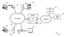
- FIG. 1is a block diagram illustrating an example network environment 100 operable to facilitate diagnostics for service-affecting issues in CPE devices quickly using a single command.
- a headend 105can provide video, data and/or voice service(s) to customer premise equipment (CPE) devices 110 a - d in one or more subscriber groups (e.g., service group(s)).
- CPEcustomer premise equipment
- the CPE devicescan include, for example, a cable modem 110 a , a set top box 110 b , a wireless router including an embedded cable modem 110 c , or a media terminal adapter (MTA) 110 d , among many others (e.g., digital subscriber line (DSL) modem, voice over internet protocol (VoIP) terminal adapter, video game console, digital versatile disc (DVD) player, communications device, etc.).
- a cable modem 110 acan facilitate communications between the headend 105 and a computer 115 a .
- a set top box 110 bcan facilitate communications from the headend 105 to a television or a digital video recorder.
- a wireless router 110 ccan facilitate wireless communications between a computer 115 c and a headend 105 .
- An MTA 110 dcan facilitate communications between a telephone 115 d and a headend 105 .
- the CPE devices 110 a - dcan communicate with the headend 105 via a hybrid fiber-coax (HFC) network 120 .
- the headend 105can include devices such as a cable modem termination system (CMTS) 125 and/or an edge quadrature amplitude modulation (EQAM) device (not shown), or a combined or converged device (not shown) including multiple edge and/or video or data processing functionalities.
- CMTScable modem termination system
- EQAMedge quadrature amplitude modulation
- Such devicescan operate to facilitate communications between a network 130 and the CPE devices 110 a - d .
- the network 130can include one or more networks internal to the headend and/or one or more networks external to the headend (e.g., one or more extranets, the Internet, etc.).
- Data servicescan be handled by the headend 105 through a CMTS 125 .
- the CMTS 125can receive data signals from external device(s) or nodes through network(s) 130 .
- the network(s) 130can operate using internet protocol (IP), sending data packets to and receiving data packets from the headend 105 .
- IPinternet protocol
- the CMTS 125can be paired with a SIP proxy server (not shown) operable to provide voice over internet protocol (VoIP) services with voice connectivity to other subscribers or voice connectivity to a public switched telephone network (PSTN) (not shown).
- VoIPvoice over internet protocol
- PSTNpublic switched telephone network
- one or more video sourcesmay provide streaming data through the network(s) 130 to the CMTS 125 .
- the CMTS 125can forward packets destined for subscribers to an EQAM device used to apply the signal to a carrier waveform.
- the carrier waveformcan include either or both data and video streams, in either or both multicast and unicast (e.g., point-to-point) formats for transmission to a combiner, which can combine multiple signals onto a single fiber for transmission to one or more CPE devices 110 a - d via the hybrid fiber-coax (HFC) network 120 .
- the CMTS 125can apply a baseband signal to a carrier wave and transmit the signal to a combiner for upconversion to a transmission frequency.
- a CPE device 110 a - dWhen a CPE device 110 a - d initially attempts to connect to the headend 105 , the device 110 a - d goes through a ranging and registration process with the headend 105 . Ranging typically involves finding and locking onto a signal and determining a timing offset for the device 110 a - d .
- the registration processtypically includes retrieval of a configuration filename from a dynamic host control protocol (DHCP) server 130 through the network 125 .
- DHCPdynamic host control protocol
- the CPE device 110 a - didentifies a trivial file transfer protocol (TFTP) server 135 where the configuration file is stored.
- TFTPtrivial file transfer protocol
- the CPE device 110 a - dthen requests the configuration file from the TFTP server 135 using the filename provided by the DHCP server. Upon receiving the configuration file, the CPE device 110 a - d can register with the CMTS 120 .
- the CPE devicewill be unable to connect to the headend. This can occur for various reasons, and diagnosis of the issue can involve initiating several complicated commands with results that may not clearly identify whether there is a problem and can waste valuable time.
- the inability to connect to the headendcan occur for a variety of reasons, e.g., including errors in a cable modem, an embedded multimedia terminal adapter (eMTA), a CMTS, a router, or faults in the HFC network itself.
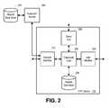
- FIG. 2is a block diagram illustrating an exemplary CPE device 110 operable to diagnose service-affecting issues in a CPE device quickly by using a single command.
- the CPE device 110can include a network interface 210 , a diagnostic logic module 220 , a device results data store 230 , a client interface 240 , and a serial port 250 .
- the network interface 210e.g., an HFC interface
- the network interface 210can be a generic network interface to a local area network (LAN) or wide area network (WAN).
- LANlocal area network
- WANwide area network
- the diagnostics logic module 220can be used to retrieve a testing hierarchy from the HFC network 120 , or other generic network, execute diagnostics commands associated with the testing hierarchy, compare the results from those commands to sets of nominal results associated with the executed diagnostics commands, and print information found on service-affecting issues.
- the device results data store 230can be operable to store information found on service-affecting errors.
- the client interface 240is operable to provide a client interface, for example, to a host computer in the case of a cable modem or MTA device, or to a television for a set top box, etc.
- the serial port 250can be operable to print or communicate data to a device external to the CPE device.
- Execution of diagnostic testingcan be started by entering a diagnostic command through an execution source 260 such as command line interface (CLI), hypertext transfer protocol (HTTP) or simple network management protocol (SNMP).
- CLIcommand line interface
- HTTPhypertext transfer protocol
- SNMPsimple network management protocol
- entering a diagnostic commandmay result in the performance of a deep check of the service that can report the first found issue based upon a testing hierarchy and the particular diagnostic command entered.
- the userwhen executing the diagnostic commands via CLI, the user can be given two standard command options: diagnostic level and intrusive action query. For example, in response to the diagnostic level option, the user may be able to choose between four different diagnostic levels. The first level may print only information on the lowest-level service-affecting error found. The second level may print information on all service-affecting errors. The third level may print information on all service-affecting errors as well as potential service-affecting warnings. The fourth level may print information on all data examined during execution of the command, including all errors and warnings. The user can choose which diagnostic level to run based on the user's experience with the system or simply the level of thoroughness sought by the user. The user can also be provided the option of allowing the system to run intrusive actions during execution of the command.
- the diagnostic commandcan be service-type commands, for example “cm_diag,” “mta_diag,” “voice_diag,” “router_diag” and “video_diag.”
- the service-type commandcan be used to perform a status check of the corresponding CPE device/service component by verifying that everything needed for a selected service-type is functioning properly within the component.
- the header of each command namecorresponds to the type of component to be checked. For example, the “cm” command will check the status of a cable modem, the “mta” command will check the status of the embedded multimedia terminal adapter (eMTA), the “voice” command will check the status of the voice line, and the “router” command will check the status of the router.
- eMTAembedded multimedia terminal adapter
- the service-type commandscan include service diagnostic sub-commands such as “rf_diag,” “cmDhcp_diag,” “mtaDhcp_diag,” among others. These sub-commands can check the status of individual sub-components of the component/service corresponding to the service-type command. When a service-type command is executed, all of the sub-commands associated with that service-type command can be executed. In additional implementations, the sub-commands can be executed separately and individually.
- the diagnostic logic module 220can retrieve a testing hierarchy from the network.
- the testing hierarchycan be retrieved from a local data store.
- the testing hierarchycan identify the service-type commands and their corresponding sub-commands in a prioritized order.
- the service-type commandscan build upon one another. For example, when a main service command is entered, the diagnostic logic module 220 can first execute the service-type commands associated with the service-type diagnostic command initiated by the user based upon the testing hierarchy associated with that service-type command.
- service-type commands and sub-commandscan be added to the testing hierarchy or have their priority within the testing hierarchy altered.
- the diagnostic logic module 220can execute the specified command, and any other commands implicated by the testing hierarchy.
- the diagnostic logiccan store information found on any service-affecting issues in the device results data store 230 and in some implementations, in an external results data store 270 .
- the device results data store 230can be located in the CPE device's non-volatile memory or volatile memory.
- the external results data store 270can be located in memory external to the CPE device and can be accessed via the CPE device's network interface 210 or serial port 250 .
- the diagnostic logic module 220can access the information stored in the device results data store 230 and print or display the information requested by the command to a location external to the device.
- the information requested by the commandcan include any of: only the first service-affecting issue found, all service-affecting issues found, or all service-affecting issues and potential service-affecting warnings found during the diagnostic process.
- FIG. 3is a flowchart illustrating an example process 300 operable to diagnose service-affecting issues in a CPE device.
- the process 300can start at stage 305 when a diagnostic command is entered, for example, via CLI, HTTP, or SNMP.
- the commandcan be entered, for example, using a service interface (e.g., an execution source 260 or serial port 250 of FIG. 2 ).
- the diagnostic commandcan be a service-type diagnostic command including, for example, “cm_diag,” “mta_diag,” “voice_diag,” “router_diag” or “video_diag.”
- the diagnostic commandcan be a service-type diagnostic sub-command including, for example, “rf_diag,” “cmDhcp_diag,” “mtaDhcp_diag,” etc.
- the CPE devicecan retrieve a testing hierarchy through the HFC network.
- the testing hierarchycan be retrieved, for example, from a test source (e.g., execution source 260 of FIG. 2 or diagnostics logic 220 of FIG. 2 ).
- the testing hierarchycan list the service-type diagnostic commands and the service-type diagnostic sub-commands in order starting with the lowest-level diagnostic. For example, the service-type diagnostic commands and the service diagnostic sub-commands can be listed in order from the lowest-level diagnostic to the highest-level diagnostic.
- a determinationcan be made as to what diagnostic tests should be conducted based on the received diagnostic command and those diagnostic tests can be consolidated.
- the determinationcan be made, for example, by a diagnostic logic (e.g., diagnostic logic 220 of FIG. 2 ).
- the diagnostics logic 220can remove any tests from the testing hierarchy that are unnecessary based on the particular diagnostic command received.
- the diagnostics logic 220can add to the testing hierarchy diagnostic tests implicated by a received diagnostic command.
- the diagnostic logiccan determine whether the diagnostic command initiated is a cable modem service diagnostic command. The determination can be made, for example, by a diagnostics logic (e.g., diagnostics logic 220 of FIG. 2 ). In some implementations, the name of the command can be compared with known commands to determine what type of service is associated with the diagnostic command initiated by the user.
- a diagnostics logice.g., diagnostics logic 220 of FIG. 2
- the name of the commandcan be compared with known commands to determine what type of service is associated with the diagnostic command initiated by the user.
- the process 300can proceed to stage 325 and execute the cable modem diagnostic.
- the cable modem diagnosticcan be executed, for example, by a diagnostic logic (e.g., diagnostic logic 220 of FIG. 2 ).
- the diagnostic logiccan print or write the results of the diagnostic test to a results data store (e.g., an output log).
- the diagnostic logiccan then proceed to stage 330 .
- the diagnostic logiccan determine whether the diagnostic command initiated by the user is an embedded multimedia terminal adapter (eMTA) diagnostic command or a lower-level diagnostic command. The determination can be made, for example, by a diagnostic logic (e.g., diagnostic logic 220 of FIG. 2 ). If the eMTA diagnostic is the commanded diagnostic or is a lower listed diagnostic than the commanded diagnostic, then the diagnostic logic can proceed to stage 335 and execute the eMTA diagnostic. In some implementations, the diagnostic logic can then print or write the information found during the execution of the eMTA diagnostic to the results data store (e.g., an output log).
- the results data storee.g., an output log
- the process 300can proceed to stage 340 .
- the diagnostic logiccan determine whether the service-type command initiated by the user is a voice diagnostic command or a lower-level diagnostic. The determination can be made, for example, by a diagnostic logic (e.g., diagnostic logic 220 of FIG. 2 ). If the voice diagnostic is the commanded diagnostic or is a lower listed diagnostic than the commanded diagnostic, then the diagnostic logic can proceed to stage 345 and execute the voice diagnostic. In some implementations, the diagnostic logic can then print or write the information found during the execution of the voice diagnostic to the results data store (e.g., an output log).
- the results data storee.g., an output log
- the process 300can then proceed to stage 350 .
- the diagnostic logiccan determine whether the service-type diagnostic command received from the user is a video diagnostic or a lower-listed diagnostic. The determination can be made, for example, by a diagnostic logic (e.g., diagnostic logic 220 of FIG. 2 ).
- the diagnostic logiccan proceed to stage 355 and execute the video diagnostic.
- the video diagnosticcan be executed, for example, by a diagnostic logic (e.g., diagnostic logic 220 of FIG. 2 ).
- the diagnostic logiccan then print or write the information found during the execution of the video diagnostic to the results data store (e.g., an output log). After executing the video diagnostic, the diagnostic logic can then proceed to stage 360 where the process 300 ends.
- the provisioning logiccan proceed to stage 365 .
- the diagnostic logiccan determine whether the router diagnostic is the commanded diagnostic or is a lower-listed diagnostic than the commanded diagnostic. This determination can be made, for example, by a diagnostic logic (e.g., diagnostic logic 220 of FIG. 2 ).
- the processcan proceed to stage 370 and execute the router diagnostic.
- the router diagnosticcan be executed, for example, by a diagnostic logic (e.g., diagnostic logic 220 of FIG. 2 ).
- the diagnostic logiccan then print or write the information found during the execution of the router diagnostic to the results data store (e.g., an output log).
- the diagnostic logiccan then proceed to stage 360 where the process 300 ends.
- the provisioning logiccan proceed to the end, stage 360 .
- FIG. 4is a block diagram of a hardware configuration 400 operable to diagnose service-affecting issues in a CPE device quickly by using a single command.
- the hardware configuration 400can include a processor 410 , a memory 420 , a storage device 430 , and an input/output device 440 .
- Each of the components 410 , 420 , 430 , and 440can, for example, be interconnected using a system bus 450 .
- the processor 410is capable of processing instructions for execution within the system 400 .
- the processor 410is a single-threaded processor.
- the processor 410is a multi-threaded processor.
- the processor 410is capable of processing instructions stored in the memory 420 or on the storage device 430 .
- the memory 420stores information within the hardware configuration 400 .
- the memory 420is a computer-readable medium.
- the memory 420is a volatile memory unit.
- the memory 420is a non-volatile memory unit.
- the storage device 430is capable of providing mass storage for the device 400 .
- the storage device 430is a computer-readable medium.
- the storage device 430can, for example, include a hard disk device, an optical disk device, flash memory or some other large capacity storage device.
- the input/output device 440provides input/output operations for the hardware configuration 400 .
- the input/output device 440can include one or more of a plain old telephone system (POTS) interface (e.g., an RJ11 connector), a network interface device, e.g., an Ethernet card, a serial communication device, e.g., and RS-232 port, and/or a wireless interface device, e.g., and 802.11 card.
- POTSplain old telephone system
- the input/output devicecan include driver devices configured to receive input data and send output data to other input/output devices, such as one or more subscriber devices 460 (e.g., set top box, cable modem, etc.), as well as sending communications to, and receiving communications from a network 470 .
- subscriber devices 460e.g., set top box, cable modem, etc.
- Such instructionscan, for example, comprise interpreted instructions, such as script instructions, e.g., JavaScript or ECMAScript instructions, or executable code, or other instructions stored in a computer readable medium.
- Implementations of the subject matter and the functional operations described in this specificationcan be provided in digital electronic circuitry, or in computer software, firmware, or hardware, including the structures disclosed in this specification and their structural equivalents, or in combinations of one or more of them.
- Embodiments of the subject matter described in this specificationcan be implemented as one or more computer program products, i.e., one or more modules of computer program instructions encoded on a tangible program carrier for execution by, or to control the operation of, data processing apparatus.
- the tangible program carriercan be a propagated signal or a computer readable medium.
- the propagated signalis an artificially generated signal, e.g., a machine generated electrical, optical, or electromagnetic signal that is generated to encode information for transmission to suitable receiver apparatus for execution by a computer.
- the computer readable mediumcan be a machine readable storage device, a machine readable storage substrate, a memory device, a composition of matter effecting a machine readable propagated signal, or a combination of one or more of them.
- system processorencompasses all apparatus, devices, and machines for processing data, including by way of example a programmable processor, a computer, or multiple processors or computers.
- the system processorcan include, in addition to hardware, code that creates an execution environment for the computer program in question, e.g., code that constitutes processor firmware, a protocol stack, a database management system, an operating system, or a combination of one or more of them.
- a computer program(also known as a program, software, software application, script, or code) can be written in any form of programming language, including compiled or interpreted languages, or declarative or procedural languages, and it can be deployed in any form, including as a stand-alone program or as a module, component, subroutine, or other unit suitable for use in a computing environment.
- a computer programdoes not necessarily correspond to a file in a file system.
- a programcan be stored in a portion of a file that holds other programs or data (e.g., one or more scripts stored in a markup language document), in a single file dedicated to the program in question, or in multiple coordinated files (e.g., files that store one or more modules, sub programs, or portions of code).
- a computer programcan be deployed to be executed on one computer or on multiple computers that are located at one site or distributed across multiple sites and interconnected by a communication network.
- the processes and logic flows described in this specificationare performed by one or more programmable processors executing one or more computer programs to perform functions by operating on input data and generating output thereby tying the process to a particular machine (e.g., a machine programmed to perform the processes described herein).
- the processes and logic flowscan also be performed by, and apparatus can also be implemented as, special purpose logic circuitry, e.g., an FPGA (field programmable gate array) or an ASIC (application specific integrated circuit).
- processors suitable for the execution of a computer programinclude, by way of example, both general and special purpose microprocessors, and any one or more processors of any kind of digital computer.
- a processorwill receive instructions and data from a read only memory or a random access memory or both.
- the elements of a computertypically include a processor for performing instructions and one or more memory devices for storing instructions and data.
- a computerwill also include, or be operatively coupled to receive data from or transfer data to, or both, one or more mass storage devices for storing data, e.g., magnetic, magneto optical disks, or optical disks.
- mass storage devicesfor storing data, e.g., magnetic, magneto optical disks, or optical disks.
- a computerneed not have such devices.
- a computercan be embedded in another device, e.g., a mobile communications device, a telephone, a cable modem, a set-top box, a mobile audio or video player, or a game console, to name just a few
- Computer readable media suitable for storing computer program instructions and datainclude all forms of non volatile memory, media and memory devices, including by way of example semiconductor memory devices, e.g., EPROM, EEPROM, and flash memory devices; magnetic disks, e.g., internal hard disks or removable disks; magneto optical disks; and CD ROM and DVD ROM disks.
- semiconductor memory devicese.g., EPROM, EEPROM, and flash memory devices
- magnetic diskse.g., internal hard disks or removable disks
- magneto optical diskse.g., CD ROM and DVD ROM disks.
- the processor and the memorycan be supplemented by, or incorporated in, special purpose logic circuitry.
- embodiments of the subject matter described in this specificationcan be operable to interface with a computing device having a display, e.g., a CRT (cathode ray tube) or LCD (liquid crystal display) monitor, for displaying information to the user and a keyboard and a pointing device, e.g., a mouse or a trackball, by which the user can provide input to the computer.
- a displaye.g., a CRT (cathode ray tube) or LCD (liquid crystal display) monitor
- keyboard and a pointing devicee.g., a mouse or a trackball
- Other kinds of devicescan be used to provide for interaction with a user as well; for example, feedback provided to the user can be any form of sensory feedback, e.g., visual feedback, auditory feedback, or tactile feedback; and input from the user can be received in any form, including acoustic, speech, or tactile input.
Landscapes
- Engineering & Computer Science (AREA)
- Signal Processing (AREA)
- Multimedia (AREA)
- Computer Networks & Wireless Communication (AREA)
- Health & Medical Sciences (AREA)
- Biomedical Technology (AREA)
- General Health & Medical Sciences (AREA)
- Quality & Reliability (AREA)
- Databases & Information Systems (AREA)
- Debugging And Monitoring (AREA)
Abstract
Description
Claims (24)
Priority Applications (1)
| Application Number | Priority Date | Filing Date | Title |
|---|---|---|---|
| US13/525,777US9270983B1 (en) | 2012-06-18 | 2012-06-18 | Quickly diagnose service and component related issues on a cable modem, multimedia terminal adapter, or gateway |
Applications Claiming Priority (1)
| Application Number | Priority Date | Filing Date | Title |
|---|---|---|---|
| US13/525,777US9270983B1 (en) | 2012-06-18 | 2012-06-18 | Quickly diagnose service and component related issues on a cable modem, multimedia terminal adapter, or gateway |
Publications (1)
| Publication Number | Publication Date |
|---|---|
| US9270983B1true US9270983B1 (en) | 2016-02-23 |
Family
ID=55314826
Family Applications (1)
| Application Number | Title | Priority Date | Filing Date |
|---|---|---|---|
| US13/525,777ActiveUS9270983B1 (en) | 2012-06-18 | 2012-06-18 | Quickly diagnose service and component related issues on a cable modem, multimedia terminal adapter, or gateway |
Country Status (1)
| Country | Link |
|---|---|
| US (1) | US9270983B1 (en) |
Cited By (11)
| Publication number | Priority date | Publication date | Assignee | Title |
|---|---|---|---|---|
| WO2017173917A1 (en)* | 2016-04-07 | 2017-10-12 | 华为技术有限公司 | Method of monitoring data transmission and associated apparatus |
| US20170302994A1 (en)* | 2015-09-25 | 2017-10-19 | Contec, Llc | Set top boxes under test |
| US9900116B2 (en) | 2016-01-04 | 2018-02-20 | Contec, Llc | Test sequences using universal testing system |
| US9960989B2 (en) | 2015-09-25 | 2018-05-01 | Contec, Llc | Universal device testing system |
| US9992084B2 (en) | 2015-11-20 | 2018-06-05 | Contec, Llc | Cable modems/eMTAs under test |
| US10122611B2 (en) | 2015-09-25 | 2018-11-06 | Contec, Llc | Universal device testing interface |
| US10158553B2 (en) | 2015-09-25 | 2018-12-18 | Contec, Llc | Systems and methods for testing electronic devices using master-slave test architectures |
| US10230617B2 (en) | 2015-11-23 | 2019-03-12 | Contec, Llc | Wireless routers under test |
| US10320651B2 (en) | 2015-10-30 | 2019-06-11 | Contec, Llc | Hardware architecture for universal testing system: wireless router test |
| US10578670B2 (en) | 2015-09-25 | 2020-03-03 | Contec, Llc | Core testing machine |
| US10965578B2 (en) | 2015-10-30 | 2021-03-30 | Contec, Llc | Hardware architecture for universal testing system: cable modem test |
Citations (8)
| Publication number | Priority date | Publication date | Assignee | Title |
|---|---|---|---|---|
| US20020019983A1 (en)* | 2000-06-05 | 2002-02-14 | Emsley Brett W. | Testing instrument |
| US6868508B2 (en)* | 2001-08-31 | 2005-03-15 | National Instruments Corporation | System and method enabling hierarchical execution of a test executive subsequence |
| US20060184988A1 (en)* | 2002-04-05 | 2006-08-17 | Spx Corporation | Method and apparatus for real time testing of DTV antenna transmitting systems in time domain under full power |
| US20070076616A1 (en)* | 2005-10-04 | 2007-04-05 | Alcatel | Communication system hierarchical testing systems and methods - entity dependent automatic selection of tests |
| US20080059838A1 (en)* | 2006-09-01 | 2008-03-06 | Melman Phillipe A | Apparatus And Method For Performing Failure Diagnostic Testing of Electronic Equipment |
| US7739717B1 (en)* | 2004-07-13 | 2010-06-15 | The Directv Group, Inc. | System and method for performing diagnostics for a customer IRD in a satellite television system |
| US8209732B2 (en)* | 2007-09-27 | 2012-06-26 | Contec Llc | Arrangement and method for managing testing and repair of set-top boxes |
| US8544051B1 (en)* | 2009-03-30 | 2013-09-24 | Cisco Technology, Inc. | Broadcast solution for cable IPTV |
- 2012
- 2012-06-18USUS13/525,777patent/US9270983B1/enactiveActive
Patent Citations (8)
| Publication number | Priority date | Publication date | Assignee | Title |
|---|---|---|---|---|
| US20020019983A1 (en)* | 2000-06-05 | 2002-02-14 | Emsley Brett W. | Testing instrument |
| US6868508B2 (en)* | 2001-08-31 | 2005-03-15 | National Instruments Corporation | System and method enabling hierarchical execution of a test executive subsequence |
| US20060184988A1 (en)* | 2002-04-05 | 2006-08-17 | Spx Corporation | Method and apparatus for real time testing of DTV antenna transmitting systems in time domain under full power |
| US7739717B1 (en)* | 2004-07-13 | 2010-06-15 | The Directv Group, Inc. | System and method for performing diagnostics for a customer IRD in a satellite television system |
| US20070076616A1 (en)* | 2005-10-04 | 2007-04-05 | Alcatel | Communication system hierarchical testing systems and methods - entity dependent automatic selection of tests |
| US20080059838A1 (en)* | 2006-09-01 | 2008-03-06 | Melman Phillipe A | Apparatus And Method For Performing Failure Diagnostic Testing of Electronic Equipment |
| US8209732B2 (en)* | 2007-09-27 | 2012-06-26 | Contec Llc | Arrangement and method for managing testing and repair of set-top boxes |
| US8544051B1 (en)* | 2009-03-30 | 2013-09-24 | Cisco Technology, Inc. | Broadcast solution for cable IPTV |
Cited By (19)
| Publication number | Priority date | Publication date | Assignee | Title |
|---|---|---|---|---|
| US10122611B2 (en) | 2015-09-25 | 2018-11-06 | Contec, Llc | Universal device testing interface |
| US20170302994A1 (en)* | 2015-09-25 | 2017-10-19 | Contec, Llc | Set top boxes under test |
| US9960989B2 (en) | 2015-09-25 | 2018-05-01 | Contec, Llc | Universal device testing system |
| US11353507B2 (en) | 2015-09-25 | 2022-06-07 | Contec, Llc | Core testing machine |
| US10578670B2 (en) | 2015-09-25 | 2020-03-03 | Contec, Llc | Core testing machine |
| US10158553B2 (en) | 2015-09-25 | 2018-12-18 | Contec, Llc | Systems and methods for testing electronic devices using master-slave test architectures |
| US10277497B2 (en) | 2015-09-25 | 2019-04-30 | Contec, Llc | Systems and methods for testing electronic devices using master-slave test architectures |
| US10291959B2 (en)* | 2015-09-25 | 2019-05-14 | Contec, Llc | Set top boxes under test |
| US10298483B2 (en) | 2015-09-25 | 2019-05-21 | Contec, Llc | Universal device testing interface |
| US12155552B2 (en) | 2015-10-30 | 2024-11-26 | Contec, Llc | Hardware architecture for universal testing system: cable modem test |
| US10965578B2 (en) | 2015-10-30 | 2021-03-30 | Contec, Llc | Hardware architecture for universal testing system: cable modem test |
| US10581719B2 (en) | 2015-10-30 | 2020-03-03 | Contec, Llc | Hardware architecture for universal testing system: wireless router test |
| US10320651B2 (en) | 2015-10-30 | 2019-06-11 | Contec, Llc | Hardware architecture for universal testing system: wireless router test |
| US9992084B2 (en) | 2015-11-20 | 2018-06-05 | Contec, Llc | Cable modems/eMTAs under test |
| US10581718B2 (en) | 2015-11-23 | 2020-03-03 | Contec, Llc | Wireless devices under test |
| US10230617B2 (en) | 2015-11-23 | 2019-03-12 | Contec, Llc | Wireless routers under test |
| US10116397B2 (en) | 2016-01-04 | 2018-10-30 | Contec, Llc | Test sequences using universal testing system |
| US9900116B2 (en) | 2016-01-04 | 2018-02-20 | Contec, Llc | Test sequences using universal testing system |
| WO2017173917A1 (en)* | 2016-04-07 | 2017-10-12 | 华为技术有限公司 | Method of monitoring data transmission and associated apparatus |
Similar Documents
| Publication | Publication Date | Title |
|---|---|---|
| US9270983B1 (en) | Quickly diagnose service and component related issues on a cable modem, multimedia terminal adapter, or gateway | |
| US8509072B2 (en) | Network congestion analysis | |
| US9621413B1 (en) | Displaying dynamic host configuration protocol (DHCP) transaction states using a DHCP relay agent | |
| US11863420B2 (en) | Diagnosing faults in a multimedia over coax alliance (MoCA) local area network (LAN) including a WiFi segment | |
| US9823988B2 (en) | System and method of test iteration via property chaining | |
| US9059939B2 (en) | End-to-end network service assurance solution | |
| US9077760B2 (en) | Broadband communications | |
| US8806550B1 (en) | Rules engine for troubleshooting video content delivery network | |
| CN101072132B (en) | Diagnostic tool and method for troubleshooting multicast connectivity flow problem(s) in a layer 2 aggregation network | |
| US8191099B2 (en) | Automated analysis of collected field data for error detection | |
| US20120078566A1 (en) | Network Test Conflict Checking | |
| US20160330085A1 (en) | Method and apparatus for generating configuration information for a communication system | |
| WO2011012173A1 (en) | Service monitoring and service problem diagnosing in communications network | |
| CA3175654A1 (en) | Network management for band splits | |
| CN101662379A (en) | Method, equipment and system for maintaining terminal equipment | |
| CN111865628A (en) | Statistical system, method, server and storage medium for household broadband failure affecting users | |
| US8788647B1 (en) | Load balancing for network devices | |
| US8477807B1 (en) | Upstream ranging in communications devices | |
| US20250141775A1 (en) | Systems and techniques for assessing a customer premises equipment device | |
| US9268630B1 (en) | Automatic recovery from non-functional download | |
| US20140149581A1 (en) | Quality of service monitoring device and method of monitoring quality of service | |
| US9479440B1 (en) | Specifying and enforcing IPV4 and IPV6 CPE limits | |
| US9525582B1 (en) | Selectively ordering application of provisioning from multiple sources for network equipment | |
| CN108111880B (en) | Obstacle removing method and obstacle removing system | |
| US9298569B1 (en) | Log storage and retrieval for broadband communications devices |
Legal Events
| Date | Code | Title | Description |
|---|---|---|---|
| AS | Assignment | Owner name:ARRIS GROUP, INC., GEORGIA Free format text:ASSIGNMENT OF ASSIGNORS INTEREST;ASSIGNOR:HARE, WILLIAM CHARLES, JR;REEL/FRAME:028408/0357 Effective date:20120619 | |
| AS | Assignment | Owner name:ARRIS ENTERPRISES, INC., GEORGIA Free format text:MERGER;ASSIGNOR:ARRIS GROUP, INC.;REEL/FRAME:030228/0406 Effective date:20130416 | |
| AS | Assignment | Owner name:BANK OF AMERICA, N.A., AS ADMINISTRATIVE AGENT, ILLINOIS Free format text:SECURITY AGREEMENT;ASSIGNORS:ARRIS GROUP, INC.;ARRIS ENTERPRISES, INC.;ARRIS SOLUTIONS, INC.;AND OTHERS;REEL/FRAME:030498/0023 Effective date:20130417 Owner name:BANK OF AMERICA, N.A., AS ADMINISTRATIVE AGENT, IL Free format text:SECURITY AGREEMENT;ASSIGNORS:ARRIS GROUP, INC.;ARRIS ENTERPRISES, INC.;ARRIS SOLUTIONS, INC.;AND OTHERS;REEL/FRAME:030498/0023 Effective date:20130417 | |
| STCF | Information on status: patent grant | Free format text:PATENTED CASE | |
| AS | Assignment | Owner name:ARRIS ENTERPRISES LLC, PENNSYLVANIA Free format text:CHANGE OF NAME;ASSIGNOR:ARRIS ENTERPRISES INC;REEL/FRAME:041995/0031 Effective date:20151231 | |
| AS | Assignment | Owner name:ARRIS HOLDINGS CORP. OF ILLINOIS, INC., PENNSYLVAN Free format text:TERMINATION AND RELEASE OF SECURITY INTEREST IN PATENTS;ASSIGNOR:BANK OF AMERICA, N.A., AS ADMINISTRATIVE AGENT;REEL/FRAME:048825/0294 Effective date:20190404 Owner name:ARRIS GROUP, INC., PENNSYLVANIA Free format text:TERMINATION AND RELEASE OF SECURITY INTEREST IN PATENTS;ASSIGNOR:BANK OF AMERICA, N.A., AS ADMINISTRATIVE AGENT;REEL/FRAME:048825/0294 Effective date:20190404 Owner name:TEXSCAN CORPORATION, PENNSYLVANIA Free format text:TERMINATION AND RELEASE OF SECURITY INTEREST IN PATENTS;ASSIGNOR:BANK OF AMERICA, N.A., AS ADMINISTRATIVE AGENT;REEL/FRAME:048825/0294 Effective date:20190404 Owner name:ARRIS SOLUTIONS, INC., PENNSYLVANIA Free format text:TERMINATION AND RELEASE OF SECURITY INTEREST IN PATENTS;ASSIGNOR:BANK OF AMERICA, N.A., AS ADMINISTRATIVE AGENT;REEL/FRAME:048825/0294 Effective date:20190404 Owner name:IMEDIA CORPORATION, PENNSYLVANIA Free format text:TERMINATION AND RELEASE OF SECURITY INTEREST IN PATENTS;ASSIGNOR:BANK OF AMERICA, N.A., AS ADMINISTRATIVE AGENT;REEL/FRAME:048825/0294 Effective date:20190404 Owner name:GIC INTERNATIONAL HOLDCO LLC, PENNSYLVANIA Free format text:TERMINATION AND RELEASE OF SECURITY INTEREST IN PATENTS;ASSIGNOR:BANK OF AMERICA, N.A., AS ADMINISTRATIVE AGENT;REEL/FRAME:048825/0294 Effective date:20190404 Owner name:NEXTLEVEL SYSTEMS (PUERTO RICO), INC., PENNSYLVANI Free format text:TERMINATION AND RELEASE OF SECURITY INTEREST IN PATENTS;ASSIGNOR:BANK OF AMERICA, N.A., AS ADMINISTRATIVE AGENT;REEL/FRAME:048825/0294 Effective date:20190404 Owner name:GENERAL INSTRUMENT INTERNATIONAL HOLDINGS, INC., P Free format text:TERMINATION AND RELEASE OF SECURITY INTEREST IN PATENTS;ASSIGNOR:BANK OF AMERICA, N.A., AS ADMINISTRATIVE AGENT;REEL/FRAME:048825/0294 Effective date:20190404 Owner name:MOTOROLA WIRELINE NETWORKS, INC., PENNSYLVANIA Free format text:TERMINATION AND RELEASE OF SECURITY INTEREST IN PATENTS;ASSIGNOR:BANK OF AMERICA, N.A., AS ADMINISTRATIVE AGENT;REEL/FRAME:048825/0294 Effective date:20190404 Owner name:JERROLD DC RADIO, INC., PENNSYLVANIA Free format text:TERMINATION AND RELEASE OF SECURITY INTEREST IN PATENTS;ASSIGNOR:BANK OF AMERICA, N.A., AS ADMINISTRATIVE AGENT;REEL/FRAME:048825/0294 Effective date:20190404 Owner name:ACADIA AIC, INC., PENNSYLVANIA Free format text:TERMINATION AND RELEASE OF SECURITY INTEREST IN PATENTS;ASSIGNOR:BANK OF AMERICA, N.A., AS ADMINISTRATIVE AGENT;REEL/FRAME:048825/0294 Effective date:20190404 Owner name:UCENTRIC SYSTEMS, INC., PENNSYLVANIA Free format text:TERMINATION AND RELEASE OF SECURITY INTEREST IN PATENTS;ASSIGNOR:BANK OF AMERICA, N.A., AS ADMINISTRATIVE AGENT;REEL/FRAME:048825/0294 Effective date:20190404 Owner name:GENERAL INSTRUMENT AUTHORIZATION SERVICES, INC., P Free format text:TERMINATION AND RELEASE OF SECURITY INTEREST IN PATENTS;ASSIGNOR:BANK OF AMERICA, N.A., AS ADMINISTRATIVE AGENT;REEL/FRAME:048825/0294 Effective date:20190404 Owner name:AEROCAST, INC., PENNSYLVANIA Free format text:TERMINATION AND RELEASE OF SECURITY INTEREST IN PATENTS;ASSIGNOR:BANK OF AMERICA, N.A., AS ADMINISTRATIVE AGENT;REEL/FRAME:048825/0294 Effective date:20190404 Owner name:THE GI REALTY TRUST 1996, PENNSYLVANIA Free format text:TERMINATION AND RELEASE OF SECURITY INTEREST IN PATENTS;ASSIGNOR:BANK OF AMERICA, N.A., AS ADMINISTRATIVE AGENT;REEL/FRAME:048825/0294 Effective date:20190404 Owner name:CCE SOFTWARE LLC, PENNSYLVANIA Free format text:TERMINATION AND RELEASE OF SECURITY INTEREST IN PATENTS;ASSIGNOR:BANK OF AMERICA, N.A., AS ADMINISTRATIVE AGENT;REEL/FRAME:048825/0294 Effective date:20190404 Owner name:SETJAM, INC., PENNSYLVANIA Free format text:TERMINATION AND RELEASE OF SECURITY INTEREST IN PATENTS;ASSIGNOR:BANK OF AMERICA, N.A., AS ADMINISTRATIVE AGENT;REEL/FRAME:048825/0294 Effective date:20190404 Owner name:LEAPSTONE SYSTEMS, INC., PENNSYLVANIA Free format text:TERMINATION AND RELEASE OF SECURITY INTEREST IN PATENTS;ASSIGNOR:BANK OF AMERICA, N.A., AS ADMINISTRATIVE AGENT;REEL/FRAME:048825/0294 Effective date:20190404 Owner name:SUNUP DESIGN SYSTEMS, INC., PENNSYLVANIA Free format text:TERMINATION AND RELEASE OF SECURITY INTEREST IN PATENTS;ASSIGNOR:BANK OF AMERICA, N.A., AS ADMINISTRATIVE AGENT;REEL/FRAME:048825/0294 Effective date:20190404 Owner name:ARRIS KOREA, INC., PENNSYLVANIA Free format text:TERMINATION AND RELEASE OF SECURITY INTEREST IN PATENTS;ASSIGNOR:BANK OF AMERICA, N.A., AS ADMINISTRATIVE AGENT;REEL/FRAME:048825/0294 Effective date:20190404 Owner name:MODULUS VIDEO, INC., PENNSYLVANIA Free format text:TERMINATION AND RELEASE OF SECURITY INTEREST IN PATENTS;ASSIGNOR:BANK OF AMERICA, N.A., AS ADMINISTRATIVE AGENT;REEL/FRAME:048825/0294 Effective date:20190404 Owner name:GENERAL INSTRUMENT CORPORATION, PENNSYLVANIA Free format text:TERMINATION AND RELEASE OF SECURITY INTEREST IN PATENTS;ASSIGNOR:BANK OF AMERICA, N.A., AS ADMINISTRATIVE AGENT;REEL/FRAME:048825/0294 Effective date:20190404 Owner name:BIG BAND NETWORKS, INC., PENNSYLVANIA Free format text:TERMINATION AND RELEASE OF SECURITY INTEREST IN PATENTS;ASSIGNOR:BANK OF AMERICA, N.A., AS ADMINISTRATIVE AGENT;REEL/FRAME:048825/0294 Effective date:20190404 Owner name:ARRIS ENTERPRISES, INC., PENNSYLVANIA Free format text:TERMINATION AND RELEASE OF SECURITY INTEREST IN PATENTS;ASSIGNOR:BANK OF AMERICA, N.A., AS ADMINISTRATIVE AGENT;REEL/FRAME:048825/0294 Effective date:20190404 Owner name:GIC INTERNATIONAL CAPITAL LLC, PENNSYLVANIA Free format text:TERMINATION AND RELEASE OF SECURITY INTEREST IN PATENTS;ASSIGNOR:BANK OF AMERICA, N.A., AS ADMINISTRATIVE AGENT;REEL/FRAME:048825/0294 Effective date:20190404 Owner name:QUANTUM BRIDGE COMMUNICATIONS, INC., PENNSYLVANIA Free format text:TERMINATION AND RELEASE OF SECURITY INTEREST IN PATENTS;ASSIGNOR:BANK OF AMERICA, N.A., AS ADMINISTRATIVE AGENT;REEL/FRAME:048825/0294 Effective date:20190404 Owner name:4HOME, INC., PENNSYLVANIA Free format text:TERMINATION AND RELEASE OF SECURITY INTEREST IN PATENTS;ASSIGNOR:BANK OF AMERICA, N.A., AS ADMINISTRATIVE AGENT;REEL/FRAME:048825/0294 Effective date:20190404 Owner name:BROADBUS TECHNOLOGIES, INC., PENNSYLVANIA Free format text:TERMINATION AND RELEASE OF SECURITY INTEREST IN PATENTS;ASSIGNOR:BANK OF AMERICA, N.A., AS ADMINISTRATIVE AGENT;REEL/FRAME:048825/0294 Effective date:20190404 Owner name:NETOPIA, INC., PENNSYLVANIA Free format text:TERMINATION AND RELEASE OF SECURITY INTEREST IN PATENTS;ASSIGNOR:BANK OF AMERICA, N.A., AS ADMINISTRATIVE AGENT;REEL/FRAME:048825/0294 Effective date:20190404 Owner name:POWER GUARD, INC., PENNSYLVANIA Free format text:TERMINATION AND RELEASE OF SECURITY INTEREST IN PATENTS;ASSIGNOR:BANK OF AMERICA, N.A., AS ADMINISTRATIVE AGENT;REEL/FRAME:048825/0294 Effective date:20190404 Owner name:ARRIS HOLDINGS CORP. OF ILLINOIS, INC., PENNSYLVANIA Free format text:TERMINATION AND RELEASE OF SECURITY INTEREST IN PATENTS;ASSIGNOR:BANK OF AMERICA, N.A., AS ADMINISTRATIVE AGENT;REEL/FRAME:048825/0294 Effective date:20190404 Owner name:GENERAL INSTRUMENT AUTHORIZATION SERVICES, INC., PENNSYLVANIA Free format text:TERMINATION AND RELEASE OF SECURITY INTEREST IN PATENTS;ASSIGNOR:BANK OF AMERICA, N.A., AS ADMINISTRATIVE AGENT;REEL/FRAME:048825/0294 Effective date:20190404 Owner name:GENERAL INSTRUMENT INTERNATIONAL HOLDINGS, INC., PENNSYLVANIA Free format text:TERMINATION AND RELEASE OF SECURITY INTEREST IN PATENTS;ASSIGNOR:BANK OF AMERICA, N.A., AS ADMINISTRATIVE AGENT;REEL/FRAME:048825/0294 Effective date:20190404 Owner name:NEXTLEVEL SYSTEMS (PUERTO RICO), INC., PENNSYLVANIA Free format text:TERMINATION AND RELEASE OF SECURITY INTEREST IN PATENTS;ASSIGNOR:BANK OF AMERICA, N.A., AS ADMINISTRATIVE AGENT;REEL/FRAME:048825/0294 Effective date:20190404 | |
| AS | Assignment | Owner name:ARRIS ENTERPRISES LLC, GEORGIA Free format text:CHANGE OF NAME;ASSIGNOR:ARRIS ENTERPRISES, INC.;REEL/FRAME:049586/0470 Effective date:20151231 | |
| AS | Assignment | Owner name:WILMINGTON TRUST, NATIONAL ASSOCIATION, AS COLLATE Free format text:PATENT SECURITY AGREEMENT;ASSIGNOR:ARRIS ENTERPRISES LLC;REEL/FRAME:049820/0495 Effective date:20190404 Owner name:JPMORGAN CHASE BANK, N.A., NEW YORK Free format text:ABL SECURITY AGREEMENT;ASSIGNORS:COMMSCOPE, INC. OF NORTH CAROLINA;COMMSCOPE TECHNOLOGIES LLC;ARRIS ENTERPRISES LLC;AND OTHERS;REEL/FRAME:049892/0396 Effective date:20190404 Owner name:JPMORGAN CHASE BANK, N.A., NEW YORK Free format text:TERM LOAN SECURITY AGREEMENT;ASSIGNORS:COMMSCOPE, INC. OF NORTH CAROLINA;COMMSCOPE TECHNOLOGIES LLC;ARRIS ENTERPRISES LLC;AND OTHERS;REEL/FRAME:049905/0504 Effective date:20190404 Owner name:WILMINGTON TRUST, NATIONAL ASSOCIATION, AS COLLATERAL AGENT, CONNECTICUT Free format text:PATENT SECURITY AGREEMENT;ASSIGNOR:ARRIS ENTERPRISES LLC;REEL/FRAME:049820/0495 Effective date:20190404 | |
| MAFP | Maintenance fee payment | Free format text:PAYMENT OF MAINTENANCE FEE, 4TH YEAR, LARGE ENTITY (ORIGINAL EVENT CODE: M1551); ENTITY STATUS OF PATENT OWNER: LARGE ENTITY Year of fee payment:4 | |
| AS | Assignment | Owner name:WILMINGTON TRUST, DELAWARE Free format text:SECURITY INTEREST;ASSIGNORS:ARRIS SOLUTIONS, INC.;ARRIS ENTERPRISES LLC;COMMSCOPE TECHNOLOGIES LLC;AND OTHERS;REEL/FRAME:060752/0001 Effective date:20211115 | |
| MAFP | Maintenance fee payment | Free format text:PAYMENT OF MAINTENANCE FEE, 8TH YEAR, LARGE ENTITY (ORIGINAL EVENT CODE: M1552); ENTITY STATUS OF PATENT OWNER: LARGE ENTITY Year of fee payment:8 | |
| AS | Assignment | Owner name:APOLLO ADMINISTRATIVE AGENCY LLC, NEW YORK Free format text:SECURITY INTEREST;ASSIGNORS:ARRIS ENTERPRISES LLC;COMMSCOPE TECHNOLOGIES LLC;COMMSCOPE INC., OF NORTH CAROLINA;AND OTHERS;REEL/FRAME:069889/0114 Effective date:20241217 | |
| AS | Assignment | Owner name:RUCKUS WIRELESS, LLC (F/K/A RUCKUS WIRELESS, INC.), NORTH CAROLINA Free format text:RELEASE OF SECURITY INTEREST AT REEL/FRAME 049905/0504;ASSIGNOR:JPMORGAN CHASE BANK, N.A., AS COLLATERAL AGENT;REEL/FRAME:071477/0255 Effective date:20241217 Owner name:COMMSCOPE TECHNOLOGIES LLC, NORTH CAROLINA Free format text:RELEASE OF SECURITY INTEREST AT REEL/FRAME 049905/0504;ASSIGNOR:JPMORGAN CHASE BANK, N.A., AS COLLATERAL AGENT;REEL/FRAME:071477/0255 Effective date:20241217 Owner name:COMMSCOPE, INC. OF NORTH CAROLINA, NORTH CAROLINA Free format text:RELEASE OF SECURITY INTEREST AT REEL/FRAME 049905/0504;ASSIGNOR:JPMORGAN CHASE BANK, N.A., AS COLLATERAL AGENT;REEL/FRAME:071477/0255 Effective date:20241217 Owner name:ARRIS SOLUTIONS, INC., NORTH CAROLINA Free format text:RELEASE OF SECURITY INTEREST AT REEL/FRAME 049905/0504;ASSIGNOR:JPMORGAN CHASE BANK, N.A., AS COLLATERAL AGENT;REEL/FRAME:071477/0255 Effective date:20241217 Owner name:ARRIS TECHNOLOGY, INC., NORTH CAROLINA Free format text:RELEASE OF SECURITY INTEREST AT REEL/FRAME 049905/0504;ASSIGNOR:JPMORGAN CHASE BANK, N.A., AS COLLATERAL AGENT;REEL/FRAME:071477/0255 Effective date:20241217 Owner name:ARRIS ENTERPRISES LLC (F/K/A ARRIS ENTERPRISES, INC.), NORTH CAROLINA Free format text:RELEASE OF SECURITY INTEREST AT REEL/FRAME 049905/0504;ASSIGNOR:JPMORGAN CHASE BANK, N.A., AS COLLATERAL AGENT;REEL/FRAME:071477/0255 Effective date:20241217 |