US9270875B2 - Dual image capture processing - Google Patents
Dual image capture processingDownload PDFInfo
- Publication number
- US9270875B2 US9270875B2US13/335,028US201113335028AUS9270875B2US 9270875 B2US9270875 B2US 9270875B2US 201113335028 AUS201113335028 AUS 201113335028AUS 9270875 B2US9270875 B2US 9270875B2
- Authority
- US
- United States
- Prior art keywords
- image
- monoscopic
- enhanced
- sensor
- processing
- Prior art date
- Legal status (The legal status is an assumption and is not a legal conclusion. Google has not performed a legal analysis and makes no representation as to the accuracy of the status listed.)
- Active, expires
Links
- 238000012545processingMethods0.000titleclaimsabstractdescription141
- 230000009977dual effectEffects0.000title1
- 238000000034methodMethods0.000claimsdescription56
- 230000008569processEffects0.000claimsdescription44
- 230000007547defectEffects0.000claimsdescription12
- 238000003672processing methodMethods0.000claims7
- 238000003384imaging methodMethods0.000abstractdescription34
- 238000010586diagramMethods0.000description8
- 230000015556catabolic processEffects0.000description6
- 238000006731degradation reactionMethods0.000description6
- 238000013459approachMethods0.000description4
- 230000006835compressionEffects0.000description4
- 238000007906compressionMethods0.000description4
- 238000012937correctionMethods0.000description4
- 238000003705background correctionMethods0.000description3
- 230000002950deficientEffects0.000description3
- 230000006870functionEffects0.000description3
- 230000003287optical effectEffects0.000description3
- 230000009467reductionEffects0.000description3
- 241000023320Luma <angiosperm>Species0.000description2
- 238000003491arrayMethods0.000description2
- 230000008901benefitEffects0.000description2
- 230000002596correlated effectEffects0.000description2
- 238000001514detection methodMethods0.000description2
- 238000001914filtrationMethods0.000description2
- 238000003707image sharpeningMethods0.000description2
- OSWPMRLSEDHDFF-UHFFFAOYSA-Nmethyl salicylateChemical compoundCOC(=O)C1=CC=CC=C1OOSWPMRLSEDHDFF-UHFFFAOYSA-N0.000description2
- 238000012986modificationMethods0.000description2
- 230000004048modificationEffects0.000description2
- 229910052754neonInorganic materials0.000description2
- GKAOGPIIYCISHV-UHFFFAOYSA-Nneon atomChemical compound[Ne]GKAOGPIIYCISHV-UHFFFAOYSA-N0.000description2
- 239000004065semiconductorSubstances0.000description2
- 238000012935AveragingMethods0.000description1
- 230000006978adaptationEffects0.000description1
- 230000008859changeEffects0.000description1
- 238000006243chemical reactionMethods0.000description1
- 230000000295complement effectEffects0.000description1
- 230000000875corresponding effectEffects0.000description1
- 238000013461designMethods0.000description1
- 238000011143downstream manufacturingMethods0.000description1
- 230000000694effectsEffects0.000description1
- 238000010191image analysisMethods0.000description1
- 230000006855networkingEffects0.000description1
- 239000013307optical fiberSubstances0.000description1
- 238000012805post-processingMethods0.000description1
- 230000011664signalingEffects0.000description1
- 230000000153supplemental effectEffects0.000description1
- 230000002123temporal effectEffects0.000description1
Images


Classifications
- H—ELECTRICITY
- H04—ELECTRIC COMMUNICATION TECHNIQUE
- H04N—PICTORIAL COMMUNICATION, e.g. TELEVISION
- H04N13/00—Stereoscopic video systems; Multi-view video systems; Details thereof
- H04N13/20—Image signal generators
- H04N13/286—Image signal generators having separate monoscopic and stereoscopic modes
- H04N13/289—Switching between monoscopic and stereoscopic modes
- H—ELECTRICITY
- H04—ELECTRIC COMMUNICATION TECHNIQUE
- H04N—PICTORIAL COMMUNICATION, e.g. TELEVISION
- H04N23/00—Cameras or camera modules comprising electronic image sensors; Control thereof
- H04N23/45—Cameras or camera modules comprising electronic image sensors; Control thereof for generating image signals from two or more image sensors being of different type or operating in different modes, e.g. with a CMOS sensor for moving images in combination with a charge-coupled device [CCD] for still images
- H04N5/2258—
- H04N13/0289—
- H—ELECTRICITY
- H04—ELECTRIC COMMUNICATION TECHNIQUE
- H04N—PICTORIAL COMMUNICATION, e.g. TELEVISION
- H04N23/00—Cameras or camera modules comprising electronic image sensors; Control thereof
- H04N23/60—Control of cameras or camera modules
- H04N23/667—Camera operation mode switching, e.g. between still and video, sport and normal or high- and low-resolution modes
- H—ELECTRICITY
- H04—ELECTRIC COMMUNICATION TECHNIQUE
- H04N—PICTORIAL COMMUNICATION, e.g. TELEVISION
- H04N23/00—Cameras or camera modules comprising electronic image sensors; Control thereof
- H04N23/70—Circuitry for compensating brightness variation in the scene
- H04N23/741—Circuitry for compensating brightness variation in the scene by increasing the dynamic range of the image compared to the dynamic range of the electronic image sensors
- H—ELECTRICITY
- H04—ELECTRIC COMMUNICATION TECHNIQUE
- H04N—PICTORIAL COMMUNICATION, e.g. TELEVISION
- H04N23/00—Cameras or camera modules comprising electronic image sensors; Control thereof
- H04N23/80—Camera processing pipelines; Components thereof
- H04N23/81—Camera processing pipelines; Components thereof for suppressing or minimising disturbance in the image signal generation
- H—ELECTRICITY
- H04—ELECTRIC COMMUNICATION TECHNIQUE
- H04N—PICTORIAL COMMUNICATION, e.g. TELEVISION
- H04N23/00—Cameras or camera modules comprising electronic image sensors; Control thereof
- H04N23/90—Arrangement of cameras or camera modules, e.g. multiple cameras in TV studios or sports stadiums
- H—ELECTRICITY
- H04—ELECTRIC COMMUNICATION TECHNIQUE
- H04N—PICTORIAL COMMUNICATION, e.g. TELEVISION
- H04N23/00—Cameras or camera modules comprising electronic image sensors; Control thereof
- H04N23/95—Computational photography systems, e.g. light-field imaging systems
- H04N23/951—Computational photography systems, e.g. light-field imaging systems by using two or more images to influence resolution, frame rate or aspect ratio
- H—ELECTRICITY
- H04—ELECTRIC COMMUNICATION TECHNIQUE
- H04N—PICTORIAL COMMUNICATION, e.g. TELEVISION
- H04N23/00—Cameras or camera modules comprising electronic image sensors; Control thereof
- H04N23/95—Computational photography systems, e.g. light-field imaging systems
- H04N23/958—Computational photography systems, e.g. light-field imaging systems for extended depth of field imaging
- H04N5/23232—
- H04N5/23245—
- H04N5/2355—
Definitions
- HDRhigh dynamic range
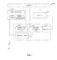
- FIG. 1is a block diagram of one embodiment of an image processing circuitry according to the present disclosure.
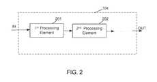
- FIGS. 2-5are block diagrams of embodiments of an image signal processing pipeline implemented by the pipeline processing logic from the image processing circuitry of FIG. 1 .
- FIG. 6is a block diagram illustrating an embodiment of an electronic device employing the image processing circuitry of FIG. 1 .
- FIGS. 7-9are flow chart diagrams depicting various functionalities of embodiments of image processing circuitry of FIG. 1 .
- This disclosurepertains to a device, method, computer useable medium, and processor programmed to automatically utilize simultaneous image captures in an image processing pipeline in a digital camera or digital video camera.
- processorprogrammed to automatically utilize simultaneous image captures in an image processing pipeline in a digital camera or digital video camera.
- a digital imaging devicemay include an image sensor that provides a number of light-detecting elements (e.g., photodetectors) configured to convert light detected by the image sensor into an electrical signal.
- An image sensormay also include a color filter array that filters light captured by the image sensor to capture color information.
- the image data captured by the image sensormay then be processed by an image processing pipeline circuitry, which may apply a number of various image processing operations to the image data to generate a full color image that may be displayed for viewing on a display device, such as a monitor.
- HDR image processingrequires multiple images to be captured sequentially and then combined to yield an HDR with enhanced image characteristics.
- HDR image processingmultiple images are captured sequentially by a single image sensor at different exposures and are combined to produce a single image with higher dynamic range than possible with capture of a single image. For example, capture of an outdoor night time shot with a neon sign might result in either over-exposure of the neon sign or under-exposure of the other portions of the scene.
- capture both an over-exposed image and an under-exposed image and combining the multiple imagescan yield an HDR image with both adequate exposure for both the sign and the scene.
- This approachis often called exposure bracketing, but a requirement is that the images captured must be substantially similar even though taken sequentially to prevent substantial introduction of blurring or ghosting.
- Embodiments of the present disclosureprovide enhanced image processing by utilizing multiple images that are captured simultaneously.
- FIG. 1a block diagram of one embodiment of an image processing circuitry 100 is shown for an imaging device 150 .
- the illustrated imaging device 150may be provided as a digital camera configured to acquire both still images and moving images (e.g., video).
- the device 150may include multiple lenses 110 and multiple image sensors 101 configured to capture and convert light into electrical signals.
- an individual image sensormay include a CMOS (complementary metal-oxide-semiconductor) image sensor (e.g., a CMOS active-pixel sensor (APS)) or a CCD (charge-coupled device) sensor.
- CMOScomplementary metal-oxide-semiconductor
- APSCMOS active-pixel sensor
- CCDcharge-coupled device
- an imaging device 150 with multiple cameras or image sensorswould be to increase the number of dimensions represented in a displayed image.
- An example of this type of functionalityis a stereoscopic camera which typically has two cameras (e.g., two image sensors).
- Embodiments of the present disclosuremay have more than two cameras or image sensors.
- embodiments of an imaging device 150may have modes of operation such that one mode may allow for the imaging device 150 to capture a 2-dimensional (2D) image; a second mode may allow for the imaging device to capture a multi-dimensional image (e.g., 3D image), and a third mode may allow the imaging device to simultaneously capture multiple images and use them to produce one or more 2D enhanced images for which an image processing effect has been applied.
- some embodiments of the present disclosureencompass a configurable and adaptable multi-imager camera architecture which operates in either a stereoscopic (3D) mode, monoscopic (single imager 2D) mode, and a combinational monoscopic (multiple imager 2D) mode.
- mode configurationinvolves user selection, while adaptation can be automatic or prompted mode operation.
- monoscopic modemay be used in normally sufficient situations but switched to combinational monoscopic operations when the need is detected by control logic 105 .
- the image processing circuitry 100may include various subcomponents and/or discrete units of logic that collectively form an image processing “pipeline” for performing each of various image processing steps. These subcomponents may be implemented using hardware (e.g., digital signal processors or ASICs (application-specific integrated circuits)) or software, or via a combination of hardware and software components. The various image processing operations may be provided by the image processing circuitry 100 .
- the image processing circuitry 100may include front-end processing logic 103 , pipeline processing logic 104 , and control logic 105 , among others.
- the image sensor(s) 101may include a color filter array (e.g., a Bayer filter) and may thus provide both light intensity and wavelength information captured by each imaging pixel of the image sensors 101 to provide for a set of raw image data that may be processed by the front-end processing logic 103 .
- a color filter arraye.g., a Bayer filter
- the front-end processing logic 103may receive pixel data from memory 108 .
- the raw pixel datamay be sent to memory 108 from the image sensor 101 .
- the raw pixel data residing in the memory 108may then be provided to the front-end processing logic 103 for processing.
- the front-end processing logic 103may perform one or more image processing operations.
- the processed image datamay then be provided to the pipeline processing logic 104 for additional processing prior to being displayed (e.g., on display device 106 ), or may be sent to the memory 108 .
- the pipeline processing logic 104receives the “front-end” processed data, either directly from the front-end processing logic 103 or from memory 108 , and may provide for additional processing of the image data in the raw domain, as well as in the RGB and YCbCr color spaces, as the case may be.
- Image data processed by the pipeline processing logic 104may then be output to the display 106 (or viewfinder) for viewing by a user and/or may be further processed by a graphics engine. Additionally, output from the pipeline processing logic 104 may be sent to memory 108 and the display 106 may read the image data from memory 108 . Further, in some implementations, the pipeline processing logic 104 may also include an encoder 107 , such as a compression engine, etc., for encoding the image data prior to being read by the display 106 .
- an encoder 107such as a compression engine, etc.
- the encoder 107may be a JPEG (Joint Photographic Experts Group) compression engine for encoding still images, or an H.264 compression engine for encoding video images, or some combination thereof. Also, it should be noted that the pipeline processing logic 104 may also receive raw image data from the memory 108 .
- JPEGJoint Photographic Experts Group
- the control logic 105may include a processor 620 ( FIG. 6 ) and/or microcontroller configured to execute one or more routines (e.g., firmware) that may be configured to determine control parameters for the imaging device 150 , as well as control parameters for the pipeline processing logic 104 .
- the control parametersmay include sensor control parameters, camera flash control parameters, lens control parameters (e.g., focal length for focusing or zoom), or a combination of such parameters for the image sensor(s) 101 .
- the control parametersmay also include image processing commands, such as autowhite balance, autofocus, autoexposure, and color adjustments, as well as lens shading correction parameters for the pipeline processing logic 104 .
- the control parametersmay further comprise multiplexing signals or commands for the pipeline processing logic 104 .
- one embodiment of the pipeline processing logic 104may perform processes of an image signal processing pipeline by first sending image information to a first process element 201 which may take the raw data produced by the image sensor 101 ( FIG. 1 ) and generate a digital image that will be viewed by a user or undergo further processing by a downstream process element.
- the processing pipelinemay be considered as a series of specialized algorithms that adjusts image data in real-time and is often implemented as an integrated component of a system-on-chip (SoC) image processor.
- SoCsystem-on-chip
- the first process element 201 of an image signal processing pipelinecould perform a particular image process such as noise reduction, defective pixel detection/correction, lens shading correction, lens distortion correction, demosaicing, image sharpening, color uniformity, RGB (red, green, blue) contrast, saturation boost process, etc.
- the pipelinemay include a second process element 202 .
- the second process element 202could perform a particular and different image process such as noise reduction, defective pixel detection/correction, lens shading correction, demosaicing, image sharpening, color uniformity, RGB contrast, saturation boost process etc.
- the image datamay then be sent to additional element(s) of the pipeline as the case may be, saved to memory 108 , and/or input for display 106 .
- an image process performed by a process element 201 , 202 in the image signal processing pipelineis an enhanced high dynamic range process.
- a mode of operation for the enhanced high dynamic range processcauses simultaneous images to be captured by image sensors 101 . By taking multiple images simultaneously, the multiple pictures the object being photographed will be captured at the same time in each image.
- multiple imagesare to be captured at different exposure levels (e.g., different gain settings) or some other characteristic and then be combined to produce an image having an enhanced range for the particular characteristic.
- an enhanced imagemay be produced with one portion having low exposure, another portion having a medium exposure, and another portion having a high exposure, depending on the number of images that have been simultaneously captured.
- simultaneous imagesmay be captured for different focus levels.
- a different image process performed by a process element 201 , 202 in the image signal processing pipelineis an enhanced autofocusing process that can be utilized in many contexts including enhanced continuous autofocusing.
- a mode of operation for the enhanced high dynamic range processcauses simultaneous images to be captured by image sensors 101 .
- One of the image sensors 101(in an assistive role) may be caused to focus on an object and then scan an entire focusing range to find an optimum focus for the first image sensor.
- the optimum focus rangeis then used by a primary image sensor to capture an image of the object.
- the primary image sensor 101may be capturing video of the object or a scene involving the object. Accordingly, the optimum focus range attributed to the second or assistive image sensor 101 may change as the scene changes and therefore, the focus used by the primary image sensor 101 may be adjusted as the video is captured.
- an image process performed by a process element in the image signal processing pipelineis an enhanced depth of field process.
- a mode of operation for the enhanced processcauses simultaneous images to be captured by image sensors 101 . Focusing of the image sensors 101 may be independently controlled by control logic 105 . Accordingly, one image sensor may be focused or zoomed closely on an object in a scene and a second image sensor may be focused at a different level on a different aspect of the scene. Image processing in the image single processing pipeline may then take the captured images and combine them to produce an enhanced image with a greater depth of field. Accordingly, multiple images may be combined to effectively extend the depth of field. Also, some embodiments may utilize images from more than two imagers or image sensors 101 .
- multiple image sensors 101may not be focused on a same object in a scene.
- an ordermay be applied to the image sensors 101 or imagers, where a primary imager captures a scene and secondary camera captures scene at a different angle or different exposure, different gain, etc., where the second image is used to correct or enhance the primary image.
- Exemplary operationsinclude, but are not limited to including, HDR capture and enhanced denoise operations by using one frame to help denoise the other, as one example.
- a scene captured in two simultaneous imagesmay be enhanced by averaging the values of pixels for both images which will improve the signal-to-noise ratio for the captured scene.
- a curve of the lens shadingmay be calculated (using the location difference of the same object(s) in the image captures between the two (or more) image sensors) and used to correct effected pixels.
- an image process performed by a process element 201 , 202 in the image signal processing pipelineis a corrective process.
- a mode of operation for the enhanced processcauses simultaneous images to be captured by image sensors 101 .
- the lens of the respective imagers 101may have different angles of views. Therefore, in the image process, images captured at the different angles of views may be compared to determine a difference in the two images. For example, defective hardware or equipment may cause a defect to be visible in a captured image. Therefore, the defect in captured images from multiple image sensors 101 is not going to be in the same position in both views/images due to the different angles of view. There will be a small difference, and the image signal processing pipeline is able to differentiate between the defect from the real image and apply some form of correction.
- an image process performed by a process element 201 , 202 in the image signal processing pipelineis an enhanced image resolution process.
- a mode of operation for the enhanced processcauses simultaneous images to be captured by image sensors 101 at a particular resolution (e.g., 10 Megapixels).
- Image processing in the image single processing pipelinemay then take the captured images and combine them to produce an enhanced image with an increased or super resolution (e.g., 20 Megapixels).
- one of the captured imagesmay be used to improve another captured image and vice versa. Accordingly, multiple enhanced monoscopic images may be produced from the simultaneous capture of images.
- an image process performed by a process element in the image signal processing pipelineis an enhanced image resolution process.
- a mode of operation for the enhanced processcauses simultaneous video streams of images to be captured by image sensors 101 during low lighting conditions.
- Select embodiments of the present disclosureutilize a combination of different image sensors 101 (e.g., infrared, RGB, panchromatic, etc.).
- one image sensormay advantageously compensate for image information not provided by the other image sensor and vice versa.
- the image sensorsmay capture images simultaneously where a majority of image information is obtained from a primary image sensor and additional image information is provided from additional image sensor(s), as needed.
- low light image sensors 101 or panchromatic image sensors 101 in concert with a standard RGB (Bayer pattern) image sensor arrayare used.
- Panchromatic sensorsreceive up to three times the photons of a single RGB sensor due to having a smaller imager die size, but rely on the RGB neighbors for color identification.
- Such sensor array designis outperformed by an ordinary RGB sensor at higher lighting levels due to the larger image die size.
- One embodiment of an imaging device 150utilizes a RGB type CMOS or CCD type sensor array for high lighting situations, and a second low light type of sensor designed for low lighting conditions (e.g., fully panchromatic—black and white luma only, or interspersed panchromatic). Then, the imaging device 150 automatically switches between the two sensors to best capture images under current lighting conditions. Further, in one embodiment, simultaneous images may be captured during low lighting. In particular, by capturing multiple images using a panchromatic imager 101 and a normal lighting imager 101 , the captured images can be correlated and combined to produce a more vivid low light image.
- a panchromatic image sensor 101may be used to capture a video stream at a higher frame rate under low lighting conditions while the chroma data is only sampled at half that rate. This corresponds to a temporal compression approach counterpart to a spatial approach that treats chroma with a lesser resolution than luma.
- Output of the process element 201 , 202may be a single frame sequence or may actually comprise two separate streams for post processing access.
- motion blurcan be reduced using the panchromatic imager 101 and a normal lighting imager 101 .
- Motion bluris when an object is moving in front of the imaging device 150 and in a low light condition, for example, a chosen exposure for the low light condition may capture motion of an object being shot or of shaking of the imaging device 150 itself.
- the panchromatic imageris used to capture an image at a smaller exposure than a second image is captured by the normal lighting imager. The captured images can be correlated and combined to produce an image with motion blur corrected.
- Embodiments of the imaging device 150are not limited to having two image sensors and can be applied to a wide number of image sensors 101 .
- a tablet devicecould possibly have two imagers in the front and two imagers in the back of the device, where images (including video) from each of the imagers are simultaneously captured and combined into a resulting image.
- an image signal processing pipeline implemented by pipeline processing logic 104contains parallel paths instead of a single linear path.
- the parallel pathsmay provide a first path and a second path.
- the first pathcomprises a main processing path and the second path comprises a supplemental processing path. Therefore, while image data from a first image sensor 101 is being processed in the first path, raw image data from a second image sensor 101 may be processed in the second and parallel path. It may be that the second path contains fewer stages or elements 321 , 322 than the first path. Alternatively, the first path may contain the same number of or less number of stages or elements 311 , 312 as compared to the second path.
- the second pathmay involve resolution down-conversion of the image to lessen the amount of pixels that need to be processed during image processing, such as for image analysis, in the pipeline.
- the benefits of the parallel pathsmay apply to still images as well as video images captured by the image sensor(s) 101 .
- Use of parallel paths in the image signal processing pipelinemay enable processing of multiple image data simultaneously while maximizing final image quality.
- processing elements 411 , 412may be divided up between elements that are suited for the main image and processing elements 421 , 422 that are suited for the secondary image. Accordingly, a secondary image may be initially processed, such as being made smaller or scaled, for the benefit of downstream elements.
- the path of the secondary imagemay contain a noise filtering element due to a downstream element needed for the secondary image to have undergone noise reduction.
- the images generated by the first and second pathsmay be stored in memory 108 and made available for subsequent use by other procedures and elements that follow. Accordingly, in one embodiment, while a main image is being processed in a main path of the pipeline, another image which might be downsized or scaled of that image or a previous image may be read by the main path. This may enable more powerful processing in the pipeline, such as during noise filtering.
- similar pixels in the multiple imagesmay be processed once and then disparate pixels will be processed separately. It is noted that simultaneous capturing of images from two image sensors in close proximity with one another will be quite similar. Therefore, pixels of a first captured image may be processed in a main path of the pipeline. Additionally, similar pixels in a second captured image may be identified with a similarity mask, where the similar pixels are also contained in the first captured image (and are already being processed). After removal of the similar pixels in the second captured image, the remaining pixels may be processed in a secondary path of the pipeline. By removing redundant processing, significant power savings in the image signal processing pipeline may be realized.
- the images generated by the first and second pathsmay be simultaneously displayed.
- one display portion of a display 106can be used to show a video (e.g., outputted from the first path) and a second display portion of the display 106 can be used to show a still image or “snap-shot” from the video (e.g., outputted from the second path) which is responsive to a pause button on an interface of the imaging device 150 .
- an image framemay be shown in a split screen of the display (e.g., left section) and another image frame may be shown in a right section of the display.
- the imaging devicemay be configured to allow for a user to select a combination of frames (e.g., the frames being displayed in the split screen) and then compared and combined by processing logic 103 , 104 , 105 to generate an enhanced image having improved image quality and resolution.
- a combination of framese.g., the frames being displayed in the split screen
- embodiments of the imaging device 150may employ modes of operation that are selectable from interface elements of the device.
- Interface elementsmay include graphical interface elements selectable from a display 106 or mechanical buttons or switches selectable or switchable from a housing of the imaging device 150 .
- a usermay activate a stereoscopic mode of operation, in which processing logic 103 , 104 , 105 of the imaging device 150 produces a 3D image, using captured images, that is viewable on the display 106 or capable of being saved in memory 108 .
- the usermay also activate a 2D mode of operation, where a single image is captured and displayed or saved in memory 108 .
- the usermay activate an enhanced 2D mode of operation, where multiple images are captured and used to produce a 2D image with enhanced characteristics (e.g., improved depth of field, enhanced focus, HDR, super-resolution, etc.) that may be viewed or saved in memory 108 .
- enhanced characteristicse.g., improved depth of field, enhanced focus, HDR, super-resolution, etc.
- binningIn processing an image, binning allows charges from adjacent pixels to be combined which can provide improved signal-to-noise ratios albeit at the expense of reduced spatial resolution.
- different binning levelscan be used in each of the multiple image sensors. Therefore, better resolution may be obtained from the image sensor having the lower binning level and better signal-to-noise ratio may be obtained from the image sensor having the higher binning level.
- the two versions of a captured scene or imagemay then be combined to produce an enhanced version of the image.
- multiple image sensors 101capture multiple images, each with different exposure levels.
- a process element 201 , 202 of an image signaling processing pipelinecorrelates and performs high dynamic range processing on different combinations of the captured images.
- the resulting images from the different combinationsmay be displayed to a user and offered for selection by the user as to the desired final image which may be saved and/or displayed.
- a graphical interface slide-bar(or other user interface control element) may also be presented that allows gradual or stepwise shifting providing differing weighting combinations between images having different exposures. For video, such setting may be maintained across all frames.
- Multiplexing of the image signal processing pipelineis also implemented in an embodiment utilizing multiple image sensors 101 .
- a stereoscopic imaging devicee.g., one embodiment of imaging device 150
- the single image pipeline in pipeline processing logic 104can therefore be multiplexed by front-end processing logic 103 between the left and right images that are being input in parallel to the pipeline.
- simultaneous image capturesmay also be input in parallel to the pipeline via multiplexing between the images.
- the imagescan be processed concurrently by switching processing of the images between one another as processing time allows by front-end processing logic 103 . This reduces latency by not delaying processing of an image until completion of the other image, and processing of the two images will finish more quickly.
- FIG. 6is a block diagram illustrating an example of an electronic device 650 that may provide for the processing of image data using one or more of the image processing techniques briefly mentioned above.
- the electronic device 650may be any type of electronic device, such as a laptop or desktop computer, a mobile phone, tablet, a digital media player, or the like, that is configured to receive and process image data, such as data acquired using one or more image sensing components.
- the electronic device 650may provide for the processing of image data using one or more of the image processing techniques briefly discussed above, among others.
- the electronic device 650may apply such image processing techniques to image data stored in a memory of the electronic device 650 .
- the electronic device 650may include multiple imaging devices, such as an integrated or external digital camera or imager 101 , configured to acquire image data, which may then be processed by the electronic device 650 using one or more of the above-mentioned image processing techniques.
- the electronic device 605may include various internal and/or external components which contribute to the function of the device 605 .
- the various functional blocks shown in FIG. 6may comprise hardware elements (including circuitry), software elements (including computer code stored on a computer readable medium) or a combination of both hardware and software elements.
- the electronic device 605may include input/output (I/O) ports 610 , one or more processors 620 , memory device 630 , non-volatile storage 640 , networking device 650 , power source 660 , and display 670 .
- I/Oinput/output
- the electronic device 605may include imaging devices 680 , such as digital cameras or imagers 101 , and image processing circuitry 690 .
- the image processing circuitry 690may be configured implement one or more of the above-discussed image processing techniques when processing image data.
- image data processed by image processing circuitry 690may be retrieved from the memory 630 and/or the non-volatile storage device(s) 640 , or may be acquired using the imaging device 680 .
- the system block diagram of the device 605 shown in FIG. 6is intended to be a high-level control diagram depicting various components that may be included in such a device 605 . That is, the connection lines between each individual component shown in FIG. 6 may not necessarily represent paths or directions through which data flows or is transmitted between various components of the device 605 .
- the depicted processor(s) 620may, in some embodiments, include multiple processors, such as a main processor (e.g., CPU), and dedicated image and/or video processors. In such embodiments, the processing of image data may be primarily handled by these dedicated processors, thus effectively offloading such tasks from a main processor (CPU).
- main processore.g., CPU
- dedicated image and/or video processorsdedicated image and/or video processors.
- FIG. 7shown is a flowchart that provides one example of the operation of a portion of the image processing circuitry 100 according to various embodiments. It is understood that the flowchart of FIG. 7 provides merely an example of the many different types of functional arrangements that may be employed to implement the operation of the portion of the image processing circuitry 100 as described herein. As an alternative, the flowchart of FIG. 7 may be viewed as depicting an example of steps of a method implemented in the electronic device 605 ( FIG. 6 ) according to one or more embodiments.
- control logic 105triggers or initiates simultaneous capture of multiple images from image sensors 101 , where the multiple images include at least a first image and a second image.
- the first imagecontains an imaging characteristic or setting that is different from an imaging characteristic of the second image. Possible imaging characteristics include exposure levels, focus levels, depth of field settings, angle of views, etc.
- processing logic 103 , 104combines at least the first and second images or portions of the first and second images to produce an enhanced image having qualities of the first and second images.
- the enhanced imagemay contain portions having depths of field from the first and second images, exposure levels from the first and second images, combined resolutions of the first and second images, etc.
- the enhanced imageis output from an image signal processing pipeline of the processing logic and is provided for display, in step 706 .
- control logic 105triggers simultaneous capture of multiple images from image sensors 101 , where the multiple images include at least a first image and a second image.
- the first imagecontains an imaging characteristic or setting that is different from an imaging characteristic of the second image.
- one imagemay contain an image degradation that does not exist in the other image. For example, if one image has a longer exposure than the other image, then the image with the longer exposure could possibly have motion blur degradation that is not captured in the other image, although the other image may have other undesired characteristics, such as low lighting levels.
- processing logic 104compares at least the first and second images or portions of the first and second images to detect an image degradation in the first image, and then in step 806 , the pipeline processing logic 104 compensates for the image degradation and produces an enhanced image having qualities of the first and second images.
- the enhanced imageis output from an image signal processing pipeline of the pipeline processing logic 104 and is provided for display, in step 808 .
- multiple enhanced imagesmay be output, where one captured image may be used to detect an image degradation or defect in a second image and the second image may also be used to detect an image degradation/defect in the first image.
- control logic 105activates a stereoscopic mode of operation for an imaging device 150 , where captured images are used to produce a 3D image that is viewable on the display 106 or capable of being saved in memory 108 .
- a usermay generate a command for the control logic 105 to activate the stereoscopic mode of operation.
- the control logic 105may be configured to automatically activate the stereoscopic mode of operation.
- control logic 105activates a 2D or monoscopic mode of operation for the imaging device 150 , where a single image is captured and displayed or saved in memory 108 .
- a usermay generate a command for the control logic 105 to activate the 2D mode of operation.
- the control logic 105may be configured to automatically activate the 2D mode of operation without user prompting.
- control logic 105activates an enhanced 2D or monoscopic mode of operation for the imaging device 150 , where multiple images are captured and used to produce a 2D image with enhanced characteristics (e.g., improved depth of field, enhanced focus, HDR, super-resolution, etc.) that may be viewed or saved in memory 108 .
- enhanced characteristicse.g., improved depth of field, enhanced focus, HDR, super-resolution, etc.
- one of the outputs of the image processingmay not be an enhanced image and may be image information, such as depth of field information, for the enhanced image.
- a usermay generate a command for the control logic 105 to activate the enhanced 2D mode of operation.
- the control logic 105may be configured to automatically activate the enhanced 2D mode of operation without user prompting.
- a “computer readable medium”can be any means that can contain, store, communicate, or transport the program for use by or in connection with the instruction execution system, apparatus, or device.
- the computer readable mediumcan be, for example but not limited to, an electronic, magnetic, optical, electromagnetic, infrared, or semiconductor system, apparatus, or device.
- the computer readable mediumwould include the following: an electrical connection (electronic) having one or more wires, a portable computer diskette (magnetic), a random access memory (RAM) (electronic), a read-only memory (ROM) (electronic), an erasable programmable read-only memory (EPROM or Flash memory) (electronic), an optical fiber (optical), and a portable compact disc read-only memory (CDROM) (optical).
- an electrical connectionhaving one or more wires
- a portable computer diskettemagnetic
- RAMrandom access memory
- ROMread-only memory
- EPROM or Flash memoryerasable programmable read-only memory
- CDROMportable compact disc read-only memory
- the scope of certain embodimentsincludes embodying the functionality of the embodiments in logic embodied in hardware or software-configured mediums.
Landscapes
- Engineering & Computer Science (AREA)
- Multimedia (AREA)
- Signal Processing (AREA)
- Computing Systems (AREA)
- Theoretical Computer Science (AREA)
- Human Computer Interaction (AREA)
- Studio Devices (AREA)
- Testing, Inspecting, Measuring Of Stereoscopic Televisions And Televisions (AREA)
- Image Processing (AREA)
Abstract
Description
Claims (21)
Priority Applications (6)
| Application Number | Priority Date | Filing Date | Title |
|---|---|---|---|
| US13/335,028US9270875B2 (en) | 2011-07-20 | 2011-12-22 | Dual image capture processing |
| EP18188593.0AEP3429189B1 (en) | 2011-07-20 | 2012-07-04 | Dual image capture processing |
| EP12004966.3AEP2549763A3 (en) | 2011-07-20 | 2012-07-04 | Dual image capture processing |
| TW101124641ATWI526068B (en) | 2011-07-20 | 2012-07-09 | Image capturing device and image processing method |
| KR1020120078610AKR101428635B1 (en) | 2011-07-20 | 2012-07-19 | Dual image capture processing |
| CN201210254807.9ACN102892008B (en) | 2011-07-20 | 2012-07-20 | Dual image capture processes |
Applications Claiming Priority (2)
| Application Number | Priority Date | Filing Date | Title |
|---|---|---|---|
| US201161509747P | 2011-07-20 | 2011-07-20 | |
| US13/335,028US9270875B2 (en) | 2011-07-20 | 2011-12-22 | Dual image capture processing |
Publications (2)
| Publication Number | Publication Date |
|---|---|
| US20130021447A1 US20130021447A1 (en) | 2013-01-24 |
| US9270875B2true US9270875B2 (en) | 2016-02-23 |
Family
ID=46514066
Family Applications (1)
| Application Number | Title | Priority Date | Filing Date |
|---|---|---|---|
| US13/335,028Active2032-12-29US9270875B2 (en) | 2011-07-20 | 2011-12-22 | Dual image capture processing |
Country Status (5)
| Country | Link |
|---|---|
| US (1) | US9270875B2 (en) |
| EP (2) | EP2549763A3 (en) |
| KR (1) | KR101428635B1 (en) |
| CN (1) | CN102892008B (en) |
| TW (1) | TWI526068B (en) |
Cited By (58)
| Publication number | Priority date | Publication date | Assignee | Title |
|---|---|---|---|---|
| US20170324891A1 (en)* | 2012-11-21 | 2017-11-09 | Infineon Technologies Ag | Dynamic conservation of imaging power |
| US10156706B2 (en) | 2014-08-10 | 2018-12-18 | Corephotonics Ltd. | Zoom dual-aperture camera with folded lens |
| US10225479B2 (en) | 2013-06-13 | 2019-03-05 | Corephotonics Ltd. | Dual aperture zoom digital camera |
| US10230898B2 (en) | 2015-08-13 | 2019-03-12 | Corephotonics Ltd. | Dual aperture zoom camera with video support and switching / non-switching dynamic control |
| US10250797B2 (en) | 2013-08-01 | 2019-04-02 | Corephotonics Ltd. | Thin multi-aperture imaging system with auto-focus and methods for using same |
| US10284780B2 (en) | 2015-09-06 | 2019-05-07 | Corephotonics Ltd. | Auto focus and optical image stabilization with roll compensation in a compact folded camera |
| US10288897B2 (en) | 2015-04-02 | 2019-05-14 | Corephotonics Ltd. | Dual voice coil motor structure in a dual-optical module camera |
| US10288840B2 (en) | 2015-01-03 | 2019-05-14 | Corephotonics Ltd | Miniature telephoto lens module and a camera utilizing such a lens module |
| US10288896B2 (en) | 2013-07-04 | 2019-05-14 | Corephotonics Ltd. | Thin dual-aperture zoom digital camera |
| US10319079B2 (en) | 2017-06-30 | 2019-06-11 | Microsoft Technology Licensing, Llc | Noise estimation using bracketed image capture |
| US10371928B2 (en) | 2015-04-16 | 2019-08-06 | Corephotonics Ltd | Auto focus and optical image stabilization in a compact folded camera |
| US10379371B2 (en) | 2015-05-28 | 2019-08-13 | Corephotonics Ltd | Bi-directional stiffness for optical image stabilization in a dual-aperture digital camera |
| US10488631B2 (en) | 2016-05-30 | 2019-11-26 | Corephotonics Ltd. | Rotational ball-guided voice coil motor |
| US10534153B2 (en) | 2017-02-23 | 2020-01-14 | Corephotonics Ltd. | Folded camera lens designs |
| US10578948B2 (en) | 2015-12-29 | 2020-03-03 | Corephotonics Ltd. | Dual-aperture zoom digital camera with automatic adjustable tele field of view |
| US10616484B2 (en) | 2016-06-19 | 2020-04-07 | Corephotonics Ltd. | Frame syncrhonization in a dual-aperture camera system |
| US10645286B2 (en) | 2017-03-15 | 2020-05-05 | Corephotonics Ltd. | Camera with panoramic scanning range |
| US10694168B2 (en) | 2018-04-22 | 2020-06-23 | Corephotonics Ltd. | System and method for mitigating or preventing eye damage from structured light IR/NIR projector systems |
| US10706518B2 (en) | 2016-07-07 | 2020-07-07 | Corephotonics Ltd. | Dual camera system with improved video smooth transition by image blending |
| US10762708B2 (en)* | 2016-06-23 | 2020-09-01 | Intel Corporation | Presentation of scenes for binocular rivalry perception |
| US10771684B2 (en) | 2015-01-19 | 2020-09-08 | Microsoft Technology Licensing, Llc | Profiles identifying camera capabilities |
| US10845565B2 (en) | 2016-07-07 | 2020-11-24 | Corephotonics Ltd. | Linear ball guided voice coil motor for folded optic |
| US10884321B2 (en) | 2017-01-12 | 2021-01-05 | Corephotonics Ltd. | Compact folded camera |
| US10904512B2 (en) | 2017-09-06 | 2021-01-26 | Corephotonics Ltd. | Combined stereoscopic and phase detection depth mapping in a dual aperture camera |
| USRE48444E1 (en) | 2012-11-28 | 2021-02-16 | Corephotonics Ltd. | High resolution thin multi-aperture imaging systems |
| US10951834B2 (en) | 2017-10-03 | 2021-03-16 | Corephotonics Ltd. | Synthetically enlarged camera aperture |
| US10976567B2 (en) | 2018-02-05 | 2021-04-13 | Corephotonics Ltd. | Reduced height penalty for folded camera |
| US11188776B2 (en) | 2019-10-26 | 2021-11-30 | Genetec Inc. | Automated license plate recognition system and related method |
| US11268829B2 (en) | 2018-04-23 | 2022-03-08 | Corephotonics Ltd | Optical-path folding-element with an extended two degree of freedom rotation range |
| US11287081B2 (en) | 2019-01-07 | 2022-03-29 | Corephotonics Ltd. | Rotation mechanism with sliding joint |
| US11315276B2 (en) | 2019-03-09 | 2022-04-26 | Corephotonics Ltd. | System and method for dynamic stereoscopic calibration |
| US11333955B2 (en) | 2017-11-23 | 2022-05-17 | Corephotonics Ltd. | Compact folded camera structure |
| US11363180B2 (en) | 2018-08-04 | 2022-06-14 | Corephotonics Ltd. | Switchable continuous display information system above camera |
| US11368631B1 (en) | 2019-07-31 | 2022-06-21 | Corephotonics Ltd. | System and method for creating background blur in camera panning or motion |
| US11367267B2 (en) | 2018-02-08 | 2022-06-21 | Genetec Inc. | Systems and methods for locating a retroreflective object in a digital image |
| US11531209B2 (en) | 2016-12-28 | 2022-12-20 | Corephotonics Ltd. | Folded camera structure with an extended light-folding-element scanning range |
| US20220417382A1 (en)* | 2017-07-28 | 2022-12-29 | Advanced Micro Devices, Inc. | Buffer management for plug-in architectures in computation graph structures |
| US11635596B2 (en) | 2018-08-22 | 2023-04-25 | Corephotonics Ltd. | Two-state zoom folded camera |
| US11637977B2 (en) | 2020-07-15 | 2023-04-25 | Corephotonics Ltd. | Image sensors and sensing methods to obtain time-of-flight and phase detection information |
| US11640047B2 (en) | 2018-02-12 | 2023-05-02 | Corephotonics Ltd. | Folded camera with optical image stabilization |
| US11659135B2 (en) | 2019-10-30 | 2023-05-23 | Corephotonics Ltd. | Slow or fast motion video using depth information |
| US11693064B2 (en) | 2020-04-26 | 2023-07-04 | Corephotonics Ltd. | Temperature control for Hall bar sensor correction |
| US11770618B2 (en) | 2019-12-09 | 2023-09-26 | Corephotonics Ltd. | Systems and methods for obtaining a smart panoramic image |
| US11770609B2 (en) | 2020-05-30 | 2023-09-26 | Corephotonics Ltd. | Systems and methods for obtaining a super macro image |
| US11832018B2 (en) | 2020-05-17 | 2023-11-28 | Corephotonics Ltd. | Image stitching in the presence of a full field of view reference image |
| US11910089B2 (en) | 2020-07-15 | 2024-02-20 | Corephotonics Lid. | Point of view aberrations correction in a scanning folded camera |
| US11928799B2 (en) | 2020-06-29 | 2024-03-12 | Samsung Electronics Co., Ltd. | Electronic device and controlling method of electronic device |
| US11949976B2 (en) | 2019-12-09 | 2024-04-02 | Corephotonics Ltd. | Systems and methods for obtaining a smart panoramic image |
| US11946775B2 (en) | 2020-07-31 | 2024-04-02 | Corephotonics Ltd. | Hall sensor—magnet geometry for large stroke linear position sensing |
| US11968453B2 (en) | 2020-08-12 | 2024-04-23 | Corephotonics Ltd. | Optical image stabilization in a scanning folded camera |
| US12007668B2 (en) | 2020-02-22 | 2024-06-11 | Corephotonics Ltd. | Split screen feature for macro photography |
| US12007671B2 (en) | 2021-06-08 | 2024-06-11 | Corephotonics Ltd. | Systems and cameras for tilting a focal plane of a super-macro image |
| US12069399B2 (en) | 2022-07-07 | 2024-08-20 | Snap Inc. | Dynamically switching between RGB and IR capture |
| US12081856B2 (en) | 2021-03-11 | 2024-09-03 | Corephotonics Lid. | Systems for pop-out camera |
| US12101575B2 (en) | 2020-12-26 | 2024-09-24 | Corephotonics Ltd. | Video support in a multi-aperture mobile camera with a scanning zoom camera |
| US12328523B2 (en) | 2018-07-04 | 2025-06-10 | Corephotonics Ltd. | Cameras with scanning optical path folding elements for automotive or surveillance |
| US12328505B2 (en) | 2022-03-24 | 2025-06-10 | Corephotonics Ltd. | Slim compact lens optical image stabilization |
| US12442665B2 (en) | 2025-02-06 | 2025-10-14 | Corephotonics Ltd. | Hall sensor—magnet geometry for large stroke linear position sensing |
Families Citing this family (82)
| Publication number | Priority date | Publication date | Assignee | Title |
|---|---|---|---|---|
| JP5814566B2 (en)* | 2011-02-28 | 2015-11-17 | オリンパス株式会社 | IMAGING DEVICE, IMAGING METHOD, AND IMAGING DEVICE CONTROL PROGRAM |
| EP2865179A4 (en)* | 2012-06-20 | 2016-03-02 | Nokia Technologies Oy | Display camera operation |
| US20140010476A1 (en)* | 2012-07-04 | 2014-01-09 | Hui Deng | Method for forming pictures |
| US8854362B1 (en)* | 2012-07-23 | 2014-10-07 | Google Inc. | Systems and methods for collecting data |
| US9137455B1 (en)* | 2014-11-05 | 2015-09-15 | Duelight Llc | Image sensor apparatus and method for obtaining multiple exposures with zero interframe time |
| US9918017B2 (en) | 2012-09-04 | 2018-03-13 | Duelight Llc | Image sensor apparatus and method for obtaining multiple exposures with zero interframe time |
| US9531961B2 (en) | 2015-05-01 | 2016-12-27 | Duelight Llc | Systems and methods for generating a digital image using separate color and intensity data |
| US9819849B1 (en) | 2016-07-01 | 2017-11-14 | Duelight Llc | Systems and methods for capturing digital images |
| US9807322B2 (en) | 2013-03-15 | 2017-10-31 | Duelight Llc | Systems and methods for a digital image sensor |
| US10558848B2 (en) | 2017-10-05 | 2020-02-11 | Duelight Llc | System, method, and computer program for capturing an image with correct skin tone exposure |
| US20140267701A1 (en)* | 2013-03-12 | 2014-09-18 | Ziv Aviv | Apparatus and techniques for determining object depth in images |
| EP2779629B1 (en)* | 2013-03-13 | 2018-12-26 | Samsung Electronics Co., Ltd. | Electronic device and method for processing image |
| KR102124188B1 (en)* | 2013-03-13 | 2020-06-26 | 삼성전자주식회사 | Electronic device and method for processing image |
| US11013398B2 (en)* | 2013-03-13 | 2021-05-25 | Stryker Corporation | System for obtaining clear endoscope images |
| US9912929B2 (en) | 2013-03-21 | 2018-03-06 | Mediatek Inc. | Video frame processing method |
| CN103338355A (en)* | 2013-06-17 | 2013-10-02 | 广东新视野信息科技有限公司 | 3G aviation bellyhold video monitoring method |
| JP6306845B2 (en)* | 2013-09-12 | 2018-04-04 | キヤノン株式会社 | Imaging apparatus and control method thereof |
| US9443335B2 (en) | 2013-09-18 | 2016-09-13 | Blackberry Limited | Using narrow field of view monochrome camera for producing a zoomed image |
| US20150103146A1 (en)* | 2013-10-16 | 2015-04-16 | Qualcomm Incorporated | Conversion of at least one non-stereo camera into a stereo camera |
| CN105830425A (en)* | 2013-10-18 | 2016-08-03 | 泽莱特科股份有限公司 | Methods and apparatus for capturing and/or combining images |
| CN105340267A (en)* | 2013-12-06 | 2016-02-17 | 华为终端有限公司 | Method for generating picture and twin-lens device |
| EP3067746B1 (en)* | 2013-12-06 | 2019-08-21 | Huawei Device Co., Ltd. | Photographing method for dual-camera device and dual-camera device |
| US9319576B2 (en) | 2014-01-29 | 2016-04-19 | Google Technology Holdings LLC | Multi-processor support for array imagers |
| EP3186661B1 (en) | 2014-08-26 | 2021-04-07 | Massachusetts Institute of Technology | Methods and apparatus for three-dimensional (3d) imaging |
| KR101991754B1 (en)* | 2014-08-29 | 2019-09-30 | 후아웨이 테크놀러지 컴퍼니 리미티드 | Image processing method and apparatus, and electronic device |
| TWI542224B (en)* | 2014-09-22 | 2016-07-11 | 瑞昱半導體股份有限公司 | Image signal processing method and image signal processor |
| US9672594B2 (en)* | 2014-10-21 | 2017-06-06 | The Boeing Company | Multiple pixel pitch super resolution |
| US10924688B2 (en) | 2014-11-06 | 2021-02-16 | Duelight Llc | Image sensor apparatus and method for obtaining low-noise, high-speed captures of a photographic scene |
| US12401911B2 (en) | 2014-11-07 | 2025-08-26 | Duelight Llc | Systems and methods for generating a high-dynamic range (HDR) pixel stream |
| US11463630B2 (en) | 2014-11-07 | 2022-10-04 | Duelight Llc | Systems and methods for generating a high-dynamic range (HDR) pixel stream |
| US12401912B2 (en) | 2014-11-17 | 2025-08-26 | Duelight Llc | System and method for generating a digital image |
| CN104363391B (en)* | 2014-11-28 | 2018-11-27 | 广东欧珀移动通信有限公司 | Dead pixel points of images compensation method, system and photographing device |
| CN104469164B (en)* | 2014-12-24 | 2018-10-12 | 联想(北京)有限公司 | Image capture device, Image Acquisition module and image processing method |
| WO2016107961A1 (en)* | 2014-12-29 | 2016-07-07 | Nokia Corporation | Method, apparatus and computer program product for motion deblurring of images |
| KR102347591B1 (en)* | 2015-08-24 | 2022-01-05 | 삼성전자주식회사 | Image sensing apparatus and image processing system |
| KR102400104B1 (en)* | 2015-10-28 | 2022-05-19 | 삼성전자주식회사 | Image processing apparatus and Image processing method |
| KR102446442B1 (en) | 2015-11-24 | 2022-09-23 | 삼성전자주식회사 | Digital photographing apparatus and method of operation thereof |
| JP6603558B2 (en) | 2015-11-25 | 2019-11-06 | キヤノン株式会社 | Imaging device and imaging apparatus |
| EP3174286B1 (en) | 2015-11-25 | 2021-01-06 | Canon Kabushiki Kaisha | Image sensor and image capturing apparatus |
| CN105872393A (en)* | 2015-12-08 | 2016-08-17 | 乐视移动智能信息技术(北京)有限公司 | High dynamic range image generation method and device |
| US9712774B1 (en)* | 2016-01-14 | 2017-07-18 | Omnivision Technologies, Inc. | Method and system for implementing dynamic ground sharing in an image sensor with pipeline architecture |
| CN105827909B (en)* | 2016-01-25 | 2017-06-23 | 维沃移动通信有限公司 | A kind of dual camera quick start method and mobile terminal |
| US10257394B2 (en)* | 2016-02-12 | 2019-04-09 | Contrast, Inc. | Combined HDR/LDR video streaming |
| US10264196B2 (en) | 2016-02-12 | 2019-04-16 | Contrast, Inc. | Systems and methods for HDR video capture with a mobile device |
| WO2017139596A1 (en) | 2016-02-12 | 2017-08-17 | Contrast Optical Design & Engineering, Inc. | Devices and methods for high dynamic range video |
| CN107102499A (en)* | 2016-02-22 | 2017-08-29 | 深圳富泰宏精密工业有限公司 | Many lens systems and the portable electron device with many lens systems |
| KR102603426B1 (en) | 2016-06-27 | 2023-11-20 | 삼성전자주식회사 | Apparatus and method for processing an image |
| US10554901B2 (en)* | 2016-08-09 | 2020-02-04 | Contrast Inc. | Real-time HDR video for vehicle control |
| WO2018044314A1 (en) | 2016-09-01 | 2018-03-08 | Duelight Llc | Systems and methods for adjusting focus based on focus target information |
| WO2018048838A1 (en)* | 2016-09-06 | 2018-03-15 | Apple Inc. | Still image stabilization/optical image stabilization synchronization in multi-camera image capture |
| GB2568647B (en) | 2016-09-19 | 2022-04-20 | Tau Tech Llc | Multi-camera imaging systems |
| US10943100B2 (en) | 2017-01-19 | 2021-03-09 | Mindmaze Holding Sa | Systems, methods, devices and apparatuses for detecting facial expression |
| EP3571627A2 (en) | 2017-01-19 | 2019-11-27 | Mindmaze Holding S.A. | Systems, methods, apparatuses and devices for detecting facial expression and for tracking movement and location including for at least one of a virtual and augmented reality system |
| CN110892408A (en)* | 2017-02-07 | 2020-03-17 | 迈恩德玛泽控股股份有限公司 | Systems, methods, and apparatus for stereo vision and tracking |
| US10630888B2 (en) | 2017-02-09 | 2020-04-21 | Samsung Electronics Co., Ltd. | Method and apparatus for selecting capture configuration based on scene analysis |
| JP7024782B2 (en)* | 2017-03-27 | 2022-02-24 | ソニーグループ株式会社 | Image processing device and image processing method and image pickup device |
| CN107277348B (en)* | 2017-06-16 | 2019-08-16 | Oppo广东移动通信有限公司 | Focusing method, focusing device, computer readable storage medium and mobile terminal |
| WO2019014057A1 (en) | 2017-07-10 | 2019-01-17 | Contrast, Inc. | STEREOSCOPIC CAMERA |
| US10721419B2 (en)* | 2017-11-30 | 2020-07-21 | International Business Machines Corporation | Ortho-selfie distortion correction using multiple image sensors to synthesize a virtual image |
| CN108024056B (en) | 2017-11-30 | 2019-10-29 | Oppo广东移动通信有限公司 | Imaging method and device based on dual cameras |
| US11328533B1 (en) | 2018-01-09 | 2022-05-10 | Mindmaze Holding Sa | System, method and apparatus for detecting facial expression for motion capture |
| US10951888B2 (en) | 2018-06-04 | 2021-03-16 | Contrast, Inc. | Compressed high dynamic range video |
| CN110166795B (en)* | 2018-07-19 | 2022-02-18 | 腾讯科技(深圳)有限公司 | Video screenshot method and device |
| US11303932B2 (en) | 2018-08-14 | 2022-04-12 | Contrast, Inc. | Image compression |
| US11647284B2 (en) | 2018-08-20 | 2023-05-09 | Sony Semiconductor Solutions Corporation | Image processing apparatus and image processing system with image combination that implements signal level matching |
| US10880475B2 (en) | 2018-10-25 | 2020-12-29 | Korea Electronics Technology Institute | Video conversion apparatus and system for generating 360-degree virtual reality video in real time |
| KR102012717B1 (en)* | 2018-10-25 | 2019-08-21 | 전자부품연구원 | Image conversion device and system for generating 360 VR image in real time |
| EP3899463A4 (en) | 2018-12-14 | 2022-12-21 | Spectral MD, Inc. | System and method for high precision multi-aperture spectral imaging |
| EP3726459B1 (en)* | 2019-04-17 | 2022-02-16 | Leica Instruments (Singapore) Pte. Ltd. | Signal to noise ratio adjustment circuit, signal to noise ratio adjustment method and signal to noise ratio adjustment program |
| KR102771181B1 (en) | 2019-07-12 | 2025-02-24 | 삼성전자 주식회사 | Image sensor and electronic device comprising the image sensor |
| CN110392149A (en)* | 2019-07-23 | 2019-10-29 | 华为技术有限公司 | image capture display terminal |
| TW202110184A (en)* | 2019-07-30 | 2021-03-01 | 日商索尼半導體解決方案公司 | Sending device, receiving device, and communication system |
| RU2725973C1 (en)* | 2019-12-31 | 2020-07-08 | Вячеслав Михайлович Смелков | Method of generating a video signal in a television-computer system for monitoring industrial articles having a circular ring shape |
| US20210334586A1 (en)* | 2020-04-28 | 2021-10-28 | Mediatek Inc. | Edge learning display device and method |
| US11891075B2 (en) | 2020-06-23 | 2024-02-06 | Tusimple, Inc. | Redundant hardware and software architecture for autonomous vehicles |
| US11853845B2 (en)* | 2020-09-02 | 2023-12-26 | Cognex Corporation | Machine vision system and method with multi-aperture optics assembly |
| WO2022051516A1 (en) | 2020-09-03 | 2022-03-10 | Cyberdontics (Usa), Inc. | Method and apparatus for cna analysis of tooth anatomy |
| AU2022249956A1 (en) | 2021-03-29 | 2023-11-02 | Alcon Inc. | Stereoscopic imaging platform with continuous autofocusing mode |
| EP4314701A4 (en)* | 2021-03-30 | 2025-02-26 | Perceptive Technologies, Inc. | OPTICAL COHERENCE TOMOGRAPHY FOR INTRAORAL SCANNING |
| US11575828B1 (en)* | 2021-10-14 | 2023-02-07 | Meta Platforms, Inc. | Dynamically identifying visual media capture formats based upon conditions |
| WO2023141216A2 (en)* | 2022-01-21 | 2023-07-27 | Spectral Md, Inc. | System and method for topological characterization of tissue |
| KR20250086629A (en) | 2022-09-08 | 2025-06-13 | 퍼셉티브 테크놀로지스, 아이엔씨. | Optical coherence tomography scanning system and method |
Citations (12)
| Publication number | Priority date | Publication date | Assignee | Title |
|---|---|---|---|---|
| CN2569474Y (en) | 2002-01-07 | 2003-08-27 | 张国梁 | Stereo image shooting and broadcasting system |
| US20050128323A1 (en) | 2003-10-31 | 2005-06-16 | Kwang-Cheol Choi | Image photographing device and method |
| WO2006079963A2 (en) | 2005-01-28 | 2006-08-03 | Koninklijke Philips Electronics N.V. | Device for registering images |
| US7086735B1 (en)* | 2005-05-27 | 2006-08-08 | Anthony Italo Provitola | Enhancement of visual perception |
| US20080030592A1 (en) | 2006-08-01 | 2008-02-07 | Eastman Kodak Company | Producing digital image with different resolution portions |
| US20080218611A1 (en) | 2007-03-09 | 2008-09-11 | Parulski Kenneth A | Method and apparatus for operating a dual lens camera to augment an image |
| CN101365071A (en) | 2007-09-27 | 2009-02-11 | 豪威科技有限公司 | Double-model camera scheme, equipment, system and method |
| KR20090033487A (en) | 2006-07-25 | 2009-04-03 | 퀄컴 인코포레이티드 | Stereo image and video capturing device with dual digital sensors and method of using the same |
| KR20090088435A (en) | 2006-12-12 | 2009-08-19 | 돌비 레버러토리즈 라이쎈싱 코오포레이션 | HDR camera with multiple sensors |
| TW200937344A (en) | 2008-02-20 | 2009-09-01 | Ind Tech Res Inst | Parallel processing method for synthesizing an image with multi-view images |
| US20100238327A1 (en)* | 2009-03-19 | 2010-09-23 | Griffith John D | Dual Sensor Camera |
| US20130335535A1 (en)* | 2011-03-24 | 2013-12-19 | Paul James Kane | Digital 3d camera using periodic illumination |
Family Cites Families (4)
| Publication number | Priority date | Publication date | Assignee | Title |
|---|---|---|---|---|
| US8970680B2 (en)* | 2006-08-01 | 2015-03-03 | Qualcomm Incorporated | Real-time capturing and generating stereo images and videos with a monoscopic low power mobile device |
| JP4288623B2 (en)* | 2007-01-18 | 2009-07-01 | ソニー株式会社 | Imaging device, noise removal device, noise removal method, noise removal method program, and recording medium recording noise removal method program |
| DK3876510T3 (en)* | 2008-05-20 | 2024-11-11 | Adeia Imaging Llc | CAPTURE AND PROCESSING OF IMAGES USING MONOLITHIC CAMERA ARRAY WITH HETEROGENEOUS IMAGES |
| EP2518995B1 (en)* | 2009-12-24 | 2018-08-22 | Sharp Kabushiki Kaisha | Multocular image pickup apparatus and multocular image pickup method |
- 2011
- 2011-12-22USUS13/335,028patent/US9270875B2/enactiveActive
- 2012
- 2012-07-04EPEP12004966.3Apatent/EP2549763A3/ennot_activeCeased
- 2012-07-04EPEP18188593.0Apatent/EP3429189B1/enactiveActive
- 2012-07-09TWTW101124641Apatent/TWI526068B/enactive
- 2012-07-19KRKR1020120078610Apatent/KR101428635B1/enactiveActive
- 2012-07-20CNCN201210254807.9Apatent/CN102892008B/enactiveActive
Patent Citations (14)
| Publication number | Priority date | Publication date | Assignee | Title |
|---|---|---|---|---|
| CN2569474Y (en) | 2002-01-07 | 2003-08-27 | 张国梁 | Stereo image shooting and broadcasting system |
| US20050128323A1 (en) | 2003-10-31 | 2005-06-16 | Kwang-Cheol Choi | Image photographing device and method |
| WO2006079963A2 (en) | 2005-01-28 | 2006-08-03 | Koninklijke Philips Electronics N.V. | Device for registering images |
| US7086735B1 (en)* | 2005-05-27 | 2006-08-08 | Anthony Italo Provitola | Enhancement of visual perception |
| KR20090033487A (en) | 2006-07-25 | 2009-04-03 | 퀄컴 인코포레이티드 | Stereo image and video capturing device with dual digital sensors and method of using the same |
| CN101496415A (en) | 2006-07-25 | 2009-07-29 | 高通股份有限公司 | Stereo image and video capturing device with dual digital sensors and methods of using the same |
| US20080030592A1 (en) | 2006-08-01 | 2008-02-07 | Eastman Kodak Company | Producing digital image with different resolution portions |
| KR20090088435A (en) | 2006-12-12 | 2009-08-19 | 돌비 레버러토리즈 라이쎈싱 코오포레이션 | HDR camera with multiple sensors |
| US20080218611A1 (en) | 2007-03-09 | 2008-09-11 | Parulski Kenneth A | Method and apparatus for operating a dual lens camera to augment an image |
| JP2010521102A (en) | 2007-03-09 | 2010-06-17 | イーストマン コダック カンパニー | Operation of double lens camera to expand image |
| CN101365071A (en) | 2007-09-27 | 2009-02-11 | 豪威科技有限公司 | Double-model camera scheme, equipment, system and method |
| TW200937344A (en) | 2008-02-20 | 2009-09-01 | Ind Tech Res Inst | Parallel processing method for synthesizing an image with multi-view images |
| US20100238327A1 (en)* | 2009-03-19 | 2010-09-23 | Griffith John D | Dual Sensor Camera |
| US20130335535A1 (en)* | 2011-03-24 | 2013-12-19 | Paul James Kane | Digital 3d camera using periodic illumination |
Non-Patent Citations (2)
| Title |
|---|
| European Search Report in co-pending related EP Application No. 12 00 4966 mailed Aug. 21, 2013. |
| Korean Office Action in co-pending related Korean Application No. 10-2012-0078610 mailed Aug. 20, 2013. |
Cited By (189)
| Publication number | Priority date | Publication date | Assignee | Title |
|---|---|---|---|---|
| US20170324891A1 (en)* | 2012-11-21 | 2017-11-09 | Infineon Technologies Ag | Dynamic conservation of imaging power |
| US10313570B2 (en)* | 2012-11-21 | 2019-06-04 | Infineon Technologies Ag | Dynamic conservation of imaging power |
| USRE48945E1 (en) | 2012-11-28 | 2022-02-22 | Corephotonics Ltd. | High resolution thin multi-aperture imaging systems |
| USRE48477E1 (en) | 2012-11-28 | 2021-03-16 | Corephotonics Ltd | High resolution thin multi-aperture imaging systems |
| USRE49256E1 (en) | 2012-11-28 | 2022-10-18 | Corephotonics Ltd. | High resolution thin multi-aperture imaging systems |
| USRE48697E1 (en) | 2012-11-28 | 2021-08-17 | Corephotonics Ltd. | High resolution thin multi-aperture imaging systems |
| USRE48444E1 (en) | 2012-11-28 | 2021-02-16 | Corephotonics Ltd. | High resolution thin multi-aperture imaging systems |
| US12262120B2 (en) | 2013-06-13 | 2025-03-25 | Corephotonics Ltd. | Dual aperture zoom digital camera |
| US10841500B2 (en) | 2013-06-13 | 2020-11-17 | Corephotonics Ltd. | Dual aperture zoom digital camera |
| US10904444B2 (en) | 2013-06-13 | 2021-01-26 | Corephotonics Ltd. | Dual aperture zoom digital camera |
| US11838635B2 (en) | 2013-06-13 | 2023-12-05 | Corephotonics Ltd. | Dual aperture zoom digital camera |
| US10326942B2 (en) | 2013-06-13 | 2019-06-18 | Corephotonics Ltd. | Dual aperture zoom digital camera |
| US10225479B2 (en) | 2013-06-13 | 2019-03-05 | Corephotonics Ltd. | Dual aperture zoom digital camera |
| US12069371B2 (en) | 2013-06-13 | 2024-08-20 | Corephotonics Lid. | Dual aperture zoom digital camera |
| US11470257B2 (en) | 2013-06-13 | 2022-10-11 | Corephotonics Ltd. | Dual aperture zoom digital camera |
| US11852845B2 (en) | 2013-07-04 | 2023-12-26 | Corephotonics Ltd. | Thin dual-aperture zoom digital camera |
| US11614635B2 (en) | 2013-07-04 | 2023-03-28 | Corephotonics Ltd. | Thin dual-aperture zoom digital camera |
| US10620450B2 (en) | 2013-07-04 | 2020-04-14 | Corephotonics Ltd | Thin dual-aperture zoom digital camera |
| US11287668B2 (en) | 2013-07-04 | 2022-03-29 | Corephotonics Ltd. | Thin dual-aperture zoom digital camera |
| US12164115B2 (en) | 2013-07-04 | 2024-12-10 | Corephotonics Ltd. | Thin dual-aperture zoom digital camera |
| US12265234B2 (en) | 2013-07-04 | 2025-04-01 | Corephotonics Ltd. | Thin dual-aperture zoom digital camera |
| US10288896B2 (en) | 2013-07-04 | 2019-05-14 | Corephotonics Ltd. | Thin dual-aperture zoom digital camera |
| US10250797B2 (en) | 2013-08-01 | 2019-04-02 | Corephotonics Ltd. | Thin multi-aperture imaging system with auto-focus and methods for using same |
| US12267588B2 (en) | 2013-08-01 | 2025-04-01 | Corephotonics Ltd. | Thin multi-aperture imaging system with auto-focus and methods for using same |
| US10694094B2 (en) | 2013-08-01 | 2020-06-23 | Corephotonics Ltd. | Thin multi-aperture imaging system with auto-focus and methods for using same |
| US10469735B2 (en) | 2013-08-01 | 2019-11-05 | Corephotonics Ltd. | Thin multi-aperture imaging system with auto-focus and methods for using same |
| US12114068B2 (en) | 2013-08-01 | 2024-10-08 | Corephotonics Ltd. | Thin multi-aperture imaging system with auto-focus and methods for using same |
| US11470235B2 (en) | 2013-08-01 | 2022-10-11 | Corephotonics Ltd. | Thin multi-aperture imaging system with autofocus and methods for using same |
| US11716535B2 (en) | 2013-08-01 | 2023-08-01 | Corephotonics Ltd. | Thin multi-aperture imaging system with auto-focus and methods for using same |
| US11991444B2 (en) | 2013-08-01 | 2024-05-21 | Corephotonics Ltd. | Thin multi-aperture imaging system with auto-focus and methods for using same |
| US11856291B2 (en) | 2013-08-01 | 2023-12-26 | Corephotonics Ltd. | Thin multi-aperture imaging system with auto-focus and methods for using same |
| US12007537B2 (en) | 2014-08-10 | 2024-06-11 | Corephotonics Lid. | Zoom dual-aperture camera with folded lens |
| US10509209B2 (en) | 2014-08-10 | 2019-12-17 | Corephotonics Ltd. | Zoom dual-aperture camera with folded lens |
| US10976527B2 (en) | 2014-08-10 | 2021-04-13 | Corephotonics Ltd. | Zoom dual-aperture camera with folded lens |
| US11982796B2 (en) | 2014-08-10 | 2024-05-14 | Corephotonics Ltd. | Zoom dual-aperture camera with folded lens |
| US11543633B2 (en) | 2014-08-10 | 2023-01-03 | Corephotonics Ltd. | Zoom dual-aperture camera with folded lens |
| US11002947B2 (en) | 2014-08-10 | 2021-05-11 | Corephotonics Ltd. | Zoom dual-aperture camera with folded lens |
| US11262559B2 (en) | 2014-08-10 | 2022-03-01 | Corephotonics Ltd | Zoom dual-aperture camera with folded lens |
| US11042011B2 (en) | 2014-08-10 | 2021-06-22 | Corephotonics Ltd. | Zoom dual-aperture camera with folded lens |
| US10571665B2 (en) | 2014-08-10 | 2020-02-25 | Corephotonics Ltd. | Zoom dual-aperture camera with folded lens |
| US10156706B2 (en) | 2014-08-10 | 2018-12-18 | Corephotonics Ltd. | Zoom dual-aperture camera with folded lens |
| US12105268B2 (en) | 2014-08-10 | 2024-10-01 | Corephotonics Ltd. | Zoom dual-aperture camera with folded lens |
| US11703668B2 (en) | 2014-08-10 | 2023-07-18 | Corephotonics Ltd. | Zoom dual-aperture camera with folded lens |
| US12259524B2 (en) | 2015-01-03 | 2025-03-25 | Corephotonics Ltd. | Miniature telephoto lens module and a camera utilizing such a lens module |
| US11125975B2 (en) | 2015-01-03 | 2021-09-21 | Corephotonics Ltd. | Miniature telephoto lens module and a camera utilizing such a lens module |
| US12405448B2 (en) | 2015-01-03 | 2025-09-02 | Corephotonics Ltd. | Miniature telephoto lens module and a camera utilizing such a lens module |
| US11994654B2 (en) | 2015-01-03 | 2024-05-28 | Corephotonics Ltd. | Miniature telephoto lens module and a camera utilizing such a lens module |
| US10288840B2 (en) | 2015-01-03 | 2019-05-14 | Corephotonics Ltd | Miniature telephoto lens module and a camera utilizing such a lens module |
| US12216246B2 (en) | 2015-01-03 | 2025-02-04 | Corephotonics Ltd. | Miniature telephoto lens module and a camera utilizing such a lens module |
| US10771684B2 (en) | 2015-01-19 | 2020-09-08 | Microsoft Technology Licensing, Llc | Profiles identifying camera capabilities |
| US10288897B2 (en) | 2015-04-02 | 2019-05-14 | Corephotonics Ltd. | Dual voice coil motor structure in a dual-optical module camera |
| US10558058B2 (en) | 2015-04-02 | 2020-02-11 | Corephontonics Ltd. | Dual voice coil motor structure in a dual-optical module camera |
| US10962746B2 (en) | 2015-04-16 | 2021-03-30 | Corephotonics Ltd. | Auto focus and optical image stabilization in a compact folded camera |
| US10571666B2 (en) | 2015-04-16 | 2020-02-25 | Corephotonics Ltd. | Auto focus and optical image stabilization in a compact folded camera |
| US10459205B2 (en) | 2015-04-16 | 2019-10-29 | Corephotonics Ltd | Auto focus and optical image stabilization in a compact folded camera |
| US10371928B2 (en) | 2015-04-16 | 2019-08-06 | Corephotonics Ltd | Auto focus and optical image stabilization in a compact folded camera |
| US10613303B2 (en) | 2015-04-16 | 2020-04-07 | Corephotonics Ltd. | Auto focus and optical image stabilization in a compact folded camera |
| US10656396B1 (en) | 2015-04-16 | 2020-05-19 | Corephotonics Ltd. | Auto focus and optical image stabilization in a compact folded camera |
| US12105267B2 (en) | 2015-04-16 | 2024-10-01 | Corephotonics Ltd. | Auto focus and optical image stabilization in a compact folded camera |
| US12222474B2 (en) | 2015-04-16 | 2025-02-11 | Corephotonics Ltd. | Auto focus and optical image stabilization in a compact folded camera |
| US12422651B2 (en) | 2015-04-16 | 2025-09-23 | Corephotonics Ltd. | Auto focus and optical image stabilization in a compact folded camera |
| US11808925B2 (en) | 2015-04-16 | 2023-11-07 | Corephotonics Ltd. | Auto focus and optical image stabilization in a compact folded camera |
| US10670879B2 (en) | 2015-05-28 | 2020-06-02 | Corephotonics Ltd. | Bi-directional stiffness for optical image stabilization in a dual-aperture digital camera |
| US10379371B2 (en) | 2015-05-28 | 2019-08-13 | Corephotonics Ltd | Bi-directional stiffness for optical image stabilization in a dual-aperture digital camera |
| US11350038B2 (en) | 2015-08-13 | 2022-05-31 | Corephotonics Ltd. | Dual aperture zoom camera with video support and switching / non-switching dynamic control |
| US11770616B2 (en) | 2015-08-13 | 2023-09-26 | Corephotonics Ltd. | Dual aperture zoom camera with video support and switching / non-switching dynamic control |
| US12231772B2 (en) | 2015-08-13 | 2025-02-18 | Corephotonics Ltd. | Dual aperture zoom camera with video support and switching/non-switching dynamic control |
| US10356332B2 (en) | 2015-08-13 | 2019-07-16 | Corephotonics Ltd. | Dual aperture zoom camera with video support and switching / non-switching dynamic control |
| US10567666B2 (en) | 2015-08-13 | 2020-02-18 | Corephotonics Ltd. | Dual aperture zoom camera with video support and switching / non-switching dynamic control |
| US11546518B2 (en) | 2015-08-13 | 2023-01-03 | Corephotonics Ltd. | Dual aperture zoom camera with video support and switching / non-switching dynamic control |
| US12401904B2 (en) | 2015-08-13 | 2025-08-26 | Corephotonics Ltd. | Dual aperture zoom camera with video support and switching / non-switching dynamic control |
| US10917576B2 (en) | 2015-08-13 | 2021-02-09 | Corephotonics Ltd. | Dual aperture zoom camera with video support and switching / non-switching dynamic control |
| US10230898B2 (en) | 2015-08-13 | 2019-03-12 | Corephotonics Ltd. | Dual aperture zoom camera with video support and switching / non-switching dynamic control |
| US12022196B2 (en) | 2015-08-13 | 2024-06-25 | Corephotonics Ltd. | Dual aperture zoom camera with video support and switching / non-switching dynamic control |
| US10284780B2 (en) | 2015-09-06 | 2019-05-07 | Corephotonics Ltd. | Auto focus and optical image stabilization with roll compensation in a compact folded camera |
| US10498961B2 (en) | 2015-09-06 | 2019-12-03 | Corephotonics Ltd. | Auto focus and optical image stabilization with roll compensation in a compact folded camera |
| US10935870B2 (en) | 2015-12-29 | 2021-03-02 | Corephotonics Ltd. | Dual-aperture zoom digital camera with automatic adjustable tele field of view |
| US11599007B2 (en) | 2015-12-29 | 2023-03-07 | Corephotonics Ltd. | Dual-aperture zoom digital camera with automatic adjustable tele field of view |
| US11314146B2 (en) | 2015-12-29 | 2022-04-26 | Corephotonics Ltd. | Dual-aperture zoom digital camera with automatic adjustable tele field of view |
| US11726388B2 (en) | 2015-12-29 | 2023-08-15 | Corephotonics Ltd. | Dual-aperture zoom digital camera with automatic adjustable tele field of view |
| US10578948B2 (en) | 2015-12-29 | 2020-03-03 | Corephotonics Ltd. | Dual-aperture zoom digital camera with automatic adjustable tele field of view |
| US11392009B2 (en) | 2015-12-29 | 2022-07-19 | Corephotonics Ltd. | Dual-aperture zoom digital camera with automatic adjustable tele field of view |
| US12372758B2 (en) | 2016-05-30 | 2025-07-29 | Corephotonics Ltd. | Rotational ball-guided voice coil motor |
| US10488631B2 (en) | 2016-05-30 | 2019-11-26 | Corephotonics Ltd. | Rotational ball-guided voice coil motor |
| US11977210B2 (en) | 2016-05-30 | 2024-05-07 | Corephotonics Ltd. | Rotational ball-guided voice coil motor |
| US11650400B2 (en) | 2016-05-30 | 2023-05-16 | Corephotonics Ltd. | Rotational ball-guided voice coil motor |
| US11689803B2 (en) | 2016-06-19 | 2023-06-27 | Corephotonics Ltd. | Frame synchronization in a dual-aperture camera system |
| US12200359B2 (en) | 2016-06-19 | 2025-01-14 | Corephotonics Ltd. | Frame synchronization in a dual-aperture camera system |
| US10616484B2 (en) | 2016-06-19 | 2020-04-07 | Corephotonics Ltd. | Frame syncrhonization in a dual-aperture camera system |
| US11172127B2 (en) | 2016-06-19 | 2021-11-09 | Corephotonics Ltd. | Frame synchronization in a dual-aperture camera system |
| US10762708B2 (en)* | 2016-06-23 | 2020-09-01 | Intel Corporation | Presentation of scenes for binocular rivalry perception |
| US11977270B2 (en) | 2016-07-07 | 2024-05-07 | Corephotonics Lid. | Linear ball guided voice coil motor for folded optic |
| US11550119B2 (en) | 2016-07-07 | 2023-01-10 | Corephotonics Ltd. | Linear ball guided voice coil motor for folded optic |
| US12124106B2 (en) | 2016-07-07 | 2024-10-22 | Corephotonics Ltd. | Linear ball guided voice coil motor for folded optic |
| US12298590B2 (en) | 2016-07-07 | 2025-05-13 | Corephotonics Ltd. | Linear ball guided voice coil motor for folded optic |
| US10706518B2 (en) | 2016-07-07 | 2020-07-07 | Corephotonics Ltd. | Dual camera system with improved video smooth transition by image blending |
| US10845565B2 (en) | 2016-07-07 | 2020-11-24 | Corephotonics Ltd. | Linear ball guided voice coil motor for folded optic |
| US11048060B2 (en) | 2016-07-07 | 2021-06-29 | Corephotonics Ltd. | Linear ball guided voice coil motor for folded optic |
| US11531209B2 (en) | 2016-12-28 | 2022-12-20 | Corephotonics Ltd. | Folded camera structure with an extended light-folding-element scanning range |
| US12092841B2 (en) | 2016-12-28 | 2024-09-17 | Corephotonics Ltd. | Folded camera structure with an extended light-folding-element scanning range |
| US12366762B2 (en) | 2016-12-28 | 2025-07-22 | Corephotonics Ltd. | Folded camera structure with an extended light- folding-element scanning range |
| US11693297B2 (en) | 2017-01-12 | 2023-07-04 | Corephotonics Ltd. | Compact folded camera |
| US12259639B2 (en) | 2017-01-12 | 2025-03-25 | Corephotonics Ltd. | Compact folded camera |
| US10884321B2 (en) | 2017-01-12 | 2021-01-05 | Corephotonics Ltd. | Compact folded camera |
| US12038671B2 (en) | 2017-01-12 | 2024-07-16 | Corephotonics Ltd. | Compact folded camera |
| US11815790B2 (en) | 2017-01-12 | 2023-11-14 | Corephotonics Ltd. | Compact folded camera |
| US11809065B2 (en) | 2017-01-12 | 2023-11-07 | Corephotonics Ltd. | Compact folded camera |
| US10670827B2 (en) | 2017-02-23 | 2020-06-02 | Corephotonics Ltd. | Folded camera lens designs |
| US10534153B2 (en) | 2017-02-23 | 2020-01-14 | Corephotonics Ltd. | Folded camera lens designs |
| US10571644B2 (en) | 2017-02-23 | 2020-02-25 | Corephotonics Ltd. | Folded camera lens designs |
| US12309496B2 (en) | 2017-03-15 | 2025-05-20 | Corephotonics Ltd. | Camera with panoramic scanning range |
| US11671711B2 (en) | 2017-03-15 | 2023-06-06 | Corephotonics Ltd. | Imaging system with panoramic scanning range |
| US10645286B2 (en) | 2017-03-15 | 2020-05-05 | Corephotonics Ltd. | Camera with panoramic scanning range |
| US10319079B2 (en) | 2017-06-30 | 2019-06-11 | Microsoft Technology Licensing, Llc | Noise estimation using bracketed image capture |
| US12113946B2 (en)* | 2017-07-28 | 2024-10-08 | Advanced Micro Devices, Inc. | Buffer management for plug-in architectures in computation graph structures |
| US20220417382A1 (en)* | 2017-07-28 | 2022-12-29 | Advanced Micro Devices, Inc. | Buffer management for plug-in architectures in computation graph structures |
| US10904512B2 (en) | 2017-09-06 | 2021-01-26 | Corephotonics Ltd. | Combined stereoscopic and phase detection depth mapping in a dual aperture camera |
| US11695896B2 (en) | 2017-10-03 | 2023-07-04 | Corephotonics Ltd. | Synthetically enlarged camera aperture |
| US10951834B2 (en) | 2017-10-03 | 2021-03-16 | Corephotonics Ltd. | Synthetically enlarged camera aperture |
| US12372856B2 (en) | 2017-11-23 | 2025-07-29 | Corephotonics Ltd. | Compact folded camera structure |
| US11809066B2 (en) | 2017-11-23 | 2023-11-07 | Corephotonics Ltd. | Compact folded camera structure |
| US11333955B2 (en) | 2017-11-23 | 2022-05-17 | Corephotonics Ltd. | Compact folded camera structure |
| US11619864B2 (en) | 2017-11-23 | 2023-04-04 | Corephotonics Ltd. | Compact folded camera structure |
| US12007672B2 (en) | 2017-11-23 | 2024-06-11 | Corephotonics Ltd. | Compact folded camera structure |
| US12189274B2 (en) | 2017-11-23 | 2025-01-07 | Corephotonics Ltd. | Compact folded camera structure |
| US12007582B2 (en) | 2018-02-05 | 2024-06-11 | Corephotonics Ltd. | Reduced height penalty for folded camera |
| US11686952B2 (en) | 2018-02-05 | 2023-06-27 | Corephotonics Ltd. | Reduced height penalty for folded camera |
| US10976567B2 (en) | 2018-02-05 | 2021-04-13 | Corephotonics Ltd. | Reduced height penalty for folded camera |
| US11367267B2 (en) | 2018-02-08 | 2022-06-21 | Genetec Inc. | Systems and methods for locating a retroreflective object in a digital image |
| US11830256B2 (en) | 2018-02-08 | 2023-11-28 | Genetec Inc. | Systems and methods for locating a retroreflective object in a digital image |
| US12352931B2 (en) | 2018-02-12 | 2025-07-08 | Corephotonics Ltd. | Folded camera with optical image stabilization |
| US11640047B2 (en) | 2018-02-12 | 2023-05-02 | Corephotonics Ltd. | Folded camera with optical image stabilization |
| US10911740B2 (en) | 2018-04-22 | 2021-02-02 | Corephotonics Ltd. | System and method for mitigating or preventing eye damage from structured light IR/NIR projector systems |
| US10694168B2 (en) | 2018-04-22 | 2020-06-23 | Corephotonics Ltd. | System and method for mitigating or preventing eye damage from structured light IR/NIR projector systems |
| US11733064B1 (en) | 2018-04-23 | 2023-08-22 | Corephotonics Ltd. | Optical-path folding-element with an extended two degree of freedom rotation range |
| US11268830B2 (en) | 2018-04-23 | 2022-03-08 | Corephotonics Ltd | Optical-path folding-element with an extended two degree of freedom rotation range |
| US11359937B2 (en) | 2018-04-23 | 2022-06-14 | Corephotonics Ltd. | Optical-path folding-element with an extended two degree of freedom rotation range |
| US11976949B2 (en) | 2018-04-23 | 2024-05-07 | Corephotonics Lid. | Optical-path folding-element with an extended two degree of freedom rotation range |
| US11867535B2 (en) | 2018-04-23 | 2024-01-09 | Corephotonics Ltd. | Optical-path folding-element with an extended two degree of freedom rotation range |
| US12085421B2 (en) | 2018-04-23 | 2024-09-10 | Corephotonics Ltd. | Optical-path folding-element with an extended two degree of freedom rotation range |
| US12379230B2 (en) | 2018-04-23 | 2025-08-05 | Corephotonics Ltd. | Optical-path folding-element with an extended two degree of freedom rotation range |
| US11268829B2 (en) | 2018-04-23 | 2022-03-08 | Corephotonics Ltd | Optical-path folding-element with an extended two degree of freedom rotation range |
| US12328523B2 (en) | 2018-07-04 | 2025-06-10 | Corephotonics Ltd. | Cameras with scanning optical path folding elements for automotive or surveillance |
| US11363180B2 (en) | 2018-08-04 | 2022-06-14 | Corephotonics Ltd. | Switchable continuous display information system above camera |
| US11852790B2 (en) | 2018-08-22 | 2023-12-26 | Corephotonics Ltd. | Two-state zoom folded camera |
| US11635596B2 (en) | 2018-08-22 | 2023-04-25 | Corephotonics Ltd. | Two-state zoom folded camera |
| US12025260B2 (en) | 2019-01-07 | 2024-07-02 | Corephotonics Ltd. | Rotation mechanism with sliding joint |
| US11287081B2 (en) | 2019-01-07 | 2022-03-29 | Corephotonics Ltd. | Rotation mechanism with sliding joint |
| US11315276B2 (en) | 2019-03-09 | 2022-04-26 | Corephotonics Ltd. | System and method for dynamic stereoscopic calibration |
| US11527006B2 (en) | 2019-03-09 | 2022-12-13 | Corephotonics Ltd. | System and method for dynamic stereoscopic calibration |
| US11368631B1 (en) | 2019-07-31 | 2022-06-21 | Corephotonics Ltd. | System and method for creating background blur in camera panning or motion |
| US12177596B2 (en) | 2019-07-31 | 2024-12-24 | Corephotonics Ltd. | System and method for creating background blur in camera panning or motion |
| US12125234B2 (en) | 2019-10-26 | 2024-10-22 | Genetec Inc. | Automated license plate recognition system and related method |
| US12067743B2 (en) | 2019-10-26 | 2024-08-20 | Genetec Inc. | Automated license plate recognition system and related method |
| US11188776B2 (en) | 2019-10-26 | 2021-11-30 | Genetec Inc. | Automated license plate recognition system and related method |
| US11659135B2 (en) | 2019-10-30 | 2023-05-23 | Corephotonics Ltd. | Slow or fast motion video using depth information |
| US11949976B2 (en) | 2019-12-09 | 2024-04-02 | Corephotonics Ltd. | Systems and methods for obtaining a smart panoramic image |
| US11770618B2 (en) | 2019-12-09 | 2023-09-26 | Corephotonics Ltd. | Systems and methods for obtaining a smart panoramic image |
| US12328496B2 (en) | 2019-12-09 | 2025-06-10 | Corephotonics Ltd. | Systems and methods for obtaining a smart panoramic image |
| US12075151B2 (en) | 2019-12-09 | 2024-08-27 | Corephotonics Ltd. | Systems and methods for obtaining a smart panoramic image |
| US12007668B2 (en) | 2020-02-22 | 2024-06-11 | Corephotonics Ltd. | Split screen feature for macro photography |
| US11693064B2 (en) | 2020-04-26 | 2023-07-04 | Corephotonics Ltd. | Temperature control for Hall bar sensor correction |
| US12174272B2 (en) | 2020-04-26 | 2024-12-24 | Corephotonics Ltd. | Temperature control for hall bar sensor correction |
| US11832018B2 (en) | 2020-05-17 | 2023-11-28 | Corephotonics Ltd. | Image stitching in the presence of a full field of view reference image |
| US12096150B2 (en) | 2020-05-17 | 2024-09-17 | Corephotonics Ltd. | Image stitching in the presence of a full field of view reference image |
| US11962901B2 (en) | 2020-05-30 | 2024-04-16 | Corephotonics Ltd. | Systems and methods for obtaining a super macro image |
| US11770609B2 (en) | 2020-05-30 | 2023-09-26 | Corephotonics Ltd. | Systems and methods for obtaining a super macro image |
| US12395733B2 (en) | 2020-05-30 | 2025-08-19 | Corephotonics Ltd. | Systems and methods for obtaining a super macro image |
| US12167130B2 (en) | 2020-05-30 | 2024-12-10 | Corephotonics Ltd. | Systems and methods for obtaining a super macro image |
| US11928799B2 (en) | 2020-06-29 | 2024-03-12 | Samsung Electronics Co., Ltd. | Electronic device and controlling method of electronic device |
| US12368975B2 (en) | 2020-07-15 | 2025-07-22 | Corephotonics Ltd. | Image sensors and sensing methods to obtain time-of-flight and phase detection information |
| US11832008B2 (en) | 2020-07-15 | 2023-11-28 | Corephotonics Ltd. | Image sensors and sensing methods to obtain time-of-flight and phase detection information |
| US12003874B2 (en) | 2020-07-15 | 2024-06-04 | Corephotonics Ltd. | Image sensors and sensing methods to obtain Time-of-Flight and phase detection information |
| US11637977B2 (en) | 2020-07-15 | 2023-04-25 | Corephotonics Ltd. | Image sensors and sensing methods to obtain time-of-flight and phase detection information |
| US12192654B2 (en) | 2020-07-15 | 2025-01-07 | Corephotonics Ltd. | Image sensors and sensing methods to obtain time-of-flight and phase detection information |
| US11910089B2 (en) | 2020-07-15 | 2024-02-20 | Corephotonics Lid. | Point of view aberrations correction in a scanning folded camera |
| US12108151B2 (en) | 2020-07-15 | 2024-10-01 | Corephotonics Ltd. | Point of view aberrations correction in a scanning folded camera |
| US11946775B2 (en) | 2020-07-31 | 2024-04-02 | Corephotonics Ltd. | Hall sensor—magnet geometry for large stroke linear position sensing |
| US12247851B2 (en) | 2020-07-31 | 2025-03-11 | Corephotonics Ltd. | Hall sensor—magnet geometry for large stroke linear position sensing |
| US11968453B2 (en) | 2020-08-12 | 2024-04-23 | Corephotonics Ltd. | Optical image stabilization in a scanning folded camera |
| US12184980B2 (en) | 2020-08-12 | 2024-12-31 | Corephotonics Ltd. | Optical image stabilization in a scanning folded camera |
| US12101575B2 (en) | 2020-12-26 | 2024-09-24 | Corephotonics Ltd. | Video support in a multi-aperture mobile camera with a scanning zoom camera |
| US12081856B2 (en) | 2021-03-11 | 2024-09-03 | Corephotonics Lid. | Systems for pop-out camera |
| US12439142B2 (en) | 2021-03-11 | 2025-10-07 | Corephotonics Ltd . | Systems for pop-out camera |
| US12007671B2 (en) | 2021-06-08 | 2024-06-11 | Corephotonics Ltd. | Systems and cameras for tilting a focal plane of a super-macro image |
| US12328505B2 (en) | 2022-03-24 | 2025-06-10 | Corephotonics Ltd. | Slim compact lens optical image stabilization |
| US12069399B2 (en) | 2022-07-07 | 2024-08-20 | Snap Inc. | Dynamically switching between RGB and IR capture |
| US12443091B2 (en) | 2024-05-13 | 2025-10-14 | Corephotonics Ltd. | Split screen feature for macro photography |
| US12442665B2 (en) | 2025-02-06 | 2025-10-14 | Corephotonics Ltd. | Hall sensor—magnet geometry for large stroke linear position sensing |
Also Published As
| Publication number | Publication date |
|---|---|
| EP2549763A3 (en) | 2014-03-12 |
| EP2549763A2 (en) | 2013-01-23 |
| TWI526068B (en) | 2016-03-11 |
| KR101428635B1 (en) | 2014-08-08 |
| TW201309003A (en) | 2013-02-16 |
| CN102892008A (en) | 2013-01-23 |
| EP3429189B1 (en) | 2024-04-17 |
| CN102892008B (en) | 2016-12-21 |
| KR20130011951A (en) | 2013-01-30 |
| US20130021447A1 (en) | 2013-01-24 |
| EP3429189A1 (en) | 2019-01-16 |
Similar Documents
| Publication | Publication Date | Title |
|---|---|---|
| US9270875B2 (en) | Dual image capture processing | |
| US20130021504A1 (en) | Multiple image processing | |
| US8199222B2 (en) | Low-light video frame enhancement | |
| US7940311B2 (en) | Multi-exposure pattern for enhancing dynamic range of images | |
| US8698924B2 (en) | Tone mapping for low-light video frame enhancement | |
| JP5845464B2 (en) | Image processing apparatus, image processing method, and digital camera | |
| CN116324882A (en) | Image signal processing in a multi-camera system | |
| US8854503B2 (en) | Image enhancements through multi-image processing | |
| US10762600B2 (en) | Image processing apparatus, image processing method, and non-transitory computer-readable recording medium | |
| US8982230B2 (en) | Image pickup apparatus including image adjustment processing for improving an appearance of an image, the image adjustment processing to be applied when it is determined that an imaging scene is finalized | |
| WO2016117137A1 (en) | Image-capturing device, image-capturing method, and image display device | |
| CN110278375B (en) | Image processing method, device, storage medium and electronic device | |
| JP5146015B2 (en) | Imaging apparatus and imaging method | |
| CN110266965B (en) | Image processing method, image processing device, storage medium and electronic equipment | |
| JP5452269B2 (en) | Imaging device | |
| JP2012134745A (en) | Image signal processing device | |
| Corcoran et al. | Consumer imaging i–processing pipeline, focus and exposure | |
| JP2006121165A (en) | Imaging apparatus and image forming method | |
| JP2013074368A (en) | Imaging apparatus and imaging method | |
| JP7352745B2 (en) | Image processing device, imaging device, image processing method, and image processing program | |
| HK1179790A (en) | Dual image capture processing | |
| JP2011139270A (en) | Imaging apparatus and program | |
| KR20140145447A (en) | Image processing device and operation method thereof |
Legal Events
| Date | Code | Title | Description |
|---|---|---|---|
| AS | Assignment | Owner name:BROADCOM CORPORATION, CALIFORNIA Free format text:ASSIGNMENT OF ASSIGNORS INTEREST;ASSIGNORS:BRISEDOUX, LAURENT;PLOWMAN, DAVID;FRIDENTAL, RON;AND OTHERS;SIGNING DATES FROM 20111215 TO 20111221;REEL/FRAME:027435/0256 | |
| STCF | Information on status: patent grant | Free format text:PATENTED CASE | |
| AS | Assignment | Owner name:BANK OF AMERICA, N.A., AS COLLATERAL AGENT, NORTH CAROLINA Free format text:PATENT SECURITY AGREEMENT;ASSIGNOR:BROADCOM CORPORATION;REEL/FRAME:037806/0001 Effective date:20160201 Owner name:BANK OF AMERICA, N.A., AS COLLATERAL AGENT, NORTH Free format text:PATENT SECURITY AGREEMENT;ASSIGNOR:BROADCOM CORPORATION;REEL/FRAME:037806/0001 Effective date:20160201 | |
| AS | Assignment | Owner name:AVAGO TECHNOLOGIES GENERAL IP (SINGAPORE) PTE. LTD., SINGAPORE Free format text:ASSIGNMENT OF ASSIGNORS INTEREST;ASSIGNOR:BROADCOM CORPORATION;REEL/FRAME:041706/0001 Effective date:20170120 Owner name:AVAGO TECHNOLOGIES GENERAL IP (SINGAPORE) PTE. LTD Free format text:ASSIGNMENT OF ASSIGNORS INTEREST;ASSIGNOR:BROADCOM CORPORATION;REEL/FRAME:041706/0001 Effective date:20170120 | |
| AS | Assignment | Owner name:BROADCOM CORPORATION, CALIFORNIA Free format text:TERMINATION AND RELEASE OF SECURITY INTEREST IN PATENTS;ASSIGNOR:BANK OF AMERICA, N.A., AS COLLATERAL AGENT;REEL/FRAME:041712/0001 Effective date:20170119 | |
| AS | Assignment | Owner name:AVAGO TECHNOLOGIES INTERNATIONAL SALES PTE. LIMITE Free format text:MERGER;ASSIGNOR:AVAGO TECHNOLOGIES GENERAL IP (SINGAPORE) PTE. LTD.;REEL/FRAME:047229/0408 Effective date:20180509 | |
| AS | Assignment | Owner name:AVAGO TECHNOLOGIES INTERNATIONAL SALES PTE. LIMITE Free format text:CORRECTIVE ASSIGNMENT TO CORRECT THE EFFECTIVE DATE PREVIOUSLY RECORDED ON REEL 047229 FRAME 0408. ASSIGNOR(S) HEREBY CONFIRMS THE THE EFFECTIVE DATE IS 09/05/2018;ASSIGNOR:AVAGO TECHNOLOGIES GENERAL IP (SINGAPORE) PTE. LTD.;REEL/FRAME:047349/0001 Effective date:20180905 | |
| AS | Assignment | Owner name:AVAGO TECHNOLOGIES INTERNATIONAL SALES PTE. LIMITE Free format text:CORRECTIVE ASSIGNMENT TO CORRECT THE PATENT NUMBER 9,385,856 TO 9,385,756 PREVIOUSLY RECORDED AT REEL: 47349 FRAME: 001. ASSIGNOR(S) HEREBY CONFIRMS THE MERGER;ASSIGNOR:AVAGO TECHNOLOGIES GENERAL IP (SINGAPORE) PTE. LTD.;REEL/FRAME:051144/0648 Effective date:20180905 | |
| MAFP | Maintenance fee payment | Free format text:PAYMENT OF MAINTENANCE FEE, 4TH YEAR, LARGE ENTITY (ORIGINAL EVENT CODE: M1551); ENTITY STATUS OF PATENT OWNER: LARGE ENTITY Year of fee payment:4 | |
| MAFP | Maintenance fee payment | Free format text:PAYMENT OF MAINTENANCE FEE, 8TH YEAR, LARGE ENTITY (ORIGINAL EVENT CODE: M1552); ENTITY STATUS OF PATENT OWNER: LARGE ENTITY Year of fee payment:8 |