US9270109B2 - Exchange of messages between devices in an electrical power system - Google Patents
Exchange of messages between devices in an electrical power systemDownload PDFInfo
- Publication number
- US9270109B2 US9270109B2US13/841,409US201313841409AUS9270109B2US 9270109 B2US9270109 B2US 9270109B2US 201313841409 AUS201313841409 AUS 201313841409AUS 9270109 B2US9270109 B2US 9270109B2
- Authority
- US
- United States
- Prior art keywords
- messages
- message
- network
- communications interface
- redundant
- Prior art date
- Legal status (The legal status is an assumption and is not a legal conclusion. Google has not performed a legal analysis and makes no representation as to the accuracy of the status listed.)
- Expired - Fee Related, expires
Links
- 238000000034methodMethods0.000claimsabstractdescription36
- 230000005540biological transmissionEffects0.000claimsabstractdescription17
- 238000004891communicationMethods0.000claimsdescription99
- 230000008859changeEffects0.000claimsdescription28
- 238000003860storageMethods0.000claimsdescription11
- 230000004044responseEffects0.000claimsdescription7
- 238000001514detection methodMethods0.000claims1
- 238000010248power generationMethods0.000abstractdescription35
- 230000003111delayed effectEffects0.000description13
- 238000012545processingMethods0.000description8
- 238000010586diagramMethods0.000description7
- 230000008569processEffects0.000description5
- 239000003990capacitorSubstances0.000description4
- 230000008867communication pathwayEffects0.000description4
- 238000012544monitoring processMethods0.000description4
- 230000000737periodic effectEffects0.000description4
- 238000012546transferMethods0.000description4
- 239000000872bufferSubstances0.000description3
- 238000004364calculation methodMethods0.000description3
- 230000006870functionEffects0.000description3
- 238000005259measurementMethods0.000description3
- 230000009471actionEffects0.000description2
- 238000005516engineering processMethods0.000description2
- 230000003287optical effectEffects0.000description2
- 230000001360synchronised effectEffects0.000description2
- 238000010521absorption reactionMethods0.000description1
- 238000004458analytical methodMethods0.000description1
- 230000009286beneficial effectEffects0.000description1
- 229910052792caesiumInorganic materials0.000description1
- TVFDJXOCXUVLDH-UHFFFAOYSA-Ncaesium atomChemical compound[Cs]TVFDJXOCXUVLDH-UHFFFAOYSA-N0.000description1
- 238000004590computer programMethods0.000description1
- 239000013078crystalSubstances0.000description1
- 238000009826distributionMethods0.000description1
- 230000002452interceptive effectEffects0.000description1
- 238000004519manufacturing processMethods0.000description1
- 230000005055memory storageEffects0.000description1
- 238000012986modificationMethods0.000description1
- 230000004048modificationEffects0.000description1
- 230000006855networkingEffects0.000description1
- 230000008520organizationEffects0.000description1
- 229910052701rubidiumInorganic materials0.000description1
- IGLNJRXAVVLDKE-UHFFFAOYSA-Nrubidium atomChemical compound[Rb]IGLNJRXAVVLDKE-UHFFFAOYSA-N0.000description1
- 230000003068static effectEffects0.000description1
- 230000000007visual effectEffects0.000description1
Images


Classifications
- H—ELECTRICITY
- H02—GENERATION; CONVERSION OR DISTRIBUTION OF ELECTRIC POWER
- H02H—EMERGENCY PROTECTIVE CIRCUIT ARRANGEMENTS
- H02H7/00—Emergency protective circuit arrangements specially adapted for specific types of electric machines or apparatus or for sectionalised protection of cable or line systems, and effecting automatic switching in the event of an undesired change from normal working conditions
- H02H7/26—Sectionalised protection of cable or line systems, e.g. for disconnecting a section on which a short-circuit, earth fault, or arc discharge has occured
- H02H7/261—Sectionalised protection of cable or line systems, e.g. for disconnecting a section on which a short-circuit, earth fault, or arc discharge has occured involving signal transmission between at least two stations
- H—ELECTRICITY
- H04—ELECTRIC COMMUNICATION TECHNIQUE
- H04L—TRANSMISSION OF DIGITAL INFORMATION, e.g. TELEGRAPHIC COMMUNICATION
- H04L1/00—Arrangements for detecting or preventing errors in the information received
- H04L1/08—Arrangements for detecting or preventing errors in the information received by repeating transmission, e.g. Verdan system
- H—ELECTRICITY
- H04—ELECTRIC COMMUNICATION TECHNIQUE
- H04L—TRANSMISSION OF DIGITAL INFORMATION, e.g. TELEGRAPHIC COMMUNICATION
- H04L1/00—Arrangements for detecting or preventing errors in the information received
- H04L1/12—Arrangements for detecting or preventing errors in the information received by using return channel
- H04L1/16—Arrangements for detecting or preventing errors in the information received by using return channel in which the return channel carries supervisory signals, e.g. repetition request signals
- H04L1/18—Automatic repetition systems, e.g. Van Duuren systems
- H04L1/1867—Arrangements specially adapted for the transmitter end
- H04L1/189—Transmission or retransmission of more than one copy of a message
Definitions
- This disclosurerelates to systems and methods for managing communication between devices of an electric power generation and delivery system, and more particularly, to systems and methods for exchanging messages between network devices and intelligent electronic devices of the electric power generation and delivery system.
- FIG. 1illustrates a simplified diagram of an example of an electric power generation and delivery system consistent with certain embodiments disclosed herein.
- FIG. 2illustrates an example of a timing diagram showing transmission of messages by an intelligent electronic device prior to and after a data state change consistent with embodiments disclosed herein.
- FIG. 3Aillustrates intelligent electronic devices communicatively coupled with a network via network devices consistent with embodiments disclosed herein.
- FIG. 3Billustrates intelligent electronic devices communicatively coupled with a network via network devices and network radios consistent with embodiments disclosed herein.
- FIG. 4Aillustrates communication between an intelligent electronic device and network devices consistent with embodiments disclosed herein.
- FIG. 4Billustrates communication between network devices consistent with embodiments disclosed herein.
- FIG. 4Cillustrates communication between network devices and an intelligent electronic device consistent with embodiments disclosed herein.
- FIG. 4Dillustrates communication between intelligent electronic devices and network devices via a network consistent with embodiments disclosed herein.
- FIG. 5illustrates a flow chart of a method for exchanging messages between devices in an electric power generation and delivery system consistent with embodiments disclosed herein.
- FIG. 6illustrates a block diagram of a network device for implementing certain embodiments of the systems and methods disclosed herein.
- a software module or componentmay include any type of computer instruction or computer executable code located within a memory device that is operable in conjunction with appropriate hardware to implement the programmed instructions.
- a software module or componentmay, for instance, comprise one or more physical or logical blocks of computer instructions, which may be organized as a routine, program, object, component, data structure, etc., that performs one or more tasks or implements particular abstract data types.
- a particular software module or componentmay comprise disparate instructions stored in different locations of a memory device, which together implement the described functionality of the module.
- a module or componentmay comprise a single instruction or many instructions, and may be distributed over several different code segments, among different programs, and across several memory devices.
- Some embodimentsmay be practiced in a distributed computing environment where tasks are performed by a remote processing device linked through a communications network.
- software modules or componentsmay be located in local and/or remote memory storage devices.
- data being tied or rendered together in a database recordmay be resident in the same memory device, or across several memory devices, and may be linked together in fields of a record in a database across a network.
- Embodimentsmay be provided as a computer program product including a non-transitory machine-readable medium having stored thereon instructions that may be used to program a computer or other electronic device to perform processes described herein.
- the non-transitory machine-readable mediummay include, but is not limited to, hard drives, floppy diskettes, optical disks, CD-ROMs, DVD-ROMs, ROMs, RAMs, EPROMs, EEPROMs, magnetic or optical cards, solid-state memory devices, or other types of media/machine-readable medium suitable for storing electronic instructions.
- the computer or other electronic devicemay include a processing device such as a microprocessor, microcontroller, logic circuitry, or the like.
- the processing devicemay further include one or more special purpose processing devices such as an application specific interface circuit (ASIC), PAL, PLA, PLD, field programmable gate array (FPGA), or any other customizable or programmable device.
- ASICapplication specific interface circuit
- PLAPLA
- PLDfield programmable gate array
- FPGAfield
- Electrical power generation and delivery systemsare designed to generate, transmit, and distribute electrical energy to loads.
- Electrical power generation and delivery systemsmay include equipment, such as electrical generators, electrical motors, power transformers, power transmission and distribution lines, circuit breakers, switches, buses, transmission lines, voltage regulators, capacitor banks, and the like.
- equipmentmay be monitored, controlled, automated, and/or protected using intelligent electronic devices (IEDs) that receive electric power system information from the equipment, make decisions based on the information, and provide monitoring, control, protection, and/or automation outputs to the equipment.
- IEDsintelligent electronic devices
- an IEDmay include, for example, remote terminal units, differential relays, distance relays, directional relays, feeder relays, overcurrent relays, voltage regulator controls, voltage relays, breaker failure relays, generator relays, motor relays, automation controllers, bay controllers, meters, recloser controls, communication processors, computing platforms, programmable logic controllers (PLCs), programmable automation controllers, input and output modules, governors, exciters, statcom controllers, static VAR compensator (SVC) controllers, on-load tap changer (OLTC) controllers, and the like.
- PLCsprogrammable logic controllers
- SVCstatic VAR compensator
- OLTCon-load tap changer
- IEDsmay be communicatively connected via a network that includes, for example, multiplexers, routers, hubs, gateways, firewalls, and/or switches to facilitate communications on the networks, each of which may also function as an IED.
- Networking and communication devicesmay also be integrated into an IED and/or be in communication with an IED.
- an IEDmay include a single discrete IED or a system of multiple IEDs operating together.
- IEDsmay communicate with other IEDs, monitored equipment, and/or network devices using one or more suitable communication protocols and/or standards.
- one or more IED devices included in an electric power generation and delivery systemmay communicate using a variety of protocols, such as IEC 61850 GOOSE (Generic Object Oriented Substation Events), SV (Sampled Values), MMS (Manufacturing Messaging Specification), SEL Fast Message (FM), and/or Mirrored Bits®.
- GOOSEmay be utilized to facilitate communication between IEDs and GOOSE-enabled pieces of monitored equipment and/or network devices.
- IEDs, monitored equipment, and/or network devicesmay communicate (e.g., transmit and/or receive) messages (e.g., GOOSE messages) that include bits, bit pairs, measurement values, and/or any other relevant data elements.
- GOOSEmay allow a message generated from a single device to be transmitted to multiple receiving devices (e.g., subscriber devices and/or particular receiving devices designated or identified in a GOOSE message).
- Some communications between IEDs, monitored equipment, and/or network devicesmay be more urgent and/or important than other communications.
- control data or real time samples used in monitoring, controlling, automating, and/or protecting an electric power generation and delivery system or its componentsmay be particularly valuable (e.g., time sensitive) for a certain period of time.
- indications as to a data state (e.g., a measured data state) of one or more components and/or conditions within an electrical power generation and delivery systemmay be important to communicate relatively contemporaneous with a data state change event.
- a publishing devicemay transmit a particular message multiple times in a message stream. Repeated transmission of the message may improve the likelihood that one or more of the redundant messages ultimately is received by a subscribing device.
- the increased network load associated with transmitting a particular message multiple timesmay cause communication bottlenecks, thereby causing certain messages to be lost or delayed.
- a receiving IEDmay include a finite receiving FIFO that may only store a predetermined number of messages, and thus may not be capable of storing additional messages if the number of messages received exceeds the capacity of the FIFO in a given time period.
- communication and/or bandwidth bottlenecks in a wireless radio systemmay cause certain messages to be lost or delayed.
- Systems and methods disclosed hereinmay utilize a message receipt acknowledgement sent by a receiving and/or subscribing device to a transmitting and/or publishing device to manage the flow of messages (e.g., a message stream) transmitted from the transmitting and/or publishing device.
- a method for managing the flow of messages transmitted from a transmitting and/or publishing devicemay include sending a message to a receiving and/or subscribing device.
- the messagemay be part of a message stream (e.g., a multi-cast message stream) that includes multiple redundant copies of the message and/or similar messages.
- Messages in the message streammay include one or more control instructions, monitored system data, communications with other IEDs, monitored equipment and/or other network devices, and/or any other relevant communication, message, or data.
- messages in the message streammay provide an indication as to a data state (e.g., a measured data state) of one or more components and/or conditions within an electrical power generation and delivery system.
- the receiving and/or subscribing devicemay transmit to the transmitting and/or publishing device a message receipt acknowledgement indicating to the transmitting and/or publishing device that the message was received.
- the transmitting and/or publishing devicemay terminate sending additional or similar copies of the received message included in the message stream to the receiving and/or subscribing device, thereby reducing the number of transmitted messages and communication and/or bandwidth bottlenecks.
- FIG. 1illustrates a simplified diagram of an example of an electric power generation and delivery system 100 consistent with embodiments disclosed herein.
- the systems and methods described hereinmay be applied and/or implemented in the system electric power generation and delivery system 100 illustrated in FIG. 1 .
- the electric power generation and delivery system 100may include, among other things, an electric generator 102 , configured to generate an electrical power output, which in some embodiments may be a sinusoidal waveform. Although illustrated as a one-line diagram for purposes of simplicity, an electrical power generation and delivery system 100 may also be configured as a three-phase power system.
- a step-up power transformer 104may be configured to increase the output of the electric generator 102 to a higher voltage sinusoidal waveform.
- a bus 106may distribute the higher voltage sinusoidal waveform to a transmission line 108 that in turn may connect to a bus 120 .
- the system 100may further include one or more breakers 112 - 118 that may be configured to be selectively actuated to reconfigure the electric power generation and delivery system 100 .
- a step down power transformer 122may be configured to transform the higher voltage sinusoidal waveform to lower voltage sinusoidal waveform that is suitable for delivery to a load 124 .
- the IEDs 126 - 138may be configured to control, monitor, protect, and/or automate the one or more elements of the electric power generation and delivery system.
- An IEDmay be any processor-based device that monitors, controls, automates, and/or protects monitored equipment within an electric power generation and delivery system (e.g., system 100 ).
- the IEDs 126 - 138may gather status information from one or more pieces of monitored equipment (e.g., generator 102 ). Further, the IEDs 126 - 138 may receive information concerning monitored equipment using sensors, transducers, actuators, and the like.
- FIG. 1illustrates one IED monitoring transmission line 108 (e.g., IED 134 ) and another IED controlling a breaker (e.g., IED 136 ), these capabilities may be combined into a single IED.
- FIG. 1illustrates IEDs 126 - 138 performing various functions for illustrative purposes and does not imply any specific arrangements or functions required of any particular IED.
- IEDs 126 - 138may be configured to monitor and communicate information, such as voltages, currents, equipment status, temperature, frequency, pressure, density, infrared absorption, radio-frequency information, partial pressures, viscosity, speed, rotational velocity, mass, switch status, valve status, circuit breaker status, tap status, meter readings, and the like.
- IEDs 126 - 138may be configured to communicate calculations, such as phasors (which may or may not be synchronized as synchrophasors), events, fault distances, differentials, impedances, reactances, frequency, and the like. IEDs 126 - 138 may also communicate settings information, IED identification information, communications information, status information, alarm information, and the like. Information of the types listed above, or more generally, information about the status of monitored equipment, may be generally referred to herein as monitored system data.
- IEDs 126 - 138may issue control instructions to the monitored equipment in order to control various aspects relating to the monitored equipment.
- an IEDe.g., IED 136
- a circuit breakere.g., breaker 114
- an IEDmay be in communication with a recloser and capable of controlling reclosing operations.
- an IEDmay be in communication with a voltage regulator and capable of instructing the voltage regulator to tap up and/or down.
- Information of the types listed above, or more generally, information or instructions directing an IED or other device to perform a certain action,may be generally referred to as control instructions.
- IEDs 126 - 138may be communicatively linked together using a data communications network, and may further be communicatively linked to a central monitoring system, such as a supervisory control and data acquisition (SCADA) system 142 , an information system (IS) 144 , and/or a wide area control and situational awareness (WCSA) system 140 .
- SCADAsupervisory control and data acquisition
- ISinformation system
- WCSAwide area control and situational awareness
- various components of the electrical power generation and delivery system 100 illustrated in FIG. 1may be configured to generate, transmit, and/or receive GOOSE messages, or communicate using any other suitable communication protocol.
- an automation controller 150may communicate certain control instructions to IED 126 via messages using a GOOSE communication protocol.
- the illustrated embodimentsare configured in a star topology having an automation controller 150 at its center, however, other topologies are also contemplated.
- the IEDs 126 - 138may be communicatively coupled directly to the SCADA system 142 and/or the WCSA system 140 .
- the data communications network of the system 100may utilize a variety of network technologies, and may comprise network devices such as modems, routers, firewalls, virtual private network servers, and the like.
- the IEDs 126 - 138 and other network devicese.g., one or more communication switches or the like
- IEDs 126 - 138may be communicatively coupled with various points to the electric power generation and delivery system 100 .
- IED 134may monitor conditions on transmission line 108 .
- IEDs 126 , 132 , 136 , and 138may be configured to issue control instructions to associated breakers 112 - 118 .
- IED 130may monitor conditions on a bus 152 .
- IED 128may monitor and issue control instructions to the electric generator 102 , while IED 126 may issue control instructions to breaker 116 .
- an automation controller 150may be referred to as a central IED, access controller, communications processor, and/or information processor.
- the automation controller 150may be embodied as the SEL-2020, SEL-2030, SEL-2032, SEL-3332, SEL-3378, or SEL-3530 available from Schweitzer Engineering Laboratories, Inc. of Pullman, Wash., and also as described in U.S. Pat. No. 5,680,324, U.S. Pat. No. 7,630,863, and U.S. Patent Application Publication No. 2009/0254655, the entireties of which are incorporated herein by reference.
- the IEDs 126 - 138may communicate a variety of types of information to the automation controller 150 including, but not limited to, status and control information about the individual IEDs 126 - 138 , IED settings information, calculations made by the individual IEDs 126 - 138 , event (e.g., a fault) reports, communications network information, network security events, and the like.
- evente.g., a fault
- the automation controller 150may be directly connected to one or more pieces of monitored equipment (e.g., electric generator 102 or breakers 112 - 118 ).
- the automation controller 150may also include a local human machine interface (HMI) 146 .
- the local HMI 146may be located at the same substation as automation controller 150 .
- the local HMI 146may be used to change settings, issue control instructions, retrieve an event report, retrieve data, and the like.
- the automation controller 150may further include a programmable logic controller accessible using the local HMI 146 .
- the automation controller 150 and/or any other system illustrated in FIG. 1may be further communicatively coupled with one or more remote systems or IEDs including, for example, a remote SCADA system 153 and/or a remote WCSA system 154 via one or more network devices 156 , 158 and/or network interfaces.
- the automation controller 150may also be communicatively coupled to a time source (e.g., a clock) 148 .
- the automation controller 150may generate a time signal based on the time source 148 that may be distributed to communicatively coupled IEDs 126 - 138 .
- various IEDs 126 - 138may be configured to collect and/or calculate time-aligned data points including, for example, synchrophasors, and to implement control instructions in a time coordinated manner.
- the WCSA system 140may receive and process the time-aligned data, and may coordinate time synchronized control actions at the highest level of the electrical power generation and delivery system 100 .
- the automation controller 150may not receive a time signal, but a common time signal may be distributed to IEDs 126 - 138 .
- the time source 148may also be used by the automation controller 150 for time stamping information and data. Time synchronization may be helpful for data organization, real-time decision-making, as well as post-event analysis. Time synchronization may further be applied to network communications.
- the time source 148may be any time source that is an acceptable form of time synchronization, including, but not limited to, a voltage controlled temperature compensated crystal oscillator, Rubidium and Cesium oscillators with or without a digital phase locked loops, microelectromechanical systems (MEMS) technology, which transfers the resonant circuits from the electronic to the mechanical domains, or a global positioning system (GPS) receiver with time decoding.
- MEMSmicroelectromechanical systems
- GPSglobal positioning system
- an electrical power generation and delivery systemmay include switched capacitor banks (SCBs) (e.g., capacitor 110 ) configured to provide capacitive reactive power support and compensation in high and/or low voltage conditions within the electrical power system. For example, when power along a transmission line included in the electrical power system meets certain predetermined criteria, the capacitors within the SCB may be switched on (e.g., via breaker 118 ) by an IED to maintain a proper balance of reactive power. Further, an electrical power generation and delivery system 100 may include an OLTC configured to control the quality of electric power delivered to loads associated with the electrical power system by varying transformer tap positions within the OLTC. Like the SCB, the functionality of the OLTC may be controlled using an IED.
- SCBsswitched capacitor banks
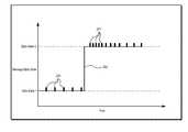
- FIG. 2illustrates an example of a timing diagram showing transmission of messages 200 , 204 by an IED consistent with embodiments disclosed herein.
- a messagemay include one or more control instructions, monitored system data, communications with other IEDs, monitored equipment and/or other network devices, and/or any other relevant communication, message, or data.
- a messagemay provide an indication as to a state and/or a data state (e.g., a measured state) of one or more components and/or conditions within an electrical power generation and delivery system. For example, a message may provide an indication of a measured current and/or voltage exceeding one or more thresholds.
- a certain state(e.g., “Data State 1”) may be associated with a measurement exceeding such a threshold, while another data state (e.g., “Data State 2”) may be associated with a measurement exceeding a different threshold.
- a message indicating a particular data statemay be utilized to determine whether the measured current and/or voltage exceed the one or more thresholds.
- a messagemay indicate a state of a component of an electric power generation and delivery system such as a state of a breaker (e.g., “open” or “closed”), a power storage device (e.g., “charged” or “depleted”), and/or the like.
- messages indicating a data statemay be embodied as GOOSE messages.
- a messagemay further indicate not only a particular data state, but also whether the message indicates a data state that is different than a data state indicated by one or more preceding message. That is, a message may include an indication that a data state associated with the message represents a data state change from a prior message. In certain embodiments, the prior message may be an immediately preceding message.
- data state change informationmay be indicated by a data state change indicator (DSCI) included in the message. For example, a DSCI included in a message may be set to “1” following a first data state change event.
- DSCIdata state change indicator
- the DSCImay be asserted in only a first message following a data state change event.
- the SCIBmay be asserted for a specified period of time or for a specified number of messages (e.g., a message stream).
- the SCIBmay be set to a different value upon a subsequent data state change event.
- an IEDmay transmit to subscribing (e.g., receiving) devices and/or receive from publishing (e.g., transmitting) devices messages 200 reflecting a particular data state (e.g., “Data State 1”) at periodic intervals at a first communication rate after a certain period in which the data state has remained constant (e.g., a message stream). For example, if a measured data state has not changed within the last 30 seconds, an IED may transmit messages 200 at periodic intervals at the first communication rate. In certain embodiments, this periodic interval may be relatively long, reflecting that a data state change has not recently occurred.
- a particular data statee.g., “Data State 1”
- this periodic intervalmay be relatively long, reflecting that a data state change has not recently occurred.
- Transmitting the same or similar data state messages periodically in a message streammay introduce a degree of redundancy, helping to ensure that subscribing devices receive messages during periods of network congestion and/or low network bandwidth conditions. Further, the continuous transmission may serve as an indicator that the transmitting device is continuing to operate as expected. Accordingly, the continuous stream of messages may be referred to as a “heartbeat”.
- the IEDmay publish and/or receive messages 204 reflecting the changed data state (e.g., “Data State 2”) at periodic intervals having a second communication rate.
- the second communication ratemay be faster than the first communication rate.
- the period between sequential messages 204may be shorter than the period between sequential messages 200 .
- the communication rate of the messages 204may progressively slow to reach, for example, a rate at or near the first communication rate.
- data state messagesmay be transmitted at a relatively fast rate immediately following a data state change event 202 that progressively slows as the data state change event 202 becomes older.
- the transmission ratemay decrease exponentially for a period of time following the data state change event 202 .
- Transmitting measured data state messages at a faster rate after a data state change event 202may ensure that devices subscribing to the communications (e.g., subscribing IEDs) are more likely to receive the messages indicating the data state change as closely as possible in time to the actual data state change event 202 . Transmitting redundant messages at a relatively fast rate, however, may introduce network congestion and/or bandwidth issues in some devices (e.g., communication switches, routers, radios, multiplexors, a real-time automation controller, IEDs, PLCs, and/or the like). Consistent with embodiments disclosed herein, a message buffer may be utilized in such devices to ensure that data state change messages are properly transmitted and/or routed under congested network or low network bandwidth conditions.
- devices subscribing to the communicationse.g., subscribing IEDs
- Transmitting redundant messages at a relatively fast ratemay introduce network congestion and/or bandwidth issues in some devices (e.g., communication switches, routers,
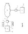
- FIG. 3Aillustrates IEDs 302 - 306 , 303 communicatively coupled with a network 300 via network switches 308 - 312 consistent with embodiments disclosed herein.
- IEDs 302 - 306 , 303may be configured to communicate via a network 300 using messages (e.g., GOOSE messages) that, in certain embodiments, may provide an indication as to a data state of one or more components and/or conditions within an electrical power generation and delivery system.
- messagese.g., GOOSE messages
- the network switches 308 - 312may be configured to receive messages from the network 300 and to transmit certain messages to an associated IED 302 - 306 , 303 .
- network switch 308may be configured to receive messages from the network 300 and to transmit certain of the received messages to IED 302 and/or IED 303 .
- a receiving IEDe.g., IED 302 and/or 303
- a network switchmay have a limited transfer rate that is lower than its receiving rate.
- a network switchmay have a 1 MB/second data transmission rate but a receiving rate that is substantially greater, thereby creating an asymmetry between inbound and outbound communication rates. If such a network switch includes a finite receiving and/or transmitting buffer and a substantial amount of data (e.g., a message stream) is received by such a network switch in a short period of time, the network switch may be unable to transmit received messages before the finite buffers become full and thus messages may be dropped or lost. In further circumstances, network devices and/or IEDs may have insufficient computing resources to process network traffic at “wire speed.”
- IEDs 302 - 306 , 303 and/or network switches 308 - 312may utilize a message receipt acknowledgement sent by a receiving and/or subscribing device to a transmitting and/or publishing device to manage the flow of messages (e.g., a message stream) transmitted from the transmitting and/or publishing device.
- a message receipt acknowledgementsent by a receiving and/or subscribing device to a transmitting and/or publishing device to manage the flow of messages (e.g., a message stream) transmitted from the transmitting and/or publishing device.
- FIG. 3Billustrates IEDs 302 - 306 , 305 communicatively coupled with a network 300 via network devices 308 , 312 and network radios 314 , 316 consistent with embodiments disclosed herein.
- Certain elements of the system illustrated in FIG. 3Bmay be similar to those illustrated in and described in reference to FIG. 3A and, accordingly, similar elements may be denoted with like numerals.
- FIG. 3Aalthough certain illustrated embodiments are discussed in reference to IEDs 302 - 306 , 305 network switches 308 , 312 and network radios 314 , 316 , further embodiments may be implemented in other suitable IEDs and/or network devices.
- IEDs 302 - 306 , 305may be configured to communicate via a network 300 using messages (e.g., GOOSE messages) that, in certain embodiments, may provide an indication as to a data state and/or data state change of one or more components and/or conditions within an electrical power generation and delivery system.
- the network switches 308 , 312 and/or and network radios 314 , 316may be configured to receive messages from the network 300 and to transmit certain messages to an associated IED 302 - 306 , 305 .
- network switch 308may be configured to receive messages from the network 300 and to transmit certain of the received messages to IED 302 and/or IED 305 .
- IED 304may communicate (e.g., exchange messages) with the network 300 via one or more network radios 314 , 316 or other similar network devices implementing a wireless communication methodology.
- a subscribing IEDmay include a finite receiving FIFO that may only store a predetermined number of messages, and thus may not be capable of storing certain messages if a significant number of messages are received in a relatively short period (e.g., during periods of high network message traffic).
- a network radioe.g., network radio 314
- network radio 314may have a 1 MB/second data transfer rate but a receiving rate that is substantially greater.
- a wireless communication channel between network radio 314 and network radio 316may have limited bandwidth. Messages may be lost due to these and other types of communication bottlenecks.
- network switches 308 , 312 and/or and network radios 314 , 316may utilize a message receipt acknowledgement sent by a receiving and/or subscribing device to a transmitting and/or publishing device to manage the flow of messages (e.g., a message stream) transmitted from the transmitting and/or publishing device.
- a message receipt acknowledgementsent by a receiving and/or subscribing device to a transmitting and/or publishing device to manage the flow of messages (e.g., a message stream) transmitted from the transmitting and/or publishing device.
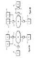
- FIG. 4Aillustrates communication between an IED 304 and network switch 310 consistent with embodiments disclosed herein.
- Certain elements of the system illustrated in FIG. 4Bmay be similar to those illustrated in and described in reference to FIG. 3A and FIG. 3B and, accordingly, similar elements may be denoted with like numerals.
- certain illustrated embodimentsare discussed in reference to IED 304 and network switch 310 , further embodiments may be implemented in other suitable IEDs and/or network devices.
- IED 304may be communicatively coupled to a network 300 via a network switch 310 .
- IED 304may be configured to communicate with the network 300 and/or network switch 310 using messages (e.g., GOOSE messages).
- the messagesmay provide an indication as to a data state and/or data state change of one or more components and/or conditions within an electrical power generation and delivery system.
- a publishing devicee.g., a publishing IED may transmit a particular message or similar copies of the message multiple times in a message stream.
- IED 304may transmit a message to network switch 310 .
- the messagemay be part of a message stream that includes multiple copies of the same and/or similar message. Transmitting the same or similar messages (e.g., data state messages) periodically in a message stream may introduce a degree of redundancy, helping to ensure that subscribing devices receive messages during periods of network congestion and/or low network bandwidth conditions. The increased network load associated with transmitting a particular message multiple times, however, may cause communication bottlenecks, thereby causing certain messages to be lost or delayed.
- a receiving and/or subscribing devicemay transmit a message receipt acknowledgement to a transmitting and/or publishing device indicating that a message (e.g., a particular message) was received.
- a messagee.g., a particular message
- network switch 310may transmit a message receipt acknowledgement to IED 304 indicating receipt of the message.
- the IED 304may stop transmitting further redundant copies of the message, thereby reducing the number of messages transmitted from IED 304 to the network switch 310 .
- the flow of messages between IED 304 and network switch 310may be better managed (e.g., during periods of high network message traffic), and the occurrence of lost or delayed messages and/or communication bottlenecks may be reduced.
- FIG. 4Billustrates communication between network switch 312 and an IED 306 consistent with embodiments disclosed herein. Certain elements of the system illustrated in FIG. 4B may be similar to those illustrated in and described in reference to FIGS. 3A-4A and, accordingly, similar elements may be denoted with like numerals. Further, although certain illustrated embodiments are discussed in reference to network switches 310 , 312 , further embodiments may be implemented in other suitable IEDs and/or network devices.
- Network switch 310may be communicatively coupled to a network switch 312 via network 300 .
- Network switch 310may be configured to communicate with the network 300 and/or network switch 312 using messages (e.g., GOOSE messages).
- the messagesmay provide an indication as to a data state and/or data state change of one or more components and/or conditions within an electrical power generation and delivery system.
- a publishing devicee.g., a publishing IED
- network switch 310may receive a message stream from IED 304 and may route messages of the message stream to network switch 312 via the network 300 .
- IED 304may transmit a message to network switch 310 that, as illustrated by arrow 330 , may be routed to network switch 312 via network 300 .
- the messagemay be part of a message stream that includes multiple copies of the same and/or similar message.
- a receiving and/or subscribing devicemay transmit a message receipt acknowledgement as illustrated by arrow 332 to a transmitting and/or publishing device indicating that a message (e.g., a particular message) was received.
- network switch 312may transmit a message receipt acknowledgement to network switch 310 indicating receipt of the message.
- network switch 310may stop transmitting further redundant copies of the message, thereby reducing the number of messages transmitted from network switch 310 to network switch 312 .
- the flow of messages between network switches 310 , 312may be better managed (e.g., during periods of high network message traffic), and the occurrence of lost or delayed messages and/or communication bottlenecks may be reduced.
- FIG. 4Cillustrates communication network switch 312 and IED 306 consistent with embodiments disclosed herein. Certain elements of the system illustrated in FIG. 4C may be similar to those illustrated in and described in reference to FIGS. 3A-4B and, accordingly, similar elements may be denoted with like numerals. Further, although certain illustrated embodiments are discussed in reference to network switch 312 and IED 306 , further embodiments may be implemented in other suitable IEDs and/or network devices.
- IED 306may be communicatively coupled to a network 300 via network switch 312 .
- IED 306may be configured to communicate with the network 300 and/or network switch 312 using messages (e.g., GOOSE messages).
- the messagesmay provide an indication as to a data state and/or data state change of one or more components and/or conditions within an electrical power generation and delivery system.
- a publishing devicee.g., a publishing IED
- network switch 312may receive a message stream originating from IED 304 via network 300 , and may route the message stream to IED 306 .
- IED 304may transmit a message to network switch 312 via network 300 .
- Network switch 312may be configured to route the message to IED 306 (e.g., as a subscribing device), as illustrated by arrow 330 .
- the messagemay be part of a message stream that includes multiple copies of the same and/or similar message.
- a receiving and/or subscribing devicemay transmit a message receipt acknowledgement to a transmitting and/or publishing device indicating that a message (e.g., a particular message) was received.
- IED 306may transmit a message receipt acknowledgement to network switch 312 indicating receipt of the message.
- network switch 312may stop transmitting further redundant copies of the message, thereby reducing the number of messages transmitted from network switch 312 to IED 306 .
- the flow of messages between network switch 312 and IED 306may be better managed (e.g., during periods of high network message traffic), and lost or delayed messages and/or communication bottlenecks may be reduced.
- FIG. 4Dillustrates communication between IEDs 304 , 306 and network devices (e.g., network switches 310 , 312 ) via a network 300 consistent with embodiments disclosed herein.
- network devicese.g., network switches 310 , 312
- Certain elements of the system illustrated in FIG. 4Dmay be similar to those illustrated in and described in reference to FIGS. 3A-4C and, accordingly, similar elements may be denoted with like numerals.
- FIG. 4Dillustrates communication between IEDs 304 , 306 and network devices (e.g., network switches 310 , 312 ) via a network 300 consistent with embodiments disclosed herein.
- Certain elements of the system illustrated in FIG. 4Dmay be similar to those illustrated in and described in reference to FIGS. 3A-4C and, accordingly, similar elements may be denoted with like numerals.
- FIG. 4Dillustrates communication between IEDs 304 , 306 and network devices (e.g., network switches 310 , 312 )
- IED 304may be communicatively coupled to the network 300 via network switch 310 .
- IED 306may be communicatively coupled to the network 300 via network switch 312 .
- IEDs 304 , 306 and network switches 310 , 312may be configured to communicate (e.g., via the network 300 ) using messages (e.g., GOOSE messages).
- the messagesmay provide an indication as to a data state and/or data state change of one or more components and/or conditions within an electrical power generation and delivery system.
- a transmitting or publishing devicemay transmit a particular message or similar copies of the message multiple times in a message stream.
- IED 304may transmit a message stream to network switch 310 .
- the message streammay include redundant copies of a particular message (e.g., a message including particular data state information).
- IED 304 and network switch 310may be capable of communicating without loss or delay of messages included in the message stream.
- the IED 304 and network switch 310may be capable communicating and/or processing message traffic at relatively high speeds and/or line rates, and thus may be able to transmit/receive and/or process all messages included in the message stream without loss or delay.
- Network switch 310may be configured to transmit the message stream to IED 306 via network 300 and network switch 312 . Accordingly, as illustrated, network switch 310 may be configured to communicate with network switch 312 via network 300 . Reduced bandwidth in a network path between network switch 310 and network switch 312 , device hardware limitations in network switches 310 , 312 and/or network 300 , and/or any other similar circumstance may cause a communication bottleneck between network switch 310 and network 312 during high network traffic conditions, potentially resulting in the loss or delay of messages included in a message stream. To ensure that messages are not lost or delayed between network switch 310 and network switch 312 , the network switches 310 , 312 may utilize a message receipt acknowledgement methodology consistent with embodiments disclosed herein.
- network switch 310may transmit a message to network switch 312 that, in certain embodiments, may be part of a message stream that includes multiple copies of the same and/or similar message. (e.g., the message stream transmitted by IED 304 to network switch 310 ).
- receiving network switch 312may transmit a message receipt acknowledgement to transmitting network switch 310 indicating that a message (e.g., a particular message of the message stream) was received.
- network switch 312may transmit a message receipt acknowledgement to network switch 310 indicating receipt of the message.
- network switch 312may stop transmitting further redundant copies of the message, thereby reducing the number of messages transmitted from network switch 310 to network switch 312 . In this manner, the flow of messages between network switch 310 and network switch 312 may be better managed (e.g., during periods of high network message traffic), and lost or delayed messages caused by communication bottlenecks may be reduced.
- Network switch 312may transmit the message to IED 306 (e.g., a subscribing device) as part of a message stream that includes multiple redundant copies of the message.
- IED 306e.g., a subscribing device
- network switch 312 and IED 306may be capable of communicating and/or processing message traffic at relatively high speeds and/or line rates, and thus may be able to transmit/receive and/or process all messages included in the message stream without loss or delay. Accordingly, network switch 312 and IED 306 may not need to implement the message receipt acknowledgement methodology disclosed herein to mitigate issues caused by communication bottlenecks during high network traffic.
- embodiments of the disclosed message receipt acknowledgement methodologymay be implemented in certain network and/or communication pathways that may experience communication bottlenecks (e.g., communications between network switches 310 , 312 ), and may not be implemented between other network and/or communication pathways that do not experience communication bottlenecks (e.g., communications between IED 304 and network switch 310 and network switch 312 and IED 306 ).
- Communication bottleneckse.g., communications between network switches 310 , 312
- Communication bottleneckse.g., communications between IED 304 and network switch 310 and network switch 312 and IED 306 .
- Selectively implementing the disclosed systems and methods where beneficial in an electric power generation and delivery systemmay allow for issues caused by local, regional, and/or isolated communication bottlenecks within a system topology to be reduced with minimal modifications to the components of the electric power generation and delivery system.
- embodiments of the disclosed message receipt acknowledgement systems and methodsmay allow for the generation of network information and/or data relating to communications in an electric power generation and delivery system. For example, latency of a particular network and/or communication pathway may be calculated based on a time between transmitting a message and receiving a message receipt acknowledgement. In certain embodiments, processing time at the receiving device may be accounted for in such a calculation to provide more accurate network and/or communication pathway latency information.
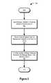
- FIG. 5illustrates a flow chart of a method 500 for exchanging messages between devices in an electric power generation and delivery system consistent with embodiments disclosed herein.
- the illustrated method 500may be performed by a network devices and/or IEDs that, in certain embodiments, may incorporate features of the systems illustrated in FIGS. 3A-4D .
- a message including an identifiermay be sent to a receiving device (e.g., a subscribing device) by a transmitting device that, in certain embodiments, may be a publishing device associated with the identifier.
- the messagemay be a GOOSE message and the identifier may be a subscription identifier.
- the messagemay further be a message of a message stream that includes multiple redundant copies of the same and/or similar message.
- a the transmitting devicemay receive a message receipt acknowledgement indicating that the transmitted message was received by the receiving device.
- the transmitting devicemay terminate sending further redundant copies of the transmitted message, thereby reducing the number of messages transmitted from the transmitting device to the receiving device. In this manner, the flow of messages between the transmitting device and the receiving device may be better managed (e.g., during periods of high network message traffic), and lost or delayed messages caused by communication bottlenecks may be reduced.
- FIG. 6illustrates a block diagram of a network device 600 for implementing certain embodiments of the systems and methods disclosed herein.
- the network device 600may be a network switch, modem, router, firewall, virtual private network server, and/or and any other suitable network device or system. Further embodiments may be implemented in an IED.
- the computer system 600may include a processor 602 , a random access memory (RAM) 604 , a communications interface 606 , a user interface 608 , and/or a non-transitory computer-readable storage medium 610 .
- RAMrandom access memory
- the processor 602 , RAM 604 , communications interface 606 , user interface 608 , and computer-readable storage medium 610may be communicatively coupled to each other via a common data bus 612 .
- the various components of the network device 600may be implemented using hardware, software, firmware, and/or any combination thereof.
- the user interface 608may be used to control certain features of the network device 600 (e.g., via any suitable interactive interface to a user, one or more visual or audible status indicators, and/or the like).
- the user interface 608may be integrated in the network device 600 or, alternatively, may be a user interface for a laptop or other similar device communicatively coupled with the computer system 600 .
- the user interface 608may be produced on a touch screen display.
- the communications interface 606may be any interface capable of communicating with other computer systems and/or other equipment (e.g., remote network equipment) communicatively coupled to computer system 600 .
- the processor 602may include one or more general purpose processors, application specific processors, microcontrollers, digital signal processors, FPGAs, or any other customizable or programmable processing device.
- the processor 602may be configured to execute computer-readable instructions stored on the non-transitory computer-readable storage medium 610 .
- the computer-readable instructionsmay be computer-executable functional modules.
- the computer-readable instructionsmay include one or more functional modules configured to implement all or part of the functionality of the systems and methods described above in reference to FIGS. 1-5 .
Landscapes
- Engineering & Computer Science (AREA)
- Computer Networks & Wireless Communication (AREA)
- Signal Processing (AREA)
- Remote Monitoring And Control Of Power-Distribution Networks (AREA)
- Health & Medical Sciences (AREA)
- Computing Systems (AREA)
- General Health & Medical Sciences (AREA)
- Medical Informatics (AREA)
Abstract
Description
Claims (15)
Priority Applications (1)
| Application Number | Priority Date | Filing Date | Title |
|---|---|---|---|
| US13/841,409US9270109B2 (en) | 2013-03-15 | 2013-03-15 | Exchange of messages between devices in an electrical power system |
Applications Claiming Priority (1)
| Application Number | Priority Date | Filing Date | Title |
|---|---|---|---|
| US13/841,409US9270109B2 (en) | 2013-03-15 | 2013-03-15 | Exchange of messages between devices in an electrical power system |
Publications (2)
| Publication Number | Publication Date |
|---|---|
| US20140280712A1 US20140280712A1 (en) | 2014-09-18 |
| US9270109B2true US9270109B2 (en) | 2016-02-23 |
Family
ID=51533548
Family Applications (1)
| Application Number | Title | Priority Date | Filing Date |
|---|---|---|---|
| US13/841,409Expired - Fee RelatedUS9270109B2 (en) | 2013-03-15 | 2013-03-15 | Exchange of messages between devices in an electrical power system |
Country Status (1)
| Country | Link |
|---|---|
| US (1) | US9270109B2 (en) |
Cited By (7)
| Publication number | Priority date | Publication date | Assignee | Title |
|---|---|---|---|---|
| US9620955B2 (en) | 2013-03-15 | 2017-04-11 | Schweitzer Engineering Laboratories, Inc. | Systems and methods for communicating data state change information between devices in an electrical power system |
| US9883567B2 (en) | 2014-08-11 | 2018-01-30 | RAB Lighting Inc. | Device indication and commissioning for a lighting control system |
| US9974150B2 (en) | 2014-08-11 | 2018-05-15 | RAB Lighting Inc. | Secure device rejoining for mesh network devices |
| US10039174B2 (en) | 2014-08-11 | 2018-07-31 | RAB Lighting Inc. | Systems and methods for acknowledging broadcast messages in a wireless lighting control network |
| US10531545B2 (en) | 2014-08-11 | 2020-01-07 | RAB Lighting Inc. | Commissioning a configurable user control device for a lighting control system |
| US10819727B2 (en) | 2018-10-15 | 2020-10-27 | Schweitzer Engineering Laboratories, Inc. | Detecting and deterring network attacks |
| US20230254228A1 (en)* | 2022-02-04 | 2023-08-10 | Schweitzer Engineering Laboratories, Inc. | Redundant generic object oriented substation event (goose) messages |
Families Citing this family (7)
| Publication number | Priority date | Publication date | Assignee | Title |
|---|---|---|---|---|
| US10728726B2 (en) | 2014-11-13 | 2020-07-28 | Abb Schweiz Ag | Sampled measurement data stream control |
| US11005616B2 (en) | 2015-12-22 | 2021-05-11 | Sony Corporation | Dynamic coverage enhancement |
| US10542456B2 (en)* | 2015-12-22 | 2020-01-21 | Sony Corporation | Dynamic coverage enhancement |
| US11418296B2 (en) | 2017-01-23 | 2022-08-16 | Sony Group Corporation | Coverage enhancement and fast acknowledgement |
| US11979024B2 (en)* | 2018-09-27 | 2024-05-07 | Siemens Canada Limited | Power distribution virtual networking |
| US10998716B2 (en)* | 2019-05-22 | 2021-05-04 | Eaton Intelligent Power Limited | Devices, systems and methods to monitor and report wiring status for zone selective interlocking cables |
| US20230253824A1 (en)* | 2022-02-04 | 2023-08-10 | Schweitzer Engineering Laboratories, Inc. | Redundant generic object oriented substation event (goose) messages |
Citations (107)
| Publication number | Priority date | Publication date | Assignee | Title |
|---|---|---|---|---|
| US4054949A (en)* | 1975-03-13 | 1977-10-18 | Fuji Electric Company Ltd. | Stagnation prevention apparatus in an information transmission system |
| US4535306A (en) | 1982-07-27 | 1985-08-13 | Pioneer Electronic Corporation | Phase-locked loop detecting circuit |
| US4546486A (en) | 1983-08-29 | 1985-10-08 | General Electric Company | Clock recovery arrangement |
| US4768178A (en) | 1987-02-24 | 1988-08-30 | Precision Standard Time, Inc. | High precision radio signal controlled continuously updated digital clock |
| US4808884A (en) | 1985-12-02 | 1989-02-28 | Western Digital Corporation | High order digital phase-locked loop system |
| US5103466A (en) | 1990-03-26 | 1992-04-07 | Intel Corporation | CMOS digital clock and data recovery circuit |
| US5235590A (en) | 1991-03-20 | 1993-08-10 | Fujitsu Limited | Read out apparatus for reading out information from magneto-optic disk |
| US5363377A (en) | 1992-04-09 | 1994-11-08 | U.S. Philips Corporation | Communications system and receiver for use therein which indicates time based on a selected time message signal from a central station |
| GB2278519A (en) | 1993-05-28 | 1994-11-30 | Motorola Israel Ltd | Time synchronisation between central and remote units |
| US5596263A (en) | 1993-12-01 | 1997-01-21 | Siemens Energy & Automation, Inc. | Electrical power distribution system apparatus-resident personality memory module |
| US5630757A (en)* | 1994-11-29 | 1997-05-20 | Net Game Limited | Real-time multi-user game communication system using existing cable television infrastructure |
| US5699367A (en)* | 1995-12-29 | 1997-12-16 | Telefonaktiebolaget Lm Ericsson | Concatenated error detection coding and packet numbering for hierarchical ARQ schemes |
| US5793869A (en) | 1996-10-11 | 1998-08-11 | Claflin, Jr.; Raymond E. | Method and apparatus for encoding and data compressing text information |
| WO2000016525A1 (en) | 1998-09-10 | 2000-03-23 | Silicon Image, Inc. | A system and method for sending and receiving data signals over a clock signal line |
| WO2000057527A1 (en) | 1999-03-24 | 2000-09-28 | General Electric Company | Fault data synchronization via peer-to-peer communications network |
| US20010023464A1 (en) | 2000-03-17 | 2001-09-20 | Bernhard Deck | Time synchronization of units in a system |
| US20020069299A1 (en) | 2000-12-01 | 2002-06-06 | Rosener Douglas K. | Method for synchronizing clocks |
| US20020080808A1 (en) | 2000-12-22 | 2002-06-27 | Leung Mun Keung | Dynamically modifying network resources for transferring packets in a vlan environment |
| US6456831B1 (en) | 1998-03-30 | 2002-09-24 | Nec Corporation | Amplitude change time activated phase locked controller in a selective call receiver |
| US6535925B1 (en) | 1999-11-09 | 2003-03-18 | Telefonaktiebolaget L M Ericsson (Publ) | Packet header compression using division remainders |
| US6577628B1 (en) | 1999-06-30 | 2003-06-10 | Sun Microsystems, Inc. | Providing quality of service (QoS) in a network environment in which client connections are maintained for limited periods of time |
| US6608841B1 (en) | 1999-12-30 | 2003-08-19 | Nokia Networks Oy | System and method for achieving robust IP/UDP/RTP header compression in the presence of unreliable networks |
| US20030195975A1 (en) | 1997-09-10 | 2003-10-16 | Papadopoulos A. Dean | Dual Ethernet stack for maximum speed access to a PLC |
| US20030204756A1 (en) | 1997-02-12 | 2003-10-30 | Ransom Douglas S. | Push communications architecture for intelligent electronic devices |
| US6678134B2 (en) | 2000-10-06 | 2004-01-13 | Kabushiki Kaisha Toshiba | Digital protective relay system |
| US6751209B1 (en) | 1999-02-17 | 2004-06-15 | Nokia Mobile Phones, Ltd. | Header compression in real time service |
| US6754210B1 (en) | 1998-06-11 | 2004-06-22 | Synchrodyne Networks, Inc. | Shared medium access scheduling with common time reference |
| US20040138834A1 (en) | 1994-12-30 | 2004-07-15 | Blackett Andrew W. | Communications architecture for intelligent electronic devices |
| US20040138786A1 (en) | 1994-12-30 | 2004-07-15 | Power Measurement, Ltd. | Method and system for master slave protocol communication in an intelligent electronic device |
| US20040148552A1 (en)* | 2002-03-14 | 2004-07-29 | Atsushi Matsumoto | Reception device and reception method |
| US20040196855A1 (en) | 2000-10-03 | 2004-10-07 | U4Ea Technologies Limited | Prioritizing data with flow control |
| US20040213214A1 (en)* | 2003-04-10 | 2004-10-28 | Samsung Electronics Co., Ltd. | Method for providing broadcast service over packet data channel in a wireless communication system |
| US6847691B2 (en) | 2000-02-14 | 2005-01-25 | Kabushiki Kaisha Toshiba | Time synchronizing system |
| US20050025105A1 (en) | 2003-07-30 | 2005-02-03 | Seon-Soo Rue | Apparatus and method for processing packets in wireless local area network access point |
| US6859742B2 (en) | 2001-07-12 | 2005-02-22 | Landis+Gyr Inc. | Redundant precision time keeping for utility meters |
| US20050085279A1 (en)* | 2003-09-30 | 2005-04-21 | Sharp Kabushiki Kaisha | Communication system, base station, terminal, communication device, communication management method, control program, and computer-readable recording medium containing the same |
| US6891441B2 (en) | 2002-11-15 | 2005-05-10 | Zoran Corporation | Edge synchronized phase-locked loop circuit |
| US20050160184A1 (en) | 2003-12-19 | 2005-07-21 | Rod Walsh | Method and system for header compression |
| US6937683B1 (en) | 2000-03-24 | 2005-08-30 | Cirronet Inc. | Compact digital timing recovery circuits, devices, systems and processes |
| US6947269B2 (en) | 2001-07-06 | 2005-09-20 | Schweitzer Engineering Laboratories, Inc. | Relay-to-relay direct communication system in an electric power system |
| WO2005088911A1 (en) | 2004-03-10 | 2005-09-22 | Matsushita Electric Industrial Co., Ltd. | Network relay service using source address-based priority conrol |
| US6973085B1 (en) | 2001-06-18 | 2005-12-06 | Advanced Micro Devices, Inc. | Using application headers to determine InfiniBand™ priorities in an InfiniBand™ network |
| US20060029105A1 (en) | 2004-08-03 | 2006-02-09 | General Electric Company | Fault recording and sequence of events recording device capable of recording communication-based signals related to electrical power systems |
| US20060123119A1 (en)* | 2004-12-08 | 2006-06-08 | Microsoft Corporation | Verifying and maintaining connection liveliness in a reliable messaging for web services environment |
| US20070002746A1 (en) | 2002-09-18 | 2007-01-04 | Broadcom Corporation | Per CoS memory partitioning |
| US20070058320A1 (en) | 2005-09-14 | 2007-03-15 | Schweitzer Engineering Laboratories, Inc. | Handheld communication tester and method for testing direct serial communication capability of an intelligent electronic device in a power system |
| US20070096942A1 (en) | 2005-10-28 | 2007-05-03 | Electro Industries/Gauge Tech. | Intelligent electronic device having an XML-based graphical interface |
| US20070127487A1 (en) | 2005-12-07 | 2007-06-07 | Electronics And Telecommunications Research Institute | Method for managing service bandwidth by customer port and EPON system using the same |
| US20070147415A1 (en) | 2005-12-23 | 2007-06-28 | General Electric Company | Intelligent electronic device with embedded multi-port data packet controller |
| US7239581B2 (en) | 2004-08-24 | 2007-07-03 | Symantec Operating Corporation | Systems and methods for synchronizing the internal clocks of a plurality of processor modules |
| US7272201B2 (en) | 2003-08-20 | 2007-09-18 | Schweitzer Engineering Laboratories, Inc. | System for synchronous sampling and time-of-day clocking using an encoded time signal |
| US7283568B2 (en) | 2001-09-11 | 2007-10-16 | Netiq Corporation | Methods, systems and computer program products for synchronizing clocks of nodes on a computer network |
| US20070252724A1 (en) | 2004-06-24 | 2007-11-01 | Donaghey Andrew P | Alert Device |
| US20070291780A1 (en) | 2006-06-16 | 2007-12-20 | Harris Corporation | System and methods for generic data transparent rules to support quality of service |
| US20080005484A1 (en) | 2006-06-30 | 2008-01-03 | Joshi Chandra P | Cache coherency controller management |
| US20080071482A1 (en) | 2006-09-19 | 2008-03-20 | Zweigle Gregary C | apparatus, method, and system for wide-area protection and control using power system data having a time component associated therewith |
| US20080068291A1 (en) | 2006-09-14 | 2008-03-20 | Springs Design, Inc. | Electronic devices having complementary dual displays |
| US20080101251A1 (en) | 2006-10-30 | 2008-05-01 | Casebolt David J | System, apparatus and method for mixed mode communication on a single network |
| US20080127210A1 (en) | 2006-07-21 | 2008-05-29 | Bosold Mark J | Method of configuring intelligent electronic devices to facilitate standardized communication messages among a plurality of ieds within a network |
| US20080188264A1 (en)* | 2004-05-07 | 2008-08-07 | Matsushita Electric Industrial Co., Ltd. | Base Station Apparatus |
| US20080189784A1 (en) | 2004-09-10 | 2008-08-07 | The Regents Of The University Of California | Method and Apparatus for Deep Packet Inspection |
| US20080192635A1 (en)* | 2005-03-29 | 2008-08-14 | Ntt Docomo, Inc. | Transmission Rate Control Method, Mobile Station and Radio Base Station |
| US20080219186A1 (en) | 2007-03-05 | 2008-09-11 | Grid Net, Inc. | Energy switch router |
| US20080235355A1 (en) | 2004-10-20 | 2008-09-25 | Electro Industries/Gauge Tech. | Intelligent Electronic Device for Receiving and Sending Data at High Speeds Over a Network |
| US7463467B2 (en) | 2001-07-06 | 2008-12-09 | Schweitzer Engineering Laboratories, Inc. | Relay-to-relay direct communication system and method in an electric power system |
| US20090052392A1 (en)* | 2005-02-15 | 2009-02-26 | Matsushita Electric Industrial Co., Ltd. | Retransmission control method, base station and mobile station |
| US20090141727A1 (en) | 2007-11-30 | 2009-06-04 | Brown Aaron C | Method and System for Infiniband Over Ethernet by Mapping an Ethernet Media Access Control (MAC) Address to an Infiniband Local Identifier (LID) |
| US20090160189A1 (en) | 2006-09-01 | 2009-06-25 | Keld Rasmussen | Priority System For Communication In A System Of At Least Two Distributed Wind Turbines |
| US20090180477A1 (en) | 2008-01-10 | 2009-07-16 | Shinichi Akahane | Relay device and relay device controlling method |
| US7571216B1 (en) | 2003-10-02 | 2009-08-04 | Cisco Technology, Inc. | Network device/CPU interface scheme |
| US20090254655A1 (en) | 2008-04-04 | 2009-10-08 | Beau Kidwell | Generation and Control of Network Events and Conversion to SCADA Protocol Data Types |
| US20090260083A1 (en) | 2003-05-21 | 2009-10-15 | Foundry Networks, Inc. | System and method for source ip anti-spoofing security |
| US7617408B2 (en) | 2006-02-13 | 2009-11-10 | Schweitzer Engineering Labortories, Inc. | System and method for providing accurate time generation in a computing device of a power system |
| US20090300165A1 (en)* | 2008-05-30 | 2009-12-03 | Square D Company | Message Monitor, Analyzer, Recorder and Viewer in a Publisher-Subscriber Environment |
| US20090319904A1 (en) | 2006-01-17 | 2009-12-24 | Reality Mobile Llc | System and Method for Remote Data Acquisition and Distribution |
| US20100020773A1 (en)* | 2008-07-23 | 2010-01-28 | Bruno Jechoux | Flow control techniques for co-localized wlan and bluetooth |
| US7664869B2 (en) | 1997-09-10 | 2010-02-16 | Schneider Automation Inc. | Web interface to a device and an electrical network control system |
| US20100054164A1 (en)* | 2008-08-28 | 2010-03-04 | Massachusetts Institute Of Technology | Random Linear Network Coding for Time Division Duplexing |
| US7701683B2 (en) | 2001-07-06 | 2010-04-20 | Schweitzer Engineering Laboratories, Inc. | Apparatus, system, and method for sharing output contacts across multiple relays |
| US20100104044A1 (en)* | 2007-03-23 | 2010-04-29 | Panasonic Corporation | Radio transmission device and radio reception device |
| US20100142560A1 (en) | 2007-07-05 | 2010-06-10 | Ceragon Networks Ltd. | Data packet header compression |
| US20100182952A1 (en)* | 2009-01-22 | 2010-07-22 | Samsung Electronics Co., Ltd. | RRC message transmission method in wireless communication system |
| US20100195763A1 (en) | 2001-07-06 | 2010-08-05 | Lee Tony J | Apparatus, system, and method for creating one or more slow-speed communications channels utilizing a real-time communication channel |
| US20100215004A1 (en)* | 2007-11-29 | 2010-08-26 | Hee Chul Yoo | Method for transmitting data using harq |
| US20100251134A1 (en) | 2007-09-14 | 2010-09-30 | Tomtom International B.V. | Communications apparatus, system and method of providing a user interface |
| US20100275086A1 (en)* | 2007-12-20 | 2010-10-28 | Telefonaktiebolaget L M Ericsson (Publ) | Prescheduled Retransmission for Initial Establishment |
| US20110022666A1 (en) | 2009-07-27 | 2011-01-27 | Sandisk Il Ltd. | Device identifier selection |
| US20110069718A1 (en) | 2009-09-18 | 2011-03-24 | Morris Robert E | Intelligent electronic device with segregated real-time ethernet |
| US20110069709A1 (en)* | 2009-09-18 | 2011-03-24 | Morris Robert E | Intelligent electronic device with segregated real-time ethernet |
| US8082367B2 (en) | 2009-07-23 | 2011-12-20 | Schneider Electric USA, Inc. | Differential time synchronization of intelligent electronic devices |
| US20120005326A1 (en) | 2010-07-02 | 2012-01-05 | Ryan Bradetich | Systems and methods for remote device management |
| US20120078555A1 (en) | 2005-01-27 | 2012-03-29 | Electro Industries/Gauge Tech | Intelligent Electronic Device and Method Thereof |
| US20120082048A1 (en) | 2010-10-05 | 2012-04-05 | Cisco Technology, Inc. | System and method for providing smart grid communications and management |
| US20120155458A1 (en)* | 2010-12-20 | 2012-06-21 | Brocade Communications Systems, Inc. | Repeated Lost Packet Retransmission in a TCP/IP Network |
| US20120195309A1 (en)* | 2011-01-27 | 2012-08-02 | Fujitsu Limited | Communication system, receiving device, relay device, reception method, and relay method |
| US20120215479A1 (en) | 2011-02-21 | 2012-08-23 | General Electric Company | System for testing intelligent electronic devices |
| US20120278421A1 (en) | 2011-04-27 | 2012-11-01 | Centec Networks (Suzhou) Co., Ltd. | Providing a data sample in a measurement and control system |
| US20130018521A1 (en) | 2010-08-24 | 2013-01-17 | Schweitzer Engineering Laboratories, Inc. | Systems and Methods for Blackout Protection |
| US20130039266A1 (en)* | 2011-08-08 | 2013-02-14 | Research In Motion Limited | System and method to increase link adaptation performance with multi-level feedback |
| US20130091258A1 (en) | 2011-10-07 | 2013-04-11 | Cisco Technology, Inc. | Communication network topology management based on an associated electric grid topology |
| US20130117755A1 (en) | 2011-11-08 | 2013-05-09 | Mckesson Financial Holdings | Apparatuses, systems, and methods for distributed workload serialization |
| US20130142336A1 (en)* | 2010-05-14 | 2013-06-06 | Siemens Aktiengesellschaft | Method of group key generation and management for generic object oriented substantiation events model |
| US20140025321A1 (en)* | 2007-04-03 | 2014-01-23 | Electro Industries/Gaugetech | System and method for performing data transfers in an intelligent electronic device |
| US20140195844A1 (en) | 2013-01-07 | 2014-07-10 | Abb Inc. | System and method for developing, deploying and implementing power system computer applications |
| US8793767B2 (en) | 2012-08-30 | 2014-07-29 | Schweitzer Engineering Laboratories Inc | Network access management via a secondary communication channel |
| US8819512B1 (en)* | 2008-01-19 | 2014-08-26 | Appex Networks Holding Limited | Method for detecting TCP packet losses and expediting packet retransmission |
| US20140269736A1 (en)* | 2013-03-15 | 2014-09-18 | Schweitzer Engineering Laboratories, Inc. | Transmission of Data Over a Low-Bandwidth Communication Channel |
- 2013
- 2013-03-15USUS13/841,409patent/US9270109B2/ennot_activeExpired - Fee Related
Patent Citations (110)
| Publication number | Priority date | Publication date | Assignee | Title |
|---|---|---|---|---|
| US4054949A (en)* | 1975-03-13 | 1977-10-18 | Fuji Electric Company Ltd. | Stagnation prevention apparatus in an information transmission system |
| US4535306A (en) | 1982-07-27 | 1985-08-13 | Pioneer Electronic Corporation | Phase-locked loop detecting circuit |
| US4546486A (en) | 1983-08-29 | 1985-10-08 | General Electric Company | Clock recovery arrangement |
| US4808884A (en) | 1985-12-02 | 1989-02-28 | Western Digital Corporation | High order digital phase-locked loop system |
| US4768178A (en) | 1987-02-24 | 1988-08-30 | Precision Standard Time, Inc. | High precision radio signal controlled continuously updated digital clock |
| US5103466A (en) | 1990-03-26 | 1992-04-07 | Intel Corporation | CMOS digital clock and data recovery circuit |
| US5235590A (en) | 1991-03-20 | 1993-08-10 | Fujitsu Limited | Read out apparatus for reading out information from magneto-optic disk |
| US5363377A (en) | 1992-04-09 | 1994-11-08 | U.S. Philips Corporation | Communications system and receiver for use therein which indicates time based on a selected time message signal from a central station |
| GB2278519A (en) | 1993-05-28 | 1994-11-30 | Motorola Israel Ltd | Time synchronisation between central and remote units |
| US5596263A (en) | 1993-12-01 | 1997-01-21 | Siemens Energy & Automation, Inc. | Electrical power distribution system apparatus-resident personality memory module |
| US5630757A (en)* | 1994-11-29 | 1997-05-20 | Net Game Limited | Real-time multi-user game communication system using existing cable television infrastructure |
| US20040138786A1 (en) | 1994-12-30 | 2004-07-15 | Power Measurement, Ltd. | Method and system for master slave protocol communication in an intelligent electronic device |
| US20040138834A1 (en) | 1994-12-30 | 2004-07-15 | Blackett Andrew W. | Communications architecture for intelligent electronic devices |
| US5699367A (en)* | 1995-12-29 | 1997-12-16 | Telefonaktiebolaget Lm Ericsson | Concatenated error detection coding and packet numbering for hierarchical ARQ schemes |
| US5793869A (en) | 1996-10-11 | 1998-08-11 | Claflin, Jr.; Raymond E. | Method and apparatus for encoding and data compressing text information |
| US20030204756A1 (en) | 1997-02-12 | 2003-10-30 | Ransom Douglas S. | Push communications architecture for intelligent electronic devices |
| US20030195975A1 (en) | 1997-09-10 | 2003-10-16 | Papadopoulos A. Dean | Dual Ethernet stack for maximum speed access to a PLC |
| US7664869B2 (en) | 1997-09-10 | 2010-02-16 | Schneider Automation Inc. | Web interface to a device and an electrical network control system |
| US6456831B1 (en) | 1998-03-30 | 2002-09-24 | Nec Corporation | Amplitude change time activated phase locked controller in a selective call receiver |
| US6754210B1 (en) | 1998-06-11 | 2004-06-22 | Synchrodyne Networks, Inc. | Shared medium access scheduling with common time reference |
| WO2000016525A1 (en) | 1998-09-10 | 2000-03-23 | Silicon Image, Inc. | A system and method for sending and receiving data signals over a clock signal line |
| US6751209B1 (en) | 1999-02-17 | 2004-06-15 | Nokia Mobile Phones, Ltd. | Header compression in real time service |
| WO2000057527A1 (en) | 1999-03-24 | 2000-09-28 | General Electric Company | Fault data synchronization via peer-to-peer communications network |
| US6577628B1 (en) | 1999-06-30 | 2003-06-10 | Sun Microsystems, Inc. | Providing quality of service (QoS) in a network environment in which client connections are maintained for limited periods of time |
| US6535925B1 (en) | 1999-11-09 | 2003-03-18 | Telefonaktiebolaget L M Ericsson (Publ) | Packet header compression using division remainders |
| US6608841B1 (en) | 1999-12-30 | 2003-08-19 | Nokia Networks Oy | System and method for achieving robust IP/UDP/RTP header compression in the presence of unreliable networks |
| US6847691B2 (en) | 2000-02-14 | 2005-01-25 | Kabushiki Kaisha Toshiba | Time synchronizing system |
| US20010023464A1 (en) | 2000-03-17 | 2001-09-20 | Bernhard Deck | Time synchronization of units in a system |
| US6937683B1 (en) | 2000-03-24 | 2005-08-30 | Cirronet Inc. | Compact digital timing recovery circuits, devices, systems and processes |
| US20040196855A1 (en) | 2000-10-03 | 2004-10-07 | U4Ea Technologies Limited | Prioritizing data with flow control |
| US6678134B2 (en) | 2000-10-06 | 2004-01-13 | Kabushiki Kaisha Toshiba | Digital protective relay system |
| US20020069299A1 (en) | 2000-12-01 | 2002-06-06 | Rosener Douglas K. | Method for synchronizing clocks |
| US20020080808A1 (en) | 2000-12-22 | 2002-06-27 | Leung Mun Keung | Dynamically modifying network resources for transferring packets in a vlan environment |
| US6973085B1 (en) | 2001-06-18 | 2005-12-06 | Advanced Micro Devices, Inc. | Using application headers to determine InfiniBand™ priorities in an InfiniBand™ network |
| US7701683B2 (en) | 2001-07-06 | 2010-04-20 | Schweitzer Engineering Laboratories, Inc. | Apparatus, system, and method for sharing output contacts across multiple relays |
| US7463467B2 (en) | 2001-07-06 | 2008-12-09 | Schweitzer Engineering Laboratories, Inc. | Relay-to-relay direct communication system and method in an electric power system |
| US6947269B2 (en) | 2001-07-06 | 2005-09-20 | Schweitzer Engineering Laboratories, Inc. | Relay-to-relay direct communication system in an electric power system |
| US20100195763A1 (en) | 2001-07-06 | 2010-08-05 | Lee Tony J | Apparatus, system, and method for creating one or more slow-speed communications channels utilizing a real-time communication channel |
| US6859742B2 (en) | 2001-07-12 | 2005-02-22 | Landis+Gyr Inc. | Redundant precision time keeping for utility meters |
| US7283568B2 (en) | 2001-09-11 | 2007-10-16 | Netiq Corporation | Methods, systems and computer program products for synchronizing clocks of nodes on a computer network |
| US20040148552A1 (en)* | 2002-03-14 | 2004-07-29 | Atsushi Matsumoto | Reception device and reception method |
| US20070002746A1 (en) | 2002-09-18 | 2007-01-04 | Broadcom Corporation | Per CoS memory partitioning |
| US6891441B2 (en) | 2002-11-15 | 2005-05-10 | Zoran Corporation | Edge synchronized phase-locked loop circuit |
| US20040213214A1 (en)* | 2003-04-10 | 2004-10-28 | Samsung Electronics Co., Ltd. | Method for providing broadcast service over packet data channel in a wireless communication system |
| US20090260083A1 (en) | 2003-05-21 | 2009-10-15 | Foundry Networks, Inc. | System and method for source ip anti-spoofing security |
| US20050025105A1 (en) | 2003-07-30 | 2005-02-03 | Seon-Soo Rue | Apparatus and method for processing packets in wireless local area network access point |
| US7272201B2 (en) | 2003-08-20 | 2007-09-18 | Schweitzer Engineering Laboratories, Inc. | System for synchronous sampling and time-of-day clocking using an encoded time signal |
| US20050085279A1 (en)* | 2003-09-30 | 2005-04-21 | Sharp Kabushiki Kaisha | Communication system, base station, terminal, communication device, communication management method, control program, and computer-readable recording medium containing the same |
| US7571216B1 (en) | 2003-10-02 | 2009-08-04 | Cisco Technology, Inc. | Network device/CPU interface scheme |
| US20050160184A1 (en) | 2003-12-19 | 2005-07-21 | Rod Walsh | Method and system for header compression |
| WO2005088911A1 (en) | 2004-03-10 | 2005-09-22 | Matsushita Electric Industrial Co., Ltd. | Network relay service using source address-based priority conrol |
| US20080188264A1 (en)* | 2004-05-07 | 2008-08-07 | Matsushita Electric Industrial Co., Ltd. | Base Station Apparatus |
| US20070252724A1 (en) | 2004-06-24 | 2007-11-01 | Donaghey Andrew P | Alert Device |
| US20060029105A1 (en) | 2004-08-03 | 2006-02-09 | General Electric Company | Fault recording and sequence of events recording device capable of recording communication-based signals related to electrical power systems |
| US7239581B2 (en) | 2004-08-24 | 2007-07-03 | Symantec Operating Corporation | Systems and methods for synchronizing the internal clocks of a plurality of processor modules |
| US20080189784A1 (en) | 2004-09-10 | 2008-08-07 | The Regents Of The University Of California | Method and Apparatus for Deep Packet Inspection |
| US20080235355A1 (en) | 2004-10-20 | 2008-09-25 | Electro Industries/Gauge Tech. | Intelligent Electronic Device for Receiving and Sending Data at High Speeds Over a Network |
| US20060123119A1 (en)* | 2004-12-08 | 2006-06-08 | Microsoft Corporation | Verifying and maintaining connection liveliness in a reliable messaging for web services environment |
| US20120078555A1 (en) | 2005-01-27 | 2012-03-29 | Electro Industries/Gauge Tech | Intelligent Electronic Device and Method Thereof |
| US20090052392A1 (en)* | 2005-02-15 | 2009-02-26 | Matsushita Electric Industrial Co., Ltd. | Retransmission control method, base station and mobile station |
| US20080192635A1 (en)* | 2005-03-29 | 2008-08-14 | Ntt Docomo, Inc. | Transmission Rate Control Method, Mobile Station and Radio Base Station |
| US20070058320A1 (en) | 2005-09-14 | 2007-03-15 | Schweitzer Engineering Laboratories, Inc. | Handheld communication tester and method for testing direct serial communication capability of an intelligent electronic device in a power system |
| US20070096942A1 (en) | 2005-10-28 | 2007-05-03 | Electro Industries/Gauge Tech. | Intelligent electronic device having an XML-based graphical interface |
| US20070127487A1 (en) | 2005-12-07 | 2007-06-07 | Electronics And Telecommunications Research Institute | Method for managing service bandwidth by customer port and EPON system using the same |
| US20070147415A1 (en) | 2005-12-23 | 2007-06-28 | General Electric Company | Intelligent electronic device with embedded multi-port data packet controller |
| US20090319904A1 (en) | 2006-01-17 | 2009-12-24 | Reality Mobile Llc | System and Method for Remote Data Acquisition and Distribution |
| US7617408B2 (en) | 2006-02-13 | 2009-11-10 | Schweitzer Engineering Labortories, Inc. | System and method for providing accurate time generation in a computing device of a power system |
| US20070291780A1 (en) | 2006-06-16 | 2007-12-20 | Harris Corporation | System and methods for generic data transparent rules to support quality of service |
| US20080005484A1 (en) | 2006-06-30 | 2008-01-03 | Joshi Chandra P | Cache coherency controller management |
| US20080127210A1 (en) | 2006-07-21 | 2008-05-29 | Bosold Mark J | Method of configuring intelligent electronic devices to facilitate standardized communication messages among a plurality of ieds within a network |
| US20090160189A1 (en) | 2006-09-01 | 2009-06-25 | Keld Rasmussen | Priority System For Communication In A System Of At Least Two Distributed Wind Turbines |
| US20080068291A1 (en) | 2006-09-14 | 2008-03-20 | Springs Design, Inc. | Electronic devices having complementary dual displays |
| US20080071482A1 (en) | 2006-09-19 | 2008-03-20 | Zweigle Gregary C | apparatus, method, and system for wide-area protection and control using power system data having a time component associated therewith |
| US20080101251A1 (en) | 2006-10-30 | 2008-05-01 | Casebolt David J | System, apparatus and method for mixed mode communication on a single network |
| US20080219186A1 (en) | 2007-03-05 | 2008-09-11 | Grid Net, Inc. | Energy switch router |
| US20100104044A1 (en)* | 2007-03-23 | 2010-04-29 | Panasonic Corporation | Radio transmission device and radio reception device |
| US20140025321A1 (en)* | 2007-04-03 | 2014-01-23 | Electro Industries/Gaugetech | System and method for performing data transfers in an intelligent electronic device |
| US20100142560A1 (en) | 2007-07-05 | 2010-06-10 | Ceragon Networks Ltd. | Data packet header compression |
| US20100251134A1 (en) | 2007-09-14 | 2010-09-30 | Tomtom International B.V. | Communications apparatus, system and method of providing a user interface |
| US20100215004A1 (en)* | 2007-11-29 | 2010-08-26 | Hee Chul Yoo | Method for transmitting data using harq |
| US20090141727A1 (en) | 2007-11-30 | 2009-06-04 | Brown Aaron C | Method and System for Infiniband Over Ethernet by Mapping an Ethernet Media Access Control (MAC) Address to an Infiniband Local Identifier (LID) |
| US20100275086A1 (en)* | 2007-12-20 | 2010-10-28 | Telefonaktiebolaget L M Ericsson (Publ) | Prescheduled Retransmission for Initial Establishment |
| US20090180477A1 (en) | 2008-01-10 | 2009-07-16 | Shinichi Akahane | Relay device and relay device controlling method |
| US8819512B1 (en)* | 2008-01-19 | 2014-08-26 | Appex Networks Holding Limited | Method for detecting TCP packet losses and expediting packet retransmission |
| US20090254655A1 (en) | 2008-04-04 | 2009-10-08 | Beau Kidwell | Generation and Control of Network Events and Conversion to SCADA Protocol Data Types |
| US20090300165A1 (en)* | 2008-05-30 | 2009-12-03 | Square D Company | Message Monitor, Analyzer, Recorder and Viewer in a Publisher-Subscriber Environment |
| US20100020773A1 (en)* | 2008-07-23 | 2010-01-28 | Bruno Jechoux | Flow control techniques for co-localized wlan and bluetooth |
| US20100054164A1 (en)* | 2008-08-28 | 2010-03-04 | Massachusetts Institute Of Technology | Random Linear Network Coding for Time Division Duplexing |
| US20100182952A1 (en)* | 2009-01-22 | 2010-07-22 | Samsung Electronics Co., Ltd. | RRC message transmission method in wireless communication system |
| US8082367B2 (en) | 2009-07-23 | 2011-12-20 | Schneider Electric USA, Inc. | Differential time synchronization of intelligent electronic devices |
| US20110022666A1 (en) | 2009-07-27 | 2011-01-27 | Sandisk Il Ltd. | Device identifier selection |
| US20110069709A1 (en)* | 2009-09-18 | 2011-03-24 | Morris Robert E | Intelligent electronic device with segregated real-time ethernet |
| US20110069718A1 (en) | 2009-09-18 | 2011-03-24 | Morris Robert E | Intelligent electronic device with segregated real-time ethernet |
| US8351433B2 (en) | 2009-09-18 | 2013-01-08 | Schweitzer Engineering Laboratories Inc | Intelligent electronic device with segregated real-time ethernet |
| US20130142336A1 (en)* | 2010-05-14 | 2013-06-06 | Siemens Aktiengesellschaft | Method of group key generation and management for generic object oriented substantiation events model |
| US8578012B2 (en) | 2010-07-02 | 2013-11-05 | Schweitzer Engineering Laboratories Inc | Local intelligent electronic device (IED) rendering templates over limited bandwidth communication link to manage remote IED |
| US20120005326A1 (en) | 2010-07-02 | 2012-01-05 | Ryan Bradetich | Systems and methods for remote device management |
| US20130018521A1 (en) | 2010-08-24 | 2013-01-17 | Schweitzer Engineering Laboratories, Inc. | Systems and Methods for Blackout Protection |
| US20120082048A1 (en) | 2010-10-05 | 2012-04-05 | Cisco Technology, Inc. | System and method for providing smart grid communications and management |
| US20120155458A1 (en)* | 2010-12-20 | 2012-06-21 | Brocade Communications Systems, Inc. | Repeated Lost Packet Retransmission in a TCP/IP Network |
| US20120195309A1 (en)* | 2011-01-27 | 2012-08-02 | Fujitsu Limited | Communication system, receiving device, relay device, reception method, and relay method |
| US20120215479A1 (en) | 2011-02-21 | 2012-08-23 | General Electric Company | System for testing intelligent electronic devices |
| US20120278421A1 (en) | 2011-04-27 | 2012-11-01 | Centec Networks (Suzhou) Co., Ltd. | Providing a data sample in a measurement and control system |
| US20130039266A1 (en)* | 2011-08-08 | 2013-02-14 | Research In Motion Limited | System and method to increase link adaptation performance with multi-level feedback |
| US20130091258A1 (en) | 2011-10-07 | 2013-04-11 | Cisco Technology, Inc. | Communication network topology management based on an associated electric grid topology |
| US20130117755A1 (en) | 2011-11-08 | 2013-05-09 | Mckesson Financial Holdings | Apparatuses, systems, and methods for distributed workload serialization |
| US8793767B2 (en) | 2012-08-30 | 2014-07-29 | Schweitzer Engineering Laboratories Inc | Network access management via a secondary communication channel |
| US20140195844A1 (en) | 2013-01-07 | 2014-07-10 | Abb Inc. | System and method for developing, deploying and implementing power system computer applications |
| US20140269736A1 (en)* | 2013-03-15 | 2014-09-18 | Schweitzer Engineering Laboratories, Inc. | Transmission of Data Over a Low-Bandwidth Communication Channel |
| US9065763B2 (en) | 2013-03-15 | 2015-06-23 | Schweitzer Engineering Laboratories, Inc. | Transmission of data over a low-bandwidth communication channel |
Non-Patent Citations (19)
| Title |
|---|
| Bill Lichtensteiger, Branko Bjelajac, Christian Muller, Christian Wietfeld. "RF Mesh Systems for Smart Metering: System Architecture and Performance", Smart Grid Communications, IEEE, Oct. 2010. |
| Brantley, Robert, Jacobus Theron, and Eric Udren. "The Application of IEC® 61850 to Replace Auxiliary Devices Including Lockout Relays." 60th Annual Georgia Tech Protective Relaying Conference May. 2006.* |
| D. Mills, Simple Network Time Protocol (SNTP) Version 4 for IPv4, IPv6, and OSI, Network Working Group Request for Comments: 4330, Jan. 2006. |
| D.L. Mills, Experiments in Network Clock Synchronization, Network Working Group Request for Comments: 957, Sep. 1985. |
| Daqing Hou, Dave Dolezilek, IEC 61850-What It Can and Cannot Offer to Traditional Protection Schemes, Sep. 2008. |
| Fateri, Sina, et al. "Design and Analysis of Multicast-Based Publisher/Subscriber Models over Wireless Platforms for Smart Grid Communications." Trust, Security and Privacy in Computing and Communications (TrustCom), 2012 IEEE 11th International Conference on. IEEE, 2012.* |
| James W. Rice, Sam Fulford, and Nicholas C. Seeley, Improved Service Reliability for Rural Electric Customers-Innovative Auto-Restoration Following Loss of Primary Source Interconnection, Sep. 2006. |
| Maheswaran, O., A. Kavitha Lakshmi, and R. Malarvizhi. "Guidelines for specification and evaluation of substation automation projects based on IEC 61850." CIGRE India Journal 1.1 (2012): 30-35.* |
| Nicholas C. Seeley, Automation at Protection Speeds: IEC 61850 GOOSE Messaging as a Reliable, High-Speed Alternative to Serial Communications, Feb. 2008. |
| Ozansoy, Cagil R., Aladin Zayegh, and Akhtar Kalam. "The real-time publisher/subscriber communication model for distributed substation systems."Power Delivery, IEEE Transactions on 22.3 (2007): 1411-1423.* |
| PCT/US2010/049169 Patent Cooperation Treaty Notification of Transmittal of the International Search Report and the Written Opinion, International Search Report, and Written Opinion, Nov. 5, 2010. |
| PCT/US2011/039498 Patent Cooperation Treaty, International Search Report and Written Opinion of the International Searching Authority, Oct. 21, 2011. |
| PCT/US2014/016955 Patent Cooperation Treaty, International Search Report and Written Opinion of the International Searching Authority, Jun. 5, 2014. |
| PCT/US2014/023169 Patent Cooperation Treaty, International Search Report and Written Opinion of the International Searching Authority, Aug. 19, 2014. |
| Roy Moxley, Ken Fodero, and Hector J. Altuve, Updated Transmission Line Protection Communications, IEEE, Oct. 2008. |
| S. Ward, W. Higinbotham, E. Duvelson, Inside the Cloud-Network Communications Basics for the Relay Engineer, 34th Annual Western Protective Relay Conference, Oct. 2007. |
| Smith, T., J. Vico, and Craig Wester. "Advanced distribution reclosing using wireless communications." Rural Electric Power Conference (REPC), 2011 IEEE. IEEE, 2011.* |
| W. Kleinebreg, ABB Switzerland Ltd., Hirschmann Automation & Control GmbH, IEC 61850 Modeling of Switches, Dec. 2009. |
| Xyngi, I., and M. Popov. "IEC61850 overview-where protection meets communication." (2010): 46-46.* |
Cited By (14)
| Publication number | Priority date | Publication date | Assignee | Title |
|---|---|---|---|---|
| US9620955B2 (en) | 2013-03-15 | 2017-04-11 | Schweitzer Engineering Laboratories, Inc. | Systems and methods for communicating data state change information between devices in an electrical power system |
| US10531545B2 (en) | 2014-08-11 | 2020-01-07 | RAB Lighting Inc. | Commissioning a configurable user control device for a lighting control system |
| US9974150B2 (en) | 2014-08-11 | 2018-05-15 | RAB Lighting Inc. | Secure device rejoining for mesh network devices |
| US10039174B2 (en) | 2014-08-11 | 2018-07-31 | RAB Lighting Inc. | Systems and methods for acknowledging broadcast messages in a wireless lighting control network |
| US10085328B2 (en) | 2014-08-11 | 2018-09-25 | RAB Lighting Inc. | Wireless lighting control systems and methods |
| US10219356B2 (en) | 2014-08-11 | 2019-02-26 | RAB Lighting Inc. | Automated commissioning for lighting control systems |
| US9883567B2 (en) | 2014-08-11 | 2018-01-30 | RAB Lighting Inc. | Device indication and commissioning for a lighting control system |
| US10855488B2 (en) | 2014-08-11 | 2020-12-01 | RAB Lighting Inc. | Scheduled automation associations for a lighting control system |
| US11398924B2 (en) | 2014-08-11 | 2022-07-26 | RAB Lighting Inc. | Wireless lighting controller for a lighting control system |
| US11722332B2 (en) | 2014-08-11 | 2023-08-08 | RAB Lighting Inc. | Wireless lighting controller with abnormal event detection |
| US12068881B2 (en) | 2014-08-11 | 2024-08-20 | RAB Lighting Inc. | Wireless lighting control system with independent site operation |
| US10819727B2 (en) | 2018-10-15 | 2020-10-27 | Schweitzer Engineering Laboratories, Inc. | Detecting and deterring network attacks |
| US20230254228A1 (en)* | 2022-02-04 | 2023-08-10 | Schweitzer Engineering Laboratories, Inc. | Redundant generic object oriented substation event (goose) messages |
| US11831529B2 (en)* | 2022-02-04 | 2023-11-28 | Schweitzer Engineering Laboratories, Inc. | Redundant generic object oriented substation event (GOOSE) messages |
Also Published As
| Publication number | Publication date |
|---|---|
| US20140280712A1 (en) | 2014-09-18 |
Similar Documents
| Publication | Publication Date | Title |
|---|---|---|
| US9270109B2 (en) | Exchange of messages between devices in an electrical power system | |
| US9620955B2 (en) | Systems and methods for communicating data state change information between devices in an electrical power system | |
| US20140282021A1 (en) | Visualization of Communication Between Devices in an Electric Power System | |
| US9363200B2 (en) | Transmission of data over a low-bandwidth communication channel | |
| US10333301B2 (en) | Transient simulation modeling for dynamic remedial action schemes using real-time protection setting updates | |
| US9257833B2 (en) | Adaptive topology assisted protection and control of electric power delivery systems | |
| US9383735B2 (en) | Distributed coordinated electric power delivery control system using component models | |
| US20140280714A1 (en) | Mixed-Mode Communication Between Devices in an Electrical Power System | |
| US20140280672A1 (en) | Systems and Methods for Managing Communication Between Devices in an Electrical Power System | |
| US9705305B2 (en) | Resilient communication for an electric power delivery system | |
| US20140280713A1 (en) | Proxy Communication Between Devices in an Electrical Power System | |
| US9300591B2 (en) | Network device | |
| US20140225626A1 (en) | Systems and Methods to Detect Poorly Damped Oscillation Modes | |
| US20190207694A1 (en) | Systems and methods for time-synchronized communication | |
| Teoh et al. | A centralized protection and control system using a well proven transmission class protection relay | |
| US20170111904A1 (en) | Deterministic transmission of communication packets of multiple protocols on a network | |
| Espinoza et al. | Wide-area synchrophasors protect and control Central America's power system stability |
Legal Events
| Date | Code | Title | Description |
|---|---|---|---|
| AS | Assignment | Owner name:SCHWEITZER ENGINEERING LABORATORIES, INC., WASHING Free format text:ASSIGNMENT OF ASSIGNORS INTEREST;ASSIGNORS:DOLEZILEK, DAVID J.;DAY, BENJAMIN S.;GAMMEL, DENNIS;AND OTHERS;SIGNING DATES FROM 20130314 TO 20130315;REEL/FRAME:030021/0606 | |
| ZAAA | Notice of allowance and fees due | Free format text:ORIGINAL CODE: NOA | |
| ZAAB | Notice of allowance mailed | Free format text:ORIGINAL CODE: MN/=. | |
| STCF | Information on status: patent grant | Free format text:PATENTED CASE | |
| AS | Assignment | Owner name:CITIBANK, N.A., AS ADMINISTRATIVE AGENT, TEXAS Free format text:NOTICE OF GRANT OF SECURITY INTEREST IN PATENTS;ASSIGNOR:SCHWEITZER ENGINEERING LABORATORIES, INC.;REEL/FRAME:047231/0253 Effective date:20180601 | |
| MAFP | Maintenance fee payment | Free format text:PAYMENT OF MAINTENANCE FEE, 4TH YEAR, LARGE ENTITY (ORIGINAL EVENT CODE: M1551); ENTITY STATUS OF PATENT OWNER: LARGE ENTITY Year of fee payment:4 | |
| FEPP | Fee payment procedure | Free format text:MAINTENANCE FEE REMINDER MAILED (ORIGINAL EVENT CODE: REM.); ENTITY STATUS OF PATENT OWNER: LARGE ENTITY | |
| LAPS | Lapse for failure to pay maintenance fees | Free format text:PATENT EXPIRED FOR FAILURE TO PAY MAINTENANCE FEES (ORIGINAL EVENT CODE: EXP.); ENTITY STATUS OF PATENT OWNER: LARGE ENTITY | |
| STCH | Information on status: patent discontinuation | Free format text:PATENT EXPIRED DUE TO NONPAYMENT OF MAINTENANCE FEES UNDER 37 CFR 1.362 | |
| FP | Lapsed due to failure to pay maintenance fee | Effective date:20240223 |