US9269378B2 - Stray field shielding for perpendicular magnetic recording write head - Google Patents
Stray field shielding for perpendicular magnetic recording write headDownload PDFInfo
- Publication number
- US9269378B2 US9269378B2US14/136,830US201314136830AUS9269378B2US 9269378 B2US9269378 B2US 9269378B2US 201314136830 AUS201314136830 AUS 201314136830AUS 9269378 B2US9269378 B2US 9269378B2
- Authority
- US
- United States
- Prior art keywords
- shield
- magnetic
- head
- nonmagnetic material
- pole
- Prior art date
- Legal status (The legal status is an assumption and is not a legal conclusion. Google has not performed a legal analysis and makes no representation as to the accuracy of the status listed.)
- Expired - Fee Related
Links
- 239000000463materialSubstances0.000claimsabstractdescription60
- 239000000696magnetic materialSubstances0.000claimsdescription32
- 230000004907fluxEffects0.000abstractdescription17
- 238000004519manufacturing processMethods0.000abstractdescription4
- 230000015556catabolic processEffects0.000abstractdescription3
- 230000003247decreasing effectEffects0.000abstractdescription3
- 238000006731degradation reactionMethods0.000abstractdescription3
- 239000010410layerSubstances0.000description12
- PNEYBMLMFCGWSK-UHFFFAOYSA-Naluminium oxideInorganic materials[O-2].[O-2].[O-2].[Al+3].[Al+3]PNEYBMLMFCGWSK-UHFFFAOYSA-N0.000description6
- 230000002829reductive effectEffects0.000description4
- 230000008901benefitEffects0.000description3
- 239000000725suspensionSubstances0.000description3
- 229910000531Co alloyInorganic materials0.000description2
- 229910000640Fe alloyInorganic materials0.000description2
- 229910000990Ni alloyInorganic materials0.000description2
- 229910004158TaOInorganic materials0.000description2
- VNNRSPGTAMTISX-UHFFFAOYSA-Nchromium nickelChemical compound[Cr].[Ni]VNNRSPGTAMTISX-UHFFFAOYSA-N0.000description2
- 229910052593corundumInorganic materials0.000description2
- 230000008878couplingEffects0.000description2
- 238000010168coupling processMethods0.000description2
- 238000005859coupling reactionMethods0.000description2
- 230000000670limiting effectEffects0.000description2
- 238000000034methodMethods0.000description2
- 229910003465moissaniteInorganic materials0.000description2
- 229910001120nichromeInorganic materials0.000description2
- 230000036961partial effectEffects0.000description2
- 230000008569processEffects0.000description2
- 229910052703rhodiumInorganic materials0.000description2
- 229910052707rutheniumInorganic materials0.000description2
- 229910010271silicon carbideInorganic materials0.000description2
- 230000007704transitionEffects0.000description2
- 229910001845yogo sapphireInorganic materials0.000description2
- 238000004590computer programMethods0.000description1
- 239000012141concentrateSubstances0.000description1
- 239000002355dual-layerSubstances0.000description1
- 230000000694effectsEffects0.000description1
- 230000002452interceptive effectEffects0.000description1
- 230000005415magnetizationEffects0.000description1
- 230000000717retained effectEffects0.000description1
- 238000000926separation methodMethods0.000description1
- 239000007787solidSubstances0.000description1
- 239000000758substrateSubstances0.000description1
- 239000010409thin filmSubstances0.000description1
- 230000005641tunnelingEffects0.000description1
Images


Classifications
- G—PHYSICS
- G11—INFORMATION STORAGE
- G11B—INFORMATION STORAGE BASED ON RELATIVE MOVEMENT BETWEEN RECORD CARRIER AND TRANSDUCER
- G11B5/00—Recording by magnetisation or demagnetisation of a record carrier; Reproducing by magnetic means; Record carriers therefor
- G11B5/10—Structure or manufacture of housings or shields for heads
- G11B5/11—Shielding of head against electric or magnetic fields
- G—PHYSICS
- G11—INFORMATION STORAGE
- G11B—INFORMATION STORAGE BASED ON RELATIVE MOVEMENT BETWEEN RECORD CARRIER AND TRANSDUCER
- G11B5/00—Recording by magnetisation or demagnetisation of a record carrier; Reproducing by magnetic means; Record carriers therefor
- G11B5/127—Structure or manufacture of heads, e.g. inductive
- G11B5/1278—Structure or manufacture of heads, e.g. inductive specially adapted for magnetisations perpendicular to the surface of the record carrier
- G—PHYSICS
- G11—INFORMATION STORAGE
- G11B—INFORMATION STORAGE BASED ON RELATIVE MOVEMENT BETWEEN RECORD CARRIER AND TRANSDUCER
- G11B5/00—Recording by magnetisation or demagnetisation of a record carrier; Reproducing by magnetic means; Record carriers therefor
- G11B5/127—Structure or manufacture of heads, e.g. inductive
- G11B5/31—Structure or manufacture of heads, e.g. inductive using thin films
- G11B5/3109—Details
- G11B5/3116—Shaping of layers, poles or gaps for improving the form of the electrical signal transduced, e.g. for shielding, contour effect, equalizing, side flux fringing, cross talk reduction between heads or between heads and information tracks
- G—PHYSICS
- G11—INFORMATION STORAGE
- G11B—INFORMATION STORAGE BASED ON RELATIVE MOVEMENT BETWEEN RECORD CARRIER AND TRANSDUCER
- G11B5/00—Recording by magnetisation or demagnetisation of a record carrier; Reproducing by magnetic means; Record carriers therefor
- G11B5/127—Structure or manufacture of heads, e.g. inductive
- G11B5/31—Structure or manufacture of heads, e.g. inductive using thin films
- G11B5/3109—Details
- G11B5/313—Disposition of layers
- G11B5/3143—Disposition of layers including additional layers for improving the electromagnetic transducing properties of the basic structure, e.g. for flux coupling, guiding or shielding
- G11B5/3146—Disposition of layers including additional layers for improving the electromagnetic transducing properties of the basic structure, e.g. for flux coupling, guiding or shielding magnetic layers
Definitions
- Embodiments of the present inventiongenerally relate to a perpendicular magnetic recording (PMR) write head.
- PMRperpendicular magnetic recording
- the heart of a computeris a magnetic disk drive which typically includes a rotating magnetic disk, a slider that has read and write heads, a suspension arm above the rotating disk and an actuator arm that swings the suspension arm to place the read and/or write heads over selected circular tracks on the rotating disk.
- the suspension armbiases the slider towards the surface of the disk when the disk is not rotating but, when the disk rotates, air is swirled by the rotating disk adjacent an air bearing surface (ABS) of the slider causing the slider to ride on an air bearing a slight distance from the surface of the rotating disk.
- ABSair bearing surface
- the write and read headsare employed for writing magnetic impressions to and reading magnetic signal fields from the rotating disk.
- the read and write headsare connected to processing circuitry that operates according to a computer program to implement the writing and reading functions.
- the disk driveIn order for the magnetic disk drive to function properly, the disk drive must be able to function even in the presence of high external stray magnetic fields.
- the stray magnetic fieldscan impact both write and read operations.
- One solutionis to widen the return pole at the ABS, or to widen the wrap around shield at the ABS to decrease the flux density due to stray magnetic field at ABS. Additionally, larger return poles and increasing the size of the wrap around only mitigate the effect of stray magnetic fields but do not eliminate them in the presence at high stray magnetic field. Additionally, if the yoke and/or return pole are too small, then the stray magnetic fields could alter the saturation rate of the return pole/yoke and thus, shift the optimum point of operation for the write head.
- the present inventionrelates to stray magnetic shielding in PMR systems.
- the stray magnetic fieldscan funnel through the magnetic write head into the recording medium and lead to degradation in performance, even erasure.
- the stray magnetic fluxis diverted into the additional stray field magnetic shields such that the stray magnetic fields travel mainly through the shield, away from the main pole. This ensures the stray magnetic flux density will be decreased greatly before reaching the recording medium, unable to negatively affect performance.
- the magnetic shieldis made from the same material as the main pole, the return pole, or both
- a write head for a magnetic recording headcomprises a return pole comprising a magnetic material; a nonmagnetic material disposed on the return pole; and a shield disposed on the nonmagnetic material and at least partially surrounding the return pole, wherein the shield comprises magnetic material.
- a write head for a magnetic recording headcomprises a main pole comprising a magnetic material; a first nonmagnetic material at least partially surrounding the main pole; a coil disposed in the first nonmagnetic material; a return pole disposed at least partially around the first nonmagnetic material; a second nonmagnetic material at least partially surrounding the return pole; and a shield at least partially surrounding the second nonmagnetic material, wherein the shield comprises magnetic material.
- a write head for a magnetic recording headcomprises a main pole comprising a magnetic material, the main pole having a first end that comprises at least a portion of an air bearing surface; a nonmagnetic material coupled to the main pole at a second end of the main pole that is opposite the first end; and a shield coupled to the nonmagnetic material such that the nonmagnetic material is disposed between the shield and the main pole.
- FIG. 1illustrates an exemplary magnetic disk drive, according to an embodiment of the invention.
- FIG. 2is a side view of a read/write head and magnetic disk of the disk drive of FIG. 1 , according to one embodiment of the invention.
- FIG. 3is a schematic cross-sectional view of a write head according to one embodiment.
- FIG. 4is a partial schematic illustration of the back end of a write head.
- FIGS. 5A-5Dare schematic cross-sectional illustrations of the back end shield of the write head according to various embodiments.
- FIGS. 6A and 6Bshow ABS views of the magnetic shield and return pole.
- FIGS. 7-9are a schematic cross-sectional illustration of the side shields of a write head according to other embodiments.
- the present inventionrelates to stray magnetic shielding in PMR systems.
- the stray magnetic fieldscan funnel through the magnetic write head into the recording medium and lead to degradation in performance, even erasure.
- the stray magnetic fluxis diverted into the additional stray field magnetic shields such that the stray magnetic fields travel mainly through the shield, away from the main pole. This ensures the stray magnetic flux density will be decreased greatly before reaching the recording medium, unable to negatively affect performance.
- the magnetic shieldis made from the same material as the main pole, the return pole, or both.
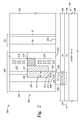
- FIG. 1illustrates a top view of an exemplary hard disk drive (HDD) 100 , according to an embodiment of the invention.
- HDD 100may include one or more magnetic disks 110 , actuator 120 , actuator arms 130 associated with each of the magnetic disks 110 , and spindle motor 140 affixed in a chassis 150 .
- the one or more magnetic disks 110may be arranged vertically as illustrated in FIG. 1 .
- the one or more magnetic disks 110may be coupled with the spindle motor 140 .
- Magnetic disks 110may include circular tracks of data on both the top and bottom surfaces of the disk.
- a magnetic head 180 mounted on a slidermay be positioned on a track. As each disk spins, data may be written on and/or read from the data track.
- Magnetic head 180may be coupled to an actuator arm 130 as illustrated in FIG. 1 .
- Actuator arm 130may be configured to swivel around actuator axis 131 to place magnetic head 180 on a particular data track.
- FIG. 2is a fragmented, cross-sectional side view through the center of a read/write head 200 mounted on a slider 201 and facing magnetic disk 202 .
- the read/write head 200 and magnetic disk 202may correspond to the magnetic head 180 and magnetic disk 110 , respectively in FIG. 1 .
- the magnetic disk 202may be a “dual-layer” medium that includes a perpendicular magnetic data recording layer (RL) 204 on a “soft” or relatively low-coercivity magnetically permeable underlayer (PL) 206 formed on a disk substrate 208 .
- the read/write head 200includes an ABS, a magnetic write head 210 and a magnetic read head 211 , and is mounted such that its ABS is facing the magnetic disk 202 .
- the disk 202moves past the write head 210 in the direction indicated by the arrow 232 , so the portion of slider 201 that supports the read/write head 200 is often called the slider “trailing” end 203 .
- the RL 204is illustrated with perpendicularly recorded or magnetized regions, with adjacent regions having magnetization directions, as represented by the arrows located in the RL 204 . The magnetic fields of the adjacent magnetized regions are detectable by the sensing element 230 as the recorded bits.
- the write head 210includes a magnetic circuit made up of a main pole 212 and a yoke 216 .
- the write head 210also includes a thin film coil 218 shown in the section embedded in non-magnetic material 219 and wrapped around yoke 216 .
- the yoke 216may be omitted, and the coil 218 may wrap around the main pole 212 .
- a write pole 220is magnetically connected to the main pole 212 and has an end 226 that defines part of the ABS of the magnetic write head 210 facing the outer surface of disk 202 .
- Write pole 220is a flared write pole and includes a flare point 222 and a pole tip 224 that includes an end 226 that defines part of the ABS.
- the flaremay extend the entire height of write pole 220 (i.e., from the end 226 of the write pole 220 to the top of the write pole 220 ), or may only extend from the flare point 222 , as shown in FIG. 2 .
- the distance between the flare point 222 and the ABSis between about 30 nm and about 150 nm.
- the write pole 220includes a tapered surface 271 which increases a width of the write pole 220 from a first width W 1 at the ABS to a second width W 2 away from the ABS.
- the width W 1may be between around 60 nm and 200 nm
- the width W 2may be between around 120 nm and 350 nm.
- the tapered region 271is shown with a single straight surface in FIG. 2 , in alternative embodiment, the tapered region 271 may include a plurality of tapered surface with different taper angles with respect to the ABS.
- the taperingimproves magnetic performance. For example, reducing the width W 1 at the ABS may concentrate a magnetic field generated by the write pole 220 over desirable portions of the magnetic disk 202 . In other words, reducing the width W 1 of the write pole 220 at the ABS reduces the probability that tracks adjacent to a desirable track are erroneously altered during writing operations.
- a larger width W 2 of the write pole 220 away from the ABSmay desirably increase the magnetic flux to the write pole 220 , by providing a greater thickness of the write pole 220 in a direction generally parallel to the ABS.
- write currentpasses through coil 218 and induces a magnetic field (shown by dashed line 228 ) from the write pole 220 that passes through the RL 204 (to magnetize the region of the RL 204 beneath the write pole 220 ), through the flux return path provided by the PL 206 , and back to an return pole 250 .
- the greater the magnetic flux of the write pole 220the greater is the probability of accurately writing to desirable regions of the RL 204 .
- FIG. 2further illustrates one embodiment of the return pole or magnetic shield 250 that is separated from write pole 220 by a nonmagnetic gap layer 256 .
- the magnetic shield 250may be a trailing shield wherein substantially all of the shield material is on the trailing end 203 .
- the magnetic shield 250may be a wrap-around shield wherein the shield covers the trailing end 203 and also wraps around the sides of the write pole 220 .
- FIG. 2is a cross section through the center of the read/write head 200 , it represents both trailing and wrap-around embodiments.
- the return polecould be two arms, instead of one, each on either side of the main pole.
- the nonmagnetic gap layer 256has a reduced thickness and forms a shield gap throat 258 .
- the throat gap widthis generally defined as the distance between the write pole 220 and the magnetic shield 250 at the ABS.
- the shield 250is formed of magnetically permeable material (such as Ni, Co and Fe alloys) and gap layer 256 is formed of nonmagnetic material (such as Ta, TaO, Ru, Rh, NiCr, SiC or Al 2 O 3 ).
- a taper 260 in the gap materialprovides a gradual transition from the throat gap width at the ABS to a maximum gap width above the taper 260 . This gradual transition in width forms a tapered bump in the non-magnetic gap layer that allows for greater magnetic flux density from the write pole 220 , while avoiding saturation of the shield 250 .
- the taper 260may extend either more or less than is shown in FIG. 2 .
- the taper 260may extend upwards to an end of shield 250 opposite the ABS (not shown), such that the maximum gap width is at the end of the shield opposite the ABS.
- the gap layer thicknessincreases from a first thickness (the throat gap width) at the ABS to greater thicknesses at a first distance from the ABS, to a greatest thickness at a second distance (greater than the first distance) from the ABS.
- FIG. 3is a schematic cross-sectional view of a write head 300 according to one embodiment.
- the write head 300includes a main pole 212 with the coil 218 wrapped therearound. As discussed above, the main pole 212 should be protected from stray magnetic fields to prevent tunneling of the stray magnetic field through the main pole 212 to the magnetic disk 202 .
- the main pole 212is surrounded by a first non-magnetic material 302 which in turn is surrounded by the return pole 250 .
- the first non-magnetic material 302may comprise alumina.
- the magnetic yoke 216is disposed at an end of the main pole 212 that is opposite the ABS. The magnetic yoke 216 is coupled to both the main pole 212 and the return pole 250 .
- the magnetic yoke 216 , main pole 212 and return pole 250may all comprise the same material.
- the stray magnetic fieldcan enter the write pole parallel to the main pole 212 , as shown by arrow “A” or perpendicular to the main pole 212 , as shown by arrow “B”.
- the stray magnetic fieldcan enter the yoke 216 or the return pole 250 and thus, reach the main pole 212 and negatively impact the write head 300 .
- the magnetic shield 304surrounds the return pole 250 .
- the magnetic shield 304is spaced from the return pole 250 and yoke 216 by a second nonmagnetic layer 306 .
- the second nonmagnetic layer 306may comprise alumina.
- the second nonmagnetic layer 306provides separation to prevent the stray magnetic field from entering the main pole 212 through the yoke 216 .
- the magnetic shield 304can function can be twofold one as an additional return pole by shunting flux from the return pole 250 to assist recording and secondly if the stray field is high or magnetic shield is small some of the stray field load can be shared by the return pole 250 .
- the magnetic shield 304may comprise multiple pieces.
- the magnetic shield 304may comprise the same magnetic material as the return pole 250 , the yoke 216 and/or the main pole 212 .
- FIG. 4is a partial schematic illustration of the back end 402 of a write head.
- the magnetic shield 304is spaced from the yoke 216 and return pole 250 by a distance shown by arrows “d”. If the magnetic shield 304 comprises multiple pieces, namely a back end shield 304 A (i.e. head cap) and a side shield 304 B, then the shields 304 A, 304 B are spaced apart by a gap 404 that may be filled with nonmagnetic material such as alumina.
- the gap 404has a width shown by arrows “ds” such that the width of the gap 404 is less than the distance “d”.
- the stray magnetic fieldwill be less likely to ‘jump’ to the yoke 216 and the return pole 250 . In other words, the stray magnetic field will find the magnetic reluctance greater towards the back end rather than the shield 304 and thus, the stray magnetic field will not travel through the main pole 212 .
- the distance “d” between the shield 304 and the yoke 216 or return pole 250should be chosen such that it does not shift the operating point of the write head.
- FIGS. 5A-5Dare schematic cross-sectional illustrations of the back end 402 of the write head according to various embodiments and in particular, four different head caps 502 ′, 502 ′′, 502 ′′′, 502 ′′′′ or back end shields.
- the shield 304 at the back end 402can have different shapes to guide the stray magnetic field away from the yoke 216 .
- the magnetic yoke 216has a width “g” and the magnetic shield 304 is spaced from the magnetic yoke by a distance “d”.
- the head cap 502 ′, 502 ′′, 502 ′′′, 502 ′′′′ of the magnetic shield 304may have different shapes to direct the stray magnetic fields. As shown in FIG. 5A , the head cap 502 ′ can have a substantially rectangular shape and thus, be spaced from the yoke 216 by the distance “d”. However, as shown in FIGS. 5B-5D , the head cap 502 ′′, 502 ′′′, 502 ′′′′ can have additional spacing 504 between the head cap 502 ′′, 502 ′′′, 502 ′′′′ and the yoke 216 .
- the head cap 502 ′′can have a concave face 506 facing the yoke 216 .
- the concave face 506together with the increased distance represented by spacing 504 and distance “d” collectively, directs the stray magnetic field to pass along the magnetic shield 304 and not penetrate to the magnetic yoke 216 .
- the head cap 502 ′′′can be split into two slabs 502 A, 502 B that are spaced apart by a distance “w” that is less than distance “d”.
- the two slabs 502 A, 502 Bcan be spaced apart by nonmagnetic material such as alumina.
- the head cap 502 ′′′′can have multiple slabs 508 that are each spaced apart by a distance “a” that is small enough for the magnetic flux to spread, but not large enough so that the magnetic flux would filter to the yoke 216 .
- the slabs 508provide a more gradual path for the magnetic flux to be diverted and reduce the density of the stray magnetic field at every slab 508 .
- the slabs to implement the shieldsuch as in 5 C and 5 D, the magnetic volume of the shield is reduced so coupling of that shield to the main write head is further reduced but much of the stray fielding capability is retained.
- FIGS. 6A and 6Bshow ABS views of the magnetic shield 304 and return pole 250 .
- the shield 304may extend longitudinally beyond the return pole 250 by a distance “f” in each direction.
- the side surface 602 of the magnetic shield 304may have a sloped surface to increase the surface area and thus, increase the shunting ability of the magnetic shield 304 .
- FIG. 7is a schematic cross-sectional illustration of a write head 700 according to another embodiment illustrating the side shield 702 according to one embodiment.
- a single, solid piece side shield 304 Bis shown in FIG. 4 .
- the side shield 702comprises several pieces with each piece having a flare portion 704 .
- the flare portions 704direct the stray magnetic field out through the flare portion 704 and thus, away from the write head 700 .
- FIG. 8is a schematic cross-sectional illustration of a write head 800 according to another embodiment illustrating the side shield 802 B according to another embodiment.
- the return pole 250 at the ABSis longer in the cross-track direction.
- the shield 304is recessed from the ABS.
- the side shield 802 Boverlaps with the head cap 802 A (or back end shield). The overlapping, together with recess from the ABS, compensate for the larger wrap around shield at the ABS.
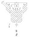
- FIG. 9is a cross-sectional illustration of the write head 900 where the side shield 304 B comprises a plurality of slabs 902 .
- the side shield 304 Bextends close to the ABS.
- the slabs 902provide a more gradual path for the magnetic flux to be diverted and reduce the density of the stray magnetic field at every slab 902 . Additionally, by extending to the ABS, the magnetic load on the wrap around shield is reduced so that the efficiency of the shielding at the ABS is improved.
- the magnetic shieldprotects the main pole of the PMR write head.
- the magnetic shield at the backgap/Yokeprovides a low reluctance path for the stray magnetic field so that the stray field travels through the shield and is not funneled into the main pole.
- the shieldprovides an alternate path for the stray magnetic field density to decrease prior to teaching the disk. If the stray magnetic field is large, then some of the stray magnetic field may diffuse to the return pole.
- the magnetic shieldis designed to protect the write head from stray magnetic fields in both parallel and perpendicular directions to the ABS.
- the magnetic shield at the magnetic backgapallows the write head for the PMR to improve the magnetic backgap coupling for the return flux to the main pole.
- shieldsare formed of magnetically permeable material (such as Ni, Co and Fe alloys) and nonmagnetic layer that is between the shields and the yoke/return pole is formed of nonmagnetic material (such as Ta, TaO, Ru, Rh, NiCr, SiC or Al 2 O 3 ).
- the main polecan be isolated from stray magnetic fields and thus, operate properly.
Landscapes
- Engineering & Computer Science (AREA)
- Manufacturing & Machinery (AREA)
- Physics & Mathematics (AREA)
- Electromagnetism (AREA)
- Magnetic Heads (AREA)
Abstract
Description
Claims (22)
Priority Applications (1)
| Application Number | Priority Date | Filing Date | Title |
|---|---|---|---|
| US14/136,830US9269378B2 (en) | 2013-12-20 | 2013-12-20 | Stray field shielding for perpendicular magnetic recording write head |
Applications Claiming Priority (1)
| Application Number | Priority Date | Filing Date | Title |
|---|---|---|---|
| US14/136,830US9269378B2 (en) | 2013-12-20 | 2013-12-20 | Stray field shielding for perpendicular magnetic recording write head |
Publications (2)
| Publication Number | Publication Date |
|---|---|
| US20150179192A1 US20150179192A1 (en) | 2015-06-25 |
| US9269378B2true US9269378B2 (en) | 2016-02-23 |
Family
ID=53400702
Family Applications (1)
| Application Number | Title | Priority Date | Filing Date |
|---|---|---|---|
| US14/136,830Expired - Fee RelatedUS9269378B2 (en) | 2013-12-20 | 2013-12-20 | Stray field shielding for perpendicular magnetic recording write head |
Country Status (1)
| Country | Link |
|---|---|
| US (1) | US9269378B2 (en) |
Families Citing this family (1)
| Publication number | Priority date | Publication date | Assignee | Title |
|---|---|---|---|---|
| US20090159682A1 (en)* | 2007-12-24 | 2009-06-25 | Dynamics Inc. | Cards and devices with multi-function magnetic emulators and methods for using same |
Citations (32)
| Publication number | Priority date | Publication date | Assignee | Title |
|---|---|---|---|---|
| US5311387A (en)* | 1987-07-29 | 1994-05-10 | Digital Equipment Corporation | Three-pole magnetic recording head with high readback resolution |
| US6728065B2 (en) | 2001-03-29 | 2004-04-27 | Seagate Technology Llc | Single pole magnetic recording head for perpendicular magnetic recording |
| US6798615B1 (en) | 2000-03-24 | 2004-09-28 | Seagate Technology Llc | Perpendicular recording head with return poles which reduce flux antenna effect |
| US6922317B2 (en)* | 2003-01-10 | 2005-07-26 | International Business Machines Corporation | Magnetic flux closure layer for laminated magnetic shields of magnetic heads |
| US7002775B2 (en)* | 2003-09-30 | 2006-02-21 | Hitachi Global Storage Technologies Netherlands B.V. | Head for perpendicular magnetic recording with a shield structure connected to the return pole piece |
| US20060092569A1 (en) | 2004-10-29 | 2006-05-04 | Hitachi Global Storage Technologies | Winged pole and shield structure for reducing stray field in a perpendicular write head |
| US7057837B2 (en) | 2002-10-17 | 2006-06-06 | Hitachi Global Storage Technologies Netherlands B.V. | Flux closed single pole perpendicular head for ultra narrow track |
| US20060245108A1 (en) | 2005-04-27 | 2006-11-02 | Hitachi Global Storage Technologies | Flux shunt structure for reducing return pole corner fields in a perpendicular magnetic recording head |
| US20070035885A1 (en)* | 2005-08-12 | 2007-02-15 | Samsung Electronics Co., Ltd. | Perpendicular magnetic recording head and method of manufacturing the same |
| US7394620B2 (en)* | 2003-04-28 | 2008-07-01 | Kabushiki Kaisha Toshiba | Perpendicular magnetic recording head and magnetic disc apparatus |
| US7529066B2 (en)* | 2005-12-14 | 2009-05-05 | Hitachi Global Storage Technologies Netherlands B.V. | Magnetoresistive sensor having magnetic layers with tailored magnetic anisotropy induced by direct ion milling |
| US7561379B2 (en)* | 2005-10-28 | 2009-07-14 | Seagate Technology Llc | Laminated return pole for suppressing side track erasure |
| US7649711B2 (en) | 2004-10-29 | 2010-01-19 | Hitachi Global Storage Technologies Netherlands B.V. | Double notched shield and pole structure for stray field reduction in a magnetic head |
| US20100061016A1 (en)* | 2008-09-05 | 2010-03-11 | Headway Technologies, Inc. | Method to make an integrated side shield PMR head with non conformal side gap |
| US7983002B2 (en)* | 2007-06-26 | 2011-07-19 | Seagate Technology Llc | Wire-assisted magnetic write device with a gapped trailing shield |
| US8054586B2 (en) | 2005-11-23 | 2011-11-08 | Hitachi Global Storage Technologies Netherlands B.V. | Write head design and method for reducing adjacent track interference at very narrow track widths |
| US8120874B2 (en)* | 2007-12-28 | 2012-02-21 | Hitachi Global Storage Technologies Netherlands B.V. | Perpendicular write head having a modified wrap-around shield to improve overwrite, adjacent track interference and magnetic core width dependence on skew angle |
| US8149538B2 (en)* | 2009-09-29 | 2012-04-03 | Kabushiki Kaisha Toshiba | Magnetic head for perpendicular recording and disk drive with the same |
| US8169741B2 (en)* | 2006-05-11 | 2012-05-01 | Kabushiki Kaisha Toshiba | Perpendicular magnetic recording head with side shield and magnetic disk apparatus |
| US8233237B2 (en)* | 2010-06-21 | 2012-07-31 | Tdk Corporation | Perpendicular magnetic write head and magnetic recording device |
| US20120281314A1 (en) | 2011-05-04 | 2012-11-08 | Seagate Technology Llc | Magnetic Shield with Flux Concentration Feature |
| US8315013B2 (en) | 2010-05-10 | 2012-11-20 | International Business Machines Corporation | Magnetic write head with flux diverting structure |
| US8339734B2 (en) | 2010-04-23 | 2012-12-25 | Hitachi Global Storage Technologies Netherlands B.V. | Magnetic write head having a wrap around trailing shield with an asymetrical side gap |
| US8345385B2 (en)* | 2010-10-29 | 2013-01-01 | Seagate Technology Llc | Shield with continuously concave inner sidewall |
| US8345388B2 (en) | 2005-04-28 | 2013-01-01 | Headway Technologies, Inc. | Perpendicular recording device having reduced sensitivity to external fields |
| US20130120876A1 (en) | 2011-11-11 | 2013-05-16 | Hitachi Global Storage Technologies Netherlands B.V. | Magnetic write head with novel shield structure |
| US8649125B1 (en)* | 2012-09-14 | 2014-02-11 | Seagate Technology Llc | Pole tip shield for a magnetic write element having notched or truncated side shields |
| US8737022B2 (en)* | 2012-07-13 | 2014-05-27 | Tdk Corporation | Multilayer film, magnetic head, magnetic head device, magnetic recording/reproducing apparatus and method for manufacturing multilayer film |
| US8792208B1 (en)* | 2012-05-25 | 2014-07-29 | Western Digital (Fremont), Llc | Method for providing side shields having non-conformal regions for a magnetic recording transducer |
| US8830625B2 (en)* | 2012-11-29 | 2014-09-09 | Seagate Technology Llc | Data writer with tapered side shield sidewalls |
| US8848316B2 (en)* | 2010-09-28 | 2014-09-30 | Seagate Technology Llc | Perpendicular write head with laminated side shields |
| US8929027B1 (en)* | 2014-04-28 | 2015-01-06 | HGST Netherlands B.V. | Magnetic write head with tapered side gap for reduced far track interference |
- 2013
- 2013-12-20USUS14/136,830patent/US9269378B2/ennot_activeExpired - Fee Related
Patent Citations (33)
| Publication number | Priority date | Publication date | Assignee | Title |
|---|---|---|---|---|
| US5311387A (en)* | 1987-07-29 | 1994-05-10 | Digital Equipment Corporation | Three-pole magnetic recording head with high readback resolution |
| US6798615B1 (en) | 2000-03-24 | 2004-09-28 | Seagate Technology Llc | Perpendicular recording head with return poles which reduce flux antenna effect |
| US6728065B2 (en) | 2001-03-29 | 2004-04-27 | Seagate Technology Llc | Single pole magnetic recording head for perpendicular magnetic recording |
| US7057837B2 (en) | 2002-10-17 | 2006-06-06 | Hitachi Global Storage Technologies Netherlands B.V. | Flux closed single pole perpendicular head for ultra narrow track |
| US6922317B2 (en)* | 2003-01-10 | 2005-07-26 | International Business Machines Corporation | Magnetic flux closure layer for laminated magnetic shields of magnetic heads |
| US7394620B2 (en)* | 2003-04-28 | 2008-07-01 | Kabushiki Kaisha Toshiba | Perpendicular magnetic recording head and magnetic disc apparatus |
| US7002775B2 (en)* | 2003-09-30 | 2006-02-21 | Hitachi Global Storage Technologies Netherlands B.V. | Head for perpendicular magnetic recording with a shield structure connected to the return pole piece |
| US7649711B2 (en) | 2004-10-29 | 2010-01-19 | Hitachi Global Storage Technologies Netherlands B.V. | Double notched shield and pole structure for stray field reduction in a magnetic head |
| US20060092569A1 (en) | 2004-10-29 | 2006-05-04 | Hitachi Global Storage Technologies | Winged pole and shield structure for reducing stray field in a perpendicular write head |
| US20060245108A1 (en) | 2005-04-27 | 2006-11-02 | Hitachi Global Storage Technologies | Flux shunt structure for reducing return pole corner fields in a perpendicular magnetic recording head |
| US8345388B2 (en) | 2005-04-28 | 2013-01-01 | Headway Technologies, Inc. | Perpendicular recording device having reduced sensitivity to external fields |
| US20070035885A1 (en)* | 2005-08-12 | 2007-02-15 | Samsung Electronics Co., Ltd. | Perpendicular magnetic recording head and method of manufacturing the same |
| US7561379B2 (en)* | 2005-10-28 | 2009-07-14 | Seagate Technology Llc | Laminated return pole for suppressing side track erasure |
| US8054586B2 (en) | 2005-11-23 | 2011-11-08 | Hitachi Global Storage Technologies Netherlands B.V. | Write head design and method for reducing adjacent track interference at very narrow track widths |
| US7529066B2 (en)* | 2005-12-14 | 2009-05-05 | Hitachi Global Storage Technologies Netherlands B.V. | Magnetoresistive sensor having magnetic layers with tailored magnetic anisotropy induced by direct ion milling |
| US8169741B2 (en)* | 2006-05-11 | 2012-05-01 | Kabushiki Kaisha Toshiba | Perpendicular magnetic recording head with side shield and magnetic disk apparatus |
| US7983002B2 (en)* | 2007-06-26 | 2011-07-19 | Seagate Technology Llc | Wire-assisted magnetic write device with a gapped trailing shield |
| US8120874B2 (en)* | 2007-12-28 | 2012-02-21 | Hitachi Global Storage Technologies Netherlands B.V. | Perpendicular write head having a modified wrap-around shield to improve overwrite, adjacent track interference and magnetic core width dependence on skew angle |
| US20100061016A1 (en)* | 2008-09-05 | 2010-03-11 | Headway Technologies, Inc. | Method to make an integrated side shield PMR head with non conformal side gap |
| US8149538B2 (en)* | 2009-09-29 | 2012-04-03 | Kabushiki Kaisha Toshiba | Magnetic head for perpendicular recording and disk drive with the same |
| US8339734B2 (en) | 2010-04-23 | 2012-12-25 | Hitachi Global Storage Technologies Netherlands B.V. | Magnetic write head having a wrap around trailing shield with an asymetrical side gap |
| US8315013B2 (en) | 2010-05-10 | 2012-11-20 | International Business Machines Corporation | Magnetic write head with flux diverting structure |
| US8233237B2 (en)* | 2010-06-21 | 2012-07-31 | Tdk Corporation | Perpendicular magnetic write head and magnetic recording device |
| US8848316B2 (en)* | 2010-09-28 | 2014-09-30 | Seagate Technology Llc | Perpendicular write head with laminated side shields |
| US8345385B2 (en)* | 2010-10-29 | 2013-01-01 | Seagate Technology Llc | Shield with continuously concave inner sidewall |
| US8675307B2 (en)* | 2010-10-29 | 2014-03-18 | Seagate Technology Llc | Shield with continuously and throat regions adjacent a main pole |
| US20120281314A1 (en) | 2011-05-04 | 2012-11-08 | Seagate Technology Llc | Magnetic Shield with Flux Concentration Feature |
| US20130120876A1 (en) | 2011-11-11 | 2013-05-16 | Hitachi Global Storage Technologies Netherlands B.V. | Magnetic write head with novel shield structure |
| US8792208B1 (en)* | 2012-05-25 | 2014-07-29 | Western Digital (Fremont), Llc | Method for providing side shields having non-conformal regions for a magnetic recording transducer |
| US8737022B2 (en)* | 2012-07-13 | 2014-05-27 | Tdk Corporation | Multilayer film, magnetic head, magnetic head device, magnetic recording/reproducing apparatus and method for manufacturing multilayer film |
| US8649125B1 (en)* | 2012-09-14 | 2014-02-11 | Seagate Technology Llc | Pole tip shield for a magnetic write element having notched or truncated side shields |
| US8830625B2 (en)* | 2012-11-29 | 2014-09-09 | Seagate Technology Llc | Data writer with tapered side shield sidewalls |
| US8929027B1 (en)* | 2014-04-28 | 2015-01-06 | HGST Netherlands B.V. | Magnetic write head with tapered side gap for reduced far track interference |
Non-Patent Citations (1)
| Title |
|---|
| Kiyoshi Yamakawa et al.; "High Writability Head with Robustness Against Stray Field and Narrow-Track Recording Properties"; IEEE Transactions on Magnetics, vol. 38, No. 4. Jul. 2002, 6 pages. |
Also Published As
| Publication number | Publication date |
|---|---|
| US20150179192A1 (en) | 2015-06-25 |
Similar Documents
| Publication | Publication Date | Title |
|---|---|---|
| US7990653B2 (en) | Perpendicular recording magnetic head with a main magnetic pole piece and an auxiliary magnetic pole piece | |
| US9230576B1 (en) | Scissor reader with side shield decoupled from bias material | |
| TWI417876B (en) | Magnetic write head, magnetic head, and magnetic data recording system | |
| CN101046973B (en) | Two step corner recess for secondary stray field reduction in a perpendicular magnetic recording head | |
| KR20050031937A (en) | Head for perpendicular magnetic recording with a shield structure connected to the return pole piece | |
| JP2015130229A (en) | Device including write pole tip | |
| US8724258B2 (en) | Slanted bump design for magnetic shields in perpendicular write heads and method of making same | |
| US20090262464A1 (en) | Perpendicular magnetic write head having a wrap around shield constructed of a low permeability material for reduced adjacent track erasure | |
| US20140377589A1 (en) | Narrow read-gap head with recessed afm | |
| US7538976B2 (en) | Trailing shield design for reducing wide area track erasure (water) in a perpendicular recording system | |
| US8553360B2 (en) | Magnetic recording head having write pole with higher magnetic moment towards trailing edge | |
| JP5863304B2 (en) | Perpendicular magnetic write head with wrapping trailing magnetic shield magnetically biased in the cross-track direction | |
| US20120188666A1 (en) | Magnetic head for perpendicular magnetic recording having a main pole and a shield | |
| US20150380017A1 (en) | Partial main pole lamination for pole erasure improvement | |
| US9449635B2 (en) | Method for forming a magnetic head for perpendicular magnetic recording | |
| US9406322B2 (en) | Graded side shield gap reader | |
| US20080112088A1 (en) | Perpendicular magnetic write head having a wrap around trailing shield with a flux return path | |
| CN100416655C (en) | Slotted shield and pole structure with slanted wings for perpendicular recording | |
| US20120127611A1 (en) | Modified shield design to eliminate the far-field WATE problem | |
| US7768741B2 (en) | Magnetic write head design for reducing wide area track erasure | |
| US9269378B2 (en) | Stray field shielding for perpendicular magnetic recording write head | |
| US8902549B1 (en) | Enhanced pinning property by inserted Si seed layer | |
| US9082434B2 (en) | Asymmetric sensitivity reader | |
| US8976484B1 (en) | Magnetic recording with tilted media in the cross track direction | |
| US8449752B2 (en) | Trailing plated step |
Legal Events
| Date | Code | Title | Description |
|---|---|---|---|
| AS | Assignment | Owner name:HGST NETHERLANDS B.V., NETHERLANDS Free format text:ASSIGNMENT OF ASSIGNORS INTEREST;ASSIGNOR:NARAYANA, SUPRADEEP;REEL/FRAME:031867/0336 Effective date:20131218 | |
| ZAAA | Notice of allowance and fees due | Free format text:ORIGINAL CODE: NOA | |
| ZAAB | Notice of allowance mailed | Free format text:ORIGINAL CODE: MN/=. | |
| STCF | Information on status: patent grant | Free format text:PATENTED CASE | |
| AS | Assignment | Owner name:WESTERN DIGITAL TECHNOLOGIES, INC., CALIFORNIA Free format text:ASSIGNMENT OF ASSIGNORS INTEREST;ASSIGNOR:HGST NETHERLANDS B.V.;REEL/FRAME:040829/0516 Effective date:20160831 | |
| MAFP | Maintenance fee payment | Free format text:PAYMENT OF MAINTENANCE FEE, 4TH YEAR, LARGE ENTITY (ORIGINAL EVENT CODE: M1551); ENTITY STATUS OF PATENT OWNER: LARGE ENTITY Year of fee payment:4 | |
| AS | Assignment | Owner name:JPMORGAN CHASE BANK, N.A., AS AGENT, ILLINOIS Free format text:SECURITY INTEREST;ASSIGNOR:WESTERN DIGITAL TECHNOLOGIES, INC.;REEL/FRAME:052915/0566 Effective date:20200113 | |
| AS | Assignment | Owner name:WESTERN DIGITAL TECHNOLOGIES, INC., CALIFORNIA Free format text:RELEASE OF SECURITY INTEREST AT REEL 052915 FRAME 0566;ASSIGNOR:JPMORGAN CHASE BANK, N.A.;REEL/FRAME:059127/0001 Effective date:20220203 | |
| AS | Assignment | Owner name:JPMORGAN CHASE BANK, N.A., ILLINOIS Free format text:PATENT COLLATERAL AGREEMENT - A&R LOAN AGREEMENT;ASSIGNOR:WESTERN DIGITAL TECHNOLOGIES, INC.;REEL/FRAME:064715/0001 Effective date:20230818 Owner name:JPMORGAN CHASE BANK, N.A., ILLINOIS Free format text:PATENT COLLATERAL AGREEMENT - DDTL LOAN AGREEMENT;ASSIGNOR:WESTERN DIGITAL TECHNOLOGIES, INC.;REEL/FRAME:067045/0156 Effective date:20230818 | |
| FEPP | Fee payment procedure | Free format text:MAINTENANCE FEE REMINDER MAILED (ORIGINAL EVENT CODE: REM.); ENTITY STATUS OF PATENT OWNER: LARGE ENTITY | |
| LAPS | Lapse for failure to pay maintenance fees | Free format text:PATENT EXPIRED FOR FAILURE TO PAY MAINTENANCE FEES (ORIGINAL EVENT CODE: EXP.); ENTITY STATUS OF PATENT OWNER: LARGE ENTITY | |
| STCH | Information on status: patent discontinuation | Free format text:PATENT EXPIRED DUE TO NONPAYMENT OF MAINTENANCE FEES UNDER 37 CFR 1.362 | |
| FP | Lapsed due to failure to pay maintenance fee | Effective date:20240223 |