US9269093B2 - Methods and apparatus to monitor shoppers in a monitored environment - Google Patents
Methods and apparatus to monitor shoppers in a monitored environmentDownload PDFInfo
- Publication number
- US9269093B2 US9269093B2US13/475,571US201213475571AUS9269093B2US 9269093 B2US9269093 B2US 9269093B2US 201213475571 AUS201213475571 AUS 201213475571AUS 9269093 B2US9269093 B2US 9269093B2
- Authority
- US
- United States
- Prior art keywords
- data
- path
- location
- travel
- sensor
- Prior art date
- Legal status (The legal status is an assumption and is not a legal conclusion. Google has not performed a legal analysis and makes no representation as to the accuracy of the status listed.)
- Active, expires
Links
Images


Classifications
- G—PHYSICS
- G06—COMPUTING OR CALCULATING; COUNTING
- G06Q—INFORMATION AND COMMUNICATION TECHNOLOGY [ICT] SPECIALLY ADAPTED FOR ADMINISTRATIVE, COMMERCIAL, FINANCIAL, MANAGERIAL OR SUPERVISORY PURPOSES; SYSTEMS OR METHODS SPECIALLY ADAPTED FOR ADMINISTRATIVE, COMMERCIAL, FINANCIAL, MANAGERIAL OR SUPERVISORY PURPOSES, NOT OTHERWISE PROVIDED FOR
- G06Q30/00—Commerce
- G06Q30/02—Marketing; Price estimation or determination; Fundraising
- G—PHYSICS
- G06—COMPUTING OR CALCULATING; COUNTING
- G06Q—INFORMATION AND COMMUNICATION TECHNOLOGY [ICT] SPECIALLY ADAPTED FOR ADMINISTRATIVE, COMMERCIAL, FINANCIAL, MANAGERIAL OR SUPERVISORY PURPOSES; SYSTEMS OR METHODS SPECIALLY ADAPTED FOR ADMINISTRATIVE, COMMERCIAL, FINANCIAL, MANAGERIAL OR SUPERVISORY PURPOSES, NOT OTHERWISE PROVIDED FOR
- G06Q10/00—Administration; Management
- G06Q10/06—Resources, workflows, human or project management; Enterprise or organisation planning; Enterprise or organisation modelling
- G06Q10/063—Operations research, analysis or management
- G06Q10/0631—Resource planning, allocation, distributing or scheduling for enterprises or organisations
- G06Q10/06316—Sequencing of tasks or work
- H—ELECTRICITY
- H04—ELECTRIC COMMUNICATION TECHNIQUE
- H04H—BROADCAST COMMUNICATION
- H04H60/00—Arrangements for broadcast applications with a direct linking to broadcast information or broadcast space-time; Broadcast-related systems
- H04H60/35—Arrangements for identifying or recognising characteristics with a direct linkage to broadcast information or to broadcast space-time, e.g. for identifying broadcast stations or for identifying users
- H04H60/49—Arrangements for identifying or recognising characteristics with a direct linkage to broadcast information or to broadcast space-time, e.g. for identifying broadcast stations or for identifying users for identifying locations
- H04H60/52—Arrangements for identifying or recognising characteristics with a direct linkage to broadcast information or to broadcast space-time, e.g. for identifying broadcast stations or for identifying users for identifying locations of users
Definitions
- the present disclosurerelates generally to consumer monitoring and, more particularly, to methods and apparatus to monitor shoppers in a retail environment.
- Retail establishments and product manufacturersare often interested in the shopping activities, behaviors, and/or habits of people in a retail environment.
- Consumer activity related to shoppingcan be used to correlate product sales with particular shopping behaviors and/or to improve placements of products, advertisements, and/or other product-related information in a retail environment.
- Known techniques for monitoring consumer activities in retail establishmentsinclude conducting surveys, counting patrons, and/or conducting visual inspections of shoppers or patrons in the retail establishments.
- Acquiring information related to shopping activities, behaviors, and/or habits of people in a retail environmentenables retail establishments to arrange their store and product layouts in a manner that is most conducive to maximizing sales of such products by positively influencing shoppers. Acquiring such information also enables product manufacturers to design product packaging that influences shoppers exhibiting certain behaviors or shopping patterns and/or to design different product packaging to target different shopper behaviors, patterns, or habits associated with different geographic areas. Advertisers can also benefit from metering shopping activities, behaviors, and/or habits of people in a retail environment by using such information to create more effective advertisements and/or position advertisements in more opportune locations within different retail establishments. In addition, advertisers can assess which advertisements are more effective than others.
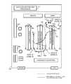
- FIG. 1illustrates a plan view of an example retail establishment having actual and measured shopper paths of travel overlaid thereon.
- FIG. 2depicts an actual shopper path of travel shown in association with a measured shopper path of travel and an adjusted shopper path of travel.
- FIG. 3depicts a system that can be installed in a retail establishment to generate path of travel information and analyze shopper activity in the retail establishment.
- FIG. 4depicts a data structure that can be used to store path of travel information associated with a shopper in a retail establishment.
- FIG. 5depicts a data structure that can be used to associate zones in a retail establishment with respective location boundaries in the retail establishment.
- FIG. 6is an example location monitoring system that may be used to implement a location detection system to track shoppers' paths of travel in a retail establishment.
- FIG. 7is a block diagram of an example tag that can be worn or carried by a shopper to generate path of travel information as the shopper moves through a retail establishment.
- FIG. 8is a block diagram of a data collector and processor that can be used to collect, process, and analyze measured path of travel information and person detection event information associated with shoppers in a retail establishment.
- FIG. 9is a block diagram of an example apparatus that can be used to analyze measured shopper path of travel information to generate adjusted path of travel information.
- FIG. 10is a flow diagram representative of machine readable instructions that can be executed by the tag of FIGS. 1 and 7 to emit chirps for generating measured path of travel information as the shopper moves through the retail establishment of FIG. 1 .
- FIG. 11is a flow diagram representative of machine readable instructions that can be executed by the data collector and processor of FIGS. 1 and 8 to collect measured path of travel information.
- FIG. 12is a flow diagram representative of machine readable instructions that can be executed to cause the tag of FIGS. 1 and 7 to emit chirps for generating measured path of travel information as the shopper moves through the retail establishment of FIG. 1 .
- FIG. 14depicts another flow diagram representative of machine readable instructions that can be executed by the shopper path of travel inference apparatus 312 of FIGS. 3 and 9 to process the measured path of travel information to generate adjusted path of travel information.
- FIG. 15is a block diagram of an example processor system that may be used to execute the example machine readable instructions of FIGS. 10-14 .
- the example methods and apparatus described hereinmay be implemented by a consumer metering entity, by a retail business, or by any other entity interested in collecting and/or analyzing information to monitor persons in a monitored environment.
- the example methods and apparatusmay be used to monitor shopper traffic.
- the example methods and apparatuscan be used to determine shopper locations associated with shopper traffic and the times at which locations of those shoppers are detected. In addition, paths of travel of different shoppers can be determined.
- the example methods and apparatusmay be used to help marketing and media professionals better understand the amount of shopper traffic and shopper traffic trends in retail establishments. Such information may be used to determine how to reach and influence shoppers that buy goods in retail establishments. For example, by monitoring in-store shopper quantities and traffic, the example methods and apparatus described herein can be used to determine when shopper traffic is heaviest and lightest and to determine locations most frequented in a retail establishment.
- an example implementationinvolves using people detection devices located throughout a retail establishment in connection with a location tracking system in the retail establishment.
- the people detection devicescollect shopper detection event data (or person detection event data) in different aisles or zones of the retail establishment indicative of when shoppers move proximate to the people detection devices, while tracking beacons (access points, chirp receivers, signal receivers, etc.) associated with the location tracking system are located throughout the store to collect measured path of travel information associated with respective shoppers.
- the shopper detection event data collected using the people detection devicesis used in connection with the measured path of travel information to increase the accuracy of the path of travel information by adjusting or correcting erroneous or inaccurate location data in the measured path of travel information.
- the path of travel informationcan then be used to identify products, advertisements, and/or other media or information to which shoppers were exposed along those path(s).
- location tracking systemsare relatively more expensive than people detection devices.
- the location tracking systemcan be installed using less tracking beacons located throughout a store than would otherwise be needed.
- the location tracking systemwould then generate less granular path of travel information than could otherwise be achieved with more tracking beacons, the cost of the location tracking system can be substantially reduced.
- the shopper detection event data from the people detection devicesis used to confirm the aisle or zone of a retail establishment in which a shopper was located whenever a suspect location datum generated by the location tracking system is detected.
- FIG. 1a plan view of an example retail establishment 100 is shown having an actual shopper path of travel 102 and a measured shopper path of travel 104 overlaid thereon.
- the retail establishment 100is a grocery store.
- the example methods and apparatus described hereincan be used to monitor shoppers' paths of travel in other monitored environments such as other types of retail establishments (e.g., department stores, clothing stores, specialty stores, hardware stores, etc.) or commercial establishments (e.g., entertainment venues, amusement parks, sports arenas/stadiums, etc.).
- the retail establishment 100is shown as having aisles A-C representative of different zones of the retail establishment.
- a zoneis an area of a monitored environment accessible by people who are to be monitored to generate traffic counts and paths of travel of those people.
- the boundaries of a zonemay relate to product layout throughout the retail establishment, furniture layout, and/or other boundary-creating features (e.g., an outdoor garden and lawn area).
- zonesare created based on the types of products that are sold in particular areas of a retail establishment.
- the actual shopper path of travel 102indicates the actual path traveled by a shopper through aisles 1 and 2 of the retail establishment 100
- the measured shopper path of travel 104indicates the path of travel data collected by a location tracking system having location detection devices 106 a - c located throughout the retail establishment 100 .
- the location detection devices 106 a - care implemented using wireless radio frequency (RF) communication units.
- RFradio frequency
- the data collected by the location tracking systemindicates that the shopper exited aisle A and entered into aisle B. However, while in aisle B the shopper was measured as having detoured momentarily back into aisle A and also subsequently detoured momentarily into aisle C.
- the example methods and apparatus described hereincan be used to detect and correct or adjust the erroneous excursions or deviations based on shopper detection event data generated using people detectors 108 a - h located throughout the retail establishment 100 .
- shopper detection event data generated using the people detectors 108 a - hfacilitates generating relatively more accurate path of travel information to more accurately represent the actual shopper path of travel 102 .
- an adjusted (or processed) path of travel 202 generated based on the measured path of travel 104 and shopper detection event datais shown relative to the actual path of travel 102 and the measured path of travel 104 .
- the actual shopper path of travel 102is relatively more similar to the adjusted shopper path of travel 202 than to the measured shopper path of travel 104 .
- a mobile tag 110is provided for mounting on shopping carts such as the shopping cart 112 .
- tags that are substantially similar or identical to the tag 110can be mounted to shopping baskets or can be issued to shoppers when they enter the retail establishment 100 and worn or carried by those shoppers as they move through the retail establishment 100 .
- the retail establishment 100is provided with a data collector and processor 114 that is used to collect and process measured path of travel information.
- the data collector and processor 114can be communicatively coupled to a server at a data collection facility (not shown) via a telephone line, a broadband internet connection, a wireless cellular connection, and/or any other suitable communication interface.
- the data collector and processor 114can communicate measured path of travel information, shopper detection event data, and/or adjusted path of travel information to the data collection facility for subsequent analyses.
- the data collector and processor 114can collect and analyze the measured shopper path of travel 104 to generate the adjusted shopper path of travel 202
- the data collector and processor 114can communicate the measured shopper path of travel 104 along with shopper detection event data to the data collection facility, and the data collection facility can analyze the measured shopper path of travel 104 to generate the adjusted shopper path of travel 202 .
- Each mobile tag(e.g., the tag 110 ) is encoded with a unique tag identifier and periodically emits a chirp or any other type of signal carrying information or data representative of its unique tag identifier as it is moved through the retail establishment 100 .
- the location detection devices 106 a - cdetect the chirps or signals from the mobile tags and communicate signal properties of the chirps and/or data embedded in the chirps to the data collector and processor 114 .
- the data collector and processor 114can use the signal properties and/or the chirp-embedded data to determine the different locations of the tag 110 and store the location information in association with the unique tag identifier of the tag 110 to represent the measured path of travel 104 .
- location data forming the measured shopper path of travel 104 and collected at times t 0 -t 8is analyzed to determine whether any path segments of the measured path of travel 104 have suspect excursions, deviations, or movements between different zones.
- the location data having the error or inaccuracyis changed, adjusted or otherwise corrected to provide a more accurate representation of the actual shopper path of travel 102 .
- An example manner of detecting such suspect excursions, deviations, or movementsinvolves identifying the times at which a shopper traversed a predetermined entrance and a predetermined exit of a zone (e.g., an aisle) and determining whether any location points temporally collected between the entrance and exit events indicate a location other than the zone that was entered or exited through the predetermined entrance and predetermined exit.
- a zonee.g., an aisle
- a match or substantial matchis found between a timestamp of a shopper detection event and a timestamp of a collected location point along the measured path of travel 104 .
- a substantial match within a threshold time or time difference between a timestamp of a shopper detection event generated using the people detector 108 e and a timestamp of a location point collected using one or more of the location detection devices 106 a - c at time t 4indicates that the shopper was in aisle B.
- the threshold time range or time difference defining when a substantial match between timestamps is confirmedcan be selected based on experimental trials used to determine a maximum or typical temporal misalignment between the time the tag 110 emits a chirp for location detection purposes and the time that a people detector 108 a - h detects the person associated with the tag 110 .
- a feedback techniquecan be implemented to increase the chirp rate (or signal emission rate) of the tag 110 when it approaches the locations of the people detectors 108 a - h .
- a feedback techniquemay involve providing the tag 110 with an infrared sensor and implementing the people detectors 108 a - h using infrared transmitters and receivers.
- the people detectors 108 a - hare configured to generate a shopper detection event when a shopper breaks the infrared beam transmitted by the infrared transmitter toward the infrared receiver.
- the tag 110can be configured to increase its chirp rate (or signal emission rate) to emit chirps (or signals) more frequently when it detects infrared light from one (or more) of the people detectors 108 a - h .
- relatively more location data and corresponding timestampscan be generated for the tag 110 when the tag 110 is in the vicinity of the people detectors 108 a - h .
- Having relatively more location data and corresponding timestamps when the tag 110 is near the people detectors 108 a - hincreases the probability of finding a match between a timestamp of a shopper detection event and a timestamp of a collected location datum to confirm that a shopper was in a particular zone (e.g., one of the aisles A-C) of the retail establishment 100 .
- a feedback technique to increase the tag chirp ratemay be implemented by providing the tag 110 with data reception capabilities in which the tag 110 can be instructed by, for example, the data collector and processor 114 , to increase its chirp rate when the data collector and processor 114 determines that the tag 110 is near or proximate to any of the people detectors 108 a - h .
- the data collector and processor 114can transmit chirp triggers at a relatively higher rate than the rate at which the tag 110 normally emits chirps. In this manner, the chirp triggers can cause the tag 110 to emit chirps at higher rates.
- the data collector and processor 114can determine, in real-time or substantially real-time, a location of the tag 110 .
- the example system 300is provided with a path of travel information store 308 that is used to store the measured path of travel information 304 and a separate shopper event information store 310 , which used to store the shopper detection event information 306 a - h .
- the example system 300is also provided with a shopper path of travel inference apparatus 312 to analyze the measured path of travel information 304 in connection with the shopper event information 306 a - h to improve the accuracy of the measured path of travel information 304 by generating, for example, the adjusted shopper path of travel 202 shown in FIG. 2 .
- the relatively more accurate adjusted shopper path of travel informationreduces or eliminates the measured excursions or deviations into aisles A and C shown in FIG. 1 and provides a measured shopper path of travel that is relatively more representative of the actual shopper path of travel 102 .
- An example apparatus that can be used to implement the shopper path of travel inference apparatus 312is described below in connection with FIG. 9 .
- FIG. 4depicts a travel path data structure 400 that can be used to store path of travel information associated with a shopper in a retail establishment (e.g., the retail establishment 100 of FIG. 1 ).
- the travel path data structure 400may be used to store the measured path of travel information 304 of FIG. 3 in the path of travel information store 308 of FIG. 3 .
- the travel path data structure 400includes a tag identification column 402 , a timestamp column 404 , a measured path of travel column 406 , and an adjusted path of travel column 408 .
- the tag identification column 402stores identifiers uniquely associated with different tags (e.g., the tag 110 of FIG. 1 ) in the retail establishment 100 .
- the timestamp column 404stores timestamps in association with each respectively collected location datum forming a respective path of travel.
- Each timestamp entryindicates the time at which one of the location detection devices 106 a - c detected a tag-emitted chirp that was used to determine a respective location datum corresponding to that timestamp entry and stored in the measured path of travel column 406 .
- the adjusted path of travel column 408stores location data modified to be more representative of the actual path of travel of a shopper.
- the originally collected measured path of travel datais preserved in the measured path of travel column 406 .
- modifications to the measured location datumcan be made to the measured path of travel data without storing separate processed path of travel data.
- FIG. 5depicts a zone boundary data structure 500 that can be used to associate zones (e.g., the aisles A-C of FIG. 1 ) in the retail establishment 100 of FIG. 1 with respective location boundaries in the retail establishment 100 .
- the zone boundary data structure 500includes a location boundaries column 502 and a zone column 504 .
- the location boundaries column 502stores location boundary entries, each of which defines a perimeter demarking a corresponding zone identified by a zone identifier in the zone column 504 .
- the zone boundary data structure 500can be used to determine when a measured shopper path of travel (e.g., the measured shopper path of travel 104 ( FIGS.
- this inter-zone transitioncan be flagged as requiring further analysis to confirm and/or correct its accuracy or validity.
- the inter-zone transitioncan be analyzed by using shopper detection event data collected using the people detectors 108 d and 108 e to determine which of the aisles A and B the shopper was last detected as exiting and/or entering.
- FIG. 6is an example location monitoring system 600 that may be used to implement the location detection system including the location detection devices 106 a - c located throughout the retail establishment 100 of FIG. 1 .
- the monitoring system 600may be configured to work with the example tag 110 ( FIG. 1 ) to generate location information indicative of paths of travel associated with shoppers' movements through the retail establishment 100 of FIG. 1 .
- the monitoring system 600 or another processing systeme.g., the data collector and processor 114 or a server at a central facility
- the monitoring system 600includes two base units 602 a and 602 b communicatively coupled to a data interface unit 604 via a network hub 606 .
- the base units 602 a - bare communicatively coupled to a plurality of satellite units 608 , which may be used to implement the location detection devices 106 a - c of FIG. 1 .
- the monitoring system 600may be implemented using ultrasound technologies, any other audio or acoustic technology, or any suitable RF technology.
- the tag 110is provided with a signal emitter to emit chirps, and the location detection devices 106 a - c are configured to receive chirps from the tag 110 .
- the satellite units 608 of FIG. 6can be provided with microphones or transducers that enable the units 602 a - b and 608 to detect tag ID signals emitted by the tag 110 .
- the tag 110may be provided with a sensor and the base sensor units 602 a - b and the satellites sensor units 608 may include audio emitters or RF transmitters to emit or transmit chirps detectable by the tag 110 .
- Each of the base units 602 a - bmay have a plurality of data acquisition or transmission channels.
- Each of the base sensor units 602 a - bmay be coupled to data acquisition channel zero, and each of the satellite units 608 may be coupled to a respective subsequently numbered data acquisition channel of the base units 602 a - b.
- the base units 602 a - bmay be communicatively coupled to the data interface unit 604 using any suitable networking standard (e.g., Ethernet, Token Ring, etc.).
- the data interface unit 604may be implemented using the data collector and processor 114 of FIG. 1 .
- the base units 602 a - bare shown as being coupled via wires to the data interface unit 604 , the base units 602 a - b may alternatively be coupled to the data interface unit 604 and/or the network hub 606 via wireless interfaces.
- the base units 602 a - bmay be communicatively coupled to a server at a central facility using a wired or wireless communication protocol.
- Each of the base units 602 a - bmay be assigned a unique internet protocol (IP) address that enables each of the base units 602 a - b to communicate with the data interface unit 604 .
- IPinternet protocol
- the data interface unit 604may store the information received from the base units 602 a - b in a database and/or communicate the information to, for example, the central facility.
- the base units 602 a - bmay be powered by an alternating current (AC) source (e.g., a wall outlet) or a direct current (DC) source (e.g., an AC-DC converter plugged into a wall outlet).
- the satellite units 608may be powered by the base units 602 a - b .
- a cable used to couple a satellite unit 608 to one of the base units 602 a - bmay include a data communication link that is coupled to one of the data acquisition channels and a power link that is coupled to a power supply of the one of the base units 602 a - b.
- the units 602 a - b and 608may be placed throughout the monitored environment 100 as described above in connection with the location detection devices 106 a - c and each may be assigned a location ID or a unique ID corresponding to a location and/or a zone in which it is located.
- Example location-based technologiesinclude the Ekahau Positioning Engine by Ekahau, Inc. of Saratoga, Calif., United States of America, an ultrawideband positioning system by Ubisense, Ltd. of Cambridge, United Kingdom or any of the ultrawideband positioning systems provided by Multispectral Solutions, Inc. of Germantown, Md., United States of America.
- Ultrawideband positioning systemsdepending on the design, offer advantages including long battery life due to low power consumption and high precision. Further, such systems tend to use less of the available signal spectrum.
- the Ekahau Positioning Enginemay be configured to work with a plurality of standard wireless communication protocol base stations (e.g., the 802.11 protocol, the Bluetooth® protocol, etc.) to broadcast location-related information.
- a suitable wireless communication protocol devicee.g., the 802.11 protocol, the Bluetooth® protocol, etc.
- the Ekahau Positioning Enginemay be used to generate location information.
- location-related informationmay be transmitted from the location detection devices 106 a - c , received by the tag 110 , and used to generate location information using Ekahau Positioning software offered by Ekahau, Inc.
- the Ubisense ultrawideband systemmay be used by providing an ultrawideband receiver to each of the location detection devices 106 a - c and providing the tag 110 with an ultrawideband transmitter.
- the tag 110can transmit ultrawideband signals or chirps (e.g., tag identifier information) that are received by the location detection devices 106 a - c .
- the location detection devices 106 a - ccan measure times of arrival of the received ultrawideband signals and compute the locations of the tag 110 based on these times.
- FIGS. 7-9are block diagrams of example apparatus that can be used to implement the example methods and systems described herein.
- FIG. 7is a block diagram of the example tag 110 of FIG. 1 that can be worn or carried by a shopper or mounted on a shopping cart or basket to generate path of travel information as the shopper moves through the retail establishment 100 of FIG. 1 .
- FIG. 8is a block diagram of a data collector and processor 114 that can be used to collect, process, and analyze measured path of travel information and person detection event information associated with shoppers in the retail establishment 100 .
- FIG. 9is a block diagram of the example shopper path of travel inference apparatus 312 of FIG. 3 that can be used to analyze measured shopper path of travel information to generate adjusted path of travel information.
- the example tag 110includes a processor 702 , a memory 704 , one or more timing devices 706 , an optical sensor 708 , an emitter 710 , and a communication interface 712 .
- the example data collector and processor 114includes a processor 802 , a memory 804 , a location interface 806 , one or more timing devices 808 , the path of travel information store 308 (also shown in FIG. 3 ), the shopper event information store 310 (also shown in FIG. 3 ), and a remote transceiver 812 .
- FIG. 8the example data collector and processor 114 includes a processor 802 , a memory 804 , a location interface 806 , one or more timing devices 808 , the path of travel information store 308 (also shown in FIG. 3 ), the shopper event information store 310 (also shown in FIG. 3 ), and a remote transceiver 812 .
- the example shopper path of travel inference apparatus 312includes a data interface 902 , a path segment analyzer 904 , a comparator 906 , and a location data modifier 908 .
- Each of the example tag 110 , the example data collector and processor 114 , and the example shopper path of travel inference apparatus 312may be implemented using any desired combination of hardware, firmware, and/or software. For example, one or more integrated circuits, discrete semiconductor components, and/or passive electronic components may be used.
- ASICapplication specific integrated circuit
- PLDprogrammable logic device
- FPLDfield programmable logic device
- processor 702may be implemented using instructions, code, and/or other software and/or firmware, etc.
- processor 702stored on a machine accessible medium and executable by, for example, a processor system (e.g., the example processor system 1510 of FIG. 15 ).
- a processor systeme.g., the example processor system 1510 of FIG. 15 .
- the processor 702 of the tag 110may be implemented using any processor or controller suitable for controlling the tag 110 and managing or processing data related to detecting the location of the tag 110 in the example retail establishment 100 (or any other monitored environment).
- the processor 702may be implemented using a controller, a general purpose processor, a digital signal processor, or any combination thereof.
- the processor 702may be configured to perform and control various operations and features of the tag 110 such as, for example, setting the tag 110 in different operating modes, controlling a chirp emission interval duration, managing communication operations, etc.
- the tag 110is provided with the memory 704 to store software/firmware instructions for controlling the operations of the tag 110 .
- the memory 704can be used to store profile information identifying the tag 110 and can also store any data collected by the tag 110 .
- the memory 704may be implemented using any suitable volatile and/or non-volatile memory including a random access memory (RAM), a read-only memory (ROM), a flash memory device, a hard drive, an optical storage medium, etc.
- the memory 704may be any removable or non-removable storage medium.
- the tag 110is provided with the one or more timing devices 706 to generate timestamps or to implement any timing operations.
- the one or more timing devices 706may be implemented using a clock (e.g., a real-time clock), a timer, a counter, or any combination thereof.
- a clocke.g., a real-time clock
- the timing device(s) 706is shown as separate from the processor 702 , in some example implementations the timing device(s) 706 may be integrated with the processor 702 .
- the tag 110is provided with the emitter 710 to emit chirps.
- the emitter 710may be implemented using a radio frequency (RF) or acoustic transmitter to emit RF or acoustic chirps detectable by the location detection devices 106 a - c located throughout the retail establishment 100 of FIG. 1 .
- RFradio frequency
- the tag 110can provide signals to update its location as a shopper moves through the retail establishment 100 .
- the chirpsmay be encoded with a tag ID identifying the tag 110 .
- the chirpsmay also be encoded with timestamps generated using the timing device(s) 706 and indicative of when the tag 110 emitted the chirps.
- the tag 110is provided with the communication interface 712 to communicate information between the tag 110 and other processor systems including, for example, the location detection devices 106 a - c and/or the data collector and processor 114 of FIG. 1 .
- the communication interface 712may be implemented using any type of suitable wired or wireless transmitter, receiver, or transceiver including a Bluetooth transceiver, an 802.11 transceiver, a cellular communications transceiver, an optical communications transceiver, etc.
- the tag 110is provided with the optical sensor 708 to monitor the surrounding areas through which a shopper moves to determine the shopper's proximity to aisle entrances/exits by detecting light emitted by the people detectors 108 a - h of FIG. 1 .
- the tag 110may be configured to emit chirps at a faster rate or interval whenever the shopper is entering or exiting an aisle (e.g., one of the aisles A-C of FIG. 1 ) so that higher time-resolution positioning or location information can be collected for the tag 110 .
- the optical sensor 708may be, for example, a light sensitive diode, an infrared (IR) sensor, a complimentary metal oxide semiconductor (CMOS) sensor array, a charge-coupled diode (CCD) sensor array, etc.
- the data collector and processor 114is provided with the processor 802 to control and perform various operations or features of the data collector and processor 114 and may be implemented using any suitable processor, including any controller, general purpose processor, digital signal processor, or any combination thereof.
- the processor 802may be configured to receive location information from the location detection devices 106 a - c and shopper detection event information from the people detectors 108 a - h.
- the processor 802may also be configured to control communication processes that occur between the data collector and processor 114 and other systems or devices (e.g., the tag 110 , the location detection devices 106 a - c , the people detectors 108 a - h , and/or a server at a remotely located data collection facility).
- the processor 802may control the chirp emission rate or intervals of the tag 110 by communicating control commands or triggers to the tag 110 whenever it detects that the tag 110 is located proximate an aisle entrance/exit of an aisle or zone. In this manner, higher time-resolution location points for the tag 110 can be collected and used as discussed above in connection with the optical sensor 708 .
- the data collector and processor 114is provided with the memory 804 to store software/firmware instructions to control the operations of the data collector and processor 114 .
- the data collector and processor 114is provided with the location interface 806 to determine locations of tags (e.g., the tag 110 ) as the tags are moved through a monitored area (e.g., the retail establishment 100 of FIG. 1 ). For example, when the tag 110 emits a chirp detected by one or more of the location detection devices 106 a - c , information indicative of the detected chip can be communicated to the data collector and processor 114 by the one or more of the location detection devices 106 a - c .
- the location interface 806can then determine the location of the tag 110 within the retail establishment 100 based on signal characteristics of the detected chirp and/or information embedded in the detected chirp using any known technique including techniques associated with the location detection systems (e.g., the Ekahau Positioning Engine or an ultrawideband positioning system) discussed above or any other location detection system.
- the location interface 806can also be implemented to identify a shopping zone (e.g., one of the aisles A-C of FIG. 1 ) in which the tag 110 is located based on the computed location information.
- the location interface 806can access a data structure such as the zone boundary data structure 500 of FIG. 5 to look up or retrieve a zone identifier based on the location information.
- the processor 802can store the location information and/or the zone identifier in association with a timestamp and a corresponding tag ID in the path of travel information store 308 .
- the data collector and processor 114is provided with the one or more timing devices 808 to generate timestamps or to implement any timing operations.
- the one or more timing devices 808may be implemented using a clock (e.g., a real-time clock), a timer, a counter, or any combination thereof.
- a clocke.g., a real-time clock
- the timing device(s) 808is shown as separate from the processor 802 , in some example implementations the timing device(s) 808 may be integrated with the processor 802 .
- the path of travel information store 308 and the shopper event information store 310can be implemented using databases or any other type of data structure and can be stored in the memory 804 or in a separate memory.
- the processor 802can store received location information in the path of travel information store 308 and shopper detection event information in the shopper event information store 310 .
- the processor 802may process the information to generate the adjusted shopper path of travel 202 of FIG. 2 .
- the processor 802can cause the remote transceiver 812 to communicate the measured shopper path of travel information and adjusted shopper path of travel information to a data collection facility.
- the processor 802may be configured not to process the measured shopper path of travel information but instead to communicate the measured shopper path of travel information to another system (e.g., a server at a data collection facility) that is configured to process the measured shopper path of travel information to generate the adjusted shopper path of travel 202 .
- another systeme.g., a server at a data collection facility
- the remote transceiver 812may be communicatively coupled to a network 814 and may be implemented using any suitable wired or wireless communication transceiver including, for example, a telephone modem, a DSL modem, a cable modem, a cellular communication circuit, an Ethernet communication circuit, an 802.11 communication circuit, etc.
- the example shopper path of travel inference apparatus 312may be implemented in connection with the data collector and processor 114 or may be implemented as a separate apparatus to analyze the measured shopper path of travel 104 ( FIGS. 1 and 2 ) to generate the adjusted shopper path of travel 202 ( FIG. 2 ).
- the example shopper path of travel inference apparatus 312is provided with the data interface 902 to retrieve information from memory and store information in memory.
- the data interface 902may be configured to retrieve measured shopper path of travel information and shopper detection event information from, for example, the path of travel information store 308 and the shopper event information store 310 , respectively, of FIG. 8 .
- the data interface 902may be configured to store processed shopper path of travel information in the path of travel information store 308 .
- the example shopper path of travel inference apparatus 312is provided with the path segment analyzer 904 to analyze portions of measured shopper paths of travel.
- the path segment analyzer 904may be configured to analyze collected location points (e.g., location points collected at the times t 0 -t 8 of FIGS. 1 and 2 ) to determine whether any collected location datum requires adjusting to more accurately represent a shopper's actual location.
- the example shopper path of travel inference apparatus 312is provided with the comparator 906 to compare time stamps associated with collected location data with time stamps associated with person detection events. In this manner, the shopper path of travel inference apparatus 312 can determine whether a shopper was located in a particular aisle or zone by determining when the shopper passed by or was proximately located to a people detector (e.g., one of the people detectors 108 a - h of FIG. 1 ) at an entrance/exit of that aisle or zone.
- a people detectore.g., one of the people detectors 108 a - h of FIG. 1
- the example shopper path of travel inference apparatus 312is provided with the location data modifier 908 to adjust or change location data to represent different location points. For example, when the path segment analyzer 904 determines that a particular location datum is inaccurate and does not represent (within some acceptable error) the actual location of a shopper, the location data modifier 908 can adjust or change the location datum to more accurately represent the actual location of the shopper.
- FIGS. 10-14are representative of machine readable and executable instructions or processes that can be executed to implement the example tag 110 of FIGS. 1 and 7 , the example data collector and processor 114 of FIGS. 1 and 8 , and the example shopper path of travel inference apparatus 312 of FIGS. 3 and 9 .
- the example processes of FIGS. 10-14may be performed using a processor, a controller and/or any other suitable processing device.
- the example processes of FIGS. 10-14may be implemented using coded instructions stored on a tangible medium such as a flash memory, a read-only memory (ROM) and/or random-access memory (RAM) associated with a processor (e.g., the processor 1512 of FIG. 15 ).
- FIGS. 10-14may be implemented using any combination(s) of application specific integrated circuit(s) (ASIC(s)), programmable logic device(s) (PLD(s)), field programmable logic device(s) (FPLD(s)), discrete logic, hardware, firmware, etc. Also, some or all of the example processes of FIGS. 10-14 may be implemented manually or as any combination(s) of any of the foregoing techniques, for example, any combination of firmware, software, discrete logic and/or hardware. Further, although the example processes of FIGS. 10-14 are described with reference to the flow diagrams of FIGS. 10-14 , other methods of implementing the processes of FIGS. 10-14 may be employed.
- any or all of the example processes of FIGS. 10-14may be performed sequentially and/or in parallel by, for example, separate processing threads, processors, devices, discrete logic, circuits, etc.
- the depicted flow diagramis representative of an example process that may be performed to implement the example tag 110 of FIGS. 1 and 7 .
- the example processcauses the example tag 110 to emit chirps to enable the data collector and processor 114 to determine the locations of the tag 110 .
- the example processcauses the tag 110 to emit chirps based on a primary timer timeout or detecting proximity of the tag 110 to the people detectors 108 a - h .
- the tag 110can emit chirps at relatively long intervals (i.e., low chirp rate) (e.g., 10 seconds), and when the tag 110 is near one of the people detectors 108 a - h , the tag 110 can emit chirps at relatively shorter intervals (i.e., high chirp rate) (e.g., 1 second) to increase the probability of finding timestamp matches between a shopper detection event generated by one of the people detectors 108 a - h and a location point collected using the location detection devices 106 a - c based on the emitted chirps.
- the tag 110can detect its proximity to any one of the people detectors 108 a - h based on detecting infrared signals emitted by the people detectors 108 a - h.
- the example process of FIG. 10begins with the processor 702 ( FIG. 7 ) starting a primary timer and an infrared (IR) timer (block 1002 ).
- the primary timer and the IR timerare implemented using the timing devices 706 of FIG. 7 .
- the primary timeris used to trigger chirp emissions by the tag 110 at relatively long intervals (e.g., 10 seconds).
- the IR timeris used to trigger chirp emissions by the tag 110 at relatively short intervals (e.g., 1 second) based on the tag 110 detecting proximity to the people detectors 108 a - h .
- the IR timeris used to control the duration of the shortened chirp interval when the tag 110 is proximate any of the people detectors 108 a - h . In this manner, detection of an IR signal from the people detectors 108 a - h alone does not trigger the tag 110 to emit a chirp that would lead to an excessively high chirp rate. Thus, using the IR timer, the tag 110 is operated to emit chirps at the relatively shorter intervals only when the optical sensor 708 detects an IR signal in combination with a time out event of the IR timer.
- the processor 702determines whether the optical sensor 708 ( FIG. 7 ) has detected an infrared signal (block 1004 ) (indicating proximity to an entrance or exit of a zone). If the optical sensor 708 has detected an infrared signal (block 1004 ), the processor 702 determines whether the IR timer has timed out (block 1006 ). If the IR timer has not timed out (block 1006 ), control is passed back to block 1004 . Otherwise, if the IR timer has timed out (block 1006 ), the processor 702 restarts the IR timer (block 1008 ) to continue the higher chirp rate. After the processor 702 restarts the IR timer (block 1008 ), the emitter 710 ( FIG. 7 ) emits a chirp (block 1010 ) and control is passed back to block 1004 .
- the processor 702determines whether the primary timer has timed out (block 1012 ). If the primary timer has timed out (block 1012 ), the processor 702 restarts the primary timer (block 1014 ). The emitter 710 then emits a chirp (block 1010 ) and control is passed back to block 1004 .
- the example process of FIG. 10can stop if the tag 110 is turned off or the processor 702 receives a command or instruction to stop emitting chirps.
- the depicted flow diagramis representative of an example process that may be performed to implement the example data collector and processor 114 of FIGS. 1 and 8 .
- the example processcauses the example data collector and processor 114 to detect chirps and collect location information indicative of locations of tags (e.g., the tag 110 of FIGS. 1 and 7 ) as shoppers move through a monitored environment such as the retail establishment 100 of FIG. 1 .
- the processor 802determines whether it has received tag chirp information (block 1102 ).
- the processor 802receives tag chirp information via the remote transceiver 812 from the location detection devices 106 a - c .
- the tag chirp informationcan be provided with information generated by the location detection devices 106 a - c including, for example, a timestamp of chirp detection/emission, signal characteristics of the chirp (e.g., signal strength, angle of detection, frequency, etc.), data embedded in the chirps (e.g., tag ID, emission timestamp, etc.), etc.
- a timestamp of chirp detection/emissione.g., signal strength, angle of detection, frequency, etc.
- data embedded in the chirpse.g., tag ID, emission timestamp, etc.
- the processor 802determines that it has not received tag chirp information (block 1102 ), it continues to monitor for tag chirp information at block 1102 .
- the location interface 806determines the location of the tag 110 (block 1104 ) and stores the tag location, tag ID, and a corresponding timestamp (block 1106 ) in the path of travel information store 308 .
- the processor 802determines whether to continue monitoring for chirp information (block 1108 ). If the monitoring process remains enabled, the processor 802 can continue to monitor for chirp information by returning control to block 1102 . Otherwise, if the monitoring process is disabled or instructed to stop monitoring operations, the example process of FIG. 11 is ended.
- the example processincludes a tag sub-process 1202 and a base sub-process 1204 .
- the tag sub-process 1202causes the example tag 110 to emit chirps based on a primary timer or a feedback signal emitted by the data collector and processor 114 based on the base sub-process 1204 .
- the base sub-process 1204controls how often the tag 110 emits chirps when the tag 110 is proximate to one of the people detectors 108 a - h .
- the tag 110can emit chirps at relatively long intervals (e.g., 10 seconds) based on the primary timer, and when the data collector and processor 114 determines that the tag 110 is near one of the people detectors 108 a - h , the data collector and processor 114 can instruct the tag 110 to emit chirps at relatively shorter intervals (e.g., 1 second).
- the data collector and processor 114can detect proximity of the tag 110 to any one of the people detectors 108 a - h based comparing the locations of the tag 110 to the known, fixed locations of the people detectors 108 a - h.
- the processor 702determines whether it has received a feedback signal to emit a chirp (block 1206 ).
- the processor 702receives feedback signals (e.g., triggers) from the data collector and processor 114 via the communication interface 712 ( FIG. 7 ) when the data collector and processor 114 determines that the tag 110 is proximate to one of the people detectors 108 a - h . If the processor 702 determines that it has not received a feedback signal to emit a chirp (block 1206 ), the processor 702 determines whether a primary timer (e.g., one of the timing devices 706 of FIG.
- a primary timere.g., one of the timing devices 706 of FIG.
- the primary timeris used to cause the tag 110 to emit chirps at relatively long intervals. If the timer has not timed out (block 1208 ), control returns to block 1206 . Otherwise, the processor 702 restarts the primary timer (block 1210 ). After the processor 702 restarts the primary timer (block 1210 ) or if the processor 702 determines that it has received a feedback signal (block 1206 ), the emitter 710 ( FIG. 7 ) emits a chirp (block 1212 ) and control returns to block 1206 .
- the location interface 806( FIG. 8 ) analyzes the location of the tag 110 (block 1214 ) based on, for example, chirp information received by the data collector and processor 114 . If the location interface 806 determines that the tag 110 is within a threshold distance to one of the person detectors 108 a - h (block 1216 ), the processor 802 ( FIG. 8 ) determines whether a feedback timer (e.g., one of the timing devices 808 of FIG. 8 ) has timed out (block 1218 ).
- a feedback timere.g., one of the timing devices 808 of FIG. 8
- the feedback timeris used to send feedback signals to the tag 110 to trigger the tag 110 to emit chirps at relatively short intervals (e.g., 1 second) when the tag 110 is proximate to the people detectors 108 a - h .
- the feedback timeris used to control the duration of the shortened chirp interval when the tag 110 is proximate to any of the people detectors 108 a - h . In this manner, detection of the proximity of the tag 110 to the people detectors 108 a - h alone does not cause the tag 110 to emit a chirp that would lead to an excessively high chirp rate.
- the tag 110is operated to emit chirps at the relatively shorter intervals only when the location interface 806 detects proximity of the tag 110 to the people detectors 108 a - h in combination with a time out event of the feedback timer.
- the processor 802restarts the feedback timer (block 1220 ) and communicates a feedback signal to the tag 110 (block 1222 ) via the remote transceiver 812 ( FIG. 8 ).
- the processor 802communicates the feedback signal (block 1222 ) or if the feedback timer has not timed out (block 1218 ) or if the location of the tag 110 is not within a threshold distance to one of the people detectors 108 a - h .
- controlreturns to block 1214 .
- the example process of FIG. 12can end whenever the process is disabled or instructed not to continue executing.
- the tag 110may be implemented to emit chirps (or signals) at only one chirp rate (or signal emission rate).
- the tag 110may be configured to emit chirps only at the relatively long interval or only at the relatively short interval.
- the tag 110may be configured to emit chirps or signals at more than two emission rates.
- the tag 110is described as enabling the tag 110 to emit chirps or signals at a first rate when it is not proximate or relatively close to one of the people detectors 108 a - h and at a second rate when it is proximate or relatively close to one of the people detectors 108 a - h
- the chirp rate or signal emission rate of the tag 110may be incrementally increased as the distance between the tag 110 and any one of the people detectors 108 a - h decreases and gradually decreased as the tag 110 is moved away from any one of the people detectors 108 a - h.
- the depicted flow diagramis representative of an example process that may be performed to implement the example shopper path of travel inference apparatus 312 of FIGS. 3 and 9 to generate the processed path of travel information representative of, for example, the processed shopper path of travel 202 of FIG. 2 based on measured path of travel information representative of, for example, the measured shopper path of travel 104 of FIGS. 1 and 2 .
- measured path of travel information and processed path of travel informationcan be accessed (e.g., retrieved and stored) in a data structure similar or identical to the travel path data structure 400 of FIG. 4 .
- the data interface 902retrieves measured path of travel information (block 1302 ) from, for example, the path of travel information store 308 ( FIGS. 3 and 8 ).
- the data interface 902can retrieve measured path of travel information representative of the measured path of travel 104 of FIGS. 1 and 2 .
- the data interface 902then retrieves a first location datum from the measured path of travel information (block 1304 ), and the path segment analyzer 904 ( FIG. 9 ) determines whether the retrieved location datum is indicative of a suspect movement (block 1306 ).
- a zone-entrance person detection eventis a person detection event generated by one of the people detectors 108 a - h indicative of a direction of travel that corresponds to a person entering a zone (e.g., one of the aisles A-C of FIG. 1 ).
- the data interface 902can operate in combination with the comparator 906 ( FIG.
- a location datume.g., the location point collected at time t 4 noted on the measured path of travel 104 of FIG. 1
- the retrieved measured path of travel informationhaving a timestamp that substantially matches or is equal to a timestamp of a zone-entrance person detection event stored in the shopper event information store 310 ( FIGS. 3 and 8 ).
- the location indicated by the previous location datummay be in one zone (e.g., aisle B of FIG.
- the data interface 902 and the comparator 906can be configured to compare timestamps of location data with timestamps of zone-entrance person detection events generated in neighboring zones that are within a threshold distance (e.g., an error radius) from the location indicated by the previous location data.
- a threshold distancee.g., an error radius
- the shopper path of travel inference apparatus 312determines whether to search for another suspect movement (block 1314 ). If the shopper path of travel inference apparatus 312 determines that it should search for another suspect movement (block 1314 ), the data interface 902 retrieves a next location datum from the retrieved measured path of travel information (block 1316 ) and control returns to block 1306 . Otherwise, if the shopper path of travel inference apparatus 312 determines that it should not search for another suspect movement (block 1314 ), the example process of FIG. 13 is ended.
- the depicted flow diagramis representative of another example process that may be performed to implement the example shopper path of travel inference apparatus 312 of FIGS. 3 and 9 to generate the processed path of travel information representative of, for example, the processed shopper path of travel 202 of FIG. 2 based on measured path of travel information representative of, for example, the measured shopper path of travel 104 of FIGS. 1 and 2 .
- measured path of travel information and processed path of travel informationcan be accessed (e.g., retrieved and stored) in a data structure similar or identical to the travel path data structure 400 of FIG. 4 .
- the data interface 902retrieves measured path of travel information (block 1402 ) from, for example, the path of travel information store 308 ( FIGS. 3 and 8 ).
- the data interface 902can retrieve measured path of travel information representative of the measured path of travel 104 of FIGS. 1 and 2 .
- the path segment analyzer 904detects a suspect movement (excursion or deviation) (block 1404 ) (e.g., a deviation from a first zone to a second zone and back to the first zone as shown by way of example in FIG.
- the location indicated by the location datummay be in one zone (e.g., aisle B of FIG. 1 ), while a temporally matching person detection event may have been generated by one of the people detectors 108 a - h in a different zone (e.g., aisle A or aisle C of FIG. 1 ).
- the data interface 902 and the comparator 906can be configured to compare timestamps of location datum with timestamps of person detection events generated in neighboring zones that are within a threshold distance (e.g., an error radius) from the location indicated by the location datum.
- a threshold distancee.g., an error radius
- the path segment analyzer 904identifies a zone (e.g., one of the aisles A-C of FIG. 1 ) based on the person detection event (block 1408 ). That is, the data interface 902 determines which one of the people detectors 108 a - h generated the person detection event and identifies the zone in which that one of the people detectors 108 a - h is located. The data interface 902 retrieves a subsequent location datum that is temporally nearest to a subsequent person detection event associated with the identified zone (block 1410 ). For example, referring to FIG.
- the data interface 902can retrieve the location point collected at time t 8 noted on the measured path of travel 104 .
- the person detection event identified at block 1406represents a shopper entry into the identified zone
- the person detection event identified at block 1410represents the shopper exiting the identified zone.
- the entry and exiting of a shopper to/from an identified zonecan be confirmed using direction of travel information generated by the people detectors 108 a - h and stored in association with the person detection events in the shopper event information store 310 .
- the path segment analyzer 904determines whether any location entries of the measured path of travel information that were temporally collected between the retrieved location points indicate a different zone (block 1412 ) than the zone identified at block 1408 . For example, referring to the measured path of travel 104 , the path segment analyzer 904 can determine whether the any of the location points collected at times t 5 -t 6 indicate a zone other than aisle B. The illustrated example of FIG. 1 shows that the location point collected at t 5 indicates aisle A, the location point collected at t 6 indicates aisle B, and the location point collected at t 7 indicates aisle C. Thus, at block 1412 , the path segment analyzer 904 flags the location points associated with times t 5 and t 7 as inaccurate.
- the data interface 902retrieves another location datum (or a location point) from the retrieved measured path of travel information that is temporally nearest to a person detection event of another zone within a threshold distance of the location datum (block 1418 ) and control returns to block 1408 . Otherwise, if there is not another path segment to be analyzed (block 1416 ), the example process of FIG. 14 is ended.
- FIG. 15is a block diagram of an example processor system 1510 that may be used to implement the example apparatus, methods, and articles of manufacture described herein.
- processor systems substantially similar or identical to the example processor system 1510may be used to implement the processor 702 , the memory 704 , the timing device(s) 706 , the optical sensor 708 , the emitter 710 , the communication interface 712 , the processor 802 , the memory 804 , the location interface 806 , the timing device(s) 808 , the path of travel information store 308 , the shopper event information store 310 , the remote transceiver 812 , the data interface 902 , the path segment analyzer 904 , the comparator 906 , and/or the location data modifier 908 of the example tag 110 of FIGS. 1 and 7 , the example data collector and processor 114 of FIGS. 1 and 8 , and the example shopper path of travel inference apparatus 312 of FIGS. 3 and 9 .
- the processor system 1510includes a processor 1512 that is coupled to an interconnection bus 1514 .
- the processor 1512may be any suitable processor, processing unit, or microprocessor.
- the system 1510may be a multi-processor system and, thus, may include one or more additional processors that are identical or similar to the processor 1512 and that are communicatively coupled to the interconnection bus 1514 .
- the processor 1512 of FIG. 15is coupled to a chipset 1518 , which includes a memory controller 1520 and an input/output (I/O) controller 1522 .
- a chipsetprovides I/O and memory management functions as well as a plurality of general purpose and/or special purpose registers, timers, etc. that are accessible or used by one or more processors coupled to the chipset 1518 .
- the memory controller 1520performs functions that enable the processor 1512 (or processors if there are multiple processors) to access a system memory 1524 and a mass storage memory 1525 .
- system memory 1524may include any desired type of volatile and/or non-volatile memory such as, for example, static random access memory (SRAM), dynamic random access memory (DRAM), flash memory, read-only memory (ROM), etc.
- SRAMstatic random access memory
- DRAMdynamic random access memory
- flash memoryflash memory
- ROMread-only memory
- the mass storage memory 1525may include any desired type of mass storage device including hard disk drives, optical drives, tape storage devices, etc.
Landscapes
- Business, Economics & Management (AREA)
- Engineering & Computer Science (AREA)
- Human Resources & Organizations (AREA)
- Strategic Management (AREA)
- Entrepreneurship & Innovation (AREA)
- Development Economics (AREA)
- Economics (AREA)
- Marketing (AREA)
- Theoretical Computer Science (AREA)
- Finance (AREA)
- Accounting & Taxation (AREA)
- Game Theory and Decision Science (AREA)
- General Physics & Mathematics (AREA)
- General Business, Economics & Management (AREA)
- Physics & Mathematics (AREA)
- Tourism & Hospitality (AREA)
- Quality & Reliability (AREA)
- Operations Research (AREA)
- Signal Processing (AREA)
- Educational Administration (AREA)
- Management, Administration, Business Operations System, And Electronic Commerce (AREA)
Abstract
Description
Claims (20)
Priority Applications (1)
| Application Number | Priority Date | Filing Date | Title |
|---|---|---|---|
| US13/475,571US9269093B2 (en) | 2009-03-31 | 2012-05-18 | Methods and apparatus to monitor shoppers in a monitored environment |
Applications Claiming Priority (2)
| Application Number | Priority Date | Filing Date | Title |
|---|---|---|---|
| US12/415,506US8239277B2 (en) | 2009-03-31 | 2009-03-31 | Method, medium, and system to monitor shoppers in a retail or commercial establishment |
| US13/475,571US9269093B2 (en) | 2009-03-31 | 2012-05-18 | Methods and apparatus to monitor shoppers in a monitored environment |
Related Parent Applications (1)
| Application Number | Title | Priority Date | Filing Date |
|---|---|---|---|
| US12/415,506ContinuationUS8239277B2 (en) | 2009-03-31 | 2009-03-31 | Method, medium, and system to monitor shoppers in a retail or commercial establishment |
Publications (2)
| Publication Number | Publication Date |
|---|---|
| US20120268252A1 US20120268252A1 (en) | 2012-10-25 |
| US9269093B2true US9269093B2 (en) | 2016-02-23 |
Family
ID=42785370
Family Applications (2)
| Application Number | Title | Priority Date | Filing Date |
|---|---|---|---|
| US12/415,506Active2030-09-01US8239277B2 (en) | 2009-03-31 | 2009-03-31 | Method, medium, and system to monitor shoppers in a retail or commercial establishment |
| US13/475,571Active2031-08-18US9269093B2 (en) | 2009-03-31 | 2012-05-18 | Methods and apparatus to monitor shoppers in a monitored environment |
Family Applications Before (1)
| Application Number | Title | Priority Date | Filing Date |
|---|---|---|---|
| US12/415,506Active2030-09-01US8239277B2 (en) | 2009-03-31 | 2009-03-31 | Method, medium, and system to monitor shoppers in a retail or commercial establishment |
Country Status (1)
| Country | Link |
|---|---|
| US (2) | US8239277B2 (en) |
Cited By (20)
| Publication number | Priority date | Publication date | Assignee | Title |
|---|---|---|---|---|
| US10034132B2 (en) | 2016-06-16 | 2018-07-24 | International Business Machines Corporation | System and method for defining zones for location-based services |
| WO2020023930A1 (en)* | 2018-07-26 | 2020-01-30 | Standard Cognition, Corp. | Deep learning-based shopper statuses in a cashier-less store |
| US10565550B1 (en) | 2016-09-07 | 2020-02-18 | Target Brands, Inc. | Real time scanning of a retail store |
| US10650545B2 (en) | 2017-08-07 | 2020-05-12 | Standard Cognition, Corp. | Systems and methods to check-in shoppers in a cashier-less store |
| US10740934B2 (en)* | 2016-03-31 | 2020-08-11 | Nec Corporation | Flow line display system, flow line display method, and program recording medium |
| US10818031B2 (en) | 2017-11-22 | 2020-10-27 | Blynk Technology | Systems and methods of determining a location of a mobile container |
| US10853965B2 (en) | 2017-08-07 | 2020-12-01 | Standard Cognition, Corp | Directional impression analysis using deep learning |
| CN112734539A (en)* | 2021-04-06 | 2021-04-30 | 广州快亦捷网络科技有限公司 | Data management system and method based on wireless network |
| US11023850B2 (en) | 2017-08-07 | 2021-06-01 | Standard Cognition, Corp. | Realtime inventory location management using deep learning |
| US11195146B2 (en) | 2017-08-07 | 2021-12-07 | Standard Cognition, Corp. | Systems and methods for deep learning-based shopper tracking |
| US11200692B2 (en) | 2017-08-07 | 2021-12-14 | Standard Cognition, Corp | Systems and methods to check-in shoppers in a cashier-less store |
| US11232575B2 (en) | 2019-04-18 | 2022-01-25 | Standard Cognition, Corp | Systems and methods for deep learning-based subject persistence |
| US11232687B2 (en) | 2017-08-07 | 2022-01-25 | Standard Cognition, Corp | Deep learning-based shopper statuses in a cashier-less store |
| US11250376B2 (en) | 2017-08-07 | 2022-02-15 | Standard Cognition, Corp | Product correlation analysis using deep learning |
| US11295270B2 (en) | 2017-08-07 | 2022-04-05 | Standard Cognition, Corp. | Deep learning-based store realograms |
| US11303853B2 (en) | 2020-06-26 | 2022-04-12 | Standard Cognition, Corp. | Systems and methods for automated design of camera placement and cameras arrangements for autonomous checkout |
| US11361468B2 (en) | 2020-06-26 | 2022-06-14 | Standard Cognition, Corp. | Systems and methods for automated recalibration of sensors for autonomous checkout |
| US12288294B2 (en) | 2020-06-26 | 2025-04-29 | Standard Cognition, Corp. | Systems and methods for extrinsic calibration of sensors for autonomous checkout |
| US12333739B2 (en) | 2019-04-18 | 2025-06-17 | Standard Cognition, Corp. | Machine learning-based re-identification of shoppers in a cashier-less store for autonomous checkout |
| US12373971B2 (en) | 2021-09-08 | 2025-07-29 | Standard Cognition, Corp. | Systems and methods for trigger-based updates to camograms for autonomous checkout in a cashier-less shopping |
Families Citing this family (60)
| Publication number | Priority date | Publication date | Assignee | Title |
|---|---|---|---|---|
| US8570156B2 (en) | 2010-09-01 | 2013-10-29 | Quake Global, Inc. | Pluggable small form-factor UHF RFID reader |
| US9514340B2 (en)* | 2007-07-27 | 2016-12-06 | Lucomm Technologies, Inc. | Systems and methods for object localization and path identification based on RFID sensing |
| US9513370B2 (en)* | 2007-07-27 | 2016-12-06 | Lucomm Technologies, Inc. | Systems and methods for object localization and path identification based on RFID sensing |
| TW201001958A (en) | 2008-04-29 | 2010-01-01 | Odin Technologies Inc | Method and apparatus for a deployable radio-frequency identification portal system |
| US8471707B2 (en)* | 2009-09-25 | 2013-06-25 | Intel Corporation | Methods and arrangements for smart sensors |
| US8633817B2 (en)* | 2009-10-21 | 2014-01-21 | Qualcomm Incorporated | Mapping wireless signals with motion sensors |
| WO2014134157A1 (en) | 2013-02-26 | 2014-09-04 | Quake Global, Inc. | Methods and apparatus for automatic identification wristband |
| US8878673B2 (en) | 2011-05-19 | 2014-11-04 | Invue Security Products Inc. | Systems and methods for protecting retail display merchandise from theft |
| US9288450B2 (en) | 2011-08-18 | 2016-03-15 | Infosys Limited | Methods for detecting and recognizing a moving object in video and devices thereof |
| US11288472B2 (en) | 2011-08-30 | 2022-03-29 | Digimarc Corporation | Cart-based shopping arrangements employing probabilistic item identification |
| JP2015505176A (en)* | 2011-11-30 | 2015-02-16 | トムソン ライセンシングThomson Licensing | Method, apparatus and system for enabling reproduction of content of interest for subsequent review |
| US8521128B1 (en) | 2011-12-09 | 2013-08-27 | Google Inc. | Method, system, and computer program product for obtaining crowd-sourced location information |
| US10013857B2 (en)* | 2011-12-21 | 2018-07-03 | Qualcomm Incorporated | Using haptic technologies to provide enhanced media experiences |
| EP2850451A1 (en)* | 2012-05-15 | 2015-03-25 | Albert-Ludwigs-Universität Freiburg | Handheld-device-based indoor localization system and method |
| EP2677460B1 (en)* | 2012-06-20 | 2015-07-08 | Xovis AG | Method for determining the length of a queue |
| US9898749B2 (en) | 2013-01-30 | 2018-02-20 | Wal-Mart Stores, Inc. | Method and system for determining consumer positions in retailers using location markers |
| US9841492B2 (en) | 2013-02-25 | 2017-12-12 | Quake Global, Inc. | Ceiling-mounted RFID-enabled tracking |
| US20140283025A1 (en)* | 2013-03-14 | 2014-09-18 | Toshiba Global Commerce Solutions Holdings Corporation | Systems and methods for monitoring activity within retail environments using network audit tokens |
| US11423464B2 (en) | 2013-06-06 | 2022-08-23 | Zebra Technologies Corporation | Method, apparatus, and computer program product for enhancement of fan experience based on location data |
| US10609762B2 (en) | 2013-06-06 | 2020-03-31 | Zebra Technologies Corporation | Method, apparatus, and computer program product improving backhaul of sensor and other data to real time location system network |
| US9517417B2 (en) | 2013-06-06 | 2016-12-13 | Zih Corp. | Method, apparatus, and computer program product for performance analytics determining participant statistical data and game status data |
| US9715005B2 (en) | 2013-06-06 | 2017-07-25 | Zih Corp. | Method, apparatus, and computer program product improving real time location systems with multiple location technologies |
| US20140365194A1 (en)* | 2013-06-06 | 2014-12-11 | Zih Corp. | Method, apparatus, and computer program product for dynamics/kinetics model selection |
| US9699278B2 (en) | 2013-06-06 | 2017-07-04 | Zih Corp. | Modular location tag for a real time location system network |
| US10437658B2 (en) | 2013-06-06 | 2019-10-08 | Zebra Technologies Corporation | Method, apparatus, and computer program product for collecting and displaying sporting event data based on real time data for proximity and movement of objects |
| JPWO2014203386A1 (en)* | 2013-06-21 | 2017-02-23 | 株式会社日立製作所 | Behavior analysis device |
| US9363654B2 (en) | 2013-10-28 | 2016-06-07 | At&T Intellectual Property I, L.P. | Virtual historical displays |
| US9760927B2 (en)* | 2013-12-02 | 2017-09-12 | Paypal, Inc. | Customer shopping help system |
| US11615430B1 (en)* | 2014-02-05 | 2023-03-28 | Videomining Corporation | Method and system for measuring in-store location effectiveness based on shopper response and behavior analysis |
| CA2951154C (en) | 2014-06-05 | 2019-08-13 | Zih Corp. | Systems, apparatus and methods for variable rate ultra-wideband communications |
| US10261169B2 (en) | 2014-06-05 | 2019-04-16 | Zebra Technologies Corporation | Method for iterative target location in a multiple receiver target location system |
| CN106461754B (en) | 2014-06-05 | 2019-10-11 | 斑马技术公司 | For the receiver processor determined with high-resolution TOA that adaptively opens a window |
| US9661455B2 (en) | 2014-06-05 | 2017-05-23 | Zih Corp. | Method, apparatus, and computer program product for real time location system referencing in physically and radio frequency challenged environments |
| US9626616B2 (en) | 2014-06-05 | 2017-04-18 | Zih Corp. | Low-profile real-time location system tag |
| US20150375083A1 (en) | 2014-06-05 | 2015-12-31 | Zih Corp. | Method, Apparatus, And Computer Program Product For Enhancement Of Event Visualizations Based On Location Data |
| US9668164B2 (en) | 2014-06-05 | 2017-05-30 | Zih Corp. | Receiver processor for bandwidth management of a multiple receiver real-time location system (RTLS) |
| EP3152585B1 (en) | 2014-06-06 | 2022-04-27 | Zebra Technologies Corporation | Method, apparatus, and computer program product improving real time location systems with multiple location technologies |
| US9759803B2 (en) | 2014-06-06 | 2017-09-12 | Zih Corp. | Method, apparatus, and computer program product for employing a spatial association model in a real time location system |
| US10475185B1 (en) | 2014-12-23 | 2019-11-12 | Amazon Technologies, Inc. | Associating a user with an event |
| US10438277B1 (en) | 2014-12-23 | 2019-10-08 | Amazon Technologies, Inc. | Determining an item involved in an event |
| US10552750B1 (en) | 2014-12-23 | 2020-02-04 | Amazon Technologies, Inc. | Disambiguating between multiple users |
| US10502571B2 (en) | 2015-05-12 | 2019-12-10 | Invensense, Inc. | Systems and methods for determining a route traversed by a portable device |
| WO2017088007A1 (en)* | 2015-11-25 | 2017-06-01 | Vac Group Operations Pty Ltd | Worksite safety device using lidar |
| US10072935B2 (en) | 2016-02-03 | 2018-09-11 | Walmart Apollo, Llc | Apparatus and method for tracking carts in a shopping space |
| US20180232753A1 (en)* | 2017-02-14 | 2018-08-16 | International Business Machines Corporation | Dynamic deterministic dwell times in a venue |
| US11164195B2 (en)* | 2017-02-14 | 2021-11-02 | International Business Machines Corporation | Increasing sales efficiency by identifying customers who are most likely to make a purchase |
| US10531425B2 (en) | 2017-09-29 | 2020-01-07 | The Nielsen Company (Us), Llc | Methods and apparatus for locating mobile devices using wireless signals in mixed mode |
| US20190156270A1 (en) | 2017-11-18 | 2019-05-23 | Walmart Apollo, Llc | Distributed Sensor System and Method for Inventory Management and Predictive Replenishment |
| CN107944960A (en)* | 2017-11-27 | 2018-04-20 | 深圳码隆科技有限公司 | A kind of self-service method and apparatus |
| CN108845076A (en)* | 2018-04-25 | 2018-11-20 | 北京市电话工程有限公司 | A kind of air-quality monitoring system of cell |
| CN114844532B (en) | 2019-04-11 | 2024-06-07 | 奈克赛特公司 | Capacitor architecture for wireless communication tags |
| US11551537B2 (en)* | 2019-04-11 | 2023-01-10 | Nexite Ltd. | Wireless dual-mode identification tag |
| US11087103B2 (en) | 2019-07-02 | 2021-08-10 | Target Brands, Inc. | Adaptive spatial granularity based on system performance |
| JP7483365B2 (en)* | 2019-12-17 | 2024-05-15 | 東芝テック株式会社 | Shopper management device, information processing program, information processing method, and shopper management system |
| US11263686B2 (en)* | 2020-02-20 | 2022-03-01 | Toshiba Global Commerce Solutions Holdings Corporation | Method, medium, and system for generating control messages for recommendations |
| JP7522568B2 (en)* | 2020-03-19 | 2024-07-25 | サトーホールディングス株式会社 | Information processing device, information processing method, and program |
| ES3034294T3 (en) | 2021-01-11 | 2025-08-14 | Nexite Ltd | Contactless and automatic operations of a retail store |
| CN114047897B (en)* | 2021-11-18 | 2023-11-24 | 北京大数医达科技有限公司 | Detection information display method, device, electronic equipment and computer-readable medium |
| CN114048363A (en)* | 2021-11-18 | 2022-02-15 | 北京大数医达科技有限公司 | Information pushing method and device, electronic equipment and computer readable medium |
| EP4449301A1 (en) | 2021-12-13 | 2024-10-23 | Nexite Ltd. | Systems, methods, and devices for contactless and automatic operation of retail stores |
Citations (128)
| Publication number | Priority date | Publication date | Assignee | Title |
|---|---|---|---|---|
| US4373133A (en) | 1980-01-03 | 1983-02-08 | Nicholas Clyne | Method for producing a bill, apparatus for collecting items, and a self-service shop |
| US4644509A (en) | 1986-01-23 | 1987-02-17 | A. C. Nielsen Company | Ultrasonic audience measurement system and method |
| US4779198A (en) | 1986-08-26 | 1988-10-18 | Control Data Corporation | Audience monitoring system |
| US4930011A (en) | 1988-08-02 | 1990-05-29 | A. C. Nielsen Company | Method and apparatus for identifying individual members of a marketing and viewing audience |
| US4955000A (en) | 1986-07-17 | 1990-09-04 | Nac Engineering And Marketing, Inc. | Ultrasonic personnel location identification system |
| US4973952A (en) | 1987-09-21 | 1990-11-27 | Information Resources, Inc. | Shopping cart display system |
| US4990892A (en) | 1989-08-07 | 1991-02-05 | Westcom, A Division Of Westside Communications Of Jacksonville, Inc. | Personnel locator system |
| US5014206A (en) | 1988-08-22 | 1991-05-07 | Facilitech International Incorporated | Tracking system |
| US5119104A (en) | 1990-05-04 | 1992-06-02 | Heller Alan C | Location system adapted for use in multipath environments |
| US5146231A (en) | 1991-10-04 | 1992-09-08 | Motorola, Inc. | Electronic direction finder |
| US5294781A (en) | 1991-06-21 | 1994-03-15 | Ncr Corporation | Moving course data collection system |
| US5321396A (en) | 1991-02-07 | 1994-06-14 | Xerox Corporation | Indexing of audio/video data |
| US5369571A (en) | 1993-06-21 | 1994-11-29 | Metts; Rodney H. | Method and apparatus for acquiring demographic information |
| US5387993A (en) | 1993-06-25 | 1995-02-07 | Precision Tracking Fm, Inc. | Method for receiving and transmitting optical data and control information to and from remotely located receivers and transmitters in an optical locator system |
| US5465115A (en) | 1993-05-14 | 1995-11-07 | Rct Systems, Inc. | Video traffic monitor for retail establishments and the like |
| US5485347A (en) | 1993-06-28 | 1996-01-16 | Matsushita Electric Industrial Co., Ltd. | Riding situation guiding management system |
| US5541835A (en) | 1992-12-29 | 1996-07-30 | Jean-Guy Bessette | Monitoring and forecasting customer traffic |
| US5559496A (en) | 1993-05-19 | 1996-09-24 | Dubats; William C. | Remote patrol system |
| US5583776A (en) | 1995-03-16 | 1996-12-10 | Point Research Corporation | Dead reckoning navigational system using accelerometer to measure foot impacts |
| US5633946A (en) | 1994-05-19 | 1997-05-27 | Geospan Corporation | Method and apparatus for collecting and processing visual and spatial position information from a moving platform |
| US5640144A (en) | 1995-10-13 | 1997-06-17 | Matrix S.A.S. Di G. De Zorzi Ec. | RF/ultrasonic separation distance alarm |
| US5640002A (en) | 1995-08-15 | 1997-06-17 | Ruppert; Jonathan Paul | Portable RF ID tag and barcode reader |
| US5692215A (en) | 1994-12-23 | 1997-11-25 | Gerotech, Inc. | System for generating periodic reports, generating trend analysis, and intervention in accordance with trend analysis from a detection subsystem for monitoring daily living activity |
| US5712830A (en) | 1993-08-19 | 1998-01-27 | Lucent Technologies Inc. | Acoustically monitored shopper traffic surveillance and security system for shopping malls and retail space |
| US5712985A (en) | 1989-09-12 | 1998-01-27 | Lee; Michael D. | System and method for estimating business demand based on business influences |
| US5717923A (en) | 1994-11-03 | 1998-02-10 | Intel Corporation | Method and apparatus for dynamically customizing electronic information to individual end users |
| US5764283A (en) | 1995-12-29 | 1998-06-09 | Lucent Technologies Inc. | Method and apparatus for tracking moving objects in real time using contours of the objects and feature paths |
| US5774876A (en) | 1996-06-26 | 1998-06-30 | Par Government Systems Corporation | Managing assets with active electronic tags |
| US5815114A (en) | 1996-04-05 | 1998-09-29 | Discovision Associates | Positioning system and method |
| US5920261A (en) | 1996-12-31 | 1999-07-06 | Design Vision Inc. | Methods and apparatus for tracking and displaying objects |
| US5923252A (en) | 1995-04-06 | 1999-07-13 | Marvel Corporation Pty Limited | Audio/visual marketing device and marketing system |
| US5969755A (en) | 1996-02-05 | 1999-10-19 | Texas Instruments Incorporated | Motion based event detection system and method |
| US5973732A (en) | 1997-02-19 | 1999-10-26 | Guthrie; Thomas C. | Object tracking system for monitoring a controlled space |
| WO1999055057A2 (en) | 1998-04-16 | 1999-10-28 | Filetrac A/S | A system for supervision and control of objects or persons |
| US6002918A (en) | 1989-06-29 | 1999-12-14 | Symbol Technologies, Inc. | Power-saving arrangement and method for mobile units in communications network |
| US6054950A (en) | 1998-01-26 | 2000-04-25 | Multispectral Solutions, Inc. | Ultra wideband precision geolocation system |
| US6091956A (en) | 1997-06-12 | 2000-07-18 | Hollenberg; Dennis D. | Situation information system |
| US6098048A (en) | 1998-08-12 | 2000-08-01 | Vnu Marketing Information Services, Inc. | Automated data collection for consumer driving-activity survey |
| US6216119B1 (en) | 1997-11-19 | 2001-04-10 | Netuitive, Inc. | Multi-kernel neural network concurrent learning, monitoring, and forecasting system |
| US6252522B1 (en) | 1998-05-28 | 2001-06-26 | Solana Technology Development Corporation | Billboard consumption measurement system |
| US6259991B1 (en) | 1999-02-10 | 2001-07-10 | X-Cyte Inc. | Environmental location system |
| US6323807B1 (en) | 2000-02-17 | 2001-11-27 | Mitsubishi Electric Research Laboratories, Inc. | Indoor navigation with wearable passive sensors |
| US6327573B1 (en) | 1998-12-31 | 2001-12-04 | Walker Digital, Llc | Multiple party reward system utilizing single account |
| US20020002504A1 (en) | 2000-05-05 | 2002-01-03 | Andrew Engel | Mobile shopping assistant system and device |
| US6386450B1 (en) | 1998-04-30 | 2002-05-14 | Fujitsu Limited | Electronic shopping system including customer relocation recognition |
| US6396413B2 (en) | 1999-03-11 | 2002-05-28 | Telephonics Corporation | Personal alarm monitor system |
| US6424264B1 (en) | 2000-10-12 | 2002-07-23 | Safetzone Technologies Corporation | System for real-time location of people in a fixed environment |
| US6430498B1 (en) | 1999-07-12 | 2002-08-06 | Hitachi, Ltd. | Portable terminal with the function of walking navigation |
| US6470264B2 (en) | 1997-06-03 | 2002-10-22 | Stephen Bide | Portable information-providing apparatus |
| US6493649B1 (en) | 1996-12-04 | 2002-12-10 | At&T Laboratories - Cambridge Limited | Detection system for determining positional and other information about objects |
| US20030055707A1 (en) | 1999-09-22 | 2003-03-20 | Frederick D. Busche | Method and system for integrating spatial analysis and data mining analysis to ascertain favorable positioning of products in a retail environment |
| US6563423B2 (en) | 2001-03-01 | 2003-05-13 | International Business Machines Corporation | Location tracking of individuals in physical spaces |
| US20030097302A1 (en) | 2001-11-21 | 2003-05-22 | Overhultz Gary L. | Advertising compliance monitoring system |
| US6577238B1 (en) | 1998-09-28 | 2003-06-10 | Tagtec Limited | RFID detection system |
| US6587835B1 (en) | 2000-02-09 | 2003-07-01 | G. Victor Treyz | Shopping assistance with handheld computing device |
| US20030122708A1 (en) | 2001-12-31 | 2003-07-03 | Rdp Associates | Satellite positioning system enabled media measurement system and method |
| US20030146871A1 (en) | 1998-11-24 | 2003-08-07 | Tracbeam Llc | Wireless location using signal direction and time difference of arrival |
| US20030171833A1 (en) | 2002-03-08 | 2003-09-11 | Crystal Jack C. | Determining location of an audience member having a portable media monitor |
| WO2003087871A1 (en) | 2002-04-09 | 2003-10-23 | Filetrac As | A system and method for position determination of objects |
| US6647269B2 (en) | 2000-08-07 | 2003-11-11 | Telcontar | Method and system for analyzing advertisements delivered to a mobile unit |
| US6654800B1 (en) | 2000-03-14 | 2003-11-25 | Rieger, Iii Charles J. | System for communicating through maps |
| US6657543B1 (en) | 2000-10-16 | 2003-12-02 | Amerasia International Technology, Inc. | Tracking method and system, as for an exhibition |
| US20030222819A1 (en) | 1996-09-09 | 2003-12-04 | Tracbeam Llc. | Locating a mobile station using a plurality of wireless networks and applications therefor |
| US20030222820A1 (en) | 1996-09-09 | 2003-12-04 | Tracbeam Llc | Wireless location using hybrid techniques |
| US20040027271A1 (en) | 2002-07-26 | 2004-02-12 | Schuster Paul R. | Radio frequency proximity detection and identification system and method |
| US6697628B1 (en) | 2002-03-01 | 2004-02-24 | Nokia Corporation | Apparatus, and associated method, for determining geographical positioning of a mobile station operable in a radio communication system |
| US6697104B1 (en) | 2000-01-13 | 2004-02-24 | Countwise, Llc | Video based system and method for detecting and counting persons traversing an area being monitored |
| US20040039855A1 (en) | 2002-08-22 | 2004-02-26 | International Business Machines Corporation | System and method for precisely locating networked devices |
| US20040072577A1 (en) | 2000-12-29 | 2004-04-15 | Ekahau Oy | Location estimation in wireless telecommunication networks |
| US20040111454A1 (en)* | 2002-09-20 | 2004-06-10 | Herb Sorensen | Shopping environment analysis system and method with normalization |
| WO2004051304A1 (en) | 2002-12-04 | 2004-06-17 | Sonitor Technologies As | Ultrasonic tracking and locating system |
| WO2004051303A1 (en) | 2002-12-04 | 2004-06-17 | Sonitor Technologies As | Ultrasonic locating system |
| US20040198386A1 (en) | 2002-01-16 | 2004-10-07 | Dupray Dennis J. | Applications for a wireless location gateway |
| US20040224703A1 (en) | 2003-05-09 | 2004-11-11 | Takaki Steven M. | Method and system for enhancing venue participation by venue participants |
| US20040266457A1 (en) | 1997-08-20 | 2004-12-30 | Dupray Dennis J. | Wireless location gateway and applications therefor |
| US20050006466A1 (en) | 2001-11-21 | 2005-01-13 | Overhultz Gary L. | Advertising compliance monitoring system |
| US6848542B2 (en) | 2001-04-27 | 2005-02-01 | Accenture Llp | Method for passive mining of usage information in a location-based services system |
| US20050035857A1 (en) | 2003-08-13 | 2005-02-17 | Zhang Jack K. | Universal display exposure monitor using personal locator service |
| WO2004086337A3 (en) | 2003-03-20 | 2005-05-12 | Goliath Solutions Llc | Improved advertising compliance monitoring system |
| US6898434B2 (en) | 2001-10-30 | 2005-05-24 | Hewlett-Packard Development Company, L.P. | Apparatus and method for the automatic positioning of information access points |
| US6912507B1 (en) | 2000-08-05 | 2005-06-28 | Motorola, Inc. | Method and apparatus for interactive shopping |
| US6911908B1 (en) | 1999-10-08 | 2005-06-28 | Activerf Limited | Security |
| US6919803B2 (en) | 2002-06-11 | 2005-07-19 | Intelligent Technologies International Inc. | Low power remote asset monitoring |
| US6928343B2 (en) | 2003-07-30 | 2005-08-09 | International Business Machines Corporation | Shopper tracker and portable customer service terminal charger |
| US6940403B2 (en) | 1997-03-07 | 2005-09-06 | Cardionet, Inc. | Reprogrammable remote sensor monitoring system |
| US20050203798A1 (en) | 2004-03-15 | 2005-09-15 | Jensen James M. | Methods and systems for gathering market research data |
| US20050200476A1 (en) | 2004-03-15 | 2005-09-15 | Forr David P. | Methods and systems for gathering market research data within commercial establishments |
| US20050201826A1 (en) | 2004-03-15 | 2005-09-15 | Zhang Jack K. | Methods and systems for mapping locations of wireless transmitters for use in gathering market research data |
| US20050234774A1 (en) | 2004-04-15 | 2005-10-20 | Linda Dupree | Gathering data concerning publication usage and exposure to products and/or presence in commercial establishment |
| US20050243784A1 (en) | 2004-03-15 | 2005-11-03 | Joan Fitzgerald | Methods and systems for gathering market research data inside and outside commercial establishments |
| US20060010028A1 (en)* | 2003-11-14 | 2006-01-12 | Herb Sorensen | Video shopper tracking system and method |
| US6992582B2 (en) | 2001-09-28 | 2006-01-31 | Satellite Tracking Of People Llc | System and method for tracking movement of individuals |
| US7006982B2 (en)* | 2001-05-15 | 2006-02-28 | Sorensen Associates Inc. | Purchase selection behavior analysis system and method utilizing a visibility measure |
| US20060053110A1 (en) | 2004-09-03 | 2006-03-09 | Arbitron Inc. | Out-of-home advertising inventory ratings methods and systems |
| US7046162B2 (en) | 2001-09-27 | 2006-05-16 | Intel Corporation | Method and apparatus to locate a device in a dwelling or other enclosed space |
| US20060106674A1 (en) | 2004-11-16 | 2006-05-18 | Gpshopper, Inc. | Mobile shopping method and application |
| US20060109125A1 (en) | 2004-11-08 | 2006-05-25 | Goliath Solutions Llc. | System for RF detection and location determination of merchandising materials in retail environments |
| US20060111961A1 (en) | 2004-11-22 | 2006-05-25 | Mcquivey James | Passive consumer survey system and method |
| US7069238B2 (en)* | 2000-04-11 | 2006-06-27 | Hewlett-Packard Development Company, L.P. | Shopping assistance service |
| US7076441B2 (en) | 2001-05-03 | 2006-07-11 | International Business Machines Corporation | Identification and tracking of persons using RFID-tagged items in store environments |
| US7080061B2 (en) | 1999-09-30 | 2006-07-18 | Hill-Rom Services, Inc. | Portable locator system |
| WO2006052386A3 (en) | 2004-11-05 | 2006-07-27 | Goliath Solutions Llc | Distributed antenna array with centralized data hub for determining presence and location of rf tags |
| US20060186201A1 (en)* | 2005-02-24 | 2006-08-24 | Hart Matt E | Combined multi-set inventory and employee tracking using location based tracking device system |
| US7099676B2 (en) | 2004-04-09 | 2006-08-29 | Sony Corporation | System and method for location and motion detection in a home wireless network |
| US20060200378A1 (en)* | 2001-05-15 | 2006-09-07 | Herb Sorensen | Purchase selection behavior analysis system and method |
| WO2006055667A3 (en) | 2004-11-19 | 2006-11-30 | Goliath Solutions L L C | Low stock alert system |
| US7148803B2 (en) | 2003-10-24 | 2006-12-12 | Symbol Technologies, Inc. | Radio frequency identification (RFID) based sensor networks |
| WO2006037014A3 (en) | 2004-09-27 | 2007-01-11 | Nielsen Media Res Inc | Methods and apparatus for using location information to manage spillover in an audience monitoring system |
| US20070018811A1 (en)* | 2005-07-05 | 2007-01-25 | Pinc Solutions | Systems and methods for determining a location of an object |
| US7171331B2 (en) | 2001-12-17 | 2007-01-30 | Phatrat Technology, Llc | Shoes employing monitoring devices, and associated methods |
| US7183910B2 (en)* | 2004-12-17 | 2007-02-27 | International Business Machines Corporation | Tiered on-demand location-based service and infrastructure |
| US7206514B1 (en) | 2003-08-07 | 2007-04-17 | Point Six Wireless, Llc | Wireless object counter |
| US7227498B2 (en) | 2001-11-05 | 2007-06-05 | Qualcomm Incorporated | Wireless coordination and management system |
| WO2006055634A3 (en) | 2004-11-18 | 2007-07-26 | Goliath Solutions L L C | Rf contact signal detector |
| US7295108B2 (en) | 2004-03-22 | 2007-11-13 | Symx Systems, Inc. | Active RFID tag utilizing a secondary communication mode |
| US7319479B1 (en) | 2000-09-22 | 2008-01-15 | Brickstream Corporation | System and method for multi-camera linking and analysis |
| US20080074264A1 (en)* | 2006-09-19 | 2008-03-27 | Teletech Holdings, Inc. | Product information associated with customer location |
| US20080140479A1 (en) | 2006-06-29 | 2008-06-12 | Brian Scott Mello | Methods and apparatus to monitor consumer behavior associated with location-based web services |
| US20080147461A1 (en)* | 2006-12-14 | 2008-06-19 | Morris Lee | Methods and apparatus to monitor consumer activity |
| US20080174445A1 (en)* | 2007-01-18 | 2008-07-24 | Russell Calvarese | Monitoring a location of a mobile computing device |
| US7415510B1 (en) | 1999-03-19 | 2008-08-19 | Shoppertrack Rct Corporation | System for indexing pedestrian traffic |
| US7448548B1 (en) | 2006-01-13 | 2008-11-11 | Point Six Wireless, Llc | Pulsed wireless directional object counter |
| US7483975B2 (en) | 2004-03-26 | 2009-01-27 | Arbitron, Inc. | Systems and methods for gathering data concerning usage of media data |
| US7602339B2 (en) | 2004-04-12 | 2009-10-13 | Time Domain Corporation | Method and system for extensible position location |
| US7701347B2 (en) | 1999-09-27 | 2010-04-20 | Time Domain Corporation | System and method for monitoring assets, objects, people and animals utilizing impulse radio |
| US7843379B2 (en) | 2004-11-15 | 2010-11-30 | Nanotron Technologies Gmbh | Symmetrical multi-path method for determining the distance between two transmitter-receivers |
| US7880608B2 (en) | 1998-03-23 | 2011-02-01 | Time Domain Corporation | System and method for person or object position location utilizing impulse radio |
| US8380558B1 (en)* | 2006-12-21 | 2013-02-19 | Videomining Corporation | Method and system for analyzing shopping behavior in a store by associating RFID data with video-based behavior and segmentation data |
Family Cites Families (1)
| Publication number | Priority date | Publication date | Assignee | Title |
|---|---|---|---|---|
| CA251921A (en) | 1925-07-21 | Cumming Skinner William | Combination cleaning tool |
- 2009
- 2009-03-31USUS12/415,506patent/US8239277B2/enactiveActive
- 2012
- 2012-05-18USUS13/475,571patent/US9269093B2/enactiveActive
Patent Citations (145)
| Publication number | Priority date | Publication date | Assignee | Title |
|---|---|---|---|---|
| US4373133A (en) | 1980-01-03 | 1983-02-08 | Nicholas Clyne | Method for producing a bill, apparatus for collecting items, and a self-service shop |
| US4644509A (en) | 1986-01-23 | 1987-02-17 | A. C. Nielsen Company | Ultrasonic audience measurement system and method |
| US4955000A (en) | 1986-07-17 | 1990-09-04 | Nac Engineering And Marketing, Inc. | Ultrasonic personnel location identification system |
| US4779198A (en) | 1986-08-26 | 1988-10-18 | Control Data Corporation | Audience monitoring system |
| US4973952A (en) | 1987-09-21 | 1990-11-27 | Information Resources, Inc. | Shopping cart display system |
| US5287266A (en)* | 1987-09-21 | 1994-02-15 | Videocart, Inc. | Intelligent shopping cart system having cart position determining capability |
| US4930011A (en) | 1988-08-02 | 1990-05-29 | A. C. Nielsen Company | Method and apparatus for identifying individual members of a marketing and viewing audience |
| US5014206A (en) | 1988-08-22 | 1991-05-07 | Facilitech International Incorporated | Tracking system |
| US6002918A (en) | 1989-06-29 | 1999-12-14 | Symbol Technologies, Inc. | Power-saving arrangement and method for mobile units in communications network |
| US4990892A (en) | 1989-08-07 | 1991-02-05 | Westcom, A Division Of Westside Communications Of Jacksonville, Inc. | Personnel locator system |
| US5712985A (en) | 1989-09-12 | 1998-01-27 | Lee; Michael D. | System and method for estimating business demand based on business influences |
| US5119104A (en) | 1990-05-04 | 1992-06-02 | Heller Alan C | Location system adapted for use in multipath environments |
| US5321396A (en) | 1991-02-07 | 1994-06-14 | Xerox Corporation | Indexing of audio/video data |
| US5294781A (en) | 1991-06-21 | 1994-03-15 | Ncr Corporation | Moving course data collection system |
| US5146231A (en) | 1991-10-04 | 1992-09-08 | Motorola, Inc. | Electronic direction finder |
| US5541835A (en) | 1992-12-29 | 1996-07-30 | Jean-Guy Bessette | Monitoring and forecasting customer traffic |
| US5465115A (en) | 1993-05-14 | 1995-11-07 | Rct Systems, Inc. | Video traffic monitor for retail establishments and the like |
| US5559496A (en) | 1993-05-19 | 1996-09-24 | Dubats; William C. | Remote patrol system |
| US5369571A (en) | 1993-06-21 | 1994-11-29 | Metts; Rodney H. | Method and apparatus for acquiring demographic information |
| US5387993A (en) | 1993-06-25 | 1995-02-07 | Precision Tracking Fm, Inc. | Method for receiving and transmitting optical data and control information to and from remotely located receivers and transmitters in an optical locator system |
| US5485347A (en) | 1993-06-28 | 1996-01-16 | Matsushita Electric Industrial Co., Ltd. | Riding situation guiding management system |
| US5712830A (en) | 1993-08-19 | 1998-01-27 | Lucent Technologies Inc. | Acoustically monitored shopper traffic surveillance and security system for shopping malls and retail space |
| US5633946A (en) | 1994-05-19 | 1997-05-27 | Geospan Corporation | Method and apparatus for collecting and processing visual and spatial position information from a moving platform |
| US5717923A (en) | 1994-11-03 | 1998-02-10 | Intel Corporation | Method and apparatus for dynamically customizing electronic information to individual end users |
| US5692215A (en) | 1994-12-23 | 1997-11-25 | Gerotech, Inc. | System for generating periodic reports, generating trend analysis, and intervention in accordance with trend analysis from a detection subsystem for monitoring daily living activity |
| US5583776A (en) | 1995-03-16 | 1996-12-10 | Point Research Corporation | Dead reckoning navigational system using accelerometer to measure foot impacts |
| US5923252A (en) | 1995-04-06 | 1999-07-13 | Marvel Corporation Pty Limited | Audio/visual marketing device and marketing system |
| US5640002A (en) | 1995-08-15 | 1997-06-17 | Ruppert; Jonathan Paul | Portable RF ID tag and barcode reader |
| US5640144A (en) | 1995-10-13 | 1997-06-17 | Matrix S.A.S. Di G. De Zorzi Ec. | RF/ultrasonic separation distance alarm |
| US5764283A (en) | 1995-12-29 | 1998-06-09 | Lucent Technologies Inc. | Method and apparatus for tracking moving objects in real time using contours of the objects and feature paths |
| US5969755A (en) | 1996-02-05 | 1999-10-19 | Texas Instruments Incorporated | Motion based event detection system and method |
| US5815114A (en) | 1996-04-05 | 1998-09-29 | Discovision Associates | Positioning system and method |
| US5774876A (en) | 1996-06-26 | 1998-06-30 | Par Government Systems Corporation | Managing assets with active electronic tags |
| US20030222819A1 (en) | 1996-09-09 | 2003-12-04 | Tracbeam Llc. | Locating a mobile station using a plurality of wireless networks and applications therefor |
| US20030222820A1 (en) | 1996-09-09 | 2003-12-04 | Tracbeam Llc | Wireless location using hybrid techniques |
| US6493649B1 (en) | 1996-12-04 | 2002-12-10 | At&T Laboratories - Cambridge Limited | Detection system for determining positional and other information about objects |
| US5920261A (en) | 1996-12-31 | 1999-07-06 | Design Vision Inc. | Methods and apparatus for tracking and displaying objects |
| US5973732A (en) | 1997-02-19 | 1999-10-26 | Guthrie; Thomas C. | Object tracking system for monitoring a controlled space |
| US6940403B2 (en) | 1997-03-07 | 2005-09-06 | Cardionet, Inc. | Reprogrammable remote sensor monitoring system |
| US6470264B2 (en) | 1997-06-03 | 2002-10-22 | Stephen Bide | Portable information-providing apparatus |
| US6091956A (en) | 1997-06-12 | 2000-07-18 | Hollenberg; Dennis D. | Situation information system |
| US20040266457A1 (en) | 1997-08-20 | 2004-12-30 | Dupray Dennis J. | Wireless location gateway and applications therefor |
| US6216119B1 (en) | 1997-11-19 | 2001-04-10 | Netuitive, Inc. | Multi-kernel neural network concurrent learning, monitoring, and forecasting system |
| US6054950A (en) | 1998-01-26 | 2000-04-25 | Multispectral Solutions, Inc. | Ultra wideband precision geolocation system |
| US7880608B2 (en) | 1998-03-23 | 2011-02-01 | Time Domain Corporation | System and method for person or object position location utilizing impulse radio |
| WO1999055057A2 (en) | 1998-04-16 | 1999-10-28 | Filetrac A/S | A system for supervision and control of objects or persons |
| US6433689B1 (en) | 1998-04-16 | 2002-08-13 | Filetrac As | System for supervision and control of objects or persons |
| US6386450B1 (en) | 1998-04-30 | 2002-05-14 | Fujitsu Limited | Electronic shopping system including customer relocation recognition |
| US6252522B1 (en) | 1998-05-28 | 2001-06-26 | Solana Technology Development Corporation | Billboard consumption measurement system |
| US6098048A (en) | 1998-08-12 | 2000-08-01 | Vnu Marketing Information Services, Inc. | Automated data collection for consumer driving-activity survey |
| US6577238B1 (en) | 1998-09-28 | 2003-06-10 | Tagtec Limited | RFID detection system |
| US20030146871A1 (en) | 1998-11-24 | 2003-08-07 | Tracbeam Llc | Wireless location using signal direction and time difference of arrival |
| US6327573B1 (en) | 1998-12-31 | 2001-12-04 | Walker Digital, Llc | Multiple party reward system utilizing single account |
| US6259991B1 (en) | 1999-02-10 | 2001-07-10 | X-Cyte Inc. | Environmental location system |
| US6396413B2 (en) | 1999-03-11 | 2002-05-28 | Telephonics Corporation | Personal alarm monitor system |
| US7415510B1 (en) | 1999-03-19 | 2008-08-19 | Shoppertrack Rct Corporation | System for indexing pedestrian traffic |
| US6748317B2 (en) | 1999-07-12 | 2004-06-08 | Hitachi, Ltd. | Portable terminal with the function of walking navigation |
| US6430498B1 (en) | 1999-07-12 | 2002-08-06 | Hitachi, Ltd. | Portable terminal with the function of walking navigation |
| US20030055707A1 (en) | 1999-09-22 | 2003-03-20 | Frederick D. Busche | Method and system for integrating spatial analysis and data mining analysis to ascertain favorable positioning of products in a retail environment |
| US7701347B2 (en) | 1999-09-27 | 2010-04-20 | Time Domain Corporation | System and method for monitoring assets, objects, people and animals utilizing impulse radio |
| US7080061B2 (en) | 1999-09-30 | 2006-07-18 | Hill-Rom Services, Inc. | Portable locator system |
| US6911908B1 (en) | 1999-10-08 | 2005-06-28 | Activerf Limited | Security |
| US6697104B1 (en) | 2000-01-13 | 2004-02-24 | Countwise, Llc | Video based system and method for detecting and counting persons traversing an area being monitored |
| US6587835B1 (en) | 2000-02-09 | 2003-07-01 | G. Victor Treyz | Shopping assistance with handheld computing device |
| US6323807B1 (en) | 2000-02-17 | 2001-11-27 | Mitsubishi Electric Research Laboratories, Inc. | Indoor navigation with wearable passive sensors |
| US6654800B1 (en) | 2000-03-14 | 2003-11-25 | Rieger, Iii Charles J. | System for communicating through maps |
| US7069238B2 (en)* | 2000-04-11 | 2006-06-27 | Hewlett-Packard Development Company, L.P. | Shopping assistance service |
| US20020002504A1 (en) | 2000-05-05 | 2002-01-03 | Andrew Engel | Mobile shopping assistant system and device |
| US6912507B1 (en) | 2000-08-05 | 2005-06-28 | Motorola, Inc. | Method and apparatus for interactive shopping |
| US6647269B2 (en) | 2000-08-07 | 2003-11-11 | Telcontar | Method and system for analyzing advertisements delivered to a mobile unit |
| US7319479B1 (en) | 2000-09-22 | 2008-01-15 | Brickstream Corporation | System and method for multi-camera linking and analysis |
| US6424264B1 (en) | 2000-10-12 | 2002-07-23 | Safetzone Technologies Corporation | System for real-time location of people in a fixed environment |
| US6657543B1 (en) | 2000-10-16 | 2003-12-02 | Amerasia International Technology, Inc. | Tracking method and system, as for an exhibition |
| US20040072577A1 (en) | 2000-12-29 | 2004-04-15 | Ekahau Oy | Location estimation in wireless telecommunication networks |
| US6563423B2 (en) | 2001-03-01 | 2003-05-13 | International Business Machines Corporation | Location tracking of individuals in physical spaces |
| US6848542B2 (en) | 2001-04-27 | 2005-02-01 | Accenture Llp | Method for passive mining of usage information in a location-based services system |
| US7076441B2 (en) | 2001-05-03 | 2006-07-11 | International Business Machines Corporation | Identification and tracking of persons using RFID-tagged items in store environments |
| US7006982B2 (en)* | 2001-05-15 | 2006-02-28 | Sorensen Associates Inc. | Purchase selection behavior analysis system and method utilizing a visibility measure |
| US20060200378A1 (en)* | 2001-05-15 | 2006-09-07 | Herb Sorensen | Purchase selection behavior analysis system and method |
| US7046162B2 (en) | 2001-09-27 | 2006-05-16 | Intel Corporation | Method and apparatus to locate a device in a dwelling or other enclosed space |
| US6992582B2 (en) | 2001-09-28 | 2006-01-31 | Satellite Tracking Of People Llc | System and method for tracking movement of individuals |
| US6898434B2 (en) | 2001-10-30 | 2005-05-24 | Hewlett-Packard Development Company, L.P. | Apparatus and method for the automatic positioning of information access points |
| US7227498B2 (en) | 2001-11-05 | 2007-06-05 | Qualcomm Incorporated | Wireless coordination and management system |
| US20050006466A1 (en) | 2001-11-21 | 2005-01-13 | Overhultz Gary L. | Advertising compliance monitoring system |
| US20030097302A1 (en) | 2001-11-21 | 2003-05-22 | Overhultz Gary L. | Advertising compliance monitoring system |
| US6837427B2 (en) | 2001-11-21 | 2005-01-04 | Goliath Solutions, Llc. | Advertising compliance monitoring system |
| US7021535B2 (en) | 2001-11-21 | 2006-04-04 | Goliath Solutions, Llc | Advertising compliance monitoring system |
| US6951305B2 (en) | 2001-11-21 | 2005-10-04 | Goliath Solutions, Llc. | Advertising compliance monitoring system |
| US7171331B2 (en) | 2001-12-17 | 2007-01-30 | Phatrat Technology, Llc | Shoes employing monitoring devices, and associated methods |
| US20030122708A1 (en) | 2001-12-31 | 2003-07-03 | Rdp Associates | Satellite positioning system enabled media measurement system and method |
| US6970131B2 (en) | 2001-12-31 | 2005-11-29 | Rdp Associates, Incorporated | Satellite positioning system enabled media measurement system and method |
| US7038619B2 (en) | 2001-12-31 | 2006-05-02 | Rdp Associates, Incorporated | Satellite positioning system enabled media measurement system and method |
| US20040198386A1 (en) | 2002-01-16 | 2004-10-07 | Dupray Dennis J. | Applications for a wireless location gateway |
| US6697628B1 (en) | 2002-03-01 | 2004-02-24 | Nokia Corporation | Apparatus, and associated method, for determining geographical positioning of a mobile station operable in a radio communication system |
| US7471987B2 (en) | 2002-03-08 | 2008-12-30 | Arbitron, Inc. | Determining location of an audience member having a portable media monitor |
| US20030171833A1 (en) | 2002-03-08 | 2003-09-11 | Crystal Jack C. | Determining location of an audience member having a portable media monitor |
| WO2003087871A1 (en) | 2002-04-09 | 2003-10-23 | Filetrac As | A system and method for position determination of objects |
| US20050141345A1 (en) | 2002-04-09 | 2005-06-30 | Sverra Holm | System and method for position determination of objects |
| US6919803B2 (en) | 2002-06-11 | 2005-07-19 | Intelligent Technologies International Inc. | Low power remote asset monitoring |
| US20040027271A1 (en) | 2002-07-26 | 2004-02-12 | Schuster Paul R. | Radio frequency proximity detection and identification system and method |
| US7460827B2 (en) | 2002-07-26 | 2008-12-02 | Arbitron, Inc. | Radio frequency proximity detection and identification system and method |
| US20040039855A1 (en) | 2002-08-22 | 2004-02-26 | International Business Machines Corporation | System and method for precisely locating networked devices |
| US20040111454A1 (en)* | 2002-09-20 | 2004-06-10 | Herb Sorensen | Shopping environment analysis system and method with normalization |
| WO2004051304A1 (en) | 2002-12-04 | 2004-06-17 | Sonitor Technologies As | Ultrasonic tracking and locating system |
| WO2004051303A1 (en) | 2002-12-04 | 2004-06-17 | Sonitor Technologies As | Ultrasonic locating system |
| CA2519621C (en) | 2003-03-20 | 2011-10-04 | Goliath Solutions, Llc. | Improved advertising compliance monitoring system |
| WO2004086337A3 (en) | 2003-03-20 | 2005-05-12 | Goliath Solutions Llc | Improved advertising compliance monitoring system |
| US20040224703A1 (en) | 2003-05-09 | 2004-11-11 | Takaki Steven M. | Method and system for enhancing venue participation by venue participants |
| US6928343B2 (en) | 2003-07-30 | 2005-08-09 | International Business Machines Corporation | Shopper tracker and portable customer service terminal charger |
| US7206514B1 (en) | 2003-08-07 | 2007-04-17 | Point Six Wireless, Llc | Wireless object counter |
| US7386237B1 (en) | 2003-08-07 | 2008-06-10 | Point Six Wireless, Llc | Wireless object counter |
| US20050035857A1 (en) | 2003-08-13 | 2005-02-17 | Zhang Jack K. | Universal display exposure monitor using personal locator service |
| US7148803B2 (en) | 2003-10-24 | 2006-12-12 | Symbol Technologies, Inc. | Radio frequency identification (RFID) based sensor networks |
| US20060010028A1 (en)* | 2003-11-14 | 2006-01-12 | Herb Sorensen | Video shopper tracking system and method |
| US7463143B2 (en) | 2004-03-15 | 2008-12-09 | Arbioran | Methods and systems for gathering market research data within commercial establishments |
| US7420464B2 (en) | 2004-03-15 | 2008-09-02 | Arbitron, Inc. | Methods and systems for gathering market research data inside and outside commercial establishments |
| US20050243784A1 (en) | 2004-03-15 | 2005-11-03 | Joan Fitzgerald | Methods and systems for gathering market research data inside and outside commercial establishments |
| US20050203798A1 (en) | 2004-03-15 | 2005-09-15 | Jensen James M. | Methods and systems for gathering market research data |
| US20050200476A1 (en) | 2004-03-15 | 2005-09-15 | Forr David P. | Methods and systems for gathering market research data within commercial establishments |
| US20050201826A1 (en) | 2004-03-15 | 2005-09-15 | Zhang Jack K. | Methods and systems for mapping locations of wireless transmitters for use in gathering market research data |
| US7295108B2 (en) | 2004-03-22 | 2007-11-13 | Symx Systems, Inc. | Active RFID tag utilizing a secondary communication mode |
| US7483975B2 (en) | 2004-03-26 | 2009-01-27 | Arbitron, Inc. | Systems and methods for gathering data concerning usage of media data |
| US7099676B2 (en) | 2004-04-09 | 2006-08-29 | Sony Corporation | System and method for location and motion detection in a home wireless network |
| US7602339B2 (en) | 2004-04-12 | 2009-10-13 | Time Domain Corporation | Method and system for extensible position location |
| US20050234774A1 (en) | 2004-04-15 | 2005-10-20 | Linda Dupree | Gathering data concerning publication usage and exposure to products and/or presence in commercial establishment |
| US20060053110A1 (en) | 2004-09-03 | 2006-03-09 | Arbitron Inc. | Out-of-home advertising inventory ratings methods and systems |
| WO2006037014A3 (en) | 2004-09-27 | 2007-01-11 | Nielsen Media Res Inc | Methods and apparatus for using location information to manage spillover in an audience monitoring system |
| US20100199296A1 (en)* | 2004-09-27 | 2010-08-05 | Morris Lee | Methods and apparatus for using location information to manage spillover in an audience monitoring system |
| US7739705B2 (en)* | 2004-09-27 | 2010-06-15 | The Nielsen Company (Us), Llc | Methods and apparatus for using location information to manage spillover in an audience monitoring system |
| WO2006052386A3 (en) | 2004-11-05 | 2006-07-27 | Goliath Solutions Llc | Distributed antenna array with centralized data hub for determining presence and location of rf tags |
| US20060109125A1 (en) | 2004-11-08 | 2006-05-25 | Goliath Solutions Llc. | System for RF detection and location determination of merchandising materials in retail environments |
| US7843379B2 (en) | 2004-11-15 | 2010-11-30 | Nanotron Technologies Gmbh | Symmetrical multi-path method for determining the distance between two transmitter-receivers |
| US20060106674A1 (en) | 2004-11-16 | 2006-05-18 | Gpshopper, Inc. | Mobile shopping method and application |
| WO2006055634A3 (en) | 2004-11-18 | 2007-07-26 | Goliath Solutions L L C | Rf contact signal detector |
| WO2006055667A3 (en) | 2004-11-19 | 2006-11-30 | Goliath Solutions L L C | Low stock alert system |
| US20060111961A1 (en) | 2004-11-22 | 2006-05-25 | Mcquivey James | Passive consumer survey system and method |
| US7183910B2 (en)* | 2004-12-17 | 2007-02-27 | International Business Machines Corporation | Tiered on-demand location-based service and infrastructure |
| US20060186201A1 (en)* | 2005-02-24 | 2006-08-24 | Hart Matt E | Combined multi-set inventory and employee tracking using location based tracking device system |
| US20070018811A1 (en)* | 2005-07-05 | 2007-01-25 | Pinc Solutions | Systems and methods for determining a location of an object |
| US7448548B1 (en) | 2006-01-13 | 2008-11-11 | Point Six Wireless, Llc | Pulsed wireless directional object counter |
| US20080140479A1 (en) | 2006-06-29 | 2008-06-12 | Brian Scott Mello | Methods and apparatus to monitor consumer behavior associated with location-based web services |
| US20080074264A1 (en)* | 2006-09-19 | 2008-03-27 | Teletech Holdings, Inc. | Product information associated with customer location |
| US20080147461A1 (en)* | 2006-12-14 | 2008-06-19 | Morris Lee | Methods and apparatus to monitor consumer activity |
| US8380558B1 (en)* | 2006-12-21 | 2013-02-19 | Videomining Corporation | Method and system for analyzing shopping behavior in a store by associating RFID data with video-based behavior and segmentation data |
| US20080174445A1 (en)* | 2007-01-18 | 2008-07-24 | Russell Calvarese | Monitoring a location of a mobile computing device |
Non-Patent Citations (78)
| Title |
|---|
| "Arkon Sound Feeder II FM Transmitter," [online]. Yahoo Shopping, 2002 [retrieved on Sep. 29, 2004]. Retrieved from the Internet: . (2 pages). |
| "Arkon Sound Feeder II FM Transmitter," [online]. Yahoo Shopping, 2002 [retrieved on Sep. 29, 2004]. Retrieved from the Internet: <URL: http://store.yahoo.com/semsons-inc/arsoundfeedii.html>. (2 pages). |
| "Discovery Spy Motion Tracking System," [online]. Discovery Communications Inc., 2004 [retrieved on Sep. 14, 2004]. Retrieved from the Internet: <URL: http://shopping.discovery.com/stores/servlet/ProductDisplay?catalogId=10000&storeId=10000&lanlan=-1&productId=53867&partnumber=689638>. (3 pages). |
| "DRM-III OEM Circuit Module," [online]. Point Research Corporation, Apr. 1, 2004, [retrieved on Jul. 2, 2010]. Retrieved from the Internet: . (3 pages). |
| "DRM-III OEM Circuit Module," [online]. Point Research Corporation, Apr. 1, 2004, [retrieved on Jul. 2, 2010]. Retrieved from the Internet: <URL: http://web.archive.org/web/20040401214737/http://pointresearch.com/drm3-module.htm>. (3 pages). |
| "Dust Networks-SmartMesh," [online]. Dust Networks Inc., 2002 [retrieved on Sep. 29, 2004]. Retrieved from the Internet: . (2 pages). |
| "Dust Networks-SmartMesh," [online]. Dust Networks Inc., 2002 [retrieved on Sep. 29, 2004]. Retrieved from the Internet: <URL: www.dustnetworks.com>. (2 pages). |
| "Ekahau Positioning Engine 2.1 Case Studies-Ekahau," [online]. Ekahau, Inc., [retrieved on Mar. 12, 2004]. Retrieved from the Internet: . (2 pages). |
| "Ekahau Positioning Engine 2.1 Case Studies-Ekahau," [online]. Ekahau, Inc., [retrieved on Mar. 12, 2004]. Retrieved from the Internet: <URL: http://www.ekahau.com/products/positioningengine/epe20-casestudies.html>. (2 pages). |
| "Ekahau Positioning Engine 2.1 Data Sheet". Ekahau, Inc., Nov. 24, 2003 (2 pages). |
| "Ekahau Positioning Engine 2.1 Features-Ekahau: Positioning in 802.11b Networks," [online]. Ekahau, Inc., [retrieved on Mar. 12, 2004]. Retrieved from the Internet: . (2 pages). |
| "Ekahau Positioning Engine 2.1 Features-Ekahau: Positioning in 802.11b Networks," [online]. Ekahau, Inc., [retrieved on Mar. 12, 2004]. Retrieved from the Internet: <URL: http://www.ekahau.com/products/positioningengine/epe20-features.html>. (2 pages). |
| "Ekahau Positioning Engine 2.1 requirements-Ekahau," [online]. Ekahau, Inc., [retrieved on Mar. 12, 2004]. Retrieved from the Internet: . (2 pages). |
| "Ekahau Positioning Engine 2.1 requirements-Ekahau," [online]. Ekahau, Inc., [retrieved on Mar. 12, 2004]. Retrieved from the Internet: <URL: http://www.ekahau.com/products/positioningengine/epe20-requirements.html>. (2 pages). |
| "Ekahau Positioning Engine 2.1 specifications-Ekahau," [online]. Ekahau, Inc., [retrieved on Mar. 12, 2004]. Retrieved from the Internet: . (2 pages). |
| "Ekahau Positioning Engine 2.1 specifications-Ekahau," [online]. Ekahau, Inc., [retrieved on Mar. 12, 2004]. Retrieved from the Internet: <URL: http://www.ekahau.com/products/positioningengine/epe20-specifications.html>. (2 pages). |
| "Ekahau Positioning Engine 2.1-Ekahau," [online]. Ekahau, Inc., [retrieved on Mar. 12, 2004]. Retrieved from the Internet: . (3 pages). |
| "Ekahau Positioning Engine 2.1-Ekahau," [online]. Ekahau, Inc., [retrieved on Mar. 12, 2004]. Retrieved from the Internet: <URL: http://www.ekahau.com/products/positioningengine/>. (3 pages). |
| "Ekahau Site Survey-Ekahau. Features," [online]. Ekahau, Inc., [retrieved on Mar. 12, 2004]. Retrieved from the Internet: . (3 pages). |
| "Ekahau Site Survey-Ekahau. Features," [online]. Ekahau, Inc., [retrieved on Mar. 12, 2004]. Retrieved from the Internet: <URL: http://www.ekahau.com/products/sitesurvey/ess20-features.html>. (3 pages). |
| "Ekahau Site Survey-Ekahau. Quick-FAQ," [online]. Ekahau, Inc., [retrieved on Mar. 12, 2004]. Retrieved from the Internet: . (4 pages). |
| "Ekahau Site Survey-Ekahau. Quick-FAQ," [online]. Ekahau, Inc., [retrieved on Mar. 12, 2004]. Retrieved from the Internet: <URL: http://www.ekahau.com/products/sitesurvey/ess20-faq.html>. (4 pages). |
| "Ekahau Site Survey-Ekahau. Site Survey(TM) 2.0," [online]. Ekahau, Inc., [retrieved on Mar. 12, 2004]. Retrieved from the Internet: . (3 pages). |
| "Ekahau Site Survey-Ekahau. Site Survey™ 2.0," [online]. Ekahau, Inc., [retrieved on Mar. 12, 2004]. Retrieved from the Internet: <URL: http://www.ekahau.com/products/sitesurvey/>. (3 pages). |
| "Eltek GenII Radio Data Logging System," [online]. Eltek Ltd., 2004 [retrieved on Sep. 29, 2004]. Retrieved from the Internet: . (4 pages). |
| "Eltek GenII Radio Data Logging System," [online]. Eltek Ltd., 2004 [retrieved on Sep. 29, 2004]. Retrieved from the Internet: <URL: www.elteckdataloggers.co.uk>. (4 pages). |
| "FM Wireless Microphone Module Kits," [online]. Horizon Industries, 2004 [retrieved on Sep. 30, 2004]. Retrieved from the Internet: . (1 page). |
| "FM Wireless Microphone Module Kits," [online]. Horizon Industries, 2004 [retrieved on Sep. 30, 2004]. Retrieved from the Internet: <URL: www.horizonindustries.com/fm.htm>. (1 page). |
| "New Sonitor Patent Combines Ultrasound and RFID," [online]. Sonitor Technologies, Feb. 17, 2005 [retrieved on Jun. 13, 2005]. Retrieved from the Internet: . (1 page). |
| "New Sonitor Patent Combines Ultrasound and RFID," [online]. Sonitor Technologies, Feb. 17, 2005 [retrieved on Jun. 13, 2005]. Retrieved from the Internet: <URL: http://sonitor.com/news/article.asp?id=73>. (1 page). |
| "NIST Location System," [online]. Wireless Communication Technologies Group, National Institute of Standards and Technology, Mar. 12, 2004 [retrieved in Nov. 1, 2004]. Retrieved from the Internet: . (2 pages). |
| "NIST Location System," [online]. Wireless Communication Technologies Group, National Institute of Standards and Technology, Mar. 12, 2004 [retrieved in Nov. 1, 2004]. Retrieved from the Internet: <URL: www.antd.nist.gov>. (2 pages). |
| "Out of the Lab and into the Field: A Report on the Extended Field Test of Arbitron's Portable People Meter in Manchester, England,"XP-002978594, Arbitron, 2000, 24 Pages. |
| "The Nibble Location System," [online]. UCLA, May 21, 2001 [retrieved on Nov. 2, 2004]. Retrieved from the Internet: . (13 pages). |
| "The Nibble Location System," [online]. UCLA, May 21, 2001 [retrieved on Nov. 2, 2004]. Retrieved from the Internet: <URL: http://mmsl.cs.ucla.edu/nibble/>. (13 pages). |
| "UHF Radio Data Logging System-GenII Data Logger," [online]. Amplicon, 2004 [retrieved on Sep. 29, 2004]. Retrieved from the Internet: . (3 pages). |
| "UHF Radio Data Logging System-GenII Data Logger," [online]. Amplicon, 2004 [retrieved on Sep. 29, 2004]. Retrieved from the Internet: <URL: www.amplicon.co.uk/dr-prod3.cfm/subsecid/10037/secid/1/groupid/11809.htm>. (3 pages). |
| "University Library Navigation Enabled by Ekahau," [online]. Directions Magazine, Jun. 12, 2003 [Aug. 3, 2007]. Retrieved from the Internet: . (3 pages). |
| "University Library Navigation Enabled by Ekahau," [online]. Directions Magazine, Jun. 12, 2003 [Aug. 3, 2007]. Retrieved from the Internet: <URL: http://www/directionsmag.com/press.releases/index.php?duty=Show&id=7276&trv=1>. (3 pages). |
| Azondekon et al., "Service Selection in Networks Based on Proximity Confirmation Using Infrared", http://www.scs.carleton.ca/~barbeau/Publications/2002/azondekon.pdf, International Conference on Telecommunications (ICT) Beijing, 2002 (5 Pages). |
| Azondekon et al., "Service Selection in Networks Based on Proximity Confirmation Using Infrared", http://www.scs.carleton.ca/˜barbeau/Publications/2002/azondekon.pdf, International Conference on Telecommunications (ICT) Beijing, 2002 (5 Pages). |
| Bahl et al., "A Software System for Locating Mobile Users: Design, Evaluation, and Lessons", Technical Report MSRTR-2000-12 Microsoft Research, [retrieved from internet, http://research.microsoft.com/~bahl/Papers/Pdf/radar.pdf],Feb. 2000 (13 Pages). |
| Bahl et al., "A Software System for Locating Mobile Users: Design, Evaluation, and Lessons", Technical Report MSRTR-2000-12 Microsoft Research, [retrieved from internet, http://research.microsoft.com/˜bahl/Papers/Pdf/radar.pdf],Feb. 2000 (13 Pages). |
| Bahl et al., "Enhancements to the RADAR User Location and Tracking System," Technical Report MSR-TR-2000-12: Microsoft Research, http://research.microsoft.com/~padmanab/papers/msr-tr-2000-12.pdf, Feb. 2000 (13 Pages). |
| Bahl et al., "Enhancements to the RADAR User Location and Tracking System," Technical Report MSR-TR-2000-12: Microsoft Research, http://research.microsoft.com/˜padmanab/papers/msr-tr-2000-12.pdf, Feb. 2000 (13 Pages). |
| Battiti, Roberto, et al. "Location-Aware Computing: a Neutral Network Model for Determining Location in Wireless LANS" University of Trento: Department of Information and Communication Technology, Technical Report #DIT-02-0083, Feb. 2002 (pp. 1-16). |
| Bernstein et al., "An Introduction to Map Matching for Personal Navigation Assistants," New Jersey TIDE Center, New Jersey Institute of Technology, Aug. 1996 (17 pages). |
| Clark, Julie. "Shopping with Detectives: Customer Tracking Takes the Mystery out of Store Design (The Digital Store)," Display and Design Ideas, May 2002 (v14, n5, p48, 2 pages). |
| Cricket Project, "Cricket v2 User Manual," MIT Computer Science and Artificial Intelligence Lab, Cambridge, U.S.A., Jan. 2005 (57 pages). |
| Everett et al., Multiple Resource Host Architechture (MRHA) for the Mobile Detection Assessment Response System (MDARS), SPAWAR Systems Center, San Diego, Sep. 2000 (119 pages). |
| Falk et al., "Pirates: Proximity-Triggered Interaction in a Multi-Player Game," http://www.playresearch.com/, 2001(2 Pages). |
| Fang et al., "Design of a Wireless Assisted Pedestrian Dead Reckoning System-The NavMote Experience," vol. 54, Issue 6, Institute of Electrical and Electronics Engineers (IEEE), Dec. 2005 (16 pages).* |
| Ferguson, Michael. "XTension Tech Notes," [online]. Sand Hill Engineering Inc., Dec. 10, 1998 [retrieved in Jan. 12, 2004]. Retrieved from the Internet: . (9 pages). |
| Ferguson, Michael. "XTension Tech Notes," [online]. Sand Hill Engineering Inc., Dec. 10, 1998 [retrieved in Jan. 12, 2004]. Retrieved from the Internet: <URL: http://www.shed.com/articles/TN.proximity.html >. (9 pages). |
| Gaynor et al., "RF Tracking," Boston University (7 pages). |
| Gentile et al., "Robust Location using System Dynamics and Motion Constraints," National Institute of Standards and Technology, Wireless Communication Technologies Group, Jun. 24, 2004 (5 pages). |
| Goffin, Vincent, "The Transtronics SK-207 Heterodyne Detector," Heterodyne Division Bat Detector, Jul. 16, 2000[retrieved from http://www.njsas.org/projects/bat-detector/01/sk207.html] on Jan. 26, 2012, 2 pages. |
| Goliath Solutions How it Works, retrieved from http://www.goliathsolutions.com/html/how-it-works/how-it-works.htm, on or before Jul. 14, 2006, 3 pages. |
| Handy et al., "Lessons Learned from Developing a Bluetooth Multiplayer-Game," 2nd International Conference on Pervasive Computing, Workshop on Gaming, [retrieved from internet, http://www.ipsi.fraunhofer.de/ambiente/pervasivegaming/papers/Handy-Pervasive2004.pdf] (pp. 7). |
| Holm, Sverre, "Technology Presentation," [online]. Sonitor Technologies, May 26, 2004 [retrieved on Oct. 13, 2004]. Retrieved from the Internet: (16 pages). |
| Holm, Sverre, "Technology Presentation," [online]. Sonitor Technologies, May 26, 2004 [retrieved on Oct. 13, 2004]. Retrieved from the Internet: <URL: www.sonitor.com/news/article.asp?id=62> (16 pages). |
| Kanellos, Michael. "Dust Makes Mesh of Wireless Sensors," [online]. CNET News.com, Sep. 20, 2004 [retrieved on Sep. 29, 2004]. Retrieved from the Internet: <URL: http://www.news.com/Dust-makes-mesh-of-wireless-sensors/2100-1008-3-5374971.html?tag=item>. (2 pages). |
| Laird et al., "Early User Appraisal of the MDARS Interior Robot," http://www.nosc.mil/robots/pubs/ans99-mdars-eua.pdf, Apr. 1999 (22 Pages). |
| McCarthy et al., "RF Free Ultrasonic Positioning (Presentation)," 7th International Symposiom on Wearable Computers, Oct. 2003 (12 pages). |
| McCarthy et al., "RF Free Ultrasonic Positioning," Department of Computer Science, University of Bristol, U.K., 2003 (7 pages). |
| Popular Electronics Detector Schematic, "Popular Electronics Heterodyne Detector," Sep. 10, 2000, retrieved from http://www.njsas.org/projects/bat-detector/populel-sch.html] on Jan. 26, 2012, 3 pages. |
| Rekimoto et al., "CyberCode: Designing Augmented Reality Environments with Visual Tags," http://www.csl.sony.co.jp/person/rekimoto/papers/dare2000.pdf, 2000 (10 Pages). |
| RFID Journal, "New Energy-Efficient RFID Tag", http://wwwrfidjournal.com/article/articleprint/718/-1/1, 2002 (2 Pages). |
| Schuman, Evan. "Smarter Smart Cart?" [online]. Storefront Backtalk, Feb. 16, 2005 [retrieved on Nov. 20, 2006]. Retrieved from the Internet: . (5 pages). |
| Schuman, Evan. "Smarter Smart Cart?" [online]. Storefront Backtalk, Feb. 16, 2005 [retrieved on Nov. 20, 2006]. Retrieved from the Internet: <URL: www.storefrontbacktalk.com>. (5 pages). |
| Shen et al., "RemoteEyes: A Remote Low-Cost position Sensing Infrastructure for Ubiquitous Computing," http://hct.ece.ubc.ca/publications/pdf/shen-etal-inss2004.pdf, 2004 (5 Pages). |
| TRAF-SYS People Counting Systems, "Thermal Sensor Installation (wireless)," revised Dec. 15, 2008, retrieved from http://www.trafsys.com/media/6980/thermal-sensor(wireless)-installation.pdf, 24 pages. |
| Trolley Scan (Pty) Ltd, "Trolleyponder®/ EcoTag®: Small and medium Production Systems", http://trolley.co.za/isosys.html (5 Pages). |
| Ultrasound Detector D 100, User Manuel, 2 pages. |
| Wagner, David P. Battelle. Report: Lexington Area Travel Data Collection Test; GPS for Personal Travel Surveys. Final Report for Office of Highway Information Management, Office of Technology Application, and Federal Highway Administration, Sep. 1997, (92 pages).Technology Application, and Federal Highway Administration, Sep. 1997, (92 pages). |
| Wilson et al, "The Narrator: A daily Activity Summarizer using Simple Sensors in an Instrumented Environment," www.cs.cmu.edu/~dwilson/papers/wilsonUBICOMP2003DEMO.pdf, 2003 (4 Pages). |
| Wilson et al, "The Narrator: A daily Activity Summarizer using Simple Sensors in an Instrumented Environment," www.cs.cmu.edu/˜dwilson/papers/wilsonUBICOMP2003DEMO.pdf, 2003 (4 Pages). |
| Yeung, K.L., & Yum, T.-S.P. "A Comparative Study on Location Tracking Strategies in Cellular Mobile Radio Systems," Global Telecommunications Conference, 1995. Globecom '95, IEEE, Nov. 14-26, 1995 (pp. 22-28 vol. 1). |
Cited By (37)
| Publication number | Priority date | Publication date | Assignee | Title |
|---|---|---|---|---|
| US10740934B2 (en)* | 2016-03-31 | 2020-08-11 | Nec Corporation | Flow line display system, flow line display method, and program recording medium |
| US11276210B2 (en) | 2016-03-31 | 2022-03-15 | Nec Corporation | Flow line display system, flow line display method, and program recording medium |
| US10165408B2 (en) | 2016-06-16 | 2018-12-25 | International Business Machines Corporation | System and method for defining zones for location-based services |
| US10313837B2 (en) | 2016-06-16 | 2019-06-04 | International Business Machines Corporation | System and method for defining zones for location-based services |
| US10631127B2 (en) | 2016-06-16 | 2020-04-21 | International Business Machines Corporation | System and method for defining zones for location-based services |
| US10034132B2 (en) | 2016-06-16 | 2018-07-24 | International Business Machines Corporation | System and method for defining zones for location-based services |
| US10565550B1 (en) | 2016-09-07 | 2020-02-18 | Target Brands, Inc. | Real time scanning of a retail store |
| US11270260B2 (en) | 2017-08-07 | 2022-03-08 | Standard Cognition Corp. | Systems and methods for deep learning-based shopper tracking |
| US10650545B2 (en) | 2017-08-07 | 2020-05-12 | Standard Cognition, Corp. | Systems and methods to check-in shoppers in a cashier-less store |
| US10853965B2 (en) | 2017-08-07 | 2020-12-01 | Standard Cognition, Corp | Directional impression analysis using deep learning |
| US12190285B2 (en) | 2017-08-07 | 2025-01-07 | Standard Cognition, Corp. | Inventory tracking system and method that identifies gestures of subjects holding inventory items |
| US11023850B2 (en) | 2017-08-07 | 2021-06-01 | Standard Cognition, Corp. | Realtime inventory location management using deep learning |
| US12321890B2 (en) | 2017-08-07 | 2025-06-03 | Standard Cognition, Corp. | Directional impression analysis using deep learning |
| US11195146B2 (en) | 2017-08-07 | 2021-12-07 | Standard Cognition, Corp. | Systems and methods for deep learning-based shopper tracking |
| US11200692B2 (en) | 2017-08-07 | 2021-12-14 | Standard Cognition, Corp | Systems and methods to check-in shoppers in a cashier-less store |
| US11810317B2 (en) | 2017-08-07 | 2023-11-07 | Standard Cognition, Corp. | Systems and methods to check-in shoppers in a cashier-less store |
| US11232687B2 (en) | 2017-08-07 | 2022-01-25 | Standard Cognition, Corp | Deep learning-based shopper statuses in a cashier-less store |
| US11250376B2 (en) | 2017-08-07 | 2022-02-15 | Standard Cognition, Corp | Product correlation analysis using deep learning |
| US12056660B2 (en) | 2017-08-07 | 2024-08-06 | Standard Cognition, Corp. | Tracking inventory items in a store for identification of inventory items to be re-stocked and for identification of misplaced items |
| US11544866B2 (en) | 2017-08-07 | 2023-01-03 | Standard Cognition, Corp | Directional impression analysis using deep learning |
| US11295270B2 (en) | 2017-08-07 | 2022-04-05 | Standard Cognition, Corp. | Deep learning-based store realograms |
| US12243256B2 (en) | 2017-08-07 | 2025-03-04 | Standard Cognition, Corp. | Systems and methods to check-in shoppers in a cashier-less store |
| US11538186B2 (en) | 2017-08-07 | 2022-12-27 | Standard Cognition, Corp. | Systems and methods to check-in shoppers in a cashier-less store |
| US10818031B2 (en) | 2017-11-22 | 2020-10-27 | Blynk Technology | Systems and methods of determining a location of a mobile container |
| WO2020023930A1 (en)* | 2018-07-26 | 2020-01-30 | Standard Cognition, Corp. | Deep learning-based shopper statuses in a cashier-less store |
| US11232575B2 (en) | 2019-04-18 | 2022-01-25 | Standard Cognition, Corp | Systems and methods for deep learning-based subject persistence |
| US12333739B2 (en) | 2019-04-18 | 2025-06-17 | Standard Cognition, Corp. | Machine learning-based re-identification of shoppers in a cashier-less store for autonomous checkout |
| US11948313B2 (en) | 2019-04-18 | 2024-04-02 | Standard Cognition, Corp | Systems and methods of implementing multiple trained inference engines to identify and track subjects over multiple identification intervals |
| US11361468B2 (en) | 2020-06-26 | 2022-06-14 | Standard Cognition, Corp. | Systems and methods for automated recalibration of sensors for autonomous checkout |
| US12079769B2 (en) | 2020-06-26 | 2024-09-03 | Standard Cognition, Corp. | Automated recalibration of sensors for autonomous checkout |
| US11818508B2 (en) | 2020-06-26 | 2023-11-14 | Standard Cognition, Corp. | Systems and methods for automated design of camera placement and cameras arrangements for autonomous checkout |
| US12231818B2 (en) | 2020-06-26 | 2025-02-18 | Standard Cognition, Corp. | Managing constraints for automated design of camera placement and cameras arrangements for autonomous checkout |
| US11303853B2 (en) | 2020-06-26 | 2022-04-12 | Standard Cognition, Corp. | Systems and methods for automated design of camera placement and cameras arrangements for autonomous checkout |
| US12288294B2 (en) | 2020-06-26 | 2025-04-29 | Standard Cognition, Corp. | Systems and methods for extrinsic calibration of sensors for autonomous checkout |
| CN112734539B (en)* | 2021-04-06 | 2021-07-09 | 广州快亦捷网络科技有限公司 | Data management system and method based on wireless network |
| CN112734539A (en)* | 2021-04-06 | 2021-04-30 | 广州快亦捷网络科技有限公司 | Data management system and method based on wireless network |
| US12373971B2 (en) | 2021-09-08 | 2025-07-29 | Standard Cognition, Corp. | Systems and methods for trigger-based updates to camograms for autonomous checkout in a cashier-less shopping |
Also Published As
| Publication number | Publication date |
|---|---|
| US8239277B2 (en) | 2012-08-07 |
| US20120268252A1 (en) | 2012-10-25 |
| US20100250305A1 (en) | 2010-09-30 |
Similar Documents
| Publication | Publication Date | Title |
|---|---|---|
| US9269093B2 (en) | Methods and apparatus to monitor shoppers in a monitored environment | |
| AU2023200952B2 (en) | Methods and apparatus for locating RFID tags | |
| US10915131B2 (en) | System and method for managing energy | |
| US9288268B2 (en) | Methods and apparatus to monitor shoppers in a retail environment | |
| US10351400B2 (en) | Apparatus and method of obtaining location information of a motorized transport unit | |
| US10217120B1 (en) | Method and system for in-store shopper behavior analysis with multi-modal sensor fusion | |
| US10212548B2 (en) | Systems and methods to determine the locations of packages and provide navigational guidance to reach the packages | |
| WO2008076927A2 (en) | Methods and apparatus to monitor consumer activity | |
| US9788151B2 (en) | Method, system, and apparatus for determining and provisioning location information of wireless devices | |
| US20140244207A1 (en) | Methods and apparatus to determine in-aisle locations in monitored environments | |
| US20200288267A1 (en) | Signal strength determination and mobile device identification monitoring system | |
| GB2531075A (en) | Smart trolley wheel | |
| US20170169681A1 (en) | Method and montoring device for monitoring a tag | |
| WO2010002387A1 (en) | Methods and apparatus to monitor shoppers in a retail environment | |
| CA3025803A1 (en) | Systems and methods for detecting traffic in a shopping facility |
Legal Events
| Date | Code | Title | Description |
|---|---|---|---|
| AS | Assignment | Owner name:THE NIELSEN COMPANY (US), LLC, ILLINOIS Free format text:ASSIGNMENT OF ASSIGNORS INTEREST;ASSIGNORS:LEE, MORRIS;RAMASWAMY, ARUN;REEL/FRAME:028511/0930 Effective date:20090331 | |
| AS | Assignment | Owner name:CITIBANK, N.A., AS COLLATERAL AGENT FOR THE FIRST LIEN SECURED PARTIES, DELAWARE Free format text:SUPPLEMENTAL IP SECURITY AGREEMENT;ASSIGNOR:THE NIELSEN COMPANY ((US), LLC;REEL/FRAME:037172/0415 Effective date:20151023 Owner name:CITIBANK, N.A., AS COLLATERAL AGENT FOR THE FIRST Free format text:SUPPLEMENTAL IP SECURITY AGREEMENT;ASSIGNOR:THE NIELSEN COMPANY ((US), LLC;REEL/FRAME:037172/0415 Effective date:20151023 | |
| STCF | Information on status: patent grant | Free format text:PATENTED CASE | |
| MAFP | Maintenance fee payment | Free format text:PAYMENT OF MAINTENANCE FEE, 4TH YEAR, LARGE ENTITY (ORIGINAL EVENT CODE: M1551); ENTITY STATUS OF PATENT OWNER: LARGE ENTITY Year of fee payment:4 | |
| AS | Assignment | Owner name:CITIBANK, N.A., NEW YORK Free format text:SUPPLEMENTAL SECURITY AGREEMENT;ASSIGNORS:A. C. NIELSEN COMPANY, LLC;ACN HOLDINGS INC.;ACNIELSEN CORPORATION;AND OTHERS;REEL/FRAME:053473/0001 Effective date:20200604 | |
| AS | Assignment | Owner name:CITIBANK, N.A, NEW YORK Free format text:CORRECTIVE ASSIGNMENT TO CORRECT THE PATENTS LISTED ON SCHEDULE 1 RECORDED ON 6-9-2020 PREVIOUSLY RECORDED ON REEL 053473 FRAME 0001. ASSIGNOR(S) HEREBY CONFIRMS THE SUPPLEMENTAL IP SECURITY AGREEMENT;ASSIGNORS:A.C. NIELSEN (ARGENTINA) S.A.;A.C. NIELSEN COMPANY, LLC;ACN HOLDINGS INC.;AND OTHERS;REEL/FRAME:054066/0064 Effective date:20200604 | |
| AS | Assignment | Owner name:NIELSEN CONSUMER LLC, NEW YORK Free format text:ASSIGNMENT OF ASSIGNORS INTEREST;ASSIGNOR:THE NIELSEN COMPANY (US), LLC;REEL/FRAME:055392/0311 Effective date:20210209 | |
| AS | Assignment | Owner name:NIELSEN CONSUMER NEUROSCIENCE, INC., NEW YORK Free format text:PARTIAL RELEASE OF SECURITY INTEREST;ASSIGNOR:CITIBANK, N.A.;REEL/FRAME:055557/0949 Effective date:20210305 Owner name:NIELSEN CONSUMER LLC, NEW YORK Free format text:PARTIAL RELEASE OF SECURITY INTEREST;ASSIGNOR:CITIBANK, N.A.;REEL/FRAME:055557/0949 Effective date:20210305 | |
| AS | Assignment | Owner name:BANK OF AMERICA, N.A., AS ADMINISTRATIVE AGENT AND COLLATERAL AGENT, NORTH CAROLINA Free format text:SECURITY INTEREST;ASSIGNORS:NIELSEN CONSUMER LLC;BYZZER INC.;REEL/FRAME:055742/0719 Effective date:20210305 | |
| AS | Assignment | Owner name:THE NIELSEN COMPANY (US), LLC, NEW YORK Free format text:RELEASE (REEL 037172 / FRAME 0415);ASSIGNOR:CITIBANK, N.A.;REEL/FRAME:061750/0221 Effective date:20221011 | |
| AS | Assignment | Owner name:NETRATINGS, LLC, NEW YORK Free format text:RELEASE (REEL 053473 / FRAME 0001);ASSIGNOR:CITIBANK, N.A.;REEL/FRAME:063603/0001 Effective date:20221011 Owner name:THE NIELSEN COMPANY (US), LLC, NEW YORK Free format text:RELEASE (REEL 053473 / FRAME 0001);ASSIGNOR:CITIBANK, N.A.;REEL/FRAME:063603/0001 Effective date:20221011 Owner name:GRACENOTE MEDIA SERVICES, LLC, NEW YORK Free format text:RELEASE (REEL 053473 / FRAME 0001);ASSIGNOR:CITIBANK, N.A.;REEL/FRAME:063603/0001 Effective date:20221011 Owner name:GRACENOTE, INC., NEW YORK Free format text:RELEASE (REEL 053473 / FRAME 0001);ASSIGNOR:CITIBANK, N.A.;REEL/FRAME:063603/0001 Effective date:20221011 Owner name:EXELATE, INC., NEW YORK Free format text:RELEASE (REEL 053473 / FRAME 0001);ASSIGNOR:CITIBANK, N.A.;REEL/FRAME:063603/0001 Effective date:20221011 Owner name:A. C. NIELSEN COMPANY, LLC, NEW YORK Free format text:RELEASE (REEL 053473 / FRAME 0001);ASSIGNOR:CITIBANK, N.A.;REEL/FRAME:063603/0001 Effective date:20221011 Owner name:NETRATINGS, LLC, NEW YORK Free format text:RELEASE (REEL 054066 / FRAME 0064);ASSIGNOR:CITIBANK, N.A.;REEL/FRAME:063605/0001 Effective date:20221011 Owner name:THE NIELSEN COMPANY (US), LLC, NEW YORK Free format text:RELEASE (REEL 054066 / FRAME 0064);ASSIGNOR:CITIBANK, N.A.;REEL/FRAME:063605/0001 Effective date:20221011 Owner name:GRACENOTE MEDIA SERVICES, LLC, NEW YORK Free format text:RELEASE (REEL 054066 / FRAME 0064);ASSIGNOR:CITIBANK, N.A.;REEL/FRAME:063605/0001 Effective date:20221011 Owner name:GRACENOTE, INC., NEW YORK Free format text:RELEASE (REEL 054066 / FRAME 0064);ASSIGNOR:CITIBANK, N.A.;REEL/FRAME:063605/0001 Effective date:20221011 Owner name:EXELATE, INC., NEW YORK Free format text:RELEASE (REEL 054066 / FRAME 0064);ASSIGNOR:CITIBANK, N.A.;REEL/FRAME:063605/0001 Effective date:20221011 Owner name:A. C. NIELSEN COMPANY, LLC, NEW YORK Free format text:RELEASE (REEL 054066 / FRAME 0064);ASSIGNOR:CITIBANK, N.A.;REEL/FRAME:063605/0001 Effective date:20221011 | |
| MAFP | Maintenance fee payment | Free format text:PAYMENT OF MAINTENANCE FEE, 8TH YEAR, LARGE ENTITY (ORIGINAL EVENT CODE: M1552); ENTITY STATUS OF PATENT OWNER: LARGE ENTITY Year of fee payment:8 |