US9268401B2 - Multidirectional controller with shear feedback - Google Patents
Multidirectional controller with shear feedbackDownload PDFInfo
- Publication number
- US9268401B2 US9268401B2US13/269,948US201113269948AUS9268401B2US 9268401 B2US9268401 B2US 9268401B2US 201113269948 AUS201113269948 AUS 201113269948AUS 9268401 B2US9268401 B2US 9268401B2
- Authority
- US
- United States
- Prior art keywords
- tactor
- user
- skin
- target area
- shear
- Prior art date
- Legal status (The legal status is an assumption and is not a legal conclusion. Google has not performed a legal analysis and makes no representation as to the accuracy of the status listed.)
- Expired - Fee Related
Links
Images


Classifications
- G—PHYSICS
- G06—COMPUTING OR CALCULATING; COUNTING
- G06F—ELECTRIC DIGITAL DATA PROCESSING
- G06F3/00—Input arrangements for transferring data to be processed into a form capable of being handled by the computer; Output arrangements for transferring data from processing unit to output unit, e.g. interface arrangements
- G06F3/01—Input arrangements or combined input and output arrangements for interaction between user and computer
- G06F3/016—Input arrangements with force or tactile feedback as computer generated output to the user
- A—HUMAN NECESSITIES
- A63—SPORTS; GAMES; AMUSEMENTS
- A63F—CARD, BOARD, OR ROULETTE GAMES; INDOOR GAMES USING SMALL MOVING PLAYING BODIES; VIDEO GAMES; GAMES NOT OTHERWISE PROVIDED FOR
- A63F13/00—Video games, i.e. games using an electronically generated display having two or more dimensions
- A63F13/20—Input arrangements for video game devices
- A63F13/24—Constructional details thereof, e.g. game controllers with detachable joystick handles
- A—HUMAN NECESSITIES
- A63—SPORTS; GAMES; AMUSEMENTS
- A63F—CARD, BOARD, OR ROULETTE GAMES; INDOOR GAMES USING SMALL MOVING PLAYING BODIES; VIDEO GAMES; GAMES NOT OTHERWISE PROVIDED FOR
- A63F13/00—Video games, i.e. games using an electronically generated display having two or more dimensions
- A63F13/25—Output arrangements for video game devices
- A63F13/28—Output arrangements for video game devices responding to control signals received from the game device for affecting ambient conditions, e.g. for vibrating players' seats, activating scent dispensers or affecting temperature or light
- A63F13/285—Generating tactile feedback signals via the game input device, e.g. force feedback
- G—PHYSICS
- G06—COMPUTING OR CALCULATING; COUNTING
- G06F—ELECTRIC DIGITAL DATA PROCESSING
- G06F3/00—Input arrangements for transferring data to be processed into a form capable of being handled by the computer; Output arrangements for transferring data from processing unit to output unit, e.g. interface arrangements
- G06F3/01—Input arrangements or combined input and output arrangements for interaction between user and computer
- G06F3/03—Arrangements for converting the position or the displacement of a member into a coded form
- G06F3/033—Pointing devices displaced or positioned by the user, e.g. mice, trackballs, pens or joysticks; Accessories therefor
- G06F3/0338—Pointing devices displaced or positioned by the user, e.g. mice, trackballs, pens or joysticks; Accessories therefor with detection of limited linear or angular displacement of an operating part of the device from a neutral position, e.g. isotonic or isometric joysticks
- G—PHYSICS
- G06—COMPUTING OR CALCULATING; COUNTING
- G06F—ELECTRIC DIGITAL DATA PROCESSING
- G06F3/00—Input arrangements for transferring data to be processed into a form capable of being handled by the computer; Output arrangements for transferring data from processing unit to output unit, e.g. interface arrangements
- G06F3/01—Input arrangements or combined input and output arrangements for interaction between user and computer
- G06F3/048—Interaction techniques based on graphical user interfaces [GUI]
- G06F3/0481—Interaction techniques based on graphical user interfaces [GUI] based on specific properties of the displayed interaction object or a metaphor-based environment, e.g. interaction with desktop elements like windows or icons, or assisted by a cursor's changing behaviour or appearance
- G06F3/04815—Interaction with a metaphor-based environment or interaction object displayed as three-dimensional, e.g. changing the user viewpoint with respect to the environment or object
- G—PHYSICS
- G06—COMPUTING OR CALCULATING; COUNTING
- G06F—ELECTRIC DIGITAL DATA PROCESSING
- G06F2203/00—Indexing scheme relating to G06F3/00 - G06F3/048
- G06F2203/01—Indexing scheme relating to G06F3/01
- G06F2203/013—Force feedback applied to a game
- G—PHYSICS
- G06—COMPUTING OR CALCULATING; COUNTING
- G06F—ELECTRIC DIGITAL DATA PROCESSING
- G06F2203/00—Indexing scheme relating to G06F3/00 - G06F3/048
- G06F2203/01—Indexing scheme relating to G06F3/01
- G06F2203/015—Force feedback applied to a joystick
Definitions
- the present disclosurerelates generally to haptic feedback devices and more specifically to the devices that can provide tactile shear feedback.
- hapticsThe field of haptics is the science of interfacing with users via the sense of touch by applying forces, vibrations, or motions to a user.
- Haptic devicesare increasingly used to provide user with sensory input that conveys information about the surrounding environment.
- a common example of a haptic deviceis the game stick (or “joystick”) controller sold by Nintendo under the trade name “Rumble Pak.” This haptic device produces vibratory motion at various times during gameplay to provide the player, through his or her sense of touch, with information relating to a scenario of the game (e.g., when he fires a weapon in the game).
- Haptic devicesare also recognized as an integral part of virtual reality systems, which attempt to simulate situations or sensations participant “experiences” in the virtual environment.
- this inventionincludes a multidirectional controller with shear feedback, comprising a stationary body, a movable body, a tactor, and an actuator capable of moving the tactor.
- the tactormay be disposed in connection with the movable body or the stationary body, such that it has at least one degree of freedom of motion with respect to the body in connection with which it is disposed.
- the tactormay also be operable to engage a target area of a user's skin.
- the inventionincludes a multidirectional controller with shear feedback, comprising at least one stationary body, at least one movable body, and a plurality of tactors that may be disposed in connection with at least one movable body or at least one stationary body, such that the tactors have at least one degree of freedom of motion with respect to the body in connection with which they are disposed.
- the tactorsmay be operable to engage target areas of a user's skin.
- the multidirectional controllermay also comprise at least one actuator capable of moving the tactors.
- the multidirectional controller with shear feedbackmay comprise at least one tactor operable to engage a target area on a user's skin and at least one sensor capable of detecting a change in position of and/or force applied to at least one tactor.
- the multidirectional controller with shear feedbackmay also comprise at least one actuator capable of moving at least one tactor.
- the above systemmay comprise at least one computer system capable of receiving information from at least one sensor and sending instructions to at least one actuator.
- the present inventionalso relates to a method of providing directional feedback to a user of a multidirectional control system without affecting control function.
- the methodmay comprise two steps: (1) providing a user with a multidirectional controller; and (2) directing the computer system to instruct at least one tactor to move from an original location to an instructed location, such that the direction of a vector determined by the original location and the instructed location of the tactor is the direction that corresponds to the directional feedback intended to be provided to the user.
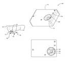
- FIG. 1is a perspective view of a schematic representation of a shear feedback system in accordance with an embodiment of the invention.
- FIG. 2is a partially sectioned view side of a compact tactile shear feedback device in accordance with one embodiment of the invention.
- FIG. 3includes two schematic views illustrating exemplary manners of actuating the shear tactor of the present invention.
- FIG. 4is a schematic view illustrating the components of a compact tactile shear feedback device in accordance with an embodiment of the invention.
- FIG. 5is a schematic view of an exemplary sensing system in accordance with one aspect of the invention.
- FIG. 6is a schematic view of an exemplary control/sensing system in accordance with one aspect of the invention.
- FIG. 7is a schematic view of an exemplary actuated tactor assembly in accordance with one aspect of the invention.
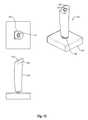
- FIG. 8is a schematic representation of an application of the present invention in use with a finger well.
- FIG. 9is a schematic representation of an application of the present invention with a tactor capable of selectively breaking contact with the skin surface (the skin surface shown is a portion of a finger or a palm in this example).
- FIG. 10is a schematic representation of an application of the present invention in use with finger wells coupled to or integrated with a stylus.
- FIG. 11illustrates an application of the present invention incorporated into a steering wheel
- FIG. 12illustrates an application of the present invention as incorporated into an ambulatory assist application (e.g., walking cane).
- an ambulatory assist applicatione.g., walking cane
- FIG. 13illustrates an embodiment of a multidirectional controller with shear feedback, including a saddle-configured well (thumb saddle), having a hand-controlled movable body and one actuated tactor assembly disposed on the movable body.
- a saddle-configured wellincluding a hand-controlled movable body and one actuated tactor assembly disposed on the movable body.
- FIG. 14illustrates an embodiment of a multidirectional controller with shear feedback, having a hand-controlled movable body and one actuated tactor assembly disposed on the side of the movable body.
- FIG. 15illustrates an embodiment of a multidirectional controller with shear feedback, having a hand-controlled movable body and multiple tactor assemblies disposed on the movable body, wherein the tactors may contact the user's thumb, palm, and/or finger(s).
- FIG. 16illustrates an embodiment of a multidirectional controller with shear feedback, having thumb- or finger-controlled movable bodies and one or more actuated tactor assemblies disposed on the movable bodies and/or on a stationary body.
- FIG. 17illustrates an embodiment of a multidirectional controller with shear feedback, having thumb- or finger-controlled movable bodies, thumb saddles, and one or more actuated tactor assemblies disposed on the movable bodies and/or on a stationary body.
- FIGS. 18A and 18Billustrate an embodiment of a mechanism for centering a movable body disposed on a gimbal.
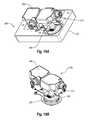
- FIG. 19illustrates an embodiment of an actuated tactor assembly having a force and/or displacement sensor(s).
- FIGS. 19A and 19Billustrate an embodiment of an actuated tactor assembly having a force and/or displacement sensor(s), with the outer housing removed to show details of the actuation mechanism.
- FIG. 20illustrates a mobile device controller dock, which utilizes two actuated tactor assemblies, each having a force and/or displacement sensor(s).
- Shear feedbackis the application of force that results in stretching or pulling (or possibly pinching) of a user's skin. Such application of force will tend to generate tensile stress on a trailing edge of the skin being targeted (“target area”) and a compressive stress on a leading edge of the skin. If pinching of the skin occurs, this increases compressive stresses on the leading edge of the skin. Shear forces can also be applied to the skin while sliding a tactor across the skin (i.e., with some slip between the tactor and the targeted skin).
- shear forcesis distinct from application of kinesthetic forces, as that term is understood by those of ordinary skill in the art.
- the application of shear force to a user's finger pad by moving a shear plate transverse to the user's finger padis to be distinguished from the kinesthetic forces and motions experienced by a user as a stylus or other device is applied to a user's fingers or hand causing (or tending to cause) motion of the finger, hand, and/or arm joints.
- Local shear deformations in the skin from moving a shear plate transverse to the user's skinare also distinct from the forces experienced by a user when a device is merely vibrated to provide information to a user.
- a shear forcerequires relative movement of the user's target skin area (e.g., finger pad or palm) relative to a shear plate, which relationship can occur by way of movement of the target skin area, movement of the shear plate, or both.
- target skin areae.g., finger pad or palm
- shear platee.g., a shear plate
- relative transverse movementis required to apply the shear force that is reacted locally, whereas application of kinesthetic forces can be realized without locally reacted relative transverse motion, since the kinesthetic forces are reacted away from the target area of the skin.
- a multidirectional controllergenerally, is a device that a user can manipulate in order to send signals or instructions to a controlled object. These signals or instructions may be communicated through mechanical or electromechanical means.
- a multidirectional controllermay have purely mechanical connections to the controlled object.
- a multidirectional controllermay have mechanical links that exert force directly or indirectly (e.g., through a hydraulic system) on the controlled object.
- a mechanical multidirectional controllerinclude a stick shift (also known as gear stick) that is used to shift between gears of a manual transmission and a steering wheel of an automobile.
- An electromechanical multidirectional controllermay first send signals or instructions to a computer system, which subsequently translates them to the controlled object.
- a common example of an electromechanical multidirectional controlleris a joystick used in numerous applications, for example in video games.
- a computer systemshall refer to any system or device capable of receiving, processing, and outputting electrical signals. Examples of common computer systems include personal computers, vehicle computers, machine automation controllers (e.g., controllers capable of sending instructions to servo or step motors), game consoles, and mobile devices (e.g., mobile phones, personal digital assistants, handheld video game systems).
- Isolating an area of the user's skin adjacent to the target areais particularly challenging when the target area is on a part of the user's body that is in motion during the transmission of the shear feedback.
- a finger on the user's hand that is in the process of manipulating a multidirectional controllermay move during the process and lose contact with the shear feedback mechanism.
- motion of a shear feedback mechanismmay dislodge the user's finger from the controller or, alternatively, move the controller away from the user's finger.
- Such motionmay result not only in loss of information sent via a shear feedback mechanism but also in an unwanted motion of the controller with respect to the user's hand and/or an unwanted command sent through the controller.
- Some of the devices described hereinare configured to restrain a portion of the user's skin adjacent to the target area, in order to improve the connection between the device and user's skin, and to better facilitate the saliency of shear feedback. Additionally, some of the described embodiments relate to restraining one or more target areas of the user's skin while the user is manipulating the multidirectional controller. Furthermore, some of the described devices, and their obvious variants, can provide shear feedback in one or more direction and on one or more target area of the user's skin.
- adjacent portion of the skincan be immediately adjacent the target area of skin or the portion of the skin and may be relatively far removed from the target area.
- the term “well”refers to a type of restraint that may be used to immobilize an area of a user's skin that is adjacent to the skin in contact with a tactor.
- a wellincludes a window or other orifice through which a contact with a tactor can be felt by a user's skin. Immobilizing the user's skin provides enhances the sensation experienced by the user.
- a wellprovides restraint without preventing a user from removing their hand from the restraint, as might occur if strapping a device to a user's hand. Examples of wells include but are not limited to a thumb well, finger well, and palm well, which are described in more detail below.
- a saddle-like structuremay also be used in combination with a well to produce a “saddle-configured well,” which can provide improved connectivity between the user's skin and a shear display device. Additionally, simply gripping a device, within which a moving tactor assembly is embedded, can also provide restraint to a user's skin, as a substitute for or in addition to a well.
- an actuated tactor assembly 100can include a tactor 110 that can be suitable for engaging a target area of a user's skin 120 .
- the target area of the skinin this example being the pad of a finger in immediate contact with the tactor 110 .
- a userexperiences the sensation of a shear force or stroking motion being applied to the user's skin.
- the force applied to the user's skinis applied primarily in a transverse direction.
- the force applied to the user's skinwill generally be in a direction indicated by the arrows. However, application along other directions is also possible.
- Tactile feedbackcan be provided to a person's finger tip, hand, or other body surface in the form of shear motions and forces that can be sensed by cutaneous touch receptors of the skin.
- the tactorcan be stroked or slid over the finger or other surfaces of the body; shear motions and forces induce skin stretch, which results in increased perceived sensation.
- the systemincludes the tactor 110 , and a base 130 .
- the basecan be configured to be coupled to an external support structure over which, or adjacent to which, the user can place his or her finger.
- the base 130is coupled to a thimble structure 140 that can be mountable over a finger of the user's hand.
- An actuation system 150can move the tactor 110 relative to the target area of the skin 120 .
- the tactor 110can comprise a tactor pad 111 and rod 160 , which rests in a spherical bearing 170 , and can be actuated by Shape Memory Alloy (“SMA”) devices known to those of ordinary skill in the art.
- SMAShape Memory Alloy
- the tactor 110can be coupled to a bearing plate 180 that can be moved to achieve movement of the tactor 110 .
- the bearing plate 180can be supported by parallel plates that form a bearing housing 190 .
- various springsshown with spring constants “k”
- SMA devicescoordinate to achieve movement of the tactor.
- the embodiments illustrated as cross-sectional views in FIGS. 4 and 7are similar in operation, with embodiment shown in FIG. 7 including one or more pulleys 230 , which enable(s) the use of SMA, while limiting overall size of the package of the system.
- Piezoelectric actuators or electromagnetic motorscan be utilized in the actuation system; the use of Shape Memory Alloy (SMA) actuators is also particularly attractive from a packaging standpoint.
- SMAShape Memory Alloy
- the design of the shear feedback devicescan be miniaturized and optimized for two or three axes of motion.
- FIGS. 19 , 19 a , and 19 bAn embodiment of an actuated tactor assembly is portrayed in FIGS. 19 , 19 a , and 19 b , which utilizes servo motors 360 to actuate a sliding plate assembly 370 , and incorporates a force sensor 350 within the tactor 110 .
- actuation of the tactormay be implemented in a manner described in U.S. patent application Ser. No. 12/699,494 which is incorporated by reference herein in its entirety.
- the minimum motion capability for the devicecan be in the range of ⁇ 0.050 mm of motion on at least 1 axis.
- the range of motion ofcan be on the order of 0.05 mm to about 2 mm.
- the rangecan vary from a minimum of about 0.05 mm to about 1 mm.
- the motion of the tactor and the target area of skinis limited, restrained or restricted to less than 2 mm of total relative travel.
- the total relative travelis limited to 1 mm or less. In another embodiment, the total relative travel is limited to 5 mm or less.
- the tactor pad 111can have a variety of shapes and sizes and can include a substantially planar surface that contacts the target area or can include a rounded or curved or otherwise non-planar geometry.
- the tactor pad 111has a cylindrical shape with a substantially hemispherical top surface, which contacts the target area of the skin 120 .
- the top surface of the tactor pad 111can be smooth, textured, or patterned with embossments and dimples of various shapes.
- the tactor pad's top surfacecan be made of various materials known to those skilled in the art (e.g., nylon, polystyrene, neoprene, or other thermoplastic or thermosetting materials or elastomers) to facilitate a desired coefficient of friction, texture, feel, durability, and manufacturability of the tactor pad and/or its top surface.
- materials known to those skilled in the arte.g., nylon, polystyrene, neoprene, or other thermoplastic or thermosetting materials or elastomers
- the target area of the skin 120can be sufficiently large to cause the user to experience the sense of shear forces acting on the target area. While the size of the target area of the skin 120 may vary, it must generally be large enough so that the user experiences more than a mere touching sensation; the user should be able to feel and discern that a shear force (or alternately they may discern a pinching of the skin) is being applied to the skin.
- the width or diameter of the tactor 110 and/or tactor pad 111can be about 3 mm. In other implementations, the tactor 110 and/or tactor pad 111 can be about 7 mm. Additionally, in some embodiments, the diameter can be 15 mm.
- the width of the tactor 110 and/or tactor pad 111can be greater than the height of the tactor 110 and/or tactor pad 111 , respectively.
- the distance from the bottom of the base 130 to the top surface of the tactor pad 111i.e., the height of the device
- the heightcan be about 38 mm.
- a total package size of the devicecan be about 35 mm ⁇ 35 mm.
- FIG. 5illustrates an exemplary manner in which movement of the system can be measured using various emitters 210 and detectors 220 .
- the pairs of emitter and detectorscan register the movement and can provide a corresponding signal to a computer system (not shown).
- This conceptmay be incorporated into the control/sensing system of FIG. 6 .
- This embodimentutilizes principles similar to those outlined above, with the addition of a pair of springs opposing each SMA device to limit potential rotation of the bearing plate 180 during translational movement to reduce the potential of incorrect readings by the detectors 220 and emitters 210 .
- the shear forcecan be applied in a variety of movement patterns.
- the shear forcecan be applied intermittently, such that it would create a sensation of a stroking motion that may indicate direction.
- the tactor 110can be moved once in one direction or can be moved back-and-forth, with the movement one direction possibly differing in some aspect from the movement in the opposite direction.
- the tactor 110can be moved in one direction at a relatively high rate and “returned” to a null position by moving in the opposite direction at a relatively slower, less perceptible rate. This movement pattern can be repeated multiple times to provide the operator with the greatest opportunity to sense and correctly interpret the information being provided.
- Other exemplary movement patternscan include moving the tactor 110 in one direction while the tactor and the target area of skin 120 are in contact, then breaking contact between the target area of skin and the pad to return the pad to a null position.
- This aspect of the inventionis illustrated by example in FIG. 9 , where tactor 110 can move laterally to apply the shear force to the target area of skin 120 , after which it can move normal to the skin (i.e., it can break contact with the skin), and return to a null position. Then, contact with the skin can be made again, and the shear force can again be applied to the skin (at either the same magnitude, velocity, etc., or at a differing magnitude, velocity, etc.).
- the userdoes not necessarily sense the return movement of the pad, which otherwise may cause confusion on the direction being indicated.
- Contact between the tactor pad 111 and the target area of the skin 120can be broken by either moving the pad normal to (and away from) the target area of skin, or by moving the target area of skin normal to (and away from) the tactor.
- the effect of a stroking motioncan also be achieved by actively varying the effective coefficient of friction of the tactor by vibrating the tactor with ultrasonic vibrations.
- the tactor 110may be moved in one direction at a relatively high friction level, and “returned” to a null position by moving in the opposite direction at a relatively lower, less perceptible friction level. This shear force or motion application pattern can be repeated to provide the operator with the greatest opportunity to sense and correctly interpret the information being provided.
- the shear force or motion application patterncan be varied depending on the urgency of the information being conveyed to the user. For example, “non-critical” information can be provided with a signal of relatively slower or shorter displacement(s) of the tactor relative to the target area of skin. Such may be the case, if information were being provided to an operator of a vehicle who had not disengaged a turn signal after making a turn. Alternatively, “critical” information can be provided by a motion pattern with relatively increased magnitude or speed of the movement of the tactor 110 .
- one or more actuated tactor assemblycan provide non-directional information or combination information, such as information consisting of multiple components.
- a motion patternas described above, may provide information about the speed of a moving object (whether real or virtual) by alternating movements and the speed of the movements of a tactor. Additionally, direction of those movements may indicate the direction of the moving object. It is appreciated that other movement patterns may be used to indicate the speed of a moving object; for example, vibratory feedback through the tactor may also provide information about the speed of a moving object.
- the usermay be trained to recognize and/or be able to estimate the speed of a moving object based on the tactile shear feedback pattern provided by the tactor.
- Information of a given magnitudesuch as temperature, pressure, or altitude, may also be communicated through the position of the tactor. If the information to be communicated is vector-like in nature, that is it possesses a direction and magnitude, the scaled direction and magnitude of the tactor's position can be used to directly convey such information.
- Other non-directional informationmay also be conveyed to a user through tactor movement patterns. Examples of such information include information about surface roughness, vibrations, impact, warnings, completion of a task, and requests.
- the inventioncan be used to provide tactile feedback and to be used in combination with a commercial 3-D force feedback device, such as one sold under the trade name PHANToM, made by SensAble Technologies, or other similar commercial force feedback devices.
- a commercial 3-D force feedback devicesuch as one sold under the trade name PHANToM, made by SensAble Technologies, or other similar commercial force feedback devices.
- the inventioncan be used to replace PHANToM's current thimble interface.
- the shear feedback devicecan be added to enhance (or replace) the data input device used as the common computer “mouse.”
- the shear feedback devicecan be used in combination with a finger-based touchpad and can be used to represent the current location of the computer cursor.
- the devicecould be used to transmit shearing motions to the skin of the fingerpad to suggest which direction the user should move their finger to attend to a particular task or application, thus providing attention cueing capability to the user.
- the shear feedback devicecan be added to many current devices, and is suitable for applications in wearable or mobile computing. For example, it can be used as part of a gaming controller interface.
- the deviceis also well suited for applications which require communication of directional information. An example of this includes embedding several shear feedback device devices into a steering wheel to communicate information from a navigation system. The shearing force exerted on the user's skin in each of these applications can provide suggested direction cues to greatly enhance the ability of the user to operate the vehicle.
- FIG. 8illustrates an embodiment of the invention that incorporates a well 250 including a recess 260 into a restraining structure 240 .
- FIG. 8depicts a well used specifically for restraining the motion of a finger, i.e., it is a finger well.
- a tactor 110can be located or disposed within or adjacent to the well 250 .
- the well 250can serve as an indicator of the location of the tactor 110 , so that a user can locate the tactor by touch. However, the well 250 need not coincide with the location of the tactor 110 .
- the well 250also serves as a restraining structure that restrains portions of the user's skin adjacent the target area of the skin 120 , to better transmit shear forces to the target area.
- the wellitself can also be independently actuated in two-dimensions relative to the restraining structure 240 (similar to the embodiment illustrated in FIG. 9 , except that the well would move instead of, or in addition to, the tactor).
- the restraint structure 240 with which the well 250 can be associatedcan vary widely.
- two wells 250are incorporated into a stylus 265 to enable tactors 110 to provide directional instruction or information to the user of the stylus.
- FIG. 11illustrates an exemplary application of the present invention in use on a vehicle.
- the well 250can be installed on (or in) a steering wheel 270 to enable a tactor 110 or multiple tactors to provide directional commands to a driver through a tactile interface.
- the shear feedback deviceis indicated as installed in a location on the steering wheel facing the driver.
- the shear feedback devicewill be installed on (or in) the steering wheel so as to face the dashboard and be accessible by fingertips of the user that are wrapped about the rear of the steering wheel.
- the shear feedback devicecan be utilized to provide tactile information to the user relating to a variety of differing aspects of operating the vehicle, including information relating to a direction of travel of the vehicle (including a direction of travel different than a present direction of travel), speed of the vehicle, and an incoming call on a vehicle communications device.
- any type of information typically provided by way of auditory or visual stimuluscan be presented to the vehicle's operator via the present shear feedback device.
- the well 250can be incorporated into a walking cane 280 utilized by the visually impaired to enable the actuated tactor assembly 100 to provide directional commands through a tactile interface, possibly alerting the visually-impaired user of the presence of an upcoming obstacle (and/or directing the user around the obstacle).
- the inventionmay be a multidirectional controller with shear feedback 300 , comprising a stationary body 310 , a movable body 320 , and an actuated tactor assembly 100 , which can be placed into contact with a target area of the skin 120 .
- the stationary body 310can be any fixed or non-fixed object or device that is able to provide physical support to and/or have a physical connection with the movable body 320 , such that the movable body has at least one degree of freedom of motion with respect to the stationary body.
- a stationary bodymay also be any fixed or non-fixed device that is able to ascertain the location or change in the location of the movable body, whether independently, through interaction with the movable body, or through interaction with a movable body and at least one other device.
- a multidirectional controllermay be a joystick (whether purely mechanical or electromechanical), game controller, a steering wheel, and/or a gear shifter.
- a stationary bodymay not be in physical connections with the movable body, such as in the video game system Wii, manufactured by Nintendo®, where the stationary body is the console, and the movable body is the wireless controller (also known as the Wii remote).
- a “stationary body”When a reference is made to a “stationary body,” it is intended to identify any object or device with respect to which relative speed and/or displacement of another object or device (e.g., a movable body or tactor) may be measured.
- a “stationary body”may not be fixed in space and may move freely.
- movements of a stationary bodymay be detected by an outside sensor.
- a stationary body 310 of a multidirectional controller with shear feedback 300as shown in FIGS. 16 and 17 , may be moved by a user, and a wired or wireless detector (not shown) may detect the speed and/or displacement of the stationary body 310 .
- movement of or force exerted on the movable body 320may be detected by at least one sensor 330 .
- the sensor 330may be disposed in the stationary body 310 or in the movable body 320 .
- a variety of sensors known to those skilled in the artcan be used to detect movement of or force exerted on the movable body 320 .
- a displacement transducercan be used to detect movement or displacement and a force gauge can be used to detect force exerted on the movable body.
- non-contact positioning sensorsas previously described, can also be used to detect movement or displacement of the movable body 320 .
- the moveable body 320may not be in physical contact with the stationary body 310 and/or sensor(s) 330 .
- a target area of the skin 120e.g., an area on a user's finger, thumb, or palm
- a target area of the skin 120can be placed in contact with the tactor 110 .
- multiple tactorscan be used to provide information to a user. Some of those mechanisms have been described above.
- the movable body 320 and/or the stationary body 310may provide haptic feedback (e.g., vibrotactile or force feedback) to a user.
- haptic feedbacke.g., vibrotactile or force feedback
- Means for providing such feedbackare well known to those skilled in the art.
- one or more actuated tactor assembly 100may receive movement instructions from one or more computer system.
- a movement instructionmay indicate distal displacement along one or more axis as well as the speed at which the tactor should travel along each axis.
- the actuated tactor assembly 100may comprise at least one sensor 350 , as shown in FIGS. 5 , 6 , 19 , 19 A, and 19 B, such as force and/or motion sensors, which may detect force exerted on or displacement of the tactor.
- a switchmay be incorporated into the actuated tactor assembly, to register when a user pushes down on the tactor, as shown in FIGS. 18B and 19B .
- one or more computer systemmay receive information from at least one sensor 350 , as shown in FIGS. 19 and 19A , and/or emitter 210 -detector 220 pairs, as shown in FIGS. 5 and 6 , indicating the force exerted on and/or displacement of one or more tactor 110 .
- a multidirectional controller with shear feedback 300also may be comprised of a movable body 320 , a stationary body 310 , an actuated tactor assembly 110 , as described above, and a well 250 , which may be designed to accommodate a target area of the skin 120 on the skin of the user's finger.
- the well 250may be designed to restrain the skin adjacent to the target area on the user's finger. Restraining the skin adjacent to the target area on the user's finger will improve transmission of the shear forces. Improved transmission of shear forces results in improved transmission of the information intended to be communicated to the user.
- a multidirectional controller with shear feedback 300may be comprised of a stationary body 310 , a movable body 320 , multiple tactor assemblies 100 , and one or more corresponding wells 250 .
- Tactors 110may be positioned to come into contact with one or more target areas on a user's skin.
- the one or more target areas 120may be located on a finger, thumb, palm, and/or wrist of the user. Advantages and the manner of restraining skin adjacent to the target area of the skin 120 are the same as described above in connection with the embodiments illustrated in FIGS. 13 and 14 .
- FIG. 15shows an additional tactor from those shown in FIGS.
- the movable body 320may have a well 250 .
- One or more tactor 110may be disposed within a well 250 .
- the top surface of a tactor 110 or tactor pad 111may protrude above or may be recessed below the bottom surface of the well 250 .
- the actuated tactor assembly 100 , tactor 110 , and/or tactor pad 111may be spring loaded, such as to be pressed against a target area when the skin adjacent to the target area is in contact with the well 250 .
- the multidirectional controller with shear feedback 300may comprise two thumb- or finger-controlled movable bodies 320 , and actuated tactor assemblies, with tactors 110 , which may be disposed within or accessible through the movable bodies 320 . Additionally or alternatively, tactors 110 may be disposed on the stationary body 310 and may come into contact with the user's fingers, thumbs, and/or palms.
- a multidirectional controller with shear feedback 300may comprise at least one stationary body 310 , a plurality of movable bodies 320 , and one or more actuated tactor assembly 100 , which can be disposed on the movable body 320 and/or stationary body 310 .
- one or more actuated tactor assembly 100may be disposed within gimbaled thumb joysticks or buttons (movable bodies 320 ), such that one or more target area of the skin 120 on user's thumbs or fingers comes into contact with at least one tactor 110 .
- one or more actuated tactor assembly 100may be disposed on the sides of the stationary body 310 , such that one or more target area of the skin 120 on the user's hands comes into contact with at least one tactor 110 .
- One or more actuated tactor assembly 100may also be placed on the bottom of the controller 300 , such that one or more target area of the skin 120 on the user's hands or fingers comes into contact with at least one tactor 110 .
- a movable body 320may be disposed in physical connection with a stationary body 310 , such that the movable body 320 has at least one degree of freedom of motion with respect to the stationary body 310 .
- a movable body 320may be disposed on a gimbal mounted on the stationary body 310 .
- Various ways of mounting and centering a gimbaled movable bodyare known to those skilled in the art. For example, a gimbal may be centered with the aid of torsion springs positioned concentrically with the axes of the gimbal's rotation.
- a gimbalmay be set in rotating rings 400 with bushings 390 , and may be centered with tension (or extension) springs 380 by retracting the centering elements 430 back toward the stop block 410 , when the gimbal has been moved off center.
- the bushings 390may be secured with cover plates 440 .
- a switch 420may be placed under the bushing 390 . The switch 420 may be engaged when the user presses down on the tactor 110 and/or movable body 320 . When engaged, the switch 420 may send a signal to a computer system.
- a multidirectional controller with shear feedback 300may also have one or more well 250 , configured to isolate a target area of the skin 120 that comes into contact with a tactor 110 disposed within the well, as described above.
- a multidirectional controller with shear feedback 300may further comprise a detector (not shown), capable of detecting speed, displacement, and/or change in location of the stationary body 310 .
- the well 250may be designed to restrain an area of the skin adjacent to the user's target area of the skin 120 .
- the well 250may be configured to restrain skin adjacent to a target area of the skin 120 on the user's finger and/or thumb. Additionally or alternatively, the well 250 may be configured to restrain a user's finger and/or thumb, such that a distal phalange, intermediate phalange, and/or proximal phalange is/are immobilized.
- Immobilizing the skin adjacent to the target area and/or the user's one or more phalangehelps to maintain user's target area in contact with the tactor as well as user's hand and/or finger in contact with the movable body.
- the well 250may be designed to immobilize the user's skin and/or one or more phalange to improve transmission of shear forces onto the target area, while eliminating or reducing unwanted motion of the movable body 320 and/or stationary body 310 in response to the movement of the tactor.
- the well 250also may be configured to include a thumb saddle, finger saddle, or palm saddle to aid the well to further prevent relative motion between the well and the user's thumb, finger, and palm, respectively.
- FIGS. 13 , 15 and 17show typical examples of saddle-configured thumb wells.
- the saddle configuration of the well 250may allow more surface area of the user's skin, which is adjacent to the target area, to come into contact with the well. Contact with additional surface area of the skin provides an improved restraint of the skin as well as improved control capabilities and comfort for the user.
- the saddle-configured well 250may be fitted around the user's thumb. In this configuration, the well 250 would restrain the skin adjacent to the target area as well as generally help maintain the user's thumb in contact with the movable body.
- the saddle-configured well 250may have one or more raised edges, such that the user's thumb or finger would be centered in a predetermined location.
- two opposing symmetrically raised edges of a substantially rectangular well 250would guide the user's thumb or finger toward the center of the well 250 .
- a tactor 110may be disposed in the center of the well 250 , to contact the user's skin when the user's thumb or finger is placed in contact with the well.
- a restraintmay be a well 250
- the skinalso may be restrained when the user grips the controller in a manner that would prevent the controller from moving in response to the movement of the tactor.
- the stationary body 310 in combination with the user's grip thereonfunction as a restraint and isolate the target area of the user's skin that is in contact with the tactor 110 for the tactors 110 that are on the sides of the stationary body 310 .
- the user's gripalso functions as a restraint to isolate the target area of the user's skin that is in contact with a tactor 110 on the side of the movable body 320 in FIG. 15 .
- a multidirectional controller with shear feedback 300which has more than one actuated tactor assembly, may provide directional information about a three-dimensional space.
- two of the tactor assemblies shown in FIG. 15one positioned to be in contact with a target area on the user's palm (or the one contacted by the finger) and another positioned to be in contact with a target area on the user's thumb, can provide such information about a three-dimensional space; one actuated tactor assembly may provide information related to X-axis and Y-axis, and the other actuated tactor assembly would provide information related to Y-axis and Z-axis; alternatively, one of the tactors may provide information only related to an axis that is not covered by the other tactor.
- a multidirectional controller with shear feedback 300which has more than one actuated tactor assembly, may convey different information types at specific tactor 110 locations. For example, as shown in FIGS. 16 and 17 , one could convey direction information concerning where a user should move with shear feedback direction cues on the tactor 110 on the left thumb joystick, while presenting information on where the user should look with shear feedback direction cues from the tactor 110 on the right thumb joystick. Furthermore, shear feedback from tactors 110 on the sides of these controllers could correspond to the health of a user's game character.
- the multidirectional controller with shear feedback 300may provide other information via variety of movement patterns described above.
- a multidirectional controller with shear feedback 300may comprise at least one stationary body 310 and one or more actuated tactor assembly 100 , as shown in FIGS. 16 , 17 , 19 and 20 .
- An actuated tactor assemblymay comprise a sensor 350 , capable of detecting force exerted on and/or displacement of the tactor 110 .
- a multidirectional controller with shear feedback 300may further comprise one or more well 250 .
- one or more actuated tactor assemblymay be disposed within one or more well 250 .
- one or more well 250may be configured to isolate the motion of a target area of the skin 120 to correspond to the motion of the tactor 110 , located within such well, as described above.
- the device depicted in FIG. 20can utilize force inputs from the user to reposition the location of each tactor 110 .
- the motion of a tactor 110could be programmed to imitate natural phenomena such as a spring, damper, inertia, or a collision.
- Tactile shear display direction (or other) cuescan be superimposed on top of the above programmed tactor behavior, hence creating a hybrid of tactor behaviors.
- the useris able to maintain proper finger/thumb restraint, for the communication of the provided tactile cues, by maintaining contact between their thumb and some portion of the thumb well 250 .
- Various actuatorsmay be used to generate movement of the tactor 110 .
- servo motors 360 or stepper motorsmay be used to move the tactor 110 .
- a movable stage 370may be used in connection with the motors 360 and the tactor 110 .
- the motors 360may be controlled by a computer system (not shown).
Landscapes
- Engineering & Computer Science (AREA)
- General Engineering & Computer Science (AREA)
- Theoretical Computer Science (AREA)
- Multimedia (AREA)
- Human Computer Interaction (AREA)
- Physics & Mathematics (AREA)
- General Physics & Mathematics (AREA)
- User Interface Of Digital Computer (AREA)
- Position Input By Displaying (AREA)
- Switches With Compound Operations (AREA)
Abstract
Description
Claims (26)
Priority Applications (3)
| Application Number | Priority Date | Filing Date | Title |
|---|---|---|---|
| PCT/US2011/055633WO2012048325A2 (en) | 2010-10-08 | 2011-10-10 | A multidirectional controller with shear feedback |
| US13/269,948US9268401B2 (en) | 2007-07-30 | 2011-10-10 | Multidirectional controller with shear feedback |
| US15/043,112US10191549B2 (en) | 2007-07-30 | 2016-02-12 | Multidirectional controller with shear feedback |
Applications Claiming Priority (5)
| Application Number | Priority Date | Filing Date | Title |
|---|---|---|---|
| US96264907P | 2007-07-30 | 2007-07-30 | |
| US12/182,906US9285878B2 (en) | 2007-07-30 | 2008-07-30 | Shear tactile display system for communicating direction and other tactile cues |
| US40481110P | 2010-10-08 | 2010-10-08 | |
| US40480810P | 2010-10-08 | 2010-10-08 | |
| US13/269,948US9268401B2 (en) | 2007-07-30 | 2011-10-10 | Multidirectional controller with shear feedback |
Related Parent Applications (1)
| Application Number | Title | Priority Date | Filing Date |
|---|---|---|---|
| US12/182,906Continuation-In-PartUS9285878B2 (en) | 2007-07-30 | 2008-07-30 | Shear tactile display system for communicating direction and other tactile cues |
Related Child Applications (1)
| Application Number | Title | Priority Date | Filing Date |
|---|---|---|---|
| US15/043,112ContinuationUS10191549B2 (en) | 2007-07-30 | 2016-02-12 | Multidirectional controller with shear feedback |
Publications (2)
| Publication Number | Publication Date |
|---|---|
| US20120038468A1 US20120038468A1 (en) | 2012-02-16 |
| US9268401B2true US9268401B2 (en) | 2016-02-23 |
Family
ID=45928492
Family Applications (2)
| Application Number | Title | Priority Date | Filing Date |
|---|---|---|---|
| US13/269,948Expired - Fee RelatedUS9268401B2 (en) | 2007-07-30 | 2011-10-10 | Multidirectional controller with shear feedback |
| US15/043,112Expired - Fee RelatedUS10191549B2 (en) | 2007-07-30 | 2016-02-12 | Multidirectional controller with shear feedback |
Family Applications After (1)
| Application Number | Title | Priority Date | Filing Date |
|---|---|---|---|
| US15/043,112Expired - Fee RelatedUS10191549B2 (en) | 2007-07-30 | 2016-02-12 | Multidirectional controller with shear feedback |
Country Status (2)
| Country | Link |
|---|---|
| US (2) | US9268401B2 (en) |
| WO (1) | WO2012048325A2 (en) |
Cited By (3)
| Publication number | Priority date | Publication date | Assignee | Title |
|---|---|---|---|---|
| US20160358428A1 (en)* | 2014-02-13 | 2016-12-08 | University Of Utah Research Foundation | Compliance tactile feedback device |
| US10324530B2 (en)* | 2015-12-14 | 2019-06-18 | Facebook Technologies, Llc | Haptic devices that simulate rigidity of virtual objects |
| US11150731B2 (en)* | 2018-09-28 | 2021-10-19 | Apple Inc. | Multi-modal haptic feedback for an electronic device using a single haptic actuator |
Families Citing this family (38)
| Publication number | Priority date | Publication date | Assignee | Title |
|---|---|---|---|---|
| US9285878B2 (en) | 2007-07-30 | 2016-03-15 | University Of Utah Research Foundation | Shear tactile display system for communicating direction and other tactile cues |
| US9268401B2 (en) | 2007-07-30 | 2016-02-23 | University Of Utah Research Foundation | Multidirectional controller with shear feedback |
| US8610548B1 (en) | 2009-02-03 | 2013-12-17 | University Of Utah Research Foundation | Compact shear tactile feedback device and related methods |
| US8994665B1 (en) | 2009-11-19 | 2015-03-31 | University Of Utah Research Foundation | Shear tactile display systems for use in vehicular directional applications |
| US8890016B2 (en)* | 2010-12-21 | 2014-11-18 | Stilotech Inc. | Touch pad device |
| EP2862151A4 (en)* | 2012-06-13 | 2016-01-13 | Univ Utah Res Found | FEATHER FEEDBACK FEEDBACK DEVICES, SYSTEMS, AND METHODS |
| US9317123B2 (en) | 2012-06-13 | 2016-04-19 | University Of Utah Research Foundation | Skin stretch feedback devices, systems, and methods |
| TWI573041B (en)* | 2012-09-18 | 2017-03-01 | 廣達電腦股份有限公司 | Input device and electronic device |
| JP6851197B2 (en)* | 2013-05-30 | 2021-03-31 | ティーケー ホールディングス インク.Tk Holdings Inc. | Multidimensional trackpad |
| EP3014394B1 (en) | 2013-07-05 | 2022-06-22 | Rubin, Jacob A. | Whole-body human-computer interface |
| WO2015054362A1 (en) | 2013-10-08 | 2015-04-16 | Tk Holdings Inc. | Force-based touch interface with ingrated multi-sensory feedback |
| WO2015179730A1 (en) | 2014-05-22 | 2015-11-26 | Tk Holdings Inc. | Systems and methods for shielding a hand sensor system in a steering wheel |
| DE112015002601T5 (en) | 2014-06-02 | 2017-05-04 | Tk Holdings Inc. | Systems and methods for printing sensor circuits on a sensor mat for a steering wheel |
| US10466826B2 (en) | 2014-10-08 | 2019-11-05 | Joyson Safety Systems Acquisition Llc | Systems and methods for illuminating a track pad system |
| US9946350B2 (en) | 2014-12-01 | 2018-04-17 | Qatar University | Cutaneous haptic feedback system and methods of use |
| WO2016148182A1 (en)* | 2015-03-18 | 2016-09-22 | 株式会社ニコン | Electronic device and program |
| JP6625726B2 (en) | 2016-03-04 | 2019-12-25 | 株式会社ソニー・インタラクティブエンタテインメント | Control device and control program |
| US10336361B2 (en) | 2016-04-04 | 2019-07-02 | Joyson Safety Systems Acquisition Llc | Vehicle accessory control circuit |
| WO2018017835A1 (en) | 2016-07-20 | 2018-01-25 | Tk Holdings Inc. | Occupant detection and classification system |
| JP6626576B2 (en) | 2016-07-21 | 2019-12-25 | 株式会社ソニー・インタラクティブエンタテインメント | Operation device and control system |
| US11344797B2 (en) | 2016-07-26 | 2022-05-31 | Sony Interactive Entertainment Inc. | Information processing system, operation device, and operation device control method with multi-mode haptic feedback |
| EP3493030B1 (en) | 2016-07-26 | 2021-06-23 | Sony Interactive Entertainment Inc. | Operation device and operation device control method |
| WO2018042716A1 (en)* | 2016-08-31 | 2018-03-08 | アルプス電気株式会社 | Operation device |
| WO2018057898A1 (en)* | 2016-09-23 | 2018-03-29 | Arizona Board Of Regents On Behalf Of Arizona State University | Device for providing cutaneous sensations to a fingertip |
| US9741216B1 (en) | 2016-10-14 | 2017-08-22 | Oculus Vr, Llc | Skin stretch instrument |
| US11211931B2 (en) | 2017-07-28 | 2021-12-28 | Joyson Safety Systems Acquisition Llc | Sensor mat providing shielding and heating |
| WO2019064518A1 (en) | 2017-09-29 | 2019-04-04 | 株式会社ソニー・インタラクティブエンタテインメント | Operation device and control apparatus therefor |
| JP6949982B2 (en) | 2017-10-27 | 2021-10-13 | 株式会社ソニー・インタラクティブエンタテインメント | Operation device |
| US10809804B2 (en)* | 2017-12-29 | 2020-10-20 | Haptx, Inc. | Haptic feedback glove |
| US11009955B2 (en)* | 2018-07-30 | 2021-05-18 | Apple Inc. | Stylus with shear force feedback |
| US10838486B2 (en) | 2019-02-28 | 2020-11-17 | Microsoft Technology Licensing, Llc | Virtual reality controller |
| US11422629B2 (en) | 2019-12-30 | 2022-08-23 | Joyson Safety Systems Acquisition Llc | Systems and methods for intelligent waveform interruption |
| US11260297B2 (en) | 2020-05-01 | 2022-03-01 | Dell Products L.P. | Information handling system wheel input device |
| US11439902B2 (en)* | 2020-05-01 | 2022-09-13 | Dell Products L.P. | Information handling system gaming controls |
| EP4232886B1 (en) | 2020-10-22 | 2025-09-17 | Haptx, Inc. | Actuator system for force feedback exoskeleton |
| US11079249B1 (en)* | 2020-12-14 | 2021-08-03 | International Business Machines Corporation | Haptic navigation device |
| WO2024077399A1 (en)* | 2022-10-13 | 2024-04-18 | Innovobot Labs Inc. | Haptic device with multiple haptic modalities |
| GB2636390A (en)* | 2023-12-11 | 2025-06-18 | Cambridge Mechatronics Ltd | Joystick assembly and button |
Citations (115)
| Publication number | Priority date | Publication date | Assignee | Title |
|---|---|---|---|---|
| US4540979A (en) | 1982-09-28 | 1985-09-10 | Gerger Edward J | Grip-responsive operator alertness monitor |
| US4591868A (en) | 1982-04-09 | 1986-05-27 | National Industries, Inc. | Collapsible motor operated antenna |
| US5028093A (en) | 1989-05-11 | 1991-07-02 | Nason Robert A | Protective lubricating cap |
| US5184319A (en) | 1990-02-02 | 1993-02-02 | Kramer James F | Force feedback and textures simulating interface device |
| US5261266A (en) | 1990-01-24 | 1993-11-16 | Wisconsin Alumni Research Foundation | Sensor tip for a robotic gripper and method of manufacture |
| US5273384A (en) | 1992-09-22 | 1993-12-28 | Dunbar Max E | Thread protecting device |
| US5451924A (en) | 1993-01-14 | 1995-09-19 | Massachusetts Institute Of Technology | Apparatus for providing sensory substitution of force feedback |
| US5587937A (en) | 1993-10-01 | 1996-12-24 | Massachusetts Institute Of Technology | Force reflecting haptic interface |
| US5589828A (en) | 1992-03-05 | 1996-12-31 | Armstrong; Brad A. | 6 Degrees of freedom controller with capability of tactile feedback |
| US5631861A (en) | 1990-02-02 | 1997-05-20 | Virtual Technologies, Inc. | Force feedback and texture simulating interface device |
| US5694013A (en) | 1996-09-06 | 1997-12-02 | Ford Global Technologies, Inc. | Force feedback haptic interface for a three-dimensional CAD surface |
| US5709219A (en) | 1994-01-27 | 1998-01-20 | Microsoft Corporation | Method and apparatus to create a complex tactile sensation |
| US5721405A (en) | 1996-03-12 | 1998-02-24 | Kabushiki Kaisha Tokai Rika Denki Seisakusho | Tactile feedback mechanism for a multidirectional switch |
| US5752795A (en) | 1997-01-21 | 1998-05-19 | D'adamo; Bruce | Apparatus and method for protecting exposed sections of a nut and bolt |
| US5767796A (en) | 1995-10-19 | 1998-06-16 | U.S Philips Corporation | Navigation system for a vehicle |
| US5765791A (en) | 1997-01-29 | 1998-06-16 | Givonetti; Raymond R. | Hand rest for an easel |
| US5786997A (en) | 1995-06-20 | 1998-07-28 | Ziba Design, Inc. | Capacitively coupled multiple axis data input apparatus and method |
| US5982696A (en) | 1996-06-06 | 1999-11-09 | Cirrus Logic, Inc. | Memories with programmable address decoding and systems and methods using the same |
| US6042555A (en) | 1997-05-12 | 2000-03-28 | Virtual Technologies, Inc. | Force-feedback interface device for the hand |
| US6135691A (en) | 1996-02-09 | 2000-10-24 | Romilly International Ltd. | Protective caps for bolts with nuts |
| US6158933A (en) | 1999-12-30 | 2000-12-12 | Nicholson; Orv | Dirt cap device for visually indicating rotation of a fastener and for keeping the fastener clean |
| US6184868B1 (en) | 1998-09-17 | 2001-02-06 | Immersion Corp. | Haptic feedback control devices |
| US6208328B1 (en) | 1997-03-07 | 2001-03-27 | International Business Machines Corporation | Manipulative pointing device, and portable information processing apparatus |
| KR200222674Y1 (en) | 2000-11-23 | 2001-05-15 | 성성진 | Computer input unit |
| US6236306B1 (en) | 1997-05-05 | 2001-05-22 | Lyndon L. Liebelt | Tactual annunciating device for notifying vehicle or machinery status or condition |
| US6246391B1 (en) | 1998-12-01 | 2001-06-12 | Lucent Technologies Inc. | Three-dimensional tactile feedback computer input device |
| WO2001091100A1 (en) | 2000-05-24 | 2001-11-29 | Immersion Corporation | Haptic devices using electroactive polymers |
| US6330837B1 (en) | 1997-08-28 | 2001-12-18 | Microdexterity Systems, Inc. | Parallel mechanism |
| US20010052893A1 (en) | 1998-11-10 | 2001-12-20 | Lord Corporation | Magnetically-controllable, semi-active haptic interface system and apparatus |
| US20020033795A1 (en) | 2000-01-19 | 2002-03-21 | Shahoian Erik J. | Haptic interface for laptop computers and other portable devices |
| US6388655B1 (en) | 1999-11-08 | 2002-05-14 | Wing-Keung Leung | Method of touch control of an input device and such a device |
| US20020068605A1 (en)* | 2000-08-03 | 2002-06-06 | Stanley Winfield Scott | Manual mobile-communication interface |
| US6418362B1 (en) | 2000-10-27 | 2002-07-09 | Sun Microsystems, Inc. | Steering wheel interface for vehicles |
| US6417638B1 (en) | 1998-07-17 | 2002-07-09 | Sensable Technologies, Inc. | Force reflecting haptic interface |
| US20020145512A1 (en) | 1998-05-18 | 2002-10-10 | Sleichter Charles G. | Vibro-tactile alert and massaging system having directionally oriented stimuli |
| US6494658B1 (en) | 2001-03-23 | 2002-12-17 | Guy L. Roy | Corrosion-resisting protector cap |
| US20030016207A1 (en) | 1995-11-30 | 2003-01-23 | Immersion Corporation | Tactile feedback man-machine interface device |
| US6535806B2 (en) | 2001-01-30 | 2003-03-18 | Delphi Technologies, Inc. | Tactile feedback control for steer-by-wire systems |
| US6565059B1 (en) | 2002-04-09 | 2003-05-20 | Leonard S. Falconer | Hand rest for an artist's easel |
| US20040010346A1 (en) | 2002-07-11 | 2004-01-15 | Stewart Paul Joseph | Method of real-time collision detection between solid geometric models |
| US20040025624A1 (en) | 2002-08-12 | 2004-02-12 | Trw Automotive Safety Systems Gmbh | Vehicle steering wheel and safety system |
| US6693622B1 (en) | 1999-07-01 | 2004-02-17 | Immersion Corporation | Vibrotactile haptic feedback devices |
| US6691972B1 (en) | 2003-02-05 | 2004-02-17 | William E. Oliver | Adjustable handrest for artists |
| US6693516B1 (en)* | 1999-05-10 | 2004-02-17 | Vincent Hayward | Electro-mechanical transducer suitable for tactile display and article conveyance |
| US20040040805A1 (en) | 2000-10-27 | 2004-03-04 | Bailey Ralph-Peter Steven | Haptic input devices |
| US6703999B1 (en) | 2000-11-13 | 2004-03-09 | Toyota Jidosha Kabushiki Kaisha | System for computer user interface |
| US20040060807A1 (en) | 2002-08-27 | 2004-04-01 | Takumi Nishimoto | Multidirectional input device |
| US20040095369A1 (en) | 2002-11-18 | 2004-05-20 | Fuji Xerox Co., Ltd. | Haptic interface device |
| US20040106916A1 (en) | 2002-03-06 | 2004-06-03 | Z-Kat, Inc. | Guidance system and method for surgical procedures with improved feedback |
| US20040104887A1 (en)* | 2002-11-29 | 2004-06-03 | Fuji Xerox Co., Ltd. | Haptic interface device |
| US20040117084A1 (en) | 2002-12-12 | 2004-06-17 | Vincent Mercier | Dual haptic vehicle control and display system |
| US20040129552A1 (en) | 2002-11-19 | 2004-07-08 | Yoshiyuki Nakade | Multidirectional operation switch |
| WO2003012557A9 (en) | 2001-07-31 | 2004-08-12 | Immersion Corp | Control wheel with haptic feedback |
| US6788999B2 (en) | 1992-01-21 | 2004-09-07 | Sri International, Inc. | Surgical system |
| US6793234B2 (en) | 2001-10-17 | 2004-09-21 | Meritor Light Vehicle Technology, Llc | Steering wheel feedback mechanism |
| US6808350B1 (en) | 2003-01-27 | 2004-10-26 | Norman L. Tooman | Anchor bolt cap and method of use |
| US20040227727A1 (en) | 1995-11-17 | 2004-11-18 | Schena Bruce M. | Force feedback device including actuator with moving magnet |
| US20040237669A1 (en) | 2003-05-29 | 2004-12-02 | Vincent Hayward | Method and apparatus to record and reproduce tactile sensations |
| US20050021190A1 (en) | 2003-07-24 | 2005-01-27 | Worrell Barry C. | Method and apparatus for accessing vehicle systems |
| US6859819B1 (en) | 1995-12-13 | 2005-02-22 | Immersion Corporation | Force feedback enabled over a computer network |
| US20050052415A1 (en) | 2000-09-28 | 2005-03-10 | Braun Adam C. | Directional tactile feedback for haptic feedback interface devices |
| US20050073195A1 (en) | 2003-10-06 | 2005-04-07 | Popilek Mark E. | Steering wheel mounted scroll wheel and method |
| JP2005129044A (en) | 2003-10-21 | 2005-05-19 | Korea Advanced Inst Of Science & Technol | Mouse interface device with tactile sensation that transmits material feeling, shearing force, and contact reaction force to the user |
| US20050110754A1 (en) | 2003-11-24 | 2005-05-26 | Jonah Harley | Modular assembly for a self-indexing computer pointing device |
| US6930590B2 (en) | 2002-06-10 | 2005-08-16 | Ownway Biotronics, Inc. | Modular electrotactile system and method |
| US20050231686A1 (en) | 2002-06-27 | 2005-10-20 | Sis Ag, Surgical Instrument Systems | Device for detecting measurands in an eye |
| US6982696B1 (en) | 1999-07-01 | 2006-01-03 | Immersion Corporation | Moving magnet actuator for providing haptic feedback |
| US6995745B2 (en) | 2001-09-13 | 2006-02-07 | E-Book Systems Pte Ltd. | Electromechanical information browsing device |
| US7044021B2 (en) | 2001-12-13 | 2006-05-16 | Trw Automotive Safety System Gmbh | Steering device for a motor vehicle |
| US20060115347A1 (en) | 2004-11-30 | 2006-06-01 | Parker Kevin P | Method of making and applying a hardcover over-wrap and guide apparatus |
| US7084854B1 (en) | 2000-09-28 | 2006-08-01 | Immersion Corporation | Actuator for providing tactile sensations and device for directional tactile sensations |
| US20060185921A1 (en) | 2005-01-31 | 2006-08-24 | Siemens Aktiengesellschaft | Reversing assistant |
| US20060227065A1 (en) | 2005-04-08 | 2006-10-12 | Matsushita Electric Industrial Co. Ltd. | Human machine interface system for automotive application |
| WO2006115347A1 (en) | 2005-04-27 | 2006-11-02 | Moon Key Lee | Computer input device using touch switch |
| US20060256075A1 (en) | 2005-05-12 | 2006-11-16 | Immersion Corporation | Method and apparatus for providing haptic effects to a touch panel |
| US7152331B2 (en) | 2003-01-22 | 2006-12-26 | Nsk Ltd. | Positioning apparatus |
| US20070008083A1 (en) | 2005-06-15 | 2007-01-11 | Delphi Technologies, Inc. | Steering system with haptic driver warning |
| US7209118B2 (en) | 1999-09-30 | 2007-04-24 | Immersion Corporation | Increasing force transmissibility for tactile feedback interface devices |
| US20070091063A1 (en) | 2003-11-20 | 2007-04-26 | Norio Nakamura | Tactile force sense information display system and method |
| US20070100523A1 (en) | 2004-03-30 | 2007-05-03 | Ralf Trachte | Steering wheel input/interactive surface |
| US7242112B2 (en) | 2002-03-18 | 2007-07-10 | Siemens Ag | Control element or switching element for vehicles |
| US7271707B2 (en) | 2004-01-12 | 2007-09-18 | Gilbert R. Gonzales | Device and method for producing a three-dimensionally perceived planar tactile illusion |
| US20070241595A1 (en) | 2006-04-12 | 2007-10-18 | Lear Corporation | Haptic vehicle seat |
| US20070265077A1 (en) | 2006-04-27 | 2007-11-15 | Microsoft Corporation | Haptic feedback for peripheral devices |
| US20070299580A1 (en) | 2006-06-27 | 2007-12-27 | Lin William C | Steering haptic feedback system for vehicle active safety |
| US20080024284A1 (en) | 2004-06-01 | 2008-01-31 | Gregory Baratoff | Assistance System for Motor Vehicles |
| US7339574B2 (en) | 2003-01-16 | 2008-03-04 | Korean Advanced Institute Of Science And Technology | Haptic mouse interface system for providing force and tactile feedbacks to user's fingers and arm |
| US20080088582A1 (en) | 2006-10-11 | 2008-04-17 | Apple Inc. | Gimballed scroll wheel |
| US20080111791A1 (en) | 2006-11-15 | 2008-05-15 | Alex Sasha Nikittin | Self-propelled haptic mouse system |
| US20080120029A1 (en) | 2006-02-16 | 2008-05-22 | Zelek John S | Wearable tactile navigation system |
| US20080174415A1 (en) | 2006-12-15 | 2008-07-24 | Honda Motor Co., Ltd. | Vehicle state information transmission apparatus using tactile device |
| US20080192002A1 (en) | 2004-08-23 | 2008-08-14 | Bang & Olufsen A/S | Operating Panel |
| US20080193260A1 (en) | 2005-05-31 | 2008-08-14 | Yasuyoshi Yokokohji | Remote Control Device |
| US20090036212A1 (en) | 2007-07-30 | 2009-02-05 | Provancher William R | Shear Tactile Display System for Communicating Direction and Other Tactile Cues |
| US20090096746A1 (en) | 2007-10-12 | 2009-04-16 | Immersion Corp., A Delaware Corporation | Method and Apparatus for Wearable Remote Interface Device |
| US20090160770A1 (en) | 1999-12-21 | 2009-06-25 | Immersion Corporation | Haptic Interface Device and Actuator Assembly Providing Linear Haptic Sensations |
| US20090179854A1 (en) | 2008-01-11 | 2009-07-16 | Apple Inc. | Dynamic input graphic display |
| US7565180B2 (en) | 2005-10-11 | 2009-07-21 | Sunrex Technology Corp. | Dial system for a steering wheel of an automobile |
| US7603214B2 (en) | 2005-05-13 | 2009-10-13 | Panasonic Corporation | In-vehicle input unit |
| US7607087B2 (en) | 2004-02-02 | 2009-10-20 | Volkswagen Ag | Input device |
| US7605694B2 (en) | 2005-01-19 | 2009-10-20 | Takata-Petri Ag | Steering wheel assembly for a motor vehicle |
| WO2009129287A1 (en) | 2008-04-15 | 2009-10-22 | University Of Utah Research Foundation | Active handrest for haptic guidance and ergonomic support |
| US20090278798A1 (en) | 2006-07-26 | 2009-11-12 | The Research Foundation Of The State University Of New York | Active Fingertip-Mounted Object Digitizer |
| US20100070254A1 (en) | 2008-09-16 | 2010-03-18 | Chung Yuan Christian University | Method for Generating Real-Time Haptic Response Information for a Haptic Simulating Device |
| US7683735B2 (en) | 2005-02-16 | 2010-03-23 | Murata Manufacturing Co., Ltd. | Balanced acoustic wave filter |
| US7692552B2 (en) | 2007-01-23 | 2010-04-06 | International Business Machines Corporation | Method and system for improving driver safety and situational awareness |
| US7710279B1 (en) | 2006-05-15 | 2010-05-04 | Howard Gene Fields | Safety Alarm steering wheel sensor and timer device for drivers |
| US20110115754A1 (en) | 2009-11-17 | 2011-05-19 | Immersion Corporation | Systems and Methods For A Friction Rotary Device For Haptic Feedback |
| US8004052B2 (en) | 2003-12-29 | 2011-08-23 | Vladimir Vaganov | Three-dimensional analog input control device |
| US8011234B2 (en) | 2006-07-03 | 2011-09-06 | Takata-Petri Ag | Sensor system for a steering wheel of a motor vehicle |
| US8026798B2 (en) | 2008-10-03 | 2011-09-27 | Senseg Ltd. | Techniques for presenting vehicle-related information |
| US8125453B2 (en) | 2002-10-20 | 2012-02-28 | Immersion Corporation | System and method for providing rotational haptic feedback |
| WO2012048325A2 (en) | 2010-10-08 | 2012-04-12 | The University Of Utah Research Foundation | A multidirectional controller with shear feedback |
| US20120122062A1 (en) | 2010-11-16 | 2012-05-17 | Electronics And Telecommunications Research Institute | Reconfigurable platform management apparatus forvirtual reality-based training simulator |
| US8326462B1 (en) | 2008-03-12 | 2012-12-04 | University Of Utah Research Foundation | Tactile contact and impact displays and associated methods |
Family Cites Families (6)
| Publication number | Priority date | Publication date | Assignee | Title |
|---|---|---|---|---|
| US4584510A (en) | 1982-09-08 | 1986-04-22 | The United States Of America As Represented By The Administrator Of The National Aeronautics And Space Administration | Thumb-actuated two-axis controller |
| US6686901B2 (en) | 1998-06-23 | 2004-02-03 | Immersion Corporation | Enhancing inertial tactile feedback in computer interface devices having increased mass |
| TW556107B (en) | 1999-03-31 | 2003-10-01 | Ibm | Saddle shaped actuator for fingertip control of multi-dimensional scrolling |
| US9625905B2 (en) | 2001-03-30 | 2017-04-18 | Immersion Corporation | Haptic remote control for toys |
| US8610548B1 (en) | 2009-02-03 | 2013-12-17 | University Of Utah Research Foundation | Compact shear tactile feedback device and related methods |
| US8994665B1 (en) | 2009-11-19 | 2015-03-31 | University Of Utah Research Foundation | Shear tactile display systems for use in vehicular directional applications |
- 2011
- 2011-10-10USUS13/269,948patent/US9268401B2/ennot_activeExpired - Fee Related
- 2011-10-10WOPCT/US2011/055633patent/WO2012048325A2/enactiveApplication Filing
- 2016
- 2016-02-12USUS15/043,112patent/US10191549B2/ennot_activeExpired - Fee Related
Patent Citations (130)
| Publication number | Priority date | Publication date | Assignee | Title |
|---|---|---|---|---|
| US4591868A (en) | 1982-04-09 | 1986-05-27 | National Industries, Inc. | Collapsible motor operated antenna |
| US4540979A (en) | 1982-09-28 | 1985-09-10 | Gerger Edward J | Grip-responsive operator alertness monitor |
| US5028093A (en) | 1989-05-11 | 1991-07-02 | Nason Robert A | Protective lubricating cap |
| US5261266A (en) | 1990-01-24 | 1993-11-16 | Wisconsin Alumni Research Foundation | Sensor tip for a robotic gripper and method of manufacture |
| US5631861A (en) | 1990-02-02 | 1997-05-20 | Virtual Technologies, Inc. | Force feedback and texture simulating interface device |
| US5184319A (en) | 1990-02-02 | 1993-02-02 | Kramer James F | Force feedback and textures simulating interface device |
| US20060115348A1 (en) | 1990-02-02 | 2006-06-01 | Kramer James F | Force feedback and texture simulating interface device |
| US6788999B2 (en) | 1992-01-21 | 2004-09-07 | Sri International, Inc. | Surgical system |
| US5589828A (en) | 1992-03-05 | 1996-12-31 | Armstrong; Brad A. | 6 Degrees of freedom controller with capability of tactile feedback |
| US5273384A (en) | 1992-09-22 | 1993-12-28 | Dunbar Max E | Thread protecting device |
| US5451924A (en) | 1993-01-14 | 1995-09-19 | Massachusetts Institute Of Technology | Apparatus for providing sensory substitution of force feedback |
| US5625576A (en) | 1993-10-01 | 1997-04-29 | Massachusetts Institute Of Technology | Force reflecting haptic interface |
| US5587937A (en) | 1993-10-01 | 1996-12-24 | Massachusetts Institute Of Technology | Force reflecting haptic interface |
| US5898599A (en) | 1993-10-01 | 1999-04-27 | Massachusetts Institute Of Technology | Force reflecting haptic interface |
| US20050222830A1 (en) | 1993-10-01 | 2005-10-06 | Massachusetts Institute Of Technology | Force reflecting haptic interface |
| US5709219A (en) | 1994-01-27 | 1998-01-20 | Microsoft Corporation | Method and apparatus to create a complex tactile sensation |
| US5786997A (en) | 1995-06-20 | 1998-07-28 | Ziba Design, Inc. | Capacitively coupled multiple axis data input apparatus and method |
| US5767796A (en) | 1995-10-19 | 1998-06-16 | U.S Philips Corporation | Navigation system for a vehicle |
| US20040227727A1 (en) | 1995-11-17 | 2004-11-18 | Schena Bruce M. | Force feedback device including actuator with moving magnet |
| US20030016207A1 (en) | 1995-11-30 | 2003-01-23 | Immersion Corporation | Tactile feedback man-machine interface device |
| US6859819B1 (en) | 1995-12-13 | 2005-02-22 | Immersion Corporation | Force feedback enabled over a computer network |
| US6135691A (en) | 1996-02-09 | 2000-10-24 | Romilly International Ltd. | Protective caps for bolts with nuts |
| US5721405A (en) | 1996-03-12 | 1998-02-24 | Kabushiki Kaisha Tokai Rika Denki Seisakusho | Tactile feedback mechanism for a multidirectional switch |
| US5982696A (en) | 1996-06-06 | 1999-11-09 | Cirrus Logic, Inc. | Memories with programmable address decoding and systems and methods using the same |
| US5694013A (en) | 1996-09-06 | 1997-12-02 | Ford Global Technologies, Inc. | Force feedback haptic interface for a three-dimensional CAD surface |
| US5752795A (en) | 1997-01-21 | 1998-05-19 | D'adamo; Bruce | Apparatus and method for protecting exposed sections of a nut and bolt |
| US5765791A (en) | 1997-01-29 | 1998-06-16 | Givonetti; Raymond R. | Hand rest for an easel |
| US6208328B1 (en) | 1997-03-07 | 2001-03-27 | International Business Machines Corporation | Manipulative pointing device, and portable information processing apparatus |
| US6236306B1 (en) | 1997-05-05 | 2001-05-22 | Lyndon L. Liebelt | Tactual annunciating device for notifying vehicle or machinery status or condition |
| US6042555A (en) | 1997-05-12 | 2000-03-28 | Virtual Technologies, Inc. | Force-feedback interface device for the hand |
| US6330837B1 (en) | 1997-08-28 | 2001-12-18 | Microdexterity Systems, Inc. | Parallel mechanism |
| US20020145512A1 (en) | 1998-05-18 | 2002-10-10 | Sleichter Charles G. | Vibro-tactile alert and massaging system having directionally oriented stimuli |
| US6417638B1 (en) | 1998-07-17 | 2002-07-09 | Sensable Technologies, Inc. | Force reflecting haptic interface |
| US6697044B2 (en) | 1998-09-17 | 2004-02-24 | Immersion Corporation | Haptic feedback device with button forces |
| US6184868B1 (en) | 1998-09-17 | 2001-02-06 | Immersion Corp. | Haptic feedback control devices |
| US20010052893A1 (en) | 1998-11-10 | 2001-12-20 | Lord Corporation | Magnetically-controllable, semi-active haptic interface system and apparatus |
| US6246391B1 (en) | 1998-12-01 | 2001-06-12 | Lucent Technologies Inc. | Three-dimensional tactile feedback computer input device |
| US6693516B1 (en)* | 1999-05-10 | 2004-02-17 | Vincent Hayward | Electro-mechanical transducer suitable for tactile display and article conveyance |
| US6982696B1 (en) | 1999-07-01 | 2006-01-03 | Immersion Corporation | Moving magnet actuator for providing haptic feedback |
| US6693622B1 (en) | 1999-07-01 | 2004-02-17 | Immersion Corporation | Vibrotactile haptic feedback devices |
| US7209118B2 (en) | 1999-09-30 | 2007-04-24 | Immersion Corporation | Increasing force transmissibility for tactile feedback interface devices |
| US6388655B1 (en) | 1999-11-08 | 2002-05-14 | Wing-Keung Leung | Method of touch control of an input device and such a device |
| US20090160770A1 (en) | 1999-12-21 | 2009-06-25 | Immersion Corporation | Haptic Interface Device and Actuator Assembly Providing Linear Haptic Sensations |
| US6158933A (en) | 1999-12-30 | 2000-12-12 | Nicholson; Orv | Dirt cap device for visually indicating rotation of a fastener and for keeping the fastener clean |
| US7450110B2 (en) | 2000-01-19 | 2008-11-11 | Immersion Corporation | Haptic input devices |
| US20020033795A1 (en) | 2000-01-19 | 2002-03-21 | Shahoian Erik J. | Haptic interface for laptop computers and other portable devices |
| WO2001091100A1 (en) | 2000-05-24 | 2001-11-29 | Immersion Corporation | Haptic devices using electroactive polymers |
| US7196688B2 (en) | 2000-05-24 | 2007-03-27 | Immersion Corporation | Haptic devices using electroactive polymers |
| US20020068605A1 (en)* | 2000-08-03 | 2002-06-06 | Stanley Winfield Scott | Manual mobile-communication interface |
| US20050052415A1 (en) | 2000-09-28 | 2005-03-10 | Braun Adam C. | Directional tactile feedback for haptic feedback interface devices |
| US7084854B1 (en) | 2000-09-28 | 2006-08-01 | Immersion Corporation | Actuator for providing tactile sensations and device for directional tactile sensations |
| US20060192760A1 (en) | 2000-09-28 | 2006-08-31 | Immersion Corporation | Actuator for providing tactile sensations and device for directional tactile sensations |
| US20040040805A1 (en) | 2000-10-27 | 2004-03-04 | Bailey Ralph-Peter Steven | Haptic input devices |
| US6418362B1 (en) | 2000-10-27 | 2002-07-09 | Sun Microsystems, Inc. | Steering wheel interface for vehicles |
| US6703999B1 (en) | 2000-11-13 | 2004-03-09 | Toyota Jidosha Kabushiki Kaisha | System for computer user interface |
| KR200222674Y1 (en) | 2000-11-23 | 2001-05-15 | 성성진 | Computer input unit |
| US6535806B2 (en) | 2001-01-30 | 2003-03-18 | Delphi Technologies, Inc. | Tactile feedback control for steer-by-wire systems |
| US6494658B1 (en) | 2001-03-23 | 2002-12-17 | Guy L. Roy | Corrosion-resisting protector cap |
| WO2003012557A9 (en) | 2001-07-31 | 2004-08-12 | Immersion Corp | Control wheel with haptic feedback |
| US6995745B2 (en) | 2001-09-13 | 2006-02-07 | E-Book Systems Pte Ltd. | Electromechanical information browsing device |
| US7333088B2 (en) | 2001-09-13 | 2008-02-19 | E-Book Systems Pte Ltd. | Electromechanical information browsing device |
| US6793234B2 (en) | 2001-10-17 | 2004-09-21 | Meritor Light Vehicle Technology, Llc | Steering wheel feedback mechanism |
| US7044021B2 (en) | 2001-12-13 | 2006-05-16 | Trw Automotive Safety System Gmbh | Steering device for a motor vehicle |
| US20040106916A1 (en) | 2002-03-06 | 2004-06-03 | Z-Kat, Inc. | Guidance system and method for surgical procedures with improved feedback |
| US7242112B2 (en) | 2002-03-18 | 2007-07-10 | Siemens Ag | Control element or switching element for vehicles |
| US6565059B1 (en) | 2002-04-09 | 2003-05-20 | Leonard S. Falconer | Hand rest for an artist's easel |
| US6930590B2 (en) | 2002-06-10 | 2005-08-16 | Ownway Biotronics, Inc. | Modular electrotactile system and method |
| US20050231686A1 (en) | 2002-06-27 | 2005-10-20 | Sis Ag, Surgical Instrument Systems | Device for detecting measurands in an eye |
| US20040010346A1 (en) | 2002-07-11 | 2004-01-15 | Stewart Paul Joseph | Method of real-time collision detection between solid geometric models |
| US20040025624A1 (en) | 2002-08-12 | 2004-02-12 | Trw Automotive Safety Systems Gmbh | Vehicle steering wheel and safety system |
| US20040060807A1 (en) | 2002-08-27 | 2004-04-01 | Takumi Nishimoto | Multidirectional input device |
| US8125453B2 (en) | 2002-10-20 | 2012-02-28 | Immersion Corporation | System and method for providing rotational haptic feedback |
| US7215320B2 (en) | 2002-11-18 | 2007-05-08 | Fuji Xerox Co., Ltd. | Haptic interface device |
| US20040095369A1 (en) | 2002-11-18 | 2004-05-20 | Fuji Xerox Co., Ltd. | Haptic interface device |
| US20040129552A1 (en) | 2002-11-19 | 2004-07-08 | Yoshiyuki Nakade | Multidirectional operation switch |
| US20040104887A1 (en)* | 2002-11-29 | 2004-06-03 | Fuji Xerox Co., Ltd. | Haptic interface device |
| US20040117084A1 (en) | 2002-12-12 | 2004-06-17 | Vincent Mercier | Dual haptic vehicle control and display system |
| US6961644B2 (en) | 2002-12-12 | 2005-11-01 | Alps Automotive, Inc. | Dual haptic vehicle control and display system |
| US7339574B2 (en) | 2003-01-16 | 2008-03-04 | Korean Advanced Institute Of Science And Technology | Haptic mouse interface system for providing force and tactile feedbacks to user's fingers and arm |
| US7152331B2 (en) | 2003-01-22 | 2006-12-26 | Nsk Ltd. | Positioning apparatus |
| US6808350B1 (en) | 2003-01-27 | 2004-10-26 | Norman L. Tooman | Anchor bolt cap and method of use |
| US6691972B1 (en) | 2003-02-05 | 2004-02-17 | William E. Oliver | Adjustable handrest for artists |
| US7077015B2 (en) | 2003-05-29 | 2006-07-18 | Vincent Hayward | Apparatus to reproduce tactile sensations |
| US20040237669A1 (en) | 2003-05-29 | 2004-12-02 | Vincent Hayward | Method and apparatus to record and reproduce tactile sensations |
| US20050021190A1 (en) | 2003-07-24 | 2005-01-27 | Worrell Barry C. | Method and apparatus for accessing vehicle systems |
| US20050073195A1 (en) | 2003-10-06 | 2005-04-07 | Popilek Mark E. | Steering wheel mounted scroll wheel and method |
| US20050110758A1 (en) | 2003-10-21 | 2005-05-26 | Kyung Ki U. | Tactile mouse interface system |
| JP2005129044A (en) | 2003-10-21 | 2005-05-19 | Korea Advanced Inst Of Science & Technol | Mouse interface device with tactile sensation that transmits material feeling, shearing force, and contact reaction force to the user |
| US20070091063A1 (en) | 2003-11-20 | 2007-04-26 | Norio Nakamura | Tactile force sense information display system and method |
| US20050110754A1 (en) | 2003-11-24 | 2005-05-26 | Jonah Harley | Modular assembly for a self-indexing computer pointing device |
| US8004052B2 (en) | 2003-12-29 | 2011-08-23 | Vladimir Vaganov | Three-dimensional analog input control device |
| US7271707B2 (en) | 2004-01-12 | 2007-09-18 | Gilbert R. Gonzales | Device and method for producing a three-dimensionally perceived planar tactile illusion |
| US7607087B2 (en) | 2004-02-02 | 2009-10-20 | Volkswagen Ag | Input device |
| US20070100523A1 (en) | 2004-03-30 | 2007-05-03 | Ralf Trachte | Steering wheel input/interactive surface |
| US20080024284A1 (en) | 2004-06-01 | 2008-01-31 | Gregory Baratoff | Assistance System for Motor Vehicles |
| US20080192002A1 (en) | 2004-08-23 | 2008-08-14 | Bang & Olufsen A/S | Operating Panel |
| US20060115347A1 (en) | 2004-11-30 | 2006-06-01 | Parker Kevin P | Method of making and applying a hardcover over-wrap and guide apparatus |
| US7605694B2 (en) | 2005-01-19 | 2009-10-20 | Takata-Petri Ag | Steering wheel assembly for a motor vehicle |
| US20060185921A1 (en) | 2005-01-31 | 2006-08-24 | Siemens Aktiengesellschaft | Reversing assistant |
| US7683735B2 (en) | 2005-02-16 | 2010-03-23 | Murata Manufacturing Co., Ltd. | Balanced acoustic wave filter |
| US20060227065A1 (en) | 2005-04-08 | 2006-10-12 | Matsushita Electric Industrial Co. Ltd. | Human machine interface system for automotive application |
| WO2006115347A1 (en) | 2005-04-27 | 2006-11-02 | Moon Key Lee | Computer input device using touch switch |
| US20060256075A1 (en) | 2005-05-12 | 2006-11-16 | Immersion Corporation | Method and apparatus for providing haptic effects to a touch panel |
| US7603214B2 (en) | 2005-05-13 | 2009-10-13 | Panasonic Corporation | In-vehicle input unit |
| US20080193260A1 (en) | 2005-05-31 | 2008-08-14 | Yasuyoshi Yokokohji | Remote Control Device |
| US20070008083A1 (en) | 2005-06-15 | 2007-01-11 | Delphi Technologies, Inc. | Steering system with haptic driver warning |
| US7565180B2 (en) | 2005-10-11 | 2009-07-21 | Sunrex Technology Corp. | Dial system for a steering wheel of an automobile |
| US20080120029A1 (en) | 2006-02-16 | 2008-05-22 | Zelek John S | Wearable tactile navigation system |
| US20070241595A1 (en) | 2006-04-12 | 2007-10-18 | Lear Corporation | Haptic vehicle seat |
| US20070265077A1 (en) | 2006-04-27 | 2007-11-15 | Microsoft Corporation | Haptic feedback for peripheral devices |
| US7710279B1 (en) | 2006-05-15 | 2010-05-04 | Howard Gene Fields | Safety Alarm steering wheel sensor and timer device for drivers |
| US20070299580A1 (en) | 2006-06-27 | 2007-12-27 | Lin William C | Steering haptic feedback system for vehicle active safety |
| US8011234B2 (en) | 2006-07-03 | 2011-09-06 | Takata-Petri Ag | Sensor system for a steering wheel of a motor vehicle |
| US20090278798A1 (en) | 2006-07-26 | 2009-11-12 | The Research Foundation Of The State University Of New York | Active Fingertip-Mounted Object Digitizer |
| US20080088582A1 (en) | 2006-10-11 | 2008-04-17 | Apple Inc. | Gimballed scroll wheel |
| US20080111791A1 (en) | 2006-11-15 | 2008-05-15 | Alex Sasha Nikittin | Self-propelled haptic mouse system |
| US20080174415A1 (en) | 2006-12-15 | 2008-07-24 | Honda Motor Co., Ltd. | Vehicle state information transmission apparatus using tactile device |
| US7692552B2 (en) | 2007-01-23 | 2010-04-06 | International Business Machines Corporation | Method and system for improving driver safety and situational awareness |
| WO2009018330A2 (en) | 2007-07-30 | 2009-02-05 | University Of Utah Research Foundation | Shear tactile display system for communicating direction and other tactile cues |
| US20090036212A1 (en) | 2007-07-30 | 2009-02-05 | Provancher William R | Shear Tactile Display System for Communicating Direction and Other Tactile Cues |
| US20090096746A1 (en) | 2007-10-12 | 2009-04-16 | Immersion Corp., A Delaware Corporation | Method and Apparatus for Wearable Remote Interface Device |
| US20090179854A1 (en) | 2008-01-11 | 2009-07-16 | Apple Inc. | Dynamic input graphic display |
| US8326462B1 (en) | 2008-03-12 | 2012-12-04 | University Of Utah Research Foundation | Tactile contact and impact displays and associated methods |
| WO2009129287A1 (en) | 2008-04-15 | 2009-10-22 | University Of Utah Research Foundation | Active handrest for haptic guidance and ergonomic support |
| US20110032090A1 (en) | 2008-04-15 | 2011-02-10 | Provancher William R | Active Handrest For Haptic Guidance and Ergonomic Support |
| US20100070254A1 (en) | 2008-09-16 | 2010-03-18 | Chung Yuan Christian University | Method for Generating Real-Time Haptic Response Information for a Haptic Simulating Device |
| US8026798B2 (en) | 2008-10-03 | 2011-09-27 | Senseg Ltd. | Techniques for presenting vehicle-related information |
| US20110115754A1 (en) | 2009-11-17 | 2011-05-19 | Immersion Corporation | Systems and Methods For A Friction Rotary Device For Haptic Feedback |
| WO2012048325A2 (en) | 2010-10-08 | 2012-04-12 | The University Of Utah Research Foundation | A multidirectional controller with shear feedback |
| US20120122062A1 (en) | 2010-11-16 | 2012-05-17 | Electronics And Telecommunications Research Institute | Reconfigurable platform management apparatus forvirtual reality-based training simulator |
Non-Patent Citations (36)
| Title |
|---|
| Arai et al. "Tactile Display Which Presents Shear Deformation on Human Finger", 2001.* |
| Drewing et al; First Evaluation of a Novel Tactile Display Exerting Shear Force via Lateral Displacement; ACM Transactions of Applied Perception; vol. 2; Apr. 2005; pp. 118-131. |
| European Search Report for EP08782519 dated Feb. 28, 2013. |
| Fritschi, et al., "Integration of Kinesthetic and Tactile Display-A Module Design Concept," Max-Planck Institute for Biological Cybernetics, Germany 6 pages 2006. |
| International Search Report for PCT/US2008/071574 dated Mar. 18, 2009. |
| International Search Report for PCT/US2011/055633 dated Mar. 27, 2012. |
| International Search Report for PCT/US2013/032053 dated Jul. 25, 2013. |
| Kim, Youn et al., "Hand-Writing Rehabilitation in the Haptic Virtual Environment" IEEE, 2006, pp. 161-164. |
| Lam, Paul et al., "A Haptic-Robotic Platform for Upper-Limb Reaching Stroke Therapy: Preliminary Design and Evaluation Results" Journal of NeuroEngineering and Rehabilitation, May 22, 2008, 13 pages. |
| Mali, Uros et al., "HIFE-Haptic Interface for Finger Exercise" IEEE, Feb. 2006, vol. 11, No. 1, pp. 93-102. |
| Mullins, James et al., "Haptic Handwriting Aid for Training and Rehabilitation" 5 pages Oct. 2005. |
| Rabin, Ely et al., "Haptic Stabilization of Posture: Changes in Arm Proprioception and Cultaneous Feedback for Different Arm Orientations" The American Physiological Society, 1999, pp. 3541-3549. |
| Rassmus-Grohn, Kirsten, "Enabling Audio-Haptics" Certec, Lund 2006, 126 pages. |
| Scheibe, R.; Moehring, M.; Froehlich, B., "Tactile Feedback at the Finger Tips for Improved direct interaction in Immersive Environments," 3D User Interfaces, 2007. 3DUI '07. IEEE Symposium on, Mar. 10-11, 2007. |
| U.S. Appl. No. 12/182,906, Apr. 7, 2014, Office Action. |
| U.S. Appl. No. 12/182,906, Apr. 8, 2015, Office Action. |
| U.S. Appl. No. 12/182,906, Mar. 29, 2011, Office Action. |
| U.S. Appl. No. 12/182,906, Oct. 24, 2014, Final Office Action. |
| U.S. Appl. No. 12/182,906, Sep. 19, 2011, Final Office Action. |
| U.S. Appl. No. 12/402,067, Aug. 3, 2012, Notice of Allowance. |
| U.S. Appl. No. 12/699,494, Aug. 14, 2013, Notice of Allowance. |
| U.S. Appl. No. 12/699,494, filed Feb. 3, 2010, Provancher. |
| U.S. Appl. No. 12/699,494, Jan. 28, 2013, Office Action. |
| U.S. Appl. No. 12/699,494, May 16, 2013, Notice of Allowance. |
| U.S. Appl. No. 12/949,303, Dec. 2, 2014, Notice of Allowance. |
| U.S. Appl. No. 12/949,303, filed Nov. 18, 2010, Provancher. |
| U.S. Appl. No. 12/949,303, Mar. 3, 2015, Notice of Allowance. |
| U.S. Appl. No. 12/949,303, May 22, 2014, Office Action. |
| U.S. Appl. No. 12/949,303, Oct. 15, 2013, Office Action. |
| U.S. Appl. No. 13/041,169, Dec. 2, 2014, Office Action. |
| U.S. Appl. No. 13/041,169, filed Mar. 4, 2011, Provancher. |
| U.S. Appl. No. 13/041,169, Jun. 17, 2014, Final Office Action. |
| U.S. Appl. No. 13/041,169, Oct. 17, 2013, Office Action. |
| Written Opinion for PCT/US2008/071574 dated Mar. 18, 2009. |
| Written Opinion for PCT/US2011/055633 dated Mar. 27, 2012. |
| Written Opinion for PCT/US2013/032053 dated Jul. 25, 2013. |
Cited By (3)
| Publication number | Priority date | Publication date | Assignee | Title |
|---|---|---|---|---|
| US20160358428A1 (en)* | 2014-02-13 | 2016-12-08 | University Of Utah Research Foundation | Compliance tactile feedback device |
| US10324530B2 (en)* | 2015-12-14 | 2019-06-18 | Facebook Technologies, Llc | Haptic devices that simulate rigidity of virtual objects |
| US11150731B2 (en)* | 2018-09-28 | 2021-10-19 | Apple Inc. | Multi-modal haptic feedback for an electronic device using a single haptic actuator |
Also Published As
| Publication number | Publication date |
|---|---|
| US20160342209A1 (en) | 2016-11-24 |
| WO2012048325A3 (en) | 2012-05-31 |
| WO2012048325A2 (en) | 2012-04-12 |
| US10191549B2 (en) | 2019-01-29 |
| US20120038468A1 (en) | 2012-02-16 |
Similar Documents
| Publication | Publication Date | Title |
|---|---|---|
| US10191549B2 (en) | Multidirectional controller with shear feedback | |
| EP2183660B1 (en) | Shear tactile display system for communicating direction and other tactile cues | |
| KR102225783B1 (en) | Haptic controller, and System and Method for providing haptic feedback using the haptic controller | |
| Biggs et al. | Haptic interfaces | |
| US9134797B2 (en) | Systems and methods for providing haptic feedback to touch-sensitive input devices | |
| EP1523725B1 (en) | Hand-held computer interactive device | |
| US7196688B2 (en) | Haptic devices using electroactive polymers | |
| JP3069791U (en) | Mouse and positioning device | |
| JP3753744B2 (en) | Force feedback interface with isotonic and isometric functions | |
| US7084854B1 (en) | Actuator for providing tactile sensations and device for directional tactile sensations | |
| US8610548B1 (en) | Compact shear tactile feedback device and related methods | |
| JP2012221074A (en) | Operation device | |
| US20050110758A1 (en) | Tactile mouse interface system | |
| WO2005103869A2 (en) | Controller | |
| US20210072762A1 (en) | Motion detecting device | |
| JP2005293512A (en) | Finger-worn type data input device | |
| Evreinova et al. | From kinesthetic sense to new interaction concepts: Feasibility and constraints | |
| WO2007030947A1 (en) | Mapping motion sensors to standard input devices | |
| EP2625589A2 (en) | A multidirectional controller with shear feedback | |
| WO2016081425A1 (en) | Device for intuitive dexterous touch and feel interaction in virtual worlds | |
| WO2024218865A1 (en) | Force-feedback presentation device, control method of force-feedback presentation device, and program |
Legal Events
| Date | Code | Title | Description |
|---|---|---|---|
| AS | Assignment | Owner name:THE UNIVERSITY OF UTAH RESEARCH FOUNDATION, UTAH Free format text:ASSIGNMENT OF ASSIGNORS INTEREST;ASSIGNOR:THE UNIVERSITY OF UTAH;REEL/FRAME:027182/0659 Effective date:20111005 Owner name:THE UNIVERSITY OF UTAH, UTAH Free format text:ASSIGNMENT OF ASSIGNORS INTEREST;ASSIGNOR:PROVANCHER, WILLIAM R.;REEL/FRAME:027182/0471 Effective date:20111004 | |
| AS | Assignment | Owner name:NATIONAL SCIENCE FOUNDATION, VIRGINIA Free format text:CONFIRMATORY LICENSE;ASSIGNOR:UNIVERSITY OF UTAH RESEARCH FOUNDATION;REEL/FRAME:028500/0792 Effective date:20120702 | |
| ZAAA | Notice of allowance and fees due | Free format text:ORIGINAL CODE: NOA | |
| ZAAB | Notice of allowance mailed | Free format text:ORIGINAL CODE: MN/=. | |
| STCF | Information on status: patent grant | Free format text:PATENTED CASE | |
| MAFP | Maintenance fee payment | Free format text:PAYMENT OF MAINTENANCE FEE, 4TH YR, SMALL ENTITY (ORIGINAL EVENT CODE: M2551); ENTITY STATUS OF PATENT OWNER: SMALL ENTITY Year of fee payment:4 | |
| FEPP | Fee payment procedure | Free format text:MAINTENANCE FEE REMINDER MAILED (ORIGINAL EVENT CODE: REM.); ENTITY STATUS OF PATENT OWNER: SMALL ENTITY | |
| LAPS | Lapse for failure to pay maintenance fees | Free format text:PATENT EXPIRED FOR FAILURE TO PAY MAINTENANCE FEES (ORIGINAL EVENT CODE: EXP.); ENTITY STATUS OF PATENT OWNER: SMALL ENTITY | |
| STCH | Information on status: patent discontinuation | Free format text:PATENT EXPIRED DUE TO NONPAYMENT OF MAINTENANCE FEES UNDER 37 CFR 1.362 | |
| FP | Lapsed due to failure to pay maintenance fee | Effective date:20240223 |