US9267563B2 - Frictional control system - Google Patents
Frictional control systemDownload PDFInfo
- Publication number
- US9267563B2 US9267563B2US14/041,144US201314041144AUS9267563B2US 9267563 B2US9267563 B2US 9267563B2US 201314041144 AUS201314041144 AUS 201314041144AUS 9267563 B2US9267563 B2US 9267563B2
- Authority
- US
- United States
- Prior art keywords
- component
- slots
- recited
- active material
- slot
- Prior art date
- Legal status (The legal status is an assumption and is not a legal conclusion. Google has not performed a legal analysis and makes no representation as to the accuracy of the status listed.)
- Expired - Fee Related, expires
Links
- 239000011149active materialSubstances0.000claimsabstractdescription30
- 238000000034methodMethods0.000claimsabstractdescription8
- 230000008859changeEffects0.000claimsdescription7
- 239000000725suspensionSubstances0.000claimsdescription5
- 229920001746electroactive polymerPolymers0.000claimsdescription3
- 230000004913activationEffects0.000description5
- 230000008901benefitEffects0.000description4
- 229910001285shape-memory alloyInorganic materials0.000description4
- 239000000463materialSubstances0.000description3
- 230000004044responseEffects0.000description3
- 229920001971elastomerPolymers0.000description2
- 239000000806elastomerSubstances0.000description2
- 208000014347autosomal dominant hyaline body myopathyDiseases0.000description1
- 230000000694effectsEffects0.000description1
- 230000005684electric fieldEffects0.000description1
- 230000005294ferromagnetic effectEffects0.000description1
- 230000005291magnetic effectEffects0.000description1
- 230000004048modificationEffects0.000description1
- 238000012986modificationMethods0.000description1
- JITOKQVGRJSHHA-UHFFFAOYSA-Mmonosodium methyl arsenateChemical compound[Na+].C[As](O)([O-])=OJITOKQVGRJSHHA-UHFFFAOYSA-M0.000description1
- 238000004806packaging method and processMethods0.000description1
Images


Classifications
- F—MECHANICAL ENGINEERING; LIGHTING; HEATING; WEAPONS; BLASTING
- F16—ENGINEERING ELEMENTS AND UNITS; GENERAL MEASURES FOR PRODUCING AND MAINTAINING EFFECTIVE FUNCTIONING OF MACHINES OR INSTALLATIONS; THERMAL INSULATION IN GENERAL
- F16D—COUPLINGS FOR TRANSMITTING ROTATION; CLUTCHES; BRAKES
- F16D69/00—Friction linings; Attachment thereof; Selection of coacting friction substances or surfaces
- F16D69/02—Composition of linings ; Methods of manufacturing
- F—MECHANICAL ENGINEERING; LIGHTING; HEATING; WEAPONS; BLASTING
- F16—ENGINEERING ELEMENTS AND UNITS; GENERAL MEASURES FOR PRODUCING AND MAINTAINING EFFECTIVE FUNCTIONING OF MACHINES OR INSTALLATIONS; THERMAL INSULATION IN GENERAL
- F16D—COUPLINGS FOR TRANSMITTING ROTATION; CLUTCHES; BRAKES
- F16D1/00—Couplings for rigidly connecting two coaxial shafts or other movable machine elements
- F16D1/06—Couplings for rigidly connecting two coaxial shafts or other movable machine elements for attachment of a member on a shaft or on a shaft-end
- F16D1/08—Couplings for rigidly connecting two coaxial shafts or other movable machine elements for attachment of a member on a shaft or on a shaft-end with clamping hub; with hub and longitudinal key
- F16D1/0829—Couplings for rigidly connecting two coaxial shafts or other movable machine elements for attachment of a member on a shaft or on a shaft-end with clamping hub; with hub and longitudinal key with radial loading of both hub and shaft by an intermediate ring or sleeve
- F—MECHANICAL ENGINEERING; LIGHTING; HEATING; WEAPONS; BLASTING
- F16—ENGINEERING ELEMENTS AND UNITS; GENERAL MEASURES FOR PRODUCING AND MAINTAINING EFFECTIVE FUNCTIONING OF MACHINES OR INSTALLATIONS; THERMAL INSULATION IN GENERAL
- F16D—COUPLINGS FOR TRANSMITTING ROTATION; CLUTCHES; BRAKES
- F16D28/00—Electrically-actuated clutches
- F—MECHANICAL ENGINEERING; LIGHTING; HEATING; WEAPONS; BLASTING
- F16—ENGINEERING ELEMENTS AND UNITS; GENERAL MEASURES FOR PRODUCING AND MAINTAINING EFFECTIVE FUNCTIONING OF MACHINES OR INSTALLATIONS; THERMAL INSULATION IN GENERAL
- F16D—COUPLINGS FOR TRANSMITTING ROTATION; CLUTCHES; BRAKES
- F16D65/00—Parts or details
- F16D65/14—Actuating mechanisms for brakes; Means for initiating operation at a predetermined position
- F—MECHANICAL ENGINEERING; LIGHTING; HEATING; WEAPONS; BLASTING
- F16—ENGINEERING ELEMENTS AND UNITS; GENERAL MEASURES FOR PRODUCING AND MAINTAINING EFFECTIVE FUNCTIONING OF MACHINES OR INSTALLATIONS; THERMAL INSULATION IN GENERAL
- F16D—COUPLINGS FOR TRANSMITTING ROTATION; CLUTCHES; BRAKES
- F16D69/00—Friction linings; Attachment thereof; Selection of coacting friction substances or surfaces
- F16D2069/005—Friction linings; Attachment thereof; Selection of coacting friction substances or surfaces having a layered structure
- F—MECHANICAL ENGINEERING; LIGHTING; HEATING; WEAPONS; BLASTING
- F16—ENGINEERING ELEMENTS AND UNITS; GENERAL MEASURES FOR PRODUCING AND MAINTAINING EFFECTIVE FUNCTIONING OF MACHINES OR INSTALLATIONS; THERMAL INSULATION IN GENERAL
- F16D—COUPLINGS FOR TRANSMITTING ROTATION; CLUTCHES; BRAKES
- F16D2121/00—Type of actuator operation force
- F16D2121/18—Electric or magnetic
- F16D2121/28—Electric or magnetic using electrostrictive or magnetostrictive elements, e.g. piezoelectric elements
Definitions
- the present disclosurerelates generally to methods and devices for controlling and varying frictional force levels at an interface.
- actuatorsto control friction at an interface such as within a clutch, brakes, bearings, suspension, steering and others.
- Such actuatorsmay be complicated and relatively heavy in weight. Further, other operational or functional requirements such as limited packaging space may prevent effective control of frictional force levels.
- a friction control deviceincludes an active material layer and a slotted shield with a multiple of slots through which at least a portion of the active material layer is selectively operable to expand.
- a systemincludes a second component movable with respect to a first component; a friction control device between the first component and the second component, the friction control device including: an active material layer; and a slotted shield with a multiple of slots through which at least a portion of the active material layer is selectively operable to change a frictional force between the first component and the second component.
- a method for controlling a frictional interface between a first component and a second componentincludes selectively expanding an active material through a multiple of slots to change a frictional force between the first component and the second component.
- FIG. 1is a schematic view of a friction control device according to one disclosed non-limiting embodiment
- FIG. 2is a schematic view of the friction control device in an activated condition
- FIG. 3is a schematic view of the friction control device in a deactivated condition
- FIG. 4is a schematic view of a friction control device example slot geometry for the friction control device
- FIG. 5is a schematic view of a slot pattern for the friction control device according to one disclosed non-limiting embodiment
- FIG. 6is a schematic view of a slot pattern for the friction control device according to another disclosed non-limiting embodiment
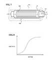
- FIG. 7is a schematic view of a friction control device in a rotary application
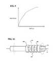
- FIG. 8is a graphical representation of a frictional force level with respect to an actuation signal provided to the friction control device
- FIG. 9is a graphical representation of a relative motion control with respect to the actuation signal provided to the friction control device
- FIG. 10is a schematic view of a slot orientation in the friction control device for a rotary application
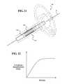
- FIG. 11is a schematic view of a steering wheel system application controlled by the friction control device
- FIG. 12is a graphical representation of a selective steering wheel resistance feel provided by the friction control device.
- FIG. 13is a schematic view of a suspension system application controlled by the friction control device.
- FIG. 1schematically illustrates a friction control device 20 .
- the friction control device 20generally includes an active material layer 22 and a slotted shield 24 .
- Suitable active materials for the active material layer 22include, without limitation, shape memory alloys (SMA), ferromagnetic shape memory alloys (MSMA), electroactive polymers (EAP), piezoelectric materials, magnetorheological (MR) elastomers, electrorheological (ER) elastomers, electrostrictive materials, magnetostrictive materials, and the like.
- the activation signal for the active material layer 22can take the form of, without limitation, an electric current, an electric field (voltage), a temperature change, a magnetic field, a mechanical loading or stressing (such as stress induced superelasticity in SMA), a chemistry or pH change, and the like.
- the active material layer 22When actuated, the active material layer 22 may expand to, in one example, twice its thickness, but a variable thickness is readily achieved through control of the actuation signal such as through a variable current. Alternatively, the active material layer 22 is selectively contracted in response to the actuation signal.
- the slotted shield 24includes a multiple of slots 26 arranged through which the active material layer 22 extends when in the actuated condition ( FIG. 2 ). It should be appreciated that although the multiple of slots 26 in the disclosed non-limiting embodiment are arranged in parallel, other relationships will benefit herefrom.
- the multiple of slots 26operate to stabilize and focus the active material layer 22 when actuated. That is, the active material layer 22 selectively extends at least partially through the multiple of slots 26 when in an actuated condition ( FIG. 2 ) as compared to a deactivated condition ( FIG. 3 ) in which the active material layer 22 does not extend—or extends to a lesser extent—through the multiple of slots 26 as compared to the actuated condition.
- the friction control device 20thereby controls a frictional interface 30 to change a frictional force between a first component 32 and a second component 34 .
- the multiple of slots 26may include slots of various widths W and/or lengths L 26 - 1 , 26 - 2 , 26 - 3 and combinations thereof ( FIG. 4 ). That is, at least one of the multiple of slots 26 may includes a first slot having a width W and/or a length L different than a second of the multiple of slots 26 . It should be appreciated that “slots” as defined herein includes various extended apertures of various configurations and geometries. Further, the multiple of slots 26 may be arranged in various patterns other than a rectilinear pattern such as, for example, a triangle ( FIG. 5 ), a chevron ( FIG. 6 ) or other shapes and/or patterns may be provided to further tailor the frictional force provided by the frictional interface 30 .
- a friction control device 20 Ais located at a rotational frictional interface 40 between a first component 32 A and a second component 34 A.
- the first component 32 Arotates relative to the second component 34 A about an axis A.
- Selective actuation of the friction control device 20 Aoperates to control the frictional force between the components 32 A, 34 A with respect to the activation signal ( FIG. 8 ).
- an increased voltageresults in an increased frictional force at the rotational frictional interference.
- particular slot shapes and arrangementsmay be selected to further tailor the frictional force.
- the first component 32 Arotates relative to the second component 34 A about the axis A and the slots 26 A are arranged transverse to the direction of rotation (illustrated schematically by arrow R). That is, the slots 26 A are arranged generally parallel to the axis A.
- the first component 32 Bslides relative to the second component 34 B along an axis B and the slots 26 B of the friction control device 20 B are transverse to the axis B ( FIG. 10 ).
- the friction control device 20 Amay be utilized in an example steering system 50 application to facilitate a desired steering resistance feel in response to the activation signal ( FIG. 12 ).
- the friction control device 20 Bmay be utilized in an example suspension system 60 application to facilitate a desired suspension effect such as hard, soft, etc., in response to the activation signal.
Landscapes
- Engineering & Computer Science (AREA)
- General Engineering & Computer Science (AREA)
- Mechanical Engineering (AREA)
- Physics & Mathematics (AREA)
- Electromagnetism (AREA)
- Vehicle Body Suspensions (AREA)
Abstract
Description
Claims (20)
Priority Applications (1)
| Application Number | Priority Date | Filing Date | Title |
|---|---|---|---|
| US14/041,144US9267563B2 (en) | 2013-09-30 | 2013-09-30 | Frictional control system |
Applications Claiming Priority (1)
| Application Number | Priority Date | Filing Date | Title |
|---|---|---|---|
| US14/041,144US9267563B2 (en) | 2013-09-30 | 2013-09-30 | Frictional control system |
Publications (2)
| Publication Number | Publication Date |
|---|---|
| US20150090544A1 US20150090544A1 (en) | 2015-04-02 |
| US9267563B2true US9267563B2 (en) | 2016-02-23 |
Family
ID=52739000
Family Applications (1)
| Application Number | Title | Priority Date | Filing Date |
|---|---|---|---|
| US14/041,144Expired - Fee RelatedUS9267563B2 (en) | 2013-09-30 | 2013-09-30 | Frictional control system |
Country Status (1)
| Country | Link |
|---|---|
| US (1) | US9267563B2 (en) |
Families Citing this family (1)
| Publication number | Priority date | Publication date | Assignee | Title |
|---|---|---|---|---|
| WO2017220352A1 (en) | 2016-06-20 | 2017-12-28 | Koninklijke Philips N.V. | Friction control device and method |
Citations (13)
| Publication number | Priority date | Publication date | Assignee | Title |
|---|---|---|---|---|
| US6193303B1 (en)* | 1998-04-03 | 2001-02-27 | Honda Giken Kogyo Kabushiki Kaisha | Control device for controlling rigidity and deformation of car body |
| US6378671B1 (en)* | 2000-03-29 | 2002-04-30 | Lord Corporation | Magnetically actuated motion control device |
| US6910714B2 (en)* | 2003-04-02 | 2005-06-28 | General Motors Corporation | Energy absorbing assembly and methods for operating the same |
| US20060225973A1 (en)* | 2005-03-30 | 2006-10-12 | Dimig Steven J | Residual magnetic devices and methods |
| US20070092685A1 (en)* | 2003-07-01 | 2007-04-26 | Honda Motor Co., Ltd. | Skeleton structural member for transportation equipment and manufacturing method for the skeleton structural member |
| US7401845B2 (en)* | 2005-11-04 | 2008-07-22 | Gm Global Technology Operations, Inc. | Active material based tunable property automotive brackets |
| US20080197674A1 (en)* | 2004-06-09 | 2008-08-21 | General Motors Corporation | Hood assembly utilizing active materials based mechanisms |
| US20090047197A1 (en) | 2007-08-16 | 2009-02-19 | Gm Global Technology Operations, Inc. | Active material based bodies for varying surface texture and frictional force levels |
| US20090045042A1 (en) | 2007-08-16 | 2009-02-19 | Gm Global Technology Operations, Inc. | Active material based bodies for varying frictional force levels at the interface between two surfaces |
| US7669918B2 (en) | 2004-12-09 | 2010-03-02 | Gm Global Technology Operations, Inc. | Tunable vehicle structural members and methods for selectively changing the mechanical properties thereto |
| US7787646B2 (en) | 2003-09-03 | 2010-08-31 | Sri International | Surface deformation electroactive polymer transducers |
| US20100264693A1 (en)* | 2009-04-15 | 2010-10-21 | Toyota Motor Engineering & Manufacturing North America, Inc. | Prestressed Structural Members and Methods of Making Same |
| US8164232B2 (en)* | 2004-03-12 | 2012-04-24 | Sri International | Mechanical meta-materials |
- 2013
- 2013-09-30USUS14/041,144patent/US9267563B2/ennot_activeExpired - Fee Related
Patent Citations (14)
| Publication number | Priority date | Publication date | Assignee | Title |
|---|---|---|---|---|
| US6193303B1 (en)* | 1998-04-03 | 2001-02-27 | Honda Giken Kogyo Kabushiki Kaisha | Control device for controlling rigidity and deformation of car body |
| US6378671B1 (en)* | 2000-03-29 | 2002-04-30 | Lord Corporation | Magnetically actuated motion control device |
| US6910714B2 (en)* | 2003-04-02 | 2005-06-28 | General Motors Corporation | Energy absorbing assembly and methods for operating the same |
| US20070092685A1 (en)* | 2003-07-01 | 2007-04-26 | Honda Motor Co., Ltd. | Skeleton structural member for transportation equipment and manufacturing method for the skeleton structural member |
| US7787646B2 (en) | 2003-09-03 | 2010-08-31 | Sri International | Surface deformation electroactive polymer transducers |
| US8164232B2 (en)* | 2004-03-12 | 2012-04-24 | Sri International | Mechanical meta-materials |
| US20080197674A1 (en)* | 2004-06-09 | 2008-08-21 | General Motors Corporation | Hood assembly utilizing active materials based mechanisms |
| US7669918B2 (en) | 2004-12-09 | 2010-03-02 | Gm Global Technology Operations, Inc. | Tunable vehicle structural members and methods for selectively changing the mechanical properties thereto |
| US20060225973A1 (en)* | 2005-03-30 | 2006-10-12 | Dimig Steven J | Residual magnetic devices and methods |
| US7401845B2 (en)* | 2005-11-04 | 2008-07-22 | Gm Global Technology Operations, Inc. | Active material based tunable property automotive brackets |
| US20090045042A1 (en) | 2007-08-16 | 2009-02-19 | Gm Global Technology Operations, Inc. | Active material based bodies for varying frictional force levels at the interface between two surfaces |
| US20090047197A1 (en) | 2007-08-16 | 2009-02-19 | Gm Global Technology Operations, Inc. | Active material based bodies for varying surface texture and frictional force levels |
| US20100264693A1 (en)* | 2009-04-15 | 2010-10-21 | Toyota Motor Engineering & Manufacturing North America, Inc. | Prestressed Structural Members and Methods of Making Same |
| US8167363B2 (en)* | 2009-04-15 | 2012-05-01 | Toyota Motor Engineering & Manufacturing North America, Inc. | Prestressed structural members and methods of making same |
Also Published As
| Publication number | Publication date |
|---|---|
| US20150090544A1 (en) | 2015-04-02 |
Similar Documents
| Publication | Publication Date | Title |
|---|---|---|
| CN106945716B (en) | The method of feedback is provided in torque feedback system, vehicle and vehicle with steering column | |
| EP3124346B1 (en) | Electric brake device and electric brake device system | |
| US9381934B2 (en) | Steering system | |
| CN109131555A (en) | For providing the vehicle and wheel steering system of touch feedback | |
| US9496105B2 (en) | System for dynamically adjustable detent | |
| KR20170134299A (en) | Vehicular control apparatus | |
| US20180328472A1 (en) | Ball screw drive | |
| US9267563B2 (en) | Frictional control system | |
| CN107368114B (en) | Active Vibration Control Device | |
| US9771986B2 (en) | Selectable one-way clutch | |
| EP3371488B1 (en) | A shift actuator assembly for a vehicle transmission | |
| JP2015525164A (en) | Accelerator pedal unit for vehicles | |
| WO2015094622A1 (en) | Turbomachine blade clearance control system | |
| JP2014510509A5 (en) | ||
| US8919218B2 (en) | Transmission system for shift by wire | |
| JP6283549B2 (en) | Steering device | |
| CN106132823B (en) | Rotation blocking device with simplified structure and actuator comprising such a device | |
| CN111038574A (en) | Steering device of steer-by-wire system | |
| JP4124118B2 (en) | Steering system deployment actuator | |
| KR101865966B1 (en) | Safety device of vehicle | |
| JP4193576B2 (en) | Vehicle steering system | |
| US20200298902A1 (en) | Method for operating a steering system | |
| CN104299823B (en) | Device for switching control electronics | |
| US10442317B2 (en) | Virtual limit correction device of power seat for vehicle, and correction method therefor | |
| CN106460970A (en) | Off-excitation operating brakes and electric motors with off-excitation operating brakes |
Legal Events
| Date | Code | Title | Description |
|---|---|---|---|
| AS | Assignment | Owner name:TOYOTA MOTOR ENGINEERING & MANUFACTURING NORTH AME Free format text:ASSIGNMENT OF ASSIGNORS INTEREST;ASSIGNOR:GANDHI, UMESH N.;REEL/FRAME:031309/0641 Effective date:20130925 | |
| ZAAA | Notice of allowance and fees due | Free format text:ORIGINAL CODE: NOA | |
| ZAAB | Notice of allowance mailed | Free format text:ORIGINAL CODE: MN/=. | |
| STCF | Information on status: patent grant | Free format text:PATENTED CASE | |
| AS | Assignment | Owner name:TOYOTA JIDOSHA KABUSHIKI KAISHA, JAPAN Free format text:ASSIGNMENT OF ASSIGNORS INTEREST;ASSIGNOR:TOYOTA MOTOR ENGINEERING & MANUFACTURING NORTH AMERICA, INC.;REEL/FRAME:037868/0951 Effective date:20160224 | |
| MAFP | Maintenance fee payment | Free format text:PAYMENT OF MAINTENANCE FEE, 4TH YEAR, LARGE ENTITY (ORIGINAL EVENT CODE: M1551); ENTITY STATUS OF PATENT OWNER: LARGE ENTITY Year of fee payment:4 | |
| FEPP | Fee payment procedure | Free format text:MAINTENANCE FEE REMINDER MAILED (ORIGINAL EVENT CODE: REM.); ENTITY STATUS OF PATENT OWNER: LARGE ENTITY | |
| LAPS | Lapse for failure to pay maintenance fees | Free format text:PATENT EXPIRED FOR FAILURE TO PAY MAINTENANCE FEES (ORIGINAL EVENT CODE: EXP.); ENTITY STATUS OF PATENT OWNER: LARGE ENTITY | |
| STCH | Information on status: patent discontinuation | Free format text:PATENT EXPIRED DUE TO NONPAYMENT OF MAINTENANCE FEES UNDER 37 CFR 1.362 | |
| FP | Lapsed due to failure to pay maintenance fee | Effective date:20240223 |