US9266164B2 - Extreme offset nose assembly with secondary bearing - Google Patents
Extreme offset nose assembly with secondary bearingDownload PDFInfo
- Publication number
- US9266164B2 US9266164B2US14/208,705US201414208705AUS9266164B2US 9266164 B2US9266164 B2US 9266164B2US 201414208705 AUS201414208705 AUS 201414208705AUS 9266164 B2US9266164 B2US 9266164B2
- Authority
- US
- United States
- Prior art keywords
- collet
- nose assembly
- anvil
- bearing
- drawbar
- Prior art date
- Legal status (The legal status is an assumption and is not a legal conclusion. Google has not performed a legal analysis and makes no representation as to the accuracy of the status listed.)
- Active, expires
Links
Images


Classifications
- B—PERFORMING OPERATIONS; TRANSPORTING
- B21—MECHANICAL METAL-WORKING WITHOUT ESSENTIALLY REMOVING MATERIAL; PUNCHING METAL
- B21J—FORGING; HAMMERING; PRESSING METAL; RIVETING; FORGE FURNACES
- B21J15/00—Riveting
- B21J15/02—Riveting procedures
- B21J15/022—Setting rivets by means of swaged-on locking collars, e.g. lockbolts
- Y—GENERAL TAGGING OF NEW TECHNOLOGICAL DEVELOPMENTS; GENERAL TAGGING OF CROSS-SECTIONAL TECHNOLOGIES SPANNING OVER SEVERAL SECTIONS OF THE IPC; TECHNICAL SUBJECTS COVERED BY FORMER USPC CROSS-REFERENCE ART COLLECTIONS [XRACs] AND DIGESTS
- Y10—TECHNICAL SUBJECTS COVERED BY FORMER USPC
- Y10T—TECHNICAL SUBJECTS COVERED BY FORMER US CLASSIFICATION
- Y10T29/00—Metal working
- Y10T29/53—Means to assemble or disassemble
- Y10T29/53796—Puller or pusher means, contained force multiplying operator
Definitions
- the present inventionrelates to fastener installation tools, and, more particularly, to fastener installation tools having extreme offset nose assemblies.
- a fastener installation tool having an extreme offset nose assemblyis utilized when the fastener centerline is offset at a relatively large distance from the tool. There is a need to limit the deflection of the nose assembly when installing the fastener.
- a nose assembly for a fastener installation toolincluding an anvil; a collet disposed within the anvil, the collet including jaws; a drawbar supported by the anvil and the collet, the drawbar having a first end, a second end opposite the first end, and a primary bearing located at the first end; and a secondary bearing positioned within the collet and located intermediate the primary bearing of the drawbar and the jaws of the collet.
- the secondary bearingis located proximate to a fastener centerline defined by a longitudinal axis of the jaws.
- the secondary bearingis offset from the fastener centerline by a first distance and is offset from a pulling tool centerline axis defined by a longitudinal axis of the drawbar by a second distance. In an embodiment, the first distance is less than the second distance.
- the nose assemblyis adapted to be activated in a pull position, such that the primary bearing remains engaged with the anvil during a loaded stroke and limits anvil deflection relative to the fastener center line and supports an installation load, while the secondary bearing remains engaged with the collet during the loaded stroke and limits deflection of the collet relative to the fastener center line.
- the nose assemblyis adapted to be activated in a return position, such that the primary bearing remains engaged with the anvil during a return stroke, while the secondary bearing remains engaged with the collet during the return stroke.
- the secondary bearingis attached to the collet and engaged with the anvil. In an embodiment, the secondary bearing is fastened threadedly to the collet. In an embodiment, the secondary bearing is retained to the collet by a retaining ring. In an embodiment, the secondary bearing is retained to the collet by a retainer clip.
- the colletincludes an aperture having internal threads and the drawbar includes external threads that engage threadedly the internal threads of the aperture of the collet.
- the drawbarincludes a rear bearing located intermediate the first and second ends of the drawbar.
- the anvilis a swaging anvil. In an embodiment, the anvil is a stand-off anvil. In an embodiment, the drawbar includes a stop located at the second end thereof. In an embodiment, the nose assembly includes a deflector in communication with the collet.
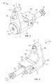
- FIG. 1is a front perspective view of a nose assembly for a fastener installation tool constructed in accordance with an embodiment
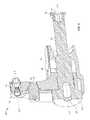
- FIG. 2is a rear perspective view of the nose assembly shown in FIG. 1 ;
- FIG. 3is a front elevational view of the nose assembly shown in FIG. 1 ;
- FIG. 4is a cross-sectional view, taken along section lines A-A and looking in the direction of the arrows, of the nose assembly shown in FIG. 3 ;
- FIG. 5is a front perspective view of the nose assembly shown in FIG. 1 attached to an installation tool;
- FIG. 6is a partial cross-sectional view of the nose assembly shown in FIG. 5 ;
- FIG. 7is a cross-sectional view of the nose assembly shown in FIG. 1 , the nose assembly activated in a pull position;
- FIG. 8is a cross-sectional view of the nose assembly shown in FIG. 7 , but with the nose assembly activated in a return position.
- a nose assembly 10 for a fastener installation toolincludes a first end 3 , a second end 5 opposite the first end 3 , a top end 7 , and a bottom end 9 opposite the top end 7 .
- the nose assembly 10includes an anvil 12 , a collet 14 disposed within the anvil 12 and having unitized jaws 16 , and an associated deflector 18 in communication with the collet 14 (see FIG. 4 ).
- the collet 14includes an aperture 15 having internal threads 17 (see FIG. 4 ).
- the anvil 12is a swaging anvil.
- the anvil 12is a stand-off anvil in the case of a pull-in application.
- the collet 14is disposed slidably within the anvil 12 .
- the nose assembly 10includes a drawbar 20 having a primary bearing 22 at a first end thereof and a stop 24 at second end opposite the first end.
- the primary bearing 22 of the drawbar 20includes an internal hexagonal recess 21 located at the first end of the drawbar 20 that is sized and shaped to receive a hexagonal key (not shown in the Figures).
- the stop 24 of the drawbar 20includes an internal hexagonal recess 23 that is sized and shaped to receive a hexagonal key.
- a portion of the drawbar 20 located proximate to the primary bearing 22contains external threads 25 .
- the external threads 25engage threadedly the internal threads 17 of the collet 14 .
- the drawbar 20is shrouded partially by a back guard 26 and a wrap-around guard 28 .
- the drawbar 20is supported by the anvil 12 and the collet 14 and extends through a plurality of apertures and bores formed within the anvil 12 and the collet 14 , such apertures being shown in FIG. 4 but not described herein for the sake of brevity.
- the drawbar 20includes a rear bearing 27 positioned intermediate the primary bearing 22 and the stop 24 .
- the anvil 12 , the collet 14 and the drawbar 20have a structure and function similar to the corresponding components disclosed in the '534 patent and the '245 patent, with certain differences as noted below.
- the nose assembly 10includes a secondary bearing 30 located proximate to a fastener centerline X-X defined by a longitudinal axis of the jaws 16 , and is located intermediate the fastener centerline X-X and the primary bearing 22 (see FIG. 4 ).
- the secondary bearing 30is offset from the fastener centerline X-X by a first distance D1 and is offset from a pulling tool centerline axis Y-Y defined by a longitudinal axis of the drawbar 20 by a second distance D2 (see FIG. 4 ).
- the secondary bearing 30is fastened threadedly to the collet 14 by a threaded portion 32 .
- the secondary bearing 30is fastened to the collet 14 by any other type of connection that will support frictional forces along the pulling tool centerline axis Y-Y.
- the secondary bearing 30is retained to the collet 14 by a retainer ring or a retainer clip (not shown in the Figures).
- the secondary bearing 30has a close mating running fit with the anvil 12 which has a bore that receives and is in close communication with an outside diameter of the secondary bearing 30 .
- the foregoing arrangementlimits the relative deflection between the anvil 12 and the collet 14 .
- the secondary bearing 30supports the bending moment imposed when installing a fastener.
- the stresses in the components of the nose assembly 10are reduced due to the dual bearing approach, i.e., the primary bearing 22 bearing on the anvil 12 and the secondary bearing 30 bearing on the work surface (not shown).
- the nose assembly 10is attached to a fastener installation tool 50 .
- the drawbar 20is installed in the collet 14 and backed-off one turn. Then, the entire nose assembly 10 is rotated onto the tool 50 until it is in a home position. Then, it is locked in with a locking disk on the tool 50 (not shown).
- the collet 14is adjusted fully forward by turning the drawbar 20 via a key in the hexagonal recess 21 . It is then locked in placed by tightening the stop 22 from the back of the tool 50 .
- a fastener 52is installed in the collet 14 .
- the fastenerhas a pin member 54 and swage collar 56 .
- the nose assembly 10engages the fastener 52 for securing a workpiece W.
- FIG. 7shows the nose assembly 10 activated in a pull position.
- the primary bearing 22in line with pulling tool centerline Y-Y
- the secondary bearing 30offset from pulling tool centerline Y-Y
- the maximum deflection of the collet 14 relative to the fastener center line X-Xis approximately 0.005′′.
- FIG. 8shows the nose assembly 10 in a return position.
- the primary bearing 22in line with pulling tool centerline Y-Y
- the secondary bearing 30offset from pulling tool centerline Y-Y
- the collet 14remains engaged with the collet 14 during the return stroke.
- a fasteneris installed in the jaws 16 of the collet 14 (i.e., oriented along the fastener centerline X-X).
- the loaded strokeis applied by the tool to the drawbar 20 until the primary bearing 22 bears on the anvil 12 and the secondary bearing 30 bears on the work surface and the fastener is fully installed.
- the return strokeis applied by the tool to the drawbar 20 until the primary bearing 22 and the secondary bearing 30 are positioned in the returned position. During the return stroke, the direction of flight of the pin tail that is broken off the shank of the fastener is redirected by the deflector 18 safely and with reduced energy.
Landscapes
- Engineering & Computer Science (AREA)
- Mechanical Engineering (AREA)
- Insertion Pins And Rivets (AREA)
- Forging (AREA)
- Mounting Of Bearings Or Others (AREA)
- Portable Nailing Machines And Staplers (AREA)
- Surgical Instruments (AREA)
- Gripping On Spindles (AREA)
Abstract
Description
Claims (15)
Priority Applications (1)
| Application Number | Priority Date | Filing Date | Title |
|---|---|---|---|
| US14/208,705US9266164B2 (en) | 2013-03-15 | 2014-03-13 | Extreme offset nose assembly with secondary bearing |
Applications Claiming Priority (2)
| Application Number | Priority Date | Filing Date | Title |
|---|---|---|---|
| US201361791024P | 2013-03-15 | 2013-03-15 | |
| US14/208,705US9266164B2 (en) | 2013-03-15 | 2014-03-13 | Extreme offset nose assembly with secondary bearing |
Publications (2)
| Publication Number | Publication Date |
|---|---|
| US20140259585A1 US20140259585A1 (en) | 2014-09-18 |
| US9266164B2true US9266164B2 (en) | 2016-02-23 |
Family
ID=50631017
Family Applications (1)
| Application Number | Title | Priority Date | Filing Date |
|---|---|---|---|
| US14/208,705Active2034-05-01US9266164B2 (en) | 2013-03-15 | 2014-03-13 | Extreme offset nose assembly with secondary bearing |
Country Status (6)
| Country | Link |
|---|---|
| US (1) | US9266164B2 (en) |
| EP (1) | EP2969299B8 (en) |
| JP (1) | JP6133487B2 (en) |
| CN (2) | CN104044111A (en) |
| ES (1) | ES2813773T3 (en) |
| WO (1) | WO2014151471A2 (en) |
Cited By (2)
| Publication number | Priority date | Publication date | Assignee | Title |
|---|---|---|---|---|
| US20180126526A1 (en)* | 2016-11-09 | 2018-05-10 | Aerofit, Llc | Axial swage tool |
| US11384871B2 (en)* | 2015-05-05 | 2022-07-12 | Aerofit, Llc | Axial swage tool |
Families Citing this family (1)
| Publication number | Priority date | Publication date | Assignee | Title |
|---|---|---|---|---|
| EP2969299B8 (en)* | 2013-03-15 | 2020-08-12 | Howmet Aerospace Inc. | Extreme offset nose assembly with secondary bearing |
Citations (15)
| Publication number | Priority date | Publication date | Assignee | Title |
|---|---|---|---|---|
| US3713321A (en) | 1971-07-22 | 1973-01-30 | Parker Mfg Co | Rivet gun |
| US4615206A (en) | 1985-04-01 | 1986-10-07 | Huck Manufacturing Company | Offset tool and cartridge nose assembly |
| US4796455A (en)* | 1987-03-24 | 1989-01-10 | Huck Manufacturing Company | Compact offset nose assembly for setting fasteners |
| US4813261A (en)* | 1988-03-02 | 1989-03-21 | Huck Manufacturing Company | Rotatable offset nose assembly for setting fasteners |
| US4879875A (en)* | 1988-03-22 | 1989-11-14 | The Boeing Company | Fastener driving tool |
| US4896522A (en)* | 1989-03-21 | 1990-01-30 | Huck Manufacturing Company | Rotatable coupling for fastener installation tool |
| US5371933A (en) | 1994-04-05 | 1994-12-13 | Gbp Corporation | Fastener setting tool with offset nose assembly |
| US6516510B1 (en)* | 2000-09-13 | 2003-02-11 | Huck International, Inc. | Installation tool for installing swage type threaded fasteners |
| US6662420B1 (en)* | 2002-09-04 | 2003-12-16 | Huck International, Inc. | Hydraulic installation tool |
| US6739170B1 (en) | 2003-03-17 | 2004-05-25 | Huck International, Inc. | Offset nose assembly with improved deflector and guard assemblies |
| US6854178B2 (en)* | 2002-04-02 | 2005-02-15 | The Boeing Company | Through-the-drill plate fastener installation tool |
| US7458245B1 (en) | 2008-04-08 | 2008-12-02 | Huck International, Inc. | Extreme offset nose assembly |
| US7665342B2 (en)* | 2008-06-02 | 2010-02-23 | Sps Technologies, Llc | Compact universal offset pulling head for fasteners |
| CN102145481A (en) | 2010-02-01 | 2011-08-10 | 美铝公司 | Nose assembly for fastener installation tool |
| CN203779452U (en) | 2013-03-15 | 2014-08-20 | 美铝公司 | Head part component for fastener mounting tool |
Family Cites Families (1)
| Publication number | Priority date | Publication date | Assignee | Title |
|---|---|---|---|---|
| US5208959A (en)* | 1991-05-10 | 1993-05-11 | Huck Patents, Inc. | Offset nose assembly with pin releasing assembly for fastener installation tools |
- 2014
- 2014-03-13EPEP14721073.6Apatent/EP2969299B8/enactiveActive
- 2014-03-13USUS14/208,705patent/US9266164B2/enactiveActive
- 2014-03-13JPJP2016501971Apatent/JP6133487B2/enactiveActive
- 2014-03-13WOPCT/US2014/025808patent/WO2014151471A2/enactiveApplication Filing
- 2014-03-13ESES14721073Tpatent/ES2813773T3/enactiveActive
- 2014-03-17CNCN201410098511.1Apatent/CN104044111A/enactivePending
- 2014-03-17CNCN201420119851.3Upatent/CN203779452U/ennot_activeExpired - Lifetime
Patent Citations (18)
| Publication number | Priority date | Publication date | Assignee | Title |
|---|---|---|---|---|
| US3713321A (en) | 1971-07-22 | 1973-01-30 | Parker Mfg Co | Rivet gun |
| US4615206A (en) | 1985-04-01 | 1986-10-07 | Huck Manufacturing Company | Offset tool and cartridge nose assembly |
| WO1986005723A1 (en) | 1985-04-01 | 1986-10-09 | Huck Manufacturing Company | Offset tool and cartridge nose assembly |
| CN86102208A (en) | 1985-04-01 | 1987-02-18 | 赫克制造公司 | Biasing head instrument and integrated head assembly |
| US4796455A (en)* | 1987-03-24 | 1989-01-10 | Huck Manufacturing Company | Compact offset nose assembly for setting fasteners |
| US4813261A (en)* | 1988-03-02 | 1989-03-21 | Huck Manufacturing Company | Rotatable offset nose assembly for setting fasteners |
| US4879875A (en)* | 1988-03-22 | 1989-11-14 | The Boeing Company | Fastener driving tool |
| US4896522A (en)* | 1989-03-21 | 1990-01-30 | Huck Manufacturing Company | Rotatable coupling for fastener installation tool |
| US5371933A (en) | 1994-04-05 | 1994-12-13 | Gbp Corporation | Fastener setting tool with offset nose assembly |
| US6516510B1 (en)* | 2000-09-13 | 2003-02-11 | Huck International, Inc. | Installation tool for installing swage type threaded fasteners |
| US6854178B2 (en)* | 2002-04-02 | 2005-02-15 | The Boeing Company | Through-the-drill plate fastener installation tool |
| US6662420B1 (en)* | 2002-09-04 | 2003-12-16 | Huck International, Inc. | Hydraulic installation tool |
| US6739170B1 (en) | 2003-03-17 | 2004-05-25 | Huck International, Inc. | Offset nose assembly with improved deflector and guard assemblies |
| US7458245B1 (en) | 2008-04-08 | 2008-12-02 | Huck International, Inc. | Extreme offset nose assembly |
| US7631534B2 (en) | 2008-04-08 | 2009-12-15 | Buck International, Inc. | Extreme offset nose assembly |
| US7665342B2 (en)* | 2008-06-02 | 2010-02-23 | Sps Technologies, Llc | Compact universal offset pulling head for fasteners |
| CN102145481A (en) | 2010-02-01 | 2011-08-10 | 美铝公司 | Nose assembly for fastener installation tool |
| CN203779452U (en) | 2013-03-15 | 2014-08-20 | 美铝公司 | Head part component for fastener mounting tool |
Non-Patent Citations (1)
| Title |
|---|
| International Search Report and Written Opinion dated Sep. 18, 2014, issued by the European Patent Office in International (PCT) Application No. PCT/US2014/025808 (10 pages). |
Cited By (3)
| Publication number | Priority date | Publication date | Assignee | Title |
|---|---|---|---|---|
| US11384871B2 (en)* | 2015-05-05 | 2022-07-12 | Aerofit, Llc | Axial swage tool |
| US20180126526A1 (en)* | 2016-11-09 | 2018-05-10 | Aerofit, Llc | Axial swage tool |
| US10828757B2 (en)* | 2016-11-09 | 2020-11-10 | Aerofit, Llc | Axial swage tool |
Also Published As
| Publication number | Publication date |
|---|---|
| EP2969299B1 (en) | 2020-07-08 |
| JP2016511163A (en) | 2016-04-14 |
| ES2813773T3 (en) | 2021-03-24 |
| EP2969299A2 (en) | 2016-01-20 |
| CN104044111A (en) | 2014-09-17 |
| WO2014151471A3 (en) | 2014-11-13 |
| WO2014151471A2 (en) | 2014-09-25 |
| US20140259585A1 (en) | 2014-09-18 |
| EP2969299B8 (en) | 2020-08-12 |
| JP6133487B2 (en) | 2017-05-24 |
| CN203779452U (en) | 2014-08-20 |
Similar Documents
| Publication | Publication Date | Title |
|---|---|---|
| US8777533B2 (en) | Blind fastener | |
| EP2336580B1 (en) | Fastener system | |
| EP2511540B1 (en) | Blind rivet and fastening method thereof | |
| US8979453B2 (en) | Blind fastener | |
| US8246281B2 (en) | Captive fasteners with multiple retaining functionality | |
| US9488213B2 (en) | Fastener and fastener installation tool | |
| US9829026B2 (en) | Anchor bolt | |
| US9266164B2 (en) | Extreme offset nose assembly with secondary bearing | |
| TW201418589A (en) | Lockbolt | |
| CN105889255A (en) | Blind rivet with rubber sealing bush | |
| US8029220B2 (en) | Blind rivet assembly | |
| CA2769951C (en) | Fastening arrangement | |
| JP2012107663A (en) | Blind rivet and fastening method thereof | |
| GB2421554A (en) | Blind fastener device | |
| CN104454871A (en) | Rivet | |
| US9550228B2 (en) | Dual piston close clearance fastening tool | |
| EP2852767B1 (en) | Swage indicating collar | |
| US20080060192A1 (en) | High performance nosepiece for blind bolt installation | |
| US12281666B2 (en) | Circular pin clip with fixed spreader |
Legal Events
| Date | Code | Title | Description |
|---|---|---|---|
| AS | Assignment | Owner name:ALCOA INC., PENNSYLVANIA Free format text:ASSIGNMENT OF ASSIGNORS INTEREST;ASSIGNORS:WILCOX, ROBERT;GOUGOUTRIS, NICHOLAS;REEL/FRAME:032745/0697 Effective date:20130430 | |
| STCF | Information on status: patent grant | Free format text:PATENTED CASE | |
| AS | Assignment | Owner name:ARCONIC INC., PENNSYLVANIA Free format text:CHANGE OF NAME;ASSIGNOR:ALCOA INC.;REEL/FRAME:040599/0309 Effective date:20161031 | |
| MAFP | Maintenance fee payment | Free format text:PAYMENT OF MAINTENANCE FEE, 4TH YEAR, LARGE ENTITY (ORIGINAL EVENT CODE: M1551); ENTITY STATUS OF PATENT OWNER: LARGE ENTITY Year of fee payment:4 | |
| AS | Assignment | Owner name:ARCONIC INC., PENNSYLVANIA Free format text:MERGER;ASSIGNOR:ARCONIC INC.;REEL/FRAME:054698/0521 Effective date:20171229 Owner name:ARCONIC INC., PENNSYLVANIA Free format text:MERGER;ASSIGNOR:ARCONIC INC.;REEL/FRAME:054698/0580 Effective date:20171229 | |
| AS | Assignment | Owner name:HOWMET AEROSPACE INC., PENNSYLVANIA Free format text:CHANGE OF NAME;ASSIGNOR:ARCONIC INC.;REEL/FRAME:054821/0882 Effective date:20200331 | |
| MAFP | Maintenance fee payment | Free format text:PAYMENT OF MAINTENANCE FEE, 8TH YEAR, LARGE ENTITY (ORIGINAL EVENT CODE: M1552); ENTITY STATUS OF PATENT OWNER: LARGE ENTITY Year of fee payment:8 |