US9265677B2 - Hospital chair beds with stowable stand-assist supports - Google Patents
Hospital chair beds with stowable stand-assist supportsDownload PDFInfo
- Publication number
- US9265677B2 US9265677B2US13/516,271US201013516271AUS9265677B2US 9265677 B2US9265677 B2US 9265677B2US 201013516271 AUS201013516271 AUS 201013516271AUS 9265677 B2US9265677 B2US 9265677B2
- Authority
- US
- United States
- Prior art keywords
- stand
- panel
- support surface
- bed
- patient support
- Prior art date
- Legal status (The legal status is an assumption and is not a legal conclusion. Google has not performed a legal analysis and makes no representation as to the accuracy of the status listed.)
- Expired - Fee Related, expires
Links
Images


Classifications
- A—HUMAN NECESSITIES
- A61—MEDICAL OR VETERINARY SCIENCE; HYGIENE
- A61G—TRANSPORT, PERSONAL CONVEYANCES, OR ACCOMMODATION SPECIALLY ADAPTED FOR PATIENTS OR DISABLED PERSONS; OPERATING TABLES OR CHAIRS; CHAIRS FOR DENTISTRY; FUNERAL DEVICES
- A61G7/00—Beds specially adapted for nursing; Devices for lifting patients or disabled persons
- A61G7/10—Devices for lifting patients or disabled persons, e.g. special adaptations of hoists thereto
- A61G7/16—Devices for lifting patients or disabled persons, e.g. special adaptations of hoists thereto converting a lying surface into a chair
- A—HUMAN NECESSITIES
- A61—MEDICAL OR VETERINARY SCIENCE; HYGIENE
- A61G—TRANSPORT, PERSONAL CONVEYANCES, OR ACCOMMODATION SPECIALLY ADAPTED FOR PATIENTS OR DISABLED PERSONS; OPERATING TABLES OR CHAIRS; CHAIRS FOR DENTISTRY; FUNERAL DEVICES
- A61G7/00—Beds specially adapted for nursing; Devices for lifting patients or disabled persons
- A61G7/05—Parts, details or accessories of beds
- A61G7/0507—Side-rails
- A61G7/0512—Side-rails characterised by customised length
- A61G7/0513—Side-rails characterised by customised length covering particular sections of the bed, e.g. one or more partial side-rail sections along the bed
- A61G7/0514—Side-rails characterised by customised length covering particular sections of the bed, e.g. one or more partial side-rail sections along the bed mounted to individual mattress supporting frame sections
- A—HUMAN NECESSITIES
- A61—MEDICAL OR VETERINARY SCIENCE; HYGIENE
- A61G—TRANSPORT, PERSONAL CONVEYANCES, OR ACCOMMODATION SPECIALLY ADAPTED FOR PATIENTS OR DISABLED PERSONS; OPERATING TABLES OR CHAIRS; CHAIRS FOR DENTISTRY; FUNERAL DEVICES
- A61G7/00—Beds specially adapted for nursing; Devices for lifting patients or disabled persons
- A61G7/05—Parts, details or accessories of beds
- A61G7/053—Aids for getting into, or out of, bed, e.g. steps, chairs, cane-like supports
- A61G2007/0514—
- A—HUMAN NECESSITIES
- A61—MEDICAL OR VETERINARY SCIENCE; HYGIENE
- A61G—TRANSPORT, PERSONAL CONVEYANCES, OR ACCOMMODATION SPECIALLY ADAPTED FOR PATIENTS OR DISABLED PERSONS; OPERATING TABLES OR CHAIRS; CHAIRS FOR DENTISTRY; FUNERAL DEVICES
- A61G2200/00—Information related to the kind of patient or his position
- A61G2200/30—Specific positions of the patient
- A61G2200/32—Specific positions of the patient lying
- A—HUMAN NECESSITIES
- A61—MEDICAL OR VETERINARY SCIENCE; HYGIENE
- A61G—TRANSPORT, PERSONAL CONVEYANCES, OR ACCOMMODATION SPECIALLY ADAPTED FOR PATIENTS OR DISABLED PERSONS; OPERATING TABLES OR CHAIRS; CHAIRS FOR DENTISTRY; FUNERAL DEVICES
- A61G2200/00—Information related to the kind of patient or his position
- A61G2200/30—Specific positions of the patient
- A61G2200/34—Specific positions of the patient sitting
- A—HUMAN NECESSITIES
- A61—MEDICAL OR VETERINARY SCIENCE; HYGIENE
- A61G—TRANSPORT, PERSONAL CONVEYANCES, OR ACCOMMODATION SPECIALLY ADAPTED FOR PATIENTS OR DISABLED PERSONS; OPERATING TABLES OR CHAIRS; CHAIRS FOR DENTISTRY; FUNERAL DEVICES
- A61G2200/00—Information related to the kind of patient or his position
- A61G2200/30—Specific positions of the patient
- A61G2200/36—Specific positions of the patient standing
- A—HUMAN NECESSITIES
- A61—MEDICAL OR VETERINARY SCIENCE; HYGIENE
- A61G—TRANSPORT, PERSONAL CONVEYANCES, OR ACCOMMODATION SPECIALLY ADAPTED FOR PATIENTS OR DISABLED PERSONS; OPERATING TABLES OR CHAIRS; CHAIRS FOR DENTISTRY; FUNERAL DEVICES
- A61G7/00—Beds specially adapted for nursing; Devices for lifting patients or disabled persons
- A61G7/10—Devices for lifting patients or disabled persons, e.g. special adaptations of hoists thereto
- A61G7/1073—Parts, details or accessories
- A61G7/1076—Means for rotating around a vertical axis
Definitions
- the present inventionrelates generally to the field of hospital beds and, more specifically, to hospital beds that are convertible into a chair configuration.
- Conventional hospital bedsare configured to provide a sufficiently comfortable support surface for patients in a supine position.
- patientsmay be interested in sitting up in bed to be more comfortable, for example, in order to read or meet with visitors.
- hospital bedsthat can be converted into chair-like configurations have been developed.
- hospital bedsthat can assist patients in moving from a supine position to a sitting position for the purpose of achieving a standing or walking position from a side egress orientation have also been developed.
- Embodiments of the inventionare directed to hospital beds with on-board, stowable stand-assist supports.
- Embodiments of the inventionare directed to hospital beds.
- the bedsinclude: (a) a base frame comprising laterally spaced apart first and second long sides and longitudinally spaced apart top and bottom end portions; (b) a patient support surface, wherein the patient support surface comprises a back panel, a seat panel, and a leg panel configured to articulate relative to each other, and wherein the patient support surface is configured to translate from a bed configuration to a chair configuration; and (c) first and second spaced stand-assist supports, one residing on each side of the back panel, wherein when the back panel is upwardly oriented and the patient support surface is in the chair configuration, the stand-assist supports are configured to reside above and on opposing sides of the seat panel and extend outwardly from the back panel toward the leg panel in a substantially horizontal orientation.
- Additional embodiments of the inventionare directed to hospital beds that include: (a) a base frame comprising laterally spaced apart first and second long sides and longitudinally spaced apart top and bottom end portions; (b) a lifting mechanism secured to the base frame; (c) a rotating frame mounted on the lifting mechanism, wherein the rotating frame is configured to rotate about a vertical axis relative to the base frame; (d) a patient support surface pivotally secured to the rotating frame, wherein the patient support surface comprises a back panel, a seat panel, and a leg panel configured to articulate relative to each other, and wherein the patient support surface is configured to translate from a bed configuration to a side-egress chair configuration; and (e) first and second spaced stand-assist supports, one residing on each side of the back panel to be able to rotate with the back panel to the side-egress chair configuration, wherein when the patient support surface is in the side-egress chair configuration, the stand-assist supports are configured to reside above and on opposing sides of the seat panel and extend outwardly from
- Embodiments of the present inventionare directed to hospital beds that have a patient support surface including a back panel, a seat panel and a leg panel.
- the bedis configured to rotate to a side egress chair configuration.
- the bedis characterized in that the hospital bed includes a pair of stand-assist supports, one residing proximate each long side of the back panel that are pivotably attached to a respective portion of the back panel and rotate with the back panel to the side-egress chair configuration.
- the stand-assist supportsare configured to pivot outward from the back panel to reside above and on opposing sides of the seat panel.
- Yet other embodimentsare directed to methods of operating a hospital bed.
- the methodsinclude pivoting a pair of stand-assist supports from a respective stowed position proximate opposing sides of an outer perimeter of a back panel to an outwardly extending configuration above a seat panel of the patient support surface so that one support resides on one side of a seat panel and the other resides on the other side of the seat panel.
- the methodmay include converting the bed into a chair bed either an end egress or side egress chair bed.
- the methodsmay include (a) rotating an articulating patient support surface to a side egress position; and pivoting the stowed supports before, during or after the rotating step.
- Embodiments of the inventionare directed to hospital beds that include: (a) a base frame comprising laterally spaced apart long sides and longitudinally spaced apart end portions; (b) a lifting mechanism secured to the base frame between the end portions; (c) a rotating frame mounted on the lifting mechanism; (d) a patient support surface pivotally secured to the rotating frame, the patient support surface includes a back panel, a seat panel, and leg section configured to articulate relative to each other; and (e) a pair of longitudinally spaced stand-assist supports pivotally attached to one of the long sides of the base frame.
- the frameis configured to rotate horizontally (e.g., about a vertical axis) relative to the base.
- the patient support surfaceis configured to translate from a bed configuration to a side-egress chair configuration.
- the stand-assist supportsare configured to reside above and on opposing sides of the seat panel to provide a respective support (e.g., handle) for a patient.
- the hospital bedcan also include a second pair of longitudinally spaced stand-assist supports pivotally attached to the other long side of the base frame.
- one pair of the stand-assist supportsare configured to reside above and on opposing sides of the seat panel.
- the stand-assist supportsare only deployable when the bed is in the side-egress chair position and/or the stand-assist supports block rotation of the patient support surface while extended.
- the stand-assist supportsmay include an angular upper portion that extend to provide respective handles with gripping surfaces for a patient.
- the handlesmay optionally be shaped the same and each can have an angle of between about 100-130 degrees measured from a line drawn through a tip of the handle to an intersecting line drawn perpendicular to a centerline of the second portion.
- At least one of the stand-assist supportsmay be releasably mounted to the base frame such that when released, the support defines a cane that can be used by a patient.
- the stand-assist supportsmay be mounted to the base frame to allow the supports to be longitudinally moved about the base frame to allow for lateral adjustment with respect to the seat section in the side-egress chair position.
- the stand-assist supportsmay be mounted to the base frame to be able to be adjusted in height to lock in different height positions.
- the bedcan include a first pair of side rails and a second pair of side rails longitudinally spaced apart from the first pair of side rails.
- Each side railcan be movably mounted to the bed with the first pair residing on opposing sides of the back panel and the second pair residing on opposing sides of the leg section, with the second pair configured to reside substantially vertically when the bed is in the side-egress chair configuration.
- the stand-assist supportsWhen the bed is in the side-egress chair configuration, have handles that extend toward each other across the seat panel above the second pair of side rails and closer to a center of the seat section than the second pair of side rails.
- the leg sectionincludes first, second, and third panels pivotally connected together in series.
- the leg section first panelcan be pivotally connected to the seat panel and at least some of the plurality of leg section panels can be configured to overlap each other when the patient support surface is in the side egress chair configuration so that at least two of the leg section panels are in a substantially horizontal orientation.
- the hospital bedis configured to also be able to translate to a stand-assist configuration whereby the seat panel is tilted downward at (typically at an angle up to and including about 30 degrees) while the back panel is substantially upright (or slightly inclined between about 10-20 degrees in a forward direction).
- Still other embodimentsare directed to methods of operating a hospital bed.
- the methodsinclude: (a) articulating back, scat and leg sections of a patient support surface relative to each other from a substantially co-planar configuration to a chair configuration; (b) rotating the back, seat and leg sections 90 degrees to a side egress position; then (c) after the rotating step, extending a pair of stand-assist supports from a stowed position to an upwardly extending configuration so that one support resides on one side of the seat section and the other resides on the other side of the seat section; (d) inhibiting (electronically and/or physically) rotation of the back, seat and leg sections while the stand-assist supports are extended.
- the methodsmay also include (e) tilting the seat section downward at an angle of up to about 30 degrees while the back section is substantially vertical to move the bed to a stand-assist side egress configuration while the stand-assist supports are extended.
- FIG. 1Other embodiments are directed to hospital beds that include: (a) a base frame comprising laterally spaced apart first and second long sides and longitudinally spaced apart top and bottom end portions; (b) a lifting mechanism secured to the base frame; (c) a rotating frame mounted on the lifting mechanism configured to rotate horizontally relative to the base frame; (d) a patient support surface pivotally secured to the rotating frame, wherein the patient support surface comprises a back panel, a seat panel, and a leg section configured to articulate relative to each other, and wherein the patient support surface is configured to translate from a bed configuration to a side-egress chair configuration; and (e) a pair of spaced stand-assist supports attached to the back panel to be able to rotate with the back panel to the side-egress chair configuration.
- the stand-assist supportsare configured to reside above and on opposing sides of the seat panel and are substantially horizontal.
- Some embodimentsare directed to hospital beds characterized in that the hospital bed includes a pair of spaced stand-assist supports that attach to the back panel.
- the stand-assist supportsare configured to reside above and on opposing sides of the seat panel and are substantially horizontal and oriented to extend along an outer long edge portion of the seat panel in a direction that extends from the back panel.
- Yet other embodimentsare directed to methods of operating a hospital bed.
- the methodsinclude: (a) articulating back, seat and leg sections of a patient support surface relative to each other from a substantially co-planar configuration to a chair configuration; (b) rotating the back, seat and leg sections 90 degrees to a side egress position; then (c) after the rotating step, pivoting a pair of stand-assist supports from a respective stowed position against opposing sides of an outer perimeter of a back panel to an outwardly extending configuration so that one support resides on one side of the seat section and the other resides on the other side of the seat section, both a distance above the seat section.
- any one or more aspects or features described with respect to one embodimentmay be incorporated in a different embodiment although not specifically described relative thereto. That is, all embodiments and/or features of any embodiment can be combined in any way and/or combination. Applicant reserves the right to change any originally filed claim or file any new claim accordingly, including the right to be able to amend any originally filed claim to depend from and/or incorporate any feature of any other claim although not originally claimed in that manner.
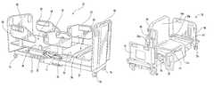
- FIG. 1Ais a side perspective view of a hospital chair bed in the bed configuration, according to some embodiments of the present invention.
- FIG. 1Bis a side perspective view of the hospital bed shown in FIG. 1A with the bed in a side egress chair configuration with stowable stand assist supports according to embodiments of the present invention.
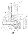
- FIG. 2is a side view of the chair bed shown in FIG. 1B in a stand assist side egress configuration with stowable stand assist supports deployed according to embodiments of the present invention.
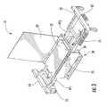
- FIG. 3is a side perspective view of a side egress bed with stowable stand assist supports in a stored configuration (and with patient support side rails removed) according to embodiments of the present invention.
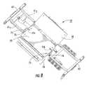
- FIG. 4Ais a partial side perspective view of the bed shown in FIG. 1B with a leg section with foldable and/or pivotable segments according to embodiments of the present invention.
- FIG. 4Bis a partial side perspective view of the bed shown in FIG. 4A with the leg section folded in a chair configuration according to some embodiments of the present invention.
- FIG. 5is a top side-perspective view of a hospital chair bed with two sets of stowable stand assist supports in a deployed operative position according to embodiments of the present invention.
- FIG. 6is a side perspective view of the stand-assist supports of FIG. 5 in respective telescoping extended and retracted positions according to embodiments of the present invention.
- FIG. 7is a front view of a side egress hospital chair bed with support members deployed and the bed in the side egress orientation according to some embodiments of the present invention.
- FIG. 8is a top view of the bed shown in FIG. 6 .
- FIG. 9is a side view of a chair bed in a side egress orientation with stowable stand-assist supports (stored, non-deployed) according to embodiments of the present invention.
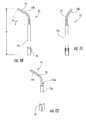
- FIG. 10is a side view of an exemplary stand assist support according to embodiments of the present invention.
- FIG. 11is a side view (shown turned 90 degrees from the view of FIG. 10 ) of the exemplary stand assist support shown in FIG. 10 .
- FIG. 12is a side perspective view of the stand assist support shown in FIGS. 10 and 11 .
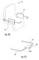
- FIGS. 13A and 13Bare side perspective views of an alternate embodiment showing stowable supports (rails) that can convert to exit-assist supports according to other embodiments of the present invention.
- FIG. 14is a schematic illustration of the bed shown in FIG. 13B illustrating the supports holding supplemental partitions according to some embodiments of the present invention.
- FIG. 15is a schematic illustration of the bed shown in FIG. 13B illustrating the supports holding a table accessory item according to some embodiments of the present invention.
- hospital bedis used broadly herein to refer to a bed for persons in whatever environment the bed is used and is not limited to use in a hospital per se (e.g., a hospital bed may be used in a private home, nursing home, rehab center, short term or long term care facility, outpatient treatment center and the like). It is noted that although certain features of the hospital beds are described with respect to a hospital bed that can be converted into a chair bed, it is contemplated that embodiments are not limited thereto and can be used with any type of hospital bed. Further, although primarily described for use with a side-egress chair bed, embodiments can be used with end-egress chair beds.
- spatially relative termssuch as “under”, “below”, “lower”, “over”, “upper” and the like, may be used herein for ease of description to describe one element or feature's relationship to another element(s) or feature(s) as illustrated in the figures. It will be understood that the spatially relative terms are intended to encompass different orientations of a device in use or operation in addition to the orientation depicted in the figures. For example, if a device in the figures is inverted, elements described as “under” or “beneath” other elements or features would then be oriented “over” the other elements or features. Thus, the exemplary term “under” can encompass both an orientation of “over” and “under”.
- a devicemay be otherwise oriented (rotated 90 degrees or at other orientations) and the spatially relative descriptors used herein interpreted accordingly.
- the terms “upwardly”, “downwardly”, “vertical”, “horizontal” and the likeare used herein for the purpose of explanation only unless specifically indicated otherwise.
- first”, “second”, etc.may be used herein to describe various elements, components, regions, layers and/or sections, these elements, components, regions, layers and/or sections should not be limited by these terms. These terms are only used to distinguish one element, component, region, layer or section from another element, component, region, layer or section. Thus, a “first” element, component, region, layer or section discussed below could also be termed a “second” element, component, region, layer or section without departing from the teachings of the present invention.
- the bedscan be configured with lift mechanisms and patient supports that have structural ratings sufficient to provide lift functions for weight ranges of patients, e.g., between about 100-1200 lbs, typically between about 100-1200 lbs, such as between about 100-1000 lbs or between about 100-500 lbs, and the like, but may also be configured to accommodate larger weight patients and smaller weight patients including bariatric patients.
- a hospital bed 10is illustrated.
- the illustrated bed 10has a base 12 and a rotating frame 14 mounted on the base 12 .
- the frame 14is configured to rotate relative to the base 12 to facilitate side egress from the bed 10 by a patient, as will be described below.
- Casters 16can be mounted to the four corners of the base 12 and facilitate movement of the bed about the hospital or other environment.
- casters 16are locking casters that can be selectively locked to prevent movement of the bed 10 .
- the illustrated bed 10has a patient support surface 18 configured to support a mattress 18 m ( FIG. 2 ) on which a patient is situated.
- the patient support surface 18is supported by the rotating frame 14 and includes a back panel 20 , a seat panel 22 , and a leg panel or section 24 .
- the back panel 20 , seat panel 22 and leg section 24can articulate with respect to each other and may be serially hinged together.
- the back panel 20 and seat panel 22can be pivotally attached to each other by pins, hinges, or other suitable mechanisms well known in the art.
- the seat panel 22 and leg section 24can also be pivotally attached to each other by pins, hinges, or other suitable mechanisms well known in the art.
- the bed 10also can have a first set of patient side rails 30 typically secured to the back panel 20 in spaced-apart relationship and a second set of patient side rails 32 typically secured to the seat panel 22 or leg section 24 in spaced-apart relationship, as illustrated.
- a head board 40can be secured to the base 12 at the head end of the bed 10 and a foot board 42 can be secured to the base 12 at the foot end of the bed 10 , as illustrated.
- the patient support surface 18can be secured to the rotating frame 14 via a transverse rod or pin connection (not illustrated) to facilitate tilting of the patient support surface 18 relative to the rotating frame 14 .
- the rotating frame 14is secured to the base 12 via a lift mechanism 50 ( FIG. 1A , 2 ), such as a double scissors lift.
- the lift mechanism 50is configured to raise and lower the patient support surface 18 , via the rotating frame 14 , relative to the base 12 .
- the lift mechanism 50can be driven by hydraulic cylinders, air cylinders, air bags, and/or other electrical or electromechanical devices, etc.
- the lift mechanism 50can be configured to allow the patient support surface 18 to be raised above and lowered with respect to the base 12 . See, e.g., co-pending U.S. patent application Ser. No. 11/398,098 for examples of rotational and lift components, which is incorporated herein by reference in its entirety.
- the bed 10can include at least one on-board, stowable stand-assist support 75 (shown in FIG. 1B as two, one on each side of the seat section 22 ) that is attached to the base frame 12 .
- One end portion of the support 75can be affixed to a long side of the frame 61 1 ( FIG. 3 ).
- the on-board, stowable stand-assist support(s) 75can be manually or automatically deployed upward so that a patient sitting in the chair bed (after the bed is turned 90 degrees relative to the normal sleeping position/orientation) can contact the handle portions 75 h on the top end portions thereof.
- the (unlock) or deployment or extension of the supportscan be electronically controlled via sensors and monitoring circuits, signal processors, and/or computers and may use actuators, hydraulic or pneumatic cylinders, springs, linkages or other devices known to those of skill in the art.
- the stand-assist supports 75can be configured to inhibit rotation of the bed back to alignment with the long sides of the frame when the stand-assist supports 75 are deployed (e.g., extended).
- the supports 75can be configured to have a low profile to mount to the side frame(s) 61 during non-use and allow the patient support surface 18 to articulate, lift and rotate without interference with the predetermined normal motions of the bed.
- the supports 75can be used with the patient side rails 30 , 32 as shown for example in FIGS. 1B and 2 .
- the leg panel or section 24can be configured to have a plurality of segments that translate relative to each other to be able to take on different orientations when in the chair versus bed positions.
- FIG. 3illustrates that the leg section 24 has at least two adjacent panels 25 , 26 that can move from being horizontal and in co-planar relationship in the bed position to being substantially orthogonal in the side egress chair position.
- the lower panel 26can be substantially horizontal while the other panel 25 is substantially vertical.
- the lower panel 26can extend toward the interior space of the bed/base frame 12 and a smaller portion of the lower panel 26 may reside forward of the upper panel 25 .
- the back panel and seat panelmay disengage from the foot or leg panel and not rotate into the side egress position. See, e.g., U.S. patent application Ser. No. 12/499,896, the contents of which are hereby incorporated by reference as if recited in full herein.
- the leg section 24includes a first panel 25 , a second panel 26 , and a third panel 27 pivotally connected together in series.
- the leg section first panel 25can be pivotally connected to the seat panel 22 of the articulating patient support surface 18 .
- the leg section first, second and third panels 25 , 26 , 27can be in substantially co-planar relationship as illustrated in FIG. 1 .
- the leg section panels 25 , 26 , 27are configured to be able to fold together and/or overlap at least portions of each other when the patient support surface is in a chair configuration, as illustrated in FIG. 4B .
- the leg section panels 25 , 26 , 27have respective different lengths L 1 , L 2 , L 3 .
- the length L 1 of panel 25is greater than the lengths L 2 and L 3 of panels 26 and 27 .
- L 1may be between about twelve inches and about twenty four inches (12′′-24′′).
- the length L 3 of panel 27is greater than the length L 2 of panel 26 , but is less than the length L 1 of panel 25 .
- L 3may be between about ten inches and about twenty inches (10′′-20′′).
- the length L 2 of panel 26is less than both L 1 of panel 25 and L 3 of panel 27 .
- L 2may be between about six inches and about twelve inches (6′′-12′′).
- Other patient support configurations and/or leg section configurationsmay be used.
- the bed 10typically has the back panel 20 , seat panel 22 , and leg section 24 in a horizontal configuration as shown in FIG. 1A , to support a patient in a supine position.
- the back panel 20 , seat panel 22 and leg section 24articulate relative to each other as shown in FIG. 2 , for example by an actuator (e.g., pneumatic or hydraulic cylinder or other suitable mechanism).
- an actuatore.g., pneumatic or hydraulic cylinder or other suitable mechanism.
- the back panel 20 and the seat panel 22can pivot relative to each other until they are substantially orthogonal to each other.
- the articulated patient support surface 18can be placed in a “zero-gravity” configuration or other desirable shape and rotated approximately ninety degrees (90°) to permit side egress from the bed 10 , as illustrated in FIGS. 1B and 3 . Once rotated approximately ninety degrees (90°) to permit side egress from the bed 10 , the articulated patient support surface 18 can then be tilted as a unit, as illustrated in FIG. 1B , until the seat panel 22 is substantially horizontal. At this point, the back panel 20 may be substantially vertical. In some embodiments, the bed 10 can then be further moved to a stand-assist configuration with the seat 20 tilted down about 30 degrees and the back 20 being positioned substantially vertically.
- the first, second, and third panels 25 , 26 , 27 of the leg section 24pivot relative to each other. Tilting of the articulated patient support surface 18 can cause the first, second, and third panels 25 , 26 , 27 to pivot relative to each other such that the third panel 27 is substantially horizontal, the second panel 26 is in overlying, face-to-face contact with the third panel 27 , and the first panel 25 is substantially vertical. This causes a rear portion 27 a of the third panel 27 to extend under the base 12 of the bed, as illustrated in FIG. 4B .
- the third panel 27is substantially out of the way of the feet of a patient who wishes to egress from the bed 10 and/or allows for the bed to accommodate a greater range of patient sizes to exit the bed while contacting the floor (e.g., short and tall patients).
- the leg section first, second and third panels 25 , 26 , 27pivot relative to each other such that, when the patient support surface is in the side egress chair configuration, the third panel is substantially horizontal, the second panel is in overlying, face-to-face contact with the third panel, and the first panel is substantially vertical.
- the leg section first second and third panels 25 , 26 , 27pivot relative to each other such that, when the patient support surface is in a chair configuration, a portion of the third panel extends beneath the base.
- the leg section first, second, and third panels 25 , 26 , 27each have respective different lengths.
- the leg section first panelhas a length that is greater than a length of the second and third panels.
- the side rails 32can be secured to the leg section 24 and may optionally rotate with the leg section 24 so as to be oriented such that a longitudinal direction thereof A 1 is substantially vertical ( FIG. 1B ) when the bed is in a side egress position.
- the side rails 32can be removed prior to rotation or not used on the bed 10 at all.
- the side rails 32can remain on the bed but the stand assist supports 75 are configured to be used as support handles 75 h to help a patient stand up from a sitting position on the support surface 18 .
- the patient support surface 18may then be raised and tilted forward, if necessary, to facilitate patient egress from the support surface 18 (e.g., a “stand-assist” orientation).
- the stand-assist supports 75can be used when the bed 10 is in the chair configuration shown in FIG. 1B , and/or to help patients rise or exit the bed in both side egress configurations (e.g., FIG. 1B and FIG. 2 ), where used.
- the bed 10can be configured with at least one pair of stand-assist supports 75 that stow proximate to (typically against) one long side of the base frame 61 .
- the supports 75can be stowed to reside against an upper surface of the long side of the base frame 61 , one on opposing sides of the seat section 22 (when in the side egress position).
- the handle 75 hcan be oriented to face into the interior space of the bed (when stowed).
- one or both of the supports 75may alternatively optionally store against an upwardly extending (vertical) surface of the long side of the base frame 61 (not shown) under the patient support surface 18 .
- the support 75can be attached to the long side 61 of the base frame 12 via pivot 76 at one end portion 75 a (the end portion away from the handle 75 h ) and may be held in the stow position using a retention member 80 at a medial 75 m or opposing end portion 75 b ( FIG. 4A , 5 ).
- the support 75can be configured with sufficient structural capacity/integrity so that the handle 75 h is accessible by a user and the upper end 75 b does not require any cross-support.
- the retention member 80can be any suitable configuration to releasably hold the support 75 against the frame 12 as is well known to those of skill in the art.
- the retention member 80can comprise a resilient clip with an open front to frictionally engage and release the support 75 from the stowed position.
- the support 75is securely held against (and may be directly against) the frame 61 , but no affirmative lock is required.
- the supports 75can have a primary body 75 p ( FIG. 11 ) that is mounted to the frame 61 to allow a single plane of motion and to be able to affirmatively stop when rotated up and positioned to reside adjacent the seat panel 22 on the corresponding side of the bed 10 without allowing further rotation. That is, the primary body 75 p of each support 75 can be mounted to the frame 61 to have a limited travel from about 0-90 degrees between the stowed and the active positions.
- the handle 75 hcan rotate independently of the primary body 75 p and may be extendable relative thereto.
- the handle 75 hcan have an angular shape with an angle “a” of between about 100-130 degrees, typically about 120 degrees measured from a longitudinally extending segment centerline to a tip thereof ( FIG. 10 ).
- the support 75 and handle 75 hcan be configured to provide the structure necessary to reliably support the weight of typical patients. In some embodiments the support 75 can be configured to accommodate patients having a weight between about 100-500 lbs.
- the handle end 75 hcan include a textured and/or elastomeric gripping surface. Replaceable (textured) end grips can be used where desired (not shown).
- FIG. 5illustrates that the bed 10 can include two pairs of the supports 75 , one on one long side 61 1 and one on the other 61 2 . This allows a user to select one of the different pair of supports 75 to be used depending on which way the bed 10 is rotated for side egress (e.g., in either a left or right direction). In some embodiments, a user can extend both pairs of the supports 75 when the bed is in the side-egress chair configuration, but typically a single pair is used while the other pair remains stowed against or proximate the frame 61 .
- the supports 75can be configured to be adjustable in at least a length dimension (e.g., upwardly) to allow for different size patients.
- the height “H” of the handle 75 hcan be adjustable between about 3-8 inches and may be configured to be able to selectively reside (lock into a desired position) between about 18 inches to about 23 inches above the base frame 61 ( FIG. 10 ).
- the length adjustmentcan be via a telescopic configuration with the handle rod 79 being able to be translated vertically to a desired length and self-lock based on the configuration and frictional engagement of the handle rod 79 and channel 75 ch ( FIG. 12 ).
- a positive locking feature or componentsuch as a spring pin, cotter pin, clevis pin or other locking member/configuration may be used.
- the support 75can include an anti-rotation configuration or member to allow the handle rod 79 to stay in the proper orientation so that the handles 75 h project toward each other across the seat section/panel 22 to define a comfortable patient stand-assist support that is easily accessible by different sized patients at the desired heights.
- the anti-rotationcan be provided by a geometrically shaped channel and a corresponding shaped rod forming a portion of the handle, a D-shaped channel or a slot in the handle that mates with a pin mounted internal to the channel and the like.
- the supports 75may also be mounted to the base frame to allow for lateral adjustment, e.g., the frame can include a lockable track/slot configuration 275 (shown as longitudinally adjustable on the frame for a lateral adjustment with respect to the seat between positions A and B).
- the frame track/slot configuration 275may also or alternatively hold the supports 75 to allow for transverse adjustment (to reside closer the forward edge of the seat section or to reside closer toward the back section).
- one or both of the stand-assist supports 75can be configured to define a cane 75 c with the handle 75 h .
- only one of the stand assist supports 75 in each paircan be used as a cane 75 c and the other stand-assist support has a different end configuration and is mounted to the frame in a different manner.
- the support member 75 defining the cane 75 ccan be released from the frame 61 1 when exiting or after exiting the bed 10 for use by the patient.
- the lower(ground) end of the cane 75 ccan include an anti-slip member 77 that can be added to the cane 75 c prior to use by the patient or may reside on the support proximate the pivot attachment end portion 76 (the latter is shown attached in FIG. 9 ).
- the anti-slip member 77can be an elastomeric cap or film that can be replaced as needed due to use.
- the cane floor contacting endcan be configured with grooves, embossments or other textures to provide an increased friction surface without requiring a separate member 77 .
- the supports 75can be an integral single piece body or may be configured as a multi-piece body. As shown in FIGS. 10-12 , the support 75 includes a primary tubular member 75 p and a telescoping hexagonal rod section 79 that slidably snugly resides in the tubular member and extends a distance upward and angles upward and laterally over toward a patient to define the handle 75 h . However, other configurations of the supports 75 may be used.
- the stand-assist supports 75are mounted to the bed frame 61 and may be able to be used as a mount system for releasably mounting the stand-assist support with handles 75 h as well as different therapeutic or accessory devices in the same support body 75 p when pivoted upward, e.g., slings, braces, cuffs and/or exercise accessories can releasably mount to the primary support body 75 p after the handle 75 h is removed (not shown).
- the support 75can be mounted to the outside of the frame 61 so that the mattress 18 m or support surface 18 does not interfere with deployment of the support 75 .
- FIG. 13A and 13BAn alternative embodiment is shown in FIG. 13A and 13B .
- the stowable supports 75 ′can be stowed adjacent an outer perimeter of the back panel 20 .
- the supports 75 ′can be pivotally attached to a medial and/or lower portion of the back panel 20 (or upper portion of the seat panel) via pivot 20 p .
- the supports 75 ′can pivot downward to be substantially parallel to the seat section 22 of the bed 10 and reside at a distance above the mattress of the seat section 22 as shown in FIG. 13B .
- the supports 75 ′may alternatively be attached to the seat or leg panels so as to be able to rotate with the patient support surface (not shown).
- the bed 10will include two supports 75 ′ as shown, one on each opposing side of the back panel 20 .
- a bedmay include only one of the supports 75 ′.
- the supports 75 ′can be releasably stowed against the bed panel 20 .
- a nurse or other care providercan release one or both of the supports 75 ′ and manually attach the support(s) 75 ′ to the bed, typically at the lower portion of the back panel 20 or at an upper portion of the seat panel 22 to form the side exit rail/assist when the bed is in the chair bed configuration.
- the supports 75 ′can extend a distance above the scat panel 22 and mattress 18 m . Typically, the supports 75 ′ reside at a distance that is between about 3-12 inches above the mattress 18 m of the seat panel 22 .
- the supports 75 ′may also be configured to allow vertical adjustment for the deployed position to accommodate different sized/heights in patients. As shown in FIG. 14 , the supports 75 ′ may alternatively or additionally be configured to cooperate with vertically or upwardly extending partitions 175 that can provide additional barrier structure as appropriate.
- the supports 75 ′can include slots on an outer surface thereof or channels extending that releasably engage upwardly and/or downwardly extending substantially planar shields that provide the partitions 175 .
- the shields or partitions 175may have other shapes and may have different shapes on each side of the seat section or panel 22 .
- the supports 75 ′can have a length that is less than a length of the mattress, typically a length that substantially corresponds to a length of the back panel 20 .
- the supports 75 ′can define safety rails when deployed as shown in FIG. 13B .
- the supports 75 ′may provide a safety feature to inhibit a patient from falling out of the bed sideways when the bed is in the side egress chair position, for example.
- the supports 75 ′can also assist a patient in exiting the bed either in the chair or a stand assist configuration with the seat panel raised relative to the chair position.
- the supports 75 ′can be provided in telescoping configuration for length adjustment.
- the supports 75 ′can also hold other accessory structures for ease of patient access to desired items. As shown in FIG. 15 , the supports 75 ′ can releasably hold tables 160 .
- the tables 160(or partitions 175 , FIG. 14 ) can include BLUETOOTH connections, INTERNET, WIFI or other electrical connections 160 e , including plug-in receptacles for recharging electronic devices, typically patient entertainment or communication devices such as cell phones, computers, televisions and/or MP 3 players such as IPODS.
- the supports 75 ′can also hold other accessory items such as reading supports, mirrors, therapeutic devices and the like.
- strutscan be used to structurally reinforce the supports. The struts can connect a seat section siderail to the corresponding support 75 ′ (not shown).
- the side rails 32 proximate the leg panel 24can translate transversely in and out (toward and away from the back panel 20 ) as shown by the directions of the arrows “T” in FIG. 13A .
- one or both of the lower side rails 24can translate inwardly toward the center of the bed frame to expose the mattress on the leg section 24 to allow a wheel chair closer access to the patient.
- the supports 75 ′can stow snugly against an outer perimeter of the head panel 20 proximate an outer edge portion of the mattress (and under the mattress 18 m ).
- the supports 75 ′can curve at an upper end portion 75 c to follow the contour of the panel 20 and/or mattress 18 m .
- the curve portion 75 ccan extend inwardly when deployed as shown in FIG. 13B .
- the curve portion 75 cis not required but may provide additional handle support for the patient.
- the stand-assist supports curved endcan optionally substantially correspond to a contour at an intersection of a short and long side of the bed frame and/or mattress 18 m .
- the curve 75 cmay have an ergonomic three-dimensional shape for patient comfort/ease of use (such as angled and curved in three dimensions).
- the bedcan be configured to rotate the panels 20 , 22 , 24 and mattress 18 m to the left side as well to allow both right and left side egress.
- the supports 75 ′can include other features as described above for other embodiments, for example, it is contemplated that replaceable hand grips and/or covers can be configured to slide over at least the end portions of the supports 75 ′ (e. g. , the curved portions 75 c where used).
- the outer end(shown as the curved portion 75 c ) may also or alternatively include a textured and/or elastomeric gripping surface. Replaceable (textured) end grips can be used where desired (not shown).
- the supports 75 ′can be configured to provide the structure necessary to reliably support the weight of typical patients. In some embodiments, the supports 75 ′ can accommodate patients having a weight between about 100-500 lbs.
Landscapes
- Health & Medical Sciences (AREA)
- Nursing (AREA)
- Life Sciences & Earth Sciences (AREA)
- Animal Behavior & Ethology (AREA)
- General Health & Medical Sciences (AREA)
- Public Health (AREA)
- Veterinary Medicine (AREA)
- Invalid Beds And Related Equipment (AREA)
Abstract
Description
Claims (29)
Priority Applications (1)
| Application Number | Priority Date | Filing Date | Title |
|---|---|---|---|
| US13/516,271US9265677B2 (en) | 2009-12-23 | 2010-12-03 | Hospital chair beds with stowable stand-assist supports |
Applications Claiming Priority (4)
| Application Number | Priority Date | Filing Date | Title |
|---|---|---|---|
| US28952309P | 2009-12-23 | 2009-12-23 | |
| US35247210P | 2010-06-08 | 2010-06-08 | |
| PCT/US2010/058833WO2011087616A2 (en) | 2009-12-23 | 2010-12-03 | Hospital chair beds with stowable stand-assist supports |
| US13/516,271US9265677B2 (en) | 2009-12-23 | 2010-12-03 | Hospital chair beds with stowable stand-assist supports |
Publications (2)
| Publication Number | Publication Date |
|---|---|
| US20130007960A1 US20130007960A1 (en) | 2013-01-10 |
| US9265677B2true US9265677B2 (en) | 2016-02-23 |
Family
ID=44304868
Family Applications (1)
| Application Number | Title | Priority Date | Filing Date |
|---|---|---|---|
| US13/516,271Expired - Fee RelatedUS9265677B2 (en) | 2009-12-23 | 2010-12-03 | Hospital chair beds with stowable stand-assist supports |
Country Status (2)
| Country | Link |
|---|---|
| US (1) | US9265677B2 (en) |
| WO (1) | WO2011087616A2 (en) |
Cited By (14)
| Publication number | Priority date | Publication date | Assignee | Title |
|---|---|---|---|---|
| WO2018038827A1 (en)* | 2016-08-24 | 2018-03-01 | Cns Solutions, Llc | Methods and apparatus for moving a patient from a reclining position to an upright sitting position |
| US10406053B2 (en)* | 2016-07-15 | 2019-09-10 | Joseph Stanislao | Rotating and articulating sleeping assembly |
| US10470955B2 (en) | 2014-03-11 | 2019-11-12 | Hill-Rom Services, Inc. | Patient bed having translatable siderail for bed exit |
| US10716720B1 (en)* | 2014-05-30 | 2020-07-21 | Harken, Incorporated | Patient transport system |
| US10736431B2 (en)* | 2018-02-01 | 2020-08-11 | Ulife Healthcare Inc. | Modular bed |
| US10898008B2 (en) | 2016-07-26 | 2021-01-26 | Ppj, Llc | Adjustable bed systems with rotating articulating bed frame |
| US10918550B2 (en) | 2016-07-26 | 2021-02-16 | Ppj, Llc | Adjustable bed systems with rotating articulating bed frame |
| US10932974B2 (en) | 2016-07-26 | 2021-03-02 | Ppj, Llc | Adjustable bed systems with rotating articulating bed frame |
| US11052005B2 (en) | 2017-09-19 | 2021-07-06 | Stryker Corporation | Patient support apparatus with handles for patient ambulation |
| US11116680B2 (en) | 2017-09-19 | 2021-09-14 | Stryker Corporation | Patient support apparatus for controlling patient ingress and egress |
| US11160705B2 (en) | 2017-10-20 | 2021-11-02 | Stryker Corporation | Adjustable patient support apparatus for assisted egress and ingress |
| US11877968B1 (en) | 2022-04-26 | 2024-01-23 | Marilyn Roberts | Extendable safety handle for benches |
| USD1027482S1 (en)* | 2021-02-11 | 2024-05-21 | Linet Spol. S.R.O | Bed |
| USD1058214S1 (en)* | 2021-09-15 | 2025-01-21 | Linet Spol. S.R.O. | Bed |
Families Citing this family (18)
| Publication number | Priority date | Publication date | Assignee | Title |
|---|---|---|---|---|
| US8375489B2 (en)* | 2008-07-09 | 2013-02-19 | Piedmont 361, Llc | Hospital chair beds with drop foot section |
| US9265677B2 (en)* | 2009-12-23 | 2016-02-23 | Piedmont 361, Llc | Hospital chair beds with stowable stand-assist supports |
| WO2012031159A2 (en)* | 2010-09-01 | 2012-03-08 | Tekulve Daniel R | Bed with pivotable bed surface |
| US8640285B2 (en)* | 2010-11-22 | 2014-02-04 | Hill-Rom Services, Inc. | Hospital bed seat section articulation for chair egress |
| US20120312196A1 (en)* | 2011-06-08 | 2012-12-13 | Newkirk David C | Overbed table with wireless power transfer |
| US10188567B2 (en) | 2014-10-30 | 2019-01-29 | Byron Wade Wurdeman | Hospital chair beds with extendable/retractable foot sections |
| KR101674286B1 (en)* | 2015-01-15 | 2016-11-22 | 인제대학교 산학협력단 | A bed for patients |
| US10667976B2 (en)* | 2015-05-28 | 2020-06-02 | Medical Positioning, Inc. | Low clearance medical imaging chair |
| US11020295B2 (en) | 2015-12-22 | 2021-06-01 | Stryker Corporation | Patient support systems and methods for assisting caregivers with patient care |
| US10813806B2 (en) | 2016-05-24 | 2020-10-27 | Stryker Corporation | Medical support apparatus with stand assistance |
| MX2020009052A (en)* | 2018-03-01 | 2021-01-15 | Ppj Llc | Adjustable bed systems with rotating articulating bed frame. |
| EP3692966A1 (en)* | 2019-02-07 | 2020-08-12 | Rotobed ApS | Bed system and related method |
| GB2586782B (en)* | 2019-08-29 | 2021-11-10 | Blakeley Jeff | Pivotable bed |
| CN110433043B (en)* | 2019-09-20 | 2021-05-07 | 湖北省妇幼保健院 | Pregnant woman nursing bed |
| GB201917221D0 (en)* | 2019-11-26 | 2020-01-08 | Laybrook Ltd | Adjustable beds |
| CN111166579A (en)* | 2019-12-25 | 2020-05-19 | 刘悦可 | Power boosting bed |
| CN112336546A (en)* | 2020-11-05 | 2021-02-09 | 姬国霞 | Device for assisting patient in ward to get up |
| CN113397870A (en)* | 2021-06-04 | 2021-09-17 | 郑州大学第一附属医院 | Nursing bed with auxiliary getting-off function |
Citations (93)
| Publication number | Priority date | Publication date | Assignee | Title |
|---|---|---|---|---|
| US1778698A (en) | 1928-10-10 | 1930-10-14 | Frank S Betz Company | Obstetrical table |
| US2556591A (en) | 1946-02-06 | 1951-06-12 | Walter M Loxley | Invalid bed |
| US2585660A (en) | 1949-01-31 | 1952-02-12 | Otto B Kjos | Patient's bedease |
| US2722017A (en) | 1951-11-16 | 1955-11-01 | Hill Rom Co Inc | Side guards for hospital beds |
| US2766463A (en) | 1952-02-19 | 1956-10-16 | Bendersky Sadie | Means for converting a bed to a chair |
| US3053568A (en) | 1960-02-05 | 1962-09-11 | Clarence A Silva | Chair-bed combination |
| US3063066A (en) | 1958-12-17 | 1962-11-13 | Hildegarde V Peck | Sidegate for beds |
| US3112500A (en)* | 1961-05-24 | 1963-12-03 | Benjamin R F Macdonald | Hospital bed |
| US3239853A (en)* | 1962-01-15 | 1966-03-15 | Benjamin R F Macdonald | Convertible hospital bed-chair |
| US3261639A (en) | 1963-12-26 | 1966-07-19 | Robert E Phillips | Lounge device |
| US3286283A (en) | 1964-12-31 | 1966-11-22 | Joseph M Bertoldo | Hand grip attachment for hospital-type beds |
| US3585659A (en) | 1969-10-15 | 1971-06-22 | Hill Rom Co Inc | Safety side guard for hospital beds |
| US3821821A (en) | 1972-08-21 | 1974-07-02 | Hill Rom Co Inc | Electrically operable hospital bed |
| US3930273A (en) | 1973-08-30 | 1976-01-06 | Affiliated Hospital Products, Inc. | Bed safety side rail arrangement |
| US4186456A (en) | 1978-07-14 | 1980-02-05 | American Hospital Supply Corporation | Rail system for bed or stretcher |
| US4376317A (en) | 1981-07-06 | 1983-03-15 | Burke, Inc. | Foldable step arrangement for beds |
| US4409695A (en) | 1981-02-03 | 1983-10-18 | Burke, Inc. | Adjustable bed for morbidly obese patients |
| US4439880A (en) | 1980-09-18 | 1984-04-03 | Burlington Industries, Inc. | Geriatric bed construction with sideguards |
| US4559656A (en) | 1982-12-28 | 1985-12-24 | Hill-Rom Company, Inc. | Hospital bed with a weight-distributing lever system |
| US4771492A (en) | 1987-02-25 | 1988-09-20 | Paine Donald A | Trip bar for hospital bed crib side |
| US4787104A (en) | 1984-10-18 | 1988-11-29 | Grantham Frederick W | Convertible hospital bed |
| US4932090A (en) | 1989-04-12 | 1990-06-12 | Johansson Paul J | Movable support bar |
| US5060327A (en) | 1990-10-18 | 1991-10-29 | Hill-Rom Company, Inc. | Labor grips for birthing bed |
| JPH0515556B2 (en) | 1988-12-26 | 1993-03-01 | Kogyo Gijutsuin | |
| US5195200A (en) | 1992-04-17 | 1993-03-23 | Thomas Leoutsakos | Manual support apparatus attachable to a bedframe |
| USD336578S (en) | 1990-12-14 | 1993-06-22 | Hill-Rom Company, Inc. | Hand grip for a birthing bed |
| US5257426A (en) | 1992-04-17 | 1993-11-02 | Thomas Leoutsakos | Manual support apparatus attachable to a bedframe |
| US5337430A (en) | 1993-04-28 | 1994-08-16 | Schlein Allen P | Device for assisting a person to transfer into and from a bed |
| US5384927A (en) | 1993-01-27 | 1995-01-31 | Canadian Aging & Rehabilitation Product Development Corp. | Security rail attachment for a bed |
| US5394580A (en) | 1993-06-11 | 1995-03-07 | Hill-Rom Company, Inc. | Hospital bed with three position patient side guards |
| US5398357A (en) | 1993-06-03 | 1995-03-21 | Hill-Rom Company, Inc. | Hospital bed convertible to chair configuration |
| US5418988A (en) | 1989-06-26 | 1995-05-30 | Iura; Tadashi | Rotary bed with inwardly pivotable handrails |
| US5479666A (en) | 1994-01-25 | 1996-01-02 | Hill-Rom Company, Inc. | Foot egress chair bed |
| US5497518A (en)* | 1992-05-22 | 1996-03-12 | Iura; Tadashi | Rotary bed |
| US5507050A (en) | 1994-04-26 | 1996-04-16 | Welner; Sandra L. | Examination table |
| US5513406A (en) | 1994-04-21 | 1996-05-07 | Hill-Rom Company, Inc. | Modular hospital bed and method of patient handling |
| EP0780075A1 (en)* | 1995-12-18 | 1997-06-25 | Le Couviour Sa | Bed slide guard |
| US5678267A (en) | 1995-07-11 | 1997-10-21 | Kinder; Florence E. | Medical examination table handle system |
| US5680661A (en) | 1990-05-16 | 1997-10-28 | Hill-Rom, Inc. | Hospital bed with user care apparatus |
| EP0801915B1 (en) | 1996-04-11 | 1997-12-10 | Le Couviour | Bed |
| US5715548A (en) | 1994-01-25 | 1998-02-10 | Hill-Rom, Inc. | Chair bed |
| US5732423A (en) | 1995-08-04 | 1998-03-31 | Hill-Rom, Inc. | Bed side rails |
| US5787530A (en) | 1995-09-29 | 1998-08-04 | Brix; Ruth | Apparatus and method for bed access assistance |
| US5878452A (en) | 1996-12-03 | 1999-03-09 | Hill-Rom, Inc. | Long term care bed controls |
| US6058531A (en) | 1997-05-23 | 2000-05-09 | Carroll Intelli Corp. | Dual-position assist and guard rail for beds |
| USD427465S (en) | 1999-03-17 | 2000-07-04 | Bel-Art Products, Inc. | Handle structure with pockets therein |
| US6154899A (en) | 1998-10-19 | 2000-12-05 | Hill-Rom, Inc. | Resident transfer chair |
| US6240583B1 (en) | 1996-12-03 | 2001-06-05 | Hill-Rom, Inc. | Ambulatory assist arm for a bed |
| USD445614S1 (en) | 1999-09-14 | 2001-07-31 | Sunrise Medical Ccg, Inc. | Pivotable support for an articulated bed |
| US6363552B1 (en) | 2000-03-17 | 2002-04-02 | Hill-Rom Services, Inc. | Bed siderail |
| US6367104B1 (en) | 2000-07-07 | 2002-04-09 | Medical Positioning, Inc. | Patient support apparatus and method for performing decubitus breast biopsy |
| US6374436B1 (en) | 1994-01-25 | 2002-04-23 | Hill-Rom Services, Inc. | Hospital bed |
| US6397416B2 (en) | 1999-08-12 | 2002-06-04 | Hill-Rom Services, Inc. | Ambulatory assist arm for a bed |
| US6487735B1 (en) | 1999-01-22 | 2002-12-03 | Hill-Rom Services, Inc. | Bed enclosure |
| US20030086752A1 (en) | 1998-11-12 | 2003-05-08 | Lemole John M. | Anti-pinch knuckle for bidirectional sleeve |
| USD475559S1 (en) | 2002-06-07 | 2003-06-10 | Carroll Intelli Corp. | Assist rail |
| US6611979B2 (en) | 1997-09-23 | 2003-09-02 | Hill-Rom Services, Inc. | Mattress having a retractable foot section |
| US6629325B2 (en) | 2000-12-20 | 2003-10-07 | Thomas Heavrin | Enabler cover for rotatable hand grip |
| US6684420B2 (en) | 2001-04-27 | 2004-02-03 | Hill-Rom Services, Inc. | Crib apparatus |
| US6691348B2 (en) | 2001-02-26 | 2004-02-17 | Stephen B. Plummer | Bed with adjustable positions |
| US6728985B2 (en) | 2001-08-15 | 2004-05-04 | Hill-Rom Services, Inc. | Ambulatory assist arm apparatus |
| US6807695B1 (en)* | 2003-05-19 | 2004-10-26 | Stryker Corporation | Maternity patient support |
| US6851142B2 (en) | 2002-07-10 | 2005-02-08 | Stryker Corporation | Patient supporting apparatus with siderail |
| US6874179B2 (en) | 2000-10-19 | 2005-04-05 | Hill-Rom S.A.S. | Bed with articulated barrier elements |
| US6886196B2 (en) | 2002-12-13 | 2005-05-03 | Cosco Management, Inc. | Bed rail with fold controller |
| US6893386B2 (en) | 2002-06-04 | 2005-05-17 | Chakri Charoenchit | Physical therapy chair-bed for paralytic patients |
| US20050102754A1 (en) | 2002-01-08 | 2005-05-19 | Hans-Peter Barthelt | Rotating bed with improved stability |
| US20050120485A1 (en)* | 2002-03-05 | 2005-06-09 | Gemeline Sebastien | Handle for hospital bed |
| US6912746B2 (en) | 2001-11-17 | 2005-07-05 | Medi-Plinth Limited | Bed |
| US6961972B2 (en) | 2001-10-17 | 2005-11-08 | Gordon Zachary Pendell | Apparatus to aid in entering and exiting a bed |
| US20060059621A1 (en) | 2004-09-13 | 2006-03-23 | Craig Poulos | Siderail for hospital bed |
| US7017208B2 (en) | 1995-08-04 | 2006-03-28 | Hill-Rom Services, Inc. | Hospital bed |
| US7032265B2 (en) | 1998-09-09 | 2006-04-25 | Standers, Inc. | Assist device for getting into and out of sitting or prone positions on beds and similar furniture |
| US20060085914A1 (en) | 2004-06-14 | 2006-04-27 | Steve Peterson | Adjustable bed for bariatric patients |
| USD520783S1 (en) | 2004-10-01 | 2006-05-16 | M.C. Healthcare Products Inc. | Rotating assist rail |
| US7073220B2 (en) | 2002-09-06 | 2006-07-11 | Hill-Rom Services, Inc. | Bed siderail having a latch |
| US20060230540A1 (en) | 2003-05-22 | 2006-10-19 | Mary Whelan | Patient hand support aid for bed |
| US7150058B2 (en) | 2003-02-28 | 2006-12-19 | Sunrise Medical Hhg Inc. | Assist handle assembly for beds |
| US20070017029A1 (en) | 2005-04-06 | 2007-01-25 | Wurdeman Byron W | Hospital beds with a rotating sleep surface that can translate into a chair configuration |
| US7171709B2 (en) | 1999-12-13 | 2007-02-06 | Hill-Rom Services, Inc. | Accessories for a patient support apparatus |
| US7197779B2 (en) | 2004-11-12 | 2007-04-03 | Medical Equipment & Supplies Discount Center Inc., Two | Side rail assembly for beds |
| US7426760B2 (en) | 1995-01-31 | 2008-09-23 | Kci Licensing, Inc. | Bariatric bed apparatus and methods |
| US7458119B2 (en) | 2004-07-30 | 2008-12-02 | Hill-Rom Services, Inc. | Bed having a chair egress position |
| US7467427B1 (en) | 2007-07-03 | 2008-12-23 | Optima Healthcare Inc. | Handrail means of bed frame |
| US20090007333A1 (en) | 2007-07-06 | 2009-01-08 | Pascal Guguin | Patient bed with a retractable side barrier |
| US7513000B2 (en) | 2005-07-28 | 2009-04-07 | The Brewer Company, Llc | Medical examination table |
| US20090126114A1 (en)* | 2004-11-30 | 2009-05-21 | Jiri Kral | Mobilization handrail and bed equipped with this mobilization handrail |
| EP2074910A2 (en) | 2004-09-13 | 2009-07-01 | Kreg Medical, Inc. | Siderail for hospital bed |
| US20100064439A1 (en) | 2008-09-12 | 2010-03-18 | Sohrab Soltani | Hospital chair beds with articulating foot sections |
| US7802331B2 (en)* | 2005-05-04 | 2010-09-28 | Transitions Industries, Inc. | Tilting furniture |
| WO2011087616A2 (en)* | 2009-12-23 | 2011-07-21 | Piedmont Global Solutions, Inc. | Hospital chair beds with stowable stand-assist supports |
| WO2012031159A2 (en)* | 2010-09-01 | 2012-03-08 | Tekulve Daniel R | Bed with pivotable bed surface |
| US8375489B2 (en) | 2008-07-09 | 2013-02-19 | Piedmont 361, Llc | Hospital chair beds with drop foot section |
- 2010
- 2010-12-03USUS13/516,271patent/US9265677B2/ennot_activeExpired - Fee Related
- 2010-12-03WOPCT/US2010/058833patent/WO2011087616A2/enactiveApplication Filing
Patent Citations (118)
| Publication number | Priority date | Publication date | Assignee | Title |
|---|---|---|---|---|
| US1778698A (en) | 1928-10-10 | 1930-10-14 | Frank S Betz Company | Obstetrical table |
| US2556591A (en) | 1946-02-06 | 1951-06-12 | Walter M Loxley | Invalid bed |
| US2585660A (en) | 1949-01-31 | 1952-02-12 | Otto B Kjos | Patient's bedease |
| US2722017A (en) | 1951-11-16 | 1955-11-01 | Hill Rom Co Inc | Side guards for hospital beds |
| US2766463A (en) | 1952-02-19 | 1956-10-16 | Bendersky Sadie | Means for converting a bed to a chair |
| US3063066A (en) | 1958-12-17 | 1962-11-13 | Hildegarde V Peck | Sidegate for beds |
| US3053568A (en) | 1960-02-05 | 1962-09-11 | Clarence A Silva | Chair-bed combination |
| US3112500A (en)* | 1961-05-24 | 1963-12-03 | Benjamin R F Macdonald | Hospital bed |
| US3239853A (en)* | 1962-01-15 | 1966-03-15 | Benjamin R F Macdonald | Convertible hospital bed-chair |
| US3261639A (en) | 1963-12-26 | 1966-07-19 | Robert E Phillips | Lounge device |
| US3286283A (en) | 1964-12-31 | 1966-11-22 | Joseph M Bertoldo | Hand grip attachment for hospital-type beds |
| US3585659A (en) | 1969-10-15 | 1971-06-22 | Hill Rom Co Inc | Safety side guard for hospital beds |
| US3821821A (en) | 1972-08-21 | 1974-07-02 | Hill Rom Co Inc | Electrically operable hospital bed |
| US3930273A (en) | 1973-08-30 | 1976-01-06 | Affiliated Hospital Products, Inc. | Bed safety side rail arrangement |
| US4186456A (en) | 1978-07-14 | 1980-02-05 | American Hospital Supply Corporation | Rail system for bed or stretcher |
| US4439880A (en) | 1980-09-18 | 1984-04-03 | Burlington Industries, Inc. | Geriatric bed construction with sideguards |
| US4409695A (en) | 1981-02-03 | 1983-10-18 | Burke, Inc. | Adjustable bed for morbidly obese patients |
| US4376317A (en) | 1981-07-06 | 1983-03-15 | Burke, Inc. | Foldable step arrangement for beds |
| US4559656A (en) | 1982-12-28 | 1985-12-24 | Hill-Rom Company, Inc. | Hospital bed with a weight-distributing lever system |
| US4787104A (en) | 1984-10-18 | 1988-11-29 | Grantham Frederick W | Convertible hospital bed |
| US4771492A (en) | 1987-02-25 | 1988-09-20 | Paine Donald A | Trip bar for hospital bed crib side |
| JPH0515556B2 (en) | 1988-12-26 | 1993-03-01 | Kogyo Gijutsuin | |
| US4932090A (en) | 1989-04-12 | 1990-06-12 | Johansson Paul J | Movable support bar |
| US5425151A (en) | 1989-06-26 | 1995-06-20 | Iura; Tadashi | Rotary, invalid bed |
| US5418988A (en) | 1989-06-26 | 1995-05-30 | Iura; Tadashi | Rotary bed with inwardly pivotable handrails |
| US5444883A (en) | 1989-06-26 | 1995-08-29 | Iura; Tadashi | Rotary, invalid bed |
| US6725474B2 (en) | 1990-05-16 | 2004-04-27 | Hill-Rom Services, Inc. | Hospital bed |
| US5680661A (en) | 1990-05-16 | 1997-10-28 | Hill-Rom, Inc. | Hospital bed with user care apparatus |
| US5060327A (en) | 1990-10-18 | 1991-10-29 | Hill-Rom Company, Inc. | Labor grips for birthing bed |
| USD336578S (en) | 1990-12-14 | 1993-06-22 | Hill-Rom Company, Inc. | Hand grip for a birthing bed |
| US5257426A (en) | 1992-04-17 | 1993-11-02 | Thomas Leoutsakos | Manual support apparatus attachable to a bedframe |
| US5195200A (en) | 1992-04-17 | 1993-03-23 | Thomas Leoutsakos | Manual support apparatus attachable to a bedframe |
| US5497518A (en)* | 1992-05-22 | 1996-03-12 | Iura; Tadashi | Rotary bed |
| US5384927A (en) | 1993-01-27 | 1995-01-31 | Canadian Aging & Rehabilitation Product Development Corp. | Security rail attachment for a bed |
| US5337430A (en) | 1993-04-28 | 1994-08-16 | Schlein Allen P | Device for assisting a person to transfer into and from a bed |
| US5398357A (en) | 1993-06-03 | 1995-03-21 | Hill-Rom Company, Inc. | Hospital bed convertible to chair configuration |
| US5394580A (en) | 1993-06-11 | 1995-03-07 | Hill-Rom Company, Inc. | Hospital bed with three position patient side guards |
| US5479666A (en) | 1994-01-25 | 1996-01-02 | Hill-Rom Company, Inc. | Foot egress chair bed |
| US6694548B2 (en) | 1994-01-25 | 2004-02-24 | Hill-Rom Services, Inc. | Hospital bed |
| US6374436B1 (en) | 1994-01-25 | 2002-04-23 | Hill-Rom Services, Inc. | Hospital bed |
| US5715548A (en) | 1994-01-25 | 1998-02-10 | Hill-Rom, Inc. | Chair bed |
| US6163903A (en) | 1994-01-25 | 2000-12-26 | Hill-Rom Inc. | Chair bed |
| US5513406A (en) | 1994-04-21 | 1996-05-07 | Hill-Rom Company, Inc. | Modular hospital bed and method of patient handling |
| US5507050A (en) | 1994-04-26 | 1996-04-16 | Welner; Sandra L. | Examination table |
| US7426760B2 (en) | 1995-01-31 | 2008-09-23 | Kci Licensing, Inc. | Bariatric bed apparatus and methods |
| US5678267A (en) | 1995-07-11 | 1997-10-21 | Kinder; Florence E. | Medical examination table handle system |
| US5732423A (en) | 1995-08-04 | 1998-03-31 | Hill-Rom, Inc. | Bed side rails |
| US7017208B2 (en) | 1995-08-04 | 2006-03-28 | Hill-Rom Services, Inc. | Hospital bed |
| US6182310B1 (en) | 1995-08-04 | 2001-02-06 | Hill-Rom, Inc. | Bed side rails |
| US5787530A (en) | 1995-09-29 | 1998-08-04 | Brix; Ruth | Apparatus and method for bed access assistance |
| EP0780075A1 (en)* | 1995-12-18 | 1997-06-25 | Le Couviour Sa | Bed slide guard |
| EP0801915B1 (en) | 1996-04-11 | 1997-12-10 | Le Couviour | Bed |
| US6240583B1 (en) | 1996-12-03 | 2001-06-05 | Hill-Rom, Inc. | Ambulatory assist arm for a bed |
| US6185767B1 (en) | 1996-12-03 | 2001-02-13 | Hill-Rom, Inc. | Controls for a bed |
| US5878452A (en) | 1996-12-03 | 1999-03-09 | Hill-Rom, Inc. | Long term care bed controls |
| US6829793B2 (en) | 1996-12-03 | 2004-12-14 | Hill - Rom Services, Inc. | Bed siderail extender apparatus |
| US6058531A (en) | 1997-05-23 | 2000-05-09 | Carroll Intelli Corp. | Dual-position assist and guard rail for beds |
| US6611979B2 (en) | 1997-09-23 | 2003-09-02 | Hill-Rom Services, Inc. | Mattress having a retractable foot section |
| US7234182B2 (en) | 1998-09-09 | 2007-06-26 | Standers, Inc. | Assist device for getting into and out of sitting or reclined positions |
| US7032265B2 (en) | 1998-09-09 | 2006-04-25 | Standers, Inc. | Assist device for getting into and out of sitting or prone positions on beds and similar furniture |
| US7472445B2 (en) | 1998-09-09 | 2009-01-06 | Standers, Inc. | Assist device for getting into and out of sitting or prone positions on beds and similar furniture |
| US6185769B1 (en) | 1998-10-19 | 2001-02-13 | Hill-Rom, Inc. | Resident transfer chair |
| US6154899A (en) | 1998-10-19 | 2000-12-05 | Hill-Rom, Inc. | Resident transfer chair |
| US20030086752A1 (en) | 1998-11-12 | 2003-05-08 | Lemole John M. | Anti-pinch knuckle for bidirectional sleeve |
| US6487735B1 (en) | 1999-01-22 | 2002-12-03 | Hill-Rom Services, Inc. | Bed enclosure |
| USD427465S (en) | 1999-03-17 | 2000-07-04 | Bel-Art Products, Inc. | Handle structure with pockets therein |
| US6397416B2 (en) | 1999-08-12 | 2002-06-04 | Hill-Rom Services, Inc. | Ambulatory assist arm for a bed |
| USD445614S1 (en) | 1999-09-14 | 2001-07-31 | Sunrise Medical Ccg, Inc. | Pivotable support for an articulated bed |
| US7171709B2 (en) | 1999-12-13 | 2007-02-06 | Hill-Rom Services, Inc. | Accessories for a patient support apparatus |
| US6880189B2 (en) | 1999-12-29 | 2005-04-19 | Hill-Rom Services, Inc. | Patient support |
| US6978500B2 (en) | 1999-12-29 | 2005-12-27 | Hill-Rom Services, Inc. | Foot controls for a bed |
| US6658680B2 (en) | 1999-12-29 | 2003-12-09 | Hill-Rom Services, Inc. | Hospital bed |
| US6691346B2 (en) | 1999-12-29 | 2004-02-17 | Hill-Rom Services, Inc. | Foot controls for a bed |
| US6363552B1 (en) | 2000-03-17 | 2002-04-02 | Hill-Rom Services, Inc. | Bed siderail |
| US6640360B2 (en) | 2000-03-17 | 2003-11-04 | Hill-Rom Services, Inc. | Bed siderail |
| US6367104B1 (en) | 2000-07-07 | 2002-04-09 | Medical Positioning, Inc. | Patient support apparatus and method for performing decubitus breast biopsy |
| US7237284B2 (en) | 2000-10-19 | 2007-07-03 | Hill-Rom S.A.S. | Bed with articulated barrier elements |
| US6874179B2 (en) | 2000-10-19 | 2005-04-05 | Hill-Rom S.A.S. | Bed with articulated barrier elements |
| US7350248B2 (en) | 2000-10-19 | 2008-04-01 | Hill-Rom Sas | Bed with articulated barrier elements |
| US6629325B2 (en) | 2000-12-20 | 2003-10-07 | Thomas Heavrin | Enabler cover for rotatable hand grip |
| US6691348B2 (en) | 2001-02-26 | 2004-02-17 | Stephen B. Plummer | Bed with adjustable positions |
| US6684420B2 (en) | 2001-04-27 | 2004-02-03 | Hill-Rom Services, Inc. | Crib apparatus |
| US6728985B2 (en) | 2001-08-15 | 2004-05-04 | Hill-Rom Services, Inc. | Ambulatory assist arm apparatus |
| US6961972B2 (en) | 2001-10-17 | 2005-11-08 | Gordon Zachary Pendell | Apparatus to aid in entering and exiting a bed |
| US6912746B2 (en) | 2001-11-17 | 2005-07-05 | Medi-Plinth Limited | Bed |
| US20050102754A1 (en) | 2002-01-08 | 2005-05-19 | Hans-Peter Barthelt | Rotating bed with improved stability |
| US20050120485A1 (en)* | 2002-03-05 | 2005-06-09 | Gemeline Sebastien | Handle for hospital bed |
| US7039971B2 (en) | 2002-03-05 | 2006-05-09 | Hill-Rom Services, Inc. | Handle for hospital bed |
| US6893386B2 (en) | 2002-06-04 | 2005-05-17 | Chakri Charoenchit | Physical therapy chair-bed for paralytic patients |
| USD475559S1 (en) | 2002-06-07 | 2003-06-10 | Carroll Intelli Corp. | Assist rail |
| US6851142B2 (en) | 2002-07-10 | 2005-02-08 | Stryker Corporation | Patient supporting apparatus with siderail |
| US7073220B2 (en) | 2002-09-06 | 2006-07-11 | Hill-Rom Services, Inc. | Bed siderail having a latch |
| US7028354B2 (en) | 2002-12-13 | 2006-04-18 | Cosco Management, Inc. | Bed rail and clamp |
| US6886196B2 (en) | 2002-12-13 | 2005-05-03 | Cosco Management, Inc. | Bed rail with fold controller |
| US6934984B2 (en) | 2002-12-13 | 2005-08-30 | Cosco Management, Inc. | Bed rail with clamping force indicator |
| US7024708B2 (en) | 2002-12-13 | 2006-04-11 | Cosco Management, Inc. | Bed rail |
| US7150058B2 (en) | 2003-02-28 | 2006-12-19 | Sunrise Medical Hhg Inc. | Assist handle assembly for beds |
| US6807695B1 (en)* | 2003-05-19 | 2004-10-26 | Stryker Corporation | Maternity patient support |
| US20060230540A1 (en) | 2003-05-22 | 2006-10-19 | Mary Whelan | Patient hand support aid for bed |
| US20060085914A1 (en) | 2004-06-14 | 2006-04-27 | Steve Peterson | Adjustable bed for bariatric patients |
| US7458119B2 (en) | 2004-07-30 | 2008-12-02 | Hill-Rom Services, Inc. | Bed having a chair egress position |
| US20060059621A1 (en) | 2004-09-13 | 2006-03-23 | Craig Poulos | Siderail for hospital bed |
| US7676862B2 (en) | 2004-09-13 | 2010-03-16 | Kreg Medical, Inc. | Siderail for hospital bed |
| EP2074910A2 (en) | 2004-09-13 | 2009-07-01 | Kreg Medical, Inc. | Siderail for hospital bed |
| USD520783S1 (en) | 2004-10-01 | 2006-05-16 | M.C. Healthcare Products Inc. | Rotating assist rail |
| US7197779B2 (en) | 2004-11-12 | 2007-04-03 | Medical Equipment & Supplies Discount Center Inc., Two | Side rail assembly for beds |
| US20090126114A1 (en)* | 2004-11-30 | 2009-05-21 | Jiri Kral | Mobilization handrail and bed equipped with this mobilization handrail |
| US20070017029A1 (en) | 2005-04-06 | 2007-01-25 | Wurdeman Byron W | Hospital beds with a rotating sleep surface that can translate into a chair configuration |
| US7802331B2 (en)* | 2005-05-04 | 2010-09-28 | Transitions Industries, Inc. | Tilting furniture |
| US7513000B2 (en) | 2005-07-28 | 2009-04-07 | The Brewer Company, Llc | Medical examination table |
| US7467427B1 (en) | 2007-07-03 | 2008-12-23 | Optima Healthcare Inc. | Handrail means of bed frame |
| US20090007333A1 (en) | 2007-07-06 | 2009-01-08 | Pascal Guguin | Patient bed with a retractable side barrier |
| US8375489B2 (en) | 2008-07-09 | 2013-02-19 | Piedmont 361, Llc | Hospital chair beds with drop foot section |
| US20130125310A1 (en) | 2008-07-09 | 2013-05-23 | Piedmont 361, Llc | Hospital chair beds with drop foot section |
| US20100064439A1 (en) | 2008-09-12 | 2010-03-18 | Sohrab Soltani | Hospital chair beds with articulating foot sections |
| US8495774B2 (en)* | 2008-09-12 | 2013-07-30 | Piedmont 361, Llc | Hospital chair beds with articulating foot sections |
| WO2011087616A2 (en)* | 2009-12-23 | 2011-07-21 | Piedmont Global Solutions, Inc. | Hospital chair beds with stowable stand-assist supports |
| WO2012031159A2 (en)* | 2010-09-01 | 2012-03-08 | Tekulve Daniel R | Bed with pivotable bed surface |
Non-Patent Citations (1)
| Title |
|---|
| International Search Report for corresponding PCT application No. PCT/US2010/058833, Date of mailing Aug. 22, 2011. |
Cited By (18)
| Publication number | Priority date | Publication date | Assignee | Title |
|---|---|---|---|---|
| US10470955B2 (en) | 2014-03-11 | 2019-11-12 | Hill-Rom Services, Inc. | Patient bed having translatable siderail for bed exit |
| US10716720B1 (en)* | 2014-05-30 | 2020-07-21 | Harken, Incorporated | Patient transport system |
| US10881560B1 (en)* | 2014-05-30 | 2021-01-05 | Harken, Incorporated | Patient transport system |
| US10406053B2 (en)* | 2016-07-15 | 2019-09-10 | Joseph Stanislao | Rotating and articulating sleeping assembly |
| US10918550B2 (en) | 2016-07-26 | 2021-02-16 | Ppj, Llc | Adjustable bed systems with rotating articulating bed frame |
| US10932974B2 (en) | 2016-07-26 | 2021-03-02 | Ppj, Llc | Adjustable bed systems with rotating articulating bed frame |
| US10898008B2 (en) | 2016-07-26 | 2021-01-26 | Ppj, Llc | Adjustable bed systems with rotating articulating bed frame |
| US10363187B2 (en) | 2016-08-24 | 2019-07-30 | Cns Solutions, Llc | Methods and apparatus for moving a patient from a reclining position to an upright sitting position |
| WO2018038827A1 (en)* | 2016-08-24 | 2018-03-01 | Cns Solutions, Llc | Methods and apparatus for moving a patient from a reclining position to an upright sitting position |
| US11116680B2 (en) | 2017-09-19 | 2021-09-14 | Stryker Corporation | Patient support apparatus for controlling patient ingress and egress |
| US11052005B2 (en) | 2017-09-19 | 2021-07-06 | Stryker Corporation | Patient support apparatus with handles for patient ambulation |
| US11723821B2 (en) | 2017-09-19 | 2023-08-15 | Stryker Corporation | Patient support apparatus for controlling patient ingress and egress |
| US11160705B2 (en) | 2017-10-20 | 2021-11-02 | Stryker Corporation | Adjustable patient support apparatus for assisted egress and ingress |
| US11806290B2 (en) | 2017-10-20 | 2023-11-07 | Stryker Corporation | Adjustable patient support apparatus for assisted egress and ingress |
| US10736431B2 (en)* | 2018-02-01 | 2020-08-11 | Ulife Healthcare Inc. | Modular bed |
| USD1027482S1 (en)* | 2021-02-11 | 2024-05-21 | Linet Spol. S.R.O | Bed |
| USD1058214S1 (en)* | 2021-09-15 | 2025-01-21 | Linet Spol. S.R.O. | Bed |
| US11877968B1 (en) | 2022-04-26 | 2024-01-23 | Marilyn Roberts | Extendable safety handle for benches |
Also Published As
| Publication number | Publication date |
|---|---|
| WO2011087616A2 (en) | 2011-07-21 |
| US20130007960A1 (en) | 2013-01-10 |
| WO2011087616A3 (en) | 2011-10-13 |
Similar Documents
| Publication | Publication Date | Title |
|---|---|---|
| US9265677B2 (en) | Hospital chair beds with stowable stand-assist supports | |
| US8495774B2 (en) | Hospital chair beds with articulating foot sections | |
| JP4231549B2 (en) | A bed where the patient can get out of the end of the leg | |
| US8745786B2 (en) | Siderail assembly for patient support apparatus | |
| US10188567B2 (en) | Hospital chair beds with extendable/retractable foot sections | |
| US7581265B1 (en) | Roll-in chair cot with three cot height positions | |
| US9173797B2 (en) | Siderail assembly for patient support apparatus | |
| US20120198628A1 (en) | Manually removable foot section | |
| US20120124746A1 (en) | Patient support apparatus with egress units | |
| US20130111667A1 (en) | Multi-Functional, Convertible Treatment-Table | |
| US7913334B2 (en) | Bed with a lateral barrier having a tilt feature | |
| US20100107932A1 (en) | Table device | |
| EP2688445A1 (en) | Computer support station | |
| US10363187B2 (en) | Methods and apparatus for moving a patient from a reclining position to an upright sitting position | |
| US20090160158A1 (en) | Structure of wheelchair that is convertible into push-cot | |
| US20230157911A1 (en) | Hospital bed with foot egress | |
| US8997276B2 (en) | Patient lift | |
| US6662392B2 (en) | Epidural patient support | |
| US6934980B2 (en) | Patient transfer system | |
| CN112773611A (en) | Rescue stretcher vehicle is transported in multipurpose field operations open air | |
| GB2504843A (en) | Patient lifting unit | |
| WO2023113864A1 (en) | Patient transport apparatus with stowable footrest | |
| US20240390202A1 (en) | Siderail assemblies and person-support apparatuses for adjustable width surface | |
| US11951054B2 (en) | Hospital bed with foot egress | |
| CN119655975A (en) | A multifunctional circular bed |
Legal Events
| Date | Code | Title | Description |
|---|---|---|---|
| AS | Assignment | Owner name:PIEDMONT GLOBAL SOLUTIONS, INC., NORTH CAROLINA Free format text:ASSIGNMENT OF ASSIGNORS INTEREST;ASSIGNORS:SOLTANI, SOHRAB;MANOUCHEHRI, NIKOU;REEL/FRAME:028560/0662 Effective date:20101014 Owner name:PIEDMONT GLOBAL SOLUTIONS, INC., NORTH CAROLINA Free format text:ASSIGNMENT OF ASSIGNORS INTEREST;ASSIGNORS:SOLTANI, SOHRAB;MANOUCHEHRI, NIKOU;REEL/FRAME:028560/0757 Effective date:20100121 | |
| AS | Assignment | Owner name:PIEDMONT 361, LLC, NORTH CAROLINA Free format text:ASSIGNMENT OF ASSIGNORS INTEREST;ASSIGNOR:PIEDMONT GLOBAL SOLUTIONS, INC.;REEL/FRAME:029515/0824 Effective date:20121220 | |
| ZAAA | Notice of allowance and fees due | Free format text:ORIGINAL CODE: NOA | |
| ZAAB | Notice of allowance mailed | Free format text:ORIGINAL CODE: MN/=. | |
| STCF | Information on status: patent grant | Free format text:PATENTED CASE | |
| CC | Certificate of correction | ||
| AS | Assignment | Owner name:RESOLUTION BED, INC., NORTH CAROLINA Free format text:ASSIGNMENT OF ASSIGNORS INTEREST;ASSIGNOR:PIEDMONT 361, LLC;REEL/FRAME:050695/0895 Effective date:20190730 | |
| FEPP | Fee payment procedure | Free format text:MAINTENANCE FEE REMINDER MAILED (ORIGINAL EVENT CODE: REM.); ENTITY STATUS OF PATENT OWNER: SMALL ENTITY | |
| FEPP | Fee payment procedure | Free format text:SURCHARGE FOR LATE PAYMENT, SMALL ENTITY (ORIGINAL EVENT CODE: M2554); ENTITY STATUS OF PATENT OWNER: SMALL ENTITY | |
| MAFP | Maintenance fee payment | Free format text:PAYMENT OF MAINTENANCE FEE, 4TH YR, SMALL ENTITY (ORIGINAL EVENT CODE: M2551); ENTITY STATUS OF PATENT OWNER: SMALL ENTITY Year of fee payment:4 | |
| FEPP | Fee payment procedure | Free format text:MAINTENANCE FEE REMINDER MAILED (ORIGINAL EVENT CODE: REM.); ENTITY STATUS OF PATENT OWNER: SMALL ENTITY | |
| LAPS | Lapse for failure to pay maintenance fees | Free format text:PATENT EXPIRED FOR FAILURE TO PAY MAINTENANCE FEES (ORIGINAL EVENT CODE: EXP.); ENTITY STATUS OF PATENT OWNER: SMALL ENTITY | |
| STCH | Information on status: patent discontinuation | Free format text:PATENT EXPIRED DUE TO NONPAYMENT OF MAINTENANCE FEES UNDER 37 CFR 1.362 | |
| FP | Lapsed due to failure to pay maintenance fee | Effective date:20240223 |