US9265622B2 - Percutaneous arthrodesis method and system - Google Patents
Percutaneous arthrodesis method and systemDownload PDFInfo
- Publication number
- US9265622B2 US9265622B2US13/028,310US201113028310AUS9265622B2US 9265622 B2US9265622 B2US 9265622B2US 201113028310 AUS201113028310 AUS 201113028310AUS 9265622 B2US9265622 B2US 9265622B2
- Authority
- US
- United States
- Prior art keywords
- implant
- lockshaft
- insertion tool
- elongate
- distal end
- Prior art date
- Legal status (The legal status is an assumption and is not a legal conclusion. Google has not performed a legal analysis and makes no representation as to the accuracy of the status listed.)
- Active, expires
Links
- 238000000034methodMethods0.000titleclaimsabstractdescription75
- 208000037873arthrodesisDiseases0.000titleabstractdescription8
- 239000007943implantSubstances0.000claimsabstractdescription132
- 238000003780insertionMethods0.000claimsabstractdescription60
- 230000037431insertionEffects0.000claimsabstractdescription60
- 210000005036nerveAnatomy0.000claimsabstractdescription20
- 230000037361pathwayEffects0.000claimsdescription16
- 230000008569processEffects0.000claimsdescription10
- 210000004872soft tissueAnatomy0.000claimsdescription5
- 230000000007visual effectEffects0.000claimsdescription4
- 238000004891communicationMethods0.000claimsdescription3
- 238000001356surgical procedureMethods0.000claims2
- 230000004927fusionEffects0.000abstractdescription16
- 230000006835compressionEffects0.000abstractdescription4
- 238000007906compressionMethods0.000abstractdescription4
- 230000006837decompressionEffects0.000abstractdescription2
- 238000002360preparation methodMethods0.000abstractdescription2
- 210000000988bone and boneAnatomy0.000description18
- 238000013459approachMethods0.000description9
- 239000000463materialSubstances0.000description9
- 238000012546transferMethods0.000description9
- 210000002517zygapophyseal jointAnatomy0.000description9
- 239000000523sampleSubstances0.000description8
- 238000012544monitoring processMethods0.000description6
- 210000001015abdomenAnatomy0.000description4
- 230000008901benefitEffects0.000description4
- 238000012800visualizationMethods0.000description4
- 102100020760Ferritin heavy chainHuman genes0.000description3
- 101001002987Homo sapiens Ferritin heavy chainProteins0.000description3
- 239000004696Poly ether ether ketoneSubstances0.000description3
- 241000283984RodentiaSpecies0.000description3
- 230000009286beneficial effectEffects0.000description3
- 239000000560biocompatible materialSubstances0.000description3
- 238000012986modificationMethods0.000description3
- 230000004048modificationEffects0.000description3
- 230000001817pituitary effectEffects0.000description3
- 229920002530polyetherether ketonePolymers0.000description3
- 230000006641stabilisationEffects0.000description3
- 238000011105stabilizationMethods0.000description3
- 102100026816DNA-dependent metalloprotease SPRTNHuman genes0.000description2
- 101710175461DNA-dependent metalloprotease SPRTNProteins0.000description2
- 210000003489abdominal muscleAnatomy0.000description2
- 230000003466anti-cipated effectEffects0.000description2
- TZCXTZWJZNENPQ-UHFFFAOYSA-Lbarium sulfateChemical compound[Ba+2].[O-]S([O-])(=O)=OTZCXTZWJZNENPQ-UHFFFAOYSA-L0.000description2
- 210000000845cartilageAnatomy0.000description2
- 230000001054cortical effectEffects0.000description2
- 238000003384imaging methodMethods0.000description2
- 239000007787solidSubstances0.000description2
- 230000000087stabilizing effectEffects0.000description2
- 206010061246Intervertebral disc degenerationDiseases0.000description1
- RTAQQCXQSZGOHL-UHFFFAOYSA-NTitaniumChemical compound[Ti]RTAQQCXQSZGOHL-UHFFFAOYSA-N0.000description1
- 230000003187abdominal effectEffects0.000description1
- 230000006978adaptationEffects0.000description1
- -1allograft bonePolymers0.000description1
- JUPQTSLXMOCDHR-UHFFFAOYSA-Nbenzene-1,4-diol;bis(4-fluorophenyl)methanoneChemical compoundOC1=CC=C(O)C=C1.C1=CC(F)=CC=C1C(=O)C1=CC=C(F)C=C1JUPQTSLXMOCDHR-UHFFFAOYSA-N0.000description1
- 239000002639bone cementSubstances0.000description1
- 230000008468bone growthEffects0.000description1
- 239000000316bone substituteSubstances0.000description1
- 210000003164cauda equinaAnatomy0.000description1
- 239000000919ceramicSubstances0.000description1
- 239000003795chemical substances by applicationSubstances0.000description1
- 208000018180degenerative disc diseaseDiseases0.000description1
- 230000003412degenerative effectEffects0.000description1
- 238000002224dissectionMethods0.000description1
- 238000005553drillingMethods0.000description1
- 238000005516engineering processMethods0.000description1
- 238000005530etchingMethods0.000description1
- 230000035876healingEffects0.000description1
- 238000002513implantationMethods0.000description1
- 208000021600intervertebral disc degenerative diseaseDiseases0.000description1
- 238000011068loading methodMethods0.000description1
- 230000013011matingEffects0.000description1
- 210000003205muscleAnatomy0.000description1
- 230000001537neural effectEffects0.000description1
- 230000002138osteoinductive effectEffects0.000description1
- 238000007500overflow downdraw methodMethods0.000description1
- 230000000149penetrating effectEffects0.000description1
- 210000004303peritoneumAnatomy0.000description1
- 210000001139rectus abdominisAnatomy0.000description1
- 230000009467reductionEffects0.000description1
- 206010039722scoliosisDiseases0.000description1
- 208000005198spinal stenosisDiseases0.000description1
- 230000004936stimulating effectEffects0.000description1
- 230000008685targetingEffects0.000description1
- 229910052719titaniumInorganic materials0.000description1
- 239000010936titaniumSubstances0.000description1
Images


Classifications
- A—HUMAN NECESSITIES
- A61—MEDICAL OR VETERINARY SCIENCE; HYGIENE
- A61F—FILTERS IMPLANTABLE INTO BLOOD VESSELS; PROSTHESES; DEVICES PROVIDING PATENCY TO, OR PREVENTING COLLAPSING OF, TUBULAR STRUCTURES OF THE BODY, e.g. STENTS; ORTHOPAEDIC, NURSING OR CONTRACEPTIVE DEVICES; FOMENTATION; TREATMENT OR PROTECTION OF EYES OR EARS; BANDAGES, DRESSINGS OR ABSORBENT PADS; FIRST-AID KITS
- A61F2/00—Filters implantable into blood vessels; Prostheses, i.e. artificial substitutes or replacements for parts of the body; Appliances for connecting them with the body; Devices providing patency to, or preventing collapsing of, tubular structures of the body, e.g. stents
- A61F2/02—Prostheses implantable into the body
- A61F2/30—Joints
- A61F2/44—Joints for the spine, e.g. vertebrae, spinal discs
- A61F2/4455—Joints for the spine, e.g. vertebrae, spinal discs for the fusion of spinal bodies, e.g. intervertebral fusion of adjacent spinal bodies, e.g. fusion cages
- A61F2/447—Joints for the spine, e.g. vertebrae, spinal discs for the fusion of spinal bodies, e.g. intervertebral fusion of adjacent spinal bodies, e.g. fusion cages substantially parallelepipedal, e.g. having a rectangular or trapezoidal cross-section
- A—HUMAN NECESSITIES
- A61—MEDICAL OR VETERINARY SCIENCE; HYGIENE
- A61F—FILTERS IMPLANTABLE INTO BLOOD VESSELS; PROSTHESES; DEVICES PROVIDING PATENCY TO, OR PREVENTING COLLAPSING OF, TUBULAR STRUCTURES OF THE BODY, e.g. STENTS; ORTHOPAEDIC, NURSING OR CONTRACEPTIVE DEVICES; FOMENTATION; TREATMENT OR PROTECTION OF EYES OR EARS; BANDAGES, DRESSINGS OR ABSORBENT PADS; FIRST-AID KITS
- A61F2/00—Filters implantable into blood vessels; Prostheses, i.e. artificial substitutes or replacements for parts of the body; Appliances for connecting them with the body; Devices providing patency to, or preventing collapsing of, tubular structures of the body, e.g. stents
- A61F2/02—Prostheses implantable into the body
- A61F2/30—Joints
- A61F2/44—Joints for the spine, e.g. vertebrae, spinal discs
- A—HUMAN NECESSITIES
- A61—MEDICAL OR VETERINARY SCIENCE; HYGIENE
- A61B—DIAGNOSIS; SURGERY; IDENTIFICATION
- A61B17/00—Surgical instruments, devices or methods
- A61B17/16—Instruments for performing osteoclasis; Drills or chisels for bones; Trepans
- A61B17/17—Guides or aligning means for drills, mills, pins or wires
- A61B17/1739—Guides or aligning means for drills, mills, pins or wires specially adapted for particular parts of the body
- A61B17/1757—Guides or aligning means for drills, mills, pins or wires specially adapted for particular parts of the body for the spine
- A—HUMAN NECESSITIES
- A61—MEDICAL OR VETERINARY SCIENCE; HYGIENE
- A61B—DIAGNOSIS; SURGERY; IDENTIFICATION
- A61B17/00—Surgical instruments, devices or methods
- A61B17/56—Surgical instruments or methods for treatment of bones or joints; Devices specially adapted therefor
- A61B17/58—Surgical instruments or methods for treatment of bones or joints; Devices specially adapted therefor for osteosynthesis, e.g. bone plates, screws or setting implements
- A61B17/68—Internal fixation devices, including fasteners and spinal fixators, even if a part thereof projects from the skin
- A61B17/70—Spinal positioners or stabilisers, e.g. stabilisers comprising fluid filler in an implant
- A61B17/7062—Devices acting on, attached to, or simulating the effect of, vertebral processes, vertebral facets or ribs ; Tools for such devices
- A61B17/7064—Devices acting on, attached to, or simulating the effect of, vertebral facets; Tools therefor
- A—HUMAN NECESSITIES
- A61—MEDICAL OR VETERINARY SCIENCE; HYGIENE
- A61F—FILTERS IMPLANTABLE INTO BLOOD VESSELS; PROSTHESES; DEVICES PROVIDING PATENCY TO, OR PREVENTING COLLAPSING OF, TUBULAR STRUCTURES OF THE BODY, e.g. STENTS; ORTHOPAEDIC, NURSING OR CONTRACEPTIVE DEVICES; FOMENTATION; TREATMENT OR PROTECTION OF EYES OR EARS; BANDAGES, DRESSINGS OR ABSORBENT PADS; FIRST-AID KITS
- A61F2/00—Filters implantable into blood vessels; Prostheses, i.e. artificial substitutes or replacements for parts of the body; Appliances for connecting them with the body; Devices providing patency to, or preventing collapsing of, tubular structures of the body, e.g. stents
- A61F2/02—Prostheses implantable into the body
- A61F2/30—Joints
- A61F2/44—Joints for the spine, e.g. vertebrae, spinal discs
- A61F2/4455—Joints for the spine, e.g. vertebrae, spinal discs for the fusion of spinal bodies, e.g. intervertebral fusion of adjacent spinal bodies, e.g. fusion cages
- A—HUMAN NECESSITIES
- A61—MEDICAL OR VETERINARY SCIENCE; HYGIENE
- A61F—FILTERS IMPLANTABLE INTO BLOOD VESSELS; PROSTHESES; DEVICES PROVIDING PATENCY TO, OR PREVENTING COLLAPSING OF, TUBULAR STRUCTURES OF THE BODY, e.g. STENTS; ORTHOPAEDIC, NURSING OR CONTRACEPTIVE DEVICES; FOMENTATION; TREATMENT OR PROTECTION OF EYES OR EARS; BANDAGES, DRESSINGS OR ABSORBENT PADS; FIRST-AID KITS
- A61F2/00—Filters implantable into blood vessels; Prostheses, i.e. artificial substitutes or replacements for parts of the body; Appliances for connecting them with the body; Devices providing patency to, or preventing collapsing of, tubular structures of the body, e.g. stents
- A61F2/02—Prostheses implantable into the body
- A61F2/30—Joints
- A61F2/46—Special tools for implanting artificial joints
- A61F2/4603—Special tools for implanting artificial joints for insertion or extraction of endoprosthetic joints or of accessories thereof
- A61F2/4611—Special tools for implanting artificial joints for insertion or extraction of endoprosthetic joints or of accessories thereof of spinal prostheses
- A—HUMAN NECESSITIES
- A61—MEDICAL OR VETERINARY SCIENCE; HYGIENE
- A61B—DIAGNOSIS; SURGERY; IDENTIFICATION
- A61B17/00—Surgical instruments, devices or methods
- A61B17/16—Instruments for performing osteoclasis; Drills or chisels for bones; Trepans
- A61B17/1662—Instruments for performing osteoclasis; Drills or chisels for bones; Trepans for particular parts of the body
- A61B17/1671—Instruments for performing osteoclasis; Drills or chisels for bones; Trepans for particular parts of the body for the spine
- A—HUMAN NECESSITIES
- A61—MEDICAL OR VETERINARY SCIENCE; HYGIENE
- A61F—FILTERS IMPLANTABLE INTO BLOOD VESSELS; PROSTHESES; DEVICES PROVIDING PATENCY TO, OR PREVENTING COLLAPSING OF, TUBULAR STRUCTURES OF THE BODY, e.g. STENTS; ORTHOPAEDIC, NURSING OR CONTRACEPTIVE DEVICES; FOMENTATION; TREATMENT OR PROTECTION OF EYES OR EARS; BANDAGES, DRESSINGS OR ABSORBENT PADS; FIRST-AID KITS
- A61F2/00—Filters implantable into blood vessels; Prostheses, i.e. artificial substitutes or replacements for parts of the body; Appliances for connecting them with the body; Devices providing patency to, or preventing collapsing of, tubular structures of the body, e.g. stents
- A61F2/02—Prostheses implantable into the body
- A61F2/28—Bones
- A61F2002/2835—Bone graft implants for filling a bony defect or an endoprosthesis cavity, e.g. by synthetic material or biological material
- A—HUMAN NECESSITIES
- A61—MEDICAL OR VETERINARY SCIENCE; HYGIENE
- A61F—FILTERS IMPLANTABLE INTO BLOOD VESSELS; PROSTHESES; DEVICES PROVIDING PATENCY TO, OR PREVENTING COLLAPSING OF, TUBULAR STRUCTURES OF THE BODY, e.g. STENTS; ORTHOPAEDIC, NURSING OR CONTRACEPTIVE DEVICES; FOMENTATION; TREATMENT OR PROTECTION OF EYES OR EARS; BANDAGES, DRESSINGS OR ABSORBENT PADS; FIRST-AID KITS
- A61F2/00—Filters implantable into blood vessels; Prostheses, i.e. artificial substitutes or replacements for parts of the body; Appliances for connecting them with the body; Devices providing patency to, or preventing collapsing of, tubular structures of the body, e.g. stents
- A61F2/02—Prostheses implantable into the body
- A61F2/30—Joints
- A61F2002/30001—Additional features of subject-matter classified in A61F2/28, A61F2/30 and subgroups thereof
- A61F2002/30003—Material related properties of the prosthesis or of a coating on the prosthesis
- A61F2002/3006—Properties of materials and coating materials
- A61F2002/3008—Properties of materials and coating materials radio-opaque, e.g. radio-opaque markers
- A—HUMAN NECESSITIES
- A61—MEDICAL OR VETERINARY SCIENCE; HYGIENE
- A61F—FILTERS IMPLANTABLE INTO BLOOD VESSELS; PROSTHESES; DEVICES PROVIDING PATENCY TO, OR PREVENTING COLLAPSING OF, TUBULAR STRUCTURES OF THE BODY, e.g. STENTS; ORTHOPAEDIC, NURSING OR CONTRACEPTIVE DEVICES; FOMENTATION; TREATMENT OR PROTECTION OF EYES OR EARS; BANDAGES, DRESSINGS OR ABSORBENT PADS; FIRST-AID KITS
- A61F2/00—Filters implantable into blood vessels; Prostheses, i.e. artificial substitutes or replacements for parts of the body; Appliances for connecting them with the body; Devices providing patency to, or preventing collapsing of, tubular structures of the body, e.g. stents
- A61F2/02—Prostheses implantable into the body
- A61F2/30—Joints
- A61F2002/30001—Additional features of subject-matter classified in A61F2/28, A61F2/30 and subgroups thereof
- A61F2002/30316—The prosthesis having different structural features at different locations within the same prosthesis; Connections between prosthetic parts; Special structural features of bone or joint prostheses not otherwise provided for
- A61F2002/30535—Special structural features of bone or joint prostheses not otherwise provided for
- A61F2002/30593—Special structural features of bone or joint prostheses not otherwise provided for hollow
- A—HUMAN NECESSITIES
- A61—MEDICAL OR VETERINARY SCIENCE; HYGIENE
- A61F—FILTERS IMPLANTABLE INTO BLOOD VESSELS; PROSTHESES; DEVICES PROVIDING PATENCY TO, OR PREVENTING COLLAPSING OF, TUBULAR STRUCTURES OF THE BODY, e.g. STENTS; ORTHOPAEDIC, NURSING OR CONTRACEPTIVE DEVICES; FOMENTATION; TREATMENT OR PROTECTION OF EYES OR EARS; BANDAGES, DRESSINGS OR ABSORBENT PADS; FIRST-AID KITS
- A61F2/00—Filters implantable into blood vessels; Prostheses, i.e. artificial substitutes or replacements for parts of the body; Appliances for connecting them with the body; Devices providing patency to, or preventing collapsing of, tubular structures of the body, e.g. stents
- A61F2/02—Prostheses implantable into the body
- A61F2/30—Joints
- A61F2002/30001—Additional features of subject-matter classified in A61F2/28, A61F2/30 and subgroups thereof
- A61F2002/30316—The prosthesis having different structural features at different locations within the same prosthesis; Connections between prosthetic parts; Special structural features of bone or joint prostheses not otherwise provided for
- A61F2002/30535—Special structural features of bone or joint prostheses not otherwise provided for
- A61F2002/30604—Special structural features of bone or joint prostheses not otherwise provided for modular
- A61F2002/30616—Sets comprising a plurality of prosthetic parts of different sizes or orientations
- A—HUMAN NECESSITIES
- A61—MEDICAL OR VETERINARY SCIENCE; HYGIENE
- A61F—FILTERS IMPLANTABLE INTO BLOOD VESSELS; PROSTHESES; DEVICES PROVIDING PATENCY TO, OR PREVENTING COLLAPSING OF, TUBULAR STRUCTURES OF THE BODY, e.g. STENTS; ORTHOPAEDIC, NURSING OR CONTRACEPTIVE DEVICES; FOMENTATION; TREATMENT OR PROTECTION OF EYES OR EARS; BANDAGES, DRESSINGS OR ABSORBENT PADS; FIRST-AID KITS
- A61F2/00—Filters implantable into blood vessels; Prostheses, i.e. artificial substitutes or replacements for parts of the body; Appliances for connecting them with the body; Devices providing patency to, or preventing collapsing of, tubular structures of the body, e.g. stents
- A61F2/02—Prostheses implantable into the body
- A61F2/30—Joints
- A61F2/30767—Special external or bone-contacting surface, e.g. coating for improving bone ingrowth
- A61F2/30771—Special external or bone-contacting surface, e.g. coating for improving bone ingrowth applied in original prostheses, e.g. holes or grooves
- A61F2002/30904—Special external or bone-contacting surface, e.g. coating for improving bone ingrowth applied in original prostheses, e.g. holes or grooves serrated profile, i.e. saw-toothed
- A61F2002/4475—
- A—HUMAN NECESSITIES
- A61—MEDICAL OR VETERINARY SCIENCE; HYGIENE
- A61F—FILTERS IMPLANTABLE INTO BLOOD VESSELS; PROSTHESES; DEVICES PROVIDING PATENCY TO, OR PREVENTING COLLAPSING OF, TUBULAR STRUCTURES OF THE BODY, e.g. STENTS; ORTHOPAEDIC, NURSING OR CONTRACEPTIVE DEVICES; FOMENTATION; TREATMENT OR PROTECTION OF EYES OR EARS; BANDAGES, DRESSINGS OR ABSORBENT PADS; FIRST-AID KITS
- A61F2/00—Filters implantable into blood vessels; Prostheses, i.e. artificial substitutes or replacements for parts of the body; Appliances for connecting them with the body; Devices providing patency to, or preventing collapsing of, tubular structures of the body, e.g. stents
- A61F2/02—Prostheses implantable into the body
- A61F2/30—Joints
- A61F2/46—Special tools for implanting artificial joints
- A61F2/4603—Special tools for implanting artificial joints for insertion or extraction of endoprosthetic joints or of accessories thereof
- A61F2002/4625—Special tools for implanting artificial joints for insertion or extraction of endoprosthetic joints or of accessories thereof with relative movement between parts of the instrument during use
- A61F2002/4627—Special tools for implanting artificial joints for insertion or extraction of endoprosthetic joints or of accessories thereof with relative movement between parts of the instrument during use with linear motion along or rotating motion about the instrument axis or the implantation direction, e.g. telescopic, along a guiding rod, screwing inside the instrument
- A—HUMAN NECESSITIES
- A61—MEDICAL OR VETERINARY SCIENCE; HYGIENE
- A61F—FILTERS IMPLANTABLE INTO BLOOD VESSELS; PROSTHESES; DEVICES PROVIDING PATENCY TO, OR PREVENTING COLLAPSING OF, TUBULAR STRUCTURES OF THE BODY, e.g. STENTS; ORTHOPAEDIC, NURSING OR CONTRACEPTIVE DEVICES; FOMENTATION; TREATMENT OR PROTECTION OF EYES OR EARS; BANDAGES, DRESSINGS OR ABSORBENT PADS; FIRST-AID KITS
- A61F2/00—Filters implantable into blood vessels; Prostheses, i.e. artificial substitutes or replacements for parts of the body; Appliances for connecting them with the body; Devices providing patency to, or preventing collapsing of, tubular structures of the body, e.g. stents
- A61F2/02—Prostheses implantable into the body
- A61F2/30—Joints
- A61F2/46—Special tools for implanting artificial joints
- A61F2/4603—Special tools for implanting artificial joints for insertion or extraction of endoprosthetic joints or of accessories thereof
- A61F2002/4629—Special tools for implanting artificial joints for insertion or extraction of endoprosthetic joints or of accessories thereof connected to the endoprosthesis or implant via a threaded connection
- A—HUMAN NECESSITIES
- A61—MEDICAL OR VETERINARY SCIENCE; HYGIENE
- A61F—FILTERS IMPLANTABLE INTO BLOOD VESSELS; PROSTHESES; DEVICES PROVIDING PATENCY TO, OR PREVENTING COLLAPSING OF, TUBULAR STRUCTURES OF THE BODY, e.g. STENTS; ORTHOPAEDIC, NURSING OR CONTRACEPTIVE DEVICES; FOMENTATION; TREATMENT OR PROTECTION OF EYES OR EARS; BANDAGES, DRESSINGS OR ABSORBENT PADS; FIRST-AID KITS
- A61F2/00—Filters implantable into blood vessels; Prostheses, i.e. artificial substitutes or replacements for parts of the body; Appliances for connecting them with the body; Devices providing patency to, or preventing collapsing of, tubular structures of the body, e.g. stents
- A61F2/02—Prostheses implantable into the body
- A61F2/30—Joints
- A61F2/46—Special tools for implanting artificial joints
- A61F2002/4677—Special tools for implanting artificial joints using a guide wire
- A—HUMAN NECESSITIES
- A61—MEDICAL OR VETERINARY SCIENCE; HYGIENE
- A61F—FILTERS IMPLANTABLE INTO BLOOD VESSELS; PROSTHESES; DEVICES PROVIDING PATENCY TO, OR PREVENTING COLLAPSING OF, TUBULAR STRUCTURES OF THE BODY, e.g. STENTS; ORTHOPAEDIC, NURSING OR CONTRACEPTIVE DEVICES; FOMENTATION; TREATMENT OR PROTECTION OF EYES OR EARS; BANDAGES, DRESSINGS OR ABSORBENT PADS; FIRST-AID KITS
- A61F2250/00—Special features of prostheses classified in groups A61F2/00 - A61F2/26 or A61F2/82 or A61F9/00 or A61F11/00 or subgroups thereof
- A61F2250/0058—Additional features; Implant or prostheses properties not otherwise provided for
- A61F2250/0096—Markers and sensors for detecting a position or changes of a position of an implant, e.g. RF sensors, ultrasound markers
- A61F2250/0098—Markers and sensors for detecting a position or changes of a position of an implant, e.g. RF sensors, ultrasound markers radio-opaque, e.g. radio-opaque markers
Definitions
- a percutaneous arthrodesis method and systemMore specifically, a method and system for minimally invasive 3-point fusion is presented.
- Anterior Lumbar Interbody Fusion(“ALIF”) has been performed by surgeons since the 1950's.
- ALIFAnterior Lumbar Interbody Fusion
- the disc spaceis fused by approaching the spine through the abdomen.
- a three-inch to five-inch incisionis made on the left side of the abdomen and the abdominal muscles are retracted to the side.
- the anterior abdominal muscle in the midline(rectus abdominis) runs vertically, it does not need to be cut and easily retracts to the side.
- the abdominal contentslay inside a large sack (peritoneum) that can also be retracted, thus allowing the spine surgeon access to the front of the spine without actually entering the abdomen.
- transperitoneal approachthat accesses the spine through the abdomen. This adds a lot of unnecessary morbidity to the procedure and therefore is used much less often.
- PLIFPosterior Lumbar Interbody Fusion
- the spineis accessed through a three-inch to six-inch long incision in the midline of the back and the left and right lower back muscles are stripped off the lamina and spinous process on both sides and at multiple levels.
- the lamina and spinous processis removed, which allows visualization of the nerve roots.
- the facet joints, which are directly over the nerve roots,may then be undercut to give the nerve roots more room.
- the nerve rootsare then retracted to one side and the disc space is cleaned of the disc material.
- a bone graft, or an interbody cageis then inserted into the disc space and the bone grows from vertebral body to vertebral body.
- TIFTransforaminal Lumbar Interbody Fusion
- spinal stabilization systemincludes screws and connecting rods which can be used for stabilizing many spinal conditions including, for example, degenerative disc disease, scoliosis, spondylolithisis and spinal stenosis.
- a bone screwe.g., pedicle screw
- a rigid connecting rodmounted to the screws to fix the vertebrae in a particular relative position.
- spinal stabilization systemincludes interbody implants. Some of these implants are bone, PEEK, solid titanium or similar non-bone implant material and some are hollow implants that provide for inclusion of a bone graft or other suitable material to facilitate bony union of the vertebrae.
- Interbody implantscan be inserted into the disc space through an anterior, posterior or lateral approach.
- the implantsare inserted into a bore formed between adjacent vertebral bodies in the cortical endplates and can extend into the cancellous bone deep to the cortical endplates.
- Implant sizeis typically selected such that the implants force the vertebrae apart to cause tensing of the vertebral annulus and other soft tissue structures surrounding the joint space. Tensing the soft tissues surrounding the joint space results in the vertebrae exerting compressive forces on the implant to maintain the implant in place.
- the systemcomprises an implant defining at least one implant aperture, an elongate cannulated insertion tool defining an interior insertion tool pathway, and an elongate lockshaft positioned therein the insertion tool pathway and defining a longitudinal interior lockshaft pathway.
- the methodcomprises several steps, which may or may not be performed in the particular order discussed. As one skilled in the art can appreciate, the methods herein are not meant to be limited and only serve as a description of the method in its best known manner.
- the methodin one aspect, comprises making an incision to access a desired spinal motion segment, locating a path to the disc space at the desired target level, inserting a guide wire, inserting a spinal implant into the disc space at a desired position, removing the guide wire, and fixating a portion of the desired spinal motion segment.
- FIG. 1is a perspective view of one aspect of an Lumbar Interbody Fusion system
- FIG. 2is a partially exploded perspective view of the Lumbar Interbody Fusion system of FIG. 1 ;
- FIG. 3is a side elevational view of the Lumbar Interbody Fusion system of FIG. 1 ;
- FIG. 4is a cut-away side elevational view Lumbar Interbody Fusion system of FIG. 1 , cut along line 4 - 4 of FIG. 3 ;
- FIG. 5is a plan view of the Lumbar Interbody Fusion system of FIG. 1 ;
- FIG. 6is a perspective view of one aspect for an implant used in a Lumbar Interbody Fusion system
- FIG. 7is a plan view of the implant of FIG. 6 ;
- FIG. 8is front elevational view of the implant of FIG. 6 ;
- FIG. 9is a rear elevational view of the implant of FIG. 6 ;
- FIG. 10is a side elevational view of the implant of FIG. 6 ;
- FIG. 11is a perspective view of one aspect for an implant used in a Lumbar Interbody Fusion system
- FIG. 12is a plan view of the implant of FIG. 11 ;
- FIG. 13is front elevational view of the implant of FIG. 11 ;
- FIG. 14is a rear elevational view of the implant of FIG. 11 ;
- FIG. 15is a side elevational view of the implant of FIG. 11 ;
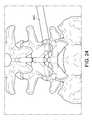
- FIG. 16is a perspective view of one aspect of a percutaneous arthrodesis method, showing the step of positioning a nerve monitoring probe with a transfer sleeve through Kambin's triangle;
- FIG. 17is a perspective view of the method of FIG. 16 , showing the step of advancing the transfer sleeve to contact a portion of the annulus for removal of the probe;
- FIG. 18is a perspective view of the method of FIG. 16 , showing the step of removing the nerve monitoring probe, leaving the transfer sleeve in place;
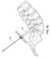
- FIG. 19is a perspective view of the method of FIG. 16 , showing the step of inserting a guide wire through the transfer sleeve to maintain a path to the disc space;
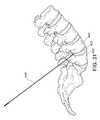
- FIG. 20is a perspective view of the method of FIG. 16 , showing the step of removing the transfer sleeve and leaving the guide wire in place;
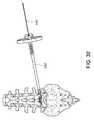
- FIG. 21is a perspective view of the method of FIG. 16 , showing the step of advancing a dilator over the guide wire;
- FIG. 22is a partially transparent perspective view of the method of FIG. 16 , showing the step of pushing a dilator into the disc space to distract the vertebral bodies;
- FIG. 23is a partially transparent perspective view of the method of FIG. 16 , showing the step of positioning an access portal into the disc space;
- FIG. 24is a partially transparent perspective view of the method of FIG. 16 , showing the step of removing the dilator and the guide wire, leaving the access portal in place;
- FIG. 25is a partially transparent perspective view of the method of FIG. 16 , showing the step of performing a discectomy and decorticating the vertebral endplates by first drilling to access the nucleus;
- FIG. 26is a partially transparent perspective view of the method of FIG. 16 , showing the step of performing a discectomy and decorticating the vertebral endplates by rotating a disc shaper;
- FIG. 27is a partially transparent perspective view of the method of FIG. 16 , showing the step of performing a discectomy and decorticating the vertebral endplates by grasping disc material with a Pituitary rongeur;
- FIG. 28is a partially transparent perspective view of the method of FIG. 16 , showing the step of performing a discectomy and decorticating the vertebral endplates by using a disc cutter;
- FIG. 29is a partially transparent perspective view of the method of FIG. 16 , showing the step of introducing a bone graft through a portal using a tube and plunger system;
- FIG. 30is a partially transparent perspective view of the method of FIG. 16 , showing the step of re-introducing a guide wire through the access portal;
- FIG. 31is a perspective view of the method of FIG. 16 , showing the removal of the access portal, leaving the guide wire in place;
- FIG. 32is a partially transparent perspective view of the method of FIG. 16 , showing the step of using the guide wire for insertion of a trial implant;
- FIG. 33is a partially transparent perspective view of the method of FIG. 16 , showing the step of connecting the implant to the insertion tool and following the guide wire to insert implant;
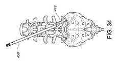
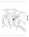
- FIG. 34is a perspective view of the method of FIG. 16 , showing the step of using the dilator to locate a path to the appropriate facet joint;
- FIG. 35is a partially transparent perspective view of the method of FIG. 16 , showing the step of using a dilator as a guide for introducing the guide wire to a depth just beyond the anticipated depth of the facet screw;
- FIG. 36is a partially transparent perspective view of the method of FIG. 16 , showing the step of introducing an access portal over the dilator for facet arthrodesis;
- FIG. 37is a partially transparent perspective view of the method of FIG. 16 , showing the step of introducing a drill via the portal to drill through a portion of the facet joint to prepare for insertion of a facet screw;
- FIG. 38is a partially transparent perspective view of the method of FIG. 16 , showing the step of introduction of the facet screws.
- FIG. 39is a partially transparent perspective view of the method of FIG. 16 , showing one aspect of a facet screw in place.
- Rangescan be expressed herein as from “about” one particular value, and/or to “about” another particular value. When such a range is expressed, another aspect includes from the one particular value and/or to the other particular value. Similarly, when values are expressed as approximations, by use of the antecedent “about,” it will be understood that the particular value forms another aspect. It will be further understood that the endpoints of each of the ranges are significant both in relation to the other endpoint, and independently of the other endpoint.
- the terms “optional” or “optionally”mean that the subsequently described event or circumstance may or may not occur, and that the description includes instances where said event or circumstance occurs and instances where it does not.
- the systemcomprises an elongated spinal implant 100 having a square or rectangular profile defined by the overall height and width.
- the implant 100that, in one aspect, defines at least one implant aperture 110 .
- the implant 100is sized for insertion between two adjacent vertebrae.
- the system 10also comprises an elongate cannulated insertion tool 200 defining an interior insertion tool pathway 210 .
- the insertion tool 200is configured to position the implant into the desired position between two spinal vertebrae.
- the distal end 202 of the elongate cannulated insertion toolmatingly engages at least a portion of at least one external surface of the implant.
- the insertion tool 200in one aspect, has an elongate lockshaft 300 positioned therein the insertion tool pathway 210 and defining a longitudinal interior lockshaft pathway 310 , wherein a distal end 302 of the elongate lockshaft 300 selectively engages a portion of the implant.
- the interior lockshaft pathway 310 and the implant aperture 110are substantially coaxial.
- the implant aperturecan extend therethrough the implant, but does not necessarily do so. In this aspect, however, the implant aperture and the interior lockshaft pathway are configured for the acceptance of a guide wire.
- the lockshaft 300can be configured to engage the implant 100 in order to maintain rotational alignment of the implant with respect to the insertion tool.
- rotation of the elongate cannulated insertion toolwould, in turn, rotate the implant along its longitudinal axis I L .
- at least a proximal portion of the implant aperturecomprises internal threads 120 and at least a portion of the distal end of the elongate lockshaft comprises external threads 320 that mate with the internal threads 120 of the implant aperture 110 .
- a handle 220can be positioned in a proximal portion 204 of the elongate cannulated insertion tool 200 .
- the handle 220provides visual means to determine the rotational orientation of the implant 100 .
- the cannulated insertion toolcan comprise markings or etchings along the length of the shaft.
- the handlealso provides the practitioner with an easy means with which to turn the implant after insertion.
- the elongate lockshaft 300can engage the implant for insertion and positioning.
- the implantcan be drawn into tighter engagement with the elongate cannulated insertion tool.
- the proximal end 204 of the elongate cannulated insertion toolcomprises internal threads 230 and at least a portion of a proximal end 304 of the elongate lockshaft 300 comprises external threads 325 that mate with the internal threads 230 of the cannulated insertion tool 200 .
- rotation of the lockshaft in a clockwise directionmoves the lockshaft longitudinally within the cannulated insertion tool in a first direction
- rotation of the lockshaft in a counterclockwise directionmoves the lockshaft 300 longitudinally within the cannulated insertion tool in a second, opposed direction.
- a knob 340is positioned on a portion of the proximal end 304 of the lockshaft to enable the rotation of the lockshaft about its longitudinal axis L L .
- Other methods of translating the lockshaft longitudinally within the cannulated insertedare also contemplated.
- the distal end 202 of the elongate cannulated insertion toolis configured to mate with at least a portion of the proximal end 104 of the implant so that they remain in rotational alignment.
- the distal end 202is saddle-shaped, where portions of the implant fit in the seat of the saddle, as illustrated in FIG. 12 .
- the implanthas a distal end and a proximal end and opposing sides or walls extending therebetween to support the adjacent vertebrae on opposing upper and lower surfaces relative to the height of the implant.
- the implantcomprises a substantially bullet shaped distal end 102 and a longitudinal axis I.sub.L substantially coaxial with the implant aperture.
- Bullet shapedcan mean that the distal end 102 is an elliptical parabaloid, conical, or the like. Such shapes enable the implant to displace the exiting nerve root in an atraumatic fashion.
- the proximal end 104 of the implant 100can be shaped matingly.
- the proximal end of the implantcan comprise a convex cylindrical surface
- the distal end 202 of the elongate cannulated insertion tool 200can comprise a correspondingly concave cylindrical surface.
- Other mating surfacesare also contemplated.
- the implantcan also have two opposing longitudinal gripping facets 130 each defining a ridged surface 132 .
- the ridged surfacesare meant to assist with the implant's ability to grip the adjacent bone structure.
- the ridges 132are angled rearwardly in order to assist in preventing the implant 100 from backing out.
- the implantfurther defines an implant cavity 140 in communication with the implant aperture 110 and substantially open to at least one, or both, of the gripping facets 130 .
- bone graft material or bone cementcan be introduced into the implant cavity 140 .
- the bone graft materialcan be, for example, autologous bone, allograft bone, bone substitute, osteoinductive agents, and the like.
- the implantitself comprises a biocompatible material, capable of being inserted into the body.
- the bio-compatible materialis selected from the group consisting of PolyEtherEtherKetone, ceramic, allograft bone, and PolyEtherEtherKetone with BaSO 4 .
- Other biocompatible materialsare also contemplated.
- the methodcomprises making a posterolateral incision to access the desired spinal motion segment; determining a target level of the disc space 402 between adjacent vertebral bodies 400 for implantation of an implant; locating a path to the disc space at the target level; inserting a guide wire 440 to maintain a path to the disc space 402 ; sliding the spinal implant along the guide wire 440 to position it into the disc space at the desired position; removing the guide wire; and fixating at least a portion of the desired spinal motion segment.
- This first stepcomprises making a posterolateral incision to access the desired spinal motion segment.
- the initial access pointcan be made through Kambin's Triangle 410 .
- Kambin's Triangleas those skilled in the art will appreciate, is the site of surgical access for posterolateral endoscopic discectomy. It is defined as a right triangle over the dorsolateral disc. The hypotenuse is the exiting nerve, the base (width) is the superior border of the caudal vertebra, and the height is the traversing nerve root.
- the methodalso comprises determining the target level of the disc space between adjacent vertebral bodies 400 . Once the target level is established, the method comprises locating a path to the disc space at the target level. This can be accomplished, for example, using a nerve monitoring probe 420 with a transfer sleeve 430 .
- the nerve monitoring probecan measure the proximity of the exiting nerve root. Once measured, in an exemplified aspect, the probe 420 can then be removed, leaving the transfer sleeve 430 in place.
- the nerve monitoring probecomprises an EMG Navigation system, comprising a blunt-tipped monopolar probe and an exchange cannula.
- the methodalso comprises inserting a guide wire through the transfer sleeve to maintain a path to the disc space.
- the guide wire 440can be a Kirschner wire or k-wire.
- one aspect of the methodcomprises removing the transfer sleeve and placing a dilator 450 over the guide wire. The dilator 450 can be driven into the disc space 402 to distract the vertebral bodies 400 .
- the next stepcomprises positioning an access portal 460 into the disc space.
- the surgeoncan slide the access portal 460 over the dilator and use an impact sleeve with a mallet to lodge the portal into the disc space.
- the dilator and guide wirecan then be removed, leaving the access portal in place.
- the methodcan comprise performing a discectomy and decorticating the vertebral endplates.
- a drill 470can be used to access the nucleus and prepare the area for other discectomy instruments.
- a disc shaper 480as shown in FIG. 26 , can be used for endplate preparation. The surgeon may elect to remove some of the loose disc material at this point.
- a pituitary rongeur 490can be used.
- a disc cutter 500as shown in FIG. 28 , can be used to accomplish a thorough discectomy. Afterwhich, the pituitary rongeur 490 can be used again to remove remaining disc remnants.
- a bone graft(not shown) can then to be introduced. As one skilled in the art can appreciate, this can be accomplished through the portal using a tube and plunger 510 system.
- the bone graftis a sentinel bone graft. The surgeon can then re-introduce the guide wire 440 and remove the access portal 460 .
- the next stepcan comprise determining the height of an adjacent level healthy disc to assist with the selection of an appropriately sized implant.
- the size of the implant 100can be confirmed with a paddle trial or a solid body trial. To do so, the surgeon can first insert the trial implant along a path, guided by the guide wire. An insertion tool 200 , as described herein above, may be used. Once inserted, if the selected trial implant cannot be rotated into an erect position, the surgeon can then step down to a smaller size. Alternately, if the selected trail can be rotated into an erect position without much frictional resistance, the surgeon can choose the next larger size. Several iterations may be necessary to achieve the correctly sized implant. As shown in FIGS.
- the implant 100has an elongated body, the body having a length extending from a distal end to a proximal end. The length is greater than the height or the width of the body of the implant 100 .
- the bodyhas opposing sides or walls extending therebetween the proximal and distal ends to support the adjacent vertebrae on opposing upper and lower surfaces.
- the substantially square or rectangular cross section midway from the two ends 102 , 104as seen in FIGS. 7 and 10 and also in FIGS. 12 and 15 respectively.
- the proper height to width ratiois in a range of 1:1 to 2:1 as illustrated.
- the resultant selected height of the implant 100is based on the height of an adjacent level healthy disc. As noted above, the height of the implant 100 replicates the healthy disc height.
- the inserted implantwhen fully inserted, tenses the soft tissue without damaging the nerves while reestablishing the normal disc height of the vertebral bodies.
- the implant 100comprises an implant cavity 140 .
- the methodcomprises, after determining the appropriate implant height and length from the trials, loading graft material into the implant cavity and connecting the implant to the insertion tool and following the guide wire to insert the implant.
- Imaging technologycan be used to verify the correct location of the implant.
- fluorographic imagingcan be used to watch radiographic markers in order to determine the correct location of the implant.
- the implantis placed properly. Once the implant is placed properly, the surgeon can then turn the implant 90 degrees and release it from the insertion tool 200 .
- the next step of the methodcomprises fixating at least a portion of the desired spinal motion segment.
- thiscomprises fixating a portion of the facet of the desired disc with a facet screw 520 .
- the facet screwcan be a Spartan Facet Screw.
- the surgeoncan make an incision substantially proximate the spinous process of L3.
- the methodcomprises using the dilator 450 to locate a path to the appropriate inferior articular process.
- the dilatoris used as a guide for introducing the guide wire.
- the guide wireis delivered by using an electric drill, which delivers the guide wire to a depth just beyond the anticipated depth of the facet screw.
- Alternate fixation methodsinclude, but are not limited to, pedicle screws, spinous process clamps, and other known fixation methods.
- the methodalso comprises further attaching a neural monitoring lead to the guide wire 440 and stimulating it to a level up to 10 mA to detect the proximity to the exiting nerve roots and cauda equina.
- a neural monitoring leadto the guide wire 440 and stimulating it to a level up to 10 mA to detect the proximity to the exiting nerve roots and cauda equina.
- the surgeoncan place guide wires for all of the facet screws. The dilators could then be removed, leaving the guide wires in place.
- the next step in the methodcomprises performing facet arthrodesis by using a rasp (not shown) capable of removing cartilage, decorticating the joint surfaces.
- a rasp(not shown) capable of removing cartilage, decorticating the joint surfaces.
- an Amendia Spear disposable raspmay be used.
- the raspcan comprise a substantially Y-shaped distal end to conform to a portion of the positioned guide wire and move thereabout the guide wire 440 .
- the methodcomprises using the same incision as with the interbody approach, and inserting a dilator 450 to target the lateral aspect of the facet joint 412 .
- An access portalis, then, introduced over the dilator. Once the portal is positioned, the dilator may be removed.
- the appropriate sized raspcan be introduced via the portal 460 to remove cartilage and to decorticate the joint surfaces.
- the surgeoncan, next, load a graft into the delivery tube and insert it into the prepared facet joint 412 .
- this processis repeated through a new incision in a similar location on the contralateral side, targeting the contralateral facet.
- the next step of the methodcomprises fixating the facet screws.
- the facet screwsmay comprise a Spartan Facet Screw.
- the surgeonwill re-insert dilators over each of the guide wires. Then, access portals will be introduced via each of the dilators. The dilators can then be removed, leaving the guide wires in place. The surgeon will then deliver the drill bit 470 over the guide wire, penetrating the superior articular process of the inferior vertebral body and drill into the pedicle of the inferior vertebral body.
- the facet screwscan, then, be introduced, for example, with a screw retaining driver.
- the methodcan comprise driving a lag screw to a desired depth to compress the facet joint onto the graft.
- a facet screw with threads along the full lengthmay be used to immobilize the facet joint.
- the retaining drivercan be released from the implanted screw and the steps of this aspect can be repeated for all levels, bilaterally.
- the methodfurther comprises performing a foramen nerve root or central decompression, if the surgeon determines that this step is required.
Landscapes
- Health & Medical Sciences (AREA)
- Orthopedic Medicine & Surgery (AREA)
- Engineering & Computer Science (AREA)
- Biomedical Technology (AREA)
- Life Sciences & Earth Sciences (AREA)
- Neurology (AREA)
- Animal Behavior & Ethology (AREA)
- Veterinary Medicine (AREA)
- Heart & Thoracic Surgery (AREA)
- Public Health (AREA)
- General Health & Medical Sciences (AREA)
- Transplantation (AREA)
- Surgery (AREA)
- Oral & Maxillofacial Surgery (AREA)
- Cardiology (AREA)
- Vascular Medicine (AREA)
- Molecular Biology (AREA)
- Medical Informatics (AREA)
- Nuclear Medicine, Radiotherapy & Molecular Imaging (AREA)
- Physical Education & Sports Medicine (AREA)
- Dentistry (AREA)
- Prostheses (AREA)
- Surgical Instruments (AREA)
Abstract
Description
Claims (13)
Priority Applications (16)
| Application Number | Priority Date | Filing Date | Title |
|---|---|---|---|
| US13/028,310US9265622B2 (en) | 2010-03-22 | 2011-02-16 | Percutaneous arthrodesis method and system |
| JP2013554438AJP2014512883A (en) | 2011-02-16 | 2011-11-01 | Percutaneous joint fixation method and system |
| CA2827201ACA2827201C (en) | 2011-02-16 | 2011-11-01 | Percutaneous arthrodesis method and system |
| AU2011359385AAU2011359385A1 (en) | 2011-02-16 | 2011-11-01 | Percutaneous arthrodesis method and system |
| CN201180070148.7ACN103501733A (en) | 2011-02-16 | 2011-11-01 | Percutaneous arthrodesis method and system |
| KR1020137024425AKR20140023900A (en) | 2011-02-16 | 2011-11-01 | Percutaneous arthrodesis method and system |
| PCT/US2011/058737WO2012112196A1 (en) | 2011-02-16 | 2011-11-01 | Percutaneous arthrodesis method and system |
| BR112013021002ABR112013021002A2 (en) | 2011-02-16 | 2011-11-01 | percutaneous arthrodesis method and system |
| MX2013009493AMX350827B (en) | 2011-02-16 | 2011-11-01 | Percutaneous arthrodesis method and system. |
| EP11858728.6AEP2675400B1 (en) | 2011-02-16 | 2011-11-01 | Percutaneous arthrodesis system |
| MX2016004388AMX387922B (en) | 2011-02-16 | 2011-11-01 | METHOD AND SYSTEM OF PERCUTANEOUS ARTHRODESIS. |
| US13/294,544US8496709B2 (en) | 2010-03-22 | 2011-11-11 | Spinal Implant |
| US14/191,969US9226835B2 (en) | 2010-03-22 | 2014-02-27 | Percutaneous arthrodesis method and system |
| US14/242,310US9566170B2 (en) | 2010-03-22 | 2014-04-01 | Percutaneous arthrodesis method and system |
| US14/242,348US9107768B2 (en) | 2010-03-22 | 2014-04-01 | Percutaneous arthrodesis method and system |
| AU2016222305AAU2016222305A1 (en) | 2011-02-16 | 2016-08-29 | Percutaneous arthrodesis method and system |
Applications Claiming Priority (2)
| Application Number | Priority Date | Filing Date | Title |
|---|---|---|---|
| US31606910P | 2010-03-22 | 2010-03-22 | |
| US13/028,310US9265622B2 (en) | 2010-03-22 | 2011-02-16 | Percutaneous arthrodesis method and system |
Related Child Applications (4)
| Application Number | Title | Priority Date | Filing Date |
|---|---|---|---|
| US13/294,544ContinuationUS8496709B2 (en) | 2010-03-22 | 2011-11-11 | Spinal Implant |
| US14/191,969DivisionUS9226835B2 (en) | 2010-03-22 | 2014-02-27 | Percutaneous arthrodesis method and system |
| US14/242,348ContinuationUS9107768B2 (en) | 2010-03-22 | 2014-04-01 | Percutaneous arthrodesis method and system |
| US14/242,310ContinuationUS9566170B2 (en) | 2010-03-22 | 2014-04-01 | Percutaneous arthrodesis method and system |
Publications (2)
| Publication Number | Publication Date |
|---|---|
| US20110230965A1 US20110230965A1 (en) | 2011-09-22 |
| US9265622B2true US9265622B2 (en) | 2016-02-23 |
Family
ID=46673227
Family Applications (4)
| Application Number | Title | Priority Date | Filing Date |
|---|---|---|---|
| US13/028,310Active2033-06-30US9265622B2 (en) | 2010-03-22 | 2011-02-16 | Percutaneous arthrodesis method and system |
| US14/191,969Active2031-04-23US9226835B2 (en) | 2010-03-22 | 2014-02-27 | Percutaneous arthrodesis method and system |
| US14/242,310ActiveUS9566170B2 (en) | 2010-03-22 | 2014-04-01 | Percutaneous arthrodesis method and system |
| US14/242,348Active2031-03-13US9107768B2 (en) | 2010-03-22 | 2014-04-01 | Percutaneous arthrodesis method and system |
Family Applications After (3)
| Application Number | Title | Priority Date | Filing Date |
|---|---|---|---|
| US14/191,969Active2031-04-23US9226835B2 (en) | 2010-03-22 | 2014-02-27 | Percutaneous arthrodesis method and system |
| US14/242,310ActiveUS9566170B2 (en) | 2010-03-22 | 2014-04-01 | Percutaneous arthrodesis method and system |
| US14/242,348Active2031-03-13US9107768B2 (en) | 2010-03-22 | 2014-04-01 | Percutaneous arthrodesis method and system |
Country Status (10)
| Country | Link |
|---|---|
| US (4) | US9265622B2 (en) |
| EP (1) | EP2675400B1 (en) |
| JP (1) | JP2014512883A (en) |
| KR (1) | KR20140023900A (en) |
| CN (1) | CN103501733A (en) |
| AU (2) | AU2011359385A1 (en) |
| BR (1) | BR112013021002A2 (en) |
| CA (1) | CA2827201C (en) |
| MX (2) | MX387922B (en) |
| WO (1) | WO2012112196A1 (en) |
Cited By (7)
| Publication number | Priority date | Publication date | Assignee | Title |
|---|---|---|---|---|
| US20190008527A1 (en)* | 2013-03-11 | 2019-01-10 | DePuy Synthes Products, Inc. | Method and apparatus for minimally invasive insertion of intervertebral implants |
| USD847339S1 (en) | 2017-06-26 | 2019-04-30 | Advanced Research System, LLC | Spinal fusion cage |
| USD879295S1 (en) | 2017-02-13 | 2020-03-24 | Advance Research System, Llc | Spinal fusion cage |
| US11058551B2 (en) | 2016-12-16 | 2021-07-13 | Advance Research System, Llc | Interbody implant with concave profiled nose |
| US11628070B2 (en)* | 2018-02-26 | 2023-04-18 | Neo Medical Sa | Spine cage holder |
| US11737888B1 (en) | 2019-09-19 | 2023-08-29 | Advance Research System, Llc | Spinal fusion implant system and method |
| US12433762B2 (en) | 2022-12-01 | 2025-10-07 | Percheron Spine, Llc | Spinal implant and delivery system |
Families Citing this family (62)
| Publication number | Priority date | Publication date | Assignee | Title |
|---|---|---|---|---|
| US20120143341A1 (en)* | 2006-12-12 | 2012-06-07 | Arthrodisc, L.L.C. | Devices and methods for visual differentiation of intervertebral spaces |
| EP2547292B1 (en) | 2010-03-16 | 2019-04-24 | Pinnacle Spine Group, LLC | Ntervertebral implants and graft delivery systems |
| US8523873B2 (en)* | 2010-04-08 | 2013-09-03 | Warsaw Orthopedic, Inc. | Neural-monitoring enabled sleeves for surgical instruments |
| US8858637B2 (en) | 2010-09-30 | 2014-10-14 | Stryker Spine | Surgical implant with guiding rail |
| US9468535B2 (en)* | 2010-12-17 | 2016-10-18 | K2M, Inc. | Interbody spacer |
| US8394129B2 (en) | 2011-03-10 | 2013-03-12 | Interventional Spine, Inc. | Method and apparatus for minimally invasive insertion of intervertebral implants |
| US8518087B2 (en) | 2011-03-10 | 2013-08-27 | Interventional Spine, Inc. | Method and apparatus for minimally invasive insertion of intervertebral implants |
| US8790406B1 (en)* | 2011-04-01 | 2014-07-29 | William D. Smith | Systems and methods for performing spine surgery |
| US9380932B1 (en) | 2011-11-02 | 2016-07-05 | Pinnacle Spine Group, Llc | Retractor devices for minimally invasive access to the spine |
| US20130150970A1 (en)* | 2011-11-21 | 2013-06-13 | Basix Spine Llc | Implant with Sensor |
| US9463052B2 (en) | 2012-01-12 | 2016-10-11 | Integrity Implants Inc. | Access assembly for anterior and lateral spinal procedures |
| US8512409B1 (en)* | 2012-02-10 | 2013-08-20 | Integral Spine Solutions, Inc. | Implant with outwardly extending fixation elements |
| US8936626B1 (en) | 2012-02-17 | 2015-01-20 | Nuvasive, Inc. | Bi-cortical screw fixation |
| US9393126B2 (en)* | 2012-04-20 | 2016-07-19 | Peter L. Mayer | Bilaterally placed disc prosthesis for spinal implant and method of bilateral placement |
| US9364339B2 (en) | 2012-04-30 | 2016-06-14 | Peter L. Mayer | Unilaterally placed expansile spinal prosthesis |
| US9278011B2 (en)* | 2012-08-08 | 2016-03-08 | Spectrum Spine Ip Holdings, Llc | Percutaneous cage delivery systems devices and methods |
| US20140067069A1 (en) | 2012-08-30 | 2014-03-06 | Interventional Spine, Inc. | Artificial disc |
| US9445918B1 (en) | 2012-10-22 | 2016-09-20 | Nuvasive, Inc. | Expandable spinal fusion implants and related instruments and methods |
| US9993353B2 (en) | 2013-03-14 | 2018-06-12 | DePuy Synthes Products, Inc. | Method and apparatus for minimally invasive insertion of intervertebral implants |
| US9480574B2 (en) | 2013-03-14 | 2016-11-01 | Benvenue Medical, Inc. | Spinal fusion implants and devices and methods for deploying such implants |
| WO2014159739A1 (en) | 2013-03-14 | 2014-10-02 | Pinnacle Spine Group, Llc | Interbody implants and graft delivery systems |
| US20140276591A1 (en)* | 2013-03-14 | 2014-09-18 | Mi4Spine, Llc | Percutaneous intervertebral annular regeneration |
| FR3006170B1 (en)* | 2013-05-31 | 2015-06-26 | Osd Orthopaedic & Spine Dev | INTERSOMATIC PROSTHESIS PRODUCING INDIVIDUALIZED LORDOSE SETTING |
| EP3068316B1 (en) | 2013-11-13 | 2019-08-07 | Thixos LLC | Devices and kits for treatment of facet joints |
| US9642720B2 (en) | 2013-12-19 | 2017-05-09 | Amendia, Inc. | Expandable spinal implant |
| US9931219B2 (en)* | 2014-03-07 | 2018-04-03 | Arthrosurface Incorporated | Implant and anchor assembly |
| US9498351B2 (en)* | 2014-06-04 | 2016-11-22 | Spine Wave, Inc. | Apparatus for locating the position of a spinal implant during surgery |
| US10314605B2 (en) | 2014-07-08 | 2019-06-11 | Benvenue Medical, Inc. | Apparatus and methods for disrupting intervertebral disc tissue |
| US10022243B2 (en) | 2015-02-06 | 2018-07-17 | Benvenue Medical, Inc. | Graft material injector system and method |
| US20180049754A1 (en)* | 2015-03-13 | 2018-02-22 | Redemed S.R.L. | Intervertebral prosthesis, apparatus for implanting intervertebral prostheses and surgical method for implanting intervertebral prostheses, particularly for percutaneous mini-invasive surgery procedures |
| US9833338B2 (en)* | 2015-06-30 | 2017-12-05 | Expanding Orthopedics Inc. | Tool for intervertebral cage |
| US11439380B2 (en) | 2015-09-04 | 2022-09-13 | Medos International Sarl | Surgical instrument connectors and related methods |
| US12150636B2 (en) | 2015-09-04 | 2024-11-26 | Medos International Sárl | Surgical instrument connectors and related methods |
| US10987129B2 (en) | 2015-09-04 | 2021-04-27 | Medos International Sarl | Multi-shield spinal access system |
| US11672562B2 (en) | 2015-09-04 | 2023-06-13 | Medos International Sarl | Multi-shield spinal access system |
| US11744447B2 (en) | 2015-09-04 | 2023-09-05 | Medos International | Surgical visualization systems and related methods |
| CN113143355A (en) | 2015-09-04 | 2021-07-23 | 美多斯国际有限公司 | Multi-shield spinal access system |
| US10058350B2 (en) | 2015-09-24 | 2018-08-28 | Integrity Implants, Inc. | Access assembly for anterior and lateral spinal procedures |
| FR3047657B1 (en)* | 2016-02-15 | 2018-02-09 | Backbone | INTERVERTEBRAL IMPLANT OF DYNAMIC STABILIZATION AND SURGICAL KIT INCORPORATING IT |
| US10368881B2 (en) | 2016-06-03 | 2019-08-06 | Quandary Medical, Llc | Method and apparatus for minimally invasive posterolateral spinal fusion |
| IT201600105751A1 (en) | 2016-10-20 | 2018-04-20 | Medacta Int Sa | INTERVERTEBRAL FUSION CAGE |
| CN106806041A (en)* | 2017-02-14 | 2017-06-09 | 武汉医佳宝生物材料有限公司 | A kind of Invasive lumbar fusion device erector |
| US10758286B2 (en) | 2017-03-22 | 2020-09-01 | Benvenue Medical, Inc. | Minimal impact access system to disc space |
| CN107212911B (en)* | 2017-06-30 | 2023-12-15 | 李恰 | Rotary cutter for intervertebral disc operation |
| USD831828S1 (en)* | 2017-07-12 | 2018-10-23 | NuTech Spine, Inc. | Spinal implant |
| FR3068877B1 (en)* | 2017-07-17 | 2021-07-09 | Sc Medica | IMPLANT DEVICE FOR THE PERFORMANCE OF A POSTERIOR SPINAL ARTHRODESIS AT THE LEVEL OF A FACETARY JOINT |
| WO2019148083A1 (en) | 2018-01-29 | 2019-08-01 | Benvenue Medical, Inc. | Minimally invasive interbody fusion |
| WO2019178575A1 (en) | 2018-03-16 | 2019-09-19 | Benvenue Medical, Inc. | Articulated instrumentation and methods of using the same |
| ES2981770T3 (en)* | 2019-03-05 | 2024-10-10 | Medacta Int Sa | Holding and positioning tool for a spinal polyaxial screw insertion guide |
| EP3711687B1 (en)* | 2019-03-19 | 2023-01-11 | BioTissue SA | Set for endoscopic fixing of an implant in an intervertebral disc with a nail or pin |
| CN111035430B (en)* | 2019-03-26 | 2025-01-07 | 温州医科大学附属第二医院、温州医科大学附属育英儿童医院 | A real-time bone removal trephine with scale visualization for spinal endoscopy |
| US11712188B2 (en) | 2019-05-07 | 2023-08-01 | Medtronic, Inc. | Posterior left bundle branch engagement |
| US11583408B2 (en)* | 2019-05-18 | 2023-02-21 | Anjali Investments Llc | Minimally invasive posterior cervical facet arthrodesis shim implant and tools therefor |
| KR102208305B1 (en)* | 2020-06-17 | 2021-01-27 | 주식회사 텍코드 | Interbody Fusion cage operation system |
| KR102365883B1 (en)* | 2020-07-07 | 2022-02-23 | 김현성 | Artificial disc insert guide device for spinal endoscopic surgery |
| EP4203812B1 (en)* | 2020-08-28 | 2024-10-09 | Nuvasive, Inc. | Ratchet retracting handles |
| US12329423B2 (en)* | 2020-12-21 | 2025-06-17 | Nuvasive Inc. | Stylet control handles and methods of using the same |
| US11534309B1 (en)* | 2021-07-20 | 2022-12-27 | Globus Medical Inc. | Interlaminar lumbar interbody fusion implants, intradiscal implants, instruments, and methods |
| KR102599638B1 (en)* | 2021-08-24 | 2023-11-07 | (주)스파인닥터스 | Spine insert and an medical instrument for implanting an spine insert |
| FR3132625B1 (en) | 2022-02-17 | 2024-04-12 | Sc Medica | IMPLANT DEVICE FOR PERFORMING A POSTERIOR SPINAL ARTHRODESIS AT THE LEVEL OF A FACET JOINT, AND SYSTEM COMPRISING SAID IMPLANT AND ITS PLACEMENT TOOL. |
| US11849975B1 (en)* | 2022-11-09 | 2023-12-26 | Spinal Simplicity, Llc | Methods for single incision anterior and posterior spinal fusion procedure |
| WO2025158455A1 (en)* | 2024-01-24 | 2025-07-31 | Shah Nisarg Pankaj | Stand alone unilateral biportal endoscopy cage |
Citations (10)
| Publication number | Priority date | Publication date | Assignee | Title |
|---|---|---|---|---|
| US6371988B1 (en)* | 1996-10-23 | 2002-04-16 | Sdgi Holdings, Inc. | Bone grafts |
| US20040127990A1 (en)* | 2002-12-31 | 2004-07-01 | Bartish, Charles M. | Novel banana cage |
| US20060276902A1 (en)* | 2005-06-03 | 2006-12-07 | Zipnick Richard I | Minimally invasive apparatus to manipulate and revitalize spinal column disc |
| US20060293748A1 (en)* | 2005-06-24 | 2006-12-28 | Spineworks, Llc | Prosthetic implant, and a method and tool for the insertion of same |
| US20070162046A1 (en)* | 2004-01-29 | 2007-07-12 | Vandewalle Mark V | Method and apparatus for retaining a guide wire |
| US20070173954A1 (en)* | 2005-08-22 | 2007-07-26 | Vilex, Inc. | Subtalar implant and methods of use thereof |
| US7311734B2 (en)* | 1995-10-16 | 2007-12-25 | Warsaw Orthopedic, Inc. | Intervertebral spacers |
| US20080262623A1 (en)* | 2005-05-06 | 2008-10-23 | Titan Spine, Llc | Composite interbody spinal implant having openings of predetermined size and shape |
| US20090138015A1 (en)* | 2007-11-19 | 2009-05-28 | Magellan Spine Technologies, Inc. | Spinal implants and methods |
| US20110112587A1 (en)* | 2009-11-11 | 2011-05-12 | Nirali Patel | Instrument for insertion and deployment of features on an implant |
Family Cites Families (27)
| Publication number | Priority date | Publication date | Assignee | Title |
|---|---|---|---|---|
| DE20004692U1 (en)* | 2000-03-14 | 2001-07-26 | Sofamor Danek GmbH, 94469 Deggendorf | Vertebral implant for screwing into an intervertebral space |
| US5484437A (en)* | 1988-06-13 | 1996-01-16 | Michelson; Gary K. | Apparatus and method of inserting spinal implants |
| CA1333209C (en)* | 1988-06-28 | 1994-11-29 | Gary Karlin Michelson | Artificial spinal fusion implants |
| BE1007549A3 (en)* | 1993-09-21 | 1995-08-01 | Beckers Louis Francois Charles | Implant. |
| ES2236792T3 (en)* | 1995-03-27 | 2005-07-16 | Sdgi Holdings, Inc. | IMPLANTS OF SPINAL FUSION AND INSTRUMENTS FOR INSERTION AND REVIEW. |
| CA2199462C (en)* | 1996-03-14 | 2006-01-03 | Charles J. Winslow | Method and instrumentation for implant insertion |
| EP1221914B1 (en)* | 1999-10-19 | 2003-09-03 | SDGI Holdings, Inc. | Cutting tool preparation accessory for mounting the implant |
| US7056321B2 (en)* | 2000-08-01 | 2006-06-06 | Endius, Incorporated | Method of securing vertebrae |
| US7238203B2 (en)* | 2001-12-12 | 2007-07-03 | Vita Special Purpose Corporation | Bioactive spinal implants and method of manufacture thereof |
| US7582058B1 (en)* | 2002-06-26 | 2009-09-01 | Nuvasive, Inc. | Surgical access system and related methods |
| US7556651B2 (en)* | 2004-01-09 | 2009-07-07 | Warsaw Orthopedic, Inc. | Posterior spinal device and method |
| EP1713408B1 (en)* | 2004-02-09 | 2010-09-15 | DePuy Spine, Inc. | Systems for spinal surgery |
| US7651496B2 (en)* | 2004-07-23 | 2010-01-26 | Zimmer Spine, Inc. | Methods and apparatuses for percutaneous implant delivery |
| US7651502B2 (en)* | 2004-09-24 | 2010-01-26 | Jackson Roger P | Spinal fixation tool set and method for rod reduction and fastener insertion |
| US7857832B2 (en)* | 2004-12-08 | 2010-12-28 | Interventional Spine, Inc. | Method and apparatus for spinal stabilization |
| US7909872B2 (en) | 2005-06-03 | 2011-03-22 | Zipnick Richard I | Minimally invasive apparatus to manipulate and revitalize spinal column disc |
| US8083773B2 (en)* | 2005-07-15 | 2011-12-27 | Muhammad Abubakar Atiq Durrani | Apparatus for minimally invasive posterior correction of spinal deformity |
| US20070244562A1 (en)* | 2005-08-26 | 2007-10-18 | Magellan Spine Technologies, Inc. | Spinal implants and methods of providing dynamic stability to the spine |
| EP2023811B1 (en)* | 2006-05-17 | 2018-08-08 | NuVasive, Inc. | Surgical trajectory monitoring system |
| EP2114257B1 (en)* | 2007-02-09 | 2013-05-22 | Alphatec Spine, Inc. | Curvilinear spinal access device |
| EP2208481B1 (en)* | 2007-07-27 | 2016-12-28 | R Tree Innovations, LLC | Inter-Body Implantation System |
| US8343189B2 (en)* | 2007-09-25 | 2013-01-01 | Zyga Technology, Inc. | Method and apparatus for facet joint stabilization |
| US20090299479A1 (en)* | 2007-10-19 | 2009-12-03 | Jones Robert J | Suture guided implant |
| CA2717610A1 (en)* | 2008-03-06 | 2009-09-11 | Synthes Usa, Llc | Facet interference screw |
| JP2010154993A (en)* | 2008-12-29 | 2010-07-15 | Peter Brehm Japan:Kk | Insertion and arrangement adjusting implement for intervertebral implant |
| ES2563172T3 (en)* | 2009-07-09 | 2016-03-11 | R Tree Innovations, Llc | Flexible intersomatic implant |
| US8496709B2 (en) | 2010-03-22 | 2013-07-30 | Amendia, Inc | Spinal Implant |
- 2011
- 2011-02-16USUS13/028,310patent/US9265622B2/enactiveActive
- 2011-11-01MXMX2016004388Apatent/MX387922B/enunknown
- 2011-11-01CNCN201180070148.7Apatent/CN103501733A/enactivePending
- 2011-11-01BRBR112013021002Apatent/BR112013021002A2/ennot_activeApplication Discontinuation
- 2011-11-01AUAU2011359385Apatent/AU2011359385A1/ennot_activeAbandoned
- 2011-11-01WOPCT/US2011/058737patent/WO2012112196A1/enactiveApplication Filing
- 2011-11-01KRKR1020137024425Apatent/KR20140023900A/ennot_activeCeased
- 2011-11-01CACA2827201Apatent/CA2827201C/enactiveActive
- 2011-11-01MXMX2013009493Apatent/MX350827B/enactiveIP Right Grant
- 2011-11-01EPEP11858728.6Apatent/EP2675400B1/enactiveActive
- 2011-11-01JPJP2013554438Apatent/JP2014512883A/enactivePending
- 2014
- 2014-02-27USUS14/191,969patent/US9226835B2/enactiveActive
- 2014-04-01USUS14/242,310patent/US9566170B2/enactiveActive
- 2014-04-01USUS14/242,348patent/US9107768B2/enactiveActive
- 2016
- 2016-08-29AUAU2016222305Apatent/AU2016222305A1/ennot_activeAbandoned
Patent Citations (10)
| Publication number | Priority date | Publication date | Assignee | Title |
|---|---|---|---|---|
| US7311734B2 (en)* | 1995-10-16 | 2007-12-25 | Warsaw Orthopedic, Inc. | Intervertebral spacers |
| US6371988B1 (en)* | 1996-10-23 | 2002-04-16 | Sdgi Holdings, Inc. | Bone grafts |
| US20040127990A1 (en)* | 2002-12-31 | 2004-07-01 | Bartish, Charles M. | Novel banana cage |
| US20070162046A1 (en)* | 2004-01-29 | 2007-07-12 | Vandewalle Mark V | Method and apparatus for retaining a guide wire |
| US20080262623A1 (en)* | 2005-05-06 | 2008-10-23 | Titan Spine, Llc | Composite interbody spinal implant having openings of predetermined size and shape |
| US20060276902A1 (en)* | 2005-06-03 | 2006-12-07 | Zipnick Richard I | Minimally invasive apparatus to manipulate and revitalize spinal column disc |
| US20060293748A1 (en)* | 2005-06-24 | 2006-12-28 | Spineworks, Llc | Prosthetic implant, and a method and tool for the insertion of same |
| US20070173954A1 (en)* | 2005-08-22 | 2007-07-26 | Vilex, Inc. | Subtalar implant and methods of use thereof |
| US20090138015A1 (en)* | 2007-11-19 | 2009-05-28 | Magellan Spine Technologies, Inc. | Spinal implants and methods |
| US20110112587A1 (en)* | 2009-11-11 | 2011-05-12 | Nirali Patel | Instrument for insertion and deployment of features on an implant |
Non-Patent Citations (2)
| Title |
|---|
| NonFinal Rejection issued Feb. 17, 2012, in U.S. Appl. No. 13/294,544. |
| Response to NonFinal Rejection submitted May 17, 2012 in U.S. Appl. No. 13/294,544. |
Cited By (13)
| Publication number | Priority date | Publication date | Assignee | Title |
|---|---|---|---|---|
| US20190008527A1 (en)* | 2013-03-11 | 2019-01-10 | DePuy Synthes Products, Inc. | Method and apparatus for minimally invasive insertion of intervertebral implants |
| US11759329B2 (en) | 2013-03-11 | 2023-09-19 | DePuy Synthes Products, Inc. | Method and apparatus for minimally invasive insertion of intervertebral implants |
| US10813772B2 (en) | 2013-03-11 | 2020-10-27 | DePuy Synthes Products, Inc. | Method and apparatus for minimally invasive insertion of intervertebral implants |
| US10898341B2 (en)* | 2013-03-11 | 2021-01-26 | DePuy Synthes Products, Inc. | Method and apparatus for minimally invasive insertion of intervertebral implants |
| US10918495B2 (en) | 2013-03-11 | 2021-02-16 | DePuy Synthes Products, Inc. | Method and apparatus for minimally invasive insertion of intervertebral implants |
| US11058551B2 (en) | 2016-12-16 | 2021-07-13 | Advance Research System, Llc | Interbody implant with concave profiled nose |
| USD923178S1 (en) | 2017-02-13 | 2021-06-22 | Advance Research System, Llc | Spinal fusion cage |
| USD879295S1 (en) | 2017-02-13 | 2020-03-24 | Advance Research System, Llc | Spinal fusion cage |
| USD847339S1 (en) | 2017-06-26 | 2019-04-30 | Advanced Research System, LLC | Spinal fusion cage |
| US11628070B2 (en)* | 2018-02-26 | 2023-04-18 | Neo Medical Sa | Spine cage holder |
| US12409051B2 (en)* | 2018-02-26 | 2025-09-09 | Neo Medical Sa | Spine cage holder |
| US11737888B1 (en) | 2019-09-19 | 2023-08-29 | Advance Research System, Llc | Spinal fusion implant system and method |
| US12433762B2 (en) | 2022-12-01 | 2025-10-07 | Percheron Spine, Llc | Spinal implant and delivery system |
Also Published As
| Publication number | Publication date |
|---|---|
| KR20140023900A (en) | 2014-02-27 |
| AU2016222305A1 (en) | 2016-09-22 |
| JP2014512883A (en) | 2014-05-29 |
| CA2827201C (en) | 2018-08-21 |
| BR112013021002A2 (en) | 2016-10-11 |
| US20110230965A1 (en) | 2011-09-22 |
| EP2675400A1 (en) | 2013-12-25 |
| MX387922B (en) | 2025-03-19 |
| US9226835B2 (en) | 2016-01-05 |
| US9107768B2 (en) | 2015-08-18 |
| WO2012112196A1 (en) | 2012-08-23 |
| AU2011359385A1 (en) | 2013-09-05 |
| US20140214164A1 (en) | 2014-07-31 |
| CA2827201A1 (en) | 2012-08-23 |
| US9566170B2 (en) | 2017-02-14 |
| US20140194993A1 (en) | 2014-07-10 |
| EP2675400A4 (en) | 2014-09-03 |
| MX2013009493A (en) | 2014-02-28 |
| US20140214165A1 (en) | 2014-07-31 |
| MX350827B (en) | 2017-09-22 |
| EP2675400B1 (en) | 2020-01-08 |
| CN103501733A (en) | 2014-01-08 |
Similar Documents
| Publication | Publication Date | Title |
|---|---|---|
| US9265622B2 (en) | Percutaneous arthrodesis method and system | |
| US8496709B2 (en) | Spinal Implant | |
| US11850156B2 (en) | Systems, devices, and methods for joint fusion | |
| US10736661B2 (en) | Method and apparatus for minimally invasive insertion of intervertebral implants | |
| US9649138B2 (en) | Facet screw and method for spinal stabilization | |
| US7615079B2 (en) | Monorail system | |
| US8439925B2 (en) | Transiliac-transsacral method of performing lumbar spinal interventions | |
| US20140257489A1 (en) | Method and apparatus for minimally invasive insertion of intervertebral implants | |
| US20140276851A1 (en) | Systems and methods for removing an implant | |
| US11918488B2 (en) | Minimally invasive surgery (MIS) methods and devices | |
| US20250248715A1 (en) | Systems, devices, and methods for preparing bone to receive an implant |
Legal Events
| Date | Code | Title | Description |
|---|---|---|---|
| AS | Assignment | Owner name:AMENDIA, INC., GEORGIA Free format text:ASSIGNMENT OF ASSIGNORS INTEREST;ASSIGNORS:SCHELL, GERALD, MR.;DAVENPORT, ALAN SCOTT, MR.;ANDERSON, TRACY SCOTT, MR.;AND OTHERS;SIGNING DATES FROM 20101230 TO 20110412;REEL/FRAME:026160/0774 | |
| AS | Assignment | Owner name:ATLANTIC CAPITAL BANK, GEORGIA Free format text:SECURITY AGREEMENT;ASSIGNOR:AMENDIA, INC.;REEL/FRAME:027335/0225 Effective date:20111028 | |
| AS | Assignment | Owner name:ATLANTIC CAPITAL BANK, GEORGIA Free format text:SECURITY AGREEMENT;ASSIGNOR:AMENDIA, INC.;REEL/FRAME:028141/0759 Effective date:20120430 | |
| AS | Assignment | Owner name:MEDLINE INDUSTRIES, INC., ILLINOIS Free format text:SECURITY AGREEMENT;ASSIGNOR:AMENDIA, INC.;REEL/FRAME:028148/0413 Effective date:20120501 | |
| AS | Assignment | Owner name:AMENDIA, INC., GEORGIA Free format text:RELEASE BY SECURED PARTY;ASSIGNOR:ATLANTIC CAPITAL BANK;REEL/FRAME:032663/0197 Effective date:20140409 | |
| AS | Assignment | Owner name:JP MORGAN CHASE BANK NA, TEXAS Free format text:SECURITY INTEREST;ASSIGNOR:AMENDIA, INC.;REEL/FRAME:033120/0286 Effective date:20140404 | |
| AS | Assignment | Owner name:SILICON VALLEY BANK, AS ADMINISTRATIVE AGENT, GEOR Free format text:PATENT SECURITY AGREEMENT;ASSIGNORS:AMENDIA, INC.;OMNI ACQUISITION, INC.;REEL/FRAME:033696/0940 Effective date:20140905 | |
| AS | Assignment | Owner name:AMENDIA, INC., GEORGIA Free format text:RELEASE BY SECURED PARTY;ASSIGNOR:JPMORGAN CHASE BANK, N.A.;REEL/FRAME:033771/0759 Effective date:20140908 | |
| AS | Assignment | Owner name:AMENDIA, INC., GEORGIA Free format text:RELEASE BY SECURED PARTY;ASSIGNOR:ATLANTIC CAPITAL BANK;REEL/FRAME:037652/0714 Effective date:20160202 | |
| STCF | Information on status: patent grant | Free format text:PATENTED CASE | |
| AS | Assignment | Owner name:AMENDIA, INC., GEORGIA Free format text:RELEASE BY SECURED PARTY;ASSIGNOR:SILICON VALLEY BANK, AS ADMINISTRATIVE AGENT;REEL/FRAME:038578/0828 Effective date:20160429 Owner name:OMNI ACQUISITION INC., GEORGIA Free format text:RELEASE BY SECURED PARTY;ASSIGNOR:SILICON VALLEY BANK, AS ADMINISTRATIVE AGENT;REEL/FRAME:038578/0828 Effective date:20160429 | |
| AS | Assignment | Owner name:ANTARES CAPITAL LP, AS AGENT, ILLINOIS Free format text:SECURITY INTEREST;ASSIGNOR:AMENDIA, INC.;REEL/FRAME:038587/0753 Effective date:20160429 | |
| AS | Assignment | Owner name:CORTLAND CAPITAL MARKET SERVICES LLC, AS AGENT, IL Free format text:SECURITY INTEREST;ASSIGNOR:AMENDIA, INC.;REEL/FRAME:038606/0520 Effective date:20160429 | |
| MAFP | Maintenance fee payment | Free format text:PAYMENT OF MAINTENANCE FEE, 4TH YR, SMALL ENTITY (ORIGINAL EVENT CODE: M2551); ENTITY STATUS OF PATENT OWNER: SMALL ENTITY Year of fee payment:4 | |
| AS | Assignment | Owner name:SPINAL ELEMENTS, INC., CALIFORNIA Free format text:MERGER AND CHANGE OF NAME;ASSIGNORS:SPINAL ELEMENTS, INC.;AMENDIA, INC.;REEL/FRAME:052024/0805 Effective date:20191231 | |
| FEPP | Fee payment procedure | Free format text:MAINTENANCE FEE REMINDER MAILED (ORIGINAL EVENT CODE: REM.); ENTITY STATUS OF PATENT OWNER: SMALL ENTITY | |
| FEPP | Fee payment procedure | Free format text:7.5 YR SURCHARGE - LATE PMT W/IN 6 MO, SMALL ENTITY (ORIGINAL EVENT CODE: M2555); ENTITY STATUS OF PATENT OWNER: SMALL ENTITY | |
| MAFP | Maintenance fee payment | Free format text:PAYMENT OF MAINTENANCE FEE, 8TH YR, SMALL ENTITY (ORIGINAL EVENT CODE: M2552); ENTITY STATUS OF PATENT OWNER: SMALL ENTITY Year of fee payment:8 | |
| AS | Assignment | Owner name:PERCEPTIVE CREDIT HOLDINGS IV, LP, NEW YORK Free format text:SECURITY INTEREST;ASSIGNORS:SPINAL ELEMENTS, INC.;CUSTOM SPINE ACQUISITION, INC.;OMNI ACQUISITION INC.;REEL/FRAME:067596/0295 Effective date:20240531 | |
| AS | Assignment | Owner name:SPINAL ELEMENTS, INC. (F.K.A. AMENDIA, INC.), CALIFORNIA Free format text:RELEASE BY SECURED PARTY;ASSIGNOR:CORTLAND CAPITAL MARKET SERVICES LLC, AS AGENT;REEL/FRAME:067605/0676 Effective date:20240531 Owner name:SPINAL ELEMENTS, INC. (F.K.A. AMENDIA, INC.), CALIFORNIA Free format text:RELEASE BY SECURED PARTY;ASSIGNOR:ANTARES CAPITAL LP, AS ADMINISTRATIVE AGENT;REEL/FRAME:067605/0599 Effective date:20240531 |