US9265542B2 - Variable angle bone fixation device - Google Patents
Variable angle bone fixation deviceDownload PDFInfo
- Publication number
- US9265542B2 US9265542B2US13/534,831US201213534831AUS9265542B2US 9265542 B2US9265542 B2US 9265542B2US 201213534831 AUS201213534831 AUS 201213534831AUS 9265542 B2US9265542 B2US 9265542B2
- Authority
- US
- United States
- Prior art keywords
- bone fixation
- bone
- head
- fixation element
- plate
- Prior art date
- Legal status (The legal status is an assumption and is not a legal conclusion. Google has not performed a legal analysis and makes no representation as to the accuracy of the status listed.)
- Active, expires
Links
- 210000000988bone and boneAnatomy0.000titleclaimsabstractdescription145
- 239000000463materialSubstances0.000claimsdescription10
- 238000003780insertionMethods0.000claimsdescription6
- 230000037431insertionEffects0.000claimsdescription6
- 229910000883Ti6Al4VInorganic materials0.000claimsdescription4
- 239000010935stainless steelSubstances0.000claimsdescription4
- 229910001220stainless steelInorganic materials0.000claimsdescription4
- 229910045601alloyInorganic materials0.000claimsdescription3
- 239000000956alloySubstances0.000claimsdescription3
- RTAQQCXQSZGOHL-UHFFFAOYSA-NTitaniumChemical compound[Ti]RTAQQCXQSZGOHL-UHFFFAOYSA-N0.000claimsdescription2
- 229910052719titaniumInorganic materials0.000claimsdescription2
- 239000010936titaniumSubstances0.000claimsdescription2
- 239000007943implantSubstances0.000claims5
- 238000000034methodMethods0.000description4
- 230000006835compressionEffects0.000description2
- 238000007906compressionMethods0.000description2
- 238000012986modificationMethods0.000description2
- 230000004048modificationEffects0.000description2
- 230000006641stabilisationEffects0.000description2
- 238000011105stabilizationMethods0.000description2
- 230000036770blood supplyEffects0.000description1
- 230000006735deficitEffects0.000description1
- 230000001747exhibiting effectEffects0.000description1
- 238000002513implantationMethods0.000description1
- 229910001092metal group alloyInorganic materials0.000description1
- 238000010079rubber tappingMethods0.000description1
Images


Classifications
- A—HUMAN NECESSITIES
- A61—MEDICAL OR VETERINARY SCIENCE; HYGIENE
- A61B—DIAGNOSIS; SURGERY; IDENTIFICATION
- A61B17/00—Surgical instruments, devices or methods
- A61B17/56—Surgical instruments or methods for treatment of bones or joints; Devices specially adapted therefor
- A61B17/58—Surgical instruments or methods for treatment of bones or joints; Devices specially adapted therefor for osteosynthesis, e.g. bone plates, screws or setting implements
- A61B17/68—Internal fixation devices, including fasteners and spinal fixators, even if a part thereof projects from the skin
- A61B17/80—Cortical plates, i.e. bone plates; Instruments for holding or positioning cortical plates, or for compressing bones attached to cortical plates
- A61B17/8052—Cortical plates, i.e. bone plates; Instruments for holding or positioning cortical plates, or for compressing bones attached to cortical plates immobilised relative to screws by interlocking form of the heads and plate holes, e.g. conical or threaded
- A61B17/8057—Cortical plates, i.e. bone plates; Instruments for holding or positioning cortical plates, or for compressing bones attached to cortical plates immobilised relative to screws by interlocking form of the heads and plate holes, e.g. conical or threaded the interlocking form comprising a thread
- A—HUMAN NECESSITIES
- A61—MEDICAL OR VETERINARY SCIENCE; HYGIENE
- A61B—DIAGNOSIS; SURGERY; IDENTIFICATION
- A61B17/00—Surgical instruments, devices or methods
- A61B17/56—Surgical instruments or methods for treatment of bones or joints; Devices specially adapted therefor
- A61B17/58—Surgical instruments or methods for treatment of bones or joints; Devices specially adapted therefor for osteosynthesis, e.g. bone plates, screws or setting implements
- A61B17/68—Internal fixation devices, including fasteners and spinal fixators, even if a part thereof projects from the skin
- A61B17/80—Cortical plates, i.e. bone plates; Instruments for holding or positioning cortical plates, or for compressing bones attached to cortical plates
- A61B17/8052—Cortical plates, i.e. bone plates; Instruments for holding or positioning cortical plates, or for compressing bones attached to cortical plates immobilised relative to screws by interlocking form of the heads and plate holes, e.g. conical or threaded
- A—HUMAN NECESSITIES
- A61—MEDICAL OR VETERINARY SCIENCE; HYGIENE
- A61B—DIAGNOSIS; SURGERY; IDENTIFICATION
- A61B17/00—Surgical instruments, devices or methods
- A61B17/56—Surgical instruments or methods for treatment of bones or joints; Devices specially adapted therefor
- A61B17/58—Surgical instruments or methods for treatment of bones or joints; Devices specially adapted therefor for osteosynthesis, e.g. bone plates, screws or setting implements
- A61B17/68—Internal fixation devices, including fasteners and spinal fixators, even if a part thereof projects from the skin
- A61B17/84—Fasteners therefor or fasteners being internal fixation devices
- A61B17/86—Pins or screws or threaded wires; nuts therefor
- A61B17/8605—Heads, i.e. proximal ends projecting from bone
- A61B17/861—Heads, i.e. proximal ends projecting from bone specially shaped for gripping driver
- A61B17/8615—Heads, i.e. proximal ends projecting from bone specially shaped for gripping driver at the central region of the screw head
- A—HUMAN NECESSITIES
- A61—MEDICAL OR VETERINARY SCIENCE; HYGIENE
- A61B—DIAGNOSIS; SURGERY; IDENTIFICATION
- A61B17/00—Surgical instruments, devices or methods
- A61B17/56—Surgical instruments or methods for treatment of bones or joints; Devices specially adapted therefor
- A61B17/58—Surgical instruments or methods for treatment of bones or joints; Devices specially adapted therefor for osteosynthesis, e.g. bone plates, screws or setting implements
- A61B17/68—Internal fixation devices, including fasteners and spinal fixators, even if a part thereof projects from the skin
- A61B17/84—Fasteners therefor or fasteners being internal fixation devices
- A61B17/86—Pins or screws or threaded wires; nuts therefor
- A61B17/8625—Shanks, i.e. parts contacting bone tissue
- A61B17/863—Shanks, i.e. parts contacting bone tissue with thread interrupted or changing its form along shank, other than constant taper
- A—HUMAN NECESSITIES
- A61—MEDICAL OR VETERINARY SCIENCE; HYGIENE
- A61B—DIAGNOSIS; SURGERY; IDENTIFICATION
- A61B17/00—Surgical instruments, devices or methods
- A61B17/56—Surgical instruments or methods for treatment of bones or joints; Devices specially adapted therefor
- A61B17/58—Surgical instruments or methods for treatment of bones or joints; Devices specially adapted therefor for osteosynthesis, e.g. bone plates, screws or setting implements
- A61B17/68—Internal fixation devices, including fasteners and spinal fixators, even if a part thereof projects from the skin
- A61B17/84—Fasteners therefor or fasteners being internal fixation devices
- A61B17/86—Pins or screws or threaded wires; nuts therefor
- A61B17/8625—Shanks, i.e. parts contacting bone tissue
- A61B17/8635—Tips of screws
- A—HUMAN NECESSITIES
- A61—MEDICAL OR VETERINARY SCIENCE; HYGIENE
- A61B—DIAGNOSIS; SURGERY; IDENTIFICATION
- A61B17/00—Surgical instruments, devices or methods
- A61B17/56—Surgical instruments or methods for treatment of bones or joints; Devices specially adapted therefor
- A61B17/58—Surgical instruments or methods for treatment of bones or joints; Devices specially adapted therefor for osteosynthesis, e.g. bone plates, screws or setting implements
- A61B17/68—Internal fixation devices, including fasteners and spinal fixators, even if a part thereof projects from the skin
- A61B17/84—Fasteners therefor or fasteners being internal fixation devices
- A61B17/86—Pins or screws or threaded wires; nuts therefor
- A61B17/866—Material or manufacture
- A—HUMAN NECESSITIES
- A61—MEDICAL OR VETERINARY SCIENCE; HYGIENE
- A61B—DIAGNOSIS; SURGERY; IDENTIFICATION
- A61B17/00—Surgical instruments, devices or methods
- A61B17/56—Surgical instruments or methods for treatment of bones or joints; Devices specially adapted therefor
- A61B17/58—Surgical instruments or methods for treatment of bones or joints; Devices specially adapted therefor for osteosynthesis, e.g. bone plates, screws or setting implements
- A61B17/68—Internal fixation devices, including fasteners and spinal fixators, even if a part thereof projects from the skin
- A61B17/84—Fasteners therefor or fasteners being internal fixation devices
- A61B17/86—Pins or screws or threaded wires; nuts therefor
- A61B2017/8655—Pins or screws or threaded wires; nuts therefor with special features for locking in the bone
Definitions
- Bone fixation platesare often positioned over a fractured or otherwise damaged portion of bone and secured thereto using bone screws inserted through screw holes of the bone fixation plate.
- the screw holesextend transversely through the bone plate and are sometimes formed with threads to lockingly engage a threaded head of the bone screw.
- Variable angle screwsare often employed which permit a user to insert the screw through the plate at a user-selected angle relative to an axis of the plate hole.
- the engagement threads of the head of such variable angle screw heads with the threading of the plate holemay burr threads of one or both of the bone screw and the bone plate, causing a loss in bone fixation strength. Damage to the bone plate or bone screw in this manner may cause the bone fixation procedure to lose efficacy.
- Those skilled in the artcontinue to search for ways to increase the strength of the screw-plate interface in variable angle systems.
- the present inventionis directed to a bone fixation element comprising a threaded head and a shaft extending along a longitudinal axis from a proximal end to a distal end, an outer surface of the head being one of carburized and nitrided and including a first groove extending into an outer surface of the head along a path interrupting the threading and extending along an angle counter to an angle of the threading.
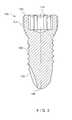
- FIG. 1shows a first perspective view of a bone fixation element according to an exemplary embodiment of the present invention
- FIG. 2shows a second perspective view of the bone fixation element of FIG. 1 ;
- FIG. 3shows a partial cross-sectional view of the bone fixation element of FIG. 1 ;
- FIG. 4shows a third perspective view of the bone fixation element of FIG. 1 ;
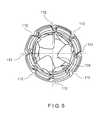
- FIG. 5shows a fourth perspective view of a head of the bone fixation element of FIG. 1 ;
- FIG. 6shows a perspective view of a bone fixation element according to an alternate embodiment of the present invention.
- FIG. 7shows a perspective view of a first surface of a bone plate according to the present invention.
- FIG. 8shows a perspective view of a second surface of the bone plate of FIG. 7 ;
- FIG. 9shows a lateral view of the bone plate of FIG. 7 .
- FIG. 10shows a partial cross-sectional view of a plate hole of the bone plate of FIG. 7 .
- the present inventionmay be further understood with reference to the following description and the appended drawings, wherein like elements are referred to with the same reference numerals.
- the present inventionrelates to the stabilization of bones and, in particular, to the stabilization of a fractured or otherwise damaged bone using a bone screw inserted through a bone fixation device (e.g., a bone plate).
- a bone fixation devicee.g., a bone plate.
- Exemplary embodiments of the present inventiondescribe a variable angle bone screw having a threaded head and a threaded shaft and having a carburized or nitrided outer surface configured to increase a surface hardness thereof to a desired level.
- the threaded headcomprises one or more grooves extending into an outer surface thereof at an angle relative to a longitudinal axis of the bone screw to aid in alignment of the threads of the head with threads of a variable angle screw hole of the bone fixation device.
- the shaftcomprises one or more notches extending into an outer surface thereof at any angle relative to the longitudinal axis within a permitted range of angulation, as will be described in greater detail later on.
- the bone platemay be formed of a metallic alloy exhibiting a hardness within a predetermined range.
- the bone screwmay be carburized or nitrided such that an outer surface of the bone screw has a hardness greater than a hardness of the bone plate.
- the exemplary bone screw according to the inventionprevents burring of the screw during insertion into the bone plate while providing a consistent connection strength to the bone and bone plate. Furthermore, the exemplary system according to the invention reduces galling during use while also providing an increased overall strength when compared to standard screws including increased yield strength, ultimate tensile strength and fatigue strength, as those skilled in the art will understand. It should be noted that the terms “proximal” and “distal” as used herein, are intended to refer to a direction toward (proximal) and away from (distal) a user of the device.
- a bone screw 100extends from a proximal end 102 comprising a head 104 along an elongated shaft 106 to a distal end 108 .
- an outer surface of the head 104is substantially spherical to permit variable angle insertion of the bone screw 100 into a bone fixation device 200 , as will be described in greater detail later on. It is noted, however, that the head 104 may be formed in any other shape without deviating from the scope of the invention (e.g., to permit a single-angle insertion of the bone screw 100 into the bone fixation device 200 ).
- the outer surface of the head 104is provided with threading 110 having a pitch configured to lockingly engage threading 212 formed on a walls of an opening 202 extending through the bone fixation device 200 , as will also be described in greater detail later on.
- One or more grooves 112may be provided on the head 104 , each groove 112 extending at least partially into the threads 110 and extending along an axis substantially angled with respect to a longitudinal axis 114 of the bone screw 100 .
- the grooves 112are configured to interrupt the thread 110 , thus creating a plurality of thread starts which aid in alignment of the thread 110 with the threads 212 of the hole 202 in an operative configuration especially when the bone screw 100 is inserted into a bone plate hole angled with respect to an axis of the bone plate hole (i.e., when the threading of the head 104 is misaligned with the threading of the bone plate hole).
- the grooves 112further permit the bone screw 100 to advance distally into the bone when rotated via a driving mechanism (not shown).
- Each of the grooves 112may be angled, for example, at an angle of approximately 8.5 ⁇ 1° relative to the line B-B, although any other angle may be used without deviating from the scope of the invention.
- the grooves 112are angled counter to a direction of the threading 110 .
- the line B-Bis perpendicular to the path of the threading 110 and the groove 112 is angled relative to the line B-B so that, traveling along the threading 110 from a proximal end 110 A thereof toward a distal end 110 B, the angle between the threading 110 and the groove 112 is greater than 90° on the proximal side of the thread and less than 90° on the distal side of the thread.
- the grooves 112extend at an angle of approximately 5-85° relative to the line B-B (i.e., 95° to 175° relative to the threading 110 ). In yet another embodiment, the grooves 112 may extend substantially parallel to the line B-B. The grooves 112 according to this embodiment extend along substantially a complete length of the threading 110 . In another embodiment (not shown), the grooves 112 may extend for only a partial length of the threading 110 .
- the bone screw 100may be formed with five grooves 112 disposed evenly circumferentially about the head 104 and equidistant from one another, as shown in FIG. 5 . Specifically, each of the grooves 112 in this embodiment is separated from adjacent grooves 112 by approximately 72°. In another embodiment (not shown), the bone screw 100 comprises six grooves 112 separated from one another by approximately 60°. In yet another embodiment, as shown in FIG. 6 , the bone screw 100 may comprise eight grooves 112 separated from one another by approximately 45°.
- the head 104may further comprises a recess 116 extending thereinto from the proximal end 102 .
- the recess 116is configured to permit engagement with a distal end of a driving mechanism (not shown) for applying torque to the bone screw 100 as would be understood by those skilled in the art.
- the embodiment of FIGS. 1-6is depicted with a torx-shaped recess 116 . It is noted, however, that any other shape may be employed without deviating from the scope of the invention (e.g., slotted, phillips, square, hexagonal, etc.), as those skilled in the art would understand.
- the shaft 106is provided with threading 118 having a pitch substantially the same as the pitch of the threads 110 .
- the pitch of the threading 118may be greater than or smaller than the pitch of the threads 110 .
- the threading 118 of the shaft 106may be formed with two leads, as those skilled in the art will understand.
- the multi-lead configuration of the threading 118aids in linear advancement of the bone screw 100 into the bone, as those skilled in the art will understand.
- the length of the shaft 106is generally selected to conform to requirements of a target procedure.
- a distal portion of the shaft 106may comprise one or more notches 120 configured to create a gap in the continuity of the threads 110 and permit self-tapping of the bone screw 100 , as those skilled in the art will understand.
- the distal portion of the shaft 106may taper to a smaller diameter at the distal end 106 to, for example, aid in insertion.
- the distal end 106may be sharpened or blunt as desired.
- the bone screw 100may be formed of a material selected to have a greater hardness that a material of a bone fixation device 200 with which it is to be employed.
- the bone screw 100may be formed of one of stainless steel and CCM (Co-28Cr-6Mo Alloy).
- the bone screw 100may then be carburized or nitrided to further increase a surface hardness thereof to approximately 68 HRC or more, as those skilled in the art will understand.
- the hardness of the bone screw 100may be approximately 67-74 HRC and, more particularly, 67.5-70.3 HRC.
- the bone fixation device 200may be formed of commercially pure Titanium grades 1, 2, 3 and 4, Ti-6Al-7Nb, Ti-6Al-4V, Ti-6Al-4V ELI, Ti-15Mo, CCM (Co-28Cr-6Mo Alloy), stainless steel or another material different than the material of the bone screw 100 .
- a hardness of the bone fixation device 200may be between approximately 75 HRB (e.g., for a CP1 material) and approximately 45 HRC (e.g., for a CCM material). This configuration prevents burring of the threads 110 of the bone screw 100 as they are inserted into the bone fixation device 100 while also increasing a holding strength of the bone fixation system in the bone.
- FIGS. 7-10depict the exemplary bone fixation device 200 according to the invention.
- the bone plate 200may, for example, be a 4.5 mm broad variable angle compression plate including eight holes 202 extending through a body 204 . Any or all of the holes 202 may be formed as variable angle combination holes comprising a first variable angle hole portion 206 and a second compression hole portion 208 open to the first hole portion.
- the first hole portion 206may comprise a first relief cut 210 formed adjacent a first surface 203 , a second cylindrical threaded portion 212 extending distally therefrom and a third relief cut 214 formed adjacent a second surface 205 configured to contact the bone in an operative configuration.
- the relief cut 210may extend at an angle of approximately 15° relative to a longitudinal axis of the hole 202 , although other angles may be used without deviating from the scope of the invention.
- the first hole portion 206further comprises one or more slots 207 provided on an outer wall thereof, the slots 207 extending substantially perpendicular to a screw hole axis.
- the slots 207interrupt the threads of the threaded portion 212 to provide multiple thread starts which aid in alignment of the threaded portion 212 with the bone screw 100 .
- the second hole portion 208may comprise a first tapered hole portion 216 and a second tapered hole portion 218 extending distally therefrom. It is noted that although the bone fixation device 200 is depicted with eight holes, any other number of holes may be used without deviating from the scope of the invention and these holes may include any variety of know bone screw mounting holes.
- the bone fixation device 200may also comprise any number and combination of variable angle holes, single holes and combination holes without deviating from the scope of the invention.
- the second surface 205may further comprise a plurality of undercuts 220 configured to reduce a contacting surface area between the bone fixation device 200 and the bone to, for example, reduce impairment of blood supply after implantation, as those skilled in the art will understand.
- the bone screw 100is inserted through the bone fixation device 200 and into the bone.
- a physician or other usermay select a desired angle of insertion to conform to the requirements of a particular procedure.
- Multiple thread starts provided by the grooves 112 provided on the head 104 and the slots 207 provided in the hole 202aid in alignment of the threads 110 of the head with the threaded portion 212 of the hole 202 .
- the carburized or nitrided outer surface of the bone screw 100prevents burring of the threads 110 .
- the increased rigidity of the bone screw 100 relative to the bone fixation device 200also permits removal and reinsertion of the bone screw 100 into the bone (e.g., to correct a position thereof within the bone) without causing a burring thereof.
Landscapes
- Health & Medical Sciences (AREA)
- Orthopedic Medicine & Surgery (AREA)
- Surgery (AREA)
- Life Sciences & Earth Sciences (AREA)
- Heart & Thoracic Surgery (AREA)
- Nuclear Medicine, Radiotherapy & Molecular Imaging (AREA)
- Engineering & Computer Science (AREA)
- Biomedical Technology (AREA)
- Neurology (AREA)
- Medical Informatics (AREA)
- Molecular Biology (AREA)
- Animal Behavior & Ethology (AREA)
- General Health & Medical Sciences (AREA)
- Public Health (AREA)
- Veterinary Medicine (AREA)
- Surgical Instruments (AREA)
- Materials For Medical Uses (AREA)
Abstract
Description
Claims (29)
Priority Applications (15)
| Application Number | Priority Date | Filing Date | Title |
|---|---|---|---|
| US13/534,831US9265542B2 (en) | 2012-06-27 | 2012-06-27 | Variable angle bone fixation device |
| KR1020157001705AKR102121720B1 (en) | 2012-06-27 | 2013-06-26 | Variable angle bone fixation device |
| IN10610DEN2014IN2014DN10610A (en) | 2012-06-27 | 2013-06-26 | |
| BR112014032663-0ABR112014032663B1 (en) | 2012-06-27 | 2013-06-26 | Bone fixation system |
| CN201711275520.3ACN107913097B (en) | 2012-06-27 | 2013-06-26 | Variable angle bone fixation device |
| EP18191410.2AEP3441031B1 (en) | 2012-06-27 | 2013-06-26 | Variable angle bone fixation device |
| US13/927,668US9387022B2 (en) | 2012-06-27 | 2013-06-26 | Variable angle bone fixation device |
| CA2877869ACA2877869C (en) | 2012-06-27 | 2013-06-26 | Variable angle bone fixation device |
| JP2015520462AJP6231092B2 (en) | 2012-06-27 | 2013-06-26 | Variable angle bone fixation device |
| PCT/US2013/047884WO2014004668A1 (en) | 2012-06-27 | 2013-06-26 | Variable angle bone fixation device |
| CN201380033672.6ACN104684494B (en) | 2012-06-27 | 2013-06-26 | Variable Angle Bone Fixation Device |
| EP13735166.4AEP2866706B2 (en) | 2012-06-27 | 2013-06-26 | Variable angle bone fixation device |
| US14/662,895US9277947B2 (en) | 2012-06-27 | 2015-03-19 | Variable angle bone fixation device |
| US15/009,616US10179013B2 (en) | 2012-06-27 | 2016-01-28 | Variable angle bone fixation device |
| JP2017200175AJP6513763B2 (en) | 2012-06-27 | 2017-10-16 | Bone fixation system and bone fixation system |
Applications Claiming Priority (1)
| Application Number | Priority Date | Filing Date | Title |
|---|---|---|---|
| US13/534,831US9265542B2 (en) | 2012-06-27 | 2012-06-27 | Variable angle bone fixation device |
Related Child Applications (2)
| Application Number | Title | Priority Date | Filing Date |
|---|---|---|---|
| US13/927,668Continuation-In-PartUS9387022B2 (en) | 2012-06-27 | 2013-06-26 | Variable angle bone fixation device |
| US14/662,895ContinuationUS9277947B2 (en) | 2012-06-27 | 2015-03-19 | Variable angle bone fixation device |
Publications (2)
| Publication Number | Publication Date |
|---|---|
| US20140005728A1 US20140005728A1 (en) | 2014-01-02 |
| US9265542B2true US9265542B2 (en) | 2016-02-23 |
Family
ID=48771759
Family Applications (3)
| Application Number | Title | Priority Date | Filing Date |
|---|---|---|---|
| US13/534,831Active2033-07-07US9265542B2 (en) | 2012-06-27 | 2012-06-27 | Variable angle bone fixation device |
| US14/662,895ActiveUS9277947B2 (en) | 2012-06-27 | 2015-03-19 | Variable angle bone fixation device |
| US15/009,616Active2033-04-25US10179013B2 (en) | 2012-06-27 | 2016-01-28 | Variable angle bone fixation device |
Family Applications After (2)
| Application Number | Title | Priority Date | Filing Date |
|---|---|---|---|
| US14/662,895ActiveUS9277947B2 (en) | 2012-06-27 | 2015-03-19 | Variable angle bone fixation device |
| US15/009,616Active2033-04-25US10179013B2 (en) | 2012-06-27 | 2016-01-28 | Variable angle bone fixation device |
Country Status (9)
| Country | Link |
|---|---|
| US (3) | US9265542B2 (en) |
| EP (2) | EP3441031B1 (en) |
| JP (2) | JP6231092B2 (en) |
| KR (1) | KR102121720B1 (en) |
| CN (2) | CN107913097B (en) |
| BR (1) | BR112014032663B1 (en) |
| CA (1) | CA2877869C (en) |
| IN (1) | IN2014DN10610A (en) |
| WO (1) | WO2014004668A1 (en) |
Cited By (17)
| Publication number | Priority date | Publication date | Assignee | Title |
|---|---|---|---|---|
| US20160143676A1 (en)* | 2012-06-27 | 2016-05-26 | DePuy Synthes Products, Inc. | Variable Angle Bone Fixation Device |
| US10231768B2 (en) | 2003-05-30 | 2019-03-19 | DePuy Synthes Products, Inc. | Methods for implanting bone plates |
| US10335211B2 (en) | 2004-01-26 | 2019-07-02 | DePuy Synthes Products, Inc. | Highly-versatile variable-angle bone plate system |
| US10342586B2 (en) | 2003-08-26 | 2019-07-09 | DePuy Synthes Products, Inc. | Bone plate |
| US10624686B2 (en) | 2016-09-08 | 2020-04-21 | DePuy Synthes Products, Inc. | Variable angel bone plate |
| US10772665B2 (en) | 2018-03-29 | 2020-09-15 | DePuy Synthes Products, Inc. | Locking structures for affixing bone anchors to a bone plate, and related systems and methods |
| US10820930B2 (en) | 2016-09-08 | 2020-11-03 | DePuy Synthes Products, Inc. | Variable angle bone plate |
| US10905476B2 (en) | 2016-09-08 | 2021-02-02 | DePuy Synthes Products, Inc. | Variable angle bone plate |
| US10925651B2 (en) | 2018-12-21 | 2021-02-23 | DePuy Synthes Products, Inc. | Implant having locking holes with collection cavity for shavings |
| US11013541B2 (en) | 2018-04-30 | 2021-05-25 | DePuy Synthes Products, Inc. | Threaded locking structures for affixing bone anchors to a bone plate, and related systems and methods |
| US11026727B2 (en) | 2018-03-20 | 2021-06-08 | DePuy Synthes Products, Inc. | Bone plate with form-fitting variable-angle locking hole |
| US11116557B2 (en)* | 2017-12-06 | 2021-09-14 | Stryker European Operations Holdings Llc | Orthopedic locking screw |
| US11259851B2 (en) | 2003-08-26 | 2022-03-01 | DePuy Synthes Products, Inc. | Bone plate |
| US11278334B2 (en) | 2019-05-22 | 2022-03-22 | DePuy Synthes Products, Inc. | Variable angle bone screw having a hardened head |
| US11291484B2 (en) | 2004-01-26 | 2022-04-05 | DePuy Synthes Products, Inc. | Highly-versatile variable-angle bone plate system |
| US20240024002A1 (en)* | 2017-02-22 | 2024-01-25 | In2Bones Usa, Llc | Adjustable angle bone fixation assembly |
| US12403009B2 (en) | 2019-06-12 | 2025-09-02 | United States Government As Represented By The Department Of Veterans Affairs | Femoral head arthroplasty system |
Families Citing this family (63)
| Publication number | Priority date | Publication date | Assignee | Title |
|---|---|---|---|---|
| US20140243912A1 (en)* | 2010-05-28 | 2014-08-28 | Jean-Pierre Mobasser | Awl-tipped pedicle screw and method of implanting same |
| WO2013095756A1 (en)* | 2011-12-20 | 2013-06-27 | Synthes Usa, Llc | Self centering feature for an intramedullary nail |
| WO2014111432A1 (en)* | 2013-01-15 | 2014-07-24 | Zimmer Gmbh | Surgical bone screw and implant system |
| US9510880B2 (en)* | 2013-08-13 | 2016-12-06 | Zimmer, Inc. | Polyaxial locking mechanism |
| WO2015090954A1 (en)* | 2013-12-17 | 2015-06-25 | Stichting Katholieke Universiteit | Intramedullary device for mid-shaft clavicle fractures |
| US9463057B2 (en)* | 2014-01-16 | 2016-10-11 | Amendia, Inc. | Orthopedic fastener |
| EP2932929B1 (en)* | 2014-04-15 | 2017-02-08 | Biedermann Technologies GmbH & Co. KG | A screw element for use in spinal, orthopedic or trauma surgery and a system of such a screw element and a screw driver adapted thereto |
| US10159517B2 (en) | 2014-07-07 | 2018-12-25 | Stryker European Holdings I, Llc | Bone plate with attachable wedge |
| CN104665910B (en)* | 2014-08-26 | 2018-01-12 | 无锡市闻泰百得医疗器械有限公司 | A kind of synthetism fastener of small-sized bone |
| CN104287820A (en)* | 2014-10-16 | 2015-01-21 | 常州市康辉医疗器械有限公司 | Steel plate screw system with universal locking function |
| AU2015336928B2 (en)* | 2014-10-24 | 2021-05-27 | Austofix Group Limited | A bone fixation system and a plate therefor |
| BR112017009310B1 (en)* | 2014-11-04 | 2022-10-11 | Depuy Synthes Products, Inc | BONE SCREW WITH BLONDE TIP |
| WO2016081528A1 (en)* | 2014-11-17 | 2016-05-26 | Bridging Medical, Llc | Bone compression systems |
| WO2016172601A1 (en)* | 2015-04-24 | 2016-10-27 | Biomet Manufacturing, Llc | Bone fixation systems, devices, and methods |
| US11076898B2 (en) | 2015-08-27 | 2021-08-03 | Globus Medical, Inc. | Proximal humeral stabilization system |
| US11197682B2 (en) | 2015-08-27 | 2021-12-14 | Globus Medical, Inc. | Proximal humeral stabilization system |
| US10687874B2 (en) | 2015-08-27 | 2020-06-23 | Globus Medical, Inc | Proximal humeral stabilization system |
| CN105213013B (en)* | 2015-09-08 | 2018-11-23 | 创生医疗器械(中国)有限公司 | Multi-shaft locking bone plate |
| US10130402B2 (en) | 2015-09-25 | 2018-11-20 | Globus Medical, Inc. | Bone fixation devices having a locking feature |
| US9974581B2 (en) | 2015-11-20 | 2018-05-22 | Globus Medical, Inc. | Expandable intramedullary systems and methods of using the same |
| US9795411B2 (en) | 2016-03-02 | 2017-10-24 | Globus Medical, Inc. | Fixators for bone stabilization and associated systems and methods |
| US10531905B2 (en) | 2016-04-19 | 2020-01-14 | Globus Medical, Inc. | Implantable compression screws |
| US20170319248A1 (en)* | 2016-05-06 | 2017-11-09 | Cardinal Health 247, Inc. | Variable-angle locking screws, and bone plate systems that include variable-angle locking screws |
| DE102016112154A1 (en)* | 2016-07-04 | 2018-01-04 | Karl Leibinger Medizintechnik Gmbh & Co. Kg | Implantation aids for the use of surface-sensitive implants |
| JP2018011691A (en)* | 2016-07-20 | 2018-01-25 | HOYA Technosurgical株式会社 | Hole structure of implant member |
| US10383668B2 (en) | 2016-08-17 | 2019-08-20 | Globus Medical, Inc. | Volar distal radius stabilization system |
| US11197701B2 (en) | 2016-08-17 | 2021-12-14 | Globus Medical, Inc. | Stabilization systems |
| US11331128B2 (en) | 2016-08-17 | 2022-05-17 | Globus Medical Inc. | Distal radius stabilization system |
| US10751098B2 (en) | 2016-08-17 | 2020-08-25 | Globus Medical Inc. | Stabilization systems |
| US11432857B2 (en) | 2016-08-17 | 2022-09-06 | Globus Medical, Inc. | Stabilization systems |
| US10420596B2 (en) | 2016-08-17 | 2019-09-24 | Globus Medical, Inc. | Volar distal radius stabilization system |
| US11141204B2 (en) | 2016-08-17 | 2021-10-12 | Globus Medical Inc. | Wrist stabilization systems |
| US10575884B2 (en) | 2016-08-17 | 2020-03-03 | Globus Medical, Inc. | Fracture plates, systems, and methods |
| US10687873B2 (en) | 2016-08-17 | 2020-06-23 | Globus Medical Inc. | Stabilization systems |
| US11213327B2 (en) | 2016-08-17 | 2022-01-04 | Globus Medical, Inc. | Fracture plates, systems, and methods |
| EP3295882B1 (en) | 2016-09-14 | 2019-06-05 | Grow-Ing Breitenstein | Bone screw |
| US10299847B2 (en) | 2016-09-22 | 2019-05-28 | Globus Medical, Inc. | Systems and methods for intramedullary nail implantation |
| US10881438B2 (en) | 2017-03-10 | 2021-01-05 | Globus Medical, Inc. | Clavicle fixation system |
| US10368928B2 (en) | 2017-03-13 | 2019-08-06 | Globus Medical, Inc. | Bone stabilization systems |
| US10905477B2 (en) | 2017-03-13 | 2021-02-02 | Globus Medical, Inc. | Bone stabilization systems |
| US10856920B2 (en) | 2017-09-13 | 2020-12-08 | Globus Medical Inc. | Bone stabilization systems |
| US11096730B2 (en) | 2017-09-13 | 2021-08-24 | Globus Medical Inc. | Bone stabilization systems |
| US12318122B2 (en) | 2017-09-13 | 2025-06-03 | Globus Medical, Inc. | Bone stabilization systems |
| KR102048889B1 (en)* | 2017-11-29 | 2019-12-03 | 에이블 주식회사 | Bending tool for medical bone joint plate and medical bone joint plate-bending kits |
| JP6980970B2 (en)* | 2018-01-26 | 2021-12-15 | メイラ株式会社 | Bone treatment tools, bone screws and bone plates |
| US11457964B2 (en) | 2018-02-27 | 2022-10-04 | 41Medical Ag | Variable angle bone plate system |
| US11224468B2 (en)* | 2018-03-02 | 2022-01-18 | Globus Medical, Inc. | Distal tibial plating system |
| US11071570B2 (en) | 2018-03-02 | 2021-07-27 | Globus Medical, Inc. | Distal tibial plating system |
| EP4108194A1 (en)* | 2018-03-02 | 2022-12-28 | Stryker European Holdings I, LLC | Bone plates and associated screws |
| US11141172B2 (en) | 2018-04-11 | 2021-10-12 | Globus Medical, Inc. | Method and apparatus for locking a drill guide in a polyaxial hole |
| US10765461B2 (en)* | 2018-06-01 | 2020-09-08 | DePuy Synthes Products, Inc. | Variable angle bone fixation device |
| CN113473918B (en)* | 2018-09-14 | 2024-10-01 | 博恩医疗器械股份有限公司 | Orthopedic bone screw |
| US11202663B2 (en) | 2019-02-13 | 2021-12-21 | Globus Medical, Inc. | Proximal humeral stabilization systems and methods thereof |
| HRP20190451A2 (en) | 2019-03-06 | 2020-09-18 | Janoš Kodvanj | Screw with a variable locking angle and the corresponding system of locking |
| US12185995B2 (en) | 2019-10-09 | 2025-01-07 | Globus Medical, Inc. | Bone stabilization systems |
| US11026698B2 (en)* | 2019-10-29 | 2021-06-08 | Skeletal Dynamics, Inc. | Osteotomy system and method of use |
| US11129627B2 (en) | 2019-10-30 | 2021-09-28 | Globus Medical, Inc. | Method and apparatus for inserting a bone plate |
| US11723647B2 (en) | 2019-12-17 | 2023-08-15 | Globus Medical, Inc. | Syndesmosis fixation assembly |
| US12161371B2 (en) | 2021-01-18 | 2024-12-10 | Treace Medical Concepts, Inc. | Contoured bone plate with locking screw for bone compression, particularly across a tarsometatarsal joint |
| US12064150B2 (en) | 2022-01-19 | 2024-08-20 | Globus Medical Inc. | System and method for treating bone fractures |
| WO2024112951A1 (en)* | 2022-11-22 | 2024-05-30 | Voom Medical Devices, Inc. | Orthopedic bone screw |
| FR3148360B1 (en)* | 2023-05-04 | 2025-04-18 | Novastep | Screw for osteosynthesis plate |
| PT118757A (en)* | 2023-06-27 | 2024-12-27 | Astrolabe Fabricacao De Implantes Medicos Lda | SCREW WITH VARIABLE ANGLE FIXING, INSERTIBLE INTO A THREADED HOLE IN A BONE PLATE |
Citations (29)
| Publication number | Priority date | Publication date | Assignee | Title |
|---|---|---|---|---|
| US5556483A (en) | 1994-04-18 | 1996-09-17 | Daido Hoxan, Inc. | Method of carburizing austenitic metal |
| US5593510A (en) | 1994-04-18 | 1997-01-14 | Daido Hoxan, Inc. | Method of carburizing austenitic metal |
| US5733287A (en)* | 1994-05-24 | 1998-03-31 | Synthes (U.S.A.) | Bone plate |
| US5792282A (en) | 1995-04-17 | 1998-08-11 | Daido Hoxan, Inc. | Method of carburizing austenitic stainless steel and austenitic stainless steel products obtained thereby |
| US6165597A (en) | 1998-08-12 | 2000-12-26 | Swagelok Company | Selective case hardening processes at low temperature |
| US6206881B1 (en) | 1995-09-06 | 2001-03-27 | Synthes (Usa) | Bone plate |
| US6322562B1 (en) | 1998-12-19 | 2001-11-27 | Dietmar Wolter | Fixation system for bones |
| US6461448B1 (en) | 1998-08-12 | 2002-10-08 | Swagelok Company | Low temperature case hardening processes |
| US20070083207A1 (en)* | 2005-09-21 | 2007-04-12 | Tara Ziolo | Variable angle bone fixation assembly |
| US20070088360A1 (en) | 2005-09-19 | 2007-04-19 | Orbay Jorge L | Bone stabilization system including multi-directional threaded fixation element |
| US20080234749A1 (en) | 2007-01-26 | 2008-09-25 | Zimmer Technology, Inc. | Bone plate providing threaded locking head screw capture |
| US20090018557A1 (en) | 2007-07-11 | 2009-01-15 | Perumala Corporation | Multi-axis connection and methods for internal spinal stabilizers |
| US20090143825A1 (en) | 2007-11-30 | 2009-06-04 | Robert Graham | Distal Tibia Plating System |
| US20090292318A1 (en)* | 2006-07-07 | 2009-11-26 | Precimed, S.A. | Bone Plate with Complex, Adjacent Holes Joined by a Relief-Space |
| US7648588B2 (en) | 2003-12-23 | 2010-01-19 | Rolls-Royce Corporation | Method for carburizing steel components |
| US20100016858A1 (en) | 2008-07-21 | 2010-01-21 | Gerlinde Michel | Carbon Fiber Reinforced Peek Bone Plate With Titanium Fixation Screws |
| US7695502B2 (en) | 2000-02-01 | 2010-04-13 | Depuy Products, Inc. | Bone stabilization system including plate having fixed-angle holes together with unidirectional locking screws and surgeon-directed locking screws |
| US20100094357A1 (en) | 2008-10-14 | 2010-04-15 | K2M, Inc. | Semi-constrained screw and spinal plate assembly |
| US20100100134A1 (en) | 2008-10-17 | 2010-04-22 | Osteomed L.P. | Angulated Locking Plate/Screw Interface |
| US20100168841A1 (en)* | 2007-01-16 | 2010-07-01 | Furst Joseph G | Metal alloys for medical devices |
| US7776076B2 (en)* | 2004-05-11 | 2010-08-17 | Synthes Usa, Llc | Bone plate |
| US20110022173A1 (en) | 2009-07-24 | 2011-01-27 | Warsaw Orthopedic, Inc. | Implant with an interference fit fastener |
| US20110077732A1 (en) | 2009-09-28 | 2011-03-31 | Biotronik Vi Patent Ag | Implant and method for manufacturing same |
| US20110106172A1 (en) | 2009-11-05 | 2011-05-05 | K2M, Inc. | Semi-constrained bone screw |
| US20110118795A1 (en)* | 2009-11-17 | 2011-05-19 | Adam Hashmi | Variable Angle Locking Buttress Pins |
| US20110224671A1 (en)* | 2009-09-14 | 2011-09-15 | Kenny Koay | Variable angle compression plate |
| US20110238122A1 (en) | 2008-10-31 | 2011-09-29 | Georg Gradl | Implant and bone screw having interlocking cams |
| WO2011154891A2 (en) | 2010-06-07 | 2011-12-15 | Carbofix Orthopedics Ltd. | Composite material bone implant and methods |
| US8382811B2 (en)* | 2009-06-19 | 2013-02-26 | U.S. Spine, Inc. | Triple lead bone screw |
Family Cites Families (31)
| Publication number | Priority date | Publication date | Assignee | Title |
|---|---|---|---|---|
| CH497891A (en)† | 1968-09-03 | 1970-10-31 | Straumann Inst Ag | Implant made of titanium or a titanium-based alloy, used for surgical bone treatment |
| CN87207475U (en)* | 1987-09-09 | 1988-08-24 | 无锡市百灵医疗器件厂 | Intramedullary needle |
| JPH089766B2 (en)* | 1989-07-10 | 1996-01-31 | 大同ほくさん株式会社 | Steel nitriding method |
| US5477864A (en)* | 1989-12-21 | 1995-12-26 | Smith & Nephew Richards, Inc. | Cardiovascular guidewire of enhanced biocompatibility |
| US5509933A (en)† | 1989-12-21 | 1996-04-23 | Smith & Nephew Richards, Inc. | Medical implants of hot worked, high strength, biocompatible, low modulus titanium alloys |
| CN1041117C (en)* | 1991-09-26 | 1998-12-09 | 大同酸素株式会社 | Hard austenitic stainless steel screw and process for preparing same |
| ES2135445T3 (en)† | 1992-02-07 | 1999-11-01 | Smith & Nephew Inc | SURFACE HARDENED BIOCOMPATIBLE METALLIC MEDICAL IMPLANTS. |
| DE4343117C2 (en)† | 1993-12-17 | 1999-11-04 | Dietmar Wolter | Bone fixation system |
| US5810830A (en)* | 1996-11-13 | 1998-09-22 | Howmedica Inc. | Machining assembly and methods for preparing the medullary cavity of a femur in hip arthroplasty |
| US5954724A (en)* | 1997-03-27 | 1999-09-21 | Davidson; James A. | Titanium molybdenum hafnium alloys for medical implants and devices |
| JP2000027829A (en) | 1998-07-10 | 2000-01-25 | Nitto Seiko Co Ltd | Austenitic stainless steel tapping screw |
| US6464448B1 (en) | 1998-09-01 | 2002-10-15 | Brooks Automation, Inc. | Substrate transport apparatus |
| CN1176241C (en)* | 1999-03-04 | 2004-11-17 | 陈蓓珠 | Smelting and production of super purified austenitic stainless steel |
| US6238491B1 (en)* | 1999-05-05 | 2001-05-29 | Davitech, Inc. | Niobium-titanium-zirconium-molybdenum (nbtizrmo) alloys for dental and other medical device applications |
| US8518090B2 (en)* | 2010-10-05 | 2013-08-27 | Acumed Llc | Fastener with serrated thread for attachment to a bone plate at a selectable angle |
| JP2004137600A (en)* | 2002-09-27 | 2004-05-13 | Nano Gijutsu Kenkyusho:Kk | Superhard, tough nanocrystal austenitic steel bulk material having excellent corrosion resistance |
| US7270679B2 (en)† | 2003-05-30 | 2007-09-18 | Warsaw Orthopedic, Inc. | Implants based on engineered metal matrix composite materials having enhanced imaging and wear resistance |
| DE20321551U1 (en) | 2003-08-26 | 2007-12-27 | Synthes Gmbh | bone plate |
| US8574268B2 (en)* | 2004-01-26 | 2013-11-05 | DePuy Synthes Product, LLC | Highly-versatile variable-angle bone plate system |
| JP4604140B2 (en)* | 2004-09-13 | 2010-12-22 | マニー株式会社 | Medical needle or blade |
| US8435238B2 (en)† | 2004-10-05 | 2013-05-07 | Michigan State University | Devices and methods for interlocking surgical screws and nails |
| CN101150994A (en)* | 2005-03-30 | 2008-03-26 | 特里马努斯医药有限公司 | Biological barrier for implants passing through mucosal or cutaneous tissues |
| CA2661444C (en) | 2006-08-15 | 2015-12-29 | Swissmedtechsolutions Ag | Trochanter retention plate |
| JP4684201B2 (en) | 2006-09-28 | 2011-05-18 | 京セラ株式会社 | Communication control apparatus and method |
| JP5022070B2 (en) | 2007-03-16 | 2012-09-12 | Jfe条鋼株式会社 | Manufacturing method of tapping screw for fastening high strength members |
| US20090228010A1 (en)* | 2008-03-10 | 2009-09-10 | Eduardo Gonzalez-Hernandez | Bone fixation system |
| SM200900081B (en)† | 2009-10-05 | 2010-11-12 | Hit Medica S P A | Plate system for osteosynthesis with angular stability multi-axial screws in polymeric material. |
| US20110218580A1 (en) | 2010-03-08 | 2011-09-08 | Stryker Trauma Sa | Bone fixation system with curved profile threads |
| US9265542B2 (en)* | 2012-06-27 | 2016-02-23 | DePuy Synthes Products, Inc. | Variable angle bone fixation device |
| CN202892072U (en)* | 2012-09-04 | 2013-04-24 | 王士军 | Antibacterial stainless steel implantable instrument |
| CN103142300B (en)* | 2013-02-06 | 2015-09-30 | 中国科学院金属研究所 | A kind of Novel multifunctional bone plate and application thereof |
- 2012
- 2012-06-27USUS13/534,831patent/US9265542B2/enactiveActive
- 2013
- 2013-06-26ININ10610DEN2014patent/IN2014DN10610A/enunknown
- 2013-06-26EPEP18191410.2Apatent/EP3441031B1/enactiveActive
- 2013-06-26CNCN201711275520.3Apatent/CN107913097B/enactiveActive
- 2013-06-26WOPCT/US2013/047884patent/WO2014004668A1/enactiveApplication Filing
- 2013-06-26EPEP13735166.4Apatent/EP2866706B2/enactiveActive
- 2013-06-26KRKR1020157001705Apatent/KR102121720B1/enactiveActive
- 2013-06-26CNCN201380033672.6Apatent/CN104684494B/enactiveActive
- 2013-06-26JPJP2015520462Apatent/JP6231092B2/enactiveActive
- 2013-06-26CACA2877869Apatent/CA2877869C/enactiveActive
- 2013-06-26BRBR112014032663-0Apatent/BR112014032663B1/ennot_activeIP Right Cessation
- 2015
- 2015-03-19USUS14/662,895patent/US9277947B2/enactiveActive
- 2016
- 2016-01-28USUS15/009,616patent/US10179013B2/enactiveActive
- 2017
- 2017-10-16JPJP2017200175Apatent/JP6513763B2/enactiveActive
Patent Citations (31)
| Publication number | Priority date | Publication date | Assignee | Title |
|---|---|---|---|---|
| US5556483A (en) | 1994-04-18 | 1996-09-17 | Daido Hoxan, Inc. | Method of carburizing austenitic metal |
| US5593510A (en) | 1994-04-18 | 1997-01-14 | Daido Hoxan, Inc. | Method of carburizing austenitic metal |
| US5733287A (en)* | 1994-05-24 | 1998-03-31 | Synthes (U.S.A.) | Bone plate |
| US5792282A (en) | 1995-04-17 | 1998-08-11 | Daido Hoxan, Inc. | Method of carburizing austenitic stainless steel and austenitic stainless steel products obtained thereby |
| US6206881B1 (en) | 1995-09-06 | 2001-03-27 | Synthes (Usa) | Bone plate |
| US6165597A (en) | 1998-08-12 | 2000-12-26 | Swagelok Company | Selective case hardening processes at low temperature |
| US6461448B1 (en) | 1998-08-12 | 2002-10-08 | Swagelok Company | Low temperature case hardening processes |
| US6322562B1 (en) | 1998-12-19 | 2001-11-27 | Dietmar Wolter | Fixation system for bones |
| US7695502B2 (en) | 2000-02-01 | 2010-04-13 | Depuy Products, Inc. | Bone stabilization system including plate having fixed-angle holes together with unidirectional locking screws and surgeon-directed locking screws |
| US7648588B2 (en) | 2003-12-23 | 2010-01-19 | Rolls-Royce Corporation | Method for carburizing steel components |
| US7776076B2 (en)* | 2004-05-11 | 2010-08-17 | Synthes Usa, Llc | Bone plate |
| US20070088360A1 (en) | 2005-09-19 | 2007-04-19 | Orbay Jorge L | Bone stabilization system including multi-directional threaded fixation element |
| US7905909B2 (en)* | 2005-09-19 | 2011-03-15 | Depuy Products, Inc. | Bone stabilization system including multi-directional threaded fixation element |
| US20070083207A1 (en)* | 2005-09-21 | 2007-04-12 | Tara Ziolo | Variable angle bone fixation assembly |
| US7955364B2 (en) | 2005-09-21 | 2011-06-07 | Ebi, Llc | Variable angle bone fixation assembly |
| US20090292318A1 (en)* | 2006-07-07 | 2009-11-26 | Precimed, S.A. | Bone Plate with Complex, Adjacent Holes Joined by a Relief-Space |
| US20100168841A1 (en)* | 2007-01-16 | 2010-07-01 | Furst Joseph G | Metal alloys for medical devices |
| US20080234749A1 (en) | 2007-01-26 | 2008-09-25 | Zimmer Technology, Inc. | Bone plate providing threaded locking head screw capture |
| US20090018557A1 (en) | 2007-07-11 | 2009-01-15 | Perumala Corporation | Multi-axis connection and methods for internal spinal stabilizers |
| US20090143825A1 (en) | 2007-11-30 | 2009-06-04 | Robert Graham | Distal Tibia Plating System |
| US20100016858A1 (en) | 2008-07-21 | 2010-01-21 | Gerlinde Michel | Carbon Fiber Reinforced Peek Bone Plate With Titanium Fixation Screws |
| US20100094357A1 (en) | 2008-10-14 | 2010-04-15 | K2M, Inc. | Semi-constrained screw and spinal plate assembly |
| US20100100134A1 (en) | 2008-10-17 | 2010-04-22 | Osteomed L.P. | Angulated Locking Plate/Screw Interface |
| US20110238122A1 (en) | 2008-10-31 | 2011-09-29 | Georg Gradl | Implant and bone screw having interlocking cams |
| US8382811B2 (en)* | 2009-06-19 | 2013-02-26 | U.S. Spine, Inc. | Triple lead bone screw |
| US20110022173A1 (en) | 2009-07-24 | 2011-01-27 | Warsaw Orthopedic, Inc. | Implant with an interference fit fastener |
| US20110224671A1 (en)* | 2009-09-14 | 2011-09-15 | Kenny Koay | Variable angle compression plate |
| US20110077732A1 (en) | 2009-09-28 | 2011-03-31 | Biotronik Vi Patent Ag | Implant and method for manufacturing same |
| US20110106172A1 (en) | 2009-11-05 | 2011-05-05 | K2M, Inc. | Semi-constrained bone screw |
| US20110118795A1 (en)* | 2009-11-17 | 2011-05-19 | Adam Hashmi | Variable Angle Locking Buttress Pins |
| WO2011154891A2 (en) | 2010-06-07 | 2011-12-15 | Carbofix Orthopedics Ltd. | Composite material bone implant and methods |
Non-Patent Citations (2)
| Title |
|---|
| "Cyprus Anterior Cervical Plate System", Surgical Technique, Biomet Spine, 2008, 24 sheets. |
| "Forerunner plating System", Featuring SphereLock Technology, Biomet Trauma, 2010, 27 sheets. |
Cited By (20)
| Publication number | Priority date | Publication date | Assignee | Title |
|---|---|---|---|---|
| US10231768B2 (en) | 2003-05-30 | 2019-03-19 | DePuy Synthes Products, Inc. | Methods for implanting bone plates |
| US11259851B2 (en) | 2003-08-26 | 2022-03-01 | DePuy Synthes Products, Inc. | Bone plate |
| US10342586B2 (en) | 2003-08-26 | 2019-07-09 | DePuy Synthes Products, Inc. | Bone plate |
| US10335211B2 (en) | 2004-01-26 | 2019-07-02 | DePuy Synthes Products, Inc. | Highly-versatile variable-angle bone plate system |
| US11291484B2 (en) | 2004-01-26 | 2022-04-05 | DePuy Synthes Products, Inc. | Highly-versatile variable-angle bone plate system |
| US10179013B2 (en)* | 2012-06-27 | 2019-01-15 | DePuy Synthes Products, Inc. | Variable angle bone fixation device |
| US20160143676A1 (en)* | 2012-06-27 | 2016-05-26 | DePuy Synthes Products, Inc. | Variable Angle Bone Fixation Device |
| US10624686B2 (en) | 2016-09-08 | 2020-04-21 | DePuy Synthes Products, Inc. | Variable angel bone plate |
| US10905476B2 (en) | 2016-09-08 | 2021-02-02 | DePuy Synthes Products, Inc. | Variable angle bone plate |
| US10820930B2 (en) | 2016-09-08 | 2020-11-03 | DePuy Synthes Products, Inc. | Variable angle bone plate |
| US11529176B2 (en) | 2016-09-08 | 2022-12-20 | DePuy Synthes Products, Inc. | Variable angle bone plate |
| US20240024002A1 (en)* | 2017-02-22 | 2024-01-25 | In2Bones Usa, Llc | Adjustable angle bone fixation assembly |
| US11116557B2 (en)* | 2017-12-06 | 2021-09-14 | Stryker European Operations Holdings Llc | Orthopedic locking screw |
| US12108972B2 (en) | 2017-12-06 | 2024-10-08 | Stryker European Operations Holdings Llc | Orthopedic locking screw |
| US11026727B2 (en) | 2018-03-20 | 2021-06-08 | DePuy Synthes Products, Inc. | Bone plate with form-fitting variable-angle locking hole |
| US10772665B2 (en) | 2018-03-29 | 2020-09-15 | DePuy Synthes Products, Inc. | Locking structures for affixing bone anchors to a bone plate, and related systems and methods |
| US11013541B2 (en) | 2018-04-30 | 2021-05-25 | DePuy Synthes Products, Inc. | Threaded locking structures for affixing bone anchors to a bone plate, and related systems and methods |
| US10925651B2 (en) | 2018-12-21 | 2021-02-23 | DePuy Synthes Products, Inc. | Implant having locking holes with collection cavity for shavings |
| US11278334B2 (en) | 2019-05-22 | 2022-03-22 | DePuy Synthes Products, Inc. | Variable angle bone screw having a hardened head |
| US12403009B2 (en) | 2019-06-12 | 2025-09-02 | United States Government As Represented By The Department Of Veterans Affairs | Femoral head arthroplasty system |
Also Published As
| Publication number | Publication date |
|---|---|
| JP6231092B2 (en) | 2017-11-15 |
| KR102121720B1 (en) | 2020-06-12 |
| EP2866706B1 (en) | 2018-09-19 |
| EP2866706B2 (en) | 2021-12-22 |
| BR112014032663A2 (en) | 2017-06-27 |
| CN104684494B (en) | 2018-01-02 |
| WO2014004668A1 (en) | 2014-01-03 |
| JP2018020202A (en) | 2018-02-08 |
| IN2014DN10610A (en) | 2015-09-11 |
| CN107913097B (en) | 2021-07-09 |
| US20140005728A1 (en) | 2014-01-02 |
| CN104684494A (en) | 2015-06-03 |
| JP2015525616A (en) | 2015-09-07 |
| US20160143676A1 (en) | 2016-05-26 |
| BR112014032663B1 (en) | 2022-03-29 |
| EP3441031A1 (en) | 2019-02-13 |
| KR20150023853A (en) | 2015-03-05 |
| CA2877869C (en) | 2020-03-31 |
| EP3441031B1 (en) | 2023-03-08 |
| US9277947B2 (en) | 2016-03-08 |
| JP6513763B2 (en) | 2019-05-15 |
| CN107913097A (en) | 2018-04-17 |
| EP2866706A1 (en) | 2015-05-06 |
| US10179013B2 (en) | 2019-01-15 |
| US20150190185A1 (en) | 2015-07-09 |
| CA2877869A1 (en) | 2014-01-03 |
Similar Documents
| Publication | Publication Date | Title |
|---|---|---|
| US10179013B2 (en) | Variable angle bone fixation device | |
| US10682169B2 (en) | Bone screw | |
| EP3033018B1 (en) | Polyaxial locking mechanism | |
| CA2775733C (en) | Variable angle locking buttress pins | |
| US9339315B2 (en) | Bone fixation system with curved profile threads | |
| KR101104660B1 (en) | Locking bone plate | |
| JP4971195B2 (en) | Plates and screws for fracture treatment | |
| US8668725B2 (en) | Bone screw | |
| EP2364657B1 (en) | Bone fixation system with curved profile threads | |
| US20050021036A1 (en) | Self-drilling, self-tapping bone screw | |
| WO2014053438A1 (en) | Intramedullary nail and implant system comprising the nail | |
| US10660680B2 (en) | Bone treating device, bone treating screw and bone treating plate | |
| EP3096697B1 (en) | Elongated pin for application of an external fixator |
Legal Events
| Date | Code | Title | Description |
|---|---|---|---|
| AS | Assignment | Owner name:SYNTHES USA, LLC, PENNSYLVANIA Free format text:ASSIGNMENT OF ASSIGNORS INTEREST;ASSIGNOR:SYNTHES GMBH;REEL/FRAME:029048/0267 Effective date:20120716 Owner name:SYNTHES GMBH, SWITZERLAND Free format text:ASSIGNMENT OF ASSIGNORS INTEREST;ASSIGNOR:ROCCI, MIRKO;REEL/FRAME:029048/0221 Effective date:20120716 Owner name:SYNTHES GMBH, SWITZERLAND Free format text:ASSIGNMENT OF CERTAIN FOREIGN RIGHTS;ASSIGNOR:SYNTHES USA, LLC;REEL/FRAME:029047/0677 Effective date:20120723 Owner name:SYNTHES USA, LLC, PENNSYLVANIA Free format text:ASSIGNMENT OF ASSIGNORS INTEREST;ASSIGNORS:KOAY, KENNY;MCMILLAN, ROD;KOBAYASHI, KENNETH;AND OTHERS;SIGNING DATES FROM 20120629 TO 20120710;REEL/FRAME:029047/0210 | |
| AS | Assignment | Owner name:HAND INNOVATIONS LLC, FLORIDA Free format text:ASSIGNMENT OF ASSIGNORS INTEREST;ASSIGNOR:DEPUY SPINE, LLC;REEL/FRAME:030359/0001 Effective date:20121230 Owner name:DEPUY SPINE, LLC, MASSACHUSETTS Free format text:ASSIGNMENT OF ASSIGNORS INTEREST;ASSIGNOR:SYNTHES USA, LLC;REEL/FRAME:030358/0945 Effective date:20121230 Owner name:DEPUY SYNTHES PRODUCTS, LLC, MASSACHUSETTS Free format text:CHANGE OF NAME;ASSIGNOR:HAND INNOVATIONS LLC;REEL/FRAME:030359/0036 Effective date:20121231 | |
| AS | Assignment | Owner name:DEPUY SYNTHES PRODUCTS, INC., MASSACHUSETTS Free format text:CHANGE OF NAME;ASSIGNOR:DEPUY SYNTHES PRODUCTS, LLC;REEL/FRAME:035074/0647 Effective date:20141219 | |
| FEPP | Fee payment procedure | Free format text:PAYOR NUMBER ASSIGNED (ORIGINAL EVENT CODE: ASPN); ENTITY STATUS OF PATENT OWNER: LARGE ENTITY | |
| STCF | Information on status: patent grant | Free format text:PATENTED CASE | |
| AS | Assignment | Owner name:HAND INNOVATIONS LLC, FLORIDA Free format text:CORRECTIVE ASSIGNMENT TO CORRECT THE INCORRECT APPL. NO. 13/486,591 PREVIOUSLY RECORDED AT REEL: 030359 FRAME: 0001. ASSIGNOR(S) HEREBY CONFIRMS THE ASSIGNMENT;ASSIGNOR:DEPUY SPINE, LLC;REEL/FRAME:042621/0565 Effective date:20121230 | |
| AS | Assignment | Owner name:DEPUY SPINE, LLC, MASSACHUSETTS Free format text:CORRECTIVE ASSIGNMENT TO CORRECT THE INCORRECT APPLICATION NO. US 13/486,591 PREVIOUSLY RECORDED ON REEL 030358 FRAME 0945. ASSIGNOR(S) HEREBY CONFIRMS THE ASSIGNMENT;ASSIGNOR:SYNTHES USA, LLC;REEL/FRAME:042687/0849 Effective date:20121230 | |
| MAFP | Maintenance fee payment | Free format text:PAYMENT OF MAINTENANCE FEE, 4TH YEAR, LARGE ENTITY (ORIGINAL EVENT CODE: M1551); ENTITY STATUS OF PATENT OWNER: LARGE ENTITY Year of fee payment:4 | |
| MAFP | Maintenance fee payment | Free format text:PAYMENT OF MAINTENANCE FEE, 8TH YEAR, LARGE ENTITY (ORIGINAL EVENT CODE: M1552); ENTITY STATUS OF PATENT OWNER: LARGE ENTITY Year of fee payment:8 |