US9265486B2 - Surgical device - Google Patents
Surgical deviceDownload PDFInfo
- Publication number
- US9265486B2 US9265486B2US13/586,737US201213586737AUS9265486B2US 9265486 B2US9265486 B2US 9265486B2US 201213586737 AUS201213586737 AUS 201213586737AUS 9265486 B2US9265486 B2US 9265486B2
- Authority
- US
- United States
- Prior art keywords
- plane
- repositionable
- control
- link
- end effector
- Prior art date
- Legal status (The legal status is an assumption and is not a legal conclusion. Google has not performed a legal analysis and makes no representation as to the accuracy of the status listed.)
- Active, expires
Links
- 239000012636effectorSubstances0.000claimsdescription77
- 230000008878couplingEffects0.000claimsdescription2
- 238000010168coupling processMethods0.000claimsdescription2
- 238000005859coupling reactionMethods0.000claimsdescription2
- 230000007246mechanismEffects0.000description87
- 210000004197pelvisAnatomy0.000description55
- 230000000712assemblyEffects0.000description20
- 238000000429assemblyMethods0.000description20
- 239000000463materialSubstances0.000description20
- 239000011295pitchSubstances0.000description18
- 238000002679ablationMethods0.000description12
- 210000003484anatomyAnatomy0.000description10
- 230000007704transitionEffects0.000description10
- 230000007423decreaseEffects0.000description9
- 239000004744fabricSubstances0.000description8
- 238000006243chemical reactionMethods0.000description6
- 210000003739neckAnatomy0.000description6
- PEDCQBHIVMGVHV-UHFFFAOYSA-NGlycerineChemical compoundOCC(O)COPEDCQBHIVMGVHV-UHFFFAOYSA-N0.000description5
- 210000001008atrial appendageAnatomy0.000description5
- 230000008859changeEffects0.000description5
- RTAQQCXQSZGOHL-UHFFFAOYSA-NTitaniumChemical compound[Ti]RTAQQCXQSZGOHL-UHFFFAOYSA-N0.000description4
- 230000003993interactionEffects0.000description4
- 230000014759maintenance of locationEffects0.000description4
- 230000002093peripheral effectEffects0.000description4
- 239000010936titaniumSubstances0.000description4
- 229910052719titaniumInorganic materials0.000description4
- 230000008901benefitEffects0.000description3
- 230000000994depressogenic effectEffects0.000description3
- 230000002401inhibitory effectEffects0.000description3
- 238000000034methodMethods0.000description3
- 230000000717retained effectEffects0.000description3
- 241001272720Medialuna californiensisSpecies0.000description2
- 230000009471actionEffects0.000description2
- 230000000903blocking effectEffects0.000description2
- 230000006835compressionEffects0.000description2
- 238000007906compressionMethods0.000description2
- 230000001186cumulative effectEffects0.000description2
- 238000005520cutting processMethods0.000description2
- 230000003247decreasing effectEffects0.000description2
- 230000000881depressing effectEffects0.000description2
- 238000003384imaging methodMethods0.000description2
- 238000005304joiningMethods0.000description2
- 238000002324minimally invasive surgeryMethods0.000description2
- 229910001000nickel titaniumInorganic materials0.000description2
- 229920000728polyesterPolymers0.000description2
- 238000003825pressingMethods0.000description2
- 125000006850spacer groupChemical group0.000description2
- 230000007480spreadingEffects0.000description2
- 238000003892spreadingMethods0.000description2
- 238000001356surgical procedureMethods0.000description2
- 210000003813thumbAnatomy0.000description2
- JOYRKODLDBILNP-UHFFFAOYSA-NEthyl urethaneChemical compoundCCOC(N)=OJOYRKODLDBILNP-UHFFFAOYSA-N0.000description1
- 239000000853adhesiveSubstances0.000description1
- 230000001070adhesive effectEffects0.000description1
- 230000003466anti-cipated effectEffects0.000description1
- 238000005452bendingMethods0.000description1
- 239000000560biocompatible materialSubstances0.000description1
- 230000000295complement effectEffects0.000description1
- 238000010276constructionMethods0.000description1
- 238000007796conventional methodMethods0.000description1
- 230000009977dual effectEffects0.000description1
- 230000000694effectsEffects0.000description1
- 239000007943implantSubstances0.000description1
- 210000005248left atrial appendageAnatomy0.000description1
- 238000004519manufacturing processMethods0.000description1
- 229910052751metalInorganic materials0.000description1
- 239000002184metalSubstances0.000description1
- 230000036961partial effectEffects0.000description1
- 230000002829reductive effectEffects0.000description1
- 239000010935stainless steelSubstances0.000description1
- 229910001220stainless steelInorganic materials0.000description1
- 230000003068static effectEffects0.000description1
- 239000000758substrateSubstances0.000description1
- 238000003466weldingMethods0.000description1
- 238000004804windingMethods0.000description1
Images


Classifications
- A—HUMAN NECESSITIES
- A61—MEDICAL OR VETERINARY SCIENCE; HYGIENE
- A61B—DIAGNOSIS; SURGERY; IDENTIFICATION
- A61B17/00—Surgical instruments, devices or methods
- A61B17/10—Surgical instruments, devices or methods for applying or removing wound clamps, e.g. containing only one clamp or staple; Wound clamp magazines
- A—HUMAN NECESSITIES
- A61—MEDICAL OR VETERINARY SCIENCE; HYGIENE
- A61B—DIAGNOSIS; SURGERY; IDENTIFICATION
- A61B17/00—Surgical instruments, devices or methods
- A—HUMAN NECESSITIES
- A61—MEDICAL OR VETERINARY SCIENCE; HYGIENE
- A61B—DIAGNOSIS; SURGERY; IDENTIFICATION
- A61B17/00—Surgical instruments, devices or methods
- A61B17/00234—Surgical instruments, devices or methods for minimally invasive surgery
- A—HUMAN NECESSITIES
- A61—MEDICAL OR VETERINARY SCIENCE; HYGIENE
- A61B—DIAGNOSIS; SURGERY; IDENTIFICATION
- A61B17/00—Surgical instruments, devices or methods
- A61B17/08—Wound clamps or clips, i.e. not or only partly penetrating the tissue ; Devices for bringing together the edges of a wound
- A61B17/083—Clips, e.g. resilient
- A—HUMAN NECESSITIES
- A61—MEDICAL OR VETERINARY SCIENCE; HYGIENE
- A61B—DIAGNOSIS; SURGERY; IDENTIFICATION
- A61B17/00—Surgical instruments, devices or methods
- A61B17/12—Surgical instruments, devices or methods for ligaturing or otherwise compressing tubular parts of the body, e.g. blood vessels or umbilical cord
- A61B17/122—Clamps or clips, e.g. for the umbilical cord
- A61B17/1227—Spring clips
- A—HUMAN NECESSITIES
- A61—MEDICAL OR VETERINARY SCIENCE; HYGIENE
- A61B—DIAGNOSIS; SURGERY; IDENTIFICATION
- A61B17/00—Surgical instruments, devices or methods
- A61B17/12—Surgical instruments, devices or methods for ligaturing or otherwise compressing tubular parts of the body, e.g. blood vessels or umbilical cord
- A61B17/128—Surgical instruments, devices or methods for ligaturing or otherwise compressing tubular parts of the body, e.g. blood vessels or umbilical cord for applying or removing clamps or clips
- A61B17/1285—Surgical instruments, devices or methods for ligaturing or otherwise compressing tubular parts of the body, e.g. blood vessels or umbilical cord for applying or removing clamps or clips for minimally invasive surgery
- A—HUMAN NECESSITIES
- A61—MEDICAL OR VETERINARY SCIENCE; HYGIENE
- A61B—DIAGNOSIS; SURGERY; IDENTIFICATION
- A61B17/00—Surgical instruments, devices or methods
- A61B2017/00367—Details of actuation of instruments, e.g. relations between pushing buttons, or the like, and activation of the tool, working tip, or the like
Definitions
- the present inventionis directed to surgical equipment and, more specifically, to surgical equipment that may be used in minimally invasive procedures.
- the disclosurealso relates to surgical equipment to facilitate the positioning and deployment of an atrial appendage occlusion device.
- the disclosurerelates to surgical equipment that is adapted to accommodate or work in tandem with flexible endoscopes.
- the exemplary embodiments disclosed hereininclude one or more active or passive repositioning mechanisms.
- an active repositioning mechanismprovides for infinite adjustments as the user is physically operating a control to directly manipulate the repositioning of an end effector.
- a passive repositioning mechanismcan be thought of as acting similar to a light switch, either off or on. In this manner, the passive repositioning mechanism either allows or disallows repositioning of the end effector, but is not responsible for actively manipulating the position of the end effector.
- a laparoscopic devicemay incorporate both an active and a passive repositioning mechanism to control movements in different directions, such as pitch and yaw.
- the exemplary embodimentsalso include active repositioning mechanisms that provide a certain motion conversion.
- active repositioning mechanismsthat provide a certain motion conversion.
- a ninety degree change in position of the controllerwould result in a forty-five degree change in position at the end effector.
- certain parametersmay be modified to provide different motion conversion depending upon the end application and user preference.
- It is a first aspect of the present invention to provide a medical instrumentcomprising: (a) a first joint comprising a first member and a second member, the first member configured to be repositionable with respect to the second member in an X-Y plane; (b) a second joint operatively coupled to the first joint, the second joint comprising a third member and a fourth member, the third member configured to be repositionable with respect to the fourth member in a Y-Z plane perpendicular to the X-Y plane; and, (c) a controller operatively coupled to the first joint and the second joint, the controller including a first control configured to direct repositioning of at least one of the first member and the second member, and a second control configured to direct repositioning of at least one of the third member and the fourth member.
- the first controlcomprises a passive control configured to be repositionable between a first position, that allows free movement between the first member and the second member within the X-Y plane, and a second position that retards movement between the first member and the second member within the X-Y plane
- the second controlcomprises an active control configured to be repositionable among an infinite number of positions, where each of the infinite number of positions orients the third member with respect to the fourth member in a different position within the Y-Z plane.
- the passive controlincludes a lever repositionably mounted to a housing of the controller, the lever coupled to a passive control line, and the passive control line is also coupled to a repositionable catch configured to engage at least one of the first member and the second member to retard movement between the first member and the second member within the X-Y plane.
- the repositionable catchis biased, using a spring, to retard movement between the first member and the second member within the X-Y plane, and the lever is configured to be repositionable to tension the passive control line to overcome the bias of the spring to allow movement between the first member and the second member within the X-Y plane.
- the instrumentfurther includes a longitudinal conduit extending between the controller and the first joint, wherein at least a portion of the passive control line extends through the longitudinal conduit.
- the instrumentfurther includes a longitudinal conduit extending between the controller and the first joint, where the first member is mounted to the controller, and the second member is repositionably mounted to the first member.
- the first memberis elongated and includes an internal cavity that at least partially houses a repositionable catch to retard movement between the first member and the second member within the X-Y plane, and at least one of the first member and the longitudinal conduit houses a spring biasing the repositionable catch to retard movement between the first member and the second member within the X-Y plane.
- At least one of the first member and the second memberincludes a projection
- at least one of the first member and the second memberincludes a cavity configured to receive the projection
- the cavityis at least partially defined by a bearing surface
- the projectionis configured to contact the bearing surface when movement occurs between the first member and the second member within the X-Y plane.
- the first memberincludes the cavity
- the second memberincludes the projection
- the repositionable catchincludes at least one tooth
- the second memberincludes at least one tooth configured to engage the at least one tooth of the repositionable catch to retard movement between the first member and the second member within the X-Y plane.
- the cavitycomprises a first cavity and a second cavity spaced apart and facing one another
- the projectioncomprises a first projection and a second projection spaced apart and facing away from one another
- the first cavityis configured to receive the first projection
- the second cavityis configured to receive the second projection
- the first membercomprises a clevis
- the second membercomprises a pelvis.
- the first controlcomprises a passive control configured to be repositionable between a first position, that allows free movement between the first member and the second member within the X-Y plane, and a second position that retards movement between the first member and the second member within the X-Y plane
- the clevisincludes an internal cavity that at least partially receives a repositionable catch and a bias spring
- the repositionable catchcomprises a portion of the first control
- the first controlalso includes an actuator repositionable mounted to the controller
- the first controlfurther includes a tether concurrently coupled to the actuator and the repositionable catch.
- the pelvisincludes a first pelvis half and a second pelvis half, and the first pelvis half and the second pelvis half are identical.
- the active controlincludes an actuator repositionably mounted to a housing of the controller, the actuator operatively coupled to an active control line, and the active control line is coupled to at least one of the third member and the fourth member to control movement between the third member and the fourth member within the Y-Z plane.
- the actuatorincludes a wheel and a link plate, the wheel includes a spiral cavity, and the linkplate includes a projection configured to be received within the spiral cavity of the wheel.
- the actuatorincludes a wheel and a link plate, the linkplate includes a spiral cavity, and the wheel includes a projection configured to be received within the spiral cavity of the linkplate.
- the actuatorincludes a wheel and a link plate, the linkplate includes a cavity, and the wheel includes a spiral projection configured to be received within the cavity of the linkplate.
- the actuatorincludes a wheel and a link plate, the wheel includes a cavity, and the linkplate includes a spiral projection configured to be received within the cavity of the wheel.
- the second controlcomprises an active control configured to be repositionable among an infinite number of positions, where each of the infinite number of positions orients the third member with respect to the fourth member in a different position within the Y-Z plane, the second member is mounted to the third member, and the third member is repositionably mounted to the fourth member.
- the fourth memberis elongated and includes an internal cavity that at least partially houses a repositionable pull link, and the fourth member includes a channel configured to receive at least a portion of the active control line.
- the channelincludes a first arcuate segment and a second arcuate segment
- the active control lineincludes a first active control line and a second active control line
- the first arcuate segmentis configured to receive the first active control line
- the second arcuate segmentis configured to receive the second active control line
- at least a portion of the first active control lineis secured to the fourth member
- at least a portion of the second active control lineis secured to the fourth member.
- At least one of the third member and the fourth memberincludes a projection
- at least one of the third member and the fourth memberincludes a cavity configured to receive the projection
- the cavityis at least partially defined by a bearing surface
- the projectionis configured to contact the bearing surface when movement occurs between the third member and the fourth member within the Y-Z plane.
- the fourth memberincludes the cavity
- the third memberincludes the projection.
- the cavitycomprises a first cavity and a second cavity spaced apart and facing away from one another
- the projectioncomprises a first projection and a second projection spaced apart and facing one another
- the first cavityis configured to receive the first projection
- the second cavityis configured to receive the second projection.
- the second controlcomprises an active control configured to be repositionable among an infinite number of positions, where each of the infinite number of positions orients the third member with respect to the fourth member in a different position within the Y-Z plane, the third member comprises a pelvis, and the fourth member comprises a yoke.
- the active controlincludes an actuator repositionably mounted to a housing of the controller, the actuator operatively coupled to a first active control line and a second active control line, the yoke includes an internal cavity that at least partially receives a repositionable pull link, the yoke includes a first channel configured to receive at least a portion of the first active control line, and a second configured to receive at least a portion of the second active control line, at least a portion of the first active control line and the second active control line are secured to the yoke.
- the second member and the third memberare mounted to one another, and the second member and the third member cooperate to forma pelvis.
- the actuatorincludes a first wheel, a first link plate, a second wheel, and a second link plate
- the first and second wheelseach include a spiral cavity
- the first and second linkplateseach include a projection configured to be received within a respective spiral cavity of the first and second wheels
- the first active control lineis coupled to the first link plate
- the second active control lineis coupled to the second link plate.
- the first wheelis a mirror image of the second wheel.
- the spiral cavity of each of the first and second wheelsincludes an arcuate wall that delineates the spiral cavity
- the projection of each of the first and second link platesincludes a curved surface that is configured to contact the arcuate wall of a respective spiral cavity.
- the first controlcomprises a first passive control configured to be repositionable between a first position, that allows free movement between the first member and the second member within the X-Y plane, and a second position that inhibits movement between the first member and the second member within the X-Y plane
- the second controlcomprises a second passive control configured to be repositionable between a first position, that allows free movement between the third member and the fourth member within the Y-Z plane, and a second position that inhibits movement between the third member and the fourth member within the Y-Z plane.
- the first passive controlincludes an actuator repositionably mounted to a housing of the controller, the actuator coupled to a first passive control line, and the first passive control line is also coupled to at least one of the first member and the second member to retard movement between the first member and the second member within the X-Y plane.
- the actuatoris configured to be repositionable to allow movement between the first member and the second member within the X-Y plane. In another more detailed embodiment.
- the first memberis elongated and includes an internal cavity that at least partially houses a repositionable catch to retard movement between the first member and the second member within the X-Y plane, and at least one of the first member and the longitudinal conduit houses a spring biasing the repositionable catch to retard movement between the first member and the second member within the X-Y plane.
- At least one of the first member and the second memberincludes a projection
- at least one of the first member and the second memberincludes a cavity configured to receive the projection
- the cavityis at least partially defined by a bearing surface
- the projectionis configured to contact the bearing surface when movement occurs between the first member and the second member within the X-Y plane.
- the first memberincludes the cavity
- the second memberincludes the projection
- the repositionable catchincludes at least one tooth
- the second memberincludes at least one tooth configured to engage the at least one tooth of the repositionable catch to retard movement between the first member and the second member within the X-Y plane.
- the cavitycomprises a first cavity and a second cavity spaced apart and facing one another
- the projectioncomprises a first projection and a second projection spaced apart and facing away from one another
- the first cavityis configured to receive the first projection
- the second cavityis configured to receive the second projection.
- the first membercomprises a clevis
- the second membercomprises a pelvis.
- the clevisincludes an internal cavity that at least partially receives a repositionable catch and a bias spring
- the repositionable catchcomprises a portion of the first control
- the first controlalso includes an actuator repositionable mounted to the controller
- the first controlfurther includes a tether concurrently coupled to the actuator and the repositionable catch.
- the pelvisincludes a first pelvis half and a second pelvis half, and the first pelvis half and the second pelvis half are identical.
- the second controlincludes an actuator repositionably mounted to a housing of the controller, the actuator operatively coupled to a passive control line, and the passive control line is coupled to at least one of the third member and the fourth member to control movement between the third member and the fourth member within the Y-Z plane.
- the actuatorincludes a depressible button extending through the housing of the controller that is configured to engage a receiver, the actuator includes at least one tooth, and the receiver includes a at least one tooth configured to selectively engage the at least one tooth of the actuator.
- an actuatoris repositionably mounted to a housing of the controller, the actuator comprising a portion of the first control and a portion of the second control
- the first passive controlincludes a first receiver repositionably mounted to the housing of the controller, the first receiver operatively coupled to a first line mounted to at least one of the first member and the second member
- the second passive controlincludes a second receiver repositionably mounted to the housing of the controller, the second receiver operatively coupled to a second line mounted to at least one of the third member and the fourth member.
- the actuatorcomprises a depressible button that is biased by a spring, the actuator configured to be repositionable between a first position and a second position, the first position allows free movement between the first member and the second member within the X-Y plane and allows free movement between the third member and the fourth member within the Y-Z plane, the second position retards free movement between the first member and the second member within the X-Y plane and retards free movement between the third member and the fourth member within the Y-Z plane, the actuator is lockable in the first position, the actuator does not engage the first receiver or the second receiver in the first position, and, the actuator engages the first receiver and the second receiver in the second position.
- the actuatorcomprises a depressible button that is biased by a spring to engage the first receiver and the second receiver, the first and second receivers are rotationally repositionable along a common spool extending internally within the controller when not engaged by the depressible button, and the first and second receivers are not rotationally repositionable along the common spool when engaged by the depressible button.
- the instrumentfurther includes an end effector operatively coupled to the first and second joints.
- the end effectorcomprises at least one of a surgical dissector, an ablation pen, an occlusion clip, an occlusion clip applicator, surgical forceps, surgical jaws, a linear cutter, an ablation clamp, and an ablation rail.
- the controllerincludes a third control operatively coupled to the end effector.
- the end effectorcomprises a clip deployment device, and the third control includes a link that extends from the controller to the end effector to control repositioning of at least a portion of the clip deployment device.
- the clip deployment deviceinclude opposing jaws removably coupled to an occlusion clip, and the link is configured to be repositioned to remove the occlusion clip from being coupled to the opposing jaws.
- the opposing jawseach include an orifice through which a tether extends, the tethers are coupled to the occlusion clip, and the link is removable coupled to the tethers.
- the tethercomprises a suture loop
- the linkinterposes the suture loop and the occlusion clip.
- the end effectorcomprises a clip deployment device
- the third controlincludes a link that extends from the controller to the end effector to control repositioning of at least a portion of the clip deployment device.
- the second jointincludes a channel along which a pull link is configured to traverse, the pull link being operatively coupled to the third control and the clip deployment device, and the deployment device including at least two link clips operatively coupled to the pull link, each of the at least two link clips having a non-circular cam that rides upon a camming surface of at least one of two jaws, the at least two link clips configured to pivot with respect to the two jaws until interaction between the cam and camming surface inhibits further pivoting.
- It is a second aspect of the present invention to provide a medical instrumentcomprising: (a) a controller at least partially housing a plurality of controls; (b) an elongated conduit operatively coupling the controller to a first joint and a second joint; (c) a first joint comprising a first member and a second member, the first member configured to be repositionable with respect to the second member in an X-Y plane; (d) a second joint operatively coupled to the first joint, the second joint comprising a third member and a fourth member, the third member configured to be repositionable with respect to the fourth member in a Y-Z plane perpendicular to the X-Y plane; and, (e) an end effector operatively coupled to the first and second joints, where the plurality of controls includes a first control operatively coupled to the first joint to control motion of the first member with respect to the second member in the X-Y plane, a second control operatively coupled to the second joint to control motion of the third member with respect
- the instrumentfurther includes an occlusion clip removably mounted to the end effector, wherein the plurality of controls includes a fourth control to dismount the occlusion clip from the end effector.
- the first controlcomprises a passive control configured to be repositionable between a first position, that allows free movement between the first member and the second member within the X-Y plane, and a second position that retards movement between the first member and the second member within the X-Y plane
- the second controlcomprises an active control configured to be repositionable among an infinite number of positions, where each of the infinite number of positions orients the third member with respect to the fourth member in a different position within the Y-Z plane.
- the third controlcomprises a second active control configured to be repositionable among an infinite number of positions, where each of the infinite number of positions orients the end effector in a different position.
- the instrumentfurther includes an occlusion clip removably mounted to the end effector, wherein the plurality of controls includes a fourth control to dismount the occlusion clip from the end effector, wherein the fourth control comprises a passive control configured either dismount or retain a connection between the end effector and the occlusion clip.
- the first controlcomprises a first passive control configured to be repositionable between a first position, that allows free movement between the first member and the second member within the X-Y plane, and a second position that retards movement between the first member and the second member within the X-Y plane
- the second controlcomprises a second control configured to be repositionable between a first position, that allows free movement between the third member and the fourth member within the Y-Z plane, and a second position that retards movement between the third member and the fourth member within the Y-Z plane.
- the third controlcomprises an active control configured to be repositionable among an infinite number of positions, where each of the infinite number of positions orients the end effector in a different position.
- the first controlcomprises a first passive control configured to be repositionable between a first position, that allows free movement between the first member and the second member within at least ninety degrees of the X-Y plane, and a second position that retards movement between the first member and the second member within the X-Y plane
- the second controlcomprises a second control configured to be repositionable between a first position, that allows free movement between the third member and the fourth member within at least ninety degrees of the Y-Z plane, and a second position that retards movement between the third member and the fourth member within the Y-Z plane.
- the first controlcomprises a passive control configured to be repositionable between a first position, that allows free movement between the first member and the second member within at least ninety degrees of the X-Y plane, and a second position that retards movement between the first member and the second member within the X-Y plane
- the second controlcomprises an active control configured to be repositionable among an infinite number of positions within at least ninety degrees of the Y-Z plane, where each of the infinite number of positions orients the third member with respect to the fourth member in a different position within the Y-Z plane.
- the active controlincludes a first wheel having a first spiral cavity formed therein and a second wheel having a second spiral cavity formed therein, the first and second spiral cavities being mirror images of one another, the active control also includes a first link plate coupled to a first link line and a second link place coupled to a second link line, the first link plate includes a first projection configured to be received within the first spiral cavity, the second link plate includes a second projection configured to be received within the second spiral cavity, the first wheel and second wheel are coupled to one another so that rotation of one wheel results in corresponding rotation of the other wheel, where rotation in a first direction causes tension on the first link line and not on the second link line, but rotation in a second direction, opposite the first direction, causes tension on the second link line and not on the first link line, and tension on the first link line causes movement in a positive X direction within the Y-Z plane, while tension on the second link line causes movement in a negative X direction within the Y-Z plane.
- the end effectorcomprises at least one of a surgical dissector, an ablation pen, an occlusion clip, an occlusion clip applicator, surgical forceps, surgical jaws, a linear cutter, an ablation clamp, and an ablation rail.
- FIG. 1is an elevated perspective view of an exemplary laparoscopic device in accordance with the instant disclosure.
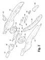
- FIG. 2is an exploded view of a proximal end of the exemplary laparoscopic device of FIG. 1 .
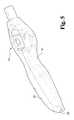
- FIG. 3is an elevated perspective view of the proximal end of the exemplary laparoscopic device of FIG. 2 , without the left side housing.
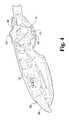
- FIG. 4is an elevated perspective view of the proximal end of the exemplary laparoscopic device of FIG. 2 , without the right side housing.
- FIG. 5is an elevated perspective view of the right and left side housings mounted to one another.
- FIG. 6is an underneath perspective view of the right and left side housings mounted to one another.
- FIG. 7is an elevated perspective view of an exemplary wheel of the exemplary laparoscopic device of FIG. 1 .
- FIG. 8is a profile view of the exemplary wheel of FIG. 7 .
- FIG. 9is an underneath perspective view of the exemplary wheel of FIG. 7 .
- FIG. 10is a bottom view of the exemplary wheel of FIG. 7 .
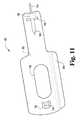
- FIG. 11is an elevated perspective view from the right side of an exemplary link plate of the exemplary laparoscopic device of FIG. 1 .
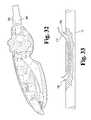
- FIG. 12is an elevated perspective view from the left side of the exemplary link plate of FIG. 11 .
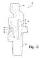
- FIG. 13is an elevated perspective view from the front of the exemplary link plate of FIG. 11 .
- FIG. 14is a magnified profile view, with the right side housing removed, showing the interaction between a wheel and a link plate at a first position.
- FIG. 15is a magnified profile view, with the right side housing removed, showing the interaction between a wheel and a link plate at a second position.
- FIG. 16is a magnified profile view of a wheel and link plate, with the right side housing removed, showing the interaction between a wheel and a link plate at a third position.
- FIG. 17Ais a profile view showing three vertical positions of the end effector achieved using an active repositioning mechanism.
- FIG. 17 Bis an overhead view showing three horizontal positions of the end effector (shown using changes in position of the semi-rigid conduit with respect to the end effector) achieved using a passive repositioning mechanism.
- FIG. 18is a magnified profile view, with the right side housing removed, showing an angle ⁇ between the catch and the trench.
- FIG. 19is an elevated perspective view of the outside of the right side housing of the exemplary laparoscopic device of FIG. 1 .
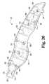
- FIG. 20is an elevated perspective view of the inside of the right side housing of the exemplary laparoscopic device of FIG. 1 .
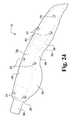
- FIG. 21is an elevated perspective view of the outside of an exemplary lever of the exemplary laparoscopic device of FIG. 1 .
- FIG. 22is a profile view of the exemplary lever of FIG. 21 .
- FIG. 23is an elevated perspective view of the inside of the exemplary lever of FIG. 21 .
- FIG. 24is an elevated perspective view of the outside of the left side housing of the exemplary laparoscopic device of FIG. 1 .
- FIG. 25is an elevated perspective view of the inside of the right side housing of the exemplary laparoscopic device of FIG. 1 .
- FIG. 26is a magnified profile view of an interior of a proximal portion of the exemplary controller of the laparoscopic device of FIG. 1 , with the left side housing removed.
- FIG. 27is a magnified profile view of an interior of a proximal portion of the exemplary controller of FIG. 1 , with the right side housing removed.
- FIG. 28is an elevated perspective view of an exemplary handle mechanism of the laparoscopic device of FIG. 1 .
- FIG. 29is an underneath perspective view of the exemplary handle mechanism of FIG. 28 .
- FIG. 30is an elevated perspective view of the interior of the exemplary controller and proximal portion of the conduit of the exemplary laparoscopic device of FIG. 1 , with the left side housing removed.
- FIG. 31is an elevated perspective view of the interior of the exemplary controller and proximal portion of the conduit of the exemplary laparoscopic device of FIG. 1 , with the right side housing removed and an exemplary cap installed.
- FIG. 32is an elevated perspective view of the interior of the exemplary controller and proximal portion of the conduit of the exemplary laparoscopic device of FIG. 1 , with the right side housing removed and an exemplary cap removed.
- FIG. 33is a longitudinal cross-sectional view of an alternate exemplary conduit for use with the laparoscopic device of FIG. 1 .
- FIG. 34is an exploded view of the distal end of the exemplary laparoscopic device of FIG. 1 .
- FIG. 35is an elevated perspective view of an exemplary clevis of the exemplary laparoscopic device of FIG. 1 .
- FIG. 36is an elevated perspective view of an exemplary clevis of FIG. 35 , without the top housing.
- FIG. 37is an overhead view of an exemplary clevis of FIG. 36 .
- FIG. 38is an elevated perspective view of a bottom housing of the exemplary clevis of FIG. 35 .
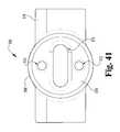
- FIG. 39is an elevated perspective view of an exemplary tooth receiver of the exemplary laparoscopic device of FIG. 1 .
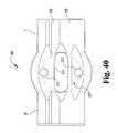
- FIG. 40is a front, profile view of the exemplary tooth receiver of FIG. 39 .
- FIG. 41is a rear, profile view of the exemplary tooth receiver of FIG. 39 .
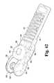
- FIG. 42is an elevated perspective view of an exemplary clevis of FIG. 35 , without the top housing, and with a pair of toothed plates and pelvis halves.
- FIG. 43is an elevated perspective view of an exemplary clevis of FIG. 35 , without the top housing, and with single toothed plate and single pelvis half
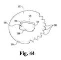
- FIG. 44is an elevated perspective view of an exemplary toothed plate of the exemplary laparoscopic device of FIG. 1 .
- FIG. 45is an outside profile view of an exemplary pelvis half of the exemplary laparoscopic device of FIG. 1 .
- FIG. 46is a front profile view showing the pelvis halves of FIG. 42 assembled.
- FIG. 47is an overhead view of the pelvis halves of FIG. 46
- FIG. 48an inside elevated perspective view of an exemplary pelvis half of the exemplary laparoscopic device of FIG. 1 .
- FIG. 49is an elevated perspective view of an exemplary repositionable jaw assembly of the exemplary laparoscopic device of FIG. 1 .
- FIG. 50is an elevated perspective view of an exemplary yoke and pull link of the exemplary laparoscopic device of FIG. 1 .
- FIG. 51is an elevated perspective view from the proximal end of the exemplary yoke of FIG. 50 .
- FIG. 52is a horizontal cross-sectional view of the exemplary yoke and pull link of FIG. 50 .
- FIG. 53is a horizontal cross-sectional view of the exemplary yoke of FIG. 50 .
- FIG. 54is an elevated perspective view of the pull link of FIG. 50 .
- FIG. 55is a horizontal cross-sectional view of the exemplary yoke and pull link coupled to exemplary link plates and link clips.
- FIG. 56is an elevated perspective view of the exemplary pull link coupled to exemplary link plates and link clips.
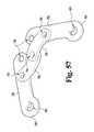
- FIG. 57is an elevated perspective view of the exemplary link plates coupled to the exemplary link clips of FIG. 56 .
- FIG. 58is an outside perspective view of an exemplary left side jaw of the exemplary laparoscopic device of FIG. 1 .
- FIG. 59is an inside perspective view of the exemplary left side jaw of FIG. 58 .
- FIG. 60is an overhead view showing the position of the jaws and various other distal end components of the exemplary laparoscopic device of FIG. 1 in a most compact widthwise orientation.
- FIG. 61is an overhead, magnified view of the jaws and link clips of FIG. 60 .
- FIG. 62is an overhead view showing the position of the jaws and various other distal end components of the exemplary laparoscopic device of FIG. 1 as the pull link is initially moved proximally.
- FIG. 63is an overhead, magnified view of the jaws and link clips of FIG. 62 .
- FIG. 64is an overhead view showing the position of the jaws and various other distal end components of the exemplary laparoscopic device of FIG. 1 as the pull link is moved farther proximally that in FIG. 62 .
- FIG. 65is an overhead, magnified view of the jaws and link clips of FIG. 64 .
- FIG. 66is an overhead view showing the position of the jaws and various other distal end components of the exemplary laparoscopic device of FIG. 1 as the pull link is moved to its most proximal position to fully open the jaws.
- FIG. 67is an overhead view showing the position of the jaws and various other distal end components if the exemplary laparoscopic device of FIG. 1 did not include a pivot point between the jaws and link clips.
- FIG. 68is a perspective view of an exemplary clamp in an open position that may be used with the exemplary laparoscopic device of FIG. 1 .
- FIG. 69is a perspective view of the exemplary clamp of FIG. 68 in a closed position.
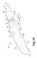
- FIG. 70is a cross-sectional view of the exemplary clamp of FIG. 68 in its open configuration, showing the wire member, rigid tubular members, and the urging members.
- FIG. 71is a cross-sectional view of the exemplary clamp of FIG. 69 in its closed configuration, showing the wire member, rigid tubular members, and the urging members.
- FIG. 72is a perspective view of the exemplary claims of FIGS. 68-71 and showing the ability to close in a non-parallel fashion.
- FIG. 73is a perspective view of the first stage of assembly of an alternate embodiment of a clamp, showing a wire member surrounded by rigid tubular members.
- FIG. 74is a perspective view of the second stage of assembly of the clamp of FIG. 73 , in which platens have been added over the rigid tubular members.
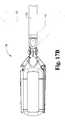
- FIG. 75is a perspective view of the clamp of FIGS. 73 and 74 , once an outer fabric covering has been disposed over the entire surface of the clamp.
- FIG. 76is an elevated perspective view of an alternate exemplary controller that may be used with the laparoscopic device of FIG. 1 .
- FIG. 77is an elevated perspective view of the alternate exemplary controller of FIG. 76 , shown without the left side housing.
- FIG. 78is a magnified, perspective view of the interior of a distal portion of the alternate exemplary controller of FIG. 76 .
- FIG. 79is a profile view of the structure shown in FIG. 78 with the button shown in its highest vertical position.
- FIG. 80is a profile view of the structure shown in FIG. 78 with the button shown depressed in its lowest vertical position.
- FIG. 81is a magnified, perspective view of the interior of a distal portion of the alternate exemplary controller of FIG. 76 , shown without the button and first toothed assembly.
- FIG. 82is a magnified, perspective view of the interior of a distal portion of the alternate exemplary controller of FIG. 76 , shown without the button.
- the exemplary embodiments of the present disclosureare described and illustrated below to encompass surgical equipment and, more specifically, to surgical equipment that may be used in minimally invasive procedures.
- the disclosurealso relates to surgical equipment to facilitate the positioning and deployment of an atrial appendage occlusion device.
- the disclosurerelates to surgical equipment that is adapted to accommodate or work in tandem with flexible endoscopes.
- the embodiments discussed beloware exemplary in nature and may be reconfigured without departing from the scope and spirit of the present disclosure.
- the exemplary embodiments as discussed belowmay include optional steps, methods, and features that one of ordinary skill should recognize as not being a requisite to fall within the scope of the present disclosure.
- an exemplary laparoscopic device 100comprises a controller 110 mounted to a proximal portion of a semi-rigid conduit 112 that is relatively linear.
- the controller 110includes various controls in order to manipulate a repositionable mechanism 116 operatively coupled to an end effector 118 , where the repositionable mechanism is mounted to a distal portion of the conduit 112 .
- the repositionable mechanism 116is coupled to an end effector comprising a clip deployment device 118 .
- the end effector 118may comprise any number of devices such as, without limitation, forceps, ablation rails, jaws, linear cutters, ablation pens, ablation clamps, illuminated dissectors, and non-illuminated dissectors.
- the exemplary repositionable mechanism 116incorporates an active mechanism and a passive mechanism. It should be noted that the active mechanism is operative to control the pitch (i.e., up and down) of the end effector 118 , while the passive mechanism is operative to control the yaw (i.e., side to side) of the end effector. However, as will be evident from the following disclosure, the repositionable mechanism 116 in an alternate exemplary embodiment may comprise only active or passive mechanisms.
- the repositioning mechanism 116 in further alternate exemplary embodimentsmay utilize a passive mechanism to control the pitch (i.e., up and down) of the end effector 118 , while an active mechanism is operative to control the yaw (i.e., side to side) of the end effector.
- a passive mechanismto control the pitch (i.e., up and down) of the end effector 118
- an active mechanismis operative to control the yaw (i.e., side to side) of the end effector.
- the controller 110comprises a right side housing 130 and a left side housing 132 that cooperatively define an internal cavity and corresponding openings to accommodate throughput of certain controls.
- a first of these openingsis a dorsal opening 134 that accommodates throughput of a pair of wheels 136 , 138 that are rotationally repositionable along a lateral axis.
- each wheel 136 , 138includes a contact face 140 adapted to be contacted by a user in order to rotate the wheel.
- the contact face 140includes a series of circumferentially distributed depressions 142 interposed by a series of knurls 144 to facilitate grip between the user and the wheel 136 , 138 .
- Each knurl 144is sloped to match the contour of the wheel 136 , 138 , which decreases from a maximum where the contact face 140 abuts an interior face 146 .
- Radially inset from the depressions 142 and the knurls 144is a planar ring surface 148 that circumferentially delineates the outer boundary of a ring-shaped exterior cavity 152 .
- a pair of sloped surfaces 154 , 156 inset from the ring surface 148 and axially spaced from one anotheroperate to constrict the diameter of the cavity 152 when moving axially, deeper into the cavity.
- the cavity 152is also partially delineated by a hollow axle 158 that extends from the center of each wheel 136 , 138 .
- This axle 158is circumferentially surrounded at its base by a circular plateau 162 , where the axle and plateau cooperate to incrementally increase the radial dimension of the ring-shaped cavity 152 .
- An interior of the axle 158defines a cylindrical cavity 166 that continues this cylindrical shape until reaching an interior midpoint where the cavity takes on a semicircular shape that extends through to the interior surface 146 .
- a semicircular projection 170 adjacent to the cavity 166extends generally perpendicularly away from the interior surface 146 .
- the interior surface 146also includes a spiral trench 172 that is distributed approximately two hundred and twenty degrees around the projection 170 . In this manner, the radial distance between the trench 172 and the projection 170 gradually changes until reaching a maximum and minimum at the ends of the trench.
- each wheel 136 , 138is operatively coupled to the repositionable mechanism 116 and operate to control pitch of the repositionable mechanism.
- each wheel 136 , 138is coupled to a link plate 180 that converts the rotational motion of the wheel into longitudinal motion along a longitudinal axis extending along the length of the conduit 112 .
- each link plate 180comprises a key shape having a planar section 182 and a plurality of stamped openings 184 , 186 , 188 .
- the first of these stamped openings 184has a horseshoe shape that creates a projection extending into the opening.
- the second opening 186has a generally oval shape with circular ends and is provided in order to reduce the weight of the link plate 180 and provide a complementary opening for the semicircular projection 170 of a corresponding wheel 136 , 138 (see FIGS. 8-10 ).
- the third opening 188has a widthwise dimension that is substantially shorter than the vertical dimension to create an elongated, generally rectangular opening with rounded corners. This third opening 188 provides a throughput for a connection wire 194 and cooperates with a half-loop 196 to secure the connection wire to the link plate 180 .
- connection wire 194is threaded on the interior (i.e., concave aspect of the half-loop) of the half loop and extends through the third opening 188 .
- the connection wire 194includes a cylindrical sleeve 198 that is secured to the wire so that lateral movement between the sleeve and wire does not occur.
- the sleeve 198is dimensioned to allow for throughput of the sleeve and connection wire 194 through the third opening 188 .
- each link plate 180also includes a spacer flange 200 that extends above the second opening 186 .
- the spacer flange 200comprises a longitudinal S-shape bend that is applied to the top of the key-shape. This flange 200 cooperates with a counterpart flange 200 of another link plate 180 to ensure proper spacing between adjacent link plates.
- assembly of the wheels 136 , 138 and link plates 180provides for a means for repositioning the repositionable mechanism 116 upward or downward simply by rotating the wheels in a clockwise or counterclockwise direction.
- the link plates 180are assembled back to back, with one of the link plates 180 being inverted, so that the flanges 200 face inward toward one another.
- the flange 200 of a first link plate 180abuts the planar surface 182
- the second link plate flange 200abuts the planar surface 182 of the first link plate.
- the catches 190 of each link plate 180extend outward, away from one another.
- the catches 190(and a portion of the link plates 180 themselves) are sandwiched between the interior faces 146 of the wheels 136 , 138 and are received within a respective spiral trench 172 of the adjacent wheel 136 , 138 .
- semicircular projections 170 of the wheels 136 , 138are aligned so that the planar surfaces of the projections abut one another, thereby forming a cylindrical projection that extends through both second openings 186 of the link plates 180 .
- rotation of the wheels 136 , 138 in concertis operative to change the vertical orientation of the repositionable mechanism 116 .
- rotation of the wheels 136 , 138 from the topmoving distally and downward, is operative to pull the first link plate 180 proximally, while pushing the second link plate distally.
- the rotational motion of the wheels 136 , 138via the interface between the spiral trench 172 and the catches 190 , is transformed into horizontal motion of the link plates 180 .
- the catch 190 of the first link plate 180abuts an end of the spiral trench 172 of the first wheel 136 that operates to limit the vertical travel of the repositionable mechanism 116 .
- the vertical travelis limited so that the maximum angle of deflection is negative sixty degrees from horizontal.
- the wheels 136 , 138are rotated clockwise, thereby changing the position of the spiral trench 172 with respect to the catch 190 .
- the catch 190rides within the spiral trench 172 and is maintained in a constant horizontal orientation with respect to the trench because of the tension of the connection wire 194 pulling on the link plate 180 proximally.
- the rotation of the wheels 136 , 138is proportional to the pivoting motion of the repositionable mechanism 116 .
- position Ccorresponds to the catch 190 being adjacent the opposite end of the spiral trench 172 , which is operative to set the vertical travel limit of sixty degrees from horizontal.
- the wheels 136 , 138are operative to convert three degrees of rotational motion into one degree of pivoting motion.
- shape of the spiral trench 172may be modified to increase or decrease the conversion between rotational motion of the wheels 136 , 138 to pivoting motion of the repositionable mechanism 116 .
- the pitch of the spiral trench 172may set so that two full rotations of the wheels 136 , 138 are necessary to move from one endpoint to the opposite endpoint of the trench.
- the conversionwould be six degrees of rotational motion translating into one degree of pivoting motion (presuming the maximum pivoting range was 120 degrees).
- the pitch of the spiralmay be set to extend around one third of the wheels 136 , 138 so that the conversion would be one to one (i.e., one degree of rotational motion translates into one degree of pivoting motion).
- the spiral trench 172can also be set to have variable rates as the wheels 136 , 138 are turned. In other words, the distance changes from the center of the wheels 136 , 138 to the trench 172 is not constant along all 360 degrees.
- the middle section of the trench 172may have a pitch that correlates to two degrees of rotation being converted into one degree of pivotal motion of the repositionable mechanism 116 within ⁇ 20 degrees from horizontal (i.e., zero degrees). But beyond this point, the trench 172 pitch is decreased so that the final 40 degrees of travel (between 20 to 60 degrees and ⁇ 60 to ⁇ 20 degrees) is achieved by turning the wheels three degrees to achieve one degree of pivotal motion.
- the pitch of the trench 172and having one or more trench sections with different pitches.
- the pitch (i.e., angle ⁇ ) of the spiral trench 172also influences whether the repositioning mechanism 116 is self-locking.
- self-lockingrefers automatically inhibiting movement.
- the resistance to movement of the catch 190 within the trench 172decreases.
- the angle ⁇ between the catch and trenchis ninety degrees
- resistanceis maximized.
- the angle ⁇ between the catch and trenchis zero
- the resistanceis minimized.
- the resistanceis great enough to provide a self-locking feature.
- the resistance to movement of the catch 190 within the trench 172must be greater than the tensile force T on the connection wire 194 .
- the more spiral turns that comprise the trench 172the greater the angle ⁇ .
- the less spiral turns that comprise the trench 172the lesser the angle ⁇ and the greater the chance of a back load causing the wheels 136 , 138 to rotate.
- the spiral trench 172has an angle of approximately 80-85 degrees.
- This angleis sufficient to provide a self-locking feature so that a back load (a force applied directly to the repositioning mechanism 116 that is transmitted along the connection wire 194 ) is inoperative to cause the wheels 136 , 138 to rotate, thereby inhibiting pivoting motion of the repositioning mechanism.
- a back loada force applied directly to the repositioning mechanism 116 that is transmitted along the connection wire 194
- connection wires 194are mounted to the yoke 614 that rotates with respect to the pelvis halves 594 , 596 in order to provide an infinite number of positions within the range of motion afforded by the spiral trench 172 of the wheels 136 , 138 .
- this mechanismis referred to as an active repositioning mechanism because it is the affirmative rotation of the wheels that directly results in a proportional movement of the yoke 614 with respect to the pelvis halves 594 , 596 .
- a user of the wheels 136 , 138is operative to lock the position of the end effector 118 simply by discontinuing rotation of the wheels.
- the resistance to rotation of the wheels 136 , 138is the result of the angle between the trench 172 boundaries and the catch 190 of the link plates 180 .
- a user of the wheels 136 , 138actively controls the position of the end effector 118 .
- the active mechanismmay be remotely controlled so that a user does not physically touch the wheels 136 , 138 , but instead operates a controller remote from the wheels.
- the controlleris in communicatively coupled to a motor or actuator operative to drive the wheels in the desired direction, thereby allowing remote control of the wheels.
- the active mechanismis removed from the controller 110 and repositioned distally at the distal end of the conduit 112 , proximate the end effector 118 .
- the active mechanismis exposed and available to be manipulated by a robotic appendage, thereby repositioning the end effector locally (with respect to the controller 110 ). More specifically, the wheels would be rotated by the robotic appendage in order to reposition the end effector 118 .
- this active mechanismis in contrast to a passive mechanism having “on” and “off” functionality that allows certain movement of the end effector 118 or disallows this same movement. Because the mechanism does not affirmatively allow control of incremental motion of the end effector 118 , but rather only operates to allow or disallow motion, the mechanism is referred to herein as passive.
- the right side housing 130 of the controller 110also includes an exterior depression 230 and a pair of through openings 232 , 234 to accommodate a repositionable lever 236 that is part of the passive mechanism.
- the repositionable lever 236may be manipulated to lock and unlock the repositionable mechanism 116 in order to provide for or constrain lateral adjustability of the end effector 118 .
- the first through opening 232is defined by a cylindrical bearing 238 that extends perpendicularly away from the housing 130 .
- the bearing 238includes an exterior circular bearing surface 240 and an interior circular bearing surface 242 that are sandwiched by the lever 236 .
- the lever 236rotates around the exterior bearing surface 240 and rotates within the interior bearing surface 242 .
- the lever 236includes a tapered appendage 248 integrally formed with a cupped cover 250 .
- An interior of the cupped cover 250is hollowed to define an internal cavity 252 delineated by a peripheral wall 254 having a generally circular shape at one end and an arcuate shape (but not rounded) at the other end.
- a cylindrical upstanding projection 256extends perpendicularly away from the interior of the cupped cover 250 and is generally equidistantly spaced from the circular portion of the peripheral wall 254 , but extends above the height of the peripheral wall.
- a second cylindrical upstanding projection 258is formed at a corner of the arcuate end of the peripheral wall 254 .
- This second cylindrical projection 258extends perpendicularly away from the interior of the cupped cover 250 (and parallel to the first cylindrical projection 256 ) and extends above the height of the first cylindrical projection 256 .
- the first cylindrical projection 256is received within the first through opening 232 of the cylindrical bearing 238
- the second cylindrical projection 258is received within the second through opening 234 .
- the circular cross-section of the first cylindrical projection 256 and the first through opening 232 and the dimensions of eachallow for rotation of the rotation of the first cylindrical projection within the first through opening without significant radial play that would otherwise cause the lever 236 to not consistently rotate around a single rotational axis.
- the second through opening 234is elongated and takes on an arcuate path that tracks the movement of the second cylindrical projection 258 . More specifically, the second through opening 234 includes rounded ends that generally match the curvature and dimensions of second projection 258 , but allow for play between the bounds of the opening and the projection so the projection can move within the opening. At the same time, the height of the second through opening 234 is slightly larger than the diameter of the second projection 258 , while the arcuate path of the through opening tracks the position of the second projection as the lever 236 rotates about the housing 130 . The bounds or endpoints of the opening 234 provide a limit on the rotational repositioning of the lever 236 .
- the boundsprovide a locked and an unlocked position that corresponds to locked or free lateral adjustability of the end effector 118 .
- the lever 236is coupled to a connection wire 261 by winding the connection wire around the first cylindrical projection 256 .
- the remaining exterior surface 260 of the right side housing 130is convex and includes a number of additional features.
- the additional featuresinclude an enlarged section 264 , proximate a distal end 262 , which is rounded on its underside.
- This enlarged section 264tapers proximally and distally to transition into a proximal neck 266 and a distal flange 268 .
- the distal flange 268interposes the enlarged section 264 and a semi-circular adapter 270 .
- the adapter 270includes a pair of detents 272 that engage the semi-rigid conduit 112 in order to inhibit longitudinal movement of the conduit with respect to the controller 110 .
- Both detents 272extend in parallel to one another and extend from an interior circumferential surface 278 of the adapter 270 that communicates with an exterior of the semi-rigid conduit 112 .
- the exterior of the adapter 270is smooth and semicircular in order to receive a cylindrical cap 282 that circumscribes the exterior of the adapter 270 .
- the exterior surface 260 of the right side housing 130also includes a sloped dorsal surface 284 (sloped downward from distal to proximal) that arcuately transitions into a sculpted recess 286 and a bowed medial surface 288 that both transition to a relatively planar ventral surface 290 .
- the ventral surface 290 of the right side housing 130cooperates with a corresponding ventral surface 294 of the left side housing 132 to partially delineate a handle mechanism port 296 and a handle retention port 298 . Both ports 296 , 298 are open to the interiors of the respective housings 130 , 132 .
- the surfaces 284 , 288 , 290converge at the proximal end to partially define a proximal port 300 that is also open to the interior of the housing 130 .
- the interior of the right side housingincludes a series of hollow cylinders 304 that extend generally perpendicularly from the interior surface and are generally parallel to one another.
- Each cylinder 304is sized to receive a threaded fastener in order to mount the respective housings 130 , 132 to each other.
- two of the hollow cylinders 304are spaced apart from one another by a cross-member 306 having a semicircular cutout.
- Extending proximally from these hollow cylinders 304is a pair of stiffening ribs 308 that are partially interposed by a projection 310 having a corresponding shape that defines the exterior depression 230 .
- the projection 310At the proximal end of the projection 310 are another pair of hollow cylinders 304 . These hollow cylinders 304 are followed by another pair of stiffening ribs 308 that interpose a third set of hollow cylinders 304 . This pair of hollow cylinders 304 comprising the third set is spaced apart from one another by a cross-member 312 that includes an oblong projection 314 extending proximal-to-distal. As will be discussed hereafter, the oblong projection 314 is hollowed and includes a corresponding cavity 316 that receives a portion of the handle mechanism 320 (see FIG. 26 ).
- a proximal stiffening rib 308interposes the third set of cylinders and a proximal single cylinder 304 .
- a portion of the perimeter of the interior surface of the right side housing 130includes a recessed ledge 322 that is received within a corresponding channel 324 (see FIG. 25 ) of the left side housing 132 in order to align the housings 130 , 132 .
- the interior of the right side housingalso includes a detent 326 that extends into the handle retention port 298 and is used to retain the handle mechanism in a set position.
- the left side housing 132is similar to the right side housing 130 and includes a convex exterior surface 340 and a concave interior surface 342 .
- the interior and exterior surfaces 340 , 342converge to partially define the dorsal opening 134 , the handle mechanism port 296 , the handle retention port 298 , and the proximal port 300 .
- the left side housing 132 of the controller 110includes an enlarged section 354 , proximate a distal end 352 that is rounded on its underside.
- This enlarged section 354tapers proximally and distally to transition into a proximal neck 356 and a distal flange 358 .
- the distal flange 358interposes the enlarged section 354 and a semi-circular adapter 360 .
- the exterior of the adapter 360is smooth and semicircular in order to receive the cylindrical cap 282 that circumscribes the exterior of the adapter 360 .
- the exterior surface 340 of the left side housing 132also includes a sloped dorsal surface 364 (sloped downward from distal to proximal) that arcuately transitions into a sculpted recess 366 and a bowed lateral surface 368 that both transition to a relatively planar ventral surface 294 .
- the bowed lateral surface 368includes a plurality of through holes 370 that are partially bounded by corresponding hollow cylinders 372 that extend into the interior of the left side housing 132 .
- These cylinders 372are adapted to be aligned with the hollow cylinders 304 of the right side housing 130 and receive corresponding fasteners (not shown) in order to mount the housings to each other.
- ventral surfaces 290 , 294 of the housings 130 , 132cooperate to delineate the handle mechanism port 296 and the handle retention port 298 .
- the surfaces 364 , 368 , 294converge at the proximal end to partially define the proximal port 300 that is also open to the interior of the housing 132 .
- the interior of the left side housing 132includes several hollow cylinders 372 that extend generally perpendicularly from the interior surface 342 and are generally parallel to one another.
- two of the hollow cylinders 372 nearest the distal endare spaced apart from one another and have generally the same height.
- Traveling proximally from these hollow cylinders 372is a pair of stiffening ribs 378 that are partially interposed by a cylindrical projection 380 having a hollow interior cavity 382 and a longitudinal height approximating the height of the ribs.
- Traveling proximally from the stiffening ribs 378are a pair of hollow cylinders 372 that are spaced apart from one another by an L-shaped cross-member 383 .
- the dorsal cylinder 372has a height relatively the same as the height of the tall portion of the cross-member, while the ventral cylinder has a height relatively the same as the height of the lower portion of the cross-member.
- a larger hollow cylinder 384intersects a stiffening rib 379 having a notch cut out of it to resemble the L-shaped cross-member.
- an L-shaped cross-member 385Further traveling proximally from the larger cylinder 384 is an L-shaped cross-member 385 , followed by a pair of hollow cylinders 372 comprising a third set spaced apart from one another by a cross-member 386 that includes an oblong projection 388 extending proximal-to-distal.
- the oblong projection 388is hollowed and includes a corresponding cavity 390 that receives a portion of the handle mechanism 320 .
- a proximal stiffening rib 392interposes the third set of cylinders and a proximal single cylinder 394 .
- a portion of the perimeter of the interior surface 340 of the left side housing 132includes channels 324 that receive the recessed ledge 322 of the right side housing 130 .
- the handle mechanism 320comprises a repositionable handle 400 , a drive link 402 , a return spring 404 , and a draw plate 406 .
- the draw plate 406is coupled to a draw wire 408 operatively coupled to the clip deployment device 118 in order to selectively open and close an occlusion clip 1160 (see FIG. 75 ), such as during an atrial appendage occlusion clip deployment surgical procedure.
- the repositionable handle 400includes an arcuate, ventral gripping surface 414 having a series of convex bumps 416 longitudinally spaced apart to facilitate gripping by a user.
- the ventral gripping surface 414tapers in the medial-to-lateral direction from a maximum in between the proximal and distal ends.
- Opposite the ventral gripping surface 414is a corresponding interior surface 418 from which a pair of spaced apart, parallel vertical walls 420 , 422 extend.
- the vertical walls 420 , 422are also connected to one another via a plurality of cross walls 424 .
- the proximal cross wallis also connected to an upstanding loop 428 that provides a through opening 430 in the medial-to-lateral direction.
- the walls 420 , 422Extending distally from the loop 428 , the walls 420 , 422 gradually increase in height and extend distally beyond the ventral gripping surface 414 .
- the distal most portion of the walls 420 , 422each includes a rounded, dorsal end having a circular opening 434 extending in the medial-to-lateral direction.
- a distal wall 436spans between the walls 420 , 422 at the distal end and transitions into the ventral gripping surface 414 .
- the circular openings 434 of the walls 420 , 422are laterally aligned, as are two other pairs of circular openings 440 , 442 extending through the walls in the medial-to-lateral direction.
- Both paired openings 440 , 442are smaller in diameter than the distal openings 434 and each is adapted to receive a pin 444 in order to repositionably mount the drive link 402 to the handle 400 . While only one of the paired openings 440 , 442 will be occupied by the pin 444 , the other paired opening unoccupied may be used depending upon the spring rate of the return spring 404 and the device (e.g., clip deployment device 118 ) comprising the end effector 118 .
- An exemplary drive link 402comprises a U-shaped, longitudinally extending plate sized to fit between the walls 420 , 422 of the handle 400 .
- a distal end of the plate 402includes the U-shaped bend and a pair of through openings (extending in a medial-to-lateral direction) that receive the pin 444 .
- a proximal end of the plate 402includes respective legs in parallel to one another and each having a through opening. Each of the legs of the plate 402 is biased by the coiled return spring 404 , which contacts the rounded end of each leg.
- the return spring 404is not rigidly coupled to the drive link 402 , but rather is biased against the drive link and retained in position by the bias of the return spring itself pushing against respective stiffening ribs of the housings 130 , 132 and the proximal ends of the plate 402 .
- the through openings in the legsreceive a second pin 450 , which is also concurrently received within the cavity 390 of the oblong projection 388 and within the cavity 316 of the oblong projection 314 , that couples the drive link 402 to the draw plate 406 .
- the draw plate 406comprises a substantially straight and flat substrate having three openings 460 , 462 , 464 that extend in the medial-to-lateral direction.
- the first opening 460receives the second pin 450 to mount the drive link to the draw plate 406 .
- the second opening 462comprises a rectangular opening with rounded corners, while the third opening 464 comprises a smaller rectangular opening with rounded corners having a proximal-to-distal dimension that is less than the dorsal-to-ventral dimension.
- a strip of the draw plate 406interposes the openings 462 , 464 and is deformed to create a lateral half loop 468 concave laterally and convex medially.
- a second strip of the draw plate 406 at the distal endis also deformed to create a medial half loop 470 convex laterally and concave medially.
- the lateral half loop 468is deeper than the medial half loop 470 because the lateral half loop 468 is sized to accommodate a sleeve 474 that circumscribes a proximal portion of the draw wire 408 .
- This sleeve 474is not readily repositionable longitudinally along the draw wire 408 . Accordingly, repositioning of the sleeve 474 while the draw wire 408 is in tension correspondingly causes the draw wire to be repositioned.
- the repositionable handle 400is adapted to be grasped by a user and repositioned from a retained position to a free position.
- the loop 428 of the handle 400engages the detent 326 of the right side housing 130 to retain the handle adjacent to the housings 130 , 132 .
- the bias of the spring 404is operative to push against the drive link 402 , which itself pushes against the handle 400 to force the handle away from the housings 130 , 132 .
- the draw plate 406is also repositioned.
- the draw plate 406When the handle 400 engages the detent 326 , the draw plate is fully retracted in a proximal-most position. As will be discussed in more detail hereafter, the proximal-most position of the draw plate 406 results in the draw wire 408 , which is also mounted to the pull link 764 , being pulled proximally to open the occlusion clip 1160 . Conversely, when the handle 400 disengages the detent 326 and is moved away from the housings 130 , 132 , the draw plate is repositioned in a distal direction. Eventually, if the handle 400 is repositioned to the maximum travel away from the housings 130 , 132 , the draw plate 406 is positioned in a distal-most position. As will be discussed in more detail hereafter, the distal-most position of the draw plate 406 results in the draw wire 408 repositioned distally in order to close the occlusion clip 1160 .
- the controller 110also includes a removable stem 490 that is seated within the proximal port 300 of the housings 130 , 132 .
- the removable stem 490is coupled to one or more clip release wires 492 (in this case, two clip release wires) that act to disconnect an occlusion clip from the clip deployment device 118 .
- the stemmay be removed from the proximal end of the controller 110 , thereby drawing the release wire(s) proximally and disconnecting the occlusion clip from the clip deployment device 118 .
- the stem 490is secured within the proximal port 300 via a friction fit that may be overcome by the user applying pressure to the stem to move it proximally with respect to the controller 110 . But it is also within the scope of the disclosure to use detents or other affirmative release mechanisms to release the stem 490 from the controller 110 .
- assembly of the controller 110includes mounting the wheels 136 , 138 to one another so that the interior faces 146 of the wheels sandwich the link plates 180 therebetween.
- a detailed discussion of assembly of the wheels 136 , 138 and link plates 180has already been provided and will not be repeated for purpose of brevity.
- the wheels 136 , 138are oriented so that the axles 158 face in opposite directions and are received respectively within the cylindrical projection 380 of the left side housing 132 and within the circular bearing surface 242 of the right side housing 130 .
- the drive link 402is mounted to the right and left side housings 130 , 132 by way of the pin 450 concurrently received within the cavities 316 , 390 of the oblong projections 314 , 388 .
- the drive link 402 and right side housing 130sandwich the draw plate 406 therebetween.
- the drive link 402is mounted to the handle 400 , while the circular opening 434 of the handle receives a cylinder 304 of the right side housing 130 in order to rotationally mount the handle to the housing.
- the spring 404is inset within the right side housing 130 so that the spring interposes the proximal stiffening rib 308 and the drive link 402 .
- the removable stem 490is inserted between the housings 130 , 132 and thereafter, the housings 130 , 132 are mounted to one another to close the controller.
- the draw wire 408 , the clip release wires 492 , the connection wires 194 , and the connection wire 261all extend through the distal end 262 of the housings 130 , 132 .
- the controller 110is mounted to a semi-rigid conduit 112 that is relatively linear and has a relatively constant circular cross section.
- the conduit 112is fabricated from stainless steel and includes a proximal circular opening and a distal circular opening.
- the proximal circular openingprovides access between the interior of the conduit 112 and the interior of the controller 110 . More specifically, the hollow interior of the conduit 112 accommodates throughput of the draw wire 408 , the clip release wires 492 , the connection wires 194 , and the connection wire 261 .
- the conduit 112includes a proximal section having a pair of rectangular, arcuate cut-outs 500 . These cutouts 500 provide respective openings for the detents 272 of the adapter 270 to occupy and mount the conduit 112 to the housings 130 , 132 .
- the semi-rigid conduit 112may be relatively linear but include two additional orifices 504 , 506 that accommodate a separate conduit 508 adapted to provide a separate avenue for an exploratory tool 510 .
- Exemplary exploratory tools for use with the instant semi-rigid conduitinclude, without limitation, forceps, ablation rails, jaws, linear cutters, ablation pens, ablation clamps, illuminated dissectors, and non-illuminated dissectors.
- the exemplary exploratory tool 510may be used in combination with the end effector, which is manipulated by the repositionable mechanism 116 .
- a distal portion of the exemplary repositionable mechanism 116comprises a clevis 514 comprising ventral and dorsal clevis housings 516 , 518 .
- Each housing 516 , 518is a mirror image of the other and includes a convex, semi-cylindrical proximal section 522 having a partially enclosed semicircular proximal end 524 except for a notch 526 .
- the exterior surface of the semi-cylindrical proximal section 522includes a pair of through holes 530 extending into the interior of the housing that are generally longitudinally aligned and positioned to lie along the apex of the cylindrical proximal section 522 .
- a semi-cylindrical collar 532Extending longitudinally in a distal direction beyond the through holes 530 is a semi-cylindrical collar 532 operative to increase the diameter of the housing 516 , 518 in comparison to the cylindrical proximal section 522 that has a generally constant diameter.
- Extending distally from the collar 532is an overhang 536 .
- the overhang 536includes a generally planar exterior surface 538 that transitions into a sloped perimeter surface 540 embodying parallel sides with a rounded proximal end 542 .
- the perimeter surfaceadjoins a substantially planar interior surface 544 that is substantially in parallel with the planar exterior surface 538 .
- the interior surface 544includes a circular depression 546 and includes a circular circumferential surface 548 that extends between the interior surface and a bottom, planar surface 550 of the depression.
- the interior surfacealso includes a portion of a rectangular depression 552 that continues distally into a concave, semi-cylindrical interior surface 554 of the collar 532 .
- the semi-cylindrical interior surface 554 of the collar 532takes on the same dimensions as the semi-cylindrical interior surface of the cylindrical proximal section 522 .
- the semi-cylindrical interior surface 554 of the cylindrical proximal section 522includes a distal rib 558 having generally the same shape as the partially enclosed semicircular distal end 524 .
- the distal rib 558also includes a notch 560 that is longitudinally aligned with the other notch 526 so that the notches have generally the same dimensions.
- the distal ribs 558are aligned over one another so that the notches 560 , 526 cooperate to provide a pair of through openings.
- the distal ends 524 of the housingsare also aligned to create an internal cavity that houses a bias spring 564 and a tooth receiver 566 as part of the clevis 514 .
- the tooth receiver 566includes a proximal cylindrical portion 568 having a uniform circular cross-section and extending substantially linearly.
- the uniform circular cross-sectionis sized to be received within the bias spring 564 upon assembly.
- the proximal cylindrical portion 568is hollow and includes a circular proximal end wall 570 having a pair of circular openings 572 each adapted to accommodate throughput of the connection wires 194 .
- a larger, oblong opening 574interposes the circular openings 572 and is adapted to accommodate throughput of the draw wire 408 and the clip release wires 492 .
- a tooth receiving head 576Extending distally from the cylindrical portion 568 is a tooth receiving head 576 having medial M and lateral L sections that extend medially and laterally from the cylindrical portion. Interposing the medial and lateral sections is a cylindrical cavity 577 aligned with the hollow cavity of the proximal cylindrical portion 568 .
- Each section of the tooth receiving head 576includes a generally rectangular cross-section, but for a series of distal teeth 578 .
- the teeth 578have a sawtooth pattern and are formed to extend in the medial-to-lateral direction (perpendicular to a longitudinal axis extending through the cylindrical portion 568 ).
- the teeth 578are sized to receive respective teeth 580 from a pair of toothed plates 582 .
- each toothed plate 582is also part of the clevis 514 and each toothed plate 582 comprises a circular, generally flat plate. Approximately two hundred and twenty-five degrees of the plate has a circular circumferential surface 584 . But the remaining one hundred and thirty-five degrees of the circumferential surface is formed to include a series of teeth 580 . As discussed above, the teeth 580 are sized to be received in between the teeth 578 of the tooth receiver 566 . Centered within the middle of each toothed plate 582 is a through opening 586 delineated by parallel, linear sides 588 and arcuate ends 590 . These through openings 586 are adapted to receive a respective pelvis half 594 in order to allow or limit lateral movement of the pelvis half.
- assembling the clevis 514includes inserting the proximal cylindrical portion 568 of the tooth receiver 566 into the cylindrical cavity outlined by the spiral shape of the bias spring 564 . Assembling the clevis 514 also includes aligning the ventral and dorsal clevis housings 516 , 518 so that the edges where the exterior and interior surfaces meet match up and overlie each other. The edges may be welded or adhered together using conventional techniques. The resulting structure from assembly of the housings 516 , 518 creates a distal cylindrical cavity 598 and a proximal cylindrical cavity 600 that are interposed by a circular wall having a through opening.
- the circular wallis formed by joining the distal ribs 558 of the housings 516 , 518 , while the opening is formed by joining the notches 560 .
- the distal cylindrical cavity 598is sized to accommodate the tooth receiver 566 inserted into the bias spring 564 so that the end of the bias spring opposite the tooth receiver contacts the circular wall to provide a stop against which the spring may be compressed.
- distal end 524is closed off except for an opening formed by the adjoined notches 526 .
- the connection wire 261is operatively coupled to the lever 236 . This wire 261 also extends through the semi-rigid conduit 112 and through the openings until reaching the toothed receiver 566 , where the wire is mounted to the toothed receiver in order to facilitate repositioning of the toothed receiver.
- the clevis 514is coupled to a universal joint 610 .
- This universal joint 610comprises a first pelvis half 594 coupled to a second pelvis half 596 .
- the pelvis halves 594 , 596are coupled to the clevis 514 .
- the pelvis halves 594 , 596are identical to one another and, as such, a detailed explanation of only one of the pelvis halves is provided in furtherance of brevity.
- Each pelvis half 594 , 596includes a distal paddle 624 having a substantially planar interior surface 626 that circles an upstanding rim 628 .
- An opening 630extends through the rim 628 and through the paddle 624 , but is partially covered by an exterior convex cap 634 that is integrally formed with the paddle.
- the cap 634includes a V-shaped groove 636 that extends into the opening 630 on one side, and a channel 638 that extends into the opening from the opposite side.
- the channel 638extends proximally beyond the cap 634 and takes on an arcuate path to partially wrap around a proximal end 640 of the pelvis half and ends proximate an integrated platform 642 having a circular profile.
- a semi-circular interior surface 646 of the platform 642is substantially planar and includes a radial groove 648 with arcuate sidewalls and a rounded end that extends to the center of the platform.
- the arcuate sidewallsoperate to increase the width of the groove 648 as the distance from the interior surface 646 increases.
- the radial groove 648also extends outward through a circular circumferential surface 650 .
- the circumferential surface 650defines the outer bounds of a ring-shaped, planar outer surface 652 that circumscribes an upstanding projection 656 . It is this upstanding projection 656 that extends through the opening 586 of a corresponding toothed plate 582 to mount the tooted plate to the yoke half 620 (see FIG. 42 ).
- the upstanding projection 656extends perpendicularly away from the ring-shaped surface 652 and includes a pair of parallel straight sides 658 that are interposed by a pair of arcuate sides 660 that collectively define a plateau top 662 .
- the distal paddle 624includes a circular 664 circumferential surface connecting to a neck 666 in order to connect the distal paddle 624 to the integrated platform 642 .
- the neck 666also includes an arcuate wall 668 adapted to match the contour of the circular circumferential surface 650 of an opposing pelvis half 594 , 596 .
- the neck 666further includes a centered block 672 having a planar surface 674 in parallel with the interior surface 646 of the platform 642 .
- This planar surface 674is partially has a raised peninsula 678 having arcuate sidewalls and an exposed rounded end. The arcuate sidewalls operate to decrease the width of the peninsula 678 as the distance from the planar surface 674 increases.
- the dimensions of the peninsula 678are generally the same as the dimensions of the radial groove 648 so that a peninsula of a first pelvis half 594 , 596 is received within a radial groove of a second pelvis half in order to align the pelvis halves when assembled.
- the block 672also includes a portion of the channel 638 on one side, while it also includes a channel 682 having a semicircular cross section and extending substantially in a straight line, except for a proximal slope.
- the channel 682is generally centered and extends radially toward the interior surface 626 of the distal paddle 624 .
- the linear channel 682interposes the peninsula 678 and the radial groove 648 , which are generally parallel to one another and in a horizontally offset position.
- assembly of the universal joint 610includes orienting the pelvis halves 594 , 596 so that the interior surfaces 626 of the paddles 624 face one another.
- the necks 666 of the pelvis halves 594 , 596are oriented adjacent one another so that the peninsula 678 of the first pelvis half 594 is received within the radial groove 648 of the second pelvis half 596 so the interior surface 646 of the platform 642 of the second pelvis half contacts the planar surface of the first pelvis half.
- the pelvis halves 594 , 596are moved against one another (see FIG. 46 ) to define a circumferentially bounded through opening 688 .
- each toothed plate 582is mounted to each of the pelvis halves.
- the each toothed plate 582is oriented so that the opening 586 is aligned with the upstanding projection 656 .
- the parallel sides 658 of the upstanding projection 656are aligned and inset with respect to the parallel sides 588 defining the opening 586
- the arcuate sides 660 of the upstanding projectionare aligned and inset with respect to the arcuate ends 590 defining the opening.
- the ventral and dorsal clevis housings 516 , 518are repositioned to sandwich the pelvis halves 594 , 596 .
- each housingreceives a respective upstanding projection 656 of a pelvis half 594 , 596 .
- the circular boundary of the depression 546is slightly larger in diameter than the distance between the arcuate sides 660 of the projections, thereby allowing the projections to rotate within the depressions. It should be noted that the arc of the sides 660 is more pronounced than that of the wall 548 defining the projection, but no so much that considerably play is present.
- both toothed plates 582are oriented so that at least one tooth 580 is received within a gap between the teeth 578 of the tooth receiver 566 .
- this biasmay be overcome by pulling the tooth receiver 566 proximally using the connection wire 261 concurrently coupled to the tooth receiver and the repositionable lever 236 .
- the lever 236is rotated distally to allow the bias of the spring 564 to push the tooth receiver 566 into engagement with the toothed plates 582 .
- the lever 236is rotated proximally to overcome the bias of the spring 564 , thereby compressing the spring and pulling the tooth receiver 566 out of engagement with the toothed plates 582 .
- the pelvis halves 594 , 596 as a wholeare able to change their angular, horizontal orientation with respect to the ventral and dorsal clevis housings 516 , 518 and have a range of angular adjustment of 160 degrees. This angular adjustment and corresponding angular orientation are carried over from the pelvis halves 594 , 596 to a yoke 614 .
- the clevis 514(housings 516 , 518 , spring 564 , and tooth receiver 566 ), the toothed plates 582 , and the pelvis halves 594 , 596 cooperate to form the distal part of the passive mechanism.
- This passive mechanismallows or inhibits yaw (i.e., side to side) of the end effector 118 depending upon whether the tooth receiver 566 is distally biased by the spring 564 into engagement with the toothed plates 582 . Because the tooth receiver 566 is either engaged or disengaged with respect to the toothed plates 582 , the mechanism is considered passive. In other words, unlike the active mechanism previously discussed, this passive mechanism does not operate to reposition the end effector side to side.
- this passive mechanismprovide full freedom to move laterally within the range of motion between the clevis 514 and pelvis halves 594 , 596 when the tooth receiver 566 is not engaging the toothed plates 582 .
- a robotic instrumentnot shown
- an anatomical featurei.e., the heart itself
- pressure applied to the distal end of the semi-rigid conduit 112would reposition the end effector laterally (such as shown in exemplary form by the three positions depicted in FIG. 17B ) once the controller 110 is manipulated (specifically, the lever 236 ) to disengage the tooth receiver 566 from the toothed plates 582 .
- the end effector 118may be repositioned (i.e., is not laterally locked in place). But when the lever 236 is actuated so that the spring 564 force is dominant and the tooth receiver 566 engages the toothed plates 582 , lateral repositioning of the end effector 118 is inhibited.
- the yoke 614comprises a cylindrical proximal end 690 integrally coupled to a floor 692 and a roof 694 that are identically shaped. More specifically, as will be discussed in more detail hereafter, the cylindrical proximal end 690 includes a through cavity 696 that extends into an open space 698 between the floor 692 and a roof 694 in order to accommodate certain parts of the repositionable mechanism 116 .
- the cylindrical proximal end 690includes a circumferential groove 702 operative to bisect the cylindrical proximal end into a pair of discs 704 .
- Each disc 704is a mirror image of the other and includes a rounded circumferential surface 706 having a generally constant width and defining the outer bounds of a substantially planar lateral surface 708 that is generally perpendicular with respect to the circumferential surface.
- This lateral surface 708is generally ring-shaped to define a cylindrical depression 710 that does not extend entirely through the disc 704 and is equidistantly spaced with respect to the edge of the circumferential surface 706 .
- the cylindrical depression 710is defined by a top beveled ring 714 , followed by a constant diameter ring 716 , followed by a second beveled ring 718 that adjoins a substantially planar bottom surface 720 in parallel with the lateral surface 708 .
- the circumferential groove 702 between the discs 704extends in a semicircular path and intersects a through hole 722 extending through the floor 692 and roof 694 .
- a V-shaped openingis formed that is part of the through cavity 696 , where the distal tip of the opening is defined by a rectangular boundary 724 , which is adjacent to a circular wall 726 that defines a cylindrical portion of the through cavity.
- Ventral and dorsal sections of the groove 702receive a respective connection wire 194 , where each connection wire is threaded within a portion of the groove so that pulling on a first of the connection wires causes the yoke 614 to move upward (i.e, ventrally), while pulling on the second of the connection wires causes the yoke to move downward (i.e, dorsally). More specifically, the connection wires 194 are partially looped around the yoke 614 by lying within a portion of the groove 702 and terminate in a cavity where the connection wire 194 is secured in place.
- Both the roof 694 and floor 692comprise a rounded overhang having a relatively planar exterior surface 732 that transitions into a sloped circumferential surface 734 , that itself transitions into a vertical circumferential surface 736 that is perpendicular to the exterior surface. It should be noted that the vertical thickness of the roof 694 is greater than that of the floor 692 , but other than this thickness difference the roof and floor are identical.
- the vertical circumferential surface 736defines the outer boundary for the multi-tiered interior surface 738 .
- the interior surface 738is partially defined by a raised plateau 740 having a relatively planar end surface 742 adjoining a relatively planar vertical sidewall 744 that is offset from a midline of the yoke 614 .
- Adjoining the sidewall 744is a relatively planar horizontal wall 746 , which is itself adjoined by a block U-shaped groove 748 .
- the plateau 740 , sidewall 744 , horizontal wall 746 , and U-shaped groove 748cooperate to create a stair-step cross-section.
- both the roof 694 and floor 692include a pair of vertical through openings that are aligned with their counterpart through openings and receive a pair of dowels 758 .
- the dowelsare concurrently mounted to the roof 694 and floor 692 , as well as to a repositionable jaw assembly 760 .
- the repositionable jaw assembly 760includes a pull link 764 operatively coupled to the connection wire 194 at its proximal end and concurrently coupled to right and left link plates 766 , 768 at its distal end.
- the pull link 764comprises a hollow cylinder 770 mounted to a miniature clevis 772 .
- the hollow cylinder 770is mounted to extend perpendicularly away from the base of the clevis 772 and is adapted to receive the connection wire 194 therein.
- connection wire 194is glued to the interior of the hollow cylinder 770 so that tensioning of the connection wire in the proximal direction is operative to reposition the pull link 764 proximally. This proximal repositioning is also operative to reposition the ends of the link plates 766 , 768 mounted to the clevis 772 .
- the clevis 772includes a pair of spaced apart, upstanding arms 774 having a generally constant width and height along their longitudinal length. Each upstanding arm 774 terminates at a hollow ring 776 having a height generally the same as that of the upstanding arms, but a width that is greater than the upstanding arms. The width of both rings 776 is generally the same and is sized to fit between respective vertical walls 744 of the floor 692 and roof 694 in order to ensure that motion of the clevis 772 with respect to the yoke 614 is linear.
- the yoke 614also has mounted to it a pair of right and left link clips 780 , 782 that are concurrently mounted to the link plates 766 , 768 .
- the right and left link clips 780 , 782are mirror images of one another and each include a proximal through hole 786 that receives a dowel 758 of the yoke 614 to pivotally mount the right and left link clips to the yoke.
- the right and left link clips 780 , 782include a second through hole 788 , distal to the proximal hole 786 , that receives a dowel 790 that is currently received through an opening 792 at the ends of the link plates 766 , 768 .
- the openings 792 at the ends of the link plates 766 , 768are larger in diameter than the diameter of the dowel 790 , so that the link plates are pivotally repositionable around the dowel.
- the second through hole 788has generally the same diameter as the diameter of the dowel 790 , thereby securing the dowel within the second through hole via a friction fit.
- each right and left link clip 780 , 782is a rounded, flat head 798 that circumscribes a distal opening 800 having a three-quarter moon shape.
- the distal head 798is sized so that the width of the head is greater than the width of the remainder of the link clips 780 , 782 .
- the distal head 798is rounded to extend toward the interior of the repositionable jaw assembly 760 .
- the rounded profile of the distal headmatches a cylindrical profile of a corresponding jaw 806 , 808 .
- the hollowed rings 776 of the clevis 772are interposed by the ends of the link plates 766 , 768 .
- the opposite ends of the link plates 766 , 768interpose respective right and left link clips 780 , 782 .
- the left link clips 782directly overly one another and are spaced apart from one another by the thickness of the left link plate 768 and an associated gap operative to provide movement between the left link plate and the left link clips.
- the right link clips 780directly overly one another and are spaced apart from one another by the thickness of the right link plate 766 and an associated gap operative to provide movement between the right link plate and the right link clips.
- the distance between the roof 694 and floor 692 , proximate the plateau 740 on the right sideis slightly larger than the cumulative thicknesses of the right link clips 780 and right link plate 766 .
- the distance between the roof 694 and floor 692 , proximate the plateau 740 on the left sideis slightly larger than the cumulative thicknesses of the left link clips 782 and left link plate 768 .
- retraction of the clevis 772 proximally (see FIG. 49 ) within the yoke 614is operative to widen the gap between the rounded ends 798 of the right and left link clips 780 , 782 .
- repositioning the clevis 772 distally with respect to the yoke 614is operative to decrease the gap between the rounded ends 798 of the right and left link clips 780 , 782 .
- the repositioning of the clevis 772is indirectly operative to reposition the right and left jaws 806 , 808 .
- each jaw 806 , 808includes a proximal end clevis 810 that comprises a top rounded shelf 814 that is spaced apart from a bottom rounded shelf 816 .
- Each shelf 812 , 814includes a through opening 818 operative to receive a half-moon shaped cylindrical dowel 820 .
- This dowel 820while being concurrently received within the through openings 818 of the shelves 812 , 814 , is also received within the distal opening 800 of a respective pair of the link clips 780 , 782 .
- the dowel 820is frictionally fit within the through openings 818 so that the dowel is not rotationally repositionable within the through opening.
- the half-moon shape of the dowel 820does not occupy all of the area of the three-quarter moon shape of the distal openings 800 . In this manner, there is play between the walls defining the distal opening and the dowel 820 so that the dowel is rotationally repositionable with respect to the respective link clips 780 , 782 .
- each jawincludes a projection 824 that extends proximally from a vertical wall 826 that connects the shelves 812 , 814 at their respective distal ends.
- the thickness of this projection 824approximates the gap between the respective overlying link clips 780 , 782 in order to inhibit the distal ends 798 of the link clips from compressing against one another. Rather, because of the projection 824 , compression is reduced and to the extent compression occurs, the overlying link clips 780 , 782 compress against the projection instead of against one another.
- Extending distally from the proximal end clevis 810is an elongated guide 830 having a convex exterior longitudinal profile and a concave interior longitudinal profile.
- the elongated guide 830has a dominant longitudinal dimension and a vertical dimension that approximates and extends beyond the thickness of a clamping portion 1162 , 1164 (see FIG. 75 ).
- the distal end 832 of the guide 830is rounded.
- Interposing the distal end 832 and the proximal end clevis 810is a pair of lateral through holes 836 , 838 that receive sutures 840 in order to mount the jaw 806 , 808 to a respective clamping portion 1162 , 1164 .
- An exterior side 844 of the guide 830includes a longitudinal channel 846 that extends from the distal end 832 , crossing each of the through holes 836 , 838 , proximally through the vertical wall 826 and ending adjacent the projection 824 .
- This channel 846receives a respective clip release wire 492 that is coupled to the removable stem 490 of the controller 110 .
- the suture 840is concurrently wrapped around (in a loop) the clip release wire 492 and a respective Clip segment. In this manner, when the clip is ready to be deployed, the removable stem 490 is proximally repositioned with respect to the remainder of the controller 110 , thereby pulling the clip release wires 492 proximally.
- the end of the clip release wires 492passes completely through the distal suture 840 , followed by passing completely through the proximal suture 840 , thereby releasing the clip from the guides 830 and the remainder of the laparoscopic device 100 .
- the repositionable jaw assembly 760is operative to be linearly aligned to fit through a trocar for anatomical deployment. Initially, as shown in FIGS. 60 and 61 , the repositionable jaw assembly 760 is linearly aligned and in a compact, widthwise position. In this position, a first face 850 of each dowel 820 of both jaws 806 , 808 contacts a first face 852 defining a portion of the three-quarter shaped moon opening 800 .
- the pull link 764in order to open the jaws 806 , 808 , the pull link 764 is pulled proximally via the connection wire 194 .
- the proximal movement of the pull link 764causes the ends of the right and left link plates 766 , 768 coupled to the pull link to be repositioned proximally by pivoting around the dowel 796 extending through the pull link. Because the opposing ends of the link plates 766 , 768 are pivotally coupled to the right and left link clips 780 , 782 via the dowels 790 , the motion of the pull link is operative to spread the distal ends of the link clips away from one another.
- the three-quarter moon shaped opening 800allows limited pivotal motion of the dowel 820 of a respective jaw 806 , 808 with respect to the link clips 780 , 782 .
- the pivotal motion between the link clips 780 , 782 and the jaws 806 , 808causes the distal ends of the jaws 806 , 808 to initially move closer to one another, while the proximal ends of the jaws move farther away from one another as shown in FIG. 62 .
- proximal movement of the pull link 764 to a maximum proximal end pointcauses the distal ends of the link clips 780 , 782 to reach a maximum spacing, which corresponds to the distal ends of the jaws 806 , 808 moving apart from one another as shown in FIG. 66 .
- a maximum proximal end pointi.e., a travel limit
- the jaws 806 , 808arrive at a parallel position. This parallel position would not otherwise be obtainable without some pivotal motion between the jaws 806 , 808 and the link clips 780 , 782 .
- FIGS. 68 and 70show one embodiment of a left atrial appendage occlusion clamp 1110 in an open position with spaced apart rigid clamping portions 1102 , 1104 and resilient or elastic urging members 1106 , 1108 at opposite ends of each clamping portion 1102 , 1104 .
- Clamping portions 1102 , 1104may be tubular, and both clamping portions 1102 , 1104 may be at least substantially parallel to each other when arrest, i.e., when they are not being used to clamp tissue.
- Clamping portions 1102 , 1104may also be of substantially equal length or of different length, and each may be of larger outer diameter than the wire that may be used to form each of the urging members 1106 , 1108 .
- the wire forming urging members 1106 , 1108can extend through the hollow interiors of the clamping portions 1102 , 1104 .
- the urging members 1106 , 1108are each shaped as a loop.
- the planes defined by the looped configuration of each of the urging members 1106 , 1108may be substantially parallel to each other and, in turn, substantially perpendicular to each of the clamping portions 1102 , 1104 .
- other angular orientationsare possible as well,
- FIGS. 69 and 71show the same clamp 1110 of FIGS. 68 and 70 with the clamping portions 1102 , 1104 in their normally biased together positions. Contact between the clamping portions 1102 , 1104 may occur initially along their entire parallel lengths as shown. Of course, when clamping portions 1102 , 1104 are covered in fabric or other material as later described, contact may occur between the fabric or other material instead.
- FIGS. 68-71only the structure and relative positions of the rigid members 1102 , 1104 and urging members 1106 , 1108 are shown. The final assembly is depicted in FIGS. 72-74 which, although describing a slightly different embodiment, show the general steps in the construction of each embodiment.
- the clamping portions 1102 , 1104may be made from rigid tubes 1112 , 1114 of a rigid metal such as titanium disposed over a wire member 1116 .
- titaniumis used for its compatibility with MRI imaging, its bio compatibility and its galvanic compatibility with the wire member 1116 when the wire member 1116 is formed from superelastic materials such as a nickel titanium alloy.
- This embodiment and the other embodiments disclosed hereinmay use a superelastic material such as a nickel titanium alloy to form the urging members 1106 , 1108 .
- Superelastic propertieswill allow the material to be greatly extended to open the clamping portions 1106 , 1108 of the clamp 1110 without permanently deforming the material.
- the rigid tubular members 1112 , 1114 of this embodimentare mechanically fastened to the underlying wire member 1116 preferably by mechanically swaging the titanium tubes 1112 , 1114 to the wire members 1116 .
- a single, continuous wire memberis shown directed through both clamping portions 1102 , 1104 and urging members 1106 , 1108 , the clamp 1110 of this embodiment may also be made with two or more wires, or with any other suitable components.
- the clamp 1110can also apply force to the anatomical structure in a nonparallel clamping fashion. This allows the clamp 1110 to accommodate non-uniform tissue thickness over the length of the clamping portions 1102 , 1104 .
- the nonparallel clampingcan originate from either side of the clamp 1110 .
- the non-parallel clamping feature of this embodimentallows the clamp 1110 to accommodate a wide range of hollow anatomical structures with varying wall thicknesses throughout its length and breadth.
- trabeculaesome anatomical structures such as atrial appendages of the heart have internal structures called trabeculae, which are non-uniform and very often cause variable thicknesses across one or more of their dimensions.
- Nonuniform clampingtherefore, can be advantageous in this application for this reason or for other reasons.
- FIG. 73shows an alternate embodiment of a clamp 1160 including two urging members 1166 , 1168 shaped to resemble a letter “U” instead of the more circular loop configuration of the embodiment of FIGS. 68-71 .
- the U-shaped urging members 1166 , 1168 of clamp 1160may also lie in planes generally parallel to each other and perpendicular to the axes of the clamping portions 1162 , 1164 .
- FIG. 73may lie in the lesser force exerted by U-shape urging members 1166 , 1168 on the clamping portions 1162 , 1164 with respect to the force exerted by the loop-shape urging members 1106 , 1108 of clamp 1110 in FIGS. 68-71 , making it more suitable for clamping of anatomical structures not requiring a relatively high clamping force.
- the U-shape configuration of the urging members 1166 , 1168generally requires less space in the direction perpendicular to the axes of the clamping portions 1162 , 1164 .
- FIG. 73shows a first stage of assembly of the clamp 1160 , where the rigid tubular members 1163 , 1165 are joined with the superelastic wire member 1161 .
- tubular members 1163 , 1165may not necessarily need to be bonded to wire member 1161 at all.
- rigid tubular members 1163 , 1165could take on many different cross sectional shapes. Cross-sectional shapes such as ovals, triangles or rectangles with rounded edges could be preferable and may eliminate the addition of the load spreading platens 1167 , 1169 shown in FIG.
- FIG. 74shows the next step in the assembly of the clamp.
- Load spreading platens 1167 , 1169made of plastic or other biocompatible material such as urethane, may be slipped over the titanium or other suitable material tubing that forms rigid tubular members 1163 , 1165 , to provide a resilient surface 1173 to spread the load out onto a larger surface area, thereby preventing point source loading of the tissue which might otherwise result in cutting of the tissue before it has had a chance to become internally fused.
- the platens 1167 , 1169can be assembled and applied over the rigid tubular members 1163 , 1165 prior to the swaging step or platens 1167 , 1169 can alternatively be manufactured in such a way so as to have a longitudinal split which allows the material to be opened and forced onto the rigid tubular members 1163 , 1165 .
- FIG. 75shows the clamp 1160 after a fabric cover material 1174 made of material such as polyester has been sewn around the clamping portions 1162 , 1164 and urging members 1166 , 1168 .
- a fabric cover material 1174made of material such as polyester has been sewn around the clamping portions 1162 , 1164 and urging members 1166 , 1168 .
- this material or any other similar materialsmay be used as a full or partial covering in any of the disclosed embodiments.
- Such a materialis preferably suitable to engage the tissue of the anatomical structure being clamped as well as that of surrounding areas.
- the material 1174is circular warp knit fabric tube, with a diameter of approximately 4 to 5 mm and made from a combination of 4/100, 2/100 and 1/100 textured polyester.
- the material 1174may also be heat-treated to cause a velour effect.
- the fabric or other material 1174is furthermore sewn or otherwise applied over the urging members 1166 , 1168 .
- fabric pieces 1177may be attached at opposite respective ends of clamping portions 1162 , 1164 to prevent any part of the engaged anatomical structure from escaping the annular occlusion area between the clamping portions 1162 , 1164 .
- fabric pieces 1177act as tissue blocking members or dams at opposite ends of the clamp. This or another tissue blocking feature may also be implemented into any other embodiment. This is desirable as it minimizes the probability of unintentionally leaving any part of the engaged anatomical structure unclamped.
- the material 1177like material 1174 , can also promote tissue in-growth.
- an alternate exemplary controller 1210may be used in place of the foregoing controller 110 with the exemplary laparoscopic device 100 . Similar to the first controller 110 , this alternate exemplary controller 1210 may be coupled to the semi-rigid conduit 112 in order to manipulate a repositionable mechanism (not shown) operatively coupled to the end effector 118 . But, as will be discussed in more detail hereafter, this exemplary controller 1210 incorporates a dual passive mechanism in order to control the pitch (i.e., up and down) and the yaw (i.e., side to side) of the end effector.
- this alternate exemplary controller 1210does not includes an active mechanism to manipulate the pitch of the end effector 118 , but instead utilizes a passive system that is operative to lock in the end effector in one of a predetermined number of pitch positions.
- the controller 1210comprises a right side housing 1230 and a left side housing 1232 that cooperatively define an internal cavity and corresponding openings to accommodate throughput of certain controls.
- a first of these openingsis a dorsal opening 1234 that accommodates throughput of a vertically repositionable button 1236 .
- the repositionable button 1236may be manipulated vertically to lock and unlock the repositionable mechanism 116 in order to provide for or constrain lateral and vertical adjustability of the end effector 118 .
- the repositionable button 1236comprises a proximal-to-distal arcuate top 1238 that includes bumps and a proximal ridge to accommodate the thumb of a user being positioned on top of the button.
- the medial-to-lateral width of the arcuate top 1238is generally constant and overlaps a vertical, planar appendage 1242 that extends from the underside of the arcuate top.
- This vertical appendage 1242has a relatively constant and minimal medial-to-lateral dimension, but includes a proximal-to-lateral dimension that tapers from a maximum where the appendage extends from the arcuate top, to a minimum where the appendage ends.
- a pair of tooth receivers 1246extend outward in the medial and lateral directions from opposing sides of the appendage.
- the tooth receivers 1246each include a series of longitudinal pyramidal shapes 1248 that are in parallel and radially arranged in order to define a series of corresponding longitudinal pyramidal cavities 1250 .
- a cylindrical projection 1252At the medial end of the medial tooth receiver 1246 and at the lateral end of the lateral tooth receiver 1246 is a cylindrical projection 1252 that is received within corresponding vertical, oblong grooves 1254 on the interior of the housings 1230 , 1232 .
- grooves 1254inhibit significant medial-to-lateral and proximal-to-distal travel of the tooth receivers 1246 as the tooth receivers are vertically repositioned.
- the toothed receivers 1246are vertically repositioned in a corresponding vertical manner. In this way, the movement of the toothed receivers 1246 is directly attributable to the movement of the button 1236 as the toothed receivers are indirectly mounted to the button via the appendage 1242 .
- the button 1236is biased vertically to its highest vertical position shown in FIG. 79 .
- the housings 1230 , 1232includes parallel walls 1258 that cooperate to form medial-to-lateral trench within which at least one spring 1260 is seated.
- the spring 1260is rated at a sufficient spring force to overcome the weight of the button 1236 , appendage 1242 , tooth receivers 1246 , and cylindrical projections 1252 to force the button to its highest vertical position. But the spring force is not so great that it requires too great a force from a user's thumb to depress the button 1236 and overcome the bias of the spring 1260 .
- An axle 1264extends in the medial-to-lateral direction within the interior cavity cooperatively defined by the housings 1230 , 1232 .
- This axle 1264is cylindrical in shape and includes a constant longitudinal diameter, thereby giving the axle a circular circumference.
- the medial and lateral ends of the axle 1264are received within corresponding cylindrical cavities (not shown) on the interior of the housings. The depth of these cavities is not so great as to cover the majority of the axle 1264 .
- the exposed cylindrical portion of the axle 1264is operative to receive a pair of toothed assemblies 1268 , 1270 that are interposed by the appendage 1242 , which itself includes a vertical, oblong orifice (not shown) to accommodate throughput of the axle and vertical travel of the appendage with respect to the axle, which has a fixed orientation.
- the toothed assemblies 1268 , 1270includes a through cylindrical orifice 1272 allowing the assemblies to rotate on the outside of the axle.
- the toothed assemblies 1268 , 1270are identical to each other. Accordingly, a redundant description of the second toothed assembly has been omitted in furtherance of brevity.
- the toothed assemblies 1268 , 1270include a wheel 1276 having circumferentially distributed teeth 1278 that are sized to engage a respective tooth receivers 1246 and be received within the longitudinal pyramidal cavities 1250 when the tooth receivers in a raised vertical position (see FIG. 79 ).
- the wheel 1276has a generally uniform width but for a pair of outgrowths 1280 , 1282 .
- the first outgrowth 1280is generally centered radially with respect to the wheel and partially defines the through orifice 1272 that receives the axle 1264 .
- This first outgrowth 1280is semicircular in shape extends medially from the wheel 1276 and includes a corresponding top and bottom arcuate surfaces 1284 , 1286 that are radially inset with respect to the wheel. These arcuate surfaces 1284 , 1286 act as camming surfaces for respective connection wires 1288 , 1290 that extend from the second outgrowth 1282 .
- the first outgrowth 1280also includes a pair of vertical flanges 1294 that extend from the arcuate surfaces 1284 , 1286 and cooperate with the circumferential ends of the wheels in order to provide medial and lateral guides for the connection wires 1288 , 1290 so that the connection wires stay therebetween.
- the second outgrowth 1282is proximally oriented with respect to the first outgrowth 1280 and includes a rectangular profile with a pair of L-shaped walls 1292 and floor 1296 cooperating to define an internal cavity.
- An opening(not shown) extends through the floor and into the cavity. This opening receives a fastener (such as a screw) 1300 around which the connection wires 1288 , 1290 are wound and secured in place.
- the fastener 1300is also recessed within the cavity so that the L-shaped walls 1292 extend laterally beyond the end of the fastener.
- connection wires 1288 , 1290 extending from the fastenerare threaded through a gap between the L-shaped walls 1292 , with one of the wires being threaded over the top arcuate surface 1284 , while the second wire is threaded under the bottom arcuate surface 1286 . Thereafter, the wires 1288 , 1290 extend distally and taper to extend through a respective eyelet opening at the proximal end of the conduit 112 .
- Each of the toothed assemblies 1268 , 1270is independently rotatably repositionable with respect to one another.
- the first toothed assembly 1268is operative provide part of a passive repositionable mechanism in order to control the pitch (i.e., up and down) of the end effector 118
- the second toothed assembly 1270is operative to provide part of a passive repositionable mechanism in order to control the yaw (i.e., side to side) of the end effector.
- the spring 1260when the button 1236 is not depressed, the spring 1260 is operative to bias the toothed receivers 1246 into engagement with the teeth 1278 of the toothed assemblies 1268 , 1270 , thereby inhibiting rotation of the toothed assemblies around the axle 1264 .
- the end effector 118cannot be repositioned in the vertical direction (i.e., affecting pitch) or in the medial-to-lateral direction (i.e., affecting yaw).
- the tooth assemblies 1268 , 1279are locked in position (see FIG. 79 )
- a userwould depress the button 1236 .
- the toothed receivers 1246are operative to further compress the spring 1260 and disengage the toothed assemblies 1268 , 1270 .
- the longitudinal pyramidal shapes 1248 and corresponding longitudinal pyramidal cavities 1250no longer engage the teeth 1278 of the toothed assemblies 1268 , 1270 , thereby allowing rotation of the toothed assemblies around the axle 1264 .
- connection wires 1288 , 1290 linking the end effector 118 and the toothed assembliesmay be repositioned, which allows the end effector to be freely repositionable in the vertical direction (i.e., affecting pitch) and in the medial-to-lateral direction (i.e., affecting yaw).
- the userwould discontinue depressing the button 1236 to lock in the relative vertical and medial-to-lateral positions.
- the spring 1260forces the toothed receivers 1246 upward and into engagement with the toothed assemblies 1268 , 1270 .
- the toothed assemblies 1268 , 1270include teeth 1278 that engage the longitudinal pyramidal shapes 1248 of the toothed receivers 1246 , the spring 1260 will direct the toothed receivers upward and cause the toothed assemblies to possibly rotate slightly about the axle 1264 so that the teeth are fully received within the longitudinal pyramidal cavities 1250 . If the position of the end effector 118 is such that the teeth 1278 are aligned with the longitudinal pyramidal cavities 1250 , then the vertical and medial-to-lateral positions will be precisely maintained because of the tension on the connection wires 1288 , 1290 .
- the vertical and medial-to-lateral positionswill be changed as the toothed assemblies 1268 , 1270 rotate slightly about the axle 1264 so that the teeth are fully received within the longitudinal pyramidal cavities 1250 .
- the vertical and medial-to-lateral positionswill be precisely maintained because of the tension on the connection wires 1288 , 1290 .
- a distal portion of the right side housing 1230includes a pair of detents 1302 that engage the semi-rigid conduit 112 . These detents 1302 inhibit longitudinal movement of the conduit 112 with respect to the controller 1210 . Both detents 1302 extend in parallel to one another and extend from an interior circumferential surface of the right side housing 1230 .
- the right and left side housings 1230 , 1232cooperate to delineate a handle mechanism port 1310 and a proximal port 1312 open to the interiors of the respective housings.
- the handle mechanism port 1310accommodates throughput of a portion of a handle mechanism 1318 that comprises a repositionable handle 1320 , a drive plate 1322 , a return spring 1324 , and a wire retainer 1326 .
- the wire retaineris concurrently coupled to a draw wire 1328 and the drive plate 1322 so that movement of the handle 1320 is operative to open and close an occlusion clip 1160 (see FIG. 75 ), such as during an atrial appendage occlusion clip deployment surgical procedure.
- the repositionable handle 1320includes an arcuate, ventral gripping surface that may include a series of convex bumps longitudinally spaced apart to facilitate gripping by a user. Opposite the ventral gripping surface is a corresponding interior surface from which a pair of spaced apart, parallel vertical walls 1330 , 1332 extend.
- the vertical walls 1330 , 1332are also connected to one another via a plurality of cross walls 1334 .
- the vertical walls 1330 , 1332each include a distal upstanding loop 1338 that provides a through opening in the medial-to-lateral direction to receive a axle 1340 extending from the right side housing 1230 around which the handle 1320 rotates.
- the walls 1330 , 1332include a circular opening extending in the medial-to-lateral direction that receives a pin 1344 in order to repositionably mount the drive plate 1322 to the handle 1320 .
- the exemplary drive plate 1322comprises an arcuate, flat plate sized to fit between the walls 1330 , 1332 of the handle 1320 .
- a distal end of the plate 1322includes an opening to receive the pin 1344 .
- Extending proximally from the openingis an elongated, arcuate opening 1346 adapted to receive a dowel 1348 extending from the interior of the right side housing 1230 .
- the dowel 1348is repositioned with respect to the opening 1346 as the handle 1324 repositions the drive plate 1322 .
- the openingis partially defined by a lip 1350 that acts to retain the dowel 1348 in a static position after the handle 1320 is fully closed.
- the proximal end of the drive plate 1322includes an orifice 1352 that receives a portion of the spring 1324 in order to bias the handle 1320 to the open position shown in FIG. 77 .
- the opposing end of the spring 1324is mounted to a dowel 1354 that extends from the interior of the right side housing 1320 .
- the controller 1210also includes a removable stem 1360 that is seated within the proximal port 1312 of the housings 1230 , 1232 .
- the removable stem 1360is coupled to one or more clip release wires 492 (in this case, two clip release wires) that act to disconnect an occlusion clip from the clip deployment device 118 .
- the stem 1360may be removed from the proximal end of the controller 1210 , thereby drawing the release wire(s) proximally and disconnecting the occlusion clip from the clip deployment device 118 .
- the stem 1360is secured within the proximal port 1312 via a friction fit that may be overcome by the user applying pressure to the stem to move it proximally with respect to the controller 1210 . But it is also within the scope of the disclosure to use detents or other affirmative release mechanisms to release the stem 1360 from the controller 1210 .
Landscapes
- Health & Medical Sciences (AREA)
- Surgery (AREA)
- Life Sciences & Earth Sciences (AREA)
- Heart & Thoracic Surgery (AREA)
- Nuclear Medicine, Radiotherapy & Molecular Imaging (AREA)
- Engineering & Computer Science (AREA)
- Biomedical Technology (AREA)
- Medical Informatics (AREA)
- Molecular Biology (AREA)
- Animal Behavior & Ethology (AREA)
- General Health & Medical Sciences (AREA)
- Public Health (AREA)
- Veterinary Medicine (AREA)
- Vascular Medicine (AREA)
- Reproductive Health (AREA)
- Surgical Instruments (AREA)
Abstract
Description
Claims (10)
Priority Applications (7)
| Application Number | Priority Date | Filing Date | Title |
|---|---|---|---|
| US13/586,737US9265486B2 (en) | 2011-08-15 | 2012-08-15 | Surgical device |
| US14/989,985US10869668B2 (en) | 2011-08-15 | 2016-01-07 | Surgical device |
| US14/990,030US10426475B2 (en) | 2011-08-15 | 2016-01-07 | Surgical device |
| US16/554,267US11547409B2 (en) | 2011-08-15 | 2019-08-28 | Surgical device |
| US17/099,497US11406389B2 (en) | 2011-08-15 | 2020-11-16 | Surgical device |
| US17/852,998US20230020317A1 (en) | 2011-08-15 | 2022-06-29 | Surgical device |
| US18/079,510US20230285019A1 (en) | 2011-08-15 | 2022-12-12 | Surgical device |
Applications Claiming Priority (2)
| Application Number | Priority Date | Filing Date | Title |
|---|---|---|---|
| US201161523805P | 2011-08-15 | 2011-08-15 | |
| US13/586,737US9265486B2 (en) | 2011-08-15 | 2012-08-15 | Surgical device |
Related Child Applications (2)
| Application Number | Title | Priority Date | Filing Date |
|---|---|---|---|
| US14/989,985ContinuationUS10869668B2 (en) | 2011-08-15 | 2016-01-07 | Surgical device |
| US14/990,030DivisionUS10426475B2 (en) | 2011-08-15 | 2016-01-07 | Surgical device |
Publications (2)
| Publication Number | Publication Date |
|---|---|
| US20130131649A1 US20130131649A1 (en) | 2013-05-23 |
| US9265486B2true US9265486B2 (en) | 2016-02-23 |
Family
ID=47715463
Family Applications (7)
| Application Number | Title | Priority Date | Filing Date |
|---|---|---|---|
| US13/586,737Active2034-08-10US9265486B2 (en) | 2011-08-15 | 2012-08-15 | Surgical device |
| US14/989,985Active2034-03-29US10869668B2 (en) | 2011-08-15 | 2016-01-07 | Surgical device |
| US14/990,030Active2033-11-02US10426475B2 (en) | 2011-08-15 | 2016-01-07 | Surgical device |
| US16/554,267Active2034-01-04US11547409B2 (en) | 2011-08-15 | 2019-08-28 | Surgical device |
| US17/099,497Active2032-11-02US11406389B2 (en) | 2011-08-15 | 2020-11-16 | Surgical device |
| US17/852,998AbandonedUS20230020317A1 (en) | 2011-08-15 | 2022-06-29 | Surgical device |
| US18/079,510PendingUS20230285019A1 (en) | 2011-08-15 | 2022-12-12 | Surgical device |
Family Applications After (6)
| Application Number | Title | Priority Date | Filing Date |
|---|---|---|---|
| US14/989,985Active2034-03-29US10869668B2 (en) | 2011-08-15 | 2016-01-07 | Surgical device |
| US14/990,030Active2033-11-02US10426475B2 (en) | 2011-08-15 | 2016-01-07 | Surgical device |
| US16/554,267Active2034-01-04US11547409B2 (en) | 2011-08-15 | 2019-08-28 | Surgical device |
| US17/099,497Active2032-11-02US11406389B2 (en) | 2011-08-15 | 2020-11-16 | Surgical device |
| US17/852,998AbandonedUS20230020317A1 (en) | 2011-08-15 | 2022-06-29 | Surgical device |
| US18/079,510PendingUS20230285019A1 (en) | 2011-08-15 | 2022-12-12 | Surgical device |
Country Status (8)
| Country | Link |
|---|---|
| US (7) | US9265486B2 (en) |
| EP (1) | EP2744426B1 (en) |
| JP (1) | JP6239509B2 (en) |
| CN (1) | CN103841906B (en) |
| BR (1) | BR112014003655B1 (en) |
| CA (3) | CA3149909A1 (en) |
| RU (1) | RU2559922C1 (en) |
| WO (1) | WO2013025841A1 (en) |
Cited By (55)
| Publication number | Priority date | Publication date | Assignee | Title |
|---|---|---|---|---|
| US20160151072A1 (en)* | 2012-01-20 | 2016-06-02 | Atricure, Inc. | Clip deployment tool and associated methods |
| US10639032B2 (en) | 2017-06-30 | 2020-05-05 | Covidien Lp | Endoscopic surgical clip applier including counter assembly |
| US10653429B2 (en) | 2017-09-13 | 2020-05-19 | Covidien Lp | Endoscopic surgical clip applier |
| US10660723B2 (en) | 2017-06-30 | 2020-05-26 | Covidien Lp | Endoscopic reposable surgical clip applier |
| US10660651B2 (en) | 2016-10-31 | 2020-05-26 | Covidien Lp | Endoscopic reposable surgical clip applier |
| US10675043B2 (en) | 2017-05-04 | 2020-06-09 | Covidien Lp | Reposable multi-fire surgical clip applier |
| US10675112B2 (en) | 2017-08-07 | 2020-06-09 | Covidien Lp | Endoscopic surgical clip applier including counter assembly |
| US10702279B2 (en) | 2015-11-03 | 2020-07-07 | Covidien Lp | Endoscopic surgical clip applier |
| US10702280B2 (en) | 2015-11-10 | 2020-07-07 | Covidien Lp | Endoscopic reposable surgical clip applier |
| US10722236B2 (en) | 2017-12-12 | 2020-07-28 | Covidien Lp | Endoscopic reposable surgical clip applier |
| US10722235B2 (en) | 2017-05-11 | 2020-07-28 | Covidien Lp | Spring-release surgical clip |
| US10743887B2 (en) | 2017-12-13 | 2020-08-18 | Covidien Lp | Reposable multi-fire surgical clip applier |
| US10758245B2 (en) | 2017-09-13 | 2020-09-01 | Covidien Lp | Clip counting mechanism for surgical clip applier |
| US10765431B2 (en) | 2016-01-18 | 2020-09-08 | Covidien Lp | Endoscopic surgical clip applier |
| US10786273B2 (en) | 2018-07-13 | 2020-09-29 | Covidien Lp | Rotation knob assemblies for handle assemblies |
| US10786263B2 (en) | 2017-08-15 | 2020-09-29 | Covidien Lp | Endoscopic reposable surgical clip applier |
| US10786262B2 (en) | 2017-08-09 | 2020-09-29 | Covidien Lp | Endoscopic reposable surgical clip applier |
| US10806463B2 (en) | 2011-11-21 | 2020-10-20 | Covidien Lp | Surgical clip applier |
| US10806464B2 (en) | 2016-08-11 | 2020-10-20 | Covidien Lp | Endoscopic surgical clip applier and clip applying systems |
| US10828044B2 (en) | 2015-03-10 | 2020-11-10 | Covidien Lp | Endoscopic reposable surgical clip applier |
| US10828036B2 (en) | 2017-11-03 | 2020-11-10 | Covidien Lp | Endoscopic surgical clip applier and handle assemblies for use therewith |
| US10835260B2 (en) | 2017-09-13 | 2020-11-17 | Covidien Lp | Endoscopic surgical clip applier and handle assemblies for use therewith |
| US10835341B2 (en) | 2017-09-12 | 2020-11-17 | Covidien Lp | Endoscopic surgical clip applier and handle assemblies for use therewith |
| US10849630B2 (en) | 2017-12-13 | 2020-12-01 | Covidien Lp | Reposable multi-fire surgical clip applier |
| US10905425B2 (en) | 2015-11-10 | 2021-02-02 | Covidien Lp | Endoscopic reposable surgical clip applier |
| US10932791B2 (en) | 2017-11-03 | 2021-03-02 | Covidien Lp | Reposable multi-fire surgical clip applier |
| US10932790B2 (en) | 2017-08-08 | 2021-03-02 | Covidien Lp | Geared actuation mechanism and surgical clip applier including the same |
| US10932793B2 (en) | 2016-01-11 | 2021-03-02 | Covidien Lp | Endoscopic reposable surgical clip applier |
| US10945734B2 (en) | 2017-11-03 | 2021-03-16 | Covidien Lp | Rotation knob assemblies and surgical instruments including the same |
| US10959737B2 (en) | 2017-12-13 | 2021-03-30 | Covidien Lp | Reposable multi-fire surgical clip applier |
| US10993721B2 (en) | 2018-04-25 | 2021-05-04 | Covidien Lp | Surgical clip applier |
| US11026696B2 (en) | 2012-05-31 | 2021-06-08 | Covidien Lp | Endoscopic clip applier |
| US11051827B2 (en) | 2018-01-16 | 2021-07-06 | Covidien Lp | Endoscopic surgical instrument and handle assemblies for use therewith |
| US11051828B2 (en) | 2018-08-13 | 2021-07-06 | Covidien Lp | Rotation knob assemblies and surgical instruments including same |
| US11058432B2 (en) | 2015-01-15 | 2021-07-13 | Covidien Lp | Endoscopic reposable surgical clip applier |
| US11071553B2 (en) | 2016-08-25 | 2021-07-27 | Covidien Lp | Endoscopic surgical clip applier and clip applying systems |
| US11109877B2 (en) | 2016-12-21 | 2021-09-07 | Olympus Corporation | Treatment instrument that includes an operation dial |
| US11116514B2 (en) | 2017-02-06 | 2021-09-14 | Covidien Lp | Surgical clip applier with user feedback feature |
| US11116513B2 (en) | 2017-11-03 | 2021-09-14 | Covidien Lp | Modular surgical clip cartridge |
| US11147566B2 (en) | 2018-10-01 | 2021-10-19 | Covidien Lp | Endoscopic surgical clip applier |
| US11213299B2 (en) | 2010-02-25 | 2022-01-04 | Covidien Lp | Articulating endoscopic surgical clip applier |
| US11219463B2 (en) | 2018-08-13 | 2022-01-11 | Covidien Lp | Bilateral spring for surgical instruments and surgical instruments including the same |
| US11246601B2 (en) | 2018-08-13 | 2022-02-15 | Covidien Lp | Elongated assemblies for surgical clip appliers and surgical clip appliers incorporating the same |
| US11278267B2 (en) | 2018-08-13 | 2022-03-22 | Covidien Lp | Latch assemblies and surgical instruments including the same |
| US11278287B2 (en) | 2011-12-29 | 2022-03-22 | Covidien Lp | Surgical clip applier with integrated clip counter |
| US11344316B2 (en) | 2018-08-13 | 2022-05-31 | Covidien Lp | Elongated assemblies for surgical clip appliers and surgical clip appliers incorporating the same |
| US11376015B2 (en) | 2017-11-03 | 2022-07-05 | Covidien Lp | Endoscopic surgical clip applier and handle assemblies for use therewith |
| US11510682B2 (en) | 2008-08-25 | 2022-11-29 | Covidien Lp | Surgical clip applier and method of assembly |
| US11524398B2 (en) | 2019-03-19 | 2022-12-13 | Covidien Lp | Gear drive mechanisms for surgical instruments |
| US11559301B2 (en)* | 2003-06-17 | 2023-01-24 | Covidien Lp | Surgical stapling device |
| US11717301B2 (en) | 2019-09-25 | 2023-08-08 | Lsi Solutions, Inc. | Minimally invasive occlusion device and methods thereof |
| US11723669B2 (en) | 2020-01-08 | 2023-08-15 | Covidien Lp | Clip applier with clip cartridge interface |
| US11779340B2 (en) | 2020-01-02 | 2023-10-10 | Covidien Lp | Ligation clip loading device |
| US12114866B2 (en) | 2020-03-26 | 2024-10-15 | Covidien Lp | Interoperative clip loading device |
| US12419648B2 (en) | 2022-09-26 | 2025-09-23 | Covidien Lp | Two-part fasteners for surgical clip appliers and surgical clip appliers for deploying the same |
Families Citing this family (32)
| Publication number | Priority date | Publication date | Assignee | Title |
|---|---|---|---|---|
| US9017349B2 (en) | 2010-10-27 | 2015-04-28 | Atricure, Inc. | Appendage clamp deployment assist device |
| US8636754B2 (en) | 2010-11-11 | 2014-01-28 | Atricure, Inc. | Clip applicator |
| US9901351B2 (en) | 2012-11-21 | 2018-02-27 | Atricure, Inc. | Occlusion clip |
| WO2015050940A1 (en)* | 2013-10-01 | 2015-04-09 | Dgimed Ortho, Inc. | Torqueable control handle with locking mechanism |
| BR112016011572B1 (en) | 2013-11-21 | 2022-08-16 | Atricure, Inc | OCCLUSION CLAMP |
| JP6300603B2 (en)* | 2014-03-31 | 2018-03-28 | オリンパス株式会社 | Auricular ligation system |
| WO2016025544A1 (en)* | 2014-08-15 | 2016-02-18 | Intuitive Surgical Operations, Inc. | A surgical system with variable entry guide configurations |
| ES2929779T3 (en)* | 2014-09-18 | 2022-12-01 | Omniguide Inc | Laparoscopic handpiece for waveguides |
| US20170014135A1 (en)* | 2015-07-14 | 2017-01-19 | Keith Edward Martin | Surgical tool |
| US10631874B2 (en) | 2015-07-15 | 2020-04-28 | Atricure, Inc. | Surgical tool |
| US12207863B2 (en) | 2015-10-29 | 2025-01-28 | Innoblative Designs, Inc. | Screen sphere tissue ablation devices and methods |
| US10201352B2 (en)* | 2016-08-08 | 2019-02-12 | Atricure, Inc. | Robotic Assisted clip applier |
| CN106073858B (en) | 2016-08-16 | 2019-03-22 | 北京迈迪顶峰医疗科技有限公司 | Auricle clamp transportation system |
| WO2018075389A1 (en) | 2016-10-17 | 2018-04-26 | Innoblative Designs, Inc. | Treatment devices and methods |
| JP6875757B2 (en) | 2016-11-08 | 2021-05-26 | イノブレイティブ デザインズ, インコーポレイテッド | Electrosurgical tissue and vascular seal device |
| WO2018131204A1 (en)* | 2017-01-13 | 2018-07-19 | オリンパス株式会社 | Endoscope |
| CN106880389A (en)* | 2017-03-30 | 2017-06-23 | 北京市普惠生物医学工程有限公司 | A tissue clamping system |
| EP3658053B1 (en) | 2017-07-26 | 2023-09-13 | Innoblative Designs, Inc. | Minimally invasive articulating assembly having ablation capabilities |
| US11439406B2 (en) | 2017-11-14 | 2022-09-13 | Atricure, Inc. | Clip applier |
| US10786317B2 (en) | 2017-12-11 | 2020-09-29 | Verb Surgical Inc. | Active backdriving for a robotic arm |
| JP7538039B2 (en) | 2018-01-10 | 2024-08-21 | アトリキュア, インコーポレイテッド | Devices and accessories for punch-type endoscopic access and ablation systems |
| US11191547B2 (en) | 2018-01-26 | 2021-12-07 | Syntheon 2.0, LLC | Left atrial appendage clipping device and methods for clipping the LAA |
| EP3598932B1 (en)* | 2018-05-18 | 2021-03-31 | Verathon, Inc. | Endoscope system with a control wheel assembly coupled to pull wires |
| KR102118720B1 (en)* | 2018-12-31 | 2020-06-04 | 주식회사 리브스메드 | Locking Apparatus |
| US10925615B2 (en) | 2019-05-03 | 2021-02-23 | Syntheon 2.0, LLC | Recapturable left atrial appendage clipping device and methods for recapturing a left atrial appendage clip |
| WO2020236691A1 (en)* | 2019-05-20 | 2020-11-26 | Innoblative Designs, Inc. | Minimally invasive assembly for lung ablation |
| EP3897406B1 (en)* | 2019-05-28 | 2025-06-11 | Boston Scientific Scimed, Inc. | Hemostasis clip with collapsible capsule |
| US20230157519A1 (en)* | 2020-04-24 | 2023-05-25 | Ambu A/S | A handle for an endoscope |
| US12426886B2 (en) | 2020-11-23 | 2025-09-30 | Eric William Schneeberger | Atrial appendage excluder |
| DE102021119534B4 (en) | 2021-07-28 | 2023-07-06 | Karl Storz Se & Co. Kg | Surgical instrument and operating device therefor |
| CN117794465A (en) | 2021-08-19 | 2024-03-29 | 波士顿科学医疗设备有限公司 | Interface mechanism for repositioning and deployment of out-of-range clips |
| WO2024229210A1 (en)* | 2023-05-03 | 2024-11-07 | Edwards Lifesciences Corporation | Systems, apparatuses, and methods for clips for left atrial appendage closure |
Citations (156)
| Publication number | Priority date | Publication date | Assignee | Title |
|---|---|---|---|---|
| US2060724A (en) | 1935-01-19 | 1936-11-10 | William B Carroll | Surgical implement |
| US2371978A (en) | 1941-12-13 | 1945-03-20 | Roy G Perham | Clamp for retaining the edges of a wound in apposition |
| US3032039A (en) | 1959-05-26 | 1962-05-01 | Jack O Beaty | Arterial and veinous clamp and clamp applicator |
| US3496932A (en) | 1967-12-22 | 1970-02-24 | Gen Motors Corp | Method and apparatus for substernal cardiac massage |
| US3682180A (en) | 1970-06-08 | 1972-08-08 | Coilform Co Inc | Drain clip for surgical drain |
| US3854482A (en) | 1972-11-22 | 1974-12-17 | Avis Res Inc | Umbilical cord clamp |
| US3856016A (en) | 1972-11-03 | 1974-12-24 | H Davis | Method for mechanically applying an occlusion clip to an anatomical tubular structure |
| US3856018A (en) | 1973-02-26 | 1974-12-24 | P Perisse | Process for ligating sectioned blood vessels |
| US3856017A (en) | 1972-02-24 | 1974-12-24 | A Chancholle | Apparatus for ligating sectioned blood vessels |
| US3954108A (en) | 1972-11-03 | 1976-05-04 | Davis Hugh J | Occlusion clip and instrument for applying same |
| US4226239A (en) | 1978-01-31 | 1980-10-07 | Kli, Inc. | Surgical ligating instrument and method |
| US4274415A (en) | 1976-07-16 | 1981-06-23 | Maruho Co., Ltd. | Surgical clip and its assembly |
| US4493319A (en) | 1981-06-29 | 1985-01-15 | Cabot Medical Corporation | Ring applicator having floating inner tube |
| US4552128A (en) | 1983-12-29 | 1985-11-12 | Haber Terry M | Elastomechanical sphincter |
| US4788966A (en) | 1987-05-14 | 1988-12-06 | Inbae Yoon | Plug for use in a reversible sterilization procedure |
| US4791707A (en) | 1986-08-26 | 1988-12-20 | Tucker Wilson H | Clip applicator, spreadable clips and method for applying the clips |
| US4869268A (en) | 1987-05-14 | 1989-09-26 | Inbae Yoon | Multi-functional instruments and stretchable ligating and occluding devices |
| US4917677A (en) | 1989-03-29 | 1990-04-17 | Mccarthy John A | Surgical clamp assembly and method |
| US4950284A (en) | 1987-11-03 | 1990-08-21 | United States Surgical Corporation | Fascia clip |
| US5026379A (en) | 1989-12-05 | 1991-06-25 | Inbae Yoon | Multi-functional instruments and stretchable ligating and occluding devices |
| US5100416A (en) | 1989-10-17 | 1992-03-31 | Edward Weck Incorporated | Ligating clip applying instrument |
| US5119804A (en) | 1990-11-19 | 1992-06-09 | Anstadt George L | Heart massage apparatus |
| US5171250A (en) | 1987-05-14 | 1992-12-15 | Inbae Yoon | Surgical clips and surgical clip applicator and cutting and transection device |
| US5217473A (en) | 1989-12-05 | 1993-06-08 | Inbae Yoon | Multi-functional instruments and stretchable ligating and occluding devices |
| US5217030A (en) | 1989-12-05 | 1993-06-08 | Inbae Yoon | Multi-functional instruments and stretchable ligating and occluding devices |
| US5258000A (en) | 1991-11-25 | 1993-11-02 | Cook Incorporated | Tissue aperture repair device |
| US5282829A (en) | 1991-08-15 | 1994-02-01 | United States Surgical Corporation | Hollow body implants |
| US5290299A (en) | 1991-12-11 | 1994-03-01 | Ventritex, Inc. | Double jaw apparatus for attaching implanted materials to body tissue |
| US5306234A (en) | 1993-03-23 | 1994-04-26 | Johnson W Dudley | Method for closing an atrial appendage |
| US5309927A (en) | 1992-10-22 | 1994-05-10 | Ethicon, Inc. | Circular stapler tissue retention spring method |
| US5336252A (en) | 1992-06-22 | 1994-08-09 | Cohen Donald M | System and method for implanting cardiac electrical leads |
| US5342373A (en) | 1992-09-14 | 1994-08-30 | Ethicon, Inc. | Sterile clips and instrument for their placement |
| US5366459A (en) | 1987-05-14 | 1994-11-22 | Inbae Yoon | Surgical clip and clip application procedures |
| US5425740A (en) | 1994-05-17 | 1995-06-20 | Hutchinson, Jr.; William B. | Endoscopic hernia repair clip and method |
| US5439156A (en) | 1992-02-07 | 1995-08-08 | Ethicon, Inc. | Surgical anastomosis stapling instrument with flexible support shaft and anvil adjusting mechanism |
| US5452733A (en) | 1993-02-22 | 1995-09-26 | Stanford Surgical Technologies, Inc. | Methods for performing thoracoscopic coronary artery bypass |
| US5540706A (en) | 1993-01-25 | 1996-07-30 | Aust; Gilbert M. | Surgical instrument |
| US5549628A (en) | 1994-02-10 | 1996-08-27 | Bio-Vascular, Inc. | Soft tissue stapling buttress |
| US5582616A (en) | 1994-08-05 | 1996-12-10 | Origin Medsystems, Inc. | Surgical helical fastener with applicator |
| US5609599A (en) | 1995-07-27 | 1997-03-11 | Levin; John M. | Leak clip |
| US5620452A (en) | 1994-12-22 | 1997-04-15 | Yoon; Inbae | Surgical clip with ductile tissue penetrating members |
| US5643291A (en) | 1994-09-29 | 1997-07-01 | United States Surgical Corporation | Surgical clip applicator |
| US5665100A (en) | 1989-12-05 | 1997-09-09 | Yoon; Inbae | Multifunctional instrument with interchangeable operating units for performing endoscopic procedures |
| US5667518A (en) | 1995-10-02 | 1997-09-16 | Pannell; William P. | Method and implements for performing a vasectomy |
| US5681330A (en) | 1994-03-02 | 1997-10-28 | Ethicon Endo-Surgery, Inc. | Sterile occlusion fasteners and instrument and method for their placement |
| US5683405A (en) | 1995-08-25 | 1997-11-04 | Research Medical Inc. | Vascular occluder |
| US5728121A (en) | 1996-04-17 | 1998-03-17 | Teleflex Medical, Inc. | Surgical grasper devices |
| WO1998018389A1 (en) | 1996-10-25 | 1998-05-07 | University Of Massachusetts | Surgical vessel clips and methods for closing vessels |
| US5758420A (en) | 1993-10-20 | 1998-06-02 | Florida Hospital Supplies, Inc. | Process of manufacturing an aneurysm clip |
| US5762255A (en) | 1996-02-20 | 1998-06-09 | Richard-Allan Medical Industries, Inc. | Surgical instrument with improvement safety lockout mechanisms |
| US5782844A (en) | 1996-03-05 | 1998-07-21 | Inbae Yoon | Suture spring device applicator |
| US5782397A (en) | 1994-01-04 | 1998-07-21 | Alpha Surgical Technologies, Inc. | Stapling device |
| US5810851A (en) | 1996-03-05 | 1998-09-22 | Yoon; Inbae | Suture spring device |
| US5830221A (en) | 1996-09-20 | 1998-11-03 | United States Surgical Corporation | Coil fastener applier |
| US5833700A (en) | 1995-03-15 | 1998-11-10 | Ethicon Endo-Surgery, Inc. | Sterile occlusion fasteners and instrument and method for their placement |
| US5865791A (en) | 1995-06-07 | 1999-02-02 | E.P. Technologies Inc. | Atrial appendage stasis reduction procedure and devices |
| US5893863A (en) | 1989-12-05 | 1999-04-13 | Yoon; Inbae | Surgical instrument with jaws and movable internal hook member for use thereof |
| US5919202A (en) | 1989-12-05 | 1999-07-06 | Yoon; Inbae | Surgical instrument with jaws and movable internal needle and method for use thereof |
| US5922002A (en) | 1989-12-05 | 1999-07-13 | Yoon; Inbae | Surgical instrument with jaws and movable internal biopsy device and method for use thereof |
| US5922001A (en) | 1989-12-05 | 1999-07-13 | Yoon; Inbae | Surgical instrument with jaws and a movable internal blade member and method for use thereof |
| US5984938A (en) | 1989-12-05 | 1999-11-16 | Yoon; Inbae | Surgical instrument with jaws and movable internal scissors and method for use thereof |
| US5984939A (en) | 1989-12-05 | 1999-11-16 | Yoon; Inbae | Multifunctional grasping instrument with cutting member and operating channel for use in endoscopic and non-endoscopic procedures |
| WO1999062409A1 (en) | 1998-06-03 | 1999-12-09 | Coalescent Surgical, Inc. | Tissue connector apparatus and methods |
| US6042563A (en) | 1998-03-27 | 2000-03-28 | Cardiothoracic Systems, Inc. | Methods and apparatus for occluding a blood vessel |
| US6074418A (en) | 1998-04-20 | 2000-06-13 | St. Jude Medical, Inc. | Driver tool for heart valve prosthesis fasteners |
| US6088889A (en) | 1997-09-03 | 2000-07-18 | Edward Elson | Clamp operable as a hemostasis valve |
| US6096052A (en) | 1998-07-08 | 2000-08-01 | Ovion, Inc. | Occluding device and method of use |
| US6099550A (en) | 1989-12-05 | 2000-08-08 | Yoon; Inbae | Surgical instrument having jaws and an operating channel and method for use thereof |
| US6152144A (en) | 1998-11-06 | 2000-11-28 | Appriva Medical, Inc. | Method and device for left atrial appendage occlusion |
| US6165183A (en) | 1998-07-15 | 2000-12-26 | St. Jude Medical, Inc. | Mitral and tricuspid valve repair |
| US6231561B1 (en) | 1999-09-20 | 2001-05-15 | Appriva Medical, Inc. | Method and apparatus for closing a body lumen |
| WO2001035832A2 (en) | 1999-11-18 | 2001-05-25 | Boston Scientific Limited | Apparatus and method for compressing body tissue |
| US20010005787A1 (en) | 1997-06-27 | 2001-06-28 | Oz Mehmet C. | Method and apparatus for circulatory valve repair |
| US6270516B1 (en) | 1997-06-30 | 2001-08-07 | Eva Corporation | Repair apparatus for use in surgical procedures |
| US6280415B1 (en) | 1999-03-10 | 2001-08-28 | W. Dudley Johnson | Tissue traction device |
| US6299612B1 (en) | 1998-09-02 | 2001-10-09 | Asahi Kogaku Kogyo Kabushiki Kaisha | Wire loop type instrument for endoscope and method of producing the same |
| US6312447B1 (en) | 1999-10-13 | 2001-11-06 | The General Hospital Corporation | Devices and methods for percutaneous mitral valve repair |
| US6330964B1 (en) | 1998-07-10 | 2001-12-18 | General Surgical Innovations, Inc. | Apparatus and method for surgical fastening |
| WO2001097696A1 (en) | 2000-06-19 | 2001-12-27 | Image-Guided Neurologics, Inc. | System and method of minimally-invasive exovascular aneurysm treatment |
| US20020022860A1 (en) | 2000-08-18 | 2002-02-21 | Borillo Thomas E. | Expandable implant devices for filtering blood flow from atrial appendages |
| US20020026214A1 (en) | 1997-06-30 | 2002-02-28 | Tanner Howard M. | Surgical fastener |
| US20020035374A1 (en) | 2000-09-21 | 2002-03-21 | Borillo Thomas E. | Apparatus for implanting devices in atrial appendages |
| US20020049457A1 (en) | 1999-05-20 | 2002-04-25 | Kaplan Aaron V. | Methods and apparatus for transpericardial left atrial appendage closure |
| US6387105B1 (en) | 1995-02-24 | 2002-05-14 | Gifford, Iii Hanson S. | Devices and methods for performing a vascular anastomosis |
| US20020058967A1 (en) | 1998-11-18 | 2002-05-16 | Jervis James E. | Helical fastener and applicator for surgical procedures |
| US20020062130A1 (en) | 1999-11-18 | 2002-05-23 | Jugenheimer Kristen A. | Apparatus and method for compressing body tissue |
| US20020065524A1 (en) | 2000-09-01 | 2002-05-30 | Arnold Miller | Vascular bypass grafting instrument and method |
| US6402765B1 (en) | 2000-06-12 | 2002-06-11 | Niti Alloys Technologies Ltd. | Surgical clip |
| US6416554B1 (en) | 1999-08-24 | 2002-07-09 | Spiration, Inc. | Lung reduction apparatus and method |
| US20020111641A1 (en) | 2001-01-08 | 2002-08-15 | Incisive Surgical, Inc. | Bioabsorbable surgical clip with engageable expansion structure |
| US20020111647A1 (en) | 1999-11-08 | 2002-08-15 | Khairkhahan Alexander K. | Adjustable left atrial appendage occlusion device |
| US6447542B1 (en) | 1998-05-18 | 2002-09-10 | Scimed Life Systems, Inc. | Implantable members for receiving therapeutically useful compositions |
| US20020169377A1 (en) | 2000-04-13 | 2002-11-14 | Khairkhahan Alexander K. | Method and apparatus for accessing the left atrial appendage |
| US6485407B2 (en) | 2000-03-23 | 2002-11-26 | Spiration, Inc. | Tissue resection device, system and method |
| US20020177859A1 (en) | 2000-06-12 | 2002-11-28 | Leonid Monassevitch | Surgical clip applicator device |
| US20020177862A1 (en) | 1999-04-23 | 2002-11-28 | Ernest Aranyi | Second generation coil fastener applier with memory ring |
| US6491701B2 (en) | 1998-12-08 | 2002-12-10 | Intuitive Surgical, Inc. | Mechanical actuator interface system for robotic surgical tools |
| US6491706B1 (en) | 2001-07-10 | 2002-12-10 | Spiration, Inc. | Constriction device including fixation structure |
| US20030009441A1 (en) | 1996-09-20 | 2003-01-09 | Holsten Henry E. | Coil fastener applier and removal method |
| US6506149B2 (en) | 1999-09-07 | 2003-01-14 | Origin Medsystems, Inc. | Organ manipulator having suction member supported with freedom to move relative to its support |
| US6508829B1 (en) | 1999-06-11 | 2003-01-21 | Melvin E. Levinson | Shaped suture clip, appliance and method therefor |
| US20030018362A1 (en) | 2001-06-15 | 2003-01-23 | Chris Fellows | Ablation stent for treating atrial fibrillation |
| US20030023266A1 (en) | 2001-07-19 | 2003-01-30 | Borillo Thomas E. | Individually customized atrial appendage implant device |
| US20030023248A1 (en) | 1998-03-13 | 2003-01-30 | Parodi Juan C. | Systems and methods for applying a suture within a blood vesel lumen |
| US6514265B2 (en) | 1999-03-01 | 2003-02-04 | Coalescent Surgical, Inc. | Tissue connector apparatus with cable release |
| WO2003011150A1 (en) | 2001-07-31 | 2003-02-13 | Research Surgical Pty Ltd | Surgical clamps |
| US20030055422A1 (en) | 1997-05-09 | 2003-03-20 | Lesh Michael D. | Tissue ablation device and method of use |
| US6579304B1 (en) | 1997-02-03 | 2003-06-17 | Applied Medical Resources Corporation | Surgical clamp with improved traction |
| US6578585B1 (en) | 2001-02-21 | 2003-06-17 | Barbara Stachowski | Barrette |
| US6584360B2 (en) | 2000-04-27 | 2003-06-24 | Medtronic Inc. | System and method for assessing transmurality of ablation lesions |
| US6607542B1 (en) | 1998-12-11 | 2003-08-19 | Andrew Michael Wild | Surgical apparatus and method for occluding or encircling a body passageway |
| US6607504B2 (en) | 2001-06-29 | 2003-08-19 | Scimed Life Systems, Inc. | Percutaneous access |
| US20030158464A1 (en) | 2001-12-04 | 2003-08-21 | Estech, Inc. (Endoscopic Technologies, Inc.) | Methods & devices for minimally invasive cardiac surgery for atrial fibrillation |
| US6610074B2 (en) | 2000-02-10 | 2003-08-26 | Albert N. Santilli | Aorta cross clamp assembly |
| US6638297B1 (en) | 2002-05-30 | 2003-10-28 | Ethicon Endo-Surgery, Inc. | Surgical staple |
| US6645196B1 (en) | 2000-06-16 | 2003-11-11 | Intuitive Surgical, Inc. | Guided tool change |
| US6652515B1 (en) | 1997-07-08 | 2003-11-25 | Atrionix, Inc. | Tissue ablation device assembly and method for electrically isolating a pulmonary vein ostium from an atrial wall |
| WO2003096881A2 (en) | 2002-05-14 | 2003-11-27 | University Of Pittsburgh | Device and method of use for functional isolation of animal or human tissues |
| US6676684B1 (en) | 2001-09-04 | 2004-01-13 | Intuitive Surgical, Inc. | Roll-pitch-roll-yaw surgical tool |
| US20040064138A1 (en) | 2000-10-05 | 2004-04-01 | Grabek James R. | Atrial appendage remodeling device and method |
| US20040073241A1 (en) | 2002-10-11 | 2004-04-15 | Spiration, Inc. | Implantable tissue constriction device and method for suppressing leakage of fluid from resectioned body tissue |
| WO2004032763A2 (en) | 2002-10-04 | 2004-04-22 | Tyco Healthcare Group, Lp | Surgical stapler with universal articulation and tissue pre-clamp |
| US6746461B2 (en) | 2000-08-15 | 2004-06-08 | William R. Fry | Low-profile, shape-memory surgical occluder |
| US6770081B1 (en) | 2000-01-07 | 2004-08-03 | Intuitive Surgical, Inc. | In vivo accessories for minimally invasive robotic surgery and methods |
| US20040215216A1 (en) | 2002-07-02 | 2004-10-28 | Jamy Gannoe | Method and device for use in tissue approximation and fixation |
| US6849075B2 (en) | 2001-12-04 | 2005-02-01 | Estech, Inc. | Cardiac ablation devices and methods |
| WO2004112618A3 (en) | 2003-06-17 | 2005-04-14 | Tyco Healthcare | Surgical stapling device |
| US20050085808A1 (en) | 2003-10-16 | 2005-04-21 | Nakao Naomi L. | Medical instrument with indented loop and associated method |
| US20050149068A1 (en) | 2003-12-17 | 2005-07-07 | Mathew Williams | Left atrial appendage exclusion device |
| US20050149069A1 (en) | 2001-12-04 | 2005-07-07 | Bertolero Arthur A. | Left atrial appendage devices and methods |
| US20050203561A1 (en) | 2004-03-09 | 2005-09-15 | Palmer Joetta R. | Lighted dissector and method for use |
| US6955643B2 (en) | 2002-06-12 | 2005-10-18 | Boston Scientific Scimed, Inc. | Endoscopic suture instrument |
| US6981628B2 (en) | 2003-07-09 | 2006-01-03 | Ethicon Endo-Surgery, Inc. | Surgical instrument with a lateral-moving articulation control |
| US20060020271A1 (en) | 2004-06-18 | 2006-01-26 | Stewart Mark T | Methods and devices for occlusion of an atrial appendage |
| US7008401B2 (en) | 1990-02-02 | 2006-03-07 | Boston Scientific Scimed, Inc. | Assemblies for creating compound curves in distal catheter regions |
| EP1600108A3 (en) | 2004-05-26 | 2006-03-22 | IDX Medical, Ltd. | Apparatus and methods for occluding a hollow anatomical structure |
| US20060084974A1 (en) | 2004-10-20 | 2006-04-20 | Salvatore Privitera | Surgical clamp |
| US20060161149A1 (en) | 2005-01-18 | 2006-07-20 | Salvatore Privitera | Surgical ablation device |
| US20060161147A1 (en) | 2005-01-18 | 2006-07-20 | Salvatore Privitera | Method and apparatus for controlling a surgical ablation device |
| US7113831B2 (en) | 2000-04-27 | 2006-09-26 | Atricure, Inc. | Transmural ablation device |
| US7118582B1 (en) | 1996-02-20 | 2006-10-10 | Computer Motion, Inc. | Method and apparatus for performing minimally invasive cardiac procedures |
| WO2007009099A2 (en) | 2005-07-14 | 2007-01-18 | Idx Medical Ltd. | Apparatus and methods for occluding a hollow anatomical structure |
| US20070027469A1 (en) | 2005-07-26 | 2007-02-01 | Kms Medical Llc | Surgical stapling and cutting device and method for using the device |
| US20070149988A1 (en) | 2005-12-22 | 2007-06-28 | Michler Robert E | Exclusion of the left atrial appendage |
| US20080033457A1 (en) | 2004-06-18 | 2008-02-07 | Francischelli David E | Methods and devices for occlusion of an atrial appendage |
| US7344543B2 (en) | 2003-07-01 | 2008-03-18 | Medtronic, Inc. | Method and apparatus for epicardial left atrial appendage isolation in patients with atrial fibrillation |
| US20090069823A1 (en) | 2007-09-12 | 2009-03-12 | Foerster Seth A | Implant and delivery system for soft tissue repair |
| US20090253961A1 (en) | 2008-04-02 | 2009-10-08 | Usgi Medical. Inc. | Endoscopic system with torque transmitting sheath |
| US20100004663A1 (en) | 2008-07-07 | 2010-01-07 | Intuitive Surgical, Inc. | Surgical instrument wrist |
| US7644848B2 (en) | 2006-01-31 | 2010-01-12 | Ethicon Endo-Surgery, Inc. | Electronic lockouts and surgical instrument including same |
| US7896895B2 (en) | 2005-11-23 | 2011-03-01 | Ethicon Endo-Surgery, Inc. | Surgical clip and applier device and method of use |
| US20110152922A1 (en) | 2008-08-12 | 2011-06-23 | Chang Wook Jeong | Tool for minimally invasive surgery and method for using the same |
| US20120035622A1 (en) | 2009-06-23 | 2012-02-09 | Andy Christopher Kiser | Pericardial Devices, Systems and Methods For Occluding An Atrial Appendage |
| US8172870B2 (en) | 2003-06-09 | 2012-05-08 | Microline Surgical, Inc. | Ligation clip applier |
| US8795325B2 (en) | 2006-10-05 | 2014-08-05 | Covidien Lp | Handle assembly for articulated endoscopic instruments |
| US9028478B2 (en)* | 2011-07-20 | 2015-05-12 | Covidien Lp | Articulating surgical apparatus |
Family Cites Families (11)
| Publication number | Priority date | Publication date | Assignee | Title |
|---|---|---|---|---|
| US5820591A (en)* | 1990-02-02 | 1998-10-13 | E. P. Technologies, Inc. | Assemblies for creating compound curves in distal catheter regions |
| US5499997A (en)* | 1992-04-10 | 1996-03-19 | Sharpe Endosurgical Corporation | Endoscopic tenaculum surgical instrument |
| US6063098A (en)* | 1996-12-23 | 2000-05-16 | Houser; Kevin | Articulable ultrasonic surgical apparatus |
| RU2128012C1 (en)* | 1998-03-11 | 1999-03-27 | Оспанов Орал Базарбаевич | Compression anastomosis apparatus |
| US20050216036A1 (en)* | 2004-03-29 | 2005-09-29 | Nakao Naomi L | Endoscopic fastening system with multiple fasteners |
| US8833631B2 (en)* | 2011-05-16 | 2014-09-16 | John J. Munro, III | Delivery applicator for radioactive staples for brachytherapy medical treatment |
| US9707003B2 (en)* | 2007-10-02 | 2017-07-18 | Covidien Lp | Articulating surgical instrument |
| US8267944B2 (en)* | 2008-08-29 | 2012-09-18 | Tyco Healthcare Group Lp | Endoscopic surgical clip applier with lock out |
| US8357161B2 (en)* | 2009-10-30 | 2013-01-22 | Covidien Lp | Coaxial drive |
| WO2011094700A1 (en)* | 2010-01-29 | 2011-08-04 | Advanced Bariatric Technology, Llc | Surgical clamp and surgical clamp installation tool |
| US9282973B2 (en)* | 2012-01-20 | 2016-03-15 | Atricure, Inc. | Clip deployment tool and associated methods |
- 2012
- 2012-08-15RURU2014110044/14Apatent/RU2559922C1/enactive
- 2012-08-15JPJP2014526186Apatent/JP6239509B2/enactiveActive
- 2012-08-15CACA3149909Apatent/CA3149909A1/enactivePending
- 2012-08-15CACA3099578Apatent/CA3099578C/enactiveActive
- 2012-08-15USUS13/586,737patent/US9265486B2/enactiveActive
- 2012-08-15WOPCT/US2012/051002patent/WO2013025841A1/enunknown
- 2012-08-15CACA2844687Apatent/CA2844687C/enactiveActive
- 2012-08-15BRBR112014003655-1Apatent/BR112014003655B1/enactiveIP Right Grant
- 2012-08-15EPEP12823764.1Apatent/EP2744426B1/enactiveActive
- 2012-08-15CNCN201280048462.XApatent/CN103841906B/enactiveActive
- 2016
- 2016-01-07USUS14/989,985patent/US10869668B2/enactiveActive
- 2016-01-07USUS14/990,030patent/US10426475B2/enactiveActive
- 2019
- 2019-08-28USUS16/554,267patent/US11547409B2/enactiveActive
- 2020
- 2020-11-16USUS17/099,497patent/US11406389B2/enactiveActive
- 2022
- 2022-06-29USUS17/852,998patent/US20230020317A1/ennot_activeAbandoned
- 2022-12-12USUS18/079,510patent/US20230285019A1/enactivePending
Patent Citations (196)
| Publication number | Priority date | Publication date | Assignee | Title |
|---|---|---|---|---|
| US2060724A (en) | 1935-01-19 | 1936-11-10 | William B Carroll | Surgical implement |
| US2371978A (en) | 1941-12-13 | 1945-03-20 | Roy G Perham | Clamp for retaining the edges of a wound in apposition |
| US3032039A (en) | 1959-05-26 | 1962-05-01 | Jack O Beaty | Arterial and veinous clamp and clamp applicator |
| US3496932A (en) | 1967-12-22 | 1970-02-24 | Gen Motors Corp | Method and apparatus for substernal cardiac massage |
| US3682180A (en) | 1970-06-08 | 1972-08-08 | Coilform Co Inc | Drain clip for surgical drain |
| US3856017A (en) | 1972-02-24 | 1974-12-24 | A Chancholle | Apparatus for ligating sectioned blood vessels |
| US3856016A (en) | 1972-11-03 | 1974-12-24 | H Davis | Method for mechanically applying an occlusion clip to an anatomical tubular structure |
| US3954108A (en) | 1972-11-03 | 1976-05-04 | Davis Hugh J | Occlusion clip and instrument for applying same |
| US3854482A (en) | 1972-11-22 | 1974-12-17 | Avis Res Inc | Umbilical cord clamp |
| US3856018A (en) | 1973-02-26 | 1974-12-24 | P Perisse | Process for ligating sectioned blood vessels |
| US4274415A (en) | 1976-07-16 | 1981-06-23 | Maruho Co., Ltd. | Surgical clip and its assembly |
| US4226239A (en) | 1978-01-31 | 1980-10-07 | Kli, Inc. | Surgical ligating instrument and method |
| US4493319A (en) | 1981-06-29 | 1985-01-15 | Cabot Medical Corporation | Ring applicator having floating inner tube |
| US4552128A (en) | 1983-12-29 | 1985-11-12 | Haber Terry M | Elastomechanical sphincter |
| US4791707A (en) | 1986-08-26 | 1988-12-20 | Tucker Wilson H | Clip applicator, spreadable clips and method for applying the clips |
| US4788966A (en) | 1987-05-14 | 1988-12-06 | Inbae Yoon | Plug for use in a reversible sterilization procedure |
| US4869268A (en) | 1987-05-14 | 1989-09-26 | Inbae Yoon | Multi-functional instruments and stretchable ligating and occluding devices |
| US5171250A (en) | 1987-05-14 | 1992-12-15 | Inbae Yoon | Surgical clips and surgical clip applicator and cutting and transection device |
| US5445167A (en) | 1987-05-14 | 1995-08-29 | Yoon; Inbae | Methods of applying surgical chips and suture tie devices to bodily tissue during endoscopic procedures |
| US5366459A (en) | 1987-05-14 | 1994-11-22 | Inbae Yoon | Surgical clip and clip application procedures |
| US4950284A (en) | 1987-11-03 | 1990-08-21 | United States Surgical Corporation | Fascia clip |
| US4917677A (en) | 1989-03-29 | 1990-04-17 | Mccarthy John A | Surgical clamp assembly and method |
| US5100416A (en) | 1989-10-17 | 1992-03-31 | Edward Weck Incorporated | Ligating clip applying instrument |
| US5984939A (en) | 1989-12-05 | 1999-11-16 | Yoon; Inbae | Multifunctional grasping instrument with cutting member and operating channel for use in endoscopic and non-endoscopic procedures |
| US5665100A (en) | 1989-12-05 | 1997-09-09 | Yoon; Inbae | Multifunctional instrument with interchangeable operating units for performing endoscopic procedures |
| US5026379A (en) | 1989-12-05 | 1991-06-25 | Inbae Yoon | Multi-functional instruments and stretchable ligating and occluding devices |
| US6099550A (en) | 1989-12-05 | 2000-08-08 | Yoon; Inbae | Surgical instrument having jaws and an operating channel and method for use thereof |
| US5843121A (en) | 1989-12-05 | 1998-12-01 | Yoon; Inbae | Multi-functional surgical forceps instrument |
| US5984938A (en) | 1989-12-05 | 1999-11-16 | Yoon; Inbae | Surgical instrument with jaws and movable internal scissors and method for use thereof |
| US5922001A (en) | 1989-12-05 | 1999-07-13 | Yoon; Inbae | Surgical instrument with jaws and a movable internal blade member and method for use thereof |
| US5334209A (en) | 1989-12-05 | 1994-08-02 | Inbae Yoon | Multi-functional instruments and stretchable ligating and occluding devices |
| US5217030A (en) | 1989-12-05 | 1993-06-08 | Inbae Yoon | Multi-functional instruments and stretchable ligating and occluding devices |
| US5922002A (en) | 1989-12-05 | 1999-07-13 | Yoon; Inbae | Surgical instrument with jaws and movable internal biopsy device and method for use thereof |
| US5919202A (en) | 1989-12-05 | 1999-07-06 | Yoon; Inbae | Surgical instrument with jaws and movable internal needle and method for use thereof |
| US5893863A (en) | 1989-12-05 | 1999-04-13 | Yoon; Inbae | Surgical instrument with jaws and movable internal hook member for use thereof |
| US5217473A (en) | 1989-12-05 | 1993-06-08 | Inbae Yoon | Multi-functional instruments and stretchable ligating and occluding devices |
| US7008401B2 (en) | 1990-02-02 | 2006-03-07 | Boston Scientific Scimed, Inc. | Assemblies for creating compound curves in distal catheter regions |
| US5119804A (en) | 1990-11-19 | 1992-06-09 | Anstadt George L | Heart massage apparatus |
| US5282829A (en) | 1991-08-15 | 1994-02-01 | United States Surgical Corporation | Hollow body implants |
| US5258000A (en) | 1991-11-25 | 1993-11-02 | Cook Incorporated | Tissue aperture repair device |
| US5290299A (en) | 1991-12-11 | 1994-03-01 | Ventritex, Inc. | Double jaw apparatus for attaching implanted materials to body tissue |
| US5439156A (en) | 1992-02-07 | 1995-08-08 | Ethicon, Inc. | Surgical anastomosis stapling instrument with flexible support shaft and anvil adjusting mechanism |
| US5336252A (en) | 1992-06-22 | 1994-08-09 | Cohen Donald M | System and method for implanting cardiac electrical leads |
| US5342373A (en) | 1992-09-14 | 1994-08-30 | Ethicon, Inc. | Sterile clips and instrument for their placement |
| US5309927A (en) | 1992-10-22 | 1994-05-10 | Ethicon, Inc. | Circular stapler tissue retention spring method |
| US5540706A (en) | 1993-01-25 | 1996-07-30 | Aust; Gilbert M. | Surgical instrument |
| US5452733A (en) | 1993-02-22 | 1995-09-26 | Stanford Surgical Technologies, Inc. | Methods for performing thoracoscopic coronary artery bypass |
| US5306234A (en) | 1993-03-23 | 1994-04-26 | Johnson W Dudley | Method for closing an atrial appendage |
| US5758420A (en) | 1993-10-20 | 1998-06-02 | Florida Hospital Supplies, Inc. | Process of manufacturing an aneurysm clip |
| US5782397A (en) | 1994-01-04 | 1998-07-21 | Alpha Surgical Technologies, Inc. | Stapling device |
| US5549628A (en) | 1994-02-10 | 1996-08-27 | Bio-Vascular, Inc. | Soft tissue stapling buttress |
| US5681330A (en) | 1994-03-02 | 1997-10-28 | Ethicon Endo-Surgery, Inc. | Sterile occlusion fasteners and instrument and method for their placement |
| US5921997A (en) | 1994-03-02 | 1999-07-13 | Ethicon Endo-Surgery, Inc. | Sterile occlusion fasteners and instrument and method for their placement |
| US5425740A (en) | 1994-05-17 | 1995-06-20 | Hutchinson, Jr.; William B. | Endoscopic hernia repair clip and method |
| US20020013605A1 (en) | 1994-08-05 | 2002-01-31 | Lee Bolduc | Surgical helical fastener with applicator |
| US6296656B1 (en) | 1994-08-05 | 2001-10-02 | Origin Medsystems, Inc. | Surgical helical fastener with applicator |
| US5582616A (en) | 1994-08-05 | 1996-12-10 | Origin Medsystems, Inc. | Surgical helical fastener with applicator |
| US5810882A (en) | 1994-08-05 | 1998-09-22 | Origin Medsystems, Inc. | Surgical helical fastener with applicator and method of use |
| US5824008A (en) | 1994-08-05 | 1998-10-20 | Origin Medsystems, Inc. | System for applying fasteners to tissue |
| US5964772A (en) | 1994-08-05 | 1999-10-12 | Origin Medsystems, Inc. | Applicator for attaching fasteners to tissue |
| US5643291A (en) | 1994-09-29 | 1997-07-01 | United States Surgical Corporation | Surgical clip applicator |
| US5620452A (en) | 1994-12-22 | 1997-04-15 | Yoon; Inbae | Surgical clip with ductile tissue penetrating members |
| US6387105B1 (en) | 1995-02-24 | 2002-05-14 | Gifford, Iii Hanson S. | Devices and methods for performing a vascular anastomosis |
| US5833700A (en) | 1995-03-15 | 1998-11-10 | Ethicon Endo-Surgery, Inc. | Sterile occlusion fasteners and instrument and method for their placement |
| US5865791A (en) | 1995-06-07 | 1999-02-02 | E.P. Technologies Inc. | Atrial appendage stasis reduction procedure and devices |
| US5984917A (en) | 1995-06-07 | 1999-11-16 | Ep Technologies, Inc. | Device and method for remote insertion of a closed loop |
| US5609599A (en) | 1995-07-27 | 1997-03-11 | Levin; John M. | Leak clip |
| US5683405A (en) | 1995-08-25 | 1997-11-04 | Research Medical Inc. | Vascular occluder |
| US5667518A (en) | 1995-10-02 | 1997-09-16 | Pannell; William P. | Method and implements for performing a vasectomy |
| US5762255A (en) | 1996-02-20 | 1998-06-09 | Richard-Allan Medical Industries, Inc. | Surgical instrument with improvement safety lockout mechanisms |
| US7118582B1 (en) | 1996-02-20 | 2006-10-10 | Computer Motion, Inc. | Method and apparatus for performing minimally invasive cardiac procedures |
| US5782844A (en) | 1996-03-05 | 1998-07-21 | Inbae Yoon | Suture spring device applicator |
| US5810851A (en) | 1996-03-05 | 1998-09-22 | Yoon; Inbae | Suture spring device |
| US5728121A (en) | 1996-04-17 | 1998-03-17 | Teleflex Medical, Inc. | Surgical grasper devices |
| US20030009441A1 (en) | 1996-09-20 | 2003-01-09 | Holsten Henry E. | Coil fastener applier and removal method |
| US5830221A (en) | 1996-09-20 | 1998-11-03 | United States Surgical Corporation | Coil fastener applier |
| WO1998018389A1 (en) | 1996-10-25 | 1998-05-07 | University Of Massachusetts | Surgical vessel clips and methods for closing vessels |
| US6579304B1 (en) | 1997-02-03 | 2003-06-17 | Applied Medical Resources Corporation | Surgical clamp with improved traction |
| US20030055422A1 (en) | 1997-05-09 | 2003-03-20 | Lesh Michael D. | Tissue ablation device and method of use |
| US20010005787A1 (en) | 1997-06-27 | 2001-06-28 | Oz Mehmet C. | Method and apparatus for circulatory valve repair |
| US6270516B1 (en) | 1997-06-30 | 2001-08-07 | Eva Corporation | Repair apparatus for use in surgical procedures |
| US20020026214A1 (en) | 1997-06-30 | 2002-02-28 | Tanner Howard M. | Surgical fastener |
| US6652515B1 (en) | 1997-07-08 | 2003-11-25 | Atrionix, Inc. | Tissue ablation device assembly and method for electrically isolating a pulmonary vein ostium from an atrial wall |
| US6088889A (en) | 1997-09-03 | 2000-07-18 | Edward Elson | Clamp operable as a hemostasis valve |
| US20030023248A1 (en) | 1998-03-13 | 2003-01-30 | Parodi Juan C. | Systems and methods for applying a suture within a blood vesel lumen |
| US6042563A (en) | 1998-03-27 | 2000-03-28 | Cardiothoracic Systems, Inc. | Methods and apparatus for occluding a blood vessel |
| US6074418A (en) | 1998-04-20 | 2000-06-13 | St. Jude Medical, Inc. | Driver tool for heart valve prosthesis fasteners |
| US6447542B1 (en) | 1998-05-18 | 2002-09-10 | Scimed Life Systems, Inc. | Implantable members for receiving therapeutically useful compositions |
| WO1999062409A1 (en) | 1998-06-03 | 1999-12-09 | Coalescent Surgical, Inc. | Tissue connector apparatus and methods |
| US6096052A (en) | 1998-07-08 | 2000-08-01 | Ovion, Inc. | Occluding device and method of use |
| US6330964B1 (en) | 1998-07-10 | 2001-12-18 | General Surgical Innovations, Inc. | Apparatus and method for surgical fastening |
| US20020077660A1 (en) | 1998-07-10 | 2002-06-20 | Kayan Helmut L. | Apparatus and method for surgical fastening |
| US6450391B1 (en) | 1998-07-10 | 2002-09-17 | United States Surgical Corporation | Apparatus and method for surgical fastening |
| US6165183A (en) | 1998-07-15 | 2000-12-26 | St. Jude Medical, Inc. | Mitral and tricuspid valve repair |
| US6299612B1 (en) | 1998-09-02 | 2001-10-09 | Asahi Kogaku Kogyo Kabushiki Kaisha | Wire loop type instrument for endoscope and method of producing the same |
| US6152144A (en) | 1998-11-06 | 2000-11-28 | Appriva Medical, Inc. | Method and device for left atrial appendage occlusion |
| US20020058967A1 (en) | 1998-11-18 | 2002-05-16 | Jervis James E. | Helical fastener and applicator for surgical procedures |
| US6491701B2 (en) | 1998-12-08 | 2002-12-10 | Intuitive Surgical, Inc. | Mechanical actuator interface system for robotic surgical tools |
| US6607542B1 (en) | 1998-12-11 | 2003-08-19 | Andrew Michael Wild | Surgical apparatus and method for occluding or encircling a body passageway |
| US6514265B2 (en) | 1999-03-01 | 2003-02-04 | Coalescent Surgical, Inc. | Tissue connector apparatus with cable release |
| US6280415B1 (en) | 1999-03-10 | 2001-08-28 | W. Dudley Johnson | Tissue traction device |
| US20020177862A1 (en) | 1999-04-23 | 2002-11-28 | Ernest Aranyi | Second generation coil fastener applier with memory ring |
| US20020049457A1 (en) | 1999-05-20 | 2002-04-25 | Kaplan Aaron V. | Methods and apparatus for transpericardial left atrial appendage closure |
| US7226458B2 (en) | 1999-05-20 | 2007-06-05 | Aaron V. Kaplan | Methods and apparatus for transpericardial left atrial appendage closure |
| US6488689B1 (en) | 1999-05-20 | 2002-12-03 | Aaron V. Kaplan | Methods and apparatus for transpericardial left atrial appendage closure |
| US7318829B2 (en) | 1999-05-20 | 2008-01-15 | Aaron V. Kaplan | Methods and apparatus for transpericardial left atrial appendage closure |
| US20020099390A1 (en) | 1999-05-20 | 2002-07-25 | Kaplan Aaron V. | Methods and apparatus for transpericardial left atrial appendage closure |
| US20020103492A1 (en) | 1999-05-20 | 2002-08-01 | Kaplan Aaron V. | Methods and apparatus for transpericardial left atrial appendage closure |
| US20080125795A1 (en) | 1999-05-20 | 2008-05-29 | Aaron V. Kaplan | Methods and apparatus for transpericardial left atrial appendage closure |
| US20020111637A1 (en) | 1999-05-20 | 2002-08-15 | Kaplan Aaron V. | Methods and apparatus for transpericardial left atrial appendage closure |
| US6508829B1 (en) | 1999-06-11 | 2003-01-21 | Melvin E. Levinson | Shaped suture clip, appliance and method therefor |
| US6416554B1 (en) | 1999-08-24 | 2002-07-09 | Spiration, Inc. | Lung reduction apparatus and method |
| US6506149B2 (en) | 1999-09-07 | 2003-01-14 | Origin Medsystems, Inc. | Organ manipulator having suction member supported with freedom to move relative to its support |
| US6436088B2 (en) | 1999-09-20 | 2002-08-20 | Appriva Medical, Inc. | Method and apparatus for closing a subcutaneous tissue opening |
| US20010039435A1 (en) | 1999-09-20 | 2001-11-08 | Roue Chad C. | Method of closing an opening in a wall of the heart |
| US20010039434A1 (en) | 1999-09-20 | 2001-11-08 | Frazier Andrew G.C. | Method and apparatus for closing a subcutaneous tissue opening |
| US6231561B1 (en) | 1999-09-20 | 2001-05-15 | Appriva Medical, Inc. | Method and apparatus for closing a body lumen |
| US6290674B1 (en) | 1999-09-20 | 2001-09-18 | Appriva Medical, Inc. | Method and apparatus for closing intracardiac septal defects |
| US6312447B1 (en) | 1999-10-13 | 2001-11-06 | The General Hospital Corporation | Devices and methods for percutaneous mitral valve repair |
| US20020026216A1 (en) | 1999-10-13 | 2002-02-28 | Grimes Randall Y. | Devices and methods for percutaneous mitral valve repair |
| US20020111647A1 (en) | 1999-11-08 | 2002-08-15 | Khairkhahan Alexander K. | Adjustable left atrial appendage occlusion device |
| US20020055750A1 (en) | 1999-11-18 | 2002-05-09 | Russell F. Durgin | Apparatus and method for compressing body tissue |
| US6911032B2 (en) | 1999-11-18 | 2005-06-28 | Scimed Life Systems, Inc. | Apparatus and method for compressing body tissue |
| WO2001035832A2 (en) | 1999-11-18 | 2001-05-25 | Boston Scientific Limited | Apparatus and method for compressing body tissue |
| US20020032454A1 (en) | 1999-11-18 | 2002-03-14 | Durgin Russell F. | Apparatus and method for compressing body tissue |
| US6428548B1 (en) | 1999-11-18 | 2002-08-06 | Russell F. Durgin | Apparatus and method for compressing body tissue |
| US6849078B2 (en) | 1999-11-18 | 2005-02-01 | Ovesco Endoscopy, Gmbh | Apparatus and method for compressing body tissue |
| US20040097982A1 (en) | 1999-11-18 | 2004-05-20 | Jugenheimer Kristin A. | Apparatus and method for compressing body tissue |
| US20020062130A1 (en) | 1999-11-18 | 2002-05-23 | Jugenheimer Kristen A. | Apparatus and method for compressing body tissue |
| US6770081B1 (en) | 2000-01-07 | 2004-08-03 | Intuitive Surgical, Inc. | In vivo accessories for minimally invasive robotic surgery and methods |
| US6610074B2 (en) | 2000-02-10 | 2003-08-26 | Albert N. Santilli | Aorta cross clamp assembly |
| US6485407B2 (en) | 2000-03-23 | 2002-11-26 | Spiration, Inc. | Tissue resection device, system and method |
| US20020169377A1 (en) | 2000-04-13 | 2002-11-14 | Khairkhahan Alexander K. | Method and apparatus for accessing the left atrial appendage |
| US6584360B2 (en) | 2000-04-27 | 2003-06-24 | Medtronic Inc. | System and method for assessing transmurality of ablation lesions |
| US7113831B2 (en) | 2000-04-27 | 2006-09-26 | Atricure, Inc. | Transmural ablation device |
| US6896684B2 (en) | 2000-06-12 | 2005-05-24 | Niti Medical Technologies Ltd. | Surgical clip applicator device |
| US6402765B1 (en) | 2000-06-12 | 2002-06-11 | Niti Alloys Technologies Ltd. | Surgical clip |
| US20020177859A1 (en) | 2000-06-12 | 2002-11-28 | Leonid Monassevitch | Surgical clip applicator device |
| US6645196B1 (en) | 2000-06-16 | 2003-11-11 | Intuitive Surgical, Inc. | Guided tool change |
| WO2001097696A1 (en) | 2000-06-19 | 2001-12-27 | Image-Guided Neurologics, Inc. | System and method of minimally-invasive exovascular aneurysm treatment |
| US6793664B2 (en) | 2000-06-19 | 2004-09-21 | Image-Guided Neurologics | System and method of minimally-invasive exovascular aneurysm treatment |
| US6746461B2 (en) | 2000-08-15 | 2004-06-08 | William R. Fry | Low-profile, shape-memory surgical occluder |
| US20020022860A1 (en) | 2000-08-18 | 2002-02-21 | Borillo Thomas E. | Expandable implant devices for filtering blood flow from atrial appendages |
| US20020065524A1 (en) | 2000-09-01 | 2002-05-30 | Arnold Miller | Vascular bypass grafting instrument and method |
| US7169164B2 (en) | 2000-09-21 | 2007-01-30 | Atritech, Inc. | Apparatus for implanting devices in atrial appendages |
| US20020035374A1 (en) | 2000-09-21 | 2002-03-21 | Borillo Thomas E. | Apparatus for implanting devices in atrial appendages |
| US20040064138A1 (en) | 2000-10-05 | 2004-04-01 | Grabek James R. | Atrial appendage remodeling device and method |
| US20020111641A1 (en) | 2001-01-08 | 2002-08-15 | Incisive Surgical, Inc. | Bioabsorbable surgical clip with engageable expansion structure |
| US6578585B1 (en) | 2001-02-21 | 2003-06-17 | Barbara Stachowski | Barrette |
| US20030018362A1 (en) | 2001-06-15 | 2003-01-23 | Chris Fellows | Ablation stent for treating atrial fibrillation |
| US6607504B2 (en) | 2001-06-29 | 2003-08-19 | Scimed Life Systems, Inc. | Percutaneous access |
| US6491706B1 (en) | 2001-07-10 | 2002-12-10 | Spiration, Inc. | Constriction device including fixation structure |
| US20030023266A1 (en) | 2001-07-19 | 2003-01-30 | Borillo Thomas E. | Individually customized atrial appendage implant device |
| WO2003011150A1 (en) | 2001-07-31 | 2003-02-13 | Research Surgical Pty Ltd | Surgical clamps |
| US6676684B1 (en) | 2001-09-04 | 2004-01-13 | Intuitive Surgical, Inc. | Roll-pitch-roll-yaw surgical tool |
| US6849075B2 (en) | 2001-12-04 | 2005-02-01 | Estech, Inc. | Cardiac ablation devices and methods |
| US20030158464A1 (en) | 2001-12-04 | 2003-08-21 | Estech, Inc. (Endoscopic Technologies, Inc.) | Methods & devices for minimally invasive cardiac surgery for atrial fibrillation |
| US20050149069A1 (en) | 2001-12-04 | 2005-07-07 | Bertolero Arthur A. | Left atrial appendage devices and methods |
| WO2003096881A2 (en) | 2002-05-14 | 2003-11-27 | University Of Pittsburgh | Device and method of use for functional isolation of animal or human tissues |
| US20040030335A1 (en) | 2002-05-14 | 2004-02-12 | University Of Pittsburgh | Device and method of use for functional isolation of animal or human tissues |
| US6638297B1 (en) | 2002-05-30 | 2003-10-28 | Ethicon Endo-Surgery, Inc. | Surgical staple |
| US6955643B2 (en) | 2002-06-12 | 2005-10-18 | Boston Scientific Scimed, Inc. | Endoscopic suture instrument |
| US20040215216A1 (en) | 2002-07-02 | 2004-10-28 | Jamy Gannoe | Method and device for use in tissue approximation and fixation |
| WO2004032763A2 (en) | 2002-10-04 | 2004-04-22 | Tyco Healthcare Group, Lp | Surgical stapler with universal articulation and tissue pre-clamp |
| US20040073241A1 (en) | 2002-10-11 | 2004-04-15 | Spiration, Inc. | Implantable tissue constriction device and method for suppressing leakage of fluid from resectioned body tissue |
| US8172870B2 (en) | 2003-06-09 | 2012-05-08 | Microline Surgical, Inc. | Ligation clip applier |
| US20070108252A1 (en) | 2003-06-17 | 2007-05-17 | Tyco Healthcare Group Lp | Surgical stapling device |
| US7424965B2 (en)* | 2003-06-17 | 2008-09-16 | Tyco Healthcare Group Lp | Surgical stapling device |
| WO2004112618A3 (en) | 2003-06-17 | 2005-04-14 | Tyco Healthcare | Surgical stapling device |
| US7344543B2 (en) | 2003-07-01 | 2008-03-18 | Medtronic, Inc. | Method and apparatus for epicardial left atrial appendage isolation in patients with atrial fibrillation |
| US6981628B2 (en) | 2003-07-09 | 2006-01-03 | Ethicon Endo-Surgery, Inc. | Surgical instrument with a lateral-moving articulation control |
| US20050085808A1 (en) | 2003-10-16 | 2005-04-21 | Nakao Naomi L. | Medical instrument with indented loop and associated method |
| US20050149068A1 (en) | 2003-12-17 | 2005-07-07 | Mathew Williams | Left atrial appendage exclusion device |
| US20050203561A1 (en) | 2004-03-09 | 2005-09-15 | Palmer Joetta R. | Lighted dissector and method for use |
| US7645285B2 (en) | 2004-05-26 | 2010-01-12 | Idx Medical, Ltd | Apparatus and methods for occluding a hollow anatomical structure |
| EP1600108A3 (en) | 2004-05-26 | 2006-03-22 | IDX Medical, Ltd. | Apparatus and methods for occluding a hollow anatomical structure |
| US20100204716A1 (en) | 2004-06-18 | 2010-08-12 | Stewart Mark T | Methods and devices for occlusion of an atrial appendage |
| US20060020271A1 (en) | 2004-06-18 | 2006-01-26 | Stewart Mark T | Methods and devices for occlusion of an atrial appendage |
| US20080033457A1 (en) | 2004-06-18 | 2008-02-07 | Francischelli David E | Methods and devices for occlusion of an atrial appendage |
| US20060084974A1 (en) | 2004-10-20 | 2006-04-20 | Salvatore Privitera | Surgical clamp |
| US20060161149A1 (en) | 2005-01-18 | 2006-07-20 | Salvatore Privitera | Surgical ablation device |
| US20060161147A1 (en) | 2005-01-18 | 2006-07-20 | Salvatore Privitera | Method and apparatus for controlling a surgical ablation device |
| US20090012545A1 (en) | 2005-07-14 | 2009-01-08 | Idx Medical, Ltd. | Apparatus and Methods for Occluding a Hallow Anatomical Structure |
| WO2007009099A2 (en) | 2005-07-14 | 2007-01-18 | Idx Medical Ltd. | Apparatus and methods for occluding a hollow anatomical structure |
| CN101500498B (en) | 2005-07-26 | 2012-12-05 | 爱惜康内镜外科公司 | Surgical stapling and cutting device and method of use thereof |
| US20070027469A1 (en) | 2005-07-26 | 2007-02-01 | Kms Medical Llc | Surgical stapling and cutting device and method for using the device |
| US7896895B2 (en) | 2005-11-23 | 2011-03-01 | Ethicon Endo-Surgery, Inc. | Surgical clip and applier device and method of use |
| US20070149988A1 (en) | 2005-12-22 | 2007-06-28 | Michler Robert E | Exclusion of the left atrial appendage |
| US7644848B2 (en) | 2006-01-31 | 2010-01-12 | Ethicon Endo-Surgery, Inc. | Electronic lockouts and surgical instrument including same |
| US8795325B2 (en) | 2006-10-05 | 2014-08-05 | Covidien Lp | Handle assembly for articulated endoscopic instruments |
| US20090069823A1 (en) | 2007-09-12 | 2009-03-12 | Foerster Seth A | Implant and delivery system for soft tissue repair |
| US20090253961A1 (en) | 2008-04-02 | 2009-10-08 | Usgi Medical. Inc. | Endoscopic system with torque transmitting sheath |
| US20100004663A1 (en) | 2008-07-07 | 2010-01-07 | Intuitive Surgical, Inc. | Surgical instrument wrist |
| US20110152922A1 (en) | 2008-08-12 | 2011-06-23 | Chang Wook Jeong | Tool for minimally invasive surgery and method for using the same |
| US20120035622A1 (en) | 2009-06-23 | 2012-02-09 | Andy Christopher Kiser | Pericardial Devices, Systems and Methods For Occluding An Atrial Appendage |
| US9028478B2 (en)* | 2011-07-20 | 2015-05-12 | Covidien Lp | Articulating surgical apparatus |
Non-Patent Citations (51)
| Title |
|---|
| Al-Saady et al, Left atrial appendage: structure, function, and role in thrombo-boembolism, Heart 1999;82:547-555, St. George's Hosp Med School, London UK. |
| Aytac, et al, Intrapericardial aneurysm of the left atrial appendix, J. Cardiovas. Surg., 21, 1980, pp. 509-511, USA. |
| Blackshear, et al, Appendage Obliteration to Reduce Stroke in Cardiac Surgical Patients with Atrial Fibrillation, Ann Thorac Surg 1996;61:755-9, © 1996 The Society of Thoracic Surgeons, Published by Elsevier Science Inc., USA. |
| Blackshear, et al, Thoracoscopic Extracardiac Obliteration of the Left Atrial Appendage for Stroke Risk Reduction in Atrial Fibrillation, JACC, vol. 42, No. 7, Oct. 1, 2003:1249-52, © 2003 American College of Cardiology Foundation, Published by Elsevier Inc., USA. |
| Burke et al, Improved Surgical Approach to Left Atrial Appendage Aneurysm, J Cardi Surg, 1992, vol. 7, No. 2, pp. 104-107, USA. |
| Coffin, M.D., Laurence H., Use of the Surgical Stapler to Obliterate the Left Atrial Appendage, Surgery, Gynecology & Obsterics, Jun. 1985, vol. 160, pp. 565-566, From Div., of Thoracic and Cardiac Surgery, Univ of Vermont College of Medicine, Burlington, VT. |
| Cohn et al, Right thoracotomy, femorofemoral bypass, and deep hypothermia for re-replacement of the mitral valve, Ann Thorac Surg 1989;48:69-71, © 1989 Society of Thoracic Surgeons, USA. |
| Coselli, et al, Congenital Intrapericardial Aneurysmal Dilatation of the Left Atrial Appendage, Case Reports: The Annals of Thoracic Surgery, vol. 39, No. 5, May 1985, pp. 466-468, From Dept. of Surgery, Baylor College of Medicine, Houston TX. |
| Cox, et al, Five-Year Experience with the Maze Procedure for Atrial Fibrillation, Ann Thorac Surg 1993; 56:814-24, Presented at the Twenty-ninth Annual Meeting of The Society of Thoracic Surgeons, San Antonio, TX, Jan. 25-27, 1993, © 1993 The Society of Thoracic Surgeons, USA. |
| Crystal et al, Left Atrial Appendage Occlusion Study (LAA0S): A randomized clinical trial of left atrial appendage occlusion during routine coronary artery bypass graft surgery for long-term stroke prevention, Am Heart J 2003; 145:174-178, © 2003 Mosby, Inc., USA. |
| Disesa, et al, Ligation of the Left Atrial Appendage Using an Automatic Surgical Stapler, Accepted for publication Jul. 26, 1988, Div. of Cardiac Surgery, Brigham and Women's Hospital, Boston, MA. |
| Fisher et al, Large Gradient Across a Partially Ligated Left Atrial Appendage, J Am Soc Echocardiography, vol. 11, No. 12, pp. 1163-1165, © 1998 American Society of Echocardiography, USA. |
| Fumoto et al, A novel device for left atrial appendage exclusion: The third-generation atrial exclusion device, J Thorac Cardiov Surg 2008;136:1019-27, © 2008 American Association for Thoracic Surgery, USA. |
| Ganeshakrishnan, et al, Congenital Intrapericardial Aneurysm of the Left-Atrial Appendage, Case Report: Thorac. cardiovasc. Surgeon 40 (1992), 382-384, © Georg Thieme Verlag Stuttgart, New York, USA. |
| Garcia-Fernadez et al, Role of left atrial appendage obliteration in stroke reduction in patients with mitral valve prosthesis: A transeophageal echocardiographic study, J Am Coll Cardiol 2003;42:1253-1258, © 2003 American College of Cardiology Foundation, USA. |
| Gillinov, et al, Stapled excision of the left atrial appendage, J Thorac Cardiovasc Surg 2005;129:679-80, © 2005 The American Association for Thoracic Surgery, USA. |
| Grundeman et al, Experimental videothoracoscopic cannulation of the left atrial appendix, Surg Endosc (1993) 7:511-513, © 1993 Springer-Verlag New York, Inc., USA. |
| Halperin et al, Obliteration of the Left Atrial Appendage for Prevention of Thromboembolis, J Am Coll of Cardiol, 2003;42:1259-1261, USA. |
| Hoit et al, Altered Left Atrial Compliance After Atrial Appendectomy, AHA Circulation Research, vol. 72, No. 1, Jan. 1993, pp. 167-175, From University of Cincinnati Medical Center, Department of Internal Medicine, Cincinnati, Ohio, USA. |
| Hondo et al, The Role of the Left Atrial Appendage; A Volume Loading Study in Open-chest Dogs, Jpn Heart J, Mar. 1995, pp. 225-234, Japan. |
| Johnson, et al, The left atrial appendage: our most lethal human attachment! Surgical implications, EU J Cardio-thor Surg 17 (2000) 718-722, Presented at the 13th Annual Meeting of the European Association for Cardio-thoracic Surgery, Glasgow, Scotland, UK, Sep. 5-8, 1999, © 2000 Elsevier Science B.V. |
| Kamohara et al, A novel device for left atrial appendage exclusion, J Thorac Cardiov Surg 2005;130:1639-44, © 2005 American Association for Thoracic Surgery, USA. |
| Kamohara et al, Evaluation of a novel device for left atrial appendage exclusion: The second-generation atrial exclusion device, J Thorac Cardiov Surg 2006;132:340-46, © 2006 American Association for Thoracic Surgery, USA. |
| Kamohara et al, Impact of left atrial appendage exclusion on left atrial function, J Thorac Cardiov Surg 2007;133:174-81, © 2007 American Association for Thoracic Surgery, USA. |
| Katz, et al, Surgical Left Atrial Appendage Ligation Is Frequently Incomplete: A Transesophageal Echocardiographic Study, J Am College of Cardiology, vol. 36, No. 2, pp. 468-471, Aug. 2000, © 2000 American College of Cardiology, Published by Elsevier Science, Inc., USA. |
| Kaymaz et al, Location, Size and Morphological Characteristics of Left Atrial Thrombi as Assessed by Echocardiography in Patients with Rheumatic Mitral Valve Disease, Eur. J Echocardiography, vol. 2, Issue 4, Dec. 2001, pp. 270-276, © 2001 The European Society of Cardiology. |
| Landymore, et al, Staple Closure of the Left Atrial Appendage, The Canadian Journal of Surgery, vol. 27, No. 2, Mar. 1984, pp. 144-145, From Victoria General Hospital, Dept. of Surgery,Div. of Cardiovascular Surgery, Halifax, NS. |
| Landymore, M.D., R. W., Stapling of Left Atrial Appendage, To the Editor: , Ann Thorac Surg 1989;47:794, © 1989 The Society of Thoracic Surgeons, USA. |
| Lindsay, M.D., Bruce D., Obliteration of the Left Atrial Appendage: A Concept Worth Testing, AnnThorac Surg 1996;61:515, © 1996 The of Society Thoracic Surgeons, Published by Elsevier Science, Inc.,USA. |
| Lipkin et al, Aneurysmal dilation of left atrial appendage diagnosed by cross sectional echocardiography and surgically removed, Br Heart J 1985; 53:69-71, National Heart Hospital, London, UK. |
| Lynch et al, Recanalization of the Left Atrial Appendage Demonstrated by Transesophageal Echocardiography, Ann Torac Surg, 1997; 63:1774-5, Published by Elsevier Science Inc., © 1997 The Society of Thoracic Surgeons, USA. |
| Mole et al, Desmoid Tumour in Thoractomy Scar 5 Years After Excision of a Left Giant Atrial Appendage Aneurysm in Female with a Family History of Gardner's Syndrome, Thorac Cardiovasc Surg 40 (1991) pp. 300-302, © 1992 Georg Thieme Verlag Stuttgart, New York. |
| Odell, et al, Thoracoscopic Obliteration of the Left Atrial Appendage: Potential for Stroke Reduction?, Ann Thorac Surg 1996;61:565-9, © 1996 The Society of Thoracic Surgeons, Published by Elsevier Science Inc., USA. |
| Omari et al, Effect of right atrial appendectomy on the release of atrial natriuretic hormone, J Thorac Cardiovasc Surg 1991; 102:272-279, USA. |
| Riley, et al, Mitral Valve Repair, CTSNET Experts' Techniques, doc 5729, pp. 1-7, © 2004 Cardiothoracic Surgery Network, USA. |
| Robin et al, Strangulation of the Left Atrial Appendage through a Congenital Partial Pericardial Defect, Chest, 67:3, Mar. 1975, pp. 354-355, From Dept. of Cariology, Hutzel Hospital Medical Unit, Wayne State University, Detroit, MI, USA. |
| Rosenzweig et al, Thromboembolus from a Ligated Left Atrial Appendage, J Am Soc Echocardiography, vol. 14, pp. 396-398, May 2001, © 2001 American Society of Echocardiography, USA. |
| Salzberg, et al, Left atrial appendage clip occlusion: Early clinical results, J Thorac Cardiov Surg, vol. 139, No. 5, pp. 1269-1274, © 2010 The American Association for Thoracic Surgery, USA. |
| Salzberg, et al, Surgical left atrial appendage occulsion: evaluation of a novel device with magnetic resonance imaging, EU J Cardio-thor Surg 34 (2008) 766-770, © 2008 European Association for Cardio-Thoracic Surgery, Published by Elsevier B.V. |
| Stollberger et al, Leave the left atrial appendage untouched for stroke prevention!, To the Editor:, J Thorac Cardiov Surg, vol. 134, No. 2, Aug. 2007, pp. 549-550, © 2007 American Association for Thoracic Surgery, USA. |
| Stollberger, et al, Elimination of the Left Atrial Appendage to Prevent Stroke or Embolism?, Opinions/Hypotheses, Chest/ 124 / 6/ Dec. 2003, pp. 2356-2362, © American College of Chest Physicians, USA. |
| Stollberger, et al, Is left atrial appendage occlusion useful for prevention of stroke or embolism in atrial fibrillation?, Z Kardiol 91:376-379 (2002), © Steinkopff Verlag 2002, Germany. |
| Stollberger, et al, Stroke Prevention by Means of Left Atrial Appendage Strangulation?, To the Editor:, J Thorac Cardiovasc Surg 2010, p. 732, USA. |
| Tabata, et al, Role of Left Atrial Appendage in Left Atrial Reservoir Function as Evaluated by Left Atrial Appendage Clamping During Cardiac Surgery, American Journal of Cardiology, vol. 81, Feb. 1, 1998, pp. 327-332, © 1998 Excerpta Medica, Inc., USA. |
| Thomas, TV, Left atrial appendage and valve replacement, Am Heart Journal, vol. 84, No. 6, Dec. 1972, pp. 838-839, USA. |
| Unknown, Endowrist Instruments and Accessories Catalog, Intuitive Surgical, Sunnyvale, California, Sep. 2005. |
| Unknown, surgical procedure report to track prior art with regards to a minimimally invasive left atrial appendage exclusion, Jan. 1, 2007, USA. |
| Unknown, Transesophageal Echocardiographic Correlates of Thromboembolism in High Risk Patients with Nonvalvular Atrial Fibrillation, The American College of Physicians, Apr. 1998, pp. 639-647, © 1998 American College of Physicians, USA. |
| Veinot et al, Anatomy of the Normal Left Atrial Appendage: A Quantitative Study of Age-Related Changes . . . , ahajournais 1997; 96: 3112-3115, USA. |
| Wakabayashi, MD., Akio, Expanded applications of diagnostic and therapeutic thoracoscopy, J. Thorac Cardiovasc Surg 1991;102:721-3, from Dept. of Surgery, University of Californaia, Irvine, Irvine, CA. |
| Wudel et al, Video-Assisted Epicardial Ablation and Left Atrial Appendage Exclusion for Atrial Fibrillation: Extended Follow-up, Ann Thorac Surg, 2007.08.014, pp. 1-5, © 2007 The Society of Thoracic Surgeons, Published by Elsevier Inc., USA. |
Cited By (65)
| Publication number | Priority date | Publication date | Assignee | Title |
|---|---|---|---|---|
| US11559301B2 (en)* | 2003-06-17 | 2023-01-24 | Covidien Lp | Surgical stapling device |
| US11510682B2 (en) | 2008-08-25 | 2022-11-29 | Covidien Lp | Surgical clip applier and method of assembly |
| US11918231B2 (en) | 2010-02-25 | 2024-03-05 | Covidien Lp | Articulating endoscopic surgical clip applier |
| US11213299B2 (en) | 2010-02-25 | 2022-01-04 | Covidien Lp | Articulating endoscopic surgical clip applier |
| US10806463B2 (en) | 2011-11-21 | 2020-10-20 | Covidien Lp | Surgical clip applier |
| US11278287B2 (en) | 2011-12-29 | 2022-03-22 | Covidien Lp | Surgical clip applier with integrated clip counter |
| US20240206882A1 (en)* | 2012-01-20 | 2024-06-27 | Atricure, Inc. | Clip deployment tool and associated methods |
| US20160151072A1 (en)* | 2012-01-20 | 2016-06-02 | Atricure, Inc. | Clip deployment tool and associated methods |
| US12295587B2 (en)* | 2012-01-20 | 2025-05-13 | Atricure, Inc. | Clip deployment tool and associated methods |
| US20210346031A1 (en)* | 2012-01-20 | 2021-11-11 | Atricure, Inc. | Clip deployment tool and associated methods |
| US11883037B2 (en)* | 2012-01-20 | 2024-01-30 | Atricure, Inc. | Clip deployment tool and associated methods |
| US10238398B2 (en)* | 2012-01-20 | 2019-03-26 | Atricure, Inc. | Clip deployment tool and associated methods |
| US11026696B2 (en) | 2012-05-31 | 2021-06-08 | Covidien Lp | Endoscopic clip applier |
| US11058432B2 (en) | 2015-01-15 | 2021-07-13 | Covidien Lp | Endoscopic reposable surgical clip applier |
| US10828044B2 (en) | 2015-03-10 | 2020-11-10 | Covidien Lp | Endoscopic reposable surgical clip applier |
| US10702279B2 (en) | 2015-11-03 | 2020-07-07 | Covidien Lp | Endoscopic surgical clip applier |
| US10702280B2 (en) | 2015-11-10 | 2020-07-07 | Covidien Lp | Endoscopic reposable surgical clip applier |
| US10905425B2 (en) | 2015-11-10 | 2021-02-02 | Covidien Lp | Endoscopic reposable surgical clip applier |
| US10932793B2 (en) | 2016-01-11 | 2021-03-02 | Covidien Lp | Endoscopic reposable surgical clip applier |
| US10765431B2 (en) | 2016-01-18 | 2020-09-08 | Covidien Lp | Endoscopic surgical clip applier |
| US10806464B2 (en) | 2016-08-11 | 2020-10-20 | Covidien Lp | Endoscopic surgical clip applier and clip applying systems |
| US11071553B2 (en) | 2016-08-25 | 2021-07-27 | Covidien Lp | Endoscopic surgical clip applier and clip applying systems |
| US10660651B2 (en) | 2016-10-31 | 2020-05-26 | Covidien Lp | Endoscopic reposable surgical clip applier |
| US11109877B2 (en) | 2016-12-21 | 2021-09-07 | Olympus Corporation | Treatment instrument that includes an operation dial |
| US11116514B2 (en) | 2017-02-06 | 2021-09-14 | Covidien Lp | Surgical clip applier with user feedback feature |
| US10675043B2 (en) | 2017-05-04 | 2020-06-09 | Covidien Lp | Reposable multi-fire surgical clip applier |
| US11464521B2 (en) | 2017-05-04 | 2022-10-11 | Covidien Lp | Reposable multi-fire surgical clip applier |
| US10722235B2 (en) | 2017-05-11 | 2020-07-28 | Covidien Lp | Spring-release surgical clip |
| US10660723B2 (en) | 2017-06-30 | 2020-05-26 | Covidien Lp | Endoscopic reposable surgical clip applier |
| US10639032B2 (en) | 2017-06-30 | 2020-05-05 | Covidien Lp | Endoscopic surgical clip applier including counter assembly |
| US10675112B2 (en) | 2017-08-07 | 2020-06-09 | Covidien Lp | Endoscopic surgical clip applier including counter assembly |
| US10932790B2 (en) | 2017-08-08 | 2021-03-02 | Covidien Lp | Geared actuation mechanism and surgical clip applier including the same |
| US10786262B2 (en) | 2017-08-09 | 2020-09-29 | Covidien Lp | Endoscopic reposable surgical clip applier |
| US10786263B2 (en) | 2017-08-15 | 2020-09-29 | Covidien Lp | Endoscopic reposable surgical clip applier |
| US10835341B2 (en) | 2017-09-12 | 2020-11-17 | Covidien Lp | Endoscopic surgical clip applier and handle assemblies for use therewith |
| US10653429B2 (en) | 2017-09-13 | 2020-05-19 | Covidien Lp | Endoscopic surgical clip applier |
| US10835260B2 (en) | 2017-09-13 | 2020-11-17 | Covidien Lp | Endoscopic surgical clip applier and handle assemblies for use therewith |
| US10758245B2 (en) | 2017-09-13 | 2020-09-01 | Covidien Lp | Clip counting mechanism for surgical clip applier |
| US11376015B2 (en) | 2017-11-03 | 2022-07-05 | Covidien Lp | Endoscopic surgical clip applier and handle assemblies for use therewith |
| US10932791B2 (en) | 2017-11-03 | 2021-03-02 | Covidien Lp | Reposable multi-fire surgical clip applier |
| US10828036B2 (en) | 2017-11-03 | 2020-11-10 | Covidien Lp | Endoscopic surgical clip applier and handle assemblies for use therewith |
| US11116513B2 (en) | 2017-11-03 | 2021-09-14 | Covidien Lp | Modular surgical clip cartridge |
| US10945734B2 (en) | 2017-11-03 | 2021-03-16 | Covidien Lp | Rotation knob assemblies and surgical instruments including the same |
| US10722236B2 (en) | 2017-12-12 | 2020-07-28 | Covidien Lp | Endoscopic reposable surgical clip applier |
| US10743887B2 (en) | 2017-12-13 | 2020-08-18 | Covidien Lp | Reposable multi-fire surgical clip applier |
| US10849630B2 (en) | 2017-12-13 | 2020-12-01 | Covidien Lp | Reposable multi-fire surgical clip applier |
| US10959737B2 (en) | 2017-12-13 | 2021-03-30 | Covidien Lp | Reposable multi-fire surgical clip applier |
| US11051827B2 (en) | 2018-01-16 | 2021-07-06 | Covidien Lp | Endoscopic surgical instrument and handle assemblies for use therewith |
| US10993721B2 (en) | 2018-04-25 | 2021-05-04 | Covidien Lp | Surgical clip applier |
| US10786273B2 (en) | 2018-07-13 | 2020-09-29 | Covidien Lp | Rotation knob assemblies for handle assemblies |
| US11278267B2 (en) | 2018-08-13 | 2022-03-22 | Covidien Lp | Latch assemblies and surgical instruments including the same |
| US11344316B2 (en) | 2018-08-13 | 2022-05-31 | Covidien Lp | Elongated assemblies for surgical clip appliers and surgical clip appliers incorporating the same |
| US11246601B2 (en) | 2018-08-13 | 2022-02-15 | Covidien Lp | Elongated assemblies for surgical clip appliers and surgical clip appliers incorporating the same |
| US11219463B2 (en) | 2018-08-13 | 2022-01-11 | Covidien Lp | Bilateral spring for surgical instruments and surgical instruments including the same |
| US11051828B2 (en) | 2018-08-13 | 2021-07-06 | Covidien Lp | Rotation knob assemblies and surgical instruments including same |
| US12303137B2 (en) | 2018-10-01 | 2025-05-20 | Covidien Lp | Endoscopic surgical clip applier |
| US11812972B2 (en) | 2018-10-01 | 2023-11-14 | Covidien Lp | Endoscopic surgical clip applier |
| US11147566B2 (en) | 2018-10-01 | 2021-10-19 | Covidien Lp | Endoscopic surgical clip applier |
| US11524398B2 (en) | 2019-03-19 | 2022-12-13 | Covidien Lp | Gear drive mechanisms for surgical instruments |
| US11717301B2 (en) | 2019-09-25 | 2023-08-08 | Lsi Solutions, Inc. | Minimally invasive occlusion device and methods thereof |
| US12364483B2 (en) | 2019-09-25 | 2025-07-22 | Lsi Solutions, Inc. | Minimally invasive occlusion device and methods thereof |
| US11779340B2 (en) | 2020-01-02 | 2023-10-10 | Covidien Lp | Ligation clip loading device |
| US11723669B2 (en) | 2020-01-08 | 2023-08-15 | Covidien Lp | Clip applier with clip cartridge interface |
| US12114866B2 (en) | 2020-03-26 | 2024-10-15 | Covidien Lp | Interoperative clip loading device |
| US12419648B2 (en) | 2022-09-26 | 2025-09-23 | Covidien Lp | Two-part fasteners for surgical clip appliers and surgical clip appliers for deploying the same |
Also Published As
| Publication number | Publication date |
|---|---|
| US20230285019A1 (en) | 2023-09-14 |
| US20190380711A1 (en) | 2019-12-19 |
| US20160113651A1 (en) | 2016-04-28 |
| CA3099578C (en) | 2023-10-03 |
| BR112014003655B1 (en) | 2021-02-09 |
| US10869668B2 (en) | 2020-12-22 |
| US20230020317A1 (en) | 2023-01-19 |
| US10426475B2 (en) | 2019-10-01 |
| BR112014003655A2 (en) | 2017-03-21 |
| US20160113656A1 (en) | 2016-04-28 |
| EP2744426A1 (en) | 2014-06-25 |
| EP2744426B1 (en) | 2018-10-10 |
| CN103841906A (en) | 2014-06-04 |
| CN103841906B (en) | 2016-08-17 |
| CA2844687A1 (en) | 2013-02-21 |
| JP6239509B2 (en) | 2017-11-29 |
| CA2844687C (en) | 2021-05-25 |
| US20130131649A1 (en) | 2013-05-23 |
| EP2744426A4 (en) | 2015-08-26 |
| US11406389B2 (en) | 2022-08-09 |
| CA3099578A1 (en) | 2013-02-21 |
| CA3149909A1 (en) | 2013-02-21 |
| RU2559922C1 (en) | 2015-08-20 |
| US11547409B2 (en) | 2023-01-10 |
| JP2014529429A (en) | 2014-11-13 |
| US20210169481A1 (en) | 2021-06-10 |
| WO2013025841A1 (en) | 2013-02-21 |
Similar Documents
| Publication | Publication Date | Title |
|---|---|---|
| US11406389B2 (en) | Surgical device | |
| US11883037B2 (en) | Clip deployment tool and associated methods | |
| US12053185B2 (en) | Surgical tool | |
| US12245770B2 (en) | Surgical tool | |
| HK1193014A (en) | Surgical device | |
| US20250318840A1 (en) | Surgical device | |
| HK1233470A1 (en) | Surgical tool | |
| HK1233471A1 (en) | Surgical tool |
Legal Events
| Date | Code | Title | Description |
|---|---|---|---|
| FEPP | Fee payment procedure | Free format text:PAT HOLDER NO LONGER CLAIMS SMALL ENTITY STATUS, ENTITY STATUS SET TO UNDISCOUNTED (ORIGINAL EVENT CODE: STOL); ENTITY STATUS OF PATENT OWNER: LARGE ENTITY | |
| STCF | Information on status: patent grant | Free format text:PATENTED CASE | |
| AS | Assignment | Owner name:SILICON VALLEY BANK, CALIFORNIA Free format text:SECOND AMENDED AND RESTATED JOINT INTELLECTUAL PROPERTY SECURITY AGREEMENT;ASSIGNORS:ATRICURE, INC.;ATRICURE, LLC;ENDOSCOPIC TECHNOLOGIES, LLC;AND OTHERS;REEL/FRAME:038520/0062 Effective date:20160425 | |
| AS | Assignment | Owner name:ATRICURE, INC., OHIO Free format text:ASSIGNMENT OF ASSIGNORS INTEREST;ASSIGNORS:PRIVITERA, SALVATORE;MARTIN, KEITH EDWARD;HUGHETT, JAMES DAVID, SR.;SIGNING DATES FROM 20111113 TO 20111118;REEL/FRAME:045058/0339 | |
| AS | Assignment | Owner name:SILICON VALLEY BANK, CALIFORNIA Free format text:SECURITY INTEREST;ASSIGNORS:ATRICURE, INC.;ATRICURE, LLC;ENDOSCOPIC TECHNOLOGIES, LLC;AND OTHERS;REEL/FRAME:047951/0496 Effective date:20180223 | |
| MAFP | Maintenance fee payment | Free format text:PAYMENT OF MAINTENANCE FEE, 4TH YEAR, LARGE ENTITY (ORIGINAL EVENT CODE: M1551); ENTITY STATUS OF PATENT OWNER: LARGE ENTITY Year of fee payment:4 | |
| MAFP | Maintenance fee payment | Free format text:PAYMENT OF MAINTENANCE FEE, 8TH YEAR, LARGE ENTITY (ORIGINAL EVENT CODE: M1552); ENTITY STATUS OF PATENT OWNER: LARGE ENTITY Year of fee payment:8 | |
| AS | Assignment | Owner name:SENTREHEART LLC, OHIO Free format text:RELEASE BY SECURED PARTY;ASSIGNOR:SILICON VALLEY BANK, A DIVISION OF FIRST-CITIZENS BANK & TRUST COMPANY;REEL/FRAME:066256/0797 Effective date:20240105 Owner name:NCONTACT SURGICAL, LLC, OHIO Free format text:RELEASE BY SECURED PARTY;ASSIGNOR:SILICON VALLEY BANK, A DIVISION OF FIRST-CITIZENS BANK & TRUST COMPANY;REEL/FRAME:066256/0797 Effective date:20240105 Owner name:ENDOSCOPIC TECHNOLOGIES, LLC, OHIO Free format text:RELEASE BY SECURED PARTY;ASSIGNOR:SILICON VALLEY BANK, A DIVISION OF FIRST-CITIZENS BANK & TRUST COMPANY;REEL/FRAME:066256/0797 Effective date:20240105 Owner name:ATRICURE, LLC, OHIO Free format text:RELEASE BY SECURED PARTY;ASSIGNOR:SILICON VALLEY BANK, A DIVISION OF FIRST-CITIZENS BANK & TRUST COMPANY;REEL/FRAME:066256/0797 Effective date:20240105 Owner name:ATRICURE, INC., OHIO Free format text:RELEASE BY SECURED PARTY;ASSIGNOR:SILICON VALLEY BANK, A DIVISION OF FIRST-CITIZENS BANK & TRUST COMPANY;REEL/FRAME:066256/0797 Effective date:20240105 Owner name:JPMORGAN CHASE BANK, N.A., AS ADMINISTRATIVE AGENT, ILLINOIS Free format text:SECURITY INTEREST;ASSIGNORS:ATRICURE, INC.;ATRICURE, LLC.;REEL/FRAME:066267/0896 Effective date:20240105 |