US9265104B2 - Electronic circuits and techniques for maintaining a consistent power delivered to a load - Google Patents
Electronic circuits and techniques for maintaining a consistent power delivered to a loadDownload PDFInfo
- Publication number
- US9265104B2 US9265104B2US13/177,075US201113177075AUS9265104B2US 9265104 B2US9265104 B2US 9265104B2US 201113177075 AUS201113177075 AUS 201113177075AUS 9265104 B2US9265104 B2US 9265104B2
- Authority
- US
- United States
- Prior art keywords
- signal
- state
- current
- condition
- node
- Prior art date
- Legal status (The legal status is an assumption and is not a legal conclusion. Google has not performed a legal analysis and makes no representation as to the accuracy of the status listed.)
- Active, expires
Links
Images


Classifications
- H05B33/0815—
- H—ELECTRICITY
- H03—ELECTRONIC CIRCUITRY
- H03K—PULSE TECHNIQUE
- H03K7/00—Modulating pulses with a continuously-variable modulating signal
- H03K7/08—Duration or width modulation ; Duty cycle modulation
- H05B33/0827—
- H—ELECTRICITY
- H05—ELECTRIC TECHNIQUES NOT OTHERWISE PROVIDED FOR
- H05B—ELECTRIC HEATING; ELECTRIC LIGHT SOURCES NOT OTHERWISE PROVIDED FOR; CIRCUIT ARRANGEMENTS FOR ELECTRIC LIGHT SOURCES, IN GENERAL
- H05B45/00—Circuit arrangements for operating light-emitting diodes [LED]
- H05B45/30—Driver circuits
- H05B45/37—Converter circuits
- H05B45/3725—Switched mode power supply [SMPS]
- H05B45/39—Circuits containing inverter bridges
- H—ELECTRICITY
- H05—ELECTRIC TECHNIQUES NOT OTHERWISE PROVIDED FOR
- H05B—ELECTRIC HEATING; ELECTRIC LIGHT SOURCES NOT OTHERWISE PROVIDED FOR; CIRCUIT ARRANGEMENTS FOR ELECTRIC LIGHT SOURCES, IN GENERAL
- H05B45/00—Circuit arrangements for operating light-emitting diodes [LED]
- H05B45/40—Details of LED load circuits
- H05B45/44—Details of LED load circuits with an active control inside an LED matrix
- H05B45/46—Details of LED load circuits with an active control inside an LED matrix having LEDs disposed in parallel lines
- H—ELECTRICITY
- H05—ELECTRIC TECHNIQUES NOT OTHERWISE PROVIDED FOR
- H05B—ELECTRIC HEATING; ELECTRIC LIGHT SOURCES NOT OTHERWISE PROVIDED FOR; CIRCUIT ARRANGEMENTS FOR ELECTRIC LIGHT SOURCES, IN GENERAL
- H05B45/00—Circuit arrangements for operating light-emitting diodes [LED]
- H05B45/30—Driver circuits
- H05B45/37—Converter circuits
- H05B45/3725—Switched mode power supply [SMPS]
- H05B45/375—Switched mode power supply [SMPS] using buck topology
- H—ELECTRICITY
- H05—ELECTRIC TECHNIQUES NOT OTHERWISE PROVIDED FOR
- H05B—ELECTRIC HEATING; ELECTRIC LIGHT SOURCES NOT OTHERWISE PROVIDED FOR; CIRCUIT ARRANGEMENTS FOR ELECTRIC LIGHT SOURCES, IN GENERAL
- H05B45/00—Circuit arrangements for operating light-emitting diodes [LED]
- H05B45/30—Driver circuits
- H05B45/37—Converter circuits
- H05B45/3725—Switched mode power supply [SMPS]
- H05B45/38—Switched mode power supply [SMPS] using boost topology
Definitions
- This inventionrelates generally to electronic circuits and, more particularly, to electronic circuits used to drive a load, for example, a light emitting diode (LED) load.
- a loadfor example, a light emitting diode (LED) load.
- LEDlight emitting diode
- a variety of electronic circuitsare used to drive loads and, more particularly, to control electrical current through strings of series connected light-emitting diodes (LEDs), which, in some embodiments, form an LED display, or, more particularly, a backlight for a display, for example, a liquid crystal display (LCD).
- LEDsseries connected light-emitting diodes
- LCDliquid crystal display
- Strings of series connected LEDscan be coupled to a common DC-DC converter, e.g., a switching regulator, e.g., a boost switching regulator, at one end of the LED strings,
- the switching regulatorcan be configured to provide a high enough voltage to supply each of the strings of LEDs.
- the other end of each of the strings of series connected LEDscan be coupled to a respective current sink, configured to sink a relatively constant current through each of the strings of series connected LEDs.
- the voltage generated by the common switching regulatormust be a high enough voltage to supply the one series connected string of LEDs having the greatest total voltage drop, plus an overhead voltage needed by the respective current sink.
- the common boost switching regulatormust supply at least 32 volts.
- the voltage drops through each of the strings of series connected LEDsare sensed (for example, by a so-called “minimum select circuit,” or by a multi-input amplifier) to select a lowest voltage or lowest average voltage appearing at the end of one of the strings of series connected LEDs.
- the common switching regulatoris controlled to generate an output voltage only high enough to drive the series connected led string having the lowest voltage (i.e., the highest voltage drop) or to drive a lowest average voltage to the strings.
- a predetermined currentcan be regulated through each one of the series connected diode strings, and the voltage of the DC-DC converter can be maintained just high enough to drive a worst case one of the diode strings, or to drive a worst case average voltage through the diode strings.
- the predetermined current through the LEDscan be cycled on and off at a rate fast enough to be undetected by the human eye.
- the currentequals the desirable predetermined current
- the currentcan be zero or some current less than the predetermined current.
- any voltage dip in the output voltage of the switching regulatorcan cause a corresponding dip in current supplied to one or more of the series connected LED strings, resulting in an undesirable flicker.
- the voltage dipcan occur in the output voltage of the switching regulator due to a variety of causes. For example, a dip in the regulated output voltage of the switching regulator can occur due to a dip in the input voltage supplied to the switching regulator. In this case, the regulated output voltage would not recover for some period of time, until the switching regulator recovers, and the flicker would occur.
- the on time of the current and the on time of the DC-DC convertermust be able to be very short.
- DC-DC convertersare unable to achieve very short on times when switched on and off.
- a DC-DC converteris often used in a feedback arrangement, in which a current or voltage at a load is sensed and the sensed current or voltage is used in a feedback loop to control the output voltage of the DC-DC converter.
- a feedback loopthere is often so-called “compensation,” often in the form of a capacitor or filter, in order to slow the response time of the feedback loop in order to maintain stability.
- DC-DC convertersand switching regulators in particular, use an inductor to store energy during operation.
- the DC-DC converter, and the inductorin particular, require a finite time to reach steady state operation, and to reach a steady state output voltage.
- the DC-DC convertermay not behave properly in short duty cycle operation and fluctuations of the output voltage of the DC-DC converter may result.
- fluctuations in the output voltage of the DC-DC convertercan also result in flicker.
- the present inventionprovides circuits and techniques circuits and techniques that can achieve a wide dynamic range of power provided to a load by a DC-DC converter in a feedback loop arrangement, while reducing any fluctuation of power delivered to the load (e.g., flicker) that may result from fluctuation of a regulated voltage supplied by the DC-DC converter.
- any fluctuation of power delivered to the loade.g., flicker
- an electronic circuit to provide an adjustable average current through a loadincludes a PWM input node coupled to receive a pulse width modulated (PWM) signal having first and second states with respective adjustable time durations.
- the electronic circuitalso includes a condition detection circuit configured to identify a condition of the electronic circuit and to generate a condition signal indicative of the condition.
- the electronic circuitalso includes a current extension circuit comprising an input node, a control node, and an output node. The input node of the current extension circuit is coupled receive the condition signal and the control node of the current extension circuit is coupled to the PWM input node.
- the current extension circuitis configured to generate, at the output node of the current extension circuit, an extended PWM signal having a first state and a second state. The first state of the extended PWM signal longer in time than the first state of the PWM signal by an amount related to a value or a state of the condition signal.
- the electronic circuitfurther includes a load connection node configured to couple to the load, and a current regulator circuit comprising an input node, an output node, and a current enable node.
- a selected one of the input node or the output node of the current regulator circuitis coupled to the load connection node.
- the current enable nodeis coupled to receive the extended PWM signal and the current regulator circuit is configured to pass a predetermined current from the input node to the output node. The predetermined current is passed or not passed depending upon the first or the second state, respectively, of the extended PWM signal.
- a method of generating an adjustable average current through a load with an electronic circuitincludes receiving a pulse width modulated (PWM) signal having first and second states with respective adjustable time durations. The method further includes detecting a condition of the electronic circuit and generating a condition signal related to the condition. The method further includes generating an extended PWM signal having first and second states with respective time durations in accordance with the condition signal. The first state of the extended PWM signal is longer than the first state of the PWM. The method further includes coupling a current regulator to the load. The current regulator is coupled to receive the extended PWM signal and the current regulator circuit is configured to pass a predetermined current from the input node to the output node. The predetermined current is passed or not passed depending upon the first or the second state, respectively, of the extended PWM signal.
- PWMpulse width modulated
- FIG. 1is a block diagram showing an exemplary circuit to drive a load, the circuit having a DC-DC voltage converter, in the form of a switching regulator, and current regulators coupled on opposite sides of series coupled light emitting diode (LED) strings, and for which a power to the load (the LEDs) can be pulsed, the circuit also having a current extension circuit to extend on times of an extended PWM signal applied to turn on and off the current regulators;
- a DC-DC voltage converterin the form of a switching regulator, and current regulators coupled on opposite sides of series coupled light emitting diode (LED) strings, and for which a power to the load (the LEDs) can be pulsed
- the circuitalso having a current extension circuit to extend on times of an extended PWM signal applied to turn on and off the current regulators
- FIG. 2is a block diagram showing another exemplary circuit to drive a load, the circuit having a DC-DC voltage converter, in the form of a switching regulator, and current regulators coupled on opposite sides of series coupled light emitting diode (LED) strings, and for which a power to the load (the LEDs) can be pulsed, the circuit also having a current extension circuit to extend on times of an extended PWM signal applied to turn on and off the current regulators;
- a DC-DC voltage converterin the form of a switching regulator, and current regulators coupled on opposite sides of series coupled light emitting diode (LED) strings, and for which a power to the load (the LEDs) can be pulsed
- the circuitalso having a current extension circuit to extend on times of an extended PWM signal applied to turn on and off the current regulators
- FIG. 3is a block diagram showing an exemplary current regulator that can be used in the circuit of FIG. 1 ;
- FIG. 4is a block diagram showing an exemplary current regulator that can be used in the circuit of FIG. 2 ;
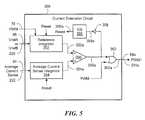
- FIG. 5is a block diagram of an exemplary current extension circuit that can be used as the current extension circuits of FIGS. 1 and 2 ;
- FIG. 6is a graph showing operation of the current extension circuit of FIG. 5 ;
- FIG. 6Ais a graph showing operation of the current extension circuit of FIG. 5 when used in the circuits of FIG. 1 or 2 ;
- FIG. 7is a block diagram showing another exemplary circuit to drive a load, the circuit having a DC-DC voltage converter, in the form of a switching regulator, and current regulators coupled on opposite sides of series coupled light emitting diode (LED) strings, and for which a power to the load (the LEDs) can be pulsed, the circuit also having a generalized condition detection circuit and a generalized current extension circuit, the current extension circuit, response to the condition detection circuit, to extend on times of an extended PWM signal applied to turn on and off the current regulators;
- a DC-DC voltage converterin the form of a switching regulator, and current regulators coupled on opposite sides of series coupled light emitting diode (LED) strings, and for which a power to the load (the LEDs) can be pulsed
- the circuitalso having a generalized condition detection circuit and a generalized current extension circuit, the current extension circuit, response to the condition detection circuit, to extend on times of an extended PWM signal applied to turn on and off the current regulators;
- FIG. 8is a block diagram of an exemplary current extension circuit that can be used to this is the current extension circuit of FIG. 7 ;
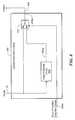
- FIG. 9is a block diagram of an exemplary condition detection circuit that can be used as the condition detection circuit of FIG. 7 ;
- FIG. 10is a block diagram of another exemplary condition detection circuit that can be used as the condition detection circuit of FIG. 7 ;
- FIG. 11is a block diagram of another exemplary condition detection circuit that can be used as the condition detection circuit of FIG. 7 ;
- FIG. 12is a block diagram of another exemplary condition detection circuit that can be used as the condition detection circuit of FIG. 7 .
- boost switching regulatoris used to describe a known type of switching regulator that provides an output voltage higher than an input voltage to the boost switching regulator. While a certain particular circuit topology of boost switching regulator is shown herein, it should be understood that boost switching regulators have a variety of circuit configurations.
- buck switching regulatoris used to describe a known type of switching regulator that provides an output voltage lower than an input voltage to the buck switching regulator. It should be understood that there are still other forms of switching regulators other than a boost switching regulator and other than a buck switching regulator, and this invention is not limited to any one type.
- DC-DC voltage converters(or simply DC-DC converters) are described herein.
- the described DC-DC converterscan be any form of DC-DC converter, including, but not limited to, the above-described boost and buck switching regulators.
- the term “current regulator”is used to describe a circuit or a circuit component that can regulate a current passing through the circuit or circuit component to a predetermined, i.e., regulated, current.
- a current regulatorcan be a “current sink,” which can input a regulated current, or a “current source,” which can output a regulated current.
- a current regulatorhas a “current node” at which a current is output in the case of a current source, or at which a current is input in the case of a current sink.
- an exemplary electronic circuit 10includes a controllable DC-DC converter 12 coupled to one or more loads, for example, series connected diode strings 52 , 54 , 56 , which, in some arrangements, are series connected light emitting diode (LED) strings as may form an LED display or a backlight for a display, for example, a liquid crystal display (LCD).
- the controllable DC-DC converter 12is a switching regulator.
- the series connected LED strings 52 , 54 , 56are coupled to respective current regulators 66 a , 66 b , 66 c , here shown to be current sinks.
- the current regulators 66 a , 66 b , 66 chave respective voltage sense nodes 66 aa , 66 ba , 66 ca , respective current sense nodes 66 ab , 66 bb , 66 cb , and respective current control circuits 64 a , 64 b , 64 c.
- the current regulators 66 a , 66 b , 66 cmaintain a predetermined voltage at the current sense nodes 66 ab , 66 bb , 66 cb , resulting in predetermined currents flowing through resistors 70 a , 70 b , 70 c and through the current regulators 66 a , 66 b , 66 c.
- the switching regulator 12is controlled in a feedback arrangements to maintain sufficient voltage (as little as possible) at the voltage sense nodes 66 aa , 66 ba , 66 ca to allow the current regulators 66 a , 66 b , 66 c to operate.
- the voltages appearing at the voltage sense nodes 66 aa , 66 ba , 66 cacan be different. It will also be recognized that at least a predetermined minimum voltage must be present at each of the voltage sense nodes 66 aa , 66 ba , 66 ca in order for each of the current regulators 66 a , 66 b , 66 c to function properly, i.e., to sink the desired (predetermined) current for which they are designed. In normal operation, it is desirable to maintain voltages at the voltages sense nodes 66 aa , 66 ba , 66 ca as low as possible to conserve power, but high enough to achieve proper operation.
- a multi-input error amplifier 36is coupled to receive voltage signals 58 , 60 , 62 corresponding to voltages appearing at the voltage sense nodes 66 aa , 66 ba , 66 ca , respectively, at one or more inverting input nodes.
- the multi-input error amplifier 36is also coupled to receive a reference voltage signal 38 , for example, 0.5 volts, at a non-inverting input node.
- the multi-input error amplifier 36is configured to generate an error signal 36 a , which is related to an opposite of an arithmetic mean of the voltage signals 58 , 60 , 62 .
- the multi-input error amplifier 36has inputs comprised of metal oxide semiconductor (MOS) transistors.
- the error amplifier 36is a transconductance amplifier, which provides a current-type output.
- a switch 39is coupled to receive the error signal 36 a and configured to generate a switched error signal 39 a under control of an extended pulse width modulated (PWM) signal 86 a , described more fully below.
- PWMpulse width modulated
- the circuit 10can include a capacitor 42 coupled to receive the switched error signal 39 a .
- the capacitor 42has a value of about one hundred picofarads.
- the capacitor 42can provide a loop filter and can have a value selected to stabilize a feedback control loop.
- a DC-DC converter controller 28is coupled to receive the switched error signal 39 a at an error node 28 c.
- An average current to the loadwhich is related to an average power to the load, can be detected by way of resistors 82 a , 82 b , 82 c arranged in a condition detection circuit 82 to provide an average current sense signal 84 having a value (e.g., an analog value) related to an average current delivered to all of the loads (e.g., series coupled LED strings 52 , 54 , 56 ).
- a valuee.g., an analog value
- resistors 82 a , 82 b , 82 care shown to be coupled to each one of the current regulators 66 a , 66 b , 66 c , in other embodiments, resistors may be coupled to only one or only some of the current regulators 66 a , 66 b , 66 c.
- the resistors 82 a , 82 b , 82 care selected to have relatively large values, for example, 10 kOhms, so as not to affect operation of the current regulators 66 a , 66 b , 66 c.
- Average current indicated by the average current sense signal 84is related to a duty cycle of the extended PWM signal 86 a described more fully below. Short duty cycles result in low power to the load (e.g., dim LED strings) and high duty cycles result in high power to the load (e.g., bright LED strings).
- a so-called “current extension circuit” 86is coupled to receive the average current sense signal 84 , coupled to receive a PWM signal 78 (or alternatively, a PWM signal 54 a ), coupled to receive a reference signal 88 , for example, a reference signal, VrefA, (also described below in conjunction with FIG. 3 ), and configured to generate the extended PWM signal 86 a .
- the current extension circuit 86is described more fully below in conjunction with FIG. 5 . Let it suffice here to say that, particularly for very short duty cycles (e.g., short periods of the high state) of the PWM signal 78 , the extended PWM signal 86 a has a longer high state period than the PWM signal 78 .
- the current extension circuit 86can provide the extended PWM signal 86 a , PWM 1 , to extend the on times of the current regulators 66 a , 66 b , 66 c beyond that which they would achieve if controlled by the PWM signal 78 . Operation of the current extension circuit 86 is described more fully in conjunction with FIGS. 5 , 6 , and 6 A.
- a gatefor example, an OR gate 42 , can be coupled to receive the extended PWM signal 86 a , coupled to receive the PWM signal 78 , and configured to generate a control signal 42 a.
- Another gatefor example, an AND gate 44 , can be coupled to receive the control signal 42 a , coupled to receive a circuit error signal, for example, an overvoltage (OVP) signal 45 a , and configured to generate a control signal 44 a.
- a circuit error signalfor example, an overvoltage (OVP) signal 45 a
- the DC-DC converter controller 28can be turned on and off by the control signal 44 a.
- the DC-DC converter controller 28can include a PWM controller 30 configured to generate a DC-DC converter PWM signal 30 a , which is a different PWM signal than the PWM signal 78 described above.
- the DC-DC converter PWM signal 30 acan have a higher frequency (e.g., 100 KHz) than the PWM signal 78 (e.g., 200 Hz).
- a switchfor example, a FET switch 32
- a FET switch 32can be coupled to receive the DC-DC converter PWM signal 30 a at its gate, the FET configured to provide a switching control signal 32 a to the DC-DC converter 12 .
- Operation of the DC-DC converter 12here shown to be a boost switching regulator, in conjunction with the switching control signal 32 a , will be understood.
- Each time the switch 32 closescurrent flows through an inductor 18 , storing energy, and each time the switch 32 opens, the energy is released to a capacitor 22 . If the closure time of the switch 32 is too short, energy cannot build in the inductor 18 to a steady state condition and the switching regulator 12 does not function properly.
- the controllable DC-DC converter 12is also coupled to receive a power supply voltage, Vps, at an input node 12 a and to generate a regulated output voltage 24 at an output node 14 a in response to the error signal 36 a , and in response to the switching control signal 32 a .
- the controllable DC-DC converter 12is a boost switching regulator and the controllable DC-DC converter 12 is coupled to receive the power supply voltage, Vps, at the input node 12 a and to generate a relatively higher regulated output voltage 24 at the output node 12 b.
- the controllable DC-DC converter 12is controlled by an arithmetic mean of the voltage signals 58 , 60 , 62 .
- an arithmetic mean of the voltage signals 58 , 60 , 62that would be too low to provide proper operation of an associated one of the current regulators 66 a , 66 b , 66 c will result in an increase in the error signal 36 a , tending to raise the output voltage 24 of the controllable DC-DC converter 12 .
- the DC-DC converter 12is controlled in a feedback loop arrangement.
- the regulated output voltage 24has a particular desired value.
- the particular desired value of the regulated output voltage 24is that which achieves a high enough voltage at all of the current regulators 66 a , 66 b , 66 c so that they can all operate properly to regulate current as desired.
- the particular desired value of the regulated output voltage 24is that which is as low as possible so that the one or more of the current regulators that receive the lowest voltage(s) (i.e., the greatest voltage drop across the associated series connected LED strings 52 , 54 , 56 ) have just enough voltage to properly operate.
- a low poweris expended in the current regulators 66 a , 66 b , 66 c resulting in high power efficiency while properly illuminating the LEDs.
- the desired value of regulated voltage 24can include a voltage margin (e.g., one volt).
- the particular desired value of the regulated output voltage 24is that which is as low as possible so that the one or more of the current regulators that receive the lowest voltage(s) have just enough voltage to properly operate, plus the voltage margin. Still, an acceptably low power consumption can result.
- the above described error signal 36 awhich is the arithmetic mean of the voltage signals 58 , 60 , 62 , approximately achieves the particular desired value of the regulated output voltage 24 .
- circuit 10can be within a single integrated circuit.
- circuit 80is within an integrated circuit and other components are outside of the integrated circuit.
- the multi-input error amplifier 32is replaced by a multi-input comparator, which either has hysteresis, or which is periodically clocked at which time it makes a comparison.
- the above-described PWM signal 78can be received at a PWM node 80 b of the integrated circuit 80 .
- another signalfor example, a DC signal 79
- an optional PWM generator 54can be coupled to receive the DC signal and can be configured to generate a PWM signal 54 a .
- the PWM signal 54 acan have a duty cycle related to a value of the DC signal 79 .
- Either the PWM signal 78 or the PWM signal 54 acan be used as the PWM signal indicated in other parts of the circuit 10 .
- a duty cycle of the PWM signal 78(or 54 a ) can be varied, which varies a duty cycle of the extended PWM signal 86 a .
- the circuit 10operates in a closed loop arrangement, i.e., the switch 39 is closed the current control circuits 64 a , 64 b , 64 c are enabled, and the PWM controller 28 is enabled, causing the switching control signal 32 a to switch.
- the extended PWM signal 86 ais high, the voltage signals 58 , 60 , 62 are controlled and the currents passing through the current regulators 66 a , 66 b , 66 c are controlled.
- the circuit 10is shut down in several regards. Currents passing through the current regulators 66 a , 66 b , 66 c are stopped by way of the extended PWM signal 86 a received by the current regulators 66 a , 66 b , 66 c .
- the switch 39is opened, causing the capacitor 42 to hold its voltage.
- the PWM controller 28is disabled, causing the switching control signal 32 a to stop switching, and the DC-DC converter 12 to stop converting. When stopped, voltage from the DC-DC converter 12 , i.e., the voltage 24 , is held on the capacitor 22 , but tends to droop with time.
- the PWM 78 signalgoes from low to high for only a short period (i.e., the PWM signal 78 has only a short duty cycle)
- the switching regulatorwere controlled by the PWM signal 78
- the switching regulator 12may not have sufficient time to achieve steady state operation. Therefore, when the PWM signal 78 has a short duty cycle, the current extension circuit 86 can not only extend on times of the current regulators, 66 a , 66 b , 66 c , but can also operate to enable the PWM controller 30 for a time longer than a time that would be achieved by the high state of the PWM signal 78 . Generation of the extended PWM signal 86 a is described below in conjunction with FIG. 5 .
- the PWM controlleris controlled by the PWM signal 78 and not by the extended PWM signal.
- a circuit 200is similar to the circuit 10 of FIG. 1 .
- Current regulators 206 a , 206 b , 206 care similar to the current regulators 66 a , 66 b , 66 c of FIG. 1 , however, the current regulators 206 a , 206 b , 206 c are coupled to the bottom (cathode) ends of the series connected LED strings 52 , 54 , 56 , respectively, instead of to the top (anode) ends of the series connected LED strings 52 , 54 , 56 , respectively.
- an input node 202 eis coupled to receive the regulated output voltage 24 , and output nodes, of which a node 202 d is but one example, are coupled to the anode ends of the series connected LED strings 52 , 54 , 56 , respectively.
- the inverting inputs of the error amplifier 36are coupled to voltage sense node 206 aa , 206 ba , 206 ca.
- the current regulators 206 a , 206 b , 206 chave the voltage sense nodes 206 aa , 206 ba , 206 ca , respectively, current sense nodes 206 ab , 206 bb , 206 cb , respectively, and current control circuits 204 a , 204 b , 204 c , respectively.
- a current extension circuit 224is the same as or similar to the current extension circuit 86 of FIG. 1 .
- Operation of the circuit 200is similar to operation of the circuit 10 described above in conjunction with FIG. 1 .
- an exemplary current regulator circuit 250can be the same as or similar to the current regulator circuits 66 a , 66 b , 66 c of FIG. 1 .
- the current regulator circuit 250can include a node 250 c coupled to receive a PWM signal 272 , which can be the same as or similar to one of the PWM signals 78 , 54 a of FIG. 1 .
- a voltage sense node 250 acan be the same as or similar to the voltage sense nodes 66 aa , 66 ba , 66 ca of FIG. 1 .
- a current sense node 260can be the same as or similar to the current sense nodes 66 ab , 66 bb , 66 cb of FIG. 1 .
- a FET 258can be the same as or similar to the FETs 68 a , 68 b , 68 c of FIG. 1 .
- a resistor 264can be the same as or similar to the resistors 70 a , 70 b , 70 c of FIG. 1 .
- the current regulator circuit 250can include an amplifier 256 having an inverting input coupled to the current sense node 260 , an output coupled to a gate of the FET 258 , and a non-inverting input coupled, at some times, to receive a reference voltage, VrefA, through a switch 254 , and coupled, at other times, to receive another reference voltage, for example, ground, through a switch 270 .
- the switch 254is coupled to receive the PWM signal 272 at its control input, and the switch 270 is coupled to receive an inverted PWM signal 268 a at its control input via an inverter 268 .
- the switches 254 , 256operate in opposition.
- the switch 254In operation, in response to a high state of the PWM signal 272 , the switch 254 is closed and the switch 270 is open. In this state, the current regulator circuit 250 is enabled in a feedback arrangement and acts to maintain the reference voltage 252 as a signal 266 on the resistor 264 , thus controlling a current through the resistor 264 and through the FET 258 .
- the switch 254In response to a low state of the PWM signal 272 , the switch 254 is open and the switch 270 is closed. In this state, an output signal 256 a of the amplifier 256 is forced low, turning off the FET 258 (an N channel FET), and stopping current from flowing through the FET 258 and through the resistor 264 .
- the current regulator circuit 250can be enabled and disabled in accordance with states of the PWM signal 272 .
- an exemplary current regulator circuit 300can be the same as or similar to the current regulator circuits 206 a , 206 b , 206 c of FIG. 2 .
- the current regulator circuit 300can include a node 300 d coupled to receive a PWM signal 310 , which can be the same as or similar to one of the PWM signals 78 , 54 a of FIG. 2 .
- a voltage sense node 300 ccan be the same as or similar to the voltage sense nodes 206 aa , 206 ba , 206 ca of FIG. 2 .
- a current sense node 314can be the same as or similar to the current sense nodes 206 ab , 206 bb , 206 cb of FIG. 2 .
- a FET 324can be the same as or similar to the FETs 210 a , 210 b , 210 c of FIG. 2 .
- a resistor 304can be the same as or similar to the resistors 208 a , 208 b , 208 c of FIG. 2 .
- the current regulator circuit 300can include an amplifier 322 having an inverting input coupled to the current sense node 314 , an output coupled to a gate of the FET 324 , and a non-inverting input coupled, at some times, to receive a reference voltage, VrefB, through a switch 318 , and coupled, at other times, to receive another reference voltage, for example, Vcc, through a switch 308 .
- the switch 318is coupled to receive the PWM signal 310 at its control input
- the switch 308is coupled to receive an inverted PWM signal 306 a at its control input via an inverter 306 .
- the switches 318 , 308operate in opposition.
- the current regulator circuit 300is enabled in a feedback arrangement and acts to maintain the reference voltage 316 as a signal 312 on the resistor 304 , thus controlling a current through the resistor 304 and through the FET 324 .
- the switch 318In response to a low state of the PWM signal 310 , the switch 318 is open and the switch 308 is closed. In this state, an output signal 322 a of the amplifier 322 is forced high, turning off the FET 324 (a P channel FET), and stopping current from flowing through the FET 324 and through the resistor 304 .
- the current regulator circuit 300can be enabled and disabled in accordance with states of the PWM signal 310 .
- a current extension circuit 350can be the same as or similar to the current extension circuits 86 , 224 of FIG. 1 or 2 .
- the current extension circuit 350can be coupled to receive a signal having a value related to a value of an average current sense signal, which can be the same as or similar to the average current sense signals 84 , 222 of FIG. 1 or 2 .
- the current extension circuit 350can also be coupled to receive a reference voltage signal, VrefA or VrefB, which can be the same as or similar to the voltage reference signals 88 , 226 of FIG. 1 or 2 .
- the current extension circuit 350can also be coupled to receive a PWM signal, which can be the same as or similar to the PWM signal 78 of FIGS.
- the current extension circuit 350is configured to generate an extended PWM signal 356 a , PWM 1 , which can be the same as or similar to the extended PWM signals 86 a , 224 a of FIG. 1 or 2 .
- the current extension circuit 350can include a reference integrator 352 coupled to receive the reference voltage signal, VrefA or VrefB, which can be the same as or similar to the voltage reference signals 88 , 226 of FIG. 1 or 2 , and configured to generate a first integrated signal 352 a .
- the current extension circuit 350can also include an average current sense integrator 354 coupled to receive a signal having a value related to a value of the adjustable average current through the load, which can be the same as or similar to the average current sense signals 84 , 222 of FIG. 1 or 2 , and configured to generate a second integrated signal 354 a .
- the current extension circuit 350can also include a comparator 356 coupled to receive the first and second integrated signals 352 a , 354 a , respectively, and configured to generate a comparison signal 356 a .
- An OR gate 362can be coupled to receive the comparison signal 356 a at one input and coupled to receive the PWM signal at a second input.
- the OR gateis configured to generate an extended PWM signal 362 a .
- the extended PWM signal 362 acan be the same as or similar to the extended PWM signals 86 a , 224 a of FIG. 1 or 2 .
- the current extension circuit 350can also include a reset circuit coupled to receive the comparison signal 356 a as an input to an inverter 358 .
- An output signal 358 a from the inverter 358is received by a one-shot circuit 360 configured to generate a pulse output signal 360 a as a reset signal.
- the reset signal 360 ais received by both the reference integrator 352 and by the average current sense integrator 354 .
- a graph 370has a horizontal axis with a scale in units of time in arbitrary units.
- the graphalso has a vertical axis with a scale in units of volts in arbitrary units.
- a series of signalsis shown in the graph of FIG. 6 . Each signal is shown having its own separable range of values on the vertical axis.
- a reference integrator signal 372is indicative of the first integrated signal 352 a generated by the reference integrator 352 of FIG. 5 .
- a current sense integrator signal 374is indicative of the second integrated signal 354 a generated by the average current sense integrator 354 of FIG. 5 .
- a reset signal 376is indicative of the reset signal 360 a of FIG. 5 .
- a PWM signal 378PWM, is indicative of the PWM signal 78 received by the reference integrator 352 of FIG. 5 .
- a comparison signal 380is indicative of the comparison signal 356 a of FIG. 5 .
- An extended PWM signal 382PWM 1 , is indicative of the extended PWM signal 362 a of FIG. 5 .
- the reference integrator signal 372is indicative of an integration that occurs between times t 0 and t 1 , corresponding to start and stop times of a high state of the PWM signal 380 .
- the current sense integrator signal 374is indicative of an integration that begins at the time t 0 , but which ends a later time, t 2 .
- the later time, t 2occurs when the average current sense integrator signal 374 achieves a value, Vb, greater than or equal to a value, Va, achieved by the reference integrator signal 372 , as identified by the comparator 356 of FIG. 5 , and is represented by the comparison signal 380 .
- the high state of the comparison signal 380can be shorter than the high state of the PWM signal 378 .
- the high state of the extended PWM signal 382cannot be shorter than the high state of the PWM signal 378 due to operation of the OR gate 362 of FIG. 5 .
- a graph 400has a horizontal axis with a scale in units of time in arbitrary units.
- the graphalso has a vertical axis with a scale in units of volts and current in volts and in milliamps.
- a series of signalsis shown in the graph of FIG. 6A . Each signal is shown having its own separable range of values on the vertical axis.
- a signal 402is representative of a power supply signal, for example the power supply signal 14 of FIGS. 1 and 2 .
- the power supply signal 402is shown to have a region 402 a indicative of a drop in the power supply voltage, which is undesirable. While but one drop is shown, there can be many drops from time to time.
- a signal 404is representative of a regulated voltage provided by a DC-DC converter, for example the regulated voltage 24 provided by the switching regulator 12 of FIGS. 1 and 2 .
- the regulated voltage signal 404is shown to have a region 404 a with the dip in voltage.
- the dip in voltageis a result of the drop in power supply voltage of the signal 402 .
- the switching regulatorcannot respond immediately to a drop in the power supply voltage, which results in a dip in the output regulated voltage of the switching regulator. As described above, this is very undesirable for reasons that will become apparent below.
- a signal 406is representative of the PWM signal 78 of FIGS. 1 and 2 .
- the PWM signalhas a variable duty cycle in order to control a brightness of the LEDS 52 , 54 , 56 of FIGS. 1 and 2 by way of turning on an off the current regulators 66 a , 66 b , 66 c . Only one duty cycle is shown.
- a signal 408is representative of a current passing through one of the current regulators 66 a , 66 b , 66 c of FIG. 1 or the current regulators 206 a , 206 b , 206 c of FIG. 2 , if the current regulators were controlled by the PWM signal 406 instead of by the extended PWM signal 86 a , 224 a of FIGS. 1 and 2 , respectively.
- the signal 408has a disturbed region 408 a resulting from the drop in the regulated voltage signal 404 . It will be understood that, during the disturbed region 408 a , the LEDS 52 , 54 , 56 will dim by a perceptible amount, which is unacceptable.
- a signal 410is representative of a current passing through one of the current regulators 66 a , 66 b , 66 c of FIG. 1 or the current regulators 206 a , 206 b , 206 c of FIG. 2 when the current regulators 6 are controlled instead by the extended PWM signal 86 a , 224 a of FIGS. 1 and 2 , respectively.
- the signal 410like the signal 408 , also has a disturbed region 410 a . However, during the disturbed region 410 a , on times of the current regulators are extended in time resulting in wider pulses of current passing through the current regulators.
- Preceding circuits and techniquesuse a detection of the average current passing through one or more of the current regulators as a stimulus to extend in time the currents passing through the current regulators.
- the average currentis sensed by the condition detection circuits 82 , 220 of FIGS. 1 and 2 , respectively. Below, it will be shown that other conditions of the circuits can be detected, other than the average current, and other condition signals can be generated, which can be used as stimuli to extend on times of the currents passing through the current regulators.
- condition signalis a binary digital condition, unlike the condition signals 84 , 222 described above, which are variable analog condition signals, resulting in a variable time extension of the extended PWM signals 86 a , 224 a.
- a circuit 420includes a circuit 422 , in which a condition detection circuit 426 and a current extension circuit 428 are more generally shown.
- the condition detection circuit 426is coupled to receive one of a variety of input signals 424 described in conjunction with FIGS. 9-12 below.
- the condition detection circuit 426is configured to generate a condition signal 426 a .
- a current extension circuit 428is coupled to receive the condition signal, coupled to receive the PWM signal 78 , and configured to generate an extended PWM signal 430 .
- a current extension circuit 450can be the same as or similar to the current extension circuit 428 of FIG. 7 .
- the current extension circuit 450can be coupled to receive the PWM signal 78 and coupled to receive the condition signal 426 a.
- the current extension circuit 450can include a pulse extender circuit 452 coupled to receive the PWM signal 78 .
- the pulse extender circuitis configured to generate an extended signal 452 a , which is like the PWM signal 78 but having a state, for example, a first or high state, extended in time from that of the PWM signal 78 .
- the current extension circuit 450can also include a single pole double throw switch 454 coupled to receive the PWM signal 78 and also coupled to receive the extended signal 452 a .
- the switch 454is configured to generate a signal 454 a , which is the same as or similar to the extended PWM signal 430 of FIG. 7 .
- the switch 454is controlled by the condition signal 426 a , which can be a two state binary signal.
- Pulse extender circuitsare known and can be made with a variety of configurations.
- a pulse extender circuitcan be made with a current source feeding into a capacitor to extend one of the edges, for example, the falling edge, of an input pulse.
- a pulse extendercan be formed as a Layman's pulse extender.
- a pulse extendercan be formed using a ripple counter.
- the pulse extender circuit 452can generated the extended signal 452 a having a state, for example, a high state, that is longer in time than a corresponding state of the PWM signal 78 by a predetermined amount of time.
- the predetermined amount of timeis about two microseconds. However, the predetermined time can be longer or shorter than two microseconds.
- condition signal 426 ain accordance with two binary states, provides either the PWM signal 78 or the extended signal 452 a as the extended PWM signal 430 by way of the switch 454 .
- FIGS. 9-12show a variety of circuits that can be used to form condition detection circuits and associated condition signals that can be used as the condition detection circuit 426 and condition signal 426 a of FIG. 7 .
- a condition detection circuit 470can be coupled to receive and act upon the power supply voltage 14 of FIG. 7 , differentiating the power supply voltage 14 , and therefore, acting upon a rate of change of the power supply voltage 14 .
- the condition detection circuit 470can be the same as or similar to the condition detection circuit 426 of FIG. 7 .
- the condition detection circuit 470can include a capacitor 474 and a resistor 476 coupled around an operational amplifier 472 to form a differentiator.
- the operational amplifier 472is coupled to receive the power supply signal 14 and configured to generate a differentiated signal 472 a .
- a comparator 474is coupled to receive the differentiated signal 472 a at one input and coupled to receive a voltage threshold signal 476 at another input.
- the comparator 474is configured to generate a comparison signal 474 a .
- the comparison signal 474 ahas two states, a first state, e.g., a high state, indicative of a rate of change of the power supply voltage 14 being above the threshold value 476 and a second different state indicative of the rate of change of the power supply voltage 14 being below the threshold value 476 .
- a flip-flop 478is coupled to receive the comparison signal 474 a at a set input.
- the flip-flop 478is configured to generate an output signal 478 a at a Q output.
- the flip-flop 478is also configured to generate another output signal 478 b at an inverted Q output.
- a time delay module 480is coupled to receive the signal 478 b and configured to generate a delayed signal 480 a received by the flip-flop 478 at a reset input.
- the time delay module 480provides a time delay selected to result in the condition signal 426 a taking on a first state, for example, a high state, for a predetermined amount of time.
- the predetermined amount of timecan be, for example, two microseconds.
- the signal 478 a generated by the flip-flop 478can be the same as or similar to the condition signal 426 a of FIGS. 7 and 8 .
- condition signal 478 a of FIG. 9is extended for the predetermined amount of time when the condition signal 426 a is indicative of the power supply voltage 14 having a high rate of change, and the signal 454 a is not extended, i.e., it is the same as the PWM signal 78 , when the power supply voltage 14 does not have a high rate of change.
- condition detection circuitsare shown in FIGS. 10-12 below, each without a flip-flop or time delay circuit.
- each of these circuitscan have a flip-flop and time delay circuit to generate a selected state of an output signal only for a predetermined amount of time.
- a condition detection circuit 490can be coupled to receive and act upon the power supply voltage 14 of FIG. 7 , threshold detecting the power supply voltage 14 , and therefore, acting upon a value of the power supply voltage 14 .
- the condition detection circuit 490can be the same as or similar to the condition detection circuit 426 of FIG. 7 .
- the condition detection circuit 490can include a comparator 492 coupled to receive the power supply voltage 14 at one input and coupled to receive a voltage threshold signal 494 at another input.
- the comparator 492is configured to generate a comparison signal 492 a .
- the comparison signal 492 ahas two states, a first state, e.g., a high state, indicative of a value of the power supply voltage 14 being below the threshold value 494 and a second different state indicative of the value of the power supply voltage 14 being above the threshold value 494 .
- condition signal 492 a of FIG. 10is extended when the condition signal 426 a is indicative of the power supply voltage 14 being below a predetermined value, and the signal 454 a is not extended, i.e., it is the same as the PWM signal 78 , when the power supply voltage 14 is above the predetermined value.
- a condition detection circuit 510can be coupled to receive and act upon the PWM signal 78 of FIG. 7 , detecting when the PWM signal 78 has a duty cycle below a threshold value.
- the condition detection circuit 510can be the same as or similar to the condition detection circuit 426 of FIG. 7 .
- the condition detection circuit 510can include a low pass filter 512 coupled to receive the PWM signal 78 and configured to generate a filtered signal 512 a .
- the condition detection circuit 510can include a comparator 514 coupled to receive the filtered signal 512 a at one input and coupled to receive a voltage threshold signal 516 at another input.
- the comparator 514is configured to generate a comparison signal 514 a .
- the comparison signal 514 ahas two states, a first state, e.g., a high state, indicative of a value of the duty cycle of the PWM signal 78 being below the threshold value 516 and a second different state indicative of the value of the duty cycle of the PWM signal being above the threshold value 516 .
- condition signal 514 a of FIG. 11is extended when the condition signal 426 a is indicative of the duty cycle of the PWM signal 78 being below a predetermined value, and the signal 454 a is not extended, i.e., it is the same as the PWM signal 78 , when the duty cycle of the PWM signal 78 is above the predetermined value.
- a condition detection circuit 530can be coupled to receive and act upon the PWM signal 78 of FIG. 7 , detecting when the PWM signal 78 has a duty cycle below a threshold value.
- a so-called “soft start” signal 544is also used.
- the condition detection circuit 530can be the same as or similar to the condition detection circuit 426 of FIG. 7 .
- the soft start signalis a signal generated when the circuit 420 of FIG. 7 is first powered on.
- the soft start signalhas a first state, e.g., a high state, for a predetermined period of time following the time that power is applied to the circuit 420 , and a second different state thereafter.
- the first state time periodis about five milliseconds.
- the soft start signal 540is provided in a closed loop arrangement having a variable time period.
- the LEDs 52 , 54 , 56( FIGS. 1 and 2 ) are monitored by other circuits (not shown) while the currents through the current regulators are set to a highest current condition (or alternatively, a lower current condition), and the soft start signal 504 has the first state until the LEDs 52 , 54 , 56 achieve or approach their proper closed loop regulation voltage at associated voltage sense nodes.
- the condition detection circuit 530can include a low pass filter 532 coupled to receive the PWM signal 78 and configured to generate a filtered signal 532 a .
- the condition detection circuit 530can include a comparator 534 coupled to receive the filtered signal 532 a at one input and coupled to receive a voltage threshold signal 536 at another input.
- the comparator 534is configured to generate a comparison signal 534 a .
- the comparison signal 534 ahas two states, a first state, e.g., a high state, indicative of a value of the duty cycle of the PWM signal 78 being below the threshold value 516 and a second different state indicative of the value of the duty cycle of the PWM signal being above the threshold value 516 .
- the soft start signalcan be received by an inverter 546 a , configured to generate an inverted soft start signal 546 a
- a gatefor example, an AND gate, is coupled to receive the comparison signal 534 a at one input and coupled to receive the inverted soft start signal at another input.
- the AND gateis configured to generate a condition signal 538 a.
- condition signal 538 a of FIG. 11is extended when the condition signal 426 a is indicative of the duty cycle of the PWM signal 78 being below a predetermined value and when the soft start signal is low (after a soft start period), and the signal 454 a is not extended, i.e., it is the same as the PWM signal 78 , when the duty cycle of the PWM signal 78 is above the predetermined value or when the soft start signal is high (during the soft start period).
- the condition detection circuit of FIGS. 9-12result in the extended PWM signal being generated to have the extended state (compared to the PWM signal 78 ) for a predetermined time.
- the extended PWM signalis always generated to have the extended state.
- the condition signalis essentially continuous (i.e., static), since the condition that causes the extended state is continuous.
Landscapes
- Dc-Dc Converters (AREA)
Abstract
Description
Claims (43)
Priority Applications (4)
| Application Number | Priority Date | Filing Date | Title |
|---|---|---|---|
| US13/177,075US9265104B2 (en) | 2011-07-06 | 2011-07-06 | Electronic circuits and techniques for maintaining a consistent power delivered to a load |
| PCT/US2012/044149WO2013006304A1 (en) | 2011-07-06 | 2012-06-26 | Electronic circuits and techniques for maintaining a consistent power delivered to a load |
| TW104113675ATWI587633B (en) | 2011-07-06 | 2012-07-03 | Electronic circuits and method of generating adjustable average current through load with the same |
| TW101123896ATWI514776B (en) | 2011-07-06 | 2012-07-03 | Electronic circuits and techniques for maintaining a consistent power delivered to a load |
Applications Claiming Priority (1)
| Application Number | Priority Date | Filing Date | Title |
|---|---|---|---|
| US13/177,075US9265104B2 (en) | 2011-07-06 | 2011-07-06 | Electronic circuits and techniques for maintaining a consistent power delivered to a load |
Publications (2)
| Publication Number | Publication Date |
|---|---|
| US20130009556A1 US20130009556A1 (en) | 2013-01-10 |
| US9265104B2true US9265104B2 (en) | 2016-02-16 |
Family
ID=46548809
Family Applications (1)
| Application Number | Title | Priority Date | Filing Date |
|---|---|---|---|
| US13/177,075Active2033-08-30US9265104B2 (en) | 2011-07-06 | 2011-07-06 | Electronic circuits and techniques for maintaining a consistent power delivered to a load |
Country Status (3)
| Country | Link |
|---|---|
| US (1) | US9265104B2 (en) |
| TW (2) | TWI587633B (en) |
| WO (1) | WO2013006304A1 (en) |
Cited By (5)
| Publication number | Priority date | Publication date | Assignee | Title |
|---|---|---|---|---|
| US20130147360A1 (en)* | 2011-12-07 | 2013-06-13 | Tae-kyoung Kang | Led driver apparatus |
| US20130271701A1 (en)* | 2012-04-12 | 2013-10-17 | Xiang Yang | LED Backlight Drive Circuit, Liquid Crystal Display Device and Driving Method |
| US9642203B2 (en) | 2015-06-12 | 2017-05-02 | Allegro Microsystems, Llc | Controlling dimming ratio and output ripple voltage |
| CN113228828A (en)* | 2018-11-26 | 2021-08-06 | 上海晶丰明源半导体股份有限公司 | Control circuit, driving system, chip, control method and driving method |
| US11272591B1 (en) | 2020-12-02 | 2022-03-08 | Allegro Microsystems, Llc | Constant power light emitting diode (LED) driver |
Families Citing this family (32)
| Publication number | Priority date | Publication date | Assignee | Title |
|---|---|---|---|---|
| US8169161B2 (en) | 2007-11-16 | 2012-05-01 | Allegro Microsystems, Inc. | Electronic circuits for driving series connected light emitting diode strings |
| TWI532028B (en)* | 2010-05-06 | 2016-05-01 | 立錡科技股份有限公司 | Flat panel display, light emitting module for use in flat panel display, and integrated circuit for use in light emitting module |
| US9155156B2 (en) | 2011-07-06 | 2015-10-06 | Allegro Microsystems, Llc | Electronic circuits and techniques for improving a short duty cycle behavior of a DC-DC converter driving a load |
| TWI444091B (en)* | 2011-08-12 | 2014-07-01 | Raydium Semiconductor Corp | Led driver |
| KR101971287B1 (en)* | 2011-08-30 | 2019-04-23 | 매그나칩 반도체 유한회사 | Led driver apparatus |
| CN102497706B (en)* | 2011-12-15 | 2014-06-25 | 成都芯源系统有限公司 | LED driving device and driving method and controller |
| TWI471845B (en)* | 2012-08-01 | 2015-02-01 | 安恩科技股份有限公司 | Current distributor |
| US8957607B2 (en) | 2012-08-22 | 2015-02-17 | Allergo Microsystems, LLC | DC-DC converter using hysteretic control and associated methods |
| CN108601169B (en) | 2013-08-09 | 2020-01-10 | 意法半导体研发(深圳)有限公司 | Driving apparatus for light emitting device and method thereof |
| TWI497883B (en)* | 2013-08-14 | 2015-08-21 | Beyond Innovation Tech Co Ltd | Boost apparatus with over-current and over-voltage protection function |
| US9615413B2 (en) | 2013-08-29 | 2017-04-04 | Allegro Microsystems, Llc | Driver circuit using dynamic regulation and related techniques |
| EP3061023B1 (en) | 2013-10-25 | 2020-01-01 | OneVisage SA | A method and a system for performing 3d-based identity verification of individuals with mobile devices |
| US9456481B2 (en)* | 2014-02-25 | 2016-09-27 | Earl W. McCune, Jr. | High-efficiency, wide dynamic range dimming for solid-state lighting |
| KR20150117520A (en)* | 2014-04-10 | 2015-10-20 | 삼성전자주식회사 | Light emitting diode driving circuit, light emitting diode controlling circuit, and method for controlling light emitting diode |
| CN106605182B (en)* | 2014-05-12 | 2018-03-02 | 驱动封闭合资股份公司 | For the device for the DC current for producing the power circuit for flowing into load |
| US9774257B2 (en) | 2014-05-23 | 2017-09-26 | Allegro Microsystems, Llc | Control circuit for a switching regulator driving an LED load with controlled PWM dimming |
| MX367317B (en)* | 2014-08-01 | 2019-08-15 | Lutron Electronics Co | Load control device for controlling a driver for a lighting load. |
| EP3213602B1 (en)* | 2014-10-28 | 2020-05-27 | Texas Instruments Incorporated | Dual control led driver |
| FR3030944A1 (en)* | 2014-12-17 | 2016-06-24 | St Microelectronics Tours Sas | SYSTEM FOR BALANCING CURRENT SEMICONDUCTOR ELEMENTS IN PARALLEL |
| US10136487B2 (en) | 2015-02-27 | 2018-11-20 | Diodes Incorporated | Power optimization for linear regulator |
| US10278242B2 (en)* | 2015-04-09 | 2019-04-30 | Diddes Incorporated | Thermal and power optimization for linear regulator |
| TWI617219B (en)* | 2015-05-29 | 2018-03-01 | 線性科技股份有限公司 | Maintaining output capacitance voltage in led driver systems during pulse width modulation off times |
| US9642200B2 (en)* | 2015-05-29 | 2017-05-02 | Linear Technology Corporation | Maintaining LED driver operating point during PWM off times |
| US20160374165A1 (en)* | 2015-06-18 | 2016-12-22 | Innolux Corporation | Backlight module and liquid-crystal display device using the same |
| CN106940985A (en)* | 2016-01-04 | 2017-07-11 | 群创光电股份有限公司 | Backlight module and liquid crystal display device |
| US9538601B1 (en) | 2015-10-08 | 2017-01-03 | Allegro Microsystems, Llc | Method and apparatus for driving loads using a DC-DC converter |
| US9825528B2 (en)* | 2015-12-28 | 2017-11-21 | Allegro Microsystems, Llc | Compensating for voltage changes in driver circuits |
| US10045411B2 (en)* | 2016-05-18 | 2018-08-07 | Avago Technologies General Ip (Singapore) Pte. Ltd. | Dual mode light emitting diode (LED) driver |
| TWI656809B (en)* | 2017-09-29 | 2019-04-11 | 大陸商東莞市高效電控有限公司 | Light-emitting diode driving circuit and lighting device thereof |
| US11522448B2 (en)* | 2019-05-29 | 2022-12-06 | Alpha And Omega Semiconductor (Cayman) Limited | Autonomous current sharing for power stages |
| DE102019005029A1 (en)* | 2019-07-18 | 2021-01-21 | Giesecke+Devrient Currency Technology Gmbh | LIGHT SOURCE DRIVER CIRCUIT, OPTICAL MEASURING DEVICE WITH THE LIGHT SOURCE DRIVER CIRCUIT, DEVICE FOR CHECKING VALUE DOCUMENTS, AND METHOD OF OPERATING A LIGHT SOURCE LOAD USING THE LIGHT SOURCE DRIVER CIRCUIT |
| CN116453471A (en)* | 2023-04-12 | 2023-07-18 | 昂宝电子(上海)有限公司 | Channel current control device and method for mini LED backlight source |
Citations (103)
| Publication number | Priority date | Publication date | Assignee | Title |
|---|---|---|---|---|
| US4739226A (en) | 1985-04-18 | 1988-04-19 | Yazaki Corporation | Dimming circuit having switching transistor protection means |
| JPH03196280A (en) | 1989-12-25 | 1991-08-27 | Toko Inc | Multi-input operational amplifier circuit and integrating circuit using the amplifier circuit |
| JPH0644807A (en) | 1992-03-24 | 1994-02-18 | Sasaki Denki Seisakusho:Kk | Signal indication lamp |
| US5905387A (en) | 1995-11-03 | 1999-05-18 | Stmicroelectronics, S.R.L. | Analog voltage-signal selector device |
| JPH11507750A (en) | 1995-06-12 | 1999-07-06 | サムスン エレクトロニクス カンパニー リミテッド | Digitizer controller |
| WO2000013310A1 (en) | 1998-08-31 | 2000-03-09 | The B.F. Goodrich Company | Multiplexing amplifier |
| EP1079667A2 (en) | 1999-08-19 | 2001-02-28 | Schott Fibre Optics (UK) Ltd | Lighting control device |
| US6222385B1 (en) | 1999-01-12 | 2001-04-24 | Hyundai Electronics Industries Co., Ltd. | Level shifter circuit |
| US6271693B1 (en) | 1997-12-12 | 2001-08-07 | United Microelectronics Corp. | Multi-function switched-current magnitude sorter |
| WO2002003087A1 (en) | 2000-07-05 | 2002-01-10 | Infineon Technologies Ag | Amplifier circuit with offset compensation |
| US6400715B1 (en) | 1996-09-18 | 2002-06-04 | Texas Instruments Incorporated | Network address matching circuit and method |
| JP2002257871A (en) | 2001-03-06 | 2002-09-11 | Toshiba Corp | Semiconductor integrated circuit |
| JP2002281345A (en) | 2001-03-16 | 2002-09-27 | Matsushita Electric Ind Co Ltd | Video signal processing circuit and camera system |
| JP2003063062A (en) | 2001-08-23 | 2003-03-05 | Oki Data Corp | Control voltage generating circuit, and printhead and printer using the same |
| US20030110344A1 (en) | 1996-09-18 | 2003-06-12 | Andre Szczepanek | Communications systems, apparatus and methods |
| JP2003215534A (en) | 2002-01-23 | 2003-07-30 | Seiko Epson Corp | LCD backlight control device |
| US6621235B2 (en) | 2001-08-03 | 2003-09-16 | Koninklijke Philips Electronics N.V. | Integrated LED driving device with current sharing for multiple LED strings |
| US6636104B2 (en) | 2000-06-13 | 2003-10-21 | Microsemi Corporation | Multiple output charge pump |
| US6690146B2 (en) | 2002-06-20 | 2004-02-10 | Fairchild Semiconductor Corporation | High efficiency LED driver |
| US20040051478A1 (en) | 2002-06-28 | 2004-03-18 | Tosiba Lighting & Technology Corporation | Electronic ballast and lighting fixture |
| US20040080273A1 (en) | 2002-10-08 | 2004-04-29 | Masayasu Ito | Lighting circuit |
| US6822403B2 (en) | 2002-05-07 | 2004-11-23 | Rohm Co., Ltd. | Light emitting element drive device and electronic device having light emitting element |
| US20040251854A1 (en) | 2003-06-13 | 2004-12-16 | Tomoaki Matsuda | Power supply for lighting |
| US20040251942A1 (en) | 2003-06-12 | 2004-12-16 | Delta Electronics, Inc. | PWM buffer circuit for adjusting a frequency and a duty cycle of a PWM signal |
| US20050007085A1 (en) | 2003-07-07 | 2005-01-13 | Rohm Co., Ltd. | Load driving device and portable apparatus utilizing such driving device |
| US20050088207A1 (en) | 2003-05-09 | 2005-04-28 | Semtech Corporation | Method and apparatus for driving LED's |
| JP2005116738A (en) | 2003-10-07 | 2005-04-28 | 21 Aomori Sangyo Sogo Shien Center | LED driving circuit and power saving method thereof |
| JP2005122979A (en) | 2003-10-15 | 2005-05-12 | Matsumura Denki Seisakusho:Kk | Lighting device |
| US20050104542A1 (en) | 2003-10-03 | 2005-05-19 | Al-Aid Corporation | LED-switching controller and LED-switching control method |
| US20050110469A1 (en) | 2003-11-25 | 2005-05-26 | Sharp Kabushiki Kaisha | Power supply circuit |
| US20050156540A1 (en) | 2003-12-16 | 2005-07-21 | Ball Newton E. | Inverter with two switching stages for driving lamp |
| US6930679B2 (en) | 2002-11-22 | 2005-08-16 | Macroblock, Inc. | System of LED drivers for driving display devices |
| US20050243022A1 (en) | 2004-04-30 | 2005-11-03 | Arques Technology, Inc. | Method and IC driver for series connected R, G, B LEDs |
| US20050243041A1 (en) | 2004-04-29 | 2005-11-03 | Micrel, Incorporated | Light emitting diode driver circuit |
| US6963175B2 (en) | 2001-08-30 | 2005-11-08 | Radiant Research Limited | Illumination control system |
| JP2006005381A (en) | 2005-09-14 | 2006-01-05 | Sony Corp | Portable device |
| US20060022916A1 (en) | 2004-06-14 | 2006-02-02 | Natale Aiello | LED driving device with variable light intensity |
| US20060028147A1 (en) | 2004-08-03 | 2006-02-09 | Minebea Co., Ltd | Discharge lamp lighting apparatus for lighting multiple discharge lamps |
| JP3755770B2 (en) | 2003-07-07 | 2006-03-15 | ローム株式会社 | Load drive device and portable device |
| JP2006129862A (en) | 2004-10-05 | 2006-05-25 | Rikujo Yoshoku Kogaku Kenkyusho:Kk | Seafood rearing device and foreign matter removing method |
| US20060114954A1 (en) | 2004-11-29 | 2006-06-01 | Footshen Wong | Highly efficient driving of photoflash diodes using low and fixed voltage drop-out current sink |
| US20060125320A1 (en) | 2004-11-19 | 2006-06-15 | Takanori Namba | Lighting control circuit for vehicle lighting device |
| US20060139299A1 (en) | 2004-12-24 | 2006-06-29 | Kenshi Tsuchiya | Surface light source control device |
| US20060170287A1 (en) | 2005-01-31 | 2006-08-03 | Koito Manufacturing Co., Ltd. | Lighting control circuit for vehicle lighting fixture |
| JP2006521659A (en) | 2003-03-28 | 2006-09-21 | マイクロン・テクノロジー・インコーポレーテッド | Method for reducing power consumption when detecting resistive memory |
| US20060250824A1 (en) | 2005-05-09 | 2006-11-09 | Wekhande Shashank S | Capacitor charging methods and apparatus |
| US20060259648A1 (en) | 2005-05-13 | 2006-11-16 | Sanjive Agarwala | Concurrent read response acknowledge enhanced direct memory access unit |
| JP2006318326A (en) | 2005-05-16 | 2006-11-24 | Renesas Technology Corp | Power supply circuit |
| US7148632B2 (en) | 2003-01-15 | 2006-12-12 | Luminator Holding, L.P. | LED lighting system |
| WO2006136321A1 (en) | 2005-06-20 | 2006-12-28 | Austriamicrosystems Ag | Power supply system and method for the operation of an electrical load |
| WO2007043389A1 (en) | 2005-10-14 | 2007-04-19 | National Institute Of Advanced Industrial Science And Technology | Cmos amplifier using 4-terminal dual insulating gate field-effect transistor, multi-input cmos amplifier using the same, high-gain multi-input cmos amplifier, high-gain highly-stable multi-input cmos amplifier, and multi-input cmos differential amplifier |
| JP2007120506A (en) | 2001-09-28 | 2007-05-17 | Kubota Corp | Multi-cylinder engine |
| JP2007129862A (en) | 2005-11-07 | 2007-05-24 | Rohm Co Ltd | Power supply |
| US20070120506A1 (en) | 2005-11-30 | 2007-05-31 | Semtech Corporation | High efficiency power supply for LED lighting applications |
| US20070182701A1 (en) | 2006-02-06 | 2007-08-09 | Min-Gyu Kim | Method of driving a lamp, lamp driving apparatus, and liquid crystal display device having the same |
| WO2007096868A1 (en) | 2006-02-23 | 2007-08-30 | Microsemi Corp. - Analog Mixed Signal Group Ltd. | Voltage controlled backlight driver |
| US7291989B2 (en) | 2004-12-07 | 2007-11-06 | Koito Manufacturing Co., Ltd. | Lighting control circuit for vehicle lighting equipment |
| US20070267978A1 (en) | 2006-05-22 | 2007-11-22 | Exclara Inc. | Digitally controlled current regulator for high power solid state lighting |
| US7317403B2 (en) | 2005-08-26 | 2008-01-08 | Philips Lumileds Lighting Company, Llc | LED light source for backlighting with integrated electronics |
| US20080048573A1 (en) | 2006-07-17 | 2008-02-28 | Powerdsine, Ltd. - Microsemi Corporation | Controlled Bleeder for Power Supply |
| US20080110469A1 (en) | 2006-11-13 | 2008-05-15 | Stanley Weinberg | Strapless flexible tribo-charged respiratory facial mask and method |
| US20080144236A1 (en) | 2006-12-18 | 2008-06-19 | Yung-Hsin Chiang | Driving circuit and related driving method for providing feedback control and open-circuit protection |
| US20080164828A1 (en) | 2007-01-04 | 2008-07-10 | Gregory Szczeszynski | Electronic circuit for driving a diode load |
| US20080243041A1 (en) | 2007-03-27 | 2008-10-02 | Patricia Brenner | Butt and thigh massager |
| US7466082B1 (en) | 2005-01-25 | 2008-12-16 | Streamlight, Inc. | Electronic circuit reducing and boosting voltage for controlling LED current |
| JP2008311602A (en) | 2007-05-17 | 2008-12-25 | Seiko Npc Corp | Led drive circuit |
| US7479743B2 (en) | 2005-12-12 | 2009-01-20 | Koito Manufacturing Co., Ltd. | Vehicle lighting apparatus |
| US20090021384A1 (en) | 2007-07-17 | 2009-01-22 | Microsemi Corp.- Analog Mixed Signal Group Ltd. | Method of Sampling a Modulated Signal Driven Channel |
| US7482765B2 (en) | 2005-07-12 | 2009-01-27 | Koito Manufacturing Co., Ltd. | Lighting control apparatus of lighting device for vehicle |
| US7528551B2 (en) | 2007-02-26 | 2009-05-05 | Semiconductor Components Industries, L.L.C. | LED control system |
| US20090128045A1 (en) | 2007-11-16 | 2009-05-21 | Gregory Szczeszynski | Electronic Circuits for Driving Series Connected Light Emitting Diode Strings |
| US20090195183A1 (en) | 2008-02-05 | 2009-08-06 | Ta-Yung Yang | Controller of led lighting to control the maximum voltage of leds and the maximum voltage across current sources |
| US20090289559A1 (en) | 2008-05-20 | 2009-11-26 | Texas Instruments Incorporated | Led device and led driver |
| US20090302776A1 (en) | 2008-06-10 | 2009-12-10 | Gregory Szczeszynski | Electronic circuit for driving a diode load with a predetermined average current |
| WO2009157763A2 (en) | 2008-06-24 | 2009-12-30 | Eldolab Holding B.V. | Control unit for a led assembly and lighting system |
| WO2010000475A1 (en) | 2008-07-02 | 2010-01-07 | Acandis Gmbh & Co. Kg | Filter for a blood vessel, and treatment system with such a filter |
| WO2010004475A1 (en) | 2008-07-09 | 2010-01-14 | Nxp B.V. | A switched mode power converter and method of operating the same |
| US20100019696A1 (en)* | 2008-07-25 | 2010-01-28 | Sanken Electric Co., Ltd. | Power converter |
| US20100052552A1 (en) | 2008-09-01 | 2010-03-04 | Sanken Electric Co., Ltd. | Apparatus for lighting leds |
| US20100060177A1 (en) | 2008-09-08 | 2010-03-11 | Panasonic Corporation | Load driving apparatus |
| US20100066255A1 (en) | 2008-09-12 | 2010-03-18 | General Electric Company | Adjustable color solid state lighting |
| US20100109550A1 (en) | 2008-11-03 | 2010-05-06 | Muzahid Bin Huda | LED Dimming Techniques Using Spread Spectrum Modulation |
| US20100140621A1 (en) | 2008-12-04 | 2010-06-10 | Samsung Electronics Co., Ltd. | Light blocking member having variabe transmittance, display panel including the same, and manufacturing method thereof |
| US20100148691A1 (en) | 2008-12-12 | 2010-06-17 | O2Micro, Inc. | Driving circuit with dimming controller for driving light sources |
| US20100164581A1 (en) | 2008-12-31 | 2010-07-01 | Bcd Semiconductor Manufacturing Limited | Pulsed width modulated control method and apparatus |
| US20100207547A1 (en)* | 2009-01-22 | 2010-08-19 | Yosifumi Kuroki | Switching power supply for an illumination device with precision current control |
| US20100259177A1 (en)* | 2009-04-14 | 2010-10-14 | Alexander Mednik | Led driver with extended dimming range and method for achieving the same |
| US20100327835A1 (en) | 2009-06-26 | 2010-12-30 | Intersil Americas Inc. | Integrator for providing overshoot protection and light switching mode during non-zero load condition for an led driver circuitry |
| US20110026277A1 (en) | 2009-07-28 | 2011-02-03 | Nxp B.V. | driving circuit |
| US20110032008A1 (en) | 2009-08-07 | 2011-02-10 | Freescale Semiconductor, Inc. | Pulse width modulation frequency conversion |
| US20110062929A1 (en) | 2009-09-17 | 2011-03-17 | Linear Technology Corporation | Feedback control of a dc/dc power converter |
| US7928670B2 (en) | 2008-06-30 | 2011-04-19 | Iwatt Inc. | LED driver with multiple feedback loops |
| US20110133645A1 (en) | 2009-12-30 | 2011-06-09 | Ching-Chuan Kuo | Circuits and methods for powering light source with balanced currents |
| US20110204947A1 (en) | 2010-02-24 | 2011-08-25 | Intersil Americas Inc. | Method and apparatus for adaptively modifying a pulse width of a pulse width modulated output |
| US20110234122A1 (en) | 2010-03-23 | 2011-09-29 | Bo Yu | Circuitry for driving light emitting diodes and associated methods |
| US20110298384A1 (en) | 2010-06-03 | 2011-12-08 | Rohm Co., Ltd. | Led driving device and electrical apparatus using the same |
| US20120133299A1 (en) | 2010-11-30 | 2012-05-31 | Infineon Technologies Ag | Multi Channel LED Driver |
| US20120146541A1 (en) | 2010-12-13 | 2012-06-14 | Allegro Microsystems, Inc. | Circuitry to control a switching regulator |
| WO2013006272A1 (en) | 2011-07-06 | 2013-01-10 | Allegro Microsystems, Inc. | Electronic circuits and techniques for improving a short duty cycle behavior of a dc-dc converter driving a load |
| US20130162152A1 (en) | 2011-12-22 | 2013-06-27 | Allegro Microsystems, Inc. | Circuitry to drive parallel loads sequentially |
| US8482225B2 (en) | 2011-04-28 | 2013-07-09 | Allegro Microsystems, Llc | Electronic circuits and methods for driving a diode load |
| US20130207632A1 (en) | 2012-02-13 | 2013-08-15 | Gurjit Singh THANDI | System and method for improved line transient response in current mode boost converters |
| US20140055045A1 (en) | 2012-08-22 | 2014-02-27 | Allegro Microsystems, Inc. | DC-DC Converter Using Hysteretic Control and Associated Methods |
Family Cites Families (1)
| Publication number | Priority date | Publication date | Assignee | Title |
|---|---|---|---|---|
| CN102014543B (en)* | 2010-07-02 | 2011-12-28 | 凹凸电子(武汉)有限公司 | Drive circuit and method of drive light source and controller |
- 2011
- 2011-07-06USUS13/177,075patent/US9265104B2/enactiveActive
- 2012
- 2012-06-26WOPCT/US2012/044149patent/WO2013006304A1/enactiveApplication Filing
- 2012-07-03TWTW104113675Apatent/TWI587633B/enactive
- 2012-07-03TWTW101123896Apatent/TWI514776B/enactive
Patent Citations (131)
| Publication number | Priority date | Publication date | Assignee | Title |
|---|---|---|---|---|
| US4739226A (en) | 1985-04-18 | 1988-04-19 | Yazaki Corporation | Dimming circuit having switching transistor protection means |
| JPH03196280A (en) | 1989-12-25 | 1991-08-27 | Toko Inc | Multi-input operational amplifier circuit and integrating circuit using the amplifier circuit |
| JPH0644807A (en) | 1992-03-24 | 1994-02-18 | Sasaki Denki Seisakusho:Kk | Signal indication lamp |
| JPH11507750A (en) | 1995-06-12 | 1999-07-06 | サムスン エレクトロニクス カンパニー リミテッド | Digitizer controller |
| US5905387A (en) | 1995-11-03 | 1999-05-18 | Stmicroelectronics, S.R.L. | Analog voltage-signal selector device |
| US6400715B1 (en) | 1996-09-18 | 2002-06-04 | Texas Instruments Incorporated | Network address matching circuit and method |
| US20030110344A1 (en) | 1996-09-18 | 2003-06-12 | Andre Szczepanek | Communications systems, apparatus and methods |
| US6271693B1 (en) | 1997-12-12 | 2001-08-07 | United Microelectronics Corp. | Multi-function switched-current magnitude sorter |
| WO2000013310A1 (en) | 1998-08-31 | 2000-03-09 | The B.F. Goodrich Company | Multiplexing amplifier |
| US6222385B1 (en) | 1999-01-12 | 2001-04-24 | Hyundai Electronics Industries Co., Ltd. | Level shifter circuit |
| EP1079667A2 (en) | 1999-08-19 | 2001-02-28 | Schott Fibre Optics (UK) Ltd | Lighting control device |
| EP1079667A3 (en) | 1999-08-19 | 2003-11-12 | Schott Fibre Optics (UK) Ltd | Lighting control device |
| US6636104B2 (en) | 2000-06-13 | 2003-10-21 | Microsemi Corporation | Multiple output charge pump |
| WO2002003087A1 (en) | 2000-07-05 | 2002-01-10 | Infineon Technologies Ag | Amplifier circuit with offset compensation |
| JP2002257871A (en) | 2001-03-06 | 2002-09-11 | Toshiba Corp | Semiconductor integrated circuit |
| JP2002281345A (en) | 2001-03-16 | 2002-09-27 | Matsushita Electric Ind Co Ltd | Video signal processing circuit and camera system |
| US6621235B2 (en) | 2001-08-03 | 2003-09-16 | Koninklijke Philips Electronics N.V. | Integrated LED driving device with current sharing for multiple LED strings |
| JP2003063062A (en) | 2001-08-23 | 2003-03-05 | Oki Data Corp | Control voltage generating circuit, and printhead and printer using the same |
| US6963175B2 (en) | 2001-08-30 | 2005-11-08 | Radiant Research Limited | Illumination control system |
| JP2007120506A (en) | 2001-09-28 | 2007-05-17 | Kubota Corp | Multi-cylinder engine |
| JP2003215534A (en) | 2002-01-23 | 2003-07-30 | Seiko Epson Corp | LCD backlight control device |
| US6822403B2 (en) | 2002-05-07 | 2004-11-23 | Rohm Co., Ltd. | Light emitting element drive device and electronic device having light emitting element |
| US6690146B2 (en) | 2002-06-20 | 2004-02-10 | Fairchild Semiconductor Corporation | High efficiency LED driver |
| US7116086B2 (en) | 2002-06-20 | 2006-10-03 | Fairchild Semiconductor Corporation | System and method for driving LEDs |
| US20040051478A1 (en) | 2002-06-28 | 2004-03-18 | Tosiba Lighting & Technology Corporation | Electronic ballast and lighting fixture |
| JP2004134147A (en) | 2002-10-08 | 2004-04-30 | Koito Mfg Co Ltd | Lighting circuit |
| US20040080273A1 (en) | 2002-10-08 | 2004-04-29 | Masayasu Ito | Lighting circuit |
| US6930679B2 (en) | 2002-11-22 | 2005-08-16 | Macroblock, Inc. | System of LED drivers for driving display devices |
| US7148632B2 (en) | 2003-01-15 | 2006-12-12 | Luminator Holding, L.P. | LED lighting system |
| JP2006521659A (en) | 2003-03-28 | 2006-09-21 | マイクロン・テクノロジー・インコーポレーテッド | Method for reducing power consumption when detecting resistive memory |
| US20050088207A1 (en) | 2003-05-09 | 2005-04-28 | Semtech Corporation | Method and apparatus for driving LED's |
| US20040251942A1 (en) | 2003-06-12 | 2004-12-16 | Delta Electronics, Inc. | PWM buffer circuit for adjusting a frequency and a duty cycle of a PWM signal |
| US20040251854A1 (en) | 2003-06-13 | 2004-12-16 | Tomoaki Matsuda | Power supply for lighting |
| US7235954B2 (en) | 2003-07-07 | 2007-06-26 | Rohm Co., Ltd. | Load driving device and portable apparatus utilizing such driving device |
| JP3755770B2 (en) | 2003-07-07 | 2006-03-15 | ローム株式会社 | Load drive device and portable device |
| US20050007085A1 (en) | 2003-07-07 | 2005-01-13 | Rohm Co., Ltd. | Load driving device and portable apparatus utilizing such driving device |
| KR20050006042A (en) | 2003-07-07 | 2005-01-15 | 로무 가부시키가이샤 | Load driving device and portable equipment |
| EP1499165A2 (en) | 2003-07-07 | 2005-01-19 | Rohm Co., Ltd. | Load driving device and portable apparatus utilizing such driving device |
| US20050104542A1 (en) | 2003-10-03 | 2005-05-19 | Al-Aid Corporation | LED-switching controller and LED-switching control method |
| JP2005116738A (en) | 2003-10-07 | 2005-04-28 | 21 Aomori Sangyo Sogo Shien Center | LED driving circuit and power saving method thereof |
| JP2005122979A (en) | 2003-10-15 | 2005-05-12 | Matsumura Denki Seisakusho:Kk | Lighting device |
| US20050110469A1 (en) | 2003-11-25 | 2005-05-26 | Sharp Kabushiki Kaisha | Power supply circuit |
| US7129679B2 (en) | 2003-11-25 | 2006-10-31 | Sharp Kabushiki Kaisha | Power supply circuit having soft start |
| US20050156540A1 (en) | 2003-12-16 | 2005-07-21 | Ball Newton E. | Inverter with two switching stages for driving lamp |
| US20050243041A1 (en) | 2004-04-29 | 2005-11-03 | Micrel, Incorporated | Light emitting diode driver circuit |
| US7307614B2 (en) | 2004-04-29 | 2007-12-11 | Micrel Inc. | Light emitting diode driver circuit |
| US20050243022A1 (en) | 2004-04-30 | 2005-11-03 | Arques Technology, Inc. | Method and IC driver for series connected R, G, B LEDs |
| US20060022916A1 (en) | 2004-06-14 | 2006-02-02 | Natale Aiello | LED driving device with variable light intensity |
| US20060028147A1 (en) | 2004-08-03 | 2006-02-09 | Minebea Co., Ltd | Discharge lamp lighting apparatus for lighting multiple discharge lamps |
| JP2006129862A (en) | 2004-10-05 | 2006-05-25 | Rikujo Yoshoku Kogaku Kenkyusho:Kk | Seafood rearing device and foreign matter removing method |
| US20060125320A1 (en) | 2004-11-19 | 2006-06-15 | Takanori Namba | Lighting control circuit for vehicle lighting device |
| US7375472B2 (en) | 2004-11-29 | 2008-05-20 | 02Micro International Limited | Highly efficient driving of photoflash diodes using low and fixed voltage drop-out current sink |
| JP2006158186A (en) | 2004-11-29 | 2006-06-15 | O2 Micro Inc | High-performance drive method and circuit thereof of photographic flash diode using low fixed voltage dropout current sink |
| US20060114954A1 (en) | 2004-11-29 | 2006-06-01 | Footshen Wong | Highly efficient driving of photoflash diodes using low and fixed voltage drop-out current sink |
| US7291989B2 (en) | 2004-12-07 | 2007-11-06 | Koito Manufacturing Co., Ltd. | Lighting control circuit for vehicle lighting equipment |
| JP2006185942A (en) | 2004-12-24 | 2006-07-13 | Toshiba Matsushita Display Technology Co Ltd | Surface light source controller |
| US20060139299A1 (en) | 2004-12-24 | 2006-06-29 | Kenshi Tsuchiya | Surface light source control device |
| US7466082B1 (en) | 2005-01-25 | 2008-12-16 | Streamlight, Inc. | Electronic circuit reducing and boosting voltage for controlling LED current |
| US20060170287A1 (en) | 2005-01-31 | 2006-08-03 | Koito Manufacturing Co., Ltd. | Lighting control circuit for vehicle lighting fixture |
| US20060250824A1 (en) | 2005-05-09 | 2006-11-09 | Wekhande Shashank S | Capacitor charging methods and apparatus |
| US20060259648A1 (en) | 2005-05-13 | 2006-11-16 | Sanjive Agarwala | Concurrent read response acknowledge enhanced direct memory access unit |
| JP2006318326A (en) | 2005-05-16 | 2006-11-24 | Renesas Technology Corp | Power supply circuit |
| US20090212717A1 (en) | 2005-06-20 | 2009-08-27 | Peter Trattler | Power Supply System and Method for the Operation of an Electrical Load |
| WO2006136321A1 (en) | 2005-06-20 | 2006-12-28 | Austriamicrosystems Ag | Power supply system and method for the operation of an electrical load |
| US7482765B2 (en) | 2005-07-12 | 2009-01-27 | Koito Manufacturing Co., Ltd. | Lighting control apparatus of lighting device for vehicle |
| US7317403B2 (en) | 2005-08-26 | 2008-01-08 | Philips Lumileds Lighting Company, Llc | LED light source for backlighting with integrated electronics |
| JP2006005381A (en) | 2005-09-14 | 2006-01-05 | Sony Corp | Portable device |
| WO2007043389A1 (en) | 2005-10-14 | 2007-04-19 | National Institute Of Advanced Industrial Science And Technology | Cmos amplifier using 4-terminal dual insulating gate field-effect transistor, multi-input cmos amplifier using the same, high-gain multi-input cmos amplifier, high-gain highly-stable multi-input cmos amplifier, and multi-input cmos differential amplifier |
| JP2007129862A (en) | 2005-11-07 | 2007-05-24 | Rohm Co Ltd | Power supply |
| US20070120506A1 (en) | 2005-11-30 | 2007-05-31 | Semtech Corporation | High efficiency power supply for LED lighting applications |
| US7479743B2 (en) | 2005-12-12 | 2009-01-20 | Koito Manufacturing Co., Ltd. | Vehicle lighting apparatus |
| US20070182701A1 (en) | 2006-02-06 | 2007-08-09 | Min-Gyu Kim | Method of driving a lamp, lamp driving apparatus, and liquid crystal display device having the same |
| WO2007096868A1 (en) | 2006-02-23 | 2007-08-30 | Microsemi Corp. - Analog Mixed Signal Group Ltd. | Voltage controlled backlight driver |
| US20070267978A1 (en) | 2006-05-22 | 2007-11-22 | Exclara Inc. | Digitally controlled current regulator for high power solid state lighting |
| US20080048573A1 (en) | 2006-07-17 | 2008-02-28 | Powerdsine, Ltd. - Microsemi Corporation | Controlled Bleeder for Power Supply |
| US20080110469A1 (en) | 2006-11-13 | 2008-05-15 | Stanley Weinberg | Strapless flexible tribo-charged respiratory facial mask and method |
| US7675246B2 (en) | 2006-12-18 | 2010-03-09 | Addtek Corp. | Driving circuit and related driving method for providing feedback control and open-circuit protection |
| US20080144236A1 (en) | 2006-12-18 | 2008-06-19 | Yung-Hsin Chiang | Driving circuit and related driving method for providing feedback control and open-circuit protection |
| WO2008086050A2 (en) | 2007-01-04 | 2008-07-17 | Allegro Microsystems, Inc. | Electronic circuit for driving a diode load |
| US7675245B2 (en) | 2007-01-04 | 2010-03-09 | Allegro Microsystems, Inc. | Electronic circuit for driving a diode load |
| WO2008086050A3 (en) | 2007-01-04 | 2008-10-16 | Allegro Microsystems Inc | Electronic circuit for driving a diode load |
| US20080164828A1 (en) | 2007-01-04 | 2008-07-10 | Gregory Szczeszynski | Electronic circuit for driving a diode load |
| US8274238B2 (en) | 2007-01-04 | 2012-09-25 | Allegro Microsystems, Inc. | Electronic circuit for driving a diode load |
| US20100072922A1 (en) | 2007-01-04 | 2010-03-25 | Allegro Microsystems, Inc. | Electronic circuit for driving a diode load |
| US7528551B2 (en) | 2007-02-26 | 2009-05-05 | Semiconductor Components Industries, L.L.C. | LED control system |
| US20080243041A1 (en) | 2007-03-27 | 2008-10-02 | Patricia Brenner | Butt and thigh massager |
| JP2008311602A (en) | 2007-05-17 | 2008-12-25 | Seiko Npc Corp | Led drive circuit |
| US20090021384A1 (en) | 2007-07-17 | 2009-01-22 | Microsemi Corp.- Analog Mixed Signal Group Ltd. | Method of Sampling a Modulated Signal Driven Channel |
| WO2009064682A2 (en) | 2007-11-16 | 2009-05-22 | Allegro Microsystems, Inc. | Electronic circuits for driving series connected light emitting diode strings |
| US8169161B2 (en) | 2007-11-16 | 2012-05-01 | Allegro Microsystems, Inc. | Electronic circuits for driving series connected light emitting diode strings |
| US20120181939A1 (en) | 2007-11-16 | 2012-07-19 | Allegro Microsystems, Inc. | Electronic Circuits For Driving Series Connected Light Emitting Diode Strings |
| US8653756B2 (en) | 2007-11-16 | 2014-02-18 | Allegro Microsystems, Llc | Electronic circuits for driving series connected light emitting diode strings |
| US20140125236A1 (en) | 2007-11-16 | 2014-05-08 | Allegro Microsystems, Llc | Electronic Circuits For Driving Series Connected Light Emitting Diode Strings |
| WO2009064682A3 (en) | 2007-11-16 | 2010-02-04 | Allegro Microsystems, Inc. | Electronic circuits for driving series connected light emitting diode strings |
| US20090128045A1 (en) | 2007-11-16 | 2009-05-21 | Gregory Szczeszynski | Electronic Circuits for Driving Series Connected Light Emitting Diode Strings |
| US20090195183A1 (en) | 2008-02-05 | 2009-08-06 | Ta-Yung Yang | Controller of led lighting to control the maximum voltage of leds and the maximum voltage across current sources |
| US20090289559A1 (en) | 2008-05-20 | 2009-11-26 | Texas Instruments Incorporated | Led device and led driver |
| US20090302776A1 (en) | 2008-06-10 | 2009-12-10 | Gregory Szczeszynski | Electronic circuit for driving a diode load with a predetermined average current |
| US7999487B2 (en) | 2008-06-10 | 2011-08-16 | Allegro Microsystems, Inc. | Electronic circuit for driving a diode load with a predetermined average current |
| WO2009157763A2 (en) | 2008-06-24 | 2009-12-30 | Eldolab Holding B.V. | Control unit for a led assembly and lighting system |
| US7928670B2 (en) | 2008-06-30 | 2011-04-19 | Iwatt Inc. | LED driver with multiple feedback loops |
| WO2010000475A1 (en) | 2008-07-02 | 2010-01-07 | Acandis Gmbh & Co. Kg | Filter for a blood vessel, and treatment system with such a filter |
| WO2010004475A1 (en) | 2008-07-09 | 2010-01-14 | Nxp B.V. | A switched mode power converter and method of operating the same |
| US20100019696A1 (en)* | 2008-07-25 | 2010-01-28 | Sanken Electric Co., Ltd. | Power converter |
| US20100052552A1 (en) | 2008-09-01 | 2010-03-04 | Sanken Electric Co., Ltd. | Apparatus for lighting leds |
| US20100060177A1 (en) | 2008-09-08 | 2010-03-11 | Panasonic Corporation | Load driving apparatus |
| US20100066255A1 (en) | 2008-09-12 | 2010-03-18 | General Electric Company | Adjustable color solid state lighting |
| US20100109550A1 (en) | 2008-11-03 | 2010-05-06 | Muzahid Bin Huda | LED Dimming Techniques Using Spread Spectrum Modulation |
| US20100140621A1 (en) | 2008-12-04 | 2010-06-10 | Samsung Electronics Co., Ltd. | Light blocking member having variabe transmittance, display panel including the same, and manufacturing method thereof |
| US20100148691A1 (en) | 2008-12-12 | 2010-06-17 | O2Micro, Inc. | Driving circuit with dimming controller for driving light sources |
| US20100164581A1 (en) | 2008-12-31 | 2010-07-01 | Bcd Semiconductor Manufacturing Limited | Pulsed width modulated control method and apparatus |
| US20100207547A1 (en)* | 2009-01-22 | 2010-08-19 | Yosifumi Kuroki | Switching power supply for an illumination device with precision current control |
| US20100259177A1 (en)* | 2009-04-14 | 2010-10-14 | Alexander Mednik | Led driver with extended dimming range and method for achieving the same |
| US20100327835A1 (en) | 2009-06-26 | 2010-12-30 | Intersil Americas Inc. | Integrator for providing overshoot protection and light switching mode during non-zero load condition for an led driver circuitry |
| US20110026277A1 (en) | 2009-07-28 | 2011-02-03 | Nxp B.V. | driving circuit |
| US20110032008A1 (en) | 2009-08-07 | 2011-02-10 | Freescale Semiconductor, Inc. | Pulse width modulation frequency conversion |
| US20110062929A1 (en) | 2009-09-17 | 2011-03-17 | Linear Technology Corporation | Feedback control of a dc/dc power converter |
| US20110133645A1 (en) | 2009-12-30 | 2011-06-09 | Ching-Chuan Kuo | Circuits and methods for powering light source with balanced currents |
| US20110204947A1 (en) | 2010-02-24 | 2011-08-25 | Intersil Americas Inc. | Method and apparatus for adaptively modifying a pulse width of a pulse width modulated output |
| US20110234122A1 (en) | 2010-03-23 | 2011-09-29 | Bo Yu | Circuitry for driving light emitting diodes and associated methods |
| US20110298384A1 (en) | 2010-06-03 | 2011-12-08 | Rohm Co., Ltd. | Led driving device and electrical apparatus using the same |
| US20120133299A1 (en) | 2010-11-30 | 2012-05-31 | Infineon Technologies Ag | Multi Channel LED Driver |
| US20120146541A1 (en) | 2010-12-13 | 2012-06-14 | Allegro Microsystems, Inc. | Circuitry to control a switching regulator |
| US20140176018A1 (en) | 2010-12-13 | 2014-06-26 | Allegro Microsystems, Llc | Circuitry to control a switching regulator |
| US8482225B2 (en) | 2011-04-28 | 2013-07-09 | Allegro Microsystems, Llc | Electronic circuits and methods for driving a diode load |
| US20130009557A1 (en) | 2011-07-06 | 2013-01-10 | Allegro Microsystems, Inc. | Electronic Circuits and Techniques for Improving a Short Duty Cycle Behavior of a DC-DC Converter Driving a Load |
| WO2013006272A1 (en) | 2011-07-06 | 2013-01-10 | Allegro Microsystems, Inc. | Electronic circuits and techniques for improving a short duty cycle behavior of a dc-dc converter driving a load |
| US20130162152A1 (en) | 2011-12-22 | 2013-06-27 | Allegro Microsystems, Inc. | Circuitry to drive parallel loads sequentially |
| US20130207632A1 (en) | 2012-02-13 | 2013-08-15 | Gurjit Singh THANDI | System and method for improved line transient response in current mode boost converters |
| US20140055045A1 (en) | 2012-08-22 | 2014-02-27 | Allegro Microsystems, Inc. | DC-DC Converter Using Hysteretic Control and Associated Methods |
| US8957607B2 (en) | 2012-08-22 | 2015-02-17 | Allergo Microsystems, LLC | DC-DC converter using hysteretic control and associated methods |
Non-Patent Citations (201)
| Title |
|---|
| "White LED Driver IC;" NPC Nippon Precision Circuits, Inc.; SM8132A; May 2005; pp. 1-18. |
| "WLED Backlight Drivers with True Shutdown and OVP;" A8432 and A8433; Allegro MicroSystems, Inc. Concept Data Sheet; Jan. 25, 2005; 6 pages. |
| 312 Amendment filed Jan. 23, 2015; for U.S. Appl. No. 13/177,070; 17 pages. |
| 312 Amendment filed Mar. 7, 2012; for U.S. Appl. No. 12/267,645; 4 pages. |
| Allegro Microsystems, Inc. A8432 and A8433 Data Sheets; WLED Backlight Drivers with True Shutdown and OVP; Jan. 25, 2005; pp. 1-6. |
| Allegro Microsystems, Inc., Data Sheet A8501; "2 MHz, 4 channel × 100 mA WLED/RGB Driver with Output Disconnect;" Jan. 2008-2010; pp. 1-24. |
| Allegro Microsystems, Inc., Data Sheet A8502; "Wide Input Voltage Range, High Efficiency Fault Tolerant LED Driver;" Jan. 16, 2012; pp. 1-35. |
| Allegro Microsystems, Inc., Data Sheet A8503; "High Efficiency 6-Channel, 2 MHz, WLED/RGB Driver for Medium Displays, with Integrated 55 V Power Switch;" Jan. 2009; pp. 1-17. |
| Allegro Microsystems, Inc., Data Sheet A8504, "WLED/RGB Backlight Driver for Medium Size LCDs;" Jan. 2007-2009; pp. 1-18. |
| Allegro Microsystems, Inc., Data Sheet A8508; "Wide Input Voltage Range, High Efficiency 8-Channel Fault Tolerant LED Driver;" Jul. 9, 2012; pp. 1-28. |
| Allegro Microsystems, Inc.; A8500 Data Sheet; "Flexible WLED/RGB Backlight Driver for Medium Size LCD's," Dec. 8, 2006; pp. 1-15. |
| Bakker et al.; "A CMOS Nested-Chopper Instrumentation Amplifier with 100-nV Offset;" IEEE Journal of Solid-State Circuits; vol. 35, No. 12; Dec. 2000; pp. 1877-1883. |
| Burkhart et al.; "A Monolithically Integrated 128 LED-Driver and its Application;"IEEE Transactions on Consumer Electronics; vol. CE-32, No. 1; Feb. 1986, pp. 26-31. |
| Corrected Notice of Allowance dated Feb. 18, 2015; for U.S. Appl. No. 14/149,167; 6 pages. |
| Email from Taiwan International Patent & Law Office dated Aug. 4, 2015; for Korean Pat. App. No. 101123288; 2 pages. |
| Email from Taiwan International Patent & Law Office dated Mar. 30, 2015; for Taiwan Pat. App. No. 101123288; 2 pages. |
| Email from Taiwan International Patent & Law Office; dated Sep. 5, 2013; for Taiwanese Pat. App. No. 097144152; 2 pages. |
| International Preliminary Report on Patentability dated Mar. 5, 2015 for International PCT Application No. PCT/US2013/053162; 10 pages. |
| International Preliminary Report on Patentability dated Mar. 5, 2015 for International PCT Application No. PCT/US2013/053162; 6 pages. |
| Japanese Claims (English translation) filed Apr. 13, 2015; for Japanese Pat. App. No. 2014-078475; 2 pages. |
| Japanese Claims as allowed (English translation) dated May 12, 2015; for Japanese Pat. App. No. 2014-078475; 2 pages. |
| Japanese Claims as filed on Oct. 3, 2014; for Japanese Pat. App. No. 2013-105879; 4 pages. |
| Japanese Notice of Allowance dated May 12, 2015; for Japanese Pat. App. No. 2014-078475; 3 pages. |
| Japanese Notice of Allowance received Mar. 14, 2014; for Japanese Pat. App. No. 2010-534111; 3 pages. |
| Japanese Notice of Reasons for Rejection (English translation) dated Jan. 26, 2015; for Japanese Pat. App. No. 2014-078475 4 pages. |
| Japanese Notice of Reasons for Rejection (English Translation); dated Aug. 1, 2013; for Japanese Pat. App. No. 2010-234111; 2 pages. |
| Japanese Notice of Rejection; dated Feb. 21, 2013; for JP Pat. App. No. 2010-534111; 4 pages. |
| Japanese Office Action (with English Translation) dated Jun. 4, 2014; for Japanese Pat. App. No. 2013-105879; 4 pages. |
| Japanese Response filed Apr. 13, 2015; for Japanese Pat. App. No. 2014-078475; 6 pages. |
| Japanese Response filed Oct. 11, 2013; for Japanese Pat. App. No. 2010-534111; 4 pages. |
| JP Response to Office Action (with English translation of claims); filed May 20, 2013; for JP Pat. App. No. 2010-534111; 13 pages. |
| Korean Allowance Decision dated Jul. 30, 2015; for Korean Pat. App. No. 101123288; 2 pages. |
| Korean Notice of Allowance and Search Report (Search Report in English) dated May 29, 2015; for Korean Pat. App. No. 102124903; 3 pages. |
| Korean Notice to Submit a Response dated Nov. 19, 2014; for Korean Pat. App. No. 10-2010-7009105; 3 pages. |
| Korean Notice to Submit Response dated Jul. 29, 2015; For Pat. App. No. 10-2010-7009105; 12 pages. |
| Korean Response and Amendment dated Sep. 25, 2015, to Office Action dated Jul. 29, 2015; For Korean Pat. App. No. 10-2010-7009105; 34 pages. |
| Korean Response and Amendment filed Feb. 16, 2015; for Korean Pat. App. No. 10-2010-7009105; 30 pages. |
| Letter from 21st Century Patent & Law Firm dated Feb. 16, 2015; for Korean Pat. App. No. 10-2010-7009105; 1 page. |
| Letter from 21stCentury Patent and Law firm dated Sep. 25, 2015; For Korean Pat. App. No. 10-2010-7009105; 1 page. |
| Letter from Taiwan Internationai Patent and Law Office dated Dec. 2, 2015; for Taiwanese Pat. App. No. 101123288; 1 page. |
| Letter from Yuasa and Hara dated Jul. 22, 2014; for Japanese Pat. App. No. 2013-105879; 2 pages. |
| Letter from Yuasa and Hara dated Mar. 14, 2014; for Japanese Pat. App. No. 2010-534111; 1 page. |
| Letter from Yuasa and Hara; dated Jul. 8, 2013; for JP Pat. App. No. 2010-534111; 2 pages. |
| Letter from Yuasa and Hara; dated Oct. 21, 2013; for Japanese Pat. App. No. 2010-534111; 1 page. |
| Letter to 21st Century Patent & Law Firm dated Feb. 4, 2015; for Korean Pat. App. No. 10-2010-7009105; 12 pages. |
| Letter to Taiwan International Patent & Law Office dated Feb. 17, 2015; for Taiwan Pat. App. No. 101123288; 16 pages. |
| Letter to Taiwan International Patent and Law Office dated Apr. 17, 2015; for Taiwanese Pat. App. No. 101123896; 16 pages. |
| Letter to Yuasa and Hara (including suggested claims) dated Sep. 23, 2014; for Japanese Pat. App. No. 2013-105879; 6 pages. |
| Letter to Yuasa and Hara; dated Oct. 4, 2013; for Japanese Pat. App. No. 2010-534111; 3 pages. |
| Linear Technology; Design Note 154; Short-Circuit Protection for Boost Regulators; 1997; pp. 1-2. |
| Maxim Data Sheet; MAX1570; "White LED Current Regulator with 1x/1.5x High-Efficiency Charge Pump;" #19-2526; Jul. 2002; pp. 1-12. |
| Maxim Data Sheet; MAX1574; "180mA, 1x/2x, White LED Charge Pump in 3mm × 3mm TDFN;" #19-3117; Dec. 2003; pp. 1-9. |
| Maxim Data Sheet; MAX1576; "480mA White LED 1x/1.5x./2x Charge Pump for Backlighting and Camera Flash;" #19-3326; Aug. 2005; pp. 1-14. |
| Maxim, Data Sheet MAX16807/MAX16808, Integrated 8-Channel LED Drivers with Switch-Mode Boost and SEPIC Controller, Oct. 2006, pp. 1-21. |
| Maxim; Dallas Semiconductor; "Charge-Pump and Step-Up DC-DC Converter Solutions for Powering White LEDs in Series or Parallel Connections;" Apr. 23, 2002; 15 pages. |
| Nippon Precision Circuits, Inc.; SM8132A; "White LED Driver IC;" Nippon Precision Circuits, Inc.; May 2005; pp. 1-18. |
| Notice of Allowance dated Dec. 18, 2015; For Pat. App. No. 14/638,257; 16 pages. |
| Notice of Allowance dated Dec. 5, 2014; for U.S. Appl. No. 14/149,167; 27 pages. |
| Notice of Allowance dated Jan. 11, 2012; for U.S. Appl. No. 12/267,645; 10 pages. |
| Notice of Allowance dated Jan. 15, 2015; for U.S. Appl. No. 13/177,070; 20 pages. |
| Notice of Allowance dated Jun. 19, 2015: for U.S. App. No. 13/501,584; 10 pages. |
| Notice of Allowance dated May 9, 2011; for U.S. Appl. No. 12/136,247; 8 pages. |
| Notice of Allowance dated Nov. 12, 2013; for U.S. Appl. No. 12/966,139; 12 pages. |
| Notice of Allowance dated Nov. 9, 2015 corresponding to U.S. Appl. No. 14/147,811; 30 Pages. |
| Notice of Allowance dated Oct. 9, 2014 for U.S. Appl. No. 13/591,570, filed Aug. 22, 2012. |
| Notice of Allowance dated Sep. 17, 2013; for U.S. Appl. No. 12/966,139; 16 pages. |
| Notice of Allowance; dated Oct. 9, 2013; for U.S. Appl. No. 13/428,654; 24 pages. |
| Notification of Transmittal of the International Search Report and the Written Opinion of the International Searching Authority, or the Declaration, PCT/US2012/043275, Date of Mailing: Sep. 4, 2012, 10 pages. |
| Notification of Transmittal of the International Search Report and the Written Opinion of the International Searching Authority, or the Declaration, PCT/US2012/044149, Date of Mailing: Oct. 1, 2012, 11 pages. |
| Office Action dated Apr. 3, 2015 for U.S. Appl. No. 13/591,564; 15 pages. |
| Office Action dated Aug. 12, 2014; for U.S. Appl. No. 13/591,564; 28 pages. |
| Office Action dated Aug. 12, 2014; for U.S. Appl. No. 13/752,904; 19 pages. |
| Office Action dated Aug. 26, 2015; for U.S. Appl. No. 14/638,257; 33 pages. |
| Office Action dated Feb. 18, 2015 corresponding to U.S. Appl. No. 14/147,811; 19 pages. |
| Office Action dated Jun. 20, 2014 for U.S. Appl. No. 13/177,070, filed Jul. 6, 2011 25 pages. |
| Office Action dated May 28, 2014 for U.S. Appl. No. 13/591,570, filed Aug. 22, 2012. |
| Office Action dated Nov. 8, 2011; for U.S. Appl. No. 12/629,374; 18 pages. |
| Office Action dated Sep. 1, 2011; for U.S. Appl. No. 12/267,645; 24 pages. |
| Office Action; dated Apr. 25, 2013; for U.S. Appl. No. 12/966,139; 20 pages. |
| PCT International Preliminary Report on Patentability and Written Opinion dated Jan. 16, 2014; for PCT Pat. App. No. PCT/US2012/044149; 7 pages. |
| PCT International Preliminary Report on Patentability and Written Opinion of the ISA dated Jan. 16, 2014; for PCT Pat. App. No. PCT/US2012/043275; 6 pages. |
| PCT International Preliminary Report on Patentability and Written Opinion of the ISA dated Jun. 27, 2013; for PCT Pat. App. No. PCT/US2011/062500; 10 pages. |
| PCT International Preliminary Report on Patentability of the ISA dated May 27, 2010 for PCT/US2008/082934, pp. 1-14. |
| PCT Partial Search Report and Invitation to Pay Additional Fees dated Jun. 16, 2008 for PCT/US2008/050026. |
| PCT Search Report and Written Opinion of the ISA dated Feb. 13, 2014; for PCT Pat. App. No. PCT/US2013/053165; 8 pages. |
| PCT Search Report and Written Opinion of the ISA dated Oct. 1, 2012; for PCT Pat. App. No. PCT/US2012/044149; 11 pages. |
| PCT Search Report and Written Opinion of the ISA dated Oct. 8, 2013; for PCT Pat. App. No. PCT/US2013/053162; 13 pages. |
| PCT Search Report and Written Opinion of the ISA dated Sep. 4, 2012; for PCT Pat. App. No. PCT/US2012/043275; 9 pages. |
| PCT Search Report and Written Opinion of the ISA for PCT/US2008/050026 dated Aug. 29, 2008. |
| PCT Search Report and Written Opinion of the ISA for PCT/US2011/062500 dated Apr. 3, 2012; 12 pages. |
| PCT Search Report and Written Opinion of the ISA of PCT/US2008/082934 mailed Dec. 15, 2009. |
| Request for Continued Examination dated Oct. 29, 2013; for U.S. Appl. No. 12/966,139; 3 pages. |
| Response dated Nov. 19, 2015 to Office Action dated Aug. 26, 2015; for U.S. Appl. No. 14/538,257; 9 pages. |
| Response filed Aug. 7, 2014; to Office Action dated May 28, 2014; for U.S. Appl. No. 13/591,570; 11 pages. |
| Response filed Dec. 10, 2014; to Office Action dated Sep. 15, 2014; for U.S. Appl. No. 13/591,564; 17 pages. |
| Response filed Jul. 20, 2015; to Office Action dated Feb. 18, 2015; for U.S. Appl. No. 14/147,811; 8 pages. |
| Response filed Mar. 18, 2011; to Office Action dated Dec. 21, 2010; for U.S. Appl. No. 12/136,347; 16 pages. |
| Response filed May 12, 2015; to Office Action dated Apr. 3, 2015; for U.S. Appl. No. 13/591,564; 13 pages. |
| Response filed Nov. 14, 2011; for U.S. Appl. No. 12/267,645; 7 pages. |
| Response filed Oct. 27, 2014; to Office Action dated Jun. 20, 2014; U.S. Appl. No. 13/177,070; 23 pages. |
| Response to 312 Amendment dated Feb. 13, 2015; for U.S. Appl. No. 13/177,070; 4 pages. |
| Response to 312 Amendment filed Mar. 7, 2012; for U.S. Appl. No. 12/267,645; 2 pages. |
| Response to May 28, 2014 Office Action as filed on Aug. 7, 2014 for U.S. Appl. No. 13/591,570, filed Aug. 22, 2012. |
| Response to Office Action filed Jul. 24, 2013; to Office Action; dated Apr. 25, 2013; for U.S. Appl. No. 12/966,139; 11 pages. |
| Response to Taiwanese Office Action (with Claims in English); filed Jul. 11, 2013; for TW Pat. App. No. 097144152; 7 pages. |
| Response to Written Opinion filed Sep. 14, 2015 for European Application No. 13748426.7; 22 pages. |
| Response to Written Opinion filed Sep. 9, 2015 for European Application No. 13750986.5; 14 pages. |
| Rohm, Data Sheet BD6066GU, Silicon Monolithic Integrated Circuit, Apr. 2005, pp. 1-6. |
| Szczeszynski et al.; U.S. Appl. No. 12/966,139, filed Dec. 13, 2010; 36 page. |
| Szczeszynski; U.S. Appl. No. 13/096,082, filed Apr. 28, 2011; 20 pages. |
| Taiwan Allowance Decision of Examination; dated Aug. 30, 2013; for Taiwanese Pat. App. No. 097144152; 2 pages. |
| Taiwan Amendment and Response received Mar. 30, 2015; for Taiwan Pat. App. No. 101123288; 10 pages. |
| Taiwan Marked-Up Patent Specification (in English) as filed with Taiwan Argument and Amendment received Mar. 30, 2015; for Taiwan Pat. App. No. 101123288; 37 pages. |
| Taiwan Notice of Allowance and Taiwan IPO Search Report dated May 29, 2015; for Taiwan Pat. App. No. 102124903; 3 pages. |
| Taiwan Office Action and Search Report (in English); received Apr. 30, 2013; for TW Pat. App. No. 097144152; 15 pages. |
| Taiwan Office Action and Search Report (with English Translation) dated Jan. 28, 2015 corresponding to Taiwan Patent Appl. No. 101123896; 13 pages. |
| Taiwan Office Action and Search Report, with English translation, dated Oct. 2, 2014; for Taiwan Pat. App. No. 101123288; 19 pages. |
| Taiwanese Response Claims (translated) filed Apr. 29, 2015; for Taiwanese Pat. App. No. 101123896; 8 pages. |
| Taiwanese Response filed Apr. 29, 2015; for Taiwanese Pat. App. No. 101123896; 4 pages. |
| U.S. Appl. No. 11/619,675, filed Jan. 4, 2007 Part 1 of 2; pp. 1-305. |
| U.S. Appl. No. 11/619,675, filed Jan. 4, 2007 Part 2 of 2; pp. 1-313. |
| U.S. Appl. No. 12/136,347; Part 1 of 5; 400 pages. |
| U.S. Appl. No. 12/136,347; Part 2 of 5; 400 pages. |
| U.S. Appl. No. 12/136,347; Part 3 of 5; 400 pages. |
| U.S. Appl. No. 12/136,347; Part 4 of 5; 400 pages. |
| U.S. Appl. No. 12/136,347; Part 5 of 5; 50 pages. |
| U.S. Appl. No. 12/267,645; Part 1 of 5; 400 pages. |
| U.S. Appl. No. 12/267,645; Part 2 of 5; 400 pages. |
| U.S. Appl. No. 12/267,645; Part 3 of 5; 400 pages. |
| U.S. Appl. No. 12/267,645; Part 4 of 5; 400 pages. |
| U.S. Appl. No. 12/267,645; Part 5 of 5; 176 pages. |
| U.S. Appl. No. 12/620,374; Part 1 of 9; 250 pages. |
| U.S. Appl. No. 12/620,374; Part 2 of 9; 250 pages. |
| U.S. Appl. No. 12/620,374; Part 3 of 9; 250 pages. |
| U.S. Appl. No. 12/620,374; Part 4 of 9; 250 pages. |
| U.S. Appl. No. 12/620,374; Part 5 of 9; 250 pages. |
| U.S. Appl. No. 12/620,374; Part 6 of 9; 250 pages. |
| U.S. Appl. No. 12/620,374; Part 7 of 9; 250 pages. |
| U.S. Appl. No. 12/620,374; Part 8 of 9; 250 pages. |
| U.S. Appl. No. 12/620,374; Part 9 of 9; 52 pages. |
| U.S. Appl. No. 13/177,070; Part 1 of 10; 218 pages. |
| U.S. Appl. No. 13/177,070; Part 10 of 10; 139 pages. |
| U.S. Appl. No. 13/177,070; Part 2 of 10; 246 pages. |
| U.S. Appl. No. 13/177,070; Part 3 of 10; 408 pages. |
| U.S. Appl. No. 13/177,070; Part 4 of 10; 408 pages. |
| U.S. Appl. No. 13/177,070; Part 5 of 10; 280 pages. |
| U.S. Appl. No. 13/177,070; Part 6 of 10; 275 pages. |
| U.S. Appl. No. 13/177,070; Part 7 of 10; 403 pages. |
| U.S. Appl. No. 13/177,070; Part 8 of 10; 346 pages. |
| U.S. Appl. No. 13/177,070; Part 9 of 10; 316 pages. |
| U.S. Appl. No. 13/428,654; Part 1 of 9; 220 pages. |
| U.S. Appl. No. 13/428,654; Part 2 of 9; 350 pages. |
| U.S. Appl. No. 13/428,654; Part 3 of 9; 350 pages. |
| U.S. Appl. No. 13/428,654; Part 4 of 9; 350 pages. |
| U.S. Appl. No. 13/428,654; Part 5 of 9; 350 pages. |
| U.S. Appl. No. 13/428,654; Part 6 of 9; 350 pages. |
| U.S. Appl. No. 13/428,654; Part 7 of 9; 302 pages. |
| U.S. Appl. No. 13/428,654; Part 8 of 9; 220 pages. |
| U.S. Appl. No. 13/428,654; Part 9 of 9; 217 pages. |
| U.S. Appl. No. 13/591,564, filed Aug. 22, 2012, Raval et al. |
| U.S. Appl. No. 13/591,570; Part 1 of 8; 360 pages. |
| U.S. Appl. No. 13/591,570; Part 2 of 8; 212 pages. |
| U.S. Appl. No. 13/591,570; Part 3 of 8; 212 pages. |
| U.S. Appl. No. 13/591,570; Part 4 of 8; 300 pages. |
| U.S. Appl. No. 13/591,570; Part 5 of 8; 360289 pages. |
| U.S. Appl. No. 13/591,570; Part 6 of 8; 300 pages. |
| U.S. Appl. No. 13/591,570; Part 7 of 8; 300 pages. |
| U.S. Appl. No. 13/591,570; Part 8 of 8; 298 pages. |
| U.S. Appl. No. 13/752,904, filed Jan. 29, 2013, Raval et al. |
| U.S. Appl. No. 14/147,167, filed Jan. 7, 2014, Szczeszynski et al. |
| U.S. Appl. No. 14/149,167, filed Jan. 7, 2014, Szczeszynski et al. |
| U.S. Appl. No. 14/149,167; Part 1 of 15; 278 pages. |
| U.S. Appl. No. 14/149,167; Part 10 of 15; 350 pages. |
| U.S. Appl. No. 14/149,167; Part 11 of 15; 350 pages. |
| U.S. Appl. No. 14/149,167; Part 12 of 15; 350 pages. |
| U.S. Appl. No. 14/149,167; Part 13 of 15; 350 pages. |
| U.S. Appl. No. 14/149,167; Part 14 of 15; 350 pages. |
| U.S. Appl. No. 14/149,167; Part 15 of 15; 385 pages. |
| U.S. Appl. No. 14/149,167; Part 2 of 15; 305 pages. |
| U.S. Appl. No. 14/149,167; Part 3 of 15; 300 pages. |
| U.S. Appl. No. 14/149,167; Part 4 of 15; 300 pages. |
| U.S. Appl. No. 14/149,167; Part 5 of 15; 300 pages. |
| U.S. Appl. No. 14/149,167; Part 6 of 15; 224 pages. |
| U.S. Appl. No. 14/149,167; Part 7 of 15; 285 pages. |
| U.S. Appl. No. 14/149,167; Part 8 of 15; 350 pages. |
| U.S. Appl. No. 14/149,167; Part 9 of 15; 131 pages. |
| U.S. Appl. No. 14/638,257, filed Mar. 4, 2015, Szczeszynski et al. |
| U.S. Office Action Dated Dec. 21, 2010; for U.S. Appl. No. 12/136,347; 25 pages. |
| U.S. Pat. No. 7,675,245; Timeframe Dec. 14, 2009-Nov. 29, 2010; 198 pages. |
| U.S. Pat. No. 7,999,487 issued on Aug. 16, 2011 Part 1 of 5; 400 pages. |
| U.S. Pat. No. 7,999,487 issued on Aug. 16, 2011 Part 2 of 5; 400 pages. |
| U.S. Pat. No. 7,999,487 issued on Aug. 16, 2011 Part 3 of 5; 400 pages. |
| U.S. Pat. No. 7,999,487 issued on Aug. 16, 2011 Part 4 of 5; 400 pages. |
| U.S. Pat. No. 7,999,487 issued on Aug. 16, 2011 Part 5 of 5; 50 pages. |
| U.S. Pat. No. 8,274,238; Part 1 of 6; 350 pages. |
| U.S. Pat. No. 8,274,238; Part 2 of 6; 350 pages. |
| U.S. Pat. No. 8,274,238; Part 3 of 6; 350 pages. |
| U.S. Pat. No. 8,274,238; Part 4 of 6; 350 pages. |
| U.S. Pat. No. 8,274,238; Part 5 of 6; 350 pages. |
| U.S. Pat. No. 8,274,238; Part 6 of 6; 302 pages. |
| Witt; Linear Technology; Design Notes; "Short-Circuit Protection for Boost Regulators;" Jan. 1997, 2 pages. |
Cited By (8)
| Publication number | Priority date | Publication date | Assignee | Title |
|---|---|---|---|---|
| US20130147360A1 (en)* | 2011-12-07 | 2013-06-13 | Tae-kyoung Kang | Led driver apparatus |
| US9603220B2 (en)* | 2011-12-07 | 2017-03-21 | Magnachip Semiconductor, Ltd. | LED driver apparatus |
| US20130271701A1 (en)* | 2012-04-12 | 2013-10-17 | Xiang Yang | LED Backlight Drive Circuit, Liquid Crystal Display Device and Driving Method |
| US9426862B2 (en)* | 2012-04-12 | 2016-08-23 | Shenzhen China Star Optoelectronics Technology Co., Ltd. | LED backlight drive circuit, liquid crystal display device and driving method |
| US9642203B2 (en) | 2015-06-12 | 2017-05-02 | Allegro Microsystems, Llc | Controlling dimming ratio and output ripple voltage |
| CN113228828A (en)* | 2018-11-26 | 2021-08-06 | 上海晶丰明源半导体股份有限公司 | Control circuit, driving system, chip, control method and driving method |
| US11737180B2 (en)* | 2018-11-26 | 2023-08-22 | Shanghai Bright Power Semiconductor Co., Ltd. | Control circuit, chip and control method |
| US11272591B1 (en) | 2020-12-02 | 2022-03-08 | Allegro Microsystems, Llc | Constant power light emitting diode (LED) driver |
Also Published As
| Publication number | Publication date |
|---|---|
| TWI514776B (en) | 2015-12-21 |
| TWI587633B (en) | 2017-06-11 |
| TW201531032A (en) | 2015-08-01 |
| US20130009556A1 (en) | 2013-01-10 |
| TW201325095A (en) | 2013-06-16 |
| WO2013006304A1 (en) | 2013-01-10 |
Similar Documents
| Publication | Publication Date | Title |
|---|---|---|
| US9265104B2 (en) | Electronic circuits and techniques for maintaining a consistent power delivered to a load | |
| US9155156B2 (en) | Electronic circuits and techniques for improving a short duty cycle behavior of a DC-DC converter driving a load | |
| US7999487B2 (en) | Electronic circuit for driving a diode load with a predetermined average current | |
| US9699844B2 (en) | Multichannel constant current LED driving circuit, driving method and LED driving power | |
| US9320094B2 (en) | Electronic circuits for driving series connected light emitting diode strings | |
| US10187938B2 (en) | Multichannel constant current LED controlling circuit and controlling method | |
| US8482225B2 (en) | Electronic circuits and methods for driving a diode load | |
| US9253832B2 (en) | Power supply circuit with a control terminal for different functional modes of operation | |
| KR101980089B1 (en) | Dc-dc converter using hysteretic control and associated methods | |
| US8692482B2 (en) | Circuitry to control a switching regulator | |
| KR101126456B1 (en) | Adaptive power control for hysteretic regulators | |
| EP2873297A1 (en) | Led driver having priority queue to track dominant led channel | |
| CN112054701A (en) | Power supply device, semiconductor integrated circuit, and pulsation suppression method | |
| CN119694265A (en) | Backlight driver and control method thereof |
Legal Events
| Date | Code | Title | Description |
|---|---|---|---|
| AS | Assignment | Owner name:ALLEGRO MICROSYSTEMS, INC., MASSACHUSETTS Free format text:ASSIGNMENT OF ASSIGNORS INTEREST;ASSIGNORS:SZCZESZYNSKI, GREGORY;MANGTANI, VIJAY;REEL/FRAME:026556/0860 Effective date:20110705 | |
| AS | Assignment | Owner name:ALLEGRO MICROSYSTEMS, LLC, MASSACHUSETTS Free format text:CONVERSION AND NAME CHANGE;ASSIGNOR:ALLEGRO MICROSYSTEMS, INC.;REEL/FRAME:030426/0178 Effective date:20130321 | |
| STCF | Information on status: patent grant | Free format text:PATENTED CASE | |
| CC | Certificate of correction | ||
| MAFP | Maintenance fee payment | Free format text:PAYMENT OF MAINTENANCE FEE, 4TH YEAR, LARGE ENTITY (ORIGINAL EVENT CODE: M1551); ENTITY STATUS OF PATENT OWNER: LARGE ENTITY Year of fee payment:4 | |
| AS | Assignment | Owner name:CREDIT SUISSE AG, CAYMAN ISLANDS BRANCH, AS COLLATERAL AGENT, NEW YORK Free format text:PATENT SECURITY AGREEMENT;ASSIGNOR:ALLEGRO MICROSYSTEMS, LLC;REEL/FRAME:053957/0874 Effective date:20200930 Owner name:MIZUHO BANK LTD., AS COLLATERAL AGENT, NEW YORK Free format text:PATENT SECURITY AGREEMENT;ASSIGNOR:ALLEGRO MICROSYSTEMS, LLC;REEL/FRAME:053957/0620 Effective date:20200930 | |
| MAFP | Maintenance fee payment | Free format text:PAYMENT OF MAINTENANCE FEE, 8TH YEAR, LARGE ENTITY (ORIGINAL EVENT CODE: M1552); ENTITY STATUS OF PATENT OWNER: LARGE ENTITY Year of fee payment:8 | |
| AS | Assignment | Owner name:MORGAN STANLEY SENIOR FUNDING, INC., AS THE COLLATERAL AGENT, MARYLAND Free format text:PATENT SECURITY AGREEMENT;ASSIGNOR:ALLEGRO MICROSYSTEMS, LLC;REEL/FRAME:064068/0459 Effective date:20230621 Owner name:ALLEGRO MICROSYSTEMS, LLC, NEW HAMPSHIRE Free format text:RELEASE OF SECURITY INTEREST IN PATENTS (R/F 053957/0620);ASSIGNOR:MIZUHO BANK, LTD., AS COLLATERAL AGENT;REEL/FRAME:064068/0360 Effective date:20230621 | |
| AS | Assignment | Owner name:ALLEGRO MICROSYSTEMS, LLC, NEW HAMPSHIRE Free format text:RELEASE OF SECURITY INTEREST IN PATENTS AT REEL 053957/FRAME 0874;ASSIGNOR:CREDIT SUISSE AG, CAYMAN ISLANDS BRANCH, AS COLLATERAL AGENT;REEL/FRAME:065420/0572 Effective date:20231031 |