US9264100B1 - Emergency communications controller and console - Google Patents
Emergency communications controller and consoleDownload PDFInfo
- Publication number
- US9264100B1 US9264100B1US13/409,535US201213409535AUS9264100B1US 9264100 B1US9264100 B1US 9264100B1US 201213409535 AUS201213409535 AUS 201213409535AUS 9264100 B1US9264100 B1US 9264100B1
- Authority
- US
- United States
- Prior art keywords
- repeaters
- dispatch
- communication
- communication networks
- dispatch consoles
- Prior art date
- Legal status (The legal status is an assumption and is not a legal conclusion. Google has not performed a legal analysis and makes no representation as to the accuracy of the status listed.)
- Expired - Fee Related, expires
Links
- 238000004891communicationMethods0.000titleclaimsabstractdescription74
- 239000000835fiberSubstances0.000description8
- 230000004044responseEffects0.000description8
- 230000005540biological transmissionEffects0.000description4
- 238000012544monitoring processMethods0.000description4
- 230000006870functionEffects0.000description3
- 238000004590computer programMethods0.000description2
- 230000003287optical effectEffects0.000description2
- 230000005236sound signalEffects0.000description2
- 241001522296Erithacus rubeculaSpecies0.000description1
- 239000000969carrierSubstances0.000description1
- 230000001413cellular effectEffects0.000description1
- 238000013500data storageMethods0.000description1
- 238000013461designMethods0.000description1
- 238000001514detection methodMethods0.000description1
- 238000005516engineering processMethods0.000description1
- 238000004880explosionMethods0.000description1
- RGNPBRKPHBKNKX-UHFFFAOYSA-NhexaflumuronChemical compoundC1=C(Cl)C(OC(F)(F)C(F)F)=C(Cl)C=C1NC(=O)NC(=O)C1=C(F)C=CC=C1FRGNPBRKPHBKNKX-UHFFFAOYSA-N0.000description1
- 230000010354integrationEffects0.000description1
- 230000007257malfunctionEffects0.000description1
- 238000012986modificationMethods0.000description1
- 230000004048modificationEffects0.000description1
- 238000012545processingMethods0.000description1
- 239000004065semiconductorSubstances0.000description1
- 230000011664signalingEffects0.000description1
Images


Classifications
- H—ELECTRICITY
- H04—ELECTRIC COMMUNICATION TECHNIQUE
- H04B—TRANSMISSION
- H04B3/00—Line transmission systems
- H04B3/02—Details
- H04B3/36—Repeater circuits
- H—ELECTRICITY
- H04—ELECTRIC COMMUNICATION TECHNIQUE
- H04B—TRANSMISSION
- H04B7/00—Radio transmission systems, i.e. using radiation field
- H04B7/14—Relay systems
- H—ELECTRICITY
- H04—ELECTRIC COMMUNICATION TECHNIQUE
- H04B—TRANSMISSION
- H04B7/00—Radio transmission systems, i.e. using radiation field
- H04B7/24—Radio transmission systems, i.e. using radiation field for communication between two or more posts
- H04B7/26—Radio transmission systems, i.e. using radiation field for communication between two or more posts at least one of which is mobile
- H04B7/2603—Arrangements for wireless physical layer control
- H04B7/2606—Arrangements for base station coverage control, e.g. by using relays in tunnels
Definitions
- the present inventionrelates generally to the field of emergency communication devices.
- Emergency response personalsuch as 911 emergency dispatch centers, police, fire, EMS, subway systems, etc.
- emergency response personalmust be able to communicate effectively, especially during times of an emergency.
- systemsare not robust to system failure. Additionally, such systems typically require a complex configuration that typically requires an external or separate computer to operate.
- a major problem with prior art emergency communication systemsis that they do not typically provide for sufficient backup in the case of critical component failure. As a result, communications between such systems may be significantly affected by, and may not be operable during, the occurrence of emergency events. As an example, it is standard for prior art systems to utilize only one repeater per communications channel. Similarly, it is standard for prior art systems to be operable only on one communications network. If a fire or other catastrophic event were to destroy that repeater or communication network, however, then the ability for emergency response personnel to effectively communicate would be lost.
- the present inventionrelates to an emergency communications controller and console (“ECCC”) used to centralize and control critical communications equipment, specifically two way radio repeaters.
- ECCCemergency communications controller and console
- An ECCC that embodies the present inventionis designed to remotely control, monitor and interface with commercially available two way radio repeaters, such as those currently being used by emergency personnel.
- the present inventionutilizes a series of repeaters for redundancy purposes to allow for continued communications, even if a repeater in use becomes disabled or undesirable for any reason.
- the present inventionalso utilizes multiple communications networks for redundancy purposes to also allow for continued communications, even if a repeater in use becomes disabled or undesirable for any reason.
- the systemis robust to a catastrophic event or a malfunction that can disable a significant portion of the communication scheme.
- ECCCECCC of the present invention
- the ECCC of the present inventionmay also contain a recorder unit capable of providing instant playback to emergency dispatch personnel independently of whether the unit is presently recording.
- the ECCC of the present inventionutilizes a simplified design to allow for easy, rapid deployment by emergency personnel, which may be a stand alone system that does not require an external or separate computer to operate.
- FIG. 1depicts a structural embodiment of an ECCC according to an embodiment of the present invention.
- FIG. 2depicts a high level schematic of an ECCC according to an embodiment of the present invention.
- FIG. 3depicts a high level system overview of an ECCC according to an embodiment of the present invention.
- FIG. 4depicts the internal configuration of an ECCC according to an embodiment of the present invention.
- FIG. 1demonstrates a structural embodiment of an ECCC according to the present invention.
- the ECCCmay be embodied in a stand-alone console 1 , or may be stacked up allowing the use of one ECCC per communication channel.
- a second (or more) stand-alone console 2may be stacked together with stand-alone console 1 .
- Combining consolesmay allow for the effective control of a battery of redundant repeaters for multiple channels.
- the console 1may have all controls and indicators on the front panel.
- the console 1may be on, and in standby mode at all times (which is indicated by standby LED 21 ).
- a manual keye.g., fire department type 2642 key
- active modethe ECCC may be able to communicate with the repeaters.
- the ECCCmay have the ability of functioning as a two way radio, with microphone 18 and speakers 15 built into the console.
- the volume of the speaker 15may be controlled by the receiver volume knob 16 .
- the ECCCmay also contain a handset 12 , in case of noisy environments and/or when privacy for the communication is required. If the handset is in the cradle the speaker and the microphone are active and can be used “hands free”.
- the ECCCmay also automatically switch over from speaker 15 to handset 12 once the handset is lifted from its cradle.
- the ECCCmay also contain a front panel push-to-talk switch 13 , which may be used to set the direction of the communication while using the front panel's built-in microphone 18 and speaker 15 .
- a series of repeatersmay be used for redundancy purposes, in case the repeater in use becomes disabled or undesirable for any reason.
- a usermay select among one of two or more repeaters connected to the system via a toggle switch. With the primary repeater selected, a three position momentary switch can select the backup repeater by moving the switch to the up position. There are two Status LED's next to both the up and down switch positions; the LED's indicate the state of the two repeaters and which repeater is selected.
- the ECCCmay monitor constantly the status of the repeater selected via the Repeater Selection Switch. If a handshake to/from the unit is lost, or the unit becomes disabled, the next available functional repeater is automatically selected and all control/audio lines are automatically redirected to the new repeater. Various round robin or priority based algorithms may be used in the selection of which standby repeater is selected.
- the physical polling of the repeaters and the decision algorithm that is used to determine which of the possible multiple repeaters that may be activated as a result of the detection of a failed repeatermay proceed in a number of ways. For instance, in the simplest case a repeater may be considered active and available for use if it responds to simple requests for status information with a well formed response message. In a more elaborate situation the ECCC might request signal level or other diagnostic information from the various repeaters within its control domain to determine which of the repeaters is best suited to act as the primary in any given scenario.
- MCASMonitoring Control and Status software developed by Airorlite Communications, Inc.
- MCASMonitoring Control and Status software developed by Airorlite Communications, Inc.
- the MCAS softwaremay provide such functions including: periodically polling devices to check status and mode of operation; allowing users to see a detailed report of device status and operational mode; report failures on any of the system devices; upon failure, switch control to backup devices; allow the user to inhibit or activate devices on the network; allow other detailed configuration of individual devices.
- the MCAS softwaremay be capable of monitoring and configuring items including: devices such as amplifiers, channel cards, repeaters; ambient temperature and other sensors; cable failures; network outages; or other custom requirements.
- the softwaremay allow external computers to connect to the ECCC to download all recorded communications and statuses into the hard drives of the external computer.
- the ECCCmay have the ability to broadcast emergency messages through the repeater. In some occasions, for example, if the building needs to be evacuated immediately by emergency personnel, the ECCC can take over the repeater and broadcast an announcement, whether pre-recorded on the built-in recorder or by using the console's push-to-talk 13 or the handset 12 .
- the ECCCcan be used in a multiple location configuration for each one of the channels, e.g., channel 11 for the repeaters can have a console on floor 1 and an additional console for the same channel on the 5th floor. Once either one of these consoles is activated, it will remotely disable further operation of the other console(s). This is useful for multiple entrance buildings as well as redundant configuration (i.e. both consoles can be at the same location, if one fails, the other one will take over, controlling both the same set of redundant repeaters and channels).
- This capabilitymight also be used when the ECCC and its associated network of repeaters resides in multiple buildings within a complex of buildings or a site with many related buildings such as a campus environment or an environment where a real estate company owns and manages several buildings within a geography that may share require a single console to have access to the communications facilities in several local buildings.
- the ECCCcan also be connected to multiple repeaters on multiple floors, e.g., the 1st floor can have at least two repeaters and the 5th floor can have at least two repeaters. This way, there can be redundancy for the repeaters on each floor and there can also be redundancy of repeaters among multiple floors.
- the ECCCmay contain a built-in, stand alone, electronic recorder unit 11 , which may always be in the Record mode when the key is in the ON position.
- the recorder unit 11may have the ability of playing back locally the messages recorded while the recorder is still actively recording the communications in real time. This is especially useful post-emergency responses in order to analyze how the emergency personnel on site communicated during the emergency. This functionality can serve as an audio instant replay during live operation when messages are not comprehended on initial transmission.
- An emergency respondercan either tap rewind button 22 —which will rewind the tape for a predetermined interval (e.g., 10 seconds)—or can hold down the rewind button 22 to rewind more quickly—and can listen to instant playback of the tape, independently of what is being recorded at that time.
- the forward button 25allows an emergency responder to move forward through the message in a similar manner.
- the recorder unit 11may also contain mode control buttons such as stop 23 , for stopping playback of a message, and play 24 , for playing the message. Playback volume may be controlled by the playback volume knob 16 .
- the recorder unit 11may only record while a transmission is occurring and not between transmissions.
- the recorder unit 11may hold only a limited amount of audio (e.g., 1 hour), and may rewrite at the beginning of memory after the memory has been exceeded.
- Each consolee.g., 1 , 2
- Each consolemay have independent recorders with their own separate memory card. If the recorder unit 11 is in playback, rewind, or fast forward mode and a recording begins, the playback display may continue to be displayed.
- the recorder unit 11may record and time stamp all incoming/outgoing messages to/from the console
- the ECCCmay contain a display 14 that shows the status of the recording unit, messages recorded, time stamps and other important information attached to the recorded audio (such as what repeater was being used at a certain time).
- a display backlightmay make the display easy to read in low light conditions, such as in the case of brownout or electrical power interrupted by the emergency personal.
- the ECCCmay also contain built-in removable audio recorded media. Such removable audio recorded media is easily accessible, and the media storing all the communications and data files can be removed off site.
- the ECCCmay also utilize off-site digital recording of audio transmissions, which a user may desire off-site recording for redundancy purposes. Off-site recording may be accomplished by using network or serial communication protocols (such as TCP/IP, RS-232, etc).
- the ECCCmay have the capability of continuously monitoring the health of the communication media to the remote redundant repeaters based on links, such as fiber optic links, CAT5x link, or any other serial protocol media interface used to interconnect the repeaters and consoles.
- the ECCCmay contain built-in remote system monitoring and alarms that will report remotely, via network or serial communications protocols (such as TCP/IP, RS-232, RS-485, etc) or wirelessly the statuses of the repeaters and ECCC to off-site Security and Operations Center. This may allow for the timely and proper response to a situation prior to the arrival of the emergency responders.
- the ECCCmay also contain a built-in uninterruptible power supply that keeps the console and or repeaters functioning during the absence of electrical power.
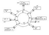
- FIG. 2represents a high level schematic of an embodiment of an ECCC according to the present invention.
- item 100represents any two way radio repeater [2-WAY REPEATER (i)]. These repeaters may be located in the same building or within different buildings within a geographic area that the system serves.
- the two way radio repeater 100is connected to a stand-alone console 101 [ECCC (i)].
- a typical repeateris manufactured by Motorola under the name QuantarTM Repeater, Model T5365A or by Tait Electronics under the name of TB9100.
- a remote Cell 120which may be used to monitor a tamper switch, indicating, e.g., forced entry into the repeater's equipment cabinet, or temperature sensor, or any other type of sensor as needed, may also be connected to the console 101 .
- Such physical media 110could be, for example, any fiber optical link, CAT-5x implementing a TCP/IP protocol, or an RS-485 twisted pair or any other type of media capable supporting a serially networked protocol for bidirectionally exchanging control data and or digitized audio signals.
- the physical media 110could be also implemented wirelessly by using any type of protocol, such as those implemented by IEEE 802.11a,b,g or zig-bee, etc.
- the primary physical ringmay also support the ability to operate in either direction if a single break occurs in the medium. This may be implemented using such technology as FDDI, Token Ring, SONET or appropriately configured IEEE 802.3 Ethernet type switches.
- a secondary physical media (redundant ring) 160represents a similar ring network as described with respect to the primary physical media 110 , but it is used for redundancy purposes. If primary physical media 110 is cut or physically destroyed, all communications protocols may executed by using the secondary physical media 160 .
- Multiple repeaters 100may each be connected to the primary ring 110 and the redundant ring 160 . Accordingly, each repeater may be able to utilize both rings.
- the rings 110 , 160 and/or any other redundant ringmay utilize the internet, allowing inter-location redundant systems implementations. In this way, emergency personnel can take over operation of a console from an independent location.
- the rings 110 , 160may utilize a WiFi or other wireless broadband network such as the broadband connectivity implemented by cellular phone carriers or a UMTS type network connection.
- a command control truckmay have a WiFi connection and may be able to connect into the rings.
- External stubs 190may be used to further extend the capabilities of additional communications redundant rings, whether on or off site. For example, when multiple rings are present, users may be able to connect to alternative rings over the internet.
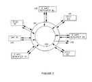
- FIG. 3shows a high level system overview of an ECCC based on embodiment of the present invention.
- a pair of fiber optic modems( 201 , 202 , 203 , 204 ) may be built into each console ( 1 , 2 ).
- the consolecommunicates with the repeaters over a fiber network.
- Bi-directional audio signalsare the outgoing and incoming voice.
- Bi-directional RS-232 lines( 205 , 206 ) provide repeater control and status.
- a switch contactis derived from the push-to-talk function and is used to key the transmitter.
- the consoleintermittently polls the repeaters to check their status. Since there are two or more repeaters, the ECCC selects one repeater as the default repeater ( 207 , 208 ). In the case of failure of the primary repeater, the ECCC automatically switches to the backup repeater ( 209 , 210 ).
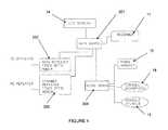
- FIG. 4shows a schematic of the internal configuration of an ECCC based on an embodiment of the present invention.
- the main board 301may be a central processing unit that consists of a microprocessor, memory and bulk storage and it is used to coordinate the functions of the other subsystems.
- the main boardconnects to the main repeater fiber optic modem 302 and the standby repeater fiber optic modem 303 .
- the fiber optic modems ( 302 , 303 )may consist of optical to electrical transceivers as well as multiplexers to combine the audio and control information into a single data stream. These modems also may implement communications protocols to assure reliable communication with each repeater.
- the main board 301also connects to the LCD display 14 which may consist of a display unit including a screen that implements a pixel field and a control unit to manage the operation of the display.
- the main boardalso interfaces to the recorder 11 which may include circuits to digitize the audio stream as well as tape, disk or semiconductor memory to store the audio information, and the audio board 304 which supports the physical connection to the phone handset 12 , the console microphone 18 , and the console speaker 15 .
Landscapes
- Engineering & Computer Science (AREA)
- Computer Networks & Wireless Communication (AREA)
- Signal Processing (AREA)
- Alarm Systems (AREA)
Abstract
Description
Claims (12)
Priority Applications (1)
| Application Number | Priority Date | Filing Date | Title |
|---|---|---|---|
| US13/409,535US9264100B1 (en) | 2007-12-19 | 2012-03-01 | Emergency communications controller and console |
Applications Claiming Priority (3)
| Application Number | Priority Date | Filing Date | Title |
|---|---|---|---|
| US824607P | 2007-12-19 | 2007-12-19 | |
| US12/337,864US8145125B2 (en) | 2007-12-19 | 2008-12-18 | Emergency communications controller and console |
| US13/409,535US9264100B1 (en) | 2007-12-19 | 2012-03-01 | Emergency communications controller and console |
Related Parent Applications (1)
| Application Number | Title | Priority Date | Filing Date |
|---|---|---|---|
| US12/337,864ContinuationUS8145125B2 (en) | 2007-12-19 | 2008-12-18 | Emergency communications controller and console |
Publications (1)
| Publication Number | Publication Date |
|---|---|
| US9264100B1true US9264100B1 (en) | 2016-02-16 |
Family
ID=42007656
Family Applications (2)
| Application Number | Title | Priority Date | Filing Date |
|---|---|---|---|
| US12/337,864Expired - Fee RelatedUS8145125B2 (en) | 2007-12-19 | 2008-12-18 | Emergency communications controller and console |
| US13/409,535Expired - Fee RelatedUS9264100B1 (en) | 2007-12-19 | 2012-03-01 | Emergency communications controller and console |
Family Applications Before (1)
| Application Number | Title | Priority Date | Filing Date |
|---|---|---|---|
| US12/337,864Expired - Fee RelatedUS8145125B2 (en) | 2007-12-19 | 2008-12-18 | Emergency communications controller and console |
Country Status (1)
| Country | Link |
|---|---|
| US (2) | US8145125B2 (en) |
Families Citing this family (11)
| Publication number | Priority date | Publication date | Assignee | Title |
|---|---|---|---|---|
| US8145125B2 (en) | 2007-12-19 | 2012-03-27 | Henry Bros. Electronics, Inc. | Emergency communications controller and console |
| US20120135677A1 (en)* | 2010-04-16 | 2012-05-31 | Samsung Electronics Co., Ltd. | Method and system for relay-initiated relay teardown operations in wireless communication networks |
| US9026044B2 (en) | 2010-04-16 | 2015-05-05 | Samsung Electronics Co., Ltd. | Method and system for responder-aware relay station selection in wireless communication networks |
| EP2466405A1 (en)* | 2010-12-15 | 2012-06-20 | Siemens Aktiengesellschaft | Control system for an industrial device with optional switching to different central units |
| US10419907B2 (en) | 2012-02-22 | 2019-09-17 | Qualcomm Incorporated | Proximity application discovery and provisioning |
| US9544075B2 (en) | 2012-02-22 | 2017-01-10 | Qualcomm Incorporated | Platform for wireless identity transmitter and system using short range wireless broadcast |
| US10360593B2 (en) | 2012-04-24 | 2019-07-23 | Qualcomm Incorporated | Retail proximity marketing |
| US8923755B2 (en) | 2012-04-29 | 2014-12-30 | Techmer Ltd. | Radio repeater system |
| US8990556B1 (en) | 2014-08-13 | 2015-03-24 | Gimbal, Inc. | Sharing beacons |
| US9107152B1 (en) | 2015-03-11 | 2015-08-11 | Gimbal, Inc. | Beacon protocol advertising bi-directional communication availability window |
| US10757237B2 (en)* | 2018-01-12 | 2020-08-25 | RF Solutions, LLC | Configurable communications apparatus and kit |
Citations (5)
| Publication number | Priority date | Publication date | Assignee | Title |
|---|---|---|---|---|
| US5815799A (en)* | 1989-03-31 | 1998-09-29 | E.F. Johnson Company | Priority system for a wide area transmission trunked communication system |
| US7751806B1 (en)* | 2005-12-07 | 2010-07-06 | Nextel Communications Inc. | System and method for monitoring dispatch communications |
| US20110276326A1 (en)* | 2010-05-06 | 2011-11-10 | Motorola, Inc. | Method and system for operational improvements in dispatch console systems in a multi-source environment |
| US8145125B2 (en) | 2007-12-19 | 2012-03-27 | Henry Bros. Electronics, Inc. | Emergency communications controller and console |
| US8446847B2 (en)* | 2007-03-26 | 2013-05-21 | Huawei Technologies Co., Ltd. | System, device and method for implementing special call service |
Family Cites Families (23)
| Publication number | Priority date | Publication date | Assignee | Title |
|---|---|---|---|---|
| US3800089A (en) | 1972-02-24 | 1974-03-26 | Itt | Hands-free emergency telephone system |
| US3939417A (en) | 1973-12-18 | 1976-02-17 | Motorola, Inc. | Emergency communications system |
| US4176254A (en) | 1977-12-27 | 1979-11-27 | Telcom, Inc. | Emergency roadside telephone system |
| US5274838A (en) | 1987-06-03 | 1993-12-28 | Ericsson Ge Mobile Communications Inc. | Fail-soft architecture for public trunking system |
| US5363436A (en) | 1989-10-02 | 1994-11-08 | Mcmonagle Jr John J | Remotely programmable, vandal-resistant voice communications unit |
| US5086463A (en) | 1989-10-02 | 1992-02-04 | Vesely Kevin T | Vandal-resistant communications station |
| US5105460A (en) | 1991-03-11 | 1992-04-14 | Williams John S | Plug-in telephone facility |
| US5283546A (en) | 1991-05-13 | 1994-02-01 | Motorola, Inc. | Vandal-resistant call box |
| US5343509A (en) | 1991-08-30 | 1994-08-30 | Dounies Gregory F | Emergency information facsimile transmitter |
| USD358153S (en) | 1993-12-20 | 1995-05-09 | Jackson Glenn D | Two-way emergency communication system |
| US5752198A (en) | 1994-11-14 | 1998-05-12 | Ericsson Inc. | Single site, split location trunked radio communications system |
| US5784456A (en) | 1995-06-29 | 1998-07-21 | Cyracom International, Inc. | Single-line multi-handset telephone |
| US6060979A (en) | 1995-12-11 | 2000-05-09 | Eichsteadt; Gary | Call box apparatus |
| US5963631A (en) | 1996-07-16 | 1999-10-05 | National Railroad Passenger Corporation | Wayside communications safety system |
| US6529486B1 (en)* | 1997-04-11 | 2003-03-04 | Transcrypt International/E.F. Johnson Company | Trunked radio repeater communication system |
| US6614883B2 (en) | 1999-03-31 | 2003-09-02 | Elliot Baum | Emergency call system |
| US7480501B2 (en) | 2001-10-24 | 2009-01-20 | Statsignal Ipc, Llc | System and method for transmitting an emergency message over an integrated wireless network |
| GB0200237D0 (en)* | 2002-01-07 | 2002-02-20 | Imec Inter Uni Micro Electr | Wireless cellular network architecture |
| US20040086092A1 (en) | 2002-07-09 | 2004-05-06 | Fehr Van Kirk | Method and system for emergency communication for high risk residents |
| US6996392B2 (en) | 2002-09-03 | 2006-02-07 | Trueposition, Inc. | E911 overlay solution for GSM, for use in a wireless location system |
| US20050172304A1 (en) | 2003-11-28 | 2005-08-04 | David Tavares | Event management system |
| JP4625712B2 (en)* | 2005-04-14 | 2011-02-02 | パナソニック株式会社 | Semiconductor integrated circuit and electronic equipment |
| US20080085696A1 (en) | 2006-10-10 | 2008-04-10 | Salahshour Chad S | Emergency communication system utilizing available radio frequencies and telephone lines |
- 2008
- 2008-12-18USUS12/337,864patent/US8145125B2/ennot_activeExpired - Fee Related
- 2012
- 2012-03-01USUS13/409,535patent/US9264100B1/ennot_activeExpired - Fee Related
Patent Citations (5)
| Publication number | Priority date | Publication date | Assignee | Title |
|---|---|---|---|---|
| US5815799A (en)* | 1989-03-31 | 1998-09-29 | E.F. Johnson Company | Priority system for a wide area transmission trunked communication system |
| US7751806B1 (en)* | 2005-12-07 | 2010-07-06 | Nextel Communications Inc. | System and method for monitoring dispatch communications |
| US8446847B2 (en)* | 2007-03-26 | 2013-05-21 | Huawei Technologies Co., Ltd. | System, device and method for implementing special call service |
| US8145125B2 (en) | 2007-12-19 | 2012-03-27 | Henry Bros. Electronics, Inc. | Emergency communications controller and console |
| US20110276326A1 (en)* | 2010-05-06 | 2011-11-10 | Motorola, Inc. | Method and system for operational improvements in dispatch console systems in a multi-source environment |
Also Published As
| Publication number | Publication date |
|---|---|
| US20100068992A1 (en) | 2010-03-18 |
| US8145125B2 (en) | 2012-03-27 |
Similar Documents
| Publication | Publication Date | Title |
|---|---|---|
| US9264100B1 (en) | Emergency communications controller and console | |
| US10600315B2 (en) | Mesh network enabled building safety system and method | |
| CA2274572A1 (en) | Security alarm system | |
| WO2005077077B1 (en) | Systems and methods for a personal safety device | |
| US20120188067A1 (en) | Alarm Sound Activated Module for Remote Notification | |
| JP2011504312A (en) | Child protection management system and method using wireless communication network | |
| GB2363028A (en) | Surveillance system with remote receiving unit. | |
| JP2007174542A (en) | Condominium intercom system | |
| KR20010068717A (en) | Digital video security apparatus | |
| US20120262289A1 (en) | Security systems having portable monitoring devices and methods using same | |
| KR100913310B1 (en) | Emergency alarm system | |
| EP2884723B1 (en) | Wireless communication apparatus, wireless communication system, and data processing method | |
| KR20010064587A (en) | Security radio relay system and control method therefor | |
| KR101017681B1 (en) | Digital network broadcasting system | |
| CN101930658B (en) | Monitoring alarm method, equipment and system | |
| JP4187493B2 (en) | TV door phone | |
| JP2008236650A (en) | Regional disaster prevention radio system | |
| EP0973345A2 (en) | Apparatus and method for transmitting and registering calls for assistance | |
| JP2002183851A (en) | Remote monitoring device | |
| US6618582B1 (en) | Customer service system with feedback and method for operating | |
| JP2001093066A (en) | Security system or fire fighting system | |
| JP3105812B2 (en) | Outdoor loudspeaker for disaster prevention administrative radio system and outdoor loudspeaker method | |
| TW466461B (en) | Digital wireless video/audio security system | |
| JP4981465B2 (en) | Intercom system, intercom master unit and fire alarm | |
| JP2003298772A (en) | Support system for disaster-preventing facilities |
Legal Events
| Date | Code | Title | Description |
|---|---|---|---|
| AS | Assignment | Owner name:HENRY BROS. ELECTRONICS, INC., CALIFORNIA Free format text:ASSIGNMENT OF ASSIGNORS INTEREST;ASSIGNOR:MASOIAN, LEE;REEL/FRAME:027974/0819 Effective date:20120215 | |
| AS | Assignment | Owner name:WILMINGTON TRUST, NATIONAL ASSOCIATION, MINNESOTA Free format text:SECURITY INTEREST;ASSIGNORS:AIRORLITE COMMUNICATIONS, INC.;CHARLESTON MARINE CONTAINERS INC.;COMPOSITE ENGINEERING, INC.;AND OTHERS;REEL/FRAME:034861/0796 Effective date:20140514 | |
| SULP | Surcharge for late payment | ||
| STCF | Information on status: patent grant | Free format text:PATENTED CASE | |
| AS | Assignment | Owner name:KRATOS DEFENSE & SECURITY SOLUTIONS, INC., CALIFOR Free format text:RELEASE BY SECURED PARTY;ASSIGNOR:WILMINGTON TRUST, NATIONAL ASSOCIATION;REEL/FRAME:044195/0924 Effective date:20171120 Owner name:KRATOS TECHNOLOGY & TRAINING SOLUTIONS, INC., CALI Free format text:RELEASE BY SECURED PARTY;ASSIGNOR:WILMINGTON TRUST, NATIONAL ASSOCIATION;REEL/FRAME:044195/0924 Effective date:20171120 Owner name:SECUREINFO CORPORATION, CALIFORNIA Free format text:RELEASE BY SECURED PARTY;ASSIGNOR:WILMINGTON TRUST, NATIONAL ASSOCIATION;REEL/FRAME:044195/0924 Effective date:20171120 Owner name:KRATOS UNMANNED AERIAL SYSTEMS, INC., CALIFORNIA Free format text:RELEASE BY SECURED PARTY;ASSIGNOR:WILMINGTON TRUST, NATIONAL ASSOCIATION;REEL/FRAME:044195/0924 Effective date:20171120 Owner name:GENERAL MICROWAVE CORPORATION, CALIFORNIA Free format text:RELEASE BY SECURED PARTY;ASSIGNOR:WILMINGTON TRUST, NATIONAL ASSOCIATION;REEL/FRAME:044195/0924 Effective date:20171120 Owner name:AIRORLITE COMMUNICATIONS, INC., CALIFORNIA Free format text:RELEASE BY SECURED PARTY;ASSIGNOR:WILMINGTON TRUST, NATIONAL ASSOCIATION;REEL/FRAME:044195/0924 Effective date:20171120 Owner name:DIGITAL FUSION, INC., CALIFORNIA Free format text:RELEASE BY SECURED PARTY;ASSIGNOR:WILMINGTON TRUST, NATIONAL ASSOCIATION;REEL/FRAME:044195/0924 Effective date:20171120 Owner name:CHARLESTON MARINE CONTAINERS INC., CALIFORNIA Free format text:RELEASE BY SECURED PARTY;ASSIGNOR:WILMINGTON TRUST, NATIONAL ASSOCIATION;REEL/FRAME:044195/0924 Effective date:20171120 Owner name:HENRY BROS. ELECTRONICS, INC., CALIFORNIA Free format text:RELEASE BY SECURED PARTY;ASSIGNOR:WILMINGTON TRUST, NATIONAL ASSOCIATION;REEL/FRAME:044195/0924 Effective date:20171120 Owner name:KRATOS INTEGRAL HOLDINGS, LLC, CALIFORNIA Free format text:RELEASE BY SECURED PARTY;ASSIGNOR:WILMINGTON TRUST, NATIONAL ASSOCIATION;REEL/FRAME:044195/0924 Effective date:20171120 | |
| AS | Assignment | Owner name:WILMINGTON TRUST, NATIONAL ASSOCIATION, AS COLLATE Free format text:SECURITY INTEREST;ASSIGNORS:AIRORLITE COMMUNICATIONS, INC.;CHARLESTON MARINE CONTAINERS, INC.;DIGITAL FUSION, INC.;AND OTHERS;REEL/FRAME:044593/0678 Effective date:20171120 | |
| AS | Assignment | Owner name:SUNTRUST BANK, GEORGIA Free format text:AMENDED AND RESTATED INTELLECTUAL PROPERTY SECURITY AGREEMENT;ASSIGNORS:KRATOS DEFENSE & SECURITY SOLUTIONS, INC.;AI METRIX, INC.;AIRORLITE COMMUNICATIONS, INC.;AND OTHERS;REEL/FRAME:044742/0845 Effective date:20171120 | |
| FEPP | Fee payment procedure | Free format text:MAINTENANCE FEE REMINDER MAILED (ORIGINAL EVENT CODE: REM.); ENTITY STATUS OF PATENT OWNER: LARGE ENTITY | |
| LAPS | Lapse for failure to pay maintenance fees | Free format text:PATENT EXPIRED FOR FAILURE TO PAY MAINTENANCE FEES (ORIGINAL EVENT CODE: EXP.); ENTITY STATUS OF PATENT OWNER: LARGE ENTITY | |
| STCH | Information on status: patent discontinuation | Free format text:PATENT EXPIRED DUE TO NONPAYMENT OF MAINTENANCE FEES UNDER 37 CFR 1.362 | |
| FP | Lapsed due to failure to pay maintenance fee | Effective date:20200216 | |
| AS | Assignment | Owner name:SAT CORPORATION, CALIFORNIA Free format text:RELEASE BY SECURED PARTY;ASSIGNOR:WILMINGTON TRUST, NATIONAL ASSOCIATION, AS COLLATERAL AGENT;REEL/FRAME:059616/0001 Effective date:20220218 Owner name:KRATOS UNMANNED AERIAL SYSTEMS, INC. (F/K/A COMPOSITE ENGINEERING INC.), CALIFORNIA Free format text:RELEASE BY SECURED PARTY;ASSIGNOR:WILMINGTON TRUST, NATIONAL ASSOCIATION, AS COLLATERAL AGENT;REEL/FRAME:059616/0001 Effective date:20220218 Owner name:KRATOS TECHNOLOGY & TRAINING SOLUTIONS, INC., CALIFORNIA Free format text:RELEASE BY SECURED PARTY;ASSIGNOR:WILMINGTON TRUST, NATIONAL ASSOCIATION, AS COLLATERAL AGENT;REEL/FRAME:059616/0001 Effective date:20220218 Owner name:KRATOS INTEGRAL HOLDINGS, LLC, CALIFORNIA Free format text:RELEASE BY SECURED PARTY;ASSIGNOR:WILMINGTON TRUST, NATIONAL ASSOCIATION, AS COLLATERAL AGENT;REEL/FRAME:059616/0001 Effective date:20220218 Owner name:DIGITAL FUSION, INC., ALABAMA Free format text:RELEASE BY SECURED PARTY;ASSIGNOR:WILMINGTON TRUST, NATIONAL ASSOCIATION, AS COLLATERAL AGENT;REEL/FRAME:059616/0001 Effective date:20220218 Owner name:CHARLESTON MARINE CONTAINERS, INC., CALIFORNIA Free format text:RELEASE BY SECURED PARTY;ASSIGNOR:WILMINGTON TRUST, NATIONAL ASSOCIATION, AS COLLATERAL AGENT;REEL/FRAME:059616/0001 Effective date:20220218 Owner name:SECUREINFO CORPORATION, VIRGINIA Free format text:RELEASE BY SECURED PARTY;ASSIGNOR:TRUIST BANK, SUCCESSOR BY MERGER TO SUNTRUST BANK, AS COLLATERAL AGENT AND ADMINISTRATIVE AGENT;REEL/FRAME:059616/0151 Effective date:20220218 Owner name:MICRO SYSTEMS, INC., FLORIDA Free format text:RELEASE BY SECURED PARTY;ASSIGNOR:TRUIST BANK, SUCCESSOR BY MERGER TO SUNTRUST BANK, AS COLLATERAL AGENT AND ADMINISTRATIVE AGENT;REEL/FRAME:059616/0151 Effective date:20220218 Owner name:GICHNER SYTEMS GROUP, INC., PENNSYLVANIA Free format text:RELEASE BY SECURED PARTY;ASSIGNOR:TRUIST BANK, SUCCESSOR BY MERGER TO SUNTRUST BANK, AS COLLATERAL AGENT AND ADMINISTRATIVE AGENT;REEL/FRAME:059616/0151 Effective date:20220218 Owner name:KRATOS UNMANNED AERIAL SYSTEMS, INC. (F/K/A COMPOSITE ENGINEERING, INC.), CALIFORNIA Free format text:RELEASE BY SECURED PARTY;ASSIGNOR:TRUIST BANK, SUCCESSOR BY MERGER TO SUNTRUST BANK, AS COLLATERAL AGENT AND ADMINISTRATIVE AGENT;REEL/FRAME:059616/0151 Effective date:20220218 Owner name:DIGITAL FUSION, INC., ALABAMA Free format text:RELEASE BY SECURED PARTY;ASSIGNOR:TRUIST BANK, SUCCESSOR BY MERGER TO SUNTRUST BANK, AS COLLATERAL AGENT AND ADMINISTRATIVE AGENT;REEL/FRAME:059616/0151 Effective date:20220218 Owner name:CHARLESTON MARINE CONTAINERS, INC., CALIFORNIA Free format text:RELEASE BY SECURED PARTY;ASSIGNOR:TRUIST BANK, SUCCESSOR BY MERGER TO SUNTRUST BANK, AS COLLATERAL AGENT AND ADMINISTRATIVE AGENT;REEL/FRAME:059616/0151 Effective date:20220218 Owner name:KRATOS TECHNOLOGY & TRAINING SOLUTIONS, INC., CALIFORNIA Free format text:RELEASE BY SECURED PARTY;ASSIGNOR:TRUIST BANK, SUCCESSOR BY MERGER TO SUNTRUST BANK, AS COLLATERAL AGENT AND ADMINISTRATIVE AGENT;REEL/FRAME:059616/0151 Effective date:20220218 Owner name:SAT CORPORATION, CALIFORNIA Free format text:RELEASE BY SECURED PARTY;ASSIGNOR:TRUIST BANK, SUCCESSOR BY MERGER TO SUNTRUST BANK, AS COLLATERAL AGENT AND ADMINISTRATIVE AGENT;REEL/FRAME:059616/0151 Effective date:20220218 Owner name:KRATOS INTEGRAL HOLDINGS, LLC, CALIFORNIA Free format text:RELEASE BY SECURED PARTY;ASSIGNOR:TRUIST BANK, SUCCESSOR BY MERGER TO SUNTRUST BANK, AS COLLATERAL AGENT AND ADMINISTRATIVE AGENT;REEL/FRAME:059616/0151 Effective date:20220218 |