US9263964B1 - Systems and methods for low-power lamp compatibility with an electronic transformer - Google Patents
Systems and methods for low-power lamp compatibility with an electronic transformerDownload PDFInfo
- Publication number
- US9263964B1 US9263964B1US13/972,102US201313972102AUS9263964B1US 9263964 B1US9263964 B1US 9263964B1US 201313972102 AUS201313972102 AUS 201313972102AUS 9263964 B1US9263964 B1US 9263964B1
- Authority
- US
- United States
- Prior art keywords
- voltage
- power converter
- storage device
- energy storage
- electronic transformer
- Prior art date
- Legal status (The legal status is an assumption and is not a legal conclusion. Google has not performed a legal analysis and makes no representation as to the accuracy of the status listed.)
- Active, expires
Links
Images


Classifications
- H—ELECTRICITY
- H02—GENERATION; CONVERSION OR DISTRIBUTION OF ELECTRIC POWER
- H02M—APPARATUS FOR CONVERSION BETWEEN AC AND AC, BETWEEN AC AND DC, OR BETWEEN DC AND DC, AND FOR USE WITH MAINS OR SIMILAR POWER SUPPLY SYSTEMS; CONVERSION OF DC OR AC INPUT POWER INTO SURGE OUTPUT POWER; CONTROL OR REGULATION THEREOF
- H02M7/00—Conversion of AC power input into DC power output; Conversion of DC power input into AC power output
- H02M7/02—Conversion of AC power input into DC power output without possibility of reversal
- H02M7/04—Conversion of AC power input into DC power output without possibility of reversal by static converters
- H02M7/06—Conversion of AC power input into DC power output without possibility of reversal by static converters using discharge tubes without control electrode or semiconductor devices without control electrode
- H—ELECTRICITY
- H02—GENERATION; CONVERSION OR DISTRIBUTION OF ELECTRIC POWER
- H02M—APPARATUS FOR CONVERSION BETWEEN AC AND AC, BETWEEN AC AND DC, OR BETWEEN DC AND DC, AND FOR USE WITH MAINS OR SIMILAR POWER SUPPLY SYSTEMS; CONVERSION OF DC OR AC INPUT POWER INTO SURGE OUTPUT POWER; CONTROL OR REGULATION THEREOF
- H02M1/00—Details of apparatus for conversion
- H02M1/36—Means for starting or stopping converters
- H05B33/0809—
- H—ELECTRICITY
- H05—ELECTRIC TECHNIQUES NOT OTHERWISE PROVIDED FOR
- H05B—ELECTRIC HEATING; ELECTRIC LIGHT SOURCES NOT OTHERWISE PROVIDED FOR; CIRCUIT ARRANGEMENTS FOR ELECTRIC LIGHT SOURCES, IN GENERAL
- H05B45/00—Circuit arrangements for operating light-emitting diodes [LED]
- H05B45/30—Driver circuits
- H05B45/37—Converter circuits
- H05B45/3725—Switched mode power supply [SMPS]
- H05B45/38—Switched mode power supply [SMPS] using boost topology
- H—ELECTRICITY
- H05—ELECTRIC TECHNIQUES NOT OTHERWISE PROVIDED FOR
- H05B—ELECTRIC HEATING; ELECTRIC LIGHT SOURCES NOT OTHERWISE PROVIDED FOR; CIRCUIT ARRANGEMENTS FOR ELECTRIC LIGHT SOURCES, IN GENERAL
- H05B45/00—Circuit arrangements for operating light-emitting diodes [LED]
- H05B45/30—Driver circuits
- H05B45/37—Converter circuits
- H05B45/3725—Switched mode power supply [SMPS]
- H05B45/382—Switched mode power supply [SMPS] with galvanic isolation between input and output
- H—ELECTRICITY
- H02—GENERATION; CONVERSION OR DISTRIBUTION OF ELECTRIC POWER
- H02M—APPARATUS FOR CONVERSION BETWEEN AC AND AC, BETWEEN AC AND DC, OR BETWEEN DC AND DC, AND FOR USE WITH MAINS OR SIMILAR POWER SUPPLY SYSTEMS; CONVERSION OF DC OR AC INPUT POWER INTO SURGE OUTPUT POWER; CONTROL OR REGULATION THEREOF
- H02M1/00—Details of apparatus for conversion
- H02M1/0003—Details of control, feedback or regulation circuits
- H02M1/0006—Arrangements for supplying an adequate voltage to the control circuit of converters
Definitions
- the present disclosurerelates in general to the field of electronics, and more specifically to systems and methods for ensuring compatibility between one or more low-power lamps and the power infrastructure to which they are coupled.
- low-power lightingemploys halogen light bulbs, light-emitting diode light bulbs, compact fluorescent light bulbs, or other types of light bulbs or lamp assemblies that produce light with intensity on par with that of traditional incandescent light bulbs, but with significantly less power consumption.
- many of such light bulbs or lamp assembliesoperate using a voltage (e.g., 12 volts) much less than that typically provided by traditional power infrastructures.
- a voltage transformermust be interposed between the public electricity source and the lamp assembly.
- Transformers present in a power infrastructuremay include magnetic or electronic transformers.
- a magnetic transformertypically comprises two coils of conductive material (e.g., copper) each wrapped around a core of material having a high magnetic permeability (e.g., iron) such that magnetic flux passes through both coils.
- an electric current in the first coilmay produce a changing magnetic field in the core, such that the changing magnetic field induces a voltage across the ends of the secondary winding via electromagnetic induction.
- a magnetic transformermay step voltage levels up or down while providing electrical isolation in a circuit between components coupled to the primary winding and components coupled to the secondary winding.
- an electronic transformeris a device which behaves in the same manner as a conventional magnetic transformer in that it steps voltage levels up or down while providing isolation and can accommodate load current of any power factor.
- An electronic transformergenerally includes power switches which convert a low-frequency (e.g., direct current to 400 Hertz) voltage wave to a high-frequency voltage wave (e.g., in the order of 10,000 Hertz).
- a comparatively small magnetic transformermay be coupled to such power switches and thus provides the voltage level transformation and isolation functions of the conventional magnetic transformer.
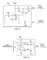
- FIG. 1depicts a lighting system 101 that includes an electronic transformer 122 and a lamp assembly 142 .
- a systemmay be used, for example, to transform a high voltage (e.g., 110V, 220 V) to a low voltage (e.g., 12 V) for use with a halogen lamp (e.g., an MR16 halogen lamp).
- a transformer 122may be present in a lighting fixture configured to receive a lamp assembly 142 , wherein such lamp assembly 142 includes a source of light (e.g., LEDs 152 ) for providing illumination.
- a transformer 122 designed to receive an incandescent or halogen lamp assembly“expects” a linear load (e.g., one which has a primarily constant impedance, in which current varies in a linear fashion with the voltage applied to the load).
- a linear loade.g., one which has a primarily constant impedance, in which current varies in a linear fashion with the voltage applied to the load.
- a lamp that has a non-linear operating modee.g., including but not limited to a light-emitting diode, or LED, lamp
- the electronic transformermay not function properly, due to the fact that the non-linear load may present widely varying impedances for different time durations.
- an electronic transformer 122may have a power rating range, such as from a minimum power rating to a maximum power rating (e.g., zero watts to 60 watts).
- a power rating rangesuch as from a minimum power rating to a maximum power rating (e.g., zero watts to 60 watts).
- lighting system 101may receive an AC supply voltage V SUPPLY from voltage supply 104 .
- the supply voltage V SUPPLYis, for example, a nominally 60 Hz/110 V line voltage in the United States of America or a nominally 50 Hz/220 V line voltage in Europe.
- Electronic transformer 122may receive the AC supply voltage V SUPPLY at its input where it is rectified by a full-bridge rectifier formed by diodes 124 . As voltage V SUPPLY increases in magnitude, voltage on capacitor 126 may increase to a point where diac 128 will turn on (the diac break-over voltage), thus also turning on transistor 129 .
- switching transformer 130may be a saturable core transformer, and if the impedance of lamp assembly 142 is too low, the core of switching transformer 130 may saturate causing the voltage across the base-emitter junction of transistor 129 to go to zero, thus turning off transistor 129 .
- the load presented to transformer 122 by lamp 142must be low enough that the current through switching transformer 130 at the break-over voltage of diac 128 will saturate switching transformer 130 , causing it to oscillate.
- Lamp assembly 142may receive the AC supply voltage V S at its input where it is rectified by a full-bridge rectifier formed by diodes 144 . Such voltage may charge a capacitor 146 , thus providing a direct current voltage V DD for power converter 148 .
- Power converter 148may be operable to provide a regulated voltage V LINK to LED driver 150 , which itself may include circuitry for driving an output voltage or current to LEDs 152 , thus generating photonic energy.
- capacitor 146needs to charge to a voltage V DD sufficient to allow power converter 148 and LED driver 150 to begin steady-state operation.
- capacitor 146is the primary load to electronic transformer 122 while power converter 148 and LED driver 150 start-up, a non-linear load is provided to electronic transformer 122 .
- capacitor 146Upon start-up of electronic transformer 122 , capacitor 146 initially provides a low impedance to electronic transformer 122 , and electronic transformer 122 may begin oscillating. However, when capacitor 146 reaches a voltage V DD equal to a diode threshold voltage below the peak voltage value from electronic transformer 122 , capacitor 146 then presents a high impedance to electronic transformer 122 , and electronic transformer 122 may stop oscillation. If the voltage V DD across capacitor 146 is less than the steady-state voltage of power converter 148 , then lamp assembly 142 may fail to present a linear load to electronic transformer 122 .
- an apparatus for providing compatibility between a load having a reactive impedance and a secondary winding of an electronic transformermay include a power converter and a circuit.
- the power convertermay be configured to transfer electrical energy from the secondary winding to the load.
- the circuitmay be configured to charge an energy storage device coupled to the power converter following start-up of the electronic transformer in order to increase a voltage of the energy storage device to at least a voltage level sufficient for the power converter to enter steady-state operation.
- a method for providing compatibility between a load having a reactive impedance and a secondary winding of an electronic transformermay include charging an energy storage device coupled to a power converter following start-up of the electronic transformer in order to increase a voltage of the energy storage device to at least a voltage level sufficient for the power converter to enter steady-state operation.
- FIG. 1illustrates a lighting system that includes an electronic transformer, as is known in the art
- FIGS. 2A and 2Billustrate example lamp assemblies including circuitry for providing compatibility between the lamp assembly and other elements of a lighting system, in accordance with embodiments of the present disclosure
- FIG. 3illustrates an example voltage boost circuit for use in the example lamp assemblies of FIGS. 2A and 2B , in accordance with embodiments of the present disclosure
- FIGS. 4A and 4Billustrate additional example lamp assemblies including circuitry for providing compatibility between the lamp assembly and other elements of a lighting system, in accordance with embodiments of the present disclosure.
- FIG. 5illustrates an example voltage boost circuit for use in the example lamp assemblies of FIGS. 4A and 4B , in accordance with embodiments of the present disclosure.
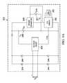
- FIGS. 2A and 2Billustrate example lamp assemblies 242 including circuitry for providing compatibility between lamp assembly 242 and other elements of a lighting system (e.g., an electronic transformer), in accordance with embodiments of the present disclosure.
- a lighting systeme.g., an electronic transformer
- a lamp assembly 242may include charging capacitor 246 which, during operation of such lamp assembly 242 , charges as a result of energy transferred from the input of such lamp assembly 242 to a direct current voltage V DD for powering power converter 248 .
- Power converter 248may comprise any system, device, or apparatus for providing a regulated, direct current voltage V LINK on capacitor 247 to LED driver 250 .
- power converter 248may comprise a boost converter.
- LED driver 250may comprise any system, device, or apparatus for driving an output voltage to light-emitting diodes (LEDs) 252 or another light source.
- capacitor 246 and power converter 248may, in the absence of circuitry for providing compatibility between a lamp assembly 242 and other elements of a lighting system (e.g., an electronic transformer), present as a load having a non-linear reactive impedance to components of a lighting system coupled at the input terminals of a lamp assembly 242 , which, as described in the “Background” section above, may lead to improper or undesirable operation of lamp assembly 242 .
- a lighting systeme.g., an electronic transformer
- a lamp assembly 242 as depicted in either of FIG. 2A or 2 Bmay include a voltage boost circuit 220 .
- Voltage boost circuit 220may be any system, device, or apparatus for charging an energy storage device coupled to power converter 248 (e.g., a capacitor such as capacitor 246 as shown in FIG. 2A or capacitor 247 as shown in FIG.
- voltage boost circuit 220may cease charging the energy storage device.
- a control signalfor example control signal CTRL shown as generated by LED driver 250 in FIGS. 2A and 2B , may indicate that the voltage of the energy storage device has reached the voltage threshold, and thus voltage boost circuit 220 may cease charging the energy storage device in response to such control signal.
- the voltage thresholdmay be greater than or approximately equal to a voltage for V LINK sufficient for LED driver 250 to drive LEDs 252 .
- the voltage thresholdmay be greater than or approximately equal to a voltage V DD sufficient for power converter 248 to drive an output voltage V LINK sufficient for LED driver 250 to drive LEDs 252 .
- voltage boost circuit 220may then take over driving the load and presenting the load to the electronic transformer.
- voltage boost circuit 220may ensure proper operation of power converter 248 during start-up, and then allow transition to steady-state operation of the power converter 248 .
- FIG. 3illustrates an example voltage boost circuit 220 for use in the example lamp assemblies of FIGS. 2A and 2B , in accordance with embodiments of the present disclosure.
- a ring oscillator formed by inverter 302 , resistor 304 , and capacitor 306may drive a voltage doubler formed by diodes 312 and 314 and capacitor 316 .
- the supply voltage for the ring oscillator and voltage doublermay be the rectified secondary winding voltage V RECT as generated by the bridge rectifier formed by diodes 244 .
- the ring oscillatormay be selectively enabled by a control signal (e.g., control signal CTRL generated by LED driver 250 ) such that when the voltage V LINK of the load has reached the voltage threshold, the ring oscillator may be disabled and voltage boost circuit 220 may cease charging the energy storage device in response to such control signal.
- a control signale.g., control signal CTRL generated by LED driver 250
- voltage boost circuit 220may be implemented in any manner suitable for performing the functionality described herein.
- voltage boost circuit 220may comprise an inductor-based boost circuit.
- FIGS. 4A and 4Billustrate additional example lamp assemblies 242 including circuitry for providing compatibility between the lamp assembly and other elements of a lighting system, in accordance with embodiments of the present disclosure.
- the example lamp assemblies 242 disclosed in FIGS. 4A and 4Bare similar in structure and functionality to those example lamp assemblies 242 disclosed in FIGS. 2A and 2B , and accordingly, only substantive differences in FIGS. 4A and 4B as compared to FIGS. 2A and 2B are described below.
- a voltage boost circuit 420is supplied by the unrectified secondary winding voltage V S , rather than by the rectified secondary winding voltage V RECT .
- FIG. 5illustrates an example voltage boost circuit 420 for use in the example lamp assemblies of FIGS. 4A and 4B , in accordance with embodiments of the present disclosure.
- the electronic secondary winding voltage V Smay provide oscillation for driving a voltage doubler formed by capacitors 502 and 504 , as rectified by diodes 506 , 508 , 510 , and 512 .
- the output voltage VOUTmay drive either of voltage VDD or VLINK, in order to provide compatibility between the load of lamp assembly 242 and an electronic transformer by charging an energy storage device coupled to power converter 248 (e.g., a capacitor such as capacitor 246 as shown in FIG. 4A or capacitor 247 as shown in FIG.
- power converter 248e.g., a capacitor such as capacitor 246 as shown in FIG. 4A or capacitor 247 as shown in FIG.
- references in the appended claims to an apparatus or system or a component of an apparatus or system being adapted to, arranged to, capable of, configured to, enabled to, operable to, or operative to perform a particular functionencompasses that apparatus, system, or component, whether or not it or that particular function is activated, turned on, or unlocked, as long as that apparatus, system, or component is so adapted, arranged, capable, configured, enabled, operable, or operative.
Landscapes
- Engineering & Computer Science (AREA)
- Power Engineering (AREA)
- Circuit Arrangement For Electric Light Sources In General (AREA)
Abstract
Description
Claims (16)
Priority Applications (1)
| Application Number | Priority Date | Filing Date | Title |
|---|---|---|---|
| US13/972,102US9263964B1 (en) | 2013-03-14 | 2013-08-21 | Systems and methods for low-power lamp compatibility with an electronic transformer |
Applications Claiming Priority (2)
| Application Number | Priority Date | Filing Date | Title |
|---|---|---|---|
| US201361782305P | 2013-03-14 | 2013-03-14 | |
| US13/972,102US9263964B1 (en) | 2013-03-14 | 2013-08-21 | Systems and methods for low-power lamp compatibility with an electronic transformer |
Publications (1)
| Publication Number | Publication Date |
|---|---|
| US9263964B1true US9263964B1 (en) | 2016-02-16 |
Family
ID=55275523
Family Applications (1)
| Application Number | Title | Priority Date | Filing Date |
|---|---|---|---|
| US13/972,102Active2034-05-19US9263964B1 (en) | 2013-03-14 | 2013-08-21 | Systems and methods for low-power lamp compatibility with an electronic transformer |
Country Status (1)
| Country | Link |
|---|---|
| US (1) | US9263964B1 (en) |
Cited By (1)
| Publication number | Priority date | Publication date | Assignee | Title |
|---|---|---|---|---|
| CN107995736A (en)* | 2017-12-15 | 2018-05-04 | 矽力杰半导体技术(杭州)有限公司 | LED drive circuit, power inverter and control method |
Citations (78)
| Publication number | Priority date | Publication date | Assignee | Title |
|---|---|---|---|---|
| US3806829A (en) | 1971-04-13 | 1974-04-23 | Sys Inc | Pulsed laser system having improved energy control with improved power supply laser emission energy sensor and adjustable repetition rate control features |
| US4008414A (en) | 1975-07-28 | 1977-02-15 | Power Saver Corporation | Circuit for powering fluorescent lamps |
| US4562382A (en) | 1982-11-26 | 1985-12-31 | Quietlite International Ltd. | Solid-state inverter including a multiple core transformer |
| US5040236A (en) | 1990-07-18 | 1991-08-13 | Argus International | Apparatus for irradiation of printed wiring boards and the like |
| US5089753A (en) | 1990-07-09 | 1992-02-18 | North American Philips Corporation | Arrangement for predicting failure in fluorescent lamp systems |
| US5416387A (en) | 1993-11-24 | 1995-05-16 | California Institute Of Technology | Single stage, high power factor, gas discharge lamp ballast |
| US5583402A (en) | 1994-01-31 | 1996-12-10 | Magnetek, Inc. | Symmetry control circuit and method |
| US5650694A (en) | 1995-03-31 | 1997-07-22 | Philips Electronics North America Corporation | Lamp controller with lamp status detection and safety circuitry |
| US5872429A (en) | 1995-03-31 | 1999-02-16 | Philips Electronics North America Corporation | Coded communication system and method for controlling an electric lamp |
| US6369461B1 (en)* | 2000-09-01 | 2002-04-09 | Abb Inc. | High efficiency power conditioner employing low voltage DC bus and buck and boost converters |
| US6407935B1 (en) | 2000-05-30 | 2002-06-18 | Koninklijke Philips Electronics N.V. | High frequency electronic ballast with reactive power compensation |
| US20030127994A1 (en) | 2002-01-10 | 2003-07-10 | Lightech Electronic Industries Ltd. | Lamp transformer for use with an electronic dimmer and method for use thereof for reducing acoustic noise |
| US20030151931A1 (en) | 2002-02-14 | 2003-08-14 | Kazuo Kohno | Self oscillation circuits |
| US20050174162A1 (en)* | 2004-02-09 | 2005-08-11 | Taiwan Semiconductor Manufacturing Company | Configurable voltage generator |
| US20050249667A1 (en) | 2004-03-24 | 2005-11-10 | Tuszynski Jack A | Process for treating a biological organism |
| US20060147371A1 (en) | 2003-10-31 | 2006-07-06 | Tuszynski Jack A | Water-soluble compound |
| US20070040516A1 (en) | 2005-08-15 | 2007-02-22 | Liang Chen | AC to DC power supply with PFC for lamp |
| US20070076459A1 (en) | 2003-05-02 | 2007-04-05 | Limpkin George A | Apparatus for supplying energy to a load and a related system |
| US20070262654A1 (en) | 2005-06-06 | 2007-11-15 | Donald Mosebrook | Load control device for use with lighting circuits having three-way switches |
| US20070285028A1 (en) | 2004-08-16 | 2007-12-13 | Lightech Electronic Industries Ltd. | Controllable Power Supply Circuit for an Illumination System and Methods of Operation Thereof |
| US20080013343A1 (en) | 2006-07-12 | 2008-01-17 | David Michael Hugh Matthews | Method and apparatus for a high voltage power supply circuit |
| US20080018261A1 (en) | 2006-05-01 | 2008-01-24 | Kastner Mark A | LED power supply with options for dimming |
| US20080024074A1 (en) | 2005-06-06 | 2008-01-31 | Donald Mosebrook | Load control device for use with lighting circuits having three-way switches |
| US20080119421A1 (en) | 2003-10-31 | 2008-05-22 | Jack Tuszynski | Process for treating a biological organism |
| US20080224636A1 (en) | 2007-03-12 | 2008-09-18 | Melanson John L | Power control system for current regulated light sources |
| US20090184662A1 (en) | 2008-01-23 | 2009-07-23 | Cree Led Lighting Solutions, Inc. | Dimming signal generation and methods of generating dimming signals |
| US20090295292A1 (en) | 2008-05-28 | 2009-12-03 | Harmgardt Hans L G | LED replacement for low voltage lamps |
| US20100013409A1 (en) | 2008-07-16 | 2010-01-21 | Iwatt Inc. | LED Lamp |
| US20100141178A1 (en) | 2008-12-10 | 2010-06-10 | Linear Technology Corporation | Dimmer control leakage pull down using main power device in flyback converter |
| US20100164406A1 (en) | 2008-07-25 | 2010-07-01 | Kost Michael A | Switching power converter control with triac-based leading edge dimmer compatibility |
| US20100225251A1 (en) | 2009-03-06 | 2010-09-09 | Yasuhiro Maruyama | Led drive circuit, led lamp, led lighting appliance, and led lighting system |
| US20100244726A1 (en) | 2008-12-07 | 2010-09-30 | Melanson John L | Primary-side based control of secondary-side current for a transformer |
| US20110012530A1 (en) | 2009-07-14 | 2011-01-20 | Iwatt Inc. | Adaptive dimmer detection and control for led lamp |
| US20110115400A1 (en) | 2009-11-17 | 2011-05-19 | Harrison Daniel J | Led dimmer control |
| US20110121752A1 (en) | 2009-11-25 | 2011-05-26 | Lutron Electronics Co., Inc. | Two-wire dimmer switch for low-power loads |
| WO2011063205A1 (en) | 2009-11-20 | 2011-05-26 | Lutron Electronics Co., Inc. | Controllable-load circuit for use with a load control device |
| US20110121754A1 (en) | 2006-01-20 | 2011-05-26 | Exclara Inc. | Adaptive Current Regulation for Solid State Lighting |
| US20110127925A1 (en) | 2009-11-30 | 2011-06-02 | Yong Huang | Triac dimmer compatible wled driving circuit and method thereof |
| US20110199017A1 (en) | 2010-02-15 | 2011-08-18 | Osram Gesellschaft Mit Beschraenkter Haftung | Circuit and method for driving a luminous means |
| US20110210674A1 (en) | 2007-08-24 | 2011-09-01 | Cirrus Logic, Inc. | Multi-LED Control |
| WO2011111005A1 (en) | 2010-03-12 | 2011-09-15 | Koninklijke Philips Electronics N.V. | Power interface for a power supply circuit |
| US20110266968A1 (en) | 2010-04-30 | 2011-11-03 | Osram Gesellschaft Mit Beschraenkter Haftung | Method and device for obtaining conduction angle, method and device for driving led |
| US8067902B2 (en) | 2008-09-05 | 2011-11-29 | Lutron Electronics Co., Inc. | Electronic ballast having a symmetric topology |
| US20110309759A1 (en) | 2006-01-20 | 2011-12-22 | Exclara Inc. | Adaptive Current Regulation for Solid State Lighting |
| EP2403120A2 (en) | 2010-07-01 | 2012-01-04 | Alistair Macfarlane | Zero voltage switching PFC converter and LED lighting |
| US20120025729A1 (en) | 2010-07-30 | 2012-02-02 | Melanson John L | Powering high-efficiency lighting devices from a triac-based dimmer |
| US20120043913A1 (en) | 2010-08-17 | 2012-02-23 | Melanson John L | Dimmer Output Emulation |
| US20120049752A1 (en) | 2010-08-24 | 2012-03-01 | King Eric J | Multi-Mode Dimmer Interfacing Including Attach State Control |
| US20120098454A1 (en) | 2009-10-26 | 2012-04-26 | Light-Based Technologies Incorporated | Current offset circuits for phase-cut power control |
| US20120106216A1 (en) | 2010-04-29 | 2012-05-03 | Victor Tzinker | Ac-dc converter with unity power factor |
| US20120112638A1 (en) | 2010-11-04 | 2012-05-10 | Melanson John L | Thermal Management In A Lighting System Using Multiple, Controlled Power Dissipation Circuits |
| US20120112648A1 (en) | 2010-11-08 | 2012-05-10 | Suresh Hariharan | Electronic Transformer Compatibility for Light Emitting Diode Systems |
| US20120119669A1 (en) | 2010-11-16 | 2012-05-17 | Melanson John L | Trailing Edge Dimmer Compatibility With Dimmer High Resistance Prediction |
| US20120139431A1 (en) | 2006-09-04 | 2012-06-07 | Lutron Electronics Co., Inc. | Variable load circuits for use with lighting control devices |
| US20120146546A1 (en) | 2010-12-09 | 2012-06-14 | Delta Electronics, Inc. | Load current balancing circuit |
| US20120230073A1 (en) | 2009-11-25 | 2012-09-13 | Lutron Electronics Co., Inc. | Two-wire dimmer switch for low-power loads |
| US20120229041A1 (en) | 2009-11-05 | 2012-09-13 | Eldolab Holding B.V. | Led driver for powering an led unit from a electronic transformer |
| US20120242238A1 (en) | 2011-03-22 | 2012-09-27 | Richtek Technology Corporation | Light Emitting Device Power Supply Circuit, and Light Emitting Device Driver Circuit and Control Method Thereof |
| US20120286684A1 (en) | 2010-11-04 | 2012-11-15 | Cirrus Logic. Inc. | Controlled Power Dissipation In A Switch Path In A Lighting System |
| US20120286696A1 (en) | 2011-05-13 | 2012-11-15 | Mohamed Cherif Ghanem | Dimmable led lamp |
| US20120286826A1 (en) | 2010-11-04 | 2012-11-15 | Cirrus Logic, Inc. | Switching Power Converter Input Voltage Approximate Zero Crossing Determination |
| US20130002163A1 (en) | 2010-08-17 | 2013-01-03 | Zhaohui He | Input Voltage Sensing For A Switching Power Converter And A Triac-Based Dimmer |
| EP2590477A1 (en) | 2011-11-07 | 2013-05-08 | Nxp B.V. | A method of controlling a ballast, a ballast, a lighting controller, and a digital signal processor |
| US20130113458A1 (en) | 2011-11-09 | 2013-05-09 | Crs Electronics | Led lamp driver identification |
| WO2013072793A1 (en) | 2011-11-16 | 2013-05-23 | Koninklijke Philips Electronics N.V. | Circuit arrangement for operating a low- power lighting unit and method operating the same |
| WO2013090904A1 (en) | 2011-12-16 | 2013-06-20 | Terralux, Inc. | System and methods of applying bleed circuits in led lamps |
| US20130278159A1 (en) | 2012-04-18 | 2013-10-24 | Power Integrations, Inc. | Bleeder circuit for use in a power supply |
| US20140009078A1 (en) | 2012-07-03 | 2014-01-09 | Cirrus Logic, Inc. | Systems and methods for low-power lamp compatibility with a trailing-edge dimmer and an electronic transformer |
| US20140028214A1 (en) | 2012-07-03 | 2014-01-30 | Cirrus Logic, Inc. | Systems and methods for low-power lamp compatibility with a trailing-edge dimmer and an electronic transformer |
| US8653759B2 (en) | 2010-10-29 | 2014-02-18 | General Electric Company | Lighting system electronic ballast or driver with shunt control for lighting control quiescent current |
| US8664883B2 (en) | 2010-07-20 | 2014-03-04 | Panasonic Corporation | LED lighting device with chopper circuit and dimming control method |
| US8723431B2 (en) | 2009-07-27 | 2014-05-13 | Koninklijke Philips N.V. | Bleeder circuit |
| US20140167652A1 (en) | 2012-12-13 | 2014-06-19 | Cirrus Logic, Inc. | Systems and methods for controlling a power controller |
| US20140333205A1 (en) | 2013-05-13 | 2014-11-13 | Cirrus Logic, Inc. | Stabilization circuit for low-voltage lighting |
| US8928243B2 (en) | 2011-12-27 | 2015-01-06 | Texas Instruments Incorporated | Light driving system and method |
| US8933648B1 (en) | 2012-07-03 | 2015-01-13 | Cirrus Logic, Inc. | Systems and methods for selecting a compatibility mode of operation for a lamp assembly |
| US20150061536A1 (en) | 2013-08-30 | 2015-03-05 | Cirrus Logic, Inc. | Systems and methods for low-power lamp compatibility with a trailing-edge dimmer and an electronic transformer |
| US9215765B1 (en) | 2012-10-26 | 2015-12-15 | Philips International, B.V. | Systems and methods for low-power lamp compatibility with an electronic transformer |
- 2013
- 2013-08-21USUS13/972,102patent/US9263964B1/enactiveActive
Patent Citations (94)
| Publication number | Priority date | Publication date | Assignee | Title |
|---|---|---|---|---|
| US3806829A (en) | 1971-04-13 | 1974-04-23 | Sys Inc | Pulsed laser system having improved energy control with improved power supply laser emission energy sensor and adjustable repetition rate control features |
| US4008414A (en) | 1975-07-28 | 1977-02-15 | Power Saver Corporation | Circuit for powering fluorescent lamps |
| US4562382A (en) | 1982-11-26 | 1985-12-31 | Quietlite International Ltd. | Solid-state inverter including a multiple core transformer |
| US5089753A (en) | 1990-07-09 | 1992-02-18 | North American Philips Corporation | Arrangement for predicting failure in fluorescent lamp systems |
| US5040236A (en) | 1990-07-18 | 1991-08-13 | Argus International | Apparatus for irradiation of printed wiring boards and the like |
| US5416387A (en) | 1993-11-24 | 1995-05-16 | California Institute Of Technology | Single stage, high power factor, gas discharge lamp ballast |
| US5583402A (en) | 1994-01-31 | 1996-12-10 | Magnetek, Inc. | Symmetry control circuit and method |
| US5650694A (en) | 1995-03-31 | 1997-07-22 | Philips Electronics North America Corporation | Lamp controller with lamp status detection and safety circuitry |
| US5872429A (en) | 1995-03-31 | 1999-02-16 | Philips Electronics North America Corporation | Coded communication system and method for controlling an electric lamp |
| US6407935B1 (en) | 2000-05-30 | 2002-06-18 | Koninklijke Philips Electronics N.V. | High frequency electronic ballast with reactive power compensation |
| US6369461B1 (en)* | 2000-09-01 | 2002-04-09 | Abb Inc. | High efficiency power conditioner employing low voltage DC bus and buck and boost converters |
| US20030127994A1 (en) | 2002-01-10 | 2003-07-10 | Lightech Electronic Industries Ltd. | Lamp transformer for use with an electronic dimmer and method for use thereof for reducing acoustic noise |
| US20030151931A1 (en) | 2002-02-14 | 2003-08-14 | Kazuo Kohno | Self oscillation circuits |
| US20070076459A1 (en) | 2003-05-02 | 2007-04-05 | Limpkin George A | Apparatus for supplying energy to a load and a related system |
| US20060147371A1 (en) | 2003-10-31 | 2006-07-06 | Tuszynski Jack A | Water-soluble compound |
| US20080119421A1 (en) | 2003-10-31 | 2008-05-22 | Jack Tuszynski | Process for treating a biological organism |
| US20050174162A1 (en)* | 2004-02-09 | 2005-08-11 | Taiwan Semiconductor Manufacturing Company | Configurable voltage generator |
| US20050249667A1 (en) | 2004-03-24 | 2005-11-10 | Tuszynski Jack A | Process for treating a biological organism |
| US20070285028A1 (en) | 2004-08-16 | 2007-12-13 | Lightech Electronic Industries Ltd. | Controllable Power Supply Circuit for an Illumination System and Methods of Operation Thereof |
| US20080024074A1 (en) | 2005-06-06 | 2008-01-31 | Donald Mosebrook | Load control device for use with lighting circuits having three-way switches |
| US20070262654A1 (en) | 2005-06-06 | 2007-11-15 | Donald Mosebrook | Load control device for use with lighting circuits having three-way switches |
| US20070040516A1 (en) | 2005-08-15 | 2007-02-22 | Liang Chen | AC to DC power supply with PFC for lamp |
| US20110309759A1 (en) | 2006-01-20 | 2011-12-22 | Exclara Inc. | Adaptive Current Regulation for Solid State Lighting |
| US20110121754A1 (en) | 2006-01-20 | 2011-05-26 | Exclara Inc. | Adaptive Current Regulation for Solid State Lighting |
| US20140239832A1 (en) | 2006-01-20 | 2014-08-28 | Point Somee Limited Liability Company | Power Conversion Apparatus and System for Solid State Lighting |
| US8742674B2 (en) | 2006-01-20 | 2014-06-03 | Point Somee Limited Liability Company | Adaptive current regulation for solid state lighting |
| US20080018261A1 (en) | 2006-05-01 | 2008-01-24 | Kastner Mark A | LED power supply with options for dimming |
| US20080013343A1 (en) | 2006-07-12 | 2008-01-17 | David Michael Hugh Matthews | Method and apparatus for a high voltage power supply circuit |
| US20120139431A1 (en) | 2006-09-04 | 2012-06-07 | Lutron Electronics Co., Inc. | Variable load circuits for use with lighting control devices |
| US20080224636A1 (en) | 2007-03-12 | 2008-09-18 | Melanson John L | Power control system for current regulated light sources |
| US20110210674A1 (en) | 2007-08-24 | 2011-09-01 | Cirrus Logic, Inc. | Multi-LED Control |
| US20090184662A1 (en) | 2008-01-23 | 2009-07-23 | Cree Led Lighting Solutions, Inc. | Dimming signal generation and methods of generating dimming signals |
| US20090295292A1 (en) | 2008-05-28 | 2009-12-03 | Harmgardt Hans L G | LED replacement for low voltage lamps |
| US7812550B2 (en) | 2008-05-28 | 2010-10-12 | Revlite Technologies Inc. | LED replacement for low voltage lamps |
| US20100013409A1 (en) | 2008-07-16 | 2010-01-21 | Iwatt Inc. | LED Lamp |
| US20100164406A1 (en) | 2008-07-25 | 2010-07-01 | Kost Michael A | Switching power converter control with triac-based leading edge dimmer compatibility |
| US20120299501A1 (en) | 2008-07-25 | 2012-11-29 | Kost Michael A | Switching Power Converter Control With Triac-Based Leading Edge Dimmer Compatibility |
| US8212491B2 (en) | 2008-07-25 | 2012-07-03 | Cirrus Logic, Inc. | Switching power converter control with triac-based leading edge dimmer compatibility |
| US8067902B2 (en) | 2008-09-05 | 2011-11-29 | Lutron Electronics Co., Inc. | Electronic ballast having a symmetric topology |
| US20100244726A1 (en) | 2008-12-07 | 2010-09-30 | Melanson John L | Primary-side based control of secondary-side current for a transformer |
| US20100141178A1 (en) | 2008-12-10 | 2010-06-10 | Linear Technology Corporation | Dimmer control leakage pull down using main power device in flyback converter |
| US20100225251A1 (en) | 2009-03-06 | 2010-09-09 | Yasuhiro Maruyama | Led drive circuit, led lamp, led lighting appliance, and led lighting system |
| US20110012530A1 (en) | 2009-07-14 | 2011-01-20 | Iwatt Inc. | Adaptive dimmer detection and control for led lamp |
| US8723431B2 (en) | 2009-07-27 | 2014-05-13 | Koninklijke Philips N.V. | Bleeder circuit |
| US20120098454A1 (en) | 2009-10-26 | 2012-04-26 | Light-Based Technologies Incorporated | Current offset circuits for phase-cut power control |
| US20120229041A1 (en) | 2009-11-05 | 2012-09-13 | Eldolab Holding B.V. | Led driver for powering an led unit from a electronic transformer |
| US20110115400A1 (en) | 2009-11-17 | 2011-05-19 | Harrison Daniel J | Led dimmer control |
| US20110121751A1 (en) | 2009-11-17 | 2011-05-26 | Harrison Daniel J | Led power-supply detection and control |
| WO2011063205A1 (en) | 2009-11-20 | 2011-05-26 | Lutron Electronics Co., Inc. | Controllable-load circuit for use with a load control device |
| US20110121752A1 (en) | 2009-11-25 | 2011-05-26 | Lutron Electronics Co., Inc. | Two-wire dimmer switch for low-power loads |
| US20120230073A1 (en) | 2009-11-25 | 2012-09-13 | Lutron Electronics Co., Inc. | Two-wire dimmer switch for low-power loads |
| US20110127925A1 (en) | 2009-11-30 | 2011-06-02 | Yong Huang | Triac dimmer compatible wled driving circuit and method thereof |
| US20110199017A1 (en) | 2010-02-15 | 2011-08-18 | Osram Gesellschaft Mit Beschraenkter Haftung | Circuit and method for driving a luminous means |
| WO2011111005A1 (en) | 2010-03-12 | 2011-09-15 | Koninklijke Philips Electronics N.V. | Power interface for a power supply circuit |
| US20120106216A1 (en) | 2010-04-29 | 2012-05-03 | Victor Tzinker | Ac-dc converter with unity power factor |
| US20110266968A1 (en) | 2010-04-30 | 2011-11-03 | Osram Gesellschaft Mit Beschraenkter Haftung | Method and device for obtaining conduction angle, method and device for driving led |
| EP2403120A2 (en) | 2010-07-01 | 2012-01-04 | Alistair Macfarlane | Zero voltage switching PFC converter and LED lighting |
| US20120169240A1 (en) | 2010-07-01 | 2012-07-05 | Alistair Allan Macfarlane | Semi resonant switching regulator, power factor control and led lighting |
| US8664883B2 (en) | 2010-07-20 | 2014-03-04 | Panasonic Corporation | LED lighting device with chopper circuit and dimming control method |
| US20120025729A1 (en) | 2010-07-30 | 2012-02-02 | Melanson John L | Powering high-efficiency lighting devices from a triac-based dimmer |
| US8716957B2 (en) | 2010-07-30 | 2014-05-06 | Cirrus Logic, Inc. | Powering high-efficiency lighting devices from a triac-based dimmer |
| US20120043913A1 (en) | 2010-08-17 | 2012-02-23 | Melanson John L | Dimmer Output Emulation |
| US20130002163A1 (en) | 2010-08-17 | 2013-01-03 | Zhaohui He | Input Voltage Sensing For A Switching Power Converter And A Triac-Based Dimmer |
| US20120049752A1 (en) | 2010-08-24 | 2012-03-01 | King Eric J | Multi-Mode Dimmer Interfacing Including Attach State Control |
| US8653759B2 (en) | 2010-10-29 | 2014-02-18 | General Electric Company | Lighting system electronic ballast or driver with shunt control for lighting control quiescent current |
| US20120112638A1 (en) | 2010-11-04 | 2012-05-10 | Melanson John L | Thermal Management In A Lighting System Using Multiple, Controlled Power Dissipation Circuits |
| US20120286826A1 (en) | 2010-11-04 | 2012-11-15 | Cirrus Logic, Inc. | Switching Power Converter Input Voltage Approximate Zero Crossing Determination |
| US20120286684A1 (en) | 2010-11-04 | 2012-11-15 | Cirrus Logic. Inc. | Controlled Power Dissipation In A Switch Path In A Lighting System |
| US20120112648A1 (en) | 2010-11-08 | 2012-05-10 | Suresh Hariharan | Electronic Transformer Compatibility for Light Emitting Diode Systems |
| US20120119669A1 (en) | 2010-11-16 | 2012-05-17 | Melanson John L | Trailing Edge Dimmer Compatibility With Dimmer High Resistance Prediction |
| US8547034B2 (en) | 2010-11-16 | 2013-10-01 | Cirrus Logic, Inc. | Trailing edge dimmer compatibility with dimmer high resistance prediction |
| US20120146546A1 (en) | 2010-12-09 | 2012-06-14 | Delta Electronics, Inc. | Load current balancing circuit |
| US20120242238A1 (en) | 2011-03-22 | 2012-09-27 | Richtek Technology Corporation | Light Emitting Device Power Supply Circuit, and Light Emitting Device Driver Circuit and Control Method Thereof |
| US20120286696A1 (en) | 2011-05-13 | 2012-11-15 | Mohamed Cherif Ghanem | Dimmable led lamp |
| EP2590477A1 (en) | 2011-11-07 | 2013-05-08 | Nxp B.V. | A method of controlling a ballast, a ballast, a lighting controller, and a digital signal processor |
| US20130113458A1 (en) | 2011-11-09 | 2013-05-09 | Crs Electronics | Led lamp driver identification |
| US8698483B2 (en) | 2011-11-09 | 2014-04-15 | CRC, Electronics, Inc. | LED lamp driver identification |
| WO2013072793A1 (en) | 2011-11-16 | 2013-05-23 | Koninklijke Philips Electronics N.V. | Circuit arrangement for operating a low- power lighting unit and method operating the same |
| WO2013090904A1 (en) | 2011-12-16 | 2013-06-20 | Terralux, Inc. | System and methods of applying bleed circuits in led lamps |
| US8928243B2 (en) | 2011-12-27 | 2015-01-06 | Texas Instruments Incorporated | Light driving system and method |
| US20130278159A1 (en) | 2012-04-18 | 2013-10-24 | Power Integrations, Inc. | Bleeder circuit for use in a power supply |
| US20140009082A1 (en) | 2012-07-03 | 2014-01-09 | Cirrus Logic, Inc. | Systems and methods for determining a type of transformer to which a load is coupled |
| US20140028214A1 (en) | 2012-07-03 | 2014-01-30 | Cirrus Logic, Inc. | Systems and methods for low-power lamp compatibility with a trailing-edge dimmer and an electronic transformer |
| US20140009079A1 (en) | 2012-07-03 | 2014-01-09 | Cirrus Logic, Inc. | Systems and methods for low-power lamp compatibility with a leading-edge dimmer and a magnetic transformer |
| US20140009078A1 (en) | 2012-07-03 | 2014-01-09 | Cirrus Logic, Inc. | Systems and methods for low-power lamp compatibility with a trailing-edge dimmer and an electronic transformer |
| US8933648B1 (en) | 2012-07-03 | 2015-01-13 | Cirrus Logic, Inc. | Systems and methods for selecting a compatibility mode of operation for a lamp assembly |
| US9072125B2 (en) | 2012-07-03 | 2015-06-30 | Cirrus Logic, Inc. | Systems and methods for determining a type of transformer to which a load is coupled |
| US9167664B2 (en) | 2012-07-03 | 2015-10-20 | Cirrus Logic, Inc. | Systems and methods for low-power lamp compatibility with a trailing-edge dimmer and an electronic transformer |
| US9215770B2 (en) | 2012-07-03 | 2015-12-15 | Philips International, B.V. | Systems and methods for low-power lamp compatibility with a trailing-edge dimmer and an electronic transformer |
| US9215765B1 (en) | 2012-10-26 | 2015-12-15 | Philips International, B.V. | Systems and methods for low-power lamp compatibility with an electronic transformer |
| US20140167652A1 (en) | 2012-12-13 | 2014-06-19 | Cirrus Logic, Inc. | Systems and methods for controlling a power controller |
| US20140167639A1 (en) | 2012-12-13 | 2014-06-19 | Cirrus Logic, Inc. | Systems and methods for low-power lamp compatibility with a leading-edge dimmer and an electronic transformer |
| US20140333205A1 (en) | 2013-05-13 | 2014-11-13 | Cirrus Logic, Inc. | Stabilization circuit for low-voltage lighting |
| US20150061536A1 (en) | 2013-08-30 | 2015-03-05 | Cirrus Logic, Inc. | Systems and methods for low-power lamp compatibility with a trailing-edge dimmer and an electronic transformer |
Non-Patent Citations (6)
| Title |
|---|
| International Search Report and Written Opinion, International Patent Application No. PCT/US2013/047777, mailed Jun. 26, 2014, 21 pages. |
| International Search Report and Written Opinion, International Patent Application No. PCT/US2013/047844, mailed Jul. 23, 2014, 14 pages. |
| International Search Report and Written Opinion, International Patent Application No. PCT/US2013/071690, mailed Jun. 4, 2014, 13 pages. |
| International Search Report and Written Opinion, International Patent Application No. PCT/US2014/032182, mailed Jul. 24, 2014, 10 pages. |
| International Search Report and Written Opinion, International Patent Application No. PCT/US2014/037864, mailed Sep. 29, 2014, 8 pages. |
| International Search Report and Written Opinion, International Patent Application No. PCT/US2015/035052, mailed Oct. 21, 2015, 11 pages. |
Cited By (2)
| Publication number | Priority date | Publication date | Assignee | Title |
|---|---|---|---|---|
| CN107995736A (en)* | 2017-12-15 | 2018-05-04 | 矽力杰半导体技术(杭州)有限公司 | LED drive circuit, power inverter and control method |
| CN107995736B (en)* | 2017-12-15 | 2020-06-09 | 矽力杰半导体技术(杭州)有限公司 | LED drive circuit, power converter and control method |
Similar Documents
| Publication | Publication Date | Title |
|---|---|---|
| US9215770B2 (en) | Systems and methods for low-power lamp compatibility with a trailing-edge dimmer and an electronic transformer | |
| US8710765B2 (en) | LED illumination systems | |
| US9341358B2 (en) | Systems and methods for controlling a power controller | |
| US10306715B2 (en) | Assembly with control gear for lamps | |
| US9635723B2 (en) | Systems and methods for low-power lamp compatibility with a trailing-edge dimmer and an electronic transformer | |
| US9215765B1 (en) | Systems and methods for low-power lamp compatibility with an electronic transformer | |
| CS270429B2 (en) | Ballast for high-pressure discharge lamps' ignition and high-frequency feed | |
| TW386331B (en) | Electronic ballast for gas discharge lamp having primary and auxiliary resonant circuits | |
| CN103826359B (en) | LED illuminators and method | |
| Fraytag et al. | A comparative performance investigation of single-stage dimmable electronic ballasts for electrodeless fluorescent lamp applications | |
| US20110216567A1 (en) | Single switch inverter | |
| US9263964B1 (en) | Systems and methods for low-power lamp compatibility with an electronic transformer | |
| US6100652A (en) | Ballast with starting circuit for high-intensity discharge lamps | |
| US8928238B2 (en) | Supplemental dimming circuit for electronic LED driver | |
| JP2021048760A (en) | Power supply device and illumination device | |
| CN203801099U (en) | Power circuit and microwave oven | |
| CN105991038A (en) | Resonance converter for driving multiple ac led strings | |
| JPH07245186A (en) | Discharge lamp lighting device | |
| Lee et al. | Long-lasting and highly efficient TRIAC dimming LED driver with a variable switched capacitor | |
| CN207427533U (en) | A kind of LED drive power circuit of switch dimming | |
| JP3259337B2 (en) | Power converter | |
| WO2014189617A1 (en) | Systems and methods for low-power lamp compatibility with a trailing-edge dimmer and an electronic transformer | |
| CN104507208A (en) | Current automatic adjusting output method compatible with conventional fluorescent tube and LED tube, and electronic ballast | |
| JP2005124369A (en) | High frequency inverter device and discharge lamp lighting device | |
| Lin et al. | Design of a burst dimming controller with primary-side control for EFL electronic ballast |
Legal Events
| Date | Code | Title | Description |
|---|---|---|---|
| AS | Assignment | Owner name:CIRRUS LOGIC, INC., TEXAS Free format text:ASSIGNMENT OF ASSIGNORS INTEREST;ASSIGNORS:KOST, MICHAEL A.;MOKRY, WESLEY L.;DRAKSHAPALLI, PRASHANTH;AND OTHERS;SIGNING DATES FROM 20130822 TO 20130913;REEL/FRAME:031570/0315 | |
| AS | Assignment | Owner name:KONINKLIJKE PHILIPS N.V., NETHERLANDS Free format text:ASSIGNMENT OF ASSIGNORS INTEREST;ASSIGNOR:CIRRUS LOGIC, INC.;REEL/FRAME:037563/0720 Effective date:20150928 | |
| STCF | Information on status: patent grant | Free format text:PATENTED CASE | |
| AS | Assignment | Owner name:PHILIPS LIGHTING HOLDING B.V., NETHERLANDS Free format text:ASSIGNMENT OF ASSIGNORS INTEREST;ASSIGNOR:KONINKLIJKE PHILIPS N.V.;REEL/FRAME:041170/0806 Effective date:20161101 | |
| MAFP | Maintenance fee payment | Free format text:PAYMENT OF MAINTENANCE FEE, 4TH YEAR, LARGE ENTITY (ORIGINAL EVENT CODE: M1551); ENTITY STATUS OF PATENT OWNER: LARGE ENTITY Year of fee payment:4 | |
| AS | Assignment | Owner name:SIGNIFY HOLDING B.V., NETHERLANDS Free format text:CHANGE OF NAME;ASSIGNOR:PHILIPS LIGHTING HOLDING B.V.;REEL/FRAME:050837/0576 Effective date:20190201 | |
| MAFP | Maintenance fee payment | Free format text:PAYMENT OF MAINTENANCE FEE, 8TH YEAR, LARGE ENTITY (ORIGINAL EVENT CODE: M1552); ENTITY STATUS OF PATENT OWNER: LARGE ENTITY Year of fee payment:8 |