US9263577B2 - Ferroelectric field effect transistors, pluralities of ferroelectric field effect transistors arrayed in row lines and column lines, and methods of forming a plurality of ferroelectric field effect transistors - Google Patents
Ferroelectric field effect transistors, pluralities of ferroelectric field effect transistors arrayed in row lines and column lines, and methods of forming a plurality of ferroelectric field effect transistorsDownload PDFInfo
- Publication number
- US9263577B2 US9263577B2US14/260,977US201414260977AUS9263577B2US 9263577 B2US9263577 B2US 9263577B2US 201414260977 AUS201414260977 AUS 201414260977AUS 9263577 B2US9263577 B2US 9263577B2
- Authority
- US
- United States
- Prior art keywords
- conductive material
- inner conductive
- trenches
- over
- forming
- Prior art date
- Legal status (The legal status is an assumption and is not a legal conclusion. Google has not performed a legal analysis and makes no representation as to the accuracy of the status listed.)
- Active, expires
Links
- 230000005669field effectEffects0.000titleclaimsabstractdescription30
- 238000000034methodMethods0.000titleclaimsabstractdescription25
- 239000004020conductorSubstances0.000claimsabstractdescription117
- 239000000463materialSubstances0.000claimsabstractdescription105
- 238000005530etchingMethods0.000claimsdescription28
- 230000000873masking effectEffects0.000claimsdescription2
- 238000010276constructionMethods0.000abstractdescription37
- 239000000758substrateSubstances0.000description19
- VYPSYNLAJGMNEJ-UHFFFAOYSA-NSilicium dioxideChemical compoundO=[Si]=OVYPSYNLAJGMNEJ-UHFFFAOYSA-N0.000description6
- 239000012634fragmentSubstances0.000description5
- 239000000203mixtureSubstances0.000description4
- 229910052581Si3N4Inorganic materials0.000description3
- ATJFFYVFTNAWJD-UHFFFAOYSA-NTinChemical compound[Sn]ATJFFYVFTNAWJD-UHFFFAOYSA-N0.000description3
- 238000003491arrayMethods0.000description3
- 238000000151depositionMethods0.000description3
- 230000010287polarizationEffects0.000description3
- 235000012239silicon dioxideNutrition0.000description3
- 239000000377silicon dioxideSubstances0.000description3
- HQVNEWCFYHHQES-UHFFFAOYSA-Nsilicon nitrideChemical compoundN12[Si]34N5[Si]62N3[Si]51N64HQVNEWCFYHHQES-UHFFFAOYSA-N0.000description3
- 238000000429assemblyMethods0.000description2
- 230000000712assemblyEffects0.000description2
- 238000000231atomic layer depositionMethods0.000description2
- 238000005229chemical vapour depositionMethods0.000description2
- 239000003989dielectric materialSubstances0.000description2
- 239000012212insulatorSubstances0.000description2
- 229910052751metalInorganic materials0.000description2
- 239000002184metalSubstances0.000description2
- 150000002739metalsChemical class0.000description2
- 238000005240physical vapour depositionMethods0.000description2
- 239000004065semiconductorSubstances0.000description2
- OYPRJOBELJOOCE-UHFFFAOYSA-NCalciumChemical compound[Ca]OYPRJOBELJOOCE-UHFFFAOYSA-N0.000description1
- 229910052691ErbiumInorganic materials0.000description1
- FYYHWMGAXLPEAU-UHFFFAOYSA-NMagnesiumChemical compound[Mg]FYYHWMGAXLPEAU-UHFFFAOYSA-N0.000description1
- XUIMIQQOPSSXEZ-UHFFFAOYSA-NSiliconChemical compound[Si]XUIMIQQOPSSXEZ-UHFFFAOYSA-N0.000description1
- QCWXUUIWCKQGHC-UHFFFAOYSA-NZirconiumChemical compound[Zr]QCWXUUIWCKQGHC-UHFFFAOYSA-N0.000description1
- 229910045601alloyInorganic materials0.000description1
- 239000000956alloySubstances0.000description1
- 229910052782aluminiumInorganic materials0.000description1
- XAGFODPZIPBFFR-UHFFFAOYSA-NaluminiumChemical compound[Al]XAGFODPZIPBFFR-UHFFFAOYSA-N0.000description1
- 229910052454barium strontium titanateInorganic materials0.000description1
- 229910002056binary alloyInorganic materials0.000description1
- 229910052791calciumInorganic materials0.000description1
- 239000011575calciumSubstances0.000description1
- 239000002131composite materialSubstances0.000description1
- 230000001419dependent effectEffects0.000description1
- 238000009792diffusion processMethods0.000description1
- 239000002019doping agentSubstances0.000description1
- UYAHIZSMUZPPFV-UHFFFAOYSA-NerbiumChemical compound[Er]UYAHIZSMUZPPFV-UHFFFAOYSA-N0.000description1
- 230000006870functionEffects0.000description1
- 229910052735hafniumInorganic materials0.000description1
- VBJZVLUMGGDVMO-UHFFFAOYSA-Nhafnium atomChemical compound[Hf]VBJZVLUMGGDVMO-UHFFFAOYSA-N0.000description1
- 229910000449hafnium oxideInorganic materials0.000description1
- WIHZLLGSGQNAGK-UHFFFAOYSA-Nhafnium(4+);oxygen(2-)Chemical compound[O-2].[O-2].[Hf+4]WIHZLLGSGQNAGK-UHFFFAOYSA-N0.000description1
- 125000001475halogen functional groupChemical group0.000description1
- 150000002500ionsChemical class0.000description1
- 229910052746lanthanumInorganic materials0.000description1
- FZLIPJUXYLNCLC-UHFFFAOYSA-Nlanthanum atomChemical compound[La]FZLIPJUXYLNCLC-UHFFFAOYSA-N0.000description1
- HFGPZNIAWCZYJU-UHFFFAOYSA-Nlead zirconate titanateChemical compound[O-2].[O-2].[O-2].[O-2].[O-2].[Ti+4].[Zr+4].[Pb+2]HFGPZNIAWCZYJU-UHFFFAOYSA-N0.000description1
- 229910052749magnesiumInorganic materials0.000description1
- 239000011777magnesiumSubstances0.000description1
- 238000004519manufacturing processMethods0.000description1
- 150000002736metal compoundsChemical class0.000description1
- 229910021421monocrystalline siliconInorganic materials0.000description1
- RVTZCBVAJQQJTK-UHFFFAOYSA-Noxygen(2-);zirconium(4+)Chemical compound[O-2].[O-2].[Zr+4]RVTZCBVAJQQJTK-UHFFFAOYSA-N0.000description1
- 229910021420polycrystalline siliconInorganic materials0.000description1
- 229910052761rare earth metalInorganic materials0.000description1
- 229910052710siliconInorganic materials0.000description1
- 239000010703siliconSubstances0.000description1
- 238000003860storageMethods0.000description1
- 229910052712strontiumInorganic materials0.000description1
- CIOAGBVUUVVLOB-UHFFFAOYSA-Nstrontium atomChemical compound[Sr]CIOAGBVUUVVLOB-UHFFFAOYSA-N0.000description1
- 239000000126substanceSubstances0.000description1
- 229910000314transition metal oxideInorganic materials0.000description1
- WFKWXMTUELFFGS-UHFFFAOYSA-NtungstenChemical compound[W]WFKWXMTUELFFGS-UHFFFAOYSA-N0.000description1
- 229910052721tungstenInorganic materials0.000description1
- 239000010937tungstenSubstances0.000description1
- 229910052727yttriumInorganic materials0.000description1
- VWQVUPCCIRVNHF-UHFFFAOYSA-Nyttrium atomChemical compound[Y]VWQVUPCCIRVNHF-UHFFFAOYSA-N0.000description1
- 229910052726zirconiumInorganic materials0.000description1
- 229910001928zirconium oxideInorganic materials0.000description1
Images


Classifications
- H01L29/78391—
- H—ELECTRICITY
- H10—SEMICONDUCTOR DEVICES; ELECTRIC SOLID-STATE DEVICES NOT OTHERWISE PROVIDED FOR
- H10D—INORGANIC ELECTRIC SEMICONDUCTOR DEVICES
- H10D30/00—Field-effect transistors [FET]
- H10D30/60—Insulated-gate field-effect transistors [IGFET]
- H10D30/701—IGFETs having ferroelectric gate insulators, e.g. ferroelectric FETs
- H01L27/085—
- H01L29/66795—
- H01L29/6684—
- H01L29/785—
- H—ELECTRICITY
- H10—SEMICONDUCTOR DEVICES; ELECTRIC SOLID-STATE DEVICES NOT OTHERWISE PROVIDED FOR
- H10B—ELECTRONIC MEMORY DEVICES
- H10B51/00—Ferroelectric RAM [FeRAM] devices comprising ferroelectric memory transistors
- H10B51/30—Ferroelectric RAM [FeRAM] devices comprising ferroelectric memory transistors characterised by the memory core region
- H—ELECTRICITY
- H10—SEMICONDUCTOR DEVICES; ELECTRIC SOLID-STATE DEVICES NOT OTHERWISE PROVIDED FOR
- H10D—INORGANIC ELECTRIC SEMICONDUCTOR DEVICES
- H10D30/00—Field-effect transistors [FET]
- H10D30/01—Manufacture or treatment
- H10D30/021—Manufacture or treatment of FETs having insulated gates [IGFET]
- H10D30/024—Manufacture or treatment of FETs having insulated gates [IGFET] of fin field-effect transistors [FinFET]
- H—ELECTRICITY
- H10—SEMICONDUCTOR DEVICES; ELECTRIC SOLID-STATE DEVICES NOT OTHERWISE PROVIDED FOR
- H10D—INORGANIC ELECTRIC SEMICONDUCTOR DEVICES
- H10D30/00—Field-effect transistors [FET]
- H10D30/01—Manufacture or treatment
- H10D30/021—Manufacture or treatment of FETs having insulated gates [IGFET]
- H10D30/0415—Manufacture or treatment of FETs having insulated gates [IGFET] of FETs having ferroelectric gate insulators
- H—ELECTRICITY
- H10—SEMICONDUCTOR DEVICES; ELECTRIC SOLID-STATE DEVICES NOT OTHERWISE PROVIDED FOR
- H10D—INORGANIC ELECTRIC SEMICONDUCTOR DEVICES
- H10D30/00—Field-effect transistors [FET]
- H10D30/60—Insulated-gate field-effect transistors [IGFET]
- H10D30/62—Fin field-effect transistors [FinFET]
- H—ELECTRICITY
- H10—SEMICONDUCTOR DEVICES; ELECTRIC SOLID-STATE DEVICES NOT OTHERWISE PROVIDED FOR
- H10D—INORGANIC ELECTRIC SEMICONDUCTOR DEVICES
- H10D84/00—Integrated devices formed in or on semiconductor substrates that comprise only semiconducting layers, e.g. on Si wafers or on GaAs-on-Si wafers
- H10D84/80—Integrated devices formed in or on semiconductor substrates that comprise only semiconducting layers, e.g. on Si wafers or on GaAs-on-Si wafers characterised by the integration of at least one component covered by groups H10D12/00 or H10D30/00, e.g. integration of IGFETs
- H10D84/82—Integrated devices formed in or on semiconductor substrates that comprise only semiconducting layers, e.g. on Si wafers or on GaAs-on-Si wafers characterised by the integration of at least one component covered by groups H10D12/00 or H10D30/00, e.g. integration of IGFETs of only field-effect components
Definitions
- Embodiments disclosed hereinpertain to ferroelectric field effect transistors, to pluralities of ferroelectric field effect transistors arrayed in row lines and column lines, and to methods of forming a plurality of ferroelectric field effect transistors.
- Memoryis one type of integrated circuitry, and is used in computer systems for storing data.
- Memorymay be fabricated in one or more arrays of individual memory cells.
- Memory cellsmay be written to, or read from, using digit lines (which may also be referred to as bit lines, data lines, sense lines, or data/sense lines) and access lines (which may also be referred to as word lines).
- the digit linesmay conductively interconnect memory cells along columns of the array, and the access lines may conductively interconnect memory cells along rows of the array.
- Each memory cellmay be uniquely addressed through the combination of a digit line and an access line.
- Memory cellsmay be volatile or non-volatile.
- Non-volatile memory cellscan store data for extended periods of time including when the computer is turned off. Volatile memory dissipates and therefore requires being refreshed/rewritten, in many instances multiple times per second.
- memory cellsare configured to retain or store memory in at least two different selectable states. In a binary system, the states are considered as either a “0” or a “1”. In other systems, at least some individual memory cells may be configured to store more than two levels or states of information.
- a field effect transistoris one type of electronic component that may be used in a memory cell. These transistors comprise a pair of conductive source/drain regions having a semiconductive channel region there-between. A conductive gate is adjacent the channel region and separated there-from by a thin gate insulator. Application of a suitable voltage to the gate allows current to flow from one of the source/drain regions to the other through the channel region. When the voltage is removed from the gate, current is largely prevented from flowing through the channel region.
- Field-effect transistorsmay also include additional structure, for example reversibly programmable charge storage regions as part of the gate construction. Transistors other than field-effect transistors, for example bipolar transistors, may additionally or alternately be used in memory cells. Transistors may be used in many types of memory. Further, transistors may be used and formed in arrays other than memory.
- FeFETferroelectric field effect transistor
- ferroelectric materialsuch materials are characterized by two stable polarized states. These different states in field effect transistors may be characterized by different threshold voltage (V t ) for the transistor or by different channel conductivity for a selected operating voltage.
- V tthreshold voltage
- Polarization state of the ferroelectric materialcan be changed by application of suitable programming voltages, and which results in one of high channel conductance or low channel conductance. The high and low conductance, invoked by the ferroelectric polarization state, remains after removal of the programming gate voltage (at least for a time). The status of the channel can be read by applying a small drain voltage which does not disturb the ferroelectric polarization.
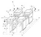
- FIG. 1is a diagrammatic perspective view of a portion of a substrate fragment comprising a ferroelectric field effect transistor construction in accordance with an embodiment of the invention.
- FIG. 2is a section view taken through line 2 - 2 in FIG. 1 .
- FIG. 3is a section view taken through line 3 - 3 in FIG. 1 .
- FIG. 4is a diagrammatic perspective view of a portion of a substrate fragment comprising an array of ferroelectric field effect transistor constructions in accordance with an embodiment of the invention.
- FIG. 5is a section view taken through line 5 - 5 in FIG. 4 .
- FIG. 6is a section view taken through line 6 - 6 in FIG. 4 .
- FIG. 7is a diagrammatic perspective view of a portion of a substrate fragment comprising an array of ferroelectric field effect transistor constructions in accordance with an embodiment of the invention.
- FIG. 8is a section view taken through line 8 - 8 in FIG. 7 .
- FIG. 9is a section view taken through line 9 - 9 in FIG. 7 .
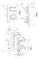
- FIG. 10is a diagrammatic section view of a portion of a substrate fragment comprising an array of ferroelectric field effect transistor constructions in accordance with an embodiment of the invention.
- FIG. 11is a diagrammatic perspective view of a portion of a substrate fragment in process in accordance with an embodiment of the invention.
- FIG. 12is a view of the FIG. 11 substrate at a processing step subsequent to that shown by FIG. 11 .
- FIG. 13is a section view taken through line 13 - 13 in FIG. 12 .
- FIG. 14is a section view taken through line 14 - 14 in FIG. 12 .
- FIG. 15is a view of the FIG. 12 substrate at a processing step subsequent to that shown by FIG. 12 .
- FIG. 16is a section view taken through line 16 - 16 in FIG. 15 .
- FIG. 17is a section view taken through line 17 - 17 in FIG. 15 .
- FIG. 18is a view of the FIG. 16 substrate at a processing step subsequent to that shown by FIG. 16 .
- FIG. 19is a view of the FIG. 17 substrate at a processing step subsequent to that shown by FIG. 17 , and corresponding in processing sequence to that of FIG. 18 .
- FIG. 20is a view of the FIG. 18 substrate at a processing step subsequent to that shown by FIG. 18 .
- FIG. 21is a view of the FIG. 19 substrate at a processing step subsequent to that shown by FIG. 19 , and corresponding in processing sequence to that of FIG. 20 .
- a ferroelectric field effect transistor 10 in accordance with an embodiment of the inventionis initially described with reference to FIGS. 1-3 .
- Example transistor 10is shown as having been fabricated relative to an underlying substrate 14 , which may include semiconductive material 12 of a semiconductor substrate.
- substrateor “semiconductive substrate” is defined to mean any construction comprising semiconductive material, including, but not limited to, bulk semiconductive materials such as a semiconductive wafer (either alone or in assemblies comprising other materials thereon), and semiconductive material layers (either alone or in assemblies comprising other materials).
- semiconductor-on-insulatorsemiconductor-on-insulator.
- substraterefers to any supporting structure, including, but not limited to, the semiconductive substrates described above.
- any of the materials and/or structures described hereinmay be homogenous or non-homogenous, and regardless may be continuous or discontinuous over any material that such overlie.
- “different composition”only requires those portions of two stated materials that may be directly against one another to be chemically and/or physically different, for example if such materials are not homogenous. If the two stated materials are not directly against one another, “different composition” only requires that those portions of the two stated materials that are closest to one another be chemically and/or physically different if such materials are not homogenous.
- a material or structureis “directly against” another when there is at least some physical touching contact of the stated materials or structures relative one another.
- each materialmay be formed using any suitable existing or yet-to-be-developed technique, with atomic layer deposition, chemical vapor deposition, physical vapor deposition, epitaxial growth, diffusion doping, and ion implanting being examples.
- Example material 12includes appropriately p-type and/or n-type doped monocrystalline or polycrystalline silicon.
- FIGS. 1-3depict transistor 10 in the absence of surrounding materials and circuitry for clarity. Other components of integrated circuitry may be elevationally outward, elevationally inward, and/or to the sides of transistor 10 . Additionally, multiple such transistors would likely constitute part of integrated circuitry, for example an array of such transistors that might be used in memory circuitry, logic circuitry, or other circuitry.
- Ferroelectric transistor 10comprises a semiconductive channel 14 ( FIGS. 2 and 3 ) that has opposing sidewalls 16 , 18 ( FIG. 2 ), opposite ends 17 ( FIG. 3 ), and an elevationally outermost top 20 ( FIGS. 2 and 3 ).
- a source/drain region 22( FIGS. 1 and 3 ) is at opposite ends 17 of channel 14 .
- Example ferroelectric transistor 10may be p-type or n-type, and lightly doped drain regions, halo regions, etc. (not shown) may be used. Regardless, transistor 10 is shown in part as having been fabricated relative to a rail or fin 25 that extends elevationally from a base 26 , each of which comprises semiconductive material 12 .
- An example elevational projecting distance of rail 25 relative to an elevationally outermost surface of base 26is about 200 to 2,000 Angstroms.
- An example maximum elevational thickness T SD for source/drain regions 22is about 100 to 1,000 Angstroms.
- FIGS. 1-3show source/drain regions 22 only being in elevationally outmost portions of rail 25 .
- the source/drain regionsmay project deeper into rails 25 , including completely elevationally there-into or there-through. Further, the source/drain regions may comprise elevated source/drain material.
- Ferroelectric transistor 10includes a gate construction 28 comprising various materials.
- Example gate construction 28includes inner dielectric 30 extending along channel top 20 and laterally along channel sidewalls 16 , 18 .
- Example inner dielectric materials 30include one or both of silicon dioxide and silicon nitride.
- An example thickness for dielectric 30is about 10 to 100 Angstroms.
- “thickness” by itselfis defined as the mean straight-line distance through a given material or region perpendicularly from a closest surface of an immediately adjacent material of different composition or of an immediately adjacent region.
- the various materials described hereinmay be of substantially constant thickness or of variable thicknesses.
- Inner conductive (i.e., electrically) material 32(designated in FIGS. 1 and 3 ) is elevationally and laterally outward of inner dielectric 30 and extends along channel top 20 and laterally along channel sidewalls 16 , 18 .
- Example inner conductive materials 32include any suitable one or more of elemental metals, alloys of two or more elemental metals, conductive metal compounds, and conductively doped semiconductive material.
- Example construction 28shows inner conductive material 32 as comprising materials 31 and 33 . In one example, each may be of the same chemical composition, for example TiN formed using two different deposition techniques as described below in connection with a method embodiment of the invention.
- Outer ferroelectric material 34is elevationally outward of inner conductive material 32 and extends along channel top 20 .
- Any suitable existing or yet-to-be-developed ferroelectric materialmay be used. Examples include ferroelectrics that have one or more of transition metal oxide, zirconium, zirconium oxide, hafnium, hafnium oxide, lead zirconium titanate, and barium strontium titanate, and may have dopant therein which comprises one or more of silicon, aluminum, lanthanum, yttrium, erbium, calcium, magnesium, strontium, and a rare earth element. Two specific examples are Hf x Si y O z and Hf x Zr y O z .
- An example thickness for outer ferroelectric material 34is about 10 to 100 Angstroms.
- Outer conductive material 36is elevationally outward of outer ferroelectric material 34 and extends along channel top 20 .
- Example materialsinclude any of those described above with respect to inner conductive material 32 , with one example being a composite of elemental tungsten and TiN. An example thickness for material 32 is about 100 to 1,000 Angstroms.
- Example gate construction 28may be considered by people of skill in the art as MFMIS construction.
- each source/drain region 22has a maximum elevational thickness T SD ( FIGS. 1 and 3 ) that is less than a maximum elevational thickness T ID of inner dielectric 30 ( FIG. 2 ). In one embodiment, each source/drain region 22 has a maximum elevational thickness T SD that is less than a maximum elevational thickness T ICM of inner conductive material 32 ( FIG. 2 ).
- inner conductive material 32has a maximum elevational thickness T ICM that is greater than a minimum width C MW of channel 14 taken orthogonally relative to a shortest straight-line distance C L (i.e., channel length) between source/drain regions 22 (e.g., C MW being shown in FIG. 2 and C L being shown in FIG. 3 ).
- C Lis shown as being greater than C MW , although this could be reversed or C L and C MW could be equal.
- inner conductive material 32has a maximum elevational thickness T ICM that is greater than channel length C L .
- inner conductive material 32 and inner dielectric 30have respective elevationally innermost surfaces 40 , 42 ( FIG. 2 ), respectively, that are not elevationally coincident.
- Field effect transistor 10is shown as being horizontally oriented, although vertical orientation or orientations other than vertical or horizontal may be used.
- verticalis a direction generally orthogonal to horizontal, with horizontal referring to a general direction along a primary surface relative to which a substrate is processed during fabrication.
- vertical and horizontal as used hereinare generally perpendicular directions relative one another independent of orientation of the substrate in three dimensional space. Additionally, elevational, above, and below are with reference to the vertical direction.
- a vertically oriented transistoris characterized by predominant current flow through the channel in the vertical direction.
- a horizontally oriented transistoris characterized by predominant current flow through the channel in the horizontal direction.
- each of outer conductive material 36 , outer ferroelectric material 34 , inner conductive material 32 , and inner dielectric 30 elevationally outward of channel 14are four-sided and shown as having vertical sidewalls (i.e., within 5° of vertical). Other than vertical and/or four-sided structuring may be used, for example more or less than four sides and/or with one or more sides being curved or having a combination of straight and curved segments.
- outer conductive material 36having four vertical sidewalls 45 - 48
- outer ferroelectric material 34having four vertical sidewalls 49 - 52
- inner conductive material 32having four vertical sidewalls 53 - 56
- inner dielectric 30having four vertical sidewalls 57 - 60 .
- all of the outer conductive material, the outer ferroelectric material, the inner conductive material, and the inner dielectrichave at least two laterally opposing vertical sidewalls elevationally outward of the channel that are laterally coincident relative one another.
- sidewalls 47 , 51 , 55 , and 59are laterally coincident relative one another
- sidewalls 48 , 52 , 56 , and 60are laterally coincident relative one another.
- all of the outer conductive material, the outer ferroelectric material, and the inner semiconductive materialhave at least two pairs of laterally opposing vertical sidewalls elevationally outward of the channel that are laterally coincident relative one another, for example as is shown with respect to gate construction 28 in FIGS. 1-3 .
- FIG. 1shows that all of the outer conductive material, the outer ferroelectric material, and the inner semiconductive material have at least two pairs of laterally opposing vertical sidewalls elevationally outward of the channel that are laterally coincident relative one another, for example as is shown with respect to gate construction 28 in FIGS. 1-3 .
- FIG. 3illustrates a pair of two laterally opposing vertical sidewalls 47 , 48 for outer conductive material 36 , a pair of two laterally opposing vertical sidewalls 51 , 52 for outer ferroelectric material 34 , a pair of two laterally opposing vertical sidewalls 55 , 56 for inner conductive material 32 , and wherein sidewalls 47 , 51 , 55 , and 59 are laterally coincident relative one another as are sidewalls 48 , 52 , 56 , and 60 .
- FIG. 2illustrates another pair of laterally opposing sidewalls 45 , 46 of outer conductive material 36 , another pair of laterally opposing vertical sidewalls 49 , 50 of outer ferroelectric material 34 , and another pair of two laterally opposing vertical sidewalls 53 , 54 of inner conductive material 32 , with sidewalls 45 , 49 , and 53 being laterally coincident relative one another and sidewalls 46 , 50 , and 54 being laterally coincident relative one another.
- Each of outer conductive material 36 , outer ferroelectric material 34 , and inner conductive material 32 in the depicted embodimentmay be considered as having respective encircling perimeter edges in at least one respective horizontal cross-section elevationally outward of channel 14 (e.g., respective perimeter edges as defined by their respective sidewalls in at least one horizontal plane).
- any two or all three of such encircling perimeter edgesare everywhere laterally coincident, with all three encircling perimeter being shown as being laterally coincident in example gate construction 28 in FIGS. 1-3 .
- Some embodiments of the inventioninclude a plurality of ferroelectric field effect transistors arrayed in row lines and column lines, for example an array 65 as shown in FIGS. 4-6 .
- Example array 65includes a plurality of ferroelectric field effect transistors 10 substantially as shown and described above with reference to FIGS. 1-3 .
- Transistors 10 in array 65are shown as extending in row lines 66 and column lines 67 .
- Use of “row” and “column” in this documentis for convenience in distinguishing one series of lines from another series of lines. Accordingly, “row” and “column” are intended to be synonymous with any series of lines independent of function.
- the rowsmay be straight and/or curved and/or parallel and/or not parallel relative one another, as may be the columns. Further, the rows and columns may intersect relative one another at 90° or at one or more other angles.
- each of the row lines and column linesare shown as being individually straight and angling relative one another at 90°.
- Dielectric isolating material(not shown) would likely be between and among lines 66 , 67 but is not shown for clarity. Only two row lines 66 and two column lines 67 are shown in FIGS. 4-6 , as are only two ferroelectric transistors 10 being shown in each line 66 and 67 .
- An arraywould likely have thousands or more transistors of like construction therein, arrayed in thousands or more column and row lines.
- At least one of the outer conductive material and the outer ferroelectric materialis discontinuous along both of the row lines and the column lines between immediately adjacent transistors.
- FIGS. 4-6depicts such an example, and additionally wherein both of outer conductive material 36 and outer ferroelectric material 34 are discontinuous along both of row lines 66 and column lines 67 between immediately adjacent transistors (i.e., within such respective lines).
- Conductive contactscan be made to the individual source/drain regions 22 , and individual conductive contacts (not shown) can be made to outer conductive material 36 of individual gate constructions 28 . Any other attribute(s) or construction(s) as described above may be used.
- the outer conductive material and the outer ferroelectric materialare discontinuous between immediately adjacent transistors along one of the collective row lines and the collective column lines.
- the conductive material and the outer ferroelectric materialare continuous between immediately adjacent transistors along the other of the collective row lines and the column lines.
- An alternate such exampleis shown in FIGS. 7-9 with respect to an array 65 a of a plurality of ferroelectric field effect transistors 10 .
- Like numerals from the above-described embodimentshave been used where appropriate, with some construction differences being indicated with the suffix “a” or with different numerals.
- Discontinuity of outer conductive material 36 and outer ferroelectric material 34is shown in array 65 a as being between immediately adjacent transistors 10 along column lines 67 .
- Outer conductive material 36 and outer ferroelectric material 34are continuous between immediately adjacent transistors along row lines 66 in the construction of FIGS. 7-9 .
- the relationshipcould be reversed (not shown) wherein such materials are continuous along the column lines and discontinuous along the row lines.
- a chosen array construction like 65 or 65 amight likely be dependent upon a particular circuitry architecture being fabricated (e.g., AND vs. NOR). Any other attribute(s) or construction(s) as described above may be used.
- the above array embodimentsshow a single source/drain region 22 being shared between and by two immediately adjacent transistors 10 in a given column 67 , and semiconductive material 12 also being continuous along an individual column 67 .
- the semiconductive material along individual columnsmay be formed to be partially or wholly discontinuous between immediately adjacent transistors, and/or source/drain regions 22 might not be shared by immediately adjacent transistors.
- One such example embodiment array 65 bis shown in FIG. 10 in comparison to the construction(s) as shown by FIGS. 6 and 9 .
- Like numerals from the above-described embodimentshave been used where appropriate, with some construction differences being indicated with different numerals or with the suffix “b” or with different numerals. In FIG.
- dielectric material 70e.g., silicon dioxide and/or silicon nitride
- Dielectric 70may be used to electrically isolate between adjacent components.
- Dielectric 70is shown extending through rails 25 and into base 26 . Alternately, the dielectric may extend only partially into rails 25 (not shown) or terminate at the interface of rails 25 and base 26 (not shown). Any other attribute(s) or construction(s) as described above may be used.
- Ferroelectric field effect transistors and arrays in accordance with the inventionmay be fabricated using any existing or yet-to-be-developed techniques, including for example those described below.
- Embodiments of the inventioninclude methods of forming a plurality of ferroelectric field effect transistors. Example such embodiments are described with reference to FIGS. 11-21 . Like numerals from the above-described embodiments have been used where appropriate, with some construction differences being indicated with different numerals or with the suffix “c”. Referring to FIG. 11 , a plurality of trenches 79 has been formed into semiconductive material 12 , thereby forming fins or rails 25 . Example trenches 79 are shown as being parallel and longitudinally elongated relative to horizontal.
- inner dielectric 30has been formed over sidewalls of trenches 79 and over semiconductive material 12 that is between trenches 79 .
- Inner dielectric 30may also be formed elevationally over the bases of trenches 79 as shown.
- First inner conductive material 31has been formed over inner dielectric 30 , the trench bases, the trench sidewalls, and semiconductive material 12 that is between trenches 79 .
- FIGS. 12-14depict an example embodiment wherein first inner conductive material 31 is formed to be both a) continuous between trenches 79 in a direction orthogonal to the horizontal longitudinal running direction of parallel trenches 79 , and b) continuous within trenches 79 .
- Example techniques for depositing first inner conductive materialinclude chemical vapor deposition and atomic layer deposition. Additionally, second inner conductive material 33 c has been formed over and is electrically coupled to first inner conductive material 31 . Second inner conductive material 33 c is formed to be elevationally thicker over the semiconductive material that is between the trenches than any that is formed elevationally centrally over the trench bases. In one embodiment and as shown, forming of second inner conductive material 33 c does form such material over the trench bases. In one such embodiment, second inner conductive material 33 is formed to run continuously over the trench bases, the trench sidewalls, and semiconductive material 12 between trenches 79 at least in the direction orthogonal to the longitudinal running direction of parallel trenches 79 .
- An example technique for depositing second inner conductive material 33 ce.g., TiN
- An example technique for depositing second inner conductive material 33 cincludes physical vapor deposition.
- etchinghas been conducted at least through second inner conductive material 33 c and first inner conductive material 31 to form lines 66 at least of first inner conductive material 31 and that run orthogonal to the longitudinal running direction of parallel trenches 79 .
- Dielectric 30may also be etched, for example completely there-through as shown.
- FIGS. 18 and 19such respectively correspond to section views 16 and 17 at a subsequent processing step.
- Anisotropic etchinghas been conducted of both a) first inner conductive material 31 from over the trench bases to isolate first inner conductive material 31 from being continuous over the individual trench bases, and b) second inner conductive material 33 c (designated as 33 post-etch) that is elevationally over semiconductive material 12 that is between trenches 79 .
- Such anisotropic etchingincludes at least one etching step which is common to the etching of both first inner conductive material 31 and second inner conductive material 33 c .
- the etchingleaves some of second inner conductive material 33 elevationally over first inner conductive material 31 between trenches 79 , and in one embodiment leaves some of second inner conductive material 33 laterally along the trench sidewalls.
- second inner conductive material 33 calso deposits centrally over the trench bases
- the common etching stepalso etches it from over the trench bases to isolate it from being continuous over the individual trench bases, as is shown.
- Source/drain regions 22may also be formed.
- etchingis shown as having occurred first with respect to FIGS. 15-17 and then with respect to FIGS. 18 and 19 . Alternately, this could be reversed whereby the FIGS. 18 and 19 etching occurs first (e.g., with respect to the FIGS. 12-14 construction) followed by the FIGS. 15-17 etching. Regardless, in one embodiment, the anisotropic etching exemplified by FIGS. 18 and 19 may be conducted in the absence of masking (i.e., in maskless/no mask manner) at least within an entirely of an array region of the transistors being formed.
- dielectric fill material 82e.g., silicon dioxide and/or silicon nitride
- dielectric fill material 82has been formed within trenches 79 over the trench bases and at least over first inner conductive material 31 that is along the trench sidewalls.
- Outer ferroelectric material 34has been formed elevationally over first inner conductive material 31 that is over semiconductive material 12 that is between trenches 79 .
- outer conductive material 36has been formed elevationally over outer ferroelectric material 34 .
- Outer conductive material 36 and outer ferroelectric material 34may then be patterned, by way of example, to produce either the array construction 65 of FIGS. 4-6 or the array construction 65 a of FIGS. 7-9 .
- a ferroelectric field effect transistorcomprises a semiconductive channel comprising opposing sidewalls and an elevationally outermost top.
- a source/drain regionis at opposite ends of the channel.
- a gate construction of the transistorcomprises inner dielectric extending along the channel top and laterally along the channel sidewalls.
- Inner conductive materialis elevationally and laterally outward of the inner dielectric and extends along the channel top and laterally along the channel sidewalls.
- Outer ferroelectric materialis elevationally outward of the inner conductive material and extends along the channel top.
- Outer conductive materialis elevationally outward of the outer ferroelectric material and extends along the channel.
- a plurality of ferroelectric field effect transistorsis arrayed in row lines and column lines.
- Individual of the ferroelectric field effect transistorscomprise a semiconductive channel comprising opposing sidewalls and an elevationally outermost top.
- a source/drain regionis at opposite ends of the channel.
- a gate construction of the individual transistorscomprises inner dielectric extending along the channel top and laterally along the channel sidewalls.
- Inner conductive materialis elevationally and laterally outward of the inner dielectric and extends along the channel top and laterally along the channel sidewalls.
- Outer ferroelectric materialis elevationally outward of the inner conductive material and extends along the channel top.
- Outer conductive materialis elevationally outward of the outer ferroelectric material and extends along the channel top. At least one of the outer conductive material and the outer ferroelectric material is discontinuous along both of the row lines and the column lines between immediately adjacent transistors.
- a plurality of ferroelectric field effect transistors arrayed in row lines and column linescomprises individual ferroelectric field effect transistors comprise a semiconductive channel comprising sidewalls and an elevationally outermost top.
- a source/drain regionis at opposite ends of the channel.
- a gate construction of the individual transistorscomprises inner dielectric extending along the channel top and laterally along the channel sidewalls.
- Inner conductive materialis elevationally and laterally outward of the inner dielectric and extends along the channel top and laterally along the channel sidewalls.
- Outer ferroelectric materialis elevationally outward of the inner conductive material and extends along the channel top.
- Outer conductive materialis elevationally outward of the outer ferroelectric material and extends along the channel top.
- the outer conductive material and the outer ferroelectric materialare discontinuous between immediately adjacent transistors along one of a) the collective row lines, and b) the collective column lines.
- the outer conductive material and the ferroelectric materialare continuous between immediately adjacent transistors along the other of the collective row lines and the collective column lines.
- an MFMIS transistorhas F along a horizontal channel surface and I along a vertical channel surface. In some such embodiments, F is not along any vertical channel surface of the transistor. In some such embodiments, I is along two vertical channel surfaces of the transistor. In some such embodiments, total area of I that is over the channel of the transistor is greater than total area of F that is over the channel of the transistor.
- a method of forming a plurality of ferroelectric field effect transistorscomprises forming a plurality of trenches into semiconductive material, the trenches being parallel and longitudinally elongated relative to horizontal.
- Inner dielectricis formed over sidewalls of the trenches and over semiconductive material that is between the trenches.
- First inner conductive materialis formed over the inner dielectric, bases of the trenches, the trench sidewalls, and the semiconductive material that is between the trenches.
- the first inner conductive materialis continuous within and between the trenches at least in a direction orthogonal to a horizontal longitudinal running direction of the parallel trenches.
- Second inner conductive materialis formed over and electrically couples to the first inner conductive material.
- the second inner conductive materialis formed elevationally thicker over the semiconductive material that is between the trenches than any that is formed elevationally centrally over the trench bases.
- anisotropically etchingis conducted of both: a) the first inner conductive material from over the trench bases to isolate the first inner conductive material from being continuous over the individual trench bases; and b) the second inner conductive material that is elevationally over the semiconductive material that is between the trenches.
- outer ferroelectric materialis formed elevationally over the first inner conductive material that is over the semiconductive material that is between the trenches.
- Outer conductive materialis formed elevationally over the outer ferroelectric material. Source/drain regions are formed in the semiconductive material that is between the trenches on opposing sides of the first inner conductive material that overlies the semiconductive material that is between the trenches.
Landscapes
- Semiconductor Memories (AREA)
- Non-Volatile Memory (AREA)
- Insulated Gate Type Field-Effect Transistor (AREA)
Abstract
Description
Claims (14)
Priority Applications (8)
| Application Number | Priority Date | Filing Date | Title |
|---|---|---|---|
| US14/260,977US9263577B2 (en) | 2014-04-24 | 2014-04-24 | Ferroelectric field effect transistors, pluralities of ferroelectric field effect transistors arrayed in row lines and column lines, and methods of forming a plurality of ferroelectric field effect transistors |
| CN201580021286.4ACN106463510B (en) | 2014-04-24 | 2015-04-15 | A plurality of ferroelectric field effect transistors forming an array and a method of forming the same |
| CN201911276025.3ACN111048522A (en) | 2014-04-24 | 2015-04-15 | A plurality of ferroelectric field effect transistors forming an array and a method of forming the same |
| PCT/US2015/025894WO2015164141A1 (en) | 2014-04-24 | 2015-04-15 | Ferroelectric field effect transistors, pluralities of ferroelectric field effect transistors arrayed in row lines and column lines, and methods of forming a plurality of ferroelectric field effect transistors |
| TW104113107ATWI619254B (en) | 2014-04-24 | 2015-04-23 | Ferroelectric field effect transistor, plurality of ferroelectric field effect transistors forming arrays by column line and row line method, and method for forming plurality of ferroelectric field effect transistors |
| US15/005,250US9761715B2 (en) | 2014-04-24 | 2016-01-25 | Ferroelectric field effect transistors, pluralities of ferroelectric field effect transistors arrayed in row lines and column lines, and methods of forming a plurality of ferroelectric field effect transistors |
| US15/677,252US10084084B2 (en) | 2014-04-24 | 2017-08-15 | Ferroelectric field effect transistors, pluralities of ferroelectric field effect transistors arrayed in row lines and column lines, and methods of forming a plurality of ferroelectric field effect transistors |
| US16/106,626US10727336B2 (en) | 2014-04-24 | 2018-08-21 | Ferroelectric field effect transistors, pluralities of ferroelectric field effect transistors arrayed in row lines and column lines, and methods of forming a plurality of ferroelectric field effect transistors |
Applications Claiming Priority (1)
| Application Number | Priority Date | Filing Date | Title |
|---|---|---|---|
| US14/260,977US9263577B2 (en) | 2014-04-24 | 2014-04-24 | Ferroelectric field effect transistors, pluralities of ferroelectric field effect transistors arrayed in row lines and column lines, and methods of forming a plurality of ferroelectric field effect transistors |
Related Child Applications (1)
| Application Number | Title | Priority Date | Filing Date |
|---|---|---|---|
| US15/005,250DivisionUS9761715B2 (en) | 2014-04-24 | 2016-01-25 | Ferroelectric field effect transistors, pluralities of ferroelectric field effect transistors arrayed in row lines and column lines, and methods of forming a plurality of ferroelectric field effect transistors |
Publications (2)
| Publication Number | Publication Date |
|---|---|
| US20150311349A1 US20150311349A1 (en) | 2015-10-29 |
| US9263577B2true US9263577B2 (en) | 2016-02-16 |
Family
ID=54333012
Family Applications (4)
| Application Number | Title | Priority Date | Filing Date |
|---|---|---|---|
| US14/260,977Active2034-04-26US9263577B2 (en) | 2014-04-24 | 2014-04-24 | Ferroelectric field effect transistors, pluralities of ferroelectric field effect transistors arrayed in row lines and column lines, and methods of forming a plurality of ferroelectric field effect transistors |
| US15/005,250ActiveUS9761715B2 (en) | 2014-04-24 | 2016-01-25 | Ferroelectric field effect transistors, pluralities of ferroelectric field effect transistors arrayed in row lines and column lines, and methods of forming a plurality of ferroelectric field effect transistors |
| US15/677,252ActiveUS10084084B2 (en) | 2014-04-24 | 2017-08-15 | Ferroelectric field effect transistors, pluralities of ferroelectric field effect transistors arrayed in row lines and column lines, and methods of forming a plurality of ferroelectric field effect transistors |
| US16/106,626ActiveUS10727336B2 (en) | 2014-04-24 | 2018-08-21 | Ferroelectric field effect transistors, pluralities of ferroelectric field effect transistors arrayed in row lines and column lines, and methods of forming a plurality of ferroelectric field effect transistors |
Family Applications After (3)
| Application Number | Title | Priority Date | Filing Date |
|---|---|---|---|
| US15/005,250ActiveUS9761715B2 (en) | 2014-04-24 | 2016-01-25 | Ferroelectric field effect transistors, pluralities of ferroelectric field effect transistors arrayed in row lines and column lines, and methods of forming a plurality of ferroelectric field effect transistors |
| US15/677,252ActiveUS10084084B2 (en) | 2014-04-24 | 2017-08-15 | Ferroelectric field effect transistors, pluralities of ferroelectric field effect transistors arrayed in row lines and column lines, and methods of forming a plurality of ferroelectric field effect transistors |
| US16/106,626ActiveUS10727336B2 (en) | 2014-04-24 | 2018-08-21 | Ferroelectric field effect transistors, pluralities of ferroelectric field effect transistors arrayed in row lines and column lines, and methods of forming a plurality of ferroelectric field effect transistors |
Country Status (4)
| Country | Link |
|---|---|
| US (4) | US9263577B2 (en) |
| CN (2) | CN106463510B (en) |
| TW (1) | TWI619254B (en) |
| WO (1) | WO2015164141A1 (en) |
Cited By (18)
| Publication number | Priority date | Publication date | Assignee | Title |
|---|---|---|---|---|
| US20180151745A1 (en)* | 2016-11-29 | 2018-05-31 | Taiwan Semiconductor Manufacturing Co., Ltd. | Semiconductor device and manufacturing method thereof |
| US10615288B1 (en) | 2018-10-24 | 2020-04-07 | International Business Machines Corporation | Integration scheme for non-volatile memory on gate-all-around structure |
| US10790304B2 (en) | 2018-07-26 | 2020-09-29 | Micron Technology, Inc. | Integrated assemblies comprising ferroelectric transistors and non-ferroelectric transistors |
| US10804274B2 (en) | 2019-02-27 | 2020-10-13 | International Business Machines Corporation | Co-integration of non-volatile memory on gate-all-around field effect transistor |
| DE102020100126B3 (en)* | 2020-01-03 | 2021-06-10 | Taiwan Semiconductor Manufacturing Co. Ltd. | Integrated circuit with at least one field effect transistor and a metal-ferroelectric-metal structure |
| US11631678B2 (en) | 2017-07-27 | 2023-04-18 | Micron Technology, Inc. | Memory arrays comprising memory cells |
| US11715797B2 (en) | 2019-08-27 | 2023-08-01 | Micron Technology, Inc. | Ferroelectric transistors and assemblies comprising ferroelectric transistors |
| USRE49715E1 (en) | 2017-05-08 | 2023-10-24 | Micron Technology, Inc. | Memory arrays |
| US11839086B2 (en) | 2021-07-16 | 2023-12-05 | Sunrise Memory Corporation | 3-dimensional memory string array of thin-film ferroelectric transistors |
| US11844204B2 (en) | 2019-12-19 | 2023-12-12 | Sunrise Memory Corporation | Process for preparing a channel region of a thin-film transistor in a 3-dimensional thin-film transistor array |
| US11864386B2 (en) | 2018-11-29 | 2024-01-02 | Micron Technology, Inc. | Memory arrays |
| US11915768B2 (en) | 2015-09-30 | 2024-02-27 | Sunrise Memory Corporation | Memory circuit, system and method for rapid retrieval of data sets |
| US11955156B2 (en) | 2016-04-20 | 2024-04-09 | Micron Technology, Inc. | Memory arrays, ferroelectric transistors, and methods of reading and writing relative to memory cells of memory arrays |
| US12073082B2 (en) | 2020-02-07 | 2024-08-27 | Sunrise Memory Corporation | High capacity memory circuit with low effective latency |
| US12183834B2 (en) | 2020-01-22 | 2024-12-31 | Sunrise Memory Corporation | Cool electron erasing in thin-film storage transistors |
| US12256547B2 (en) | 2020-01-22 | 2025-03-18 | Sunrise Memory Corporation | Silicon oxide nitride tunnel dielectric for a storage transistor in a 3-dimensional NOR memory string array |
| US12336182B2 (en) | 2021-03-08 | 2025-06-17 | Samsung Electronics Co., Ltd. | Semiconductor device having 3D stacked structure and method of manufacturing the same |
| US12402319B2 (en) | 2021-09-14 | 2025-08-26 | Sunrise Memory Corporation | Three-dimensional memory string array of thin-film ferroelectric transistors formed with an oxide semiconductor channel |
Families Citing this family (35)
| Publication number | Priority date | Publication date | Assignee | Title |
|---|---|---|---|---|
| US9337210B2 (en) | 2013-08-12 | 2016-05-10 | Micron Technology, Inc. | Vertical ferroelectric field effect transistor constructions, constructions comprising a pair of vertical ferroelectric field effect transistors, vertical strings of ferroelectric field effect transistors, and vertical strings of laterally opposing pairs of vertical ferroelectric field effect transistors |
| US9276134B2 (en) | 2014-01-10 | 2016-03-01 | Micron Technology, Inc. | Field effect transistor constructions and memory arrays |
| US9263577B2 (en) | 2014-04-24 | 2016-02-16 | Micron Technology, Inc. | Ferroelectric field effect transistors, pluralities of ferroelectric field effect transistors arrayed in row lines and column lines, and methods of forming a plurality of ferroelectric field effect transistors |
| US9472560B2 (en) | 2014-06-16 | 2016-10-18 | Micron Technology, Inc. | Memory cell and an array of memory cells |
| US9159829B1 (en) | 2014-10-07 | 2015-10-13 | Micron Technology, Inc. | Recessed transistors containing ferroelectric material |
| US9276092B1 (en) | 2014-10-16 | 2016-03-01 | Micron Technology, Inc. | Transistors and methods of forming transistors |
| US9305929B1 (en) | 2015-02-17 | 2016-04-05 | Micron Technology, Inc. | Memory cells |
| US9449972B1 (en)* | 2015-03-06 | 2016-09-20 | Globalfoundries Inc. | Ferroelectric FinFET |
| US10134982B2 (en) | 2015-07-24 | 2018-11-20 | Micron Technology, Inc. | Array of cross point memory cells |
| CN105702737B (en)* | 2016-02-05 | 2019-01-18 | 中国科学院微电子研究所 | Multi-gate FinFET connected with negative capacitor, manufacturing method thereof and electronic device |
| CN105633169A (en)* | 2016-03-04 | 2016-06-01 | 西安电子科技大学 | Ferro-electric field effect transistor based on InAs material and preparation method of ferro-electric field effect transistor |
| US9853150B1 (en)* | 2016-08-15 | 2017-12-26 | Taiwan Semiconductor Manufacturing Co., Ltd. | Method of fabricating epitaxial gate dielectrics and semiconductor device of the same |
| US10084057B2 (en)* | 2016-08-16 | 2018-09-25 | Globalfoundries Inc. | NVM device in SOI technology and method of fabricating an according device |
| CN107978527B (en)* | 2016-10-25 | 2020-08-28 | 中芯国际集成电路制造(上海)有限公司 | Semiconductor structure and manufacturing method thereof |
| US10396145B2 (en) | 2017-01-12 | 2019-08-27 | Micron Technology, Inc. | Memory cells comprising ferroelectric material and including current leakage paths having different total resistances |
| US10714400B2 (en) | 2017-08-30 | 2020-07-14 | Micron Technology, Inc. | Methods of forming semiconductor structures comprising thin film transistors including oxide semiconductors |
| US11289509B2 (en) | 2017-09-29 | 2022-03-29 | Intel Corporation | Double-gated ferroelectric field-effect transistor |
| CN108258048A (en)* | 2017-12-14 | 2018-07-06 | 中国科学院微电子研究所 | Tunneling field effect transistor and preparation method thereof |
| US10366983B2 (en) | 2017-12-29 | 2019-07-30 | Micron Technology, Inc. | Semiconductor devices including control logic structures, electronic systems, and related methods |
| US10297290B1 (en) | 2017-12-29 | 2019-05-21 | Micron Technology, Inc. | Semiconductor devices, and related control logic assemblies, control logic devices, electronic systems, and methods |
| US10340267B1 (en) | 2017-12-29 | 2019-07-02 | Micron Technology, Inc. | Semiconductor devices including control logic levels, and related memory devices, control logic assemblies, electronic systems, and methods |
| KR102404060B1 (en) | 2018-01-11 | 2022-06-02 | 삼성전자주식회사 | Seniconductor device including capacitor and method of forming the same |
| CN110245749B (en)* | 2018-03-08 | 2024-06-14 | 三星电子株式会社 | Computing unit, neural network and method for performing exclusive nor operation |
| JP2019179827A (en)* | 2018-03-30 | 2019-10-17 | ソニーセミコンダクタソリューションズ株式会社 | Semiconductor memory device and product-sum operation device |
| US10748931B2 (en) | 2018-05-08 | 2020-08-18 | Micron Technology, Inc. | Integrated assemblies having ferroelectric transistors with body regions coupled to carrier reservoirs |
| KR102739020B1 (en)* | 2018-07-06 | 2024-12-05 | 삼성전자주식회사 | Semiconductor device |
| US10629732B1 (en) | 2018-10-09 | 2020-04-21 | Micron Technology, Inc. | Elevationally-extending transistors, devices comprising elevationally-extending transistors, and methods of forming a device comprising elevationally-extending transistors |
| US11348932B2 (en) | 2019-03-06 | 2022-05-31 | Micron Technology, Inc. | Integrated assemblies having transistor body regions coupled to carrier-sink-structures; and methods of forming integrated assemblies |
| JP7173909B2 (en) | 2019-03-20 | 2022-11-16 | キオクシア株式会社 | semiconductor storage device |
| US11170834B2 (en) | 2019-07-10 | 2021-11-09 | Micron Technology, Inc. | Memory cells and methods of forming a capacitor including current leakage paths having different total resistances |
| US12166122B2 (en)* | 2020-12-23 | 2024-12-10 | Intel Corporation | Field-effect transistor (FET) with self-aligned ferroelectric capacitor and methods of fabrication |
| EP4203066A1 (en)* | 2021-12-21 | 2023-06-28 | IMEC vzw | Split gate ferrofet |
| US12396176B2 (en)* | 2022-01-24 | 2025-08-19 | Taiwan Semiconductor Manufacturing Company, Ltd. | 3T memory with enhanced speed of operation and data retention |
| US20230345733A1 (en)* | 2022-04-20 | 2023-10-26 | Taiwan Semiconductor Manufacturing Company, Ltd. | Fin structure for increasing performance of ferroelectric memory device |
| US20230387296A1 (en)* | 2022-05-29 | 2023-11-30 | Taiwan Semiconductor Manufacturing Company, Ltd. | Ferroelectric field effect transistor and methods of forming the same |
Citations (31)
| Publication number | Priority date | Publication date | Assignee | Title |
|---|---|---|---|---|
| US6370056B1 (en) | 2000-03-10 | 2002-04-09 | Symetrix Corporation | Ferroelectric memory and method of operating same |
| US20020125536A1 (en) | 1997-04-04 | 2002-09-12 | Nippon Steel Corporation | Semiconductor device and a method of manufacturing the same |
| US20030183936A1 (en) | 2002-03-28 | 2003-10-02 | Matsushita Electric Industrial Co., Ltd. | Semiconductor device and method for fabricating the same |
| US6674109B1 (en) | 1999-09-30 | 2004-01-06 | Rohm Co., Ltd. | Nonvolatile memory |
| US20040004240A1 (en) | 2002-07-08 | 2004-01-08 | Fujitsu Limited, | Semiconductor memory device having cylinder-type stacked capacitor and method for fabricating such a semiconductor memory device |
| US6717215B2 (en) | 2001-06-21 | 2004-04-06 | Hewlett-Packard Development Company, L.P. | Memory structures |
| US20050282296A1 (en) | 2004-06-21 | 2005-12-22 | Sharp Laboratories Of America Inc. | Asymmetrical programming ferroelectric memory transistor |
| US20060014307A1 (en) | 2003-06-30 | 2006-01-19 | Soon-Yong Kweon | Ferroelectric random access memory capacitor and method for manufacturing the same |
| US7180141B2 (en) | 2004-12-03 | 2007-02-20 | Texas Instruments Incorporated | Ferroelectric capacitor with parallel resistance for ferroelectric memory |
| WO2008073529A2 (en) | 2006-07-31 | 2008-06-19 | Drexel University | Integrated semiconductor and transition-metal oxide nanostructures and methods for preparing same |
| US20080225569A1 (en) | 2007-03-14 | 2008-09-18 | Seiko Epson Corporation | Ferroelectric capacitor and its manufacturing method |
| US7525830B2 (en) | 2004-04-23 | 2009-04-28 | Hynix Semiconductor Inc. | Nonvolatile ferroelectric perpendicular electrode cell, FeRAM having the cell and method for manufacturing the cell |
| JP2009170511A (en) | 2008-01-11 | 2009-07-30 | Toshiba Corp | Semiconductor element and semiconductor device |
| US20100110753A1 (en)* | 2008-10-31 | 2010-05-06 | Qimonda Ag | Ferroelectric Memory Cell Arrays and Method of Operating the Same |
| US20100140589A1 (en) | 2008-12-04 | 2010-06-10 | Ecole Polytechnique Federale De Lausanne (Epfl) | Ferroelectric tunnel fet switch and memory |
| US20100321975A1 (en) | 2008-02-28 | 2010-12-23 | Rohm Co., Ltd | Ferroelectric memory device |
| US20110033955A1 (en)* | 2006-02-17 | 2011-02-10 | Hee Bok Kang | Nonvolatile ferroelectric memory device and method for manufacturing the same |
| US8021897B2 (en) | 2009-02-19 | 2011-09-20 | Micron Technology, Inc. | Methods of fabricating a cross point memory array |
| US20110248324A1 (en) | 2006-01-27 | 2011-10-13 | Hynix Semiconductor Inc. | Dual-gate non-volatile ferroelectric memory |
| US20120248398A1 (en) | 2010-04-19 | 2012-10-04 | Micron Technology, Inc. | Vertical transistor phase change memory |
| US8304823B2 (en) | 2008-04-21 | 2012-11-06 | Namlab Ggmbh | Integrated circuit including a ferroelectric memory cell and method of manufacturing the same |
| US20120280291A1 (en) | 2011-05-04 | 2012-11-08 | Jae-Kyu Lee | Semiconductor device including gate openings |
| US20120319185A1 (en) | 2009-11-25 | 2012-12-20 | Institute of Microelectronics, Chinese Academy of Sciences | Nand structure and method of manufacturing the same |
| US20130043455A1 (en) | 2011-08-15 | 2013-02-21 | Unity Semiconductor Corporation | Vertical Cross Point Arrays For Ultra High Density Memory Applications |
| US20130056698A1 (en) | 2011-09-03 | 2013-03-07 | Kimihiro Satoh | Resistive memory device having vertical transistors and method for making the same |
| US20130126816A1 (en) | 2011-11-17 | 2013-05-23 | Micron Technology, Inc. | Memory Arrays and Methods of Forming Memory Cells |
| US20140153312A1 (en) | 2012-11-30 | 2014-06-05 | Micron Technology, Inc. | Memory cells having ferroelectric materials |
| US8796085B2 (en)* | 2012-10-12 | 2014-08-05 | Viktor Koldiaev | Vertical super-thin body semiconductor on dielectric wall devices and methods of their fabrication |
| WO2015023403A1 (en) | 2013-08-12 | 2015-02-19 | Micron Technology, Inc. | Vertical ferroelectric field effect transistor constructions, constructions comprising a pair of vertical ferroelectric field effect transistors, vertical strings of ferroelectric field effect transistors, and vertical strings of laterally opposing pairs of vertical ferroelectric field effect transistors |
| WO2015164141A1 (en) | 2014-04-24 | 2015-10-29 | Micron Technology, Inc. | Ferroelectric field effect transistors, pluralities of ferroelectric field effect transistors arrayed in row lines and column lines, and methods of forming a plurality of ferroelectric field effect transistors |
| WO2015195291A1 (en) | 2014-06-16 | 2015-12-23 | Micron Technology, Inc. | Memory cell and an array of memory cells |
Family Cites Families (152)
| Publication number | Priority date | Publication date | Assignee | Title |
|---|---|---|---|---|
| US4070653A (en) | 1976-06-29 | 1978-01-24 | Texas Instruments Incorporated | Random access memory cell with ion implanted resistor element |
| ATE223108T1 (en) | 1995-04-24 | 2002-09-15 | Infineon Technologies Ag | SEMICONDUCTOR STORAGE DEVICE USING A FERROELECTRIC DIELECTRIC AND METHOD FOR PRODUCING |
| JPH09213899A (en)* | 1996-02-06 | 1997-08-15 | Toshiba Corp | Nonvolatile memory device having ferroelectric film |
| JP2921468B2 (en) | 1996-02-19 | 1999-07-19 | 日本電気株式会社 | Semiconductor memory device |
| JPH1093083A (en) | 1996-09-18 | 1998-04-10 | Toshiba Corp | Method for manufacturing semiconductor device |
| US6336544B1 (en) | 1999-03-01 | 2002-01-08 | Casinovations Incorporated | Coin collection system |
| KR100269306B1 (en) | 1997-07-31 | 2000-10-16 | 윤종용 | Integrate circuit device having buffer layer containing metal oxide stabilized by low temperature treatment and fabricating method thereof |
| US6256220B1 (en) | 1997-09-15 | 2001-07-03 | Celis Semiconductor Corporation | Ferroelectric memory with shunted isolated nodes |
| JP3373403B2 (en) | 1997-09-16 | 2003-02-04 | 帝人株式会社 | Method for producing suede-like artificial leather |
| KR100292819B1 (en) | 1998-07-07 | 2001-09-17 | 윤종용 | Capacitor and manufacturing method thereof |
| US20030001189A1 (en) | 2000-02-24 | 2003-01-02 | Tetsuo Fujiwara | Ferroelectric capacitor and semiconductor device |
| US6249014B1 (en) | 1998-10-01 | 2001-06-19 | Ramtron International Corporation | Hydrogen barrier encapsulation techniques for the control of hydrogen induced degradation of ferroelectric capacitors in conjunction with multilevel metal processing for non-volatile integrated circuit memory devices |
| JP3743189B2 (en) | 1999-01-27 | 2006-02-08 | 富士通株式会社 | Nonvolatile semiconductor memory device and manufacturing method thereof |
| JP2000252372A (en)* | 1999-02-26 | 2000-09-14 | Sharp Corp | Semiconductor memory device and method of manufacturing the same |
| US6242299B1 (en) | 1999-04-01 | 2001-06-05 | Ramtron International Corporation | Barrier layer to protect a ferroelectric capacitor after contact has been made to the capacitor electrode |
| US6236076B1 (en)* | 1999-04-29 | 2001-05-22 | Symetrix Corporation | Ferroelectric field effect transistors for nonvolatile memory applications having functional gradient material |
| US6611014B1 (en) | 1999-05-14 | 2003-08-26 | Kabushiki Kaisha Toshiba | Semiconductor device having ferroelectric capacitor and hydrogen barrier film and manufacturing method thereof |
| US6635528B2 (en) | 1999-12-22 | 2003-10-21 | Texas Instruments Incorporated | Method of planarizing a conductive plug situated under a ferroelectric capacitor |
| US6417537B1 (en) | 2000-01-18 | 2002-07-09 | Micron Technology, Inc. | Metal oxynitride capacitor barrier layer |
| JP4938921B2 (en)* | 2000-03-16 | 2012-05-23 | 康夫 垂井 | Transistor-type ferroelectric nonvolatile memory element |
| US20020036313A1 (en) | 2000-06-06 | 2002-03-28 | Sam Yang | Memory cell capacitor structure and method of formation |
| US6339544B1 (en) | 2000-09-29 | 2002-01-15 | Intel Corporation | Method to enhance performance of thermal resistor device |
| US20020102808A1 (en) | 2001-01-31 | 2002-08-01 | Skyland Pu | Method for raising capacitance of a trench capacitor and reducing leakage current |
| US6448601B1 (en) | 2001-02-09 | 2002-09-10 | Micron Technology, Inc. | Memory address and decode circuits with ultra thin body transistors |
| US6566192B2 (en) | 2001-02-27 | 2003-05-20 | Nanya Technology Corporation | Method of fabricating a trench capacitor of a memory cell |
| US6717195B2 (en) | 2001-06-29 | 2004-04-06 | Rohm Co., Ltd. | Ferroelectric memory |
| JP2003045174A (en) | 2001-08-01 | 2003-02-14 | Sharp Corp | Semiconductor storage device |
| TW508808B (en) | 2001-09-14 | 2002-11-01 | Winbond Electronics Corp | Stacked type capacitor structure and its manufacturing method |
| US7075134B2 (en) | 2001-11-29 | 2006-07-11 | Symetrix Corporation | Ferroelectric and high dielectric constant integrated circuit capacitors with three-dimensional orientation for high-density memories, and method of making the same |
| KR100799129B1 (en) | 2001-12-24 | 2008-01-29 | 주식회사 하이닉스반도체 | Capacitor Manufacturing Method of Semiconductor Memory Device |
| AU2003221212A1 (en)* | 2002-03-26 | 2003-10-08 | Matsushita Electric Industrial Co., Ltd. | Semiconductor device and production method therefor |
| US6940085B2 (en) | 2002-04-02 | 2005-09-06 | Hewlett-Packard Development Company, I.P. | Memory structures |
| US6812509B2 (en) | 2002-06-28 | 2004-11-02 | Palo Alto Research Center Inc. | Organic ferroelectric memory cells |
| US7884349B2 (en) | 2002-08-02 | 2011-02-08 | Unity Semiconductor Corporation | Selection device for re-writable memory |
| US7186569B2 (en) | 2002-08-02 | 2007-03-06 | Unity Semiconductor Corporation | Conductive memory stack with sidewall |
| JP4509467B2 (en) | 2002-11-08 | 2010-07-21 | シャープ株式会社 | Nonvolatile variable resistance element and storage device |
| US6876021B2 (en) | 2002-11-25 | 2005-04-05 | Texas Instruments Incorporated | Use of amorphous aluminum oxide on a capacitor sidewall for use as a hydrogen barrier |
| JP4355136B2 (en) | 2002-12-05 | 2009-10-28 | シャープ株式会社 | Nonvolatile semiconductor memory device and reading method thereof |
| KR100493040B1 (en) | 2002-12-30 | 2005-06-07 | 삼성전자주식회사 | Capacitor of a semiconductor device and manufacturing method whereof |
| KR100480644B1 (en) | 2003-02-28 | 2005-03-31 | 삼성전자주식회사 | Phase-Change memory with increased cell driving current |
| JP4141861B2 (en) | 2003-03-03 | 2008-08-27 | 富士通株式会社 | Semiconductor device and manufacturing method thereof |
| US7755934B2 (en) | 2003-03-18 | 2010-07-13 | Kabushiki Kaisha Toshiba | Resistance change memory device |
| US6897472B2 (en) | 2003-06-26 | 2005-05-24 | Rj Mears, Llc | Semiconductor device including MOSFET having band-engineered superlattice |
| US7408212B1 (en) | 2003-07-18 | 2008-08-05 | Winbond Electronics Corporation | Stackable resistive cross-point memory with schottky diode isolation |
| US7067385B2 (en) | 2003-09-04 | 2006-06-27 | Micron Technology, Inc. | Support for vertically oriented capacitors during the formation of a semiconductor device |
| US7297602B2 (en)* | 2003-09-09 | 2007-11-20 | Sharp Laboratories Of America, Inc. | Conductive metal oxide gate ferroelectric memory transistor |
| US7001821B2 (en) | 2003-11-10 | 2006-02-21 | Texas Instruments Incorporated | Method of forming and using a hardmask for forming ferroelectric capacitors in a semiconductor device |
| US7816722B2 (en) | 2004-02-04 | 2010-10-19 | Hewlett-Packard Development Company, L.P. | Memory array |
| US7082052B2 (en) | 2004-02-06 | 2006-07-25 | Unity Semiconductor Corporation | Multi-resistive state element with reactive metal |
| JP4506951B2 (en)* | 2004-04-23 | 2010-07-21 | セイコーエプソン株式会社 | MFS type field effect transistor, ferroelectric memory, and semiconductor device |
| JP2006049566A (en) | 2004-08-04 | 2006-02-16 | Toshiba Corp | Semiconductor memory device and manufacturing method thereof |
| US7161213B2 (en) | 2004-08-05 | 2007-01-09 | Broadcom Corporation | Low threshold voltage PMOS apparatus and method of fabricating the same |
| KR100587396B1 (en) | 2004-08-13 | 2006-06-08 | 동부일렉트로닉스 주식회사 | Nonvolatile Memory Device and Manufacturing Method Thereof |
| US7378286B2 (en) | 2004-08-20 | 2008-05-27 | Sharp Laboratories Of America, Inc. | Semiconductive metal oxide thin film ferroelectric memory transistor |
| CN101124638A (en) | 2004-12-06 | 2008-02-13 | 哈佛大学 | Data storage based on nanoscale wires |
| JP4345676B2 (en) | 2005-01-12 | 2009-10-14 | エルピーダメモリ株式会社 | Semiconductor memory device |
| KR100707181B1 (en) | 2005-02-14 | 2007-04-13 | 삼성전자주식회사 | Semiconductor memory device having a dual storage node and its manufacturing and operation method |
| US8270193B2 (en) | 2010-01-29 | 2012-09-18 | Unity Semiconductor Corporation | Local bit lines and methods of selecting the same to access memory elements in cross-point arrays |
| KR100695513B1 (en) | 2005-06-15 | 2007-03-15 | 주식회사 하이닉스반도체 | Manufacturing method of semiconductor device |
| JP2007049016A (en) | 2005-08-11 | 2007-02-22 | Nec Electronics Corp | Semiconductor device and manufacturing method thereof |
| US7304339B2 (en) | 2005-09-22 | 2007-12-04 | Agile Rf, Inc. | Passivation structure for ferroelectric thin-film devices |
| JP2007157982A (en) | 2005-12-05 | 2007-06-21 | Seiko Epson Corp | Transistor type ferroelectric memory and manufacturing method thereof |
| JP4745108B2 (en) | 2006-04-06 | 2011-08-10 | 株式会社東芝 | Nonvolatile semiconductor memory device |
| US7558097B2 (en) | 2006-12-28 | 2009-07-07 | Intel Corporation | Memory having bit line with resistor(s) between memory cells |
| US8207063B2 (en) | 2007-01-26 | 2012-06-26 | Eastman Kodak Company | Process for atomic layer deposition |
| FR2913523B1 (en) | 2007-03-09 | 2009-06-05 | Commissariat Energie Atomique | MULTI-LEVEL DATA STORAGE DEVICE WITH PHASE CHANGE MATERIAL |
| WO2008126961A1 (en) | 2007-04-12 | 2008-10-23 | University Of Seoul Foundation Of Industry-Academic Cooperation | Mfmis-fet, mfmis-ferroelectric memory device, and methods of manufacturing the same |
| KR100876136B1 (en) | 2007-04-12 | 2008-12-29 | 서울시립대학교 산학협력단 | Field Effect Transistor and Ferroelectric Memory Device Having MFC Structure and Manufacturing Method Thereof |
| US7452776B1 (en)* | 2007-04-24 | 2008-11-18 | Promos Technoloies Pte. Ltd. | Integrated circuits with substrate protrusions, including (but not limited to) floating gate memories |
| JP2008277543A (en) | 2007-04-27 | 2008-11-13 | Toshiba Corp | Nonvolatile semiconductor memory device |
| US8487450B2 (en) | 2007-05-01 | 2013-07-16 | Micron Technology, Inc. | Semiconductor constructions comprising vertically-stacked memory units that include diodes utilizing at least two different dielectric materials, and electronic systems |
| US8294219B2 (en) | 2007-07-25 | 2012-10-23 | Intermolecular, Inc. | Nonvolatile memory element including resistive switching metal oxide layers |
| JP2009076653A (en) | 2007-09-20 | 2009-04-09 | Toshiba Corp | Semiconductor device and manufacturing method thereof |
| US7892956B2 (en) | 2007-09-24 | 2011-02-22 | International Business Machines Corporation | Methods of manufacture of vertical nanowire FET devices |
| KR101226685B1 (en) | 2007-11-08 | 2013-01-25 | 삼성전자주식회사 | Vertical type semiconductor device and Method of manufacturing the same |
| KR20090055874A (en) | 2007-11-29 | 2009-06-03 | 삼성전자주식회사 | Nonvolatile Memory Device and Manufacturing Method Thereof |
| TWI360708B (en) | 2007-12-17 | 2012-03-21 | Au Optronics Corp | Pixel structure, display panel, elecro-optical app |
| US8394683B2 (en) | 2008-01-15 | 2013-03-12 | Micron Technology, Inc. | Methods of forming semiconductor constructions, and methods of forming NAND unit cells |
| US8034655B2 (en) | 2008-04-08 | 2011-10-11 | Micron Technology, Inc. | Non-volatile resistive oxide memory cells, non-volatile resistive oxide memory arrays, and methods of forming non-volatile resistive oxide memory cells and memory arrays |
| JP5288877B2 (en) | 2008-05-09 | 2013-09-11 | 株式会社東芝 | Nonvolatile semiconductor memory device |
| JP5546740B2 (en) | 2008-05-23 | 2014-07-09 | ローム株式会社 | Semiconductor device |
| US8004871B2 (en) | 2008-05-26 | 2011-08-23 | Panasonic Corporation | Semiconductor memory device including FET memory elements |
| JP2010044844A (en) | 2008-08-18 | 2010-02-25 | Toshiba Corp | Semiconductor storage device |
| US7791925B2 (en) | 2008-10-31 | 2010-09-07 | Seagate Technology, Llc | Structures for resistive random access memory cells |
| US8773881B2 (en) | 2009-03-10 | 2014-07-08 | Contour Semiconductor, Inc. | Vertical switch three-dimensional memory array |
| US8193522B2 (en) | 2009-04-09 | 2012-06-05 | Qualcomm Incorporated | Diamond type quad-resistor cells of PRAM |
| US8173987B2 (en) | 2009-04-27 | 2012-05-08 | Macronix International Co., Ltd. | Integrated circuit 3D phase change memory array and manufacturing method |
| US7968876B2 (en) | 2009-05-22 | 2011-06-28 | Macronix International Co., Ltd. | Phase change memory cell having vertical channel access transistor |
| JP5025696B2 (en) | 2009-08-11 | 2012-09-12 | 株式会社東芝 | Resistance change memory |
| JP2013510438A (en) | 2009-11-06 | 2013-03-21 | ラムバス・インコーポレーテッド | Three-dimensional memory array stack structure |
| US8441097B2 (en) | 2009-12-23 | 2013-05-14 | Intel Corporation | Methods to form memory devices having a capacitor with a recessed electrode |
| KR101780841B1 (en) | 2010-02-26 | 2017-09-21 | 가부시키가이샤 한도오따이 에네루기 켄큐쇼 | Semiconductor device |
| US8411477B2 (en) | 2010-04-22 | 2013-04-02 | Micron Technology, Inc. | Arrays of vertically stacked tiers of non-volatile cross point memory cells, methods of forming arrays of vertically stacked tiers of non-volatile cross point memory cells, and methods of reading a data value stored by an array of vertically stacked tiers of non-volatile cross point memory cells |
| US8570785B2 (en) | 2010-05-26 | 2013-10-29 | Hewlett-Packard Development Company | Reading a memory element within a crossbar array |
| CN102263122B (en) | 2010-05-28 | 2012-12-12 | 旺宏电子股份有限公司 | non-volatile storage device |
| US8241944B2 (en) | 2010-07-02 | 2012-08-14 | Micron Technology, Inc. | Resistive RAM devices and methods |
| US8890233B2 (en) | 2010-07-06 | 2014-11-18 | Macronix International Co., Ltd. | 3D memory array with improved SSL and BL contact layout |
| US8207032B2 (en) | 2010-08-31 | 2012-06-26 | Micron Technology, Inc. | Methods of forming pluralities of vertical transistors, and methods of forming memory arrays |
| US8659944B2 (en) | 2010-09-01 | 2014-02-25 | Macronix International Co., Ltd. | Memory architecture of 3D array with diode in memory string |
| US8796661B2 (en) | 2010-11-01 | 2014-08-05 | Micron Technology, Inc. | Nonvolatile memory cells and methods of forming nonvolatile memory cell |
| US9454997B2 (en) | 2010-12-02 | 2016-09-27 | Micron Technology, Inc. | Array of nonvolatile memory cells having at least five memory cells per unit cell, having a plurality of the unit cells which individually comprise three elevational regions of programmable material, and/or having a continuous volume having a combination of a plurality of vertically oriented memory cells and a plurality of horizontally oriented memory cells; array of vertically stacked tiers of nonvolatile memory cells |
| US8431458B2 (en) | 2010-12-27 | 2013-04-30 | Micron Technology, Inc. | Methods of forming a nonvolatile memory cell and methods of forming an array of nonvolatile memory cells |
| US8399874B2 (en) | 2011-01-17 | 2013-03-19 | Snu R&Db Foundation | Vertical nonvolatile memory device including a selective diode |
| US8791447B2 (en) | 2011-01-20 | 2014-07-29 | Micron Technology, Inc. | Arrays of nonvolatile memory cells and methods of forming arrays of nonvolatile memory cells |
| US8462537B2 (en) | 2011-03-21 | 2013-06-11 | Intel Corporation | Method and apparatus to reset a phase change memory and switch (PCMS) memory cell |
| JP5662237B2 (en) | 2011-05-10 | 2015-01-28 | 株式会社日立製作所 | Semiconductor memory device |
| US8847196B2 (en) | 2011-05-17 | 2014-09-30 | Micron Technology, Inc. | Resistive memory cell |
| US20120327714A1 (en) | 2011-06-23 | 2012-12-27 | Macronix International Co., Ltd. | Memory Architecture of 3D Array With Diode in Memory String |
| KR20130005878A (en) | 2011-07-07 | 2013-01-16 | 삼성전자주식회사 | Low-resistance semiconductor device |
| US8946812B2 (en) | 2011-07-21 | 2015-02-03 | Semiconductor Energy Laboratory Co., Ltd. | Semiconductor device and manufacturing method thereof |
| US8536561B2 (en) | 2011-10-17 | 2013-09-17 | Micron Technology, Inc. | Memory cells and memory cell arrays |
| US8760909B2 (en) | 2011-10-20 | 2014-06-24 | Macronix International Co., Ltd. | Memory and manufacturing method thereof |
| US20130193400A1 (en) | 2012-01-27 | 2013-08-01 | Micron Technology, Inc. | Memory Cell Structures and Memory Arrays |
| KR20130092925A (en) | 2012-02-13 | 2013-08-21 | 에스케이하이닉스 주식회사 | Variable resistive memory device and method of fabricating the same |
| US9368581B2 (en) | 2012-02-20 | 2016-06-14 | Micron Technology, Inc. | Integrated circuitry components, switches, and memory cells |
| US9041129B2 (en) | 2012-02-24 | 2015-05-26 | National Applied Research Laboratories | Semiconductor memory storage array device and method for fabricating the same |
| US9152428B2 (en)* | 2012-09-28 | 2015-10-06 | Intel Corporation | Alternative boot path support for utilizing non-volatile memory devices |
| KR102031187B1 (en) | 2012-10-05 | 2019-10-14 | 삼성전자주식회사 | Vertical type memory device |
| US8796751B2 (en) | 2012-11-20 | 2014-08-05 | Micron Technology, Inc. | Transistors, memory cells and semiconductor constructions |
| US8878271B2 (en) | 2013-03-01 | 2014-11-04 | Micron Technology, Inc. | Vertical access device and apparatuses having a body connection line, and related method of operating the same |
| JP5793525B2 (en)* | 2013-03-08 | 2015-10-14 | 株式会社東芝 | Nonvolatile semiconductor memory device |
| US20140252298A1 (en) | 2013-03-10 | 2014-09-11 | Sandisk 3D Llc | Methods and apparatus for metal oxide reversible resistance-switching memory devices |
| US8969170B2 (en) | 2013-03-14 | 2015-03-03 | Globalfoundries Inc. | Method of forming a semiconductor structure including a metal-insulator-metal capacitor |
| US9196831B2 (en) | 2013-03-14 | 2015-11-24 | Crossbar, Inc. | Two-terminal memory with intrinsic rectifying characteristic |
| US20140269046A1 (en) | 2013-03-15 | 2014-09-18 | Micron Technology, Inc. | Apparatuses and methods for use in selecting or isolating memory cells |
| US9691981B2 (en) | 2013-05-22 | 2017-06-27 | Micron Technology, Inc. | Memory cell structures |
| US9153777B2 (en) | 2013-06-03 | 2015-10-06 | Micron Technology, Inc. | Thermally optimized phase change memory cells and methods of fabricating the same |
| JP6121819B2 (en) | 2013-07-04 | 2017-04-26 | 株式会社東芝 | Semiconductor device and dielectric film |
| US9246100B2 (en) | 2013-07-24 | 2016-01-26 | Micron Technology, Inc. | Memory cell array structures and methods of forming the same |
| US20150028280A1 (en) | 2013-07-26 | 2015-01-29 | Micron Technology, Inc. | Memory cell with independently-sized elements |
| JP6067524B2 (en) | 2013-09-25 | 2017-01-25 | 株式会社東芝 | Semiconductor device and dielectric film |
| KR20150041705A (en) | 2013-10-08 | 2015-04-17 | 삼성전자주식회사 | Semiconductor device having selector and resistive change device and method of forming the same |
| US9543515B2 (en) | 2013-11-07 | 2017-01-10 | Intel Corporation | Electrode materials and interface layers to minimize chalcogenide interface resistance |
| KR102131075B1 (en) | 2013-11-12 | 2020-07-07 | 삼성전자주식회사 | A semiconductor device and method for manufacturing the same |
| US9276134B2 (en) | 2014-01-10 | 2016-03-01 | Micron Technology, Inc. | Field effect transistor constructions and memory arrays |
| US9806129B2 (en) | 2014-02-25 | 2017-10-31 | Micron Technology, Inc. | Cross-point memory and methods for fabrication of same |
| US20150249113A1 (en) | 2014-02-28 | 2015-09-03 | Kabushiki Kaisha Toshiba | Nonvolatile memory device |
| US9601194B2 (en) | 2014-02-28 | 2017-03-21 | Crossbar, Inc. | NAND array comprising parallel transistor and two-terminal switching device |
| US9922709B2 (en) | 2014-05-20 | 2018-03-20 | Sandisk Technologies Llc | Memory hole bit line structures |
| KR20150135804A (en) | 2014-05-26 | 2015-12-04 | 삼성전자주식회사 | Variable resistance memory devices and methods of manufacturing the same |
| US9362494B2 (en) | 2014-06-02 | 2016-06-07 | Micron Technology, Inc. | Array of cross point memory cells and methods of forming an array of cross point memory cells |
| US9343506B2 (en) | 2014-06-04 | 2016-05-17 | Micron Technology, Inc. | Memory arrays with polygonal memory cells having specific sidewall orientations |
| US9437658B2 (en) | 2014-08-05 | 2016-09-06 | Sandisk Technologies Llc | Fully isolated selector for memory device |
| US9159829B1 (en) | 2014-10-07 | 2015-10-13 | Micron Technology, Inc. | Recessed transistors containing ferroelectric material |
| US9276092B1 (en) | 2014-10-16 | 2016-03-01 | Micron Technology, Inc. | Transistors and methods of forming transistors |
| US9305929B1 (en) | 2015-02-17 | 2016-04-05 | Micron Technology, Inc. | Memory cells |
| CN104908800A (en) | 2015-05-27 | 2015-09-16 | 张君贝 | Steering wheel protective cover |
| KR102450814B1 (en) | 2015-12-29 | 2022-10-05 | 에스케이하이닉스 주식회사 | Threshold switching device, method for fabricating the same and electronic device including the same |
| US10163917B2 (en) | 2016-11-01 | 2018-12-25 | Micron Technology, Inc. | Cell disturb prevention using a leaker device to reduce excess charge from an electronic device |
| US10396145B2 (en) | 2017-01-12 | 2019-08-27 | Micron Technology, Inc. | Memory cells comprising ferroelectric material and including current leakage paths having different total resistances |
| KR20180105530A (en) | 2017-03-15 | 2018-09-28 | 에스케이하이닉스 주식회사 | Ferroelectric Memory Device and Cross Point Array Apparatus using the same |
| US10650978B2 (en) | 2017-12-15 | 2020-05-12 | Micron Technology, Inc. | Methods of incorporating leaker devices into capacitor configurations to reduce cell disturb |
- 2014
- 2014-04-24USUS14/260,977patent/US9263577B2/enactiveActive
- 2015
- 2015-04-15WOPCT/US2015/025894patent/WO2015164141A1/enactiveApplication Filing
- 2015-04-15CNCN201580021286.4Apatent/CN106463510B/enactiveActive
- 2015-04-15CNCN201911276025.3Apatent/CN111048522A/ennot_activeWithdrawn
- 2015-04-23TWTW104113107Apatent/TWI619254B/enactive
- 2016
- 2016-01-25USUS15/005,250patent/US9761715B2/enactiveActive
- 2017
- 2017-08-15USUS15/677,252patent/US10084084B2/enactiveActive
- 2018
- 2018-08-21USUS16/106,626patent/US10727336B2/enactiveActive
Patent Citations (32)
| Publication number | Priority date | Publication date | Assignee | Title |
|---|---|---|---|---|
| US20020125536A1 (en) | 1997-04-04 | 2002-09-12 | Nippon Steel Corporation | Semiconductor device and a method of manufacturing the same |
| US6674109B1 (en) | 1999-09-30 | 2004-01-06 | Rohm Co., Ltd. | Nonvolatile memory |
| US6370056B1 (en) | 2000-03-10 | 2002-04-09 | Symetrix Corporation | Ferroelectric memory and method of operating same |
| US6717215B2 (en) | 2001-06-21 | 2004-04-06 | Hewlett-Packard Development Company, L.P. | Memory structures |
| US20030183936A1 (en) | 2002-03-28 | 2003-10-02 | Matsushita Electric Industrial Co., Ltd. | Semiconductor device and method for fabricating the same |
| US20040004240A1 (en) | 2002-07-08 | 2004-01-08 | Fujitsu Limited, | Semiconductor memory device having cylinder-type stacked capacitor and method for fabricating such a semiconductor memory device |
| US20060014307A1 (en) | 2003-06-30 | 2006-01-19 | Soon-Yong Kweon | Ferroelectric random access memory capacitor and method for manufacturing the same |
| US7525830B2 (en) | 2004-04-23 | 2009-04-28 | Hynix Semiconductor Inc. | Nonvolatile ferroelectric perpendicular electrode cell, FeRAM having the cell and method for manufacturing the cell |
| US20050282296A1 (en) | 2004-06-21 | 2005-12-22 | Sharp Laboratories Of America Inc. | Asymmetrical programming ferroelectric memory transistor |
| US7180141B2 (en) | 2004-12-03 | 2007-02-20 | Texas Instruments Incorporated | Ferroelectric capacitor with parallel resistance for ferroelectric memory |
| US20110248324A1 (en) | 2006-01-27 | 2011-10-13 | Hynix Semiconductor Inc. | Dual-gate non-volatile ferroelectric memory |
| US20110033955A1 (en)* | 2006-02-17 | 2011-02-10 | Hee Bok Kang | Nonvolatile ferroelectric memory device and method for manufacturing the same |
| WO2008073529A2 (en) | 2006-07-31 | 2008-06-19 | Drexel University | Integrated semiconductor and transition-metal oxide nanostructures and methods for preparing same |
| US20080225569A1 (en) | 2007-03-14 | 2008-09-18 | Seiko Epson Corporation | Ferroelectric capacitor and its manufacturing method |
| US7902594B2 (en) | 2008-01-11 | 2011-03-08 | Kabushiki Kaisha Toshiba | Semiconductor component and semiconductor device |
| JP2009170511A (en) | 2008-01-11 | 2009-07-30 | Toshiba Corp | Semiconductor element and semiconductor device |
| US20100321975A1 (en) | 2008-02-28 | 2010-12-23 | Rohm Co., Ltd | Ferroelectric memory device |
| US8304823B2 (en) | 2008-04-21 | 2012-11-06 | Namlab Ggmbh | Integrated circuit including a ferroelectric memory cell and method of manufacturing the same |
| US20100110753A1 (en)* | 2008-10-31 | 2010-05-06 | Qimonda Ag | Ferroelectric Memory Cell Arrays and Method of Operating the Same |
| US20100140589A1 (en) | 2008-12-04 | 2010-06-10 | Ecole Polytechnique Federale De Lausanne (Epfl) | Ferroelectric tunnel fet switch and memory |
| US8021897B2 (en) | 2009-02-19 | 2011-09-20 | Micron Technology, Inc. | Methods of fabricating a cross point memory array |
| US20120319185A1 (en) | 2009-11-25 | 2012-12-20 | Institute of Microelectronics, Chinese Academy of Sciences | Nand structure and method of manufacturing the same |
| US20120248398A1 (en) | 2010-04-19 | 2012-10-04 | Micron Technology, Inc. | Vertical transistor phase change memory |
| US20120280291A1 (en) | 2011-05-04 | 2012-11-08 | Jae-Kyu Lee | Semiconductor device including gate openings |
| US20130043455A1 (en) | 2011-08-15 | 2013-02-21 | Unity Semiconductor Corporation | Vertical Cross Point Arrays For Ultra High Density Memory Applications |
| US20130056698A1 (en) | 2011-09-03 | 2013-03-07 | Kimihiro Satoh | Resistive memory device having vertical transistors and method for making the same |
| US20130126816A1 (en) | 2011-11-17 | 2013-05-23 | Micron Technology, Inc. | Memory Arrays and Methods of Forming Memory Cells |
| US8796085B2 (en)* | 2012-10-12 | 2014-08-05 | Viktor Koldiaev | Vertical super-thin body semiconductor on dielectric wall devices and methods of their fabrication |
| US20140153312A1 (en) | 2012-11-30 | 2014-06-05 | Micron Technology, Inc. | Memory cells having ferroelectric materials |
| WO2015023403A1 (en) | 2013-08-12 | 2015-02-19 | Micron Technology, Inc. | Vertical ferroelectric field effect transistor constructions, constructions comprising a pair of vertical ferroelectric field effect transistors, vertical strings of ferroelectric field effect transistors, and vertical strings of laterally opposing pairs of vertical ferroelectric field effect transistors |
| WO2015164141A1 (en) | 2014-04-24 | 2015-10-29 | Micron Technology, Inc. | Ferroelectric field effect transistors, pluralities of ferroelectric field effect transistors arrayed in row lines and column lines, and methods of forming a plurality of ferroelectric field effect transistors |
| WO2015195291A1 (en) | 2014-06-16 | 2015-12-23 | Micron Technology, Inc. | Memory cell and an array of memory cells |
Non-Patent Citations (22)
| Title |
|---|
| Breakdown of High-Performance Monolayer MoS2 Transistors; Lembke et al.; www.acsnano.org; Oct. 2012; pp, A-F. |
| Current Status of Ferroelectric Random-Acess Memory; Arimoto et al.; MRS Bulletin; Nov. 2004; pp. 823-828 |
| Das et al.; High Performance Multliayer MoS2 Transistors with Scandium Contacts; NANO Letters; ACS Publications; Dec. 14, 2012; pp. 100-105. |
| Ferroelectric Nonvolatile Nanowire Memory Circuit Using a Single ZnO Nanowire and Copolymer Top Layer; Tack Lee et al.; Advanced Materials 2012, 24, pp. 3020-3025. |
| Ferroelectric RAM; http://en.wikipedia.org/wiki/Ferroelectric-RAM; Last Modified Feb. 25, 2013; 6 pp. |
| Large Area Vapor Phase Growth and Characterization of MoS2 Atomic Layers on SiO2 Substrate; Zhan et al.; Dept. of Mechanical Engineering & Materials Science; Rice University: Feb. 15, 2012; 24 pp. |
| Liu et al.; Growth of Large-Area and Highly Crystailine MoS2 Thin Layers on Insulating Substrates; NANO Letters; ACS Publications; Feb. 27, 2012; pp. 1538-1544. |
| Min et al.; Nanosheet thickness-modulated MoS2 dielectric property evidenced by field-effect transistor performance; The Royal Society of Chemistry; Dec. 3, 2012; 2 pp. |
| MoS 2 Nanosheets for Top-Gate Nonvolatile Memory Transistor Channel; Sung Lee et al.; Small 2012,8, No. 20, pp. 3111-3115. |
| Nonvolatile ferroelectric-gate field-effect transistors using SrBi2Ta2O9/Pt/SRTa2O6/SiON/Si structures; E. Tokumitsu; Applied Physics Letters, vol. 75, No. 4; Jul. 26, 1999; pp. 575-577. |
| Pandey et al., "Structural, ferroelectric and optical properties of PZT thin films", 2005, Physica B, vol. 368, Nov. 2005; pp. 135-142. |
| R.S. Lous; Ferroelectric Memory Devices, How to store information of the future; Top Master Programme in Nanoscience; Jul. 2011; 23 pp. |
| Recent Progress of Ferroelectric-Gate Field-Effect Transistors and Applications to Nonvolatile Logic and FeNAND Flash Memory; Sakai et al.; Materials 2010, 3, Nov. 18, 2010; pp. 4950-4964. |
| Robertson, "Band offsets of wide-band-gap oxides and implications for future electronic devices"; J. Vac. Sci. Technol., B 18(3); May 2000; pp. 1785-1791. |
| Single-layer MoS2 transistors; Radisavijevic et al.; Nature Nanotechnology; vol. 6; Mar. 2011; pp. 147-150. |
| U.S. Appl. No. 13/964,309, filed Aug. 12, 2013, Karda et al. |
| U.S. Appl. No. 14/152,664, filed Jan. 10, 2014, Karda et al. |
| U.S. Appl. No. 14/152,664, filed Jan. 10, 2014, Karda. |
| U.S. Appl. No. 14/305,459, filed Jun. 16, 2014, Ramaswamy et al. |
| U.S. Appl. No. 14/508,912, Oct. 7, 2014, Ramaswamy. |
| W. Liu et al.; Role of Metal Contacts in Designing High-Performance Monolayer n-Type WSe2 Field Effect Transistors; NANO Letters; ACS Publications; Mar. 25, 2013; pp. 1983-1990. |
| Zhang et al.; Ambipolar MoS2 thin Flake Transistors; NANO Letters; ACS Publications; Jan. 25, 2012; pp. 1136-1140. |
Cited By (31)
| Publication number | Priority date | Publication date | Assignee | Title |
|---|---|---|---|---|
| US12002523B2 (en) | 2015-09-30 | 2024-06-04 | Sunrise Memory Corporation | Memory circuit, system and method for rapid retrieval of data sets |
| US11915768B2 (en) | 2015-09-30 | 2024-02-27 | Sunrise Memory Corporation | Memory circuit, system and method for rapid retrieval of data sets |
| US12223994B2 (en) | 2016-04-20 | 2025-02-11 | Micron Technology, Inc. | Memory arrays, ferroelectric transistors, and methods of reading and writing relative to memory cells of memory arrays |
| US11955156B2 (en) | 2016-04-20 | 2024-04-09 | Micron Technology, Inc. | Memory arrays, ferroelectric transistors, and methods of reading and writing relative to memory cells of memory arrays |
| TWI667790B (en)* | 2016-11-29 | 2019-08-01 | 台灣積體電路製造股份有限公司 | Semiconductor device and manufacturing method thereof |
| US11728332B2 (en) | 2016-11-29 | 2023-08-15 | Taiwan Semiconductor Manufacturing Company, Ltd. | Semiconductor device and manufacturing method thereof |
| US10937783B2 (en)* | 2016-11-29 | 2021-03-02 | Taiwan Semiconductor Manufacturing Co., Ltd. | Semiconductor device and manufacturing method thereof |
| US20180151745A1 (en)* | 2016-11-29 | 2018-05-31 | Taiwan Semiconductor Manufacturing Co., Ltd. | Semiconductor device and manufacturing method thereof |
| US11043489B2 (en) | 2016-11-29 | 2021-06-22 | Taiwan Semiconductor Manufacturing Co., Ltd. | Semiconductor device and manufacturing method thereof |
| USRE49715E1 (en) | 2017-05-08 | 2023-10-24 | Micron Technology, Inc. | Memory arrays |
| US11631678B2 (en) | 2017-07-27 | 2023-04-18 | Micron Technology, Inc. | Memory arrays comprising memory cells |
| US11515331B2 (en) | 2018-07-26 | 2022-11-29 | Micron Technology, Inc. | Integrated assemblies comprising ferroelectric transistors and non-ferroelectric transistors |
| US10790304B2 (en) | 2018-07-26 | 2020-09-29 | Micron Technology, Inc. | Integrated assemblies comprising ferroelectric transistors and non-ferroelectric transistors |
| US10749040B2 (en) | 2018-10-24 | 2020-08-18 | International Business Machines Corporation | Integration scheme for non-volatile memory on gate-all-around structure |
| US10615288B1 (en) | 2018-10-24 | 2020-04-07 | International Business Machines Corporation | Integration scheme for non-volatile memory on gate-all-around structure |
| US11864386B2 (en) | 2018-11-29 | 2024-01-02 | Micron Technology, Inc. | Memory arrays |
| US10804274B2 (en) | 2019-02-27 | 2020-10-13 | International Business Machines Corporation | Co-integration of non-volatile memory on gate-all-around field effect transistor |
| US11362093B2 (en) | 2019-02-27 | 2022-06-14 | International Business Machines Corporation | Co-integration of non-volatile memory on gate-all-around field effect transistor |
| US11715797B2 (en) | 2019-08-27 | 2023-08-01 | Micron Technology, Inc. | Ferroelectric transistors and assemblies comprising ferroelectric transistors |
| US12408388B2 (en) | 2019-08-27 | 2025-09-02 | Micron Technology, Inc. | Ferroelectric transistors and assemblies comprising ferroelectric transistors |
| US11844204B2 (en) | 2019-12-19 | 2023-12-12 | Sunrise Memory Corporation | Process for preparing a channel region of a thin-film transistor in a 3-dimensional thin-film transistor array |
| DE102020100126B3 (en)* | 2020-01-03 | 2021-06-10 | Taiwan Semiconductor Manufacturing Co. Ltd. | Integrated circuit with at least one field effect transistor and a metal-ferroelectric-metal structure |
| US12136672B2 (en) | 2020-01-03 | 2024-11-05 | Taiwan Semiconductor Manufacturing Company, Ltd. | FeFET of 3D structure for capacitance matching |
| US11715798B2 (en) | 2020-01-03 | 2023-08-01 | Taiwan Semiconductor Manufacturing Company, Ltd. | FeFET of 3D structure for capacitance matching |
| US11289602B2 (en) | 2020-01-03 | 2022-03-29 | Taiwan Semiconductor Manufacturing Company, Ltd. | FeFET of 3D structure for capacitance matching |
| US12183834B2 (en) | 2020-01-22 | 2024-12-31 | Sunrise Memory Corporation | Cool electron erasing in thin-film storage transistors |
| US12256547B2 (en) | 2020-01-22 | 2025-03-18 | Sunrise Memory Corporation | Silicon oxide nitride tunnel dielectric for a storage transistor in a 3-dimensional NOR memory string array |
| US12073082B2 (en) | 2020-02-07 | 2024-08-27 | Sunrise Memory Corporation | High capacity memory circuit with low effective latency |
| US12336182B2 (en) | 2021-03-08 | 2025-06-17 | Samsung Electronics Co., Ltd. | Semiconductor device having 3D stacked structure and method of manufacturing the same |
| US11839086B2 (en) | 2021-07-16 | 2023-12-05 | Sunrise Memory Corporation | 3-dimensional memory string array of thin-film ferroelectric transistors |
| US12402319B2 (en) | 2021-09-14 | 2025-08-26 | Sunrise Memory Corporation | Three-dimensional memory string array of thin-film ferroelectric transistors formed with an oxide semiconductor channel |
Also Published As
| Publication number | Publication date |
|---|---|
| US10084084B2 (en) | 2018-09-25 |
| US20170373198A1 (en) | 2017-12-28 |
| US10727336B2 (en) | 2020-07-28 |
| TW201603281A (en) | 2016-01-16 |
| WO2015164141A1 (en) | 2015-10-29 |
| TWI619254B (en) | 2018-03-21 |
| US20150311349A1 (en) | 2015-10-29 |
| US20180358472A1 (en) | 2018-12-13 |
| CN106463510B (en) | 2020-01-07 |
| US9761715B2 (en) | 2017-09-12 |
| CN106463510A (en) | 2017-02-22 |
| US20160155855A1 (en) | 2016-06-02 |
| CN111048522A (en) | 2020-04-21 |
Similar Documents
| Publication | Publication Date | Title |
|---|---|---|
| US10727336B2 (en) | Ferroelectric field effect transistors, pluralities of ferroelectric field effect transistors arrayed in row lines and column lines, and methods of forming a plurality of ferroelectric field effect transistors | |
| US10297612B2 (en) | Vertical ferroelectric field effect transistor constructions, constructions comprising a pair of vertical ferroelectric field effect transistors, vertical strings of ferroelectric field effect transistors, and vertical strings of laterally opposing pairs of vertical ferroelectric field effect transistors | |
| US20230402082A1 (en) | Field Effect Transistor Constructions and Methods of Programming Field Effect Transistors to One Of At Least Three Different Programmed States | |
| US9076686B1 (en) | Field effect transistor constructions and memory arrays | |
| US20210408294A1 (en) | Elevationally-Extending Transistors, Devices Comprising Elevationally-Extending Transistors, And Methods Of Forming A Device Comprising Elevationally-Extending Transistors | |
| US7772632B2 (en) | Memory arrays and methods of fabricating memory arrays | |
| US10332910B2 (en) | Memory cells comprising a programmable field effect transistor having a reversibly programmable gate insulator | |
| CN110459546A (en) | Integrated assembly with ferroelectric transistor and method of forming an integrated assembly | |
| US10692887B2 (en) | Methods used in forming an array of memory cells | |
| US9224738B1 (en) | Methods of forming an array of gated devices | |
| US11991877B2 (en) | DRAM circuitry and method of forming DRAM circuitry | |
| US20250324607A1 (en) | Ferroelectric Memory Circuitry And Method Used In Forming Ferroelectric Memory Circuitry |
Legal Events
| Date | Code | Title | Description |
|---|---|---|---|
| AS | Assignment | Owner name:MICRON TECHNOLOGY, INC., IDAHO Free format text:ASSIGNMENT OF ASSIGNORS INTEREST;ASSIGNORS:RAMASWAMY, DURAI VISHAK NIRMAL;PRALL, KIRK D.;SIGNING DATES FROM 20140421 TO 20140422;REEL/FRAME:032751/0181 | |
| STCF | Information on status: patent grant | Free format text:PATENTED CASE | |
| AS | Assignment | Owner name:U.S. BANK NATIONAL ASSOCIATION, AS COLLATERAL AGENT, CALIFORNIA Free format text:SECURITY INTEREST;ASSIGNOR:MICRON TECHNOLOGY, INC.;REEL/FRAME:038669/0001 Effective date:20160426 Owner name:U.S. BANK NATIONAL ASSOCIATION, AS COLLATERAL AGEN Free format text:SECURITY INTEREST;ASSIGNOR:MICRON TECHNOLOGY, INC.;REEL/FRAME:038669/0001 Effective date:20160426 | |
| AS | Assignment | Owner name:MORGAN STANLEY SENIOR FUNDING, INC., AS COLLATERAL AGENT, MARYLAND Free format text:PATENT SECURITY AGREEMENT;ASSIGNOR:MICRON TECHNOLOGY, INC.;REEL/FRAME:038954/0001 Effective date:20160426 Owner name:MORGAN STANLEY SENIOR FUNDING, INC., AS COLLATERAL Free format text:PATENT SECURITY AGREEMENT;ASSIGNOR:MICRON TECHNOLOGY, INC.;REEL/FRAME:038954/0001 Effective date:20160426 | |
| AS | Assignment | Owner name:U.S. BANK NATIONAL ASSOCIATION, AS COLLATERAL AGENT, CALIFORNIA Free format text:CORRECTIVE ASSIGNMENT TO CORRECT THE REPLACE ERRONEOUSLY FILED PATENT #7358718 WITH THE CORRECT PATENT #7358178 PREVIOUSLY RECORDED ON REEL 038669 FRAME 0001. ASSIGNOR(S) HEREBY CONFIRMS THE SECURITY INTEREST;ASSIGNOR:MICRON TECHNOLOGY, INC.;REEL/FRAME:043079/0001 Effective date:20160426 Owner name:U.S. BANK NATIONAL ASSOCIATION, AS COLLATERAL AGEN Free format text:CORRECTIVE ASSIGNMENT TO CORRECT THE REPLACE ERRONEOUSLY FILED PATENT #7358718 WITH THE CORRECT PATENT #7358178 PREVIOUSLY RECORDED ON REEL 038669 FRAME 0001. ASSIGNOR(S) HEREBY CONFIRMS THE SECURITY INTEREST;ASSIGNOR:MICRON TECHNOLOGY, INC.;REEL/FRAME:043079/0001 Effective date:20160426 | |
| AS | Assignment | Owner name:JPMORGAN CHASE BANK, N.A., AS COLLATERAL AGENT, ILLINOIS Free format text:SECURITY INTEREST;ASSIGNORS:MICRON TECHNOLOGY, INC.;MICRON SEMICONDUCTOR PRODUCTS, INC.;REEL/FRAME:047540/0001 Effective date:20180703 Owner name:JPMORGAN CHASE BANK, N.A., AS COLLATERAL AGENT, IL Free format text:SECURITY INTEREST;ASSIGNORS:MICRON TECHNOLOGY, INC.;MICRON SEMICONDUCTOR PRODUCTS, INC.;REEL/FRAME:047540/0001 Effective date:20180703 | |
| AS | Assignment | Owner name:MICRON TECHNOLOGY, INC., IDAHO Free format text:RELEASE BY SECURED PARTY;ASSIGNOR:U.S. BANK NATIONAL ASSOCIATION, AS COLLATERAL AGENT;REEL/FRAME:047243/0001 Effective date:20180629 | |
| MAFP | Maintenance fee payment | Free format text:PAYMENT OF MAINTENANCE FEE, 4TH YEAR, LARGE ENTITY (ORIGINAL EVENT CODE: M1551); ENTITY STATUS OF PATENT OWNER: LARGE ENTITY Year of fee payment:4 | |
| AS | Assignment | Owner name:MICRON TECHNOLOGY, INC., IDAHO Free format text:RELEASE BY SECURED PARTY;ASSIGNOR:MORGAN STANLEY SENIOR FUNDING, INC., AS COLLATERAL AGENT;REEL/FRAME:050937/0001 Effective date:20190731 | |
| AS | Assignment | Owner name:MICRON TECHNOLOGY, INC., IDAHO Free format text:RELEASE BY SECURED PARTY;ASSIGNOR:JPMORGAN CHASE BANK, N.A., AS COLLATERAL AGENT;REEL/FRAME:051028/0001 Effective date:20190731 Owner name:MICRON SEMICONDUCTOR PRODUCTS, INC., IDAHO Free format text:RELEASE BY SECURED PARTY;ASSIGNOR:JPMORGAN CHASE BANK, N.A., AS COLLATERAL AGENT;REEL/FRAME:051028/0001 Effective date:20190731 | |
| MAFP | Maintenance fee payment | Free format text:PAYMENT OF MAINTENANCE FEE, 8TH YEAR, LARGE ENTITY (ORIGINAL EVENT CODE: M1552); ENTITY STATUS OF PATENT OWNER: LARGE ENTITY Year of fee payment:8 |