US9262822B2 - Malignant mass detection and classification in radiographic images - Google Patents
Malignant mass detection and classification in radiographic imagesDownload PDFInfo
- Publication number
- US9262822B2 US9262822B2US13/695,357US201113695357AUS9262822B2US 9262822 B2US9262822 B2US 9262822B2US 201113695357 AUS201113695357 AUS 201113695357AUS 9262822 B2US9262822 B2US 9262822B2
- Authority
- US
- United States
- Prior art keywords
- image
- anomaly
- pixel
- computer program
- program code
- Prior art date
- Legal status (The legal status is an assumption and is not a legal conclusion. Google has not performed a legal analysis and makes no representation as to the accuracy of the status listed.)
- Active, expires
Links
Images


Classifications
- G—PHYSICS
- G06—COMPUTING OR CALCULATING; COUNTING
- G06T—IMAGE DATA PROCESSING OR GENERATION, IN GENERAL
- G06T7/00—Image analysis
- G06T7/0002—Inspection of images, e.g. flaw detection
- G06T7/0012—Biomedical image inspection
- G—PHYSICS
- G06—COMPUTING OR CALCULATING; COUNTING
- G06F—ELECTRIC DIGITAL DATA PROCESSING
- G06F18/00—Pattern recognition
- G06F18/20—Analysing
- G06F18/24—Classification techniques
- G06K9/6267—
- G06T5/002—
- G—PHYSICS
- G06—COMPUTING OR CALCULATING; COUNTING
- G06T—IMAGE DATA PROCESSING OR GENERATION, IN GENERAL
- G06T5/00—Image enhancement or restoration
- G06T5/10—Image enhancement or restoration using non-spatial domain filtering
- G—PHYSICS
- G06—COMPUTING OR CALCULATING; COUNTING
- G06T—IMAGE DATA PROCESSING OR GENERATION, IN GENERAL
- G06T5/00—Image enhancement or restoration
- G06T5/70—Denoising; Smoothing
- G06T7/0081—
- G06T7/0087—
- G—PHYSICS
- G06—COMPUTING OR CALCULATING; COUNTING
- G06T—IMAGE DATA PROCESSING OR GENERATION, IN GENERAL
- G06T7/00—Image analysis
- G06T7/10—Segmentation; Edge detection
- G06T7/11—Region-based segmentation
- G—PHYSICS
- G06—COMPUTING OR CALCULATING; COUNTING
- G06T—IMAGE DATA PROCESSING OR GENERATION, IN GENERAL
- G06T7/00—Image analysis
- G06T7/10—Segmentation; Edge detection
- G06T7/143—Segmentation; Edge detection involving probabilistic approaches, e.g. Markov random field [MRF] modelling
- G—PHYSICS
- G06—COMPUTING OR CALCULATING; COUNTING
- G06V—IMAGE OR VIDEO RECOGNITION OR UNDERSTANDING
- G06V10/00—Arrangements for image or video recognition or understanding
- G06V10/40—Extraction of image or video features
- G06V10/44—Local feature extraction by analysis of parts of the pattern, e.g. by detecting edges, contours, loops, corners, strokes or intersections; Connectivity analysis, e.g. of connected components
- G06V10/443—Local feature extraction by analysis of parts of the pattern, e.g. by detecting edges, contours, loops, corners, strokes or intersections; Connectivity analysis, e.g. of connected components by matching or filtering
- G06V10/449—Biologically inspired filters, e.g. difference of Gaussians [DoG] or Gabor filters
- G06V10/451—Biologically inspired filters, e.g. difference of Gaussians [DoG] or Gabor filters with interaction between the filter responses, e.g. cortical complex cells
- G06V10/454—Integrating the filters into a hierarchical structure, e.g. convolutional neural networks [CNN]
- G—PHYSICS
- G06—COMPUTING OR CALCULATING; COUNTING
- G06T—IMAGE DATA PROCESSING OR GENERATION, IN GENERAL
- G06T2207/00—Indexing scheme for image analysis or image enhancement
- G06T2207/10—Image acquisition modality
- G06T2207/10116—X-ray image
- G—PHYSICS
- G06—COMPUTING OR CALCULATING; COUNTING
- G06T—IMAGE DATA PROCESSING OR GENERATION, IN GENERAL
- G06T2207/00—Indexing scheme for image analysis or image enhancement
- G06T2207/20—Special algorithmic details
- G06T2207/20016—Hierarchical, coarse-to-fine, multiscale or multiresolution image processing; Pyramid transform
- G—PHYSICS
- G06—COMPUTING OR CALCULATING; COUNTING
- G06T—IMAGE DATA PROCESSING OR GENERATION, IN GENERAL
- G06T2207/00—Indexing scheme for image analysis or image enhancement
- G06T2207/30—Subject of image; Context of image processing
- G06T2207/30004—Biomedical image processing
- G06T2207/30068—Mammography; Breast
- G—PHYSICS
- G06—COMPUTING OR CALCULATING; COUNTING
- G06T—IMAGE DATA PROCESSING OR GENERATION, IN GENERAL
- G06T2207/00—Indexing scheme for image analysis or image enhancement
- G06T2207/30—Subject of image; Context of image processing
- G06T2207/30004—Biomedical image processing
- G06T2207/30096—Tumor; Lesion
Definitions
- the present disclosurerelates generally to computer-aided detection of malignant mass signatures in radiographic images, and more particularly to a system for locating masses and determining mass features that allow malignant masses to be identified.
- Radiologistsuse radiographic images such as mammograms to detect and pinpoint suspicious lesions in a patient as early as possible, e.g., before a disease is readily detectable by other, intrusive methods. As such, there is real benefit to the radiologist being able to locate, based on imagery, extremely faint lesions and precursors. Large masses of relatively dense tissue are one signature of concern. Although some masses can appear quite prominent in a radiographic image, various factors including occlusion/partial occlusion by other natural structure, appearance in a structurally “busy” portion of the image, sometimes coupled with radiologist fatigue, may make some masses hard to detect upon visual inspection.
- CADComputer-Aided Detection
- CAD algorithmshave been developed to assist radiologists in locating potential lesions in a radiographic image.
- CAD algorithmsoperate within a computer on a digital representation of the mammogram set for a patient.
- the digital representationcan be the original or processed sensor data, when the mammograms are captured by a digital sensor, or a scanned version of a traditional film-based mammogram set.
- An “image,” as used herein,is assumed to be at least two-dimensional data in a suitable digital representation for presentation to CAD algorithms, without distinction to the capture mechanism originally used to capture patient information.
- the CAD algorithmssearch the image for objects matching a signature of interest, and alert the radiologist when a signature of interest is found.
- Classification of anomaliesmay be performed using a probability density function (PDF) that describes the relative likelihood of observing any given sample value of a random variable.
- PDFprobability density function
- the integral of a PDF over all possible valuesis 1; the integral of a PDF over a subset of the random variable's range expresses the probability that a drawn sample of a random variable will fall within that range.
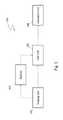
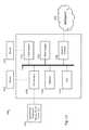
- FIG. 1is a system-level diagram for an anomaly detection system in accordance with an embodiment
- FIG. 2is a component diagram of a Computer-Aided Detection (CAD) unit in accordance with an embodiment
- FIG. 3is a component diagram of a detection unit in accordance with an embodiment
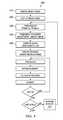
- FIG. 4contains a flowchart for an overall mass detection and classification process according to an embodiment
- FIG. 5illustrates a process for compensating for large-scale intensity gradients in a mammogram due to variations in tissue thickness near the breast boundary
- FIG. 6contains a flowchart describing further details in a potential mass detection process
- FIG. 7depicts an exemplary mass signature as obtained in an iteration of an embodiment
- FIG. 8illustrates a breast coordinate system used in the embodiments.
- FIGS. 9 a and 9 billustrate a classifier probability unit in accordance with an embodiment
- FIG. 10illustrates a closed form PDF and a histogram of a sample distribution drawn from the probability distribution
- FIG. 11shows, conceptually, estimation of a sigma value for a hypothetical one-dimensional distribution expressed by a set of representation points
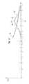
- FIG. 12shows application of the FIG. 11 sigma value to estimation of the PDF at the evaluation point
- FIG. 13is a block diagram of a desktop computing device in accordance with an embodiment of the present invention.
- embodiments discussed hereinare generally described in terms of assisting medical personnel in the examination of breast x-ray images, such as those that may be obtained in the course of performing a mammogram. Other embodiments, however, may be used for other situations, including, for example, detecting anomalies in other tissues such as lung tissue, any type of image analysis for statistical anomalies, and the like.
- the system 100includes an imaging unit 102 , a digitizer 104 , and a computer aided detection (CAD) unit 106 .
- the imaging unit 102captures one or more images, such as x-ray images, of the area of interest, such as the breast tissue.
- a series of four x-ray imagesmay be taken while the breast is compressed to spread the breast tissue, thereby aiding in the detection of anomalies.
- the series of four x-ray imagesinclude a top-down image, referred to as a cranio caudal (CC) image, for each of the right and left breasts, and an oblique angled image taken from the top of the sternum angled downwards toward the outside of the body, referred to as the medio lateral oblique (MLO) image, for each of the right and left breasts.
- CCcranio caudal
- MLOmedio lateral oblique
- the one or more imagesmay be embodied on film or digitized. Historically the one or more images are embodied as x-ray images on film, but current technology allows for x-ray images to be captured directly as digital images in much the same way as modern digital cameras. As illustrated in FIG. 1 , a digitizer 104 allows for digitization of film images into a digital format.
- the digital imagesmay be formatted in any suitable format, such as industry standard Digital Imaging and Communications in Medicine (DICOM) format.
- DICOMDigital Imaging and Communications in Medicine
- the digitized imagese.g., the digitized film images or images captured directly as digital images, are provided to a Computer-Aided Detection (CAD) unit 106 .
- the CAD unit 106processes the one or more images to detect possible locations of various types of anomalies, such as calcifications, relatively dense regions, distortions, and/or the like.
- locations of the possible anomalies, and optionally the digitized imagesare provided to an evaluation unit 108 for viewing by a radiologist, the attending doctor, or other personnel, with or without markings indicating positions of any detected possible anomalies.
- the evaluation unit 108may comprise a display, a workstation, portable device, and/or the like.
- FIG. 2illustrates components that may be utilized by the CAD unit 106 (see FIG. 1 ) in accordance with an embodiment.
- the CAD unit 106includes a segmentation unit 202 , one or more detection units 204 a - 204 n , and one or more display pre-processors 206 a - 206 n .
- an x-ray image, or other imagemay include regions other than those regions of interest.
- an x-ray image of a breastmay include background regions as well as other structural regions such as the pectoral muscle.
- a search areae.g., a bounded region defining the breast tissue, on which the one or more detection units 204 a - 204 n is to analyze for anomalies.
- the one or more detection units 204 a - 204 canalyze the one or more images, or specific regions as defined by the segmentation unit 202 , to detect specific types of features that may indicate one or more specific types of anomalies in the patient.
- the detection units 204 a - 204 nmay comprise a calcification unit, a density (mass) unit, and a distortion unit.
- the human bodyoften reacts to cancerous cells by surrounding the cancerous cells with calcium, creating micro-calcifications. These micro-calcifications may appear as small, bright regions in the x-ray image.
- the calcification unitdetects and identifies these regions of the breast as possible micro-calcifications.
- the density unitanalyzes the one or more breast x-ray images to detect relatively dense regions in the one or more images. Because the random overlap of normal breast tissue may sometimes appear suspicious, in some embodiments the density unit may correlate different views of an object, e.g., a breast, to determine if the dense region is present in other corresponding views. If the dense region appears in multiple views, then there is a higher likelihood that the region is truly malignant.
- the distortion unitdetects structural defects resulting from cancerous cells effect on the surrounding tissue. Cancerous cells frequently have the effect of “pulling in” surrounding tissue, resulting in spiculations that appear as a stretch mark, star pattern, or other linear line patterns.
- the detection units 204 a - 204 ne.g., the calcification unit, the density unit, and the distortion unit, are provided for illustrative purposes only and that other embodiments may include more or fewer detection units. It should also be noted that some detection units may interact with other detection units, as indicated by the dotted line 208 .
- the detection units 204 a - 204 nare discussed in greater detail below with reference to FIG. 3 .
- the display pre-processors 206 a - 206 ncreate image data to indicate the location and/or the type of anomaly. For example, micro-calcifications may be indicated by a line encircling the area of concern by one type of line (e.g., solid lines), while spiculations (or other type of anomaly) may be indicated by a line encircling the area of concern by another type of line (e.g., dashed lines).
- one type of linee.g., solid lines
- spiculationsor other type of anomaly
- FIG. 3illustrates components of that may be utilized for each of the detection units 204 a - 204 n in accordance with an embodiment.
- each of the detection units 204 a - 204 nmay include a detector 302 , a feature extractor 304 , and a classifier 306 .
- the detector 302analyzes the image to identify attributes indicative of the type of anomaly that the detection unit is designed to detect, such as calcifications, and the feature extractor 304 extracts predetermined features of each detected region.
- the predetermined featuresmay include the size, the signal-to-noise ratio, location, and the like.
- the classifier 306examines each extracted feature from the feature extractor 304 and determines a probability that the extracted feature is an abnormality. Once the probability is determined, the probability is compared to a threshold to determine whether or not a detected region is to be reported as a possible area of concern.
- a suitable segmentation unit 202is specified in U.S. Provisional Application Ser. Nos. 61/400,573 and 61/398,571, suitable detection units for use in detecting and classifying microcalcifications are specified in U.S. Provisional Application Ser. Nos. 61/343,557 and 61/343,609 and co-filed U.S. patent application Ser. No. 13/695,347, a suitable detection unit for detecting and classifying spiculated malignant masses is specified in U.S. Provisional Application Ser. No. 61/395,029 and co-filed U.S. patent application Ser. No. 13/695,369, a suitable probability density function estimator is specified in U.S. Provisional Application Ser. No.
- FIG. 4contains a flowchart 400 for a detection/classification process according to an embodiment.
- a first step 410bright areas representing strong edges (typically image artifacts), bright lines such as skin folds, and large bright areas are removed from the image. Such areas are readily recognizable by second derivative outliers, with confirmation features such as linearity, orientation, or a “V” shape in the case of a skin fold, aiding recognition.
- the systemmarks, on a valid pixel image, pixels belonging to these types of signatures as invalid. Once marked as invalid, such pixels are not used in mass detection to prevent their extremely strong signatures from masking nearby weak signatures of interest.
- An optional step 420is an intensity-flattening step for the breast tissue area. This step estimates a compensation for the decrease in tissue thickness near the skin line, which results in additional image exposure and density near the breast boundary.
- FIG. 5illustrates details in the intensity-flattening process.
- the skin lineis used as a starting point to create a distance-to-boundary map 510 of the breast tissue. Pixels along the skin line are assigned a zero distance in the map 510 , pixels that are a valid part of the breast and touching the zero-distance pixels are assigned a unit distance, pixels touching the unit-distance pixels are assigned a two-unit distance, and so forth, with the process continuing until all valid pixels are assigned a distance (optionally, the process can be stopped early at some fixed distance beyond which a high confidence exists that imaged thickness remains constant).
- the image intensityis sampled along a large number of lines orthogonal to the skin line, all along the skin line, as shown in process 520 .
- the samplesare collected in data structure groups according to the skin line distance written in map 510 .
- scatter plot 530illustrates, intuitively, a typical distribution of intensity versus boundary distance, D.
- individual pixel intensityvaries according to the structure crossed in each sample line, with a general underlying trend representing an “undersignal.”
- the undersignalrepresents the x-ray absorption expected for minimally dense tissue of a thickness found a given distance from the skin line. It is this undersignal that is estimated and removed.
- One approachcan define the minimum pixel intensity at each distance D as the undersignal at that distance. Due to noise, uncertainty in skin line determination, variations along the breast contour in how quickly the thickness tapers toward the skin line, etc., this approach can lack robustness (although it may work well with some digital imagery).
- An alternate embodimentsorts the samples into ascending order for each D, and weights samples at distances close to D according to a weighting function 532 .
- the undersignal pointis selected at the intensity that is above a given percentage P of the weighted pixels (at D and surrounding distances), with values of P of about 30% exhibiting good performance.
- the calculated undersignalmay not monotonically increase with increasing D, even though the actual undersignal would be expected to increase monotonically.
- a smoothing stepforces monotonicity upon the undersignal 534 , by starting at the largest D modeled and moving toward 0. At each point D, a smoothed undersignal 536 adopts the same value as undersignal 534 , unless undersignal 534 increases.
- smoothed undersignal 536remains constant until D decreases to a point that undersignal 534 drops to at least the value of smoothed undersignal 536 . At this point, smoothed undersignal 536 will continue to track undersignal 534 again until the next upwards excursion of undersignal 534 .
- the smoothed undersignal 536is combined with distance-to-boundary map 510 to create a breast ⁇ image 540 that describes an intensity that is to be subtracted from that image pixel to remove the undersignal.
- the final, adjusted image 550is created by subtracting the breast ⁇ image 540 from the input image 202 .
- adjusted image 550is passed to mass detection, which begins at step 430 .
- Mass detectionattempts to find objects at a selectable number of scales.
- M scalesare attempted, from 4 mm to 50 mm, with each scale spaced from its neighbors by a multiplicative scale factor 4 ⁇ square root over (2) ⁇ .
- step 440the adjusted image 550 is subsampled by an integer factor related to the scale, and then smoothed with a Gaussian function related to the subsample factor.
- step 450 of FIG. 4second derivative (D 2 ) measurements are taken at two scales, as shown in FIG. 6 block 452 .
- the fine scalecalculates second derivatives at three image points spaced at W/ 8 , where W is the scale of interest.
- the large scalecalculates second derivatives at three image points spaced at W/ 3 .
- the second derivativesare calculated at multiple orientations.
- the finer-scaled D 2 measurementsare used to build a noise map for the scale. From among all orientations tested, the minimum absolute D 2 measurement is saved in a noise map for use in SNR (Signal-to-Noise Ratio) measurements.
- SNRSignal-to-Noise Ratio
- Min ND2minimum negative second derivative
- Max ND 2 value(most convex down curvature recorded) is taken as a strength measure for the convex down area.
- the N areas producing the highest strength measures at the current scaleare selected as objects for further processing.
- the object boundariesare refined to remove high frequency corners, and then resampled at 0.5-pixel increments, such as shown for object 730 in FIG. 7 .
- Strength measurementsare made around convex segments of object 730 at the boundary pixel locations, from the subsampled image 700 .
- Each boundary pixelis compared to the intensity at several locations along a line 740 orthogonal to the boundary.
- an outer contrastis calculated, and the minimum outer contrast (the background is expected to have a lower intensity than the object) is saved.
- For each boundary pixelits strength is defined as the minimum of its inner and outer strengths.
- the SNR of the objectis defined as its minimum boundary strength, divided by the standard deviation of the D 2 measurements in boundary region 710 .
- the featuresinclude search width index, x position (e.g., nipple distance), y position, SNR, object rank, relative arc length, dip SNR, global SNR, and other side SNR. Each will be described in turn.
- Search width indexdescribes the scale at which the object was detected.
- Nipple distance and y positiondescribe the location of the object in the breast, in a novel breast coordinate system.
- the novel coordinate systemallows mass location to form a meaningful and classifiable feature, despite the large variation in patient size, breast size, and breast shape.
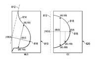
- Typical radiological views for mammographyinclude a mediolateral oblique view (MLO, shown as view 810 in FIG. 8 ) and a cranio-caudal view (CC, shown as view 820 in FIG. 8 ). Other, less-common views are also occasionally taken, and can be expressed in similar coordinate systems.
- MLOmediolateral oblique view
- CCcranio-caudal view
- the MLO viewis segmented to find the pectoral line 812 and the skin line 814 .
- the nipple 816is defined in the coordinate system as the point on the skin line furthest from the pectoral line 812 , measured orthogonal to the pectoral line.
- the x-axis of the coordinate systemis the line running from the nipple point 816 to the pectoral line 812 , with the value 0 lying at the nipple point and the value 100 lying at the pectoral line.
- the pectoral linemay not actually be visible in the image at the x-axis position, but is assumed to extend as far as needed below the visible portion to form the coordinate system.
- the x-coordinate of any point in the breastis the percentage of the distance from the nipple (front) of the breast to the pectoral line (back) of the breast.
- the y-coordinate in the breast coordinate systemis also expressed on a 0 to 100 scale (points below the x-axis are expressed on a 0 to ⁇ 100 scale).
- the scalechanges, however, with x-value, as 100 or ⁇ 100 is defined, for a given x-coordinate, as the point orthogonal to the x-axis at the x-value where the skin line is crossed. Since the cross-sectional profile of the breast generally expands as one traverses the image from the nipple point to the pectoral line, the scale units near the pectoral line are significantly larger than the scale units near the nipple point.
- the normalized scalingallows statistical frequency of object occurrence as a function of breast position to be tabulated without regard to breast shape and size discrepancies.
- Several exemplary coordinatesare shown on MLO view 810 .
- the pectoral lineis often not visible.
- the coordinate system for the CC viewassumes that the pectoral line 812 is perpendicular to the view edge, and therefore the nipple point 816 is the point on skin line 818 that is furthest from the image edge.
- the coordinate systemalso assumes that the pectoral line 812 is located the same absolute distance from the nipple point as that measured in MLO view 810 . Assuming this x-axis definition, a similar x-axis-to-skin-line y-coordinate system as that used in the MLO view is adopted for the CC view.
- Several exemplary coordinatesare shown on MLO view 820 .
- the object rankis a number between 1 and 9, indicating its relative position among the objects detected at this scale.
- the relative arc lengthis calculated as l/ ⁇ w, where w is the scale and l is the boundary length of the object.
- DIP SNRis a weighted percentile of the ND 2 values measured at the W/ 8 scale, divided by the median noise value for region 710 .
- Global SNRis defined as the strength of the segment, divided by the standard deviation of Min ND 2 , taken over the entire breast.
- Other side SNRis measured, using breast coordinates, from the same scale and approximately the same location in a corresponding mammogram of the opposite breast.
- Other side SNRprovides information to the classifier indicating that the patient may have bilaterally similar structure at that scale in both breasts, which may tend to indicate a non-malignancy.
- the same object detection process and feature calculatorare run on a training set containing a large number of radiographic images, with and without masses indicative of malignancy.
- Human-interactive classificationusing one or more individuals with training in interpreting radiological images, indicates malignancy or non-malignancy for each object found in the training set.
- PDFmultidimensional probability density function
- FIGS. 9 a and 9 billustrate an example of a classifier 306 that may be used in an embodiment.
- the classifierestimates the probability that an evaluation point belongs to a particular class by first estimating the PDF value for each of two or more classes and then combining the different class PDF values into a probability.
- the combining of PDF values to estimate a probabilitycan be performed using techniques such as the well-known Bayes' law.
- the classifiercould also use the PDF estimates to generate likelihood ratios instead of probability values.
- the classifier 306includes one or more PDF units 900 providing PDF estimates to a Probability unit 901 .
- the PDF units 900determine a PDF estimate for each possible classification for an object.
- the classifier 306is utilized to classify a microcalcification
- a classifier probability unit 900that may be used by the classifier 306 (see FIG. 3 ) in accordance with an embodiment is shown, although different classifier probability units may be utilized.
- a neighborhood definition unit 902 of the PDF estimator unit 900functionally defines neighborhood sizes for each representation point or bin of representation points. In some embodiments a variable neighborhood size may be desirable in order to allow for a functional description that better fits the actual measured feature data.
- the neighborhood definition unit 902evaluates training data received, e.g., from a database, and determines the appropriate neighborhood sizes for the representation points included in the training data.
- the neighborhood definition unit 902provides vector ⁇ right arrow over (s) ⁇ P (a vector representing scale parameters for each representation point or bin of representation points for each feature or dimension) to a neighborhood determination unit 904 .
- the neighborhood definition unit 902is performed off-line and the results, e.g., ⁇ right arrow over (s) ⁇ P , are stored, such as being stored in a database, for later access.
- the vector ⁇ right arrow over (s) ⁇ Pis utilized by the neighborhood determination unit 904 to determine a scale parameter vector ⁇ right arrow over ( ⁇ ) ⁇ S —the size of the neighborhood to be used for the evaluation point x 0 for each dimension or feature.
- the scale parameter vector ⁇ right arrow over ( ⁇ ) ⁇ Sis provided to a weight determination unit 906 to determine weights w i , which specifies how much weight to allocate to representation points of the training data. Once determined, the weights w i are provided to a local estimator 908 . The local estimator 908 applies the weights w i to the training data to determine a PDF estimate for the point x 0 , which may be stored, e.g., in a database. The following paragraphs provide greater detail.
- Embodiments described hereintake a novel approach to PDF estimation. Instead of estimating and storing a complete PDF, a data set is stored that allows on-the-fly computation of a PDF estimator function for any specific local region in the PDF.
- the amount of data required to store an estimated PDF in this mannercan be on the order of n ⁇ M, where n is the dimensionality of the system and M is a number of representation points, r i .
- Each representation pointrepresents one or more samples from the actual distribution that is being estimated. For instance, each sample in a sample set can receive its own representation point, with a unit weighting. Each sample can alternately be expressed through a representation point with a weight less than one.
- each of the two samplescan be given a representation point with a weight of 0.5.
- a representation pointcan “bin” several samples that are close in measurement space, by replacing the samples with a single representation point with a weight equal to the weights of the individual samples.
- the actual multidimensional sample value for a binned samples representation pointcan be the center of the bin, the mean of the binned samples, the median of the binned sample values in each dimension, etc.
- One inputis the evaluation point, x 0 , at which the PDF is to be estimated.
- Another inputis a vector ⁇ right arrow over (s) ⁇ P , provided by the neighborhood definition unit 902 in an embodiment, represents a set of scalar parameters that allow computation of a scale parameter vector, ⁇ right arrow over ( ⁇ ) ⁇ S .
- the scale parameter vectordetermines which of the representation points will be used in the estimation, and also can be a parameter for a function that determines the weight to be applied to each included point.
- Another inputis the weighting function, g( ⁇ right arrow over ( ⁇ ) ⁇ S ), that will actually be applied to the representation points used in the estimation.
- the final inputis a parameterized estimator function, ⁇ (x 0 , ⁇ ), where ⁇ is a parameter matrix for the function.
- FIG. 10shows a generic PDF 1000 for a one-dimensional random variable, superimposed on a histogram of a sample distribution drawn from the population of samples 1002 of the same random variable.
- the histogramwill tend towards a quantized version of the shape of PDF 1000 , which may be estimated by a prior art technique such as a Parzen window.
- Towards the tails of PDF 1000such an approach has difficulty producing a reliable estimate.
- the small number of samples often present in the tailsmeans that in the tails, a simple windowed estimate either has high variance, due to the small number of samples, or fails to account for the true shape of the actual PDF, due to the application of a large linear window.
- the input dataincludes pre-calculated parameters from which an appropriate scale parameter can be calculated for any input evaluation point by, for example, the neighborhood determination unit 904 .
- the scale parameterwill be larger towards the tails of the distribution, and smaller in more data-rich areas of the representation point space.
- each representation pointstores parameters that can be used to calculate a scale parameter vector on the fly.
- the scale parameter functionallows calculation of a scale parameter.
- the scale parameter for use with an evaluation pointcan thus be defined as the minimum scale parameter function value ⁇ i (x 0 ), evaluated for all i, which minimum values ⁇ right arrow over ( ⁇ ) ⁇ S are provided to the weight determination unit 906 .
- the scale parametermay need only be evaluated for representation points close to the evaluation point. This can be seen by an inspection of FIG. 12 , where scale parameter functions ⁇ i (x) are plotted for each evaluation point ( ⁇ 1 (x), for r 1 , ⁇ 2 (x), for r 2 , ⁇ 3 (x), for r 3 , are labeled).
- the value ⁇ 3 (x 0 )is lower than the scale parameter function values associated with all other representation points, and is thus selected as the scale parameter for evaluation point x 0 .
- the different scale parameter function valuescould be combined with mathematical functions other than “min” (for example, the mean or a particular percentile of the different values could be used).
- the scale parametercan next be used to limit the representation points that will be used to estimate the PDF at the evaluation point. For instance, a practical rule of thumb based on distance from the evaluation point, such as a multiple of the scale factor, can be used to exclude representation points that practically cannot affect the calculation as illustrated in FIG. 12 , thus saving computation time. Alternately, all representation points can be evaluated, no matter how far they lie from the evaluation point.
- the selected, weighted representation pointsare used to calculate a parameter matrix, ⁇ , for the parameterized estimator function ⁇ (x, ⁇ ) calculated by the local estimator 908 .
- the parameter matrixis calculated to maximize the function:
- the weight function g( )is a Gaussian function
- h( )is a log function
- ⁇ ( )is a second-order exponential function:
- N1 N ⁇ ⁇ i ⁇ g ⁇ ( r i ; x 0 , ⁇ ⁇ ( x 0 ) ) ⁇ x ⁇ g ⁇ ( x ; x 0 , ⁇ ⁇ ( x 0 ) ) ⁇ e ⁇ 1 ⁇ x 2 + ⁇ 2 ⁇ x and N is the number of representation points.
- the general approach described abovecan also be applied where the PDF has a zero value in some parts of n-dimensional space.
- the approachcan also be applied where h, g, or f are not in a directly solvable form.
- the parameter matrixcan be approximated using numerical methods, such as Newton-Rhapson optimization.
- PDF techniquesA wide variety of applications exist for PDF techniques according to an embodiment. Some disciplines that can benefit from accurate PDF estimation include pattern recognition, classification, estimation, computer vision, image processing, and signal processing.
- PDF estimation dataadd practicality for PDF data set compact storage, update distribution, the inclusion of additional discriminant variables and/or classes, etc.
- the equation used to solve for the estimator function parameterscan be defined such that its minimization selects the parameter matrix.
- the scale parameter for a given evaluation pointcan be calculated at runtime from the representation points directly, although good solutions for the scale parameter may be more costly to calculate without precalculation of per-representation point functions.
- FIG. 13is a block diagram of a computing system 1300 that may also be used in accordance with an embodiment. It should be noted, however, that the computing system 1300 discussed herein is provided for illustrative purposes only and that other devices may be used.
- the computing system 1300may comprise, for example, a desktop computer, a workstation, a laptop computer, a personal digital assistant, a dedicated unit customized for a particular application, or the like. Accordingly, the components of the computing system 1300 disclosed herein are for illustrative purposes only and other embodiments of the present invention may include additional or fewer components.
- the computing system 1300comprises a processing unit 1310 equipped with one or more input devices 1312 (e.g., a mouse, a keyboard, or the like), and one or more output devices, such as a display 1314 , a printer 1316 , or the like.
- the processing unit 1310includes a central processing unit (CPU) 1318 , memory 1320 , a mass storage device 1322 , a video adapter 1324 , an I/O interface 1326 , and a network interface 1328 connected to a bus 1330 .
- the bus 1330may be one or more of any type of several bus architectures including a memory bus or memory controller, a peripheral bus, video bus, or the like.
- the CPU 1318may comprise any type of electronic data processor.
- the CPU 1318may comprise a processor (e.g., single core or multi-core) from Intel Corp. or Advanced Micro Devices, Inc., a Reduced Instruction Set Computer (RISC), an Application-Specific Integrated Circuit (ASIC), or the like.
- the memory 1320may comprise any type of system memory such as static random access memory (SRAM), dynamic random access memory (DRAM), synchronous DRAM (SDRAM), read-only memory (ROM), a combination thereof, or the like.
- the memory 1320may include ROM for use at boot-up, and DRAM for data storage for use while executing programs.
- the memory 1320may include one of more non-transitory memories.
- the mass storage device 1322may comprise any type of storage device configured to store data, programs, and other information and to make the data, programs, and other information accessible via the bus 1328 .
- the mass storage device 1322is configured to store the program to be executed by the CPU 1318 .
- the mass storage device 1322may comprise, for example, one or more of a hard disk drive, a magnetic disk drive, an optical disk drive, or the like.
- the mass storage device 1322may include one or more non-transitory memories.
- the video adapter 1324 and the I/O interface 1326provide interfaces to couple external input and output devices to the processing unit 1310 .
- input and output devicesinclude the display 1314 coupled to the video adapter 1324 and the mouse/keyboard 1312 and the printer 1316 coupled to the I/O interface 1326 .
- Other devicesmay be coupled to the processing unit 1310 .
- the network interface 1328which may be a wired link and/or a wireless link, allows the processing unit 1310 to communicate with remote units via the network 1332 .
- the processing unit 1310is coupled to a local-area network or a wide-area network to provide communications to remote devices, such as other processing units, the Internet, remote storage facilities, or the like
- the computing system 1300may include other components.
- the computing system 1300may include power supplies, cables, a motherboard, removable storage media, cases, a network interface, and the like. These other components, although not shown, are considered part of the computing system 1300 .
- any one of the components of the computing system 1300may include multiple components.
- the CPU 1318may comprise multiple processors
- the display 1314may comprise multiple displays, and/or the like.
- the computing system 1300may include multiple computing systems directly coupled and/or networked.
- one or more of the componentsmay be remotely located.
- the displaymay be remotely located from the processing unit.
- display informatione.g., locations and/or types of abnormalities, may be transmitted via the network interface to a display unit or a remote processing unit having a display coupled thereto.
Landscapes
- Engineering & Computer Science (AREA)
- Physics & Mathematics (AREA)
- Theoretical Computer Science (AREA)
- General Physics & Mathematics (AREA)
- Computer Vision & Pattern Recognition (AREA)
- General Health & Medical Sciences (AREA)
- Health & Medical Sciences (AREA)
- Evolutionary Computation (AREA)
- Artificial Intelligence (AREA)
- Life Sciences & Earth Sciences (AREA)
- Nuclear Medicine, Radiotherapy & Molecular Imaging (AREA)
- Radiology & Medical Imaging (AREA)
- Medical Informatics (AREA)
- Quality & Reliability (AREA)
- Biodiversity & Conservation Biology (AREA)
- Data Mining & Analysis (AREA)
- Biomedical Technology (AREA)
- Molecular Biology (AREA)
- Multimedia (AREA)
- Probability & Statistics with Applications (AREA)
- Software Systems (AREA)
- Evolutionary Biology (AREA)
- Bioinformatics & Computational Biology (AREA)
- Bioinformatics & Cheminformatics (AREA)
- General Engineering & Computer Science (AREA)
- Apparatus For Radiation Diagnosis (AREA)
- Image Processing (AREA)
- Image Analysis (AREA)
- Complex Calculations (AREA)
Abstract
Description
where h( ) is a monotonic function.
and N is the number of representation points.
Claims (24)
Priority Applications (1)
| Application Number | Priority Date | Filing Date | Title |
|---|---|---|---|
| US13/695,357US9262822B2 (en) | 2010-04-30 | 2011-04-29 | Malignant mass detection and classification in radiographic images |
Applications Claiming Priority (10)
| Application Number | Priority Date | Filing Date | Title |
|---|---|---|---|
| US34355710P | 2010-04-30 | 2010-04-30 | |
| US34360910P | 2010-05-02 | 2010-05-02 | |
| US34355210P | 2010-05-02 | 2010-05-02 | |
| US34360810P | 2010-05-02 | 2010-05-02 | |
| US39502910P | 2010-05-06 | 2010-05-06 | |
| US39857110P | 2010-06-25 | 2010-06-25 | |
| US39909410P | 2010-07-07 | 2010-07-07 | |
| US40057310P | 2010-07-28 | 2010-07-28 | |
| PCT/US2011/034698WO2011137409A1 (en) | 2010-04-30 | 2011-04-29 | Malignant mass detection and classification in radiographic images |
| US13/695,357US9262822B2 (en) | 2010-04-30 | 2011-04-29 | Malignant mass detection and classification in radiographic images |
Publications (2)
| Publication Number | Publication Date |
|---|---|
| US20130202165A1 US20130202165A1 (en) | 2013-08-08 |
| US9262822B2true US9262822B2 (en) | 2016-02-16 |
Family
ID=44861947
Family Applications (7)
| Application Number | Title | Priority Date | Filing Date |
|---|---|---|---|
| US13/695,357Active2031-09-17US9262822B2 (en) | 2010-04-30 | 2011-04-29 | Malignant mass detection and classification in radiographic images |
| US13/695,369Active2031-11-19US8923594B2 (en) | 2010-04-30 | 2011-04-29 | Spiculated malignant mass detection and classification in radiographic image |
| US13/695,351Active2031-10-07US9076197B2 (en) | 2010-04-30 | 2011-04-29 | Probability density function estimation |
| US13/695,347Active2031-08-21US8855388B2 (en) | 2010-04-30 | 2011-04-29 | Microcalcification detection classification in radiographic images |
| US13/168,614Active2032-09-10US8675934B2 (en) | 2010-04-30 | 2011-06-24 | Breast skin line detection in radiographic images |
| US14/507,575ActiveUS9256941B2 (en) | 2010-04-30 | 2014-10-06 | Microcalcification detection and classification in radiographic images |
| US14/542,361ActiveUS8958625B1 (en) | 2010-04-30 | 2014-11-14 | Spiculated malignant mass detection and classification in a radiographic image |
Family Applications After (6)
| Application Number | Title | Priority Date | Filing Date |
|---|---|---|---|
| US13/695,369Active2031-11-19US8923594B2 (en) | 2010-04-30 | 2011-04-29 | Spiculated malignant mass detection and classification in radiographic image |
| US13/695,351Active2031-10-07US9076197B2 (en) | 2010-04-30 | 2011-04-29 | Probability density function estimation |
| US13/695,347Active2031-08-21US8855388B2 (en) | 2010-04-30 | 2011-04-29 | Microcalcification detection classification in radiographic images |
| US13/168,614Active2032-09-10US8675934B2 (en) | 2010-04-30 | 2011-06-24 | Breast skin line detection in radiographic images |
| US14/507,575ActiveUS9256941B2 (en) | 2010-04-30 | 2014-10-06 | Microcalcification detection and classification in radiographic images |
| US14/542,361ActiveUS8958625B1 (en) | 2010-04-30 | 2014-11-14 | Spiculated malignant mass detection and classification in a radiographic image |
Country Status (6)
| Country | Link |
|---|---|
| US (7) | US9262822B2 (en) |
| EP (4) | EP2564352A1 (en) |
| JP (4) | JP5801379B2 (en) |
| CN (4) | CN102934126A (en) |
| CA (4) | CA2797238A1 (en) |
| WO (4) | WO2011137409A1 (en) |
Cited By (1)
| Publication number | Priority date | Publication date | Assignee | Title |
|---|---|---|---|---|
| US10475174B2 (en) | 2017-04-06 | 2019-11-12 | General Electric Company | Visual anomaly detection system |
Families Citing this family (81)
| Publication number | Priority date | Publication date | Assignee | Title |
|---|---|---|---|---|
| EP2460468A1 (en) | 2005-07-01 | 2012-06-06 | Impedimed Limited | Monitoring system |
| JP5208749B2 (en) | 2005-10-11 | 2013-06-12 | インペダイムド・リミテッド | Hydration status monitoring |
| WO2008128281A1 (en) | 2007-04-20 | 2008-10-30 | Impedimed Limited | Monitoring system and probe |
| US20110046505A1 (en) | 2007-08-09 | 2011-02-24 | Impedimed Limited | Impedance measurement process |
| US9615767B2 (en) | 2009-10-26 | 2017-04-11 | Impedimed Limited | Fluid level indicator determination |
| CA2778770A1 (en) | 2009-11-18 | 2011-05-26 | Chung Shing Fan | Signal distribution for patient-electrode measurements |
| GB2475722B (en)* | 2009-11-30 | 2011-11-02 | Mirada Medical | Measurement system for medical images |
| US8675933B2 (en) | 2010-04-30 | 2014-03-18 | Vucomp, Inc. | Breast segmentation in radiographic images |
| CN102934126A (en) | 2010-04-30 | 2013-02-13 | 沃康普公司 | Microcalcification detection and classification in radiographic images |
| US9256799B2 (en) | 2010-07-07 | 2016-02-09 | Vucomp, Inc. | Marking system for computer-aided detection of breast abnormalities |
| EP2790576A4 (en) | 2011-12-14 | 2015-07-08 | Intersection Medical Inc | Devices, systems and methods for determining the relative spatial change in subsurface resistivities across frequencies in tissue |
| JP6175071B2 (en)* | 2011-12-22 | 2017-08-02 | コーニンクレッカ フィリップス エヌ ヴェKoninklijke Philips N.V. | Chest image processing and display |
| EP2629263B1 (en)* | 2012-02-17 | 2015-06-03 | Agfa HealthCare | Method for defining a region of interest in a radiation image of a breast |
| EP2631873B1 (en)* | 2012-02-27 | 2015-12-16 | Agfa Healthcare | Image alignment of breast images |
| WO2013179963A1 (en)* | 2012-05-28 | 2013-12-05 | 富士フイルム株式会社 | Image-processing device, imaging device and image-processing method, as well as program |
| JP5844296B2 (en)* | 2012-06-11 | 2016-01-13 | 富士フイルム株式会社 | Radiation image processing apparatus and method |
| US9213781B1 (en) | 2012-09-19 | 2015-12-15 | Placemeter LLC | System and method for processing image data |
| US8942447B2 (en)* | 2012-11-07 | 2015-01-27 | Sony Corporation | Method and apparatus for tissue region identification |
| WO2016109768A1 (en)* | 2014-12-31 | 2016-07-07 | Robert Bosch Gmbh | System and method of shadow effect generation for concave objects with dynamic lighting in three-dimensional graphics |
| US9886790B2 (en) | 2013-03-14 | 2018-02-06 | Robert Bosch Gmbh | System and method of shadow effect generation for concave objects with dynamic lighting in three-dimensional graphics |
| EP3035850B1 (en) | 2013-08-20 | 2020-05-13 | Densitas Incorporated | Methods and systems for determining breast density |
| EP3072082A4 (en)* | 2013-11-19 | 2017-09-13 | Vucomp, Inc. | Obtaining breast density measurements and classifications |
| WO2015087961A1 (en) | 2013-12-12 | 2015-06-18 | 三菱化学株式会社 | Iridium complex compound, method for producing said compound, composition containing said compound, organic electroluminescent element, display device, and lighting device |
| US9474497B2 (en)* | 2014-01-15 | 2016-10-25 | Agfa Healthcare | Method and system for generating pre-scaled images for a series of mammography images |
| US9704059B2 (en) | 2014-02-12 | 2017-07-11 | International Business Machines Corporation | Anomaly detection in medical imagery |
| CN106163404B (en) | 2014-04-08 | 2019-04-23 | Icad股份有限公司 | Lung segmentation and bone suppression techniques for radiographic images |
| KR102265279B1 (en)* | 2014-05-29 | 2021-06-16 | 삼성전자주식회사 | X-ray imaging apparatus and control method for the same |
| WO2015184440A2 (en) | 2014-05-30 | 2015-12-03 | Placemeter Inc. | System and method for activity monitoring using video data |
| JP6383182B2 (en)* | 2014-06-02 | 2018-08-29 | キヤノン株式会社 | Image processing apparatus, image processing system, image processing method, and program |
| WO2015196300A1 (en) | 2014-06-27 | 2015-12-30 | Sunnybrook Research Institute | Systems and methods for generating an imaging biomarker that indicates detectability or conspicuity of lesions in a mammographic image |
| JP6395481B2 (en)* | 2014-07-11 | 2018-09-26 | キヤノン株式会社 | Image recognition apparatus, method, and program |
| US10039513B2 (en)* | 2014-07-21 | 2018-08-07 | Zebra Medical Vision Ltd. | Systems and methods for emulating DEXA scores based on CT images |
| US10588589B2 (en) | 2014-07-21 | 2020-03-17 | Zebra Medical Vision Ltd. | Systems and methods for prediction of osteoporotic fracture risk |
| JP6027065B2 (en)* | 2014-08-21 | 2016-11-16 | 富士フイルム株式会社 | Similar image search device, method of operating similar image search device, and similar image search program |
| KR102262657B1 (en)* | 2014-10-13 | 2021-06-08 | 삼성전자주식회사 | Plasma processing device |
| EP3224804B1 (en)* | 2014-11-27 | 2021-02-24 | Koninklijke Philips N.V. | Apparatus for determining positions of an interventional instrument in a projection image |
| JP6759550B2 (en) | 2015-03-04 | 2020-09-23 | ソニー株式会社 | Information processing equipment, programs, information processing methods and observation systems |
| US11334751B2 (en) | 2015-04-21 | 2022-05-17 | Placemeter Inc. | Systems and methods for processing video data for activity monitoring |
| US10043078B2 (en)* | 2015-04-21 | 2018-08-07 | Placemeter LLC | Virtual turnstile system and method |
| US10380431B2 (en) | 2015-06-01 | 2019-08-13 | Placemeter LLC | Systems and methods for processing video streams |
| US9918686B2 (en) | 2015-11-16 | 2018-03-20 | International Business Machines Corporation | Automated fibro-glandular (FG) tissue segmentation in digital mammography using fuzzy logic |
| US11568627B2 (en) | 2015-11-18 | 2023-01-31 | Adobe Inc. | Utilizing interactive deep learning to select objects in digital visual media |
| US10192129B2 (en) | 2015-11-18 | 2019-01-29 | Adobe Systems Incorporated | Utilizing interactive deep learning to select objects in digital visual media |
| JP6719724B2 (en)* | 2016-02-05 | 2020-07-08 | 富士ゼロックス株式会社 | Data classifier and program |
| KR20180115725A (en) | 2016-02-08 | 2018-10-23 | 이마고 시스템즈, 인크. | System and method for visualization and characterization of objects in an image |
| WO2017152121A1 (en)* | 2016-03-03 | 2017-09-08 | Geisinger Health System | System and method for automated analysis in medical imaging applications |
| AU2017225901B2 (en)* | 2016-03-03 | 2022-07-28 | Curvebeam Ai Limited | Method and apparatus for identifying and quantifying abnormality |
| CN107992495B (en)* | 2016-10-26 | 2021-01-26 | 腾讯科技(深圳)有限公司 | Data visualization analysis method and device for high-dimensional data set |
| KR102787157B1 (en)* | 2016-12-07 | 2025-03-26 | 삼성전자주식회사 | Methods and devices of reducing structure noises through self-structure analysis |
| US10372876B2 (en) | 2017-01-20 | 2019-08-06 | Agfa Healthcare Inc. | System and method for providing breast image data |
| EP3665620A4 (en)* | 2017-08-07 | 2021-04-21 | Imago Systems, Inc. | SYSTEM AND PROCESS FOR VISUALIZATION AND CHARACTERIZATION OF OBJECTS IN PICTURES |
| EP3669325B1 (en)* | 2017-08-14 | 2023-09-27 | Raytheon Company | Subtraction algorithm for detection of tumors |
| CN110197474B (en)* | 2018-03-27 | 2023-08-25 | 腾讯科技(深圳)有限公司 | Image processing method and device and training method of neural network model |
| DE102018112215B3 (en)* | 2018-04-30 | 2019-07-25 | Basler Ag | Quantizer determination, computer readable medium, and apparatus implementing at least two quantizers |
| US11244195B2 (en)* | 2018-05-01 | 2022-02-08 | Adobe Inc. | Iteratively applying neural networks to automatically identify pixels of salient objects portrayed in digital images |
| WO2020006514A1 (en)* | 2018-06-29 | 2020-01-02 | Qmenta Inc. | Tumor segmentation tool |
| US11900606B2 (en) | 2018-06-29 | 2024-02-13 | QMENTA, Inc. | Tumor segmentation tool |
| JP6660428B2 (en)* | 2018-08-01 | 2020-03-11 | キヤノン株式会社 | Processing device, processing method, and program |
| US10643746B2 (en)* | 2018-08-17 | 2020-05-05 | Fujifilm Medical Systems U.S.A., Inc. | Image viewer |
| CN110569864A (en)* | 2018-09-04 | 2019-12-13 | 阿里巴巴集团控股有限公司 | Vehicle damage image generation method and device based on GAN network |
| WO2020060046A1 (en)* | 2018-09-20 | 2020-03-26 | 아주대학교 산학협력단 | Convolutional neural network-based mammogram image analysis method using four-channel input, and system therefor |
| US10810737B2 (en)* | 2018-10-18 | 2020-10-20 | International Business Machines Corporation | Automated nipple detection in mammography |
| US11205265B2 (en) | 2018-11-23 | 2021-12-21 | Icad, Inc. | System and method for assessing breast cancer risk using imagery |
| CA3120480A1 (en) | 2018-11-24 | 2020-05-28 | Densitas Incorporated | System and method for assessing medical images |
| US11282208B2 (en) | 2018-12-24 | 2022-03-22 | Adobe Inc. | Identifying target objects using scale-diverse segmentation neural networks |
| CN114127781B (en)* | 2019-06-11 | 2025-08-29 | 直观外科手术操作公司 | Detecting and representing anatomical features of anatomical structures |
| GB201912784D0 (en)* | 2019-09-05 | 2019-10-23 | Volpara Health Tech Limited | Method and system for image normalization |
| US11475558B2 (en) | 2019-11-13 | 2022-10-18 | Raytheon Company | Organ isolation in scan data |
| US11334771B2 (en)* | 2019-12-12 | 2022-05-17 | Vade Usa, Incorporated | Methods, devices and systems for combining object detection models |
| US11282209B2 (en) | 2020-01-10 | 2022-03-22 | Raytheon Company | System and method for generating contours |
| CN111598189B (en)* | 2020-07-20 | 2020-10-30 | 北京瑞莱智慧科技有限公司 | Generative model training method, data generation method, device, medium, and apparatus |
| US11335004B2 (en) | 2020-08-07 | 2022-05-17 | Adobe Inc. | Generating refined segmentation masks based on uncertain pixels |
| CN112288752B (en)* | 2020-10-29 | 2021-08-27 | 中国医学科学院北京协和医院 | Full-automatic coronary calcified focus segmentation method based on chest flat scan CT |
| US11562512B2 (en) | 2020-12-09 | 2023-01-24 | Raytheon Company | System and method for generating and displaying contours |
| US11893745B2 (en) | 2020-12-09 | 2024-02-06 | Raytheon Company | System and method for generating and displaying contours |
| US11676279B2 (en) | 2020-12-18 | 2023-06-13 | Adobe Inc. | Utilizing a segmentation neural network to process initial object segmentations and object user indicators within a digital image to generate improved object segmentations |
| US11875510B2 (en) | 2021-03-12 | 2024-01-16 | Adobe Inc. | Generating refined segmentations masks via meticulous object segmentation |
| US12020400B2 (en) | 2021-10-23 | 2024-06-25 | Adobe Inc. | Upsampling and refining segmentation masks |
| CN115591742B (en)* | 2022-09-30 | 2023-09-12 | 深圳芯光智能技术有限公司 | Automatic control method and system for dispensing machine for dispensing quality identification |
| CN116563170B (en)* | 2023-07-10 | 2023-09-15 | 中国人民解放军空军特色医学中心 | Image data processing method, system and electronic device |
| JP2025138515A (en)* | 2024-03-11 | 2025-09-25 | 富士フイルム株式会社 | Image processing device, radiation image capturing system, and program |
Citations (100)
| Publication number | Priority date | Publication date | Assignee | Title |
|---|---|---|---|---|
| US4907156A (en) | 1987-06-30 | 1990-03-06 | University Of Chicago | Method and system for enhancement and detection of abnormal anatomic regions in a digital image |
| US5109430A (en) | 1986-07-22 | 1992-04-28 | Schlumberger Technologies, Inc. | Mask alignment and measurement of critical dimensions in integrated circuits |
| US5133020A (en) | 1989-07-21 | 1992-07-21 | Arch Development Corporation | Automated method and system for the detection and classification of abnormal lesions and parenchymal distortions in digital medical images |
| US5301129A (en) | 1990-06-13 | 1994-04-05 | Aluminum Company Of America | Video web inspection system employing filtering and thresholding to determine surface anomalies |
| US5359513A (en) | 1992-11-25 | 1994-10-25 | Arch Development Corporation | Method and system for detection of interval change in temporally sequential chest images |
| US5638458A (en) | 1993-11-30 | 1997-06-10 | Arch Development Corporation | Automated method and system for the detection of gross abnormalities and asymmetries in chest images |
| US5729620A (en) | 1993-09-29 | 1998-03-17 | Wang; Shih-Ping | Computer-aided diagnosis system and method |
| US5790690A (en)* | 1995-04-25 | 1998-08-04 | Arch Development Corporation | Computer-aided method for automated image feature analysis and diagnosis of medical images |
| US5828774A (en) | 1993-09-29 | 1998-10-27 | Wang; Shih-Ping | Computer-aided diagnosis system and method |
| US5911014A (en)* | 1996-08-26 | 1999-06-08 | Fuji Photo Film Co., Ltd. | Method and apparatus for extracting an abnormal pattern |
| US5917929A (en) | 1996-07-23 | 1999-06-29 | R2 Technology, Inc. | User interface for computer aided diagnosis system |
| US5982915A (en) | 1997-07-25 | 1999-11-09 | Arch Development Corporation | Method of detecting interval changes in chest radiographs utilizing temporal subtraction combined with automated initial matching of blurred low resolution images |
| US5987094A (en) | 1996-10-30 | 1999-11-16 | University Of South Florida | Computer-assisted method and apparatus for the detection of lung nodules |
| US5999639A (en)* | 1997-09-04 | 1999-12-07 | Qualia Computing, Inc. | Method and system for automated detection of clustered microcalcifications from digital mammograms |
| US6014452A (en) | 1997-07-28 | 2000-01-11 | R2 Technology, Inc. | Method and system for using local attention in the detection of abnormalities in digitized medical images |
| US6075879A (en) | 1993-09-29 | 2000-06-13 | R2 Technology, Inc. | Method and system for computer-aided lesion detection using information from multiple images |
| US6088473A (en) | 1998-02-23 | 2000-07-11 | Arch Development Corporation | Method and computer readable medium for automated analysis of chest radiograph images using histograms of edge gradients for false positive reduction in lung nodule detection |
| US6125194A (en) | 1996-02-06 | 2000-09-26 | Caelum Research Corporation | Method and system for re-screening nodules in radiological images using multi-resolution processing, neural network, and image processing |
| US6138045A (en) | 1998-08-07 | 2000-10-24 | Arch Development Corporation | Method and system for the segmentation and classification of lesions |
| US6141437A (en) | 1995-11-22 | 2000-10-31 | Arch Development Corporation | CAD method, computer and storage medium for automated detection of lung nodules in digital chest images |
| US6198838B1 (en) | 1996-07-10 | 2001-03-06 | R2 Technology, Inc. | Method and system for detection of suspicious lesions in digital mammograms using a combination of spiculation and density signals |
| US6233364B1 (en) | 1998-09-18 | 2001-05-15 | Dainippon Screen Engineering Of America Incorporated | Method and system for detecting and tagging dust and scratches in a digital image |
| US6240201B1 (en) | 1998-07-24 | 2001-05-29 | Arch Development Corporation | Computerized detection of lung nodules using energy-subtracted soft-tissue and standard chest images |
| US6282307B1 (en) | 1998-02-23 | 2001-08-28 | Arch Development Corporation | Method and system for the automated delineation of lung regions and costophrenic angles in chest radiographs |
| US6335980B1 (en) | 1997-07-25 | 2002-01-01 | Arch Development Corporation | Method and system for the segmentation of lung regions in lateral chest radiographs |
| US20020016539A1 (en) | 2000-05-03 | 2002-02-07 | Bernd Michaelis | Method and apparatus for measuring and classifying optically observable changes in skin and mucous membrane |
| US20020041702A1 (en) | 2000-08-31 | 2002-04-11 | Fuji Photo Film Co., Ltd. | Method and system for detecting suspected anomalous shadows |
| US6404908B1 (en) | 1998-05-28 | 2002-06-11 | R2 Technology, Inc. | Method and system for fast detection of lines in medical images |
| US20030007598A1 (en) | 2000-11-24 | 2003-01-09 | U-Systems, Inc. | Breast cancer screening with adjunctive ultrasound mammography |
| US6549646B1 (en) | 2000-02-15 | 2003-04-15 | Deus Technologies, Llc | Divide-and-conquer method and system for the detection of lung nodule in radiological images |
| US6577752B2 (en) | 2001-06-15 | 2003-06-10 | Arch Development Corporation | Automated method and system for the delineation of the chest wall in computed tomography scans for the assessment of pleural disease |
| US6609021B1 (en) | 2002-05-20 | 2003-08-19 | Siemens Corporate Research, Inc. | Pulmonary nodule detection using cartwheel projection analysis |
| US6654728B1 (en) | 2000-07-25 | 2003-11-25 | Deus Technologies, Llc | Fuzzy logic based classification (FLBC) method for automated identification of nodules in radiological images |
| US6683973B2 (en) | 2000-11-21 | 2004-01-27 | Arch Development Corporation | Process, system and computer readable medium for pulmonary nodule detection using multiple-templates matching |
| US6690816B2 (en) | 2000-04-07 | 2004-02-10 | The University Of North Carolina At Chapel Hill | Systems and methods for tubular object processing |
| US6694046B2 (en) | 2001-03-28 | 2004-02-17 | Arch Development Corporation | Automated computerized scheme for distinction between benign and malignant solitary pulmonary nodules on chest images |
| US20040052328A1 (en) | 2002-09-13 | 2004-03-18 | Sabol John M. | Computer assisted analysis of tomographic mammography data |
| US6738499B1 (en) | 1998-11-13 | 2004-05-18 | Arch Development Corporation | System for detection of malignancy in pulmonary nodules |
| US6757415B1 (en)* | 1999-06-23 | 2004-06-29 | Qualia Computing, Inc. | Method for determining features from detections in a digital image using a bauer-fisher ratio |
| US6760468B1 (en) | 1996-02-06 | 2004-07-06 | Deus Technologies, Llc | Method and system for the detection of lung nodule in radiological images using digital image processing and artificial neural network |
| US6766043B2 (en) | 2001-11-23 | 2004-07-20 | R2 Technology, Inc. | Pleural nodule detection from CT thoracic images |
| US20040161141A1 (en) | 2003-02-19 | 2004-08-19 | Agfa-Gevaert | Method of determining the orientation of an image |
| US6795521B2 (en) | 2001-08-17 | 2004-09-21 | Deus Technologies Llc | Computer-aided diagnosis system for thoracic computer tomography images |
| US20050010106A1 (en) | 2003-03-25 | 2005-01-13 | Imaging Therapeutics, Inc. | Methods for the compensation of imaging technique in the processing of radiographic images |
| US20050008211A1 (en) | 2003-07-07 | 2005-01-13 | Deus Technologies, Llc | Lung contrast normalization on direct digital and digitized chest images for computer-aided detection (CAD) of early-stage lung cancer |
| JP2005080758A (en) | 2003-09-05 | 2005-03-31 | Konica Minolta Medical & Graphic Inc | Image processing apparatus |
| US6937776B2 (en)* | 2003-01-31 | 2005-08-30 | University Of Chicago | Method, system, and computer program product for computer-aided detection of nodules with three dimensional shape enhancement filters |
| US20060083418A1 (en) | 2003-02-11 | 2006-04-20 | Qinetiq Limited | Image analysis |
| US7043066B1 (en) | 1998-11-05 | 2006-05-09 | Arch Development Corporation | System for computerized processing of chest radiographic images |
| US7054473B1 (en) | 2001-11-21 | 2006-05-30 | R2 Technology, Inc. | Method and apparatus for an improved computer aided diagnosis system |
| US20060171573A1 (en) | 1997-08-28 | 2006-08-03 | Rogers Steven K | Use of computer-aided detection system outputs in clinical practice |
| US7088850B2 (en) | 2004-04-15 | 2006-08-08 | Edda Technology, Inc. | Spatial-temporal lesion detection, segmentation, and diagnostic information extraction system and method |
| US20060177125A1 (en) | 2005-02-08 | 2006-08-10 | Regents Of The University Of Michigan | Computerized detection of breast cancer on digital tomosynthesis mammograms |
| US20060239541A1 (en) | 2005-03-23 | 2006-10-26 | Charles Florin | System and method for vascular segmentation by Monte-Carlo sampling |
| US20060285751A1 (en) | 2005-06-15 | 2006-12-21 | Dawei Wu | Method, apparatus and storage medium for detecting cardio, thoracic and diaphragm borders |
| US20070005356A1 (en) | 2005-06-30 | 2007-01-04 | Florent Perronnin | Generic visual categorization method and system |
| US20070019852A1 (en) | 2005-07-22 | 2007-01-25 | Schildkraut Jay S | Pulminary nodule detection in a chest radiograph |
| US7203349B2 (en) | 2002-01-29 | 2007-04-10 | Siemens Corporate Research, Inc. | Bronchial wall thickening recognition for reduced false-positives in pulmonary nodule detection |
| US20070092864A1 (en) | 2005-09-30 | 2007-04-26 | The University Of Iowa Research Foundation | Treatment planning methods, devices and systems |
| US7242794B2 (en)* | 2000-09-22 | 2007-07-10 | Fujifilm Corporation | Method and apparatus for detecting abnormal pattern candidates |
| US7274810B2 (en)* | 2000-04-11 | 2007-09-25 | Cornell Research Foundation, Inc. | System and method for three-dimensional image rendering and analysis |
| US20070237401A1 (en) | 2006-03-29 | 2007-10-11 | Coath Adam B | Converting digital images containing text to token-based files for rendering |
| US20070258648A1 (en) | 2006-05-05 | 2007-11-08 | Xerox Corporation | Generic visual classification with gradient components-based dimensionality enhancement |
| US20080037853A1 (en) | 2006-08-11 | 2008-02-14 | Sylvain Bernard | Method for the processing of radiology images for a detection of opacities |
| US20080037852A1 (en) | 2006-07-31 | 2008-02-14 | Siemens Medical Solutions Usa, Inc. | Computer Aided Detection and Decision Support |
| US7336809B2 (en) | 2001-11-23 | 2008-02-26 | R2 Technology, Inc. | Segmentation in medical images |
| US7346202B1 (en) | 2004-11-24 | 2008-03-18 | R2 Technology, Inc. | Automatically detecting the presence of contrast agent in medical image |
| US20080069425A1 (en) | 2006-09-20 | 2008-03-20 | Xu-Hua Liu | Method for detecting a boundary of a monetary banknote within an image |
| US20080069456A1 (en) | 2006-09-19 | 2008-03-20 | Xerox Corporation | Bags of visual context-dependent words for generic visual categorization |
| US7359538B2 (en) | 2001-11-23 | 2008-04-15 | R2 Technology | Detection and analysis of lesions in contact with a structural boundary |
| US7397938B2 (en) | 2003-08-13 | 2008-07-08 | Siemens Medical Solutions Usa, Inc. | Method and system for fast normalized cross-correlation between an image and a Gaussian for detecting spherical structures |
| US7403646B2 (en) | 2002-10-24 | 2008-07-22 | Canon Kabushiki Kaisha | Image processing apparatus, image processing method, program, and recording medium for generating a difference image from a first radiographic image and second radiographic image |
| US20080292194A1 (en) | 2005-04-27 | 2008-11-27 | Mark Schmidt | Method and System for Automatic Detection and Segmentation of Tumors and Associated Edema (Swelling) in Magnetic Resonance (Mri) Images |
| US20080298666A1 (en) | 2007-06-04 | 2008-12-04 | Siemens Medical Solutions Usa, Inc. | Identifying blood vessels in lung x-ray radiographs |
| US20080317322A1 (en) | 2007-06-04 | 2008-12-25 | Siemens Medical Solutions Usa, Inc. | Identifying Ribs in Lung X-Rays |
| US7480401B2 (en) | 2003-06-23 | 2009-01-20 | Siemens Medical Solutions Usa, Inc. | Method for local surface smoothing with application to chest wall nodule segmentation in lung CT data |
| US7492968B2 (en) | 2004-09-07 | 2009-02-17 | Siemens Medical Solutions Usa, Inc. | System and method for segmenting a structure of interest using an interpolation of a separating surface in an area of attachment to a structure having similar properties |
| US20090052756A1 (en) | 2007-08-21 | 2009-02-26 | Siemens Corporate Research, Inc. | System and method for global-to-local shape matching for automatic liver segmentation in medical imaging |
| US20090052763A1 (en) | 2007-06-04 | 2009-02-26 | Mausumi Acharyya | Characterization of lung nodules |
| US20090060297A1 (en) | 2004-08-17 | 2009-03-05 | Alan Penn & Associates, Inc. | Method And System For Discriminating Image Representations Of Classes Of Objects |
| US20090097730A1 (en) | 2005-05-23 | 2009-04-16 | Konica Minolta Medical & Graphic, Inc. | Abnormal shadow candidate display method and medical image processing system |
| US20090116716A1 (en) | 2007-09-06 | 2009-05-07 | Siemens Medical Solutions Usa, Inc. | Learning A Coarse-To-Fine Matching Pursuit For Fast Point Search In Images Or Volumetric Data Using Multi-Class Classification |
| US20090129657A1 (en) | 2007-11-20 | 2009-05-21 | Zhimin Huo | Enhancement of region of interest of radiological image |
| US20090171236A1 (en) | 2007-12-11 | 2009-07-02 | Epi-Sci, Llc | Electrical bioimpedance analysis as a biomarker of breast density and/or breast cancer risk |
| US20090180674A1 (en) | 2008-01-16 | 2009-07-16 | Shoupu Chen | Microcalcification detection in mammography cad using a classifier |
| US20090214099A1 (en) | 2008-02-27 | 2009-08-27 | Siemens Computer Aided Diagnosis Ltd. | Method of suppressing obscuring features in an image |
| US7593561B2 (en) | 2005-01-04 | 2009-09-22 | Carestream Health, Inc. | Computer-aided detection of microcalcification clusters |
| US20100002929A1 (en) | 2004-05-13 | 2010-01-07 | The Charles Stark Draper Laboratory, Inc. | Image-based methods for measuring global nuclear patterns as epigenetic markers of cell differentiation |
| US20100008424A1 (en) | 2005-03-31 | 2010-01-14 | Pace Charles P | Computer method and apparatus for processing image data |
| US20100046814A1 (en)* | 2008-05-08 | 2010-02-25 | Agfa Healthcare Nv | Method for Mass Candidate Detection and Segmentation in Digital Mammograms |
| US20100054563A1 (en) | 2008-09-02 | 2010-03-04 | General Electric Company | Tissue classification in medical images |
| US20100098343A1 (en) | 2008-10-16 | 2010-04-22 | Xerox Corporation | Modeling images as mixtures of image models |
| US20100104148A1 (en) | 2008-04-30 | 2010-04-29 | Board Of Regents, The University Of Texas System | Method and apparatus for detecting spiculated masses in mammography |
| WO2011137407A1 (en) | 2010-04-30 | 2011-11-03 | Vucomp, Inc. | Microcalcification detection and classification in radiographic images |
| US20110280465A1 (en) | 2010-04-30 | 2011-11-17 | Vucomp, Inc. | Breast Segmentation in Radiographic Images |
| WO2012006318A1 (en) | 2010-07-07 | 2012-01-12 | Vucomp, Inc. | Marking system for computer-aided detection of breast abnormalities |
| US20120294502A1 (en)* | 2010-02-11 | 2012-11-22 | Heang-Ping Chan | Methods for Microalification Detection of Breast Cancer on Digital Tomosynthesis Mammograms |
| US8488863B2 (en) | 2008-11-06 | 2013-07-16 | Los Alamos National Security, Llc | Combinational pixel-by-pixel and object-level classifying, segmenting, and agglomerating in performing quantitative image analysis that distinguishes between healthy non-cancerous and cancerous cell nuclei and delineates nuclear, cytoplasm, and stromal material objects from stained biological tissue materials |
| US8542896B2 (en)* | 2008-10-20 | 2013-09-24 | Hitachi Medical Corporation | Medical image processing device and medical image processing method |
| US8634622B2 (en)* | 2008-10-16 | 2014-01-21 | Icad, Inc. | Computer-aided detection of regions of interest in tomographic breast imagery |
Family Cites Families (36)
| Publication number | Priority date | Publication date | Assignee | Title |
|---|---|---|---|---|
| JPH06149866A (en) | 1992-11-09 | 1994-05-31 | Ricoh Co Ltd | Solution search device |
| US5627907A (en) | 1994-12-01 | 1997-05-06 | University Of Pittsburgh | Computerized detection of masses and microcalcifications in digital mammograms |
| US6909797B2 (en)* | 1996-07-10 | 2005-06-21 | R2 Technology, Inc. | Density nodule detection in 3-D digital images |
| US5974169A (en) | 1997-03-20 | 1999-10-26 | Cognex Corporation | Machine vision methods for determining characteristics of an object using boundary points and bounding regions |
| US6246782B1 (en)* | 1997-06-06 | 2001-06-12 | Lockheed Martin Corporation | System for automated detection of cancerous masses in mammograms |
| GB9904692D0 (en) | 1999-03-01 | 1999-04-21 | Isis Innovation | X-ray image processing |
| WO2000079474A1 (en)* | 1999-06-23 | 2000-12-28 | Qualia Computing, Inc. | Computer aided detection of masses and clustered microcalcification strategies |
| US7031523B2 (en)* | 2001-05-16 | 2006-04-18 | Siemens Corporate Research, Inc. | Systems and methods for automatic scale selection in real-time imaging |
| US20060197763A1 (en) | 2002-02-11 | 2006-09-07 | Landnet Corporation | Document geospatial shape tagging, searching, archiving, and retrieval software |
| US6891964B2 (en) | 2001-11-23 | 2005-05-10 | University Of Chicago | Computerized method for determination of the likelihood of malignancy for pulmonary nodules on low-dose CT |
| US7783089B2 (en) | 2002-04-15 | 2010-08-24 | General Electric Company | Method and apparatus for providing mammographic image metrics to a clinician |
| US8027712B2 (en) | 2002-10-11 | 2011-09-27 | Ion Beam Applications S.A. | Elongated markers for soft tissue volume identification |
| US7430308B1 (en) | 2002-11-26 | 2008-09-30 | University Of South Florida | Computer aided diagnosis of mammographic microcalcification clusters |
| US7298883B2 (en) | 2002-11-29 | 2007-11-20 | University Of Chicago | Automated method and system for advanced non-parametric classification of medical images and lesions |
| JP2004209059A (en)* | 2003-01-07 | 2004-07-29 | Fuji Photo Film Co Ltd | Abnormal shadow candidate detecting device |
| JP4225807B2 (en) | 2003-03-10 | 2009-02-18 | 富士通株式会社 | Road surface condition determination method and apparatus |
| CN1849094A (en)* | 2003-03-25 | 2006-10-18 | 成像治疗仪股份有限公司 | Methods for the compensation of imaging technique in the processing of radiographic images |
| DE10324897A1 (en)* | 2003-05-30 | 2004-12-23 | Robert Bosch Gmbh | Object detection method for a vehicle driver assistance system based on maximum a-posteriori estimation of Bayesian probability functions for independently obtained measurement values |
| WO2005001740A2 (en)* | 2003-06-25 | 2005-01-06 | Siemens Medical Solutions Usa, Inc. | Systems and methods for automated diagnosis and decision support for breast imaging |
| JP2005034211A (en)* | 2003-07-16 | 2005-02-10 | Fuji Photo Film Co Ltd | Image discrimination device, method using it and program |
| AU2004292260A1 (en)* | 2003-11-12 | 2005-06-02 | Siemens Corporate Research, Inc. | A system and method for filtering and automatic detection of candidate anatomical structures in medical images |
| US7265760B2 (en) | 2004-03-25 | 2007-09-04 | Hewlett-Packard Development Company, L.P. | Method and system for defining border tile attributes for polygons |
| TWI241127B (en) | 2004-08-27 | 2005-10-01 | Univ Nat Cheng Kung | Image-capturing device and method for removing strangers |
| US20090169113A1 (en) | 2005-09-21 | 2009-07-02 | Nhega, Llc | Automatic and Semi-Automatic Detection of Planar Shapes from 2D Images |
| GB0602739D0 (en) | 2006-02-10 | 2006-03-22 | Ccbr As | Breast tissue density measure |
| CN100530220C (en)* | 2006-05-10 | 2009-08-19 | 航伟科技股份有限公司 | Human body image abnormal region statistical detection method |
| JP4928193B2 (en) | 2006-08-16 | 2012-05-09 | 日本放送協会 | Face image recognition apparatus and face image recognition program |
| US20080107321A1 (en)* | 2006-11-02 | 2008-05-08 | Fujifilm Corporation | Spiculation detection method and apparatus for CAD |
| US7773794B2 (en)* | 2006-12-19 | 2010-08-10 | Fujifilm Corporation | Method and apparatus for candidate detection using Hessian peak characteristics |
| ATE458231T1 (en) | 2007-07-08 | 2010-03-15 | Univ Liege | VISUAL BACKGROUND EXTRACTOR |
| US20090034810A1 (en)* | 2007-08-03 | 2009-02-05 | Fujifilm Corporation | Abnormal tissue pattern detection apparatus, method and program |
| JP5017031B2 (en) | 2007-09-13 | 2012-09-05 | キヤノン株式会社 | Image processing apparatus, image processing method, image processing program, and storage medium |
| US8547387B2 (en) | 2008-04-30 | 2013-10-01 | General Electric Company | Systems, methods and apparatus to unambiguously outline a region of interest |
| US20100124364A1 (en) | 2008-11-19 | 2010-05-20 | Zhimin Huo | Assessment of breast density and related cancer risk |
| US20110026791A1 (en) | 2009-07-29 | 2011-02-03 | Icad, Inc. | Systems, computer-readable media, and methods for classifying and displaying breast density |
| WO2012082994A2 (en) | 2010-12-15 | 2012-06-21 | H. Lee Moffitt Cancer Center And Research Institute, Inc. | Method for assessing breast density |
- 2011
- 2011-04-29CNCN2011800280219Apatent/CN102934126A/enactivePending
- 2011-04-29USUS13/695,357patent/US9262822B2/enactiveActive
- 2011-04-29CACA2797238Apatent/CA2797238A1/ennot_activeAbandoned
- 2011-04-29CNCN2011800280280Apatent/CN102934128A/enactivePending
- 2011-04-29CACA2797240Apatent/CA2797240A1/ennot_activeAbandoned
- 2011-04-29USUS13/695,369patent/US8923594B2/enactiveActive
- 2011-04-29EPEP11775679Apatent/EP2564352A1/ennot_activeWithdrawn
- 2011-04-29WOPCT/US2011/034698patent/WO2011137409A1/enactiveApplication Filing
- 2011-04-29JPJP2013508076Apatent/JP5801379B2/enactiveActive
- 2011-04-29JPJP2013508073Apatent/JP5864542B2/enactiveActive
- 2011-04-29EPEP11775681Apatent/EP2564353A1/ennot_activeWithdrawn
- 2011-04-29JPJP2013508075Apatent/JP6077993B2/enactiveActive
- 2011-04-29WOPCT/US2011/034696patent/WO2011137407A1/enactiveApplication Filing
- 2011-04-29CNCN2011800280257Apatent/CN102947841A/enactivePending
- 2011-04-29WOPCT/US2011/034700patent/WO2011137411A1/enactiveApplication Filing
- 2011-04-29WOPCT/US2011/034699patent/WO2011137410A1/enactiveApplication Filing
- 2011-04-29CACA2797266Apatent/CA2797266A1/ennot_activeAbandoned
- 2011-04-29USUS13/695,351patent/US9076197B2/enactiveActive
- 2011-04-29USUS13/695,347patent/US8855388B2/enactiveActive
- 2011-04-29JPJP2013508074Apatent/JP5927180B2/enactiveActive
- 2011-04-29EPEP11775680Apatent/EP2564355A1/ennot_activeWithdrawn
- 2011-04-29EPEP11775682Apatent/EP2564357A1/ennot_activeWithdrawn
- 2011-04-29CNCN2011800219583Apatent/CN102893294A/enactivePending
- 2011-04-29CACA2797267Apatent/CA2797267A1/ennot_activeAbandoned
- 2011-06-24USUS13/168,614patent/US8675934B2/enactiveActive
- 2014
- 2014-10-06USUS14/507,575patent/US9256941B2/enactiveActive
- 2014-11-14USUS14/542,361patent/US8958625B1/enactiveActive
Patent Citations (117)
| Publication number | Priority date | Publication date | Assignee | Title |
|---|---|---|---|---|
| US5109430A (en) | 1986-07-22 | 1992-04-28 | Schlumberger Technologies, Inc. | Mask alignment and measurement of critical dimensions in integrated circuits |
| US4907156A (en) | 1987-06-30 | 1990-03-06 | University Of Chicago | Method and system for enhancement and detection of abnormal anatomic regions in a digital image |
| US5133020A (en) | 1989-07-21 | 1992-07-21 | Arch Development Corporation | Automated method and system for the detection and classification of abnormal lesions and parenchymal distortions in digital medical images |
| US5301129A (en) | 1990-06-13 | 1994-04-05 | Aluminum Company Of America | Video web inspection system employing filtering and thresholding to determine surface anomalies |
| US5359513A (en) | 1992-11-25 | 1994-10-25 | Arch Development Corporation | Method and system for detection of interval change in temporally sequential chest images |
| US5729620A (en) | 1993-09-29 | 1998-03-17 | Wang; Shih-Ping | Computer-aided diagnosis system and method |
| US6075879A (en) | 1993-09-29 | 2000-06-13 | R2 Technology, Inc. | Method and system for computer-aided lesion detection using information from multiple images |
| US5828774A (en) | 1993-09-29 | 1998-10-27 | Wang; Shih-Ping | Computer-aided diagnosis system and method |
| US5638458A (en) | 1993-11-30 | 1997-06-10 | Arch Development Corporation | Automated method and system for the detection of gross abnormalities and asymmetries in chest images |
| US5790690A (en)* | 1995-04-25 | 1998-08-04 | Arch Development Corporation | Computer-aided method for automated image feature analysis and diagnosis of medical images |
| US6011862A (en) | 1995-04-25 | 2000-01-04 | Arch Development Corporation | Computer-aided method for automated image feature analysis and diagnosis of digitized medical images |
| US6141437A (en) | 1995-11-22 | 2000-10-31 | Arch Development Corporation | CAD method, computer and storage medium for automated detection of lung nodules in digital chest images |
| US6125194A (en) | 1996-02-06 | 2000-09-26 | Caelum Research Corporation | Method and system for re-screening nodules in radiological images using multi-resolution processing, neural network, and image processing |
| US6760468B1 (en) | 1996-02-06 | 2004-07-06 | Deus Technologies, Llc | Method and system for the detection of lung nodule in radiological images using digital image processing and artificial neural network |
| US6198838B1 (en) | 1996-07-10 | 2001-03-06 | R2 Technology, Inc. | Method and system for detection of suspicious lesions in digital mammograms using a combination of spiculation and density signals |
| US5917929A (en) | 1996-07-23 | 1999-06-29 | R2 Technology, Inc. | User interface for computer aided diagnosis system |
| US5911014A (en)* | 1996-08-26 | 1999-06-08 | Fuji Photo Film Co., Ltd. | Method and apparatus for extracting an abnormal pattern |
| US5987094A (en) | 1996-10-30 | 1999-11-16 | University Of South Florida | Computer-assisted method and apparatus for the detection of lung nodules |
| US5982915A (en) | 1997-07-25 | 1999-11-09 | Arch Development Corporation | Method of detecting interval changes in chest radiographs utilizing temporal subtraction combined with automated initial matching of blurred low resolution images |
| US6335980B1 (en) | 1997-07-25 | 2002-01-01 | Arch Development Corporation | Method and system for the segmentation of lung regions in lateral chest radiographs |
| US6014452A (en) | 1997-07-28 | 2000-01-11 | R2 Technology, Inc. | Method and system for using local attention in the detection of abnormalities in digitized medical images |
| US20010008562A1 (en) | 1997-08-28 | 2001-07-19 | Qualia Computing, Inc | Joint optimization of parameters for the detection of clustered microcalcifications in digital mammograms |
| US20060171573A1 (en) | 1997-08-28 | 2006-08-03 | Rogers Steven K | Use of computer-aided detection system outputs in clinical practice |
| US5999639A (en)* | 1997-09-04 | 1999-12-07 | Qualia Computing, Inc. | Method and system for automated detection of clustered microcalcifications from digital mammograms |
| US6483934B2 (en) | 1998-02-23 | 2002-11-19 | Arch Development Corporation | Detecting costophrenic angles in chest radiographs |
| US6724925B2 (en) | 1998-02-23 | 2004-04-20 | Arch Development Corporation | Method and system for the automated delineation of lung regions and costophrenic angles in chest radiographs |
| US6282307B1 (en) | 1998-02-23 | 2001-08-28 | Arch Development Corporation | Method and system for the automated delineation of lung regions and costophrenic angles in chest radiographs |
| US6088473A (en) | 1998-02-23 | 2000-07-11 | Arch Development Corporation | Method and computer readable medium for automated analysis of chest radiograph images using histograms of edge gradients for false positive reduction in lung nodule detection |
| US6404908B1 (en) | 1998-05-28 | 2002-06-11 | R2 Technology, Inc. | Method and system for fast detection of lines in medical images |
| US6240201B1 (en) | 1998-07-24 | 2001-05-29 | Arch Development Corporation | Computerized detection of lung nodules using energy-subtracted soft-tissue and standard chest images |
| US6138045A (en) | 1998-08-07 | 2000-10-24 | Arch Development Corporation | Method and system for the segmentation and classification of lesions |
| US6233364B1 (en) | 1998-09-18 | 2001-05-15 | Dainippon Screen Engineering Of America Incorporated | Method and system for detecting and tagging dust and scratches in a digital image |
| US7043066B1 (en) | 1998-11-05 | 2006-05-09 | Arch Development Corporation | System for computerized processing of chest radiographic images |
| US6738499B1 (en) | 1998-11-13 | 2004-05-18 | Arch Development Corporation | System for detection of malignancy in pulmonary nodules |
| US6757415B1 (en)* | 1999-06-23 | 2004-06-29 | Qualia Computing, Inc. | Method for determining features from detections in a digital image using a bauer-fisher ratio |
| US6801645B1 (en) | 1999-06-23 | 2004-10-05 | Icad, Inc. | Computer aided detection of masses and clustered microcalcifications with single and multiple input image context classification strategies |
| US6549646B1 (en) | 2000-02-15 | 2003-04-15 | Deus Technologies, Llc | Divide-and-conquer method and system for the detection of lung nodule in radiological images |
| US6690816B2 (en) | 2000-04-07 | 2004-02-10 | The University Of North Carolina At Chapel Hill | Systems and methods for tubular object processing |
| US8165385B2 (en) | 2000-04-11 | 2012-04-24 | Cornell Research Foundation, Inc. | System and method for three-dimensional image rendering and analysis |
| US7274810B2 (en)* | 2000-04-11 | 2007-09-25 | Cornell Research Foundation, Inc. | System and method for three-dimensional image rendering and analysis |
| US20080002873A1 (en) | 2000-04-11 | 2008-01-03 | Cornell Research Foundation, Inc. | System and method for three-dimensional image rendering and analysis |
| US20020016539A1 (en) | 2000-05-03 | 2002-02-07 | Bernd Michaelis | Method and apparatus for measuring and classifying optically observable changes in skin and mucous membrane |
| US6654728B1 (en) | 2000-07-25 | 2003-11-25 | Deus Technologies, Llc | Fuzzy logic based classification (FLBC) method for automated identification of nodules in radiological images |
| US20020041702A1 (en) | 2000-08-31 | 2002-04-11 | Fuji Photo Film Co., Ltd. | Method and system for detecting suspected anomalous shadows |
| US7242794B2 (en)* | 2000-09-22 | 2007-07-10 | Fujifilm Corporation | Method and apparatus for detecting abnormal pattern candidates |
| US6683973B2 (en) | 2000-11-21 | 2004-01-27 | Arch Development Corporation | Process, system and computer readable medium for pulmonary nodule detection using multiple-templates matching |
| US20030007598A1 (en) | 2000-11-24 | 2003-01-09 | U-Systems, Inc. | Breast cancer screening with adjunctive ultrasound mammography |
| US6694046B2 (en) | 2001-03-28 | 2004-02-17 | Arch Development Corporation | Automated computerized scheme for distinction between benign and malignant solitary pulmonary nodules on chest images |
| US6577752B2 (en) | 2001-06-15 | 2003-06-10 | Arch Development Corporation | Automated method and system for the delineation of the chest wall in computed tomography scans for the assessment of pleural disease |
| US6813375B2 (en) | 2001-06-15 | 2004-11-02 | University Of Chicago | Automated method and system for the delineation of the chest wall in computed tomography scans for the assessment of pleural disease |
| US6795521B2 (en) | 2001-08-17 | 2004-09-21 | Deus Technologies Llc | Computer-aided diagnosis system for thoracic computer tomography images |
| US7054473B1 (en) | 2001-11-21 | 2006-05-30 | R2 Technology, Inc. | Method and apparatus for an improved computer aided diagnosis system |
| US6766043B2 (en) | 2001-11-23 | 2004-07-20 | R2 Technology, Inc. | Pleural nodule detection from CT thoracic images |
| US7336809B2 (en) | 2001-11-23 | 2008-02-26 | R2 Technology, Inc. | Segmentation in medical images |
| US7359538B2 (en) | 2001-11-23 | 2008-04-15 | R2 Technology | Detection and analysis of lesions in contact with a structural boundary |
| US7203349B2 (en) | 2002-01-29 | 2007-04-10 | Siemens Corporate Research, Inc. | Bronchial wall thickening recognition for reduced false-positives in pulmonary nodule detection |
| US6609021B1 (en) | 2002-05-20 | 2003-08-19 | Siemens Corporate Research, Inc. | Pulmonary nodule detection using cartwheel projection analysis |
| JP2004105729A (en) | 2002-09-13 | 2004-04-08 | Ge Medical Systems Global Technology Co Llc | Analysis of tomographic mammography data supported by computer |
| US20040052328A1 (en) | 2002-09-13 | 2004-03-18 | Sabol John M. | Computer assisted analysis of tomographic mammography data |
| US7403646B2 (en) | 2002-10-24 | 2008-07-22 | Canon Kabushiki Kaisha | Image processing apparatus, image processing method, program, and recording medium for generating a difference image from a first radiographic image and second radiographic image |
| US6937776B2 (en)* | 2003-01-31 | 2005-08-30 | University Of Chicago | Method, system, and computer program product for computer-aided detection of nodules with three dimensional shape enhancement filters |
| US20060083418A1 (en) | 2003-02-11 | 2006-04-20 | Qinetiq Limited | Image analysis |
| US20040161141A1 (en) | 2003-02-19 | 2004-08-19 | Agfa-Gevaert | Method of determining the orientation of an image |
| US7616818B2 (en) | 2003-02-19 | 2009-11-10 | Agfa Healthcare | Method of determining the orientation of an image |
| US20050010106A1 (en) | 2003-03-25 | 2005-01-13 | Imaging Therapeutics, Inc. | Methods for the compensation of imaging technique in the processing of radiographic images |
| US7480401B2 (en) | 2003-06-23 | 2009-01-20 | Siemens Medical Solutions Usa, Inc. | Method for local surface smoothing with application to chest wall nodule segmentation in lung CT data |
| US20050008211A1 (en) | 2003-07-07 | 2005-01-13 | Deus Technologies, Llc | Lung contrast normalization on direct digital and digitized chest images for computer-aided detection (CAD) of early-stage lung cancer |
| US7397938B2 (en) | 2003-08-13 | 2008-07-08 | Siemens Medical Solutions Usa, Inc. | Method and system for fast normalized cross-correlation between an image and a Gaussian for detecting spherical structures |
| JP2005080758A (en) | 2003-09-05 | 2005-03-31 | Konica Minolta Medical & Graphic Inc | Image processing apparatus |
| US7088850B2 (en) | 2004-04-15 | 2006-08-08 | Edda Technology, Inc. | Spatial-temporal lesion detection, segmentation, and diagnostic information extraction system and method |
| US20100002929A1 (en) | 2004-05-13 | 2010-01-07 | The Charles Stark Draper Laboratory, Inc. | Image-based methods for measuring global nuclear patterns as epigenetic markers of cell differentiation |
| US20090060297A1 (en) | 2004-08-17 | 2009-03-05 | Alan Penn & Associates, Inc. | Method And System For Discriminating Image Representations Of Classes Of Objects |
| US7492968B2 (en) | 2004-09-07 | 2009-02-17 | Siemens Medical Solutions Usa, Inc. | System and method for segmenting a structure of interest using an interpolation of a separating surface in an area of attachment to a structure having similar properties |
| US7346202B1 (en) | 2004-11-24 | 2008-03-18 | R2 Technology, Inc. | Automatically detecting the presence of contrast agent in medical image |
| US7593561B2 (en) | 2005-01-04 | 2009-09-22 | Carestream Health, Inc. | Computer-aided detection of microcalcification clusters |
| US7646902B2 (en) | 2005-02-08 | 2010-01-12 | Regents Of The University Of Michigan | Computerized detection of breast cancer on digital tomosynthesis mammograms |
| US20060177125A1 (en) | 2005-02-08 | 2006-08-10 | Regents Of The University Of Michigan | Computerized detection of breast cancer on digital tomosynthesis mammograms |
| US20060239541A1 (en) | 2005-03-23 | 2006-10-26 | Charles Florin | System and method for vascular segmentation by Monte-Carlo sampling |
| US20100008424A1 (en) | 2005-03-31 | 2010-01-14 | Pace Charles P | Computer method and apparatus for processing image data |
| US20080292194A1 (en) | 2005-04-27 | 2008-11-27 | Mark Schmidt | Method and System for Automatic Detection and Segmentation of Tumors and Associated Edema (Swelling) in Magnetic Resonance (Mri) Images |
| US20090097730A1 (en) | 2005-05-23 | 2009-04-16 | Konica Minolta Medical & Graphic, Inc. | Abnormal shadow candidate display method and medical image processing system |
| US20060285751A1 (en) | 2005-06-15 | 2006-12-21 | Dawei Wu | Method, apparatus and storage medium for detecting cardio, thoracic and diaphragm borders |
| US20070005356A1 (en) | 2005-06-30 | 2007-01-04 | Florent Perronnin | Generic visual categorization method and system |
| US20070019852A1 (en) | 2005-07-22 | 2007-01-25 | Schildkraut Jay S | Pulminary nodule detection in a chest radiograph |
| US20070092864A1 (en) | 2005-09-30 | 2007-04-26 | The University Of Iowa Research Foundation | Treatment planning methods, devices and systems |
| US20070237401A1 (en) | 2006-03-29 | 2007-10-11 | Coath Adam B | Converting digital images containing text to token-based files for rendering |
| US20070258648A1 (en) | 2006-05-05 | 2007-11-08 | Xerox Corporation | Generic visual classification with gradient components-based dimensionality enhancement |
| US20080037852A1 (en) | 2006-07-31 | 2008-02-14 | Siemens Medical Solutions Usa, Inc. | Computer Aided Detection and Decision Support |
| US20080037853A1 (en) | 2006-08-11 | 2008-02-14 | Sylvain Bernard | Method for the processing of radiology images for a detection of opacities |
| US20080069456A1 (en) | 2006-09-19 | 2008-03-20 | Xerox Corporation | Bags of visual context-dependent words for generic visual categorization |
| US20080069425A1 (en) | 2006-09-20 | 2008-03-20 | Xu-Hua Liu | Method for detecting a boundary of a monetary banknote within an image |
| US20080298666A1 (en) | 2007-06-04 | 2008-12-04 | Siemens Medical Solutions Usa, Inc. | Identifying blood vessels in lung x-ray radiographs |
| US20080317322A1 (en) | 2007-06-04 | 2008-12-25 | Siemens Medical Solutions Usa, Inc. | Identifying Ribs in Lung X-Rays |
| US20090052763A1 (en) | 2007-06-04 | 2009-02-26 | Mausumi Acharyya | Characterization of lung nodules |
| US20090052756A1 (en) | 2007-08-21 | 2009-02-26 | Siemens Corporate Research, Inc. | System and method for global-to-local shape matching for automatic liver segmentation in medical imaging |
| US20090116716A1 (en) | 2007-09-06 | 2009-05-07 | Siemens Medical Solutions Usa, Inc. | Learning A Coarse-To-Fine Matching Pursuit For Fast Point Search In Images Or Volumetric Data Using Multi-Class Classification |
| US20090129657A1 (en) | 2007-11-20 | 2009-05-21 | Zhimin Huo | Enhancement of region of interest of radiological image |
| US20090171236A1 (en) | 2007-12-11 | 2009-07-02 | Epi-Sci, Llc | Electrical bioimpedance analysis as a biomarker of breast density and/or breast cancer risk |
| US20090180674A1 (en) | 2008-01-16 | 2009-07-16 | Shoupu Chen | Microcalcification detection in mammography cad using a classifier |
| US8260014B2 (en) | 2008-01-16 | 2012-09-04 | Carestream Health, Inc. | Microcalcification detection in mammography CAD using a classifier |
| US20090214099A1 (en) | 2008-02-27 | 2009-08-27 | Siemens Computer Aided Diagnosis Ltd. | Method of suppressing obscuring features in an image |
| US20100104148A1 (en) | 2008-04-30 | 2010-04-29 | Board Of Regents, The University Of Texas System | Method and apparatus for detecting spiculated masses in mammography |
| US8164039B2 (en) | 2008-04-30 | 2012-04-24 | Board Of Regents, The University Of Texas System | Method and apparatus for detecting spiculated masses in mammography |
| US20100046814A1 (en)* | 2008-05-08 | 2010-02-25 | Agfa Healthcare Nv | Method for Mass Candidate Detection and Segmentation in Digital Mammograms |
| US20100054563A1 (en) | 2008-09-02 | 2010-03-04 | General Electric Company | Tissue classification in medical images |
| US20100098343A1 (en) | 2008-10-16 | 2010-04-22 | Xerox Corporation | Modeling images as mixtures of image models |
| US8634622B2 (en)* | 2008-10-16 | 2014-01-21 | Icad, Inc. | Computer-aided detection of regions of interest in tomographic breast imagery |
| US8542896B2 (en)* | 2008-10-20 | 2013-09-24 | Hitachi Medical Corporation | Medical image processing device and medical image processing method |
| US8488863B2 (en) | 2008-11-06 | 2013-07-16 | Los Alamos National Security, Llc | Combinational pixel-by-pixel and object-level classifying, segmenting, and agglomerating in performing quantitative image analysis that distinguishes between healthy non-cancerous and cancerous cell nuclei and delineates nuclear, cytoplasm, and stromal material objects from stained biological tissue materials |
| US20120294502A1 (en)* | 2010-02-11 | 2012-11-22 | Heang-Ping Chan | Methods for Microalification Detection of Breast Cancer on Digital Tomosynthesis Mammograms |
| WO2011137407A1 (en) | 2010-04-30 | 2011-11-03 | Vucomp, Inc. | Microcalcification detection and classification in radiographic images |
| US20110280465A1 (en) | 2010-04-30 | 2011-11-17 | Vucomp, Inc. | Breast Segmentation in Radiographic Images |
| US20110274327A1 (en) | 2010-04-30 | 2011-11-10 | Vucomp, Inc. | Breast Skin Line Detection in Radiographic Images |
| WO2011137409A1 (en) | 2010-04-30 | 2011-11-03 | Vucomp, Inc. | Malignant mass detection and classification in radiographic images |
| WO2011137410A1 (en) | 2010-04-30 | 2011-11-03 | Vucomp, Inc. | Spiculated malignant mass detection and classification in radiographic image |
| WO2011137411A1 (en) | 2010-04-30 | 2011-11-03 | Vucomp, Inc. | Probability density function estimator |
| WO2012006318A1 (en) | 2010-07-07 | 2012-01-12 | Vucomp, Inc. | Marking system for computer-aided detection of breast abnormalities |
Non-Patent Citations (29)
| Title |
|---|
| "CheckMate(TM) Ultra with PeerView(TM) Feature," Product Brochure, R2 Technology, Inc., circa 2002. |
| "CheckMate(TM) Ultra with PeerView(TM)," Webpage, http://www.r2tech.com/prd/prd005.html, R2 Technology, Inc., 2004, downloaded Jan. 16, 2004. |
| "CheckMate™ Ultra with PeerView™ Feature," Product Brochure, R2 Technology, Inc., circa 2002. |
| "CheckMate™ Ultra with PeerView™," Webpage, http://www.r2tech.com/prd/prd005.html, R2 Technology, Inc., 2004, downloaded Jan. 16, 2004. |
| "ImageChecker(TM) CT: Server DICOM Conformance Statement," PN 390-00-448 Rev. C, R2 Technology, Inc., Sep. 2003. |
| "ImageChecker(TM) CT: Workstation DICOM Conformance Statement," PN 390-00-449 Rev. D, R2 Technology, Inc., Sep. 2003. |
| "ImageChecker™ CT: Server DICOM Conformance Statement," PN 390-00-448 Rev. C, R2 Technology, Inc., Sep. 2003. |
| "ImageChecker™ CT: Workstation DICOM Conformance Statement," PN 390-00-449 Rev. D, R2 Technology, Inc., Sep. 2003. |
| "Improving Sensitivity and Efficiency in Lung CT Nodule Detection," ImageChecker® CT LN-1000, Product Brochure, R2 Technology, Inc., circa 2003. |
| "Improving Sensitivity and Efficiency in Lung CT Nodule Detection," ImageChecker® CT, Product Brochure, R2 Technology, Inc., circa 2003. |
| "Integrated Tools for Streamlined Review of MDCT Lung Exams," ImageChecker® CT LN-500, Product Brochure, R2 Technology, Inc., circa 2003. |
| "OmniCad," Product Brochure, R2 Technology, Inc., Oct. 16, 2003. |
| "R2 Algorithm: The Intuitive Choice," Product Brochure, R2 Technology, Inc., 2003. |
| "Technical Specifications Sheet for the ImageChecker® Display Units," R2 Technology, Inc., 2004. |
| "Technical Specifications Sheet for the ImageChecker® Processing Units," R2 Technology, Inc., 2004. |
| "The ImageChecker® Technology," Patient Pamphlet, R2 Technology, Inc., circa 2002. |
| "The Total CAD Solution for Film and Digital Mammography," ImageChecker® DM, Product Brochure, R2 Technology, Inc., 2003. |
| Chinese Office Action recieved in Application No. 201180028028.0 mailed May 5, 2015, 20 pages. |
| Japanese Office Action received in Application No. 2013-508074 mailed Apr. 7, 2015, 10 pages. |
| PCT International Preliminary Report on Patentability for International Application No. PCT/US2011/034698, mailed Nov. 6, 2012, 5 pages. |
| PCT International Search Report for International Application No. PCT/US2011/034698, mailed Jul. 27, 2011, 2 pages. |
| PCT International Written Opinion for International Application No. PCT/US2011/034698, mailed Jul. 18, 2011, 4 pages. |
| PCT International Written Opinion for International Application No. PCT/US2011/034698, mailed Jul. 27, 2011, 4 pages. |
| R2 Technology, Inc. Algorithm Webpage, archived at http://web.archive.org/web/20040225065830/http://www.r2tech.com/prd/prd001.html, archive date Feb. 25, 2004, downloaded Jan. 7, 2013, 2 pages. |
| R2 Technology, Inc. ImageChecker® Product Webpage, archived at http://web.archive.org/web/20040422174630/http://www.r2tech.com/prd/prd002.html, archive date Apr. 22, 2004, downloaded Jan. 7, 2013, 2 pages. |
| R2 Technology, Inc. Products Overview Webpage, archived at http://web.archive.org/web/20040216010921/http://www.r2tech.com/prd.index.html, archive date Feb. 16, 2004, downloaded Jan. 7, 2013, 5 pages. |
| R2 Technology, Inc. Products Overview Webpage, http://www.r2tech.com/prd/index.html, downloaded Jan. 16, 2004, 1 page. |
| Van Wijk, C. et al., "Detection and Segmentation of Colonic Polyps on Implicit Isosurfaces by Second Principal Curvature Flow," IEEE Transactions on Medical Imaging, vol. 29, No. 3, Mar. 2010, pp. 688-698. |
| Wijk, et al., "Detection and Segmentation of Colonic Polyps on Implicit Isosurfaces by Second Principal Curvature Flow," IEEE Transactions on Medical Imaging, vol. 29, No. 3, Mar. 2010, 10 pages. |
Cited By (1)
| Publication number | Priority date | Publication date | Assignee | Title |
|---|---|---|---|---|
| US10475174B2 (en) | 2017-04-06 | 2019-11-12 | General Electric Company | Visual anomaly detection system |
Also Published As
Similar Documents
| Publication | Publication Date | Title |
|---|---|---|
| US9262822B2 (en) | Malignant mass detection and classification in radiographic images | |
| US9480439B2 (en) | Segmentation and fracture detection in CT images | |
| US10376230B2 (en) | Obtaining breast density measurements and classifications | |
| US8340388B2 (en) | Systems, computer-readable media, methods, and medical imaging apparatus for the automated detection of suspicious regions of interest in noise normalized X-ray medical imagery | |
| US8675933B2 (en) | Breast segmentation in radiographic images | |
| US20120099771A1 (en) | Computer aided detection of architectural distortion in mammography | |
| US9014447B2 (en) | System and method for detection of lesions in three-dimensional digital medical image | |
| Tao et al. | Multi-level ground glass nodule detection and segmentation in CT lung images | |
| US20080107321A1 (en) | Spiculation detection method and apparatus for CAD | |
| US20170079604A1 (en) | System and method for digital breast tomosynthesis | |
| Mohamed et al. | Computer aided diagnosis of digital mammograms | |
| Ong et al. | A design for stochastic texture classification methods in mammography calcification detection | |
| Bator et al. | Elimination of linear structures as an attempt to improve the specificity of cancerous mass detection in mammograms |
Legal Events
| Date | Code | Title | Description |
|---|---|---|---|
| AS | Assignment | Owner name:VUCOMP, INC., TEXAS Free format text:ASSIGNMENT OF ASSIGNORS INTEREST;ASSIGNORS:WEHNES, JEFFREY C.;PIKE, JAMES H.;REEL/FRAME:033817/0454 Effective date:20110701 | |
| STCF | Information on status: patent grant | Free format text:PATENTED CASE | |
| AS | Assignment | Owner name:ICAD, INC., NEW HAMPSHIRE Free format text:ASSIGNMENT OF ASSIGNORS INTEREST;ASSIGNOR:VUCOMP, INC.;REEL/FRAME:038342/0506 Effective date:20160418 Owner name:ICAD, INC., NEW HAMPSHIRE Free format text:ASSIGNMENT OF ASSIGNORS INTEREST;ASSIGNOR:VUCOMP, INC.;REEL/FRAME:038342/0417 Effective date:20160418 | |
| FEPP | Fee payment procedure | Free format text:ENTITY STATUS SET TO SMALL (ORIGINAL EVENT CODE: SMAL); ENTITY STATUS OF PATENT OWNER: SMALL ENTITY | |
| MAFP | Maintenance fee payment | Free format text:PAYMENT OF MAINTENANCE FEE, 4TH YR, SMALL ENTITY (ORIGINAL EVENT CODE: M2551); ENTITY STATUS OF PATENT OWNER: SMALL ENTITY Year of fee payment:4 | |
| AS | Assignment | Owner name:WESTERN ALLIANCE BANK, CALIFORNIA Free format text:SECURITY INTEREST;ASSIGNOR:ICAD, INC.;REEL/FRAME:052266/0959 Effective date:20200330 | |
| MAFP | Maintenance fee payment | Free format text:PAYMENT OF MAINTENANCE FEE, 8TH YR, SMALL ENTITY (ORIGINAL EVENT CODE: M2552); ENTITY STATUS OF PATENT OWNER: SMALL ENTITY Year of fee payment:8 |