US9261968B2 - Methods and systems for dynamic calibration of movable game controllers - Google Patents
Methods and systems for dynamic calibration of movable game controllersDownload PDFInfo
- Publication number
- US9261968B2 US9261968B2US14/055,594US201314055594AUS9261968B2US 9261968 B2US9261968 B2US 9261968B2US 201314055594 AUS201314055594 AUS 201314055594AUS 9261968 B2US9261968 B2US 9261968B2
- Authority
- US
- United States
- Prior art keywords
- controller
- motion
- game
- self
- orientation
- Prior art date
- Legal status (The legal status is an assumption and is not a legal conclusion. Google has not performed a legal analysis and makes no representation as to the accuracy of the status listed.)
- Expired - Fee Related, expires
Links
Images


Classifications
- G—PHYSICS
- G06—COMPUTING OR CALCULATING; COUNTING
- G06F—ELECTRIC DIGITAL DATA PROCESSING
- G06F3/00—Input arrangements for transferring data to be processed into a form capable of being handled by the computer; Output arrangements for transferring data from processing unit to output unit, e.g. interface arrangements
- G06F3/01—Input arrangements or combined input and output arrangements for interaction between user and computer
- G06F3/017—Gesture based interaction, e.g. based on a set of recognized hand gestures
- A—HUMAN NECESSITIES
- A63—SPORTS; GAMES; AMUSEMENTS
- A63F—CARD, BOARD, OR ROULETTE GAMES; INDOOR GAMES USING SMALL MOVING PLAYING BODIES; VIDEO GAMES; GAMES NOT OTHERWISE PROVIDED FOR
- A63F13/00—Video games, i.e. games using an electronically generated display having two or more dimensions
- A63F13/20—Input arrangements for video game devices
- A63F13/21—Input arrangements for video game devices characterised by their sensors, purposes or types
- A63F13/211—Input arrangements for video game devices characterised by their sensors, purposes or types using inertial sensors, e.g. accelerometers or gyroscopes
- A63F13/06—
- A63F13/10—
- G—PHYSICS
- G06—COMPUTING OR CALCULATING; COUNTING
- G06F—ELECTRIC DIGITAL DATA PROCESSING
- G06F3/00—Input arrangements for transferring data to be processed into a form capable of being handled by the computer; Output arrangements for transferring data from processing unit to output unit, e.g. interface arrangements
- G06F3/01—Input arrangements or combined input and output arrangements for interaction between user and computer
- G06F3/03—Arrangements for converting the position or the displacement of a member into a coded form
- G06F3/033—Pointing devices displaced or positioned by the user, e.g. mice, trackballs, pens or joysticks; Accessories therefor
- G06F3/0346—Pointing devices displaced or positioned by the user, e.g. mice, trackballs, pens or joysticks; Accessories therefor with detection of the device orientation or free movement in a 3D space, e.g. 3D mice, 6-DOF [six degrees of freedom] pointers using gyroscopes, accelerometers or tilt-sensors
- A—HUMAN NECESSITIES
- A63—SPORTS; GAMES; AMUSEMENTS
- A63F—CARD, BOARD, OR ROULETTE GAMES; INDOOR GAMES USING SMALL MOVING PLAYING BODIES; VIDEO GAMES; GAMES NOT OTHERWISE PROVIDED FOR
- A63F13/00—Video games, i.e. games using an electronically generated display having two or more dimensions
- A63F13/20—Input arrangements for video game devices
- A63F13/21—Input arrangements for video game devices characterised by their sensors, purposes or types
- A63F13/212—Input arrangements for video game devices characterised by their sensors, purposes or types using sensors worn by the player, e.g. for measuring heart beat or leg activity
- A—HUMAN NECESSITIES
- A63—SPORTS; GAMES; AMUSEMENTS
- A63F—CARD, BOARD, OR ROULETTE GAMES; INDOOR GAMES USING SMALL MOVING PLAYING BODIES; VIDEO GAMES; GAMES NOT OTHERWISE PROVIDED FOR
- A63F13/00—Video games, i.e. games using an electronically generated display having two or more dimensions
- A63F13/20—Input arrangements for video game devices
- A63F13/23—Input arrangements for video game devices for interfacing with the game device, e.g. specific interfaces between game controller and console
- A63F13/235—Input arrangements for video game devices for interfacing with the game device, e.g. specific interfaces between game controller and console using a wireless connection, e.g. infrared or piconet
- A—HUMAN NECESSITIES
- A63—SPORTS; GAMES; AMUSEMENTS
- A63F—CARD, BOARD, OR ROULETTE GAMES; INDOOR GAMES USING SMALL MOVING PLAYING BODIES; VIDEO GAMES; GAMES NOT OTHERWISE PROVIDED FOR
- A63F13/00—Video games, i.e. games using an electronically generated display having two or more dimensions
- A63F13/20—Input arrangements for video game devices
- A63F13/24—Constructional details thereof, e.g. game controllers with detachable joystick handles
- A—HUMAN NECESSITIES
- A63—SPORTS; GAMES; AMUSEMENTS
- A63F—CARD, BOARD, OR ROULETTE GAMES; INDOOR GAMES USING SMALL MOVING PLAYING BODIES; VIDEO GAMES; GAMES NOT OTHERWISE PROVIDED FOR
- A63F13/00—Video games, i.e. games using an electronically generated display having two or more dimensions
- A63F13/40—Processing input control signals of video game devices, e.g. signals generated by the player or derived from the environment
- A63F13/42—Processing input control signals of video game devices, e.g. signals generated by the player or derived from the environment by mapping the input signals into game commands, e.g. mapping the displacement of a stylus on a touch screen to the steering angle of a virtual vehicle
- A63F13/428—Processing input control signals of video game devices, e.g. signals generated by the player or derived from the environment by mapping the input signals into game commands, e.g. mapping the displacement of a stylus on a touch screen to the steering angle of a virtual vehicle involving motion or position input signals, e.g. signals representing the rotation of an input controller or a player's arm motions sensed by accelerometers or gyroscopes
- A—HUMAN NECESSITIES
- A63—SPORTS; GAMES; AMUSEMENTS
- A63F—CARD, BOARD, OR ROULETTE GAMES; INDOOR GAMES USING SMALL MOVING PLAYING BODIES; VIDEO GAMES; GAMES NOT OTHERWISE PROVIDED FOR
- A63F2300/00—Features of games using an electronically generated display having two or more dimensions, e.g. on a television screen, showing representations related to the game
- A63F2300/10—Features of games using an electronically generated display having two or more dimensions, e.g. on a television screen, showing representations related to the game characterized by input arrangements for converting player-generated signals into game device control signals
- A63F2300/1012—Features of games using an electronically generated display having two or more dimensions, e.g. on a television screen, showing representations related to the game characterized by input arrangements for converting player-generated signals into game device control signals involving biosensors worn by the player, e.g. for measuring heart beat, limb activity
- A—HUMAN NECESSITIES
- A63—SPORTS; GAMES; AMUSEMENTS
- A63F—CARD, BOARD, OR ROULETTE GAMES; INDOOR GAMES USING SMALL MOVING PLAYING BODIES; VIDEO GAMES; GAMES NOT OTHERWISE PROVIDED FOR
- A63F2300/00—Features of games using an electronically generated display having two or more dimensions, e.g. on a television screen, showing representations related to the game
- A63F2300/10—Features of games using an electronically generated display having two or more dimensions, e.g. on a television screen, showing representations related to the game characterized by input arrangements for converting player-generated signals into game device control signals
- A63F2300/1025—Features of games using an electronically generated display having two or more dimensions, e.g. on a television screen, showing representations related to the game characterized by input arrangements for converting player-generated signals into game device control signals details of the interface with the game device, e.g. USB version detection
- A63F2300/1031—Features of games using an electronically generated display having two or more dimensions, e.g. on a television screen, showing representations related to the game characterized by input arrangements for converting player-generated signals into game device control signals details of the interface with the game device, e.g. USB version detection using a wireless connection, e.g. Bluetooth, infrared connections
- A—HUMAN NECESSITIES
- A63—SPORTS; GAMES; AMUSEMENTS
- A63F—CARD, BOARD, OR ROULETTE GAMES; INDOOR GAMES USING SMALL MOVING PLAYING BODIES; VIDEO GAMES; GAMES NOT OTHERWISE PROVIDED FOR
- A63F2300/00—Features of games using an electronically generated display having two or more dimensions, e.g. on a television screen, showing representations related to the game
- A63F2300/10—Features of games using an electronically generated display having two or more dimensions, e.g. on a television screen, showing representations related to the game characterized by input arrangements for converting player-generated signals into game device control signals
- A63F2300/1043—Features of games using an electronically generated display having two or more dimensions, e.g. on a television screen, showing representations related to the game characterized by input arrangements for converting player-generated signals into game device control signals being characterized by constructional details
- A—HUMAN NECESSITIES
- A63—SPORTS; GAMES; AMUSEMENTS
- A63F—CARD, BOARD, OR ROULETTE GAMES; INDOOR GAMES USING SMALL MOVING PLAYING BODIES; VIDEO GAMES; GAMES NOT OTHERWISE PROVIDED FOR
- A63F2300/00—Features of games using an electronically generated display having two or more dimensions, e.g. on a television screen, showing representations related to the game
- A63F2300/10—Features of games using an electronically generated display having two or more dimensions, e.g. on a television screen, showing representations related to the game characterized by input arrangements for converting player-generated signals into game device control signals
- A63F2300/105—Features of games using an electronically generated display having two or more dimensions, e.g. on a television screen, showing representations related to the game characterized by input arrangements for converting player-generated signals into game device control signals using inertial sensors, e.g. accelerometers, gyroscopes
- A—HUMAN NECESSITIES
- A63—SPORTS; GAMES; AMUSEMENTS
- A63F—CARD, BOARD, OR ROULETTE GAMES; INDOOR GAMES USING SMALL MOVING PLAYING BODIES; VIDEO GAMES; GAMES NOT OTHERWISE PROVIDED FOR
- A63F2300/00—Features of games using an electronically generated display having two or more dimensions, e.g. on a television screen, showing representations related to the game
- A63F2300/60—Methods for processing data by generating or executing the game program
- A63F2300/6045—Methods for processing data by generating or executing the game program for mapping control signals received from the input arrangement into game commands
Definitions
- the present inventionrelates to self-contained inertial navigation systems (INS) for interactive control using movable controllers in applications like computer display games.
- INSinertial navigation systems
- the Nintendo Wii RemoteTM wireless controlleris an example of the most recent state of the art advances in user interactive controllers for computer display game systems. It is a movable wireless remote controller, which is hand-held by the interactive user, that transmits input data to the computer controlled game display system via conventional short range wireless RF transmissions e.g., a BluetoothTM system, and receives data via infra-red light sensors.
- This game controlleris described in detail in Published U.S. Application US2007/0060384, (Mar. 15, 2007).
- the Wii Remotecan use data it receives via its infra-red light sensors to infer information about its position and orientation from a set of external infra-red light sources that have been placed in the environment in some known configuration.
- the use of light sensorsmeans that the device depends on the light sources and is not, therefore, self-contained.
- the use of external signal sourcesis burdensome because the user must set up and configure those external sources.
- the usermust restrict movements made with the controller so as to keep those external sources in view.
- a self-contained systemhas no such restriction on movement and requires no setup or configuration of external sources by the user.
- Self-contained INS systemstypically use sensors like accelerometers and gyroscopes.
- State of the art movable controllers like the Wii Remoteuse a tri-axial accelerometer.
- a single tri-axial accelerometeris insufficient to calculate all six degrees of freedom required to infer the linear and angular motion of a movable controller.
- it is impossible to even determine whether the controller is being translated or rotatedsince a fixed rotation and a linear acceleration could generate the same set of readings on a single tri-axial accelerometer.
- INSinertial navigation systems
- INSinertial navigation systems
- accelerometers and gyroscopesuse a combination of accelerometers and gyroscopes to create or compute an inertial frame within which accelerations represent strictly linear acceleration in the world frame. If you know the world frame linear acceleration of an object over time, you can calculate the current position of that object over time with respect to its starting location. If you know the angular velocities of an object over time, you can provide it's orientation at any point in time. Conventionally, in the tracking of objects, linear accelerations combined with angular velocities are necessary and sufficient for providing location and orientation of an object with respect to a starting location.
- INSuses gyroscopes to fix or solve for the three angular velocities.
- accelerometerscan be used to track the three linear accelerations as described above.
- the present inventionprovides a self-contained INS for interactive control using movable controllers.
- a movable controllerprovides interactive control over some aspect of a computer display game system by tracking the relative linear and angular motion of the moving controller.
- the present inventioninvolves incorporating a plurality of self-contained inertial sensors into a movable controller, and correlating the motion sensed by each sensor, so that both the three-dimensional linear path and the angular orientation of the moving controller may be accurately tracked.
- the plurality of self-contained inertial sensorsmust be capable of tracking along six axes: three for linear acceleration along the three linear axes, and three axes for determining angular motion.
- the combination of one tri-axial accelerometer and one tri-axial gyroscope in the movable controllerwill function very effectively.
- six accelerometerscan be arranged in a known layout to provide an effective INS for interactive control using a movable controller.
- existing game controllers having self-contained inertial sensors that sense motion along less than six axesmay be enhanced by additional self-contained inertial sensors removably attached to the game controller to provide a composite game controller.
- a composite game controllerwould be capable of sensing the linear and angular motion of the composite controller.
- the composite controllerwould comprise the combination of at least one controller containing self-contained inertial sensors for sensing the linear/angular motion of the moving controller; one or more self-contained inertial sensors, removably attached to the controller at a fixed linear position and orientation with respect to the controller, for further sensing the linear and angular motion of the moving controller; and apparatus for correlating the motion sensed by each of said controller sensors and separate sensors.
- the combined sensorsshould provide motion sensing along all six axes.
- the attached set of sensorscould include one tri-axial gyroscope or a plurality of attached gyroscopes providing at least combined tri-axial sensing.
- the attached sensorsshould be mounted on the controller in a known position with respect to the conventional game controller.
- the composite controllerstill does not provide sensing along all six axes it may still be more useful than the basic controller.
- the constraints under which the user may hold and move the controllermight be able to be relaxed without damaging the ability to track the composite controller's linear and angular motion.
- the attached sensorsmay be one or more other controllers that are attached to the basic controller.
- a separate devicemay be provided so that the controllers can be attached in some known configuration.
- appropriate bandingmay be used for attachment. In such case that the banding does not result in precisely known relative positions and orientations of all the controllers to one another, a separate calibration phase may be required.
- a device with one or more self-contained inertial sensorsmay be attached to a basic conventional controller that is incapable of tracking linear and angular motion of the basic controller to convert the composite controller into one which tracks both angular and linear motion.
- the removably attached sensorsare in the form of a dongle that may be inserted into a port in the conventional basic controller.
- the above described inventionmay be implemented as a method for dynamically determining the linear and angular motion of a movable game controller, and as a computer program for dynamically determining the linear and angular motion of a movable controller.
- a computer game systemin which aspects of the game are controlled by the above defined movable controllers having apparatus for determining their linear and angular motion.
- a gamemight interpret the motion of the controller to drive the animation of a sword on the game display such that the sword on the display moves in an ostensibly similar manner to the motion of the controller.
- a self-contained INScan only track motion relative to the position and orientation of the controller when tracking began, the game may assume the controller was held in some initial starting position and orientation. In which case, the motion applied to the on screen object being controlled will only be correct with respect to this assumption about the initial starting position and orientation. Additional sensors, possibly not self-contained, and techniques could be used to more accurately determine the starting position and orientation.
- FIG. 1shows an illustrative embodiment in which two motion sensing game controllers or like housings including self-contained inertial sensors may be detachably attached by a dongle attachment to provide a game controller in accordance with the invention.
- FIG. 2shows another illustrative embodiment in which two motion sensing game controllers or like housings including self-contained inertial sensors may be detachably attached to provide a composite game controller in accordance with the invention.
- FIG. 3shows a further illustrative embodiment in which three motion sensing game controllers or like housings including self-contained inertial sensors may be detachably mounted on a substrate to provide a game controller in accordance with the invention.
- FIG. 4is a generalized illustrative representation of the apparatus in a game controller in accordance with the present invention.
- FIG. 5is an illustrative diagram showing the three dimensional linear motion and angular orientation of the sensed handheld wireless game controller with respect to a displayed computer game.
- FIG. 6is a generalized flowchart of the programming in the operation of the invention with a controller for a computer controlled game display.
- FIG. 7shows and overview of one way of using the software elements in one embodiment.
- FIG. 8shows a 2-dimensional representation of a backfitting algorithm, as used in one embodiment.
- FIG. 9shows a data-flow diagram of information flow in a game control system.
- FIG. 10shows an example of selecting objects in a possibly-fictional game world.
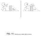
- FIG. 11shows an example of shooting over objects without looking, in a possibly-fictional game world.
- FIG. 12shows an example of illuminating behind objects without looking, in a possibly-fictional game world.
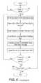
- FIG. 13shows a process flow diagram in one embodiment.
- Self-contained inertial sensora device that requires no external signal sources to be placed in the environment for measuring acceleration of a moving body along one or more axes of the six possible linear and angular axes.
- the word sensoris understood to refer to a self-contained inertial sensor.
- other devicescould be used as self-contained inertial sensors.
- a camera that compares images over timesuch as the camera used in an optical mouse
- an infrared camerathat is designed to work by tracking infrared sources or markers that have been deliberately placed in the environment is not an example of a self-contained inertial sensor.
- Accelerometera device for measuring acceleration along one or more axes at a point on a moving body.
- An accelerometeris an example of a self-contained inertial sensor.
- the devicecan be from one to tri-axial dependent upon the number of axes it measures at a given location.
- a tri-axial accelerometermeasures acceleration along three axes at the point where the accelerometer is located.
- a rigid-bodycan move independently in any of six possible degrees of freedom, three linear and three rotational. Therefore, without additional assumptions about constraints on the motion path, a single accelerometer can never be sufficient to determine the linear and angular motion of a rigid body to which it is attached.
- a single (even tri-axial) accelerometercannot even determine the motion of the rigid body it is attached to along a single degree of freedom. That is because, without additional information, there is no way to know whether the source of the accelerations it is experiencing are from linear or from angular motion of the rigid body to which it is attached.
- readings from a set of accelerometers placed at different points on a rigid body in some suitable configurationcan be processed to determine the linear and angular motion of the rigid body along all six degrees of freedom. Note that, even at rest, an accelerometer is responsive to the Earth's, or any other large enough object's, gravitational field.
- Gyroscopea device for measuring angular velocity around one or more axes at a point on a rotating object.
- a gyroscopeis an example of a self-contained inertial sensor.
- the devicecan be from one to tri-axial dependent upon the number of axes it measures at a given location.
- a tri-axial gyroscopemeasures angular velocity around three axes at the point where the gyroscope is located. While a tri-axial gyroscope is sufficient to track a rigid body's orientation over time, it provides no information with respect to linear movements of the body in space.
- Controllera movable game controller, preferably but not necessarily wireless and hand-held, with one or more self-contained motion sensors included in the controller, and providing output data to control an associated interactive application such as a computer game.
- Basic ControllerA controller, as defined above, lacking sufficient self-contained inertial sensors to track linear and angular motion in all six degrees of freedom.
- a controllerin accordance with this invention in which another controller or device containing self-contained inertial sensors has been attached to a basic controller to enhance the motion sensing capability of the basic controller.
- a self-tracking objectis an object that contains self-contained inertial sensors that produce a time series that is sufficient to track changes in position and orientation of that object.
- a composite controlleris one example of an object that could be a self-tracking object.
- FIGS. 1-3each depict one of several possible embodiments of a composite game controller in which a unitary output from the composite game controller representative of the linear and angular motion of the moving composite controller must be provided.
- a composite controlleris constructed using a dongle connection.
- the ancillary controller or housing containing the ancillary self-contained inertial sensors 103is received in the port 102 of the basic game controller 101 .
- the outputs from the self-contained inertial sensors in the dongle 103may be combined with the output of the self-contained inertial sensor in controller 101 by the data processing unit in controller 101 to provide the combined output of the whole composite controller.
- the combined sensing in all of the self-contained inertial sensors in the composite controllershould provide for motion sensing along six axes: three linearly independent axes for the sensing of the linear motion of the moving composite controller relative to the three linear axes, and three linearly independent axes for sensing the three dimensional angular movement.
- the dongle 103should include self-contained inertial sensors, that when combined with the tri-axial accelerometer in the basic controller, provide for the sensing of motion in all six degrees of freedom.
- a component 202may be banded in a fixed position and orientation to a basic controller 201 by strap 203 .
- component 202may also be an appropriate self-contained inertial sensor mounted in a housing supporting the self-contained inertial sensor.
- component 202should include enough additional self-contained inertial sensors so that the combined output of the tri-axial accelerometer and the additional sensors is sufficient to track all six degrees of freedom.
- FIG. 3another rudimentary illustration similar to FIG. 2 is shown.
- a basic controller 301is mounted on a rigid planar supporting substrate 305 .
- two additional components 302 and 303are also mounted on the substrate 305 .
- Each of the componentsprovides at least one self-contained inertial sensor.
- three game controllerswhich include self-contained inertial sensors are banded together by band 304 in fixed positions and orientation with respect to one another, the two self-contained inertial sensor containing components 302 and 303 , banded to controller 301 , need not be controllers.
- Components 302 and 303may be appropriate self-contained inertial sensors mounted in housings supporting the self-contained inertial sensors. Whether the ancillary components 302 and 303 are controllers or just the necessary self-contained inertial sensors, there must be an implementation for combining the outputs of the plurality of self-contained inertial sensors forming the composite game controller so as to provide a unitary output from the composite game controller representative of the linear and angular motion of the moving composite controller.
- each of the composite controllers depicted in FIGS. 1-3there may be provided some form of data transmission channel between the attached self-contained inertial sensor component and the basic controller.
- a conventional short range wireless RF transmissionse.g., a BluetoothTM system, may be used for example to transmit data from attached component 202 to the basic controller 201 wherein the outputs could be correlated.
- the data representative of the angular and/or linear motion of each of components 201 and 202could be wirelessly transmitted to the computer controlled game display, and correlated by the game display computer to provide the angular and linear motion of the composite controller required for playing the computer game.
- all of the self-contained inertial sensors needed to provide the sensing along six axes, needed to practice the present invention,may be built into one game controller.
- the combined self-contained inertial sensorsmust provide for sensing the total of three linear and three angular axes in order to track unconstrained motion by the user. This requirement may be satisfied in a variety of ways. In particular, any combination of accelerometers and gyroscopes providing readings on at least six distinct axes with at most three gyroscopes will be sufficient if positioned appropriately.
- the sensorsmay be placed in any known relation to one another. When less than three readings of angular velocity are present, the location and orientation of the combined self-contained inertial sensors with respect to each other is important in order to provide a feasible operative embodiment.
- each of the three embodimentsmay be considered to be a wireless composite game controller
- the resultis a system that includes a self-contained inertial sensor and programming routines that can convert acceleration and angular velocity data recorded by the device at each time t into the information sufficient to compute a new location and orientation of the device in the world frame at time t.
- a self-contained inertial sensorand programming routines that can convert acceleration and angular velocity data recorded by the device at each time t into the information sufficient to compute a new location and orientation of the device in the world frame at time t.
- Equation 2.7is a function of linear acceleration in the world frame and angular acceleration in the body frame.
- the application in the above-referenced paperassumes the use of six single-axis accelerometers, but Equation 2.7 can be easily modified to handle one or more gyroscopes instead of accelerometers by directly substituting the observed angular velocities and taking derivatives to calculate angular accelerations. Solving these equations then allows the system to track the position and orientation of a fixed point within the controller over time.
- All of the self-contained inertial sensors in any of the components in each of the embodimentsmust be positioned and oriented so as to provide a combination of self-contained inertial sensors feasible to provide outputs sufficient to compute the linear and angular motion of the moving controller as described above. While not all such sensor configurations are feasible, it has surprisingly been found that almost all of the configurations using six accelerometers turn out to be feasible. Thus, the configurations of accelerometer positions and orientations need only be grossly rather than finely adjusted in the formation of the composite game controller.
- the purpose of the present inventionis the tracking of motion on centimeter-scale accuracy on a time scale of seconds, rather than on the vehicular scale of the publication: tens of meters scale accuracy on a time scale of tens of minutes.
- the advantage of the embodiment of FIG. 1is that the dongle plug-in represents a practical embodiment of the present invention.
- a motion sensing dongle 103is plugged into the expansion port 102 of an existing motion sensing game controller 101 .
- the motion sensing game controlleris a Nintendo Wii RemoteTM
- This embodimentis commercially feasible since it relies only on one motion sensing game controller with is available to every consumer of a motion sensing enabled games console (e.g. the Nintendo Wii system).
- a new dongle containing a plurality of self-contained inertial sensorsmay then be produced at reasonable cost.
- the game controller signal that is directed from the controller to the game displaywill contain the output from the tri-axial accelerometer in the Wii Remote and the correlated output from the plurality of self-contained motion sensors in the dongle.
- the attached donglecontains enough additional self-contained inertial sensors that when combined with the motion sensing game controller's sensors (e.g., a tri-axial accelerometer), the resulting combination of sensor readings is sufficient to estimate the position and orientation of the controller over time.
- the dongle alonemay not necessarily be enough to fully specify all six variables but by selecting the number of self-contained inertial sensors and their approximate positioning in the dongle, it becomes possible through the attachment of such a dongle to a basic game controller such as a Wii remote to create a composite controller with the ability to track motion and orientation in all six dimensions even though each device has insufficient data individually.
- the donglewould include gyroscopes covering three linearly independent axes, or fewer gyroscopes with additional accelerometers to estimate angular acceleration. If a gyroscope is not available to measure angular velocity around the axis running from the tri-axial accelerometer in the basic controller to the inertial sensors in the dongle, it may be necessary to constrain the user's motion in order to get accurate state estimation, since the accelerometers will be unable to directly detect angular acceleration around this axis. The constraint is passed through by the system to inform any user of the system that they need to limit this movement of their wrist as much as they can.
- FIG. 2An alternate embodiment is shown in FIG. 2 , where multiple game controllers are combined in order to form a composite controller whose joint sensors provide for the sensing of the total of six linear/angular axes. Additional advantages may be found by including more than two controllers or using more sensors than needed to measure along the three linearly independent linear axes and three linearly independent angular axes. Note that as described in the above embodiment it may still be necessary to restrict the user's motion in some manner if the configuration of the composite controller disallows measurements along one or more of the angular axes. However, if the readings of the sensors are linearly independent the methods described in the Tan et al. publication will be sufficient to solve for all six axes even if only accelerometers are available for use.
- FIG. 2One advantage of the embodiment of FIG. 2 is that it may allow construction of the composite controller by the user from existing basic controllers. However, this method would likely then require a per-device calibration process to render the configuration known to the system. This can be implemented by having the user place the composite controller in a series of simple static poses (rather than moving the controller along precise arcs). On a flat surface, the controller is permitted to rest for a few moments with the manufacturer's faceplate of each motion sensing game controller resting on a flat surface (i.e. the y axis of each is aligned with gravity). This simple static process allows tuning of the configuration of the above referenced algorithm so that it aligns more closely with what the user has actually produced.
- the above general algorithmmay be extended to report results only at the end of one or more repeated motions, wherein each motion starts with identical initial constraints, and follows essentially the same track in time and space, with final velocities and accelerations being zero.
- Final motion track estimationmay then take as input all m solutions over time, as well as optionally all m sets of data of time series sensor readings, for linear and angular accelerations for the controller and output one final solution which is computed as a function of the m inputs.
- the algorithmmay be extended to use accelerometer-based motion recognition to constrain which repeated motions are acceptable as inputs to this final motion track estimator. Since each controller of this invention provides a motion signal, through appropriate training or calibration sessions with the proposed user, the gestures may be classified as to their provision of acceptable motion signals. Then, motions that are significantly different from the original can be identified and removed from the aggregation process described above.
- the algorithmmay be extended to inform the system when the controller has accumulated so much error that it is no longer providing reasonable tracking information.
- the algorithmmay also be extended with additional assumptions such as that the computed velocities are not permitted to exceed human limitations at any point in time t, and along any axis.
- FIG. 5is a simple diagrammatic illustration of what has been described with respect to the apparatus of FIGS. 1-4 .
- Computer controlled interactive game display 500has game action 501 which is controlled by a game controller 503 which may preferably be a composite controller in accordance with the present invention carried along some path 506 , which has a linear component 504 and an angular component 505 , by a player's moving hand 502 .
- the programming in the computer controlled display 500 and in the handheld controller 503assumes that the player holds the controller in some starting position and then as the player moves the controller the programming is able to estimate the relative position and orientation of the controller 503 reliably for several seconds. During that time, a game 500 is able to draw 501 a representation of the controller's state.
- Known techniquessuch as inverse kinematics, allow the state of the controller to drive an animation in a game. For example, a game character could swing a virtual sword in a manner that is similar to the way the player swung the physical controller.
- the location of the boundary of the gamei.e. the limits of the controller 503 movement with respect to the game display 500 , is arbitrary and domain-dependent.
- FIG. 6there will be described a generalized flowchart of the programming in the operation of the invention using a game controller for a computer controlled game display, as has been described with respect to FIG. 5 .
- An initial determinationis made as to if the user has started the controller motion, step 601 .
- initial state of the controllerthe following constraints are suggested: initial velocities and accelerations are zero. If the initial determination of motion is “Yes”, then the readings from all the sensors in the controller must be obtained. In the case of a composite controller, this includes all sensor readings from the basic controller as well as all reading from any sensors associated with other components that comprise the composite controller. Typically, the sensor values are read at some suitable high frequency and, at an appropriate point consistent with the computer game being played, the data from the sensor readings is output to the computer controlled game display via the previously described short range RF transmission, step 602 .
- step 603in which the angular motion is extracted from the sensor readings. This step will depend on the particular configuration of sensors used. For example, if three gyroscopes are used, then the gyroscopes will provide readings of angular velocity which can be integrated once to obtain the relative angular motion, i.e. the change in orientation. If accelerometers are used instead, then the readings will provide angular acceleration which can be integrated twice to obtain the relative angular motion.
- step 603will perform the appropriate action of integrating once for readings from gyroscopes and twice for readings from accelerometers.
- the change in orientation calculated in step 603is then used in step 604 to update the previous orientation estimate by adding in the change in orientation.
- the sensor readings not used in calculating the angular motionare then extracted from the sensor readings data, step 605 .
- the remaining sensor readingswill be from accelerometers and the estimate of the angular motion from step 603 can be factored out of those accelerometer readings, step 606 , to leave the accelerations due to linear motion along all three linear axes, i.e.
- step 607the position of the controller can be updated, step 607 , using the estimated change in position calculated in step 606 .
- step 608a determination is made as to whether the movement is being continued. If Yes, the process is returned to step 602 , and movement tracking is continued. If No, a further determination is made as to whether the game is over, step 609 . If Yes, the game is exited. If No, the process is branched back to step 601 wherein the player's next controller movement is awaited.
- FIG. 7there will be described an overview of one way of using the software elements.
- the left hand sideshows the situation at a first time 706 .
- the right hand sideshows the situation at a second time 707 .
- a game player 702is holding a self-tracking object 703 .
- the output from the self-tracking object 703is being communicated to a game console 704 , wirelessly or by some other technique.
- the game console 704operates in conjunction with a game.
- the gameis presenting a depiction of a game world (such as a made-up, fictional, world) on a display or other presentation device 720 .
- the playerperforms a gesture or other motion 711 with the self-tracking object 703 .
- the motion 711includes a translational component 712 and a rotational component 713 , as a result of which the device is moved from the first configuration 708 at the first time period 706 to a second configuration 714 at the second time period 707 .
- the self-tracking object 703In response to the motion 711 , the self-tracking object 703 generates one or more time series of data, those one or more time series data being descriptive of the motion 711 .
- Software elements 705being executed on the game console 704 , or being executed on another device and accessible by the game console 704 , interpret at least some of the time series of data generated by the self-tracking object 703 in response to the motion 711 , and cause the presentation device 720 to display a corresponding animation of an object corresponding to the self-tracking object 703 (such as some fictional character in the game world) moving from a first configuration 715 to a second configuration 716 .
- those software elements 705use methods as described herein to create a more faithful corresponding animation of that motion than would otherwise be possible.
- FIG. 8there will be described a backfitting algorithm, as used in one embodiment, applied to a self-tracking object.
- the motiontakes place in three dimensions, with three degrees of translational freedom and three additional degrees of rotational freedom.
- the description belowrelates to a 2-dimensional motion 811 .
- the description below of the 2-dimensional caseis more than adequate to illustrate how the method is applied to a 3-dimensional motion 811 . Accordingly, those skilled in the art would easily understand from a description of the method with respect to a 2-dimensional motion 811 , how to apply the same method with respect to a 3-dimensional motion 811 .
- a motion 811starts with a self-tracking object, such as the motion sensitive device 703 shown in FIG. 7 , in some first configuration in which the position 801 and the orientation 802 are known, or at the least, assumed to be known. Methods for inferring the initial configuration of the object are described in greater detail below.
- the orientation 802 of the self-tracking objectis inferred from accelerometer readings that, during momentary periods of quiescence, indicate the direction of gravity relative to the self-tracking object.
- the software elements 705determine, in response to sensor readings from accelerometers and gyroscopes, whether a period of quiescence is taking place.
- the originis set to the location of the self-tracking object.
- information from a direct pointing devicemay be used to infer information about the initial configuration.
- the self-tracking objectmight include a laser pointer which the player might orient by directing that laser pointer at the presentation device 820 , or some other device whose location is known to the software elements 705 .
- the self-tracking objectmight include a laser pointer which the player might orient by directing that laser pointer at the presentation device 820 , or some other device whose location is known to the software elements 705 .
- sensors, assumptions, or both sensors and assumptionsmay be used to obtain information regarding a starting configuration of the self-tracking object.
- the software elements 705integrate and combine gyroscope and accelerometer readings to provide estimates of changes in the self-tracking object's time-varying configuration.
- orientation( t+dt )orientation( t )+Gyro( t )* dt
- velocity( t+dt )velocity( t )+(orientation( t )*( Acc ( t ) ⁇ (Centripetal Accelerations from rotation at time t )) ⁇ Gravity)* dt
- position( t+dt )position( t )+velocity( t+dt )* dt
- Gyro(t)includes three orthogonal readings of angular velocity at time t. Multiplying by dt, the time elapsed since the previous readings, gives the angular change around each axis since the previous readings. This change can be applied to the previous estimate of orientation. Embodiments for making these computations depend on the form in which the orientation information is stored. In the games industry, quaternions are commonly used for this purpose, in which case the angular change from the Gyro(t)*dt term can be converted to a quaternion rotation and added using quaternion arithmetic.
- Acc(t)includes three orthogonal readings of acceleration at time t in the frame of reference of the object. If the accelerometers are not physically co-located with the gyroscopes, the computation first subtracts any accelerations resulting from the accelerometers rotating around the location of the gyroscopes. For example, if the accelerometers are displaced along the z-axis of the object, the following adjustments would need to be made to the accelerometer readings: Since Acc(t) and Gyro(t) are vectors [0], [1], and [2], and are used to refer to their individual scalar components.
- the adjusted accelerometer readingsare translated from the object frame to the world frame using the current orientation of the object. Acceleration due to gravity (approximately 9.8 m/s/s on planet Earth's surface) is subtracted. The changes in each of the three dimensions of the object position can be found by multiplying by dt*dt.
- the software elements 705can generate estimates of position and orientation, as indicated by the dotted line 803 . Due to the accumulation of errors in sensor readings, e.g., caused by noise, limited precision, or other factors, or possibly due to errors in transmission of the time series data, the actual position and orientation of the self-tracking object are likely to generate a set of estimates of position and orientation 805 that differ at least somewhat from reality. Over time the difference can become sufficient to be relevant to operation of the game console 704 and the game. For example, the difference might become large enough that an animation generated by coupling the inferred position and orientation estimates might appear more and more unrealistic to the player as time progresses.
- the software elements 705receive additional information regarding position and orientation of the motion sensitive object 703 that becomes available at an identifiable time, with the effect that software elements 705 are able to determine a new instantaneous position 806 a and orientation 806 b .
- thiscan happen if the player stops moving the motion sensitive device 703 , with the effect that an identifiable period of quiescence is entered.
- the software elements 705might receive readings from other sensors, such as a pointing device as described above, with the effect that at least some subset of the new instantaneous position 806 a and orientation 806 b can be more precisely inferred at that time.
- the informationcan be used for more than just obtaining more reliable estimates at that moment in time.
- the informationcan be used to infer something about the errors over at least some portion of the recent history of sensor readings.
- a new trajectorycan be calculated, as shown as the solid line 804 in FIG. 8 .
- the new trajectory 804may still not be a perfect reflection of the actual trajectory of the self-tracking object, but the inventors have found it to be a more accurate and useful one than just the original estimate. In particular, it can be used to drive an animation that, although delayed, appears as a more accurate rendition to the player of the motion 811 just performed.
- computation of the re-estimated trajectoryincludes the following elements and steps:
- a first categoryincludes errors that are essentially random in their effect on the sensors at different times. Such errors might be in response to noise in reporting of the sensor readings, truncation errors in reporting of the sensor readings due to limited precision, and the like. For one example, if gyroscope readings are reported as 8-bit values, this would have the effect of essentially random errors—the differences between the true values and the values that are rounded to this limited precision.
- a second categoryincludes errors that are systematic, i.e., when a particular sensor has its data affected in a substantially consistent way over time. Such errors might be in response to miscalibration of that sensor (e.g., the sensor data reported for a true value of zero might be miscalibrated to a finite nonzero value).
- the predicted orientationcan be forced to match the target orientation by adjusting each Gyro(t 1 ) by (tgtOrient ⁇ orientation[t k ])/(t k ⁇ t 0 )*(t i ⁇ t i-1 ).
- the computationallocates these adjustments to the two sources of error described above. Viewing the category of random errors as a random walk of k steps, there should be a typical deviation of sqrt(k)*err ⁇ sensor>, where err ⁇ sensor> is the typical error for that sensor on an individual reading. This value can be determined by experimental analysis. The remaining error, if any, can be assumed to be an offset error on the gyroscopes and applied to future readings. In one embodiment, it might be desirable to limit the maximum corrections that are applied to attribute any residual corrections to further-unknown factors.
- the computationapplies a similar procedure to adjust the accelerometer readings using the new estimates of orientation during the updating of position.
- the procedure for positionis somewhat more complicated since the adjustments applied to accelerometer readings will have different effects on the final position depending on the orientation of the sensor at the time.
- the computationassumes that the new adjusted orientations and centripetal accelerations are correct.
- the computationcan then calculate the effect of each of the three accelerometer readings on each of the three components of position for each step, using equations (2) and (3) above.
- ⁇is a vector indicating the effect that each component of Acc(t i ) has on component j of velocity given the orientation(t i ).
- This equationgoverns how changes in the Acc readings will affect the final position.
- the computationsolves to find the minimum adjustments to make to Acc in order to match the target position. In response to these adjustments, the computation can divide them between noise and offset errors, using the method described above.
- Line 807shows a second position and orientation path generated by the software elements 805 using a second set of estimation parameters, after incorporating new information as described above, and after re-estimating the position and orientation path shown by line 808 .
- This processcan be applied repeatedly and iteratively, with the effect that the software elements 705 might accurately determine relatively longer sequences of faithful tracking of the motion 811 .
- the computation described aboveuses information about the target configuration to adjust the estimated trajectory and sensor errors.
- the computationmay use information about target velocities.
- the computationuses a symmetric procedure obtained by substituting equation (11) below for equation (10) above.
- FIG. 9there follows a description of a data flow diagram 900 of information flow in a game control system.
- a self-tracking object 917provides a set of raw sensor readings 902 , which are received from the self-tracking object 917 by device driver 901 .
- the device driver 901applies hardware calibration steps to produce a set of calibrated sensor readings 908 .
- Techniques for hardware calibrationare known to those skilled in the art and include, for example, (a) modifying the raw sensor readings 902 according to known or calculated temperature variations, and (b) compensating for errors that may have been introduced in the manufacturing process of the self-tracking object 917 . Manufacturing errors might be detected in a calibration step performed in the factory when the self-tracking object 917 is manufactured.
- the game 911will formulate assumptions 910 about the initial configuration of the self-tracking object. These assumptions can include assumptions that the software elements 705 should make about the initial configuration of the object. For example, the game 911 might supply one or more components of the initial position or orientation of the object.
- a configuration initiator 909receives those assumptions 910 supplied by the game 911 . From those assumptions 910 , the configuration initiator 909 determines an initial configuration that will be used by the tracker 918 .
- the game 911provides an initial position for the object and an assumed value for the rotation of the object around the axis corresponding to gravity, here labeled the z-axis.
- the other two components of the orientationcan be computed by the configuration initiator 909 in response to readings from the inertial sensors. This computation can be performed when the object is at rest.
- the configuration initiator 909can use information from the sensors to infer whether the device is currently in motion. For example, if the self-tracking object 917 can be assumed or detected to be still, gravity readings can be used to infer orientation information. When the device is relatively motionless, the gyroscope readings will all be close to zero and the acceleration reported by the sensors should be due almost entirely to gravity. In such cases, the accelerometer readings should be consistent over time and have a norm approximating an acceleration of one gravity (approximately 9.8 m/s/s). When these conditions are substantially met, the configuration initiator 909 determines that the object is substantially at rest.
- the configuration initiator 909can determine two components of orientation by finding the necessary rotations in the world frame in order to align the accelerometer readings entirely along the z-axis. In one embodiment, the configuration initiator 909 determines a set of rotations to align the axis with the largest accelerometer reading. This computation might be performed as shown in the following pseudo-code:
- the configuration initiator 909sets the remaining component using input from the game. In one embodiment, the configuration initiator 909 presumes the rotation around the z-axis is zero.
- the configuration initiator 909might use these other sensor readings to determine information about the initial configuration.
- the tracker 918assumes that the current configuration is the initial configuration 912 . As time passes, the tracker 918 determines the current configuration by applying changes to the initial configuration in response to calibrated sensor readings 908 .
- the sensors in the self-tracking object 917include gyroscopes and accelerometers sufficient to track changes in position and orientation of the self-tracking object 917 .
- the software elements 705integrate and combine gyroscope and accelerometer readings according to known principles.
- the tracker 918applies constraints to the calibrated sensor readings 908 . These constraints include clamping the readings to allowable ranges, clamping values calculated from the readings to known ranges, introducing a drag term, or requiring a minimum impulse to act as a threshold to avoid misinterpreting hand tremors as significant motion.
- the tracker 918uses known techniques, from the art of inertial guidance and related fields, to generate a configuration estimate 905 .
- the configuration estimateis sent to a corrector 907 that adjusts the estimate to produce a corrected estimate 916 .
- the correctionsare dynamically calculated using the backfitting algorithm described above, stored 903 and periodically updated 906 . Examples, not intended to be limiting in any way, of corrections include:
- the tracker 918may use logical assumptions about motions of that human being to determine whether any particular pose, or sequence of poses, is likely or unlikely. For example, if the human being is—by the nature of the application—assumed likely to be standing in a relatively fixed location, any reported or estimated position of the self-tracking object 917 too far from that relatively fixed location may be adjusted in response to that distance. This has the effect that any reported or estimated position of the self-tracking object 917 would be substantially constrained to remain within a box or sphere surrounding the human being's initial position and limited by that human being's typical physical reach.
- the tracker 918might, from time to time, detect the angular orientation of the self-tracking object 917 with respect to gravity, i.e., from what angle from “up” or “down” the self-tracking object 917 is instantaneously pointing. For example, if the self-tracking object 917 enters a quiescent state, the angular orientation of the self-tracking object 917 can be adjusted accordingly.
- the tracker 918might, from time to time, assume that the self-tracking object 917 is in a period of likely quiescence, such as for example when the game indicates that there is nothing for the game player to do, and the game player is thus likely to not be moving the self-tracking object 917 . If the tracker 918 is able to detect a period of likely quiescence, the relative velocity and angular velocity of the self-tracking object 917 can be determined, and parameters describing the position and orientation of the self-tracking object 917 can be adjusted accordingly.
- the tracker 918might, from time to time, receive data from the user, such as a game player, indicating information the user supplies that can be used to aid in determining the position and orientation of the self-tracking object 917 .
- the tracker 918might use the timing of that button-press to restrict the set of possible positions or orientations of the self-tracking object 917 , e.g, to those in which the self-tracking object 917 is oriented so that the simulated gun is actually pointed toward a target.
- the tracker 918might use that text data (or use the fact that such text data is being entered) to restrict the set of possible positions or orientations of the self-tracking object 917 , with the effect that the tracker 918 might adjust its determination of position and orientation of the self-tracking object 917 accordingly.
- the tracker 918might, from time to time, receive input values from additional sensors, such as for example a light pen, infrared remote sensor, or other indicator of the orientation of the self-tracking object 917 .
- the tracker 918might use those values from additional sensors to restrict the set of possible positions or orientations of the self-tracking object 917 , with the effect that the tracker 918 might adjust its determination of position and orientation of the self-tracking object 917 accordingly.
- the corrected estimate 915can then be further corrected based on in-game constraints and assumptions. Examples, not intended to be limiting in any way, of in-game corrections include:
- the tracker 918might determine constraints on the position and orientation of the self-tracking object 917 according to restrictions it believes on the set of possible final configurations of the self-tracking object 917 at the end of a motion. For example, if the end of a motion (or any part of a motion) would place the self-tracking object 917 in the same spatial location as the user's head or body, or in the same spatial location as a wall or the game controller itself, the tracker 918 might restrict the set of possible positions and orientations of the self-tracking object 917 to exclude that possibility, and adjust its determination of the position and orientation of the self-tracking object 917 accordingly.
- the tracker 918might apply game constraints to the set of possible motions of the self-tracking device 917 , such as if the self-tracking device 917 is being used by the game player to emulate a particular type of object (e.g., to use a sword in a fantasy game, or to use a golf club in a sports game).
- the tracker 918might therefore restrict the set of possible motions, and therefore changes in relative position and orientation of the self-tracking device 917 , accordingly.
- the tracker 918would be able to restrict the possible motions of that simulated sword so that it cannot pass through, or terminate its motion in, certain types of objects in the game word, e.g., solid walls or other swords.
- the tracker 918would be able to restrict the possible motions of that simulated baseball bat so that it remains in or near a strike zone in the baseball game. This would have the effects of (a) limiting the scope of possible animation, thus simplifying the task of performing that animation, (b) detecting relatively larger errors in tracking of the self-tracking object 917 , and (c) detecting anomalous behavior by the human being, such as if that human being decides to walk away from the simulated batting region.
- An application using the self-tracking device 917might involve use of motion recognition signals, such as for example as described in detail in U.S. application Ser. No. 11/486,997, “Generating Motion Recognizers for Arbitrary Motions”.
- the motion recognition signalclassifies the movement of the self-tracking device 917 into one (or possibly more than one) of a set of preselected classes of motions.
- the tracker 918might use a motion recognizer that classifies motions by the self-tracking device 917 into known gestures used in those environments, e.g., frying, flipping, chopping, pounding, and the like.
- a motion recognizerthat classifies motions by the self-tracking device 917 into known gestures used in those environments, e.g., frying, flipping, chopping, pounding, and the like.
- An arbitrary motion by the human being holding the self-tracking device 917would be classified into one or more of these known gestures, with the effect of providing a motion recognition signal assigning the motion to one or more of those known gestures.
- the motion recognition signalmight (a) uniquely classify the motion as a particular gesture, (b) classify the motion as one of a set of possible gestures, (c) associate the motion with a probability or other score of being each one of those possible gestures, and the like.
- the tracker 918can use the knowledge it obtains from the motion recognition signal—assignment of the motion to a particular class of gestures—to restrict the set of possible estimates of position and orientation of the self-tracking device 917 to those consistent with the motion recognition signal.
- any sensor readings or time series data received from the self-tracking device 917 inconsistent with that gesturee.g., motions more likely to be associated with chopping vegetables or pounding meat
- the tracker 918might then dampen use of those sensor readings or time series data, with the effect of improved, or at least more consistent, estimation of position and orientation of the self-tracking device 917 .
- the inconsistent motionsresulted from unconscious or unintended movement by the human being holding the self-tracking device 917 , the tracker 918 would be able to provide that human being with a perception of improved tracking.
- the motion recognition signalmight provide additional information relating the motion to particular gestures, such as possibly (a) an evaluation of a measure of distance between that motion and each classified gesture, or (b) an evaluation of a measure of distance between that motion and particular prototypes within particular classes of gesture.
- the tracker 918might use the ambiguity between these possibilities to choose to be less aggressive about dampening use of those sensor readings or time series data that are ambiguous.
- a canonical animationmight be associated with each particular gesture, with the effect that the animation actually presented in response to a particular motion might be a blend of the estimated actual motion of the self-tracking device 917 and of the canonical animation assigned to the detected-and-classified gesture. In some applications, this would allow the tracker 917 to perform a “snap to fit” function, i.e., to present the actual motion in (one of) the way(s) the gesture should ideally be performed, rather than the approximation actually performed by the human being.
- the presented animationmay be a weighted blend of canonical animations associated with those more than one classes of gesture the motion was detected-and-classified to be. Relative weights of that blend might be responsive to the measures of distance to each class, to the probabilities associated with each class, and the like.
- a canonical animationmight be associated with each particular prototype within a particular gesture class.
- the animation actually presented in response to a particular motionmight be (a) a blend of the canonical animations associated with those prototype gestures, (b) snapped to fit a selected one of the canonical animations associated with those prototype gestures, (c) a blend of the canonical animations associated with one or more of those prototype gestures and the actual motion of the self-tracking device 917 .
- weights associated with each possibility for the blendmight be responsive to measures as described above.
- the tracker 918might from time to time, receive DPD (direct pointing device) readings, such as for example determining that the self-tracking object 917 is aligned in a known orientation from alignment of the self-tracking object 917 with a set of LEDs or other electromagnetic or sonic alignment elements.
- the tracker 918might use those DPD readings to restrict the set of possible positions or orientations of the self-tracking object 917 , with the effect that the tracker 918 might adjust its determination of position and orientation of the self-tracking object 917 accordingly.
- the tracker 918might, from time to time, presume that the self-tracking object 917 is no longer moving, such as for example when the game controller indicates that there is no action for the user to take.
- the tracker 918might use that assumption to restrict the set of possible positions or orientations of the self-tracking object 917 , with the effect that the tracker 918 might adjust its determination of position and orientation of the self-tracking object 917 accordingly.
- the game corrected estimate 912is communicated back to the game where it is typically used to drive an animation that is intended to correspond to the motion of a game element corresponding to the self-tracking object 917 .
- a game elementis a sword (in a fantasy game), or a golf club (in a sports game)
- a presentationwould be made of that game element moving in accordance with the way the user moved the self-tracking device 917 .
- the tracker 918assumes a one-to-one mapping of the self-tracking object 917 to motion of a simulated object in a virtual environment, the latter being presented to a user using animation.
- the tracker 918assumes a one-to-one mapping of the self-tracking object 917 to motion of a simulated object in a virtual environment, the latter being presented to a user using animation.
- other and further mappingsare possible, as described below.
- the virtual environmentmight determine a force or other motive power in that virtual environment, in response to changes in position or orientation of the self-tracking object 917 .
- a sharp change in position or orientation of the self-tracking object 917might be interpreted as a directive to impart a throwing or maneuvering force on an object in that virtual environment.
- the virtual environmentwould (a) determine an amount of force to apply, (b) in response thereto, determine a set of changes in position or orientation of that object in that virtual environment, and (c) in response thereto, determine an animation of that virtual environment including that object.
- Examples of such action in response to changes in position or orientation of the self-tracking object 917include:
- the self-tracking object 917might be used to simulate a throwable object—e.g., a baseball—in the virtual environment, with changes in position or orientation of the self-tracking object 917 being used to determine how hard and in what direction that object is thrown (e.g., the user might pretend to throw a baseball using the self-tracking object 917 to simulate the baseball, being careful of course not to actually throw the self-tracking object 917 at the game controller, unless that self-tracking object 917 is padded or otherwise secured to allow for actual throwing);
- a throwable objecte.g., a baseball
- changes in position or orientation of the self-tracking object 917being used to determine how hard and in what direction that object is thrown (e.g., the user might pretend to throw a baseball using the self-tracking object 917 to simulate the baseball, being careful of course not to actually throw the self-tracking object 917 at the game controller, unless that self-tracking object 917 is padded or otherwise secured to allow for actual throwing);
- the self-tracking object 917might be used to simulate a tool for striking or throwing—e.g., a baseball bat—in the virtual environment, with changes in position or orientation of the self-tracking object 917 being used to determine a force or other motive power in that virtual environment, with that force being used to determine how hard and in what direction an object is struck (e.g., the user might pretend to hit a baseball with a baseball bat using the self-tracking object 917 to simulate the baseball bat;
- a tool for striking or throwinge.g., a baseball bat
- changes in position or orientation of the self-tracking object 917being used to determine a force or other motive power in that virtual environment, with that force being used to determine how hard and in what direction an object is struck (e.g., the user might pretend to hit a baseball with a baseball bat using the self-tracking object 917 to simulate the baseball bat;
- the self-tracking object 917might be used to simulate a tool in the virtual environment, such as a light switch or a trigger of a gun, with the effect that changes in position or orientation of the self-tracking object 917 would be interpreted by that virtual environment to indicate that sufficient force had been applied in that virtual environment to switch on a light or fire a gun.
- a viewpoint(such as a viewpoint of a user or of a camera) in the virtual environment might be responsive to changes in position or orientation of the self-tracking object 917 .
- the usermay be allowed to indicate a direction or to select objects in a virtual environment (such as a virtual reality depiction of a possibly-fictional 3D environment). The user might be provided with this capability even in circumstances where the user's view is otherwise obstructed in the virtual reality depiction.
- the usermight be physically holding self-tracking object 917 , with the virtual environment simulating an object corresponding to that object.
- the simulated object, or “CVD”could be pretty much any object, such as a gun, a whip, a pointing device (e.g., a laser pointer).
- CVDcorresponding virtual device
- a line segment(or another path) is computed, coupled to the CVD and extending into a region of the virtual environment near the CVD.
- the computationis based on changes in one or more of position or orientation of the self-tracking object 917 , possibly combined with additional information from the virtual environment. This could include setting the direction of the line segment or other path in direct correspondence to the change in orientation of the self-tracking object 917 .
- the line segmentmight be straight, such as for a laser pointer, or nearly so, such as for a gun (taking into account gravity and windage), or might be deliberately curved, such as for a whip.
- the computed line segmentthus represents a line segment desired by the user. If the computed line segment intersects a object or construct (e.g., a non-physical “object” such as a surface or region) in the virtual environment, e.g., touching a virtual object, plane, or character, the virtual environment determines that the user is deliberately selecting or otherwise indicating that intersected object or construct.
- a object or constructe.g., a non-physical “object” such as a surface or region
- FIG. 10shows a three-dimensional virtual environment 1000 including various objects 1001 and 1002 .
- a CVD 1005is a representation of the self-tracking object 917 in the virtual environment 1000 .
- objects and constructscan be selected using some line segment (or “ray”) 1006 .
- the CVD 1004 and line segment's new location 1003allow the user to select a new object 1002 . This allows game players in virtual worlds to select objects that are otherwise obscured along their normal viewing plane.
- Examples of using this methodcould include a game player holding a self-tracking object 917 as a controller that corresponds, in a virtual environment, to a gun, flashlight, or whip. The player can then move the controller around to indicate the direction of the gun, flashlight, or flexible cable. Changes in the position or orientation of the self-tracking object 917 could be applied to the corresponding CVD.
- the self-tracking object 917corresponds in the virtual world to a gun (or another projectile device, such as a bow)
- a game playermight be taking cover in a virtual environment behind a low wall, as shown on the left-hand side of FIG. 11 .
- the game playerwould lift the self-tracking object 917 , causing the CVD gun to move within the virtual environment, and point the CVD gun at an angle down into the area behind the wall, without the game player changing their vantage point, as shown on the right-hand side of FIG. 11 .
- the game playerwould be provided with the capability for indicating any angle for the CVD flashlight into the screen, and would not be restricted to only those origin points above the viewing plane.
- FIG. 12on the left-hand side, shows an object in the virtual environment obscuring the game player's view deeper into the room.
- the game playerwould move the self-tracking object 917 to cause the CVD flashlight to illuminate regions behind the obstructing object without requiring any change in vantage point within the virtual environment, as shown on the right-hand side of FIG. 12 .
- the game playerwould be provided with the capability of “reaching around” an obstructing object in the virtual environment, e.g., to thread the cable through a pipe that would otherwise be unseen by the game player.
- the technique described aboveallows a game player to indicate direction within a virtual environment using all six degrees of freedom of position and orientation of the self-tracking object 917 . This has substantial advantages over known methods of indicating direction.
- the processwill typically repeat in a game as the player moves the controller around in response to stimuli and instructions from the game.
- the gamestarts and there is some initial period of setup.
- This setupmay include memory allocation and any other well-known steps.
- the gamethen waits for a signal that a button has been pressed on the self-tracking object. Pressing a button is only one example of a starting criteria for tracking to begin. Alternatively the game may signal the start based on internal state and communicate suitable instructions to the player.
- the self-tracking objectmay still not yet be ready to being tracking. For example, in one embodiment, a brief period of quiescence might be required before tracking can begin so the player still needs to hold still for a while after pressing the button. Alternatively, additional sensor readings may be required in order to determine a initial configuration. For example, the player might initially point at a direct pointing device.
- the initial configurationis setup from any information available to the tracker 918 .
- the tracker 918then iterates the process described above, in which the tracker 918 ( a ) performs the following:
- the tracker 918receives time series data from the self-tracking device 917 .
- the tracker 918makes estimates of the position and orientation of the self-tracking device 917 in response to those time series data.
- the tracker 918receives information allowing it to make a better estimate the position and orientation of the self-tracking device 917 .
- the tracker 918updates its estimates for the most recent set of historical position and orientation of the self-tracking device 917 .
- this processis repeatedly iterated until the tracker 918 receives a signal that tracking can cease. Termination signals could be time based, game event based, or button based.
- the tracker 918continues to make estimates of the position and orientation of the self-tracking device 917 , until the game finishes.
- sensor data provided by the controllers of this inventionmay be analyzed and compared to a provided standard data output that corresponds to specific animations.
- the animation to which the sensor data is the best matchis then selected and played. It is also possible to modify the selected animation based on the degree of correspondence between the sensor data and the best match. For example, if the sensor data indicates that the motion is a faster version of some provided animation, then the animation can be played at a correspondingly faster speed.
- Most currently available game controllersdo not contain the required six axial accelerometer configuration to fully determine the player's actual motion in a gyroscope-free controller.
- some modern game controllersthere are only three approximately co-located accelerometers or a single tri-axial accelerometer.
- Using such controllers to render an animation on the screen that corresponds to a player's motionrequires strong assumptions to be made about the player's intended motion. In some cases, this requirement can be mitigated with known techniques.
- some modern game controllerscontain an infrared sensor that when pointing at some direct point device (DPD) provides additional information that can be used to determine more information about player movement.
- DPDdirect point device
- the player's movementhas to be restricted to a narrow range of motions that keep the DPD within range of the infrared sensor.
- the concepts of the present inventionmay be extended to add more sensors into the system.
- the above described general algorithmmay be extended to such configurations. For example, there could be three motion sensing game controllers have nine accelerometer sensing axes, not just six. The sensing of the three additional axes could provide feedback to be applied to the general algorithm.
- the general algorithmcould be applied to shorten time. There may be many potential competing errors in the system. The samples/sec. may be reduced to limit sensitivity over time, while trading off against integration errors. This in part is based on time scale in which a human movement occurs. Based on the concept of the present invention, a cube with accelerometers placed in a certain configuration on each face can reliably track position and orientation of the controller for longer periods of time. Such a cube could be mounted on a controller, e.g., via an appropriate dongle connection.
- 1-3could include estimates of: the self-contained inertial sensor reading when the device is at rest; the upper and lower range of the self-contained inertial sensor; the sensitivity of the self-contained inertial sensor; how the sensitivity varies with time, temperature, and other conditions; the relative positions of the individual self-contained inertial sensors within the controller; the physical size of the controller; the distance between each controller; the relative orientation of each controller from one another; the relative position of the center of mass of each controller.
Landscapes
- Engineering & Computer Science (AREA)
- Multimedia (AREA)
- Human Computer Interaction (AREA)
- Theoretical Computer Science (AREA)
- General Engineering & Computer Science (AREA)
- Physics & Mathematics (AREA)
- General Physics & Mathematics (AREA)
- Health & Medical Sciences (AREA)
- Life Sciences & Earth Sciences (AREA)
- Biophysics (AREA)
- Cardiology (AREA)
- General Health & Medical Sciences (AREA)
- Heart & Thoracic Surgery (AREA)
- User Interface Of Digital Computer (AREA)
- Position Input By Displaying (AREA)
Abstract
Description
orientation(t+dt)=orientation(t)+Gyro(t)*dt (1)
velocity(t+dt)=velocity(t)+(orientation(t)*(Acc(t)−(Centripetal Accelerations from rotation at timet))−Gravity)*dt; (2)
position(t+dt)=position(t)+velocity(t+dt)*dt (3)
IncreaseAcc(t+dt) byAA*zOffset−(Gyro(t+dt)*Gyro(t+dt))*zOffset (4)
IncreaseAcc(t+dt) by −AA*zOffset−(Gyro(t+dt)*Gyro(t+dt))*zOffset (5)
IncreaseAcc(t+dt) by (Gyro(t+dt)2+Gyro(t+dt)2)*zOffset (6)
where
AA=(Gyro(t+dt)−Gyro(t))/dt (7)
AA=(Gyro(t+dt)−Gyro(t))/dt (8)
orientation(to)+Σi=1 to kGyro(ti)*(ti−ti-1) (9)
position(tk)[j]=position(t0)[j]+velocity(t0)[j]*(tk−t0)+Σi=1 to kØ*Acc(ti)*(ti−ti-1)*(ti−ti) (10)
velocity(tk)[j]=velocity(t0)[j]+Σi=1Ø*Acc(ti)*(ti−ti-1) (11)
| if largestAxis is Positive X | (12) |
| largeRot[Z] = M_PI/2; largeRot[X] = M_PI/2; | |
| else if largestAxis is Negative X | |
| largeRot[Z] = −M_PI/2; largeRo[0]t = M_PI/2; | |
| if largestAxis is Positive Y | (13) |
| largeRot[Z] = M_PI; largeRot[0] = M_PI/2; | |
| else if largestAxis is Negative Y | |
| largeRot[Z] = 0; largeRot[0] = M_PI/2; | |
| if largestAxis is Positive Z | (14) |
| largeRot[Z] = 0; largeRot[0] = M_PI; | |
| else if largestAxis is Negative Z | |
| largeRot[Z] = 0; largeRot[0] = 0; | |
| set initialOrientation using largeRot; | (15) |
| gravReading = initialOrientation*Acc; | (16) |
| rotX = −atan(gravReading(Y)/tmpReadings(Z) ); | |
| adjust initialOrientation by rotating an additional rotX around | (17) |
| the X axis | |
| gravReading = initialOrientation*Acc; | (18) |
| rotY = atan(tmpReadings(X)/tmpReadings(Z) ); | |
| adjust initialOrientation by rotating an additional rotY around | (19) |
| the Y axis | |
- The
tracker 918 might partially determine constraints on motion of the self-trackingobject 917 by presuming that the self-trackingobject 917 follows motions restricted by a mechanical model of a human figure. For example, if it is known that a position estimate would violate an assumption about limb length, such as a motion that would only occur if the game player's arm would bend unrealistically, theestimate 905 can be corrected accordingly. - In one embodiment, the
tracker 918 might make estimates for position and orientation of a model of the figure of the human being as that person is moving the self-trackingobject 917. For example, thetracker 918 might determine an estimate of the position and orientation of the arm, shoulder, and hand holding the controller of that human figure, at each time step in a periodic (or otherwise defined) time sequence. This would include estimating angles for each relevant joint of the human body as well as, possibly, extensions of musculature, collectively referred to herein as “poses”, using, e.g., known techniques for inverse kinematics such as those described in R. FEATHERSTONE, ROBOT DYNAMICS ALGORITHMS. - In such embodiments, the
tracker 918 would examine each such estimated pose and adjust its estimates for the likelihood of the estimated pose (in addition to or in lieu of adjusting its estimates for the likelihood of the estimated position and orientation of the self-tracking object917). Likelihood of any particular estimated pose might be determined using (a) information about human physiology, e.g., how elbows, shoulders, wrists, and the like, are able to rotate, and (b) information about the particular application in which the self-trackingobject 917 is being used as a controller. - For example, in embodiments in which the self-tracking
object 917 is being used to simulate a baseball bat, e.g., a sports game, thetracker 918 can evaluate the likelihood of particular baseball-bat-swinging motions, and assign poses relating to those swinging motions in response to their likelihood if performed by a baseball-bat-swinging player. This would have the effect that poses in which the baseball-bat-swinging player contacts an (imaginary) baseball have greater likelihood than otherwise. Moreover, thetracker 918 can take advantage of one or more simplifying assumptions, e.g., that the baseball-bat-swinging player is standing relatively still and upright while swinging the self-trackingobject 917 with a two-handed grip. - In such embodiments, when the
tracker 918 encounters an estimated pose (or sequence of poses) that it deems unlikely—either given human physiology or the nature of the information about the particular application in which the self-trackingobject 917 is being used as a controller—thetracker 918 can (a) adjust that estimated pose or sequence of poses to one that is more likely, and (b) re-estimate the motion of the self-trackingobject 917, and consequentially the pose or sequence of poses, to conform with that adjustment.
- The
Claims (17)
Priority Applications (1)
| Application Number | Priority Date | Filing Date | Title |
|---|---|---|---|
| US14/055,594US9261968B2 (en) | 2006-07-14 | 2013-10-16 | Methods and systems for dynamic calibration of movable game controllers |
Applications Claiming Priority (5)
| Application Number | Priority Date | Filing Date | Title |
|---|---|---|---|
| US11/486,997US7702608B1 (en) | 2006-07-14 | 2006-07-14 | Generating motion recognizers for arbitrary motions for video games and tuning the motion recognizers to the end user |
| US11/820,207US7636645B1 (en) | 2007-06-18 | 2007-06-18 | Self-contained inertial navigation system for interactive control using movable controllers |
| US99089807P | 2007-11-28 | 2007-11-28 | |
| US12/020,431US9405372B2 (en) | 2006-07-14 | 2008-01-25 | Self-contained inertial navigation system for interactive control using movable controllers |
| US14/055,594US9261968B2 (en) | 2006-07-14 | 2013-10-16 | Methods and systems for dynamic calibration of movable game controllers |
Related Parent Applications (1)
| Application Number | Title | Priority Date | Filing Date |
|---|---|---|---|
| US12/020,431ContinuationUS9405372B2 (en) | 2006-07-14 | 2008-01-25 | Self-contained inertial navigation system for interactive control using movable controllers |
Publications (2)
| Publication Number | Publication Date |
|---|---|
| US20140092009A1 US20140092009A1 (en) | 2014-04-03 |
| US9261968B2true US9261968B2 (en) | 2016-02-16 |
Family
ID=42132096
Family Applications (2)
| Application Number | Title | Priority Date | Filing Date |
|---|---|---|---|
| US12/020,431Expired - Fee RelatedUS9405372B2 (en) | 2006-07-14 | 2008-01-25 | Self-contained inertial navigation system for interactive control using movable controllers |
| US14/055,594Expired - Fee RelatedUS9261968B2 (en) | 2006-07-14 | 2013-10-16 | Methods and systems for dynamic calibration of movable game controllers |
Family Applications Before (1)
| Application Number | Title | Priority Date | Filing Date |
|---|---|---|---|
| US12/020,431Expired - Fee RelatedUS9405372B2 (en) | 2006-07-14 | 2008-01-25 | Self-contained inertial navigation system for interactive control using movable controllers |
Country Status (1)
| Country | Link |
|---|---|
| US (2) | US9405372B2 (en) |
Cited By (8)
| Publication number | Priority date | Publication date | Assignee | Title |
|---|---|---|---|---|
| US20160232742A1 (en)* | 2014-02-14 | 2016-08-11 | Gtech Canada Ulc | Gesture input interface for gaming systems |
| US9799159B2 (en) | 2014-02-14 | 2017-10-24 | Igt Canada Solutions Ulc | Object detection and interaction for gaming systems |
| US9978202B2 (en) | 2014-02-14 | 2018-05-22 | Igt Canada Solutions Ulc | Wagering gaming apparatus for detecting user interaction with game components in a three-dimensional display |
| US10037626B2 (en) | 2016-06-30 | 2018-07-31 | Microsoft Technology Licensing, Llc | Interaction with virtual objects based on determined restrictions |
| US20190004620A1 (en)* | 2017-06-30 | 2019-01-03 | Htc Corporation | User interaction apparatus and method |
| US10290176B2 (en) | 2014-02-14 | 2019-05-14 | Igt | Continuous gesture recognition for gaming systems |
| US10814222B2 (en) | 2018-09-21 | 2020-10-27 | Logitech Europe S.A. | Gaming controller with adaptable input configurations |
| US10895918B2 (en)* | 2019-03-14 | 2021-01-19 | Igt | Gesture recognition system and method |
Families Citing this family (160)
| Publication number | Priority date | Publication date | Assignee | Title |
|---|---|---|---|---|
| US7665041B2 (en)* | 2003-03-25 | 2010-02-16 | Microsoft Corporation | Architecture for controlling a computer using hand gestures |
| US8745541B2 (en)* | 2003-03-25 | 2014-06-03 | Microsoft Corporation | Architecture for controlling a computer using hand gestures |
| US20100197462A1 (en)* | 2005-09-07 | 2010-08-05 | Bvp Holding, Inc. | 3-d, interactive exercise analysis, gaming, and physical therapy system |
| US8730156B2 (en)* | 2010-03-05 | 2014-05-20 | Sony Computer Entertainment America Llc | Maintaining multiple views on a shared stable virtual space |
| US8384665B1 (en)* | 2006-07-14 | 2013-02-26 | Ailive, Inc. | Method and system for making a selection in 3D virtual environment |
| US20110044501A1 (en)* | 2006-07-14 | 2011-02-24 | Ailive, Inc. | Systems and methods for personalized motion control |
| US7636645B1 (en)* | 2007-06-18 | 2009-12-22 | Ailive Inc. | Self-contained inertial navigation system for interactive control using movable controllers |
| US20110210931A1 (en)* | 2007-08-19 | 2011-09-01 | Ringbow Ltd. | Finger-worn device and interaction methods and communication methods |
| TWI334559B (en)* | 2007-08-28 | 2010-12-11 | Ind Tech Res Inst | Interactive pointing device |
| EP2090346B1 (en)* | 2008-02-11 | 2015-07-08 | Nintendo Co., Ltd. | Method and apparatus for simulating games involving a ball |
| US8655622B2 (en)* | 2008-07-05 | 2014-02-18 | Ailive, Inc. | Method and apparatus for interpreting orientation invariant motion |
| US8384565B2 (en)* | 2008-07-11 | 2013-02-26 | Nintendo Co., Ltd. | Expanding operating device and operating system |
| JP5520457B2 (en) | 2008-07-11 | 2014-06-11 | 任天堂株式会社 | GAME DEVICE AND GAME PROGRAM |
| US8754851B2 (en)* | 2008-09-03 | 2014-06-17 | Wuhan Splendid Optronics Technology Co., Ltd. | Remote controls for electronic display board |
| JP5430123B2 (en)* | 2008-10-30 | 2014-02-26 | 任天堂株式会社 | GAME DEVICE AND GAME PROGRAM |
| US8250143B2 (en) | 2008-12-10 | 2012-08-21 | International Business Machines Corporation | Network driven actuator mapping agent and bus and method of use |
| US20100171635A1 (en)* | 2009-01-02 | 2010-07-08 | Ewig Industries Macao Commerical Offshore, Ltd. | System And Method For Motion-Sensitive Remote Control For Audio-Visual Entertainment System |
| US8908995B2 (en) | 2009-01-12 | 2014-12-09 | Intermec Ip Corp. | Semi-automatic dimensioning with imager on a portable device |
| TW201028886A (en)* | 2009-01-22 | 2010-08-01 | Asustek Comp Inc | Method and system for identifying 3D motion |
| US8956229B2 (en)* | 2009-03-30 | 2015-02-17 | Nintendo Co., Ltd. | Computer readable storage medium having game program stored thereon and game apparatus |
| JP5624726B2 (en)* | 2009-03-30 | 2014-11-12 | 任天堂株式会社 | GAME PROGRAM AND GAME DEVICE |
| US9427657B2 (en)* | 2009-03-30 | 2016-08-30 | Nintendo Co., Ltd. | Computer readable storage medium having game program stored thereon and game apparatus |
| US8974301B2 (en)* | 2009-03-30 | 2015-03-10 | Nintentdo Co., Ltd. | Computer readable storage medium having game program stored thereon and game apparatus |
| US8979653B2 (en)* | 2009-03-30 | 2015-03-17 | Nintendo Co., Ltd. | Computer readable storage medium having information processing program stored thereon and information processing apparatus |
| US8303412B2 (en)* | 2009-03-31 | 2012-11-06 | Nintendo Co., Ltd. | Game apparatus and game program |
| US9737796B2 (en) | 2009-07-08 | 2017-08-22 | Steelseries Aps | Apparatus and method for managing operations of accessories in multi-dimensions |
| US8719714B2 (en) | 2009-07-08 | 2014-05-06 | Steelseries Aps | Apparatus and method for managing operations of accessories |
| US8696456B2 (en)* | 2009-07-29 | 2014-04-15 | Activision Publishing, Inc. | Music-based video game with user physical performance |
| US9901405B2 (en)* | 2010-03-02 | 2018-02-27 | Orthosoft Inc. | MEMS-based method and system for tracking a femoral frame of reference |
| JP5614527B2 (en) | 2010-03-05 | 2014-10-29 | セイコーエプソン株式会社 | Attitude information calculation apparatus, attitude information calculation system, attitude information calculation method, and attitude information calculation program |
| KR20130101975A (en)* | 2010-04-16 | 2013-09-16 | 니콜라스 제이 마스탄드리아 | Wearable motion sensing computing interface |
| JP2011224239A (en)* | 2010-04-22 | 2011-11-10 | Nintendo Co Ltd | Information processing system and attachment |
| JP5404522B2 (en)* | 2010-04-30 | 2014-02-05 | 任天堂株式会社 | Input device |
| GB2481366B (en)* | 2010-06-03 | 2014-05-28 | Sony Comp Entertainment Europe | Entertainment device and entertainment methods |
| US20130106757A1 (en)* | 2010-07-15 | 2013-05-02 | Hewlett-Packard Development Company, L.P. | First response and second response |
| TWI439947B (en)* | 2010-11-11 | 2014-06-01 | Ind Tech Res Inst | Method for pedestrian behavior recognition and the system thereof |
| US8929609B2 (en) | 2011-01-05 | 2015-01-06 | Qualcomm Incorporated | Method and apparatus for scaling gesture recognition to physical dimensions of a user |
| US9116722B2 (en)* | 2011-04-13 | 2015-08-25 | Blackberry Limited | System and method for context aware dynamic ribbon |
| US9939888B2 (en)* | 2011-09-15 | 2018-04-10 | Microsoft Technology Licensing Llc | Correlating movement information received from different sources |
| US20130104083A1 (en)* | 2011-10-21 | 2013-04-25 | Digital Artforms, Inc. | Systems and methods for human-computer interaction using a two handed interface |
| US9289685B2 (en)* | 2011-11-18 | 2016-03-22 | Verizon Patent And Licensing Inc. | Method and system for providing virtual throwing of objects |
| US8811938B2 (en) | 2011-12-16 | 2014-08-19 | Microsoft Corporation | Providing a user interface experience based on inferred vehicle state |
| US9032334B2 (en)* | 2011-12-21 | 2015-05-12 | Lg Electronics Inc. | Electronic device having 3-dimensional display and method of operating thereof |
| JP5875069B2 (en) | 2012-03-22 | 2016-03-02 | 任天堂株式会社 | GAME SYSTEM, GAME PROCESSING METHOD, GAME DEVICE, AND GAME PROGRAM |
| JP5967995B2 (en)* | 2012-03-22 | 2016-08-10 | 任天堂株式会社 | Information processing system, information processing apparatus, information processing program, and determination method |
| US9779546B2 (en) | 2012-05-04 | 2017-10-03 | Intermec Ip Corp. | Volume dimensioning systems and methods |
| US10007858B2 (en) | 2012-05-15 | 2018-06-26 | Honeywell International Inc. | Terminals and methods for dimensioning objects |
| US9747306B2 (en)* | 2012-05-25 | 2017-08-29 | Atheer, Inc. | Method and apparatus for identifying input features for later recognition |
| US9155460B2 (en)* | 2012-07-27 | 2015-10-13 | Barcoding, Inc. | Activity regulation based on biometric data |
| US10321127B2 (en) | 2012-08-20 | 2019-06-11 | Intermec Ip Corp. | Volume dimensioning system calibration systems and methods |
| US9939259B2 (en)* | 2012-10-04 | 2018-04-10 | Hand Held Products, Inc. | Measuring object dimensions using mobile computer |
| US10168775B2 (en)* | 2012-10-10 | 2019-01-01 | Innovative Devices Inc. | Wearable motion sensing computing interface |
| US20140104413A1 (en) | 2012-10-16 | 2014-04-17 | Hand Held Products, Inc. | Integrated dimensioning and weighing system |
| CN103777796A (en)* | 2012-10-22 | 2014-05-07 | 联想(北京)有限公司 | Information processing method and electronic device |
| US9415299B2 (en) | 2013-03-15 | 2016-08-16 | Steelseries Aps | Gaming device |
| US9423874B2 (en) | 2013-03-15 | 2016-08-23 | Steelseries Aps | Gaming accessory with sensory feedback device |
| US9409087B2 (en) | 2013-03-15 | 2016-08-09 | Steelseries Aps | Method and apparatus for processing gestures |
| US9604147B2 (en) | 2013-03-15 | 2017-03-28 | Steelseries Aps | Method and apparatus for managing use of an accessory |
| US9687730B2 (en) | 2013-03-15 | 2017-06-27 | Steelseries Aps | Gaming device with independent gesture-sensitive areas |
| US9750433B2 (en) | 2013-05-28 | 2017-09-05 | Lark Technologies, Inc. | Using health monitor data to detect macro and micro habits with a behavioral model |
| US10228452B2 (en) | 2013-06-07 | 2019-03-12 | Hand Held Products, Inc. | Method of error correction for 3D imaging device |
| WO2014210210A1 (en)* | 2013-06-25 | 2014-12-31 | Lark Technologies, Inc. | Method for classifying user motion |
| US10188309B2 (en) | 2013-11-27 | 2019-01-29 | North Inc. | Systems, articles, and methods for electromyography sensors |
| US10042422B2 (en) | 2013-11-12 | 2018-08-07 | Thalmic Labs Inc. | Systems, articles, and methods for capacitive electromyography sensors |
| US20150124566A1 (en) | 2013-10-04 | 2015-05-07 | Thalmic Labs Inc. | Systems, articles and methods for wearable electronic devices employing contact sensors |
| US11921471B2 (en) | 2013-08-16 | 2024-03-05 | Meta Platforms Technologies, Llc | Systems, articles, and methods for wearable devices having secondary power sources in links of a band for providing secondary power in addition to a primary power source |
| USD723625S1 (en) | 2013-08-27 | 2015-03-03 | Steelseries Aps | Gaming device |
| US10130873B2 (en) | 2014-03-21 | 2018-11-20 | Samsung Electronics Co., Ltd. | Method and apparatus for preventing a collision between subjects |
| CN103984412B (en)* | 2014-04-29 | 2018-09-28 | 上海斐讯数据通信技术有限公司 | A kind of function realizing method, system and mobile terminal based on speech mode |
| US9880632B2 (en) | 2014-06-19 | 2018-01-30 | Thalmic Labs Inc. | Systems, devices, and methods for gesture identification |
| US9823059B2 (en) | 2014-08-06 | 2017-11-21 | Hand Held Products, Inc. | Dimensioning system with guided alignment |
| US10810715B2 (en) | 2014-10-10 | 2020-10-20 | Hand Held Products, Inc | System and method for picking validation |
| US9779276B2 (en) | 2014-10-10 | 2017-10-03 | Hand Held Products, Inc. | Depth sensor based auto-focus system for an indicia scanner |
| US10775165B2 (en) | 2014-10-10 | 2020-09-15 | Hand Held Products, Inc. | Methods for improving the accuracy of dimensioning-system measurements |
| US9897434B2 (en) | 2014-10-21 | 2018-02-20 | Hand Held Products, Inc. | Handheld dimensioning system with measurement-conformance feedback |
| US10060729B2 (en) | 2014-10-21 | 2018-08-28 | Hand Held Products, Inc. | Handheld dimensioner with data-quality indication |
| US9752864B2 (en) | 2014-10-21 | 2017-09-05 | Hand Held Products, Inc. | Handheld dimensioning system with feedback |
| GB201500545D0 (en)* | 2015-01-14 | 2015-02-25 | Mvr Global Ltd | Controller for computer entertainment system |
| US9786101B2 (en) | 2015-05-19 | 2017-10-10 | Hand Held Products, Inc. | Evaluating image values |
| US10066982B2 (en) | 2015-06-16 | 2018-09-04 | Hand Held Products, Inc. | Calibrating a volume dimensioner |
| US9857167B2 (en) | 2015-06-23 | 2018-01-02 | Hand Held Products, Inc. | Dual-projector three-dimensional scanner |
| US20160377414A1 (en) | 2015-06-23 | 2016-12-29 | Hand Held Products, Inc. | Optical pattern projector |
| US9835486B2 (en) | 2015-07-07 | 2017-12-05 | Hand Held Products, Inc. | Mobile dimensioner apparatus for use in commerce |
| EP3118576B1 (en) | 2015-07-15 | 2018-09-12 | Hand Held Products, Inc. | Mobile dimensioning device with dynamic accuracy compatible with nist standard |
| US20170017301A1 (en) | 2015-07-16 | 2017-01-19 | Hand Held Products, Inc. | Adjusting dimensioning results using augmented reality |
| US10094650B2 (en) | 2015-07-16 | 2018-10-09 | Hand Held Products, Inc. | Dimensioning and imaging items |
| US10249030B2 (en) | 2015-10-30 | 2019-04-02 | Hand Held Products, Inc. | Image transformation for indicia reading |
| US10225544B2 (en) | 2015-11-19 | 2019-03-05 | Hand Held Products, Inc. | High resolution dot pattern |
| US10025314B2 (en) | 2016-01-27 | 2018-07-17 | Hand Held Products, Inc. | Vehicle positioning and object avoidance |
| US10509469B2 (en) | 2016-04-21 | 2019-12-17 | Finch Technologies Ltd. | Devices for controlling computers based on motions and positions of hands |
| US10339352B2 (en) | 2016-06-03 | 2019-07-02 | Hand Held Products, Inc. | Wearable metrological apparatus |
| JP6643191B2 (en)* | 2016-06-07 | 2020-02-12 | 任天堂株式会社 | GAME DEVICE, GAME PROGRAM, GAME SYSTEM, AND GAME PROCESSING METHOD |
| US9940721B2 (en) | 2016-06-10 | 2018-04-10 | Hand Held Products, Inc. | Scene change detection in a dimensioner |
| US10163216B2 (en) | 2016-06-15 | 2018-12-25 | Hand Held Products, Inc. | Automatic mode switching in a volume dimensioner |
| US10466344B2 (en)* | 2016-07-07 | 2019-11-05 | Tactual Labs Co. | Human-computer interaction applications of precise ranging technology and geometric dilution of precision in a ranging positioning system for VR |
| US10990174B2 (en) | 2016-07-25 | 2021-04-27 | Facebook Technologies, Llc | Methods and apparatus for predicting musculo-skeletal position information using wearable autonomous sensors |
| US10687759B2 (en) | 2018-05-29 | 2020-06-23 | Facebook Technologies, Llc | Shielding techniques for noise reduction in surface electromyography signal measurement and related systems and methods |
| WO2018022657A1 (en)* | 2016-07-25 | 2018-02-01 | Ctrl-Labs Corporation | System and method for measuring the movements of articulated rigid bodies |
| US11216069B2 (en) | 2018-05-08 | 2022-01-04 | Facebook Technologies, Llc | Systems and methods for improved speech recognition using neuromuscular information |
| US11331045B1 (en) | 2018-01-25 | 2022-05-17 | Facebook Technologies, Llc | Systems and methods for mitigating neuromuscular signal artifacts |
| CN110312471B (en) | 2016-07-25 | 2022-04-29 | 脸谱科技有限责任公司 | Adaptive system for deriving control signals from neuromuscular activity measurements |
| US11179066B2 (en) | 2018-08-13 | 2021-11-23 | Facebook Technologies, Llc | Real-time spike detection and identification |
| EP3487402B1 (en) | 2016-07-25 | 2021-05-05 | Facebook Technologies, LLC | Methods and apparatus for inferring user intent based on neuromuscular signals |
| US10690493B2 (en)* | 2016-08-18 | 2020-06-23 | Myriad Sensors, Inc. | Wireless sensor device and software system for measuring linear position of a rotating object |
| DE202017104928U1 (en)* | 2016-08-23 | 2017-11-24 | Google Inc. | Manipulate virtual objects using six-degree-of-freedom controllers in augmented or virtual reality environments |
| US11269480B2 (en)* | 2016-08-23 | 2022-03-08 | Reavire, Inc. | Controlling objects using virtual rays |
| US10369469B2 (en) | 2016-11-09 | 2019-08-06 | Electronic Arts Inc. | Runtime animation substitution |
| JP6929361B2 (en)* | 2016-11-15 | 2021-09-01 | グーグル エルエルシーGoogle LLC | Input controller stabilization technology for virtual reality systems |
| US10909708B2 (en) | 2016-12-09 | 2021-02-02 | Hand Held Products, Inc. | Calibrating a dimensioner using ratios of measurable parameters of optic ally-perceptible geometric elements |
| US10420999B2 (en)* | 2017-03-27 | 2019-09-24 | Intel Corporation | Sensor-derived object flight performance tracking |
| US11047672B2 (en) | 2017-03-28 | 2021-06-29 | Hand Held Products, Inc. | System for optically dimensioning |
| US10705113B2 (en) | 2017-04-28 | 2020-07-07 | Finch Technologies Ltd. | Calibration of inertial measurement units attached to arms of a user to generate inputs for computer systems |
| US10379613B2 (en) | 2017-05-16 | 2019-08-13 | Finch Technologies Ltd. | Tracking arm movements to generate inputs for computer systems |
| US10540006B2 (en) | 2017-05-16 | 2020-01-21 | Finch Technologies Ltd. | Tracking torso orientation to generate inputs for computer systems |
| WO2018232742A1 (en) | 2017-06-23 | 2018-12-27 | Tencent Technology (Shenzhen) Company Limited | METHOD AND DEVICE FOR POINTING AN OBJECT IN A VIRTUAL REALITY (VR) SCENE, AND VR APPARATUS |
| US10191566B1 (en)* | 2017-07-05 | 2019-01-29 | Sony Interactive Entertainment Inc. | Interactive input controls in a simulated three-dimensional (3D) environment |
| US10817128B2 (en)* | 2017-07-11 | 2020-10-27 | Logitech Europe S.A. | Input device for VR/AR applications |
| US10733748B2 (en) | 2017-07-24 | 2020-08-04 | Hand Held Products, Inc. | Dual-pattern optical 3D dimensioning |
| WO2019079757A1 (en) | 2017-10-19 | 2019-04-25 | Ctrl-Labs Corporation | Systems and methods for identifying biological structures associated with neuromuscular source signals |
| US11303814B2 (en)* | 2017-11-09 | 2022-04-12 | Qualcomm Incorporated | Systems and methods for controlling a field of view |
| US10521011B2 (en) | 2017-12-19 | 2019-12-31 | Finch Technologies Ltd. | Calibration of inertial measurement units attached to arms of a user and to a head mounted device |
| US10887723B2 (en)* | 2017-12-22 | 2021-01-05 | Qualcomm Incorporated | Millimeter wave ranging with six degrees of freedom |
| US10509464B2 (en) | 2018-01-08 | 2019-12-17 | Finch Technologies Ltd. | Tracking torso leaning to generate inputs for computer systems |
| US11016116B2 (en) | 2018-01-11 | 2021-05-25 | Finch Technologies Ltd. | Correction of accumulated errors in inertial measurement units attached to a user |
| US10504286B2 (en) | 2018-01-25 | 2019-12-10 | Ctrl-Labs Corporation | Techniques for anonymizing neuromuscular signal data |
| EP3743901A4 (en) | 2018-01-25 | 2021-03-31 | Facebook Technologies, Inc. | REAL-TIME PROCESSING OF HAND REPRESENTATION MODEL ESTIMATES |
| WO2019147958A1 (en) | 2018-01-25 | 2019-08-01 | Ctrl-Labs Corporation | User-controlled tuning of handstate representation model parameters |
| WO2019147928A1 (en) | 2018-01-25 | 2019-08-01 | Ctrl-Labs Corporation | Handstate reconstruction based on multiple inputs |
| US11907423B2 (en) | 2019-11-25 | 2024-02-20 | Meta Platforms Technologies, Llc | Systems and methods for contextualized interactions with an environment |
| US10937414B2 (en) | 2018-05-08 | 2021-03-02 | Facebook Technologies, Llc | Systems and methods for text input using neuromuscular information |
| WO2019147956A1 (en) | 2018-01-25 | 2019-08-01 | Ctrl-Labs Corporation | Visualization of reconstructed handstate information |
| US11961494B1 (en) | 2019-03-29 | 2024-04-16 | Meta Platforms Technologies, Llc | Electromagnetic interference reduction in extended reality environments |
| US11150730B1 (en) | 2019-04-30 | 2021-10-19 | Facebook Technologies, Llc | Devices, systems, and methods for controlling computing devices via neuromuscular signals of users |
| US11481030B2 (en) | 2019-03-29 | 2022-10-25 | Meta Platforms Technologies, Llc | Methods and apparatus for gesture detection and classification |
| EP3742961A4 (en) | 2018-01-25 | 2021-03-31 | Facebook Technologies, Inc. | CALIBRATION TECHNIQUES FOR HAND REPRESENTATION MODELING USING NEUROMUSCULAR SIGNALS |
| US11567573B2 (en) | 2018-09-20 | 2023-01-31 | Meta Platforms Technologies, Llc | Neuromuscular text entry, writing and drawing in augmented reality systems |
| US11493993B2 (en) | 2019-09-04 | 2022-11-08 | Meta Platforms Technologies, Llc | Systems, methods, and interfaces for performing inputs based on neuromuscular control |
| US10584962B2 (en) | 2018-05-01 | 2020-03-10 | Hand Held Products, Inc | System and method for validating physical-item security |
| US10416755B1 (en) | 2018-06-01 | 2019-09-17 | Finch Technologies Ltd. | Motion predictions of overlapping kinematic chains of a skeleton model used to control a computer system |
| US11474593B2 (en) | 2018-05-07 | 2022-10-18 | Finch Technologies Ltd. | Tracking user movements to control a skeleton model in a computer system |
| US10592001B2 (en) | 2018-05-08 | 2020-03-17 | Facebook Technologies, Llc | Systems and methods for improved speech recognition using neuromuscular information |
| CN112469469B (en) | 2018-05-25 | 2024-11-12 | 元平台技术有限公司 | Method and apparatus for providing submuscular control |
| CN112585600A (en) | 2018-06-14 | 2021-03-30 | 脸谱科技有限责任公司 | User identification and authentication using neuromuscular signatures |
| EP3811372B1 (en)* | 2018-06-20 | 2023-11-08 | SWORD Health S.A. | Method and system for determining a correct reproduction of a movement |
| WO2020018892A1 (en) | 2018-07-19 | 2020-01-23 | Ctrl-Labs Corporation | Methods and apparatus for improved signal robustness for a wearable neuromuscular recording device |
| US11009941B2 (en) | 2018-07-25 | 2021-05-18 | Finch Technologies Ltd. | Calibration of measurement units in alignment with a skeleton model to control a computer system |
| JP7058198B2 (en)* | 2018-08-21 | 2022-04-21 | グリー株式会社 | Image display system, image display method and image display program |
| WO2020047429A1 (en) | 2018-08-31 | 2020-03-05 | Ctrl-Labs Corporation | Camera-guided interpretation of neuromuscular signals |
| US10921764B2 (en) | 2018-09-26 | 2021-02-16 | Facebook Technologies, Llc | Neuromuscular control of physical objects in an environment |
| WO2020072915A1 (en) | 2018-10-05 | 2020-04-09 | Ctrl-Labs Corporation | Use of neuromuscular signals to provide enhanced interactions with physical objects in an augmented reality environment |
| EP3886693A4 (en) | 2018-11-27 | 2022-06-08 | Facebook Technologies, LLC. | Methods and apparatus for autocalibration of a wearable electrode sensor system |
| US10905383B2 (en) | 2019-02-28 | 2021-02-02 | Facebook Technologies, Llc | Methods and apparatus for unsupervised one-shot machine learning for classification of human gestures and estimation of applied forces |
| US11273367B1 (en)* | 2019-09-24 | 2022-03-15 | Wayne Hughes Beckett | Non-CRT pointing device |
| US11639846B2 (en) | 2019-09-27 | 2023-05-02 | Honeywell International Inc. | Dual-pattern optical 3D dimensioning |
| US12089953B1 (en) | 2019-12-04 | 2024-09-17 | Meta Platforms Technologies, Llc | Systems and methods for utilizing intrinsic current noise to measure interface impedances |
| US11347326B2 (en)* | 2020-05-29 | 2022-05-31 | Logitech Europe S.A. | Predictive peripheral locating to maintain target report rate |
| US11868531B1 (en) | 2021-04-08 | 2024-01-09 | Meta Platforms Technologies, Llc | Wearable device providing for thumb-to-finger-based input gestures detected based on neuromuscular signals, and systems and methods of use thereof |
| CN114706489B (en)* | 2022-02-28 | 2023-04-25 | 北京所思信息科技有限责任公司 | Virtual method, device, equipment and storage medium of input equipment |
| CN114779944A (en)* | 2022-05-24 | 2022-07-22 | 三星电子(中国)研发中心 | Control instruction generation method and device |
| FR3155919A1 (en)* | 2023-11-28 | 2025-05-30 | Orange | Alignment guide between two immersive reality system controllers |
Citations (62)
| Publication number | Priority date | Publication date | Assignee | Title |
|---|---|---|---|---|
| US5383363A (en)* | 1993-02-10 | 1995-01-24 | Ford Motor Company | Inertial measurement unit providing linear and angular outputs using only fixed linear accelerometer sensors |
| JPH11253656A (en) | 1998-03-09 | 1999-09-21 | Omron Corp | Game controller attachment |
| US6249606B1 (en) | 1998-02-19 | 2001-06-19 | Mindmaker, Inc. | Method and system for gesture category recognition and training using a feature vector |
| US20030023192A1 (en)* | 1994-06-16 | 2003-01-30 | Massachusetts Institute Of Technology | Inertial orientation tracker having automatic drift compensation using an at rest sensor for tracking parts of a human body |
| US20040030531A1 (en) | 2002-03-28 | 2004-02-12 | Honeywell International Inc. | System and method for automated monitoring, recognizing, supporting, and responding to the behavior of an actor |
| US20040070564A1 (en) | 2002-10-15 | 2004-04-15 | Dawson Thomas P. | Method and system for controlling a display device |
| US20050174324A1 (en) | 2003-10-23 | 2005-08-11 | Hillcrest Communications, Inc. | User interface devices and methods employing accelerometers |
| US20050212766A1 (en) | 2004-03-23 | 2005-09-29 | Reinhardt Albert H M | Translation controlled cursor |
| US20050215322A1 (en) | 1996-03-05 | 2005-09-29 | Atsunori Himoto | Controller and expansion unit for controller |
| US20050219213A1 (en) | 2004-04-01 | 2005-10-06 | Samsung Electronics Co., Ltd. | Motion-based input device capable of classifying input modes and method therefor |
| US20050253806A1 (en)* | 2004-04-30 | 2005-11-17 | Hillcrest Communications, Inc. | Free space pointing devices and methods |
| US7023536B2 (en) | 2004-03-08 | 2006-04-04 | Electronic Scripting Products, Inc. | Apparatus and method for determining orientation parameters of an elongate object |
| US20060071904A1 (en) | 2004-10-05 | 2006-04-06 | Samsung Electronics Co., Ltd. | Method of and apparatus for executing function using combination of user's key input and motion |
| US7038846B2 (en) | 2003-11-24 | 2006-05-02 | Electronic Scripting Products, Inc. | Solid catadioptric lens with a single viewpoint |
| US7088440B2 (en) | 2003-12-22 | 2006-08-08 | Electronic Scripting Products, Inc. | Method and apparatus for determining absolute position of a tip of an elongate object on a plane surface with invariant features |
| WO2006090197A1 (en) | 2005-02-24 | 2006-08-31 | Nokia Corporation | Motion-input device for a computing terminal and method of its operation |
| GB2423808A (en) | 2005-03-04 | 2006-09-06 | Ford Global Tech Llc | Gesture controlled system for controlling vehicle accessories |
| US7110100B2 (en) | 2003-11-04 | 2006-09-19 | Electronic Scripting Products, Inc. | Apparatus and method for determining an inclination of an elongate object contacting a plane surface |
| US7113270B2 (en) | 2004-06-18 | 2006-09-26 | Electronics Scripting Products, Inc. | Determination of an orientation parameter of an elongate object with a scan beam apparatus |
| US20060252541A1 (en)* | 2002-07-27 | 2006-11-09 | Sony Computer Entertainment Inc. | Method and system for applying gearing effects to visual tracking |
| TW200639406A (en) | 2005-05-13 | 2006-11-16 | Ind Tech Res Inst | Initial sensing input apparatus |
| US20060258454A1 (en) | 2005-04-29 | 2006-11-16 | Brick Todd A | Advanced video controller system |
| WO2006128093A2 (en) | 2005-05-27 | 2006-11-30 | Sony Computer Entertainment Inc. | Remote input device |
| US20060279549A1 (en) | 2005-06-08 | 2006-12-14 | Guanglie Zhang | Writing system |
| US20060279542A1 (en) | 1999-02-12 | 2006-12-14 | Vega Vista, Inc. | Cellular phones and mobile devices with motion driven control |
| US20060287084A1 (en) | 2002-07-27 | 2006-12-21 | Xiadong Mao | System, method, and apparatus for three-dimensional input control |
| US20060287085A1 (en) | 2002-07-27 | 2006-12-21 | Xiadong Mao | Inertially trackable hand-held controller |
| US7161664B2 (en) | 2004-04-13 | 2007-01-09 | Electronic Scripting Products, Inc. | Apparatus and method for optical determination of intermediate distances |
| US20070060385A1 (en)* | 2005-09-14 | 2007-03-15 | Nintendo Co., Ltd. | Storage medium storing virtual position determining program |
| CN1942924A (en) | 2003-10-23 | 2007-04-04 | 希尔克瑞斯特实验室公司 | User interface devices and methods employing accelerometers |
| JP2007083013A (en) | 2005-08-24 | 2007-04-05 | Nintendo Co Ltd | Game controller and game system |
| US7203384B2 (en) | 2003-02-24 | 2007-04-10 | Electronic Scripting Products, Inc. | Implement for optically inferring information from a planar jotting surface |
| US20070081695A1 (en)* | 2005-10-04 | 2007-04-12 | Eric Foxlin | Tracking objects with markers |
| TW200722159A (en) | 2005-12-13 | 2007-06-16 | Ind Tech Res Inst | Electric device with motion detection ability |
| US7268956B2 (en) | 2003-11-24 | 2007-09-11 | Electronic Scripting Products, Inc. | Solid catadioptric lens with two viewpoints |
| EP1834680A2 (en) | 2006-03-13 | 2007-09-19 | Nintendo Co., Limited | Game apparatus and storage medium having game program stored thereon |
| US20070219744A1 (en) | 2005-02-15 | 2007-09-20 | Magneto Inertial Sensing Technology, Inc. | Motion sensing apparatus, systems and techniques |
| US7421369B2 (en) | 2005-06-09 | 2008-09-02 | Sony Corporation | Activity recognition apparatus, method and program |
| US20090066641A1 (en) | 2005-03-10 | 2009-03-12 | Motus Corporation | Methods and Systems for Interpretation and Processing of Data Streams |
| US7519223B2 (en) | 2004-06-28 | 2009-04-14 | Microsoft Corporation | Recognizing gestures and using gestures for interacting with software applications |
| US20090143141A1 (en) | 2002-08-06 | 2009-06-04 | Igt | Intelligent Multiplayer Gaming System With Multi-Touch Display |
| US20090149257A1 (en) | 2004-07-29 | 2009-06-11 | Motiva Llc | Human movement measurement system |
| EP2090346A1 (en) | 2008-02-11 | 2009-08-19 | Nintendo Co., Ltd. | Method and apparatus for simulating games involting a ball |
| US20090209343A1 (en) | 2008-02-15 | 2009-08-20 | Eric Foxlin | Motion-tracking game controller |
| US7580572B2 (en) | 2003-03-17 | 2009-08-25 | Samsung Electronics Co., Ltd. | Spatial motion recognition system and method using a virtual handwriting plane |
| US20090258703A1 (en) | 2008-04-09 | 2009-10-15 | Aaron Philip Brunstetter | Motion Assessment Using a Game Controller |
| US20090265671A1 (en) | 2008-04-21 | 2009-10-22 | Invensense | Mobile devices with motion gesture recognition |
| US20090273559A1 (en) | 2007-06-22 | 2009-11-05 | Broadcom Corporation | Game device that generates a display with a simulated body image and methods for use therewith |
| US20090278791A1 (en)* | 2005-11-16 | 2009-11-12 | Xsens Technologies B.V. | Motion tracking system |
| US20090291759A1 (en) | 2008-05-22 | 2009-11-26 | International Business Machines Corporation | Simulation of writing on game consoles through the use of motion-sensing technology |
| US20100035688A1 (en) | 2006-11-10 | 2010-02-11 | Mtv Networks | Electronic Game That Detects and Incorporates a User's Foot Movement |
| US20100079447A1 (en) | 2008-09-30 | 2010-04-01 | Disney Enterprises, Inc. | Computer modelled environment |
| US20100088061A1 (en) | 2008-10-07 | 2010-04-08 | Qualcomm Incorporated | Generating virtual buttons using motion sensors |
| US7702608B1 (en) | 2006-07-14 | 2010-04-20 | Ailive, Inc. | Generating motion recognizers for arbitrary motions for video games and tuning the motion recognizers to the end user |
| US20100117959A1 (en) | 2008-11-10 | 2010-05-13 | Samsung Electronics Co., Ltd. | Motion sensor-based user motion recognition method and portable terminal using the same |
| US7729515B2 (en) | 2006-03-08 | 2010-06-01 | Electronic Scripting Products, Inc. | Optical navigation apparatus using fixed beacons and a centroid sensing device |
| US20100171696A1 (en) | 2009-01-06 | 2010-07-08 | Chi Kong Wu | Motion actuation system and related motion database |
| US7770136B2 (en) | 2007-01-24 | 2010-08-03 | Microsoft Corporation | Gesture recognition interactive feedback |
| US7774155B2 (en) | 2006-03-10 | 2010-08-10 | Nintendo Co., Ltd. | Accelerometer-based controller |
| US20100201616A1 (en) | 2009-02-10 | 2010-08-12 | Samsung Digital Imaging Co., Ltd. | Systems and methods for controlling a digital image processing apparatus |
| US7826641B2 (en) | 2004-01-30 | 2010-11-02 | Electronic Scripting Products, Inc. | Apparatus and method for determining an absolute pose of a manipulated object in a real three-dimensional environment with invariant features |
| US7961909B2 (en) | 2006-03-08 | 2011-06-14 | Electronic Scripting Products, Inc. | Computer interface employing a manipulated object with absolute pose detection component and a display |
Family Cites Families (1)
| Publication number | Priority date | Publication date | Assignee | Title |
|---|---|---|---|---|
| US20040133535A1 (en)* | 2002-08-01 | 2004-07-08 | Tangent Research Corporation | Event positioning and detection system and methods |
- 2008
- 2008-01-25USUS12/020,431patent/US9405372B2/ennot_activeExpired - Fee Related
- 2013
- 2013-10-16USUS14/055,594patent/US9261968B2/ennot_activeExpired - Fee Related
Patent Citations (68)
| Publication number | Priority date | Publication date | Assignee | Title |
|---|---|---|---|---|
| US5383363A (en)* | 1993-02-10 | 1995-01-24 | Ford Motor Company | Inertial measurement unit providing linear and angular outputs using only fixed linear accelerometer sensors |
| US20030023192A1 (en)* | 1994-06-16 | 2003-01-30 | Massachusetts Institute Of Technology | Inertial orientation tracker having automatic drift compensation using an at rest sensor for tracking parts of a human body |
| US20050215322A1 (en) | 1996-03-05 | 2005-09-29 | Atsunori Himoto | Controller and expansion unit for controller |
| US6249606B1 (en) | 1998-02-19 | 2001-06-19 | Mindmaker, Inc. | Method and system for gesture category recognition and training using a feature vector |
| JPH11253656A (en) | 1998-03-09 | 1999-09-21 | Omron Corp | Game controller attachment |
| US20060279542A1 (en) | 1999-02-12 | 2006-12-14 | Vega Vista, Inc. | Cellular phones and mobile devices with motion driven control |
| US20040030531A1 (en) | 2002-03-28 | 2004-02-12 | Honeywell International Inc. | System and method for automated monitoring, recognizing, supporting, and responding to the behavior of an actor |
| US20060252541A1 (en)* | 2002-07-27 | 2006-11-09 | Sony Computer Entertainment Inc. | Method and system for applying gearing effects to visual tracking |
| US20060287084A1 (en) | 2002-07-27 | 2006-12-21 | Xiadong Mao | System, method, and apparatus for three-dimensional input control |
| US20060287085A1 (en) | 2002-07-27 | 2006-12-21 | Xiadong Mao | Inertially trackable hand-held controller |
| US20090143141A1 (en) | 2002-08-06 | 2009-06-04 | Igt | Intelligent Multiplayer Gaming System With Multi-Touch Display |
| US20060139327A1 (en) | 2002-10-15 | 2006-06-29 | Sony Corporation/Sony Electronics | Method and system for controlling a display device |
| US8477097B2 (en) | 2002-10-15 | 2013-07-02 | Sony Corporation | Method and system for controlling a display device |
| US20040070564A1 (en) | 2002-10-15 | 2004-04-15 | Dawson Thomas P. | Method and system for controlling a display device |
| US7030856B2 (en) | 2002-10-15 | 2006-04-18 | Sony Corporation | Method and system for controlling a display device |
| US7203384B2 (en) | 2003-02-24 | 2007-04-10 | Electronic Scripting Products, Inc. | Implement for optically inferring information from a planar jotting surface |
| US7474809B2 (en) | 2003-02-24 | 2009-01-06 | Electronic Scripting Products, Inc. | Implement for optically inferring information from a jotting surface and environmental landmarks |
| US7580572B2 (en) | 2003-03-17 | 2009-08-25 | Samsung Electronics Co., Ltd. | Spatial motion recognition system and method using a virtual handwriting plane |
| CN1942924A (en) | 2003-10-23 | 2007-04-04 | 希尔克瑞斯特实验室公司 | User interface devices and methods employing accelerometers |
| US20050174324A1 (en) | 2003-10-23 | 2005-08-11 | Hillcrest Communications, Inc. | User interface devices and methods employing accelerometers |
| US7110100B2 (en) | 2003-11-04 | 2006-09-19 | Electronic Scripting Products, Inc. | Apparatus and method for determining an inclination of an elongate object contacting a plane surface |
| US7038846B2 (en) | 2003-11-24 | 2006-05-02 | Electronic Scripting Products, Inc. | Solid catadioptric lens with a single viewpoint |
| US7268956B2 (en) | 2003-11-24 | 2007-09-11 | Electronic Scripting Products, Inc. | Solid catadioptric lens with two viewpoints |
| US7088440B2 (en) | 2003-12-22 | 2006-08-08 | Electronic Scripting Products, Inc. | Method and apparatus for determining absolute position of a tip of an elongate object on a plane surface with invariant features |
| US7826641B2 (en) | 2004-01-30 | 2010-11-02 | Electronic Scripting Products, Inc. | Apparatus and method for determining an absolute pose of a manipulated object in a real three-dimensional environment with invariant features |
| US7023536B2 (en) | 2004-03-08 | 2006-04-04 | Electronic Scripting Products, Inc. | Apparatus and method for determining orientation parameters of an elongate object |
| US20050212766A1 (en) | 2004-03-23 | 2005-09-29 | Reinhardt Albert H M | Translation controlled cursor |
| US20050219213A1 (en) | 2004-04-01 | 2005-10-06 | Samsung Electronics Co., Ltd. | Motion-based input device capable of classifying input modes and method therefor |
| US7161664B2 (en) | 2004-04-13 | 2007-01-09 | Electronic Scripting Products, Inc. | Apparatus and method for optical determination of intermediate distances |
| US20050253806A1 (en)* | 2004-04-30 | 2005-11-17 | Hillcrest Communications, Inc. | Free space pointing devices and methods |
| TW200538751A (en) | 2004-04-30 | 2005-12-01 | Hillcrest Lab Inc | Free space pointing devices and methods |
| US7113270B2 (en) | 2004-06-18 | 2006-09-26 | Electronics Scripting Products, Inc. | Determination of an orientation parameter of an elongate object with a scan beam apparatus |
| US7519223B2 (en) | 2004-06-28 | 2009-04-14 | Microsoft Corporation | Recognizing gestures and using gestures for interacting with software applications |
| US20090149257A1 (en) | 2004-07-29 | 2009-06-11 | Motiva Llc | Human movement measurement system |
| US20060071904A1 (en) | 2004-10-05 | 2006-04-06 | Samsung Electronics Co., Ltd. | Method of and apparatus for executing function using combination of user's key input and motion |
| US20070219744A1 (en) | 2005-02-15 | 2007-09-20 | Magneto Inertial Sensing Technology, Inc. | Motion sensing apparatus, systems and techniques |
| WO2006090197A1 (en) | 2005-02-24 | 2006-08-31 | Nokia Corporation | Motion-input device for a computing terminal and method of its operation |
| GB2423808A (en) | 2005-03-04 | 2006-09-06 | Ford Global Tech Llc | Gesture controlled system for controlling vehicle accessories |
| US20090066641A1 (en) | 2005-03-10 | 2009-03-12 | Motus Corporation | Methods and Systems for Interpretation and Processing of Data Streams |
| US20060258454A1 (en) | 2005-04-29 | 2006-11-16 | Brick Todd A | Advanced video controller system |
| TW200639406A (en) | 2005-05-13 | 2006-11-16 | Ind Tech Res Inst | Initial sensing input apparatus |
| WO2006128093A2 (en) | 2005-05-27 | 2006-11-30 | Sony Computer Entertainment Inc. | Remote input device |
| US20060279549A1 (en) | 2005-06-08 | 2006-12-14 | Guanglie Zhang | Writing system |
| US7421369B2 (en) | 2005-06-09 | 2008-09-02 | Sony Corporation | Activity recognition apparatus, method and program |
| JP2007083013A (en) | 2005-08-24 | 2007-04-05 | Nintendo Co Ltd | Game controller and game system |
| US20070060385A1 (en)* | 2005-09-14 | 2007-03-15 | Nintendo Co., Ltd. | Storage medium storing virtual position determining program |
| US7690994B2 (en)* | 2005-09-14 | 2010-04-06 | Nintendo Co., Ltd. | Storage medium storing virtual position determining program |
| US20070081695A1 (en)* | 2005-10-04 | 2007-04-12 | Eric Foxlin | Tracking objects with markers |
| US20090278791A1 (en)* | 2005-11-16 | 2009-11-12 | Xsens Technologies B.V. | Motion tracking system |
| TW200722159A (en) | 2005-12-13 | 2007-06-16 | Ind Tech Res Inst | Electric device with motion detection ability |
| US7729515B2 (en) | 2006-03-08 | 2010-06-01 | Electronic Scripting Products, Inc. | Optical navigation apparatus using fixed beacons and a centroid sensing device |
| US7961909B2 (en) | 2006-03-08 | 2011-06-14 | Electronic Scripting Products, Inc. | Computer interface employing a manipulated object with absolute pose detection component and a display |
| US7774155B2 (en) | 2006-03-10 | 2010-08-10 | Nintendo Co., Ltd. | Accelerometer-based controller |
| EP1834680A2 (en) | 2006-03-13 | 2007-09-19 | Nintendo Co., Limited | Game apparatus and storage medium having game program stored thereon |
| US7702608B1 (en) | 2006-07-14 | 2010-04-20 | Ailive, Inc. | Generating motion recognizers for arbitrary motions for video games and tuning the motion recognizers to the end user |
| US20100035688A1 (en) | 2006-11-10 | 2010-02-11 | Mtv Networks | Electronic Game That Detects and Incorporates a User's Foot Movement |
| US7770136B2 (en) | 2007-01-24 | 2010-08-03 | Microsoft Corporation | Gesture recognition interactive feedback |
| US20090273559A1 (en) | 2007-06-22 | 2009-11-05 | Broadcom Corporation | Game device that generates a display with a simulated body image and methods for use therewith |
| EP2090346A1 (en) | 2008-02-11 | 2009-08-19 | Nintendo Co., Ltd. | Method and apparatus for simulating games involting a ball |
| US20090209343A1 (en) | 2008-02-15 | 2009-08-20 | Eric Foxlin | Motion-tracking game controller |
| US20090258703A1 (en) | 2008-04-09 | 2009-10-15 | Aaron Philip Brunstetter | Motion Assessment Using a Game Controller |
| US20090265671A1 (en) | 2008-04-21 | 2009-10-22 | Invensense | Mobile devices with motion gesture recognition |
| US20090291759A1 (en) | 2008-05-22 | 2009-11-26 | International Business Machines Corporation | Simulation of writing on game consoles through the use of motion-sensing technology |
| US20100079447A1 (en) | 2008-09-30 | 2010-04-01 | Disney Enterprises, Inc. | Computer modelled environment |
| US20100088061A1 (en) | 2008-10-07 | 2010-04-08 | Qualcomm Incorporated | Generating virtual buttons using motion sensors |
| US20100117959A1 (en) | 2008-11-10 | 2010-05-13 | Samsung Electronics Co., Ltd. | Motion sensor-based user motion recognition method and portable terminal using the same |
| US20100171696A1 (en) | 2009-01-06 | 2010-07-08 | Chi Kong Wu | Motion actuation system and related motion database |
| US20100201616A1 (en) | 2009-02-10 | 2010-08-12 | Samsung Digital Imaging Co., Ltd. | Systems and methods for controlling a digital image processing apparatus |
Non-Patent Citations (20)
| Title |
|---|
| Blanchard et al, "Reality Built for Two: A Virtual Reality Tool" I3D '90 Proceedings of the 1990 symposium on Interactive 3D graphics, pp. 35-36. |
| Chin-Woo Tan et al., "Design and Error Analysis of Accelerometer-Based Inertial Navigation Systems" (Jun. 1, 2002, Institute of Transportation Studies, UC Berkeley). |
| Foley et al., "Computer Graphics, Principles and Practice" (2nd Ed., 1990, Addison-Wesley Publishing Company Inc., pp. 701-717). |
| Jung et al, "Gesture recognition based on motion inertial sensors for ubiquitous interactive game content", IETE Technical review, vol. 27, Issue 2, Mar.-Apr. 2010. |
| Keogh and Pazzani, Derivative Dynamic Time Warping, in First SIAM International Conference on Data Mining (Chicago, IL, 2001). |
| Kim et al "Gesture Recognition Based on Neural Networks for Dance Game Contents", 2009 International Conference on New Trends in Information and Service Science. |
| Kjeldson and Kender, Toward the Use of Gesture in Traditional User Interfaces, Proceedings of the 2nd International Conference on Automatic Face and Gesture Recognition, 1996. |
| Kratz et al, "Gesture Recognition Using Motion Estimation on Mobile Phones" 3rd Intl Workshop on Pervasive Mobile Interaction Devices, 2007. |
| Kwon and Gross, Combining Body Sensors and Visual Sensors for Motion Training, ACM SIGCHI ACE 2005. |
| Liqun Deng et al, "Automated Recognition of Sequential Patterns in Captured Motion Streams", WAIM 2010, LNCS 6184, pp. 250-261, 2010. |
| Mulder, Alex "Human movement tracking technology," Simon Fraser University, Jul. 1994. |
| Rabiner, Lawrence, "A Tutorial on Hidden Markov Models and Selected Applications in Speech Recognition." Proceedings of the IEEE, 77 (2), p. 257-286, Feb. 1989. |
| Roth and Tanaka, "Computer Vision for Interactive Computer Graphics", TR99-02 Jan. 1999, IEEE Computer Graphics and Applications, May-Jun. 1998, pp. 42-53. |
| Titterton and Weston, "Radar, Sonar, Navigation & Avionics Strapdown Inertial Navigation Technology, 2nd Edition," Insitution of Electrical Engineers, 2004, pp. 21-27. |
| U.S. Appl. No. 10/769,484, filed Aug. 4, 2005, Carl. |
| U.S. Appl. No. 13/134,006, filed Sep. 22, 2011, Manetalla et al. |
| U.S. Appl. No. 13/199,239, filed Feb. 16, 2012, Manetalla et al. |
| Welch et al, "Motion Tracking: No Silver Bullet, but a Respectable Arsenal", Motion Tracking Survey,Nov./Dec. 2002. |
| Zhang Xu et al, "Hand Gesture Recognition and Virtual Game Control Based on 3D Accelerometer and EMG Sensors", IUI'09, Feb. 8-11, 2009, Sanibel Island, Florida, USA. |
| Zhou et al "Real-time Facial Expression Recognition in the Interactive Game Based on Embedded Hidden Markov Model" (CGIV 2004). |
Cited By (12)
| Publication number | Priority date | Publication date | Assignee | Title |
|---|---|---|---|---|
| US20160232742A1 (en)* | 2014-02-14 | 2016-08-11 | Gtech Canada Ulc | Gesture input interface for gaming systems |
| US9558610B2 (en) | 2014-02-14 | 2017-01-31 | Igt Canada Solutions Ulc | Gesture input interface for gaming systems |
| US9710996B2 (en)* | 2014-02-14 | 2017-07-18 | Igt Canada Solutions Ulc | Gesture input interface for gaming systems |
| US9799159B2 (en) | 2014-02-14 | 2017-10-24 | Igt Canada Solutions Ulc | Object detection and interaction for gaming systems |
| US9978202B2 (en) | 2014-02-14 | 2018-05-22 | Igt Canada Solutions Ulc | Wagering gaming apparatus for detecting user interaction with game components in a three-dimensional display |
| US10290176B2 (en) | 2014-02-14 | 2019-05-14 | Igt | Continuous gesture recognition for gaming systems |
| US10403083B2 (en) | 2014-02-14 | 2019-09-03 | Igt Canada Solutions Ulc | Object detection and interaction for gaming systems |
| US10037626B2 (en) | 2016-06-30 | 2018-07-31 | Microsoft Technology Licensing, Llc | Interaction with virtual objects based on determined restrictions |
| US20190004620A1 (en)* | 2017-06-30 | 2019-01-03 | Htc Corporation | User interaction apparatus and method |
| US10429949B2 (en)* | 2017-06-30 | 2019-10-01 | Htc Corporation | User interaction apparatus and method |
| US10814222B2 (en) | 2018-09-21 | 2020-10-27 | Logitech Europe S.A. | Gaming controller with adaptable input configurations |
| US10895918B2 (en)* | 2019-03-14 | 2021-01-19 | Igt | Gesture recognition system and method |
Also Published As
| Publication number | Publication date |
|---|---|
| US20100113153A1 (en) | 2010-05-06 |
| US20140092009A1 (en) | 2014-04-03 |
| US9405372B2 (en) | 2016-08-02 |
Similar Documents
| Publication | Publication Date | Title |
|---|---|---|
| US9261968B2 (en) | Methods and systems for dynamic calibration of movable game controllers | |
| EP2008697A1 (en) | Self contained inertial navigation system for interactive control using movable controllers | |
| CN101367015B (en) | Self contained inertial navigation system for interactive control using movable controller | |
| US11567564B2 (en) | Interactive exercise and training system and method | |
| US8686939B2 (en) | System, method, and apparatus for three-dimensional input control | |
| US9682320B2 (en) | Inertially trackable hand-held controller | |
| US8781151B2 (en) | Object detection using video input combined with tilt angle information | |
| US11213733B1 (en) | Surface interactions in a virtual reality (VR) environment | |
| EP2079004B1 (en) | Gesture cataloguing and recognition | |
| US10086282B2 (en) | Tracking device for use in obtaining information for controlling game program execution | |
| US20070265075A1 (en) | Attachable structure for use with hand-held controller having tracking ability | |
| US20150348330A1 (en) | Dynamic environment and location based augmented reality (ar) systems | |
| US20080096657A1 (en) | Method for aiming and shooting using motion sensing controller | |
| EP1060772A2 (en) | Apparatus and method to represent mixed reality space shared by plural operators, game apparatus using mixed reality apparatus and interface method thereof | |
| US20080098448A1 (en) | Controller configured to track user's level of anxiety and other mental and physical attributes | |
| US20080096654A1 (en) | Game control using three-dimensional motions of controller | |
| US12128289B2 (en) | Embedding a trainer in virtual reality (VR) environment using chroma-keying | |
| HK1163273A (en) | Gesture cataloguing and recognition | |
| HK1163273B (en) | Gesture cataloguing and recognition |
Legal Events
| Date | Code | Title | Description |
|---|---|---|---|
| AS | Assignment | Owner name:AILIVE, INC, CALIFORNIA Free format text:ASSIGNMENT OF ASSIGNORS INTEREST;ASSIGNORS:YEN, WEI;WRIGHT, IAN;TU, XIAOYUAN;AND OTHERS;SIGNING DATES FROM 20080130 TO 20080205;REEL/FRAME:032320/0655 | |
| STCF | Information on status: patent grant | Free format text:PATENTED CASE | |
| AS | Assignment | Owner name:YEN, WEI, WASHINGTON Free format text:ASSIGNMENT OF ASSIGNORS INTEREST;ASSIGNOR:AILIVE HOLDING CORPORATION;REEL/FRAME:042803/0830 Effective date:20170622 Owner name:AILIVE HOLDING CORPORATION, CALIFORNIA Free format text:ASSIGNMENT OF ASSIGNORS INTEREST;ASSIGNOR:AILIVE, INC.;REEL/FRAME:042802/0272 Effective date:20170622 | |
| FEPP | Fee payment procedure | Free format text:MAINTENANCE FEE REMINDER MAILED (ORIGINAL EVENT CODE: REM.); ENTITY STATUS OF PATENT OWNER: LARGE ENTITY | |
| LAPS | Lapse for failure to pay maintenance fees | Free format text:PATENT EXPIRED FOR FAILURE TO PAY MAINTENANCE FEES (ORIGINAL EVENT CODE: EXP.); ENTITY STATUS OF PATENT OWNER: LARGE ENTITY | |
| STCH | Information on status: patent discontinuation | Free format text:PATENT EXPIRED DUE TO NONPAYMENT OF MAINTENANCE FEES UNDER 37 CFR 1.362 | |
| FP | Lapsed due to failure to pay maintenance fee | Effective date:20200216 | |
| FEPP | Fee payment procedure | Free format text:ENTITY STATUS SET TO SMALL (ORIGINAL EVENT CODE: SMAL); ENTITY STATUS OF PATENT OWNER: SMALL ENTITY Free format text:SURCHARGE, PETITION TO ACCEPT PYMT AFTER EXP, UNINTENTIONAL. (ORIGINAL EVENT CODE: M2558); ENTITY STATUS OF PATENT OWNER: SMALL ENTITY | |
| MAFP | Maintenance fee payment | Free format text:PAYMENT OF MAINTENANCE FEE, 4TH YR, SMALL ENTITY (ORIGINAL EVENT CODE: M2551); ENTITY STATUS OF PATENT OWNER: SMALL ENTITY Year of fee payment:4 | |
| PRDP | Patent reinstated due to the acceptance of a late maintenance fee | Effective date:20201124 | |
| FEPP | Fee payment procedure | Free format text:PETITION RELATED TO MAINTENANCE FEES FILED (ORIGINAL EVENT CODE: PMFP); ENTITY STATUS OF PATENT OWNER: SMALL ENTITY Free format text:PETITION RELATED TO MAINTENANCE FEES GRANTED (ORIGINAL EVENT CODE: PMFG); ENTITY STATUS OF PATENT OWNER: SMALL ENTITY | |
| STCF | Information on status: patent grant | Free format text:PATENTED CASE | |
| FEPP | Fee payment procedure | Free format text:MAINTENANCE FEE REMINDER MAILED (ORIGINAL EVENT CODE: REM.); ENTITY STATUS OF PATENT OWNER: SMALL ENTITY | |
| LAPS | Lapse for failure to pay maintenance fees | Free format text:PATENT EXPIRED FOR FAILURE TO PAY MAINTENANCE FEES (ORIGINAL EVENT CODE: EXP.); ENTITY STATUS OF PATENT OWNER: SMALL ENTITY | |
| STCH | Information on status: patent discontinuation | Free format text:PATENT EXPIRED DUE TO NONPAYMENT OF MAINTENANCE FEES UNDER 37 CFR 1.362 | |
| FP | Lapsed due to failure to pay maintenance fee | Effective date:20240216 |