US9261863B2 - Optimizing and controlling the energy consumption of a building - Google Patents
Optimizing and controlling the energy consumption of a buildingDownload PDFInfo
- Publication number
- US9261863B2 US9261863B2US13/729,501US201213729501AUS9261863B2US 9261863 B2US9261863 B2US 9261863B2US 201213729501 AUS201213729501 AUS 201213729501AUS 9261863 B2US9261863 B2US 9261863B2
- Authority
- US
- United States
- Prior art keywords
- building
- energy
- computing device
- temperature
- thermostat
- Prior art date
- Legal status (The legal status is an assumption and is not a legal conclusion. Google has not performed a legal analysis and makes no representation as to the accuracy of the status listed.)
- Active, expires
Links
Images


Classifications
- G—PHYSICS
- G05—CONTROLLING; REGULATING
- G05F—SYSTEMS FOR REGULATING ELECTRIC OR MAGNETIC VARIABLES
- G05F1/00—Automatic systems in which deviations of an electric quantity from one or more predetermined values are detected at the output of the system and fed back to a device within the system to restore the detected quantity to its predetermined value or values, i.e. retroactive systems
- G05F1/66—Regulating electric power
- G—PHYSICS
- G05—CONTROLLING; REGULATING
- G05B—CONTROL OR REGULATING SYSTEMS IN GENERAL; FUNCTIONAL ELEMENTS OF SUCH SYSTEMS; MONITORING OR TESTING ARRANGEMENTS FOR SUCH SYSTEMS OR ELEMENTS
- G05B13/00—Adaptive control systems, i.e. systems automatically adjusting themselves to have a performance which is optimum according to some preassigned criterion
- G05B13/02—Adaptive control systems, i.e. systems automatically adjusting themselves to have a performance which is optimum according to some preassigned criterion electric
- G05B13/0205—Adaptive control systems, i.e. systems automatically adjusting themselves to have a performance which is optimum according to some preassigned criterion electric not using a model or a simulator of the controlled system
- G05B13/026—Adaptive control systems, i.e. systems automatically adjusting themselves to have a performance which is optimum according to some preassigned criterion electric not using a model or a simulator of the controlled system using a predictor
- G—PHYSICS
- G05—CONTROLLING; REGULATING
- G05B—CONTROL OR REGULATING SYSTEMS IN GENERAL; FUNCTIONAL ELEMENTS OF SUCH SYSTEMS; MONITORING OR TESTING ARRANGEMENTS FOR SUCH SYSTEMS OR ELEMENTS
- G05B15/00—Systems controlled by a computer
- G05B15/02—Systems controlled by a computer electric
- G—PHYSICS
- G05—CONTROLLING; REGULATING
- G05D—SYSTEMS FOR CONTROLLING OR REGULATING NON-ELECTRIC VARIABLES
- G05D23/00—Control of temperature
- G05D23/19—Control of temperature characterised by the use of electric means
- G05D23/1917—Control of temperature characterised by the use of electric means using digital means
- G—PHYSICS
- G05—CONTROLLING; REGULATING
- G05B—CONTROL OR REGULATING SYSTEMS IN GENERAL; FUNCTIONAL ELEMENTS OF SUCH SYSTEMS; MONITORING OR TESTING ARRANGEMENTS FOR SUCH SYSTEMS OR ELEMENTS
- G05B2219/00—Program-control systems
- G05B2219/20—Pc systems
- G05B2219/26—Pc applications
- G05B2219/2642—Domotique, domestic, home control, automation, smart house
Definitions
- the technologyrelates generally to optimizing and controlling the energy consumption of a building.
- Weatheris the largest variable impacting home energy demand.
- Many homesare equipped with a standard thermostat to regulate heating and cooling, where the occupant either manually adjusts the temperature to account for weather conditions or the thermostat automatically adjusts temperature based on a predetermined schedule.
- the automatic adjustment of temperaturemay be conducted by a utility that provides power to the home, but often such adjustments are based on incomplete or inaccurate weather information for the precise location of the home and do not factor in the occupant's personal preferences.
- these systemsare generally not capable of accounting for the thermal characteristics of the particular building in which the thermostat is installed.
- the techniques described hereinrelate to optimizing energy use of a building (e.g., home) by dynamically controlling the thermostat of the building to pre-heat and/or pre-cool the building in response to local weather forecast conditions and when a demand response event is anticipated.
- the techniquesprovide the advantage of maintaining a desired comfort level for occupants of the building while encouraging efficient energy usage and monitoring.
- the inventionfeatures a method for optimizing and controlling the energy consumption of a building.
- a first computing devicegenerates a set of thermal response coefficients for the building based on energy characteristics of the building and weather data associated with the location of the building.
- the first computing devicepredicts an energy response of the building based on the set of thermal response coefficients and forecasted weather associated with the location of the building.
- the first computing deviceselects minimal energy requirements of the building based on an energy consumption cost associated with the building.
- the first computing devicedetermines one or more temperature set points for the building based on the energy response and the minimal energy requirements.
- the first computing devicetransmits the one or more temperature set points to a thermostat of the building.
- the inventionfeatures a system for optimizing and controlling the energy consumption of a building.
- the systemincludes a first computing device configured to generate a set of thermal response coefficients for the building based on energy characteristics of the building and weather data associated with the location of the building.
- the first computing deviceis configured to predict an energy response of the building based on the set of thermal response coefficients and forecasted weather associated with the location of the building.
- the first computing deviceis configured to select minimal energy requirements based on an energy consumption cost associated with the building.
- the first computing deviceis configured to determine one or more temperature set points for the building based on the energy response and the minimal energy requirements.
- the first computing deviceis configured to transmit the one or more temperature set points to a thermostat of the building.
- the inventionfeatures a computer program product, tangibly embodied in a non-transitory computer readable storage medium, for optimizing and controlling the energy consumption of a building.
- the computer program productincludes instructions operable to cause a data processing apparatus to generate a set of thermal response coefficients for the building based on energy characteristics of the building and weather data associated with the location of the building.
- the computer program productincludes instructions operable to cause a data processing apparatus to predict an energy response of the building based on the set of thermal response coefficients and forecasted weather associated with the location of the building.
- the computer program productincludes instructions operable to cause a data processing apparatus to select minimal energy requirements based on an energy consumption cost associated with the building.
- the computer program productincludes instructions operable to cause a data processing apparatus to determine one or more temperature set points for the building based on the energy response and the minimal energy requirements.
- the computer program productincludes instructions operable to cause a data processing apparatus to transmit the one or more temperature set points to a thermostat of the building.
- the inventionfeatures a system for optimizing and controlling the energy consumption of a building.
- the systemincludes means for generating a set of thermal response coefficients for the building based on energy characteristics of the building and weather data associated with the location of the building.
- the systemincludes means for predicting an energy response of the building based on the set of thermal response coefficients and forecasted weather associated with the location of the building.
- the systemincludes means for selecting minimal energy requirements of the building based on an energy consumption cost associated with the building.
- the systemincludes means for determining one or more temperature set points for the building based on the energy response and the minimal energy requirements.
- the systemincludes means for transmitting the one or more temperature set points to a thermostat of the building.
- the inventionfeatures a method for computing the stored energy in a building.
- a first computing devicedetermines a price for energy available to be supplied to the building.
- the first computing devicegenerates a set of thermal response coefficients for the building based on energy characteristics of the building and weather data associated with the location of the building.
- the first computing devicepredicts an energy response of the building based on the set of thermal response coefficients and forecasted weather associated with the location of the building.
- the first computing deviceselects minimal energy requirements of the building based on an energy consumption cost associated with the building.
- the first computing devicedetermines one or more temperature set points for the building based on the energy response and the minimal energy requirements.
- the first computing devicetransmits the one or more temperature set points to a thermostat of the building.
- generating the set of thermal response coefficientsis further based on physical data of the building.
- the physical dataincludes at least one of: thermal mass, wind infiltration, relative area of windows, amount of insulation, wind infiltration of the building, material of construction, and efficiency of an associated HVAC system.
- the predicted energy responseis ranked based on predetermined criteria.
- predicting an energy responseis further based on the energy consumption cost associated with the building.
- the energy consumption costrepresents an amount of power required to change a temperature of the building for various external temperatures.
- the energy characteristicscomprise an indoor temperature of the building and a status of an HVAC system in the building, wherein the HVAC system includes one or more stage heating or cooling units.
- the minimal energy requirementscomprise a power consumption amount of an HVAC system in the building and a duty cycle of the HVAC system.
- determining one or more temperature set pointsis further based on weather forecast data, a comfort preference provided by an occupant of the building, or both.
- the first computing devicetransmits the predicted energy response to a remote computing device for display to a user.
- the remote computing devicereceives a temperature preference based on input provided by the user.
- the one or more temperature set points transmitted to the thermostatcomprise a schedule for control of the thermostat over a period of time.
- the first computing devicereceives the weather data from a network of remote sensors. In some embodiments, the weather data is received in real time.
- the first computing devicereceives the thermostat data from a device connected to an HVAC system inside the building. In some embodiments, the thermostat data is received at predetermined time intervals. In some embodiments, the thermostat data is received in real time.
- the first computing deviceadjusts the generated set of thermal response coefficients for error correction. In some embodiments, the adjusting includes filtering anomalies from the generated set of thermal response coefficients. In some embodiments, the weather data includes current weather conditions at the location of the building, forecast weather conditions for the location of the building, solar load at the location of the building, or any combination thereof.
- the first computing devicecompares the predicted energy response of the building to a predicted energy response of one or more other buildings, and the first computing device ranks the predicted energy response of the building based on the comparison.
- the selected optimal energy requirementsare based on at least a comfort preference provided by an occupant of the building, a second computing device determines one or more temperature set points that change the energy response of the building to use less energy and diverge from the comfort preference; and the second computing device transmits the determined temperature set points to the thermostat of the building.
- the second computing deviceis operated by an energy provider.
- the first computing device and the second computing deviceare the same.
- an amount of energy saved by changing the energy response of the building to use less energyis determined. In some embodiments, the amount of energy saved is translated into a corresponding energy consumption cost.
- the first computing devicedetermines a price for energy available to be supplied to the building, determines an amount of stored energy associated with the building based on the energy response and the minimal energy requirements, and transmits an energy consumption action to the thermostat of the building based on the amount of stored energy and the price for energy.
- the amount of stored energyis determined at different points during a given time period.
- generating a set of thermal response coefficients for the buildingis further based on smart meter data.
- the use of temperature-affecting devices in the buildingis controlled based on the one or more temperature set points received by the thermostat.
- the temperature-affecting devicesinclude fans, humidifiers, and light shades.
- FIG. 1is a block diagram of a system for optimizing and controlling the energy consumption of a building.
- FIG. 2is a detailed block diagram of a server computing device for optimizing and controlling the energy consumption of a building.
- FIG. 3is a flow diagram of a method for optimizing and controlling the energy consumption of a building.
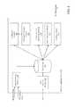
- FIG. 4is a diagram showing power usage and temperature readings as determined by predictions of the system in comparison to actual power usage and temperature readings.
- FIG. 1is a block diagram of a system 100 for optimizing and controlling the energy consumption of a building.
- the system 100includes a server computing device 102 , a communications network 104 , a thermostat device 106 that controls the heating and/or cooling apparatus for a building, and a client computing device 108 .
- the server computing device 102receives data from external sources (e.g., weather data, thermostat data) and determines energy response characteristics and energy requirements for a particular building.
- the server computing device 102determines a temperature set point for the building, and transmits the set point to the thermostat 106 via the network 104 so that the thermostat can adjust the heating/cooling conditions of the building appropriately.
- the server computing device 102also interfaces with a client computing device 108 via the network 104 to provide a portal (e.g., a web browser interface) through which a user can view the energy response characteristics and energy requirements for a building (e.g., the user's house).
- a portale.g., a web browser interface
- the usercan also, for example, manually adjust the temperature set points for the thermostat 106 , and set up a comfort profile with the user's heating/cooling preferences so the server computing device 102 can automatically adjust the thermostat 106 based on the comfort profile.
- FIG. 2is a detailed block diagram of the server computing device 102 for optimizing and controlling the energy consumption of a building.
- the server computing device 102includes a data receiving module 202 , a data storage 204 , a coefficient modeler 206 , a predictive outcome module 208 , an optimization and scheduling module 210 , a data verification module 212 , a sending module 214 , and a web interface module 216 . It should be appreciated that, although FIG.
- FIG. 2shows the components (e.g., 202 , 204 , 206 , 208 , 210 , 212 , 214 and 216 ) as within a single server computing device 102 , in some embodiments the components are distributed on different physical devices without departing from the spirit or scope of the invention. Also, in embodiments where the components are distributed on different physical devices, those devices can reside at the same physical location or may be dispersed to different physical locations.
- the data receiving module 202provides an interface between external data sources (e.g., weather databases, energy providers and building thermostats) and the data storage 204 of the server computing device 102 .
- the data receiving module 202receives data associated with atmospheric conditions and weather from various external data collection and/or monitoring systems (e.g., NWS, NOAA, Earth Networks Weather Network). Other sources of information include, but are not limited to, governmental agencies and third-party private companies.
- the atmospheric conditions and weather datacan include, but is not limited to, current conditions information, forecast information and weather alert information.
- the atmospheric conditions and weather datacan be categorized by location (e.g., zip code or GPS coordinates).
- the data receiving module 202communicates with the various external data systems and sources via standard communications networks and methods.
- the data receiving module 202also receives information from thermostat devices (e.g., thermostat 106 ) that are located within buildings and that control the heating and/or cooling apparatuses for the buildings. For example, the thermostat 106 transmits characteristics about its current operation status (e.g., current temperature setting, heating mode, cooling mode, power settings, efficiency conditions) to the server computing device 102 .
- the data receiving module 202also gathers information from a smart meter (e.g., electric meter, gas meter, or water meter) located at the building.
- the smart meteris configured to record consumption of energy in predetermined intervals (e.g., one hour) and communicate the recorded information to the utility that provides service to the building.
- the data receiving module 202can receive the recorded consumption information and correlate the energy usage with other types of data (e.g., thermostat data, exterior weather data) to determine how changes in outside weather conditions and adjustment of the thermostat settings impact energy consumption.
- the data receiving module 202consolidates and aggregates the received information into a format conducive for storage in the data storage 204 and processing by the modules 206 , 208 , 210 , 212 , 214 and 216 .
- each data source to which the data receiving module 202 is connectedmay transmit data using a different syntax and/or data structure.
- the data receiving module 202parses the incoming data according to an understanding of the source of the data and reformat the data so that it conforms to a syntax or structure acceptable to the data storage 204 and the modules 206 , 208 , 210 , 212 , 214 and 216 .
- the external data sourcestransmit the information in a standard format (e.g., XML) to reduce the processing required of the data receiving module 202 .
- the data receiving module 202communicates with the data storage 204 to save and retrieve data received from external sources in preparation for transmitting the data to the modules 206 , 208 , 210 , 212 , 214 and 216 .
- the data receiving module 202transmits a notification to the coefficient modeler 206 that the data has been stored in the data storage 204 and is ready for processing by the coefficient modeler 206 .
- the notificationincludes a reference indicator (e.g., a database address) of the storage location of the data within the data storage 204 .
- the data storage 204is a database or other similar data structure, including hardware (e.g., disk drives), software (e.g., database management programming) or both, that stores information received by the data receiving module 202 .
- the data storage 204also provides data to the modules 206 , 208 , 210 , 212 , 214 and 216 , and receives updated data and analysis from the modules 206 , 208 , 210 , 212 , 214 and 216 .
- the coefficient modeler 206is a module that retrieves information from the data storage 208 and generates sets of thermal response coefficients associated with energy characteristics of a building.
- the modeler 206determines the location of the building (e.g., by retrieving the building's zip code).
- the modeler 206retrieves additional data associated with the building, such as physical structure of the building (e.g., construction materials), solar orientation and load, thermal mass, and wind infiltration.
- the modeler 206infers the physical structure of the building, solar orientation and load, thermal mass, and/or wind infiltration based on the location of the building.
- the modeler 206retrieves smart meter data associated with the building that has been collected by the server computing device 102 from a smart meter installed at the building. In some embodiments, the modeler 206 extracts data from the data storage 204 in the form of a comma-separated value (.csv) file.
- the modeler 206determines a thermal profile for the building. Using the thermal profile in conjunction with the weather information for the location of the building, the current thermostat setting for the building, and other data associated with the building (e.g., smart meter data), the modeler 206 generates sets of thermal response coefficients based on the various characteristics that affect the heating/cooling of the building (e.g., thermal mass, solar loading, and wind infiltration) and the amount of energy consumed by the heating/cooling apparatus at the building. Each set of thermal response coefficients can be different, according to projections of the weather conditions at the location over a period of time (e.g., an hour, a day).
- a period of timee.g., an hour, a day
- the modeler 206ranks the sets of thermal response coefficients based on considerations of energy usage, forecast accuracy, occupant preferences, and the like.
- the modeler 206transmits the ranked thermal response coefficients to the data storage 204 for use by other modules 208 , 210 , 212 , 214 , 216 of the system 100 .
- the optimizing and scheduling module 210retrieves the ranked thermal response coefficients from the data storage 204 along with additional information, such as the weather forecast associated with the location of the building and an occupant preference profile associated with the building. In some embodiments, the optimizing and scheduling module 210 also retrieves current and estimated energy prices (e.g., from the data storage 204 or from an external data source such as a utility company). The optimizing and scheduling module 210 transmits the information to the predictive outcome module 208 .
- the predictive outcome module 208generates a series of temperature set points for the thermostat (e.g., thermostat 106 ) for the building, based on the current and forecast weather conditions for that location and each set of thermal response coefficients.
- the predictive outcome module 208also generates a power usage estimate, duty cycle, and indoor temperature forecast for the heating/cooling apparatus installed the building based on the series of temperature set points.
- the predictive outcome module 208can also generate an estimated energy cost associated with the series of temperature set points by incorporating current energy prices into the determination.
- the optimizing and scheduling module 210receives the series of temperature set points from the predictive outcome module 208 and optimizes the results based on additional factors such as anticipated demand response events and/or occupant preferences. For example, if the weather forecast indicates that the exterior temperature will rise from 70° F. at 8:30 am to 90° F. at 11:00 am, the optimizing and scheduling module 210 determines that there will be an increased demand for energy to power air conditioning systems at that time. The optimizing and scheduling module 210 also determines that the price of energy will go up at that time.
- the optimizing and scheduling module 210adjusts the series of temperature set points to provide additional cooling (i.e., pre-cool) to the home in the earlier part of the morning (e.g., 8:30 am) so that the air conditioner in the home does not need to run as long at 11:00 am when the exterior temperature is hotter. Also, the optimizing and scheduling module 210 understands that the price of energy at 8:30 am is lower than the predicted cost at 11:00 am, so an increased consumption of energy in the early morning achieves a cost savings versus consuming more energy at the later time of 11:00 am.
- the module 210transmits the series of temperature set points to the data storage 204 .
- the data storage 204transmits the series of temperature set points to the sending module 214 , which communicates the temperature set points to the thermostat 106 in the building.
- the temperature set pointsprovide a schedule of target temperatures for the thermostat 106 for a given time period (e.g., one day).
- the thermostat 106can perform heating and/or cooling according to the schedule of temperature set points to achieve increased energy efficiency and anticipation of demand response events.
- the server computing device 102also includes a data verification module 212 .
- the data verification module 212retrieves energy usage data for the building from a prior time period and compares the usage data to what was predicted by the system 100 for the same time period. For example, the data verification module 212 retrieves the energy usage data (e.g., as provided by a smart meter or from a utility) for a customer's home on a particular day. The data verification module 212 also retrieves the predicted energy usage for the same day, based on the determinations performed by the modeler 206 , predictive outcome module 208 and optimization and scheduling module 210 . The data verification module 212 compares the two energy usage values (actual vs. predicted) to determine if any deviations occurred.
- the data verification module 212can provide energy usage savings data that can be presented to the customer (e.g., via the web interface module 216 ). In some embodiments, the data verification module 212 determines energy savings using additional methodologies. For example, the data verification module 212 can compare a building's energy usage between (i) a day where the optimization and scheduling module 210 did not adjust the temperature set point schedule for the building's thermostat and (ii) a day where the optimization and scheduling module 210 did adjust the temperature set point schedule. The data verification module 212 can produce charts and other reports showing the energy savings achieved when the optimization and scheduling module 210 is run. In addition, the comparison information generated by the data verification module 212 is used to refine the coefficient models created by the modeler 206 to achieve greater accuracy and better efficiency.
- the server computing device 102also includes a web interface module 216 .
- the web interface module 216is configured to receive connection requests from client devices (e.g., client device 108 in FIG. 1 ) and provide a portal for the client devices to access and update the thermal profile information associated with a building.
- client devicese.g., client device 108 in FIG. 1
- a portalfor the client devices to access and update the thermal profile information associated with a building.
- a homeownercan register with the system 100 and connect to the web interface module 216 via a web browser on a client device 108 .
- the homeownerUpon logging in, the homeowner is presented with a portal containing various information related to the current energy characteristics of his home,
- the portalincludes a home energy audit function which leverages the data stored in the system 100 (e.g., thermal profile, energy usage, weather conditions) and compares the homeowner's dwelling with other buildings that share similar thermal and/or energy consumption characteristics. The homeowner can determine the relative energy usage of his home against other homes or buildings in his area. Based on the home energy audit, the portal can also provide a customized and prioritized list of suggestions for improving the energy efficiency of the building.
- a home energy audit functionleverages the data stored in the system 100 (e.g., thermal profile, energy usage, weather conditions) and compares the homeowner's dwelling with other buildings that share similar thermal and/or energy consumption characteristics. The homeowner can determine the relative energy usage of his home against other homes or buildings in his area. Based on the home energy audit, the portal can also provide a customized and prioritized list of suggestions for improving the energy efficiency of the building.
- FIG. 3is a flow diagram of a method 300 for optimizing and controlling the energy consumption of a building.
- the server computing device 102using the coefficient modeler 206 , generates ( 302 ) a set of thermal response coefficients for a building based on energy characteristics of the building and weather data associated with the location of the building.
- the server computing device 102using the optimization and scheduling module 210 and the predictive outcome module 208 , predicts ( 304 ) an energy response of the building based on the set of thermal response coefficients and forecasted weather conditions associated with the location of the building.
- the server computing device 102uses the optimization and scheduling module 210 and the predictive outcome module 208 , selects ( 306 ) minimal energy requirements of the building based on an energy consumption cost associated with the building.
- the server computing device 102uses the optimization and scheduling module 210 and the predictive outcome module 208 , determines ( 308 ) one or more temperature set points for the building based on the energy response and the minimal energy requirements.
- the server computing device 102using the data verification module 212 , compares the previous day's energy usage for the building against the predicted energy usage provided by the modeler 206 and the predictive outcome module 208 to determine energy usage deviations and potential energy savings.
- the server computing device 102using the sending module 214 , transmits ( 310 ) the one or more temperature set points to a thermostat 106 of the building.
- the techniques described hereinare used to execute demand response events in conjunction with local or regional utilities and service providers.
- the predictive modeling and thermostat control features of the system 100can be leveraged to prepare for potential demand response events identified by the utilities, and shift energy consumption by buildings connected to the system from peak demand times to lower demand times—thereby reducing the energy demand load on the utilities and potentially providing energy to the buildings at a lower cost.
- the server computing device 102determines that a certain amount of energy will be consumed by buildings connected to the system 100 over the course of the following day.
- the server computing device 102also determines that, based on weather forecast information, there may be a peak demand event for energy during a two-hour window the following day (e.g., due to forecast low/high external temperatures or a forecast change in external temperature). Because the server computing device 102 has identified an amount of energy that will be potentially used during that two-hour window, the server computing device 102 can proactively adjust the temperature set points for some or all of the thermostats (e.g., thermostat 106 ) to reduce or eliminate consumption of energy by the buildings during the peak demand time.
- the thermostatse.g., thermostat 106
- a utilitydoes not have advance warning of a potential demand response event. For example, the utility may not anticipate a demand response event until one hour before the event begins. At the point when the utility becomes aware of the demand response event, the utility can inform the server computing device 102 of the upcoming event. Based on its previous analysis, the server computing device 102 can commit a particular amount of energy to the utility that will not be consumed by buildings of the system 100 during the demand response event. If the utility notifies the system 100 that the utility requires the committed amount of energy, the server computing device 102 automatically transmits adjusted temperature set point schedules to the connected thermostats that reduce energy consumption by the amount of energy committed to the utility.
- the server computing device 102can also adjust the temperature set point schedules of the thermostats to account for the reduced energy consumption while approximately maintaining the temperature desired by the occupant and/or specified in the schedule. For example, if the server computing device 102 understands that the thermostat 106 will be adjusted to consume no energy during a demand response event (e.g., mid-afternoon on a summer day), the server computing device 102 can adjust the temperature set point schedule for the thermostat 106 to pre-cool the building in advance of the demand response event so that the temperature of the building is at or near the originally-scheduled value during the event. The additional energy consumed by the pre-cooling does not occur during the demand response event—leading to reduced load on the utility and potential cost savings for the occupant. Plus, the building approximately maintains a desired/scheduled temperature during the event.
- a demand response evente.g., mid-afternoon on a summer day
- a buildingis represented as a grey-box system balancing the sensible energy of the entire indoor environment with the flow of energy through the envelope.
- This type of modelingaccounts for heat diffusion through the walls, convection on the inner and outer walls, solar irradiance, infiltration, thermal mass, and HVAC system performance.
- HVAC status datais obtained from internet connected thermostats, and electricity data from smart meters.
- Transient temperatures within the wallare accounted for by solving for the temperatures at nodes within a uniform property wall using an explicit tridiagonal matrix algorithm.
- Inputs to the modelinclude outdoor temperature, solar insolation, and wind speed data from local weather stations, indoor air temperature, and HVAC status data from internet connected thermostats, and electricity data from smart meters. Instead of requiring detailed measurements of building characteristics such as insulation R-values and fenestration ratios, effective parameter values are calculated from the data.
- the exemplary solution techniqueconsists of using a Genetic Algorithm to obtain a least squares curve that fits the modeled indoor air temperatures to the measured temperatures.
- the parametersare updated periodically to account for changes in the weather and building status.
- Energy forecastsare made by running the model with weather forecast data, user thermostat set points, and in the case of demand response events, updated set points to reflect the particular strategy proposed to be deployed.
- Air conditionersutilize a vapor compression cycle and achieve cooling by absorbing heat from the indoor environment in the evaporator and rejecting it outside in the condenser. To get this heat transfer in the condenser, the refrigerant needs to be hotter than the outdoor air. Modern systems then compensate for variable outdoor air temperatures by adjusting the difference in pressure between the evaporator and condenser. When the outdoor temperature rises, this pressure differential (i.e., pressure ratio) needs to increase, requiring more power by the compressor. The same power variability with outdoor temperature is also observed in heat pumps.
- This temperature dependenceis important for predicting air conditioner load, and can be measured using thermostat and smart meter power data.
- An exemplary methodhas been developed that matches the smart meter data with HVAC ON/OFF time periods to determine approximate HVAC ON power spikes. These power spikes are binned by their outdoor air temperature. Then a linear regression of the binned data is used to create an HVAC power curve. This power curve can be used to approximate the load anytime the HVAC is on given outdoor temperature data or forecasts.
- FIG. 4is a diagram showing power usage and temperature readings as determined by predictions of the system 100 in comparison to actual power usage and temperature readings for an example building over an example time period.
- line 402represents the average actual power usage
- line 404represents the average power usage prediction as determined by the system 100
- line 406represents the average actual indoor temperature
- line 408represents the average indoor temperature prediction as determined by the system 100 .
- the data depicted in FIG. 4was captured during a demand response event.
- the techniques described hereinprovide accurate predictions of demand response capacity and the impact of demand response on indoor house temperatures.
- the deviations between actual and predicted values for both power (e.g., 402 , 404 ) and indoor temperature (e.g., 406 , 408 )are small and demonstrate the effectiveness of the system 100 in providing accurate predictions.
- the above-described techniquescan be implemented in digital and/or analog electronic circuitry, or in computer hardware, firmware, software, or in combinations of them.
- the implementationcan be as a computer program product, i.e., a computer program tangibly embodied in a machine-readable storage device, for execution by, or to control the operation of, a data processing apparatus, e.g., a programmable processor, a computer, and/or multiple computers.
- a computer programcan be written in any form of computer or programming language, including source code, compiled code, interpreted code and/or machine code, and the computer program can be deployed in any form, including as a stand-alone program or as a subroutine, element, or other unit suitable for use in a computing environment.
- a computer programcan be deployed to be executed on one computer or on multiple computers at one or more sites.
- Method stepscan be performed by one or more processors executing a computer program to perform functions of the invention by operating on input data and/or generating output data. Method steps can also be performed by, and an apparatus can be implemented as, special purpose logic circuitry, e.g., a FPGA (field programmable gate array), a FPAA (field-programmable analog array), a CPLD (complex programmable logic device), a PSoC (Programmable System-on-Chip), ASIP (application-specific instruction-set processor), or an ASIC (application-specific integrated circuit), or the like.
- Subroutinescan refer to portions of the stored computer program and/or the processor, and/or the special circuitry that implement one or more functions.
- processors suitable for the execution of a computer programinclude, by way of example, both general and special purpose microprocessors, and any one or more processors of any kind of digital or analog computer.
- a processorreceives instructions and data from a read-only memory or a random access memory or both.
- the essential elements of a computerare a processor for executing instructions and one or more memory devices for storing instructions and/or data.
- Memory devicessuch as a cache, can be used to temporarily store data. Memory devices can also be used for long-term data storage.
- a computeralso includes, or is operatively coupled to receive data from or transfer data to, or both, one or more mass storage devices for storing data, e.g., magnetic, magneto-optical disks, or optical disks.
- a computercan also be operatively coupled to a communications network in order to receive instructions and/or data from the network and/or to transfer instructions and/or data to the network.
- Computer-readable storage mediums suitable for embodying computer program instructions and datainclude all forms of volatile and non-volatile memory, including by way of example semiconductor memory devices, e.g., DRAM, SRAM, EPROM, EEPROM, and flash memory devices; magnetic disks, e.g., internal hard disks or removable disks; magneto-optical disks; and optical disks, e.g., CD, DVD, HD-DVD, and Blu-ray disks.
- the processor and the memorycan be supplemented by and/or incorporated in special purpose logic circuitry.
- the above described techniquescan be implemented on a computer in communication with a display device, e.g., a CRT (cathode ray tube), plasma, or LCD (liquid crystal display) monitor, for displaying information to the user and a keyboard and a pointing device, e.g., a mouse, a trackball, a touchpad, or a motion sensor, by which the user can provide input to the computer (e.g., interact with a user interface element).
- a display devicee.g., a CRT (cathode ray tube), plasma, or LCD (liquid crystal display) monitor
- a keyboard and a pointing devicee.g., a mouse, a trackball, a touchpad, or a motion sensor, by which the user can provide input to the computer (e.g., interact with a user interface element).
- feedback provided to the usercan be any form of sensory feedback, e.g., visual feedback, auditory feedback, or tactile feedback; and input from the user can be received in any form, including acoustic, speech, and/or tactile input.
- feedback provided to the usercan be any form of sensory feedback, e.g., visual feedback, auditory feedback, or tactile feedback
- input from the usercan be received in any form, including acoustic, speech, and/or tactile input.
- the above described techniquescan be implemented in a distributed computing system that includes a back-end component.
- the back-end componentcan, for example, be a data server, a middleware component, and/or an application server.
- the above described techniquescan be implemented in a distributed computing system that includes a front-end component.
- the front-end componentcan, for example, be a client computer having a graphical user interface, a Web browser through which a user can interact with an example implementation, and/or other graphical user interfaces for a transmitting device.
- the above described techniquescan be implemented in a distributed computing system that includes any combination of such back-end, middleware, or front-end components.
- Transmission mediumcan include any form or medium of digital or analog data communication (e.g., a communication network).
- Transmission mediumcan include one or more packet-based networks and/or one or more circuit-based networks in any configuration.
- Packet-based networkscan include, for example, the Internet, a carrier internet protocol (IP) network (e.g., local area network (LAN), wide area network (WAN), campus area network (CAN), metropolitan area network (MAN), home area network (HAN)), a private IP network, an IP private branch exchange (IPBX), a wireless network (e.g., radio access network (RAN), Bluetooth, Wi-Fi, WiMAX, general packet radio service (GPRS) network, HiperLAN), and/or other packet-based networks.
- IPcarrier internet protocol
- RANradio access network
- GPRSgeneral packet radio service
- HiperLANHiperLAN
- Circuit-based networkscan include, for example, the public switched telephone network (PSTN), a legacy private branch exchange (PBX), a wireless network (e.g., RAN, code-division multiple access (CDMA) network, time division multiple access (TDMA) network, global system for mobile communications (GSM) network), and/or other circuit-based networks.
- PSTNpublic switched telephone network
- PBXlegacy private branch exchange
- CDMAcode-division multiple access
- TDMAtime division multiple access
- GSMglobal system for mobile communications
- Communication protocolscan include, for example, Ethernet protocol, Internet Protocol (IP), Voice over IP (VOIP), a Peer-to-Peer (P2P) protocol, Hypertext Transfer Protocol (HTTP), Session Initiation Protocol (SIP), H.323, Media Gateway Control Protocol (MGCP), Signaling System #7 (SS7), a Global System for Mobile Communications (GSM) protocol, a Push-to-Talk (PTT) protocol, a PTT over Cellular (POC) protocol, and/or other communication protocols.
- IPInternet Protocol
- VOIPVoice over IP
- P2PPeer-to-Peer
- HTTPHypertext Transfer Protocol
- SIPSession Initiation Protocol
- H.323H.323
- MGCPMedia Gateway Control Protocol
- SS7Signaling System #7
- GSMGlobal System for Mobile Communications
- PTTPush-to-Talk
- POCPTT over Cellular
- Devices of the computing systemcan include, for example, a computer, a computer with a browser device, a telephone, an IP phone, a mobile device (e.g., cellular phone, personal digital assistant (PDA) device, laptop computer, electronic mail device), and/or other communication devices.
- the browser deviceincludes, for example, a computer (e.g., desktop computer, laptop computer) with a World Wide Web browser (e.g., Microsoft® Internet Explorer® available from Microsoft Corporation, Mozilla® Firefox available from Mozilla Corporation).
- Mobile computing deviceinclude, for example, a Blackberry®.
- IP phonesinclude, for example, a Cisco® Unified IP Phone 7985G available from Cisco Systems, Inc, and/or a Cisco® Unified Wireless Phone 7920 available from Cisco Systems, Inc.
- Comprise, include, and/or plural forms of eachare open ended and include the listed parts and can include additional parts that are not listed. And/or is open ended and includes one or more of the listed parts and combinations of the listed parts.
Landscapes
- Engineering & Computer Science (AREA)
- General Physics & Mathematics (AREA)
- Physics & Mathematics (AREA)
- Automation & Control Theory (AREA)
- Computer Vision & Pattern Recognition (AREA)
- Health & Medical Sciences (AREA)
- Artificial Intelligence (AREA)
- Evolutionary Computation (AREA)
- Medical Informatics (AREA)
- Software Systems (AREA)
- Radar, Positioning & Navigation (AREA)
- Electromagnetism (AREA)
- Power Engineering (AREA)
- General Engineering & Computer Science (AREA)
- Air Conditioning Control Device (AREA)
Abstract
Description
Claims (59)
Priority Applications (4)
| Application Number | Priority Date | Filing Date | Title |
|---|---|---|---|
| US13/729,501US9261863B2 (en) | 2012-01-23 | 2012-12-28 | Optimizing and controlling the energy consumption of a building |
| US14/588,699US9612591B2 (en) | 2012-01-23 | 2015-01-02 | Optimizing and controlling the energy consumption of a building |
| US15/017,499US9471082B2 (en) | 2012-01-23 | 2016-02-05 | Optimizing and controlling the energy consumption of a building |
| US15/478,885US10354345B2 (en) | 2012-01-23 | 2017-04-04 | Optimizing and controlling the energy consumption of a building |
Applications Claiming Priority (2)
| Application Number | Priority Date | Filing Date | Title |
|---|---|---|---|
| US201261589639P | 2012-01-23 | 2012-01-23 | |
| US13/729,501US9261863B2 (en) | 2012-01-23 | 2012-12-28 | Optimizing and controlling the energy consumption of a building |
Related Child Applications (2)
| Application Number | Title | Priority Date | Filing Date |
|---|---|---|---|
| US14/588,699Continuation-In-PartUS9612591B2 (en) | 2012-01-23 | 2015-01-02 | Optimizing and controlling the energy consumption of a building |
| US15/017,499ContinuationUS9471082B2 (en) | 2012-01-23 | 2016-02-05 | Optimizing and controlling the energy consumption of a building |
Publications (2)
| Publication Number | Publication Date |
|---|---|
| US20130190940A1 US20130190940A1 (en) | 2013-07-25 |
| US9261863B2true US9261863B2 (en) | 2016-02-16 |
Family
ID=48797881
Family Applications (2)
| Application Number | Title | Priority Date | Filing Date |
|---|---|---|---|
| US13/729,501Active2033-12-23US9261863B2 (en) | 2012-01-23 | 2012-12-28 | Optimizing and controlling the energy consumption of a building |
| US15/017,499ActiveUS9471082B2 (en) | 2012-01-23 | 2016-02-05 | Optimizing and controlling the energy consumption of a building |
Family Applications After (1)
| Application Number | Title | Priority Date | Filing Date |
|---|---|---|---|
| US15/017,499ActiveUS9471082B2 (en) | 2012-01-23 | 2016-02-05 | Optimizing and controlling the energy consumption of a building |
Country Status (9)
| Country | Link |
|---|---|
| US (2) | US9261863B2 (en) |
| EP (2) | EP2807527B1 (en) |
| JP (3) | JP6215843B2 (en) |
| KR (1) | KR20140148370A (en) |
| CN (1) | CN104303125B (en) |
| AU (2) | AU2013212256A1 (en) |
| BR (1) | BR112014017966A8 (en) |
| CA (1) | CA2862119C (en) |
| WO (1) | WO2013112574A1 (en) |
Cited By (24)
| Publication number | Priority date | Publication date | Assignee | Title |
|---|---|---|---|---|
| US20150268650A1 (en)* | 2014-03-24 | 2015-09-24 | Nec Laboratories America, Inc. | Power modeling based building demand management system |
| US20160103475A1 (en)* | 2014-10-10 | 2016-04-14 | Lg Electronics Inc. | Central control apparatus for controlling facilities, facility control system including the same, and method of controlling facilities |
| US20160162297A1 (en)* | 2013-08-30 | 2016-06-09 | Hewlett-Packard Development Company, L.P. | Thermal Profile Based on Temperature Information for Computing Device Location |
| US20160195866A1 (en)* | 2013-03-13 | 2016-07-07 | Johnson Controls Technology Company | Systems and methods for energy cost optimization in a building system |
| US10088814B2 (en) | 2013-03-13 | 2018-10-02 | Johnson Controls Technology Company | System identification and model development |
| US10116747B2 (en) | 2013-02-05 | 2018-10-30 | Txu Energy Retail Company Llc | Electricity provider content platform |
| US10204310B2 (en) | 2015-01-16 | 2019-02-12 | Txu Energy Retail Company Llc | System and method for home automation |
| US10354345B2 (en) | 2012-01-23 | 2019-07-16 | Whisker Labs, Inc. | Optimizing and controlling the energy consumption of a building |
| US10380705B2 (en) | 2013-10-30 | 2019-08-13 | Carrier Corporation | System and method for modeling of target infrastructure for energy management in distributed-facilities |
| US20190252878A1 (en)* | 2016-09-29 | 2019-08-15 | Enel X North America, Inc. | Comfort management system employing automated validation, estimation, and editing rules |
| US10437942B2 (en) | 2015-04-03 | 2019-10-08 | Baidu Online Network Technology (Beijing) Co. Ltd. | Kalman filter based capacity forecasting method, system and computer equipment |
| US10580097B2 (en) | 2013-03-13 | 2020-03-03 | Johnson Controls Technology Company | Systems and methods for cascaded model predictive control |
| US10886734B2 (en) | 2016-09-29 | 2021-01-05 | Enel X North America, Inc. | Automated processor for validation, estimation, and editing |
| US10890934B2 (en) | 2016-09-29 | 2021-01-12 | Enel X North America, Inc. | Energy control system employing automated validation, estimation, and editing rules |
| US10935405B1 (en) | 2017-05-12 | 2021-03-02 | Alarm.Com Incorporated | Disaggregation of water consumption data |
| US10955867B2 (en) | 2016-09-29 | 2021-03-23 | Enel X North America, Inc. | Building control automated building control employing validation, estimation, and editing rules |
| US10969754B2 (en) | 2016-09-29 | 2021-04-06 | Enel X North America, Inc. | Comfort control system employing automated validation, estimation and editing rules |
| US10996638B2 (en) | 2016-09-29 | 2021-05-04 | Enel X North America, Inc. | Automated detection and correction of values in energy consumption streams |
| US11162703B2 (en) | 2016-08-19 | 2021-11-02 | Fraunhofer Usa, Inc. | System and method for characterization of retrofit opportunities in building using data from communicating thermostats |
| US11326805B2 (en) | 2019-03-15 | 2022-05-10 | Carrier Corporation | Control method for air conditioning system |
| US11462906B2 (en)* | 2015-03-31 | 2022-10-04 | Enel X North America, Inc. | Energy grid control system |
| US11662267B2 (en) | 2019-06-14 | 2023-05-30 | Alarm.Com Incorporated | Smart water valve |
| US20240003571A1 (en)* | 2013-11-04 | 2024-01-04 | Ademco Inc. | Remote contractor system with site specific energy audit capability |
| US12181374B2 (en) | 2020-07-24 | 2024-12-31 | Alarm.Com Incorporated | Dynamic water leak detection |
Families Citing this family (108)
| Publication number | Priority date | Publication date | Assignee | Title |
|---|---|---|---|---|
| JP3131952B2 (en) | 1991-12-19 | 2001-02-05 | 住友電気工業株式会社 | Optical fiber fusion splicer |
| US8332178B2 (en) | 2004-04-13 | 2012-12-11 | Honeywell International Inc. | Remote testing of HVAC systems |
| US10373082B2 (en)* | 2011-02-24 | 2019-08-06 | Qcoefficient, Inc. | Integration of commercial building operations with electric system operations and markets |
| US10663500B2 (en) | 2011-07-25 | 2020-05-26 | Clean Power Research, L.L.C. | System and method for estimating photovoltaic energy generation through linearly interpolated irradiance observations with the aid of a digital computer |
| US11068563B2 (en) | 2011-07-25 | 2021-07-20 | Clean Power Research, L.L.C. | System and method for normalized ratio-based forecasting of photovoltaic power generation system degradation with the aid of a digital computer |
| WO2013040539A1 (en)* | 2011-09-16 | 2013-03-21 | Siemens Corporation | Method and system for energy control management |
| WO2013106576A1 (en)* | 2012-01-13 | 2013-07-18 | Shoppertrak Rct Corporation | System and method for managing energy |
| US9261863B2 (en) | 2012-01-23 | 2016-02-16 | Earth Networks, Inc. | Optimizing and controlling the energy consumption of a building |
| US9612591B2 (en) | 2012-01-23 | 2017-04-04 | Earth Networks, Inc. | Optimizing and controlling the energy consumption of a building |
| US9312698B2 (en)* | 2012-12-19 | 2016-04-12 | Robert Bosch Gmbh | System and method for energy distribution |
| US9810442B2 (en)* | 2013-03-15 | 2017-11-07 | Google Inc. | Controlling an HVAC system in association with a demand-response event with an intelligent network-connected thermostat |
| US10371405B2 (en)* | 2013-03-21 | 2019-08-06 | Cornell University | Building power management systems |
| US9518873B2 (en)* | 2013-06-27 | 2016-12-13 | Google Technology Holdings LLC | Electronic system and method for thermal management therein taking into account solar thermal loading |
| US10902531B1 (en) | 2013-08-07 | 2021-01-26 | Promanthan Brains LLC | Predictive thermostat |
| CN103499136B (en)* | 2013-09-26 | 2017-01-04 | 中铁建设集团有限公司 | Ice storage control system with next-day energy consumption simulation function |
| WO2015077754A1 (en)* | 2013-11-25 | 2015-05-28 | Siemens Corporation | A statistical approach to modeling and forecast of cchp energy and cooling demand and optimization cchp control setpoints |
| US10885238B1 (en)* | 2014-01-09 | 2021-01-05 | Opower, Inc. | Predicting future indoor air temperature for building |
| US10789396B1 (en) | 2014-02-03 | 2020-09-29 | Clean Power Research, L.L.C. | Computer-implemented system and method for facilitating implementation of holistic zero net energy consumption |
| US10719636B1 (en) | 2014-02-03 | 2020-07-21 | Clean Power Research, L.L.C. | Computer-implemented system and method for estimating gross energy load of a building |
| US10024733B1 (en) | 2014-02-03 | 2018-07-17 | Clean Power Research, L.L.C. | Apparatus and method for empirically estimating overall thermal performance of a building with the aid of a digital computer |
| US9727063B1 (en)* | 2014-04-01 | 2017-08-08 | Opower, Inc. | Thermostat set point identification |
| US20150330923A1 (en)* | 2014-05-15 | 2015-11-19 | Palo Alto Research Center Incorporated | Computer-Implemented System And Method For Externally Assessing A Building's Susceptibility To Heat Loads |
| DE102014210153B4 (en)* | 2014-05-28 | 2022-10-27 | Robert Bosch Gmbh | Method for operating a control unit of a heating system |
| US10185345B2 (en) | 2015-06-22 | 2019-01-22 | Solarcity Corporation | Systems and methods of home efficiency modeling |
| US9485344B2 (en)* | 2014-12-01 | 2016-11-01 | Honeywell International Inc. | Personalizing interaction with a structure |
| US9846881B2 (en)* | 2014-12-19 | 2017-12-19 | Palo Alto Research Center Incorporated | Frugal user engagement help systems |
| EP3241079B1 (en)* | 2015-01-02 | 2020-03-18 | Earth Networks, Inc. | Optimizing and controlling the energy consumption of a building |
| FR3031401B1 (en) | 2015-01-06 | 2017-07-14 | Ubiant Sa | SYSTEM FOR MANAGING THE ENERGY CONSUMPTION OF A BUILDING |
| FR3031598A1 (en)* | 2015-01-13 | 2016-07-15 | Ecometering | IMPROVED THERMAL DEVICE |
| US11921478B2 (en) | 2015-02-25 | 2024-03-05 | Clean Power Research, L.L.C. | System and method for estimating periodic fuel consumption for cooling of a building with the aid of a digital computer |
| US10339232B1 (en)* | 2015-02-25 | 2019-07-02 | Clean Power Research, L.L.C. | Computer-implemented system and method for modeling building heating energy consumption |
| US10156554B1 (en) | 2015-02-25 | 2018-12-18 | Clean Power Research, L.L.C. | System and method for determining infiltration of a building through empirical testing using a CO2 concentration monitoring device |
| JP6527374B2 (en)* | 2015-04-13 | 2019-06-05 | アズビル株式会社 | Information presentation apparatus, information presentation method and information presentation system |
| US11216020B2 (en) | 2015-05-04 | 2022-01-04 | Johnson Controls Tyco IP Holdings LLP | Mountable touch thermostat using transparent screen technology |
| AU2016257459B2 (en) | 2015-05-04 | 2019-04-04 | Johnson Controls Technology Company | Multi-function home control system with control system hub and remote sensors |
| US10677484B2 (en) | 2015-05-04 | 2020-06-09 | Johnson Controls Technology Company | User control device and multi-function home control system |
| US10288321B2 (en) | 2015-05-11 | 2019-05-14 | Siemens Industry, Inc. | Energy-efficient integrated lighting, daylighting, and HVAC with electrochromic glass |
| US9708852B2 (en) | 2015-05-11 | 2017-07-18 | Siemens Industry, Inc. | Energy-efficient integrated lighting, daylighting, and HVAC with controlled window blinds |
| US10935275B2 (en) | 2015-05-29 | 2021-03-02 | Carrier Corporation | HVAC system thermal recovery |
| CN107743569B (en)* | 2015-06-08 | 2021-07-23 | 开利公司 | HVAC system start/stop control |
| WO2016207908A1 (en)* | 2015-06-21 | 2016-12-29 | Solanki Rajesh Ramnik | System for monitoring and controlling devices and method thereof |
| US10690364B2 (en)* | 2015-09-08 | 2020-06-23 | International Business Machines Corporation | Predictive analytics to determine optimal structure control |
| US10410300B2 (en) | 2015-09-11 | 2019-09-10 | Johnson Controls Technology Company | Thermostat with occupancy detection based on social media event data |
| US10760809B2 (en) | 2015-09-11 | 2020-09-01 | Johnson Controls Technology Company | Thermostat with mode settings for multiple zones |
| US11277893B2 (en) | 2015-10-28 | 2022-03-15 | Johnson Controls Technology Company | Thermostat with area light system and occupancy sensor |
| US10655881B2 (en) | 2015-10-28 | 2020-05-19 | Johnson Controls Technology Company | Thermostat with halo light system and emergency directions |
| US10345781B2 (en) | 2015-10-28 | 2019-07-09 | Johnson Controls Technology Company | Multi-function thermostat with health monitoring features |
| US10546472B2 (en) | 2015-10-28 | 2020-01-28 | Johnson Controls Technology Company | Thermostat with direction handoff features |
| US10318266B2 (en) | 2015-11-25 | 2019-06-11 | Johnson Controls Technology Company | Modular multi-function thermostat |
| US10452034B2 (en)* | 2015-12-16 | 2019-10-22 | Johnson Controls Technology Company | Central plant control system with building energy load estimation |
| US11237528B2 (en) | 2016-02-16 | 2022-02-01 | Ademco Inc. | System and method for handing off the configuration of a building device from a contractor to a customer using a hang tag or the like |
| US10812285B2 (en) | 2016-02-16 | 2020-10-20 | Ademco Inc. | Systems and methods for handing off configuration of a building device from a contractor to a customer |
| US10820199B2 (en) | 2016-02-16 | 2020-10-27 | Ademco Inc. | Mobile device with contractor accessible screens for configuring a building device |
| US9951967B2 (en) | 2016-02-26 | 2018-04-24 | Johns Manville | Thermal energy storage systems and methods for use with solar power generation systems |
| EP3214718B1 (en)* | 2016-03-01 | 2019-12-04 | Siemens Aktiengesellschaft | Method and system for operating a self-sufficient energy supply network |
| US10072865B2 (en)* | 2016-04-14 | 2018-09-11 | Schneider Electric It Corporation | Systems and methods for minimizing compressor use in HVAC systems |
| WO2017192752A1 (en)* | 2016-05-04 | 2017-11-09 | Johnson Controls Technology Company | User control device and multi-function home control system |
| US10969127B2 (en) | 2016-08-18 | 2021-04-06 | Ademco Inc. | Residential energy efficiency rating system |
| US10088192B2 (en)* | 2016-10-06 | 2018-10-02 | Google Llc | Thermostat algorithms and architecture for efficient operation at low temperatures |
| US10274920B2 (en)* | 2016-10-30 | 2019-04-30 | Carrier Corporation | Method and system for determining energy savings target for distributed sites of an entity |
| US10359206B1 (en) | 2016-11-03 | 2019-07-23 | Clean Power Research, L.L.C. | System and method for forecasting seasonal fuel consumption for indoor thermal conditioning with the aid of a digital computer |
| EP3242182B1 (en)* | 2017-02-14 | 2022-06-29 | Grundfos Holding A/S | Method for carrying out outside temperature-related control and corresponding server. |
| US11162698B2 (en) | 2017-04-14 | 2021-11-02 | Johnson Controls Tyco IP Holdings LLP | Thermostat with exhaust fan control for air quality and humidity control |
| WO2018200861A1 (en)* | 2017-04-27 | 2018-11-01 | Johnson Controls Technology Company | Building energy system with stochastic model predictive control |
| DE102017112505A1 (en)* | 2017-06-07 | 2018-12-13 | Innogy Se | Method for operating a thermal consumption system |
| US10838441B2 (en)* | 2017-11-28 | 2020-11-17 | Johnson Controls Technology Company | Multistage HVAC system with modulating device demand control |
| US10838440B2 (en)* | 2017-11-28 | 2020-11-17 | Johnson Controls Technology Company | Multistage HVAC system with discrete device selection prioritization |
| CA3082781A1 (en)* | 2017-12-07 | 2019-06-13 | Optimum Energy, Llc | Remote automated deployment of hvac optimization software |
| CN107994574B (en)* | 2017-12-13 | 2021-07-16 | 国网辽宁省电力有限公司葫芦岛供电公司 | Decision-making method of centralized temperature-controlled load-side demand response for new energy consumption |
| KR102049005B1 (en)* | 2017-12-21 | 2019-11-26 | 가천대학교 산학협력단 | Centralized HVAC System Using Genetic Algorithm and Method Using The Same |
| CN108224548B (en)* | 2017-12-29 | 2020-05-05 | 新奥泛能网络科技股份有限公司 | Energy supply day number calculation method |
| WO2019157584A1 (en)* | 2018-02-14 | 2019-08-22 | Iot Technologies Inc. | Weather anticipating programmable thermostat and wireless network ptac control |
| WO2019182972A1 (en)* | 2018-03-19 | 2019-09-26 | Carrier Corporation | Predicting the impact of flexible energy demand on thermal comfort |
| US10539336B2 (en) | 2018-03-29 | 2020-01-21 | Rcs Technology, Llc | Server-based thermostat control |
| CN109461091B (en)* | 2018-05-25 | 2020-08-28 | 中国农业大学 | Power utilization load calculation method considering correlation between photovoltaic load and cold load and information system |
| KR102198817B1 (en)* | 2018-09-12 | 2021-01-05 | 주식회사 석영시스템즈 | A method for creating demand response determination model for hvac system and a method for demand response |
| EP3637217A1 (en)* | 2018-10-08 | 2020-04-15 | E.ON Sverige AB | A method for controlling a thermal energy distribution system |
| US10859281B2 (en) | 2018-10-10 | 2020-12-08 | Ademco Inc. | Thermostat assembly with removable trim ring |
| US11236923B2 (en) | 2018-10-10 | 2022-02-01 | Ademco Inc. | Thermostat with sensor priority screen |
| US11067307B2 (en) | 2018-10-10 | 2021-07-20 | Ademco Inc. | Thermostat user interface with smart menu structure |
| US10907852B2 (en) | 2018-10-10 | 2021-02-02 | Ademco Inc. | Remote sensor with improved occupancy sensing |
| US10907854B2 (en) | 2018-10-10 | 2021-02-02 | Ademco Inc. | Automatic changeover mode in an HVAC controller with reversible deadband enforcement |
| US10908001B2 (en) | 2018-10-10 | 2021-02-02 | Ademco Inc. | Wireless sensor with mounting plate |
| US10816230B2 (en) | 2018-10-10 | 2020-10-27 | Ademco Inc. | Temperature sensing strategy with multiple temperature sensors |
| US11095469B2 (en) | 2018-10-10 | 2021-08-17 | Ademco Inc. | Wireless occupancy sensor with controllable light indicator |
| US10895397B2 (en) | 2018-10-10 | 2021-01-19 | Ademco Inc. | Wire detection for an HVAC controller |
| GB2578316B (en)* | 2018-10-23 | 2021-04-14 | Wirth Res Limited | A building management system and method |
| US11107390B2 (en) | 2018-12-21 | 2021-08-31 | Johnson Controls Technology Company | Display device with halo |
| KR102182609B1 (en) | 2019-01-23 | 2020-11-24 | 최보규 | Energy saving systems and methods of grain storage and grain processing plants |
| KR20200103381A (en) | 2019-02-25 | 2020-09-02 | (주)허브플렛폼 | Method for collecting data of multi-channel online shopping mall site |
| EP3715738A1 (en)* | 2019-03-29 | 2020-09-30 | Mitsubishi Electric R&D Centre Europe B.V. | Air conditioning system, server system, network, method for controlling an air conditioning system and method for controlling a network |
| US11295255B2 (en) | 2019-03-29 | 2022-04-05 | Datakwip Holdings, LLC | Facility analytics |
| US10558937B1 (en)* | 2019-04-22 | 2020-02-11 | Lineage Logistics Llc | Scheduled thermal control system |
| US11661948B2 (en) | 2019-05-10 | 2023-05-30 | Carrier Corporation | Compressor with vibration sensor |
| US11962152B2 (en) | 2019-05-31 | 2024-04-16 | Carrier Corporation | Method for supervisory control of building power consumption |
| CN110285855B (en)* | 2019-06-28 | 2021-05-04 | 江苏建筑职业技术学院 | Regional building energy consumption monitoring method |
| CN110544175A (en)* | 2019-07-11 | 2019-12-06 | 天津大学 | A Multi-Energy Comprehensive Optimal Dispatch Method for Household Intelligent Power Consumption |
| US11337276B2 (en)* | 2020-01-22 | 2022-05-17 | Dell Products L.P. | Environmental management based on temporal and spatial predicitons |
| US11719458B2 (en)* | 2020-04-16 | 2023-08-08 | Robert Bosch Gmbh | HVAC control fine-grained occupancy pattern estimation |
| EP3916492B1 (en) | 2020-05-25 | 2025-07-02 | Grundfos Holding A/S | Method and system for controlling a fluid transport system |
| US20220044338A1 (en)* | 2020-08-04 | 2022-02-10 | Johnson Controls Technology Company | Operations and maintenance development tool |
| FR3113313B1 (en)* | 2020-08-05 | 2023-03-24 | Accenta | Method and installations for supplying energy, in particular thermal energy, in at least one building or the like, and system relating thereto |
| KR102747287B1 (en)* | 2020-08-20 | 2024-12-31 | 삼성전자주식회사 | Control device, air conditioner and cotrol method thereof |
| KR20200132816A (en) | 2020-11-18 | 2020-11-25 | 최보규 | Methods for energy saving of grain storage and grain processing facilities |
| CN113065190B (en)* | 2021-04-15 | 2022-05-27 | 天津大学 | Uncertainty-based residential building heat supply amount calculation method |
| KR102520715B1 (en) | 2021-11-17 | 2023-04-10 | 연세대학교 산학협력단 | Method and device for automatic heating and cooling control using indoor and outdoor environment change prediction |
| IT202200011294A1 (en)* | 2022-05-27 | 2023-11-27 | Ariston Spa | ENERGY CONSUMPTION ESTIMATOR FOR AIR CONDITIONING SYSTEMS |
| US20240185149A1 (en)* | 2022-12-05 | 2024-06-06 | Saudi Arabian Oil Company | Forecasting energy demand and co2 emissions for a gas processing plant integrated with power generation facilities |
Citations (17)
| Publication number | Priority date | Publication date | Assignee | Title |
|---|---|---|---|---|
| US5936776A (en) | 1996-09-27 | 1999-08-10 | U.S. Precision Lens Inc. | Focusable front projection lens systems for use with large screen formats |
| US6098893A (en) | 1998-10-22 | 2000-08-08 | Honeywell Inc. | Comfort control system incorporating weather forecast data and a method for operating such a system |
| US6216956B1 (en) | 1997-10-29 | 2001-04-17 | Tocom, Inc. | Environmental condition control and energy management system and method |
| US6577962B1 (en) | 2000-09-28 | 2003-06-10 | Silicon Energy, Inc. | System and method for forecasting energy usage load |
| US20050102068A1 (en) | 2002-04-01 | 2005-05-12 | Pimputkar Sudheer M. | Energy management system |
| US20060255165A1 (en) | 2005-05-13 | 2006-11-16 | Samsung Electronics Co., Ltd. | Operation control apparatus and method for air conditioner using airwave broadcast data |
| US20070112939A1 (en) | 2005-11-17 | 2007-05-17 | Sbc Knowledge Ventures L.P. | System and method for home automation |
| US20100106334A1 (en) | 2008-10-27 | 2010-04-29 | Lennox Industries Inc. | System and method for zoning a distributed architecture heating, ventilation and air conditioning network |
| US7848900B2 (en) | 2008-09-16 | 2010-12-07 | Ecofactor, Inc. | System and method for calculating the thermal mass of a building |
| US20100332373A1 (en) | 2009-02-26 | 2010-12-30 | Jason Crabtree | System and method for participation in energy-related markets |
| US7908117B2 (en) | 2007-08-03 | 2011-03-15 | Ecofactor, Inc. | System and method for using a network of thermostats as tool to verify peak demand reduction |
| US20110178977A1 (en) | 2009-06-22 | 2011-07-21 | Johnson Controls Technology Company | Building management system with fault analysis |
| US8010237B2 (en) | 2008-07-07 | 2011-08-30 | Ecofactor, Inc. | System and method for using ramped setpoint temperature variation with networked thermostats to improve efficiency |
| US8019567B2 (en) | 2007-09-17 | 2011-09-13 | Ecofactor, Inc. | System and method for evaluating changes in the efficiency of an HVAC system |
| US8090477B1 (en) | 2010-08-20 | 2012-01-03 | Ecofactor, Inc. | System and method for optimizing use of plug-in air conditioners and portable heaters |
| US8108492B2 (en) | 1995-11-13 | 2012-01-31 | Lakshmi Arunachalam | Web application network portal |
| US20130060471A1 (en)* | 2010-07-19 | 2013-03-07 | Mark A. Aschheim | Estimating energy savings and carbon offsets for buildings in real-time |
Family Cites Families (21)
| Publication number | Priority date | Publication date | Assignee | Title |
|---|---|---|---|---|
| JP2512262B2 (en)* | 1992-05-08 | 1996-07-03 | 松下電器産業株式会社 | Indoor temperature setting device for air conditioners |
| JP2002364901A (en)* | 2001-06-07 | 2002-12-18 | Hitachi Ltd | Control system for regenerative air conditioning equipment, control planning device, control planning method, recording medium and program for executing control planning |
| US6993417B2 (en) | 2001-09-10 | 2006-01-31 | Osann Jr Robert | System for energy sensing analysis and feedback |
| JP4487550B2 (en)* | 2002-12-10 | 2010-06-23 | パナソニック電工株式会社 | Environmental equipment control system |
| US7216021B2 (en)* | 2003-10-30 | 2007-05-08 | Hitachi, Ltd. | Method, system and computer program for managing energy consumption |
| GB2408592B (en)* | 2003-11-27 | 2005-11-16 | James Ian Oswald | Household energy management system |
| US10705549B2 (en)* | 2003-12-02 | 2020-07-07 | Ademco Inc. | Controller interface with menu schedule override |
| US7502768B2 (en)* | 2004-02-27 | 2009-03-10 | Siemens Building Technologies, Inc. | System and method for predicting building thermal loads |
| JP2009115359A (en)* | 2007-11-05 | 2009-05-28 | Daikin Ind Ltd | Air conditioning control device, air conditioner, and air conditioning control method |
| US20100019050A1 (en)* | 2008-07-25 | 2010-01-28 | Gm Global Technology Operations, Inc. | Automatic Climate Control for a Vehicle |
| JP5227707B2 (en)* | 2008-09-12 | 2013-07-03 | 株式会社日立製作所 | Air-conditioning energy-saving control device |
| CN102812303B (en) | 2009-12-16 | 2016-03-30 | 国家科学和工业研究组织 | HVAC control system and method |
| US20110218690A1 (en)* | 2010-03-05 | 2011-09-08 | Efficient Energy America Incorporated | System and method for providing automated electrical energy demand management |
| JP4951082B2 (en)* | 2010-03-18 | 2012-06-13 | 株式会社東芝 | Energy saving advice generator |
| GB201005320D0 (en) | 2010-03-30 | 2010-05-12 | Telepure Ltd | Improvements in controllers, particularly controllers for use in heating, ventilation and air conditioning systems |
| CN101825327B (en)* | 2010-05-28 | 2012-03-07 | 哈尔滨工业大学 | Method for acquiring optimum air-conditioning system operation parameters based on weather forecast |
| CN102156463B (en)* | 2011-03-25 | 2013-05-08 | 浙江汉爵科技有限公司 | Planning management control system for construction energy |
| CN102193544B (en)* | 2011-03-25 | 2013-06-05 | 汉鼎信息科技股份有限公司 | Intelligent building energy management system |
| CN103648435A (en) | 2011-06-14 | 2014-03-19 | 杰.尔.辛普洛公司 | Method for identifying a mammal receptive to embryo transfer |
| US9261863B2 (en) | 2012-01-23 | 2016-02-16 | Earth Networks, Inc. | Optimizing and controlling the energy consumption of a building |
| US9377791B2 (en) | 2012-10-08 | 2016-06-28 | International Business Machines Corporation | Monitoring user position to determine a time for providing a specified state at a user premises |
- 2012
- 2012-12-28USUS13/729,501patent/US9261863B2/enactiveActive
- 2013
- 2013-01-23EPEP13740823.3Apatent/EP2807527B1/enactiveActive
- 2013-01-23JPJP2014554794Apatent/JP6215843B2/ennot_activeExpired - Fee Related
- 2013-01-23WOPCT/US2013/022734patent/WO2013112574A1/enactiveApplication Filing
- 2013-01-23KRKR1020147022946Apatent/KR20140148370A/ennot_activeAbandoned
- 2013-01-23AUAU2013212256Apatent/AU2013212256A1/ennot_activeAbandoned
- 2013-01-23EPEP19192616.1Apatent/EP3588232B8/enactiveActive
- 2013-01-23BRBR112014017966Apatent/BR112014017966A8/ennot_activeApplication Discontinuation
- 2013-01-23CACA2862119Apatent/CA2862119C/enactiveActive
- 2013-01-23CNCN201380014837.5Apatent/CN104303125B/enactiveActive
- 2016
- 2016-02-05USUS15/017,499patent/US9471082B2/enactiveActive
- 2017
- 2017-09-21JPJP2017181604Apatent/JP2018013329A/enactivePending
- 2017-10-13AUAU2017245429Apatent/AU2017245429A1/ennot_activeAbandoned
- 2019
- 2019-07-04JPJP2019125478Apatent/JP2019190823A/ennot_activeCeased
Patent Citations (21)
| Publication number | Priority date | Publication date | Assignee | Title |
|---|---|---|---|---|
| US8108492B2 (en) | 1995-11-13 | 2012-01-31 | Lakshmi Arunachalam | Web application network portal |
| US5936776A (en) | 1996-09-27 | 1999-08-10 | U.S. Precision Lens Inc. | Focusable front projection lens systems for use with large screen formats |
| US6216956B1 (en) | 1997-10-29 | 2001-04-17 | Tocom, Inc. | Environmental condition control and energy management system and method |
| US6098893A (en) | 1998-10-22 | 2000-08-08 | Honeywell Inc. | Comfort control system incorporating weather forecast data and a method for operating such a system |
| US6577962B1 (en) | 2000-09-28 | 2003-06-10 | Silicon Energy, Inc. | System and method for forecasting energy usage load |
| US20050102068A1 (en) | 2002-04-01 | 2005-05-12 | Pimputkar Sudheer M. | Energy management system |
| US20060255165A1 (en) | 2005-05-13 | 2006-11-16 | Samsung Electronics Co., Ltd. | Operation control apparatus and method for air conditioner using airwave broadcast data |
| US20070112939A1 (en) | 2005-11-17 | 2007-05-17 | Sbc Knowledge Ventures L.P. | System and method for home automation |
| US7908117B2 (en) | 2007-08-03 | 2011-03-15 | Ecofactor, Inc. | System and method for using a network of thermostats as tool to verify peak demand reduction |
| US7908116B2 (en) | 2007-08-03 | 2011-03-15 | Ecofactor, Inc. | System and method for using a network of thermostats as tool to verify peak demand reduction |
| US8131506B2 (en) | 2007-08-03 | 2012-03-06 | Ecofactor, Inc. | System and method for using a network of thermostats as tool to verify peak demand reduction |
| US8019567B2 (en) | 2007-09-17 | 2011-09-13 | Ecofactor, Inc. | System and method for evaluating changes in the efficiency of an HVAC system |
| US8131497B2 (en) | 2007-09-17 | 2012-03-06 | Ecofactor, Inc. | System and method for calculating the thermal mass of a building |
| US8010237B2 (en) | 2008-07-07 | 2011-08-30 | Ecofactor, Inc. | System and method for using ramped setpoint temperature variation with networked thermostats to improve efficiency |
| US7848900B2 (en) | 2008-09-16 | 2010-12-07 | Ecofactor, Inc. | System and method for calculating the thermal mass of a building |
| US20100106334A1 (en) | 2008-10-27 | 2010-04-29 | Lennox Industries Inc. | System and method for zoning a distributed architecture heating, ventilation and air conditioning network |
| US20100332373A1 (en) | 2009-02-26 | 2010-12-30 | Jason Crabtree | System and method for participation in energy-related markets |
| US20110178977A1 (en) | 2009-06-22 | 2011-07-21 | Johnson Controls Technology Company | Building management system with fault analysis |
| US20130060471A1 (en)* | 2010-07-19 | 2013-03-07 | Mark A. Aschheim | Estimating energy savings and carbon offsets for buildings in real-time |
| US8090477B1 (en) | 2010-08-20 | 2012-01-03 | Ecofactor, Inc. | System and method for optimizing use of plug-in air conditioners and portable heaters |
| US8340826B2 (en) | 2010-08-20 | 2012-12-25 | Ecofactor, Inc. | System and method for optimizing use of plug-in air conditioners and portable heaters |
Non-Patent Citations (1)
| Title |
|---|
| (C1) International Search Report and Written Opinion from co-pending PCT application No. PCT/US13/22734, dated Apr. 8, 2013, 14 pages. |
Cited By (45)
| Publication number | Priority date | Publication date | Assignee | Title |
|---|---|---|---|---|
| US10354345B2 (en) | 2012-01-23 | 2019-07-16 | Whisker Labs, Inc. | Optimizing and controlling the energy consumption of a building |
| US10116747B2 (en) | 2013-02-05 | 2018-10-30 | Txu Energy Retail Company Llc | Electricity provider content platform |
| US12354174B2 (en)* | 2013-03-13 | 2025-07-08 | Johnson Controls Technology Company | Systems and methods for cascaded model predictive control |
| US11086276B2 (en) | 2013-03-13 | 2021-08-10 | Johnson Controls Tyco IP Holdings LLP | System identification and model development |
| US10580097B2 (en) | 2013-03-13 | 2020-03-03 | Johnson Controls Technology Company | Systems and methods for cascaded model predictive control |
| US10007259B2 (en)* | 2013-03-13 | 2018-06-26 | Johnson Controls Technology Company | Systems and methods for energy cost optimization in a building system |
| US10088814B2 (en) | 2013-03-13 | 2018-10-02 | Johnson Controls Technology Company | System identification and model development |
| US20160195866A1 (en)* | 2013-03-13 | 2016-07-07 | Johnson Controls Technology Company | Systems and methods for energy cost optimization in a building system |
| US20200143491A1 (en)* | 2013-03-13 | 2020-05-07 | Johnson Controls Technology Company | Systems and methods for cascaded model predictive control |
| US9727346B2 (en)* | 2013-08-30 | 2017-08-08 | Hewlett-Packard Development Company, L.P. | Selecting or modifying a thermal profile based on receiving temperature information of location of computing device in response of completion of boot process |
| US20160162297A1 (en)* | 2013-08-30 | 2016-06-09 | Hewlett-Packard Development Company, L.P. | Thermal Profile Based on Temperature Information for Computing Device Location |
| US10380705B2 (en) | 2013-10-30 | 2019-08-13 | Carrier Corporation | System and method for modeling of target infrastructure for energy management in distributed-facilities |
| US20240003571A1 (en)* | 2013-11-04 | 2024-01-04 | Ademco Inc. | Remote contractor system with site specific energy audit capability |
| US20150268650A1 (en)* | 2014-03-24 | 2015-09-24 | Nec Laboratories America, Inc. | Power modeling based building demand management system |
| US20160103475A1 (en)* | 2014-10-10 | 2016-04-14 | Lg Electronics Inc. | Central control apparatus for controlling facilities, facility control system including the same, and method of controlling facilities |
| US9983653B2 (en)* | 2014-10-10 | 2018-05-29 | Lg Electronics Inc. | Central control apparatus for controlling facilities, facility control system including the same, and method of controlling facilities |
| US10204310B2 (en) | 2015-01-16 | 2019-02-12 | Txu Energy Retail Company Llc | System and method for home automation |
| US10692021B2 (en) | 2015-01-16 | 2020-06-23 | Texas Energy Retail Company LLC | System and method for procurement decisioning using home automation inputs |
| US11687847B2 (en) | 2015-01-16 | 2023-06-27 | Txu Energy Retail Company Llc | System and method for home automation services |
| US11462905B2 (en) | 2015-03-31 | 2022-10-04 | Enel X North America, Inc. | System for energy grid control |
| US11502512B2 (en) | 2015-03-31 | 2022-11-15 | Enel X North America, Inc. | System for brown out mitigation |
| US11621559B2 (en) | 2015-03-31 | 2023-04-04 | Enel X North America, Inc. | Brown out mitigation apparatus and method |
| US11462906B2 (en)* | 2015-03-31 | 2022-10-04 | Enel X North America, Inc. | Energy grid control system |
| US10437942B2 (en) | 2015-04-03 | 2019-10-08 | Baidu Online Network Technology (Beijing) Co. Ltd. | Kalman filter based capacity forecasting method, system and computer equipment |
| US11561022B2 (en) | 2016-08-19 | 2023-01-24 | Fraunhofer Usa, Inc. | System and method for characterization of air leakage in building using data from communicating thermostats and/or interval meters |
| US11168915B2 (en) | 2016-08-19 | 2021-11-09 | Fraunhofer Usa, Inc. | System and method for characterization of retrofit opportunities in building using data from interval meters |
| US11162703B2 (en) | 2016-08-19 | 2021-11-02 | Fraunhofer Usa, Inc. | System and method for characterization of retrofit opportunities in building using data from communicating thermostats |
| US10951028B2 (en)* | 2016-09-29 | 2021-03-16 | Enel X North America, Inc. | Comfort management system employing automated validation, estimation, and editing rules |
| US10886735B2 (en) | 2016-09-29 | 2021-01-05 | Enel X North America, Inc. | Processing system for automated validation, estimation, and editing |
| US11054795B2 (en) | 2016-09-29 | 2021-07-06 | Enel X North America, Inc. | Apparatus and method for electrical usage translation |
| US11018505B2 (en) | 2016-09-29 | 2021-05-25 | Enel X North America, Inc. | Building electrical usage translation system |
| US10996705B2 (en) | 2016-09-29 | 2021-05-04 | Enel X North America, Inc. | Building control apparatus and method employing automated validation, estimation, and editing rules |
| US10996638B2 (en) | 2016-09-29 | 2021-05-04 | Enel X North America, Inc. | Automated detection and correction of values in energy consumption streams |
| US20190252878A1 (en)* | 2016-09-29 | 2019-08-15 | Enel X North America, Inc. | Comfort management system employing automated validation, estimation, and editing rules |
| US10969754B2 (en) | 2016-09-29 | 2021-04-06 | Enel X North America, Inc. | Comfort control system employing automated validation, estimation and editing rules |
| US10955867B2 (en) | 2016-09-29 | 2021-03-23 | Enel X North America, Inc. | Building control automated building control employing validation, estimation, and editing rules |
| US10886734B2 (en) | 2016-09-29 | 2021-01-05 | Enel X North America, Inc. | Automated processor for validation, estimation, and editing |
| US10895886B2 (en) | 2016-09-29 | 2021-01-19 | Enel X North America, Inc. | Peak energy control system including automated validation, estimation, and editing rules configuration engine |
| US10890934B2 (en) | 2016-09-29 | 2021-01-12 | Enel X North America, Inc. | Energy control system employing automated validation, estimation, and editing rules |
| US11036190B2 (en) | 2016-09-29 | 2021-06-15 | Enel X North America, Inc. | Automated validation, estimation, and editing configuration system |
| US11725971B2 (en) | 2017-05-12 | 2023-08-15 | Alarm.Com Incorporated | Disaggregation of water consumption data |
| US10935405B1 (en) | 2017-05-12 | 2021-03-02 | Alarm.Com Incorporated | Disaggregation of water consumption data |
| US11326805B2 (en) | 2019-03-15 | 2022-05-10 | Carrier Corporation | Control method for air conditioning system |
| US11662267B2 (en) | 2019-06-14 | 2023-05-30 | Alarm.Com Incorporated | Smart water valve |
| US12181374B2 (en) | 2020-07-24 | 2024-12-31 | Alarm.Com Incorporated | Dynamic water leak detection |
Also Published As
| Publication number | Publication date |
|---|---|
| EP3588232B8 (en) | 2021-06-23 |
| CN104303125A (en) | 2015-01-21 |
| US20130190940A1 (en) | 2013-07-25 |
| EP3588232B1 (en) | 2021-04-07 |
| CA2862119C (en) | 2021-03-09 |
| EP3588232A1 (en) | 2020-01-01 |
| US20160154417A1 (en) | 2016-06-02 |
| BR112014017966A2 (en) | 2017-06-20 |
| KR20140148370A (en) | 2014-12-31 |
| EP2807527A1 (en) | 2014-12-03 |
| EP2807527A4 (en) | 2015-12-16 |
| CA2862119A1 (en) | 2013-08-01 |
| EP2807527B1 (en) | 2019-08-21 |
| JP2015505030A (en) | 2015-02-16 |
| US9471082B2 (en) | 2016-10-18 |
| CN104303125B (en) | 2019-08-20 |
| JP2018013329A (en) | 2018-01-25 |
| AU2013212256A1 (en) | 2014-08-14 |
| BR112014017966A8 (en) | 2017-07-11 |
| JP6215843B2 (en) | 2017-10-18 |
| WO2013112574A1 (en) | 2013-08-01 |
| JP2019190823A (en) | 2019-10-31 |
| AU2017245429A1 (en) | 2017-11-02 |
Similar Documents
| Publication | Publication Date | Title |
|---|---|---|
| US9471082B2 (en) | Optimizing and controlling the energy consumption of a building | |
| EP3241079B1 (en) | Optimizing and controlling the energy consumption of a building | |
| US9612591B2 (en) | Optimizing and controlling the energy consumption of a building | |
| US10354345B2 (en) | Optimizing and controlling the energy consumption of a building | |
| US9429961B2 (en) | Data-driven HVAC optimization | |
| US11585549B1 (en) | Thermal modeling technology | |
| US20150310461A1 (en) | Operating method and apparatus of smart system for power consumption optimization | |
| US20110218691A1 (en) | System and method for providing reduced consumption of energy using automated human thermal comfort controls | |
| US20150345812A1 (en) | Method and apparatus for selective componentized thermostatic controllable loads | |
| JP2011214794A (en) | Air conditioning system control device | |
| US20220341610A1 (en) | Remaining value calculation system for air conditioner and assistance system for air conditioner | |
| US20230170697A1 (en) | Techniques for predictive control of energy use in a structure | |
| US20250137689A1 (en) | Predictive control for heat transfer to fluids | |
| US12422158B2 (en) | Energy management and smart thermostat learning methods and control systems |
Legal Events
| Date | Code | Title | Description |
|---|---|---|---|
| AS | Assignment | Owner name:EARTH NETWORKS, INC., MARYLAND Free format text:ASSIGNMENT OF ASSIGNORS INTEREST;ASSIGNORS:SLOOP, CHRISTOPHER DALE;OBERHOLZER, DAVID;MARSHALL, ROBERT S.;SIGNING DATES FROM 20121119 TO 20121220;REEL/FRAME:029632/0291 | |
| AS | Assignment | Owner name:UNIVERSITY OF MARYLAND, MARYLAND Free format text:ASSIGNMENT OF ASSIGNORS INTEREST;ASSIGNORS:KIM, JUNGHO;SIEMANN, MICHAEL;SIGNING DATES FROM 20120305 TO 20120306;REEL/FRAME:031554/0960 | |
| AS | Assignment | Owner name:SILICON VALLEY BANK, VIRGINIA Free format text:SECURITY AGREEMENT;ASSIGNOR:EARTH NETWORKS, INC.;REEL/FRAME:035327/0646 Effective date:20150327 | |
| STCF | Information on status: patent grant | Free format text:PATENTED CASE | |
| AS | Assignment | Owner name:UNIVERSITY OF MARYLAND, COLLEGE PARK, MARYLAND Free format text:ASSIGNMENT OF ASSIGNORS INTEREST;ASSIGNOR:KIM, JUNGHO;REEL/FRAME:037802/0541 Effective date:20160219 Owner name:UNIVERSITY OF MARYLAND, COLLEGE PARK, MARYLAND Free format text:ASSIGNMENT OF ASSIGNORS INTEREST;ASSIGNOR:KIM, JUNGHO;REEL/FRAME:037802/0630 Effective date:20160219 | |
| AS | Assignment | Owner name:WHISKER LABS, INC., MARYLAND Free format text:ASSIGNMENT OF ASSIGNORS INTEREST;ASSIGNOR:EARTH NETWORKS, INC.;REEL/FRAME:045332/0944 Effective date:20170831 | |
| MAFP | Maintenance fee payment | Free format text:PAYMENT OF MAINTENANCE FEE, 4TH YEAR, LARGE ENTITY (ORIGINAL EVENT CODE: M1551); ENTITY STATUS OF PATENT OWNER: LARGE ENTITY Year of fee payment:4 | |
| AS | Assignment | Owner name:ADEMCO INC., NEW YORK Free format text:ASSIGNMENT OF ASSIGNORS INTEREST;ASSIGNOR:WHISKER LABS, INC.;REEL/FRAME:050438/0096 Effective date:20190520 | |
| AS | Assignment | Owner name:EARTH NETWORKS, INC., MARYLAND Free format text:RELEASE OF SECURITY INTEREST RECORDED AT REEL/FRAME 035327/0646;ASSIGNOR:SILICON VALLEY BANK;REEL/FRAME:051731/0012 Effective date:20191206 | |
| AS | Assignment | Owner name:JPMORGAN CHASE BANK, N.A., AS ADMINISTRATIVE AGENT, NEW YORK Free format text:SECURITY INTEREST;ASSIGNORS:ADEMCO INC.;RSI VIDEO TECHNOLOGIES, LLC;REEL/FRAME:055313/0715 Effective date:20210212 | |
| MAFP | Maintenance fee payment | Free format text:PAYMENT OF MAINTENANCE FEE, 8TH YEAR, LARGE ENTITY (ORIGINAL EVENT CODE: M1552); ENTITY STATUS OF PATENT OWNER: LARGE ENTITY Year of fee payment:8 | |
| AS | Assignment | Owner name:RESIDEO LLC, DELAWARE Free format text:CHANGE OF NAME;ASSIGNOR:ADEMCO INC.;REEL/FRAME:071546/0001 Effective date:20241227 |