US9259569B2 - Methods, systems and devices for neuromodulating spinal anatomy - Google Patents
Methods, systems and devices for neuromodulating spinal anatomyDownload PDFInfo
- Publication number
- US9259569B2 US9259569B2US12/780,696US78069610AUS9259569B2US 9259569 B2US9259569 B2US 9259569B2US 78069610 AUS78069610 AUS 78069610AUS 9259569 B2US9259569 B2US 9259569B2
- Authority
- US
- United States
- Prior art keywords
- lead
- drg
- distal tip
- grouping
- distance
- Prior art date
- Legal status (The legal status is an assumption and is not a legal conclusion. Google has not performed a legal analysis and makes no representation as to the accuracy of the status listed.)
- Active, expires
Links
Images


Classifications
- A—HUMAN NECESSITIES
- A61—MEDICAL OR VETERINARY SCIENCE; HYGIENE
- A61N—ELECTROTHERAPY; MAGNETOTHERAPY; RADIATION THERAPY; ULTRASOUND THERAPY
- A61N1/00—Electrotherapy; Circuits therefor
- A61N1/02—Details
- A61N1/04—Electrodes
- A61N1/05—Electrodes for implantation or insertion into the body, e.g. heart electrode
- A61N1/0551—Spinal or peripheral nerve electrodes
- A—HUMAN NECESSITIES
- A61—MEDICAL OR VETERINARY SCIENCE; HYGIENE
- A61N—ELECTROTHERAPY; MAGNETOTHERAPY; RADIATION THERAPY; ULTRASOUND THERAPY
- A61N1/00—Electrotherapy; Circuits therefor
- A61N1/18—Applying electric currents by contact electrodes
- A61N1/32—Applying electric currents by contact electrodes alternating or intermittent currents
- A61N1/36—Applying electric currents by contact electrodes alternating or intermittent currents for stimulation
- A61N1/3605—Implantable neurostimulators for stimulating central or peripheral nerve system
- A61N1/3606—Implantable neurostimulators for stimulating central or peripheral nerve system adapted for a particular treatment
- A61N1/36071—Pain
- A—HUMAN NECESSITIES
- A61—MEDICAL OR VETERINARY SCIENCE; HYGIENE
- A61N—ELECTROTHERAPY; MAGNETOTHERAPY; RADIATION THERAPY; ULTRASOUND THERAPY
- A61N1/00—Electrotherapy; Circuits therefor
- A61N1/02—Details
- A61N1/04—Electrodes
- A61N1/05—Electrodes for implantation or insertion into the body, e.g. heart electrode
- A61N1/0551—Spinal or peripheral nerve electrodes
- A61N1/0558—Anchoring or fixation means therefor
Definitions
- Neuromodulationis a method of treating pain symptoms by therapeutically altering activity in pain pathways with the use of an implantable device. Neuromodulation works by either actively stimulating nerves to produce a natural biological response or by applying targeted pharmaceutical agents in small doses directly to a site of action.
- Electrodesto the brain, the spinal cord or peripheral nerves of a patient. These precisely placed electrodes are typically mounted on a lead that is connected to a pulse generator and power source, which generates the necessary electrical stimulation. A low-voltage electrical current passes from the generator to the nerve, and can either inhibit pain signals or stimulate neural impulses where they were previously absent.
- the drugcan be administered in smaller doses because it does not have to be metabolized and pass through the body before reaching the target area.
- neuromodulationis not without its risks and complications. Many studies show that less than 50% of patients receive meaningful pain relief with spinal cord stimulation. Patients fail spinal cord stimulation for many reasons including unwanted stimulation, inability to stimulate the target area, and sometimes loss of stimulation over time. Likewise, unpleasant stimulation of the chest or rib area may occur due to undesirable positioning or movement of the stimulation lead. In addition, changes in stimulation may occur over time due to scar tissue forming around the leads, fracture of the lead, or movement of the lead position. For example, migration of the electrode may occur resulting in a loss or change of stimulation.
- the present inventionprovides devices, systems and methods for treating pain or other conditions while minimizing possible complications and side effects. Such devices, systems and methods are minimally invasive, therefore reducing possible complications resulting from the implantation procedure, and targeted so as to treat specific anatomy while minimizing or excluding effects on other nearby anatomies. Treatment typically includes electrical stimulation and/or delivery of pharmacological or other agents with the use of a lead or catheter. Examples herein will be described with the use of a lead providing electrical stimulation for illustration purposes, however it may be appreciated that the examples may utilize other types of neuromodulation.
- the present inventionprovides improved anchoring which reduces migration of the lead yet allows for easy repositioning or removal of the lead if desired.
- the present inventionalso includes devices, systems and methods of simultaneously treating multiple targeted anatomies. This shortens procedure time and allows for less access points, such as needle sticks to the epidural space, which in turn reduces complications, such as cerebral spinal fluid leaks, patient soreness and recovery time. Other possible complications related to the placement of multiple devices are also reduced.
- the dorsal root ganglionis the target anatomy and the devices, systems and methods selectively stimulating one or more DRGs while minimizing or excluding undesired stimulation of other anatomies. This provides for management of pain sensations with minimal deleterious side effects, such as undesired motor responses. Stimulation of a target anatomy is achieved with the use of a lead having at least one electrode thereon.
- a method for positioning a leadcomprising a shaft having a distal tip and at least one electrode disposed a distance along the shaft proximal to the distal tip.
- the methodcomprises positioning the at least one electrode near a second dorsal root ganglion and positioning the distal tip near a first dorsal root ganglion by passing at least part of the distance along the shaft through a foramen associated with the second dorsal root ganglion.
- positioning the distal tip near the first dorsal root ganglioncomprises wrapping at least a portion of the distance along the shaft around at least a portion of a pedicle. In some instances, such positioning further comprises passing the distal tip at least partially through a foramen associated with the first dorsal root ganglion.
- the methodfurther comprises advancing the lead within an epidural space prior to the positioning steps. In other embodiments, the method further comprises advancing the lead within a sacrum prior to the positioning steps. In still other embodiments, the method further comprises advancing the lead extraforaminally toward the second dorsal root ganglion prior to the positioning steps.
- first and second dorsal root gangliaare on different spinal levels.
- the different spinal levelsmay be adjacent spinal levels or non-adjacent spinal levels.
- the first and second dorsal root gangliamay be on the same spinal level.
- the leadincludes an additional at least one electrode near the distal tip and wherein positioning the distal tip comprises positioning the additional at least one electrode near the first dorsal root ganglion.
- a method for positioning a leadcomprising a shaft having a distal tip, the method comprising advancing the lead within an epidural space, moving the distal tip laterally outward from the epidural space through a foramen, and curving the distal tip back toward the epidural space so that a portion of the shaft wraps at least partially around a pedicle forming a border of the foramen.
- the leadincludes at least one electrode near the distal tip and another at least one electrode spaced a distance proximal to the distal tip, wherein the method includes positioning the at least one electrode near a first dorsal root ganglion and positioning the another at least one electrode near a second dorsal root ganglion corresponding with the foramen.
- curving the distal tipfurther comprises curving the distal tip back toward the epidural space so that a portion of the shaft additionally wraps at least partially around another pedicle.
- a method for positioning a leadcomprising a shaft having a distal tip, the method comprising advancing the lead within a sacrum, moving the distal tip from within the sacrum through a first foramen to outside of the sacrum, and passing the distal tip at least partially through a second foramen from outside the sacrum to within the sacrum.
- the leadincludes at least one electrode near the distal tip and another at least one electrode spaced a distance proximal to the distal tip, wherein the method includes positioning the at least one electrode near a first dorsal root ganglion and positioning the another at least one electrode near a second dorsal root ganglion.
- advancing the lead within the sacrumincludes entering the sacrum via a sacral hiatus.
- a leadfor neuromodulating a first spinal tissue and a second spinal tissue within a body, the lead comprising a shaft having a distal tip, wherein the shaft is constructed to allow curving around at least a portion of a pedicle, a first grouping of electrodes disposed along the shaft proximal to the distal tip, and a second grouping of electrodes disposed along the shaft a distance proximally from the first grouping of electrodes, so that the distance between the groupings allows alignment of at least one of the first grouping of electrodes with the first spinal tissue on a first spinal level, curving of the shaft between the electrode groupings around at least a portion of the pedicle and alignment of at least one of the second grouping of electrodes with the second spinal tissue on a second spinal level.
- first and second spinal levelsare adjacent to each other. In other embodiments, the first and second spinal levels are not adjacent to each other.
- first and/or second spinal tissuesare dorsal root ganglia.
- a portion of the shaftis configured for extending through a foramen prior to curving around at least a portion of the pedicle.
- the portion of the shaftmay further be configured for further extending through another foramen.
- the distance between the at least one first and second grouping of electrodesis in the range of approximately 30-65 mm.
- the shaftmay be sized to be advanced through an epidural needle.
- the shaftmay be configured to be advanced toward the first spinal tissue with an extraforaminal approach.
- the shafthas a stiffness which allows the curving by advancement of curved sheath thereover.
- the first grouping of electrodesis disposed proximal to the distal tip by a length in the range of approximately 1 ⁇ 2, one, two, three, four, five, six or more spinal levels.
- a methodis provided of positioning a lead comprising a shaft having a first grouping of at least one electrode and a second grouping of at least one electrode disposed proximally to the first grouping along the shaft, the method comprising positioning the first grouping of at least one electrode near a first dorsal root ganglion, and positioning the second grouping of at least one electrode near a second dorsal root ganglion, wherein the first and second dorsal root ganglia are disposed on opposite sides of a spinal canal.
- first and second dorsal root gangliaare disposed on a same spinal level. In other embodiments, the first and second dorsal root ganglia are disposed on different spinal levels.
- the methodfurther comprises accessing the spinal canal with an epidural approach.
- such a methodmay further comprise advancing the lead in an antegrade direction prior to positioning the first grouping of at least one electrode near the first dorsal root ganglion.
- the methodfurther comprises accessing the spinal canal with an extraforaminal approach. In other embodiments, the method further comprises advancing the lead through at least one foramen.
- FIG. 1Aillustrates an embodiment of a stimulation system of the present invention.
- FIGS. 1B , 1 C, 1 D, 1 Eillustrate embodiments of leads of the present invention.
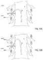
- FIG. 2Aillustrates an example positioning of the lead of FIG. 1A within a patient anatomy.
- FIG. 2Billustrates an example positioning of another embodiment of a lead of the present invention within a patient anatomy.
- FIG. 3illustrates another example positioning of the lead of FIG. 1A within a patient anatomy.
- FIG. 4illustrates an example positioning of a lead within a sacrum of a patient.
- FIG. 5Aillustrates an example positioning of a lead within a patient anatomy wherein the lead is advanced extraforaminally.
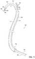
- FIG. 5Billustrates an example positioning of a lead having an elongated distal tip within a patient anatomy wherein the elongated distal tip is positioned within the spinal canal.
- FIGS. 6A-6Dillustrate one embodiment of a lead ( FIG. 6A ) and compatible delivery system 120 including a sheath 122 ( FIG. 6B ), stylet 124 ( FIG. 6C ) and introducing needle 126 ( FIG. 6D ).
- FIG. 7illustrates an embodiment of a sheath advanced over the shaft of the lead until a portion of its distal end abuts the distal tip of the lead.
- FIG. 8illustrates an embodiment of a stylet disposed within the lead, wherein extension of the lead and stylet through the sheath bends or directs the lead through a first curvature and extension of the lead and stylet beyond the distal end of the sheath allows the lead to bend further along a second curvature.
- FIGS. 9A-9Billustrate an embodiment of a method of delivering a lead to a position as illustrated as in FIG. 2A .
- FIGS. 10A-10Dillustrate an embodiment of a method of using multiple sheaths to deliver a lead to a position as illustrated in FIG. 2A .
- FIG. 11illustrates an embodiment of a delivery system for delivering two separate leads.
- FIGS. 12A-12Eillustrate an example method of delivering leads with the use of the delivery system of FIG. 11 .
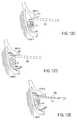
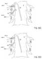
- FIG. 13illustrates another example positioning of the lead of FIG. 1 within a patient anatomy.
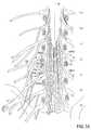
- FIG. 14an example positioning of the lead within the epidural space so as to stimulate target anatomies on opposite sides of the spinal column.
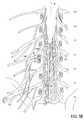
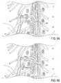
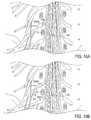
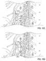
- FIGS. 15A-15Dillustrate an embodiment of a method of positioning a lead so as to stimulate target anatomies on two different spinal levels without exiting the epidural space or crossing the midline of the spinal canal.
- FIG. 1Aillustrates an embodiment of a stimulation system 10 of the present invention, wherein the system 10 includes a lead 100 , having at least one electrode 102 disposed thereon, and an implantable pulse generator (IPG) 112 .
- the lead 100comprises a shaft 103 having a proximal end 105 and a distal tip 106 .
- the proximal end 105is insertable into the IPG 112 to provide electrical connection to the lead 100 .
- the IPG 112contains a processor 114 , programmable stimulation information in memory 116 , as well as a power supply 118 , e.g., a battery, so that once programmed and turned on, the IPG 112 can operate independently of external hardware.
- the IPG 112is turned on and off and programmed to generate the desired stimulation pulses from an external programming device using transcutaneous electromagnetic or RF links.
- the stimulation informationincludes signal parameters such as voltage, current, pulse width, repetition rate, and burst rates.
- the at least one electrode 102includes one or more electrodes 102 disposed near the distal tip 106 and one or more electrodes 102 spaced at least a distance d from the distal tip 106 .
- the at least one electrode 102includes three electrodes disposed near the distal tip 106 (forming a first grouping A) and three electrodes disposed along the shaft 103 (forming a second grouping B).
- the first grouping A and second grouping Bare spaced apart by a distance d.
- the distance dis significantly greater than the distance between the electrodes within each grouping. In this embodiment, the distance d is measured from the approximate centers of each grouping.
- the distance dallows for the first grouping A of electrodes 102 to reside near a first target anatomy and the second grouping B of electrodes 102 to reside near a second target anatomy.
- the first target anatomyis a DRG on a first level and the second target anatomy is a DRG on a second level.
- the first and second levelsmay be adjacent to each other or may be spaced apart.
- the lead 100may be positioned in a variety of arrangements to align the groupings A, B with the DRGs, such as will be described and illustrated herein. Such arrangements allow simultaneous treatment of multiple targeted anatomies thereby reducing possible complications related to the placement of multiple devices, including reducing the amount of radiation exposure to the patient and minimizing the amount of time in the operating room due to the reduction in devices being placed. In addition, such arrangements provide improved anchoring which reduces migration of the lead yet allows for easy repositioning or removal of the lead if desired.
- the system 10may include any number of leads 100 , including one, two, three, four, five, six seven, eight or more leads 100 .
- each lead 100may include any number of electrodes 102 , including one, two, three, four, five, six or more electrodes 102 .
- each lead 100may include any number of electrode groupings.
- FIGS. 1B-1Eillustrate a sampling of lead 100 embodiments having different arrangements of electrode groupings.
- FIG. 1Billustrates the lead 100 embodiment of FIG. 1A
- the first grouping A and second grouping Bare spaced apart by a distance d which reflects the distance between target anatomies. In this embodiment, the distance d is measured from the approximate centers of each grouping.
- the distance dmay reflect the distance between the actual electrodes that are used to stimulate the target anatomies. For example, slight anatomical variations between patients may cause an electrode 102 near one end of group A and an electrode 102 near one end of group B to reside closest to their target anatomies. In such instances, the distance d may be measured between these electrodes. Thus, the distance d is generally measured as the distance between the target anatomies along the shaft 103 of the lead 100 and may include slight variations of endpoints within the groupings.
- FIG. 1Cillustrates an embodiment of a lead 100 having a first grouping A of electrodes 102 and second grouping B of electrodes 102 , wherein the groupings are spaced apart by a distance d as described above.
- the leadhas an elongated distal tip 106 having a length x.
- the elongated distal tipmay be used to anchor the lead 100 in a desired position.
- the length xis measured from the center of the first grouping A to the distal end of the distal tip 106 .
- the length xmay vary depending on the intended use of the lead 100 , as will be described and illustrated in later sections. However, it may be appreciated that, in some embodiments, the length x is approximately equal to the distance d. In other embodiments, the length x is longer than the distance d. It may be appreciated that the length x may optionally be shorter than the distance d.
- FIG. 1Dillustrates an embodiment of a lead 100 having a first grouping A of electrodes 102 and an elongated distal tip 106 having a length x. Again, the length x is measured from the center of the first grouping A to the distal end of the distal tip 106 . And, the length x may vary depending on the intended use of the lead 100 , as will be described and illustrated in later sections.
- FIG. 1Eillustrates an embodiment of a lead 100 having a first grouping A of electrodes 102 , a second grouping B of electrodes 102 and a third grouping C of electrodes 102 .
- the second grouping Bis spaced a distance y proximally the first grouping A
- the third grouping Cis spaced a distance z proximally to the second grouping B.
- the values for y and zmay vary depending on the intended use of the lead 100 , as will be described and illustrated in later sections. However, it may be appreciated that in some embodiments the distance y and/or distance z may be equal to the distance d, wherein the distance d is the distance between target anatomies, such as DRGs.
- distance y and distance z (y+z)may be equal to the distance d.
- grouping Amay reside near a target anatomy (such as a DRG 1 ) and grouping C may reside near another target anatomy (such as DRG 2 ), wherein the second grouping B resides therebetween to provide stimulation to a location such as a spinal cord S.
- each electrodeis individually programmed with stimulation information, such as voltage, current, pulse width, repetition rate, and burst rates. Thus, at least two of the electrodes may be programmed with different stimulation information.
- each grouping of electrodesis individually programmed with stimulation information, such as voltage, current, pulse width, repetition rate, and burst rates. Thus, at least two of the electrode groupings may be programmed with different stimulation information.
- the proximal end of the leadis insertable into a port in the IPG so that each electrode is provided an electrical signal via a contact within the port.
- the proximal end of the leadmay be connected with a Y connector which splits the lead into at least two halves. Each half is insertable into the IPG so that each electrode is provided an electrical signal via a contact within the port.
- Y connectorscan be used.
- a multi-pronged connectorcan be used to achieve this end.
- FIG. 2Aillustrates an example positioning of the lead 100 of FIG. 1A within a patient anatomy wherein the first grouping A of electrodes 102 resides near a first target anatomy and the second grouping B of electrodes 102 resides near a second target anatomy.
- the lumbar nerve rootsemerge from below the pedicle of their respective vertebrae.
- nerve root L 2resides below the pedicle of and at the lower half of the vertebral body of L 2 .
- the nerve rootsare described as being on levels.
- the L 2 nerve rootsare described to be on level L 2 .
- the first target anatomyis a DRG 1 on a first level (L 3 ) and the second target anatomy is a DRG 2 on a second level (L 2 ), wherein a pedicle P 1 resides between DRG 1 and DRG 2 .
- the lead 100is advanced within the epidural space of the spinal column or spinal canal S in an antegrade approach.
- the lead 100is directed laterally outward along the second level (L 2 ) toward the DRG 2 on one side of the spinal canal S.
- the distal tip 106 of the lead 100is advanced through the corresponding foramen and curves down around the pedicle P 1 , outside of the spinal canal S.
- the distal tip 106is further advanced back toward the spinal canal S, around the pedicle P 1 along the first level (L 3 ). Depending on the location of DRG 1 , the distal tip 106 may be advanced through the corresponding intervertebral (IV) foramen. In this embodiment, the distal tip 106 is positioned so that the first grouping A of electrodes 102 resides near DRG 1 and the second grouping B of electrodes 102 resides near DRG 2 .
- the distance dis equal to at least the anatomical distance of half of the diameter of the intervertebral foramen corresponding to DRG 1 , half of the circumference of pedicle P 1 and half of the diameter of the intervertebral foramen corresponding to DRG 2 .
- the distance dis in the range of at least approximately 45-50 mm, particularly at least approximately 48 mm.
- Anatomical differencessuch as due to degeneration, injury, gender and natural variation, may reduce distance d to the range of at least approximately 30-35 mm, particularly at least approximately 32 mm, or may increase the distance d to the range of at least approximately 60-65 mm, particularly at least approximately 64 mm.
- the distance dranges from at least approximately 30-65 mm. It may also be appreciated that in some embodiments, the distance d is greater than the anatomical distances calculated above, wherein any excess length simply resides within the anatomy (such as extending laterally outwardly) while the groupings of electrodes reside near their respective DRGs. Thus, distance d may optionally be greater than 65 mm.
- the lead 100is illustrated such that the electrode groupings A, B are disposed on the respective DRGs, however it may be appreciated that the groupings A, B may reside at various locations near or in the vicinity of the respective DRGs.
- the lead 100may be positioned against the pedicle P 1 at one or more locations.
- the lead 100may also be positioned against other pedicles or other anatomies, such as to assist in curving the lead 100 around pedicle P 1 .
- Positioning of the lead 100 as in FIG. 2Aallows for treatment of multiple targeted anatomies, DRG 1 and DRG 2 , with a single device.
- DRGs on two separate levelscan be stimulated with a single lead rather than two separate leads. This reduces possible complications related to the placement of multiple devices.
- DRG 1 and DRG 2can be simultaneously stimulated or stimulated separately at desired intervals.
- such positioningprovides improved anchoring. For example, the curvature of the lead 100 around the pedicle P 1 resists migration or pull-out of the lead 100 due to movement of the patient. However, the lead 100 can be withdrawn for removal or repositioning of the lead 100 .
- the embodiment of the lead 100 of FIG. 1Cmay be similarly positioned wherein the first grouping A of electrodes 102 resides near DRG 1 and the second grouping B of electrodes 102 resides near DRG 2 .
- the elongated distal tipwould extend further, such as into the spinal canal S, for additional anchoring.
- the distance dis equal to at least the anatomical distance of half of the diameter of the intervertebral foramen corresponding to DRG 1 , half of the circumference of pedicle P 1 and half of the diameter of the intervertebral foramen corresponding to DRG 2 , as described above.
- length x of the elongated distal tip 106is sufficiently long to provide desired anchoring.
- length xis equal to 1 ⁇ 2of a vertebral segment height or spinal level.
- the vertebral segment height or spinal levelis calculated as the sum of the height of a pedicle and the diameter of an intervertebral foraminal opening.
- An average pedicle height of approximately 18 mm and an average intervertebral foraminal opening of approximately 18 mmwould provide a vertebral segment height of 36 mm and a length x of approximately 18 mm.
- the pedicle height of approximately 13 mm and the intervertebral foraminal opening of approximately 13 mmwould provide a vertebral segment height of 26 mm and a length x of approximately 13 mm.
- the pedicle height of approximately 23 mm and the intervertebral foraminal opening of approximately 23 mmwould provide a vertebral segment height of 46 mm and a length x of approximately 23 mm.
- the length xis equal to one, two, three, four, five, six or more vertebral segment heights or spinal levels.
- the length xmay average approximately 36 mm, 72 mm, 108 mm, 144 mm, 180 mm, 216 mm or more. It may be appreciated that the length x may alternatively be more or less than incremental vertebral segment heights or spinal levels.
- FIG. 2Billustrates the embodiment of the lead 100 of FIG. 1D in a similar positioning.
- the first grouping Ais positioned near DRG 2 and the elongated distal tip 106 extends around the pedicle P 1 along the first level (L 3 ), as described above, and is used to anchor the lead 100 in position.
- the length xis approximately equal to the distance d.
- the length xmay be equal to at least the anatomical distance of half of the diameter of the intervertebral foramen corresponding to DRG 1 , half of the circumference of pedicle P 1 and half of the diameter of the intervertebral foramen corresponding to DRG 2 , as described in relation to distance d above.
- the distal tip 106extends further, such as into the spinal canal S, for additional anchoring.
- the length xis longer than the distance d.
- the length xis longer than distance d by 1 ⁇ 2, one, two, three, four, five, six or more vertebral segment heights or spinal levels.
- the lead 100may be positioned in a similar manner with a retrograde approach. In such an approach, the lead 100 is directed laterally outward toward the DRG 1 on one side of the spinal canal S. The distal tip 106 of the lead 100 is advanced and curves up around the pedicle P 1 , outside of the spinal canal S. The distal tip 106 is further advanced back toward the spinal canal S, around the pedicle P 1 toward DRG 2 . It may also be appreciated that the lead 100 may be positioned by entering the spinal canal with a contralateral or ipsilateral approach. Such entrance points may be on the same level as one of the target DRGs.
- FIG. 3illustrates another example positioning of the lead 100 of FIG. 1 A within a patient anatomy wherein the first grouping A of electrodes 102 resides near a first target anatomy and the second grouping B of electrodes 102 resides near a second target anatomy.
- the first target anatomyis a DRG 1 on a first level (L 3 ) and the second target anatomy is a DRG 3 on a third level (L 1 ), wherein pedicle P 1 , DRG 2 and pedicle P 2 resides between DRG 1 and DRG 3 .
- the DRGsare stimulated on levels that are not adjacent to each other, and DRG 2 on the second level (L 2 ) is not directly stimulated.
- the lead 100is advanced within the epidural space of the spinal canal S in an antegrade approach.
- the lead 100is directed laterally outward along the third level (L 1 ) toward the DRG 3 on one side of the spinal canal S.
- the distal tip 106 of the lead 100is advanced through the corresponding intervertebral foramen and curves down around the pedicle P 2 , outside of the spinal canal S.
- the distal tip 106is further advanced in a retrograde manner outside of the spinal canal S, bypassing DRG 2 .
- the distal tip 106is further advanced back toward the spinal canal S, around the pedicle P 1 and toward DRG 1 along the first level (L 3 ). Depending on the location of DRG 1 , the distal tip 106 may also pass through the corresponding intervertebral foramen. In this embodiment, the distal tip 106 is positioned so that the first grouping A of electrodes 102 resides near DRG 1 and the second grouping B of electrodes 102 resides near DRG 3 .
- the distance dis equal to at least the anatomical distance of half of the diameter of the intervertebral foramen corresponding to DRG 1 , half of the circumference of pedicle P 1 , the diameter of the intervertebral foramen corresponding to DRG 2 , half the circumference of pedicle P 2 , and half of the diameter of the intervertebral foramen corresponding to DRG 3 .
- the distance dis in the range of approximately 80-90 mm, particularly approximately 84 mm.
- Anatomical differencessuch as due to degeneration, injury, gender and natural variation, may reduce distance d to the range of approximately 50-65 mm, particularly approximately 58 mm, or may increase the distance d to the range of approximately 100-120 mm, particularly approximately 110 mm. Therefore, in some embodiments, the distance d ranges from approximately 50-110 mm.
- the lead 100is illustrated such that the electrode groupings A, B are disposed on the respective DRGs, however it may be appreciated that the groupings A, B may reside at various locations near or in the vicinity of the respective DRGs.
- the lead 100may be positioned against the pedicles P 1 , P 2 at one or more locations.
- the lead 100may also be positioned against other pedicles or other anatomies, such as to assist in curving the lead 100 around the pedicles P 1 , P 2 .
- the lead 100 embodiments of FIG. 1C and FIG. 1Dmay be similarly positioned. It may also be appreciated that the lead 100 may be positioned so as to stimulate DRGs on non-adjacent levels in a similar manner with a retrograde approach. In such an approach, the lead 100 is directed laterally outward along the third level (L 3 ) toward the DRG 1 on one side of the spinal canal S. The distal tip 106 of the lead 100 is advanced beyond curves up around the pedicle P 1 , outside of the spinal canal S. The distal tip 106 is further advanced in an antegrade manner outside of the spinal canal S, bypassing DRG 2 . The distal tip 106 is further advanced back toward the spinal canal S, around the pedicle P 2 and along the first level (L 1 ).
- FIG. 4illustrates an example positioning of the lead 100 within a sacrum SA of a patient.
- the sacrum SAis a large, triangular bone near the base of the spinal canal S, where it is inserted like a wedge between the two pelvic or hip bones H. Its upper part connects with the last lumbar vertebra L 5 , and bottom part with the coccyx C.
- the DRGs in the sacral regionare disposed on dorsal roots which extend laterally outwardly at a steeper angle and may be found in a different location than the DRGs in the cervical, thoracic and lumbar regions.
- the DRGs in the sacral regionare located either inside the spinal canal or intraforaminally.
- the S 1 DRGapproximately 55-60% are located in the foramen and 40-45% are located in the canal.
- S 2 DRGit is varied with more DRGs located inside the canal.
- all S 3 and S 4 DRGsare located within the canal.
- FIG. 4illustrates an anatomy wherein each of the DRGs (at levels S 1 , S 2 , S 3 , S 4 ) is located within the canal.
- the lead 100is advanced through the sacral hiatus SH, the opening into the vertebral canal in the midline of the dorsal surface of the sacrum between the laminae of the fifth sacral vertebra, in an antegrade direction.
- the lead 100is positioned so that the first grouping A of electrodes 102 resides near a first target anatomy and the second grouping B of electrodes 102 resides near a second target anatomy.
- the first target anatomyis a DRG 1 on a first level (S 2 ) and the second target anatomy is a DRG 2 on a second level (S 2 ).
- the lead 100is advanced within the epidural space of the spinal canal S and is directed laterally outward along the second level (S 1 ) toward the DRG 2 on one side of the spinal canal S.
- the distal tip 106 of the lead 100is advanced beyond the DRG 2 (through the corresponding foramen) and curves down along the sacrum SA, outside of the sacrum SA.
- the distal tip 106is further advanced back toward the spinal canal S and into an adjacent foramen leading to DRG 1 along the first level (S 2 ).
- the distal tip 106is positioned so that the first grouping A of electrodes 102 resides near DRG 1 and the second grouping B of electrodes 102 resides near DRG 2 .
- the distance dis equal to at least the anatomical distance of between the sacral foramen.
- the distance dis in the range of approximately 30-35 mm, particularly approximately 32 mm.
- Anatomical differencessuch as due to degeneration, injury, gender and natural variation, may reduce distance d to the range of approximately 22-28 mm, particularly approximately 25 mm, or may increase the distance d to the range of approximately 38-50 mm, particularly approximately 42 mm. Therefore, in some embodiments, the distance d ranges from approximately 22-50 mm.
- the lead 100is illustrated such that the electrode groupings A, B are disposed on the respective DRGs, however it may be appreciated that the groupings A, B may reside at various locations near or in the vicinity of the respective DRGs.
- Positioning of the lead 100 as in FIG. 4has some particular advantages to stimulating the sacral region.
- Stimulation of the sacral regionis used to treat pain but also to treat a variety of other pelvic floor disorders.
- Pelvic floor disordersinclude urinary incontinence, constipation, rectal pain, vaginal and/or rectal prolapse, pelvic pain/trauma, and sexual dysfunction (Dyspareunia, Apareunia).
- Previous surgical methods to implant a neurostimulation lead in a patient's sacrum to treat pelvic floor disordershave been invasive by requiring a large sacral incision in a procedure known as dissection. Dissection involves making a midline incision over the sacrum from below S 4 up to S 1 .
- the paraspinal muscle fibersare split and sharply retracted.
- the sacral foramenare then exposed.
- another small incisionis made over the desired foramen that is large enough to allow insertion of the stimulation lead.
- the stimulation leadis inserted through the incision. Surgically implanting the stimulation lead in this manner can cause patient complications, create significant patient recovery time and create a significant expense to the healthcare system.
- anchoring of the leadis typically achieved by suturing to tissue surrounding the sacrum. That tissue, however, is relatively weak and only one or two sutures may be placed through it. Even then the fixation of the lead is less than wholly reliable.
- the leadmay move from the optimal site. Movement of the lead, whether over time from suture release or during implantation, has undesired effects. For example, unintended movement of an object positioned proximate a nerve may cause unintended nerve damage.
- reliable stimulation of a nerverequires consistent nerve response to the electrical stimulation which, in turn, requires consistent presence of the electrode portion of the lead proximate the nerve.
- more reliable anchoringhas been attempted by attaching the lead to the sacrum itself with the use of bone screws. Among other complications, such anchoring is typically invasive, difficult to achieve and even more difficult to reverse for removal of the lead.
- Positioning of the lead 100 of the present invention in a manner such as illustrated in FIG. 4is minimally invasive and provides ease of placement, anchoring and removal.
- the curvature of the lead 100 through one foramen and into another foramenresists migration or pull-out of the lead 100 .
- the lead 100can be easily withdrawn for removal or repositioning of the lead 100 since it is not sutured or screwed in place.
- the lead 100may be positioned within the sacrum SA in a manner similar to FIG. 4 wherein DRGs are stimulated on levels that are not adjacent to each other.
- the lead 100is advanced within the epidural space of the spinal canal S and is directed laterally outward along the second level (S 1 ) toward the DRG 2 on one side of the spinal canal S.
- the distal tip 106 of the lead 100is advanced beyond the DRG 2 (through the corresponding foramen) and curves down along the sacrum SA, outside of the spinal canal S.
- the distal tip 106is further advanced back toward the spinal canal S and into a non-adjacent foramen leading to DRG 1 along the first level (S 3 ).
- the DRG at level S 2is skipped over and not stimulated. Skipping one or more levels may be desirable due to ascending and descending pain pathways between spinal levels which may allow therapeutic benefit to a spinal level which is not directly stimulated.
- the distance dis at least the distance between the foramen that are entered. For example, when one level is skipped, the distance d is equal to at least twice the average anatomical distance between sacral foramen. In some instances, the distance d is in the range of approximately 60-70 mm, particularly approximately 64 mm. When two levels are skipped, the distance d is equal to at least three times the average anatomical distance between sacral foramen.
- the distance dis in the range of approximately 80-100 mm, particularly approximately 96 mm.
- the DRGsare stimulated in both the sacrum and above the sacrum.
- the lead 100may be positioned so that the first grouping A of electrodes 102 resides near a DRG on level S 1 and the second grouping B of electrodes 102 resides near a DRG on level L 5 .
- the distance dis at least the distance between the associated foramen.
- the lead 100may be positioned within the sacrum SA so as to stimulate DRGs on adjacent or non-adjacent levels in a similar manner with a retrograde approach.
- the lead 100is inserted above the sacrum SA and advanced downward into the sacral region.
- the lead 100is advanced within the epidural space of the spinal canal S and is directed laterally outward toward DRG 1 on one side of the spinal canal S.
- the distal tip 106 of the lead 100is advanced beyond the DRG 1 (through the corresponding foramen) and curves up along the sacrum SA, outside of the sacrum SA.
- the distal tip 106is further advanced back toward the spinal canal S and into an adjacent foramen leading to DRG 2 .
- the lead 100 embodiments of FIG. 1C and FIG. 1Dmay be similarly positioned (antegrade, retrograde, adjacent levels, non-adjacent levels, etc.
- the distal tip 106extends further into the sacrum SA or up into the spinal canal S for additional anchoring.
- the length x of the elongated distal tip 106is in the range of approximately 1 ⁇ 2, one, two, three, four, five, six or more vertebral segment heights or spinal levels.
- FIG. 5Aillustrates another example positioning of the lead 100 of the present invention within a patient anatomy wherein the first grouping A of electrodes 102 resides near a first target anatomy and the second grouping B of electrodes 102 resides near a second target anatomy.
- the first target anatomyis a DRG 1 on a first level (L 3 ) and the second target anatomy is a DRG 2 on a second level (L 2 ), wherein a pedicle P 1 resides between DRG 1 and DRG 2 .
- the lead 100is advanced extraforaminally, or from an “outside- in” approach, such as along a peripheral nerve P, transverse process or other bony structure, toward a DRG and a spinal canal S.
- the distal tip 106 of the lead 100is advanced toward DRG 2 and through the corresponding intervertebral foramen along the second level (L 2 ) and curves down around the pedicle P 1 along the spinal canal S, within the epidural space.
- the distal tip 106is further advanced away from the spinal canal S, toward DRG 1 along the first level (L 3 ) (and may pass through the corresponding intervertebral foramen depending on the location of DRG 1 ).
- the distal tip 106is positioned so that the first grouping A of electrodes 102 resides near DRG 1 and the second grouping B of electrodes 102 resides near DRG 2 .
- the distance dis equal to at least the anatomical distance of half of the diameter of the intervertebral foramen corresponding to DRG 1 , half of the circumference of pedicle P 1 and half of the diameter of the intervertebral foramen corresponding to DRG 2 .
- Thismay be calculated as the average diameter of an intervertebral foraminal opening (approximately 13-22 mm, typically approximately 18 mm) plus the average pedicle height (approximately 13-24 mm, typically approximately 18 mm) plus the average pedicle width (approximately 6-18 mm, typically approximately 12 mm).
- the distance dis in the range of approximately 45-50 mm, particularly approximately 48 mm.
- Anatomical differencessuch as due to degeneration, injury, gender and natural variation, may reduce distance d to the range of approximately 30-35 mm, particularly approximately 32 mm, or may increase the distance d to the range of approximately 60-65 mm, particularly approximately 64 mm. Therefore, in some embodiments, the distance d ranges from approximately 30-65 mm.
- the lead 100is illustrated such that the electrode groupings A, B are disposed near the respective DRGs, however it may be appreciated that the groupings A, B may reside at various locations on or in the vicinity of the respective DRGs.
- the lead 100may be positioned against the pedicle P 1 at one or more locations.
- the lead 100may also be positioned against other pedicles or other anatomies, such as to assist in curving the lead 100 around the pedicles P 1 .
- the distal tip 106may be advanced further down the spinal canal S and then advanced away from the spinal canal S toward a non-adjacent DRG so as to stimulate multiple non-adjacent levels.
- the lead 100may be positioned so as to curve up through the spinal canal S and advance away from the spinal canal along an adjacent or non-adjacent level thereabove. Still further, it may be appreciated that the lead 100 may pass through the epidural space and across the midline M of the spinal canal S to wrap around a pedicle P 1 ′ on the opposite side.
- the lead 100is advanced extraforaminally, or from an “outside-in” approach, such as along a peripheral nerve P, transverse process or other bony structure, toward DRG 2 and the spinal canal S.
- the distal tip 106 of the lead 100is advanced toward DRG 2 and through the corresponding intervertebral foramen along the second level (L 2 ) and crosses the midline M of the spinal canal S.
- the distal tip 106then advances toward DRG 2 ′ and passes through the associated intervertebral foramen.
- the distal tip 106then curves down around the pedicle P 1 ′ and toward DRG 1 ′ along the first level (L 3 ) (and may pass through the corresponding intervertebral foramen depending on the location of DRG 1 ′).
- the distal tip 106is positioned so that the first grouping A of electrodes 102 resides near DRG 1 ′ and the second grouping B of electrodes 102 resides near DRG 2 ′.
- a lead 100 embodiment as in FIG. 1Dis shown similarly positioned.
- the grouping A of electrodes 102resides near a target anatomy (DRG) and the elongated distal tip 106 extends into the spinal canal S.
- DRGtarget anatomy
- the distal tip 106extends in a retrograde direction, however it may be appreciated that the distal tip 106 may extend in an antegrade direction. In either instance, the distal tip 106 extends sufficient distance to provide anchoring.
- the length xis approximately equal to the distance of one half of a spinal level (approximately 26 mm), one spinal level (approximately 48 mm), two spinal levels (approximately 58 mm), three spinal levels (approximately 78 mm), four spinal levels (approximately 104 mm), or more. It may also be appreciated that the elongated distal tip 106 may cross the midline M of the spinal canal S and pass partially through an intervertebral foramen or wrap around a pedicle P 1 ′ on the opposite side.
- the methods and devices of FIG. 5A and FIG. 5Bmay also be applied to the sacrum SA.
- the lead 100is advanced extraforaminally, or from an “outside-in” approach, toward a DRG and a spinal canal S.
- the distal tip 106 of the lead 100is advanced toward DRG 2 and through the corresponding foramen along the second level (S 1 ).
- the distal tip 106curves down around within the sacrum SA toward the DRG 1 along the first level (S 2 ) and may optionally pass through the corresponding foramen.
- the elongated distal tip 106may extends and reside within the sacrum S for anchoring. Or, the elongated distal tip 106 may curve around within the sacrum towards or within another foramen.
- FIGS. 6A-6Dillustrate one embodiment of a lead 100 ( FIG. 6A ) and compatible delivery system 120 including a sheath 122 ( FIG. 6B ), stylet 124 ( FIG. 6C ) and introducing needle 126 ( FIG. 6D ).
- the lead 100comprises a shaft 103 having three electrodes 102 disposed near the distal tip 106 (forming a first grouping A) and three electrodes 102 disposed along the shaft 103 at least a distance d from the distal tip 106 (forming a second grouping B).
- the lead 100has a closed-end distal tip 106 .
- the distal tip 106may have a variety of shapes including a rounded shape, such as a ball shape (shown) or tear drop shape, and a cone shape, to name a few. These shapes provide an atraumatic tip for the lead 100 as well as serving other purposes.
- the lead 100also includes a stylet lumen 104 which extends toward the closed-end distal tip 106 .
- FIG. 6Billustrates an embodiment of a sheath 122 of the present invention.
- the sheath 122has a distal end 128 which is pre-curved to have an angle ⁇ , wherein the angle ⁇ is in the range of approximately 80 to 165 degrees.
- the sheath 122is sized and configured to be advanced over the shaft 103 of the lead 100 until a portion of its distal end 128 abuts the distal tip 106 of the lead 100 , as illustrated in FIG. 7 .
- the ball shaped tip 106 of this embodimentalso prevents the sheath 122 from extending thereover. Passage of the sheath 122 over the lead 100 causes the lead 100 to bend in accordance with the precurvature of the sheath 122 .
- the sheath 122assists in steering the lead 100 along the spinal canal S and toward a target DRG, such as in a lateral direction.
- the sheath 122assists in steering the lead 100 through the sacrum SA and toward a target DRG, such as in a lateral direction.
- the sheath 122assists in steering the lead 100 along the peripheral nerves P and toward the spinal canal S, around the pedicle P 1 .
- the stylet 124has a distal end 130 which is pre-curved so that its radius of curvature is in the range of approximately 0.1 to 0.5 inches.
- the stylet 124is sized and configured to be advanced within the stylet lumen 104 of the lead 100 .
- the stylet 124extends therethrough so that its distal end 130 aligns with the distal end 101 of the lead 100 . Passage of the stylet 124 through the lead 100 causes the lead 100 to bend in accordance with the precurvature of the stylet 124 .
- the stylet 124has a smaller radius of curvature, or a tighter bend, than the sheath 122 .
- extension of the lead 100 and stylet 124 through the sheath 122bends or directs the lead 100 through a first curvature 123 .
- Further extension of the lead 100 and stylet 124 beyond the distal end 128 of the sheath 122allows the lead 100 to bend further along a second curvature 125 . This allows the lead 100 to make sharp turns and extended curvatures, such as around one or more pedicles.
- FIGS. 9A-9Billustrate an embodiment of the lead 100 and delivery system 120 of FIGS. 6A-6D used in positioning the lead 100 as in FIG. 2A .
- the sheath 122is advanced over the shaft 103 of the lead 100 . Passage of the sheath 122 over the lead 100 causes the lead 100 to bend in accordance with the precurvature of the sheath 122 .
- the sheath 122assists in steering the lead 100 along the spinal canal S and in a lateral direction toward a target DRG 2 .
- FIG. 9Aillustrates the sheath 122 positioned so as to direct the lead 100 toward the target DRG 2 , and the lead 100 is shown advanced beyond the distal end of the sheath 122 .
- FIG. 9Aillustrates the sheath 122 positioned so as to direct the lead 100 toward the target DRG 2 , and the lead 100 is shown advanced beyond the distal end of the sheath 122 .
- FIG. 9Billustrates the lead 100 advanced further beyond the distal end of the sheath 122 .
- the stylet 124which is pre-curved and causes the lead 100 to bend in accordance with the precurvature of the stylet 124 . This bending guides the lead 100 around the pedicle P 1 and directs the distal end of the lead 100 toward the target DRG 1 .
- the lead 100may be further advanced to desirably position the first grouping A of electrodes 102 near DRG 1 and the second grouping B of electrodes 102 resides near DRG 2 .
- the stylet 124 and sheath 122are then removed and the lead 100 left in place.
- the lead 100does not require stiff or torqueable construction since the lead 100 is not torqued or steered by itself.
- the lead 100is positioned with the use of the sheath 122 and stylet 124 which direct the lead 100 through the two step curvature. This eliminates the need for the operator to torque the lead 100 and optionally the sheath 122 with multiple hands. This also allows the lead 100 to have a lower profile as well as a very soft and flexible construction. This, in turn, minimizes erosion and discomfort created by pressure on nerve tissue, such as the target DRG and/or the nerve root, once the lead 100 is implanted. For example, such a soft and flexible lead 100 will minimize the amount of force translated to the lead 100 by body movement (e.g. flexion, extension, torsion).
- an embodiment of an introducing needle 126is illustrated.
- the introducing needle 126is used to access the epidural space of the spinal cord S.
- the needle 126has a hollow shaft 127 and typically has a very slightly curved distal end 132 .
- the shaft 127is sized to allow passage of the lead 100 , sheath 122 and stylet 124 therethrough.
- the needle 126is 14 gauge which is consistent with the size of epidural needles used to place conventional percutaneous leads within the epidural space. However, it may be appreciated that other sized needles may also be used, particularly smaller needles such as 16-18 gauge.
- the needle 126also typically includes a Luer-LokTM fitting 134 or other fitting near its proximal end.
- the Luer-LokTM fitting 134is a female fitting having a tabbed hub which engages threads in a sleeve on a male fitting, such as a syringe.
- Example leads, delivery systems and methods of approaching a target DRG using the delivery system 120 and other delivery systemsare further described and illustrated in U.S. Provisional Patent Application No. 61/144,690 filed Jan. 14, 2009, and U.S. Non-Provisional patent application Ser. No. 12/687,737 filed Jan. 14, 2010, both incorporated herein by reference for all purposes.
- multiple sheathsmay be used to desirably direct the lead 100 into its desired position.
- an additional sheathmay be used with the above described delivery system 120 . In such situations, the additional sheath is advanceable through sheath 122 , and the lead 100 is advanceable through the additional sheath.
- the additional sheathmay be straight or may have any desired curvature.
- the additional sheathmay be curved to direct a lead 100 around a pedicle.
- the additional sheathhas a stiffness that allows for directing a relatively floppy lead.
- a stiffer leadmay be used to provide directional control.
- FIGS. 10A-10Dillustrate an embodiment of the lead 100 and delivery system 120 of FIGS. 6A-6D , with the addition of an additional sheath 122 ′, used in positioning the lead 100 as in FIG. 2A .
- the multiple sheaths, sheath 122 and sheath 122 ′ (disposed therein)is advanced over the shaft 103 of the lead 100 and positioned so as to direct the lead 100 toward a target DRG 2 .
- the pre-curvature of the sheathscauses the lead 100 to bend, as in a lateral direction toward DRG 2 .
- FIG. 10Billustrates the additional sheath 122 ′ advanced beyond the distal end of the sheath 122 .
- FIG. 10Cillustrates the lead 100 advanced beyond the distal end of the additional sheath 122 ′.
- the stylet 124which is pre-curved and causes the lead 100 to bend in accordance with the precurvature of the stylet 124 . This bending guides the lead 100 further around the pedicle P 1 and directs the distal end of the lead 100 toward the target DRG 1 .
- the lead 100may be further advanced to desirably position the first grouping A of electrodes 102 near DRG 1 and the second grouping B of electrodes 102 resides near DRG 2 .
- sheaths 122 , 122 ′are then removed and the lead 100 left in place, as illustrated in FIG. 10D . It may be appreciated that various sub-combinations of delivery tools may alternatively be used, such as multiple sheaths without a stylet.
- the leadmay have a pre-curved shape wherein the lead is deliverable through a sheath having a straighter shape, such as a substantially straight shape or a curved shape which is has a larger radius of curvature than the lead. Advancement of the lead out of the sheath allows the lead to recoil toward its pre-curved shape. Various combinations of curvature between the lead and sheath may allow for a variety of primary and secondary curvatures.
- FIG. 11illustrates an embodiment of a delivery system 200 used for such a delivery.
- the delivery system 200includes a delivery device 202 and an introducer 204 .
- the delivery device 202comprises a shaft 206 having a proximal end 208 and a distal tip 210 .
- the shaft 206includes a first lumen 212 extending from the proximal end 208 to or near the distal tip 210 .
- a first lead 300 having at least one electrode 302 disposed near its distal end 304is advanceable through the first lumen 212 , as shown, so that the at least one electrode 302 is advanceable beyond the distal tip 210 of the delivery device 202 .
- the shaft 206also includes a second lumen 216 extending from the proximal end 208 to a port 218 disposed along the shaft 206 .
- a second lead 306 having at least one electrode 303 disposed near its distal end 308is advanceable through the second lumen 216 , as shown, so that the at least one electrode 303 is advanceable through the port 218 .
- the port 218is disposed a distance d′ from the distal tip 210 .
- the distance d′allows for the first lead 300 to be delivered so that the at least one electrode 302 is positioned near a first target anatomy and allows for the second lead 306 to be delivered so that the at least one electrode 303 is disposed near a second target anatomy.
- the distance d′may be equal to the distance d in the above described embodiments.
- the shaft 206is shaped, such as curved, so as to direct the leads 300 , 306 in desired directions, such as opposite directions.
- the introducer 204is typically comprised of a material which provides enough rigidity to sufficiently straighten the shaped portion of the shaft 206 upon advancement of the introducer 204 over the shaft 206 .
- the introducer 204comprises a needle. In other embodiments, the introducer 204 comprises a sheath.
- FIGS. 12A-12Eillustrate an example method of delivering the leads 300 , 306 with the use of the delivery system 200 .
- the first target anatomycomprises DRG 1 on a first level and the second target anatomy comprises DRG 2 on a second level, wherein a pedicle P 1 resides therebetween.
- the system 200is advanced toward DRG 2 , above the pedicle P 1 .
- the system 200is configured so that the introducer 204 is advanced over the delivery device 202 which causes the device 202 to form a straightened configuration therein.
- FIG. 12Ba portion of the device 202 is then advanced beyond the introducer 204 .
- the device 202resumes its curved shape which directs the distal tip 210 of the device 202 around the pedicle P 1 , toward DRG 1 .
- the introducer 204is then removed and the device 202 is left in place.
- the device 202is positioned so that the distal tip 210 is directed toward the first target anatomy (DRG 1 ) and the port 218 is directed toward the second target anatomy (DRG 2 ).
- lead 300is advanced through the first lumen 212 so that one or more of the at least one electrode 302 emerges from the distal tip 210 .
- the lead 300is further advanced until the at least one electrode 302 is desirably positioned in relation to DRG 1 .
- lead 306is advanced through the second lumen 216 so that one or more of the at least one electrode 303 emerges from the port 218 .
- the lead 306is further advanced until the at least one electrode 303 is desirably positioned in relation to DRG 2 . Referring to FIG. 12E , the delivery device 202 is then retracted leaving the leads 300 , 306 in place.
- FIG. 13illustrates another example positioning of the lead 100 of FIG. 1 within a patient anatomy wherein the first grouping A of electrodes 102 resides near a first target anatomy and the second grouping B of electrodes 102 resides near a second target anatomy.
- the first target anatomyis a DRG 1 on a first level (T 12 ) and the second target anatomy is a DRG 2 on the same level (T 12 ).
- the lead 100is advanced extraforaminally, or from an “outside-in” approach along a peripheral nerve P toward a DRG and a spinal canal S.
- the distal tip 106 of the lead 100is advanced toward DRG 2 and through the corresponding intervertebral foramen along the first level (T 12 ).
- the distal tip 106is further advanced across the midline M or the spinal canal S toward DRG 1 along the same level (T 12 ) (and may pass through the corresponding intervertebral foramen depending on the location of DRG 1 ).
- the distal tip 106is positioned so that the first grouping A of electrodes 102 resides near DRG 1 and the second grouping B of electrodes 102 resides near DRG 2 .
- the lead 100is illustrated such that the electrode groupings A, B are disposed on the respective DRGs, however it may be appreciated that the groupings A, B may reside at various locations on or in the vicinity of the respective DRGs.
- the lead 100may be positioned against the pedicles P 1 , P 1 ′ at one or more locations. It may also be appreciated that the lead 100 may be positioned anterior or posterior to the dura mater within the spinal canal S.
- the lead 100may be similarly positioned to stimulate target anatomies on opposite sides of the spinal column and on differing levels.
- the first target anatomyis a DRG 1 on a first level (T 12 ) and the second target anatomy is a DRG 3 on an adjacent level (L 1 ).
- the first target anatomyis a DRG 1 on a first level (T 12 ) and the second target anatomy is a DRG 4 on an non-adjacent level (L 2 ).
- the lead 100is steered with the use of a delivery system, such as described above.
- FIG. 14illustrates another example positioning of the lead 100 so as to stimulate target anatomies on opposite sides of the spinal canal and optionally on differing levels.
- the first target anatomyis a DRG 1 on a first level and the second target anatomy is a DRG 2 on the same level.
- the lead 100is advanced epidurally, in an antegrade direction, along the spinal canal S.
- the distal tipis positioned so that the first grouping A of electrodes 102 resides near DRG 1 , such as with the use of the delivery system 120 described above.
- the lead 100is then extended across the midline M of the spinal canal S on the same spinal level, and the second grouping B of electrodes 102 is positioned near the second target anatomy DRG 2 .
- a single leadis able to stimulate two different target anatomies on the same spinal level.
- the lead 100may similarly be positioned so as to stimulate target anatomies on different spinal levels.
- the lead 100extends across the midline M of the spinal canal S to a different spinal level, and the second grouping B of electrodes 102 is positioned near a target anatomy such as DRG 3 or DRG 4 .
- the leadmay be positioned in a variety of configurations, such zig-zagging across the spinal canal S to stimulate target anatomies on a variety of levels and/or on the same or opposite sides of the spinal canal S, and the electrodes may be disposed at any location along the lead to correspond to such positioning.
- the leadmay be positioned using any suitable approach, including a retrograde, contralateral, ipsilateral or extraforaminal approach, to name a few.
- FIGS. 15A-15Dillustrates another example positioning of the lead 100 of FIG. 1 within a patient anatomy wherein the first grouping A of electrodes 102 resides near a first target anatomy and the second grouping B of electrodes 102 resides near a second target anatomy.
- the first target anatomyis DRG 1 on a first level
- the second target anatomyis DRG 2 on an adjacent, second level.
- the first grouping A of electrodes 102is positioned near the first target anatomy DRG 1 with the use of the delivery system 120 described above.
- the sheath 122is advanced over the lead 100 and assists in directing the lead 100 laterally outwardly, toward DRG 1 , along with the assistance of the stylet 124 within the lead 100 .
- the stylet 124is then retracted and the sheath 122 is advanced along the spinal canal S while the distal end of the lead 100 remains in place, as illustrated in FIG. 15B .
- the lead 100wraps at least partially around an internal border of the pedicle P within the epidural space.
- the sheath 122is manipulated so as to direct the lead 100 toward the second target anatomy DRG 2 , as illustrated in FIG. 15C .
- the stylet 124may also be advanced to assist in directing the lead 100 toward the second target anatomy DRG 2 and desirably positioning the second grouping of electrodes 102 near DRG 2 .
- a single leadis able to stimulate target anatomies on two different spinal levels without exiting the epidural space or crossing the midline of the spinal canal S.
- the leadmay be positioned using any suitable approach, including a retrograde, contralateral, ipsilateral or extraforaminal approach, to name a few.
- the methods, devices and systems described hereinmay be used to stimulate a variety of target anatomies throughout the body.
- the first grouping A of electrodes 102resides along the spinal cord, such as along the midline of the spinal cord, and the second grouping of electrodes resides near a DRG.
- the second grouping of electrodesresides along a dorsal root.
- the second grouping of electrodesresides along a dorsal root entry zone (DREZ).
- DREZdorsal root entry zone
- the second grouping of electrodesresides along a different portion of the spinal cord, such as an area off-set from the midline.
- various types and/or locations of spinal tissueare able to be stimulated with a single lead. This may be desired when the patient is not able to obtain adequate pain relief by stimulating one anatomical area wherein stimulation of an additional area is needed.
- patients having leg radiculopathy and axial back painmay desire dorsal column stimulation to achieve pain relief in the legs and DRG stimulation to achieve pain relief of the back.
- Such stimulationmay be achieved with the use of a single lead utilizing the methods, devices and systems of the present invention.
- a variety of pain-related conditionsare treatable with the systems, methods and devices of the present invention.
- the following conditionsmay be treated:
Landscapes
- Health & Medical Sciences (AREA)
- Life Sciences & Earth Sciences (AREA)
- General Health & Medical Sciences (AREA)
- Neurosurgery (AREA)
- Engineering & Computer Science (AREA)
- Biomedical Technology (AREA)
- Nuclear Medicine, Radiotherapy & Molecular Imaging (AREA)
- Neurology (AREA)
- Radiology & Medical Imaging (AREA)
- Animal Behavior & Ethology (AREA)
- Veterinary Medicine (AREA)
- Public Health (AREA)
- Pain & Pain Management (AREA)
- Orthopedic Medicine & Surgery (AREA)
- Cardiology (AREA)
- Heart & Thoracic Surgery (AREA)
- Electrotherapy Devices (AREA)
Abstract
Description
- 1) Failed Back Surgery syndrome
- 2) Chronic Intractable Low Back Pain due to:
- 4) Complex Regional Pain Syndrome
- 5) Post-Herpetic Neuralgia
- 6) Diabetic Neuropathic Pain
- 7) Intractable Painful Peripheral Vascular Disease
- 8) Raynaud's Phenomenon
- 9) Phantom Limb Pain
- 10) Generalized Deafferentation Pain Conditions
- 11) Chronic, Intractable Angina
- 12) Cervicogenic Headache
- 13) Various Visceral Pains (pancreatitis, etc.)
- 14) Post-Mastectomy Pain
- 15) Vulvodynia
- 16) Orchodynia
- 17) Painful Autoimmune Disorders
- 18) Post-Stroke Pain with limited painful distribution
- 19) Repeated, localized sickle cell crisis
- 20) Lumbar Radiculopathy
- 21) Thoracic Radiculopathy
- 22) Cervical Radiculopathy
- 23) Cervical axial neck pain, “whiplash”
- 24) Multiple Sclerosis with limited pain distribution
- 1) Parkinson's Disease
- 2) Multiple Sclerosis
- 3) Demylenating Movement Disorders
- 4) Physical and Occupational Therapy Assisted Neurostimulation
- 5) Spinal Cord Injury—Neuroregeneration Assisted Therapy
- 6) Asthma
- 7) Chronic Heart Failure
- 8) Obesity
- 9) Stroke—such as Acute Ischemia
Claims (6)
Priority Applications (1)
| Application Number | Priority Date | Filing Date | Title |
|---|---|---|---|
| US12/780,696US9259569B2 (en) | 2009-05-15 | 2010-05-14 | Methods, systems and devices for neuromodulating spinal anatomy |
Applications Claiming Priority (2)
| Application Number | Priority Date | Filing Date | Title |
|---|---|---|---|
| US17884709P | 2009-05-15 | 2009-05-15 | |
| US12/780,696US9259569B2 (en) | 2009-05-15 | 2010-05-14 | Methods, systems and devices for neuromodulating spinal anatomy |
Publications (2)
| Publication Number | Publication Date |
|---|---|
| US20100292769A1 US20100292769A1 (en) | 2010-11-18 |
| US9259569B2true US9259569B2 (en) | 2016-02-16 |
Family
ID=43069150
Family Applications (1)
| Application Number | Title | Priority Date | Filing Date |
|---|---|---|---|
| US12/780,696Active2030-07-30US9259569B2 (en) | 2009-05-15 | 2010-05-14 | Methods, systems and devices for neuromodulating spinal anatomy |
Country Status (7)
| Country | Link |
|---|---|
| US (1) | US9259569B2 (en) |
| EP (1) | EP2429407B1 (en) |
| JP (2) | JP5711221B2 (en) |
| CN (1) | CN102497823B (en) |
| AU (1) | AU2010248802B2 (en) |
| CA (1) | CA2761778A1 (en) |
| WO (1) | WO2010132816A2 (en) |
Cited By (19)
| Publication number | Priority date | Publication date | Assignee | Title |
|---|---|---|---|---|
| US9724151B2 (en) | 2013-08-08 | 2017-08-08 | Relievant Medsystems, Inc. | Modulating nerves within bone using bone fasteners |
| US9775627B2 (en) | 2012-11-05 | 2017-10-03 | Relievant Medsystems, Inc. | Systems and methods for creating curved paths through bone and modulating nerves within the bone |
| US10028753B2 (en) | 2008-09-26 | 2018-07-24 | Relievant Medsystems, Inc. | Spine treatment kits |
| US10111704B2 (en) | 2002-09-30 | 2018-10-30 | Relievant Medsystems, Inc. | Intraosseous nerve treatment |
| US10265099B2 (en) | 2008-09-26 | 2019-04-23 | Relievant Medsystems, Inc. | Systems for accessing nerves within bone |
| US10369354B2 (en) | 2016-05-17 | 2019-08-06 | Boston Scientific Neuromodulation Corporation | Systems and method for anchoring a lead for neurostimulation of a target anatomy |
| US10390877B2 (en) | 2011-12-30 | 2019-08-27 | Relievant Medsystems, Inc. | Systems and methods for treating back pain |
| US10463423B2 (en) | 2003-03-28 | 2019-11-05 | Relievant Medsystems, Inc. | Thermal denervation devices and methods |
| US10588691B2 (en) | 2012-09-12 | 2020-03-17 | Relievant Medsystems, Inc. | Radiofrequency ablation of tissue within a vertebral body |
| US10709886B2 (en) | 2017-02-28 | 2020-07-14 | Boston Scientific Neuromodulation Corporation | Electrical stimulation leads and systems with elongate anchoring elements and methods of making and using |
| US10716935B2 (en) | 2016-11-04 | 2020-07-21 | Boston Scientific Neuromodulation Corporation | Electrical stimulation leads, systems and methods for stimulation of dorsal root ganglia |
| US10835739B2 (en) | 2017-03-24 | 2020-11-17 | Boston Scientific Neuromodulation Corporation | Electrical stimulation leads and systems with elongate anchoring elements and methods of making and using |
| USRE48460E1 (en) | 2002-09-30 | 2021-03-09 | Relievant Medsystems, Inc. | Method of treating an intraosseous nerve |
| US11007010B2 (en)* | 2019-09-12 | 2021-05-18 | Relevant Medsysterns, Inc. | Curved bone access systems |
| US11020586B2 (en) | 2012-05-25 | 2021-06-01 | Boston Scientific Neuromodulation Corporation | Distally curved electrical stimulation lead and methods of making and using |
| US11420058B2 (en) | 2020-10-30 | 2022-08-23 | Medtronic, Inc. | Nerve root and dorsal root ganglion stimulation from the lateral epidural space |
| US12039731B2 (en) | 2020-12-22 | 2024-07-16 | Relievant Medsystems, Inc. | Prediction of candidates for spinal neuromodulation |
| US12082876B1 (en) | 2020-09-28 | 2024-09-10 | Relievant Medsystems, Inc. | Introducer drill |
| US12433668B1 (en) | 2021-11-08 | 2025-10-07 | Relievant Medsystems, Inc. | Impedance stoppage mitigation during radiofrequency tissue ablation procedures |
Families Citing this family (47)
| Publication number | Priority date | Publication date | Assignee | Title |
|---|---|---|---|---|
| US20120277839A1 (en) | 2004-09-08 | 2012-11-01 | Kramer Jeffery M | Selective stimulation to modulate the sympathetic nervous system |
| US7337005B2 (en) | 2004-09-08 | 2008-02-26 | Spinal Modulations, Inc. | Methods for stimulating a nerve root ganglion |
| US9205261B2 (en) | 2004-09-08 | 2015-12-08 | The Board Of Trustees Of The Leland Stanford Junior University | Neurostimulation methods and systems |
| JP5414531B2 (en) | 2006-12-06 | 2014-02-12 | スパイナル・モデュレーション・インコーポレイテッド | Delivery device and systems and methods for stimulating neural tissue at multiple spinal levels |
| WO2008070808A2 (en) | 2006-12-06 | 2008-06-12 | Spinal Modulation, Inc. | Expandable stimulation leads and methods of use |
| CA2671250A1 (en) | 2006-12-06 | 2008-06-12 | Spinal Modulation, Inc. | Hard tissue anchors and delivery devices |
| US9072897B2 (en) | 2007-03-09 | 2015-07-07 | Mainstay Medical Limited | Systems and methods for restoring muscle function to the lumbar spine |
| US10925637B2 (en) | 2010-03-11 | 2021-02-23 | Mainstay Medical Limited | Methods of implanting electrode leads for use with implantable neuromuscular electrical stimulator |
| US11331488B2 (en) | 2007-03-09 | 2022-05-17 | Mainstay Medical Limited | Systems and methods for enhancing function of spine stabilization muscles associated with a spine surgery intervention |
| US11679261B2 (en) | 2007-03-09 | 2023-06-20 | Mainstay Medical Limited | Systems and methods for enhancing function of spine stabilization muscles associated with a spine surgery intervention |
| WO2008112178A1 (en) | 2007-03-09 | 2008-09-18 | Dan Sachs | Muscle stimulator |
| US11679262B2 (en) | 2007-03-09 | 2023-06-20 | Mainstay Medical Limited | Systems and methods for restoring muscle function to the lumbar spine |
| US8326439B2 (en) | 2008-04-16 | 2012-12-04 | Nevro Corporation | Treatment devices with delivery-activated inflatable members, and associated systems and methods for treating the spinal cord and other tissues |
| EP2373378B1 (en) | 2008-10-27 | 2017-04-26 | Spinal Modulation Inc. | Selective stimulation systems and signal parameters for medical conditions |
| US8380318B2 (en) | 2009-03-24 | 2013-02-19 | Spinal Modulation, Inc. | Pain management with stimulation subthreshold to paresthesia |
| US11786725B2 (en) | 2012-06-13 | 2023-10-17 | Mainstay Medical Limited | Systems and methods for restoring muscle function to the lumbar spine and kits for implanting the same |
| US9950159B2 (en) | 2013-10-23 | 2018-04-24 | Mainstay Medical Limited | Systems and methods for restoring muscle function to the lumbar spine and kits for implanting the same |
| EP2544759B1 (en) | 2010-03-11 | 2017-05-31 | Mainstay Medical Limited | Modular stimulator for treatment of back pain, implantable rf ablation system |
| US9999763B2 (en) | 2012-06-13 | 2018-06-19 | Mainstay Medical Limited | Apparatus and methods for anchoring electrode leads adjacent to nervous tissue |
| US12097365B2 (en) | 2010-03-11 | 2024-09-24 | Mainstay Medical Limited | Electrical stimulator for the treatment of back pain and methods of use |
| US11684774B2 (en) | 2010-03-11 | 2023-06-27 | Mainstay Medical Limited | Electrical stimulator for treatment of back pain and methods of use |
| CA2798961A1 (en) | 2010-05-10 | 2011-11-17 | Spinal Modulation, Inc. | Methods, systems and devices for reducing migration |
| CN103561811A (en)* | 2011-02-02 | 2014-02-05 | 脊髓调制公司 | Devices, systems and methods for the targeted treatment of movement disorders |
| AU2013211937B2 (en) | 2012-01-25 | 2016-07-28 | Nevro Corporation | Lead anchors and associated systems and methods |
| US10195419B2 (en) | 2012-06-13 | 2019-02-05 | Mainstay Medical Limited | Electrode leads for use with implantable neuromuscular electrical stimulator |
| US10327810B2 (en) | 2016-07-05 | 2019-06-25 | Mainstay Medical Limited | Systems and methods for enhanced implantation of electrode leads between tissue layers |
| US9186501B2 (en) | 2012-06-13 | 2015-11-17 | Mainstay Medical Limited | Systems and methods for implanting electrode leads for use with implantable neuromuscular electrical stimulator |
| US20160008007A1 (en)* | 2012-07-17 | 2016-01-14 | Truminim, LLC | Percutaneous system and methods for enhanced epidural access for spine surgery |
| US9308022B2 (en) | 2012-12-10 | 2016-04-12 | Nevro Corporation | Lead insertion devices and associated systems and methods |
| US9265935B2 (en) | 2013-06-28 | 2016-02-23 | Nevro Corporation | Neurological stimulation lead anchors and associated systems and methods |
| US9757560B2 (en) | 2013-11-19 | 2017-09-12 | The Cleveland Clinic Foundation | System and method for treating obstructive sleep apnea |
| US11633593B2 (en) | 2013-11-27 | 2023-04-25 | Ebt Medical, Inc. | Treatment of pelvic floor disorders using targeted lower limb nerve stimulation |
| US20160263376A1 (en) | 2013-11-27 | 2016-09-15 | The Governing Council Of The University Of Toronto | Systems and methods for improved treatment of overactive bladder |
| US10556107B2 (en) | 2013-11-27 | 2020-02-11 | Ebt Medical, Inc. | Systems, methods and kits for peripheral nerve stimulation |
| US9610442B2 (en) | 2015-05-21 | 2017-04-04 | The Governing Council Of The University Of Toronto | Systems and methods for treatment of urinary dysfunction |
| CN104127182B (en)* | 2014-08-13 | 2017-01-18 | 南京伟思医疗科技股份有限公司 | Pelvic floor muscle detection and treatment probe |
| US10471268B2 (en) | 2014-10-16 | 2019-11-12 | Mainstay Medical Limited | Systems and methods for monitoring muscle rehabilitation |
| US10328271B2 (en)* | 2015-11-12 | 2019-06-25 | Medtronic, Inc. | Implantable electrical stimulator with deflecting tip lead |
| US10149979B2 (en)* | 2016-04-04 | 2018-12-11 | Boston Scientific Neuromodulation Corporation | System to estimate the location of a spinal cord physiological midline |
| US10980999B2 (en) | 2017-03-09 | 2021-04-20 | Nevro Corp. | Paddle leads and delivery tools, and associated systems and methods |
| WO2019191423A1 (en) | 2018-03-29 | 2019-10-03 | Nevro Corp. | Leads having sidewall openings, and associated systems and methods |
| US11247046B2 (en)* | 2018-07-24 | 2022-02-15 | Synerfuse, Inc. | Methods and systems for implanting a neuromodulation system at a surgically open spinal treatment site |
| US11612412B2 (en)* | 2019-04-19 | 2023-03-28 | Advanced Neuromodulation Systems, Inc. | Methods of implanting a stimulation lead for stimulation of a dorsal root ganglion |
| JP7543309B2 (en) | 2019-05-02 | 2024-09-02 | トゥウェルブ メディカル インコーポレイテッド | Systems and methods for improving sleep disordered breathing |
| US11420061B2 (en) | 2019-10-15 | 2022-08-23 | Xii Medical, Inc. | Biased neuromodulation lead and method of using same |
| IT202100000506A1 (en)* | 2021-01-13 | 2022-07-13 | Ezio Amorizzo | LEAD, PARTICULARLY FOR COMBINED NEUROSTIMULATION SCS, PNS AND/OR PNFS |
| US11691010B2 (en) | 2021-01-13 | 2023-07-04 | Xii Medical, Inc. | Systems and methods for improving sleep disordered breathing |
Citations (244)
| Publication number | Priority date | Publication date | Assignee | Title |
|---|---|---|---|---|
| US525891A (en) | 1894-09-11 | Fastener for electric wires | ||
| US3724467A (en) | 1971-04-23 | 1973-04-03 | Avery Labor Inc | Electrode implant for the neuro-stimulation of the spinal cord |
| US3845770A (en) | 1972-06-05 | 1974-11-05 | Alza Corp | Osmatic dispensing device for releasing beneficial agent |
| US3916899A (en) | 1973-04-25 | 1975-11-04 | Alza Corp | Osmotic dispensing device with maximum and minimum sizes for the passageway |
| US4141367A (en) | 1977-04-29 | 1979-02-27 | Med Telectronics Ltd. | Cardiac electrode/pacer system analyzer |
| US4232679A (en) | 1977-01-26 | 1980-11-11 | Pacesetter Systems, Inc. | Programmable human tissue stimulator |
| US4298003A (en) | 1980-05-12 | 1981-11-03 | Alza Corporation | System for delivering agent at zero order rate with emerging agent below saturation |
| US4313448A (en) | 1980-01-28 | 1982-02-02 | Medtronic, Inc. | Myocardial sutureless lead |
| US4374527A (en) | 1978-07-19 | 1983-02-22 | Medtronic, Inc. | Body stimulation lead |
| US4479491A (en) | 1982-07-26 | 1984-10-30 | Martin Felix M | Intervertebral stabilization implant |
| US4549556A (en) | 1982-12-08 | 1985-10-29 | Cordis Corporation | Implantable lead |
| US4573481A (en) | 1984-06-25 | 1986-03-04 | Huntington Institute Of Applied Research | Implantable electrode array |
| US4577642A (en) | 1985-02-27 | 1986-03-25 | Medtronic, Inc. | Drug dispensing body implantable lead employing molecular sieves and methods of fabrication |
| US4590946A (en) | 1984-06-14 | 1986-05-27 | Biomed Concepts, Inc. | Surgically implantable electrode for nerve bundles |
| US4607639A (en) | 1984-05-18 | 1986-08-26 | Regents Of The University Of California | Method and system for controlling bladder evacuation |
| US4739764A (en) | 1984-05-18 | 1988-04-26 | The Regents Of The University Of California | Method for stimulating pelvic floor muscles for regulating pelvic viscera |
| US4786155A (en) | 1986-12-16 | 1988-11-22 | Fantone Stephen D | Operating microscope providing an image of an obscured object |
| US4803988A (en) | 1984-11-02 | 1989-02-14 | Staodynamics, Inc. | Nerve fiber stimulation using plural equally active electrodes |
| US4920979A (en) | 1988-10-12 | 1990-05-01 | Huntington Medical Research Institute | Bidirectional helical electrode for nerve stimulation |
| US4940065A (en) | 1989-01-23 | 1990-07-10 | Regents Of The University Of California | Surgically implantable peripheral nerve electrode |
| US4950270A (en) | 1989-02-03 | 1990-08-21 | Boehringer Mannheim Corporation | Cannulated self-tapping bone screw |
| US4976711A (en) | 1989-04-13 | 1990-12-11 | Everest Medical Corporation | Ablation catheter with selectively deployable electrodes |
| JPH0341191B2 (en) | 1982-01-29 | 1991-06-21 | ||
| US5135525A (en) | 1989-06-06 | 1992-08-04 | B. Braun Melsungen Ag | Catheter set for continuous spinal anaesthesia |
| US5270099A (en) | 1989-12-22 | 1993-12-14 | Dai Nippon Insatsu Kabushiki Kaisha | Thermal mimeograph paper |
| US5299569A (en) | 1991-05-03 | 1994-04-05 | Cyberonics, Inc. | Treatment of neuropsychiatric disorders by nerve stimulation |
| JPH06218064A (en) | 1992-10-30 | 1994-08-09 | Medtronic Inc | Lead and method for positioning of said lead in human body |
| US5344438A (en) | 1993-04-16 | 1994-09-06 | Medtronic, Inc. | Cuff electrode |
| US5358514A (en) | 1991-12-18 | 1994-10-25 | Alfred E. Mann Foundation For Scientific Research | Implantable microdevice with self-attaching electrodes |
| US5370644A (en) | 1988-11-25 | 1994-12-06 | Sensor Electronics, Inc. | Radiofrequency ablation catheter |
| US5411540A (en) | 1993-06-03 | 1995-05-02 | Massachusetts Institute Of Technology | Method and apparatus for preferential neuron stimulation |
| US5411537A (en) | 1993-10-29 | 1995-05-02 | Intermedics, Inc. | Rechargeable biomedical battery powered devices with recharging and control system therefor |
| US5417719A (en) | 1993-08-25 | 1995-05-23 | Medtronic, Inc. | Method of using a spinal cord stimulation lead |
| US5419763A (en) | 1994-01-04 | 1995-05-30 | Cortrak Medical, Inc. | Prostatic drug-delivery catheter |
| US5458626A (en) | 1993-12-27 | 1995-10-17 | Krause; Horst E. | Method of electrical nerve stimulation for acceleration of tissue healing |
| US5489294A (en) | 1994-02-01 | 1996-02-06 | Medtronic, Inc. | Steroid eluting stitch-in chronic cardiac lead |
| US5505201A (en) | 1994-04-20 | 1996-04-09 | Case Western Reserve University | Implantable helical spiral cuff electrode |
| US5514175A (en) | 1994-11-09 | 1996-05-07 | Cerebral Stimulation, Inc. | Auricular electrical stimulator |
| US5584835A (en) | 1993-10-18 | 1996-12-17 | Greenfield; Jon B. | Soft tissue to bone fixation device and method |
| US5634462A (en) | 1993-10-15 | 1997-06-03 | Case Western Reserve University | Corrugated inter-fascicular nerve cuff method and apparatus |
| US5643330A (en) | 1994-01-24 | 1997-07-01 | Medtronic, Inc. | Multichannel apparatus for epidural spinal cord stimulation |
| US5702429A (en) | 1996-04-04 | 1997-12-30 | Medtronic, Inc. | Neural stimulation techniques with feedback |
| US5711316A (en) | 1996-04-30 | 1998-01-27 | Medtronic, Inc. | Method of treating movement disorders by brain infusion |
| US5713922A (en) | 1996-04-25 | 1998-02-03 | Medtronic, Inc. | Techniques for adjusting the locus of excitation of neural tissue in the spinal cord or brain |
| US5733322A (en) | 1995-05-23 | 1998-03-31 | Medtronic, Inc. | Positive fixation percutaneous epidural neurostimulation lead |
| US5741319A (en) | 1995-01-27 | 1998-04-21 | Medtronic, Inc. | Biocompatible medical lead |
| US5755750A (en) | 1995-11-13 | 1998-05-26 | University Of Florida | Method and apparatus for selectively inhibiting activity in nerve fibers |
| US5776170A (en) | 1993-02-05 | 1998-07-07 | Macdonald; Alexander John Ranald | Electrotherapeutic apparatus |
| JPH10243954A (en) | 1997-02-20 | 1998-09-14 | Signus Medizintechnik Gmbh | Spinal cord implant |
| US5807339A (en) | 1995-12-04 | 1998-09-15 | Pacesetter Ab | Stylet unit for stiffening a hollow, flexible, elongated component |
| US5824021A (en) | 1996-04-25 | 1998-10-20 | Medtronic Inc. | Method and apparatus for providing feedback to spinal cord stimulation for angina |
| US5865843A (en) | 1997-04-23 | 1999-02-02 | Medtronic Inc. | Medical neurological lead with integral fixation mechanism |
| US5871531A (en) | 1997-09-25 | 1999-02-16 | Medtronic, Inc. | Medical electrical lead having tapered spiral fixation |
| US5885290A (en) | 1996-12-09 | 1999-03-23 | Guerrero; Cesar A. | Intra-oral bone distraction device |
| US5938690A (en) | 1996-06-07 | 1999-08-17 | Advanced Neuromodulation Systems, Inc. | Pain management system and method |
| US5948007A (en) | 1997-04-30 | 1999-09-07 | Medtronic, Inc. | Dual channel implantation neurostimulation techniques |
| US5957965A (en) | 1997-03-03 | 1999-09-28 | Medtronic, Inc. | Sacral medical electrical lead |
| US5983141A (en) | 1996-06-27 | 1999-11-09 | Radionics, Inc. | Method and apparatus for altering neural tissue function |
| US5984896A (en) | 1997-10-28 | 1999-11-16 | Ojp #73, Inc. | Fixated catheter |
| US6002964A (en) | 1998-07-15 | 1999-12-14 | Feler; Claudio A. | Epidural nerve root stimulation |
| US6044297A (en) | 1998-09-25 | 2000-03-28 | Medtronic, Inc. | Posture and device orientation and calibration for implantable medical devices |
| US6045532A (en) | 1998-02-20 | 2000-04-04 | Arthrocare Corporation | Systems and methods for electrosurgical treatment of tissue in the brain and spinal cord |
| US6051017A (en) | 1996-02-20 | 2000-04-18 | Advanced Bionics Corporation | Implantable microstimulator and systems employing the same |
| US6104957A (en)* | 1998-08-21 | 2000-08-15 | Alo; Kenneth M. | Epidural nerve root stimulation with lead placement method |
| US6120467A (en) | 1998-04-30 | 2000-09-19 | Medtronic Inc. | Spinal cord simulation systems with patient activity monitoring and therapy adjustments |
| CN2401142Y (en) | 1999-12-16 | 2000-10-18 | 郝萍 | Prism frame for ophtalmic examination of squint and amblyopia |
| US6161048A (en) | 1997-06-26 | 2000-12-12 | Radionics, Inc. | Method and system for neural tissue modification |
| US6205359B1 (en) | 1998-10-26 | 2001-03-20 | Birinder Bob Boveja | Apparatus and method for adjunct (add-on) therapy of partial complex epilepsy, generalized epilepsy and involuntary movement disorders utilizing an external stimulator |
| US6208902B1 (en) | 1998-10-26 | 2001-03-27 | Birinder Bob Boveja | Apparatus and method for adjunct (add-on) therapy for pain syndromes utilizing an implantable lead and an external stimulator |
| US6214016B1 (en) | 1999-04-29 | 2001-04-10 | Medtronic, Inc. | Medical instrument positioning device internal to a catheter or lead and method of use |
| US20010003799A1 (en) | 1998-10-26 | 2001-06-14 | Boveja Birinder Bob | Apparatus and method for adjunct (add-on) therapy for depression, migraine, neuropsychiatric disorders, partial complex epilepsy, generalized epilepsy and involuntary movement disorders utilizing an external stimulator |
| US20010006967A1 (en) | 1992-09-21 | 2001-07-05 | Stanley M. Crain | Method of simultaneously enhancing analgesic potency and attenuating adverse side effects caused by tramadol and other bimodally-acting opioid agonists |
| US6298256B1 (en) | 1999-09-10 | 2001-10-02 | Frank-Egbert Meyer | Device and method for the location and catheterization of the surroundings of a nerve |
| US6314325B1 (en) | 1998-04-07 | 2001-11-06 | William R. Fitz | Nerve hyperpolarization method and apparatus for pain relief |
| US6319241B1 (en) | 1998-04-30 | 2001-11-20 | Medtronic, Inc. | Techniques for positioning therapy delivery elements within a spinal cord or a brain |
| US6349233B1 (en) | 1993-02-22 | 2002-02-19 | Angeion Corporation | Neuro-stimulation to control pain during cardioversion defibrillation |
| US6353762B1 (en) | 1999-04-30 | 2002-03-05 | Medtronic, Inc. | Techniques for selective activation of neurons in the brain, spinal cord parenchyma or peripheral nerve |
| US6356786B1 (en) | 2000-01-20 | 2002-03-12 | Electrocore Techniques, Llc | Method of treating palmar hyperhydrosis by electrical stimulation of the sympathetic nervous chain |
| US6360750B1 (en) | 1999-04-29 | 2002-03-26 | Medtronic, Inc. | Minimally invasive surgical techniques for implanting devices that deliver stimulant to the nervous system |
| US6366814B1 (en) | 1998-10-26 | 2002-04-02 | Birinder R. Boveja | External stimulator for adjunct (add-on) treatment for neurological, neuropsychiatric, and urological disorders |
| US6393325B1 (en) | 1999-01-07 | 2002-05-21 | Advanced Bionics Corporation | Directional programming for implantable electrode arrays |
| US20020064841A1 (en) | 2000-02-11 | 2002-05-30 | Klemic Kathryn G. | Planar patch clamp electrodes |
| US20020077684A1 (en) | 2000-12-20 | 2002-06-20 | Medtronic, Inc. | Perfusion lead and method of use |
| US6413255B1 (en) | 1999-03-09 | 2002-07-02 | Thermage, Inc. | Apparatus and method for treatment of tissue |
| US20020087113A1 (en) | 2000-12-29 | 2002-07-04 | Medtronic, Inc. | Drug management techniques for an implantable medical device |
| US20020099430A1 (en) | 1997-04-21 | 2002-07-25 | Medtronic, Inc. | Medical electrical lead |
| US6425887B1 (en) | 1998-12-09 | 2002-07-30 | Cook Incorporated | Multi-directional needle medical device |
| US6438423B1 (en) | 2000-01-20 | 2002-08-20 | Electrocore Technique, Llc | Method of treating complex regional pain syndromes by electrical stimulation of the sympathetic nerve chain |
| US20020116030A1 (en) | 2000-01-20 | 2002-08-22 | Rezai Ali R. | Electrical stimulation of the sympathetic nerve chain |
| US20020128694A1 (en) | 1998-04-30 | 2002-09-12 | Medtronic, Inc. | Selective dorsal column stimulation in SCS, using conditioning pulses |
| US20020147486A1 (en) | 2000-12-28 | 2002-10-10 | Medtronic, Inc. | System and method for promoting selective tissue in-growth for an implantable medical device |
| US6466821B1 (en) | 1999-12-08 | 2002-10-15 | Pacesetter, Inc. | AC/DC multi-axis accelerometer for determining patient activity and body position |
| WO2002096512A1 (en) | 2001-05-29 | 2002-12-05 | Medtronic, Inc. | Closed-loop neuromodulation for prevention and treatment of cardiac conditions |
| US6493588B1 (en) | 1998-03-18 | 2002-12-10 | Mmc/Gatx Partnership No. 1 | Electro-nerve stimulator systems and methods |
| US20020198527A1 (en) | 2001-06-21 | 2002-12-26 | Helmut Muckter | Implantable screw for stabilization of a joint or a bone fracture |
| US6510347B2 (en) | 2000-08-17 | 2003-01-21 | William N. Borkan | Spinal cord stimulation leads |
| US20030018367A1 (en) | 2001-07-23 | 2003-01-23 | Dilorenzo Daniel John | Method and apparatus for neuromodulation and phsyiologic modulation for the treatment of metabolic and neuropsychiatric disease |
| US6512958B1 (en) | 2001-04-26 | 2003-01-28 | Medtronic, Inc. | Percutaneous medical probe and flexible guide wire |
| US20030023241A1 (en) | 1999-04-23 | 2003-01-30 | Drewry Troy D. | Adjustable spinal tether |
| US6516227B1 (en) | 1999-07-27 | 2003-02-04 | Advanced Bionics Corporation | Rechargeable spinal cord stimulator system |
| US6517542B1 (en) | 1999-08-04 | 2003-02-11 | The Cleveland Clinic Foundation | Bone anchoring system |
| US6522926B1 (en) | 2000-09-27 | 2003-02-18 | Cvrx, Inc. | Devices and methods for cardiovascular reflex control |
| US20030045919A1 (en) | 2001-08-31 | 2003-03-06 | Swoyer John Matthew | Implantable medical electrical stimulation lead fixation method and apparatus |
| WO2003018113A1 (en) | 2001-08-31 | 2003-03-06 | Biocontrol Medical Ltd. | Treatment of disorders by unidirectional nerve stimulation |
| US6535767B1 (en) | 2001-08-21 | 2003-03-18 | James W. Kronberg | Apparatus and method for bioelectric stimulation, healing acceleration and pain relief |
| US20030069569A1 (en) | 2001-08-29 | 2003-04-10 | Burdette Everette C. | Ultrasound device for treatment of intervertebral disc tissue |
| EP1304135A2 (en) | 2001-10-22 | 2003-04-23 | Pacesetter, Inc. | Implantable lead and method for stimulating the vagus nerve |
| US20030078633A1 (en) | 2001-09-28 | 2003-04-24 | Firlik Andrew D. | Methods and implantable apparatus for electrical therapy |
| US20030088301A1 (en) | 2001-11-07 | 2003-05-08 | King Gary William | Electrical tissue stimulation apparatus and method |
| US20030100933A1 (en) | 2001-04-26 | 2003-05-29 | Biocontrol Medical Ltd. | Nerve stimulation for treating spasticity, tremor, muscle weakness, and other motor disorders |
| WO2003043690A1 (en) | 2001-10-15 | 2003-05-30 | Vertis Neuroscience, Inc. | Systems and methods for automatically optimizing stimulus parameters and electrode configurations for neuro-stimulators |
| US20030114905A1 (en) | 1999-10-01 | 2003-06-19 | Kuzma Janusz A. | Implantable microdevice with extended lead and remote electrode |
| US6582441B1 (en) | 2000-02-24 | 2003-06-24 | Advanced Bionics Corporation | Surgical insertion tool |
| US6587725B1 (en) | 1998-07-27 | 2003-07-01 | Dominique Durand | Method and apparatus for closed-loop stimulation of the hypoglossal nerve in human patients to treat obstructive sleep apnea |
| US20030130577A1 (en) | 2001-07-13 | 2003-07-10 | Board Of Regents, The University Of Texas System | Introducer sheath |
| US20030144657A1 (en) | 2002-01-28 | 2003-07-31 | Cardiac Pacemakers, Inc. | Inner and outer telescoping catheter delivery system |
| US20030144709A1 (en) | 2002-01-25 | 2003-07-31 | Cyberonics, Inc. | Nerve stimulation as a treatment for pain |
| US6606521B2 (en) | 2001-07-09 | 2003-08-12 | Neuropace, Inc. | Implantable medical lead |
| US6605094B1 (en) | 1999-11-19 | 2003-08-12 | Advanced Bionics Corporation | Integrated subcutaneous tunneling and carrying tool |
| WO2003066154A2 (en) | 2002-02-01 | 2003-08-14 | The Cleveland Clinic Foundation | Modulation of the pain circuitry to affect chronic pain |
| US6611715B1 (en) | 1998-10-26 | 2003-08-26 | Birinder R. Boveja | Apparatus and method for neuromodulation therapy for obesity and compulsive eating disorders using an implantable lead-receiver and an external stimulator |
| US6625496B1 (en) | 2000-05-16 | 2003-09-23 | Ela Medical S.A. | Kit and method for installation of a probe implantable in the coronary network for stimulation of a cardiac cavity |
| US20030181958A1 (en) | 2002-03-22 | 2003-09-25 | Dobak John D. | Electric modulation of sympathetic nervous system |
| US20030187490A1 (en) | 2002-03-28 | 2003-10-02 | Gliner Bradford Evan | Electrode geometries for efficient neural stimulation |
| WO2003084433A2 (en) | 2002-04-03 | 2003-10-16 | Medtronic, Inc. | Method and apparatus for fixating an implantable pacing lead |
| US20030195602A1 (en) | 2002-04-15 | 2003-10-16 | Neuropace, Inc. | Reinforced sensing and stimulation leads and use in detection systems |
| US6638276B2 (en) | 2001-06-06 | 2003-10-28 | Oratec Interventions, Inc. | Intervertebral disc device employing prebent sheath |
| WO2003090599A2 (en) | 2002-04-25 | 2003-11-06 | Brainsgate Ltd. | Methods and apparatus for modifying properties of the bbb and cerebral circulation by using the neuroexcitatory and/or neuroinhibitory effects of odorants on nerves in the head |
| WO2003063692A9 (en) | 2002-02-01 | 2003-11-20 | Cleveland Clinic Foundation | Delivery device for stimulating the sympathetic nerve chain |
| US20030220677A1 (en) | 2002-05-22 | 2003-11-27 | Doan Phong D. | Implantable coronary sinus lead and lead system |
| US6658302B1 (en) | 1998-02-10 | 2003-12-02 | Advanced Bionics Corporation | Insertion needle for use with implantable, expandable, multicontact electrodes |
| US20040015202A1 (en) | 2002-06-14 | 2004-01-22 | Chandler Gilbert S. | Combination epidural infusion/stimulation method and system |
| US20040019359A1 (en) | 2002-07-24 | 2004-01-29 | Worley Seth J. | Telescopic introducer with a compound curvature for inducing alignment and method of using the same |
| US20040019369A1 (en) | 2002-03-11 | 2004-01-29 | Michael Duncan | Wireless functional electrical stimulation system |
| US20040059404A1 (en) | 2002-09-24 | 2004-03-25 | Bjorklund Vicki L. | Deployable medical lead fixation system and method |
| US6714822B2 (en) | 1998-04-30 | 2004-03-30 | Medtronic, Inc. | Apparatus and method for expanding a stimulation lead body in situ |
| JP2004512105A (en) | 2000-10-26 | 2004-04-22 | メドトロニック・インコーポレーテッド | Method and apparatus for protecting heart tissue from seizures |
| US6748276B1 (en) | 2000-06-05 | 2004-06-08 | Advanced Neuromodulation Systems, Inc. | Neuromodulation therapy system |
| US20040116977A1 (en) | 2002-12-13 | 2004-06-17 | Finch Philip M. | System and method for electrical stimulation of the intervertebral disc |
| US6754539B1 (en) | 2000-08-10 | 2004-06-22 | Advanced Neuromodulation Systems, Inc. | Spinal cord stimulation lead with an anode guard |
| US20040122497A1 (en) | 2002-12-19 | 2004-06-24 | Yongxing Zhang | Implantable lead for septal placement of electrode with fixation mechanism in the pulmonary artery |
| US20040122477A1 (en) | 2002-12-19 | 2004-06-24 | Whitehurst Todd K. | Fully implantable miniature neurostimulator for spinal nerve root stimulation as a therapy for angina and peripheral vascular disease |
| US20040122498A1 (en) | 2002-12-19 | 2004-06-24 | Yongxing Zhang | Pulmonary artery lead for atrial therapy |
| US20040122360A1 (en) | 2002-12-23 | 2004-06-24 | Waldhauser Steven L. | Steerable catheter |
| US20040147992A1 (en) | 2003-01-23 | 2004-07-29 | Epic Biosonics Inc. | Implantable medical assembly |
| US20040172089A1 (en) | 2001-01-30 | 2004-09-02 | Whitehurst Todd K. | Fully implantable miniature neurostimulator for stimulation as a therapy for epilepsy |
| US6792318B2 (en) | 2002-06-13 | 2004-09-14 | Pacesetter, Inc. | Technique for fixating a lead |
| US20040210290A1 (en) | 2003-04-08 | 2004-10-21 | Omar Omar-Pasha | Catheter |
| US20040215286A1 (en) | 2003-04-22 | 2004-10-28 | Stypulkowski Paul H. | Generation of multiple neurostimulation therapy programs |
| US20040230280A1 (en) | 2003-04-11 | 2004-11-18 | Cates Adam W. | Helical fixation elements for subcutaneous electrodes |
| US20040230273A1 (en) | 2003-04-11 | 2004-11-18 | Cates Adam W. | Subcutaneous electrode and lead with temporary pharmacological agents |
| US20040243210A1 (en) | 2003-05-30 | 2004-12-02 | Morgan Kevin L. | Fixation of a left heart medical lead in the coronary sinus |
| US6832115B2 (en) | 2000-08-17 | 2004-12-14 | William N. Borkan | Catheter leads for the intrathecal space and method of use |
| US6835194B2 (en) | 1999-03-18 | 2004-12-28 | Durect Corporation | Implantable devices and methods for treatment of pain by delivery of fentanyl and fentanyl congeners |
| US6839588B1 (en) | 1997-07-31 | 2005-01-04 | Case Western Reserve University | Electrophysiological cardiac mapping system based on a non-contact non-expandable miniature multi-electrode catheter and method therefor |
| US6849075B2 (en) | 2001-12-04 | 2005-02-01 | Estech, Inc. | Cardiac ablation devices and methods |
| US20050027338A1 (en) | 2003-07-29 | 2005-02-03 | Advanced Neuromodulation Systems, Inc. | Stretchable lead body, method of manufacture, and system |
| US20050033393A1 (en) | 2003-08-08 | 2005-02-10 | Advanced Neuromodulation Systems, Inc. | Apparatus and method for implanting an electrical stimulation system and a paddle style electrical stimulation lead |
| US20050033295A1 (en) | 2003-08-08 | 2005-02-10 | Paul Wisnewski | Implants formed of shape memory polymeric material for spinal fixation |
| US20050038489A1 (en) | 2003-08-14 | 2005-02-17 | Grill Warren M. | Electrode array for use in medical stimulation and methods thereof |
| US6862479B1 (en) | 2000-08-30 | 2005-03-01 | Advanced Bionics Corporation | Spinal cord stimulation as a therapy for sexual dysfunction |
| US20050060006A1 (en)* | 2000-03-20 | 2005-03-17 | Pflueger D. Russell | Epidural nerve root access catheter and treatment methods |
| US6871099B1 (en) | 2000-08-18 | 2005-03-22 | Advanced Bionics Corporation | Fully implantable microstimulator for spinal cord stimulation as a therapy for chronic pain |
| US6873342B2 (en) | 2001-04-12 | 2005-03-29 | Mitsubishi Electric Research Laboratories, Inc. | Method for generating detail directed visibility elements for a graphics model |
| US20050070982A1 (en) | 2003-09-30 | 2005-03-31 | Heruth Kenneth T. | Field steerable electrical stimulation paddle, lead system, and medical device incorporating the same |
| US20050080325A1 (en) | 2003-10-14 | 2005-04-14 | Advanced Neuromodulation Systems, Inc. | Low profile connector and system for implantable medical device |
| US20050090885A1 (en) | 2003-10-23 | 2005-04-28 | Medtronic, Inc. | Medical lead and manufacturing method therefor |
| US6889094B1 (en) | 1999-05-14 | 2005-05-03 | Advanced Bionics Corporation | Electrode array for hybrid cochlear stimulator |
| US20050096718A1 (en) | 2003-10-31 | 2005-05-05 | Medtronic, Inc. | Implantable stimulation lead with fixation mechanism |
| US6901287B2 (en) | 2001-02-09 | 2005-05-31 | Medtronic, Inc. | Implantable therapy delivery element adjustable anchor |
| US6902547B2 (en) | 2001-08-02 | 2005-06-07 | Teodulo Aves | Medical needle |
| JP2005516697A (en) | 2002-02-01 | 2005-06-09 | ザ クリーブランド クリニック ファウンデイション | Neural stimulation transmission device with independently movable transmission structure |
| US6909917B2 (en) | 1999-01-07 | 2005-06-21 | Advanced Bionics Corporation | Implantable generator having current steering means |
| US20050149154A1 (en) | 2003-12-29 | 2005-07-07 | Biocontrol Medical Bcm Ltd. | Nerve-branch-specific action-potential activation,inhibition, and monitoring |
| US20050154437A1 (en) | 2003-12-12 | 2005-07-14 | Williams Michael S. | Implantable medical device having pre-implant exoskeleton |
| US20050159799A1 (en) | 2003-11-25 | 2005-07-21 | Advanced Neuromodulation Systems, Inc. | Percutaneous-insertion needle and method of implanting a lead |
| US6928320B2 (en) | 2001-05-17 | 2005-08-09 | Medtronic, Inc. | Apparatus for blocking activation of tissue or conduction of action potentials while other tissue is being therapeutically activated |
| US20050203599A1 (en) | 2004-03-12 | 2005-09-15 | Scimed Life Systems, Inc. | Modular stimulation lead network |
| WO2005092432A1 (en) | 2004-03-12 | 2005-10-06 | Boston Scientific Limited | Collapsible/expandable tubular electrode leads |
| US20050222647A1 (en) | 2004-03-30 | 2005-10-06 | Wahlstrand Carl D | Lead electrode for use in an MRI-safe implantable medical device |
| US20050251237A1 (en) | 2004-05-10 | 2005-11-10 | Advanced Bionics Corporation | Implantable electrode, insertion tool for use therewith, and insertion method |
| US6971391B1 (en) | 2002-12-18 | 2005-12-06 | Nanoset, Llc | Protective assembly |
| US6978180B2 (en) | 2003-01-03 | 2005-12-20 | Advanced Neuromodulation Systems, Inc. | System and method for stimulation of a person's brain stem |
| US20060004364A1 (en) | 2004-06-02 | 2006-01-05 | Green Michael L | System and method for attaching soft tissue to bone |
| US20060009820A1 (en) | 2002-07-17 | 2006-01-12 | John Royle | Apparatus for the application of electrical pulses to the human body |
| US20060041295A1 (en) | 2004-08-17 | 2006-02-23 | Osypka Thomas P | Positive fixation percutaneous epidural neurostimulation lead |
| US20060052836A1 (en)* | 2004-09-08 | 2006-03-09 | Kim Daniel H | Neurostimulation system |
| JP2006508768A (en) | 2002-12-06 | 2006-03-16 | ザ リージェンツ オブ ザ ユニバーシティ オブ カリフォルニア | Method and system for selective adjustment of bladder function |
| US20060064150A1 (en) | 2004-08-13 | 2006-03-23 | Heist E K | Telescoping, dual-site pacing lead |
| WO2006033039A1 (en) | 2004-09-20 | 2006-03-30 | Philips Intellectual Property & Standards Gmbh | Deep brain stimulation system |
| US20060089696A1 (en) | 2004-10-21 | 2006-04-27 | Medtronic, Inc. | Implantable medical lead with reinforced outer jacket |
| US20060089609A1 (en) | 2004-10-15 | 2006-04-27 | Baxano, Inc. | Devices and methods for tissue modification |
| US20060095088A1 (en) | 2004-10-21 | 2006-05-04 | Dirk De Ridder | New stimulation design for neuromodulation |
| US7047082B1 (en) | 1999-09-16 | 2006-05-16 | Micronet Medical, Inc. | Neurostimulating lead |
| US20060161235A1 (en) | 2005-01-19 | 2006-07-20 | Medtronic, Inc. | Multiple lead stimulation system and method |
| US20060167525A1 (en) | 2005-01-19 | 2006-07-27 | Medtronic, Inc. | Method of stimulating multiple sites |
| WO2006084635A2 (en) | 2005-02-14 | 2006-08-17 | Algotec Limited | Percutaneous electrical nerve stimulation therapy |
| US7096070B1 (en) | 2000-02-09 | 2006-08-22 | Transneuronix, Inc. | Medical implant device for electrostimulation using discrete micro-electrodes |
| US20060195169A1 (en) | 2002-11-14 | 2006-08-31 | Yossi Gross | Surgical tools and techniques for stimulation |
| US20060200121A1 (en) | 2005-03-03 | 2006-09-07 | Mowery Thomas M | Navigable, multi-positional and variable tissue ablation apparatus and methods |
| US20060206118A1 (en) | 2005-03-11 | 2006-09-14 | Kim Daniel H | Percutaneous endoscopic access tools for the spinal epidural space and related methods of treatment |
| JP2006523215A (en) | 2003-03-20 | 2006-10-12 | メドトロニック・インコーポレーテッド | Antibacterial protection for implantable medical devices |
| US7127287B2 (en) | 2002-02-11 | 2006-10-24 | Neopraxis Pty Limited | Distributed functional electrical stimulation system |
| US20060247750A1 (en) | 2005-04-28 | 2006-11-02 | Seifert Kevin R | Guide catheters for accessing cardiac sites |
| US20070043400A1 (en) | 2005-08-17 | 2007-02-22 | Donders Adrianus P | Neural electrode treatment |
| US20070060954A1 (en) | 2005-02-25 | 2007-03-15 | Tracy Cameron | Method of using spinal cord stimulation to treat neurological disorders or conditions |
| US20070179579A1 (en) | 2006-01-26 | 2007-08-02 | Feler Claudio A | Method of neurostimulation of distinct neural structures using single paddle lead to treat multiple pain locations and multi-column, multi-row paddle lead for such neurostimulation |
| US20070213671A1 (en) | 2005-09-07 | 2007-09-13 | Hiatt Mark J | Infusion catheter system with telescoping cannula |
| US20070255366A1 (en) | 2006-04-27 | 2007-11-01 | Medtronic, Inc. | Implantable medical electrical stimulation lead fixation method and apparatus |
| US20070270928A1 (en) | 2004-02-04 | 2007-11-22 | Erlebacher Jay A | Lead retention means |
| US20070276319A1 (en) | 2006-05-23 | 2007-11-29 | Andres Betts | Epidural radiofrequency catheter for effectuating rf treatment in spinal canal and method of using same |
| US20080009927A1 (en) | 2005-01-11 | 2008-01-10 | Vilims Bradley D | Combination Electrical Stimulating and Infusion Medical Device and Method |
| US20080033431A1 (en) | 2006-06-29 | 2008-02-07 | Searete Llc, A Limited Liability Corporation Of The State Of Delaware | Position augmenting mechanism |
| US20080039916A1 (en) | 2006-08-08 | 2008-02-14 | Olivier Colliou | Distally distributed multi-electrode lead |
| US7333857B2 (en) | 2003-07-18 | 2008-02-19 | Arcl, Inc. | Treatment of pain |
| US20080103572A1 (en) | 2006-10-31 | 2008-05-01 | Medtronic, Inc. | Implantable medical lead with threaded fixation |
| US20080103579A1 (en) | 2006-10-31 | 2008-05-01 | Medtronic, Inc. | Implantable medical elongated member with adhesive elements |
| US20080103580A1 (en) | 2006-10-31 | 2008-05-01 | Medtronic, Inc. | Implantable medical elongated member with dual purpose conduit |
| US20080119711A1 (en) | 2006-11-16 | 2008-05-22 | Suwas Nikumb | Neurological probe and method of using same |
| US20080140153A1 (en) | 2006-12-06 | 2008-06-12 | Spinal Modulation, Inc. | Expandable stimulation leads and methods of use |
| US20080140169A1 (en) | 2006-12-06 | 2008-06-12 | Spinal Modulation, Inc. | Delivery devices, systems and methods for stimulating nerve tissue on multiple spinal levels |
| US20080140152A1 (en) | 2006-12-06 | 2008-06-12 | Spinal Modulation, Inc. | Implantable flexible circuit leads and methods of use |
| US20080147156A1 (en)* | 2006-12-06 | 2008-06-19 | Spinal Modulation, Inc. | Grouped leads for spinal stimulation |
| US20080154349A1 (en) | 2004-06-30 | 2008-06-26 | Cvrx, Inc. | Connection structures for extra-vascular electrode lead body |
| JP2008526299A (en) | 2004-12-30 | 2008-07-24 | アドヴァンスド バイオニクス コーポレーション | Search optimization method for spinal cord stimulation parameter setting |
| US20080183257A1 (en) | 2007-01-29 | 2008-07-31 | Spinal Modulation, Inc. | Sutureless lead retention features |
| US20080183221A1 (en) | 2006-12-06 | 2008-07-31 | Spinal Modulation, Inc. | Hard tissue anchors and delivery devices |
| US20080188916A1 (en) | 2003-08-08 | 2008-08-07 | Jones Timothy S | Apparatus for implanting an electrical stimulation lead |
| US20090204173A1 (en) | 2007-11-05 | 2009-08-13 | Zi-Ping Fang | Multi-Frequency Neural Treatments and Associated Systems and Methods |
| US20090248095A1 (en) | 2008-04-01 | 2009-10-01 | Boston Scientific Neuromodulation Corporation | Anchoring units for leads of implantable electric stimulation systems and methods of making and using |
| US20090270960A1 (en)* | 2008-04-29 | 2009-10-29 | Weiying Zhao | Systems and methods for delivering electric current for spinal cord stimulation |
| WO2009134350A2 (en) | 2008-04-29 | 2009-11-05 | Cardiac Pacemakers, Inc. | Systems for selectively stimulating nerve roots |
| JP2009539425A (en) | 2006-06-02 | 2009-11-19 | カーディアック ペースメイカーズ, インコーポレイテッド | Medical electrical lead with deployable securing mechanism |
| JP2009539426A (en) | 2006-06-02 | 2009-11-19 | カーディアック ペースメイカーズ, インコーポレイテッド | Cardiac lead with pluggable stiffening structure for fixation |
| CN101594907A (en) | 2007-01-30 | 2009-12-02 | 心脏起搏器公司 | The helical structure that is used for the stabilised blood intraductal wire |
| US20090299444A1 (en) | 2008-05-29 | 2009-12-03 | Nevro Corporation | Percutaneous Leads with Laterally Displaceable Portions, and Associated Systems and Methods |
| CN101678204A (en) | 2007-06-04 | 2010-03-24 | 皇家飞利浦电子股份有限公司 | Insertion system and lead for treatment of a target tissue region |
| US20100121408A1 (en) | 2008-10-15 | 2010-05-13 | Spinal Modulation, Inc. | Methods, devices and systems for programming neurostimulation |
| US20100191307A1 (en) | 2009-01-29 | 2010-07-29 | Zi-Ping Fang | Systems and methods for producing asynchronous neural responses to treat pain and/or other patient conditions |
| US20110184486A1 (en) | 2007-04-24 | 2011-07-28 | Dirk De Ridder | Combination of tonic and burst stimulations to treat neurological disorders |
| US20110276056A1 (en) | 2010-05-10 | 2011-11-10 | Grigsby Eric J | Methods, systems and devices for reducing migration |
| US20120158094A1 (en) | 2009-10-27 | 2012-06-21 | Kramer Jeffery M | Devices, systems and methods for the targeted treatment of movement disorders |
| US20120310140A1 (en) | 2010-12-01 | 2012-12-06 | Spinal Modulation, Inc. | Directed delivery of agents to neural anatomy |
| EP2756864A1 (en) | 2009-04-22 | 2014-07-23 | Nevro Corporation | Spinal cord modulation systems for inducing paresthetic and anesthetic effects |
Family Cites Families (8)
| Publication number | Priority date | Publication date | Assignee | Title |
|---|---|---|---|---|
| US248095A (en)* | 1881-10-11 | Manufacture of keys | ||
| US103572A (en)* | 1870-05-31 | Improvement in collecting-, separating | ||
| US276056A (en)* | 1883-04-17 | Eichaed w | ||
| US60954A (en)* | 1867-01-01 | James stephensqn | ||
| US257693A (en)* | 1882-05-09 | Ments | ||
| US130577A (en)* | 1872-08-20 | Improvement in machines for tapping pipe-fittings | ||
| US89609A (en)* | 1869-05-04 | Improved grindino-mill | ||
| AU2010204703B8 (en) | 2009-01-14 | 2015-10-08 | Spinal Modulation, Inc. | Stimulation leads, delivery systems and methods of use |
- 2010
- 2010-05-14WOPCT/US2010/034973patent/WO2010132816A2/enactiveApplication Filing
- 2010-05-14CACA2761778Apatent/CA2761778A1/ennot_activeAbandoned
- 2010-05-14CNCN201080031975.0Apatent/CN102497823B/enactiveActive
- 2010-05-14AUAU2010248802Apatent/AU2010248802B2/enactiveActive
- 2010-05-14JPJP2012511051Apatent/JP5711221B2/ennot_activeExpired - Fee Related
- 2010-05-14USUS12/780,696patent/US9259569B2/enactiveActive
- 2010-05-14EPEP10775625.6Apatent/EP2429407B1/enactiveActive
- 2015
- 2015-03-05JPJP2015043882Apatent/JP5922817B2/enactiveActive
Patent Citations (272)
| Publication number | Priority date | Publication date | Assignee | Title |
|---|---|---|---|---|
| US525891A (en) | 1894-09-11 | Fastener for electric wires | ||
| US3724467A (en) | 1971-04-23 | 1973-04-03 | Avery Labor Inc | Electrode implant for the neuro-stimulation of the spinal cord |
| US3845770A (en) | 1972-06-05 | 1974-11-05 | Alza Corp | Osmatic dispensing device for releasing beneficial agent |
| US3916899A (en) | 1973-04-25 | 1975-11-04 | Alza Corp | Osmotic dispensing device with maximum and minimum sizes for the passageway |
| US4232679B1 (en) | 1977-01-26 | 1988-05-31 | ||
| US4232679A (en) | 1977-01-26 | 1980-11-11 | Pacesetter Systems, Inc. | Programmable human tissue stimulator |
| US4141367A (en) | 1977-04-29 | 1979-02-27 | Med Telectronics Ltd. | Cardiac electrode/pacer system analyzer |
| US4374527A (en) | 1978-07-19 | 1983-02-22 | Medtronic, Inc. | Body stimulation lead |
| US4313448A (en) | 1980-01-28 | 1982-02-02 | Medtronic, Inc. | Myocardial sutureless lead |
| US4313448B1 (en) | 1980-01-28 | 1985-04-02 | ||
| US4298003A (en) | 1980-05-12 | 1981-11-03 | Alza Corporation | System for delivering agent at zero order rate with emerging agent below saturation |
| JPH0341191B2 (en) | 1982-01-29 | 1991-06-21 | ||
| US4479491A (en) | 1982-07-26 | 1984-10-30 | Martin Felix M | Intervertebral stabilization implant |
| US4549556A (en) | 1982-12-08 | 1985-10-29 | Cordis Corporation | Implantable lead |
| US4607639A (en) | 1984-05-18 | 1986-08-26 | Regents Of The University Of California | Method and system for controlling bladder evacuation |
| US4739764A (en) | 1984-05-18 | 1988-04-26 | The Regents Of The University Of California | Method for stimulating pelvic floor muscles for regulating pelvic viscera |
| US4590946A (en) | 1984-06-14 | 1986-05-27 | Biomed Concepts, Inc. | Surgically implantable electrode for nerve bundles |
| US4573481A (en) | 1984-06-25 | 1986-03-04 | Huntington Institute Of Applied Research | Implantable electrode array |
| US4803988A (en) | 1984-11-02 | 1989-02-14 | Staodynamics, Inc. | Nerve fiber stimulation using plural equally active electrodes |
| US4577642A (en) | 1985-02-27 | 1986-03-25 | Medtronic, Inc. | Drug dispensing body implantable lead employing molecular sieves and methods of fabrication |
| US4786155A (en) | 1986-12-16 | 1988-11-22 | Fantone Stephen D | Operating microscope providing an image of an obscured object |
| US4920979A (en) | 1988-10-12 | 1990-05-01 | Huntington Medical Research Institute | Bidirectional helical electrode for nerve stimulation |
| US5370644A (en) | 1988-11-25 | 1994-12-06 | Sensor Electronics, Inc. | Radiofrequency ablation catheter |
| US4940065A (en) | 1989-01-23 | 1990-07-10 | Regents Of The University Of California | Surgically implantable peripheral nerve electrode |
| US4950270A (en) | 1989-02-03 | 1990-08-21 | Boehringer Mannheim Corporation | Cannulated self-tapping bone screw |
| US4976711A (en) | 1989-04-13 | 1990-12-11 | Everest Medical Corporation | Ablation catheter with selectively deployable electrodes |
| US5135525A (en) | 1989-06-06 | 1992-08-04 | B. Braun Melsungen Ag | Catheter set for continuous spinal anaesthesia |
| US5270099A (en) | 1989-12-22 | 1993-12-14 | Dai Nippon Insatsu Kabushiki Kaisha | Thermal mimeograph paper |
| US5299569A (en) | 1991-05-03 | 1994-04-05 | Cyberonics, Inc. | Treatment of neuropsychiatric disorders by nerve stimulation |
| US5358514A (en) | 1991-12-18 | 1994-10-25 | Alfred E. Mann Foundation For Scientific Research | Implantable microdevice with self-attaching electrodes |
| US20010006967A1 (en) | 1992-09-21 | 2001-07-05 | Stanley M. Crain | Method of simultaneously enhancing analgesic potency and attenuating adverse side effects caused by tramadol and other bimodally-acting opioid agonists |
| JPH06218064A (en) | 1992-10-30 | 1994-08-09 | Medtronic Inc | Lead and method for positioning of said lead in human body |
| US5776170A (en) | 1993-02-05 | 1998-07-07 | Macdonald; Alexander John Ranald | Electrotherapeutic apparatus |
| US6349233B1 (en) | 1993-02-22 | 2002-02-19 | Angeion Corporation | Neuro-stimulation to control pain during cardioversion defibrillation |
| US5344438A (en) | 1993-04-16 | 1994-09-06 | Medtronic, Inc. | Cuff electrode |
| US5411540A (en) | 1993-06-03 | 1995-05-02 | Massachusetts Institute Of Technology | Method and apparatus for preferential neuron stimulation |
| US5417719A (en) | 1993-08-25 | 1995-05-23 | Medtronic, Inc. | Method of using a spinal cord stimulation lead |
| US5634462A (en) | 1993-10-15 | 1997-06-03 | Case Western Reserve University | Corrugated inter-fascicular nerve cuff method and apparatus |
| US5584835A (en) | 1993-10-18 | 1996-12-17 | Greenfield; Jon B. | Soft tissue to bone fixation device and method |
| US5411537A (en) | 1993-10-29 | 1995-05-02 | Intermedics, Inc. | Rechargeable biomedical battery powered devices with recharging and control system therefor |
| US5458626A (en) | 1993-12-27 | 1995-10-17 | Krause; Horst E. | Method of electrical nerve stimulation for acceleration of tissue healing |
| US5419763A (en) | 1994-01-04 | 1995-05-30 | Cortrak Medical, Inc. | Prostatic drug-delivery catheter |
| US5419763B1 (en) | 1994-01-04 | 1997-07-15 | Cor Trak Medical Inc | Prostatic drug-delivery catheter |
| US5643330A (en) | 1994-01-24 | 1997-07-01 | Medtronic, Inc. | Multichannel apparatus for epidural spinal cord stimulation |
| US5489294A (en) | 1994-02-01 | 1996-02-06 | Medtronic, Inc. | Steroid eluting stitch-in chronic cardiac lead |
| US5505201A (en) | 1994-04-20 | 1996-04-09 | Case Western Reserve University | Implantable helical spiral cuff electrode |
| US5514175A (en) | 1994-11-09 | 1996-05-07 | Cerebral Stimulation, Inc. | Auricular electrical stimulator |
| US5741319A (en) | 1995-01-27 | 1998-04-21 | Medtronic, Inc. | Biocompatible medical lead |
| US5733322A (en) | 1995-05-23 | 1998-03-31 | Medtronic, Inc. | Positive fixation percutaneous epidural neurostimulation lead |
| US5755750A (en) | 1995-11-13 | 1998-05-26 | University Of Florida | Method and apparatus for selectively inhibiting activity in nerve fibers |
| US5807339A (en) | 1995-12-04 | 1998-09-15 | Pacesetter Ab | Stylet unit for stiffening a hollow, flexible, elongated component |
| US6185455B1 (en) | 1996-02-20 | 2001-02-06 | Advanced Bionics Corporation | Method of reducing the incidence of medical complications using implantable microstimulators |
| US6181965B1 (en) | 1996-02-20 | 2001-01-30 | Advanced Bionics Corporation | Implantable microstimulator system for prevention of disorders |
| US6175764B1 (en) | 1996-02-20 | 2001-01-16 | Advanced Bionics Corporation | Implantable microstimulator system for producing repeatable patterns of electrical stimulation |
| US6051017A (en) | 1996-02-20 | 2000-04-18 | Advanced Bionics Corporation | Implantable microstimulator and systems employing the same |
| US5702429A (en) | 1996-04-04 | 1997-12-30 | Medtronic, Inc. | Neural stimulation techniques with feedback |
| US5713922A (en) | 1996-04-25 | 1998-02-03 | Medtronic, Inc. | Techniques for adjusting the locus of excitation of neural tissue in the spinal cord or brain |
| US5824021A (en) | 1996-04-25 | 1998-10-20 | Medtronic Inc. | Method and apparatus for providing feedback to spinal cord stimulation for angina |
| US5711316A (en) | 1996-04-30 | 1998-01-27 | Medtronic, Inc. | Method of treating movement disorders by brain infusion |
| US5938690A (en) | 1996-06-07 | 1999-08-17 | Advanced Neuromodulation Systems, Inc. | Pain management system and method |
| US5983141A (en) | 1996-06-27 | 1999-11-09 | Radionics, Inc. | Method and apparatus for altering neural tissue function |
| US6259952B1 (en) | 1996-06-27 | 2001-07-10 | Radionics, Inc. | Method and apparatus for altering neural tissue function |
| US5885290A (en) | 1996-12-09 | 1999-03-23 | Guerrero; Cesar A. | Intra-oral bone distraction device |
| JPH10243954A (en) | 1997-02-20 | 1998-09-14 | Signus Medizintechnik Gmbh | Spinal cord implant |
| US5957965A (en) | 1997-03-03 | 1999-09-28 | Medtronic, Inc. | Sacral medical electrical lead |
| US20020099430A1 (en) | 1997-04-21 | 2002-07-25 | Medtronic, Inc. | Medical electrical lead |
| US5865843A (en) | 1997-04-23 | 1999-02-02 | Medtronic Inc. | Medical neurological lead with integral fixation mechanism |
| US5948007A (en) | 1997-04-30 | 1999-09-07 | Medtronic, Inc. | Dual channel implantation neurostimulation techniques |
| US6161048A (en) | 1997-06-26 | 2000-12-12 | Radionics, Inc. | Method and system for neural tissue modification |
| US6839588B1 (en) | 1997-07-31 | 2005-01-04 | Case Western Reserve University | Electrophysiological cardiac mapping system based on a non-contact non-expandable miniature multi-electrode catheter and method therefor |
| US5871531A (en) | 1997-09-25 | 1999-02-16 | Medtronic, Inc. | Medical electrical lead having tapered spiral fixation |
| US5984896A (en) | 1997-10-28 | 1999-11-16 | Ojp #73, Inc. | Fixated catheter |
| US6658302B1 (en) | 1998-02-10 | 2003-12-02 | Advanced Bionics Corporation | Insertion needle for use with implantable, expandable, multicontact electrodes |
| US6045532A (en) | 1998-02-20 | 2000-04-04 | Arthrocare Corporation | Systems and methods for electrosurgical treatment of tissue in the brain and spinal cord |
| US6493588B1 (en) | 1998-03-18 | 2002-12-10 | Mmc/Gatx Partnership No. 1 | Electro-nerve stimulator systems and methods |
| US6314325B1 (en) | 1998-04-07 | 2001-11-06 | William R. Fitz | Nerve hyperpolarization method and apparatus for pain relief |
| US6319241B1 (en) | 1998-04-30 | 2001-11-20 | Medtronic, Inc. | Techniques for positioning therapy delivery elements within a spinal cord or a brain |
| US6440090B1 (en) | 1998-04-30 | 2002-08-27 | Medtronic, Inc. | Spinal cord simulation systems with patient activity monitoring and therapy adjustments |
| US20070123954A1 (en) | 1998-04-30 | 2007-05-31 | Medtronic, Inc. | Techniques for positioning therapy delivery elements within a spinal cord or brain |
| US6714822B2 (en) | 1998-04-30 | 2004-03-30 | Medtronic, Inc. | Apparatus and method for expanding a stimulation lead body in situ |
| US6120467A (en) | 1998-04-30 | 2000-09-19 | Medtronic Inc. | Spinal cord simulation systems with patient activity monitoring and therapy adjustments |
| US20020128694A1 (en) | 1998-04-30 | 2002-09-12 | Medtronic, Inc. | Selective dorsal column stimulation in SCS, using conditioning pulses |
| US6002964A (en) | 1998-07-15 | 1999-12-14 | Feler; Claudio A. | Epidural nerve root stimulation |
| US6587725B1 (en) | 1998-07-27 | 2003-07-01 | Dominique Durand | Method and apparatus for closed-loop stimulation of the hypoglossal nerve in human patients to treat obstructive sleep apnea |
| US6104957A (en)* | 1998-08-21 | 2000-08-15 | Alo; Kenneth M. | Epidural nerve root stimulation with lead placement method |
| US6044297A (en) | 1998-09-25 | 2000-03-28 | Medtronic, Inc. | Posture and device orientation and calibration for implantable medical devices |
| US6366814B1 (en) | 1998-10-26 | 2002-04-02 | Birinder R. Boveja | External stimulator for adjunct (add-on) treatment for neurological, neuropsychiatric, and urological disorders |
| US6205359B1 (en) | 1998-10-26 | 2001-03-20 | Birinder Bob Boveja | Apparatus and method for adjunct (add-on) therapy of partial complex epilepsy, generalized epilepsy and involuntary movement disorders utilizing an external stimulator |
| US20010003799A1 (en) | 1998-10-26 | 2001-06-14 | Boveja Birinder Bob | Apparatus and method for adjunct (add-on) therapy for depression, migraine, neuropsychiatric disorders, partial complex epilepsy, generalized epilepsy and involuntary movement disorders utilizing an external stimulator |
| US6611715B1 (en) | 1998-10-26 | 2003-08-26 | Birinder R. Boveja | Apparatus and method for neuromodulation therapy for obesity and compulsive eating disorders using an implantable lead-receiver and an external stimulator |
| US6208902B1 (en) | 1998-10-26 | 2001-03-27 | Birinder Bob Boveja | Apparatus and method for adjunct (add-on) therapy for pain syndromes utilizing an implantable lead and an external stimulator |
| US6425887B1 (en) | 1998-12-09 | 2002-07-30 | Cook Incorporated | Multi-directional needle medical device |
| US6393325B1 (en) | 1999-01-07 | 2002-05-21 | Advanced Bionics Corporation | Directional programming for implantable electrode arrays |
| US6909917B2 (en) | 1999-01-07 | 2005-06-21 | Advanced Bionics Corporation | Implantable generator having current steering means |
| US6413255B1 (en) | 1999-03-09 | 2002-07-02 | Thermage, Inc. | Apparatus and method for treatment of tissue |
| US6835194B2 (en) | 1999-03-18 | 2004-12-28 | Durect Corporation | Implantable devices and methods for treatment of pain by delivery of fentanyl and fentanyl congeners |
| US20030023241A1 (en) | 1999-04-23 | 2003-01-30 | Drewry Troy D. | Adjustable spinal tether |
| US6214016B1 (en) | 1999-04-29 | 2001-04-10 | Medtronic, Inc. | Medical instrument positioning device internal to a catheter or lead and method of use |
| US6360750B1 (en) | 1999-04-29 | 2002-03-26 | Medtronic, Inc. | Minimally invasive surgical techniques for implanting devices that deliver stimulant to the nervous system |
| US6353762B1 (en) | 1999-04-30 | 2002-03-05 | Medtronic, Inc. | Techniques for selective activation of neurons in the brain, spinal cord parenchyma or peripheral nerve |
| US6889094B1 (en) | 1999-05-14 | 2005-05-03 | Advanced Bionics Corporation | Electrode array for hybrid cochlear stimulator |
| US6516227B1 (en) | 1999-07-27 | 2003-02-04 | Advanced Bionics Corporation | Rechargeable spinal cord stimulator system |
| US6517542B1 (en) | 1999-08-04 | 2003-02-11 | The Cleveland Clinic Foundation | Bone anchoring system |
| US6298256B1 (en) | 1999-09-10 | 2001-10-02 | Frank-Egbert Meyer | Device and method for the location and catheterization of the surroundings of a nerve |
| US7047082B1 (en) | 1999-09-16 | 2006-05-16 | Micronet Medical, Inc. | Neurostimulating lead |
| US20030114905A1 (en) | 1999-10-01 | 2003-06-19 | Kuzma Janusz A. | Implantable microdevice with extended lead and remote electrode |
| US6605094B1 (en) | 1999-11-19 | 2003-08-12 | Advanced Bionics Corporation | Integrated subcutaneous tunneling and carrying tool |
| US6466821B1 (en) | 1999-12-08 | 2002-10-15 | Pacesetter, Inc. | AC/DC multi-axis accelerometer for determining patient activity and body position |
| CN2401142Y (en) | 1999-12-16 | 2000-10-18 | 郝萍 | Prism frame for ophtalmic examination of squint and amblyopia |
| US6356786B1 (en) | 2000-01-20 | 2002-03-12 | Electrocore Techniques, Llc | Method of treating palmar hyperhydrosis by electrical stimulation of the sympathetic nervous chain |
| US20020116030A1 (en) | 2000-01-20 | 2002-08-22 | Rezai Ali R. | Electrical stimulation of the sympathetic nerve chain |
| US6438423B1 (en) | 2000-01-20 | 2002-08-20 | Electrocore Technique, Llc | Method of treating complex regional pain syndromes by electrical stimulation of the sympathetic nerve chain |
| US7096070B1 (en) | 2000-02-09 | 2006-08-22 | Transneuronix, Inc. | Medical implant device for electrostimulation using discrete micro-electrodes |
| US20020064841A1 (en) | 2000-02-11 | 2002-05-30 | Klemic Kathryn G. | Planar patch clamp electrodes |
| US6582441B1 (en) | 2000-02-24 | 2003-06-24 | Advanced Bionics Corporation | Surgical insertion tool |
| US7181289B2 (en) | 2000-03-20 | 2007-02-20 | Pflueger D Russell | Epidural nerve root access catheter and treatment methods |
| US20050060006A1 (en)* | 2000-03-20 | 2005-03-17 | Pflueger D. Russell | Epidural nerve root access catheter and treatment methods |
| US6625496B1 (en) | 2000-05-16 | 2003-09-23 | Ela Medical S.A. | Kit and method for installation of a probe implantable in the coronary network for stimulation of a cardiac cavity |
| US6748276B1 (en) | 2000-06-05 | 2004-06-08 | Advanced Neuromodulation Systems, Inc. | Neuromodulation therapy system |
| US6754539B1 (en) | 2000-08-10 | 2004-06-22 | Advanced Neuromodulation Systems, Inc. | Spinal cord stimulation lead with an anode guard |
| US6832115B2 (en) | 2000-08-17 | 2004-12-14 | William N. Borkan | Catheter leads for the intrathecal space and method of use |
| US6510347B2 (en) | 2000-08-17 | 2003-01-21 | William N. Borkan | Spinal cord stimulation leads |
| US6871099B1 (en) | 2000-08-18 | 2005-03-22 | Advanced Bionics Corporation | Fully implantable microstimulator for spinal cord stimulation as a therapy for chronic pain |
| US6862479B1 (en) | 2000-08-30 | 2005-03-01 | Advanced Bionics Corporation | Spinal cord stimulation as a therapy for sexual dysfunction |
| US6522926B1 (en) | 2000-09-27 | 2003-02-18 | Cvrx, Inc. | Devices and methods for cardiovascular reflex control |
| JP2004512105A (en) | 2000-10-26 | 2004-04-22 | メドトロニック・インコーポレーテッド | Method and apparatus for protecting heart tissue from seizures |
| US20020077684A1 (en) | 2000-12-20 | 2002-06-20 | Medtronic, Inc. | Perfusion lead and method of use |
| US20020147486A1 (en) | 2000-12-28 | 2002-10-10 | Medtronic, Inc. | System and method for promoting selective tissue in-growth for an implantable medical device |
| US20020087113A1 (en) | 2000-12-29 | 2002-07-04 | Medtronic, Inc. | Drug management techniques for an implantable medical device |
| US6788975B1 (en) | 2001-01-30 | 2004-09-07 | Advanced Bionics Corporation | Fully implantable miniature neurostimulator for stimulation as a therapy for epilepsy |
| US20040172089A1 (en) | 2001-01-30 | 2004-09-02 | Whitehurst Todd K. | Fully implantable miniature neurostimulator for stimulation as a therapy for epilepsy |
| US6901287B2 (en) | 2001-02-09 | 2005-05-31 | Medtronic, Inc. | Implantable therapy delivery element adjustable anchor |
| US6873342B2 (en) | 2001-04-12 | 2005-03-29 | Mitsubishi Electric Research Laboratories, Inc. | Method for generating detail directed visibility elements for a graphics model |
| US20030100933A1 (en) | 2001-04-26 | 2003-05-29 | Biocontrol Medical Ltd. | Nerve stimulation for treating spasticity, tremor, muscle weakness, and other motor disorders |
| US6512958B1 (en) | 2001-04-26 | 2003-01-28 | Medtronic, Inc. | Percutaneous medical probe and flexible guide wire |
| US6928320B2 (en) | 2001-05-17 | 2005-08-09 | Medtronic, Inc. | Apparatus for blocking activation of tissue or conduction of action potentials while other tissue is being therapeutically activated |
| WO2002096512A1 (en) | 2001-05-29 | 2002-12-05 | Medtronic, Inc. | Closed-loop neuromodulation for prevention and treatment of cardiac conditions |
| US6638276B2 (en) | 2001-06-06 | 2003-10-28 | Oratec Interventions, Inc. | Intervertebral disc device employing prebent sheath |
| US20020198527A1 (en) | 2001-06-21 | 2002-12-26 | Helmut Muckter | Implantable screw for stabilization of a joint or a bone fracture |
| US6606521B2 (en) | 2001-07-09 | 2003-08-12 | Neuropace, Inc. | Implantable medical lead |
| US20030130577A1 (en) | 2001-07-13 | 2003-07-10 | Board Of Regents, The University Of Texas System | Introducer sheath |
| US20030018367A1 (en) | 2001-07-23 | 2003-01-23 | Dilorenzo Daniel John | Method and apparatus for neuromodulation and phsyiologic modulation for the treatment of metabolic and neuropsychiatric disease |
| US6902547B2 (en) | 2001-08-02 | 2005-06-07 | Teodulo Aves | Medical needle |
| US6535767B1 (en) | 2001-08-21 | 2003-03-18 | James W. Kronberg | Apparatus and method for bioelectric stimulation, healing acceleration and pain relief |
| US20030069569A1 (en) | 2001-08-29 | 2003-04-10 | Burdette Everette C. | Ultrasound device for treatment of intervertebral disc tissue |
| US20030045919A1 (en) | 2001-08-31 | 2003-03-06 | Swoyer John Matthew | Implantable medical electrical stimulation lead fixation method and apparatus |
| WO2003018113A1 (en) | 2001-08-31 | 2003-03-06 | Biocontrol Medical Ltd. | Treatment of disorders by unidirectional nerve stimulation |
| US20030078633A1 (en) | 2001-09-28 | 2003-04-24 | Firlik Andrew D. | Methods and implantable apparatus for electrical therapy |
| WO2003043690A1 (en) | 2001-10-15 | 2003-05-30 | Vertis Neuroscience, Inc. | Systems and methods for automatically optimizing stimulus parameters and electrode configurations for neuro-stimulators |
| EP1304135A2 (en) | 2001-10-22 | 2003-04-23 | Pacesetter, Inc. | Implantable lead and method for stimulating the vagus nerve |
| US6745079B2 (en)* | 2001-11-07 | 2004-06-01 | Medtronic, Inc. | Electrical tissue stimulation apparatus and method |
| US20030088301A1 (en) | 2001-11-07 | 2003-05-08 | King Gary William | Electrical tissue stimulation apparatus and method |
| US6849075B2 (en) | 2001-12-04 | 2005-02-01 | Estech, Inc. | Cardiac ablation devices and methods |
| US20030144709A1 (en) | 2002-01-25 | 2003-07-31 | Cyberonics, Inc. | Nerve stimulation as a treatment for pain |
| US20030144657A1 (en) | 2002-01-28 | 2003-07-31 | Cardiac Pacemakers, Inc. | Inner and outer telescoping catheter delivery system |
| US20060155344A1 (en) | 2002-02-01 | 2006-07-13 | Ali Rezai | Delivery device for stimulating the sympathetic nerve chain |
| WO2003066154A2 (en) | 2002-02-01 | 2003-08-14 | The Cleveland Clinic Foundation | Modulation of the pain circuitry to affect chronic pain |
| JP2005516697A (en) | 2002-02-01 | 2005-06-09 | ザ クリーブランド クリニック ファウンデイション | Neural stimulation transmission device with independently movable transmission structure |
| WO2003063692A9 (en) | 2002-02-01 | 2003-11-20 | Cleveland Clinic Foundation | Delivery device for stimulating the sympathetic nerve chain |
| US7127287B2 (en) | 2002-02-11 | 2006-10-24 | Neopraxis Pty Limited | Distributed functional electrical stimulation system |
| US20040019369A1 (en) | 2002-03-11 | 2004-01-29 | Michael Duncan | Wireless functional electrical stimulation system |
| US20030181958A1 (en) | 2002-03-22 | 2003-09-25 | Dobak John D. | Electric modulation of sympathetic nervous system |
| US20030187490A1 (en) | 2002-03-28 | 2003-10-02 | Gliner Bradford Evan | Electrode geometries for efficient neural stimulation |
| WO2003084433A2 (en) | 2002-04-03 | 2003-10-16 | Medtronic, Inc. | Method and apparatus for fixating an implantable pacing lead |
| US20030195602A1 (en) | 2002-04-15 | 2003-10-16 | Neuropace, Inc. | Reinforced sensing and stimulation leads and use in detection systems |
| WO2003090599A2 (en) | 2002-04-25 | 2003-11-06 | Brainsgate Ltd. | Methods and apparatus for modifying properties of the bbb and cerebral circulation by using the neuroexcitatory and/or neuroinhibitory effects of odorants on nerves in the head |
| US20030220677A1 (en) | 2002-05-22 | 2003-11-27 | Doan Phong D. | Implantable coronary sinus lead and lead system |
| US6792318B2 (en) | 2002-06-13 | 2004-09-14 | Pacesetter, Inc. | Technique for fixating a lead |
| US20040015202A1 (en) | 2002-06-14 | 2004-01-22 | Chandler Gilbert S. | Combination epidural infusion/stimulation method and system |
| US20060009820A1 (en) | 2002-07-17 | 2006-01-12 | John Royle | Apparatus for the application of electrical pulses to the human body |
| US20040019359A1 (en) | 2002-07-24 | 2004-01-29 | Worley Seth J. | Telescopic introducer with a compound curvature for inducing alignment and method of using the same |
| US20040059404A1 (en) | 2002-09-24 | 2004-03-25 | Bjorklund Vicki L. | Deployable medical lead fixation system and method |
| US20060195169A1 (en) | 2002-11-14 | 2006-08-31 | Yossi Gross | Surgical tools and techniques for stimulation |
| JP2006508768A (en) | 2002-12-06 | 2006-03-16 | ザ リージェンツ オブ ザ ユニバーシティ オブ カリフォルニア | Method and system for selective adjustment of bladder function |
| US20040116977A1 (en) | 2002-12-13 | 2004-06-17 | Finch Philip M. | System and method for electrical stimulation of the intervertebral disc |
| US20060241716A1 (en) | 2002-12-13 | 2006-10-26 | Finch Philip M | System and method for electrical stimulation of the intervertebral disc |
| US6971391B1 (en) | 2002-12-18 | 2005-12-06 | Nanoset, Llc | Protective assembly |
| US20040122497A1 (en) | 2002-12-19 | 2004-06-24 | Yongxing Zhang | Implantable lead for septal placement of electrode with fixation mechanism in the pulmonary artery |
| US20040122477A1 (en) | 2002-12-19 | 2004-06-24 | Whitehurst Todd K. | Fully implantable miniature neurostimulator for spinal nerve root stimulation as a therapy for angina and peripheral vascular disease |
| US20040122498A1 (en) | 2002-12-19 | 2004-06-24 | Yongxing Zhang | Pulmonary artery lead for atrial therapy |
| US20040122360A1 (en) | 2002-12-23 | 2004-06-24 | Waldhauser Steven L. | Steerable catheter |
| US6978180B2 (en) | 2003-01-03 | 2005-12-20 | Advanced Neuromodulation Systems, Inc. | System and method for stimulation of a person's brain stem |
| US20040147992A1 (en) | 2003-01-23 | 2004-07-29 | Epic Biosonics Inc. | Implantable medical assembly |
| JP2006523215A (en) | 2003-03-20 | 2006-10-12 | メドトロニック・インコーポレーテッド | Antibacterial protection for implantable medical devices |
| US20040210290A1 (en) | 2003-04-08 | 2004-10-21 | Omar Omar-Pasha | Catheter |
| US20040230273A1 (en) | 2003-04-11 | 2004-11-18 | Cates Adam W. | Subcutaneous electrode and lead with temporary pharmacological agents |
| US20040230280A1 (en) | 2003-04-11 | 2004-11-18 | Cates Adam W. | Helical fixation elements for subcutaneous electrodes |
| US20040215286A1 (en) | 2003-04-22 | 2004-10-28 | Stypulkowski Paul H. | Generation of multiple neurostimulation therapy programs |
| US20040243210A1 (en) | 2003-05-30 | 2004-12-02 | Morgan Kevin L. | Fixation of a left heart medical lead in the coronary sinus |
| US7333857B2 (en) | 2003-07-18 | 2008-02-19 | Arcl, Inc. | Treatment of pain |
| US20050027338A1 (en) | 2003-07-29 | 2005-02-03 | Advanced Neuromodulation Systems, Inc. | Stretchable lead body, method of manufacture, and system |
| US20050033393A1 (en) | 2003-08-08 | 2005-02-10 | Advanced Neuromodulation Systems, Inc. | Apparatus and method for implanting an electrical stimulation system and a paddle style electrical stimulation lead |
| US20050033295A1 (en) | 2003-08-08 | 2005-02-10 | Paul Wisnewski | Implants formed of shape memory polymeric material for spinal fixation |
| US20080188916A1 (en) | 2003-08-08 | 2008-08-07 | Jones Timothy S | Apparatus for implanting an electrical stimulation lead |
| US20050038489A1 (en) | 2003-08-14 | 2005-02-17 | Grill Warren M. | Electrode array for use in medical stimulation and methods thereof |
| US20050070982A1 (en) | 2003-09-30 | 2005-03-31 | Heruth Kenneth T. | Field steerable electrical stimulation paddle, lead system, and medical device incorporating the same |
| US20050080325A1 (en) | 2003-10-14 | 2005-04-14 | Advanced Neuromodulation Systems, Inc. | Low profile connector and system for implantable medical device |
| US20050090885A1 (en) | 2003-10-23 | 2005-04-28 | Medtronic, Inc. | Medical lead and manufacturing method therefor |
| US20050096718A1 (en) | 2003-10-31 | 2005-05-05 | Medtronic, Inc. | Implantable stimulation lead with fixation mechanism |
| US20050159799A1 (en) | 2003-11-25 | 2005-07-21 | Advanced Neuromodulation Systems, Inc. | Percutaneous-insertion needle and method of implanting a lead |
| US20050154437A1 (en) | 2003-12-12 | 2005-07-14 | Williams Michael S. | Implantable medical device having pre-implant exoskeleton |
| US20050149154A1 (en) | 2003-12-29 | 2005-07-07 | Biocontrol Medical Bcm Ltd. | Nerve-branch-specific action-potential activation,inhibition, and monitoring |
| US20070270928A1 (en) | 2004-02-04 | 2007-11-22 | Erlebacher Jay A | Lead retention means |
| US20050203599A1 (en) | 2004-03-12 | 2005-09-15 | Scimed Life Systems, Inc. | Modular stimulation lead network |
| WO2005092432A1 (en) | 2004-03-12 | 2005-10-06 | Boston Scientific Limited | Collapsible/expandable tubular electrode leads |
| US20050222647A1 (en) | 2004-03-30 | 2005-10-06 | Wahlstrand Carl D | Lead electrode for use in an MRI-safe implantable medical device |
| US20050251237A1 (en) | 2004-05-10 | 2005-11-10 | Advanced Bionics Corporation | Implantable electrode, insertion tool for use therewith, and insertion method |
| US20060004364A1 (en) | 2004-06-02 | 2006-01-05 | Green Michael L | System and method for attaching soft tissue to bone |
| US20080154349A1 (en) | 2004-06-30 | 2008-06-26 | Cvrx, Inc. | Connection structures for extra-vascular electrode lead body |
| US20060064150A1 (en) | 2004-08-13 | 2006-03-23 | Heist E K | Telescoping, dual-site pacing lead |
| US20060041295A1 (en) | 2004-08-17 | 2006-02-23 | Osypka Thomas P | Positive fixation percutaneous epidural neurostimulation lead |
| US20060052856A1 (en) | 2004-09-08 | 2006-03-09 | Kim Daniel H | Stimulation components |
| US20060052827A1 (en) | 2004-09-08 | 2006-03-09 | Kim Daniel H | Stimulation systems |
| US20060052836A1 (en)* | 2004-09-08 | 2006-03-09 | Kim Daniel H | Neurostimulation system |
| US20080167698A1 (en) | 2004-09-08 | 2008-07-10 | Spinal Modulation, Inc. | Neurostimulation system |
| US7447546B2 (en) | 2004-09-08 | 2008-11-04 | Spinal Modulation, Inc. | Methods of neurostimulating targeted neural tissue |
| US7450993B2 (en) | 2004-09-08 | 2008-11-11 | Spinal Modulation, Inc. | Methods for selective stimulation of a ganglion |
| US7502651B2 (en) | 2004-09-08 | 2009-03-10 | Spinal Modulation, Inc. | Methods for stimulating a dorsal root ganglion |
| US20090210041A1 (en) | 2004-09-08 | 2009-08-20 | Kim Daniel H | Methods for stimulating a dorsal root ganglion |
| US7580753B2 (en) | 2004-09-08 | 2009-08-25 | Spinal Modulation, Inc. | Method and system for stimulating a dorsal root ganglion |
| US7337005B2 (en) | 2004-09-08 | 2008-02-26 | Spinal Modulations, Inc. | Methods for stimulating a nerve root ganglion |
| US7337006B2 (en) | 2004-09-08 | 2008-02-26 | Spinal Modulation, Inc. | Methods and systems for modulating neural tissue |
| US20120283697A1 (en) | 2004-09-08 | 2012-11-08 | Kim Daniel H | Methods for stimulating a dorsal root ganglion |
| WO2006033039A1 (en) | 2004-09-20 | 2006-03-30 | Philips Intellectual Property & Standards Gmbh | Deep brain stimulation system |
| US20060094976A1 (en) | 2004-10-15 | 2006-05-04 | Baxano, Inc. | Devices and methods for selective surgical removal of tissue |
| US20060089609A1 (en) | 2004-10-15 | 2006-04-27 | Baxano, Inc. | Devices and methods for tissue modification |
| US20060095088A1 (en) | 2004-10-21 | 2006-05-04 | Dirk De Ridder | New stimulation design for neuromodulation |
| US20060089696A1 (en) | 2004-10-21 | 2006-04-27 | Medtronic, Inc. | Implantable medical lead with reinforced outer jacket |
| JP2008526299A (en) | 2004-12-30 | 2008-07-24 | アドヴァンスド バイオニクス コーポレーション | Search optimization method for spinal cord stimulation parameter setting |
| US20080009927A1 (en) | 2005-01-11 | 2008-01-10 | Vilims Bradley D | Combination Electrical Stimulating and Infusion Medical Device and Method |
| US20060167525A1 (en) | 2005-01-19 | 2006-07-27 | Medtronic, Inc. | Method of stimulating multiple sites |
| US20060161235A1 (en) | 2005-01-19 | 2006-07-20 | Medtronic, Inc. | Multiple lead stimulation system and method |
| WO2006084635A2 (en) | 2005-02-14 | 2006-08-17 | Algotec Limited | Percutaneous electrical nerve stimulation therapy |
| US20070060954A1 (en) | 2005-02-25 | 2007-03-15 | Tracy Cameron | Method of using spinal cord stimulation to treat neurological disorders or conditions |
| US20060200121A1 (en) | 2005-03-03 | 2006-09-07 | Mowery Thomas M | Navigable, multi-positional and variable tissue ablation apparatus and methods |
| US20060206118A1 (en) | 2005-03-11 | 2006-09-14 | Kim Daniel H | Percutaneous endoscopic access tools for the spinal epidural space and related methods of treatment |
| US20060247750A1 (en) | 2005-04-28 | 2006-11-02 | Seifert Kevin R | Guide catheters for accessing cardiac sites |
| US20070043400A1 (en) | 2005-08-17 | 2007-02-22 | Donders Adrianus P | Neural electrode treatment |
| US20070213671A1 (en) | 2005-09-07 | 2007-09-13 | Hiatt Mark J | Infusion catheter system with telescoping cannula |
| US20070179579A1 (en) | 2006-01-26 | 2007-08-02 | Feler Claudio A | Method of neurostimulation of distinct neural structures using single paddle lead to treat multiple pain locations and multi-column, multi-row paddle lead for such neurostimulation |
| US20070255366A1 (en) | 2006-04-27 | 2007-11-01 | Medtronic, Inc. | Implantable medical electrical stimulation lead fixation method and apparatus |
| US20070276319A1 (en) | 2006-05-23 | 2007-11-29 | Andres Betts | Epidural radiofrequency catheter for effectuating rf treatment in spinal canal and method of using same |
| JP2009539426A (en) | 2006-06-02 | 2009-11-19 | カーディアック ペースメイカーズ, インコーポレイテッド | Cardiac lead with pluggable stiffening structure for fixation |
| JP2009539425A (en) | 2006-06-02 | 2009-11-19 | カーディアック ペースメイカーズ, インコーポレイテッド | Medical electrical lead with deployable securing mechanism |
| US20080033431A1 (en) | 2006-06-29 | 2008-02-07 | Searete Llc, A Limited Liability Corporation Of The State Of Delaware | Position augmenting mechanism |
| US20080039916A1 (en) | 2006-08-08 | 2008-02-14 | Olivier Colliou | Distally distributed multi-electrode lead |
| US20080103580A1 (en) | 2006-10-31 | 2008-05-01 | Medtronic, Inc. | Implantable medical elongated member with dual purpose conduit |
| US20080103572A1 (en) | 2006-10-31 | 2008-05-01 | Medtronic, Inc. | Implantable medical lead with threaded fixation |
| US20080103579A1 (en) | 2006-10-31 | 2008-05-01 | Medtronic, Inc. | Implantable medical elongated member with adhesive elements |
| US20080119711A1 (en) | 2006-11-16 | 2008-05-22 | Suwas Nikumb | Neurological probe and method of using same |
| US20080140169A1 (en) | 2006-12-06 | 2008-06-12 | Spinal Modulation, Inc. | Delivery devices, systems and methods for stimulating nerve tissue on multiple spinal levels |
| US20080140153A1 (en) | 2006-12-06 | 2008-06-12 | Spinal Modulation, Inc. | Expandable stimulation leads and methods of use |
| US20080140152A1 (en) | 2006-12-06 | 2008-06-12 | Spinal Modulation, Inc. | Implantable flexible circuit leads and methods of use |
| US20080183221A1 (en) | 2006-12-06 | 2008-07-31 | Spinal Modulation, Inc. | Hard tissue anchors and delivery devices |
| US20080147156A1 (en)* | 2006-12-06 | 2008-06-19 | Spinal Modulation, Inc. | Grouped leads for spinal stimulation |
| US20110257693A1 (en) | 2006-12-06 | 2011-10-20 | Burdulis Albert G | Hard tissue anchors and delivery devices |
| WO2008094952A2 (en) | 2007-01-29 | 2008-08-07 | Spinal Modulation, Inc. | Sutureless lead retention features |
| US20080183257A1 (en) | 2007-01-29 | 2008-07-31 | Spinal Modulation, Inc. | Sutureless lead retention features |
| CN101594907A (en) | 2007-01-30 | 2009-12-02 | 心脏起搏器公司 | The helical structure that is used for the stabilised blood intraductal wire |
| US20110184486A1 (en) | 2007-04-24 | 2011-07-28 | Dirk De Ridder | Combination of tonic and burst stimulations to treat neurological disorders |
| CN101678204A (en) | 2007-06-04 | 2010-03-24 | 皇家飞利浦电子股份有限公司 | Insertion system and lead for treatment of a target tissue region |
| US20090204173A1 (en) | 2007-11-05 | 2009-08-13 | Zi-Ping Fang | Multi-Frequency Neural Treatments and Associated Systems and Methods |
| US20090248095A1 (en) | 2008-04-01 | 2009-10-01 | Boston Scientific Neuromodulation Corporation | Anchoring units for leads of implantable electric stimulation systems and methods of making and using |
| US20090270960A1 (en)* | 2008-04-29 | 2009-10-29 | Weiying Zhao | Systems and methods for delivering electric current for spinal cord stimulation |
| WO2009134350A2 (en) | 2008-04-29 | 2009-11-05 | Cardiac Pacemakers, Inc. | Systems for selectively stimulating nerve roots |
| US20090299444A1 (en) | 2008-05-29 | 2009-12-03 | Nevro Corporation | Percutaneous Leads with Laterally Displaceable Portions, and Associated Systems and Methods |
| US20100121408A1 (en) | 2008-10-15 | 2010-05-13 | Spinal Modulation, Inc. | Methods, devices and systems for programming neurostimulation |
| US20100191307A1 (en) | 2009-01-29 | 2010-07-29 | Zi-Ping Fang | Systems and methods for producing asynchronous neural responses to treat pain and/or other patient conditions |
| EP2756864A1 (en) | 2009-04-22 | 2014-07-23 | Nevro Corporation | Spinal cord modulation systems for inducing paresthetic and anesthetic effects |
| US20120158094A1 (en) | 2009-10-27 | 2012-06-21 | Kramer Jeffery M | Devices, systems and methods for the targeted treatment of movement disorders |
| US20110276056A1 (en) | 2010-05-10 | 2011-11-10 | Grigsby Eric J | Methods, systems and devices for reducing migration |
| US20120310140A1 (en) | 2010-12-01 | 2012-12-06 | Spinal Modulation, Inc. | Directed delivery of agents to neural anatomy |
Non-Patent Citations (155)
| Title |
|---|
| Abdulla et al.; Axotomy- and autotomy-induced changes in the excitability of rat dorsal root ganglion neurons; J Neurophysiol; 85(2); pp. 630-643; Feb. 2001. |
| Advanced Neuromodulation Systems, Inc. (ANSI) Research Briefing dated Aug. 20, 2004 by Stephens Inc. Investment Bankers pp. 1-4. |
| Advanced Neuromodulation Systems, Inc. (ANSI) Research Bulletin dated Jul. 2, 2004 by Stephens Inc. Investment Bankers pp. 1-7. |
| Advanced Neuromodulation Systems, Inc. (ANSI) Research Bulletin dated Jul. 27, 2004 by Stephens Inc. Investment Bankers pp. 1-9. |
| Advanced Neuromodulation Systems, Inc. Equity Research dated Jan. 16, 2003 by Pacific Growth Equities pp. 1-8. |
| Alo, Kenneth M. 2002. New Trends in Neuromodulation for the Management of Neuropathic Pain. Neurosurgery. 50 (4): 690-703. |
| Aoki, Yasuchika et al. 2004. Distribution and Immunocytochemical Characterization of Dorsal Root Ganglion Neurons Innervating the Lumbar Intervertebral Disc in Rats: A Review. Life Sciences. 74 (21): 2627-2642. |
| Askar, Zahid, et al. 2003. Scott Wiring for Direct Repair of Lumbar Spondylolysis. Spine. 28 (4): 354-357. |
| Baba, Hiroshi et al. 1999. Peripheral Inflammation Facilitates A? Fiber-Mediated Synaptic Input to the Substantia Gelatinosa of the Adult Rat Spinal Cord. The Journal of Neuroscience. 19 (2): 859-867. |
| Bajwa, Zahid H. et al. 2001. Herpetic Neuralgia: Use of Combination Therapy for Pain Relief in Acute and Chronic Herpes Zoster. Geriatrics. 56 (12): 18-24. |
| Barendse, G.A. et al. 2001. Randomized Controlled Trial of Percutaneo Intradiscal Radiofrequency Thermocoagulation for Chronic Discogenic Back Pain: Lack of Effect From a 90-Second 70 C Lesion. Spine. 26 (3): 287-92. (Abstract Only). |
| Barlocher, C.B. et al. 2003. Kryorhizotomy: An Alternative Technique for Lumbar Medial Branch Rhizotomy in Lumbar Facet Syndrome. J Neurosurg. 98 (1): 14-20. (Abstract Only). |
| Biology Online, http://www.biology-online.org/dictionary/Dorsal-root-ganglion.* |
| Blau, A. et al. 1997. Characterization and Optimization of Microelectrode Arrays for In Vivo Nerve Signal Recording and Stimulation. Biosens Bioelectron.12 (9-10): 883-92. (Abstract Only). |
| Boston Scientific A Neuromodulation Primer dated Jun. 9, 2004 in Medical Supplies and Devices, published by Susquehanna Financial Group, LLLP pp. 1-17. |
| Brammah, T.B. et al. 1994. Syringomyelia as a Complication of Spinal Arachnoiditis. Spine. 19 (22): 2603-5. (Abstract Only). |
| Braverman D.L. et al. 2001. Using Gabapentin to Treat Failed Back Surgery Syndrome Caused by Epidural Fibrosis: A Report of 2 Cases. Arch Phys Med Rehabil. 82 (5): 691-3. (Abstract Only). |
| Burdulis; U.S. Appl. No. 13/975,083 entitled "Hard Tissue Anchors and Delivery Devices," filed Aug. 23, 2013. |
| Burdulis; U.S. Appl. No. 14/633,060 entitled "Hard tissue anchors and delivery devices," filed Feb. 26, 2015. |
| Burton et al.; The organization of the seventh lumbar spinal ganglion of the cat; J Comp Neurol.; 149(2); pp. 215-232; May 15, 1973. |
| Carlton, Susan M. et al. 2001. Tonic Control of Peripheral Cutaneo Nociceptors by Somatostatin Receptors. Journal of Neuroscience. 21 (11): 4042-4049. |
| Chaplan, S.R. et al. 1994. Quantitative Assessment of Tactile Allodynia in the Rat Paw. Journal of Neuroscience Methods. 53 (1): 55-63. |
| Cho, J. 1997. Percutaneo Radiofrequency Lumbar Facet Rhizotomy in Mechanical Low Back Pain Syndrome. Stereotact Funct Neurosurg. 68 (1-4): 212-7. (Abstract Only). |
| Cipolla-The Cerebral Circulation,Chap. 3-Perivascular Innervation ; Morgan & Claypool Life Sciences; San Rafael, Ca.; 1(1):pp. 3; Jan. 2009. |
| Clark, Robert K. "Anatomy and physiology: understanding the human body"; Jones & Bartlett Publishers; Sudbury, MA; ISBN 0-7637-4816-6; Chapter 12; pp. 213-215; Feb. 28, 2005. |
| Crampon, M.-A. et al. 2002. Nerve Cuff Electrode With Shape Memory Alloy Armature: Design and Fabrication. Bio-Medical Materials and Engineering. 12 (4): 397-410. |
| Cuoco, Jr., Frank A. et al. 2000. Measurement of External Pressures Generated by Nerve Cuff Electrodes. IEEE Transactions on Rehabilitation Engineering. 8 (1): 35-41. |
| Cyberonics, Inc. Equity Research dated Jan. 16, 2003 by Pacific Growth Equities pp. 1-14. |
| Denny, N.M. et al. 2003. Evaluation of an Insulated Tuohy Needle System for the Placement of Interscalene Brachial Plex Catheters. Anaesthesia. 58 (6): 554-7. (Abstract Only). |
| Dreyfuss, Paul et al. 2000. Efficacy and Validity of Radiofrequency Neurotomy for Chronic Lumbar Zygapophysial Joint Pain. Spine. 25 (10): 1270-1277. |
| Dubuisson, D. 1995. Treatment of Occipital Neuralgia by Partial Posterior Rhizotomy at C1-3. J Neurosurg. 82 (4): 581-6. (Abstract Only). |
| Eschenfelder, Sebastian et al. 2000. Dorsal Root Section Elicits Signs of Neuropathic Pain Rather than Reversing Them in Rats With L5 Spinal Nerve Injury. Pain. 87 (2): 213-219. |
| Firth, Ava et al. 1999. Development of a Scale to Evaluate Postoperative Pain in Dogs. J Am Vet Med Assoc. 214 (5): 651-659. |
| Garcia Cosamalon, P. J. et al. 1991. Dorsal Percutaneo Radiofrequency Rhizotomy Guided With CT Scan in Intercostal Neuralgias. Technical note. Acta Neurochir (Wien). 109 (3-4): 140-1. |
| Giorgi, C. et al. 1984. Surgical Treatment of Glossopharyngeal Neuralgia and Pain From Cancer of the Nasopharynx. A 20-Year Experience. J Neurosurg. 61 (5): 952-5. (Abs. Only). |
| Gocer, A.I. et al. 1997. Percutaneo Radiofrequency Rhizotomy of Lumbar Spinal Facets the Results of 46 cases. Neurosurg Rev. 20 (2): 114-6. (Abstract Only). |
| Haller, H. et al. Treatment of Chronic Neuropathic Pain After Traumatic Central Cervical Cord Lesion with Gabapentin. Journal of Neural Transmission. 110 (9): 977-981. Sep. 2003. |
| Herron, L.D. 1989. Selective Nerve Root Block in Patient Selection for Lumbar Surgery: Surgical Results. J Spinal Disord. 2 (2): 75-9. (Abstract Only). |
| Higuchi, Yoshinori, et al. 2002. Exposure of the Dorsal Root Ganglion in Rats to Pulsed Radiofrequency Currents Activates Dorsal Horn Lamina I and II Neurons. Neurosurgery. 50 (4): 850-856. |
| Holsheimer, J. et al. 1995. Effects of Electrode Geometry and Combination on Nerve Fibre Selectivity in Spinal Cord Stimulation. Medical & Biological Engineering & Computing. 33 (5): 676-682. |
| Horsch, S. et al. Epidural spinal cord stimulation in the treatment of severe peripheral arterial occlusive disease; Annals of Vascular Surgery; 8(5): 468-74. Sep. 1994. |
| Igarashi, T. et al. 2004. Lysis of Adhesions and Epidural Injection of Steroid/Local Anaesthetic During Epiduroscopy Potentially Alleviate Low Back and Leg Pain in Elderly Patients With Lumbar Spinal Stenosis. British Journal of Anaesthesia. 93 (2): 181-. |
| Imran et al.; U.S. Appl. No. 12/607,009 entitled "Selective stimulation systems and signal parameters for medical conditions," filed Oct. 27, 2009. |
| Imran; U.S. Appl. No. 14/633,046 entitled "Delivery devices, systems and methods for stimulating nerve tissue on multiple spinal levels," filed Feb. 26, 2015. |
| Julius, David et al. 2001. Molecular Mechanisms of Nociception. Nature. 413 (6852): 203-210. |
| Kanpolat, Yucel et al. 2001. Percutaneo Controlled Radiofrequency Trigeminal Rhizotomy for the Treatment of Idiopathic Trigeminal Neuralgia: 25-Year Experience with 1600 Patients. Neurosurgery. 48 (3): 524-534. |
| Kapadia, N.P. et al. 2000. Gabapentin for Chronic Pain in Spinal Cord Injury: A Case Report. Arch Phys Med Rehabil. 81 (10): 1439-41. (Abstract Only). |
| Kapoor, Vibhu et al. 2003. Refractory Occipital Neuralgia: Preoperative Assessment With CT-Guided Nerve Block Prior to Dorsal Cervical Rhizotomy. American Journal of Neuroradiology. 24 (10): 2105-10. |
| Karat, Laszlo et al. 2004. Deletion of Vanilloid Receptor 1-Expressing Primary Afferent Neurons for Pain Control. Journal of Clinical Investigation. 113 (9): 1344-1352. |
| Kim et al.; U.S. Appl. No. 13/402,786 entitled "Neurostimulation System," filed Feb. 22, 2012. |
| Kim et al.; U.S. Appl. No. 13/706,100 entitled "Neurostimulation Methods and Systems," filed Dec. 5, 2012. |
| Kim et al.; U.S. Appl. No. 14/216,805 entitled "Neurostimulation System," filed Mar. 17, 2014. |
| Kishawi et al.; U.S. Appl. No. 12/730,908 entitled "Pain management with stimulation subthreshold to parasthesia," filed Mar. 24, 2010. |
| Kishawi et al.; U.S. Appl. No. 13/753,326 entitled "Pain management with stimulation subthreshold to parasthesia," filed Jan. 29, 2013. |
| Kishawi et al.; U.S. Appl. No. 14/615,281 entitled "Pain management with stimulation subthreshold to paresthesia," filed Feb. 5, 2015. |
| Kline, David G. et al. 1998. Management and Results of Sciatic Nerve Injuries: a 24-Year Experience. Journal of Neurosurgery. 89 (1): 13-23. |
| Kobayashi, Shigeru et al. 2004. Pathology of Lumbar Nerve Root Compression Part 1: Intraradicular Inflammatory Changes Induced by Mechanical Compression. Journal of Orthopaedic Research. 22 (1): 170-179. |
| Kobayashi, Shigeru et al. 2004. Pathology of Lumbar Nerve Root Compression Part 2: Morphological and Immunohistochemicak Changes of Dorsal Root Ganglion. Journal of Orthopaedic Research. 22(1): 180-188. |
| Kocsis et al.; NR2B receptors are involved in the mediation of spinal segmental reflex potentials but not in the cumulative motoneuronal depolarization in vitro; Brain Research Bulletin, Elsevier Science Ltd.; vol. 64; No. 2; pp. 133-138; Aug. 30, 2004. |
| Koszewski, W. et al. 2003. [The DREZ Lesion as an Effective Treatment for Chronic Hypothetically Post-Herpetic Neuropathic Pain. Case Report and Review of Literature]. Neurol Neurochir Pol. 37 (4): 943-53. (Abstract Only). |
| Kramer et al.; U.S. Appl. No. 13/458,697 entitled "Selective stimulation to modulate the sympathetic nervous system," filed Apr. 27, 2012. |
| Kramer; U.S. Appl. No. 14/362,543 entitled "Neuromodulation of subcellular structures within the dorsal root ganglion," filed Jun. 3, 2014. |
| Lawrence, Stephen M. et al. 2002. Long-Term Biocompatibility of Implanted Polymer-Based Intrafascicular Electrodes. Journal of Biomedical Materials Research. 63 (5): 501-506. |
| Lee, In-Seop et al. 2002. Characterization of Iridium Film as a Stimulating Neural Electrode. Biomaterials. 23 (11): 2375-2380. |
| Lew, Henry L. et al. 2004. Preganglionic Approach to Transforaminal Epidural Steroid Injections. Am. J. Phys. Med. Rehabil. 83 (5): 378. |
| Linker et al.; U.S. Appl. No. 12/687,737 entitled "Stimulation leads, delivery systems and methods of use," filed Jan. 14, 2010. |
| Lopez et al.; Excitatory and inhibitory effects of serotonin on spinal nociceptive reflexes are mediated by 5-HT2 and 5-HT1B receptors; (Database Biosis Biosciences information service, Philadelphia, PA, US, XP002567533, accession No. PREV200100573757); Abstract; 2001. |
| Ma et al.; Enhanced excitability of dissociated primary sensory neurons after chronic compression of the dorsal root ganglion in the rat; Pain; 113(1-2); pp. 106-112; Jan. 2005. |
| Maher, C.O. et al. 1999. Lateral Exit-Zone Stenosis and Lumbar Radiculopathy. J Neurosurg. 90 (1): 52-8. (Abstract Only). |
| Mailley, Sophie et al. 2004. Thin Film Platinum Cuff Electrodes for Neurostimulation: In Vitro Approach of Safe Neurostimulation Parameters. Bioelectrochemistry. 63: 359-364. |
| Masini, Michelle et al. 1996. Activated Pyrolytic Carbon Tip Pacing Leads: An Alternative to Steroid-Eluting Pacing Leads? PACE. 1: 1832-1835. |
| Mayfield Clinic for Brain & Spine http://www.mayfieldclinic.com/PE-AnatSpine.htm.* |
| MedicineNet.com Definition of Lateral http://www.medterms.com/script/main/art.asp?articlekey=6226.* |
| Medtronic, Inc. Equity Research dated Dec. 18, 2002 by Pacific Growth Equities pp. 1-20. |
| Medtronic. Analysis of Sales/Earnings-F1Q05: Many Gives and Takes in the Quarter dated Aug. 20, 2004 by Morgan Stanley pp. 1-25. |
| Methods of Placement of Neurostimulation Lead, Infusion, Catheter, and/or Sensor Via Peripheral Vasculature. From IP.com PriorArtDatabase-Apr. 10, 2003-#000012136 http://www.priorartdatabase.com/IPCOM/000012136. |
| Modern Ideas: The Gate Control Theory of Chronic Pain. Spine-Health.com: Your Comprehensive Resource for Back Pain. http://www.spine-health.com/topics/cd/pain/chronic-pain-theories/chronic-pain-theory02.html (accessed Feb. 24, 2006). |
| Mond, Harry G. et al. 2004. Implantable Transveno Pacing Leads: The Shape of Things to Come. PACE. 27: 887-893. |
| Monti, Enrico. 2004. Peripheral Nerve Stimulation: A Percutaneo Minimally Invasive Approach. Neuromodulation. 7 (3): 193. (Abstract Only). |
| Myles et al.; Effects of different methods of peripheral nerve repair on the number and distribution of muscle afferent neurons in rat dorsal root ganglion; J Neurosurg; 77(3); pp. 457-462; Sep. 1992. |
| Nannini et al.; Muscle recruitment with intrafascicular electrodes; IEEE Trans on Biomedical Engineering; vol. 38; No. 8; pp. 769-776 Aug. 1991. |
| Naples, Gregory G. 1988. A Spiral Nerve Cuff Electrode for Peripheral Nerve Stimulation. IEEE Transactions on Biomedical Engineering. 35 (11): 905-916. |
| Narozny, Martin et al. 2001. Therapeutic Efficacy of Selective Nerve Root Blocks in the Treatment of Lumbar Radicular Leg Pain. Swiss Med Wkly. 131 (5-6): 75-80. |
| Nashold, Blaine S. et al. 1979. Peripheral Nerve Stimulation for Pain Relief Using a Multicontact Electrode System. Technical note. Journal of Neurosurgery. 51 (6): 872-873. |
| Nashold, Blaine S. et al. 1982. Long-Term Pain Control by Direct Peripheral-Nerve Stimulation. The Journal of Bone and Joint Surgery. 64 (1): 1-10. |
| Neumann, Simona et al. 2002. Regeneration of Sensory Axons Within the Injured Spinal Cord Induced by Intraganglionic cAMP Elevation. Neuron. 34 (6): 885-93. |
| Nielson, K.D. et al. 1976. Peripheral Nerve Injury From Implantation of Chronic Stimulating Electrodes for Pain Control. Surg Neurol. 5 (1): 51-3. (Abstract Only). |
| North, Richard B. et al. 1991. Dorsal Root Ganglionectomy for Failed Back Surgery Syndrome: A 5-Year Follow-Up Study. J Neurosurg. 74: 236-242. |
| North, Richard B. et al. 2000. Chapter 123: Current Concepts in the Neurosurgical Management of Persistent Pain (pp. 1634-1637). Operative Neurosurgical Techniques 4th Edition (Henry H. Schmidek et al. eds.). Philadelphia: W.B. Saunders Company. |
| Nygaard, Oystein P. et al. 1998. The Function of Sensory Nerve Fibers in Lumbar Radiculopathy: Use of Quantitative Sensory Testing in the Exploration of Different Populations of Nerve Fibers and Dermatomes. Spine. 23 (3): 348-352. |
| Obata, K. et al. 2004. Activation of Extracellular Signal-Regulated Protein Kinase in the Dorsal Root Ganglion Following Inflammation Near the Nerve Cell Body. Neuroscience. 126 (4): 1011-1021. |
| Obata, Koichi, et al. 2002. Expression of Neurotrophic Factors in the Dorsal Root Ganglion in a Rat Model of Lumbar Disc Herniation. Pain. 99 (1-2): 121-132. |
| Olby, Natasha J. et al. 2001. Development of a Functional Scoring System in Dogs With Acute Spinal Cord Injuries. Am J Vet Res. 62 (10): 1624-1628. |
| Parlier-Cuau, Caroline et al. 1999. Symptomatic Lumbar Facet Joint Synovial Cysts: Clinical Assessment of Facet Joint Steroid Injection After 1 and 6 Months and Long-Term Follow-Up in 30 Patients. Radiology. 210 (2): 509-513. |
| Pedrolli, C. et al. 1990. [Dorsolumbar Arachnoid Cysts. A Case Report]. Recenti Prog Med. 81 (11): 699-701. (Abstract Only). |
| Prats-Galino et al.; Representations of hindlimb digits in rat dorsal root ganglia; J Comp Neurol; 408(1); pp. 137-145; May 24, 1999. |
| Rodriguez, Francisco J. et al. 2000. Polyimide Cuff Electrodes for Peripheral Nerve Stimulation. Journal of Neuroscience Methods. 98 (2): 105-118. |
| Rokugo, Tomoyuki et al. 2002. A Histochemical Study of Substance P in the Rat Spinal Cord: Effect of Transcutaneo Electrical Nerve Stimulation. J Nippon Med Sch. 69 (5): 428-433. |
| Romero, E. et al. 2001. Neural Morphological Effects of Long-Term Implantation of the Self-Sizing Spiral Cuff Nerve Electrode. Medical & Biological Engineering & Computing. 39 (1): 90-100. |
| Rongstad, K. et al. 1996. Popliteal Sciatic Nerve Block for Postoperative Analgesia. Foot Ankle Int. 17 (7): 378-82. (Abstract Only). |
| Ruetten, S. et al. 2003. Endoscopic Surgery of the Lumbar Epidural Space (Epiduroscopy): Results of Therapeutic Intervention in 93 Patients. Minim Invasive Neurosurg. 46 (1): 1-4. (Abstract Only). |
| Sairyo, K. et al. 2003. A New Endoscopic Technique to Decompress Lumbar Nerve Roots Affected by Spondylolysis. Technical Note. J Neurosurg. 98 (3): 290-3. (Abstract Only). |
| Salame, K. et al. 2003. Surgical Treatment of Spasticity by Selective Posterior Rhizotomy 30 Years Experience. Isr Med Assoc J. 5 (8): 543-6. (Abstract Only). |
| Saris, S.C. et al. 1986. Sacrococcygeal Rhizotomy for Perineal Pain. Neurosurgery. 19 (5): 789-93. (Abstract Only). |
| Sauvage, P.J. et al. 2000. Intraspinal Synovial Cysts of the Lumbar Spine: Imaging Findings and Treatment by Percutaneo Steroid Injection. Review of 13 Cases. [Kystes Synoviaux Intraspinaux Lombaires: Imagerie et Traitement Par Infiltration. A Propos De. |
| Schwartzman, Robert J. et al. 2001. Neuropathic Central Pain: Epidemiology, Etiology, and Treatment Options. Arch Neurol. 58 (10): 1547-1550. |
| Sedan, R. et al. 1978. Therapeutic Electrical Neurostimulation. French Language Society of Neurosurgery-28th Annual Congress-Athens, May 29-30, 1978. Neurochirurgie. 24: 3-& Suppl. 1 (in French with English Summary pp. 121-125. |
| Sheth, Rishi N. et al. 2002. Mechanical Hyperalgesia After an L5 Ventral Rhizotomy or an L5 Ganglionectomy in the Rat. Pain. 96: 63-72. |
| Siddall, Philip J. et al. 2004. Persistent Pain as a Disease Entity: Implications for Clinical Management. Anesth Analg. 99: 510-20. |
| Silvers, H.R. 1990. Lumbar Percutaneo Facet Rhizotomy. Spine.15 (1): 36-40. (Abstract Only). |
| Slappendel, R. et al. 1997. The efficacy of Radiofrequency Lesioning of the Cervical Spinal Dorsal Root Ganglion in a Double Blinded Randomized Study: No difference Between 40 Degrees C and 67 Degrees C Treatments. Pain. 73 (2): 159-63. (Abstract Only). |
| Sluijter, Menno E. et al. 1998. The Effects of Pulsed Radiofrequency Fields Applied to the Dorsal Root Ganglion-A Preliminary Report. The Pain Clinic.11 (2): 109-117. |
| Smith, H.P. et al. 1981. Radiofrequency Neurolysis in a Clinical Model: Neuropathological Correlation. J Neurosurg. 55 (2): 246-53. (Abstract Only). |
| Spaic, M. et al. 1999. Drez Surgery on Con Medullaris (After Failed Implantation of Vascular Omental Graft) for Treating Chronic Pain Due to Spine (Gunshot) Injuries. Acta Neurochir(Wein). 141(12): 1309-1312. |
| Spaic, M. et al. 2002. Microsurgical DREZotomy for Pain of Spinal Cord and Cauda Equina Injury Origin: Clinical Characteristics of Pain and Implications for Surgery in a Series of 26 Patients. Acta Neurochir (Wien). 144 (5): 453-462. |
| Stanton-Hicks, M. et al. 1997. Stimulation of the Central and Peripheral Nervo System for the Control of Pain. Journal of Clinical Neurophysiology. 14 (1): 46-62. |
| Steinbok, P. et al. 1998. Complications After Selective Posterior Rhizotomy for Spasticity in Children With Cerebral Palsy. Pediatr Neurosurg. 28 (6): 300-13. (Abstract Only). |
| Stolker, Robert J. et al. 1994. The Treatment of Chronic Thoracic Segmental Pain by Radiofrequency Percutaneo Partial Rhizotomy. J Neurosurg. 80 : 986-992. |
| Strait, T.A. et al. 1981. Intraspinal Extradural Sensory Rhizotomy in Patients With Failure of Lumbar Disc Surgery. J Neurosurg. 54 (2): 193-6. (Abstract Only). |
| Taha, J.M. et al. 1995. Long-Term Results of Radiofrequency Rhizotomy in the Treatment of Cluster Headache. Headache. 35 (4): 193-6. (Abstract Only). |
| Taub, Arthur et al. 1995. Dorsal Root Ganglionectomy for Intractable Monoradicular Sciatica: A Series of 61 Patients. Stereotact Funct Neurosurg. 65 (1-4): 106-110. |
| The Peripheral Nervous System, http://cnx.org/content/m44751/latest/.* |
| Truijen et al.; Parasympathetic control of blood flow to the activated human brain; Exp Physiol; 95(10):980-981; Oct. 2010. |
| Uematsu, Sumio. 1988. Chapter 106: Percutaneo Electrothermocoagulation of Spinal Nerve Trunk, Ganglion, and Rootlets (pp. 1207-1221). Operative Neurosurgical Techniques, Indications, Methods and Results 2nd edition. (Henry H. Schmidek et al. eds.). P. |
| Van De Kraats, Everine B. et al. 2004. Noninvasive Magnetic Resonance to Three-Dimensional Rotational X-Ray Registration of Vertebral Bodies for Image-Guided Spine Surgery. Spine. 29 (3): 293-297. |
| Van Kleef, M. et al. 1993. Effects and Side Effects of a Percutaneo Thermal Lesion of the Dorsal Root Ganglion in Patients with Cervical Pain Syndrome. Pain. 52 (1): 49-53. |
| Van Kleef, M. et al. 1996. Radiofrequency Lesion Adjacent to the Dorsal Root Ganglion for Cervicobrachial Pain: A Prospective Double Blind Randomized Study. Neurosurgery. 38 (6): 1127-31. |
| Van Kleef, Maarten et al. 1998. Chapter 160: Radiofrequency Lesions in the Treatment of Pain of Spinal Origin (pp. 1585-1599). Textbook of Stereotactic and Functional Neurosurgery 1st Edition. (Philip L. Gildenberg et al. eds.). New York: McGraw-Hill. |
| Van Zundert, J. et al. 2005. Pulsed and Continuo Radiofrequency Current Adjacent to the Cervical Dorsal Root Ganglion of the Rat Induces Late Cellular Activity in the Dorsal Horn. Anesthesiology. 102 (1): 125-31. |
| Van Zundert, Jan et al. 2005. Pulsed Radiofrequency in Chronic Pain Management: Looking for the Best Use of Electrical Current. World Institute of Pain. 5 (2): 74-76. |
| Vaughan, R. 1975. Percutaneo Radiofrequency Gangliotomy in the Treatment of Trigeminal Neuralgia and Other Facial Pain. Aust N Z J Surg. 45 (2): 203-7. (Abstract Only). |
| Viton, J.-M. et al. 1998. Short-Term Assessment of Periradicular Corticosteroid Injections in Lumbar Radiculopathy Associated With Disc Pathology. Neuroradiology. 40 (1): 59-62. |
| Viton, J.M. et al. 1998. Short-Term Evaluation of Periradicular Corticosteroid Injections in the Treatment of Lumbar Radiculopathy Associated With Disc Disease. Rev Rhum Engl Ed. 65 (3): 195-200. (Abstract Only). |
| Wagner, A.L. et al. 2002. Selective Nerve Root Blocks. Tech Vasc Intery Radiol. 5 (4): 194-200. (Abstract Only). |
| Waxman et al.; Sodium channels, excitability of primary sensory neurons, and the molecular basis of pain; Muscle Nerve; 22(9); pp. 1177-1187; Sep. 1999. |
| Wedley et al. Handbook of Clinical Techniques in the Management of Chronic Pain. Taylor & Francis; pp. 17-19. Nov. 27, 1996. |
| Weiner, Richard L. 2000. The Future of Peripheral Nerve Neurostimulation. Neurological Research. 22 (3): 299-304. |
| Weiner, Richard L. 2003. Peripheral Nerve Neurostimulation. Neurosurgery Clinics of North America. 14 (3): 401-408. |
| Weinstein, James et al. 1988. The Pain of Discography. Spine. 13 (12):1344-8. |
| Wessels et al.; A rostrocaudal somatotopic organization in the brachial dorsal root ganglia of neonatal rats; Clin Neurol Neurosurg; 95 Suppl; pp. S3-S11; 1993. |
| Wessels et al.; Evidence for a rostrocaudal organization in dorsal root ganglia during development as demonstrated by intra-uterine WGA-HRP injections into the hindlimb of rat fetuses; Brain Res Dev Brain Res; 54(2); pp. 273-281; Jul. 1, 1990. |
| Wessels et al.; Somatotopic organization in the sensory innervation of the rat hindlimb during development, using half dorsal root ganglia as subsegmental units; Eur J Morphol; 28(2-4); pp. 394-403; 1990. |
| Wessels et al.; The rostrocaudal organization in the dorsal root ganglia of the rat: a consequence of plexus formation?; Anat Embryol (Berl); 190(1); pp. 1-11; Jul. 1994. |
| Wetzel, F. Todd et al. 1997. Extradural Sensory Rhizotomy in the Management of Chronic Lumbar Radiculopathy: A Minimum 2-Year Follow-up Study. Spine. 22 (19): 2283-2291. |
| Wetzel, F.T. 1992. Chronic Benign Cervical Pain Syndromes: Surgical Considerations. Spine. 17 (10): S367-74. (Abstract Only). |
| Wetzel, F.T. et al. 1992. The Treatment of Chronic Extremity Pain in Failed Lumbar Surgery. The Role of Lumbar Sympathectomy. Spine. 17 (12): 2367-8. (Abstract Only). |
| White, P.F. et al. 2003. The Use of a Continuo Popliteal Sciatic Nerve Block After Surgery Involving the Foot and Ankle: Does It Improve the Quality of Recovery? Anesth Analg. 97 (5): 1303-9. (Abstract Only). |
| Whitworth, Louis Anthony et al. 2002. Application of Spinal Ablative Techniques for the Treatment of Benign Chronic Painful Conditions. Spine. 27 (22): 2607-2612. |
| Wilkinson, H.A. et al. 2001. Sensory Ganglionectomy: Theory, Technical Aspects, and Clinical Experience. J Neurosurg. 95 (1): 61-6. (Abstract Only). |
| Wong, C.B. et al. 2002. Clinical Outcomes of Revision Lumbar Spinal Surgery: 124 Patient With a Minimum of Two Years of Follow-Up. Chang Gung Med J. 25 (3): 175-82. (Abstract Only). |
| Wright, Robert E. et al. 1998. Neurostimulation of the L2 Dorsal Root Ganglion for Intractable Disc Pain: Description of a Novel Technique. Presented at the IFESS. |
| Wu, Gang et al. 2001. Early Onset of Spontaneo Activity in Uninjured C-Fiber Nociceptors After Injury to Neighboring Nerve Fibers. Journal of Neuroscience. 21 (8): RC140. |
| Yamashita, Toshihiko et al. 2002. A Quantitative Analysis of Sensory Function in Lumbar Radiculopathy Using Current Perception Threshold Testing. Spine. 27 (14): 1567-1570. |
| Yoshida, Hirotoshi et al. 1997. Lumbar Nerve Root Compression Caused by Lumbar Intraspinal Gas: Report of Three Cases. Spine.22 (3): 348-351. |
| Young, R.F. 1996. Chapter 161: Dorsal Rhizotomy and Dorsal Root Ganglionectomy (pp. 3442-3451). Neurological Surgery 4th Edition. (Julian R. Youmans ed.). Philadelphia: W.B. Saunders Company. |
Cited By (44)
| Publication number | Priority date | Publication date | Assignee | Title |
|---|---|---|---|---|
| US11596468B2 (en) | 2002-09-30 | 2023-03-07 | Relievant Medsystems, Inc. | Intraosseous nerve treatment |
| USRE48460E1 (en) | 2002-09-30 | 2021-03-09 | Relievant Medsystems, Inc. | Method of treating an intraosseous nerve |
| US10111704B2 (en) | 2002-09-30 | 2018-10-30 | Relievant Medsystems, Inc. | Intraosseous nerve treatment |
| US10478246B2 (en) | 2002-09-30 | 2019-11-19 | Relievant Medsystems, Inc. | Ablation of tissue within vertebral body involving internal cooling |
| US10463423B2 (en) | 2003-03-28 | 2019-11-05 | Relievant Medsystems, Inc. | Thermal denervation devices and methods |
| US12329412B2 (en) | 2008-09-26 | 2025-06-17 | Relievant Medsystems, Inc. | Systems for accessing nerves within bone |
| US11471171B2 (en) | 2008-09-26 | 2022-10-18 | Relievant Medsystems, Inc. | Bipolar radiofrequency ablation systems for treatment within bone |
| US10028753B2 (en) | 2008-09-26 | 2018-07-24 | Relievant Medsystems, Inc. | Spine treatment kits |
| US12303166B2 (en) | 2008-09-26 | 2025-05-20 | Relievant Medsystems, Inc. | Methods for accessing nerves within bone |
| US10905440B2 (en) | 2008-09-26 | 2021-02-02 | Relievant Medsystems, Inc. | Nerve modulation systems |
| US12161350B2 (en) | 2008-09-26 | 2024-12-10 | Relievant Medsystems, Inc. | Systems for treating nerves within bone using steam |
| US10265099B2 (en) | 2008-09-26 | 2019-04-23 | Relievant Medsystems, Inc. | Systems for accessing nerves within bone |
| US12059193B2 (en) | 2011-12-30 | 2024-08-13 | Relievant Medsystems, Inc. | Methods of denervating vertebral body using external energy source |
| US10390877B2 (en) | 2011-12-30 | 2019-08-27 | Relievant Medsystems, Inc. | Systems and methods for treating back pain |
| US11471210B2 (en) | 2011-12-30 | 2022-10-18 | Relievant Medsystems, Inc. | Methods of denervating vertebral body using external energy source |
| US11020586B2 (en) | 2012-05-25 | 2021-06-01 | Boston Scientific Neuromodulation Corporation | Distally curved electrical stimulation lead and methods of making and using |
| US11737814B2 (en) | 2012-09-12 | 2023-08-29 | Relievant Medsystems, Inc. | Cryotherapy treatment for back pain |
| US11701168B2 (en) | 2012-09-12 | 2023-07-18 | Relievant Medsystems, Inc. | Radiofrequency ablation of tissue within a vertebral body |
| US11690667B2 (en) | 2012-09-12 | 2023-07-04 | Relievant Medsystems, Inc. | Radiofrequency ablation of tissue within a vertebral body |
| US10588691B2 (en) | 2012-09-12 | 2020-03-17 | Relievant Medsystems, Inc. | Radiofrequency ablation of tissue within a vertebral body |
| US10517611B2 (en) | 2012-11-05 | 2019-12-31 | Relievant Medsystems, Inc. | Systems for navigation and treatment within a vertebral body |
| US11974759B2 (en) | 2012-11-05 | 2024-05-07 | Relievant Medsystems, Inc. | Methods of navigation and treatment within a vertebral body |
| US11160563B2 (en) | 2012-11-05 | 2021-11-02 | Relievant Medsystems, Inc. | Systems for navigation and treatment within a vertebral body |
| US9775627B2 (en) | 2012-11-05 | 2017-10-03 | Relievant Medsystems, Inc. | Systems and methods for creating curved paths through bone and modulating nerves within the bone |
| US10357258B2 (en) | 2012-11-05 | 2019-07-23 | Relievant Medsystems, Inc. | Systems and methods for creating curved paths through bone |
| US11234764B1 (en) | 2012-11-05 | 2022-02-01 | Relievant Medsystems, Inc. | Systems for navigation and treatment within a vertebral body |
| US11291502B2 (en) | 2012-11-05 | 2022-04-05 | Relievant Medsystems, Inc. | Methods of navigation and treatment within a vertebral body |
| US12193719B2 (en) | 2013-08-08 | 2025-01-14 | Relievant Medsystems, Inc. | Modulating nerves within bone |
| US11065046B2 (en) | 2013-08-08 | 2021-07-20 | Relievant Medsystems, Inc. | Modulating nerves within bone |
| US10456187B2 (en) | 2013-08-08 | 2019-10-29 | Relievant Medsystems, Inc. | Modulating nerves within bone using bone fasteners |
| US9724151B2 (en) | 2013-08-08 | 2017-08-08 | Relievant Medsystems, Inc. | Modulating nerves within bone using bone fasteners |
| US10369354B2 (en) | 2016-05-17 | 2019-08-06 | Boston Scientific Neuromodulation Corporation | Systems and method for anchoring a lead for neurostimulation of a target anatomy |
| US10716935B2 (en) | 2016-11-04 | 2020-07-21 | Boston Scientific Neuromodulation Corporation | Electrical stimulation leads, systems and methods for stimulation of dorsal root ganglia |
| US10709886B2 (en) | 2017-02-28 | 2020-07-14 | Boston Scientific Neuromodulation Corporation | Electrical stimulation leads and systems with elongate anchoring elements and methods of making and using |
| US10835739B2 (en) | 2017-03-24 | 2020-11-17 | Boston Scientific Neuromodulation Corporation | Electrical stimulation leads and systems with elongate anchoring elements and methods of making and using |
| US11123103B2 (en) | 2019-09-12 | 2021-09-21 | Relievant Medsystems, Inc. | Introducer systems for bone access |
| US11007010B2 (en)* | 2019-09-12 | 2021-05-18 | Relevant Medsysterns, Inc. | Curved bone access systems |
| US11426199B2 (en) | 2019-09-12 | 2022-08-30 | Relievant Medsystems, Inc. | Methods of treating a vertebral body |
| US11207100B2 (en) | 2019-09-12 | 2021-12-28 | Relievant Medsystems, Inc. | Methods of detecting and treating back pain |
| US11202655B2 (en)* | 2019-09-12 | 2021-12-21 | Relievant Medsystems, Inc. | Accessing and treating tissue within a vertebral body |
| US12082876B1 (en) | 2020-09-28 | 2024-09-10 | Relievant Medsystems, Inc. | Introducer drill |
| US11420058B2 (en) | 2020-10-30 | 2022-08-23 | Medtronic, Inc. | Nerve root and dorsal root ganglion stimulation from the lateral epidural space |
| US12039731B2 (en) | 2020-12-22 | 2024-07-16 | Relievant Medsystems, Inc. | Prediction of candidates for spinal neuromodulation |
| US12433668B1 (en) | 2021-11-08 | 2025-10-07 | Relievant Medsystems, Inc. | Impedance stoppage mitigation during radiofrequency tissue ablation procedures |
Also Published As
| Publication number | Publication date |
|---|---|
| CN102497823A (en) | 2012-06-13 |
| AU2010248802B2 (en) | 2017-02-02 |
| CA2761778A1 (en) | 2010-11-18 |
| JP2012526638A (en) | 2012-11-01 |
| WO2010132816A2 (en) | 2010-11-18 |
| CN102497823B (en) | 2016-05-11 |
| EP2429407B1 (en) | 2018-10-17 |
| JP2015097964A (en) | 2015-05-28 |
| AU2010248802A1 (en) | 2011-12-01 |
| EP2429407A2 (en) | 2012-03-21 |
| WO2010132816A3 (en) | 2011-03-31 |
| EP2429407A4 (en) | 2014-01-01 |
| US20100292769A1 (en) | 2010-11-18 |
| JP5711221B2 (en) | 2015-04-30 |
| JP5922817B2 (en) | 2016-05-24 |
Similar Documents
| Publication | Publication Date | Title |
|---|---|---|
| US9259569B2 (en) | Methods, systems and devices for neuromodulating spinal anatomy | |
| US20220387789A1 (en) | Methods, systems and devices for reducing migration | |
| US9468762B2 (en) | Pain management with stimulation subthreshold to paresthesia | |
| US20140257240A1 (en) | Articulable introducer sheath | |
| US10314614B2 (en) | Arcuate introducer | |
| US20220111200A1 (en) | Lead template and method of use at a spinal treatment site |
Legal Events
| Date | Code | Title | Description |
|---|---|---|---|
| AS | Assignment | Owner name:SPINAL MODULATION, INC., CALIFORNIA Free format text:ASSIGNMENT OF ASSIGNORS INTEREST;ASSIGNORS:BROUNSTEIN, DANIEL M.;BURDULIS, ALBERT G.;SUMMA, CHRISTOPHER D.;REEL/FRAME:025560/0720 Effective date:20100517 | |
| AS | Assignment | Owner name:SPINAL MODULATION LLC, DELAWARE Free format text:CHANGE OF NAME;ASSIGNOR:SPINAL MODULATION, INC.;REEL/FRAME:037150/0872 Effective date:20150720 | |
| AS | Assignment | Owner name:ST. JUDE MEDICAL LUXEMBOURG HOLDINGS SMI S.A.R.L. Free format text:ASSIGNMENT OF ASSIGNORS INTEREST;ASSIGNOR:SPINAL MODULATION LLC;REEL/FRAME:037199/0142 Effective date:20150727 | |
| STCF | Information on status: patent grant | Free format text:PATENTED CASE | |
| MAFP | Maintenance fee payment | Free format text:PAYMENT OF MAINTENANCE FEE, 4TH YEAR, LARGE ENTITY (ORIGINAL EVENT CODE: M1551); ENTITY STATUS OF PATENT OWNER: LARGE ENTITY Year of fee payment:4 | |
| MAFP | Maintenance fee payment | Free format text:PAYMENT OF MAINTENANCE FEE, 8TH YEAR, LARGE ENTITY (ORIGINAL EVENT CODE: M1552); ENTITY STATUS OF PATENT OWNER: LARGE ENTITY Year of fee payment:8 | |
| AS | Assignment | Owner name:TC1 LLC, DELAWARE Free format text:ASSIGNMENT OF ASSIGNORS INTEREST;ASSIGNOR:ST. JUDE MEDICAL LUXEMBOURG HOLDINGS SMI S.A.R.L. ("SJM LUX SMI");REEL/FRAME:064903/0680 Effective date:20191230 |