US9259559B2 - Balloon catheter pressure relief valve - Google Patents
Balloon catheter pressure relief valveDownload PDFInfo
- Publication number
- US9259559B2 US9259559B2US14/616,328US201514616328AUS9259559B2US 9259559 B2US9259559 B2US 9259559B2US 201514616328 AUS201514616328 AUS 201514616328AUS 9259559 B2US9259559 B2US 9259559B2
- Authority
- US
- United States
- Prior art keywords
- pressure relief
- inflation
- passage
- fluid
- port
- Prior art date
- Legal status (The legal status is an assumption and is not a legal conclusion. Google has not performed a legal analysis and makes no representation as to the accuracy of the status listed.)
- Expired - Fee Related
Links
Images


Classifications
- A—HUMAN NECESSITIES
- A61—MEDICAL OR VETERINARY SCIENCE; HYGIENE
- A61M—DEVICES FOR INTRODUCING MEDIA INTO, OR ONTO, THE BODY; DEVICES FOR TRANSDUCING BODY MEDIA OR FOR TAKING MEDIA FROM THE BODY; DEVICES FOR PRODUCING OR ENDING SLEEP OR STUPOR
- A61M29/00—Dilators with or without means for introducing media, e.g. remedies
- A61M29/02—Dilators made of swellable material
- A—HUMAN NECESSITIES
- A61—MEDICAL OR VETERINARY SCIENCE; HYGIENE
- A61M—DEVICES FOR INTRODUCING MEDIA INTO, OR ONTO, THE BODY; DEVICES FOR TRANSDUCING BODY MEDIA OR FOR TAKING MEDIA FROM THE BODY; DEVICES FOR PRODUCING OR ENDING SLEEP OR STUPOR
- A61M25/00—Catheters; Hollow probes
- A61M25/10—Balloon catheters
- A61M25/1018—Balloon inflating or inflation-control devices
- A61M25/10184—Means for controlling or monitoring inflation or deflation
- A—HUMAN NECESSITIES
- A61—MEDICAL OR VETERINARY SCIENCE; HYGIENE
- A61F—FILTERS IMPLANTABLE INTO BLOOD VESSELS; PROSTHESES; DEVICES PROVIDING PATENCY TO, OR PREVENTING COLLAPSING OF, TUBULAR STRUCTURES OF THE BODY, e.g. STENTS; ORTHOPAEDIC, NURSING OR CONTRACEPTIVE DEVICES; FOMENTATION; TREATMENT OR PROTECTION OF EYES OR EARS; BANDAGES, DRESSINGS OR ABSORBENT PADS; FIRST-AID KITS
- A61F2/00—Filters implantable into blood vessels; Prostheses, i.e. artificial substitutes or replacements for parts of the body; Appliances for connecting them with the body; Devices providing patency to, or preventing collapsing of, tubular structures of the body, e.g. stents
- A61F2/95—Instruments specially adapted for placement or removal of stents or stent-grafts
- A61F2/958—Inflatable balloons for placing stents or stent-grafts
- A—HUMAN NECESSITIES
- A61—MEDICAL OR VETERINARY SCIENCE; HYGIENE
- A61M—DEVICES FOR INTRODUCING MEDIA INTO, OR ONTO, THE BODY; DEVICES FOR TRANSDUCING BODY MEDIA OR FOR TAKING MEDIA FROM THE BODY; DEVICES FOR PRODUCING OR ENDING SLEEP OR STUPOR
- A61M25/00—Catheters; Hollow probes
- A61M25/10—Balloon catheters
- A61M25/104—Balloon catheters used for angioplasty
Definitions
- the disclosurerelates to dilation balloon catheters and, in particular, dilation balloon catheters having a pressure relief valve for limiting the amount of pressure that may be applied to the balloon.
- Angioplastyis the technique of mechanical widening a narrowed or totally obstructed blood vessel; typically as a result of atherosclerosis.
- a catheteris used to maneuver a tightly folded balloon attached to the distal end of the catheter into the narrowed location (stenosis).
- An incompressible fluidis then pumped through the catheter to inflate the balloon and enlarge the narrowed portion of the blood vessel.
- Relatively high pressuresin some instances up to 30 atmospheres, may be used to inflate the balloon.
- a negative pressuremay be applied through the catheter to remove the incompressible fluid, deflating the balloon for removal from the blood vessel.
- Catheter dilation balloonsare typically provided with a rated operating pressure and a rated burst pressure.
- the rated operating pressureis the pressure at which the balloon reaches its nominal diameter.
- the rated burst pressureis a statistical measure, e.g., typically a maximum pressure at which there is a 95% confidence level that 99.99% of balloons will not fail.
- Non-compliant catheter balloonsare typically used at pressures between the rated operating pressure and the rated burst pressure.
- a dilation catheter balloonmay be inflated and deflated multiple times during angioplasty, weakening the balloon. If a balloon bursts during angioplasty, there is a possibility that portions of the balloon may separate from the catheter, possibly necessitating surgery to remove the separated portions of the balloon from the patient's artery. Thus, there exists a need for a means of preventing over-inflation of dilation balloons during procedures such as angioplasty.
- a pressure relief apparatus for a balloon dilation catheterincludes a shaft having a dilation balloon attached to the distal end of the shaft, an inflation/deflation lumen for inflating and deflating the balloon and a pressure relief port formed through the wall of the inflation/deflation lumen.
- a pressure relief memberis secured across the pressure relief port to form a fluid tight seal.
- the fluid tight sealis configured to fail (e.g. burst, rupture, tear or leak) at a predetermined pressure to release pressure from the inflation/deflation lumen through the pressure relief port.
- the predetermined pressuremay be greater than or equal to the rated burst pressure of the dilation balloon.
- the pressure relief portcomprises a first outwardly opening passage and a second passage in fluid communication with the first passage.
- the second passageextends inwardly from the first passage and opens into the inflation/deflation lumen.
- the cross-sectional area of the first passagemay be larger than the cross-sectional area of the second passage.
- a wallextends radially between an inside end of the first passage of the pressure relief port and an outside end of the second passage of the pressure relief port.
- the pressure relief membermay be disposed adjacent the wall and across the outside end of the second passage of the pressure relief port to block the pressure relief port and form a fluid tight seal.
- the pressure relief membermay be a plastic film, a thin metallic film or a similar material.
- a retainer for retaining the pressure relief member in the pressure relief portmay be utilized such that the pressure relief member and retainer form a fluid tight seal across the pressure relief port.
- a pressure relief apparatus for a dilation catheter having a balloon with a rated burst pressureincludes a hub adapted for connection to a proximal end portion of a balloon dilation catheter shaft wherein a pressure relief port is formed in the hub.
- the hubmay comprise a plastic a body that defines an inflation/deflation lumen and a guidewire lumen.
- the hubmay be formed from a substantially rigid material and includes a wall defining the inflation/deflation lumen for directing a substantially incompressible inflation medium into and from an inflation/deflation lumen of the catheter shaft.
- the hubincludes a pressure relief port formed through the wall of the hub and a pressure relief member disposed across the pressure relief port to form a fluid tight seal across the pressure relief port.
- the pressure relief memberis configured to fail, (e.g. rupture, tear, burst or leak), at a predetermined pressure to release pressure from the inflation/deflation port through the pressure relief port.
- the relief portincludes a first outwardly opening passage and a second passage in fluid communication with the first passage.
- the second passageextends inwardly from the first passage and opens into the inflation lumen of the hub.
- a wallextends radially between an inside end of the first passage of the pressure relief port and an outside end of the second passage of the pressure relief port.
- the pressure relief membermay be disposed adjacent the wall and across the outermost end of the second passage of the pressure relief port. The pressure relief member may be secured against the wall and across the outside end of the second passage with a retainer positioned in the first passage whereby the pressure relief member and retainer form a fluid tight seal across the pressure relief port.
- a dilation catheter having a pressure relief apparatusin another aspect, includes a catheter shaft having a proximal end portion and a distal end portion with a dilation balloon having a rated burst pressure attached to the distal end portion of the catheter shaft.
- the catheter shaftincludes an outer tubular member that forms an inflation/deflation lumen extending through the catheter shaft from adjacent the proximal end portion of the catheter shaft to the balloon such that the inflation/deflation lumen is in fluid communication with the balloon.
- a hubis connected to the proximal end portion of the catheter shaft.
- the hubmay be formed from a substantially rigid material and has a wall defining an inflation/deflation lumen for directing a substantially incompressible inflation medium into and from the inflation/deflation lumen of the catheter shaft.
- the pressure relief apparatusincludes a pressure relief port formed through the wall of the hub.
- the pressure relief portmay include a first outwardly opening passage and a second passage in fluid communication with the first passage and extending inwardly from the first passage and opening into the inflation/deflation lumen.
- the diameter and cross-sectional area of the first passageis larger than the diameter and cross-sectional area of the second passage.
- a pressure relief membermay be disposed adjacent an annular wall that extends between an inside end of the first passage of the pressure relief port and an outside end of the second passage of the pressure relief port. The pressure relief member blocks the pressure relief port, forming a fluid tight seal at pressures less than the rated burst pressure of the balloon.
- a retainer positioned in the first passagemay be utilized to retain the pressure relief member against the annular wall.
- the pressure relief memberis one or more layers of a plastic film, in other variations the pressure relief member may be a thin layer of metallic material.
- the pressure relief apparatusmay incorporate a splash guard positioned across the pressure relief port to prevent an uncontrolled spurt of fluid from the pressure relief port upon a rupture or failure of the pressure relief member.
- the splash guardmay be formed from a fluid permeable body such that fluid released from the inflation/deflation lumen upon failure of the pressure relief member impinges the splash guard which partially obstructs fluid flow through the pressure relief port to prevent a direct uncontrolled release or spurt of the fluid through the pressure relief port to the external environment.
- the splash guardmay be formed from a plastic or metal mesh material, and positioned inside the pressure relief port.
- the splash guarddefines a plurality of relatively narrow (e.g. having a significantly smaller cross-sectional area than the first and second passages) fluid flow passages that impede the flow of fluid through the pressure relief port and decrease the pressure of the fluid thereby preventing an uncontrolled stream, spurt or spray of fluid from the port.
- the splash guardis positioned inside the pressure relief port with a portion thereof extending outwardly from the pressure relief port.
- the pressure relief membercomprises a fluid permeable fabric material extending around at least a portion of the periphery of the wall of the inflation/deflation lumen and over the pressure relief port.
- the splash guardmay comprise sheet material that is perforated, coiled, folded or positioned partially across the pressure relief port so as to change the direction of fluid flowing though the pressure relief port. The splash guard reduces the velocity of fluid flowing through the pressure relief port and increases the pressure drop across the pressure relief port so as to prevent a direct, unobstructed linear release of fluid from the port.
- a pressure relief apparatus for a balloon dilation catheterin another variation, includes an extension of the inflation/deflation lumen having a fluid inlet port and a fluid outlet port with a pressure relief port formed through a wall of the inflation/deflation lumen.
- the pressure relief portincludes a first outwardly opening passage and a second passage in fluid communication with the first passage that extends inwardly from the first passage and opens into the inflation/deflation lumen with the cross-sectional area of the first passage being larger than the cross-sectional area of the second passage.
- An interior wallextends radially between an inside end of the first passage of the pressure relief port and an outside end of the second passage of the pressure relief port.
- a pressure relief memberis secured to the interior wall and extends across the pressure relief port to form a fluid tight seal enabling inflation of the dilation balloon with a substantially incompressible fluid provided through the inflation/deflation lumen.
- the fluid tight seal formed by the pressure relief memberis selected to fail when the pressure in the inflation/deflation lumen exceeds the predetermined pressure.
- One of fluid inlet port and fluid outlet port of the extensionis configured with a male tapered cone fitting and the other of the fluid inlet port or fluid outlet port is configured with a female tapered cone fitting.
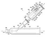
- FIG. 1illustrates a balloon dilation catheter according to the disclosure
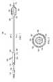
- FIG. 2is cross-sectional view of the shaft of the catheter of FIG. 1 , taken along line 2 - 2 of FIG. 1 ;
- FIG. 3is a length-wise section view of the hub of the balloon dilation catheter of FIG. 1 ;
- FIG. 4is an enlarged view of a portion of the sectional view of FIG. 3 further illustrating the pressure relief port;
- FIG. 5is an end view of the pressure relief port of FIG. 4 ;
- FIG. 6is a length-wise section view of an alternate hub for use with a balloon dilation catheter
- FIG. 7Ais a partial top view of a pressure relief apparatus for an inflation/deflation lumen including a splash guard for preventing an uncontrolled release of pressurized fluid through a pressure relief port;
- FIG. 7Bis a partial lengthwise cross sectional view of the pressure relief apparatus of FIG. 7A ;
- FIGS. 7C , 7 D and 7 Eare enlarged partial cross sectional views of the pressure relief apparatus of FIG. 7A illustrating alternative embodiments of a splash guard;
- FIG. 8Ais a partial cross sectional side view of pressure relief apparatus for a Y-connector hub
- FIG. 8Bis a partial cross sectional top view of the Y-connector hub of FIG. 8A ;
- FIGS. 8C , 8 D and 8 Eare enlarged partial cross sectional views of the Y-connector hub of FIG. 8A illustrating alternative embodiments of a splash guard;
- FIG. 9is a partial cross sectional side view of a Y-connector hub including an extension with a pressure relief port and splash guard;
- FIG. 10Ais a partial top view illustrating an alternate embodiment of a splash guard
- FIG. 10Bis a partial side sectional view of the splash guard of FIG. 10A ;
- FIG. 11Ais a partial top view of an embodiment of a second alternative splash guard.
- FIG. 11Bis a partial side sectional view of the splash guard of FIG. 11A .
- a balloon dilation catheter 100includes a shaft 102 having a proximate end 104 and a distal end 106 .
- a plurality of tubular members disposed in catheter 100define internal, longitudinally extending passages known as lumens.
- An access fitting or hub 110is affixed to the proximal end of catheter shaft 102 to provide access to the lumens.
- One tubular member, the guidewire tubular member 120extends longitudinally through the catheter from hub 110 to the distal end 124 of dilation balloon 108 .
- the guidewire tubular member 120has a bore defining a guidewire lumen through which a conventional guidewire 116 may be directed through the interior of catheter 100 .
- hub 110includes a first port 112 for receiving guidewire 116 therethrough and directing the guidewire into the guidewire lumen in shaft 102 .
- Hub 110further includes a second inflation/deflation port 114 adapted to receive an incompressible inflation medium and direct the medium into an inflation/deflation lumen that extends through the hub and shaft 102 .
- hub 110includes a pressure relief port 134 that extends through the wall of the hub and into the inflation/deflation lumen of the hub.
- a manipulator 118may be provided for rotating and positioning guidewire 116 from the proximal end of catheter 100 .
- balloon 108may be of conventional construction and is typically formed of relatively non-distensible plastic or polymer material such as nylon.
- Non-compliant balloonswill typically expand less than about 10%, and more typically less than about 5%, when pressurized from the rated operating pressure to the balloon's rated burst pressure.
- balloon 108may be plain or reinforced with filaments or fibers.
- balloon 108is shown in an inflated configuration in FIG. 1 with portions of the balloon cut away to better to illustrate the interior structure of catheter 100 .
- balloon 108is illustrated in an inflated configuration, it will be appreciated that when deflated the balloon can typically be folded in such a manner as to have an outside diameter or cross section approximately equal to that of catheter shaft 102 .
- the proximate end 122 of balloon 108may be attached to the distal end 106 of shaft 102 of shaft 102 using various techniques known in the art, for example with an appropriate adhesive such as medical grade epoxy adhesive.
- the distal end 124 of balloon 108is connected with a fluid-tight seal to the outside (i.e. radial) surface of guidewire tubular member 120 , which, as illustrated, extends beyond the distal end 106 of the catheter shaft 102 , passing through the interior of balloon 108 .
- the distal end 124 of balloon 108may be welded to guidewire tubular member 120 or adhered to the guidewire tubular member with an appropriate adhesive to form a fluid-tight seal.
- FIG. 2is a cross-sectional view of catheter shaft 102 taken along line 2 - 2 of FIG. 1 .
- catheter shaft 102may have a coaxial configuration wherein guidewire tubular member 120 defines a guidewire lumen 126 .
- An outer tubular member 132extends coaxially with guidewire lumen 126 and defines an annular inflation/deflation lumen 128 between the inside surface of the outer tubular member and the outside surface of guidewire tubular member 120 .
- Inflation/deflation lumen 128extends from inflation/deflation port 114 of hub 110 to balloon 108 , providing a fluid passageway for the incompressible fluid used to inflate the balloon.
- Catheter shaft 102may include a coating 130 to increase the lubricity of the catheter shaft.
- Outer tubular member 132 and guidewire tubular member 120may be formed from a variety of suitable plastic materials such as nylon-11, nylon-12 and/or a polyether block amide (PEBA).
- PEBApolyether block amide
- guidewire tubular member 120 and/or outer tubular member 132may be formed from PEBA elastomers sold under the trademark Pebax®.
- PEBA elastomersare available in plasticizer and additive-free medical grades having a nominal hardness (Shore D) from about Shore D 30 to about Shore D 72.
- the thermoplastic materials used to make guidewire tubular member 120 and outer tubular member 132may be loaded with materials such as carbon nanotubes or similar materials in order to enhance the strength of the tubular members.
- guidewire tubular member 120 and/or outer tubular member 132may be loaded with up to approximately twenty percent by weight of a radiopaque material such as bismuth.
- FIG. 3is a length wise sectional view of a hub 200 according to the disclosure.
- Hub 200may be molded from an appropriate plastic such as nylon and includes a substantially rigid cylindrical wall 202 having a proximate end 204 and a distal end 206 .
- hub 200may include a separately molded end cap 211 that is glued into the distal end of the hub with an appropriate adhesive to facilitate assembly of the hub.
- Cylindrical wall 202defines a central passage 205 extending longitudinally through hub 200 .
- An outer tubular member 208 of a catheter shaftmay be inserted into the distal end passage 205 and secured to an inside surface of cylindrical wall 202 with an adhesive such as a medical grade epoxy to provide a fluid tight seal.
- a guidewire tubular member 210is positioned inside outer tubular member 208 .
- Guidewire tubular member 210extends past the proximate end of the outer tubular member 208 and may be secured to the inside surface of cylindrical wall 202 with an appropriate adhesive to form a fluid tight seal.
- Guidewire tubular member 208 and the inside surface of cylindrical wall 202 proximate to the end of guidewire tubular memberdefine a guidewire lumen 212 extending through hub 200 .
- an enlarged portion 216 of the proximate end of passage 205serves as a guide for inserting or threading guidewire 232 into hub 200 .
- the inside surface of wall 202 and the outside surface of guidewire tubular member 210define an annular inflation/deflation lumen 214 within hub 200 that extends distally from the location where guidewire tubular member 210 is sealed against the inside surface of wall 202 .
- Inflation/deflation lumen 214extends from hub 200 between the inside surface of the outer tubular member 208 and the outside surface of guidewire tubular member 210 to a dilation balloon such as balloon 108 of FIG. 1 .
- Hub 200includes an inflation/deflation port 218 through which an incompressible fluid (e.g. inflation medium) may be directed into and out of the hub.
- inflation/deflation port 218comprises a cylindrical wall 207 that may be integrally molded with wall 202 .
- wall 207defines a passageway 211 that opens into inflation/deflation lumen 214 at a location distal to the fluid tight seal between guidewire tubular member 210 and the inside surface of cylindrical wall 202 .
- cylindrical wall 207includes an enlarged end 209 to facilitate connection of a source of pressurized fluid to hub 200 .
- a pressure relief port 220is formed through cylindrical wall 202 .
- Pressure relief port 220opens into inflation/deflation lumen 214 and a pressure relief member 222 is secured across the pressure relief port to form a fluid tight seal.
- pressure relief member 222may be one or more layers of a suitable plastic film having a tensile strength such that film ruptures or tears when the pressure in inflation/deflation lumen 214 exceeds a predetermined value, for example a selected pressure between 6 and 30 atmospheres.
- the predetermined pressure valuemay be approximately equal to the rated burst pressure of a dilation balloon used with a catheter incorporating hub 200 . In other variations, the predetermined value may be greater than or less than the rated burst pressure of the balloon.
- FIG. 4is an enlarged view of the encircled portion of FIG. 3 further illustrating relief port 220 .
- relief port 220includes an enlarged outwardly opening passage 226 and a smaller diameter inner passage 228 that opens into inflation/deflation lumen 214 .
- An annular wall 230extends radially between outwardly opening passage 226 and inner passage 228 .
- pressure relief member 222extends across inner passage 228 and annular wall 230 .
- Pressure relief member 222may be glued to annular wall 230 with an appropriate adhesive, such as a medical grade epoxy, to form a fluid-tight seal across relief port 220 .
- pressure relief member 222may be solvent welded or thermally or ultrasonically welded in place.
- a cylindrical retainer 224is positioned in outwardly opening passage 226 over pressure relief member 222 .
- pressure relief member 222is positioned between retainer 224 and annular wall 228 .
- FIG. 5is an enlarged end view of relief port 220 .
- retainer 224has an outside diameter approximately equal to the inside diameter of outwardly opening passage 226 and a centrally located cylindrical opening 234 having a diameter approximately equal to the diameter of inner passage 228 through which pressure relief member 222 is exposed.
- Retainer 224may be secured in outwardly opening passage 226 and/or to pressure relief member 222 with an appropriate adhesive or by means of solvent, thermal or ultrasonic welding.
- relief port 220has a generally circular configuration. However, in other embodiments relief port 220 may be rectangular, oval or polygonal. In other variations relief member 222 and retainer 224 may be formed as a single integral component by means of, for example, molding. In yet other embodiments, pressure relief member 222 may be scored or otherwise weakened in order to burst at a selected predetermined pressure. Although as illustrated, pressure relief member 222 is formed from one or more layers of a plastic film, it is contemplated that the relief member may be formed form other materials having the same or different geometries. For example, pressure relief member may be formed as a thin metal disk having a flat or curved cross-section.
- a catheter hub 300comprises a substantially rigid, integrally formed body 302 having a proximate end 304 and a distal end 306 .
- Body 302may be molded from a suitable plastic such as nylon.
- a guidewire tubular member 310passes through a longitudinally extending central passage 312 formed in body 302 .
- a proximate portion of guidewire tubular member 310is encased in a first outer tubular member 308 that extends into the proximate end of central passage 312 .
- First outer tubular member 308 and guidewire tubular member 310are secured in position in hub 300 with an adhesive 326 that forms a fluid tight seal between the guidewire tubular member and the inside surface of central passage 312 .
- a second outer tubular member 314is positioned over guidewire tubular member 310 and secured in central passage 312 at the distal end 306 of hub 300 with an appropriate adhesive or by means of thermal, solvent or ultrasonic welding.
- the inner surface of central passage 312 and the outer surface of guidewire tubular member 310define an annular inflation/deflation lumen 328 that extends from hub 300 between the outer surface of guidewire tubular member 310 and the inner surface of second outer tubular member 314 .
- an inflation/deflation tube 316is secured in an inflation/deflation port 318 is formed in body 302 for providing pressured fluid through hub 300 to a dilation balloon.
- Inflation/deflation tube 316may be secured in inflation/deflation port 318 by means of an adhesive or by thermal, ultrasonic or solvent welding.
- inflation/deflation port 318is formed at an acute angle to central passage 312 and opens into inflation/deflation lumen 328 distal to the fluid tight seal formed by adhesive 326 between the inside surface of the central passage and guidewire tubular member 310 .
- a pressure relief port 320 formed in body 302extends outwardly from inflation/deflation lumen 328 at a location distal to the fluid tight seal formed by adhesive 326 between the inside surface of the central passage and guidewire tubular member 310 .
- pressure relief port 320is essentially identical to pressure relief port 220 of FIGS. 4 and 5 .
- a pressure relief member 322is secured across pressure relief port 320 to form a fluid tight seal.
- a cylindrical retainer 324is used to secure pressure relief member 322 across pressure relief port 320 .
- Pressure relief member 322is formed from a material, such as a plastic film, such that the member will rupture or tear when the pressure in inflation/deflation lumen 328 reaches or exceeds a predetermined level.
- the predetermined pressureis equal to or greater than the rated burst pressure of the dilation balloon connected to hub 300 .
- balloon 108may remain in an inflated or partially inflated condition in a patient's blood vessel.
- the blood vesselmay remain occluded for longer than desired if the balloon cannot be deflated with the use of negative pressure. This may be particularly problematic in the case of a substantially inelastic non-compliant or semi-compliant balloon since the balloon may not collapse or only partially collapse without the use of negative pressure to aspirate the incompressible fluid from the balloon.
- pressure relief ports 220 and 320are located in hubs 200 and 300 at locations where the ports may be rapidly sealed in the event of a rupture of pressure relief members 222 or 322 .
- a practitionermay place a finger or thumb over the pressure relief port to seal the port and then apply a negative pressure to balloon through the catheter to aspirate the fluid from the balloon.
- a piece of tape or similar materialmay be placed over pressure relief ports 220 or 320 to seal the port while the balloon is deflated.
- pressure relief ports 220 and 320along with relief members 222 and 322 provide a means of preventing over-inflation of dilation balloons during procedures such as angioplasty, the ports may also be rapidly re-sealed to allow for rapid controlled deflation of a dilation balloon in the case of a rupture of the relief member.
- the ports and apparatus described aboveare formed in a wall of a catheter hub, it is contemplated that the ports could be positioned in a wall of the catheter shaft or in an inflation/deflation port connected to the hub. Further, while the pressure relief ports are described in connection with catheters having coaxially configured catheter shafts, the ports may be adapted for use with other types of catheters. Such catheters may have non-coaxial multi-lumen shafts such as extruded dual lumen shafts. Additionally, while the pressure relief apparatus had been described in connection with non-compliant dilation balloons, the apparatus may be used with semi-compliant and complaint balloons.
- rupture of relief member 222 ( FIG. 4 ) or 322 ( FIG. 6 ) in some casesmay result in pressurized fluid contained in inflation/deflation lumen 214 ( FIG. 3 ) or 328 ( FIG. 6 ) and balloon 108 being ejected though pressure relief ports 220 and 320 .
- FIG. 7Ais a partial top view of a pressure relief apparatus including a splash guard 434 for preventing an uncontrolled release of pressurized fluid through a pressure relief port 422 formed in a hub 400 of the apparatus.
- Hub 400includes a body 402 having a proximal end 404 , a distal end 406 and a fitting or connector 408 at proximal end 404 for connecting the hub to a source of pressurized fluid.
- Hub 400may be molded from an appropriate plastic such as nylon.
- the connector 408is a locking female tapered cone luer fitting, for example, a female Luer lock-type fitting such as those sold by Becton Dickinson under the trademark Luer-Lok®.
- connector 408may be a female slip tip-type fitting such as those sold by Becton Dickinson under the trademark Luer-Slip® or another female 6% tapered cone luer connector fitting such as those described in the ISO 594 standard.
- the connector 408may be a male tapered cone luer fitting, for example, a male Luer lock-type fitting such as a Luer-Lok® fitting, a male slip tip-type fitting such as a Luer-Slip® fitting or another male 6% tapered cone luer connector fitting such as those described in the ISO 594 standard.
- the connector 408may be a male or female permanent connector fitting, e.g., a glue-in connector fitting.
- FIG. 7Bis a partial lengthwise cross sectional view of the pressure relief apparatus of FIG. 7A .
- a generally cylindrical wall 410defines an inflation/deflation lumen 412 that extends through hub 400 from proximal end 404 to distal end 406 along a longitudinal axis A-A′ of the hub.
- inflation/deflation lumen 412includes a large diameter proximal portion 414 , a small diameter portion 416 and a tapered portion 418 extending between large diameter proximal portion 414 and small diameter portion 416 .
- a large diameter distal portion 420 of inflation/deflation lumen 412is configured to receive a pressed or glued in hub extension or catheter shaft (not shown).
- large diameter proximal portion 414is outwardly tapered toward proximal end 404 from tapered portion 418 and configured to receive a corresponding Luer-type fitting.
- Distal end 406may be configured to receive the distal end of a catheter shaft (not shown) connected to hub 400 by means of thermal, solvent or ultrasonic welding, a glue-in connection, a Luer-type fitting or other connection means.
- Hub 400is configured with a pressure relief port 422 that extends through wall 410 and opens into tapered portion 418 of inflation/deflation lumen 412 .
- pressure relief port 422is perpendicular to longitudinal axis A-A′.
- FIGS. 7C , 7 D and 7 Eare enlarged cross sectional views of pressure relief port 422 with splash guards 434 a , 434 b and 434 c , respectively.
- FIG. 7Cis an enlarged cross sectional view of a portion of hub 400 further illustrating a splash guard 434 a .
- relief port 422includes a generally cylindrical relatively larger diameter, outwardly opening passage 424 and a generally cylindrical relatively smaller, diameter inner passage 426 that opens into the tapered portion inflation/deflation lumen 412 .
- An annular wall 428extends radially between outwardly opening passage 424 and inner passage 426 .
- a pressure relief member 430extends across inner passage 426 and annular wall 428 .
- a cylindrical retaining ring 432is positioned in outwardly opening passage 424 over pressure relief member 430 .
- Pressure relief member 430may be glued to annular wall 428 with an appropriate adhesive, such as a medical grade epoxy, to form a fluid-tight seal across relief port 422 .
- pressure relief member 430may be solvent welded or thermally or ultrasonically welded in place.
- Pressure relief member 430is selected to fail at a predetermined pressure to release pressure from the inflation/deflation lumen 412 through pressure relief port 422 when the pressure in the inflation/deflation lumen exceeds the predetermined pressure.
- Pressure relief member 422may be formed from one or more layers of a suitable plastic film having a tensile strength such that film ruptures or tears when the pressure in inflation/deflation lumen 412 exceeds a predetermined value, for example a selected pressure between 6 and 30 atmospheres.
- the predetermined pressure valuemay be approximately equal to the rated burst pressure of a dilation balloon used with a catheter incorporating hub 400 . In other variations, the predetermined value may be greater than or less than the rated burst pressure of the balloon.
- splash guard 434 acomprises a cylindrical body generally corresponding to geometry of outwardly opening passage 424 .
- Splash guard 434 ahas an outwardly facing exterior surface 436 , an inwardly facing interior surface 438 and a cylindrical side wall 440 .
- Splash guard 434 amay be formed from a fluid permeable wire or plastic mesh material or a sheet material perforated, coiled or folded to create a plurality of relatively narrow, (i.e., compared to the dimensions of passages 424 , 426 ) fluid passages extending between inwardly facing interior surface 438 and outwardly facing exterior surface 436 .
- the fluid passagesmay be relatively straight from interior surface 438 to exterior surface 436 , whereas in other materials the fluid passages may be curved, meandering or interconnected with one another, i.e., forming a network of interconnected passages between the interior and exterior surfaces.
- outwardly facing exterior surface 436is flush with the exterior surface of body 402 of hub 400 with inwardly facing interior surface 438 positioned against or adjacent to pressure relief member 430 .
- outwardly facing exterior surface 436 of splash guard 434 amay be recessed relative to the exterior surface of body 402 of hub 400 and inwardly facing interior surface 438 may be positioned outwardly from pressure relief member 430 .
- Pressurized fluid released upon a failure or rupture of pressure relief member 430flows through generally cylindrical smaller, diameter inner passage 426 and impinges upon splash guard 434 a upon entering generally cylindrical enlarged, outwardly opening passage 424 of pressure relief port 422 .
- the pressurized fluidmust flow through the plurality of relatively narrow passages to pass through splash guard 434 a .
- splash guard 434 apermits the flow of pressurized fluid through pressure relief port 422
- the narrow passages of the splash guarddissipate a significant fraction of the fluid's pressure by the time the fluid reaches outer surface 436 of the splash guard, thereby preventing the pressurized fluid from taking an unobstructed direct linear path through generally cylindrical enlarged, outwardly opening passage 424 and spurting in an uncontrolled fashion from pressure relief port 422 to the external environment.
- FIG. 7Dis an enlarged cross sectional view of a portion of hub 400 illustrating a splash guard 434 b having an exterior portion 442 extending outwardly from the exterior surface the exterior surface of body 402 of hub 400 .
- Exterior portion 442 of splash guard 434 bmay be have a circular, rectangular or other geometry and may be formed integrally with an interior portion 444 of the splash guard. As illustrated an interior face or surface 446 is positioned against or adjacent to pressure relief member 430 ; however, the interior surface may alternatively be positioned outwardly from pressure relief member 430 .
- Splash guard 434 bis similar to splash guard 434 a and may be a cylindrical body formed from a fluid permeable wire or plastic mesh material or a sheet material perforated, coiled or folded to create a plurality of relatively narrow fluid passages extending between inwardly facing interior surface 438 and outwardly facing exterior surface 436 of pressure relief port 422 .
- Splash guard 434 bfunctions in the same manner as splash guard 434 a to dissipate pressure and thereby prevent an uncontrolled release of pressurized fluid through pressure relief port 422 with exterior portion 442 of splash guard 434 b providing additional protection by extending the path that fluid must follow to flow from pressure relief port 422 and increasing the pressure drop across the splash guard.
- Exterior portion 442also provides a tactile means of locating pressure relief port 422 in the event of a rupture of pressure relief member 430 .
- a practitionermay place a finger or thumb over exterior portion 442 to seal pressure relief port 422 and then apply a negative pressure to an attached balloon 108 ( FIG. 1 ) through a catheter (not shown) attached to hub 400 to withdraw fluid from the balloon
- FIG. 7Eis an enlarged cross sectional view of a portion of hub 400 illustrating a splash guard 434 c illustrated in phantom.
- Splash guard 434 cis formed from a band of a fluid permeable material such as a cloth, mesh, foam or perforated sheet material. It will be understood that a fluid permeable material includes a plurality of relatively narrow fluid passages passing through the material.
- Splash guard 434 cextends circumferentially around the perimeter of hub 400 and may be fastened to the hub with an appropriate adhesive or by means of solvent, thermal or ultrasonic welding. As illustrated, splash guard 434 c extends around the entire periphery of hub 400 . In different embodiments splash guard 434 may extend only partially around hub 400 .
- Splash guard 434 cthereby prevents the pressurized fluid from taking an unobstructed direct linear path when exiting pressure relief port 422 and spurting in an uncontrolled fashion from the pressure relief port to the external environment.
- FIG. 8Ais a partial cross sectional side view of a Y-connector hub 500 .
- FIG. 8Bis a partial cross sectional top view of Y-connector hub 500 .
- Hub 500includes a body 502 having a proximal end 504 and distal end 506 with a central lumen 508 extending longitudinally through body 502 along a central longitudinal axis B-B′.
- Central lumen 508includes a proximal portion 510 , a larger diameter distal portion 512 and a tapered portion 514 that extends between proximal portion 510 and distal portion 512 .
- Large diameter distal portion 512may be configured to receive a catheter shaft (not shown) therein with a glued or welded connection.
- a branch lumen 516extends at an angle along a second axis C-C′ of body 502 intersecting and opening into central lumen 508 midway along the length of body 502 of hub 500 .
- Branch lumen 516includes a first, proximal portion 518 , a distal portion 520 and a tapered portion 522 extending between the proximal and distal portions of branch lumen 516 .
- a tube 524is received in proximal portion 518 of branch lumen 516 .
- Tube 524may be connected to hub 500 by means of an appropriate adhesive or by means of solvent, thermal or sonic welding.
- central lumen 508 and branch lumen 516may be provided with connectors, such as Luer-type connectors at the ends thereof to facilitate connection of a catheter shaft and/or pressurization tube to hub 500 .
- connectorssuch as Luer-type connectors at the ends thereof to facilitate connection of a catheter shaft and/or pressurization tube to hub 500 .
- Luer-type connectorssuch as those sold by Becton Dickinson under the trademark Luer-Lok
- female slip tip-type fittingsuch as those sold by Becton Dickinson under the trademark Luer-Slip® or another female 6% tapered cone luer connector fitting such as those described in the ISO 594 standard may be utilized.
- a male tapered cone luer fittingfor example, a male Luer lock-type fitting such as a Luer-Lok® fitting, a male slip tip-type fitting such as a Luer-Slip® fitting or another male 6% tapered cone luer connector fitting such as those described in the ISO 594 standard may be utilized.
- Tube 524may be connected to a source of pressurized fluid to inflate a balloon, such as balloon 108 of FIG. 1 attached to hub 500 by means of a catheter shaft (not shown).
- Central lumen 508 , branch lumen 516 and tube 524thereby form an inflation/deflation lumen 530 that extends though body 502 of hub 500 .
- a pressure relief port 532is formed in body 502 , extending from distal portion 518 of branch lumen 516 and opening to the exterior of body 502 . As illustrated pressure relief port 532 extends perpendicular to axis C-C′ of branch lumen 516 . Pressure relief port 532 includes a generally cylindrical enlarged, outwardly opening passage 534 and a generally cylindrical smaller, diameter inner passage 536 that opens into distal portion 518 of branch lumen 516 . An annular wall 538 extends radially between outwardly opening passage 534 and inner passage 536 .
- a pressure relief member 540extends across inner passage 536 and annular wall 538 .
- Pressure relief member 540may be formed from one or more layers or suitable plastic film having a tensile strength such that film ruptures when the pressure in branch lumen 516 exceeds a predetermined value.
- Pressure relief member 540may be may be glued to annular wall 538 with an appropriate adhesive, such as a medical grade epoxy or thermally, ultrasonically or solvent welded in place to form a fluid tight seal across pressure relief port 532 .
- a cylindrical retaining ring 542may be may be welded or glued in place in outwardly opening passage 534 over pressure relief member 540 to aid in retaining the pressure relief member in position.
- a splash guard 542is positioned across pressure relief port 532 for preventing a linear uncontrolled release of pressurized fluid through the pressure relief port.
- FIGS. 8C , 8 D and 8 Eare enlarged cross sectional views of pressure relief port 532 with splash guards 544 a , 544 b and 544 c , respectively.
- Splash guards 544 a - 544 care substantially identical to, and function in the same manner as splash guards 434 a - 434 c of FIGS. 7C-7E .
- FIG. 9is a partial cross sectional side view of a Y-connector hub 600 with removable extension 630 .
- Hub 600has a substantially cylindrical wall 602 with a proximal end 604 and a distal end 606 .
- Cylindrical wall 602defines central lumen 608 extending along a central axis D-D′ between the proximal end 604 and distal end 606 .
- Central lumen 608has a large diameter proximal portion 610 with an outwardly taped end section 612 that may be configured to receive a male Leur-type fitting or an end of a tubular member (not shown) secured in tapered section 612 with an appropriate adhesive or by means of solvent, thermal or ultrasonic welding.
- Central lumen 608includes a narrow diameter distal portion 609 extending from a distal end of large diameter portion 610 to distal end 606 of cylindrical wall 602 with a enlarged end portion 614 .
- End portion 614may be configured to receive the proximal end of a tubular member such as a catheter shaft with a glued or welded connection and/or provided with a connector such as a Leur-type fitting.
- Y-connector hub 600includes a branch lumen 620 extending from a proximal end 622 through hub 600 and opening into large diameter proximal portion 610 of central lumen 608 midway along the length of the hub.
- An angled cylindrical wall 624defines a portion of branch lumen 620 that extends from cylindrical wall 602 along an axis E-E′ that intersects axis D-D′ at an acute angle.
- proximal end 622 of angled cylindrical wall 624includes a externally threaded female Leur-type connection 628 with an outwardly tapered portion 626 of branch lumen 620 for receiving a corresponding male Leur-type fitting 632 at the distal end of a removable extension 630 of branch lumen 620 .
- Leur-type fitting 632 of extension 630includes a male insert 634 and a collar 636 with internal threads 638 for securing fitting 632 to connector 628 .
- a passage 644extends though extension 630 from distal end 638 to proximal end 640 of the extension with a female Leur-type connection 642 at the proximal end of the extension.
- Passage 640includes a narrow diameter distal portion 646 that opens into a tapered, larger diameter proximal end portion 648 which is configured to receive a male luer-type fitting.
- central lumen 610 , branch lumen 620 and passage 644are in fluid communication and provide a fluid path through extension 630 and hub 600 .
- larger diameter proximal end portion 648may be configured to receive an end of a tubular member secured therein with an appropriate adhesive or by welding.
- Extension 630is configured for attachment to a source of pressurized fluid for inflating a balloon such as balloon 108 of FIG. 1 connected to a catheter shaft (not shown) connected in turn to distal end 606 of hub 600 .
- Central lumen 608 , branch lumen 620 and passage 640thereby form an inflation/deflation lumen for inflating and deflating a balloon connected to a catheter shaft (not shown) connected in turn to distal end 606 of hub 600 for passage of pressurized fluid therethrough.
- hub 600 and extension 630may be provided with female Luer lock-type fitting such as those sold by Becton Dickinson under the trademark Luer-Lok, female slip tip-type fitting such as those sold by Becton Dickinson under the trademark Luer-Slip® or another female 6% tapered cone luer connector fitting such as those described in the ISO 594 standard.
- Hub 600 and extension 630may also be provided a male tapered cone luer fittings, such as a male Luer lock-type fitting such as a Luer-Lok® fitting, a male slip tip-type fitting such as a Luer-Slip® fitting or another male 6% tapered cone luer connector fitting such as those described in the ISO 594.
- extension 630defines a fluid inlet port 670 configured with a female tapered cone luer fitting and a fluid outlet port 672 configured with a male tapered cone luer fitting.
- a pressure relief port 650is formed in a cylindrical sidewall 652 of extension 630 , extending though the sidewall to narrow diameter distal portion 646 of passage 644 .
- Pressure relief port 650is positioned perpendicular to axis E-E′ and includes a generally cylindrical enlarged, outwardly opening passage 654 and a generally cylindrical smaller, diameter inner passage 656 that opens into the narrow diameter distal portion 646 of passage 644 .
- An annular wall 658extends radially between outwardly opening passage 654 and inner passage 656 .
- a pressure relief member 660extends across inner passage 656 and annular wall 658 .
- Pressure relief member 660may be formed from one or more layers of a film or sheet material selected to rupture or fail at a predetermined pressure.
- the predetermined pressure valuemay be greater than, less than or approximately equal to the rated burst pressure of a dilation balloon used with a catheter apparatus incorporating 600 .
- Pressure relief member 660may be glued with an appropriate adhesive, such as a medical grade epoxy, to annular wall 658 to form a fluid-tight seal across relief port 650 .
- pressure relief member 660may be solvent, thermally or ultrasonically welded to annular wall 658 .
- a cylindrical retaining ring 662may be positioned in outwardly opening passage 654 over pressure relief member 660 , retaining the pressure relief member between annular wall 658 and the retaining ring. Retaining ring 662 may be glued or welded in place in enlarged, outwardly opening passage 654 of pressure relief port 650 .
- a splash guard 664is positioned in pressure relief port 650 .
- Splash guard 664comprises a cylindrical body generally corresponding to the geometry of generally cylindrical enlarged, outwardly opening passage 654 of the pressure relief port.
- Splash guard 664may be formed from a fluid permeable wire or plastic mesh material or a sheet material perforated, coiled or folded to create a plurality of relatively narrow fluid passages extending between inwardly facing interior surface 666 and outwardly facing exterior surface 668 of the splash guard.
- outwardly facing exterior surface 668is flush with the exterior surface extension 630 with inwardly facing interior surface 666 positioned against or adjacent to pressure relief member 660 .
- outwardly facing exterior surface 668 of splash guard 664may be recessed or elevated relative to the exterior surface of extension 630 and inwardly facing interior surface 666 may be positioned outwardly from pressure relief member 660 .
- extension 630includes a pressure relief port 650 without splash guard 664 .
- Splash guard 664obstructs the flow of fluid though pressure relief port 650 and increases the pressure drop across the relief port thereby preventing fluid flowing through the port from taking an unobstructed linear path through the port and spurting into the external environment.
- splash guard 664may be substantially identical to, and function in the same manner as splash guards 434 a - 434 c of FIGS. 7C-7E .
- FIG. 10Ais a partial top view of an alternate embodiment of a splash guard 700 .
- FIG. 10Bis a partial side sectional view of the splash guard of FIG. 10A positioned in a pressure relief port 708 substantially identical to pressure relief ports 422 , 532 and 660 of FIGS. 7-9 .
- Splash guard 700is formed from one or more layers of a perforated sheet material 702 such as a plastic or metal sheet.
- Splash guard 700may include a rim or ring 706 extending around the periphery of sheet 702 configured to rest on or be attached to the exterior surface of a tube 714 such as extension 630 ( FIG. 9 ) or hub, such as hub 400 ( FIG. 7 ) that defines an inflation/deflation lumen.
- perforated sheet 702may be formed integrally with pressure relief port 708 and tube 714 by means of molding or machining.
- Pressure relief port 708Pressurized fluid flowing through pressure relief port 708 must pass through perforations 704 which form multiple, relatively narrow, fluid flow channels through splash guard 700 which increases the pressure drop across the splash guard, slowing the rate of fluid flow. Splash guard 700 thereby prevents unobstructed flow though pressure relief port 708 which could result in an uncontrolled spray, stream or spurt of fluid from the port in the event of a failure or rupture of pressure relief member 712 .
- FIG. 11Ais a partial top view of an embodiment of a second alternative splash guard 800 .
- FIG. 11Bis a partial side sectional view of the splash guard of FIG. 11A positioned in a pressure relief port 808 substantially identical to pressure relief ports 422 , 532 and 660 of FIGS. 7-9 including a pressure relief member 810 .
- Splash guard 800may include a rim or ring 804 extending around the periphery of a cylindrical sidewall 814 of the splash guard. Ring 804 is configured to rest on or be attached to the exterior surface of a tube 816 such as extension 630 ( FIG. 9 ) or hub, such as hub 400 ( FIG. 7 ) that defines an inflation/deflation lumen.
- Splash guard 800includes one or more baffles 802 positioned in pressure relief port 808 that partially obstruct the pressure relief port to form a labyrinth of relatively narrow flow passages. As illustrated, baffles 802 extend perpendicular from a cylindrical sidewall 814 of splash guard 800 such that fluid passing through pressure relief port 808 must flow around baffles 802 which diverts the flow of the fluid though pressure relief port 808 and increases the pressure drop across the pressure relief port.
- Splash guard 800may be formed from a suitable plastic material such as nylon.
- baffles 802may be formed integrally with pressure relief port 808 and tube 816 by means of molding or machining in which case, the baffles would be positioned perpendicular to sidewall 806 of pressure relief port 808 .
- Baffles 802 of splash guard 800change the direction of flow of a fluid flowing though pressure relief port 808 at least twice, thereby slowing the flow and preventing direct linear flow though the pressure relief port that may result in an uncontrolled spray, stream or spurt of fluid from the port in the event of a failure or rupture of pressure relief member 810 .
- this balloon catheter pressure relief valveprovides a means of preventing over-pressurization of a dilation catheter balloon.
- the drawings and detailed description hereinare to be regarded in an illustrative rather than a restrictive manner, and are not intended to be limiting to the particular forms and examples disclosed.
- includedare any further modifications, changes, rearrangements, substitutions, alternatives, design choices, and embodiments apparent to those of ordinary skill in the art, without departing from the spirit and scope hereof, as defined by the following claims.
- the following claimsbe interpreted to embrace all such further modifications, changes, rearrangements, substitutions, alternatives, design choices, and embodiments.
Landscapes
- Health & Medical Sciences (AREA)
- Life Sciences & Earth Sciences (AREA)
- Heart & Thoracic Surgery (AREA)
- Public Health (AREA)
- Engineering & Computer Science (AREA)
- Anesthesiology (AREA)
- Biomedical Technology (AREA)
- Hematology (AREA)
- Animal Behavior & Ethology (AREA)
- General Health & Medical Sciences (AREA)
- Veterinary Medicine (AREA)
- Biophysics (AREA)
- Pulmonology (AREA)
- Child & Adolescent Psychology (AREA)
- Vascular Medicine (AREA)
- Media Introduction/Drainage Providing Device (AREA)
Abstract
Description
Claims (19)
Priority Applications (1)
| Application Number | Priority Date | Filing Date | Title |
|---|---|---|---|
| US14/616,328US9259559B2 (en) | 2009-02-23 | 2015-02-06 | Balloon catheter pressure relief valve |
Applications Claiming Priority (3)
| Application Number | Priority Date | Filing Date | Title |
|---|---|---|---|
| US12/390,573US8814899B2 (en) | 2009-02-23 | 2009-02-23 | Balloon catheter pressure relief valve |
| US14/468,882US20140364893A1 (en) | 2009-02-23 | 2014-08-26 | Balloon catheter pressure relief valve |
| US14/616,328US9259559B2 (en) | 2009-02-23 | 2015-02-06 | Balloon catheter pressure relief valve |
Related Parent Applications (1)
| Application Number | Title | Priority Date | Filing Date |
|---|---|---|---|
| US14/468,882Continuation-In-PartUS20140364893A1 (en) | 2009-02-23 | 2014-08-26 | Balloon catheter pressure relief valve |
Publications (2)
| Publication Number | Publication Date |
|---|---|
| US20150231378A1 US20150231378A1 (en) | 2015-08-20 |
| US9259559B2true US9259559B2 (en) | 2016-02-16 |
Family
ID=53797158
Family Applications (1)
| Application Number | Title | Priority Date | Filing Date |
|---|---|---|---|
| US14/616,328Expired - Fee RelatedUS9259559B2 (en) | 2009-02-23 | 2015-02-06 | Balloon catheter pressure relief valve |
Country Status (1)
| Country | Link |
|---|---|
| US (1) | US9259559B2 (en) |
Cited By (2)
| Publication number | Priority date | Publication date | Assignee | Title |
|---|---|---|---|---|
| US9872718B2 (en)* | 2012-04-27 | 2018-01-23 | Medtronic Adrian Luxembourg S.a.r.l. | Shafts with pressure relief in cryotherapeutic catheters and associated devices, systems, and methods |
| EP3771477A1 (en) | 2019-08-01 | 2021-02-03 | Biotronik Ag | Connection design for a tavi handle luer lock |
Families Citing this family (8)
| Publication number | Priority date | Publication date | Assignee | Title |
|---|---|---|---|---|
| US10342699B2 (en) | 2012-08-03 | 2019-07-09 | J.D. Franco & Co., Llc | Systems and methods for treating eye diseases |
| US10080875B2 (en)* | 2015-12-01 | 2018-09-25 | Medtronic Vascular, Inc. | Handle component for providing a pressurized material |
| AU2018213053A1 (en) | 2017-01-25 | 2019-08-29 | J.D. Franco & Co., Llc | Blood vessel access and closure devices and related methods of use |
| US10779929B2 (en) | 2017-10-06 | 2020-09-22 | J.D. Franco & Co., Llc | Treating eye diseases by deploying a stent |
| US10758254B2 (en) | 2017-12-15 | 2020-09-01 | J.D. Franco & Co., Llc | Medical systems, devices, and related methods |
| US11272946B2 (en)* | 2018-03-09 | 2022-03-15 | Acclarent, Inc. | Fluid fitting for dilation instrument |
| US10765843B2 (en) | 2018-12-31 | 2020-09-08 | J.D. Franco & Co., Llc | Intravascular devices, systems, and methods to address eye disorders |
| JP7281596B2 (en)* | 2020-02-14 | 2023-05-25 | オリンパス株式会社 | ultrasound endoscope |
Citations (141)
| Publication number | Priority date | Publication date | Assignee | Title |
|---|---|---|---|---|
| US1596284A (en) | 1926-08-17 | malmgren | ||
| US2043083A (en) | 1932-07-08 | 1936-06-02 | Wappler Frederick Charles | Therapeutic electrode and plug therefor |
| US3769981A (en) | 1972-02-09 | 1973-11-06 | Kendall & Co | Urinary catheter |
| US3981415A (en) | 1975-10-29 | 1976-09-21 | E. I. Du Pont De Nemours And Company | Dispenser with expansible member and contracting fabric |
| US4367396A (en) | 1980-07-21 | 1983-01-04 | Pace Incorporated | Thermal tool including twisted tip for the tool and method of making tip |
| US4482516A (en) | 1982-09-10 | 1984-11-13 | W. L. Gore & Associates, Inc. | Process for producing a high strength porous polytetrafluoroethylene product having a coarse microstructure |
| US4572186A (en) | 1983-12-07 | 1986-02-25 | Cordis Corporation | Vessel dilation |
| US4637396A (en) | 1984-10-26 | 1987-01-20 | Cook, Incorporated | Balloon catheter |
| US4652258A (en) | 1984-12-18 | 1987-03-24 | The Kendall Company | Catheter with expansible connector and method |
| US4702252A (en) | 1983-10-13 | 1987-10-27 | Smiths Industries Public Limited Company | Catheters |
| US4704130A (en) | 1985-10-18 | 1987-11-03 | Mitral Medical, International, Inc. | Biocompatible microporous polymeric materials and methods of making same |
| US4706670A (en) | 1985-11-26 | 1987-11-17 | Meadox Surgimed A/S | Dilatation catheter |
| US4748982A (en) | 1987-01-06 | 1988-06-07 | Advanced Cardiovascular Systems, Inc. | Reinforced balloon dilatation catheter with slitted exchange sleeve and method |
| US4796629A (en) | 1987-06-03 | 1989-01-10 | Joseph Grayzel | Stiffened dilation balloon catheter device |
| US4834755A (en) | 1983-04-04 | 1989-05-30 | Pfizer Hospital Products Group, Inc. | Triaxially-braided fabric prosthesis |
| US4884573A (en) | 1988-03-07 | 1989-12-05 | Leocor, Inc. | Very low profile angioplasty balloon catheter with capacity to use steerable, removable guidewire |
| US4952357A (en) | 1988-08-08 | 1990-08-28 | Scimed Life Systems, Inc. | Method of making a polyimide balloon catheter |
| US4983167A (en) | 1988-11-23 | 1991-01-08 | Harvinder Sahota | Balloon catheters |
| US4998421A (en) | 1990-06-28 | 1991-03-12 | E. I. Du Pont De Nemours And Company | Process for elastic stitchbonded fabric |
| US5042985A (en) | 1989-05-11 | 1991-08-27 | Advanced Cardiovascular Systems, Inc. | Dilatation catheter suitable for peripheral arteries |
| US5046497A (en) | 1986-11-14 | 1991-09-10 | Millar Instruments, Inc. | Structure for coupling a guidewire and a catheter |
| US5061273A (en) | 1989-06-01 | 1991-10-29 | Yock Paul G | Angioplasty apparatus facilitating rapid exchanges |
| US5078727A (en) | 1989-07-14 | 1992-01-07 | Hannam Peter H | Catheters |
| US5108415A (en) | 1988-10-04 | 1992-04-28 | Cordis Corporation | Balloons for medical devices and fabrication thereof |
| US5112304A (en) | 1989-03-17 | 1992-05-12 | Angeion Corporation | Balloon catheter |
| US5116360A (en) | 1990-12-27 | 1992-05-26 | Corvita Corporation | Mesh composite graft |
| US5171297A (en) | 1989-03-17 | 1992-12-15 | Angeion Corporation | Balloon catheter |
| US5201706A (en) | 1989-05-09 | 1993-04-13 | Toray Industries, Inc. | Catheter with a balloon reinforced with composite yarn |
| US5207700A (en) | 1988-08-08 | 1993-05-04 | Scimed Life Systems, Inc. | Polyimide balloon catheter and method of forming a balloon therefor |
| US5264260A (en) | 1991-06-20 | 1993-11-23 | Saab Mark A | Dilatation balloon fabricated from low molecular weight polymers |
| US5270086A (en) | 1989-09-25 | 1993-12-14 | Schneider (Usa) Inc. | Multilayer extrusion of angioplasty balloons |
| US5290306A (en) | 1989-11-29 | 1994-03-01 | Cordis Corporation | Puncture resistant balloon catheter |
| US5295960A (en) | 1992-04-01 | 1994-03-22 | Applied Medical Resources Corporation | Catheter with interior balloon |
| US5304340A (en) | 1991-09-06 | 1994-04-19 | C. R. Bard, Inc. | Method of increasing the tensile strength of a dilatation balloon |
| US5306245A (en) | 1993-02-23 | 1994-04-26 | Advanced Surgical Inc. | Articulating device |
| US5306246A (en) | 1990-11-09 | 1994-04-26 | Boston Scientific Corporation | Balloon for medical catheter |
| US5314443A (en) | 1990-06-25 | 1994-05-24 | Meadox Medicals, Inc. | Prostate balloon dilatation catheter |
| US5344401A (en) | 1991-12-20 | 1994-09-06 | Interventional Technologies Inc. | Catheter balloon formed from a polymeric composite |
| US5358486A (en) | 1987-01-09 | 1994-10-25 | C. R. Bard, Inc. | Multiple layer high strength balloon for dilatation catheter |
| US5410797A (en) | 1992-07-27 | 1995-05-02 | Medtronic, Inc. | Method of making a catheter with flexible side port entry |
| US5451209A (en) | 1992-05-11 | 1995-09-19 | Advanced Cardiovascular Systems, Inc. | Intraluminal catheter with a composite shaft |
| US5451233A (en) | 1986-04-15 | 1995-09-19 | Yock; Paul G. | Angioplasty apparatus facilitating rapid exchanges |
| US5464394A (en) | 1993-06-08 | 1995-11-07 | American Biomed, Inc. | Multilumen percutaneous angioscopy catheter |
| US5470314A (en) | 1994-07-22 | 1995-11-28 | Walinsky; Paul | Perfusion balloon catheter with differential compliance |
| US5478320A (en) | 1989-11-29 | 1995-12-26 | Cordis Corporation | Puncture resistant balloon catheter and method of manufacturing |
| US5477886A (en) | 1991-11-14 | 1995-12-26 | J. Van Beugen Beheer B.V. | Inflatable closing plug for pipes and method of manufacturing same |
| US5492532A (en) | 1989-03-17 | 1996-02-20 | B. Braun Medical, Inc. | Balloon catheter |
| US5549556A (en) | 1992-11-19 | 1996-08-27 | Medtronic, Inc. | Rapid exchange catheter with external wire lumen |
| US5549552A (en) | 1995-03-02 | 1996-08-27 | Scimed Life Systems, Inc. | Balloon dilation catheter with improved pushability, trackability and crossability |
| US5554120A (en) | 1994-07-25 | 1996-09-10 | Advanced Cardiovascular Systems, Inc. | Polymer blends for use in making medical devices including catheters and balloons for dilatation catheters |
| US5575771A (en) | 1995-04-24 | 1996-11-19 | Walinsky; Paul | Balloon catheter with external guidewire |
| US5587125A (en) | 1994-08-15 | 1996-12-24 | Schneider (Usa) Inc. | Non-coextrusion method of making multi-layer angioplasty balloons |
| US5599576A (en) | 1995-02-06 | 1997-02-04 | Surface Solutions Laboratories, Inc. | Medical apparatus with scratch-resistant coating and method of making same |
| US5647848A (en) | 1995-06-07 | 1997-07-15 | Meadox Medicals, Inc. | High strength low compliance composite balloon for balloon catheters |
| US5690642A (en) | 1996-01-18 | 1997-11-25 | Cook Incorporated | Rapid exchange stent delivery balloon catheter |
| US5728063A (en) | 1994-11-23 | 1998-03-17 | Micro International Systems, Inc. | High torque balloon catheter |
| US5741325A (en) | 1993-10-01 | 1998-04-21 | Emory University | Self-expanding intraluminal composite prosthesis |
| US5752934A (en) | 1995-09-18 | 1998-05-19 | W. L. Gore & Associates, Inc. | Balloon catheter device |
| US5759172A (en) | 1995-04-10 | 1998-06-02 | Cordis Corporation | Balloon catheter with lobed balloon and method for manufacturing such a catheter |
| US5769817A (en) | 1997-02-28 | 1998-06-23 | Schneider (Usa) Inc. | Coextruded balloon and method of making same |
| US5772681A (en) | 1993-03-02 | 1998-06-30 | Metra Aps | Dilation catheter |
| US5788979A (en) | 1994-07-22 | 1998-08-04 | Inflow Dynamics Inc. | Biodegradable coating with inhibitory properties for application to biocompatible materials |
| US5797877A (en) | 1993-10-01 | 1998-08-25 | Boston Scientific Corporation | Medical device balloons containing thermoplastic elastomers |
| US5820613A (en) | 1995-01-31 | 1998-10-13 | Cordis Corporation | Balloon catheter with reinforced and elastically deformable basic body |
| US5868779A (en) | 1997-08-15 | 1999-02-09 | Ruiz; Carlos E. | Apparatus and methods for dilating vessels and hollow-body organs |
| US5879369A (en) | 1995-10-11 | 1999-03-09 | Terumo Kabushiki Kaisha | Catheter balloon and balloon catheter |
| US5928181A (en) | 1997-11-21 | 1999-07-27 | Advanced International Technologies, Inc. | Cardiac bypass catheter system and method of use |
| US5972441A (en) | 1993-08-18 | 1999-10-26 | W. L. Gore & Associates, Inc. | Thin-wall polytetrafluoroethylene tube |
| US5980486A (en) | 1989-01-30 | 1999-11-09 | Arterial Vascular Engineering, Inc. | Rapidly exchangeable coronary catheter |
| US6007544A (en) | 1996-06-14 | 1999-12-28 | Beth Israel Deaconess Medical Center | Catheter apparatus having an improved shape-memory alloy cuff and inflatable on-demand balloon for creating a bypass graft in-vivo |
| US6010480A (en) | 1993-08-23 | 2000-01-04 | Boston Scientific Corporation | Balloon catheter |
| US6012457A (en) | 1997-07-08 | 2000-01-11 | The Regents Of The University Of California | Device and method for forming a circumferential conduction block in a pulmonary vein |
| US6015430A (en) | 1987-12-08 | 2000-01-18 | Wall; William H. | Expandable stent having a fabric liner |
| US6024740A (en) | 1997-07-08 | 2000-02-15 | The Regents Of The University Of California | Circumferential ablation device assembly |
| US6024772A (en) | 1996-08-16 | 2000-02-15 | Nec Corporation | Solid electrolyte capacitor and method of manufacturing the same |
| US6027779A (en) | 1993-08-18 | 2000-02-22 | W. L. Gore & Associates, Inc. | Thin-wall polytetrafluoroethylene tube |
| US6036697A (en) | 1998-07-09 | 2000-03-14 | Scimed Life Systems, Inc. | Balloon catheter with balloon inflation at distal end of balloon |
| US6117101A (en) | 1997-07-08 | 2000-09-12 | The Regents Of The University Of California | Circumferential ablation device assembly |
| US6124007A (en) | 1996-03-06 | 2000-09-26 | Scimed Life Systems Inc | Laminate catheter balloons with additive burst strength and methods for preparation of same |
| US6127597A (en) | 1997-03-07 | 2000-10-03 | Discotech N.V. | Systems for percutaneous bone and spinal stabilization, fixation and repair |
| US6156254A (en) | 1996-08-02 | 2000-12-05 | Ranier Limited | Method of manufacturing a balloon member for a balloon catheter |
| US6159238A (en) | 1998-03-04 | 2000-12-12 | Scimed Life Systems, Inc | Stent having variable properties and method of its use |
| US6164283A (en) | 1997-07-08 | 2000-12-26 | The Regents Of The University Of California | Device and method for forming a circumferential conduction block in a pulmonary vein |
| US6171297B1 (en) | 1998-06-30 | 2001-01-09 | Schneider (Usa) Inc | Radiopaque catheter tip |
| US6183492B1 (en) | 1997-08-28 | 2001-02-06 | Charles C. Hart | Perfusion-isolation catheter apparatus and method |
| US6187013B1 (en) | 1994-06-06 | 2001-02-13 | Meadox Medicals, Inc. | Catheter with stent and method for the production of a catheter with stent |
| US6186978B1 (en) | 1996-08-07 | 2001-02-13 | Target Therapeutics, Inc. | Braid reinforced infusion catheter with inflatable membrane |
| US6213995B1 (en) | 1999-08-31 | 2001-04-10 | Phelps Dodge High Performance Conductors Of Sc And Ga, Inc. | Flexible tubing with braided signal transmission elements |
| US6234995B1 (en) | 1998-11-12 | 2001-05-22 | Advanced Interventional Technologies, Inc. | Apparatus and method for selectively isolating a proximal anastomosis site from blood in an aorta |
| US6245064B1 (en) | 1997-07-08 | 2001-06-12 | Atrionix, Inc. | Circumferential ablation device assembly |
| US6263236B1 (en) | 1999-11-29 | 2001-07-17 | Illumenex Corporation | Non-occlusive expandable catheter |
| US6270902B1 (en) | 1997-04-23 | 2001-08-07 | C. R. Bard, Inc. | Method of improving the adherence of certain crosslinked polymer coatings containing PEO or PVP to a substrate |
| US6290485B1 (en) | 1995-03-02 | 2001-09-18 | Lixiao Wang | Mold for forming a balloon catheter having stepped compliance curve |
| US6306154B1 (en) | 1997-06-18 | 2001-10-23 | Bhk Holding | Hemostatic system for body cavities |
| US6309379B1 (en) | 1991-05-23 | 2001-10-30 | Lloyd K. Willard | Sheath for selective delivery of multiple intravascular devices and methods of use thereof |
| US6315751B1 (en) | 1997-08-15 | 2001-11-13 | Cleveland Clinic Foundation | Cardiopulmonary bypass system using vacuum assisted venous drainage |
| US6361529B1 (en) | 1998-09-09 | 2002-03-26 | Schneider (Usa) Inc. | Stiffening member in a rapid exchange dilation catheter |
| US20020058960A1 (en) | 1998-04-08 | 2002-05-16 | Hudson John Overton | Hemostatic system for body cavities |
| US6394995B1 (en) | 1998-05-15 | 2002-05-28 | X Technologies Inc. | Enhanced balloon dilatation system |
| US20020077653A1 (en) | 1998-04-08 | 2002-06-20 | Hudson John Overton | Hemostatic system for body cavities |
| US20020161388A1 (en) | 2001-02-27 | 2002-10-31 | Samuels Sam L. | Elastomeric balloon support fabric |
| US6544219B2 (en) | 2000-12-15 | 2003-04-08 | Advanced Cardiovascular Systems, Inc. | Catheter for placement of therapeutic devices at the ostium of a bifurcation of a body lumen |
| US6626889B1 (en) | 2001-07-25 | 2003-09-30 | Advanced Cardiovascular Systems, Inc. | Thin-walled guiding catheter with improved radiopacity |
| US6663648B1 (en) | 2000-06-15 | 2003-12-16 | Cordis Corporation | Balloon catheter with floating stiffener, and procedure |
| US20040015182A1 (en) | 1992-06-02 | 2004-01-22 | Kieturakis Maciej J. | Apparatus and method for developing an anatomic space for laparoscopic procedures with laparoscopic visualization |
| US20040039332A1 (en) | 2002-08-23 | 2004-02-26 | Medtronic Ave, Inc. | Catheter having a low-friction guidewire lumen and method of manufacture |
| US6702782B2 (en) | 2001-06-26 | 2004-03-09 | Concentric Medical, Inc. | Large lumen balloon catheter |
| US6702750B2 (en) | 1986-04-15 | 2004-03-09 | Cardiovascular Imaging Systems, Inc. | Angioplasty apparatus facilitating rapid exchanges and methods |
| US20040073299A1 (en) | 2000-12-16 | 2004-04-15 | Hudson John Overton | Hemostatic device |
| US20040073163A1 (en) | 2001-07-30 | 2004-04-15 | Scimed Life Systems, Inc. | Chronic total occlusion device with variable stiffness shaft |
| US20040082965A1 (en) | 1996-06-14 | 2004-04-29 | Beckham James P. | Medical balloon |
| US6733487B2 (en) | 1990-08-28 | 2004-05-11 | Scimed Life Systems, Inc. | Balloon catheter with distal guide wire lumen |
| US6743196B2 (en) | 1999-03-01 | 2004-06-01 | Coaxia, Inc. | Partial aortic occlusion devices and methods for cerebral perfusion augmentation |
| US6755845B2 (en) | 1992-06-02 | 2004-06-29 | General Surgical Innovations, Inc. | Apparatus and method for developing an anatomic space for laparoscopic hernia repair and patch for use therewith |
| US6761708B1 (en) | 2000-10-31 | 2004-07-13 | Advanced Cardiovascular Systems, Inc. | Radiopaque marker for a catheter and method of making |
| US20040176740A1 (en) | 2003-03-05 | 2004-09-09 | Scimed Life Systems, Inc. | Multi-braid exterior tube |
| US20050027249A1 (en) | 1991-04-05 | 2005-02-03 | Boston Scientific Corporation, A Delaware Corporation | Adjustably stiffenable convertible catheter assembly |
| US20050033225A1 (en) | 2003-08-08 | 2005-02-10 | Scimed Life Systems, Inc. | Catheter shaft for regulation of inflation and deflation |
| US20050102020A1 (en) | 2000-07-24 | 2005-05-12 | Jeffrey Grayzel | Stiffened balloon catheter for dilatation and stenting |
| US6899713B2 (en) | 2000-06-23 | 2005-05-31 | Vertelink Corporation | Formable orthopedic fixation system |
| US20050121073A1 (en)* | 2003-12-05 | 2005-06-09 | Hose Shop, Ltd. | Burst disk assembly |
| US20050123702A1 (en) | 2003-12-03 | 2005-06-09 | Jim Beckham | Non-compliant medical balloon having a longitudinal fiber layer |
| US6905743B1 (en) | 1999-02-25 | 2005-06-14 | Boston Scientific Scimed, Inc. | Dimensionally stable balloons |
| US6911038B2 (en) | 2001-05-08 | 2005-06-28 | Scimed Life Systems, Inc. | Matched balloon to stent shortening |
| US20050267408A1 (en) | 2004-05-27 | 2005-12-01 | Axel Grandt | Catheter having first and second guidewire tubes and overlapping stiffening members |
| US20050271844A1 (en) | 2004-06-07 | 2005-12-08 | Scimed Life Systems, Inc. | Artificial silk reinforcement of PTCA balloon |
| US6977103B2 (en) | 1999-10-25 | 2005-12-20 | Boston Scientific Scimed, Inc. | Dimensionally stable balloons |
| US20060085023A1 (en) | 2004-10-15 | 2006-04-20 | Davies William F Jr | Medical balloon having strengthening rods |
| US20060085024A1 (en) | 2004-10-15 | 2006-04-20 | Pepper Lanny R | Non-compliant medical balloon having an integral non-woven fabric layer |
| US20060085022A1 (en) | 2004-10-15 | 2006-04-20 | Kelli Hayes | Non-compliant medical balloon having an integral woven fabric layer |
| US20070010847A1 (en) | 2005-06-22 | 2007-01-11 | Futurematrix Interventional, Inc. | Balloon dilation catheter having transition from coaxial lumens to non-coaxial multiple lumens |
| US20070016133A1 (en) | 2005-07-05 | 2007-01-18 | Futurematrix Interventional, Inc. | Rapid exchange balloon dilation catheter having reinforced multi-lumen distal portion |
| US7252650B1 (en) | 1996-08-02 | 2007-08-07 | Ranier Limited | Balloon catheter |
| US7300415B2 (en) | 2002-12-20 | 2007-11-27 | Advanced Cardiovascular Systems, Inc. | Balloon catheter having an external guidewire |
| US20080009793A1 (en)* | 2005-04-21 | 2008-01-10 | Dabbs Clifton R | Foley Catheter Adaptor |
| US20080082050A1 (en) | 2006-05-11 | 2008-04-03 | Solar Ronald J | Systems and methods for treating a vessel using focused force |
| US20080183132A1 (en) | 2004-10-15 | 2008-07-31 | Futurematrix Interventional, Inc. | Non-compliant medical balloon having braided or knitted reinforcement |
| US7435254B2 (en) | 2000-01-31 | 2008-10-14 | Scimed Life Systems, Inc. | Braided endoluminal device having tapered filaments |
| US20080255507A1 (en) | 2006-06-15 | 2008-10-16 | Medtronic Vascular, Inc. | Catheter Assembly Having a Grooved Distal Tip |
| US20090043254A1 (en) | 2007-08-06 | 2009-02-12 | Pepper Lanny R | Non-compliant medical balloon |
| US7635510B2 (en) | 2004-07-07 | 2009-12-22 | Boston Scientific Scimed, Inc. | High performance balloon catheter/component |
- 2015
- 2015-02-06USUS14/616,328patent/US9259559B2/ennot_activeExpired - Fee Related
Patent Citations (169)
| Publication number | Priority date | Publication date | Assignee | Title |
|---|---|---|---|---|
| US1596284A (en) | 1926-08-17 | malmgren | ||
| US2043083A (en) | 1932-07-08 | 1936-06-02 | Wappler Frederick Charles | Therapeutic electrode and plug therefor |
| US3769981A (en) | 1972-02-09 | 1973-11-06 | Kendall & Co | Urinary catheter |
| US3981415A (en) | 1975-10-29 | 1976-09-21 | E. I. Du Pont De Nemours And Company | Dispenser with expansible member and contracting fabric |
| US4367396A (en) | 1980-07-21 | 1983-01-04 | Pace Incorporated | Thermal tool including twisted tip for the tool and method of making tip |
| US4482516A (en) | 1982-09-10 | 1984-11-13 | W. L. Gore & Associates, Inc. | Process for producing a high strength porous polytetrafluoroethylene product having a coarse microstructure |
| US4834755A (en) | 1983-04-04 | 1989-05-30 | Pfizer Hospital Products Group, Inc. | Triaxially-braided fabric prosthesis |
| US4702252A (en) | 1983-10-13 | 1987-10-27 | Smiths Industries Public Limited Company | Catheters |
| US4572186A (en) | 1983-12-07 | 1986-02-25 | Cordis Corporation | Vessel dilation |
| US4637396A (en) | 1984-10-26 | 1987-01-20 | Cook, Incorporated | Balloon catheter |
| US4652258A (en) | 1984-12-18 | 1987-03-24 | The Kendall Company | Catheter with expansible connector and method |
| US4704130A (en) | 1985-10-18 | 1987-11-03 | Mitral Medical, International, Inc. | Biocompatible microporous polymeric materials and methods of making same |
| US4706670A (en) | 1985-11-26 | 1987-11-17 | Meadox Surgimed A/S | Dilatation catheter |
| US6702750B2 (en) | 1986-04-15 | 2004-03-09 | Cardiovascular Imaging Systems, Inc. | Angioplasty apparatus facilitating rapid exchanges and methods |
| US5451233A (en) | 1986-04-15 | 1995-09-19 | Yock; Paul G. | Angioplasty apparatus facilitating rapid exchanges |
| US6036715A (en) | 1986-04-15 | 2000-03-14 | Yock; Paul G. | Angioplasty apparatus facilitating rapid exchanges |
| US5046497A (en) | 1986-11-14 | 1991-09-10 | Millar Instruments, Inc. | Structure for coupling a guidewire and a catheter |
| US4748982A (en) | 1987-01-06 | 1988-06-07 | Advanced Cardiovascular Systems, Inc. | Reinforced balloon dilatation catheter with slitted exchange sleeve and method |
| US5358486A (en) | 1987-01-09 | 1994-10-25 | C. R. Bard, Inc. | Multiple layer high strength balloon for dilatation catheter |
| US5755690A (en) | 1987-01-09 | 1998-05-26 | C. R. Bard | Multiple layer high strength balloon for dilatation catheter |
| US4796629A (en) | 1987-06-03 | 1989-01-10 | Joseph Grayzel | Stiffened dilation balloon catheter device |
| US6015430A (en) | 1987-12-08 | 2000-01-18 | Wall; William H. | Expandable stent having a fabric liner |
| US4884573A (en) | 1988-03-07 | 1989-12-05 | Leocor, Inc. | Very low profile angioplasty balloon catheter with capacity to use steerable, removable guidewire |
| US5207700A (en) | 1988-08-08 | 1993-05-04 | Scimed Life Systems, Inc. | Polyimide balloon catheter and method of forming a balloon therefor |
| US4952357A (en) | 1988-08-08 | 1990-08-28 | Scimed Life Systems, Inc. | Method of making a polyimide balloon catheter |
| US5108415A (en) | 1988-10-04 | 1992-04-28 | Cordis Corporation | Balloons for medical devices and fabrication thereof |
| US4983167A (en) | 1988-11-23 | 1991-01-08 | Harvinder Sahota | Balloon catheters |
| US5980486A (en) | 1989-01-30 | 1999-11-09 | Arterial Vascular Engineering, Inc. | Rapidly exchangeable coronary catheter |
| US6129708A (en) | 1989-01-30 | 2000-10-10 | Medtronic Ave, Inc. | Rapidly exchangeable coronary catheter |
| US5112304A (en) | 1989-03-17 | 1992-05-12 | Angeion Corporation | Balloon catheter |
| US5171297A (en) | 1989-03-17 | 1992-12-15 | Angeion Corporation | Balloon catheter |
| US5492532A (en) | 1989-03-17 | 1996-02-20 | B. Braun Medical, Inc. | Balloon catheter |
| US5338299A (en) | 1989-03-17 | 1994-08-16 | Angeion Corporation | Balloon catheter |
| US5201706A (en) | 1989-05-09 | 1993-04-13 | Toray Industries, Inc. | Catheter with a balloon reinforced with composite yarn |
| US5330429A (en) | 1989-05-09 | 1994-07-19 | Toray Industries, Inc. | Catheter with a balloon reinforced with composite yarn |
| US5042985A (en) | 1989-05-11 | 1991-08-27 | Advanced Cardiovascular Systems, Inc. | Dilatation catheter suitable for peripheral arteries |
| US5061273A (en) | 1989-06-01 | 1991-10-29 | Yock Paul G | Angioplasty apparatus facilitating rapid exchanges |
| US5078727A (en) | 1989-07-14 | 1992-01-07 | Hannam Peter H | Catheters |
| US5270086A (en) | 1989-09-25 | 1993-12-14 | Schneider (Usa) Inc. | Multilayer extrusion of angioplasty balloons |
| US5478320A (en) | 1989-11-29 | 1995-12-26 | Cordis Corporation | Puncture resistant balloon catheter and method of manufacturing |
| US5620649A (en) | 1989-11-29 | 1997-04-15 | Cordis Corporation | Puncture resistant balloon catheter |
| US5290306A (en) | 1989-11-29 | 1994-03-01 | Cordis Corporation | Puncture resistant balloon catheter |
| US5314443A (en) | 1990-06-25 | 1994-05-24 | Meadox Medicals, Inc. | Prostate balloon dilatation catheter |
| US4998421A (en) | 1990-06-28 | 1991-03-12 | E. I. Du Pont De Nemours And Company | Process for elastic stitchbonded fabric |
| US6733487B2 (en) | 1990-08-28 | 2004-05-11 | Scimed Life Systems, Inc. | Balloon catheter with distal guide wire lumen |
| US5306246A (en) | 1990-11-09 | 1994-04-26 | Boston Scientific Corporation | Balloon for medical catheter |
| US5116360A (en) | 1990-12-27 | 1992-05-26 | Corvita Corporation | Mesh composite graft |
| US20050027249A1 (en) | 1991-04-05 | 2005-02-03 | Boston Scientific Corporation, A Delaware Corporation | Adjustably stiffenable convertible catheter assembly |
| US6309379B1 (en) | 1991-05-23 | 2001-10-30 | Lloyd K. Willard | Sheath for selective delivery of multiple intravascular devices and methods of use thereof |
| US5264260A (en) | 1991-06-20 | 1993-11-23 | Saab Mark A | Dilatation balloon fabricated from low molecular weight polymers |
| US5304340A (en) | 1991-09-06 | 1994-04-19 | C. R. Bard, Inc. | Method of increasing the tensile strength of a dilatation balloon |
| US5477886A (en) | 1991-11-14 | 1995-12-26 | J. Van Beugen Beheer B.V. | Inflatable closing plug for pipes and method of manufacturing same |
| US5344401A (en) | 1991-12-20 | 1994-09-06 | Interventional Technologies Inc. | Catheter balloon formed from a polymeric composite |
| US5295960A (en) | 1992-04-01 | 1994-03-22 | Applied Medical Resources Corporation | Catheter with interior balloon |
| US5451209A (en) | 1992-05-11 | 1995-09-19 | Advanced Cardiovascular Systems, Inc. | Intraluminal catheter with a composite shaft |
| US6755845B2 (en) | 1992-06-02 | 2004-06-29 | General Surgical Innovations, Inc. | Apparatus and method for developing an anatomic space for laparoscopic hernia repair and patch for use therewith |
| US20040015182A1 (en) | 1992-06-02 | 2004-01-22 | Kieturakis Maciej J. | Apparatus and method for developing an anatomic space for laparoscopic procedures with laparoscopic visualization |
| US5410797A (en) | 1992-07-27 | 1995-05-02 | Medtronic, Inc. | Method of making a catheter with flexible side port entry |
| US5549556A (en) | 1992-11-19 | 1996-08-27 | Medtronic, Inc. | Rapid exchange catheter with external wire lumen |
| US5306245A (en) | 1993-02-23 | 1994-04-26 | Advanced Surgical Inc. | Articulating device |
| US5772681A (en) | 1993-03-02 | 1998-06-30 | Metra Aps | Dilation catheter |
| US5464394A (en) | 1993-06-08 | 1995-11-07 | American Biomed, Inc. | Multilumen percutaneous angioscopy catheter |
| US6027779A (en) | 1993-08-18 | 2000-02-22 | W. L. Gore & Associates, Inc. | Thin-wall polytetrafluoroethylene tube |
| US5972441A (en) | 1993-08-18 | 1999-10-26 | W. L. Gore & Associates, Inc. | Thin-wall polytetrafluoroethylene tube |
| US6010480A (en) | 1993-08-23 | 2000-01-04 | Boston Scientific Corporation | Balloon catheter |
| US5741325A (en) | 1993-10-01 | 1998-04-21 | Emory University | Self-expanding intraluminal composite prosthesis |
| US5797877A (en) | 1993-10-01 | 1998-08-25 | Boston Scientific Corporation | Medical device balloons containing thermoplastic elastomers |
| US6187013B1 (en) | 1994-06-06 | 2001-02-13 | Meadox Medicals, Inc. | Catheter with stent and method for the production of a catheter with stent |
| US5788979A (en) | 1994-07-22 | 1998-08-04 | Inflow Dynamics Inc. | Biodegradable coating with inhibitory properties for application to biocompatible materials |
| US5470314A (en) | 1994-07-22 | 1995-11-28 | Walinsky; Paul | Perfusion balloon catheter with differential compliance |
| US5554120A (en) | 1994-07-25 | 1996-09-10 | Advanced Cardiovascular Systems, Inc. | Polymer blends for use in making medical devices including catheters and balloons for dilatation catheters |
| US5587125A (en) | 1994-08-15 | 1996-12-24 | Schneider (Usa) Inc. | Non-coextrusion method of making multi-layer angioplasty balloons |
| US5728063A (en) | 1994-11-23 | 1998-03-17 | Micro International Systems, Inc. | High torque balloon catheter |
| US5820613A (en) | 1995-01-31 | 1998-10-13 | Cordis Corporation | Balloon catheter with reinforced and elastically deformable basic body |
| US5599576A (en) | 1995-02-06 | 1997-02-04 | Surface Solutions Laboratories, Inc. | Medical apparatus with scratch-resistant coating and method of making same |
| US5549552A (en) | 1995-03-02 | 1996-08-27 | Scimed Life Systems, Inc. | Balloon dilation catheter with improved pushability, trackability and crossability |
| US6290485B1 (en) | 1995-03-02 | 2001-09-18 | Lixiao Wang | Mold for forming a balloon catheter having stepped compliance curve |
| US5759172A (en) | 1995-04-10 | 1998-06-02 | Cordis Corporation | Balloon catheter with lobed balloon and method for manufacturing such a catheter |
| US5575771A (en) | 1995-04-24 | 1996-11-19 | Walinsky; Paul | Balloon catheter with external guidewire |
| US5647848A (en) | 1995-06-07 | 1997-07-15 | Meadox Medicals, Inc. | High strength low compliance composite balloon for balloon catheters |
| US5752934A (en) | 1995-09-18 | 1998-05-19 | W. L. Gore & Associates, Inc. | Balloon catheter device |
| US5879369A (en) | 1995-10-11 | 1999-03-09 | Terumo Kabushiki Kaisha | Catheter balloon and balloon catheter |
| US5690642A (en) | 1996-01-18 | 1997-11-25 | Cook Incorporated | Rapid exchange stent delivery balloon catheter |
| US6124007A (en) | 1996-03-06 | 2000-09-26 | Scimed Life Systems Inc | Laminate catheter balloons with additive burst strength and methods for preparation of same |
| US6328925B1 (en) | 1996-03-06 | 2001-12-11 | Scimed Life Systems, Inc. | Laminate catheter balloons with additive burst strength and methods for preparation of same |
| US20070059466A1 (en) | 1996-06-14 | 2007-03-15 | C.R.Bard | Medical balloon |
| US6007544A (en) | 1996-06-14 | 1999-12-28 | Beth Israel Deaconess Medical Center | Catheter apparatus having an improved shape-memory alloy cuff and inflatable on-demand balloon for creating a bypass graft in-vivo |
| US20040082965A1 (en) | 1996-06-14 | 2004-04-29 | Beckham James P. | Medical balloon |
| US6746425B1 (en) | 1996-06-14 | 2004-06-08 | Futuremed Interventional | Medical balloon |
| US20070093865A1 (en) | 1996-06-14 | 2007-04-26 | C.R.Bard | Medical balloon |
| US20040109964A1 (en) | 1996-06-14 | 2004-06-10 | Beckham James P. | Medical balloon |
| US6156254A (en) | 1996-08-02 | 2000-12-05 | Ranier Limited | Method of manufacturing a balloon member for a balloon catheter |
| US7252650B1 (en) | 1996-08-02 | 2007-08-07 | Ranier Limited | Balloon catheter |
| US6186978B1 (en) | 1996-08-07 | 2001-02-13 | Target Therapeutics, Inc. | Braid reinforced infusion catheter with inflatable membrane |
| US6024772A (en) | 1996-08-16 | 2000-02-15 | Nec Corporation | Solid electrolyte capacitor and method of manufacturing the same |
| US5769817A (en) | 1997-02-28 | 1998-06-23 | Schneider (Usa) Inc. | Coextruded balloon and method of making same |
| US6127597A (en) | 1997-03-07 | 2000-10-03 | Discotech N.V. | Systems for percutaneous bone and spinal stabilization, fixation and repair |
| US6270902B1 (en) | 1997-04-23 | 2001-08-07 | C. R. Bard, Inc. | Method of improving the adherence of certain crosslinked polymer coatings containing PEO or PVP to a substrate |
| US6254599B1 (en) | 1997-05-09 | 2001-07-03 | Atrionix, Inc. | Circumferential ablation device assembly |
| US6306154B1 (en) | 1997-06-18 | 2001-10-23 | Bhk Holding | Hemostatic system for body cavities |
| US6024740A (en) | 1997-07-08 | 2000-02-15 | The Regents Of The University Of California | Circumferential ablation device assembly |
| US6305378B1 (en) | 1997-07-08 | 2001-10-23 | The Regents Of The University Of California | Device and method for forming a circumferential conduction block in a pulmonary vein |
| US6012457A (en) | 1997-07-08 | 2000-01-11 | The Regents Of The University Of California | Device and method for forming a circumferential conduction block in a pulmonary vein |
| US6245064B1 (en) | 1997-07-08 | 2001-06-12 | Atrionix, Inc. | Circumferential ablation device assembly |
| US6164283A (en) | 1997-07-08 | 2000-12-26 | The Regents Of The University Of California | Device and method for forming a circumferential conduction block in a pulmonary vein |
| US6117101A (en) | 1997-07-08 | 2000-09-12 | The Regents Of The University Of California | Circumferential ablation device assembly |
| US6315751B1 (en) | 1997-08-15 | 2001-11-13 | Cleveland Clinic Foundation | Cardiopulmonary bypass system using vacuum assisted venous drainage |
| US5868779A (en) | 1997-08-15 | 1999-02-09 | Ruiz; Carlos E. | Apparatus and methods for dilating vessels and hollow-body organs |
| US6183492B1 (en) | 1997-08-28 | 2001-02-06 | Charles C. Hart | Perfusion-isolation catheter apparatus and method |
| US5928181A (en) | 1997-11-21 | 1999-07-27 | Advanced International Technologies, Inc. | Cardiac bypass catheter system and method of use |
| US6159238A (en) | 1998-03-04 | 2000-12-12 | Scimed Life Systems, Inc | Stent having variable properties and method of its use |
| US20020058960A1 (en) | 1998-04-08 | 2002-05-16 | Hudson John Overton | Hemostatic system for body cavities |
| US6706051B2 (en) | 1998-04-08 | 2004-03-16 | Bhk Holding, Ltd. | Hemostatic system for body cavities |
| US20020077653A1 (en) | 1998-04-08 | 2002-06-20 | Hudson John Overton | Hemostatic system for body cavities |
| US6394995B1 (en) | 1998-05-15 | 2002-05-28 | X Technologies Inc. | Enhanced balloon dilatation system |
| US6171297B1 (en) | 1998-06-30 | 2001-01-09 | Schneider (Usa) Inc | Radiopaque catheter tip |
| US6036697A (en) | 1998-07-09 | 2000-03-14 | Scimed Life Systems, Inc. | Balloon catheter with balloon inflation at distal end of balloon |
| US6361529B1 (en) | 1998-09-09 | 2002-03-26 | Schneider (Usa) Inc. | Stiffening member in a rapid exchange dilation catheter |
| US6234995B1 (en) | 1998-11-12 | 2001-05-22 | Advanced Interventional Technologies, Inc. | Apparatus and method for selectively isolating a proximal anastomosis site from blood in an aorta |
| US6905743B1 (en) | 1999-02-25 | 2005-06-14 | Boston Scientific Scimed, Inc. | Dimensionally stable balloons |
| US6743196B2 (en) | 1999-03-01 | 2004-06-01 | Coaxia, Inc. | Partial aortic occlusion devices and methods for cerebral perfusion augmentation |
| US6213995B1 (en) | 1999-08-31 | 2001-04-10 | Phelps Dodge High Performance Conductors Of Sc And Ga, Inc. | Flexible tubing with braided signal transmission elements |
| US6977103B2 (en) | 1999-10-25 | 2005-12-20 | Boston Scientific Scimed, Inc. | Dimensionally stable balloons |
| US6263236B1 (en) | 1999-11-29 | 2001-07-17 | Illumenex Corporation | Non-occlusive expandable catheter |
| US7435254B2 (en) | 2000-01-31 | 2008-10-14 | Scimed Life Systems, Inc. | Braided endoluminal device having tapered filaments |
| US6663648B1 (en) | 2000-06-15 | 2003-12-16 | Cordis Corporation | Balloon catheter with floating stiffener, and procedure |
| US6899713B2 (en) | 2000-06-23 | 2005-05-31 | Vertelink Corporation | Formable orthopedic fixation system |
| US6942680B2 (en) | 2000-07-24 | 2005-09-13 | Jeffrey Grayzel | Stiffened balloon catheter for dilatation and stenting |
| US7662163B2 (en) | 2000-07-24 | 2010-02-16 | Jeffrey Grayzel | Stiffened balloon apparatus with increased flexibility |
| US20060015133A1 (en) | 2000-07-24 | 2006-01-19 | Jeffrey Grayzel | Stiffened balloon catheter for dilatation and stenting |
| US20050102020A1 (en) | 2000-07-24 | 2005-05-12 | Jeffrey Grayzel | Stiffened balloon catheter for dilatation and stenting |
| US6761708B1 (en) | 2000-10-31 | 2004-07-13 | Advanced Cardiovascular Systems, Inc. | Radiopaque marker for a catheter and method of making |
| US6544219B2 (en) | 2000-12-15 | 2003-04-08 | Advanced Cardiovascular Systems, Inc. | Catheter for placement of therapeutic devices at the ostium of a bifurcation of a body lumen |
| US20040073299A1 (en) | 2000-12-16 | 2004-04-15 | Hudson John Overton | Hemostatic device |
| US20020161388A1 (en) | 2001-02-27 | 2002-10-31 | Samuels Sam L. | Elastomeric balloon support fabric |
| US6911038B2 (en) | 2001-05-08 | 2005-06-28 | Scimed Life Systems, Inc. | Matched balloon to stent shortening |
| US6702782B2 (en) | 2001-06-26 | 2004-03-09 | Concentric Medical, Inc. | Large lumen balloon catheter |
| US6626889B1 (en) | 2001-07-25 | 2003-09-30 | Advanced Cardiovascular Systems, Inc. | Thin-walled guiding catheter with improved radiopacity |
| US20040073163A1 (en) | 2001-07-30 | 2004-04-15 | Scimed Life Systems, Inc. | Chronic total occlusion device with variable stiffness shaft |
| US20040039332A1 (en) | 2002-08-23 | 2004-02-26 | Medtronic Ave, Inc. | Catheter having a low-friction guidewire lumen and method of manufacture |
| US7300415B2 (en) | 2002-12-20 | 2007-11-27 | Advanced Cardiovascular Systems, Inc. | Balloon catheter having an external guidewire |
| US20040176740A1 (en) | 2003-03-05 | 2004-09-09 | Scimed Life Systems, Inc. | Multi-braid exterior tube |
| US20050033225A1 (en) | 2003-08-08 | 2005-02-10 | Scimed Life Systems, Inc. | Catheter shaft for regulation of inflation and deflation |
| US20050123702A1 (en) | 2003-12-03 | 2005-06-09 | Jim Beckham | Non-compliant medical balloon having a longitudinal fiber layer |
| US20050121073A1 (en)* | 2003-12-05 | 2005-06-09 | Hose Shop, Ltd. | Burst disk assembly |
| US20050267408A1 (en) | 2004-05-27 | 2005-12-01 | Axel Grandt | Catheter having first and second guidewire tubes and overlapping stiffening members |
| US20050271844A1 (en) | 2004-06-07 | 2005-12-08 | Scimed Life Systems, Inc. | Artificial silk reinforcement of PTCA balloon |
| US7635510B2 (en) | 2004-07-07 | 2009-12-22 | Boston Scientific Scimed, Inc. | High performance balloon catheter/component |
| US20070219490A1 (en) | 2004-10-15 | 2007-09-20 | Futuremed Interventional, Inc. | Non-compliant medical balloon having an integral non-woven fabric layer |
| US20060085022A1 (en) | 2004-10-15 | 2006-04-20 | Kelli Hayes | Non-compliant medical balloon having an integral woven fabric layer |
| US20060085023A1 (en) | 2004-10-15 | 2006-04-20 | Davies William F Jr | Medical balloon having strengthening rods |
| US7682335B2 (en) | 2004-10-15 | 2010-03-23 | Futurematrix Interventional, Inc. | Non-compliant medical balloon having an integral non-woven fabric layer |
| US7309324B2 (en) | 2004-10-15 | 2007-12-18 | Futuremed Interventional, Inc. | Non-compliant medical balloon having an integral woven fabric layer |
| US20060085024A1 (en) | 2004-10-15 | 2006-04-20 | Pepper Lanny R | Non-compliant medical balloon having an integral non-woven fabric layer |
| US20070213760A1 (en) | 2004-10-15 | 2007-09-13 | Futuremed Interventional, Inc. | Non-compliant medical balloon having an integral woven fabric layer |
| US7354419B2 (en) | 2004-10-15 | 2008-04-08 | Futuremed Interventional, Inc. | Medical balloon having strengthening rods |
| US20080183132A1 (en) | 2004-10-15 | 2008-07-31 | Futurematrix Interventional, Inc. | Non-compliant medical balloon having braided or knitted reinforcement |
| US20080188805A1 (en) | 2004-10-15 | 2008-08-07 | Futurematrix Interventional, Inc. | Medical balloon having strengthening rods |
| US20080009793A1 (en)* | 2005-04-21 | 2008-01-10 | Dabbs Clifton R | Foley Catheter Adaptor |
| US20070010847A1 (en) | 2005-06-22 | 2007-01-11 | Futurematrix Interventional, Inc. | Balloon dilation catheter having transition from coaxial lumens to non-coaxial multiple lumens |
| US7500982B2 (en) | 2005-06-22 | 2009-03-10 | Futurematrix Interventional, Inc. | Balloon dilation catheter having transition from coaxial lumens to non-coaxial multiple lumens |
| US20090171277A1 (en) | 2005-06-22 | 2009-07-02 | Futurematrix Interventional, Inc. | Balloon dilation catheter having transition from coaxial lumens to non-coaxial multiple lumens |
| US20070016133A1 (en) | 2005-07-05 | 2007-01-18 | Futurematrix Interventional, Inc. | Rapid exchange balloon dilation catheter having reinforced multi-lumen distal portion |
| US7544201B2 (en) | 2005-07-05 | 2009-06-09 | Futurematrix Interventional, Inc. | Rapid exchange balloon dilation catheter having reinforced multi-lumen distal portion |
| US20090247947A1 (en) | 2005-07-05 | 2009-10-01 | Futurematrix Interventional, Inc. | Rapid exchange balloon dilation catheter having reinforced multi-lumen distal portion |
| US20080082050A1 (en) | 2006-05-11 | 2008-04-03 | Solar Ronald J | Systems and methods for treating a vessel using focused force |
| US20080255507A1 (en) | 2006-06-15 | 2008-10-16 | Medtronic Vascular, Inc. | Catheter Assembly Having a Grooved Distal Tip |
| US20090294031A1 (en) | 2007-08-06 | 2009-12-03 | Futurematrix Interventional, Inc. | Non-compliant medical balloon |
| US20090043254A1 (en) | 2007-08-06 | 2009-02-12 | Pepper Lanny R | Non-compliant medical balloon |
Non-Patent Citations (4)
| Title |
|---|
| Arkema Group; Pebax® Application Areas; Jun. 2000. |
| Fiber; Wikipedia, the free encyclopedia; Jun. 27, 2008; pp. 1-3; available at http://en.wikipedia.org/wiki/Fiber. |
| Nylon; Wikipedia, the free encyclopedia; Jun. 27, 2008; pp. 1-7; available at http://en.wikipedia.org/wiki/Nylon. |
| Putnam Plastics Corporation; Putnam Plastics-Thermoset Polyimide Tubing; Mar. 20, 2005; available at www.putnamplastics.com. |
Cited By (2)
| Publication number | Priority date | Publication date | Assignee | Title |
|---|---|---|---|---|
| US9872718B2 (en)* | 2012-04-27 | 2018-01-23 | Medtronic Adrian Luxembourg S.a.r.l. | Shafts with pressure relief in cryotherapeutic catheters and associated devices, systems, and methods |
| EP3771477A1 (en) | 2019-08-01 | 2021-02-03 | Biotronik Ag | Connection design for a tavi handle luer lock |
Also Published As
| Publication number | Publication date |
|---|---|
| US20150231378A1 (en) | 2015-08-20 |
Similar Documents
| Publication | Publication Date | Title |
|---|---|---|
| US9259559B2 (en) | Balloon catheter pressure relief valve | |
| US8814899B2 (en) | Balloon catheter pressure relief valve | |
| US6231543B1 (en) | Single lumen balloon catheter | |
| US7198632B2 (en) | Occlusion balloon catheter with longitudinally expandable balloon | |
| US6355013B1 (en) | Balloon catheter with longitudinal safety stop | |
| CA2589405C (en) | Controlled failure balloon catheter assemblies | |
| US8162878B2 (en) | Exhaust-pressure-operated balloon catheter system | |
| US5050606A (en) | Method for measuring pressure within a patient's coronary artery | |
| US6375637B1 (en) | Catheter balloon having a controlled failure mechanism | |
| US4964409A (en) | Flexible hollow guiding member with means for fluid communication therethrough | |
| US5159937A (en) | Steerable dilatation catheter | |
| US5213576A (en) | Therapeutic porous balloon catheter | |
| US5290231A (en) | Auto-inflating catheter cuff | |
| US5395330A (en) | Auto-inflating catheter cuff | |
| JPH07178178A (en) | Interventional catheter | |
| CN107875500A (en) | Foley's tube | |
| US7160266B2 (en) | Inflatable balloon catheter with purge mechanism and method | |
| US20110301537A1 (en) | Controlled release mechanism for balloon catheters | |
| CN206534979U (en) | balloon catheter | |
| IE20120301I4 (en) | A perfusion dilation balloon catheter |
Legal Events
| Date | Code | Title | Description |
|---|---|---|---|
| AS | Assignment | Owner name:SUNTRUST BANK, GEORGIA Free format text:SECURITY INTEREST;ASSIGNOR:FUTUREMATRIX INTERVENTIONAL, INC.;REEL/FRAME:035178/0024 Effective date:20150306 | |
| AS | Assignment | Owner name:FUTUREMATRIX INTERVENTIONAL, INC., TEXAS Free format text:ASSIGNMENT OF ASSIGNORS INTEREST;ASSIGNOR:PEPPER, LANNY R.;REEL/FRAME:035220/0550 Effective date:20150320 | |
| ZAAA | Notice of allowance and fees due | Free format text:ORIGINAL CODE: NOA | |
| ZAAB | Notice of allowance mailed | Free format text:ORIGINAL CODE: MN/=. | |
| STCF | Information on status: patent grant | Free format text:PATENTED CASE | |
| AS | Assignment | Owner name:FUTUREMATRIX INTERVENTIONAL, INC., GEORGIA Free format text:RELEASE BY SECURED PARTY;ASSIGNOR:SUNTRUST BANK;REEL/FRAME:045981/0436 Effective date:20180531 | |
| AS | Assignment | Owner name:BIOMERICS FMI, LLC, UTAH Free format text:ASSIGNMENT OF ASSIGNORS INTEREST;ASSIGNOR:FUTUREMATRIX INTERVENTIONAL, INC.;REEL/FRAME:045989/0330 Effective date:20180601 | |
| AS | Assignment | Owner name:ZB, N.A., UTAH Free format text:SECURITY INTEREST;ASSIGNOR:BIOMERICS FMI, LLC;REEL/FRAME:045996/0184 Effective date:20180530 | |
| AS | Assignment | Owner name:ZIONS BANCORPORATION, N.A., UTAH Free format text:SECURITY INTEREST;ASSIGNOR:BIOMERICS FMI, LLC;REEL/FRAME:049849/0380 Effective date:20190719 | |
| FEPP | Fee payment procedure | Free format text:ENTITY STATUS SET TO UNDISCOUNTED (ORIGINAL EVENT CODE: BIG.); ENTITY STATUS OF PATENT OWNER: LARGE ENTITY | |
| MAFP | Maintenance fee payment | Free format text:PAYMENT OF MAINTENANCE FEE, 4TH YEAR, LARGE ENTITY (ORIGINAL EVENT CODE: M1551); ENTITY STATUS OF PATENT OWNER: LARGE ENTITY Year of fee payment:4 | |
| AS | Assignment | Owner name:TORONTO DOMINION (TEXAS) LLC, ONTARIO Free format text:SECURITY INTEREST;ASSIGNOR:BIOMERICS, LLC;REEL/FRAME:064357/0031 Effective date:20230721 | |
| FEPP | Fee payment procedure | Free format text:MAINTENANCE FEE REMINDER MAILED (ORIGINAL EVENT CODE: REM.); ENTITY STATUS OF PATENT OWNER: LARGE ENTITY | |
| LAPS | Lapse for failure to pay maintenance fees | Free format text:PATENT EXPIRED FOR FAILURE TO PAY MAINTENANCE FEES (ORIGINAL EVENT CODE: EXP.); ENTITY STATUS OF PATENT OWNER: LARGE ENTITY | |
| STCH | Information on status: patent discontinuation | Free format text:PATENT EXPIRED DUE TO NONPAYMENT OF MAINTENANCE FEES UNDER 37 CFR 1.362 | |
| FP | Lapsed due to failure to pay maintenance fee | Effective date:20240216 |