US9259533B2 - Safety needle with spring biased retraction mechanism - Google Patents
Safety needle with spring biased retraction mechanismDownload PDFInfo
- Publication number
- US9259533B2 US9259533B2US12/409,055US40905509AUS9259533B2US 9259533 B2US9259533 B2US 9259533B2US 40905509 AUS40905509 AUS 40905509AUS 9259533 B2US9259533 B2US 9259533B2
- Authority
- US
- United States
- Prior art keywords
- needle
- spring
- hollow body
- constant force
- hub
- Prior art date
- Legal status (The legal status is an assumption and is not a legal conclusion. Google has not performed a legal analysis and makes no representation as to the accuracy of the status listed.)
- Active, expires
Links
Images


Classifications
- A—HUMAN NECESSITIES
- A61—MEDICAL OR VETERINARY SCIENCE; HYGIENE
- A61M—DEVICES FOR INTRODUCING MEDIA INTO, OR ONTO, THE BODY; DEVICES FOR TRANSDUCING BODY MEDIA OR FOR TAKING MEDIA FROM THE BODY; DEVICES FOR PRODUCING OR ENDING SLEEP OR STUPOR
- A61M5/00—Devices for bringing media into the body in a subcutaneous, intra-vascular or intramuscular way; Accessories therefor, e.g. filling or cleaning devices, arm-rests
- A61M5/14—Infusion devices, e.g. infusing by gravity; Blood infusion; Accessories therefor
- A61M5/158—Needles for infusions; Accessories therefor, e.g. for inserting infusion needles, or for holding them on the body
- A—HUMAN NECESSITIES
- A61—MEDICAL OR VETERINARY SCIENCE; HYGIENE
- A61M—DEVICES FOR INTRODUCING MEDIA INTO, OR ONTO, THE BODY; DEVICES FOR TRANSDUCING BODY MEDIA OR FOR TAKING MEDIA FROM THE BODY; DEVICES FOR PRODUCING OR ENDING SLEEP OR STUPOR
- A61M25/00—Catheters; Hollow probes
- A61M25/01—Introducing, guiding, advancing, emplacing or holding catheters
- A61M25/06—Body-piercing guide needles or the like
- A61M25/0612—Devices for protecting the needle; Devices to help insertion of the needle, e.g. wings or holders
- A61M25/0631—Devices for protecting the needle; Devices to help insertion of the needle, e.g. wings or holders having means for fully covering the needle after its withdrawal, e.g. needle being withdrawn inside the handle or a cover being advanced over the needle
- A—HUMAN NECESSITIES
- A61—MEDICAL OR VETERINARY SCIENCE; HYGIENE
- A61M—DEVICES FOR INTRODUCING MEDIA INTO, OR ONTO, THE BODY; DEVICES FOR TRANSDUCING BODY MEDIA OR FOR TAKING MEDIA FROM THE BODY; DEVICES FOR PRODUCING OR ENDING SLEEP OR STUPOR
- A61M25/00—Catheters; Hollow probes
- A61M25/01—Introducing, guiding, advancing, emplacing or holding catheters
- A61M25/06—Body-piercing guide needles or the like
- A61M25/0612—Devices for protecting the needle; Devices to help insertion of the needle, e.g. wings or holders
- A61M25/0637—Butterfly or winged devices, e.g. for facilitating handling or for attachment to the skin
- A—HUMAN NECESSITIES
- A61—MEDICAL OR VETERINARY SCIENCE; HYGIENE
- A61M—DEVICES FOR INTRODUCING MEDIA INTO, OR ONTO, THE BODY; DEVICES FOR TRANSDUCING BODY MEDIA OR FOR TAKING MEDIA FROM THE BODY; DEVICES FOR PRODUCING OR ENDING SLEEP OR STUPOR
- A61M5/00—Devices for bringing media into the body in a subcutaneous, intra-vascular or intramuscular way; Accessories therefor, e.g. filling or cleaning devices, arm-rests
- A61M5/178—Syringes
- A61M5/31—Details
- A61M5/32—Needles; Details of needles pertaining to their connection with syringe or hub; Accessories for bringing the needle into, or holding the needle on, the body; Devices for protection of needles
- A61M5/3205—Apparatus for removing or disposing of used needles or syringes, e.g. containers; Means for protection against accidental injuries from used needles
- A61M5/321—Means for protection against accidental injuries by used needles
- A61M5/3243—Means for protection against accidental injuries by used needles being axially-extensible, e.g. protective sleeves coaxially slidable on the syringe barrel
- A61M5/3257—Semi-automatic sleeve extension, i.e. in which triggering of the sleeve extension requires a deliberate action by the user, e.g. manual release of spring-biased extension means
Definitions
- the present disclosurerelates to retractable safety needles. More particularly, the present disclosure relates to retractable safety needles incorporating a spring biased retraction mechanism that provides a constant force to an associated needle assembly during retraction of the needle assembly.
- Hypodermic needlesare used for venous access in a variety of medical procedures including fluid sampling, percutaneous medication injection, and other fluid delivery or withdrawal procedures. Some of the health risks associated with hazardous needle exposure includes HIV, hepatitis, and other blood-borne pathogens. Medical professionals are in danger of contracting such blood-borne pathogens from infected patients by inadvertent needle sticks from needles contaminated during medical procedures.
- Various protective devicesincluding sheaths, have been used to shield sharp tips of needles in order to alleviate danger of needlestick injury to a user. Additionally, many needle devices include the provision of an automatic retraction system to shield the needle within a housing associated with the needle assembly after use.
- a safety needle devicewhich includes a spring mechanism that provides a constant force throughout retraction and/or extension of the needle. It would be further desirable to provide a spring mechanism which is simple, low-cost, and can be easily incorporated into existing safety needle devices.
- the presently disclosed safety needleis configured for use in intravenous procedures.
- the present disclosureprovides a safety needle that includes a substantially hollow body and a needle assembly that includes a needle supported on a needle hub.
- the needle hubis movable in relation to the hollow body from an advanced position wherein a sharp tip of the needle extends from the hollow body to a retracted position wherein the sharp tip of the needle is positioned within the hollow body.
- the safety needlealso includes a spring biased retraction mechanism that includes a constant force spring operatively connected to the needle hub.
- the constant force springis configured to bias the needle hub towards the retracted position wherein the spring provides a substantially constant force to the needle assembly while the needle assembly moves from the advanced position to the retracted position.
- the springincludes one or more apertures configured to connect to one or more protrusions that are located on a surface of the hub.
- the springis positioned within a cavity defined by the hollow body and located at a proximal end thereof.
- the cavityincludes a cradle for supporting the spring.
- the springis coiled around a drum. Alternatively, the spring may be around itself.
- the springis made from metal. In embodiments, the spring is made from type 301 stainless steel.
- the springis located on a bottom side of the body and is configured such that fluid flow through a proximal end of a transparent fluid tube may be observed through a transparent top side of the body.
- the springincludes a light colored surface finish that provides a contrasting background for observing fluid flow through the tube.
- the springincludes one or more slots and is located on a top side of the body such that fluid flow through a proximal end of a transparent fluid tube may be observed through a transparent top side of the body.
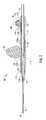
- FIG. 1is a perspective view of one embodiment of the presently disclosed safety needle with a retraction mechanism that employs a constant force spring with a needle in an extended position;
- FIG. 2is a perspective view of the safety needle shown in FIG. 1 with the needle in a retracted position;
- FIG. 3is a perspective view of the safety needle shown in FIG. 1 with a safety sheath positioned about the needle;
- FIG. 4is a perspective view of the safety needle shown in FIG. 3 with parts separated;
- FIG. 5is a perspective view of a hub of the safety needle shown in FIG. 1 ;
- FIG. 6is a top cross-sectional view of the safety needle shown in FIG. 1 with the needle in the extended position;
- FIG. 7is a side cross-sectional view of the safety needle shown in FIG. 6 with the needle in the extended position;
- FIG. 8Ais an enlarged view of the indicated area of detail shown in FIG. 7 ;
- FIG. 8Bis a side perspective cutaway view of a distal portion of the constant force spring positioned above the proximal portion of the hub of the safety needle shown in FIG. 1 .
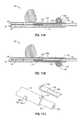
- FIG. 9is a top cross-sectional view of the safety needle shown in FIG. 1 with the needle nearing the fully retracted position;
- FIG. 10Ais a side view illustrating the constant force spring shown in FIG. 8A coiled around a suitable drum;
- FIG. 10Bis a side view illustrating the constant force spring shown in FIG. 8A coiled around itself;
- FIG. 10Cis a top view illustrating the constant force spring shown in FIG. 8B with two apertures;
- FIG. 11Ais a side cross sectional view of the safety needle shown in FIG. 9 with the needle in the fully retracted position;
- FIG. 11Bis a side cross sectional view of a safety needle with the needle in the fully retracted position and the spring located on a bottom side of the body in accordance with another embodiment of the present disclosure
- FIG. 11Cis a side perspective cutaway view of a distal portion of the constant force spring in accordance with another embodiment of the present disclosure.
- FIG. 12is a perspective view of the safety needle shown in FIG. 1 with the needle in the extended position inserted into the arm of a patient.
- proximalrefers to a location on the device closer to the user or operator, i.e. surgeon or physician
- distalrefers to a location on the device further away from the user.
- the present disclosureprovides a spring biased retraction mechanism that includes a spring operatively connected to a hub of a safety needle.
- the springis configured to provide a constant force throughout retraction of the needle device.
- the spring employedis a constant force spring.
- Safety needle 10is of the type generally used during intravenous procedures to insert or withdraw fluid from the body of a patient.
- safety needle 10includes an elongated tubular housing or body 12 , a needle hub 14 and a hollow needle or cannula 16 .
- Needle 16extends distally from hub 14 and has a sharp tissue penetrating tip 18 at a distal end 20 of needle 16 .
- Needle 16is supported on and movable with hub 14 in relation to the body 12 from an extended position ( FIG. 1 ) to a retracted position ( FIG. 9 ).
- needle 16In the retracted position, needle 16 is positioned within body 12 to shield a user from sharp tip 18 of needle 16 .
- a fluid tube 22extends from a proximal end of hub 14 through a proximal end of body 12 and is in fluid communication with needle 16 through hub 14 ( FIG. 6 ). Fluid tube 22 may be transparent.
- Safety needle 10includes retraction mechanism 24 to move needle 16 from the extended position to the retracted position.
- a release member 26 of retraction mechanism 24enables a user to actuate retraction mechanism 24 as will be described in further detail below.
- Safety needle 10optionally includes a dorsal fin 28 to facilitate manipulation of safety needle 10 by a user during insertion or withdrawal of needle 16 from a patient.
- Dorsal fin 28may be integrally formed with release member 26 or, alternatively, can be affixed to, or integral with, body 12 (renumbered fin 30 to 28 in FIG. 2 ).
- Safety needle 10also includes a pair of wings 30 , 32 which stabilize safety needle 10 against the body of the patient.
- Wings 30 , 32may be either flexible or rigid and may be formed separately from, or integral with, elongate tubular member 12 .
- One or both of wings 30 , 32may be used to facilitate grasping of safety needle 10 during insertion and withdrawal of needle 16 from the body of a patient.
- safety needle 10is illustrated with needle 16 in the retracted position.
- needle 16In the retracted position, needle 16 is safely contained within a bore 34 of body 12 .
- body 12In the retracted position, body 12 minimizes the risk of needle stick injury to the user as will be described in more detail hereinbelow.
- safety needle 10is illustrated with a safety sheath 36 positioned over needle 16 .
- Safety sheath 36includes a bore 38 which is dimensioned to receive needle 16 .
- Safety sheath 36is designed to protect a user from needle stick injury prior to use of safety needle 10 .
- Safety sheath 36may include a ribbed outer surface 40 to facilitate grasping and removal of safety sheath 36 from body 12 by the user. It is contemplated that safety needle 10 will be shipped with safety sheath 36 positioned over needle 16 to prevent needlestick injury to the user prior to its use in a medical procedure.
- dorsal fin 28may also be provided with a ribbed outer surface 42 to provide a secure grasping surface to be gripped by the user. It is contemplated herein that safety needle 10 may be provided with other textured or ribbed services to facilitate manipulation by the user, e.g., knurled, grooved, etc.
- proximal end 44 of needle 16extends through bore 34 of elongate body 12 and is affixed to a distal end 46 of hub 14 .
- needle 16is of the type used during intravenous procedures and includes a throughbore 48 for the transmission of fluids.
- Hub 14similarly includes a throughbore 50 for transmission of fluids between needle 16 and fluid tube 22 .
- a first end 52 of fluid tube 22is affixed over a stepped down portion 54 formed at a proximal end 56 of hub 14 .
- safety needle 10includes a retraction mechanism 24 to retract needle 16 into through bore 34 of body 12 to prevent needlestick injury to the user.
- Retraction mechanism 24includes a spring 140 which is positioned proximally within a cavity 144 defined in body 12 .
- Spring 140is configured to engage one or more protrusions 60 formed on hub 14 to bias hub 14 , and thus needle 16 , proximally within body 12 in a manner described in more detail hereinbelow.
- fastening techniquescan be used to fasten spring 140 to hub 14 , e.g., pins, screws, moldings, rivets etc.
- release member 26includes a bridge 62 having a first arm 64 and a second arm 66 positioned on opposite sides of bridge 62 .
- Arms 64 and 66are flexible about bridge 62 .
- Arm 64includes a proximal arm section 68 and arm 66 includes a proximal arm section 70 ( FIG. 9 ).
- Proximal arm sections 68 and 70are configured to be grasped by the user in order to actuate release member 26 .
- Proximal arm sections 68 , 70include ribbed surfaces 72 , 74 respectively, to facilitate grasping by the user.
- Arms 64 , 66include distal arm portions 76 , 78 , respectively which are configured to engage hub 14 and retain hub 14 in an advanced or a distal most position within body 12 against the bias of spring 140 .
- distal arm portion 76includes a lip 80
- distal arm portion 78includes a lip 82 .
- Distal arms 76 and 78extend through a pair of cut outs 84 , 86 ( 86 is now shown) ( FIGS. 4 and 9 ) formed in opposite sides of body 12 such that lips 80 , 82 project into bore 34 of body 12 .
- Release member 26is supported on body 12 in snap fit fashion.
- a pair of notches 88 , 90is formed on opposite sides of body 12 to retain release member 26 thereon and to provide pivot points for arms 64 , 66 .
- hub 14is provided with stop structure 92 which is positioned to engage lips 80 , 82 of arm portions 76 and 78 such that lips 80 , 82 retain hub 14 in an extended position within body 12 against the bias of spring 140 .
- Hub 14is provided with one or more protrusions 60 (two protrusions are shown).
- protrusions 60are provided to engage a distal end of spring 140 in order to bias hub 14 towards the retracted position.
- Protrusions 60are configured and dimensioned to be received in one or more corresponding apertures 148 located on a distal end of spring 140 such that hub 14 and spring 140 are maintained in a connected condition, e.g., press fit.
- hub 14may have a slit or other suitable structure (not explicitly shown) configured to engage with spring 140 .
- hub 14 and spring 140may be connected by way of stamping, overmolding, injection molding and so on. The manner in which spring 140 and hub 14 are connected is not critical to the operation of safety needle 10 , as described herein.
- stop structure 92 on hub 14includes a first engagement block 100 and a second engagement block 102 provided on an opposite side of hub 14 .
- Engagement blocks 100 , 102are provided with proximally facing engaging surfaces 104 and 106 .
- engaging surfaces 104 and 106 of blocks 100 and 102 of hub 14are engaged by a lips 80 , 82 of arms 64 and 66 , respectively, of release member 26 to retain hub 14 in the advanced position.
- Proximally facing engaging surfaces 104 and 106provide the further function of limiting the extent of retraction of hub 14 within body 12 in a manner described in more detail hereinbelow.
- blocks 100 and 102could be removed and a collar or other projection configuration (not explicitly shown) may function to engage lips 80 , 82 of release member 26 and limit retraction of hub 14 within body 12 .
- arms 64 and 66are pivotally mounted to body 12 .
- arms 64 and 66are provided with pivot projections 116 and 118 .
- Pivot projections 116 , 118are configured to reside within notches 88 and 90 ( FIG. 4 ) formed in body 12 .
- Pivot projections 116 , 118secure release member 26 both circumferentially and longitudinally to body 12 .
- spring 140is configured to provide a substantially constant force to hub 14 while hub 14 moves from the extended or advanced position to the retracted position.
- spring 140is a constant force extension spring.
- Constant force extension springstypically are prestressed into flat strips of spring material that are formed into constant radius coils. These types of springs produce constant force which makes them suitable for use with the retraction mechanism 24 of the present disclosure.
- Suitable commercially available constant force extension springsare manufactured and sold by AMETEK, Inc. under the trademark NEG'ATOR®.
- spring 140is coiled around a drum 142 ( FIG. 10A ).
- spring 140may be coiled around itself ( FIG. 10B ).
- Spring 140may be made from any suitable material including metal, metal alloys, plastic, and so on.
- spring 140is made from type 301 stainless steel. Prior to formation, spring 140 may be annealed to improve the cold working properties of the steel. Spring 140 may also be treated chemically or otherwise.
- Cavity 144may be formed separately from, or integral with, body 12 . Cavity 144 is configured and dimensioned such that spring 140 is free to recoil (retraction) as needed. To this end, an arcuate surface forms a cradle 146 that extends into cavity 144 of body 12 . Cavity 144 is provided with an opening configured such that spring 140 may extend within body 12 . Cradle 146 provides support for spring 140 to facilitate recoiling of spring 140 . Cavity 144 may include one or more brackets and/or axels that extend laterally within cavity 144 (not explicitly shown).
- the brackets and/or axelsprovide additional support for spring 140 . Additionally, the brackets and/or axels may be used to support spring 140 in an elevated or suspended configuration, which may facilitate recoiling of the spring 140 . In this manner, cradle 146 may be eliminated.
- spring 140is operatively connected to hub 14 by engagement of protrusions 60 of hub 14 within apertures 148 of spring 140 as discussed above.
- Apertures 148are disposed on spring 140 such that apertures 148 align along the same central axis as protrusions 60 .
- Apertures 148have diameters A 1 ( FIG. 10C ), that are large enough to fit around protrusions 60 such that spring 140 remains connected to hub 14 during advancement and retraction of hub 14 .
- protrusions 60may extend through and beyond apertures 148 to enable heat staking.
- spring 140may vary depending on, inter alia, space, life cycle, load, and/or operation requirements of the surgical needle 10 that spring 140 is configured for use with.
- body 12has a proximal facing surface 126 within bore 34 which cooperates with proximal facing surfaces 104 and 106 of engagement blocks 100 , 102 to limit the proximal travel of hub 14 within body 12 .
- hub 14In order to observe the flow of fluids through hub 14 , hub 14 is provided with a transparent zone 128 ( FIGS. 4 and 7 ) at a distal end adjacent the proximal end of needle 16 (zone 128 was moved to right in drawings as suggested). By observing the flow of fluid through transparent zone 128 , the user can confirm that needle 16 has been properly positioned within the body.
- hub 14 and/or body 12may be made from a transparent material.
- at least a top side of body 12may be provided with a transparent zone, or aperture, 128 a and configured for observation of fluid flow through tube 22 and/or hub 14 .
- spring biased retraction mechanism 24may be located on the bottom side ( FIG.
- Spring 140may possess a light colored surface finish (e.g. white) to provide a contrasting background for observing fluid flow through tube 22 and/or hub 14 . Additionally, especially with spring based mechanism 24 located on the top side of body 12 , spring 140 may include at least one additional aperture, slot, or void 148 a located along a length thereof ( FIG. 11C ) to facilitate observation of fluid flow through tube 22 and/or hub 14 .
- safety needle 10is provided with safety sheath 36 positioned over needle 16 to prevent any needlestick injury to the user during shipping, unpackaging and immediately prior to use of safety needle 10 .
- ribbed outer surface 40 of safety sheath 36is grasped and safety sheath 36 is removed from needle 16 (Referential numerals 36 , 40 now conform with drawings).
- needle 16in the initial position, needle 16 is in the advanced position and extends distally from body 12 .
- Spring 140is in an extended uncoiled condition along inner surface 122 of body 12 .
- Hub 14is retained in the advanced position by engagement of lips 80 , 82 with proximal facing surfaces 104 and 106 of engagement blocks 100 , 102 ( FIG. 6 ).
- safety needle 10is inserted in normal intravenous fashion into a patient such that sharp tip 18 penetrates a vein for infusion, injection and/or removal of fluids from a patient (See FIG. 12 ).
- the usermay grasp dorsal fin 28 which is provided to facilitate manipulation of safety needle 10 .
- one or both wings 30 and 32may be grasped to facilitate insertion of safety needle 10 into a vein.
- the usercan leave needle 16 within the vein of the patient or remove needle 16 from the body of the patient. Again, dorsal fin 28 or one or more wings 30 , 32 can be grasped to facilitate removal of safety needle 10 from the body of the patient.
- the usermay actuate retraction mechanism 24 to retract sharp tip 18 of needle 16 safely within bore 34 of body 12 .
- Retraction mechanism 24is actuated by squeezing proximal arm 68 and proximal arm 70 inwardly towards body 12 in the direction indicated by arrows A in FIG. 9 to rotate arms 64 and 66 about pivot points 116 , 118 .
- arms 64 and 66moves distal arms 76 and 78 radially outwardly in the direction indicated by arrows B in FIG. 9 .
- lips 80 and 82disengage from proximal facing surfaces 104 and 106 of engagement blocks 100 , 102 .
- hub 14is free to move in a proximal direction in response to the bias of spring 140 .
- spring 140is a constant force spring
- hub 14will be provided with a constant force throughout retraction. In this manner, retraction of sharp tip 18 from the vein of the patient will occur with minimal trauma and/or proximal movement of needle 16 will result in minimal splatter.
- Hub 14will move proximally until proximally facing surfaces 104 and 106 engage proximal inner surface 126 of tubular body 12 . This prevents any further proximal retraction of hub 14 relative to body 12 .
- sharp tip 18 of needle 16is safely contained within bore 34 of body 12 to prevent needlestick injury to the user.
- safety needle 10may include a lockout structure which retains needle 16 in a retracted position within body 12 and prevents re-advancement thereof.
- retraction mechanismincluding a constant force spring is described in association with a winged intravenous needle assembly, it is envisioned that the retraction mechanism could be incorporated into any existing retractable needle assembly including retractable needle syringes. Therefore, the above description should not be construed as limiting, but merely as exemplifications of particular embodiments. Those skilled in the art will envision other modifications within the scope and spirit of the claims appended hereto.
Landscapes
- Health & Medical Sciences (AREA)
- Life Sciences & Earth Sciences (AREA)
- Animal Behavior & Ethology (AREA)
- Engineering & Computer Science (AREA)
- Anesthesiology (AREA)
- Biomedical Technology (AREA)
- Heart & Thoracic Surgery (AREA)
- Hematology (AREA)
- General Health & Medical Sciences (AREA)
- Public Health (AREA)
- Veterinary Medicine (AREA)
- Pulmonology (AREA)
- Biophysics (AREA)
- Vascular Medicine (AREA)
- Infusion, Injection, And Reservoir Apparatuses (AREA)
Abstract
Description
Claims (13)
Priority Applications (1)
| Application Number | Priority Date | Filing Date | Title |
|---|---|---|---|
| US12/409,055US9259533B2 (en) | 2008-03-31 | 2009-03-23 | Safety needle with spring biased retraction mechanism |
Applications Claiming Priority (2)
| Application Number | Priority Date | Filing Date | Title |
|---|---|---|---|
| US4102108P | 2008-03-31 | 2008-03-31 | |
| US12/409,055US9259533B2 (en) | 2008-03-31 | 2009-03-23 | Safety needle with spring biased retraction mechanism |
Publications (2)
| Publication Number | Publication Date |
|---|---|
| US20090247952A1 US20090247952A1 (en) | 2009-10-01 |
| US9259533B2true US9259533B2 (en) | 2016-02-16 |
Family
ID=41118273
Family Applications (1)
| Application Number | Title | Priority Date | Filing Date |
|---|---|---|---|
| US12/409,055Active2030-02-09US9259533B2 (en) | 2008-03-31 | 2009-03-23 | Safety needle with spring biased retraction mechanism |
Country Status (1)
| Country | Link |
|---|---|
| US (1) | US9259533B2 (en) |
Cited By (7)
| Publication number | Priority date | Publication date | Assignee | Title |
|---|---|---|---|---|
| US20150367104A1 (en)* | 2013-02-05 | 2015-12-24 | Vigmed Ab | Needle assembly |
| USD828653S1 (en)* | 2016-12-14 | 2018-09-11 | Brandon Penland | Treatment applicator |
| US10086170B2 (en) | 2014-02-04 | 2018-10-02 | Icu Medical, Inc. | Self-priming systems and methods |
| US10159818B2 (en) | 2010-05-19 | 2018-12-25 | Tangent Medical Technologies, Inc. | Safety needle system operable with a medical device |
| US10569069B2 (en) | 2016-12-14 | 2020-02-25 | Combat Comb, Llc | Applicator for treatments applied to animal skin |
| US10569057B2 (en) | 2010-05-19 | 2020-02-25 | Tangent Medical Technologies, Inc. | Integrated vascular delivery system |
| US10668252B2 (en) | 2009-08-14 | 2020-06-02 | The Regents Of The University Of Michigan | Integrated vascular delivery system |
Families Citing this family (4)
| Publication number | Priority date | Publication date | Assignee | Title |
|---|---|---|---|---|
| US20110306933A1 (en)* | 2010-06-11 | 2011-12-15 | Ilija Djordjevic | Safety cannula with automatic retractable needle |
| WO2013173617A1 (en) | 2012-05-16 | 2013-11-21 | The Seaberg Company, Inc. | Safety needle |
| USD787665S1 (en)* | 2013-11-28 | 2017-05-23 | Pengfei Wu | Curved hypodermic needle |
| WO2015087939A1 (en)* | 2013-12-11 | 2015-06-18 | オリンパス株式会社 | Endoscope treatment instrument |
Citations (91)
| Publication number | Priority date | Publication date | Assignee | Title |
|---|---|---|---|---|
| US4183246A (en) | 1978-06-08 | 1980-01-15 | Reynolds Steven C | Insulation presence sensing probe |
| US4676783A (en) | 1985-09-03 | 1987-06-30 | The University Of Virginia Alumni Patents Foundation | Retractable safety needle |
| US4690675A (en) | 1984-11-19 | 1987-09-01 | William Katz | Intravenous needle assembly |
| US4747831A (en) | 1987-04-29 | 1988-05-31 | Phase Medical, Inc. | Cannula insertion set with safety retracting needle |
| US4781692A (en) | 1985-09-03 | 1988-11-01 | The University Of Virginia Alumni Patents Foundation | Retractable safety needles |
| US4813426A (en) | 1987-11-09 | 1989-03-21 | Habley Medical Technology Corporation | Shielded safety syringe having a retractable needle |
| US4820282A (en) | 1986-10-20 | 1989-04-11 | City Of Hope National Medical Center | Sheath for butterfly needles |
| US4900311A (en) | 1988-12-06 | 1990-02-13 | Lawrence Stern | Hypodermic syringe |
| US4900307A (en) | 1987-04-29 | 1990-02-13 | Kulli John C | Safety retracting needle for use with syringe |
| US4973316A (en) | 1990-01-16 | 1990-11-27 | Dysarz Edward D | One handed retractable safety syringe |
| US4994034A (en) | 1989-07-11 | 1991-02-19 | Botich Michael J | Retractable needle hypodermic syringe system |
| US5084030A (en) | 1985-07-29 | 1992-01-28 | National Research Development Corporation | Safety device for hypodermic needle or the like |
| US5085639A (en) | 1988-03-01 | 1992-02-04 | Ryan Medical, Inc. | Safety winged needle medical devices |
| US5088982A (en) | 1988-03-01 | 1992-02-18 | Ryan Medical, Inc. | Safety winged needle medical devices |
| US5108376A (en) | 1990-11-14 | 1992-04-28 | Safetyject | Retractable intravenous needle assembly |
| US5114410A (en) | 1990-01-17 | 1992-05-19 | Jaime Caralt Batlle | Disposable hypodermic syringe |
| US5120320A (en) | 1991-02-13 | 1992-06-09 | Becton, Dickinson And Company | I.V. infusion or blood collection assembly with automatic safety feature |
| US5125414A (en) | 1990-01-16 | 1992-06-30 | Dysarz Edward D | Trap in barrel one handed retracted blood sampling device |
| US5129884A (en) | 1990-01-16 | 1992-07-14 | Dysarz Edward D | Trap in barrel one handed retracted intervenous catheter device |
| US5147327A (en) | 1990-01-10 | 1992-09-15 | Johnson Gerald W | Hypodermic needle with protective sheath |
| US5176655A (en) | 1990-11-08 | 1993-01-05 | Mbo Laboratories, Inc. | Disposable medical needle and catheter placement assembly having full safety enclosure means |
| US5188599A (en) | 1989-07-11 | 1993-02-23 | Med-Design, Inc. | Retractable needle system |
| US5188119A (en) | 1989-08-03 | 1993-02-23 | Sherwood Medical Company | Blood collection tube holder safety guard |
| US5192275A (en) | 1991-09-18 | 1993-03-09 | Becton, Dickinson And Company | IV infusion or blood collection guard assembly |
| US5226894A (en) | 1990-09-11 | 1993-07-13 | Sterling Winthrop Inc. | Safety syringe assembly with radially deformable body |
| US5232456A (en) | 1991-05-30 | 1993-08-03 | Gonzalez Antonio S | Protector for self-retractile hypodermic needles |
| US5267961A (en) | 1991-04-03 | 1993-12-07 | Shaw Thomas J | Nonreusable syringe with safety indicator |
| US5273540A (en) | 1991-04-26 | 1993-12-28 | Luther Medical Products | Nonreusable needle and catheter assembly |
| US5318538A (en) | 1992-02-03 | 1994-06-07 | Timothy Kershenstine | Self-locking safety syringe |
| US5330438A (en) | 1993-10-08 | 1994-07-19 | Gollobin Peter J | Protective sheath for butterfly needles and IV infusion set and sheath assembly |
| US5338303A (en) | 1992-09-08 | 1994-08-16 | Design And Engineering Associates | Safety syringes |
| US5376075A (en) | 1993-08-31 | 1994-12-27 | Haughton; Victor M. | Catheter sharp retraction system |
| US5385551A (en) | 1993-09-22 | 1995-01-31 | Shaw; Thomas J. | Nonreusable medical device with front retraction |
| US5389076A (en) | 1994-04-05 | 1995-02-14 | Shaw; Thomas J. | Single use medical device with retraction mechanism |
| US5407431A (en) | 1989-07-11 | 1995-04-18 | Med-Design Inc. | Intravenous catheter insertion device with retractable needle |
| US5409461A (en) | 1993-09-28 | 1995-04-25 | Becton Dickinson And Company | Catheter introducer assembly with needle shielding device |
| US5423758A (en) | 1993-12-16 | 1995-06-13 | Shaw; Thomas J. | Retractable fluid collection device |
| US5478316A (en)* | 1994-02-02 | 1995-12-26 | Becton, Dickinson And Company | Automatic self-injection device |
| US5501675A (en) | 1994-12-27 | 1996-03-26 | Becton, Dickinson And Company | Safety catheter assembly having safety stop push button |
| US5538508A (en) | 1992-07-31 | 1996-07-23 | Steyn; Ricardo S. | Needle protective device |
| US5549571A (en) | 1995-04-18 | 1996-08-27 | Sak; Robert F. | Butterfly assembly with retractable needle cannula |
| US5554130A (en) | 1995-05-17 | 1996-09-10 | Creative Bio Tech, Inc. | Stick-free syringe and associated methods |
| US5562629A (en) | 1993-08-31 | 1996-10-08 | Haughton; Victor M. | Catheter placement system utilizing a handle, a sharp, and a releasable retainer mechanism providing retraction of the sharp upon disengagement of the catheter from the handle |
| US5562634A (en) | 1993-09-16 | 1996-10-08 | Giuseppe Pilo | Intravenous catheter with automatically retracting needle-guide |
| US5573510A (en) | 1994-02-28 | 1996-11-12 | Isaacson; Dennis R. | Safety intravenous catheter assembly with automatically retractable needle |
| US5575777A (en) | 1993-11-15 | 1996-11-19 | Becton Dickinson And Company | Retractable needle cannula insertion set with refinements to better control leakage, retraction speed and reuse |
| US5578011A (en) | 1995-05-11 | 1996-11-26 | Shaw; Thomas J. | Tamperproof retractable syringe |
| US5591138A (en) | 1995-08-10 | 1997-01-07 | Vaillancourt; Vincent L. | Protected needle assembly |
| US5632733A (en) | 1995-05-11 | 1997-05-27 | Shaw; Thomas J. | Tamperproof retractable syringe |
| US5676658A (en) | 1995-03-07 | 1997-10-14 | Becton Dickinson And Company | Catheter-advancement actuated needle retraction system |
| US5695475A (en) | 1995-12-13 | 1997-12-09 | Best, Jr.; Lester | Syringe apparatus |
| US5746215A (en) | 1996-11-01 | 1998-05-05 | U.S. Medical Instruments, Inc. | IV infusion or collection device with extendable and retractable needle |
| US5779679A (en) | 1997-04-18 | 1998-07-14 | Shaw; Thomas J. | Winged IV set with retractable needle |
| US5810775A (en) | 1997-05-23 | 1998-09-22 | Shaw; Thomas J. | Cap operated retractable medical device |
| US5928199A (en) | 1996-09-20 | 1999-07-27 | Nissho Corporation | Winged needle assembly |
| US5931815A (en) | 1997-08-22 | 1999-08-03 | Liu; Wen-Neng | Multifunctional safety infusion set with injection needle retractable in a wing-equipped sheath |
| US5951525A (en) | 1998-02-10 | 1999-09-14 | Specialized Health Products, Inc. | Manual safety medical needle apparatus and methods |
| US5997512A (en) | 1998-03-04 | 1999-12-07 | Shaw; Thomas J. | Retractable dental syringe |
| US6015438A (en) | 1997-11-14 | 2000-01-18 | Retractable Technologies Inc. | Full displacement retractable syringe |
| US6077244A (en) | 1998-04-30 | 2000-06-20 | Mdc Investment Holdings, Inc. | Catheter insertion device with retractable needle |
| US6080137A (en) | 1997-01-08 | 2000-06-27 | Vadus, Inc. | Needle protector |
| US6090078A (en) | 1997-09-30 | 2000-07-18 | Becton, Dickinson And Company | Dampening devices and methods for needle retracting safety vascular access devices |
| US6096005A (en) | 1989-07-11 | 2000-08-01 | Mdc Investment Holdings, Inc. | Retractable needle medical devices |
| US6210371B1 (en) | 1999-03-30 | 2001-04-03 | Retractable Technologies, Inc. | Winged I.V. set |
| US6221055B1 (en) | 1998-03-04 | 2001-04-24 | Retractable Technologies, Inc. | Retractable dental syringe |
| USRE37439E1 (en) | 1990-05-09 | 2001-11-06 | Safety Syringes, Inc. | Disposable self-shielding aspirating syringe |
| US6494863B1 (en) | 2001-10-15 | 2002-12-17 | Retractable Technologies, Inc. | One-use retracting syringe with positive needle retention |
| US6524276B1 (en) | 2000-06-05 | 2003-02-25 | Mdc Investment Holdings, Inc. | Fluid collection device having tilting retractable needle |
| US20030040717A1 (en) | 2001-08-09 | 2003-02-27 | Becton, Dickinson And Company, A New Jersey Corporation | Retracting needle safety device |
| US6547762B1 (en) | 1999-05-13 | 2003-04-15 | Mdc Investment Holdings, Inc. | Retractable needle medical device |
| US20030078540A1 (en)* | 2001-10-24 | 2003-04-24 | Becton, Dickinson And Company | Retractable needle assembly |
| US20030093035A1 (en) | 1999-12-23 | 2003-05-15 | Owais Mohammed | Hypodermic syringe needle assembly and method of making the same |
| US6572584B1 (en) | 2000-08-07 | 2003-06-03 | Retractable Technologies, Inc. | Retractable syringe with reduced retraction force |
| US6620136B1 (en) | 1999-02-18 | 2003-09-16 | Medsafe Technologies, Llc | Retractable I-V catheter placement device |
| US20030199830A1 (en) | 2002-04-17 | 2003-10-23 | Nguyen Steven Huu | Retractable safety infusion needle |
| US6641555B1 (en) | 1997-11-12 | 2003-11-04 | Mdc Investment Holdings, Inc. | Fluid collection device with captured retractable needle |
| US20030220619A1 (en) | 1997-03-26 | 2003-11-27 | Polidoro John M. | Parenteral fluid transfer apparatus |
| US6673047B2 (en) | 2001-01-05 | 2004-01-06 | Becton, Dickinson And Company | Blood collection set |
| US6743186B2 (en) | 2001-01-05 | 2004-06-01 | Becton, Dickinson And Company | Blood collection assembly |
| US6773419B2 (en) | 2001-01-05 | 2004-08-10 | Jamieson William Maclean Crawford | Blood collection set |
| US6786875B2 (en) | 2000-04-18 | 2004-09-07 | Mdc Investement Holdings, Inc. | Medical device with shield having a retractable needle |
| US20040193110A1 (en) | 2002-02-07 | 2004-09-30 | Lucio Giambattista | Pen needle and safety shield system |
| US20040267200A1 (en) | 2003-06-27 | 2004-12-30 | Carlyon James L. | Safety needle shield apparatus |
| US6860872B2 (en) | 2001-08-20 | 2005-03-01 | Joseph Von Teichert | Safety syringe/catheter |
| US6905478B2 (en) | 2001-03-14 | 2005-06-14 | Glenord Pty. Ltd. | Non-reusable syringe |
| US6929624B1 (en)* | 2003-02-03 | 2005-08-16 | Gil Del Castillo | Intravenous catheter housing with retractable needle |
| US6945960B2 (en) | 1999-11-29 | 2005-09-20 | Mdc Investment Holdings, Inc. | Combination safety needle assembly and medical apparatus |
| US6972002B2 (en) | 2000-04-28 | 2005-12-06 | Specialized Health Products, Inc. | Passively activated safety shield for a catheter insertion needle |
| US6976976B2 (en)* | 2002-03-27 | 2005-12-20 | Safety Syringes, Inc. | Syringe with needle guard injection device |
| US7422572B2 (en) | 2001-02-21 | 2008-09-09 | Serpomed Ltd. | Compact catheter insertion apparatus |
| US7611486B2 (en)* | 2005-09-22 | 2009-11-03 | Tyco Healthcare Group Lp | Needle retraction structure |
Family Cites Families (1)
| Publication number | Priority date | Publication date | Assignee | Title |
|---|---|---|---|---|
| US5537508A (en)* | 1993-03-22 | 1996-07-16 | Applied Materials, Inc. | Method and dry vapor generator channel assembly for conveying a liquid from a liquid source to a liquid vaporizer with minimal liquid stagnation |
- 2009
- 2009-03-23USUS12/409,055patent/US9259533B2/enactiveActive
Patent Citations (98)
| Publication number | Priority date | Publication date | Assignee | Title |
|---|---|---|---|---|
| US4183246A (en) | 1978-06-08 | 1980-01-15 | Reynolds Steven C | Insulation presence sensing probe |
| US4690675A (en) | 1984-11-19 | 1987-09-01 | William Katz | Intravenous needle assembly |
| US5084030A (en) | 1985-07-29 | 1992-01-28 | National Research Development Corporation | Safety device for hypodermic needle or the like |
| US4676783A (en) | 1985-09-03 | 1987-06-30 | The University Of Virginia Alumni Patents Foundation | Retractable safety needle |
| US4781692A (en) | 1985-09-03 | 1988-11-01 | The University Of Virginia Alumni Patents Foundation | Retractable safety needles |
| US4820282A (en) | 1986-10-20 | 1989-04-11 | City Of Hope National Medical Center | Sheath for butterfly needles |
| US4747831A (en) | 1987-04-29 | 1988-05-31 | Phase Medical, Inc. | Cannula insertion set with safety retracting needle |
| US4900307A (en) | 1987-04-29 | 1990-02-13 | Kulli John C | Safety retracting needle for use with syringe |
| US4813426A (en) | 1987-11-09 | 1989-03-21 | Habley Medical Technology Corporation | Shielded safety syringe having a retractable needle |
| US5085639A (en) | 1988-03-01 | 1992-02-04 | Ryan Medical, Inc. | Safety winged needle medical devices |
| US5088982A (en) | 1988-03-01 | 1992-02-18 | Ryan Medical, Inc. | Safety winged needle medical devices |
| US4900311A (en) | 1988-12-06 | 1990-02-13 | Lawrence Stern | Hypodermic syringe |
| US5188599A (en) | 1989-07-11 | 1993-02-23 | Med-Design, Inc. | Retractable needle system |
| US5407431A (en) | 1989-07-11 | 1995-04-18 | Med-Design Inc. | Intravenous catheter insertion device with retractable needle |
| US6179812B1 (en) | 1989-07-11 | 2001-01-30 | Mdc Investment Holdings, Inc. | Retractable needle medical devices |
| US4994034A (en) | 1989-07-11 | 1991-02-19 | Botich Michael J | Retractable needle hypodermic syringe system |
| US6096005A (en) | 1989-07-11 | 2000-08-01 | Mdc Investment Holdings, Inc. | Retractable needle medical devices |
| US5188119A (en) | 1989-08-03 | 1993-02-23 | Sherwood Medical Company | Blood collection tube holder safety guard |
| US5147327A (en) | 1990-01-10 | 1992-09-15 | Johnson Gerald W | Hypodermic needle with protective sheath |
| US4973316A (en) | 1990-01-16 | 1990-11-27 | Dysarz Edward D | One handed retractable safety syringe |
| US5129884A (en) | 1990-01-16 | 1992-07-14 | Dysarz Edward D | Trap in barrel one handed retracted intervenous catheter device |
| US5125414A (en) | 1990-01-16 | 1992-06-30 | Dysarz Edward D | Trap in barrel one handed retracted blood sampling device |
| US5114410A (en) | 1990-01-17 | 1992-05-19 | Jaime Caralt Batlle | Disposable hypodermic syringe |
| USRE37439E1 (en) | 1990-05-09 | 2001-11-06 | Safety Syringes, Inc. | Disposable self-shielding aspirating syringe |
| US5226894A (en) | 1990-09-11 | 1993-07-13 | Sterling Winthrop Inc. | Safety syringe assembly with radially deformable body |
| US5176655A (en) | 1990-11-08 | 1993-01-05 | Mbo Laboratories, Inc. | Disposable medical needle and catheter placement assembly having full safety enclosure means |
| US5395347A (en) | 1990-11-08 | 1995-03-07 | Mbo Laboratories, Inc. | Safe blood collection system |
| US5108376A (en) | 1990-11-14 | 1992-04-28 | Safetyject | Retractable intravenous needle assembly |
| US5120320A (en) | 1991-02-13 | 1992-06-09 | Becton, Dickinson And Company | I.V. infusion or blood collection assembly with automatic safety feature |
| US5267961A (en) | 1991-04-03 | 1993-12-07 | Shaw Thomas J | Nonreusable syringe with safety indicator |
| US5273540A (en) | 1991-04-26 | 1993-12-28 | Luther Medical Products | Nonreusable needle and catheter assembly |
| US5232456A (en) | 1991-05-30 | 1993-08-03 | Gonzalez Antonio S | Protector for self-retractile hypodermic needles |
| US5192275A (en) | 1991-09-18 | 1993-03-09 | Becton, Dickinson And Company | IV infusion or blood collection guard assembly |
| US5318538A (en) | 1992-02-03 | 1994-06-07 | Timothy Kershenstine | Self-locking safety syringe |
| US5538508A (en) | 1992-07-31 | 1996-07-23 | Steyn; Ricardo S. | Needle protective device |
| US5338303A (en) | 1992-09-08 | 1994-08-16 | Design And Engineering Associates | Safety syringes |
| US5562629A (en) | 1993-08-31 | 1996-10-08 | Haughton; Victor M. | Catheter placement system utilizing a handle, a sharp, and a releasable retainer mechanism providing retraction of the sharp upon disengagement of the catheter from the handle |
| US5376075A (en) | 1993-08-31 | 1994-12-27 | Haughton; Victor M. | Catheter sharp retraction system |
| US5562634A (en) | 1993-09-16 | 1996-10-08 | Giuseppe Pilo | Intravenous catheter with automatically retracting needle-guide |
| US5385551A (en) | 1993-09-22 | 1995-01-31 | Shaw; Thomas J. | Nonreusable medical device with front retraction |
| US5409461A (en) | 1993-09-28 | 1995-04-25 | Becton Dickinson And Company | Catheter introducer assembly with needle shielding device |
| US5330438A (en) | 1993-10-08 | 1994-07-19 | Gollobin Peter J | Protective sheath for butterfly needles and IV infusion set and sheath assembly |
| US5575777A (en) | 1993-11-15 | 1996-11-19 | Becton Dickinson And Company | Retractable needle cannula insertion set with refinements to better control leakage, retraction speed and reuse |
| US5423758A (en) | 1993-12-16 | 1995-06-13 | Shaw; Thomas J. | Retractable fluid collection device |
| US5478316A (en)* | 1994-02-02 | 1995-12-26 | Becton, Dickinson And Company | Automatic self-injection device |
| US5573510A (en) | 1994-02-28 | 1996-11-12 | Isaacson; Dennis R. | Safety intravenous catheter assembly with automatically retractable needle |
| US6056726A (en) | 1994-02-28 | 2000-05-02 | Isaacson; Dennis Ray | Self-contained safety intravenous catheter insertion device |
| US5389076A (en) | 1994-04-05 | 1995-02-14 | Shaw; Thomas J. | Single use medical device with retraction mechanism |
| US5501675A (en) | 1994-12-27 | 1996-03-26 | Becton, Dickinson And Company | Safety catheter assembly having safety stop push button |
| US6582402B1 (en) | 1995-03-07 | 2003-06-24 | Becton Dickinson And Company | Catheter-advancement actuated needle retraction system |
| US5676658A (en) | 1995-03-07 | 1997-10-14 | Becton Dickinson And Company | Catheter-advancement actuated needle retraction system |
| US5549571A (en) | 1995-04-18 | 1996-08-27 | Sak; Robert F. | Butterfly assembly with retractable needle cannula |
| US5632733A (en) | 1995-05-11 | 1997-05-27 | Shaw; Thomas J. | Tamperproof retractable syringe |
| US5578011A (en) | 1995-05-11 | 1996-11-26 | Shaw; Thomas J. | Tamperproof retractable syringe |
| US5554130A (en) | 1995-05-17 | 1996-09-10 | Creative Bio Tech, Inc. | Stick-free syringe and associated methods |
| US5591138A (en) | 1995-08-10 | 1997-01-07 | Vaillancourt; Vincent L. | Protected needle assembly |
| US5695475A (en) | 1995-12-13 | 1997-12-09 | Best, Jr.; Lester | Syringe apparatus |
| US5928199A (en) | 1996-09-20 | 1999-07-27 | Nissho Corporation | Winged needle assembly |
| US5746215A (en) | 1996-11-01 | 1998-05-05 | U.S. Medical Instruments, Inc. | IV infusion or collection device with extendable and retractable needle |
| US6080137A (en) | 1997-01-08 | 2000-06-27 | Vadus, Inc. | Needle protector |
| US20030220619A1 (en) | 1997-03-26 | 2003-11-27 | Polidoro John M. | Parenteral fluid transfer apparatus |
| US5779679A (en) | 1997-04-18 | 1998-07-14 | Shaw; Thomas J. | Winged IV set with retractable needle |
| US5810775A (en) | 1997-05-23 | 1998-09-22 | Shaw; Thomas J. | Cap operated retractable medical device |
| US5931815A (en) | 1997-08-22 | 1999-08-03 | Liu; Wen-Neng | Multifunctional safety infusion set with injection needle retractable in a wing-equipped sheath |
| US6090078A (en) | 1997-09-30 | 2000-07-18 | Becton, Dickinson And Company | Dampening devices and methods for needle retracting safety vascular access devices |
| US6641555B1 (en) | 1997-11-12 | 2003-11-04 | Mdc Investment Holdings, Inc. | Fluid collection device with captured retractable needle |
| US6015438A (en) | 1997-11-14 | 2000-01-18 | Retractable Technologies Inc. | Full displacement retractable syringe |
| US5951525A (en) | 1998-02-10 | 1999-09-14 | Specialized Health Products, Inc. | Manual safety medical needle apparatus and methods |
| US6221055B1 (en) | 1998-03-04 | 2001-04-24 | Retractable Technologies, Inc. | Retractable dental syringe |
| US5997512A (en) | 1998-03-04 | 1999-12-07 | Shaw; Thomas J. | Retractable dental syringe |
| US6077244A (en) | 1998-04-30 | 2000-06-20 | Mdc Investment Holdings, Inc. | Catheter insertion device with retractable needle |
| US6942652B1 (en) | 1999-02-18 | 2005-09-13 | Medsafe Technologies, Llc | Retractable I-V catheter placement device |
| US6620136B1 (en) | 1999-02-18 | 2003-09-16 | Medsafe Technologies, Llc | Retractable I-V catheter placement device |
| US6210371B1 (en) | 1999-03-30 | 2001-04-03 | Retractable Technologies, Inc. | Winged I.V. set |
| US6547762B1 (en) | 1999-05-13 | 2003-04-15 | Mdc Investment Holdings, Inc. | Retractable needle medical device |
| US6945960B2 (en) | 1999-11-29 | 2005-09-20 | Mdc Investment Holdings, Inc. | Combination safety needle assembly and medical apparatus |
| US20030093035A1 (en) | 1999-12-23 | 2003-05-15 | Owais Mohammed | Hypodermic syringe needle assembly and method of making the same |
| US6786875B2 (en) | 2000-04-18 | 2004-09-07 | Mdc Investement Holdings, Inc. | Medical device with shield having a retractable needle |
| US6972002B2 (en) | 2000-04-28 | 2005-12-06 | Specialized Health Products, Inc. | Passively activated safety shield for a catheter insertion needle |
| US6524276B1 (en) | 2000-06-05 | 2003-02-25 | Mdc Investment Holdings, Inc. | Fluid collection device having tilting retractable needle |
| US6572584B1 (en) | 2000-08-07 | 2003-06-03 | Retractable Technologies, Inc. | Retractable syringe with reduced retraction force |
| US6743186B2 (en) | 2001-01-05 | 2004-06-01 | Becton, Dickinson And Company | Blood collection assembly |
| US6773419B2 (en) | 2001-01-05 | 2004-08-10 | Jamieson William Maclean Crawford | Blood collection set |
| US6673047B2 (en) | 2001-01-05 | 2004-01-06 | Becton, Dickinson And Company | Blood collection set |
| US7422572B2 (en) | 2001-02-21 | 2008-09-09 | Serpomed Ltd. | Compact catheter insertion apparatus |
| US6905478B2 (en) | 2001-03-14 | 2005-06-14 | Glenord Pty. Ltd. | Non-reusable syringe |
| US20030040717A1 (en) | 2001-08-09 | 2003-02-27 | Becton, Dickinson And Company, A New Jersey Corporation | Retracting needle safety device |
| US6860872B2 (en) | 2001-08-20 | 2005-03-01 | Joseph Von Teichert | Safety syringe/catheter |
| US6494863B1 (en) | 2001-10-15 | 2002-12-17 | Retractable Technologies, Inc. | One-use retracting syringe with positive needle retention |
| US20030078540A1 (en)* | 2001-10-24 | 2003-04-24 | Becton, Dickinson And Company | Retractable needle assembly |
| US20040193110A1 (en) | 2002-02-07 | 2004-09-30 | Lucio Giambattista | Pen needle and safety shield system |
| US6976976B2 (en)* | 2002-03-27 | 2005-12-20 | Safety Syringes, Inc. | Syringe with needle guard injection device |
| US6835190B2 (en) | 2002-04-17 | 2004-12-28 | Smiths Medical Asd, Inc. | Retractable safety infusion needle |
| US20030199830A1 (en) | 2002-04-17 | 2003-10-23 | Nguyen Steven Huu | Retractable safety infusion needle |
| US6929624B1 (en)* | 2003-02-03 | 2005-08-16 | Gil Del Castillo | Intravenous catheter housing with retractable needle |
| US20040267200A1 (en) | 2003-06-27 | 2004-12-30 | Carlyon James L. | Safety needle shield apparatus |
| US7037292B2 (en) | 2003-06-27 | 2006-05-02 | Sherwood Services Ag | Safety needle shield apparatus |
| US7611486B2 (en)* | 2005-09-22 | 2009-11-03 | Tyco Healthcare Group Lp | Needle retraction structure |
Cited By (17)
| Publication number | Priority date | Publication date | Assignee | Title |
|---|---|---|---|---|
| US10668252B2 (en) | 2009-08-14 | 2020-06-02 | The Regents Of The University Of Michigan | Integrated vascular delivery system |
| US12370348B2 (en) | 2009-08-14 | 2025-07-29 | The Regents Of The University Of Michigan | Integrated vascular delivery system |
| US11577053B2 (en) | 2009-08-14 | 2023-02-14 | The Regents Of The University Of Michigan | Integrated vascular delivery system |
| US11577052B2 (en) | 2010-05-19 | 2023-02-14 | Tangent Medical Technologies, Inc. | Integrated vascular delivery system |
| US10905858B2 (en) | 2010-05-19 | 2021-02-02 | Tangent Medical Technologies, Inc. | Safety needle system operable with a medical device |
| US12059538B2 (en) | 2010-05-19 | 2024-08-13 | Tangent Medical Technologies, Inc. | Safety needle system operable with a medical device |
| US10159818B2 (en) | 2010-05-19 | 2018-12-25 | Tangent Medical Technologies, Inc. | Safety needle system operable with a medical device |
| US10569057B2 (en) | 2010-05-19 | 2020-02-25 | Tangent Medical Technologies, Inc. | Integrated vascular delivery system |
| US11324928B2 (en)* | 2013-02-05 | 2022-05-10 | Greiner Bio-One Gmbh | Needle assembly |
| US20150367104A1 (en)* | 2013-02-05 | 2015-12-24 | Vigmed Ab | Needle assembly |
| US10814107B2 (en) | 2014-02-04 | 2020-10-27 | Icu Medical, Inc. | Self-priming systems and methods |
| US10086170B2 (en) | 2014-02-04 | 2018-10-02 | Icu Medical, Inc. | Self-priming systems and methods |
| US11724071B2 (en) | 2014-02-04 | 2023-08-15 | Icu Medical, Inc. | Self-priming systems and methods |
| US10569069B2 (en) | 2016-12-14 | 2020-02-25 | Combat Comb, Llc | Applicator for treatments applied to animal skin |
| USD862008S1 (en) | 2016-12-14 | 2019-10-01 | Brandon Penland | Treatment applicator |
| USD870989S1 (en) | 2016-12-14 | 2019-12-24 | Brandon Penland | Treatment applicator |
| USD828653S1 (en)* | 2016-12-14 | 2018-09-11 | Brandon Penland | Treatment applicator |
Also Published As
| Publication number | Publication date |
|---|---|
| US20090247952A1 (en) | 2009-10-01 |
Similar Documents
| Publication | Publication Date | Title |
|---|---|---|
| US9259533B2 (en) | Safety needle with spring biased retraction mechanism | |
| EP1926516B1 (en) | Safety needle with lockout mechanism | |
| CA2622985C (en) | Non-axial return spring for safety needle | |
| JP5221354B2 (en) | Needle retraction structure | |
| US7201740B2 (en) | Forward-shielding blood collection set | |
| EP1348459A2 (en) | Needle device | |
| JP4776664B2 (en) | Fluid collection device | |
| AU2012203736B2 (en) | Non-axial return spring for safety needle | |
| AU2006292107B2 (en) | Safety needle with lockout mechanism |
Legal Events
| Date | Code | Title | Description |
|---|---|---|---|
| AS | Assignment | Owner name:TYCO HEALTHCARE GROUP LP, MASSACHUSETTS Free format text:ASSIGNMENT OF ASSIGNORS INTEREST;ASSIGNORS:WEILBACHER, EUGENE E.;CARLYON, JAMES L.;REEL/FRAME:022435/0919;SIGNING DATES FROM 20090319 TO 20090320 Owner name:TYCO HEALTHCARE GROUP LP, MASSACHUSETTS Free format text:ASSIGNMENT OF ASSIGNORS INTEREST;ASSIGNORS:WEILBACHER, EUGENE E.;CARLYON, JAMES L.;SIGNING DATES FROM 20090319 TO 20090320;REEL/FRAME:022435/0919 | |
| AS | Assignment | Owner name:COVIDIEN LP, MASSACHUSETTS Free format text:CHANGE OF NAME;ASSIGNOR:TYCO HEALTHCARE GROUP LP;REEL/FRAME:029595/0101 Effective date:20120928 | |
| STCF | Information on status: patent grant | Free format text:PATENTED CASE | |
| AS | Assignment | Owner name:KPR U.S., LLC, MASSACHUSETTS Free format text:ASSIGNMENT OF ASSIGNORS INTEREST;ASSIGNOR:COVIDIEN LP;REEL/FRAME:044129/0389 Effective date:20170728 | |
| MAFP | Maintenance fee payment | Free format text:PAYMENT OF MAINTENANCE FEE, 4TH YEAR, LARGE ENTITY (ORIGINAL EVENT CODE: M1551); ENTITY STATUS OF PATENT OWNER: LARGE ENTITY Year of fee payment:4 | |
| MAFP | Maintenance fee payment | Free format text:PAYMENT OF MAINTENANCE FEE, 8TH YEAR, LARGE ENTITY (ORIGINAL EVENT CODE: M1552); ENTITY STATUS OF PATENT OWNER: LARGE ENTITY Year of fee payment:8 |