US9259329B2 - Expandable support device and method of use - Google Patents
Expandable support device and method of useDownload PDFInfo
- Publication number
- US9259329B2 US9259329B2US14/085,563US201314085563AUS9259329B2US 9259329 B2US9259329 B2US 9259329B2US 201314085563 AUS201314085563 AUS 201314085563AUS 9259329 B2US9259329 B2US 9259329B2
- Authority
- US
- United States
- Prior art keywords
- support device
- expandable support
- implant
- struts
- expandable
- Prior art date
- Legal status (The legal status is an assumption and is not a legal conclusion. Google has not performed a legal analysis and makes no representation as to the accuracy of the status listed.)
- Expired - Lifetime
Links
Images


Classifications
- A—HUMAN NECESSITIES
- A61—MEDICAL OR VETERINARY SCIENCE; HYGIENE
- A61F—FILTERS IMPLANTABLE INTO BLOOD VESSELS; PROSTHESES; DEVICES PROVIDING PATENCY TO, OR PREVENTING COLLAPSING OF, TUBULAR STRUCTURES OF THE BODY, e.g. STENTS; ORTHOPAEDIC, NURSING OR CONTRACEPTIVE DEVICES; FOMENTATION; TREATMENT OR PROTECTION OF EYES OR EARS; BANDAGES, DRESSINGS OR ABSORBENT PADS; FIRST-AID KITS
- A61F2/00—Filters implantable into blood vessels; Prostheses, i.e. artificial substitutes or replacements for parts of the body; Appliances for connecting them with the body; Devices providing patency to, or preventing collapsing of, tubular structures of the body, e.g. stents
- A61F2/02—Prostheses implantable into the body
- A61F2/30—Joints
- A61F2/46—Special tools for implanting artificial joints
- A61F2/4603—Special tools for implanting artificial joints for insertion or extraction of endoprosthetic joints or of accessories thereof
- A61F2/4611—Special tools for implanting artificial joints for insertion or extraction of endoprosthetic joints or of accessories thereof of spinal prostheses
- A—HUMAN NECESSITIES
- A61—MEDICAL OR VETERINARY SCIENCE; HYGIENE
- A61B—DIAGNOSIS; SURGERY; IDENTIFICATION
- A61B17/00—Surgical instruments, devices or methods
- A61B17/56—Surgical instruments or methods for treatment of bones or joints; Devices specially adapted therefor
- A61B17/58—Surgical instruments or methods for treatment of bones or joints; Devices specially adapted therefor for osteosynthesis, e.g. bone plates, screws or setting implements
- A61B17/88—Osteosynthesis instruments; Methods or means for implanting or extracting internal or external fixation devices
- A61B17/885—Tools for expanding or compacting bones or discs or cavities therein
- A61B17/8852—Tools for expanding or compacting bones or discs or cavities therein capable of being assembled or enlarged, or changing shape, inside the bone or disc
- A61B17/8858—Tools for expanding or compacting bones or discs or cavities therein capable of being assembled or enlarged, or changing shape, inside the bone or disc laterally or radially expansible
- A—HUMAN NECESSITIES
- A61—MEDICAL OR VETERINARY SCIENCE; HYGIENE
- A61F—FILTERS IMPLANTABLE INTO BLOOD VESSELS; PROSTHESES; DEVICES PROVIDING PATENCY TO, OR PREVENTING COLLAPSING OF, TUBULAR STRUCTURES OF THE BODY, e.g. STENTS; ORTHOPAEDIC, NURSING OR CONTRACEPTIVE DEVICES; FOMENTATION; TREATMENT OR PROTECTION OF EYES OR EARS; BANDAGES, DRESSINGS OR ABSORBENT PADS; FIRST-AID KITS
- A61F2/00—Filters implantable into blood vessels; Prostheses, i.e. artificial substitutes or replacements for parts of the body; Appliances for connecting them with the body; Devices providing patency to, or preventing collapsing of, tubular structures of the body, e.g. stents
- A61F2/02—Prostheses implantable into the body
- A61F2/30—Joints
- A61F2/44—Joints for the spine, e.g. vertebrae, spinal discs
- A61F2/442—Intervertebral or spinal discs, e.g. resilient
- A61F2/4425—Intervertebral or spinal discs, e.g. resilient made of articulated components
- A—HUMAN NECESSITIES
- A61—MEDICAL OR VETERINARY SCIENCE; HYGIENE
- A61F—FILTERS IMPLANTABLE INTO BLOOD VESSELS; PROSTHESES; DEVICES PROVIDING PATENCY TO, OR PREVENTING COLLAPSING OF, TUBULAR STRUCTURES OF THE BODY, e.g. STENTS; ORTHOPAEDIC, NURSING OR CONTRACEPTIVE DEVICES; FOMENTATION; TREATMENT OR PROTECTION OF EYES OR EARS; BANDAGES, DRESSINGS OR ABSORBENT PADS; FIRST-AID KITS
- A61F2/00—Filters implantable into blood vessels; Prostheses, i.e. artificial substitutes or replacements for parts of the body; Appliances for connecting them with the body; Devices providing patency to, or preventing collapsing of, tubular structures of the body, e.g. stents
- A61F2/02—Prostheses implantable into the body
- A61F2/30—Joints
- A61F2/44—Joints for the spine, e.g. vertebrae, spinal discs
- A61F2/4455—Joints for the spine, e.g. vertebrae, spinal discs for the fusion of spinal bodies, e.g. intervertebral fusion of adjacent spinal bodies, e.g. fusion cages
- A61F2/446—Joints for the spine, e.g. vertebrae, spinal discs for the fusion of spinal bodies, e.g. intervertebral fusion of adjacent spinal bodies, e.g. fusion cages having a circular or elliptical cross-section substantially parallel to the axis of the spine, e.g. cylinders or frustocones
- A—HUMAN NECESSITIES
- A61—MEDICAL OR VETERINARY SCIENCE; HYGIENE
- A61B—DIAGNOSIS; SURGERY; IDENTIFICATION
- A61B17/00—Surgical instruments, devices or methods
- A61B17/56—Surgical instruments or methods for treatment of bones or joints; Devices specially adapted therefor
- A61B17/58—Surgical instruments or methods for treatment of bones or joints; Devices specially adapted therefor for osteosynthesis, e.g. bone plates, screws or setting implements
- A61B17/68—Internal fixation devices, including fasteners and spinal fixators, even if a part thereof projects from the skin
- A61B17/70—Spinal positioners or stabilisers, e.g. stabilisers comprising fluid filler in an implant
- A61B17/7097—Stabilisers comprising fluid filler in an implant, e.g. balloon; devices for inserting or filling such implants
- A61B17/7098—Stabilisers comprising fluid filler in an implant, e.g. balloon; devices for inserting or filling such implants wherein the implant is permeable or has openings, e.g. fenestrated screw
- A—HUMAN NECESSITIES
- A61—MEDICAL OR VETERINARY SCIENCE; HYGIENE
- A61F—FILTERS IMPLANTABLE INTO BLOOD VESSELS; PROSTHESES; DEVICES PROVIDING PATENCY TO, OR PREVENTING COLLAPSING OF, TUBULAR STRUCTURES OF THE BODY, e.g. STENTS; ORTHOPAEDIC, NURSING OR CONTRACEPTIVE DEVICES; FOMENTATION; TREATMENT OR PROTECTION OF EYES OR EARS; BANDAGES, DRESSINGS OR ABSORBENT PADS; FIRST-AID KITS
- A61F2/00—Filters implantable into blood vessels; Prostheses, i.e. artificial substitutes or replacements for parts of the body; Appliances for connecting them with the body; Devices providing patency to, or preventing collapsing of, tubular structures of the body, e.g. stents
- A61F2/02—Prostheses implantable into the body
- A61F2/30—Joints
- A61F2/30767—Special external or bone-contacting surface, e.g. coating for improving bone ingrowth
- A—HUMAN NECESSITIES
- A61—MEDICAL OR VETERINARY SCIENCE; HYGIENE
- A61F—FILTERS IMPLANTABLE INTO BLOOD VESSELS; PROSTHESES; DEVICES PROVIDING PATENCY TO, OR PREVENTING COLLAPSING OF, TUBULAR STRUCTURES OF THE BODY, e.g. STENTS; ORTHOPAEDIC, NURSING OR CONTRACEPTIVE DEVICES; FOMENTATION; TREATMENT OR PROTECTION OF EYES OR EARS; BANDAGES, DRESSINGS OR ABSORBENT PADS; FIRST-AID KITS
- A61F2/00—Filters implantable into blood vessels; Prostheses, i.e. artificial substitutes or replacements for parts of the body; Appliances for connecting them with the body; Devices providing patency to, or preventing collapsing of, tubular structures of the body, e.g. stents
- A61F2/02—Prostheses implantable into the body
- A61F2/30—Joints
- A61F2002/30001—Additional features of subject-matter classified in A61F2/28, A61F2/30 and subgroups thereof
- A61F2002/30003—Material related properties of the prosthesis or of a coating on the prosthesis
- A61F2002/3006—Properties of materials and coating materials
- A61F2002/30092—Properties of materials and coating materials using shape memory or superelastic materials, e.g. nitinol
- A—HUMAN NECESSITIES
- A61—MEDICAL OR VETERINARY SCIENCE; HYGIENE
- A61F—FILTERS IMPLANTABLE INTO BLOOD VESSELS; PROSTHESES; DEVICES PROVIDING PATENCY TO, OR PREVENTING COLLAPSING OF, TUBULAR STRUCTURES OF THE BODY, e.g. STENTS; ORTHOPAEDIC, NURSING OR CONTRACEPTIVE DEVICES; FOMENTATION; TREATMENT OR PROTECTION OF EYES OR EARS; BANDAGES, DRESSINGS OR ABSORBENT PADS; FIRST-AID KITS
- A61F2/00—Filters implantable into blood vessels; Prostheses, i.e. artificial substitutes or replacements for parts of the body; Appliances for connecting them with the body; Devices providing patency to, or preventing collapsing of, tubular structures of the body, e.g. stents
- A61F2/02—Prostheses implantable into the body
- A61F2/30—Joints
- A61F2002/30001—Additional features of subject-matter classified in A61F2/28, A61F2/30 and subgroups thereof
- A61F2002/30108—Shapes
- A61F2002/3011—Cross-sections or two-dimensional shapes
- A61F2002/30159—Concave polygonal shapes
- A61F2002/30176—V-shaped
- A—HUMAN NECESSITIES
- A61—MEDICAL OR VETERINARY SCIENCE; HYGIENE
- A61F—FILTERS IMPLANTABLE INTO BLOOD VESSELS; PROSTHESES; DEVICES PROVIDING PATENCY TO, OR PREVENTING COLLAPSING OF, TUBULAR STRUCTURES OF THE BODY, e.g. STENTS; ORTHOPAEDIC, NURSING OR CONTRACEPTIVE DEVICES; FOMENTATION; TREATMENT OR PROTECTION OF EYES OR EARS; BANDAGES, DRESSINGS OR ABSORBENT PADS; FIRST-AID KITS
- A61F2/00—Filters implantable into blood vessels; Prostheses, i.e. artificial substitutes or replacements for parts of the body; Appliances for connecting them with the body; Devices providing patency to, or preventing collapsing of, tubular structures of the body, e.g. stents
- A61F2/02—Prostheses implantable into the body
- A61F2/30—Joints
- A61F2002/30001—Additional features of subject-matter classified in A61F2/28, A61F2/30 and subgroups thereof
- A61F2002/30316—The prosthesis having different structural features at different locations within the same prosthesis; Connections between prosthetic parts; Special structural features of bone or joint prostheses not otherwise provided for
- A61F2002/30535—Special structural features of bone or joint prostheses not otherwise provided for
- A61F2002/30579—Special structural features of bone or joint prostheses not otherwise provided for with mechanically expandable devices, e.g. fixation devices
- A—HUMAN NECESSITIES
- A61—MEDICAL OR VETERINARY SCIENCE; HYGIENE
- A61F—FILTERS IMPLANTABLE INTO BLOOD VESSELS; PROSTHESES; DEVICES PROVIDING PATENCY TO, OR PREVENTING COLLAPSING OF, TUBULAR STRUCTURES OF THE BODY, e.g. STENTS; ORTHOPAEDIC, NURSING OR CONTRACEPTIVE DEVICES; FOMENTATION; TREATMENT OR PROTECTION OF EYES OR EARS; BANDAGES, DRESSINGS OR ABSORBENT PADS; FIRST-AID KITS
- A61F2/00—Filters implantable into blood vessels; Prostheses, i.e. artificial substitutes or replacements for parts of the body; Appliances for connecting them with the body; Devices providing patency to, or preventing collapsing of, tubular structures of the body, e.g. stents
- A61F2/02—Prostheses implantable into the body
- A61F2/30—Joints
- A61F2002/30001—Additional features of subject-matter classified in A61F2/28, A61F2/30 and subgroups thereof
- A61F2002/30316—The prosthesis having different structural features at different locations within the same prosthesis; Connections between prosthetic parts; Special structural features of bone or joint prostheses not otherwise provided for
- A61F2002/30535—Special structural features of bone or joint prostheses not otherwise provided for
- A61F2002/30593—Special structural features of bone or joint prostheses not otherwise provided for hollow
- A—HUMAN NECESSITIES
- A61—MEDICAL OR VETERINARY SCIENCE; HYGIENE
- A61F—FILTERS IMPLANTABLE INTO BLOOD VESSELS; PROSTHESES; DEVICES PROVIDING PATENCY TO, OR PREVENTING COLLAPSING OF, TUBULAR STRUCTURES OF THE BODY, e.g. STENTS; ORTHOPAEDIC, NURSING OR CONTRACEPTIVE DEVICES; FOMENTATION; TREATMENT OR PROTECTION OF EYES OR EARS; BANDAGES, DRESSINGS OR ABSORBENT PADS; FIRST-AID KITS
- A61F2/00—Filters implantable into blood vessels; Prostheses, i.e. artificial substitutes or replacements for parts of the body; Appliances for connecting them with the body; Devices providing patency to, or preventing collapsing of, tubular structures of the body, e.g. stents
- A61F2/02—Prostheses implantable into the body
- A61F2/30—Joints
- A61F2002/30001—Additional features of subject-matter classified in A61F2/28, A61F2/30 and subgroups thereof
- A61F2002/30667—Features concerning an interaction with the environment or a particular use of the prosthesis
- A61F2002/30677—Means for introducing or releasing pharmaceutical products, e.g. antibiotics, into the body
- A—HUMAN NECESSITIES
- A61—MEDICAL OR VETERINARY SCIENCE; HYGIENE
- A61F—FILTERS IMPLANTABLE INTO BLOOD VESSELS; PROSTHESES; DEVICES PROVIDING PATENCY TO, OR PREVENTING COLLAPSING OF, TUBULAR STRUCTURES OF THE BODY, e.g. STENTS; ORTHOPAEDIC, NURSING OR CONTRACEPTIVE DEVICES; FOMENTATION; TREATMENT OR PROTECTION OF EYES OR EARS; BANDAGES, DRESSINGS OR ABSORBENT PADS; FIRST-AID KITS
- A61F2/00—Filters implantable into blood vessels; Prostheses, i.e. artificial substitutes or replacements for parts of the body; Appliances for connecting them with the body; Devices providing patency to, or preventing collapsing of, tubular structures of the body, e.g. stents
- A61F2/02—Prostheses implantable into the body
- A61F2/30—Joints
- A61F2/30767—Special external or bone-contacting surface, e.g. coating for improving bone ingrowth
- A61F2/30771—Special external or bone-contacting surface, e.g. coating for improving bone ingrowth applied in original prostheses, e.g. holes or grooves
- A61F2002/30772—Apertures or holes, e.g. of circular cross section
- A61F2002/30777—Oblong apertures
- A—HUMAN NECESSITIES
- A61—MEDICAL OR VETERINARY SCIENCE; HYGIENE
- A61F—FILTERS IMPLANTABLE INTO BLOOD VESSELS; PROSTHESES; DEVICES PROVIDING PATENCY TO, OR PREVENTING COLLAPSING OF, TUBULAR STRUCTURES OF THE BODY, e.g. STENTS; ORTHOPAEDIC, NURSING OR CONTRACEPTIVE DEVICES; FOMENTATION; TREATMENT OR PROTECTION OF EYES OR EARS; BANDAGES, DRESSINGS OR ABSORBENT PADS; FIRST-AID KITS
- A61F2/00—Filters implantable into blood vessels; Prostheses, i.e. artificial substitutes or replacements for parts of the body; Appliances for connecting them with the body; Devices providing patency to, or preventing collapsing of, tubular structures of the body, e.g. stents
- A61F2/02—Prostheses implantable into the body
- A61F2/30—Joints
- A61F2/30767—Special external or bone-contacting surface, e.g. coating for improving bone ingrowth
- A61F2/30771—Special external or bone-contacting surface, e.g. coating for improving bone ingrowth applied in original prostheses, e.g. holes or grooves
- A61F2002/30772—Apertures or holes, e.g. of circular cross section
- A61F2002/30784—Plurality of holes
- A61F2002/30785—Plurality of holes parallel
- A—HUMAN NECESSITIES
- A61—MEDICAL OR VETERINARY SCIENCE; HYGIENE
- A61F—FILTERS IMPLANTABLE INTO BLOOD VESSELS; PROSTHESES; DEVICES PROVIDING PATENCY TO, OR PREVENTING COLLAPSING OF, TUBULAR STRUCTURES OF THE BODY, e.g. STENTS; ORTHOPAEDIC, NURSING OR CONTRACEPTIVE DEVICES; FOMENTATION; TREATMENT OR PROTECTION OF EYES OR EARS; BANDAGES, DRESSINGS OR ABSORBENT PADS; FIRST-AID KITS
- A61F2/00—Filters implantable into blood vessels; Prostheses, i.e. artificial substitutes or replacements for parts of the body; Appliances for connecting them with the body; Devices providing patency to, or preventing collapsing of, tubular structures of the body, e.g. stents
- A61F2/02—Prostheses implantable into the body
- A61F2/30—Joints
- A61F2/44—Joints for the spine, e.g. vertebrae, spinal discs
- A61F2/442—Intervertebral or spinal discs, e.g. resilient
- A61F2002/4435—Support means or repair of the natural disc wall, i.e. annulus, e.g. using plates, membranes or meshes
- A—HUMAN NECESSITIES
- A61—MEDICAL OR VETERINARY SCIENCE; HYGIENE
- A61F—FILTERS IMPLANTABLE INTO BLOOD VESSELS; PROSTHESES; DEVICES PROVIDING PATENCY TO, OR PREVENTING COLLAPSING OF, TUBULAR STRUCTURES OF THE BODY, e.g. STENTS; ORTHOPAEDIC, NURSING OR CONTRACEPTIVE DEVICES; FOMENTATION; TREATMENT OR PROTECTION OF EYES OR EARS; BANDAGES, DRESSINGS OR ABSORBENT PADS; FIRST-AID KITS
- A61F2/00—Filters implantable into blood vessels; Prostheses, i.e. artificial substitutes or replacements for parts of the body; Appliances for connecting them with the body; Devices providing patency to, or preventing collapsing of, tubular structures of the body, e.g. stents
- A61F2/02—Prostheses implantable into the body
- A61F2/30—Joints
- A61F2/44—Joints for the spine, e.g. vertebrae, spinal discs
- A61F2/442—Intervertebral or spinal discs, e.g. resilient
- A61F2002/444—Intervertebral or spinal discs, e.g. resilient for replacing the nucleus pulposus
- A—HUMAN NECESSITIES
- A61—MEDICAL OR VETERINARY SCIENCE; HYGIENE
- A61F—FILTERS IMPLANTABLE INTO BLOOD VESSELS; PROSTHESES; DEVICES PROVIDING PATENCY TO, OR PREVENTING COLLAPSING OF, TUBULAR STRUCTURES OF THE BODY, e.g. STENTS; ORTHOPAEDIC, NURSING OR CONTRACEPTIVE DEVICES; FOMENTATION; TREATMENT OR PROTECTION OF EYES OR EARS; BANDAGES, DRESSINGS OR ABSORBENT PADS; FIRST-AID KITS
- A61F2/00—Filters implantable into blood vessels; Prostheses, i.e. artificial substitutes or replacements for parts of the body; Appliances for connecting them with the body; Devices providing patency to, or preventing collapsing of, tubular structures of the body, e.g. stents
- A61F2/02—Prostheses implantable into the body
- A61F2/30—Joints
- A61F2/46—Special tools for implanting artificial joints
- A61F2/4603—Special tools for implanting artificial joints for insertion or extraction of endoprosthetic joints or of accessories thereof
- A61F2002/4625—Special tools for implanting artificial joints for insertion or extraction of endoprosthetic joints or of accessories thereof with relative movement between parts of the instrument during use
- A61F2002/4627—Special tools for implanting artificial joints for insertion or extraction of endoprosthetic joints or of accessories thereof with relative movement between parts of the instrument during use with linear motion along or rotating motion about the instrument axis or the implantation direction, e.g. telescopic, along a guiding rod, screwing inside the instrument
- A—HUMAN NECESSITIES
- A61—MEDICAL OR VETERINARY SCIENCE; HYGIENE
- A61F—FILTERS IMPLANTABLE INTO BLOOD VESSELS; PROSTHESES; DEVICES PROVIDING PATENCY TO, OR PREVENTING COLLAPSING OF, TUBULAR STRUCTURES OF THE BODY, e.g. STENTS; ORTHOPAEDIC, NURSING OR CONTRACEPTIVE DEVICES; FOMENTATION; TREATMENT OR PROTECTION OF EYES OR EARS; BANDAGES, DRESSINGS OR ABSORBENT PADS; FIRST-AID KITS
- A61F2210/00—Particular material properties of prostheses classified in groups A61F2/00 - A61F2/26 or A61F2/82 or A61F9/00 or A61F11/00 or subgroups thereof
- A61F2210/0014—Particular material properties of prostheses classified in groups A61F2/00 - A61F2/26 or A61F2/82 or A61F9/00 or A61F11/00 or subgroups thereof using shape memory or superelastic materials, e.g. nitinol
- A—HUMAN NECESSITIES
- A61—MEDICAL OR VETERINARY SCIENCE; HYGIENE
- A61F—FILTERS IMPLANTABLE INTO BLOOD VESSELS; PROSTHESES; DEVICES PROVIDING PATENCY TO, OR PREVENTING COLLAPSING OF, TUBULAR STRUCTURES OF THE BODY, e.g. STENTS; ORTHOPAEDIC, NURSING OR CONTRACEPTIVE DEVICES; FOMENTATION; TREATMENT OR PROTECTION OF EYES OR EARS; BANDAGES, DRESSINGS OR ABSORBENT PADS; FIRST-AID KITS
- A61F2230/00—Geometry of prostheses classified in groups A61F2/00 - A61F2/26 or A61F2/82 or A61F9/00 or A61F11/00 or subgroups thereof
- A61F2230/0002—Two-dimensional shapes, e.g. cross-sections
- A61F2230/0028—Shapes in the form of latin or greek characters
- A61F2230/0054—V-shaped
- A—HUMAN NECESSITIES
- A61—MEDICAL OR VETERINARY SCIENCE; HYGIENE
- A61F—FILTERS IMPLANTABLE INTO BLOOD VESSELS; PROSTHESES; DEVICES PROVIDING PATENCY TO, OR PREVENTING COLLAPSING OF, TUBULAR STRUCTURES OF THE BODY, e.g. STENTS; ORTHOPAEDIC, NURSING OR CONTRACEPTIVE DEVICES; FOMENTATION; TREATMENT OR PROTECTION OF EYES OR EARS; BANDAGES, DRESSINGS OR ABSORBENT PADS; FIRST-AID KITS
- A61F2310/00—Prostheses classified in A61F2/28 or A61F2/30 - A61F2/44 being constructed from or coated with a particular material
- A61F2310/00005—The prosthesis being constructed from a particular material
- A61F2310/00011—Metals or alloys
- A61F2310/00017—Iron- or Fe-based alloys, e.g. stainless steel
- A—HUMAN NECESSITIES
- A61—MEDICAL OR VETERINARY SCIENCE; HYGIENE
- A61F—FILTERS IMPLANTABLE INTO BLOOD VESSELS; PROSTHESES; DEVICES PROVIDING PATENCY TO, OR PREVENTING COLLAPSING OF, TUBULAR STRUCTURES OF THE BODY, e.g. STENTS; ORTHOPAEDIC, NURSING OR CONTRACEPTIVE DEVICES; FOMENTATION; TREATMENT OR PROTECTION OF EYES OR EARS; BANDAGES, DRESSINGS OR ABSORBENT PADS; FIRST-AID KITS
- A61F2310/00—Prostheses classified in A61F2/28 or A61F2/30 - A61F2/44 being constructed from or coated with a particular material
- A61F2310/00005—The prosthesis being constructed from a particular material
- A61F2310/00011—Metals or alloys
- A61F2310/00023—Titanium or titanium-based alloys, e.g. Ti-Ni alloys
- A—HUMAN NECESSITIES
- A61—MEDICAL OR VETERINARY SCIENCE; HYGIENE
- A61F—FILTERS IMPLANTABLE INTO BLOOD VESSELS; PROSTHESES; DEVICES PROVIDING PATENCY TO, OR PREVENTING COLLAPSING OF, TUBULAR STRUCTURES OF THE BODY, e.g. STENTS; ORTHOPAEDIC, NURSING OR CONTRACEPTIVE DEVICES; FOMENTATION; TREATMENT OR PROTECTION OF EYES OR EARS; BANDAGES, DRESSINGS OR ABSORBENT PADS; FIRST-AID KITS
- A61F2310/00—Prostheses classified in A61F2/28 or A61F2/30 - A61F2/44 being constructed from or coated with a particular material
- A61F2310/00005—The prosthesis being constructed from a particular material
- A61F2310/00011—Metals or alloys
- A61F2310/00029—Cobalt-based alloys, e.g. Co-Cr alloys or Vitallium
- A—HUMAN NECESSITIES
- A61—MEDICAL OR VETERINARY SCIENCE; HYGIENE
- A61F—FILTERS IMPLANTABLE INTO BLOOD VESSELS; PROSTHESES; DEVICES PROVIDING PATENCY TO, OR PREVENTING COLLAPSING OF, TUBULAR STRUCTURES OF THE BODY, e.g. STENTS; ORTHOPAEDIC, NURSING OR CONTRACEPTIVE DEVICES; FOMENTATION; TREATMENT OR PROTECTION OF EYES OR EARS; BANDAGES, DRESSINGS OR ABSORBENT PADS; FIRST-AID KITS
- A61F2310/00—Prostheses classified in A61F2/28 or A61F2/30 - A61F2/44 being constructed from or coated with a particular material
- A61F2310/00005—The prosthesis being constructed from a particular material
- A61F2310/00011—Metals or alloys
- A61F2310/00035—Other metals or alloys
- A61F2310/00131—Tantalum or Ta-based alloys
- A—HUMAN NECESSITIES
- A61—MEDICAL OR VETERINARY SCIENCE; HYGIENE
- A61F—FILTERS IMPLANTABLE INTO BLOOD VESSELS; PROSTHESES; DEVICES PROVIDING PATENCY TO, OR PREVENTING COLLAPSING OF, TUBULAR STRUCTURES OF THE BODY, e.g. STENTS; ORTHOPAEDIC, NURSING OR CONTRACEPTIVE DEVICES; FOMENTATION; TREATMENT OR PROTECTION OF EYES OR EARS; BANDAGES, DRESSINGS OR ABSORBENT PADS; FIRST-AID KITS
- A61F2310/00—Prostheses classified in A61F2/28 or A61F2/30 - A61F2/44 being constructed from or coated with a particular material
- A61F2310/00005—The prosthesis being constructed from a particular material
- A61F2310/00365—Proteins; Polypeptides; Degradation products thereof
Definitions
- This inventionrelates to devices for providing support for biological tissue, for example to fuse vertebral bodies, repair herniated discs, and/or repair spinal compression fractures, and methods of using the same.
- Some conditions of the spineresult from degradation or injury to the bone structures of the spine, typically the vertebral body. These can be the result of bone degeneration such as through osteoporosis or trauma, such as compression fractures. breakdown or injury to the boney structures in the spine can result in pain and spinal deformity with comorbidities.
- Vertebroplastyis an image-guided, minimally invasive, nonsurgical therapy used to strengthen a broken vertebra that has been weakened by disease, such as osteoporosis or cancer. Vertebroplasty is often used to treat compression fractures, such as those caused by osteoporosis, cancer, or stress.
- Vertebroplastyis often performed on patients too elderly or frail to tolerate open spinal surgery, or with bones too weak for surgical spinal repair. Patients with vertebral damage due to a malignant tumor may sometimes benefit from vertebroplasty. The procedure can also be used in younger patients whose osteoporosis is caused by long-term steroid treatment or a metabolic disorder.
- Vertebroplastycan increase the patient's functional abilities, allow a return to the previous level of activity, and prevent further vertebral collapse. Vertebroplasty attempts to also alleviate the pain caused by a compression fracture.
- Vertebroplastyis often accomplished by injecting an orthopedic cement mixture through a needle into the fractured bone.
- the cement mixturecan leak from the bone, potentially entering a dangerous location such as the spinal canal.
- the cement mixturewhich is naturally viscous, is difficult to inject through small diameter needles, and thus many practitioners choose to “thin out” the cement mixture to improve cement injection, which ultimately exacerbates the leakage problems.
- the flow of the cement liquidalso naturally follows the path of least resistance once it enters the bone—naturally along the cracks formed during the compression fracture. This further exacerbates the leakage.
- the mixturealso fills or substantially fills the cavity of the compression fracture and is limited to certain chemical composition, thereby limiting the amount of otherwise beneficial compounds that can be added to the fracture zone to improve healing.
- a balloonis first inserted in the compression fracture and the vertebra and is expanded to create a void before the cement is injected into the newly formed space.
- a vertebroplasty device and method that eliminates or reduces the risks and complexity of the existing artis desired.
- a vertebroplasty device and method that may reduce or eliminate the need to inject a liquid directly into the compression fracture zoneis also desired.
- disc degenerationcan cause pain and other complications.
- Conservative treatmentcan include non-operative treatment requiring patients to adjust their lifestyles and submit to pain relievers and a level of underlying pain.
- Operative treatment optionsinclude disc removal. This can relieve pain in the short term, but also often increases the risk of long-term problems and can result in motor and sensory deficiencies resulting from the surgery.
- Disc removal and more generally disc degeneration diseaseare likely to lead to a need for surgical treatment in subsequent years. The fusion or fixation will minimize or substantially eliminate relative motion between the fixed or fused vertebrae.
- adjacent vertebracan be fixated or fused to each other using devices or bone grafts.
- bone graftsmay include, for example, screw and rod systems, interbody spacers (e.g., PEEK spacers or allograft bone grafts) threaded fusion cages and the like.
- fixation or fusion devicesare attached to the vertebra from the posterior side.
- the devicewill protrude and result in additional length (i.e., needed to overlap the vertebrae) and additional hardware to separately attach to each vertebrae.
- Fusion cages and allograftsare contained within the intervertebral space, but must be inserted into the intervertebral space in the same dimensions as desired to occupy the intervertebral space. This requires that an opening sufficient to allow the cage or graft must be created through surrounding tissue to permit the cage or graft to be inserted into the intervertebral space.
- a spinal fixation or fusion devicethat can be implanted with or without the need for additional hardware is desired. Also desired is a fixation or fusion device that can be deployed in a configuration where overlapping the fixated or fused vertebrae is not required.
- an intervertebral devicethe may be inserted in to the intervertebral space at a first smaller dimension and deployed to a second, larger dimension to occupy the intervertebral space.
- the ability to insert an intervertebral spacer at a dimension smaller than the deployed dimensionwould permit less disruption of soft and boney tissue in order to access the intervertebral space.
- a vertebral fusion technique that can be used subsequent to a discectomyis desired.
- the expandable support devicecan have a longitudinal axis and a radial axis.
- the expandable support devicecan be configured, for example by design of the cells, voids or holes in the wall, to expand radially when compressed longitudinally.
- the expandable support devicecan be made from an integral piece of metal.
- the devicehas a first strut and a second strut attached to, and/or integral with, the first strut.
- the first strutis substantially deformable.
- the second strutcan be substantially inflexible.
- the devicecan be configured to expand in a single direction.
- the devicecan be configured to expand in two directions.
- the devicecan have a buttress.
- the buttresscan have, for example, a coil, a wedge, and/or a hoop.
- the devicecan have a locking pin.
- the locking pincan be interference fit with the device, for example with the first strut, and/or with a longitudinal port of the device.
- the expandable support devicecan be deployed, for example, by longitudinal compression.
- the longitudinal compressioncan result in radial expansion of the expandable support device.
- the expandable support devicecan be deployed in an intravertebral site.
- the expandable support devicecan be deployed in an intervertebral site.
- Methods for repairing a damaged section of a spineinclude expanding an expandable support device in the damaged section.
- the expandable support deviceis loaded on a balloon during the expanding.
- Expandingincludes inflating a balloon.
- Inflating the balloonincludes inflating the balloon equal to or greater than about 5,000 kPa of internal pressure, or equal to or greater than about 10,000 kPa of internal pressure.
- Tools for deploying an expandable support deviceare disclosed.
- the toolscan be configured to apply a compressive force on the expandable support device along the expandable support device's longitudinal axis.
- the toolscan be configured to securely engage the expandable support device.
- the toolscan be configured to removably attach to opposing points at or near opposing longitudinal ends of the expandable support device. Actuation of the tool to apply a compressive force may include squeezing two handles together or rotating a knob or handle.
- the expandable devicemay be filled with a material suitable for the contemplated use.
- a suitable materialsuch as bone cement, tissue or bone growth factors, bone morphogenic proteins, stem cells, carriers for any of the foregoing, or mixtures thereof may be inserted within the expandable device to provide support, fixation and/or improved bone structure.
- growth factors or stem cellsit is contemplated these may be obtained autologously, such as from the patient's own blood or bone marrow aspirate.
- the expandable devicewhen the device is used as an intervertebral spacer for fusion, it is contemplated that the expandable device may be filled with autograft, allograft, bone extenders (e.g., calcium phosphate or tricalcium phosphate or mixtures thereof or other similar materials), bone growth factors, bone morphogenic proteins, stem cells, carriers for any of the foregoing, and mixtures thereof.
- bone extenderse.g., calcium phosphate or tricalcium phosphate or mixtures thereof or other similar materials
- bone growth factorse.g., calcium phosphate or tricalcium phosphate or mixtures thereof or other similar materials
- bone growth factorse.g., calcium phosphate or tricalcium phosphate or mixtures thereof or other similar materials
- the ratio of the expansion for the expandable devicesmay be from 1:2 to 1:5 or greater.
- expansion ratiosmay be from about 1:3 to about 1:4 are acceptable.
- a device having an initial height or diameter from about 4 mm (0.16 in.) to about 8 mm (0.31 in.) and an expanded height or diameter from about 7 mm (0.28 in.) to about 18 mm (0.71 in.)may be desirable.
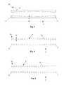
- FIGS. 1 through 3are side perspective views of various variations of the expandable support device.
- FIGS. 4 through 6illustrate various variations of cross-section A-A of the expandable support device.
- FIG. 7 through 10are side perspective views of various variations of the expandable support device.
- FIG. 11is a side perspective view of a variation of the expandable support device in a contracted configuration.
- FIGS. 12 through 14illustrate a variation of a method of deploying multiple expandable support devices.
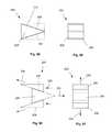
- FIG. 15is a schematic figure of a variation of the expandable support device in a contracted configuration.
- FIG. 16is a schematic figure of a variation of the expandable support device of FIG. 15 in an expanded configuration.
- FIG. 17is a perspective view of a variation of the expandable support device.
- FIG. 18is a side view of the variation of the expandable support device of FIG. 17 .
- FIG. 19is a top view of the variation of the expandable support device of FIG. 17 .
- FIG. 20is a front view of the variation of the expandable support device of FIG. 17 .
- FIG. 21is a perspective view of a variation of the expandable support device.
- FIG. 22is a side view of the variation of the expandable support device of FIG. 21 .
- FIG. 23is a front view of the variation of the expandable support device of FIG. 21 .
- FIG. 24is a perspective view of a variation of the expandable support device.
- FIG. 25is a front view of the variation of the expandable support device of FIG. 24 .
- FIG. 26illustrates a flattened pattern for a variation of the expandable support device.
- FIG. 27is a perspective view of a variation of the expandable support device.
- FIG. 28is a front view of the variation of the expandable support device of FIG. 27 .
- FIG. 29is a perspective view of a variation of the expandable support device.
- FIG. 30is a front view of the variation of the expandable support device of FIG. 29 .
- FIG. 31is a perspective view of a variation of the expandable support device.
- FIG. 32is top view of the variation of the expandable support device of FIG. 31 .
- FIG. 33is a side view of the variation of the expandable support device of FIG. 31 .
- FIG. 34is a front view of the variation of the expandable support device of FIG. 31 .
- FIG. 35illustrates a variation of section A-A of the variation of the expandable support device of FIG. 31 .
- FIG. 36illustrates a variation of section B-B of the variation of the expandable support device of FIG. 31 .
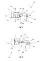
- FIG. 37is a side perspective view of a variation of the expandable support device.
- FIG. 38is a front view of the variation of the expandable support device of FIG. 37 .
- FIG. 39is a rear perspective view of the variation of the expandable support device of FIG. 37 .
- FIG. 40is a bottom view of the variation of the expandable support device of FIG. 37 .
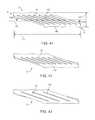
- FIG. 41is a side view of the variation of the expandable support device of FIG. 37 .
- FIGS. 42 and 43are side views of various variations of the expandable support device.
- FIG. 44is a side perspective view of a variation of the expandable support device.
- FIGS. 45 through 47are front views of various variations of the expandable support devices.
- FIG. 48is a top perspective view of a variation of the expandable support device.
- FIG. 49is top view of the variation of the expandable support device of FIG. 48 .
- FIG. 50is a front view of the variation of the expandable support device of FIG. 48 .
- FIGS. 51 and 52illustrate a variation of a method for using a delivery system for the expandable support element.
- FIGS. 53 through 55illustrate a variation of a method for accessing a damage site in the vertebra.
- FIG. 56illustrates two methods for delivering expandable support devices to the vertebral column.
- FIGS. 57 through 62illustrate various methods for deploying the expandable support device into the damage site in the vertebra.
- FIGS. 63 and 64illustrate a variation of a method for deploying one or more expandable support devices into one or more damage sites in the vertebra.
- FIG. 65illustrates a variation of a method for deploying the expandable support device into the damage site in the vertebra.
- FIG. 66illustrates a variation of a method for deploying the expandable support device into the damage site in the vertebra.
- FIG. 67illustrates variations of methods for deploying the expandable support device into the damage site in the vertebra.
- FIGS. 68 and 69illustrate a variation of a method for deploying the expandable support device into the damage site in the vertebra.
- FIGS. 70 and 71illustrate a variation of a method for deploying a locking pin into the expandable support device in the damage site in the vertebra.
- FIGS. 72 through 77illustrate a variation of a method for deploying a locking pin into the expandable support device.
- FIG. 78illustrates a variation of the slidable expansion device.
- FIG. 79illustrates a variation of a method for loading the expandable support device of FIG. 10 onto the slidable expansion device of FIG. 78 .
- FIGS. 80 and 81illustrate a variation of a method for using the slidable expansion device.
- FIG. 82illustrates a variation of a method for using the slidable expansion device.
- FIG. 83illustrates a variation of a method for using the slidable expansion device.
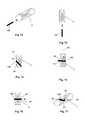
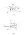
- FIGS. 84 and 85show side and front views, respectively, of a variation of the expansion component.
- FIGS. 86 and 87show side and front views, respectively, of a variation of a method for using the variation of the expansion component of FIGS. 84 and 85 .
- FIGS. 88 and 89show side and front views, respectively, of a variation of the expansion component.
- FIGS. 90 and 91show side and front views, respectively, of a variation of a method for using the variation of the expansion component of FIGS. 88 and 89 .
- FIGS. 92 and 93show side and front views, respectively, of a variation of the expansion component.
- FIGS. 94 and 95show side and front views, respectively, of a variation of a method for using the variation of the expansion component of FIGS. 92 and 93 .
- FIGS. 96 and 97show side and front views, respectively, of a variation of the expansion component.
- FIGS. 98 and 99show side and front views, respectively, of a variation of a method for using the variation of the expansion component of FIGS. 96 and 97 .
- FIGS. 100 and 101show side and front views, respectively, of a variation of the expansion component.
- FIGS. 102 and 103show side and front views, respectively, of a variation of a method for using the variation of the expansion component of FIGS. 100 and 101 .
- FIGS. 104 and 105illustrate a variation of the expansion component and a variation of a method for using the expansion component.
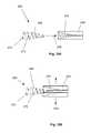
- FIGS. 106 and 107illustrate a variation of a deployment tool.
- FIGS. 108 through 110illustrate a variation of a method of expanding the expandable support device using the deployment tool of FIGS. 106 and 107 .
- FIGS. 111 and 112are schematic illustrations of the forces acting on the expandable support device as illustrated in FIGS. 108-110 .
- FIGS. 113 and 114illustrate a variation of the expandable support device in an expanded configuration.
- FIGS. 115 and 116illustrate a variation of a method for deploying the expandable support device into the damage site in the vertebra.
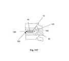
- FIG. 117illustrates a variation of a method for deploying a second expandable support device or locking pin in the damage site in the vertebra.
- FIGS. 118 through 120illustrate a method for deploying a second expandable support device in the vertebra.
- FIG. 121is a close-up view of a variation of section A-A of FIG. 120 .
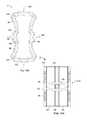
- FIG. 122illustrates a variation of a buttress.
- FIGS. 123 through 125illustrate variations of section B-B of the buttress of FIG. 122 .
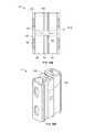
- FIGS. 126 through 128illustrate a variation of a method for deploying a buttress.
- FIG. 129illustrates a variation of a method for deploying a buttress.
- FIGS. 130 through 132illustrate a variation of a method for deploying a buttress
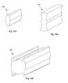
- FIG. 133illustrates a variation of a buttress.
- FIG. 134illustrates a variation of section C-C of the buttress of FIG. 133 .
- FIG. 135illustrates a variation of a method for deploying a buttress.
- FIGS. 136 through 139illustrate a method for deploying the expandable support device of FIGS. 17 through 20 .
- FIGS. 140 through 142illustrate a method for deploying the expandable support device of FIGS. 31 through 34 .
- FIG. 143illustrates the deployed expandable support device of FIGS. 31 through 34 in use.
- FIGS. 144 and 145illustrate a method for deploying the expandable support device of FIGS. 35 and 36 .
- FIG. 146illustrates a method of using the expandable support device of FIGS. 31 through 34 with the band.
- FIG. 147 through 149illustrate variations of a locking pin.
- FIG. 1illustrates an expandable support device 2 , such as a stent, that can be implanted in a bone, such as a compression fracture in a vertebra, in the intervertebral space between two vertebrae, or in soft tissue, such as a herniated intervertebral disc.
- the expandable support device 2should be biocompatible.
- the expandable support device 2can have one of many configurations, and can be used, for example, for methods of repairing vertebral bone fractures or supporting adjacent vertebral bodies for fusion.
- the expandable support device 2can have a first end 4 and a second end 6 .
- FIG. 2illustrates that the expandable support device 2 can have a wall 8 .
- the wall 8can have struts 10 .
- the struts 10can vary in density along the length of the expandable support device 2 from the first end 4 to the second end 6 .
- the density of the struts 10can be higher near the first end 4 than near the second end 6 (as shown).
- the density of the struts 10can be higher near the second end 6 than near the first end 4 .
- the density of the struts 10can be higher near the first end 4 and the second end 6 than the middle between the first 4 and second ends 6 . Controlling the density, thickness and arrangement of the struts results in controlled deployment and shape of the implant.
- FIG. 3illustrates that the expandable support device 2 can have a tapered configuration before or after deployment.
- the first end 4can have a first diameter 12 .
- the second end 6can have a second diameter 14 .
- the second diameter 14can be greater than the first diameter 12 (as shown).
- the first diameter 12can be greater than the second diameter 14 .
- the first diameter 12 and second diameters 14can both be greater than a diameter in the middle of the expandable support device 2 between the first end 4 and second end 6 .
- the tapered configurationcan be a result of a greater strength of the expandable support device 2 at or near the tapered section or end of the expandable support device 2 .
- a greater density of struts 10can be at the first end 4 to achieve this result.
- the struts 10 at the first end 4can have a greater strut diameter than the struts 10 at the second end 6 .
- the expandable support device 2can have a first port 16 at the first end 4 .
- the expandable support device 2can have a second port 18 at the second end 6 .
- FIG. 4illustrates that the device in cross-section A-A can have a varying wall thickness 20 along a longitudinal length of the expandable support device 2 from the first end 4 to the second end 6 .
- the wall thickness 20can be greater at the first 4 and second ends 6 than in the middle of the expandable support device 2 between the first 4 and second ends 6 .
- FIG. 5illustrates that the wall 8 can be made from struts 10 .
- the strut diameters 22can vary along the length of the expandable support device 2 .
- FIG. 5illustrates the strut diameters 22 can be greater at the first 4 and second ends 6 than the strut diameters 22 between the first 4 and second ends 6 .
- FIG. 6illustrates that the strut diameters 22 can be greater at the second end 6 than the strut diameters 22 at the first end 4 .
- the strength of the wall 8can be adjusted along the length of the expandable support device 2 by designing varying, for example, strut diameters 22 , strut cross-sectional areas, strut densities (i.e., strut spacing, number of struts), strut cross-sectional geometries, and combinations thereof.
- FIG. 7illustrates that the expandable support device 2 can have a bullet shape.
- the wall 8can have a first radius of curvature 24 near or at the first end 4 .
- the first end 4can have a first rim 26 circumferentially around the first end 4 .
- the wall 8can have a second radius of curvature 28 near or at the second end 6 .
- the first radius of curvature 24can be less than the second radius of curvature 28 (as shown).
- the first radius of curvature 24can be greater than the second radius of curvature 28 .
- the first and second radii of curvaturecan be greater than a radius of curvature between the first 4 and second ends 6 .
- FIG. 8illustrates that the expandable support device 2 can be sharply pointed at the first end 4 (as shown), and/or second end 6 .
- the first end 4can have a smaller first port 16 than the second port 18 , or no first port 16 (as shown).
- the first end 4can be made from, for example, a plastic and/or dense mesh of thick wires.
- FIG. 9illustrates that the expandable support device 2 can have a thread 34 .
- the expandable support device 2can be rotated during implantation to screw into an implant site, such as a vertebra.
- FIG. 10illustrates an expandable support device 2 that can have an engagement groove 36 .
- the engagement groove 36can be on the inner diameter of the expandable support device 2 .
- the engagement groove 36can be configured to engage the external engagement thread on the expansion component.
- FIG. 11illustrates a twistable coil variation of the expandable support device 2 in an untwisted configuration.
- the untwisted expandable support device 2can have a contracted diameter 38 .
- the contracted diameter 38can be less than the expanded diameter of the twistable coil variation of the expandable support device 2 .
- the coilscan be resiliently or deformably altered in configuration during untwisting. The coils can resiliently expand when released from the untwisted configuration.
- FIG. 12illustrates that multiple expandable support devices 2 can each have an outer diameter and an inner diameter in a relaxed configuration.
- the first expandable support device 40can have a first device outer diameter 42 that can be equal to or greater, for example by a substantially small amount, than a second device inner diameter 44 .
- the second expandable support device 46can have a second device outer diameter 48 that can be equal to or greater, for example by a substantially small amount, than a third device inner diameter 50 .
- the first device 40can have a first device inner diameter 52 and the third device 54 can have a third device outer diameter 56 .
- the third expandable support device 54can be deployed.
- the second expandable support device 46can then be inserted 58 into the third expandable support device 54 .
- the second expandable support device 46can then be expanded 60 in the third expandable support device 54 .
- the first expandable support device 40can then be inserted 62 into the second expandable support device 46 .
- the first expandable support device 40can then be expanded 64 into the second expandable support device 46 .
- the concentrically smaller expandable support devices 2can butt against the next larger expandable support devices 2 (the gap shown in FIG. 14 between the third and second expandable support devices 54 and 46 , respectively, is for illustrative purposes).
- each expandable support device 2can support, and/or substantially lock into place, the next larger, abutting, expandable support device 2 .
- FIGS. 15 and 16illustrate an expandable support device 2 that can have a first wedge 66 and a second wedge 68 , such as the buttress of FIGS. 133 through 135 , supra, of which any characteristic, feature, or functionality can be used for the expandable support device 2 described herein.
- a first wedge force 70can be applied to the first wedge 66 .
- a second wedge force 72can be applied to the second wedge 68 .
- the first wedge 66can translate in the direction of arrow 74 , as shown.
- the second wedge 68can translate in the direction of arrow 76 , as shown.
- FIG. 16illustrates that the expandable support device 2 can have a larger, expanded diameter 78 after the first 70 and second wedge forces 72 have been applied.
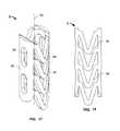
- FIGS. 17 through 20illustrate a variation of a biocompatible implant that can be used for tissue repair, for example for repair bone fractures such as spinal compression fractures, and/or repairing soft tissue damage, such as herniated vertebral discs and/or an intervertebral/interspinous spacer or fusion device.
- the implantcan be an expandable support device 2 , for example a stent.
- the expandable support device 2can have a longitudinal axis 80 .
- the expandable support device 2can have an elongated wall 8 around the longitudinal axis 80 .
- the expandable support device 2can have a substantially and/or completely hollow longitudinal port 82 along the longitudinal axis 80 .
- the wall 8can have one or more first struts 84 .
- the first struts 84can be configured to be deformable and/or expandable.
- the wall 8can have can have one or more second struts 86 .
- the second struts 86can be substantially undeformable and substantially inflexible.
- the first struts 84can be flexibly (e.g., deformably rotatably) attached to the second struts 86 .
- the wall 8can be configured to expand radially away from the longitudinal axis 80 , for example in two opposite radial directions.
- a first set of first struts 84can be aligned parallel to each other with respect to the longitudinal axis 80 .
- a second set of first struts 80can be aligned parallel to each other with respect to the longitudinal axis 80 .
- the second set of first struts 84can be on the opposite side of the longitudinal axis 80 from the first set of first struts 84 .
- the second struts 86can attach any or all sets of first struts 84 to other sets of first struts 84 .
- the second struts 86can have one or more ingrowth ports 88 .
- the ingrowth ports 88can be configured to encourage biological tissue ingrowth therethrough during use in order to aid in fixing the expandable support device in place and/or promote fusion of adjacent bone structures, either within the same bone (e.g., for vertebroplasty or kyphoplasty) or between adjacent bone structures (e.g., between adjacent vertebral bodies to promote fusion).
- the ingrowth ports 88can be configured to releasably and/or fixedly attach to a deployment tool or other tool.
- the ingrowth ports 88can be configured to increase, and/or decrease, and/or focus pressure against the surrounding biological tissue during use.
- the ingrowth ports 88can be configured to increase and/or decrease the stiffness of the second struts 86 .
- the ingrowth ports 88can be configured to receive and/or attach to a buttress.
- the first struts 84can be configured to have a “V” shape.
- the space between adjacent first struts 84can be configured to receive and/or attach to a locking pin during use.
- the wall 8can have a wall thickness 20 .
- the wall thickness 20can be from about 0.25 mm (0.098 in.) to about 5 mm (0.2 in.), for example about 1 mm (0.04 in.).
- the wall 8can have an inner diameter 90 .
- the inner diameter 90can be from about 1 mm (0.04 in.) to about 30 mm (1.2 in.), for example about 6 mm (0.2 in.).
- the wall thickness 20 and/or the inner diameter 90can vary with respect to the length along the longitudinal axis 80 .
- the wall thickness 20 and/or the inner diameter 90can vary with respect to the angle formed with a plane parallel to the longitudinal axis 80 .
- the expandable support devicemay have an expansion ratio (i.e., the ratio of the unexpanded diameter to the expanded diameter) of from about 1:2 to about 1:5 or greater, depending upon the application.
- an expansion ratioi.e., the ratio of the unexpanded diameter to the expanded diameter
- the expansion ratiois preferably about 1:3 to about 1:4.
- FIGS. 21 through 23illustrate another variation of an expandable support device 2 that can be configured to expand away from the longitudinal axis 80 in more than two opposite directions, for example in two sets of opposite radial directions.
- the wall 8can have four sets of first struts 84 .
- Each set of first struts 84can be opposite to another set of first struts 84 .
- Each of four sets of second struts 86can attach each set of first struts 84 .
- Providing four orthogonally oriented sets of first struts 10permits expansion in two orthogonal planes, which advantageously may be considered height and width directions.
- an intervertebral implantfor example, such expansion in two directions permits height expansion to engage and support adjacent vertebral bodies and width expansion to increase the width of the surface contact area or “footprint” of engagement between the implant and the adjacent vertebrae.
- the implantmay be filled with bone growth promoting substances (e.g., autologous bone, allograft bone, bone extenders, bone growth factors, bone morphogenic proteins, stem cells, carriers for any of them, and mixtures of any of them or with other suitable substances) to promote bone growth into and through the space.
- bone growth promoting substancese.g., autologous bone, allograft bone, bone extenders, bone growth factors, bone morphogenic proteins, stem cells, carriers for any of them, and mixtures of any of them or with other suitable substances
- the first struts 84 on a first longitudinal half of the expandable support device 2can be oriented (e.g., the direction of the pointed end of the “V” shape) in the opposite direction as the first struts 84 on a second longitudinal half of the expandable support device 2 . See FIGS. 21-22 . Orienting the first struts 84 in opposite directions permits controlled expansion of the expandable support device 2 such that the overall length of the expandable support device 2 can be conserved during and after expansion, with minimal longitudinal displacement of radially opposed sides of the expandable support device 2 .
- FIGS. 24 and 25illustrate that the longitudinal port 82 can have one or more lock grooves 92 .
- the lock grooves 92can be configured to receive and/or slidably and fixedly or releasably attach to a locking pin or buttress.
- the locking pin or buttressmay be an insertable structure separate from the expandable support device 2 or may be preassembled to the expandable support device 2 or may be integrally formed with the expandable support device 2 .
- FIG. 26illustrates a visually flattened pattern of the wall 8 for another variation of the expandable support device 2 .
- the pattern of the wall 8can be flattened for illustrative purposes only, or the wall 8 can be cut in a flattened state and welded or otherwise secured into a three dimensional shape during the manufacturing process.
- the patterncan have multiple configurations for the first and/or second struts 84 and/or 86 .
- first struts 84can have a first configuration 84 a (e.g., a “V” shape in oppositely oriented sets) and first struts 84 can have a second configuration 84 b (e.g., a “U” shape in oppositely oriented sets.
- second struts 12are relatively narrow between the sets of first struts).
- FIGS. 27 and 28illustrate that that rather than the generally circular or oval cross sectional shape of prior variations, the expandable support device 2 can have a square or, rectangular cross-sectional configuration. As shown, the square or rectangular configuration can include features such as grooves 20 to receive one or more locking pins or buttresses, as contemplated herein.
- FIGS. 29 and 30illustrate that the expandable support device 2 can have protruding tissue engagement elements, such as tissue hooks, and/or barbs, and/or cleats 94 (referred to herein as cleats 94 ).
- the cleats 94can be integral with and/or fixedly or removably attached to the first and/or second struts 86 .
- the cleats 94can be on substantially opposite sides of the expandable support device 2 .
- tissue engagement elementswill engage adjacent tissue, e.g., adjacent vertebral bodies in the case of an intervertebral spacer, to help secure the device in place relative to adjacent structures.
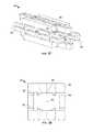
- FIGS. 31 through 34illustrate that the expandable support device 2 can have panels attached to other panels at flexible joints.
- the expandable support device 2can have first panels 96 attached to and/or integral with second panels 98 at first joints 100 .
- the second panels 98can be attached to and/or integral with third panels 102 at second joints 104 .
- the expandable support device 2can have one or more tool engagement ports 106 , for example on the first panels 96 .
- the expandable support device 2can have one or more ingrowth ports 88 , for example, on the third panels 102 .
- the outside of the first panel 96can be concave.
- FIGS. 35 and 36illustrate that the expandable support device 2 can have first and/or second struts 84 , 86 and/or and panels 96 , 98 .
- the first and/or second struts 84 , 86can be internal to the panels 96 , 98 .
- the first struts 84can be attached to the third panels 102 .
- the expandable support device 2can have a radius of curvature along the longitudinal axis 80 .
- the radius of curvaturecan be from about 1 mm (0.04 in.) to about 250 mm (10 in.), for example about 50 mm (2 in.).
- the wall 8is shown sans panels or struts for illustrative purposes.
- the expandable support device 2can have at least one flat side, for example two flat sides. The two flat sides can be on opposite sides of the expandable support device 2 from each other.
- the internal first strut 84can help provide controlled expansion of the device and internal support to the expanded device.
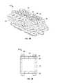
- FIGS. 37 through 41illustrate an expandable support device 2 , that can be implanted in a bone, such as a compression fracture in a vertebra, or in soft tissue, such as a herniated intervertebral disc, or interspinous ligament.
- the expandable support device 2should be biocompatible.
- the expandable support device 2can be used for tissue repair, for example for repair bone fractures such as spinal compression fractures, and/or repairing soft tissue damage, such as herniated vertebral discs of fusion or fixation.
- the expandable support device 2can have a longitudinal axis 80 .
- the expandable support device 2can have a first end 4 and a second end 6 .
- the first end 4can be substantially parallel with the second end 6 .
- the first end 4may be displaced from the longitudinal axis 80 by a first angle 108 and the second end may be displaced from the longitudinal axis 80 by a second angle 110 when the expandable support device 2 is in a contracted configuration (as shown).
- the expandable support device 2can be hollow, for example along the longitudinal axis 80 .
- the first end 4can have a first port 16 .
- the second end 6can have a second port 18 .
- the first angle 108can be substantially equal to the second angle 110 .
- the angles 108 , 110can be from about 0° to about 90°, more narrowly from about 5° to about 45°, yet more narrowly from about 10° to about 30°, for example about 20°.
- the expandable support device 2can have a wall 8 .
- the outer and/or inner surfaces of the wall 8can be configured to increase friction or be capable of an interference fit with another object, such as a second expandable support device 46 .
- the configurations to increase friction or be capable of an interference fitinclude teeth, knurling, coating, or combinations thereof.
- the wall 8can have struts 10 .
- the wall 8can have about 8 struts 10 on each side of the expandable support device 2 .
- the struts 10can be substantially parallel to the slanted configuration of the angled first end 4 and/or second end 6 .
- the struts 10can be separated from the other struts 10 by wall openings 112 .
- the expandable support device 2can have about 7 wall openings 112 on each side.
- the wall openings 112can be substantially parallel to the first end 4 and/or second end 6 , for example when the expandable support device 2 is in a contracted configuration.
- the expandable support device 2can have ingrowth ports 88 .
- the expandable support device 2can have a first port 16 and/or a second port 18 .
- a hollow of the expandable support device 2can be completely or partially coated and/or filled with agents and/or a matrix as listed below.
- the leading end of the expandable support device 2can be sharpened.
- the leading endcan be used to help move tissue aside during implantation and deployment.
- the leading endcan be self-penetrating.
- the expandable support device 2When in a contracted configuration, the expandable support device 2 can have a contracted length 114 (i.e., the length when the expandable support device is in a radially contracted configuration) and a contracted height 116 .
- the contracted length 114can be from about 0.318 cm (0.125 in.) to about 10 cm (4 in.), for example about 3.8 cm (1.5 in).
- the contracted height 116can be from about 0.1 cm (0.05 in.) to about 3 cm (1 in.), for example about 0.8 cm (0.3 in.).
- FIG. 42illustrates that the expandable support device 2 can have shorter struts 10 than the struts shown in FIGS. 37 through 41 .
- the length of the struts 10can be from about 0.3 cm (0.1 in.) to about 5 cm (2 in.), for example about 2 cm (0.7 in.), also for example about 1 cm (0.5 in.).
- FIG. 43illustrates that the expandable support device 2 can have from relatively few struts 10 . It is contemplated that the expandable support device 2 may have from about 2 struts to about 50 struts 10 . About 4 struts 10 to about 8 struts 10 may be suitable for many applications.
- the expandable support device 2can have from about 1 wall opening 112 to about 51 wall openings 112 , for example about 3 wall openings 112 , also for example about 7 wall openings 112 .
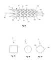
- FIG. 44illustrates that the expandable support device 2 can have a first pane 118 , a second pane 120 , a third pane 122 , and a fourth pane 124 .
- a first joint 100can attach the first pane 118 to the second pane 120 .
- a second joint 104can attach the second pane 120 to the third pane 122 .
- a third joint 126can attach the third pane 122 to the fourth pane 124 .
- the jointscan rotatably attach the panes.
- the jointscan be separate from or integral with the panes.
- Each panecan have struts 10 and wall openings 112 . During use, the joints can enable the panes to rotate in-plane, as shown by arrows 128 .
- FIGS. 45 , 46 and 47illustrate that the expandable support device 2 , can have for example a square or rectangular, circular, or polygonal cross-section, respectively.
- FIG. 47shows the joints as contemplated above in the description of FIG. 44 as nodes having a wider section than the wall 8 , but the joints can also have the same width or a smaller width than the wall 8 .
- FIGS. 48 through 50illustrate that the expandable support device 2 can have a radius of curvature 130 along the longitudinal axis 80 .
- the radius of curvature 130can be from about 1 mm (0.04 in.) to about 250 mm (10 in.), for example about 50 mm (2 in.).
- the wall 8is shown without panels or struts 10 for illustrative purposes, but it will be understood that the initial configuration and deployment force and method can influence the shape of the deployed implant.
- the expandable support device 2can have at least one flat side, for example two flat sides. The two flat sides can be on opposite sides of the expandable support device 2 from each other.
- the expandable support devices 2can have textured and/or porous surfaces for example, to increase friction against bone surfaces, and/or promote tissue ingrowth.
- the expandable support devices 2can be coated with a bone growth factor, such as a calcium base.
- the expandable support device 2can be covered by a thin metal screen.
- the thin metal screencan expand and/or open when the expandable support device 2 expands.
- any or all elements of the expandable support device 2 and/or other devices or apparatuses described hereincan be made from, for example, a single or multiple stainless steel alloys, nickel titanium alloys (e.g., Nitinol), cobalt-chrome alloys (e.g., ELGILOY® from Elgin Specialty Metals, Elgin, Ill.; CONICHROME® from Carpenter Metals Corp., Wyomissing, Pa.), nickel-cobalt alloys (e.g., MP35N® from Magellan Industrial Trading Company, Inc., Westport, Conn.), molybdenum alloys (e.g., molybdenum TZM alloy, for example as disclosed in International Pub. No.
- WO 03/082363 A2published 9 Oct. 2003, which is herein incorporated by reference in its entirety
- tungsten-rhenium alloysfor example, as disclosed in International Pub. No. WO 03/082363
- polymerssuch as polyethylene teraphathalate (PET)/polyester (e.g., DACRON® from E. I.
- PGApolyglycolic acid
- PLApolylactic
- any or all elements of the expandable support device 2 and/or other devices or apparatuses described hereincan be, have, and/or be completely or partially coated with agents and/or a matrix a matrix for cell ingrowth or used with a fabric, for example a covering (not shown) that acts as a matrix for cell ingrowth.
- the matrix and/or fabriccan be, for example, polyester (e.g., DACRON® from E. I. Du Pont de Nemours and Company, Wilmington, Del.), polypropylene, PTFE, ePTFE, nylon, extruded collagen, silicone or combinations thereof.
- the expandable support device 2 and/or elements of the expandable support device 2 and/or other devices or apparatuses described herein and/or the fabriccan be filled, coated, layered and/or otherwise made with and/or from cements, fillers, glues, and/or an agent delivery matrix known to one having ordinary skill in the art and/or a therapeutic and/or diagnostic agent. Any of these cements and/or fillers and/or glues can be osteogenic and osteoinductive growth factors.
- cements and/or fillersexamples include bone chips, demineralized bone matrix (DBM), calcium sulfate, coralline hydroxyapatite, biocoral, tricalcium phosphate, calcium phosphate, polymethyl methacrylate (PMMA), biodegradable ceramics, bioactive glasses, hyaluronic acid, lactoferrin, bone morphogenic proteins (BMPs) such as recombinant human bone morphogenetic proteins (rhBMPs), other materials described herein, or combinations thereof.
- DBMdemineralized bone matrix
- PMMApolymethyl methacrylate
- BMPsbone morphogenic proteins
- rhBMPsrecombinant human bone morphogenetic proteins
- the agents within these matricescan include any agent disclosed herein or combinations thereof, including radioactive materials; radiopaque materials; cytogenic agents; cytotoxic agents; cytostatic agents; thrombogenic agents, for example polyurethane, cellulose acetate polymer mixed with bismuth trioxide, and ethylene vinyl alcohol; lubricious, hydrophilic materials; phosphor cholerae; anti-inflammatory agents, for example non-steroidal anti-inflammatories (NSAIDs) such as cyclooxygenase-1 (COX-1) inhibitors (e.g., acetylsalicylic acid, for example ASPIRIN® from Bayer AG, Leverkusen, Germany; ibuprofen, for example ADVIL® from Wyeth, Collegeville, Pa.; indomethacin; mefenamic acid), COX-2 inhibitors (e.g., VIOXX® from Merck & Co., Inc., Whitehouse Station, N.J.; CELEBREX®
- the expandable support devices 2can be laser cut, machined, cut by wire electrical discharge machining (“EDM”) or made by other suitable techniques.
- EDMelectrical discharge machining
- the expandable support device 2can be cut in a fully contracted or unexpanded configuration or may be cut in a partially opened pattern, then loaded (e.g., crimped) onto a deployment tool 132 (e.g., balloon 134 ).
- the loaded expandable support device 2can have a smaller profile while plastically deforming the struts 10 past their limits.
- the expandable support device 2can be longitudinally segmented. Multiple expandable support devices 2 can be attached first end 4 to second end 6 , and/or a single expandable support device 2 can be severed longitudinally into multiple expandable support devices 2 .
- FIG. 51illustrates that the expandable support device 2 can be loaded in a collapsed (i.e., contracted) configuration onto a deployment tool 132 .
- the deployment tool 132can have an expandable balloon 134 catheter 136 as known to those having an ordinary level of skill in the art.
- the catheter 136can have a fluid conduit 138 .
- the fluid conduit 138can be in fluid communication with balloon 134 .
- the balloon 134 and the deployment tool 132can be the balloon 134 and deployment tool 132 described in PCT Application No. US2005/033,965, Publication No. WO 2006/034,396, filed 21 Sep.
- the balloon 134can be configured to receive a fluid pressure of at least about 5,000 kPa (50 atm), more narrowly at least about 10,000 kPa (100 atm), for example at least about 14,000 kPa (140 atm).
- the deployment tool 132can be a pair of wedges, an expandable jack, other expansion tools, or combinations thereof.
- FIG. 52illustrates that the fluid pressure in the fluid conduit 138 and balloon 134 can increase, thereby inflating the balloon 134 , as shown by arrows.
- the expandable support device 2can expand, for example, due to pressure from the balloon 134 .
- FIGS. 53 (side view) and 54 (top view)illustrate a vertebral column 140 that can have one or more vertebra 142 separated from the other vertebra 142 by discs 144 .
- the vertebra 142can have a damage site 146 , for example a compression fracture.
- An access tool 148can be used to gain access to the damage site 146 and or increase the size of the damage site 146 to allow deployment of the expandable support device 2 .
- the access tool 148can be a rotating or vibrating drill 150 that can have a handle 152 .
- the drill 150may oscillate, as shown by arrows 154 .
- the drill 150can then be translated, as shown by arrow 156 , toward and into the vertebra 142 so as to pass into the damage site 146 .
- FIG. 55illustrates that the access tool 148 can be translated, as shown by arrow 158 , to remove tissue at the damage site 146 .
- the access tool 148can create an access port 160 at the surface of the vertebra 142 .
- the access port 160can open to the damage site 146 .
- the access tool 148can then be removed from the vertebra 142 .
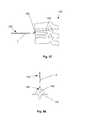
- FIG. 56illustrates that a first deployment tool 162 can enter posteriorly through the subject's back.
- the first deployment tool 162can enter through a first incision 164 in the skin 166 on the posterior side 167 of the subject near the vertebral column 140 .
- the first deployment tool 162can be translated, as shown by arrow 168 , to position a first expandable support device 40 into a first damage site 170 .
- the first access port 172can be on the posterior side 167 of the vertebra 142 .
- a second deployment tool 174can enter through a second incision 176 (as shown) in the skin 166 .
- the second incision 176may be posterior (as shown) or may be anterior, lateral, posterior lateral, or the like.
- the second deployment tool 174can be translated through muscle (not shown), around nerves 178 , the spinal cord 180 , and anterior 182 of the vertebral column 140 .
- the second deployment tool 174can be steerable.
- the second deployment tool 174can be steered, as shown by arrow 184 , to align the distal tip of the second expandable support device 46 with a second access port 186 on a second damage site 188 .
- the second access port 186can face anteriorly 182 .
- the second deployment tool 174can translate, as shown by arrow 190 , to position the second expandable support device 46 in the second damage site 188 .
- the vertebra 142can have multiple damage sites and expandable support devices deployed therein.
- the expandable support devicescan be deployed from the anterior 182 , posterior 167 , both lateral, superior, inferior, any angle, or combinations of the directions thereof.
- a single devicemay be deployed from one direction rather than multiple devices from multiple directions.
- FIGS. 57 and 58illustrate translating, as shown by arrow, the deployment tool 132 loaded with the expandable support device 2 through the access port 160 from the anterior side 182 of the vertebral column 140 .
- FIGS. 59 and 60illustrate that the deployment tool 132 can be deployed from the posterior side 167 of the vertebral column 140 .
- the deployment tool 132can be deployed off-center, for example, when approaching the posterior side 167 of the vertebral column 140 .
- FIG. 61illustrates that deployment tool 132 can position the expandable support device 2 in the vertebra 142 and into the damage site 146 .
- FIG. 62illustrates that the fluid pressure in the fluid conduit 136 and the balloon 134 can increase, thereby inflating the balloon 134 , as shown by arrows.
- the expandable support device 2can expand, for example, due to pressure from the balloon 134 .
- the balloon 134can be expanded until the expandable support device 2 is substantially fixed to the vertebra 142 .
- the balloon 134 and/or the expandable support device 2can reshape the vertebral column 140 to a more natural configuration during expansion of the device.
- FIGS. 63 and 64illustrate that first and second deployment tools 162 and 174 can position and deploy first and second expandable support devices 40 and 46 simultaneously, and/or in the same vertebra 142 and into the same or different damage sites 170 and 188 .
- FIG. 65illustrates that the fluid pressure in the fluid conduit 138 and the balloon 134 can increase, thereby inflating the balloon 134 , as shown by arrows.
- the expandable support device 2can expand, for example, due to pressure from the balloon 134 .
- the balloon 134can be expanded until the expandable support device 2 is substantially fixed to the vertebra 142 .
- the balloon 134 and/or the expandable support device 2can reshape the vertebral column 140 to a more natural configuration during expansion of the balloon 134 .
- FIG. 66illustrates that the access port 160 can be made close to the disc 144 , for example when the damage site 146 is close to the disc 144 .
- the deployment tool 132can be inserted through the access port 160 and the expandable support device 2 can be deployed as described supra.
- FIG. 67a front view of the vertebral column 140 , illustrates that more than one expandable support device 2 can be deployed into a single vertebra 142 .
- a first expandable support device(not shown) can be inserted through a first access port 172 and deployed in a first damage site 170
- a second expandable support device(not shown) can be inserted through a first access port 172 and deployed in a second damage site 188 .
- the first access port 172can be substantially centered with respect to the first damage site 170 .
- the first expandable support device(not shown) can expand, as shown by arrows 64 , substantially equidirectionally, aligned with the center of the first access port 172 .
- the second access port 186can be substantially not centered with respect to the second damage site 188 .
- the second expandable support device(not shown) can substantially anchor to a side of the damage site 146 and/or the surface of the disc 144 , and then expand, as shown by arrows 60 , substantially directionally away from the disc 144 .
- FIG. 68illustrates that the fluid pressure can be released from the balloon 134 , and the balloon 134 can return to a pre-deployment configuration, leaving the expandable support element substantially fixed to the vertebra 142 at the damage site 146 .
- the access port 160can have an access port diameter 192 .
- the access port diameter 192can be from about 1.5 mm (0.060 in.) to about 40 mm (2 in.), for example about 8 mm (0.3 in.).
- the access port diameter 192can be a result of the size of the access tool 148 and in the unexpanded expandable support device 2 .
- the damage site 146can have a deployed diameter 194 .
- the deployed diameter 194can be from about 1.5 mm (0.060 in.) to about 120 mm (4.7 in.), for example from about 10 mm (0.4 in.) to about 20 mm (0.8 in.), or from about 12 mm (0.47 in.) to about 16 mm (0.63 in.).
- the deployed diameter 194can be greater than, equal to, or less than the access port diameter 192 .
- FIG. 69illustrates that the deployment tool 132 can be removed, as shown, from the vertebra 142 after the expandable support device 2 is deployed.
- FIGS. 70 and 71illustrate that a locking pin 196 can be inserted, as shown by arrow, into the deployed expandable support device 2 , for example, after the expandable support device 2 is deployed in the vertebra 142 .
- the locking pin 196can prevent the expandable support device 2 from collapsing after the expandable support device 2 is deployed in the vertebra 142 .
- the locking pin 196can form an interference fit with the expandable support device 2 or may include features to hold the locking pin in place.
- the locking pin 196can be parallel with the longitudinal axis 80 , as shown in FIG. 72 , for example when the locking pin 196 is slidably received by and/or attached to the lock grooves 92 (see for example, FIG. 25 ).
- the locking pin 196can be perpendicular to the longitudinal axis 80 , as shown in FIG. 71 , for example when the locking pin 196 is slidably received by and/or attached to ports formed between adjacent first struts 84 after the expandable support device 2 is expanded.
- FIGS. 72 through 77illustrate various methods for deploying the locking pin 196 into the expandable support device 2 .
- the locking pin 196can be translated, as shown by arrow, into the expandable support device 2 along the implant longitudinal axis.
- a first end of the locking pin 196can be translated, as shown by arrow, at an oblique angle, into a first port 16 formed between adjacent first struts 84 .
- a second end of the locking pin 196can be rotated, as shown by arrow.
- FIG. 77shows the locking pin 196 deployed into, and forming an interference fit with, the expandable support device 2 .
- FIG. 78illustrates a slidable expansion device 198 .
- the slidable expansion device 198can have an expansion component 200 , a deployment extension 202 , a handle 204 , or combinations thereof.
- the expansion component 200can be configured to radially and/or longitudinally expand.
- the expansion component 200can expand directly against tissue and/or expand an implant pre-loaded into the deployment site, and/or loaded onto or into the expansion component 200 .
- the expansion component 200can have a first slidable element 206 and a second slidable element 208 .
- the first and second slidable elements 206 and 208can be configured to slide relative to each other.
- An interface 210can be provided between the first slidable element 206 and the second slidable element 208 .
- the expansion component 200optionally can have an engagement element, such as an external engagement rib or thread 212 .
- the external engagement thread 212can spiral around the expansion component 200 .
- the interface 210can intersect the external engagement thread 212 .
- the deployment extension 202can have a first extension arm 214 and a second extension arm 216 .
- the first extension arm 214can be fixedly attached to a third fixed element, such as the handle 204 .
- the first extension arm 214can be fixedly attached to the expansion component 200 .
- the first extension arm 214can maintain a substantially constant distance between the handle 204 and the first slidable element 206 .
- the second extension arm 216can be fixedly attached to the slidable expansion device 198 and slidably attached to the third fixed element, such as the handle 204 .
- the angle between an extension arm longitudinal axis 218 , such as an axis extending along the second extension arm 216 , and the interface 210can form an expansion angle 220 .
- the expansion angle 220can be from about 0° to about 85°, more narrowly from about 10° to about 45°, for example about 30°.
- the handle 204can have an activation system configured to expand the expansion component 200 .
- the handle 204can have a lever 222 than can be fixedly or rotatably attached to the second extension arm 216 .
- the lever 222can be rotatably attached to a lever pivot 224 .
- the lever pivot 224can be fixedly attached to a case of the handle 204 .
- a return spring 226can be attached to the lever 222 .
- the return spring 226can apply a force against the lever 222 sufficient to keep the lever 222 against a first stop 228 when the slidable expansion device 198 is not in use.
- FIG. 79illustrates that the expandable support device 2 can be loaded onto the expansion component 200 of the slidable expansion device 198 .
- the expandable support device 2can be translated, as shown by arrow 230 , to the expansion component 200 .
- the optional engagement groove 36can be aligned with and engage the optimal external engagement rib or thread 212 , such as by rotating the expandable support device 2 , to engage thread and load the expandable support device 2 onto the expansion component 200 .
- FIG. 80illustrates that, when loaded on the slidable expansion device 198 , the expandable support device 2 (shown in see-through without details) can have an expandable support device diameter 234 .
- FIG. 81illustrates that the lever 222 can be forced to retractably rotate, as shown by arrow 236 , the second extension arm 216 .
- the movement of the lever 222can compress the return spring 226 .
- the rotation of the lever 222can be limited by physical interference at the second stop 238 .
- the translation of the second extension arm 216can, in turn, translate, as shown by arrow 240 the second slidable element 208 .
- the second slidable element 208can shift downward (with respect to the page) and the first slidable element 206 can shift upward, thereby causing expansion, as shown by arrows 242 , of the expansion component 200 and the expandable support device 2 .
- the expandable support device diameter 234can be larger after expansion than before expansion.
- the first extension arm 214 and/or the second extension arm 216can resiliently and/or deformably flex during expansion of the expansion component 200 .
- FIG. 82illustrates that the first and/or second slidable element 206 and/or 208 can have no external engagement thread 212 .
- the first and/or second slidable element 206 and/or 208can be coated or lubricated with a low-friction material, such as TEFLON® (i.e., PTFE) from E. I. Du Pont de Nemours and Company, Wilmington, Del.
- TEFLON®i.e., PTFE
- FIG. 83illustrates that the force can be removed from the lever 222 .
- the return spring 226can translate, as shown by arrow 244 .
- the lever 222can be rotated, as shown by arrow 246 , by the return spring 226 .
- the first stop 228can limit the rotation of the lever 222 .
- the second extension arm 216can translate, as shown by arrow 248 , the second slidable element 208 .
- the expansion component 200can return to a contracted configuration.
- the expansion component 200can be removed from the then-expanded expandable support device 2 . While the deployment device of FIGS. 78-83 , for example, shows a pistol type grip with a compressible handle, it also is contemplated that the device could be actuated by a rotational motion about the longitudinal axis of the deployment component.
- FIGS. 84 and 85illustrate that the expansion component 200 can have a substantially triangular, or wedge-shaped first and second slidable elements 206 and 208 .
- wedge shaped elements 96 and 98may be incorporated into the expandable device. Translation of wedges within the device can assist in the deployment of the expandable device and may provide reinforcement for the deployed device.
- the various wedge, locking pin or buttress configurations disclosed hereincould aid in deployment and provide rigid support for the expandable device.
- wedge configurations as shown in FIGS. 84-99which may include interlocking directional teeth or a tongue and groove interface as described with regard to the buttress of FIGS.
- 133-135may be included as part of the expandable device. These features can provide expansion force to the device and added support and rigidity to the device in addition to struts 10 , 12 .
- the combined effect of the wedges with the strutsprovides the desirable combination of controlled expansion of the device with balanced counterforces within the device (the wedges opposing the struts and vice versa) so that the device may be deployed to the desired location and degree of expansion, the counterforce of the interlocking wedges and the struts establishing a uniform structure not prone to release or collapse.
- FIGS. 86 and 87illustrate that a first slidable element force, shown by arrow 250 , can be applied to the first slidable element 206 in substantially the opposite direction as a second slidable element force, shown by arrow 252 , can be applied to the second slidable element 208 .
- the first slidable element 206 and the second slidable element 208can translate, as shown by arrows 254 and 248 , in opposite directions with respect to each other parallel to the interface 210 to cause expansion.
- FIGS. 88 and 89illustrate that the expansion component 200 can have substantially triangular or wedge-shaped first and second slidable elements 206 and 208 .
- the expansion component 200can have multiple first slidable elements 206 and multiple interfaces 210 .
- FIGS. 90 and 91illustrate that a first slidable element force, shown by arrow 250 , can be applied to the first slidable elements 206 in substantially the opposite direction as a second slidable element force, shown by arrow 252 , can be applied to the second slidable element 208 .
- the first slidable elements 206 and the second slidable element 208can translate, as shown by arrows 254 and 248 .
- FIGS. 92 and 93illustrate that the expansion component 200 can have a first slidable element 206 that can be flexibly resilient or deformably and can have a conical port therein.
- the second slidable element 208can be substantially conical and can be positioned in the conical port of the first slidable element 206 .
- FIGS. 94 and 95illustrate that a first slidable element force, shown by arrow 250 , can be applied to the first slidable element 206 in substantially the opposite direction as a second slidable element force, shown by arrow 252 can be applied to the second slidable element 208 .
- the first slidable element 206can translate, as shown by arrows 254 .
- the first slidable element 206can resiliently or deformably expand radially outward.
- FIGS. 96 and 97illustrate that the expansion component 200 can have multiple first slidable elements 206 that can be flexibly resilient or deformably and can have a conical port therein.
- the first slidable elements 206can be segmented or separated by element separations 148 .
- the element separations 256can be thinned and very low resistant or completely severed areas or lines (as shown).
- the second slidable element 208can be substantially conical and can be positioned in the conical port of the first slidable element 206 .
- FIGS. 98 and 99illustrate that first slidable element forces, shown by arrow 250 , can be applied to the first slidable elements 206 in substantially the opposite direction as a second slidable element force, shown by arrow 252 , can be applied to the second slidable element 208 .
- the first slidable elements 206can translate, as shown by arrows 254 .
- the first slidable elements 206can resiliently or deformably expand radially outward.
- the first slidable elements 206can be attached by a filament or thin strip of material (not shown), or can be distinct and unattached to each other.
- FIGS. 100 and 101illustrate that the expansion component 200 can have a first slidable element 206 that can be rotatably attached to a second slidable element 208 via a hinge 150 .
- the hinge 258can rotate about a hinge pin 260 that can pass through the first slidable element 206 and the second slidable element 208 .
- the second slidable element 208can have a cam 262 .
- a camshaft 264can rotatably attach the cam 262 to the second slidable element 208 .
- the cam 262can be attached to all or part of the deployment extension 202 .
- the cam 262can be located in a depression or cavity in the second slidable element 208 .
- FIGS. 102 and 103illustrate that the deployment extension 202 can be translated, as shown by arrow 266 .
- This translationcan rotate, as shown by arrow 268 , the cam 262 .
- the cam 262can slide along the first slidable element 206 and can cause the first slidable element 206 to rotate, as shown by arrow 254 , about the hinge pin 260 .
- FIG. 104illustrates that the first slidable element 206 can have a slidable element port 270 .
- the slidable element port 270can be shaped (e.g., grooved or threaded) to receive the second slidable element 208 .
- the second slidable element 208can be conical.
- the second slidable element 208can have a slidable element thread 272 .
- the slidable element port 270can be threaded.
- the second slidable element 208can be translated, as shown by arrow 248 and rotated, as shown by arrow 274 , as the second slidable element 208 approaches the slidable element port 270 .
- FIG. 105illustrates that the second slidable element 208 can enter the slidable element port 270 .
- the first slidable element 206can expand, as shown by arrows 276 , as the slidable element port 270 receives the second slidable element 208 .
- the slidable element thread 272can engage the slidable element port 270 .
- the second slidable element 208can be rotated, as shown by arrows 274 , as the second slidable element 208 enters the first slidable element 206 .
- FIG. 106illustrates an alternative deployment tool 132 can having a shaft 278 and a sleeve 280 .
- the shaft 278can be slidably received, as shown by arrow, by the sleeve 280 .
- the shaft 278can have a first catch 282 .
- the shaft 278can have a relief 284 section or an additional catch on a side opposite the first catch 282 .
- the sleeve 280can have a second catch 286 .
- FIG. 107illustrates that the deployment tool 132 can have an actuator 288 , such as an ergonomic lever handle 152 .
- the handle 152can be attached to the sleeve 280 .
- the actuator 288can be attached to the shaft 278 . Applying a force to the actuator 288 can cause the shaft 278 to slide or translate in the sleeve 280 .
- FIG. 108illustrates that the expandable support device 2 , for example in a contracted configuration, can be loaded on the shaft 278 .
- the first end 4 of the expandable support device 2can be received by and/or interference fit in the first catch 282 .
- the second end 6 of the expandable support device 2can be received by and/or interference fit in the relief 284 .
- the first and/or second end 6 of the expandable support device 2can be beveled. The beveled ends can be shaped to fit the first catch 282 and/or relief 284 .
- FIG. 109illustrates that the shaft 278 can slide, as shown by arrow, relative to the sleeve 282 .
- the second end 6 of the expandable support device 2can be received by and/or engage the second catch 286 .
- the second end 6can interference fit the second catch 286 .
- FIG. 110illustrates that the shaft 278 can be forcibly slid into the sleeve 282 by squeezing the lever handle (see FIG. 107 ).
- the expandable support device 2can be squeezed between the first catch 282 and the second catch 286 .
- the expandable support device 2can be resiliently and/or deformably forced into an expanded configuration.
- the expandable support device 2can be released from the deployment tool 132 , for example, by releasing the shaft 278 from the handle and sliding the shaft 278 distally through the sleeve 282 .
- FIG. 111illustrates that the expandable support device 2 can be expanded by applying force, as shown by arrows, on the first end 4 and the second end 6 , and by directing the force toward the expandable support device 2 .
- FIG. 112illustrates that the expandable support device 2 can be expanded by applying force, as shown by arrows, radially outward against the wall 8 .
- FIGS. 113 and 114illustrate various variations of the expandable support device 2 in an expanded configuration.
- the wall openings 112can expand when the expandable support device 2 is in an expanded configuration.
- the expandable support device 2can have an expanded height 290 and an expanded length 292 .
- the expanded height 290can be from about 0.3 cm (0.1 in.) to about 5 cm (2 in.), for example about 2 cm (0.6 in.).
- the expanded length 292can be from about 0.1 cm (0.05 in) to about 3.8 cm (1.5 in.), for example about 3 cm (1 in.).
- the expandable support device 2can have first 294 and second 296 expanded intersection angles.
- the first expanded intersecting angle 294can be substantially equal to the second expanded intersecting angle 296 .
- the expanded intersecting anglescan be from about 45° to about 135°, for example about 110°, also for example about 90°.
- FIG. 115illustrates that the fluid pressure can be released from the balloon 134 , and the balloon 134 can return to a pre-deployment configuration, leaving the expandable support element substantially fixed to the vertebra 142 at the damage site 146 .
- the access port 160can have an access port diameter 192 .
- the access port diameter 192can be from about 1.5 mm (0.060 in.) to about 40 mm (2 in.), for example about 8 mm (0.3 in.).
- the access port diameter 192can be a result of the size of the access tool 148 .
- the damage site 146can have a deployed diameter 194 .
- the deployed diameter 194can be from about 1.5 mm (0.060 in.) to about 120 mm (4.7 in.), for example about 20 mm (0.8 in.).
- the deployed diameter 194can be greater than, equal to, or less than the access port diameter 192 .
- FIG. 116illustrates that the deployment tool 132 can be removed, as shown by arrow, from the vertebra 142 after the expandable support device 2 is deployed.
- FIG. 117illustrate that a second expandable support device 46 and/or locking pin 196 can be inserted, as shown by arrow 298 , into the first deployed expandable support device 2 , for example, after the first expandable support device 40 is deployed in the vertebra 142 .
- the second expandable support device 46 and/or locking pin 196can prevent the first expandable support device 40 from collapsing after the first expandable support device 40 is deployed in the vertebra 142 .
- the second expandable support device 46 and/or locking pin 196can form an interference fit with the expandable support device 2 .
- FIG. 118illustrates that the second expandable support device 46 can be translated, as shown by arrow, into the first expandable support device 40 .
- the first expandable support device 40can be in an expanded, contracted, or other configuration.
- the second expandable support device 46can be in an expanded, contracted, or other configuration.
- the struts 10 and/or wall openings 112 of the first expandable support device 40can be angled in a substantially opposite direction to the struts 10 and/or wall openings 112 of the second expandable support device 46 .
- FIG. 119illustrates that after the second expandable support device 46 is inside the first expandable support device 40 , the second expandable support device 46 can be subject to any or all of the expansion forces, as shown by arrows.
- FIG. 120illustrates that the second expandable support device 46 can be in an expanded configuration in the first expandable support device 40 .
- the second expandable support device 46can be translated into the first expandable support device 40 and expanded, as shown in FIGS. 118 and 119 .
- the second expandable support device 46can be in an expanded configuration and screwed or otherwise attached into the first expandable support device 40 .
- FIG. 121illustrates that the first expandable support device 40 can be rotatably attached to, or have an interference fit with, the second expandable support device 46 .
- the first expandable support device 40can have first teeth 300 , for example on the inside surface of the wall 8 .
- the second expandable support device 46can have second teeth 302 , for example on the outside surface of the wall 8 .
- the first teeth 300can engage the second teeth 302 .
- FIG. 122illustrates a buttress 304 .
- the buttress 304can have a longitudinal axis 80 .
- the buttress 304can have a tensioner 306 .
- a first end 4 of the tensioner 306can be fixedly or removably attached a first end 4 of the buttress 304 .
- a second end 6 of the tensioner 306can be fixedly or removably attached a second end 6 of the buttress 304 .
- the tensioner 306can be in a relaxed configuration when the buttress 304 is in a relaxed configuration.
- the tensioner 306can create a tensile force between the first end 4 of the buttress 304 and the second end 6 of the buttress 304 when the buttress 1304 is in a stressed configuration.
- the tensioner 306can be, for example, a resilient wire, a coil, spring, an elastic member, or combinations thereof.
- the buttress 304can have a coil 308 .
- the coil 308can have turns 310 of a wire, ribbon, or other coiled element.
- FIGS. 123 through 125illustrate that the coil 310 can be made from a wire, ribbon, or other coiled element having a circular, square, or oval cross-section, respectively.
- the buttress 304can be a series of connected hoops.
- FIG. 126illustrates that the buttress 304 can be loaded into a hollow deployment tool 132 in a smear (i.e., partially shear stressed) configuration at a smear section 310 .
- the buttress 304 in the smear section 310can have a relaxed first end 4 , a stressed smear section 310 , and a relaxed second end 6 .
- the longitudinal axis 80can be not straight (i.e., non-linear) through the smear section 310 .
- FIG. 127illustrates that part of the buttress 304 can be forced, as shown by arrow, out of the deployment tool 132 .
- the second end 6can exit the deployment tool 132 before the remainder of the buttress 304 .
- the smear section 310can then partially relax.
- the second end 6can be positioned to a final location before the remainder of the buttress 304 is deployed from the deployment tool 132 .
- FIG. 128illustrates that the remainder of the buttress 304 can be forced, as shown by arrow, out of the deployment tool 132 .
- the smear section 310can substantially relax.
- the longitudinal axis 80can return to a substantially relaxed and/or straight (i.e., linear) configuration.
- FIG. 129illustrates that the buttress 304 can be deployed 312 in the expandable support device 2 , for example with the longitudinal axis 80 of the buttress 304 or the strongest orientation of the buttress 304 aligned substantially parallel with the primary load bearing direction (e.g., along the axis of the spine) of the expandable support device 2 .
- FIG. 130illustrates that the buttress 304 can be loaded into the hollow deployment tool 132 with the longitudinal axis 80 of the buttress 1304 substantially parallel with the hollow length of the deployment tool 132 .
- the entire length of the buttress 304can be under shear stress.
- FIG. 131illustrates that part of the buttress 304 can be forced, as shown by arrow, out of the deployment tool 132 .
- the second end 6 of the buttress 304can exit the deployment tool 132 before the remainder of the buttress 304 .
- the tensioner 306can apply a tensile stress between the ends of the buttress 304 , for example, forcing the deployed second end 6 of the buttress 304 to “stand up straight”.
- the second end 6 of the buttress 304can be positioned to a final location before the remainder of the buttress 304 is deployed from the deployment tool 132 .
- FIG. 132illustrates that the remainder of the buttress 304 can be forced, as shown by arrow, out of the deployment tool 132 .
- the buttress 304can substantially relax.
- FIG. 133illustrates that the buttress 304 can have a first wedge 66 and a second wedge 68 .
- the first wedge 66can contact the second wedge 68 at a directionally locking interface 314 .
- the directionally locking interface 314can have directional teeth 316 .
- FIG. 134illustrates that the first wedge 66 can be slidably attached to the second wedge 68 .
- the first wedge 66can have a tongue 318 .
- the second wedge 68can have a groove 320 .
- the tongue 318can be slidably attached to the groove 320 .
- a gap 322can be between the tongue 318 and the groove 320 .
- the gap 322can be wider than the height of the teeth 316 .
- the gap 322can be configured to allow the first wedge 66 to be sufficiently distanced from the second wedge 68 so the teeth 316 on the first wedge 66 can be disengaged from the teeth 316 on the second wedge 68 .
- the buttress 304 in a compact configurationcan be placed inside of a fully or partially deployed expandable support device 2 .
- FIG. 135illustrates that the first wedge 66 can then be translated, as shown by arrows, relative to the second wedge 68 along the directionally locking interface 314 .
- the first wedge 66can abut a first side of the inside of the deployed expandable support device 2 .
- the second wedge 68can abut a second side of the inside of the deployed expandable support device 2 .
- the directionally interference fitting teeth 316can prevent disengagement of the buttress 304 .
- a stop 324can limit the relative translation of the first wedge 66 and the second wedge 68 .
- FIGS. 136 through 139illustrate another form of expandable support device 2 of FIGS. 17 through 20 that can be in a deployed configuration.
- the first struts 84can be expanded, as shown by arrows 326 .
- the expandable support device 2can be passively narrow, as shown by arrows 330 .
- the expandable support device 2can be deployed in a configuration where the second struts 86 can be placed against the load bearing surfaces of the deployment site.
- the expandable support device 2can have a minimum inner diameter 330 and a maximum inner diameter 332 .
- the minimum inner diameter 330can be less than the pre-deployed inner diameter.
- the minimum inner diameter 330can be from about 0.2 mm (0.01 in.) to about 120 mm (4.7 in.), for example about 2 mm (0.08 in.).
- the diameters 330 and/or 332can also be from about 1.5 mm (0.060 in.) to about 40 mm (2 in.), for example about 8 mm (0.3 in.).
- the maximum inner diameter 332can be more than the pre-deployed inner diameter.
- the maximum inner diameter 332can be from about 1.5 mm (0.060 in.) to about 120 mm (4.7 in.), for example about 18 mm (0.71 in.).
- FIGS. 140 through 142illustrate the expandable support device 2 of FIGS. 31 through 34 that can be in a deployed configuration.
- a tool(not shown) can releasably attach to the tool engagement port 106 .
- the toolcan be used to position the expandable support device 2 .
- the toolcan be used to expand the expandable support device 2 , for example, by forcing the first panels 96 toward each other.
- the second joints 104can form angles less than about 90°.
- a compressive forceas shown by arrows 334 , causes additional inward deflection, as shown by arrows 336 , of the first panels 96 , and will not substantially compress the expandable support device 2 .
- FIG. 144illustrates a deployed configuration of the expandable support device 2 of FIGS. 35 and 36 .
- the first struts 84can expand to the size of the expandable support device 2 .
- FIG. 145illustrates that the first struts 84 can touch each other, for example if the expandable support device 2 is sufficiently expanded. In the case of extreme compressive loads applied to the expandable support device 2 , the first struts 84 can buckle into each other, thereby providing additional resistance to compressive loads.
- FIG. 146illustrates the expandable support device 2 that can have one or more bands 130 .
- the bands 338can be attached to other bands 338 and/or attached to the expandable support device 2 with band connectors 340 .
- the bands 338can be attached to the expandable support device 2 before, during, or after deployment.
- the bands 338can increase the compressive strength of the expandable support device 2 .
- FIG. 147illustrates a locking pin 196 configured and dimensioned to fit into the longitudinal port 82 , for example, of the expanded expandable support device 2 of FIGS. 136 through 139 .
- FIG. 148illustrates the locking pin 196 configured and dimensioned to fit into the longitudinal port 82 , for example, of the expanded expandable support device 2 of FIGS. 140 through 143 .
- FIG. 149illustrates a locking pin 196 configured and dimensioned to fit into the longitudinal port 82 , for example, of the expanded expandable support device 2 of FIGS. 24 and 25 and/or FIGS. 27 and 28 .
- the longitudinal port 82 and the remaining void volume in the damage site 146can be filled with, for example, biocompatible coils, bone cement, morselized bone, osteogenic powder, beads of bone, polymerizing fluid, paste, a matrix (e.g., containing an osteogenic agent and/or an anti-inflammatory agent, and/or any other agent disclosed supra), Orthofix, cyanoacrylate, or combinations thereof.
- the expandable support device 2can be implanted in the place of all or part of a vertebral disc 144 .
- the expandable support device 2can be implanted into the hernia in the disc 144 annulus, and/or the expandable support device 2 can be implanted into the disc 144 nucleus.
- PCT Application No. PCT/US2005/033965, Publication No. WO 2006/034396, entitled “Balloon and Methods of Making and Using”, filed Sep. 21, 2005, and U.S. Provisional Patent Application Ser. No. 60/611,972, filed on Sep. 21, 2004,are herein incorporated by reference in their entireties.
- PCT Application No. PCT/US2005/034728, Publication No. WO 2006/068,682entitled “Expandable Support Device and Method of Use”, filed Sep. 26, 2005, and U.S. Provisional Patent Application No. 60/612,728, filed on Sep. 24, 2004, are herein incorporated by reference in their entireties.
Landscapes
- Health & Medical Sciences (AREA)
- Engineering & Computer Science (AREA)
- Biomedical Technology (AREA)
- Orthopedic Medicine & Surgery (AREA)
- Neurology (AREA)
- Life Sciences & Earth Sciences (AREA)
- Transplantation (AREA)
- General Health & Medical Sciences (AREA)
- Veterinary Medicine (AREA)
- Heart & Thoracic Surgery (AREA)
- Public Health (AREA)
- Animal Behavior & Ethology (AREA)
- Cardiology (AREA)
- Vascular Medicine (AREA)
- Oral & Maxillofacial Surgery (AREA)
- Surgery (AREA)
- Physical Education & Sports Medicine (AREA)
- Nuclear Medicine, Radiotherapy & Molecular Imaging (AREA)
- Medical Informatics (AREA)
- Molecular Biology (AREA)
- Prostheses (AREA)
Abstract
Description
Claims (8)
Priority Applications (1)
| Application Number | Priority Date | Filing Date | Title |
|---|---|---|---|
| US14/085,563US9259329B2 (en) | 2004-09-21 | 2013-11-20 | Expandable support device and method of use |
Applications Claiming Priority (9)
| Application Number | Priority Date | Filing Date | Title |
|---|---|---|---|
| US61200104P | 2004-09-21 | 2004-09-21 | |
| US61272304P | 2004-09-24 | 2004-09-24 | |
| US61272404P | 2004-09-24 | 2004-09-24 | |
| US61781004P | 2004-10-12 | 2004-10-12 | |
| PCT/US2005/034115WO2006034436A2 (en) | 2004-09-21 | 2005-09-21 | Expandable support device and method of use |
| PCT/US2005/034742WO2006037013A1 (en) | 2004-09-24 | 2005-09-26 | Expandable support devices and methods of use |
| PCT/US2005/037126WO2006042334A2 (en) | 2004-10-12 | 2005-10-12 | Expandable support device and method of use |
| US11/689,471US8709042B2 (en) | 2004-09-21 | 2007-03-21 | Expandable support device and method of use |
| US14/085,563US9259329B2 (en) | 2004-09-21 | 2013-11-20 | Expandable support device and method of use |
Related Parent Applications (1)
| Application Number | Title | Priority Date | Filing Date |
|---|---|---|---|
| US11/689,471ContinuationUS8709042B2 (en) | 2004-09-21 | 2007-03-21 | Expandable support device and method of use |
Publications (2)
| Publication Number | Publication Date |
|---|---|
| US20140088713A1 US20140088713A1 (en) | 2014-03-27 |
| US9259329B2true US9259329B2 (en) | 2016-02-16 |
Family
ID=36090695
Family Applications (5)
| Application Number | Title | Priority Date | Filing Date |
|---|---|---|---|
| US11/689,465Active2027-05-04US9314349B2 (en) | 2004-09-21 | 2007-03-21 | Expandable support device and method of use |
| US11/689,471Active2028-02-02US8709042B2 (en) | 2004-09-21 | 2007-03-21 | Expandable support device and method of use |
| US14/085,563Expired - LifetimeUS9259329B2 (en) | 2004-09-21 | 2013-11-20 | Expandable support device and method of use |
| US14/933,820AbandonedUS20160058572A1 (en) | 2004-09-21 | 2015-11-05 | Expandable support device and method of use |
| US15/658,173Expired - LifetimeUS11051954B2 (en) | 2004-09-21 | 2017-07-24 | Expandable support device and method of use |
Family Applications Before (2)
| Application Number | Title | Priority Date | Filing Date |
|---|---|---|---|
| US11/689,465Active2027-05-04US9314349B2 (en) | 2004-09-21 | 2007-03-21 | Expandable support device and method of use |
| US11/689,471Active2028-02-02US8709042B2 (en) | 2004-09-21 | 2007-03-21 | Expandable support device and method of use |
Family Applications After (2)
| Application Number | Title | Priority Date | Filing Date |
|---|---|---|---|
| US14/933,820AbandonedUS20160058572A1 (en) | 2004-09-21 | 2015-11-05 | Expandable support device and method of use |
| US15/658,173Expired - LifetimeUS11051954B2 (en) | 2004-09-21 | 2017-07-24 | Expandable support device and method of use |
Country Status (2)
| Country | Link |
|---|---|
| US (5) | US9314349B2 (en) |
| WO (1) | WO2006034436A2 (en) |
Cited By (6)
| Publication number | Priority date | Publication date | Assignee | Title |
|---|---|---|---|---|
| USD816844S1 (en) | 2017-06-29 | 2018-05-01 | American Medical Ortho Systems LLC | Lumbar interbody implant |
| USD841167S1 (en) | 2017-08-16 | 2019-02-19 | American Medical Ortho Systems LLC | Lumbar interbody implant |
| US10285820B2 (en) | 2008-11-12 | 2019-05-14 | Stout Medical Group, L.P. | Fixation device and method |
| US10758289B2 (en) | 2006-05-01 | 2020-09-01 | Stout Medical Group, L.P. | Expandable support device and method of use |
| US10940014B2 (en) | 2008-11-12 | 2021-03-09 | Stout Medical Group, L.P. | Fixation device and method |
| US11051954B2 (en) | 2004-09-21 | 2021-07-06 | Stout Medical Group, L.P. | Expandable support device and method of use |
Families Citing this family (203)
| Publication number | Priority date | Publication date | Assignee | Title |
|---|---|---|---|---|
| DE60139262D1 (en) | 2000-08-28 | 2009-08-27 | Disc Dynamics Inc | SYSTEM FOR RECONSTRUCTING JOINT SURFACES OF MAMMALS |
| DE10154163A1 (en)* | 2001-11-03 | 2003-05-22 | Advanced Med Tech | Device for straightening and stabilizing the spine |
| US6793678B2 (en) | 2002-06-27 | 2004-09-21 | Depuy Acromed, Inc. | Prosthetic intervertebral motion disc having dampening |
| AU2004212942A1 (en) | 2003-02-14 | 2004-09-02 | Depuy Spine, Inc. | In-situ formed intervertebral fusion device |
| US20040267367A1 (en) | 2003-06-30 | 2004-12-30 | Depuy Acromed, Inc | Intervertebral implant with conformable endplate |
| AU2003273871A1 (en)* | 2003-09-13 | 2005-04-21 | Aesculap Ag And Co. Kg | Method and device for determining the angle between the femur and the tibia |
| US8636802B2 (en) | 2004-03-06 | 2014-01-28 | DePuy Synthes Products, LLC | Dynamized interspinal implant |
| US7465318B2 (en)* | 2004-04-15 | 2008-12-16 | Soteira, Inc. | Cement-directing orthopedic implants |
| DE602005023605D1 (en)* | 2004-05-21 | 2010-10-28 | Myers Surgical Solutions Llc | FRACTURE FIXATION AND STITIZATION STABILIZATION SYSTEM |
| US20070156241A1 (en) | 2004-08-09 | 2007-07-05 | Reiley Mark A | Systems and methods for the fixation or fusion of bone |
| US20180228621A1 (en) | 2004-08-09 | 2018-08-16 | Mark A. Reiley | Apparatus, systems, and methods for the fixation or fusion of bone |
| US9949843B2 (en) | 2004-08-09 | 2018-04-24 | Si-Bone Inc. | Apparatus, systems, and methods for the fixation or fusion of bone |
| US20060036251A1 (en) | 2004-08-09 | 2006-02-16 | Reiley Mark A | Systems and methods for the fixation or fusion of bone |
| US8388667B2 (en) | 2004-08-09 | 2013-03-05 | Si-Bone, Inc. | Systems and methods for the fixation or fusion of bone using compressive implants |
| US9662158B2 (en) | 2004-08-09 | 2017-05-30 | Si-Bone Inc. | Systems and methods for the fixation or fusion of bone at or near a sacroiliac joint |
| US9452001B2 (en)* | 2005-02-22 | 2016-09-27 | Tecres S.P.A. | Disposable device for treatment of infections of human limbs |
| US7267690B2 (en) | 2005-03-09 | 2007-09-11 | Vertebral Technologies, Inc. | Interlocked modular disc nucleus prosthesis |
| US7955339B2 (en) | 2005-05-24 | 2011-06-07 | Kyphon Sarl | Low-compliance expandable medical device |
| EP1903949A2 (en) | 2005-07-14 | 2008-04-02 | Stout Medical Group, L.P. | Expandable support device and method of use |
| US8366773B2 (en) | 2005-08-16 | 2013-02-05 | Benvenue Medical, Inc. | Apparatus and method for treating bone |
| WO2008103781A2 (en) | 2007-02-21 | 2008-08-28 | Benvenue Medical, Inc. | Devices for treating the spine |
| AU2006279558B2 (en) | 2005-08-16 | 2012-05-17 | Izi Medical Products, Llc | Spinal tissue distraction devices |
| US20070067034A1 (en)* | 2005-08-31 | 2007-03-22 | Chirico Paul E | Implantable devices and methods for treating micro-architecture deterioration of bone tissue |
| US8998923B2 (en) | 2005-08-31 | 2015-04-07 | Spinealign Medical, Inc. | Threaded bone filling material plunger |
| US20070088436A1 (en)* | 2005-09-29 | 2007-04-19 | Matthew Parsons | Methods and devices for stenting or tamping a fractured vertebral body |
| US9737414B2 (en) | 2006-11-21 | 2017-08-22 | Vertebral Technologies, Inc. | Methods and apparatus for minimally invasive modular interbody fusion devices |
| WO2008070863A2 (en) | 2006-12-07 | 2008-06-12 | Interventional Spine, Inc. | Intervertebral implant |
| WO2008076330A1 (en) | 2006-12-15 | 2008-06-26 | Soteira, Inc. | Drills and methods for vertebrostenting |
| EP2124778B1 (en) | 2007-02-21 | 2019-09-25 | Benvenue Medical, Inc. | Devices for treating the spine |
| CA2682298C (en)* | 2007-02-23 | 2015-04-28 | Zimmer Gmbh | Implant for fracture treatment |
| JP5631597B2 (en) | 2007-03-12 | 2014-11-26 | スタウト メディカル グループ,エル.ピー. | Expandable mounting device and method |
| US8273124B2 (en) | 2007-05-17 | 2012-09-25 | Depuy Spine, Inc. | Self-distracting cage |
| US8900307B2 (en) | 2007-06-26 | 2014-12-02 | DePuy Synthes Products, LLC | Highly lordosed fusion cage |
| EP2205162B1 (en) | 2007-11-02 | 2015-09-09 | Stout Medical Group LP | Expandable attachment device |
| US9101491B2 (en)* | 2007-12-28 | 2015-08-11 | Nuvasive, Inc. | Spinal surgical implant and related methods |
| US7799056B2 (en) | 2007-12-31 | 2010-09-21 | Warsaw Orthopedic, Inc. | Bone fusion device and methods |
| US7985231B2 (en)* | 2007-12-31 | 2011-07-26 | Kyphon Sarl | Bone fusion device and methods |
| CA2781407A1 (en) | 2008-01-14 | 2009-07-23 | Michael P. Brenzel | Apparatus and methods for fracture repair |
| EP2237748B1 (en) | 2008-01-17 | 2012-09-05 | Synthes GmbH | An expandable intervertebral implant |
| EP2249720A1 (en)* | 2008-01-22 | 2010-11-17 | Stout Medical Group LP | Expandable orthopedic device and method |
| US8267939B2 (en) | 2008-02-28 | 2012-09-18 | Stryker Spine | Tool for implanting expandable intervertebral implant |
| US8795365B2 (en)* | 2008-03-24 | 2014-08-05 | Warsaw Orthopedic, Inc | Expandable devices for emplacement in body parts and methods associated therewith |
| US8936641B2 (en) | 2008-04-05 | 2015-01-20 | DePuy Synthes Products, LLC | Expandable intervertebral implant |
| WO2009155319A1 (en) | 2008-06-17 | 2009-12-23 | Soteira, Inc. | Devices and methods for fracture reduction |
| EP2303196B1 (en) | 2008-07-23 | 2018-10-24 | Marc I. Malberg | Modular nucleus pulposus prosthesis |
| US9364338B2 (en) | 2008-07-23 | 2016-06-14 | Resspond Spinal Systems | Modular nucleus pulposus prosthesis |
| US8246627B2 (en)* | 2008-08-07 | 2012-08-21 | Stryker Corporation | Cement delivery device for introducing cement into tissue, the device having a cavity creator |
| US10045860B2 (en) | 2008-12-19 | 2018-08-14 | Amicus Design Group, Llc | Interbody vertebral prosthetic device with self-deploying screws |
| US8523944B2 (en) | 2008-12-31 | 2013-09-03 | Spinex Tec, Llc | Methods and apparatus for vertebral body distraction and fusion employing flexure members |
| US8535327B2 (en) | 2009-03-17 | 2013-09-17 | Benvenue Medical, Inc. | Delivery apparatus for use with implantable medical devices |
| US8147528B2 (en)* | 2009-03-18 | 2012-04-03 | Depuy Spine, Inc. | Laminoplasty methods and devices |
| US8435265B2 (en) | 2009-03-18 | 2013-05-07 | Depuy Spine, Inc. | Laminoplasty methods using hinge device |
| US8628577B1 (en) | 2009-03-19 | 2014-01-14 | Ex Technology, Llc | Stable device for intervertebral distraction and fusion |
| WO2010111246A1 (en) | 2009-03-23 | 2010-09-30 | Soteira, Inc. | Devices and methods for vertebrostenting |
| US9526620B2 (en) | 2009-03-30 | 2016-12-27 | DePuy Synthes Products, Inc. | Zero profile spinal fusion cage |
| US8784451B2 (en)* | 2009-06-04 | 2014-07-22 | Linares Medical Devices, Llc | Elevating insert for cervical spinal vertebrae |
| KR20120047231A (en) | 2009-06-17 | 2012-05-11 | 트리니티 올쏘피딕스, 엘엘씨 | Expanding intervertebral device and methods of use |
| KR101687435B1 (en) | 2009-07-06 | 2016-12-19 | 신세스 게엠바하 | Expandable fixation assemblies |
| WO2011011626A2 (en)* | 2009-07-22 | 2011-01-27 | Spinex Tec, Llc | Coaxial screw gear sleeve mechanism |
| US9615933B2 (en)* | 2009-09-15 | 2017-04-11 | DePuy Synthes Products, Inc. | Expandable ring intervertebral fusion device |
| US9393129B2 (en) | 2009-12-10 | 2016-07-19 | DePuy Synthes Products, Inc. | Bellows-like expandable interbody fusion cage |
| US8636746B2 (en) | 2009-12-31 | 2014-01-28 | Spinex Tec, Llc | Methods and apparatus for insertion of vertebral body distraction and fusion devices |
| US20110178520A1 (en) | 2010-01-15 | 2011-07-21 | Kyle Taylor | Rotary-rigid orthopaedic rod |
| WO2011091052A1 (en) | 2010-01-20 | 2011-07-28 | Kyle Taylor | Apparatus and methods for bone access and cavity preparation |
| US9220554B2 (en) | 2010-02-18 | 2015-12-29 | Globus Medical, Inc. | Methods and apparatus for treating vertebral fractures |
| WO2011112615A1 (en) | 2010-03-08 | 2011-09-15 | Krinke Todd A | Apparatus and methods for securing a bone implant |
| EP2547292B1 (en) | 2010-03-16 | 2019-04-24 | Pinnacle Spine Group, LLC | Ntervertebral implants and graft delivery systems |
| US20110257748A1 (en)* | 2010-04-15 | 2011-10-20 | Jung-Tung Liu | Artificial spinal implant |
| US8535380B2 (en) | 2010-05-13 | 2013-09-17 | Stout Medical Group, L.P. | Fixation device and method |
| US8979860B2 (en) | 2010-06-24 | 2015-03-17 | DePuy Synthes Products. LLC | Enhanced cage insertion device |
| US9907560B2 (en) | 2010-06-24 | 2018-03-06 | DePuy Synthes Products, Inc. | Flexible vertebral body shavers |
| US8623091B2 (en) | 2010-06-29 | 2014-01-07 | DePuy Synthes Products, LLC | Distractible intervertebral implant |
| EP3017793A3 (en) | 2010-07-15 | 2016-08-17 | Spine Wave, Inc. | A plastically deformable inter-osseous device |
| US12409039B2 (en)* | 2010-07-27 | 2025-09-09 | Tenon Medical, Inc. | Systems for sacroiliac joint stabilization |
| RU2437630C1 (en)* | 2010-08-23 | 2011-12-27 | Александр Ильич Тома | Apparatus for vertebra balloon kyphoplasty |
| EP2608747A4 (en) | 2010-08-24 | 2015-02-11 | Flexmedex Llc | Support device and method for use |
| US20120078372A1 (en) | 2010-09-23 | 2012-03-29 | Thomas Gamache | Novel implant inserter having a laterally-extending dovetail engagement feature |
| US9402732B2 (en) | 2010-10-11 | 2016-08-02 | DePuy Synthes Products, Inc. | Expandable interspinous process spacer implant |
| US9149286B1 (en) | 2010-11-12 | 2015-10-06 | Flexmedex, LLC | Guidance tool and method for use |
| JP6076912B2 (en)* | 2010-11-30 | 2017-02-08 | デピュイ・シンセス・プロダクツ・インコーポレイテッド | Lateral spondylolisthesis reduction cage |
| US8603143B2 (en) | 2010-12-05 | 2013-12-10 | James C. Robinson | Spinous process fixation apparatus |
| US8603142B2 (en) | 2010-12-05 | 2013-12-10 | James C. Robinson | Spinous process fixation apparatus and method |
| US9308099B2 (en) | 2011-02-14 | 2016-04-12 | Imds Llc | Expandable intervertebral implants and instruments |
| EP2729092B1 (en) | 2011-08-16 | 2016-09-21 | Stryker European Holdings I, LLC | Expandable implant |
| EP2747682A4 (en) | 2011-08-23 | 2015-01-21 | Flexmedex Llc | Tissue removal device and method |
| US9248028B2 (en) | 2011-09-16 | 2016-02-02 | DePuy Synthes Products, Inc. | Removable, bone-securing cover plate for intervertebral fusion cage |
| US9198765B1 (en) | 2011-10-31 | 2015-12-01 | Nuvasive, Inc. | Expandable spinal fusion implants and related methods |
| US9380932B1 (en) | 2011-11-02 | 2016-07-05 | Pinnacle Spine Group, Llc | Retractor devices for minimally invasive access to the spine |
| TWI445523B (en)* | 2011-12-09 | 2014-07-21 | Metal Ind Res & Dev Ct | Cage-shaped spinal frame |
| CN103169551A (en)* | 2011-12-20 | 2013-06-26 | 财团法人金属工业研究发展中心 | Spinal cage |
| EP2606860B1 (en)* | 2011-12-22 | 2016-07-20 | Biedermann Technologies GmbH & Co. KG | Expandable intervertebral implant |
| US8696752B2 (en)* | 2011-12-30 | 2014-04-15 | Metal Industries Research & Development Centre | Interbody cage for spine fusion |
| US9044321B2 (en) | 2012-03-09 | 2015-06-02 | Si-Bone Inc. | Integrated implant |
| US10363140B2 (en) | 2012-03-09 | 2019-07-30 | Si-Bone Inc. | Systems, device, and methods for joint fusion |
| US9510953B2 (en) | 2012-03-16 | 2016-12-06 | Vertebral Technologies, Inc. | Modular segmented disc nucleus implant |
| US9566165B2 (en) | 2012-03-19 | 2017-02-14 | Amicus Design Group, Llc | Interbody vertebral prosthetic and orthopedic fusion device with self-deploying anchors |
| ES2770824T3 (en) | 2012-03-19 | 2020-07-03 | Amicus Design Group Llc | Intervertebral fusion prosthetic and orthopedic device with self-deploying anchors |
| US9393126B2 (en)* | 2012-04-20 | 2016-07-19 | Peter L. Mayer | Bilaterally placed disc prosthesis for spinal implant and method of bilateral placement |
| US9622876B1 (en) | 2012-04-25 | 2017-04-18 | Theken Spine, Llc | Expandable support device and method of use |
| US9364339B2 (en)* | 2012-04-30 | 2016-06-14 | Peter L. Mayer | Unilaterally placed expansile spinal prosthesis |
| EP3818947B1 (en) | 2012-05-04 | 2023-08-30 | SI-Bone, Inc. | Fenestrated implant |
| CN104582639A (en) | 2012-05-29 | 2015-04-29 | Nlt-脊椎有限公司 | Laterally deflectable implant |
| EP2877127B1 (en) | 2012-07-26 | 2019-08-21 | Synthes GmbH | Expandable implant |
| US8663332B1 (en) | 2012-12-13 | 2014-03-04 | Ouroboros Medical, Inc. | Bone graft distribution system |
| US9717601B2 (en) | 2013-02-28 | 2017-08-01 | DePuy Synthes Products, Inc. | Expandable intervertebral implant, system, kit and method |
| US9522070B2 (en) | 2013-03-07 | 2016-12-20 | Interventional Spine, Inc. | Intervertebral implant |
| US10342675B2 (en) | 2013-03-11 | 2019-07-09 | Stryker European Holdings I, Llc | Expandable implant |
| US10426632B2 (en) | 2013-03-13 | 2019-10-01 | Life Spine, Inc. | Expandable spinal interbody assembly |
| US12193948B2 (en) | 2013-03-13 | 2025-01-14 | Life Spine, Inc. | Expandable implant assembly |
| US10085783B2 (en) | 2013-03-14 | 2018-10-02 | Izi Medical Products, Llc | Devices and methods for treating bone tissue |
| WO2014159739A1 (en) | 2013-03-14 | 2014-10-02 | Pinnacle Spine Group, Llc | Interbody implants and graft delivery systems |
| WO2014145902A1 (en) | 2013-03-15 | 2014-09-18 | Si-Bone Inc. | Implants for spinal fixation or fusion |
| US10265192B2 (en) | 2013-07-03 | 2019-04-23 | Spine Innovation, Llc | Methods and apparatus for implanting an interbody device |
| US9186259B2 (en) | 2013-09-09 | 2015-11-17 | Ouroboros Medical, Inc. | Expandable trials |
| US9839448B2 (en) | 2013-10-15 | 2017-12-12 | Si-Bone Inc. | Implant placement |
| US11147688B2 (en) | 2013-10-15 | 2021-10-19 | Si-Bone Inc. | Implant placement |
| CN105939677A (en) | 2013-12-12 | 2016-09-14 | 康文图斯整形外科公司 | Tissue displacement tools and methods |
| US9980715B2 (en) | 2014-02-05 | 2018-05-29 | Trinity Orthopedics, Llc | Anchor devices and methods of use |
| US9486328B2 (en) | 2014-04-01 | 2016-11-08 | Ex Technology, Llc | Expandable intervertebral cage |
| US8940049B1 (en) | 2014-04-01 | 2015-01-27 | Ex Technology, Llc | Expandable intervertebral cage |
| JP6542362B2 (en)* | 2014-09-18 | 2019-07-10 | エスアイ−ボーン・インコーポレイテッドSi−Bone, Inc. | Matrix implant |
| US10166033B2 (en) | 2014-09-18 | 2019-01-01 | Si-Bone Inc. | Implants for bone fixation or fusion |
| DE102014114888A1 (en)* | 2014-10-14 | 2016-04-14 | Variomed Ag | Stent for percutaneous vertebroplasty |
| US9060876B1 (en) | 2015-01-20 | 2015-06-23 | Ouroboros Medical, Inc. | Stabilized intervertebral scaffolding systems |
| US11426290B2 (en) | 2015-03-06 | 2022-08-30 | DePuy Synthes Products, Inc. | Expandable intervertebral implant, system, kit and method |
| KR101959492B1 (en) | 2015-03-22 | 2019-03-18 | 애플 인크. | Methods and apparatus for user authentication and human intent verification in mobile devices |
| US10376206B2 (en) | 2015-04-01 | 2019-08-13 | Si-Bone Inc. | Neuromonitoring systems and methods for bone fixation or fusion procedures |
| US10492921B2 (en) | 2015-04-29 | 2019-12-03 | Institute for Musculoskeletal Science and Education, Ltd. | Implant with arched bone contacting elements |
| US10709570B2 (en) | 2015-04-29 | 2020-07-14 | Institute for Musculoskeletal Science and Education, Ltd. | Implant with a diagonal insertion axis |
| US10449051B2 (en) | 2015-04-29 | 2019-10-22 | Institute for Musculoskeletal Science and Education, Ltd. | Implant with curved bone contacting elements |
| JP6768001B2 (en) | 2015-04-29 | 2020-10-14 | インスティテュート フォー マスキュロスケレタル サイエンス アンド エジュケイション,リミテッド | Coiled implants and systems and how to make them |
| US9913727B2 (en) | 2015-07-02 | 2018-03-13 | Medos International Sarl | Expandable implant |
| US20180192939A1 (en)* | 2015-07-02 | 2018-07-12 | Mirus Llc | Medical devices with integrated sensors and method of production |
| JP6949006B2 (en) | 2015-08-25 | 2021-10-13 | アイエムディーエス リミテッド ライアビリティ カンパニー | Expandable facet implant |
| US20220183853A1 (en)* | 2015-09-04 | 2022-06-16 | Jeffrey Scott Smith | Expandable interbody fusion device for use with posterior to lateral approach |
| WO2017054793A1 (en)* | 2015-10-01 | 2017-04-06 | Spine-Center-Baden Gmbh | Vertebral column implant and tools for said implant |
| AU2016369593B2 (en) | 2015-12-16 | 2021-04-01 | Nuvasive, Inc. | Porous spinal fusion implant |
| US10660764B2 (en)* | 2016-06-14 | 2020-05-26 | The Trustees Of The Stevens Institute Of Technology | Load sustaining bone scaffolds for spinal fusion utilizing hyperbolic struts and translational strength gradients |
| US11510788B2 (en) | 2016-06-28 | 2022-11-29 | Eit Emerging Implant Technologies Gmbh | Expandable, angularly adjustable intervertebral cages |
| EP3474784A2 (en) | 2016-06-28 | 2019-05-01 | Eit Emerging Implant Technologies GmbH | Expandable and angularly adjustable intervertebral cages with articulating joint |
| US9883953B1 (en) | 2016-09-21 | 2018-02-06 | Integrity Implants Inc. | Stabilized laterovertically-expanding fusion cage systems with tensioner |
| US10512545B2 (en)* | 2016-10-24 | 2019-12-24 | Corelink, Llc | Interbody spacer for spinal fusion |
| WO2018081322A1 (en) | 2016-10-25 | 2018-05-03 | Imds Llc | Methods and instrumentation for intervertebral cage expansion |
| US11033394B2 (en) | 2016-10-25 | 2021-06-15 | Institute for Musculoskeletal Science and Education, Ltd. | Implant with multi-layer bone interfacing lattice |
| US10478312B2 (en) | 2016-10-25 | 2019-11-19 | Institute for Musculoskeletal Science and Education, Ltd. | Implant with protected fusion zones |
| FR3058044A1 (en)* | 2016-10-27 | 2018-05-04 | Ldr Medical | EXPANDABLE INTERSOMATIC CAGE |
| FR3058043B1 (en)* | 2016-10-27 | 2020-11-13 | Ldr Medical | EXPANDABLE INTERSOMATIC CAGE |
| US10537436B2 (en) | 2016-11-01 | 2020-01-21 | DePuy Synthes Products, Inc. | Curved expandable cage |
| US10888433B2 (en) | 2016-12-14 | 2021-01-12 | DePuy Synthes Products, Inc. | Intervertebral implant inserter and related methods |
| JP7085554B2 (en) | 2017-01-10 | 2022-06-16 | インテグリティ インプランツ インコーポレイテッド | Deployable intervertebral fusion device |
| US10667924B2 (en) | 2017-03-13 | 2020-06-02 | Institute for Musculoskeletal Science and Education, Ltd. | Corpectomy implant |
| US10213317B2 (en) | 2017-03-13 | 2019-02-26 | Institute for Musculoskeletal Science and Education | Implant with supported helical members |
| US10357377B2 (en) | 2017-03-13 | 2019-07-23 | Institute for Musculoskeletal Science and Education, Ltd. | Implant with bone contacting elements having helical and undulating planar geometries |
| US10512549B2 (en) | 2017-03-13 | 2019-12-24 | Institute for Musculoskeletal Science and Education, Ltd. | Implant with structural members arranged around a ring |
| US10492839B2 (en)* | 2017-04-30 | 2019-12-03 | Felasfa Wodajo | Expandable osseointegration bone fixation apparatus for use in a variety of settings |
| US10398563B2 (en) | 2017-05-08 | 2019-09-03 | Medos International Sarl | Expandable cage |
| US11344424B2 (en) | 2017-06-14 | 2022-05-31 | Medos International Sarl | Expandable intervertebral implant and related methods |
| WO2019010252A2 (en) | 2017-07-04 | 2019-01-10 | Conventus Orthopaedics, Inc. | APPARATUS AND METHODS FOR TREATING BONES |
| US10940016B2 (en) | 2017-07-05 | 2021-03-09 | Medos International Sarl | Expandable intervertebral fusion cage |
| US11896494B2 (en) | 2017-07-10 | 2024-02-13 | Life Spine, Inc. | Expandable implant assembly |
| CN111031969A (en) | 2017-07-24 | 2020-04-17 | 整体植入有限公司 | Surgical implants and related methods |
| US10709578B2 (en) | 2017-08-25 | 2020-07-14 | Integrity Implants Inc. | Surgical biologics delivery system and related methods |
| US11116519B2 (en) | 2017-09-26 | 2021-09-14 | Si-Bone Inc. | Systems and methods for decorticating the sacroiliac joint |
| US10744001B2 (en) | 2017-11-21 | 2020-08-18 | Institute for Musculoskeletal Science and Education, Ltd. | Implant with improved bone contact |
| US10940015B2 (en) | 2017-11-21 | 2021-03-09 | Institute for Musculoskeletal Science and Education, Ltd. | Implant with improved flow characteristics |
| US10888363B2 (en) | 2017-12-06 | 2021-01-12 | Stout Medical Group, L.P. | Attachment device and method for use |
| US10945859B2 (en) | 2018-01-29 | 2021-03-16 | Amplify Surgical, Inc. | Expanding fusion cages |
| US10695192B2 (en) | 2018-01-31 | 2020-06-30 | Institute for Musculoskeletal Science and Education, Ltd. | Implant with internal support members |
| JP7572857B2 (en) | 2018-03-01 | 2024-10-24 | インテグリティ インプランツ インコーポレイテッド | Expandable Fusion Device with Independent Deployment System |
| ES3011907T3 (en) | 2018-03-28 | 2025-04-08 | Si Bone Inc | Threaded implants for use across bone segments |
| US11580268B2 (en) | 2018-04-25 | 2023-02-14 | Loubert S. Suddaby | Method of creating a customized segmented alignment rod for alignment of a spine |
| US11317949B2 (en) | 2018-04-25 | 2022-05-03 | Loubert S. Suddaby | Segmented alignment rod assembly |
| US10624683B2 (en) | 2018-04-25 | 2020-04-21 | Loubert S. Suddaby | Segmented alignment rod assembly |
| US11446156B2 (en) | 2018-10-25 | 2022-09-20 | Medos International Sarl | Expandable intervertebral implant, inserter instrument, and related methods |
| EP4613244A2 (en) | 2019-02-14 | 2025-09-10 | SI-Bone Inc. | Implants for spinal fixation and or fusion |
| US11369419B2 (en) | 2019-02-14 | 2022-06-28 | Si-Bone Inc. | Implants for spinal fixation and or fusion |
| US11497622B2 (en) | 2019-03-05 | 2022-11-15 | Ex Technology, Llc | Transversely expandable minimally invasive intervertebral cage and insertion and extraction device |
| US11234835B2 (en) | 2019-03-05 | 2022-02-01 | Octagon Spine Llc | Transversely expandable minimally invasive intervertebral cage |
| US11382764B2 (en) | 2019-06-10 | 2022-07-12 | Life Spine, Inc. | Expandable implant assembly with compression features |
| US12042395B2 (en) | 2019-06-11 | 2024-07-23 | Life Spine, Inc. | Expandable implant assembly |
| CA3147517A1 (en) | 2019-08-21 | 2021-02-25 | Cheng-Lun SOO | Interspinous-interlaminar stabilization systems and methods |
| JP7646654B2 (en) | 2019-11-21 | 2025-03-17 | エスアイ-ボーン・インコーポレイテッド | Rod coupling assembly for bone stabilization construct - Patent application |
| AU2020392121B2 (en) | 2019-11-27 | 2025-05-22 | Si-Bone, Inc. | Bone stabilizing implants and methods of placement across SI joints |
| EP4072452A4 (en) | 2019-12-09 | 2023-12-20 | SI-Bone, Inc. | Sacro-iliac joint stabilizing implants and methods of implantation |
| WO2021127635A1 (en)* | 2019-12-19 | 2021-06-24 | FloSpine, LLC | Expandable intervertebral implant |
| KR102360208B1 (en)* | 2020-01-02 | 2022-02-09 | 주식회사 솔고 바이오메디칼 | Cage for spinal surgery |
| US11426286B2 (en) | 2020-03-06 | 2022-08-30 | Eit Emerging Implant Technologies Gmbh | Expandable intervertebral implant |
| US11857432B2 (en) | 2020-04-13 | 2024-01-02 | Life Spine, Inc. | Expandable implant assembly |
| US11602439B2 (en) | 2020-04-16 | 2023-03-14 | Life Spine, Inc. | Expandable implant assembly |
| US12336917B2 (en) | 2020-05-15 | 2025-06-24 | Life Spine, Inc. | Steerable implant assembly |
| US11602440B2 (en) | 2020-06-25 | 2023-03-14 | Life Spine, Inc. | Expandable implant assembly |
| EP4171448A4 (en) | 2020-07-20 | 2025-02-12 | Integrity Implants Inc. | EXPANDABLE FUSION DEVICE WITH INDEPENDENT EXPANSION SYSTEMS |
| US11554020B2 (en) | 2020-09-08 | 2023-01-17 | Life Spine, Inc. | Expandable implant with pivoting control assembly |
| EP4259015A4 (en) | 2020-12-09 | 2024-09-11 | SI-Bone, Inc. | SACROILIAC JOINT STABILIZATION IMPLANTS AND METHODS OF IMPLANTATION |
| US11850160B2 (en) | 2021-03-26 | 2023-12-26 | Medos International Sarl | Expandable lordotic intervertebral fusion cage |
| US11752009B2 (en) | 2021-04-06 | 2023-09-12 | Medos International Sarl | Expandable intervertebral fusion cage |
| WO2023285675A1 (en) | 2021-07-16 | 2023-01-19 | Blue Ocean Spine Gmbh | Adjustable intervertebral cage, associated instrument and manufacturing process therefor |
| WO2023055783A1 (en) | 2021-09-29 | 2023-04-06 | Ex Technology, Llc | Expandable intervertebral cage |
| US12090064B2 (en) | 2022-03-01 | 2024-09-17 | Medos International Sarl | Stabilization members for expandable intervertebral implants, and related systems and methods |
| CN116999138A (en)* | 2022-04-29 | 2023-11-07 | 微创投资控股有限公司 | vertebroplasty brace |
| US20230363923A1 (en)* | 2022-05-11 | 2023-11-16 | Teslake, Inc. | Reversibly, proximally, and distally expandable spinal cage |
| US12011365B2 (en) | 2022-07-18 | 2024-06-18 | Octagon Spine Llc | Transversely expandable minimally invasive inter vertebral cage |
| WO2025038769A1 (en) | 2023-08-15 | 2025-02-20 | Si-Bone Inc. | Pelvic stabilization implants, methods of use and manufacture |
Citations (507)
| Publication number | Priority date | Publication date | Assignee | Title |
|---|---|---|---|---|
| US646119A (en) | 1899-11-17 | 1900-03-27 | Guilliam H Clamer | Bearing. |
| SU662082A1 (en) | 1977-12-09 | 1979-05-15 | Тартуский Ордена Трудового Красного Знамени Государственный Университет | Fixative for treating tubular bone fractures |
| US4204531A (en) | 1977-12-28 | 1980-05-27 | Yacov Aginsky | Intramedullary nail with expanding mechanism |
| US4569338A (en) | 1984-02-09 | 1986-02-11 | Edwards Charles C | Sacral fixation device |
| US4636217A (en) | 1985-04-23 | 1987-01-13 | Regents Of The University Of Minnesota | Anterior spinal implant |
| US4653489A (en) | 1984-04-02 | 1987-03-31 | Tronzo Raymond G | Fenestrated hip screw and method of augmented fixation |
| US4716893A (en) | 1985-03-11 | 1988-01-05 | Artur Fischer | Bone fastener |
| US4725264A (en) | 1985-04-02 | 1988-02-16 | Glassman Jacob A | Double barreled biliary balloon catheter |
| US4733665A (en) | 1985-11-07 | 1988-03-29 | Expandable Grafts Partnership | Expandable intraluminal graft, and method and apparatus for implanting an expandable intraluminal graft |
| WO1988003781A1 (en) | 1986-11-25 | 1988-06-02 | Synthes Ag | Osteosynthetic device |
| US4759769A (en) | 1987-02-12 | 1988-07-26 | Health & Research Services Inc. | Artificial spinal disc |
| US4763644A (en) | 1984-02-28 | 1988-08-16 | Webb Peter J | Spinal fixation |
| US4863476A (en) | 1986-08-29 | 1989-09-05 | Shepperd John A N | Spinal implant |
| US4886062A (en) | 1987-10-19 | 1989-12-12 | Medtronic, Inc. | Intravascular radially expandable stent and method of implant |
| US4911718A (en) | 1988-06-10 | 1990-03-27 | University Of Medicine & Dentistry Of N.J. | Functional and biocompatible intervertebral disc spacer |
| US4932975A (en) | 1989-10-16 | 1990-06-12 | Vanderbilt University | Vertebral prosthesis |
| US4941466A (en) | 1987-04-13 | 1990-07-17 | Romano Jack W | Curved bore drilling method and apparatus |
| US4969888A (en) | 1989-02-09 | 1990-11-13 | Arie Scholten | Surgical protocol for fixation of osteoporotic bone using inflatable device |
| US5007909A (en) | 1986-11-05 | 1991-04-16 | Chaim Rogozinski | Apparatus for internally fixing the spine |
| US5015247A (en) | 1988-06-13 | 1991-05-14 | Michelson Gary K | Threaded spinal implant |
| US5026373A (en) | 1988-10-17 | 1991-06-25 | Surgical Dynamics, Inc. | Surgical method and apparatus for fusing adjacent bone structures |
| US5059193A (en)* | 1989-11-20 | 1991-10-22 | Spine-Tech, Inc. | Expandable spinal implant and surgical method |
| US5123926A (en) | 1991-02-22 | 1992-06-23 | Madhavan Pisharodi | Artificial spinal prosthesis |
| US5139480A (en) | 1990-08-22 | 1992-08-18 | Biotech Laboratories, Inc. | Necking stents |
| WO1992014423A1 (en) | 1991-02-22 | 1992-09-03 | Pisharodi Madhavan | Middle expandable intervertebral disk implant and method |
| US5171278A (en) | 1991-02-22 | 1992-12-15 | Madhavan Pisharodi | Middle expandable intervertebral disk implants |
| US5217483A (en) | 1990-11-28 | 1993-06-08 | Numed, Inc. | Intravascular radially expandable stent |
| US5258031A (en) | 1992-01-06 | 1993-11-02 | Danek Medical | Intervertebral disk arthroplasty |
| US5306278A (en) | 1992-09-11 | 1994-04-26 | Ace Medical Company | Corticotomy drill guide |
| US5342348A (en) | 1992-12-04 | 1994-08-30 | Kaplan Aaron V | Method and device for treating and enlarging body lumens |
| US5345927A (en) | 1990-03-02 | 1994-09-13 | Bonutti Peter M | Arthroscopic retractors |
| US5390898A (en) | 1994-04-06 | 1995-02-21 | Habley Medical Technology Corporation | Needleless dual direction check valve |
| US5390683A (en) | 1991-02-22 | 1995-02-21 | Pisharodi; Madhavan | Spinal implantation methods utilizing a middle expandable implant |
| US5397364A (en)* | 1993-10-12 | 1995-03-14 | Danek Medical, Inc. | Anterior interbody fusion device |
| US5425773A (en) | 1992-01-06 | 1995-06-20 | Danek Medical, Inc. | Intervertebral disk arthroplasty device |
| US5454365A (en) | 1990-11-05 | 1995-10-03 | Bonutti; Peter M. | Mechanically expandable arthroscopic retractors |
| US5458643A (en) | 1991-03-29 | 1995-10-17 | Kyocera Corporation | Artificial intervertebral disc |
| WO1995031945A1 (en) | 1994-05-19 | 1995-11-30 | Scimed Life Systems, Inc. | Improved tissue supporting devices |
| US5480442A (en) | 1993-06-24 | 1996-01-02 | Man Ceramics Gmbh | Fixedly adjustable intervertebral prosthesis |
| US5484384A (en) | 1991-01-29 | 1996-01-16 | Med Institute, Inc. | Minimally invasive medical device for providing a radiation treatment |
| WO1996003092A1 (en) | 1994-07-28 | 1996-02-08 | Brun, Heidi, M. | A flexible expandable stent |
| US5496365A (en) | 1992-07-02 | 1996-03-05 | Sgro; Jean-Claude | Autoexpandable vascular endoprosthesis |
| US5522899A (en) | 1988-06-28 | 1996-06-04 | Sofamor Danek Properties, Inc. | Artificial spinal fusion implants |
| US5534002A (en) | 1993-01-04 | 1996-07-09 | Danek Medical, Inc. | Spinal fixation system |
| US5540690A (en) | 1991-07-15 | 1996-07-30 | Danek Group Inc. | Spinal fixation system |
| US5549679A (en) | 1994-05-20 | 1996-08-27 | Kuslich; Stephen D. | Expandable fabric implant for stabilizing the spinal motion segment |
| US5554191A (en) | 1994-01-26 | 1996-09-10 | Biomat | Intersomatic vertebral cage |
| US5556413A (en) | 1994-03-11 | 1996-09-17 | Advanced Cardiovascular Systems, Inc. | Coiled stent with locking ends |
| US5562736A (en) | 1994-10-17 | 1996-10-08 | Raymedica, Inc. | Method for surgical implantation of a prosthetic spinal disc nucleus |
| US5571192A (en) | 1994-07-02 | 1996-11-05 | Heinrich Ulrich | Prosthetic vertebral implant |
| US5584831A (en) | 1993-07-09 | 1996-12-17 | September 28, Inc. | Spinal fixation device and method |
| WO1997000054A1 (en) | 1995-06-19 | 1997-01-03 | Sven Olerud | An adjustable spacing device and a method of adjusting the distance between two vertebrae with the aid of said spacing device in spinal surgical operations |
| US5591197A (en) | 1995-03-14 | 1997-01-07 | Advanced Cardiovascular Systems, Inc. | Expandable stent forming projecting barbs and method for deploying |
| US5593409A (en) | 1988-06-13 | 1997-01-14 | Sofamor Danek Group, Inc. | Interbody spinal fusion implants |
| EP0758541A1 (en) | 1995-08-15 | 1997-02-19 | Ethicon, Inc. | Improved radial strength stent |
| US5609356A (en) | 1995-01-11 | 1997-03-11 | Morton International, Inc. | Cylindrical air bag module assembly |
| US5609635A (en) | 1988-06-28 | 1997-03-11 | Michelson; Gary K. | Lordotic interbody spinal fusion implants |
| US5643264A (en) | 1995-09-13 | 1997-07-01 | Danek Medical, Inc. | Iliac screw |
| US5643312A (en) | 1994-02-25 | 1997-07-01 | Fischell Robert | Stent having a multiplicity of closed circular structures |
| US5645560A (en) | 1995-12-15 | 1997-07-08 | Cardiovascular Dynamics, Inc. | Fixed focal balloon for interactive angioplasty and stent implantation |
| US5649950A (en) | 1992-01-22 | 1997-07-22 | C. R. Bard | System for the percutaneous transluminal front-end loading delivery and retrieval of a prosthetic occluder |
| US5653763A (en) | 1996-03-29 | 1997-08-05 | Fastenetix, L.L.C. | Intervertebral space shape conforming cage device |
| US5658335A (en) | 1995-03-09 | 1997-08-19 | Cohort Medical Products Group, Inc. | Spinal fixator |
| US5665122A (en)* | 1995-01-31 | 1997-09-09 | Kambin; Parviz | Expandable intervertebral cage and surgical method |
| US5669909A (en) | 1995-03-27 | 1997-09-23 | Danek Medical, Inc. | Interbody fusion device and method for restoration of normal spinal anatomy |
| US5674295A (en) | 1994-10-17 | 1997-10-07 | Raymedica, Inc. | Prosthetic spinal disc nucleus |
| US5683394A (en) | 1995-09-29 | 1997-11-04 | Advanced Spine Fixation Systems, Inc. | Fusion mass constrainer |
| US5702453A (en) | 1994-12-09 | 1997-12-30 | Sofamor Danek Group | Adjustable vertebral body replacement |
| US5702449A (en) | 1995-06-07 | 1997-12-30 | Danek Medical, Inc. | Reinforced porous spinal implants |
| US5749916A (en) | 1997-01-21 | 1998-05-12 | Spinal Innovations | Fusion implant |
| US5772661A (en) | 1988-06-13 | 1998-06-30 | Michelson; Gary Karlin | Methods and instrumentation for the surgical correction of human thoracic and lumbar spinal disease from the antero-lateral aspect of the spine |
| US5776197A (en) | 1994-12-09 | 1998-07-07 | Sdgi Holdings, Inc. | Adjustable vertebral body replacement |
| US5776181A (en) | 1995-07-25 | 1998-07-07 | Medstent Inc. | Expandable stent |
| US5782832A (en) | 1996-10-01 | 1998-07-21 | Surgical Dynamics, Inc. | Spinal fusion implant and method of insertion thereof |
| US5782903A (en) | 1987-10-19 | 1998-07-21 | Medtronic, Inc. | Intravascular stent and method |
| US5800520A (en) | 1995-03-10 | 1998-09-01 | Medtronic, Inc. | Tubular endoluminar prosthesis having oblique ends |
| US5824093A (en) | 1994-10-17 | 1998-10-20 | Raymedica, Inc. | Prosthetic spinal disc nucleus |
| US5824054A (en) | 1997-03-18 | 1998-10-20 | Endotex Interventional Systems, Inc. | Coiled sheet graft stent and methods of making and use |
| US5827321A (en) | 1997-02-07 | 1998-10-27 | Cornerstone Devices, Inc. | Non-Foreshortening intraluminal prosthesis |
| US5827289A (en) | 1994-01-26 | 1998-10-27 | Reiley; Mark A. | Inflatable device for use in surgical protocols relating to treatment of fractured or diseased bones |
| US5853419A (en) | 1997-03-17 | 1998-12-29 | Surface Genesis, Inc. | Stent |
| US5861025A (en) | 1993-10-05 | 1999-01-19 | Assistance Publique Hopitaux De Paris | Tubular expandable member for an intraluminal endoprosthesis, intraluminal endoprosthesis, and method of production |
| US5863284A (en) | 1995-11-13 | 1999-01-26 | Localmed, Inc. | Devices and methods for radiation treatment of an internal body organ |
| US5865848A (en) | 1997-09-12 | 1999-02-02 | Artifex, Ltd. | Dynamic intervertebral spacer and method of use |
| US5895387A (en) | 1996-10-09 | 1999-04-20 | Romulo Guerrero | Method of craniofacial bone distraction |
| US5902475A (en) | 1997-04-08 | 1999-05-11 | Interventional Technologies, Inc. | Method for manufacturing a stent |
| DE19710392C1 (en) | 1997-03-13 | 1999-07-01 | Haehnel Michael | Slipped disc implant comprises an extensible, hinged or wound body |
| US5972015A (en) | 1997-08-15 | 1999-10-26 | Kyphon Inc. | Expandable, asymetric structures for deployment in interior body regions |
| US5980522A (en) | 1994-07-22 | 1999-11-09 | Koros; Tibor | Expandable spinal implants |
| US5980550A (en) | 1998-06-18 | 1999-11-09 | Target Therapeutics, Inc. | Water-soluble coating for bioactive vasoocclusive devices |
| US5984957A (en) | 1997-08-12 | 1999-11-16 | Schneider (Usa) Inc | Radially expanded prostheses with axial diameter control |
| US5993483A (en) | 1997-07-17 | 1999-11-30 | Schneider (Usa) Inc | Stent and method of manufacturing same |
| US6001130A (en) | 1994-11-14 | 1999-12-14 | Bryan; Vincent | Human spinal disc prosthesis with hinges |
| US6019765A (en) | 1998-05-06 | 2000-02-01 | Johnson & Johnson Professional, Inc. | Morsellized bone allograft applicator device |
| US6019792A (en) | 1998-04-23 | 2000-02-01 | Cauthen Research Group, Inc. | Articulating spinal implant |
| US6022376A (en) | 1997-06-06 | 2000-02-08 | Raymedica, Inc. | Percutaneous prosthetic spinal disc nucleus and method of manufacture |
| US6025104A (en) | 1992-07-29 | 2000-02-15 | Xerox Corporation | Toner and developer compositions with polyoxazoline resin particles |
| US6027527A (en) | 1996-12-06 | 2000-02-22 | Piolax Inc. | Stent |
| US6036719A (en) | 1997-05-12 | 2000-03-14 | Meilus; Algis Albert | Muscular therapy treatment apparatus for spine muscles |
| US6039761A (en) | 1997-02-12 | 2000-03-21 | Li Medical Technologies, Inc. | Intervertebral spacer and tool and method for emplacement thereof |
| US6045579A (en) | 1997-05-01 | 2000-04-04 | Spinal Concepts, Inc. | Adjustable height fusion device |
| US6053916A (en) | 1999-02-17 | 2000-04-25 | Moore; Michael R. | Sacroiliac implant |
| WO2000025706A1 (en) | 1998-10-29 | 2000-05-11 | Sdgi Holdings, Inc. | Expandable intervertebral spacers |
| US6066154A (en) | 1994-01-26 | 2000-05-23 | Kyphon Inc. | Inflatable device for use in surgical protocol relating to fixation of bone |
| US6077246A (en) | 1996-08-15 | 2000-06-20 | Deka Products Limited Partnership | Medical irrigation pump and system |
| US6080158A (en) | 1999-08-23 | 2000-06-27 | Lin; Chih-I | Intervertebral fusion device |
| US6083522A (en) | 1997-01-09 | 2000-07-04 | Neucoll, Inc. | Devices for tissue repair and methods for preparation and use thereof |
| US6086610A (en) | 1996-10-22 | 2000-07-11 | Nitinol Devices & Components | Composite self expanding stent device having a restraining element |
| US6090143A (en) | 1998-09-21 | 2000-07-18 | Meriwether; Michael W. | Box cage for intervertebral body fusion |
| JP2000210315A (en) | 1999-01-25 | 2000-08-02 | Kobe Steel Ltd | Artificial intervertebral disk and auxiliary instrument for transplantation thereof |
| WO2000044319A1 (en) | 1999-01-27 | 2000-08-03 | Disc-O-Tech Medical Technologies, Ltd. | Expandable intervertebral spacer |
| US6102950A (en) | 1999-01-19 | 2000-08-15 | Vaccaro; Alex | Intervertebral body fusion device |
| US6113639A (en) | 1999-03-23 | 2000-09-05 | Raymedica, Inc. | Trial implant and trial implant kit for evaluating an intradiscal space |
| US6127597A (en) | 1997-03-07 | 2000-10-03 | Discotech N.V. | Systems for percutaneous bone and spinal stabilization, fixation and repair |
| US6126689A (en) | 1998-06-15 | 2000-10-03 | Expanding Concepts, L.L.C. | Collapsible and expandable interbody fusion device |
| US6129763A (en) | 1996-09-13 | 2000-10-10 | Chauvin; Jean-Luc | Expandable osteosynthesis cage |
| US6132465A (en) | 1998-06-04 | 2000-10-17 | Raymedica, Inc. | Tapered prosthetic spinal disc nucleus |
| WO2000030523A3 (en) | 1998-11-25 | 2000-10-19 | Israel Aircraft Ind Ltd | Temporary stent system with shape memory heating apparatus and method of use |
| US6140452A (en) | 1994-05-06 | 2000-10-31 | Advanced Bio Surfaces, Inc. | Biomaterial for in situ tissue repair |
| US6146417A (en) | 1996-08-22 | 2000-11-14 | Ischinger; Thomas | Tubular stent |
| US6159244A (en) | 1999-07-30 | 2000-12-12 | Suddaby; Loubert | Expandable variable angle intervertebral fusion implant |
| US6168616B1 (en) | 1997-06-02 | 2001-01-02 | Global Vascular Concepts | Manually expandable stent |
| US6171312B1 (en) | 1996-07-18 | 2001-01-09 | Implant Innovations, Inc. | Power-driven osteotome tools for compaction of bone tissue |
| US6176882B1 (en) | 1998-02-20 | 2001-01-23 | Biedermann Motech Gmbh | Intervertebral implant |
| US6179874B1 (en) | 1998-04-23 | 2001-01-30 | Cauthen Research Group, Inc. | Articulating spinal implant |
| US6183517B1 (en) | 1998-12-16 | 2001-02-06 | Loubert Suddaby | Expandable intervertebral fusion implant and applicator |
| US6183506B1 (en) | 1996-03-05 | 2001-02-06 | Divysio Solutions Ltd. | Expandable stent and method for delivery of same |
| US6206924B1 (en) | 1999-10-20 | 2001-03-27 | Interpore Cross Internat | Three-dimensional geometric bio-compatible porous engineered structure for use as a bone mass replacement or fusion augmentation device |
| US6206910B1 (en) | 1997-09-11 | 2001-03-27 | Wake Forest University | Compliant intraluminal stents |
| US6224603B1 (en) | 1998-06-09 | 2001-05-01 | Nuvasive, Inc. | Transiliac approach to entering a patient's intervertebral space |
| US6224604B1 (en) | 1999-07-30 | 2001-05-01 | Loubert Suddaby | Expandable orthopedic drill for vertebral interbody fusion techniques |
| US6224607B1 (en) | 1999-01-25 | 2001-05-01 | Gary K. Michelson | Instrumentation and method for creating an intervertebral space for receiving an implant |
| US6241734B1 (en) | 1998-08-14 | 2001-06-05 | Kyphon, Inc. | Systems and methods for placing materials into bone |
| US6245107B1 (en) | 1999-05-28 | 2001-06-12 | Bret A. Ferree | Methods and apparatus for treating disc herniation |
| US6245101B1 (en) | 1999-05-03 | 2001-06-12 | William J. Drasler | Intravascular hinge stent |
| US6248110B1 (en) | 1994-01-26 | 2001-06-19 | Kyphon, Inc. | Systems and methods for treating fractured or diseased bone using expandable bodies |
| US20010007956A1 (en) | 1996-12-31 | 2001-07-12 | Brice Letac | Valve prosthesis for implantation in body channels |
| US6287332B1 (en) | 1998-06-25 | 2001-09-11 | Biotronik Mess- Und Therapiegeraete Gmbh & Co. Ingenieurbuero Berlin | Implantable, bioresorbable vessel wall support, in particular coronary stent |
| US6293967B1 (en) | 1998-10-29 | 2001-09-25 | Conor Medsystems, Inc. | Expandable medical device with ductile hinges |
| WO2001078625A1 (en) | 2000-04-13 | 2001-10-25 | Paolo Ferrazzi | Endoventricular device for the treatment and correction of cardiomyopathies |
| US20010034552A1 (en) | 1995-05-09 | 2001-10-25 | Allergan | IOL for reducing secondary opacification |
| WO2001032099B1 (en) | 1999-10-25 | 2001-11-29 | Endotex Interventional Sys Inc | Stretchable anti-buckling coiled-sheet stent |
| WO2001095838A1 (en) | 2000-06-12 | 2001-12-20 | Ortho Development Corporation | Intervertebral spacer |
| US6332895B1 (en) | 2000-03-08 | 2001-12-25 | Loubert Suddaby | Expandable intervertebral fusion implant having improved stability |
| US20020007218A1 (en) | 1999-10-20 | 2002-01-17 | Cauthen Joseph C. | Spinal disc annulus reconstruction method and spinal disc annulus stent |
| US20020010511A1 (en) | 2000-07-07 | 2002-01-24 | Michelson Gary Karlin | Expandable implant with interlocking walls |
| US20020022887A1 (en) | 1999-05-11 | 2002-02-21 | Huene Donald R. | Expandable implant for inter-vertebral stabilization, and a method of stabilizing vertebrae |
| US20020032444A1 (en) | 1999-12-09 | 2002-03-14 | Mische Hans A. | Methods and devices for treatment of bone fractures |
| US20020038767A1 (en) | 1997-04-08 | 2002-04-04 | Thomas Trozera | Method of manufacturing a stent |
| US20020052656A1 (en) | 2000-02-04 | 2002-05-02 | Michelson Gary Karlin | Expandable push-in interbody spinal fusion implant |
| WO2002013700A3 (en) | 2000-08-11 | 2002-05-02 | Sdgi Holdings Inc | Surgical instrumentation and method for treatment of the spine |
| US6387130B1 (en) | 1999-04-16 | 2002-05-14 | Nuvasive, Inc. | Segmented linked intervertebral implant systems |
| US20020068939A1 (en) | 1998-10-26 | 2002-06-06 | Expanding Orthopedics Inc. | Expandable orthopedic device |
| US20020068911A1 (en) | 1999-12-02 | 2002-06-06 | Kwan-Ho Chan | Removable protective cannula for use in surgery |
| US20020068977A1 (en) | 2000-12-05 | 2002-06-06 | Jackson Roger P. | Anterior variable expandable fusion cage |
| US20020068975A1 (en) | 2000-06-23 | 2002-06-06 | Teitelbaum George P. | Formable orthopedic fixation system with cross linking |
| US20020068976A1 (en) | 2000-12-04 | 2002-06-06 | Jackson Roger P. | Posterior expandable fusion cage |
| US6402785B1 (en) | 1999-06-04 | 2002-06-11 | Sdgi Holdings, Inc. | Artificial disc implant |
| US6402750B1 (en) | 2000-04-04 | 2002-06-11 | Spinlabs, Llc | Devices and methods for the treatment of spinal disorders |
| US6409765B1 (en) | 1997-06-03 | 2002-06-25 | Sdgi Holdings, Inc. | Open intervertebral spacer |
| US20020082600A1 (en) | 2000-06-23 | 2002-06-27 | Shaolian Samuel M. | Formable orthopedic fixation system |
| US20020082598A1 (en) | 2000-06-23 | 2002-06-27 | Teitelbaum George P. | Percutaneous vertebral fusion system |
| US6419705B1 (en) | 1999-06-23 | 2002-07-16 | Sulzer Spine-Tech Inc. | Expandable fusion device and method |
| US6419704B1 (en) | 1999-10-08 | 2002-07-16 | Bret Ferree | Artificial intervertebral disc replacement methods and apparatus |
| US20020095155A1 (en) | 1994-03-28 | 2002-07-18 | Michelson Gary Karlin | Spinal implant containing bone morphogenetic protein |
| US6425919B1 (en) | 1999-08-18 | 2002-07-30 | Intrinsic Orthopedics, Inc. | Devices and methods of vertebral disc augmentation |
| US6425916B1 (en) | 1999-02-10 | 2002-07-30 | Michi E. Garrison | Methods and devices for implanting cardiac valves |
| US6428569B1 (en) | 1999-11-09 | 2002-08-06 | Scimed Life Systems Inc. | Micro structure stent configurations |
| US6432107B1 (en) | 2000-01-15 | 2002-08-13 | Bret A. Ferree | Enhanced surface area spinal fusion devices |
| US6436140B1 (en) | 1998-08-28 | 2002-08-20 | Sofamor S.N.C. | Expandable interbody fusion cage and method for insertion |
| US6436098B1 (en) | 1993-06-10 | 2002-08-20 | Sofamor Danek Holdings, Inc. | Method for inserting spinal implants and for securing a guard to the spine |
| US20020123807A1 (en) | 1999-10-20 | 2002-09-05 | Cauthen Joseph C. | Spinal disc annulus reconstruction method and spinal disc annulus stent |
| US6447546B1 (en) | 2000-08-11 | 2002-09-10 | Dale G. Bramlet | Apparatus and method for fusing opposing spinal vertebrae |
| US20020128713A1 (en) | 1999-08-13 | 2002-09-12 | Bret Ferree | Spinal fusion cage with lordosis correction |
| US6451025B1 (en) | 1996-04-01 | 2002-09-17 | General Surgical Innovations, Inc. | Prosthesis and method for deployment within a body lumen |
| US6454804B1 (en) | 1999-10-08 | 2002-09-24 | Bret A. Ferree | Engineered tissue annulus fibrosis augmentation methods and apparatus |
| US20020138077A1 (en) | 2001-03-26 | 2002-09-26 | Ferree Bret A. | Spinal alignment apparatus and methods |
| US20020138133A1 (en) | 1999-11-09 | 2002-09-26 | Scimed Life Systems, Inc. | Stent with variable properties |
| US20020138144A1 (en) | 1995-02-17 | 2002-09-26 | Michelson Gary Karlin | Threaded frusto-conical interbody spinal fusion implants |
| US20020143401A1 (en) | 2001-03-27 | 2002-10-03 | Michelson Gary K. | Radially expanding interbody spinal fusion implants, instrumentation, and methods of insertion |
| US20020151896A1 (en) | 2001-03-27 | 2002-10-17 | Ferree Bret A. | Hinged anterior thoracic/lumbar plate |
| US6468302B2 (en) | 1999-04-22 | 2002-10-22 | Advanced Cardiovascular Systems, Inc. | Variable strength stent |
| US6468301B1 (en) | 2000-03-27 | 2002-10-22 | Aga Medical Corporation | Repositionable and recapturable vascular stent/graft |
| US20020156530A1 (en) | 1999-08-18 | 2002-10-24 | Lambrecht Gregory H. | Intervertebral diagnostic and manipulation device |
| US20020161373A1 (en) | 1998-08-14 | 2002-10-31 | Kyphon Inc. | Methods and devices for treating fractured and/or diseased bone |
| US20020165542A1 (en) | 1999-10-08 | 2002-11-07 | Ferree Bret A. | Annulus fibrosis augmentation methods and apparatus |
| US6488710B2 (en) | 1999-07-02 | 2002-12-03 | Petrus Besselink | Reinforced expandable cage and method of deploying |
| US6494883B1 (en) | 2000-05-26 | 2002-12-17 | Bret A. Ferree | Bone reinforcers |
| US20020189622A1 (en) | 1999-10-20 | 2002-12-19 | Cauthen Joseph C. | Spinal disc annulus reconstruction method and spinal disc annulus stent |
| US20020198526A1 (en) | 2000-06-23 | 2002-12-26 | Shaolian Samuel M. | Formed in place fixation system with thermal acceleration |
| US20030004511A1 (en) | 2001-06-27 | 2003-01-02 | Ferree Bret A. | Polyaxial pedicle screw system |
| US20030004574A1 (en) | 1999-10-08 | 2003-01-02 | Ferree Bret A. | Disc and annulus augmentation using biologic tissue |
| US20030009227A1 (en) | 1999-08-18 | 2003-01-09 | Lambrecht Gregory H. | Methods of reinforcing an annulus fibrosis |
| WO2003003951A1 (en) | 2001-07-02 | 2003-01-16 | Surgicraft Limited | Collapsible and expandable instrument for insertion in a dorsal vertebra |
| US6508820B2 (en) | 2000-02-03 | 2003-01-21 | Joel Patrick Bales | Intramedullary interlock screw |
| US6508839B1 (en) | 1999-08-18 | 2003-01-21 | Intrinsic Orthopedics, Inc. | Devices and methods of vertebral disc augmentation |
| US6514255B1 (en) | 2000-02-25 | 2003-02-04 | Bret Ferree | Sublaminar spinal fixation apparatus |
| WO2002032347A3 (en) | 2000-10-16 | 2003-02-06 | Conor Medsystems Inc | Expandable medical device for delivery of beneficial agent |
| US20030026788A1 (en) | 1999-10-08 | 2003-02-06 | Ferree Bret A. | Use of extracellular matrix tissue to preserve cultured cell phenotype |
| US20030032963A1 (en) | 2001-10-24 | 2003-02-13 | Kyphon Inc. | Devices and methods using an expandable body with internal restraint for compressing cancellous bone |
| US20030040796A1 (en) | 1999-10-08 | 2003-02-27 | Ferree Bret A. | Devices used to treat disc herniation and attachment mechanisms therefore |
| US20030050701A1 (en) | 2000-02-04 | 2003-03-13 | Michelson Gary Karlin | Expandable push-in arcuate interbody spinal fusion implant with cylindrical configuration during insertion |
| US6533817B1 (en) | 2000-06-05 | 2003-03-18 | Raymedica, Inc. | Packaged, partially hydrated prosthetic disc nucleus |
| US20030065394A1 (en) | 1988-06-13 | 2003-04-03 | Karlin Technology, Inc. | Spinal fusion implant having a curved end |
| US20030074076A1 (en) | 1999-10-08 | 2003-04-17 | Ferree Bret A. | Artificial intervertebral disc replacements with endplates |
| US20030078579A1 (en) | 2001-04-19 | 2003-04-24 | Ferree Bret A. | Annular repair devices and methods |
| US20030088249A1 (en) | 2001-11-03 | 2003-05-08 | Sebastian Furderer | Device for straightening and stabilizing the vertebral column |
| US6562074B2 (en) | 2001-10-17 | 2003-05-13 | Medicinelodge, Inc. | Adjustable bone fusion implant and method |
| US6582467B1 (en) | 2000-10-31 | 2003-06-24 | Vertelink Corporation | Expandable fusion cage |
| US6582431B1 (en) | 1997-02-06 | 2003-06-24 | Howmedica Osteonics Corp. | Expandable non-threaded spinal fusion device |
| US6585770B1 (en) | 1997-06-02 | 2003-07-01 | Sdgi Holdings, Inc. | Devices for supporting bony structures |
| US20030125748A1 (en) | 1999-04-26 | 2003-07-03 | Li Lehmann K. | Instrumentation and method for delivering an implant into a vertebral space |
| US20030125807A1 (en) | 1999-08-18 | 2003-07-03 | Gregory Lambrecht | Encapsulated intervertebral disc prosthesis and methods of manufacture |
| US6592589B2 (en) | 2000-12-06 | 2003-07-15 | Mohammed Ali Hajianpour | Device and method for plugging a bone channel with an expandable medullary plug |
| US20030135220A1 (en) | 1999-10-20 | 2003-07-17 | Cauthen Joseph C. | Spinal implant insertion instrument for spinal interbody prostheses |
| US6595998B2 (en) | 2001-03-08 | 2003-07-22 | Spinewave, Inc. | Tissue distraction device |
| US6602291B1 (en) | 1999-04-05 | 2003-08-05 | Raymedica, Inc. | Prosthetic spinal disc nucleus having a shape change characteristic |
| US20030153976A1 (en) | 1999-10-20 | 2003-08-14 | Cauthen Joseph C. | Spinal disc annulus reconstruction method and spinal disc annulus stent |
| US6607530B1 (en) | 1999-05-10 | 2003-08-19 | Highgate Orthopedics, Inc. | Systems and methods for spinal fixation |
| US6607544B1 (en) | 1994-01-26 | 2003-08-19 | Kyphon Inc. | Expandable preformed structures for deployment in interior body regions |
| US20030158553A1 (en) | 1988-06-13 | 2003-08-21 | Michelson Gary Karlin | Instrumentation for the surgical correction of spinal disease |
| US20030158604A1 (en) | 1999-10-20 | 2003-08-21 | Cauthen Joseph C. | Spinal disc annulus reconstruction method and spinal disc annulus stent |
| US20030171813A1 (en)* | 2002-03-05 | 2003-09-11 | P. Douglas Kiester | Method and apparatus for providing an expandable spinal fusion cage |
| US20030181980A1 (en) | 2002-03-21 | 2003-09-25 | Berry Bret M. | Vertebral body and disc space replacement devices |
| US20030181979A1 (en) | 2002-01-23 | 2003-09-25 | Ferree Bret A. | Bone reinforcers |
| US20030191536A1 (en) | 1999-10-08 | 2003-10-09 | Ferree Bret A. | Artificial intervertebral disc replacements incorporating reinforced wall sections |
| US20030195631A1 (en) | 2002-04-12 | 2003-10-16 | Ferree Bret A. | Shape-memory spacers for artificial disc replacements |
| US20030195514A1 (en) | 2002-04-16 | 2003-10-16 | Trieu Hai H. | Annulus repair systems and techniques |
| US20030195630A1 (en) | 2002-04-10 | 2003-10-16 | Ferree Bret A. | Disc augmentation using materials that expand in situ |
| US20030199981A1 (en) | 2002-04-23 | 2003-10-23 | Ferree Bret A. | Artificial disc replacements with natural kinematics |
| US20030199979A1 (en) | 2001-10-02 | 2003-10-23 | Rex Medical | Spinal implant and method of use |
| US20030204260A1 (en) | 2002-04-30 | 2003-10-30 | Ferree Bret A. | Methods and apparatus for preventing the migration of intradiscal devices |
| US20030204189A1 (en) | 2000-02-16 | 2003-10-30 | Cragg Andrew H. | Axial spinal implant and method and apparatus for implanting an axial spinal implant within the vertebrae of the spine |
| US6641587B2 (en) | 1998-08-14 | 2003-11-04 | Kyphon Inc. | Systems and methods for treating vertebral bodies |
| US6641614B1 (en) | 1997-05-01 | 2003-11-04 | Spinal Concepts, Inc. | Multi-variable-height fusion device |
| WO2003003943A3 (en) | 2001-07-03 | 2003-11-06 | Advanced Bio Prosthetic Surfac | Valvular prostheses having metal or pseudometallic construction and methods of manufacture |
| US6645247B2 (en) | 1999-10-08 | 2003-11-11 | Bret A. Ferree | Supplementing engineered annulus tissues with autograft of allograft tendons |
| US6645213B2 (en) | 1997-08-13 | 2003-11-11 | Kyphon Inc. | Systems and methods for injecting flowable materials into bones |
| US6648920B2 (en) | 1999-10-08 | 2003-11-18 | Bret A. Ferree | Natural and synthetic supplements to engineered annulus and disc tissues |
| US6648918B2 (en) | 1999-08-13 | 2003-11-18 | Bret A. Ferree | Treating degenerative disc disease through the transplantation of dehydrated tissue |
| US20030220643A1 (en) | 2002-05-24 | 2003-11-27 | Ferree Bret A. | Devices to prevent spinal extension |
| US20030220650A1 (en) | 2002-03-18 | 2003-11-27 | Major Eric D. | Minimally invasive bone manipulation device and method of use |
| US6656178B1 (en) | 1999-07-28 | 2003-12-02 | Baat B.V. Engineering | Vertebral-column fusion devices and surgical methods |
| US20030233148A1 (en) | 2002-04-23 | 2003-12-18 | Ferree Bret A. | Modular components to improve the fit of artificial disc replacements |
| US20030233097A1 (en) | 2002-04-23 | 2003-12-18 | Ferree Bret A. | Artificial disc replacement (ADR) distraction sleeves and cutting guides |
| US6666891B2 (en) | 2000-11-13 | 2003-12-23 | Frank H. Boehm, Jr. | Device and method for lumbar interbody fusion |
| US20030236520A1 (en) | 2002-06-25 | 2003-12-25 | Roy Lim | Minimally invasive expanding spacer and method |
| US20040002769A1 (en) | 2002-06-28 | 2004-01-01 | Ferree Bret A. | Arthroplasty and fixation devices with threaded intramedullary component |
| US20040002760A1 (en) | 1999-01-08 | 2004-01-01 | Boyd Lawrence M. | Flexible implant using partially demineralized bone |
| US20040006341A1 (en) | 2000-06-23 | 2004-01-08 | Shaolian Samuel M. | Curable media for implantable medical device |
| US20040006344A1 (en) | 2002-07-02 | 2004-01-08 | Nguyen Thanh Van | Expandable percutaneous sheath |
| US20040010318A1 (en) | 2002-05-15 | 2004-01-15 | Ferree Bret A. | Conformable endplates for artificial disc replacement (ADR) devices and other applications |
| US20040010315A1 (en)* | 2002-03-29 | 2004-01-15 | Song John K. | Self-expanding intervertebral device |
| US6679915B1 (en) | 1998-04-23 | 2004-01-20 | Sdgi Holdings, Inc. | Articulating spinal implant |
| US20040019386A1 (en) | 2002-06-27 | 2004-01-29 | Ferree Bret A. | Arthroplasty devices configured to reduce shear stress |
| US6685695B2 (en) | 1999-08-13 | 2004-02-03 | Bret A. Ferree | Method and apparatus for providing nutrition to intervertebral disc tissue |
| US20040024400A1 (en) | 1994-05-27 | 2004-02-05 | Michelson Gary Karlin | Method for the delivery of electrical current to promote bone growth between adjacent bone masses |
| US20040024461A1 (en) | 2002-05-10 | 2004-02-05 | Ferree Bret A. | Spring and spherical joint artificial disc replacements |
| US20040024459A1 (en) | 2002-04-24 | 2004-02-05 | Ferree Bret A. | Methods and apparatus for placing intradiscal devices |
| US20040024460A1 (en) | 2002-05-10 | 2004-02-05 | Ferree Bret A. | Prosthetic components with partially contained compressible resilient members |
| US20040024462A1 (en) | 2002-04-12 | 2004-02-05 | Ferree Bret A. | Spacerless artificial disc replacements |
| US20040030390A1 (en) | 2002-04-23 | 2004-02-12 | Ferree Bret A. | Intradiscal component installation apparatus and methods |
| US20040030391A1 (en) | 2002-04-24 | 2004-02-12 | Bret Ferree | Artificial intervertebral disc spacers |
| US20040030387A1 (en) | 2002-03-11 | 2004-02-12 | Landry Michael E. | Instrumentation and procedure for implanting spinal implant devices |
| US20040030398A1 (en) | 1999-10-08 | 2004-02-12 | Ferree Bret A. | Prosthetic joints with contained compressible resilient members |
| US20040034357A1 (en) | 1999-08-03 | 2004-02-19 | University Of Massachusetts, A Massachusetts Corporation | Controlled release implantable devices |
| US6695760B1 (en) | 2002-10-11 | 2004-02-24 | Proxima Therapeutics | Treatment of spinal metastases |
| US20040044410A1 (en) | 2002-05-10 | 2004-03-04 | Ferree Bret A. | Prosthetic components with contained compressible resilient members |
| US20040049289A1 (en) | 2000-12-16 | 2004-03-11 | Kornel Tordy | Implant, method for inserting a reinforcing element, and method for producing an implant |
| US6709458B2 (en) | 2000-02-04 | 2004-03-23 | Gary Karlin Michelson | Expandable push-in arcuate interbody spinal fusion implant with tapered configuration during insertion |
| US20040059418A1 (en) | 2002-09-18 | 2004-03-25 | Mckay William F. | Natural tissue devices and methods of implantation |
| US20040059429A1 (en) | 2002-09-20 | 2004-03-25 | Uri Amin | Mechanically attached elastomeric cover for prosthesis |
| US6712853B2 (en) | 2000-12-15 | 2004-03-30 | Spineology, Inc. | Annulus-reinforcing band |
| US6716216B1 (en) | 1998-08-14 | 2004-04-06 | Kyphon Inc. | Systems and methods for treating vertebral bodies |
| US6716247B2 (en) | 2000-02-04 | 2004-04-06 | Gary K. Michelson | Expandable push-in interbody spinal fusion implant |
| US6719773B1 (en) | 1998-06-01 | 2004-04-13 | Kyphon Inc. | Expandable structures for deployment in interior body regions |
| US6723126B1 (en) | 2002-11-01 | 2004-04-20 | Sdgi Holdings, Inc. | Laterally expandable cage |
| US20040092988A1 (en) | 2002-11-08 | 2004-05-13 | Shaolian Samuel M. | Transpedicular intervertebral disk access methods and devices |
| US20040097927A1 (en) | 2001-02-13 | 2004-05-20 | Yeung Jeffrey E. | Intervertebral disc repair |
| US6740090B1 (en) | 2000-02-16 | 2004-05-25 | Trans1 Inc. | Methods and apparatus for forming shaped axial bores through spinal vertebrae |
| US6746451B2 (en) | 2001-06-01 | 2004-06-08 | Lance M. Middleton | Tissue cavitation device and method |
| US20040111108A1 (en) | 2001-11-09 | 2004-06-10 | Farnan Robert C. | Balloon catheter with non-deployable stent |
| US6758863B2 (en) | 2000-10-25 | 2004-07-06 | Sdgi Holdings, Inc. | Vertically expanding intervertebral body fusion device |
| US20040133280A1 (en) | 2002-11-21 | 2004-07-08 | Trieu Hai H. | Systems and techniques for interbody spinal stabilization with expandable devices |
| US20040153065A1 (en) | 2003-02-03 | 2004-08-05 | Lim Roy K. | Expanding interbody implant and articulating inserter and method |
| US20040153146A1 (en) | 2000-01-31 | 2004-08-05 | Randall Lashinski | Methods and apparatus for remodeling an extravascular tissue structure |
| US6793656B1 (en) | 1992-03-17 | 2004-09-21 | Sdgi Holdings, Inc. | Systems and methods for fixation of adjacent vertebrae |
| JP2004321348A (en) | 2003-04-23 | 2004-11-18 | Piolax Medical Device:Kk | Stent |
| US20050010292A1 (en) | 2002-10-02 | 2005-01-13 | Carrasco Mauricio Rodolfo | Method for correcting a deformity in the spinal column and its corresponding implant |
| US20050015152A1 (en) | 2003-07-15 | 2005-01-20 | Spinal Generations | Spinal disc prosthesis system |
| US6852115B2 (en) | 2000-12-21 | 2005-02-08 | J. Gregory Kinnett | Multi-functional orthopedic surgical instrument and method of using same |
| US20050033431A1 (en) | 2003-08-05 | 2005-02-10 | Charles Gordon | Artificial functional spinal unit assemblies |
| US20050043796A1 (en) | 2003-07-01 | 2005-02-24 | Grant Richard L. | Spinal disc nucleus implant |
| US20050070911A1 (en) | 2003-09-29 | 2005-03-31 | Scimed Life Systems, Inc. | Apparatus and methods for reducing compression bone fractures using high strength ribbed members |
| US20050080422A1 (en) | 2003-10-14 | 2005-04-14 | Centerpulse Spine-Tech, Inc. | Instruments for use with implants, and methods |
| US20050085910A1 (en) | 2003-10-16 | 2005-04-21 | Sweeney Patrick J. | Vertebral prosthesis |
| US20050113919A1 (en) | 2000-02-16 | 2005-05-26 | Cragg Andrew H. | Prosthetic nucleus apparatus |
| US6899716B2 (en) | 2000-02-16 | 2005-05-31 | Trans1, Inc. | Method and apparatus for spinal augmentation |
| US6921264B2 (en) | 2002-08-23 | 2005-07-26 | Woodwelding Ag | Implant to be implanted in bone tissue or in bone tissue supplemented with bone substitute material |
| US6923813B2 (en) | 2003-09-03 | 2005-08-02 | Kyphon Inc. | Devices for creating voids in interior body regions and related methods |
| US6923830B2 (en) | 2002-02-02 | 2005-08-02 | Gary K. Michelson | Spinal fusion implant having deployable bone engaging projections |
| US20050182463A1 (en) | 2003-11-20 | 2005-08-18 | Angiotech International Ag | Polymer compositions and methods for their use |
| US6936070B1 (en) | 2001-01-17 | 2005-08-30 | Nabil L. Muhanna | Intervertebral disc prosthesis and methods of implantation |
| US6936065B2 (en) | 1999-11-22 | 2005-08-30 | Cordis Corporation | Stent delivery system having a fixed guidewire |
| US20050209698A1 (en) | 2003-08-05 | 2005-09-22 | Gordon Charles R | Expandable intervertebral implant |
| US6948223B2 (en) | 2002-05-03 | 2005-09-27 | Medtronic Vascular, Inc. | Apparatus for mounting a stent onto a stent delivery system |
| US20050228391A1 (en) | 2004-04-05 | 2005-10-13 | Levy Mark M | Expandable bone device |
| US20050228472A1 (en) | 2004-04-08 | 2005-10-13 | Cook Incorporated | Implantable medical device with optimized shape |
| US6955691B2 (en) | 2003-11-21 | 2005-10-18 | Kyungwon Medical Co., Ltd. | Expandable interfusion cage |
| US20050240188A1 (en) | 2001-12-27 | 2005-10-27 | Osteotech, Inc. | Bone fasteners and method for stabilizing vertebral bone facets using the bone fasteners |
| US6960215B2 (en) | 2002-05-08 | 2005-11-01 | Boston Scientific Scimed, Inc. | Tactical detachable anatomic containment device and therapeutic treatment system |
| US20050249776A1 (en) | 2003-12-19 | 2005-11-10 | Chen Chao C | Coated aneurysmal repair device |
| US20050261695A1 (en) | 2000-02-16 | 2005-11-24 | Cragg Andrew H | Method and apparatus for spinal distraction and fusion |
| US20050261768A1 (en) | 2004-05-21 | 2005-11-24 | Trieu Hai H | Interspinous spacer |
| US20050278023A1 (en) | 2004-06-10 | 2005-12-15 | Zwirkoski Paul A | Method and apparatus for filling a cavity |
| US20050278036A1 (en)* | 2004-06-09 | 2005-12-15 | Ceravic | Method for restoration of human or animal bone anatomy, and expansible prosthetic implant allowing implementation of this method |
| US20060015184A1 (en) | 2004-01-30 | 2006-01-19 | John Winterbottom | Stacking implants for spinal fusion |
| US6988710B2 (en)* | 2002-11-12 | 2006-01-24 | Surpass Industry Co., Ltd. | Flow regulating device |
| US20060022180A1 (en)* | 2004-07-21 | 2006-02-02 | Selness Jerry N | Universal adjustable spacer assembly |
| US20060036273A1 (en) | 2004-08-11 | 2006-02-16 | Tzony Siegal | Spinal surgery system and method |
| WO2006023514A1 (en) | 2004-08-17 | 2006-03-02 | Zimmer Spine, Inc. | Polyaxial device for spine stabilization during osteosynthesis |
| US20060052870A1 (en) | 2004-09-09 | 2006-03-09 | Ferree Bret A | Methods and apparatus to prevent movement through artificial disc replacements |
| US20060052788A1 (en) | 2003-02-04 | 2006-03-09 | Thelen Sarah L | Expandable fixation devices for minimally invasive surgery |
| US20060058807A1 (en) | 2004-08-25 | 2006-03-16 | Michael Landry | Expandable interbody fusion device |
| US20060058876A1 (en)* | 2004-09-14 | 2006-03-16 | Mckinley Laurence M | System and method for spinal fusion |
| WO2006028971A1 (en) | 2004-09-02 | 2006-03-16 | Synthes (U.S.A) | Translatable carriage fixation system |
| US7018416B2 (en) | 2000-07-06 | 2006-03-28 | Zimmer Spine, Inc. | Bone implants and methods |
| US7018415B1 (en) | 2002-09-23 | 2006-03-28 | Sdgi Holdings, Inc. | Expandable spinal fusion device and methods of promoting spinal fusion |
| WO2005062900A3 (en) | 2003-12-22 | 2006-04-06 | Life Spine Llc | Dynamic cervical plates and cervical plate constructs |
| WO2006037013A1 (en) | 2004-09-24 | 2006-04-06 | Secant Medical, Llc | Expandable support devices and methods of use |
| US20060079898A1 (en) | 2003-10-23 | 2006-04-13 | Trans1 Inc. | Spinal motion preservation assemblies |
| US20060085069A1 (en) | 2004-10-20 | 2006-04-20 | The Board Of Trustees Of The Leland Stanford Junior University | Systems and methods for posterior dynamic stabilization of the spine |
| US20060085070A1 (en) | 2004-10-20 | 2006-04-20 | Vertiflex, Inc. | Systems and methods for posterior dynamic stabilization of the spine |
| US20060089715A1 (en) | 2004-06-07 | 2006-04-27 | Csaba Truckai | Implants and methods for treating bone |
| WO2006023671A8 (en) | 2004-08-18 | 2006-05-04 | Archus Orthopedics Inc | Adjacent level facet arthroplasty devices, spine stabilization systems, and methods |
| US20060095123A1 (en) | 2004-11-04 | 2006-05-04 | Aiden Flanagan | Stent for delivering a therapeutic agent having increased body tissue contact surface |
| US20060100706A1 (en) | 2004-11-10 | 2006-05-11 | Shadduck John H | Stent systems and methods for spine treatment |
| WO2006034396A3 (en) | 2004-09-21 | 2006-05-11 | Stout Medical Group Lp | Balloon and methods of making and using |
| US20060106460A1 (en) | 2001-05-03 | 2006-05-18 | Synthes (Usa) | Intervertebral implant for transforaminal posterior lumbar interbody fusion procedure |
| US7056321B2 (en) | 2000-08-01 | 2006-06-06 | Endius, Incorporated | Method of securing vertebrae |
| WO2006060420A1 (en) | 2004-11-30 | 2006-06-08 | Vertelink Corporation | Transpedicular intervertebral disk access methods and devices |
| US20060122701A1 (en) | 2004-11-23 | 2006-06-08 | Kiester P D | Posterior lumbar interbody fusion expandable cage with lordosis and method of deploying the same |
| US7060073B2 (en) | 1999-10-21 | 2006-06-13 | Sdgi Holdings, Inc. | Devices and techniques for a posterior lateral disc space approach |
| US20060129244A1 (en) | 2004-10-25 | 2006-06-15 | Alphaspine, Inc. | Expandable intervertebral spacer method and apparatus |
| US20060142858A1 (en) | 2004-12-16 | 2006-06-29 | Dennis Colleran | Expandable implants for spinal disc replacement |
| US20060142859A1 (en) | 2004-11-03 | 2006-06-29 | Mcluen Design | Bone fusion device |
| US20060149349A1 (en) | 2002-10-10 | 2006-07-06 | Jean-Francois Garbe | Device for connection between a corporeal duct and a prosthesis |
| US7077864B2 (en) | 2002-02-12 | 2006-07-18 | Cross Medical Products, Inc. | Vertebral interbody cage with translatable locking screw |
| US20060161261A1 (en) | 2004-05-04 | 2006-07-20 | Biomet Manufacturing Corp. | Method and apparatus for constructing a modular acetabulum |
| US20060178694A1 (en) | 2003-05-19 | 2006-08-10 | Secant Medical, Llc | Tissue distention device and related methods for therapeutic intervention |
| WO2006086241A2 (en) | 2005-02-04 | 2006-08-17 | Nuvasive, Inc. | Methods and apparatus for treating spinal stenosis |
| US7094257B2 (en) | 2003-02-14 | 2006-08-22 | Zimmer Spine, Inc. | Expandable intervertebral implant cage |
| US20060189999A1 (en) | 2005-02-24 | 2006-08-24 | Paul Zwirkoski | Linked slideable and interlockable rotatable components |
| WO2006096167A1 (en) | 2004-03-03 | 2006-09-14 | Melnick, Benedetta, D. | Minimally-invasive method for performing spinal fusion and bone graft capsule for facilitating the same |
| US20060206207A1 (en) | 2005-01-20 | 2006-09-14 | Dryer Randall F | Expandable spinal fusion cage and associated instrumentation |
| US20060235423A1 (en) | 2005-04-01 | 2006-10-19 | Cantu Alberto R | Apparatus having at least one actuatable planar surface and method using the same for a spinal procedure |
| WO2006034436A3 (en) | 2004-09-21 | 2006-10-19 | Stout Medical Group Lp | Expandable support device and method of use |
| WO2006042334A3 (en) | 2004-10-12 | 2006-10-26 | Stout Medical Group Lp | Expandable support device and method of use |
| WO2006116761A2 (en) | 2005-04-27 | 2006-11-02 | Stout Medical Group, L.P. | Expandable support device and methods of use |
| US7135043B2 (en) | 2002-08-20 | 2006-11-14 | Showa Ika Kohgyo Co., Ltd. | Intervertebral cage |
| US20060265077A1 (en) | 2005-02-23 | 2006-11-23 | Zwirkoski Paul A | Spinal repair |
| US20060271061A1 (en) | 2001-07-25 | 2006-11-30 | Disc-O-Tech, Ltd. | Deformable tools and implants |
| WO2006076712A3 (en) | 2005-01-14 | 2006-12-07 | Osteotech Inc | Expandable osteoimplant |
| US20060287730A1 (en) | 2005-06-15 | 2006-12-21 | Jerome Segal | Mechanical apparatus and method for artificial disc replacement |
| US20060287726A1 (en) | 2005-06-15 | 2006-12-21 | Jerome Segal | Mechanical apparatus and method for artificial disc replacement |
| US20060287729A1 (en) | 2005-06-15 | 2006-12-21 | Jerome Segal | Mechanical apparatus and method for artificial disc replacement |
| US20060287725A1 (en) | 2005-06-15 | 2006-12-21 | Miller Jimmy D | Lateral expandable interbody fusion cage |
| US20060287727A1 (en) | 2005-06-15 | 2006-12-21 | Jerome Segal | Mechanical apparatus and method for artificial disc replacement |
| WO2007009107A2 (en) | 2005-07-14 | 2007-01-18 | Stout Medical Group, P.L. | Expandable support device and method of use |
| US7166110B2 (en) | 2004-01-09 | 2007-01-23 | Yundt Kent D | Method, system and apparatus for interbody fusion |
| US20070027363A1 (en) | 2005-07-28 | 2007-02-01 | Gannoe James R | Nerve protection system |
| US20070032791A1 (en) | 2005-07-14 | 2007-02-08 | Greenhalgh E S | Expandable support device and method of use |
| US20070043440A1 (en) | 2003-09-19 | 2007-02-22 | William Michael S | Method and apparatus for treating diseased or fractured bone |
| US20070055375A1 (en) | 2005-09-02 | 2007-03-08 | Anova Corporation | Methods and apparatus for reconstructing the annulus fibrosis |
| US20070055377A1 (en) | 2001-02-16 | 2007-03-08 | Zimmer Spine, Inc. | Bone implants and methods |
| US20070067034A1 (en) | 2005-08-31 | 2007-03-22 | Chirico Paul E | Implantable devices and methods for treating micro-architecture deterioration of bone tissue |
| US20070067035A1 (en) | 2005-09-16 | 2007-03-22 | Falahee Mark H | Steerable interbody fusion cage |
| US7201775B2 (en) | 2002-09-24 | 2007-04-10 | Bogomir Gorensek | Stabilizing device for intervertebral disc, and methods thereof |
| US7201751B2 (en) | 1997-01-02 | 2007-04-10 | St. Francis Medical Technologies, Inc. | Supplemental spine fixation device |
| US7204853B2 (en) | 2003-08-05 | 2007-04-17 | Flexuspine, Inc. | Artificial functional spinal unit assemblies |
| WO2007009123A3 (en) | 2005-07-14 | 2007-04-19 | Stout Medical Group Lp | Implant systems and methods for use |
| US20070093897A1 (en) | 2005-10-21 | 2007-04-26 | Stryker Spine (In France) | System and method for fusion cage implantation |
| US20070093899A1 (en) | 2005-09-28 | 2007-04-26 | Christof Dutoit | Apparatus and methods for treating bone |
| US7211112B2 (en) | 2004-02-10 | 2007-05-01 | Atlas Spine | Spinal fusion device |
| US20070112428A1 (en) | 2005-11-15 | 2007-05-17 | Zimmer Spine, Inc. | Facet repair and stabilization |
| US20070118222A1 (en) | 2005-11-21 | 2007-05-24 | Vertegen, Inc. | Intervertebral devices and methods |
| US20070123986A1 (en) | 2005-08-16 | 2007-05-31 | Laurent Schaller | Methods of Distracting Tissue Layers of the Human Spine |
| WO2007038611A3 (en) | 2005-09-26 | 2007-05-31 | Infinity Orthopedics Company L | Modular intervertebral implant and instrumentation |
| US7226481B2 (en) | 2000-07-21 | 2007-06-05 | Spineology, Inc. | Expandable porous mesh bag device and methods of use for reduction, filling, fixation, and supporting of bone |
| US7226483B2 (en) | 2001-05-03 | 2007-06-05 | Synthes (U.S.A.) | Method of performing a transforaminal posterior lumber interbody fusion procedure |
| JP2002535080A5 (en) | 2000-01-27 | 2007-06-21 | ||
| WO2007056433A3 (en) | 2005-11-07 | 2007-07-05 | Ebi Lp | Methods of treating tissue defects |
| WO2007047098A3 (en) | 2005-10-11 | 2007-07-12 | Zimmer Spine Inc | Polyaxial device for spine stabilization during osteosynthesis |
| US20070162135A1 (en) | 2005-06-15 | 2007-07-12 | Jerome Segal | Mechanical apparatus and method for artificial disc replacement |
| US20070162044A1 (en) | 2005-11-23 | 2007-07-12 | Trinity Orthopedics | Percutaneous transpedicular access, fusion, discectomy, and stabilization system and method |
| WO2007041698A9 (en) | 2005-10-04 | 2007-07-26 | Alphaspine Inc | Modular pedicle screw systems and methods of intra-operatively assembling the same |
| US20070173824A1 (en) | 2006-01-19 | 2007-07-26 | Rosen Charles D | Method of percutaneous paracoccygeal pre-sacral stabilization of a failed artificial disc replacement |
| US20070173940A1 (en) | 2006-01-18 | 2007-07-26 | Zimmer Spine, Inc. | Vertebral fusion device and method |
| US20070173939A1 (en) | 2005-12-23 | 2007-07-26 | The Board Of Trustees Of The Leland Stanford Junior University | Systems and methods for fixation of bone with an expandable device |
| US20070213717A1 (en) | 2006-02-14 | 2007-09-13 | Sdgi Holdings, Inc. | Biological fusion in the vertebral column |
| US20070225703A1 (en) | 2005-10-15 | 2007-09-27 | Baxano, Inc. | Flexible Tissue Removal Devices and Methods |
| US20070233260A1 (en) | 2000-02-16 | 2007-10-04 | Trans1 Inc. | Articulating spinal implant |
| WO2007113808A1 (en) | 2006-04-05 | 2007-10-11 | Impliant Ltd. | Spinal reamer with cutter elements on track |
| US20070239162A1 (en) | 2002-03-18 | 2007-10-11 | Ebi, L.P. | Minimally invasive bone manipulation device and method of use |
| US20070255409A1 (en) | 2006-04-27 | 2007-11-01 | Sdgi Holdings, Inc. | Expandable implant, instrument, and method |
| US20070255408A1 (en) | 2006-04-27 | 2007-11-01 | Sdgi Holdings, Inc. | Stabilized, adjustable expandable implant and method |
| WO2007123920A2 (en) | 2006-04-18 | 2007-11-01 | Joseph Nicholas Logan | Spinal rod system |
| WO2007124130A2 (en) | 2006-04-21 | 2007-11-01 | Interventional Spine, Inc. | Method and apparatus for spinal fixation |
| WO2007079021A3 (en) | 2005-12-29 | 2007-11-08 | Joseph Aferzon | Anterior intervertebral spinal fixation and fusion |
| US20070260270A1 (en) | 2000-02-16 | 2007-11-08 | Trans1 Inc. | Cutter for preparing intervertebral disc space |
| US20070260315A1 (en) | 2006-05-03 | 2007-11-08 | Foley Kevin T | Devices and methods for disc height restoration |
| WO2007131026A2 (en) | 2006-05-02 | 2007-11-15 | The University Of Toledo | Transforaminal lumbar interbody fusion cage |
| FR2874814B1 (en) | 2004-09-08 | 2007-11-16 | Hassan Razian | INTERVERTEBRAL CAGE |
| US20070270956A1 (en) | 2006-04-13 | 2007-11-22 | Sdgi Holdings, Inc. | Vertebral fusion implants and methods of use |
| US20070270968A1 (en) | 2004-02-10 | 2007-11-22 | Baynham Bret O | Plif opposing wedge ramp |
| WO2007133608A2 (en) | 2006-05-09 | 2007-11-22 | Life Spine, Inc. | Stenotic device |
| US7300440B2 (en) | 1995-03-27 | 2007-11-27 | Warsaw Orthopedic, Inc. | Methods and instruments for interbody fusion |
| WO2007084810A3 (en) | 2006-01-19 | 2007-12-13 | Facet Soulutions Inc | System and method for multiple level facet joint arthroplasty and fusion |
| US7309338B2 (en) | 2000-02-16 | 2007-12-18 | Trans1 Inc. | Methods and apparatus for performing therapeutic procedures in the spine |
| WO2008005627A2 (en) | 2006-07-06 | 2008-01-10 | Lanx, Llc | Expandable spinal fusion cage |
| US20080015694A1 (en) | 2006-01-13 | 2008-01-17 | Clifford Tribus | Spine reduction and stabilization device |
| US20080021558A1 (en) | 2006-07-06 | 2008-01-24 | Lanx, Llc. | Expandable spinal fusion cage |
| US20080077150A1 (en) | 2006-09-22 | 2008-03-27 | Linh Nguyen | Steerable rasp/trial member inserter and method of use |
| US20080082162A1 (en) | 2006-09-15 | 2008-04-03 | Boston Scientific Scimed, Inc. | Bioerodible endoprostheses and methods of making the same |
| US20080125865A1 (en) | 2006-09-21 | 2008-05-29 | Abdelgany Mahmoud F | Articulating interbody spacer, vertebral body replacement |
| US20080133012A1 (en) | 2006-11-16 | 2008-06-05 | Mcguckin James F | Spinal implant and method of use |
| US20080140179A1 (en) | 2006-12-12 | 2008-06-12 | Ladisa John F | Apparatus and method for minimizing flow disturbances in a stented region of a lumen |
| US20080140082A1 (en) | 2006-07-17 | 2008-06-12 | Eren Erdem | Kit and methods for medical procedures within a sacrum |
| WO2008070863A2 (en) | 2006-12-07 | 2008-06-12 | Interventional Spine, Inc. | Intervertebral implant |
| US20080147193A1 (en) | 2006-11-23 | 2008-06-19 | Wilfried Matthis | Expandable intervertebral implant |
| US20080147194A1 (en) | 2005-09-26 | 2008-06-19 | Innvotec Srgical, Inc. | Selectively expanding spine cage, hydraulically controllable in three dimensions for enhanced spinal fusion |
| WO2007140382A3 (en) | 2006-05-26 | 2008-07-03 | M S Abdou | Inter-vertebral disc motion devices and methods of use |
| US7396360B2 (en) | 2004-09-29 | 2008-07-08 | The Cleveland Clinic Foundation | Minimally invasive method and apparatus for fusing adjacent vertebrae |
| WO2007126622A3 (en) | 2006-04-03 | 2008-07-17 | Ib Medical Llc | Static compression device |
| US20080188941A1 (en) | 2005-08-12 | 2008-08-07 | Innvotec Surgical, Inc. | Linearly expanding spine cage for enhanced spinal fusion |
| US20080221687A1 (en) | 2007-03-08 | 2008-09-11 | Zimmer Spine, Inc. | Deployable segmented tlif device |
| US20080243254A1 (en) | 2007-03-29 | 2008-10-02 | Butler Michael S | Height adjustable spinal prostheses |
| US20080243255A1 (en) | 2007-03-29 | 2008-10-02 | Butler Michael S | Radially expandable spinal interbody device and implantation tool |
| US20080249628A1 (en) | 2007-04-09 | 2008-10-09 | Moti Altarac | Multi-component interbody device |
| US20080249625A1 (en) | 2007-04-03 | 2008-10-09 | Warsaw Orthopedic, Inc. | Composite Interbody Spacer |
| WO2007075411A3 (en) | 2005-12-16 | 2008-11-06 | Thomas Haider Patents A Ltd Li | An intervertebral prosthesis for supporting adjacent vertebral bodies enabling the creation of soft fusion and method |
| US7452371B2 (en) | 1999-06-02 | 2008-11-18 | Cook Incorporated | Implantable vascular device |
| US20080294205A1 (en) | 2005-12-15 | 2008-11-27 | Stout Medical Group, L.P. | Expandable support device and method of use |
| US20080312744A1 (en) | 2004-07-27 | 2008-12-18 | Edward Vresilovic | Supplementation or replacement of a nucleus pulposus of an intervertebral disc |
| US20090005871A1 (en) | 2007-04-10 | 2009-01-01 | David White | Suture-based orthopedic joint devices |
| US20090018524A1 (en) | 2005-12-19 | 2009-01-15 | Stout Medical Group, L.P. | Expandable delivery device |
| US20090024217A1 (en) | 2007-07-17 | 2009-01-22 | Levy Mark M | Expandable bone device |
| US20090024204A1 (en) | 2005-10-04 | 2009-01-22 | Stout Medical Group, L.P. | Expandable support device and method of use |
| US20090076511A1 (en) | 2007-09-14 | 2009-03-19 | Osman Said G | Intervertebral Disc Reamer |
| WO2006132945A3 (en) | 2005-06-03 | 2009-04-16 | Neurophysiological Concepts Ll | Osseus stimulating electrodes |
| US20090143859A1 (en) | 2007-11-30 | 2009-06-04 | Mcclellan Iii John W | Maximum support tlif implant |
| US20090149956A1 (en) | 2006-05-01 | 2009-06-11 | Stout Medical Group, L.P. | Expandable support device and method of use |
| US20090182431A1 (en) | 2008-01-16 | 2009-07-16 | Butler Michael S | Spinal Interbody Fusion Cages Providing Variable Anterior/Posterior Profiles |
| US20090198338A1 (en) | 2008-02-04 | 2009-08-06 | Phan Christopher U | Medical implants and methods |
| US20090222100A1 (en)* | 2008-02-28 | 2009-09-03 | Stryker Spine | Tool for implanting expandable intervertebral implant |
| WO2009114381A1 (en) | 2008-03-07 | 2009-09-17 | Synthes Usa, Llc | Expandable interbody spacer device |
| US20090240335A1 (en) | 2008-03-24 | 2009-09-24 | Arcenio Gregory B | Expandable Devices for Emplacement in Body Parts and Methods Associated Therewith |
| US7618457B2 (en) | 2005-08-10 | 2009-11-17 | Zimmer Spine, Inc. | Devices and methods for disc nucleus replacement |
| US7621950B1 (en) | 1999-01-27 | 2009-11-24 | Kyphon Sarl | Expandable intervertebral spacer |
| US7625395B2 (en) | 2001-06-21 | 2009-12-01 | Novoplant Gmbh | Implantable screw for stabilization of a joint or a bone fracture |
| US20090318928A1 (en) | 2008-06-18 | 2009-12-24 | Alphatec Spine, Inc. | Method and Device for Inplant Deployment |
| US20100016905A1 (en) | 2007-03-12 | 2010-01-21 | Stout Medical Group, L.P. | Expandable attachment device and method |
| WO2010013188A1 (en) | 2008-07-27 | 2010-02-04 | Nonlinear Technologies Ltd. | Tool and corresponding method for removal of material from within a body |
| US20100082109A1 (en) | 2008-09-22 | 2010-04-01 | Stout Medical Group, L.P. | Expandable intervertebral implant |
| US20100168862A1 (en) | 2006-05-01 | 2010-07-01 | Warsaw Orthopedic, Inc. | Expandable Intervertebral Spacers and Methods of Use |
| US7749228B2 (en) | 2002-12-27 | 2010-07-06 | The Cleveland Clinic Foundation | Articulatable apparatus for cutting bone |
| US7763028B2 (en) | 2004-02-13 | 2010-07-27 | Warsaw Orthopedic, Inc. | Spacer with height and angle adjustments for spacing vertebral members |
| WO2010121002A1 (en) | 2009-04-15 | 2010-10-21 | Synthes Usa, Llc | Vertebral implant system for a flexible interbody spacer |
| US20100292796A1 (en) | 2009-05-14 | 2010-11-18 | Stout Medical Group, L.P. | Expandable support device and method of use |
| US7837734B2 (en) | 2003-12-08 | 2010-11-23 | Warsaw Orthopedic, Inc. | System and method for replacing degenerated spinal disks |
| US20110009969A1 (en) | 2009-07-09 | 2011-01-13 | Puno Rolando M | Inter-Body Implantation System and Method |
| US7879036B2 (en) | 2005-08-05 | 2011-02-01 | Biedermann Motech Gmbh | Bone anchoring element |
| US20110029083A1 (en) | 2009-07-31 | 2011-02-03 | Warsaw Orthopedic, Inc. | Flexible Spinal Implant |
| US20110046737A1 (en) | 2009-08-19 | 2011-02-24 | Jacques Teisen | Method and apparatus for augmenting bone |
| US20110087296A1 (en) | 2004-08-09 | 2011-04-14 | Si-Bone, Inc. | Systems and methods for the fixation of fusion of bone using compressive implants |
| WO2011049949A1 (en) | 2009-10-23 | 2011-04-28 | Warsaw Orthopedic, Inc. | Flexible spinal implant |
| US20110118785A1 (en) | 2004-08-09 | 2011-05-19 | Si-Bone, Inc. | Apparatus, systems, and methods for achieving anterior lumbar interbody fusion |
| US20110125266A1 (en) | 2007-12-28 | 2011-05-26 | Nuvasive, Inc. | Spinal Surgical Implant and Related Methods |
| US20110153019A1 (en) | 2004-08-11 | 2011-06-23 | Nonliner Technologies Ltd. | Devices For Introduction Into A Body Via A Substantially Straight Conduit To For a Predefined Curved Configuration, And Methods Employing Such Devices |
| US20110166575A1 (en) | 2010-01-04 | 2011-07-07 | Zyga Technology, Inc. | Sacroiliac fusion system |
| US20110184519A1 (en) | 2010-01-26 | 2011-07-28 | Warsaw Orthopedic, Inc. | Sacro-iliac joint implant system, method and instrument |
| US20110230966A1 (en) | 2010-03-18 | 2011-09-22 | Warsaw Orthopedic, Inc. | Sacro-iliac implant system, method and apparatus |
| US8034110B2 (en) | 2006-07-31 | 2011-10-11 | Depuy Spine, Inc. | Spinal fusion implant |
| US20110257684A1 (en) | 2010-04-20 | 2011-10-20 | Kyphon S?Rl | Ala rods for lumbar-sacral interspinous process device |
| US20110282387A1 (en) | 2010-05-12 | 2011-11-17 | Sean Suh | Distraction Screw |
| US20110319898A1 (en) | 2010-06-24 | 2011-12-29 | O'neil Michael J | Instruments and Methods for Non-Parallel Disc Space Preparation |
| US20120029518A1 (en) | 2010-07-29 | 2012-02-02 | Warsaw Orthopedic, Inc | Lumbo-sacral implant system and method |
| WO2012027490A2 (en) | 2010-08-24 | 2012-03-01 | Stout Medical Group, L.P. | Support device and method for use |
| US20120071980A1 (en) | 2010-09-16 | 2012-03-22 | Alphatec Spine, Inc. | Steerable spine implant and system |
| US20120071962A1 (en) | 2008-06-12 | 2012-03-22 | Elixir Medical Corporation | Intravascular stent |
| WO2012040272A2 (en) | 2010-09-23 | 2012-03-29 | Depuy Spine, Inc. | Multi-segment lateral cages adapted to flex substantially in the coronal plane |
| US8162943B2 (en) | 2007-04-24 | 2012-04-24 | Flexfix, Llc | Deformable implant systems and methods |
| WO2012083173A2 (en) | 2010-12-17 | 2012-06-21 | Kyphon Sarl | Flexible spinal implant |
| US8262737B2 (en) | 2005-05-06 | 2012-09-11 | Titan Spine, Llc | Composite interbody spinal implant having openings of predetermined size and shape |
| JP2012522961A (en) | 2009-04-01 | 2012-09-27 | アルストム テクノロジー リミテッド | Economic use of air preheating |
| US20130035723A1 (en) | 2010-01-13 | 2013-02-07 | Jcbd, Llc | Sacroiliac joint fixation fusion system |
| WO2013028808A1 (en) | 2011-08-23 | 2013-02-28 | Flexmedex, LLC | Tissue removal device and method |
| US20130085535A1 (en) | 2011-09-21 | 2013-04-04 | Flexmedex, LLC | Support device and method |
| US20130138214A1 (en) | 2010-05-27 | 2013-05-30 | Flexmedex, LLC | Support device and method of use |
| US8465524B2 (en) | 2004-08-11 | 2013-06-18 | Nlt Spine Ltd. | Devices for introduction into a body via a substantially straight conduit to form a predefined curved configuration, and methods employing such devices |
| US8486149B2 (en) | 2011-02-23 | 2013-07-16 | DePuy Synthes Products, LLC | Expandable interbody fusion implant |
| WO2013119332A2 (en) | 2012-02-09 | 2013-08-15 | Stout Medical Group, L.P. | Embolic device and methods of use |
| US8579912B2 (en) | 2006-04-19 | 2013-11-12 | DePuy Synthes Products, LLC | Sacroiliac joint fusion alignment guide |
| US8672968B2 (en) | 2006-09-29 | 2014-03-18 | Biomet Sports Medicine, Llc | Method for implanting soft tissue |
| US8672977B2 (en) | 2007-08-09 | 2014-03-18 | Nlt Spine Ltd. | Device and method for spinous process distraction |
| US20140155980A1 (en) | 2012-07-05 | 2014-06-05 | Cognition Medical Corp. | Methods, devices, and systems for postconditioning with clot removal |
| US8777993B2 (en) | 2011-07-14 | 2014-07-15 | Nlt Spine Ltd | Laterally deflectable implant |
Family Cites Families (81)
| Publication number | Priority date | Publication date | Assignee | Title |
|---|---|---|---|---|
| US3659587A (en) | 1970-06-30 | 1972-05-02 | Affiliated Hospital Prod | Valved connector arrangement |
| US4541423A (en) | 1983-01-17 | 1985-09-17 | Barber Forest C | Drilling a curved hole |
| IT8521923U1 (en)* | 1985-05-23 | 1986-11-23 | Fata European Group Spa | IMPROVED TROLLEY FOR AIR TRANSPORT OF LOADS ON MONORAILS |
| DE8904025U1 (en) | 1988-04-07 | 1989-05-24 | Schneider (Europe) AG, Zürich | Introducer sheath in a tube connector for a catheter assembly |
| US5192327A (en)* | 1991-03-22 | 1993-03-09 | Brantigan John W | Surgical prosthetic implant for vertebrae |
| US5273533A (en) | 1992-03-11 | 1993-12-28 | Care Medical Products, Inc. | Medical valve |
| CA2093748C (en) | 1992-04-24 | 1996-11-12 | Roy D. Gravener | Valve assembly for introducing instruments into body cavities |
| US5324295A (en) | 1992-04-24 | 1994-06-28 | Shapiro Michael R | Drill guide for surgical pins |
| US6748318B1 (en) | 1993-05-18 | 2004-06-08 | Arrivalstar, Inc. | Advanced notification systems and methods utilizing a computer network |
| US5391154A (en) | 1993-08-30 | 1995-02-21 | United States Surgical Corporation | Trocar seal system |
| US5634937A (en) | 1995-05-19 | 1997-06-03 | General Surgical Innovations, Inc. | Skin seal with inflatable membrane |
| US6033434A (en) | 1995-06-08 | 2000-03-07 | Ave Galway Limited | Bifurcated endovascular stent and methods for forming and placing |
| US5662615A (en) | 1995-09-01 | 1997-09-02 | Blake, Iii; Joseph W. | Valve and valve cartridge for trocar |
| CA2293267C (en) | 1997-06-10 | 2007-05-01 | Current Solutions, L.L.C. | Flow inducer fish guide and method of using same |
| US5916198A (en) | 1997-08-05 | 1999-06-29 | Femrx, Inc. | Non-binding surgical valve |
| US6111639A (en) | 1998-05-06 | 2000-08-29 | Reduto; Lawrence A. | Method and apparatus for countering adverse drug events |
| US6296644B1 (en) | 1998-08-26 | 2001-10-02 | Jean Saurat | Spinal instrumentation system with articulated modules |
| US6228060B1 (en) | 1998-09-02 | 2001-05-08 | Becton, Dickinson And Company | Blood seal having a spring-biased septum |
| US20040172019A1 (en) | 1999-10-08 | 2004-09-02 | Ferree Bret A. | Reinforcers for artificial disc replacement methods and apparatus |
| US20050022839A1 (en) | 1999-10-20 | 2005-02-03 | Savas Stephen E. | Systems and methods for photoresist strip and residue treatment in integrated circuit manufacturing |
| CA2391062C (en) | 1999-11-11 | 2008-01-08 | Synthes (U.S.A.) | Radially expandable intramedullary nail |
| US6917827B2 (en) | 2000-11-17 | 2005-07-12 | Ge Medical Systems Global Technology Company, Llc | Enhanced graphic features for computer assisted surgery system |
| US7544196B2 (en) | 2001-02-20 | 2009-06-09 | Orthovita, Inc. | System and kit for delivery of restorative materials |
| US6849093B2 (en) | 2001-03-09 | 2005-02-01 | Gary K. Michelson | Expansion constraining member adapted for use with an expandable interbody spinal fusion implant and method for use thereof |
| US6551342B1 (en) | 2001-08-24 | 2003-04-22 | Endovascular Technologies, Inc. | Embolic filter |
| JP4101666B2 (en) | 2002-01-22 | 2008-06-18 | 松下電器産業株式会社 | Information recording medium, recording apparatus, reproducing apparatus, recording method, reproducing method |
| US20040087947A1 (en) | 2002-08-28 | 2004-05-06 | Roy Lim | Minimally invasive expanding spacer and method |
| US7488337B2 (en) | 2002-09-30 | 2009-02-10 | Saab Mark A | Apparatus and methods for bone, tissue and duct dilatation |
| US7771463B2 (en) | 2003-03-26 | 2010-08-10 | Ton Dai T | Twist-down implant delivery technologies |
| US7241276B2 (en) | 2003-08-06 | 2007-07-10 | Trivascular, Inc. | Passive hemostatic sheath valve |
| US7355237B2 (en) | 2004-02-13 | 2008-04-08 | Sandisk Corporation | Shield plate for limiting cross coupling between floating gates |
| JP4980881B2 (en) | 2004-03-26 | 2012-07-18 | ジンテーズ ゲゼルシャフト ミト ベシュレンクテル ハフツング | Bone screw with joint |
| US7465318B2 (en) | 2004-04-15 | 2008-12-16 | Soteira, Inc. | Cement-directing orthopedic implants |
| WO2006068682A1 (en) | 2004-09-24 | 2006-06-29 | Stout Medical Group, L.P. | Expandable support device and method of use |
| US20060155379A1 (en) | 2004-10-25 | 2006-07-13 | Heneveld Scott H Sr | Expandable implant for repairing a defect in a nucleus of an intervertebral disc |
| US7763050B2 (en) | 2004-12-13 | 2010-07-27 | Warsaw Orthopedic, Inc. | Inter-cervical facet implant with locking screw and method |
| EP1833375B1 (en) | 2005-01-05 | 2013-07-17 | NLT Spine Ltd. | Straight introduction device that assumes curved configuration |
| US20060184248A1 (en) | 2005-02-17 | 2006-08-17 | Edidin Avram A | Percutaneous spinal implants and methods |
| US7828828B2 (en) | 2005-04-14 | 2010-11-09 | Warsaw Orthopedic, Inc | Intervertebral joint |
| WO2006116760A2 (en) | 2005-04-27 | 2006-11-02 | Stout Medical Group, L.P. | Expandable support device and method of use |
| WO2007008667A2 (en) | 2005-07-11 | 2007-01-18 | Kyphon, Inc. | Systems and methods for providing cavities in interior body regions |
| EP1956991A1 (en) | 2005-11-15 | 2008-08-20 | Aoi Medical, Inc. | Inflatable device for restoring anatomy of fractured bone |
| WO2007076377A2 (en) | 2005-12-19 | 2007-07-05 | Stout Medical Group, L.P. | Expandable support device |
| WO2007076374A2 (en) | 2005-12-19 | 2007-07-05 | Stout Medical Group, L.P. | Expandable support device and method of using the same |
| WO2007084239A2 (en) | 2005-12-19 | 2007-07-26 | Stout Medical Group, L.P. | Expandable support devices and methods |
| WO2007073488A2 (en) | 2005-12-19 | 2007-06-28 | Stout Medical Group, L.P | Expendable support device and method of use |
| WO2007121320A2 (en) | 2006-04-12 | 2007-10-25 | Spinalmotion, Inc. | Posterior spinal device and method |
| JP5179475B2 (en) | 2006-05-09 | 2013-04-10 | ジンテス ゲゼルシャフト ミット ベシュレンクテル ハフツング | Nail system and method for olecranon osteotomy |
| FR2900814B1 (en) | 2006-05-15 | 2008-12-12 | Hassan Razian | INTERSOMATIC CAGE MAY BE INTERCALE BETWEEN TWO CONSECUTIVE VERTEBRA, AND INSTRUMENT FOR IMPLANTING SUCH AN INTERSOMATIC CAGE BETWEEN TWO CONSECUTIVE VERTEBERS |
| US7554292B2 (en)* | 2006-06-21 | 2009-06-30 | Research In Motion Limited | Battery charger for simultaneously charging a plurality of batteries |
| WO2008109870A1 (en) | 2007-03-07 | 2008-09-12 | Spinealign Medical, Inc. | Transdiscal interbody fusion device and method |
| FR2917287B1 (en) | 2007-06-15 | 2010-09-03 | Ldr Medical | INTERVERTEBRAL PROSTHESIS |
| WO2009039430A1 (en) | 2007-09-19 | 2009-03-26 | Stout Medical Group, L.P. | Implantable support device and method of use |
| US8551171B2 (en) | 2007-10-12 | 2013-10-08 | Globus Medical, Inc. | Methods of stabilizing the sacroiliac joint |
| US9510885B2 (en) | 2007-11-16 | 2016-12-06 | Osseon Llc | Steerable and curvable cavity creation system |
| WO2009067568A1 (en) | 2007-11-19 | 2009-05-28 | Magellan Spine Technologies, Inc. | Spinal implants and methods |
| CA2781407A1 (en) | 2008-01-14 | 2009-07-23 | Michael P. Brenzel | Apparatus and methods for fracture repair |
| JP4231540B1 (en) | 2008-04-23 | 2009-03-04 | 浩太 須田 | Drilling instrument guide device and drilling device |
| US20090292323A1 (en) | 2008-05-20 | 2009-11-26 | Chirico Paul E | Systems, devices and methods for posterior lumbar interbody fusion |
| US20090299378A1 (en) | 2008-06-02 | 2009-12-03 | Knopp Peter G | Controlled deployment handles for bone stabilization devices |
| US20110230884A1 (en) | 2008-06-24 | 2011-09-22 | Adam Mantzaris | Hybrid intramedullary fixation assembly and method of use |
| US20100168748A1 (en) | 2008-07-16 | 2010-07-01 | Knopp Peter G | Morselizer |
| US20100191336A1 (en) | 2008-11-12 | 2010-07-29 | Stout Medical Group. L.P. | Fixation device and method |
| WO2010056895A1 (en) | 2008-11-12 | 2010-05-20 | Stout Medical Group, L.P. | Fixation device and method |
| US20100211176A1 (en) | 2008-11-12 | 2010-08-19 | Stout Medical Group, L.P. | Fixation device and method |
| JP5580838B2 (en) | 2009-02-26 | 2014-08-27 | デピュー インターナショナル リミテッド | Support structure implant for bone cavity |
| US8439925B2 (en) | 2009-05-11 | 2013-05-14 | Trinity Orthopedics, Llc | Transiliac-transsacral method of performing lumbar spinal interventions |
| US8062375B2 (en) | 2009-10-15 | 2011-11-22 | Globus Medical, Inc. | Expandable fusion device and method of installation thereof |
| US8685098B2 (en) | 2010-06-25 | 2014-04-01 | Globus Medical, Inc. | Expandable fusion device and method of installation thereof |
| US8679183B2 (en) | 2010-06-25 | 2014-03-25 | Globus Medical | Expandable fusion device and method of installation thereof |
| US9216095B2 (en) | 2009-10-15 | 2015-12-22 | Globus Medical, Inc. | Expandable fusion device and method of installation thereof |
| US8556979B2 (en) | 2009-10-15 | 2013-10-15 | Globus Medical, Inc. | Expandable fusion device and method of installation thereof |
| WO2011112615A1 (en) | 2010-03-08 | 2011-09-15 | Krinke Todd A | Apparatus and methods for securing a bone implant |
| WO2011142761A1 (en) | 2010-05-13 | 2011-11-17 | Stout Medical Group, L.P. | Fixation device and method |
| CA2797790A1 (en) | 2010-05-13 | 2011-11-17 | Synthes Usa, Llc | Bone screw assembly and instruments for implantation of the same |
| US8535380B2 (en) | 2010-05-13 | 2013-09-17 | Stout Medical Group, L.P. | Fixation device and method |
| US8845734B2 (en) | 2010-09-03 | 2014-09-30 | Globus Medical, Inc. | Expandable fusion device and method of installation thereof |
| US8845731B2 (en) | 2010-09-03 | 2014-09-30 | Globus Medical, Inc. | Expandable fusion device and method of installation thereof |
| US9149286B1 (en) | 2010-11-12 | 2015-10-06 | Flexmedex, LLC | Guidance tool and method for use |
| EP2846716B8 (en) | 2012-05-08 | 2018-01-10 | TriMed, Inc. | Implant for fixation of first and second bones |
| US9402739B2 (en) | 2014-02-07 | 2016-08-02 | Globus Medical, Inc. | Variable lordosis spacer and related methods of use |
- 2005
- 2005-09-21WOPCT/US2005/034115patent/WO2006034436A2/enactiveApplication Filing
- 2007
- 2007-03-21USUS11/689,465patent/US9314349B2/enactiveActive
- 2007-03-21USUS11/689,471patent/US8709042B2/enactiveActive
- 2013
- 2013-11-20USUS14/085,563patent/US9259329B2/ennot_activeExpired - Lifetime
- 2015
- 2015-11-05USUS14/933,820patent/US20160058572A1/ennot_activeAbandoned
- 2017
- 2017-07-24USUS15/658,173patent/US11051954B2/ennot_activeExpired - Lifetime
Patent Citations (682)
| Publication number | Priority date | Publication date | Assignee | Title |
|---|---|---|---|---|
| US646119A (en) | 1899-11-17 | 1900-03-27 | Guilliam H Clamer | Bearing. |
| SU662082A1 (en) | 1977-12-09 | 1979-05-15 | Тартуский Ордена Трудового Красного Знамени Государственный Университет | Fixative for treating tubular bone fractures |
| US4204531A (en) | 1977-12-28 | 1980-05-27 | Yacov Aginsky | Intramedullary nail with expanding mechanism |
| US4569338A (en) | 1984-02-09 | 1986-02-11 | Edwards Charles C | Sacral fixation device |
| US4763644A (en) | 1984-02-28 | 1988-08-16 | Webb Peter J | Spinal fixation |
| US4653489A (en) | 1984-04-02 | 1987-03-31 | Tronzo Raymond G | Fenestrated hip screw and method of augmented fixation |
| US4716893A (en) | 1985-03-11 | 1988-01-05 | Artur Fischer | Bone fastener |
| US4725264A (en) | 1985-04-02 | 1988-02-16 | Glassman Jacob A | Double barreled biliary balloon catheter |
| US4636217A (en) | 1985-04-23 | 1987-01-13 | Regents Of The University Of Minnesota | Anterior spinal implant |
| US4733665B1 (en) | 1985-11-07 | 1994-01-11 | Expandable Grafts Partnership | Expandable intraluminal graft,and method and apparatus for implanting an expandable intraluminal graft |
| US4733665A (en) | 1985-11-07 | 1988-03-29 | Expandable Grafts Partnership | Expandable intraluminal graft, and method and apparatus for implanting an expandable intraluminal graft |
| US4733665C2 (en) | 1985-11-07 | 2002-01-29 | Expandable Grafts Partnership | Expandable intraluminal graft and method and apparatus for implanting an expandable intraluminal graft |
| US4863476A (en) | 1986-08-29 | 1989-09-05 | Shepperd John A N | Spinal implant |
| US5007909A (en) | 1986-11-05 | 1991-04-16 | Chaim Rogozinski | Apparatus for internally fixing the spine |
| WO1988003781A1 (en) | 1986-11-25 | 1988-06-02 | Synthes Ag | Osteosynthetic device |
| US4759769A (en) | 1987-02-12 | 1988-07-26 | Health & Research Services Inc. | Artificial spinal disc |
| US4941466A (en) | 1987-04-13 | 1990-07-17 | Romano Jack W | Curved bore drilling method and apparatus |
| US5782903A (en) | 1987-10-19 | 1998-07-21 | Medtronic, Inc. | Intravascular stent and method |
| US4886062A (en) | 1987-10-19 | 1989-12-12 | Medtronic, Inc. | Intravascular radially expandable stent and method of implant |
| US4911718A (en) | 1988-06-10 | 1990-03-27 | University Of Medicine & Dentistry Of N.J. | Functional and biocompatible intervertebral disc spacer |
| US5015247A (en) | 1988-06-13 | 1991-05-14 | Michelson Gary K | Threaded spinal implant |
| US20030158553A1 (en) | 1988-06-13 | 2003-08-21 | Michelson Gary Karlin | Instrumentation for the surgical correction of spinal disease |
| US5593409A (en) | 1988-06-13 | 1997-01-14 | Sofamor Danek Group, Inc. | Interbody spinal fusion implants |
| US5772661A (en) | 1988-06-13 | 1998-06-30 | Michelson; Gary Karlin | Methods and instrumentation for the surgical correction of human thoracic and lumbar spinal disease from the antero-lateral aspect of the spine |
| US5785710A (en) | 1988-06-13 | 1998-07-28 | Sofamor Danek Group, Inc. | Interbody spinal fusion implants |
| US5741253A (en) | 1988-06-13 | 1998-04-21 | Michelson; Gary Karlin | Method for inserting spinal implants |
| US20030065394A1 (en) | 1988-06-13 | 2003-04-03 | Karlin Technology, Inc. | Spinal fusion implant having a curved end |
| US6478823B1 (en) | 1988-06-28 | 2002-11-12 | Sofamor Danek Holdings, Inc. | Artificial spinal fusion implants |
| US5609635A (en) | 1988-06-28 | 1997-03-11 | Michelson; Gary K. | Lordotic interbody spinal fusion implants |
| US6733535B2 (en) | 1988-06-28 | 2004-05-11 | Sdgi Holdings, Inc. | Spinal fusion implant having a trailing end adapted to engage an insertion device |
| US20030135279A1 (en) | 1988-06-28 | 2003-07-17 | Sofamor Danek Group, Inc. | Artificial spinal fusion implants |
| US20030149482A1 (en) | 1988-06-28 | 2003-08-07 | Sofamor Danek Group, Inc. | Artificial spinal fusion implants |
| US20030065396A1 (en) | 1988-06-28 | 2003-04-03 | Sofamor Danek Group, Inc. | Artificial spinal fusion implant |
| US5776199A (en) | 1988-06-28 | 1998-07-07 | Sofamor Danek Properties | Artificial spinal fusion implants |
| US7066961B2 (en) | 1988-06-28 | 2006-06-27 | Gary Karlin Michelson | Spinal implant |
| EP0734702A1 (en) | 1988-06-28 | 1996-10-02 | Karlin Technology, Inc. | Artificial spinal fusion implants |
| US20060241764A1 (en) | 1988-06-28 | 2006-10-26 | Michelson Gary K | Spinal implant |
| US6447547B1 (en) | 1988-06-28 | 2002-09-10 | Sofamor Danek Group, Inc. | Artificial spinal fusion implants |
| US5522899A (en) | 1988-06-28 | 1996-06-04 | Sofamor Danek Properties, Inc. | Artificial spinal fusion implants |
| US5026373A (en) | 1988-10-17 | 1991-06-25 | Surgical Dynamics, Inc. | Surgical method and apparatus for fusing adjacent bone structures |
| US5108404A (en) | 1989-02-09 | 1992-04-28 | Arie Scholten | Surgical protocol for fixation of bone using inflatable device |
| US4969888A (en) | 1989-02-09 | 1990-11-13 | Arie Scholten | Surgical protocol for fixation of osteoporotic bone using inflatable device |
| US4932975A (en) | 1989-10-16 | 1990-06-12 | Vanderbilt University | Vertebral prosthesis |
| US5059193A (en)* | 1989-11-20 | 1991-10-22 | Spine-Tech, Inc. | Expandable spinal implant and surgical method |
| US5345927A (en) | 1990-03-02 | 1994-09-13 | Bonutti Peter M | Arthroscopic retractors |
| US5139480A (en) | 1990-08-22 | 1992-08-18 | Biotech Laboratories, Inc. | Necking stents |
| US5454365A (en) | 1990-11-05 | 1995-10-03 | Bonutti; Peter M. | Mechanically expandable arthroscopic retractors |
| US5217483A (en) | 1990-11-28 | 1993-06-08 | Numed, Inc. | Intravascular radially expandable stent |
| US5484384A (en) | 1991-01-29 | 1996-01-16 | Med Institute, Inc. | Minimally invasive medical device for providing a radiation treatment |
| WO1992014423A1 (en) | 1991-02-22 | 1992-09-03 | Pisharodi Madhavan | Middle expandable intervertebral disk implant and method |
| US5171278A (en) | 1991-02-22 | 1992-12-15 | Madhavan Pisharodi | Middle expandable intervertebral disk implants |
| US5693100A (en) | 1991-02-22 | 1997-12-02 | Pisharodi; Madhavan | Middle expandable intervertebral disk implant |
| US5390683A (en) | 1991-02-22 | 1995-02-21 | Pisharodi; Madhavan | Spinal implantation methods utilizing a middle expandable implant |
| US5123926A (en) | 1991-02-22 | 1992-06-23 | Madhavan Pisharodi | Artificial spinal prosthesis |
| US5458643A (en) | 1991-03-29 | 1995-10-17 | Kyocera Corporation | Artificial intervertebral disc |
| US5540690A (en) | 1991-07-15 | 1996-07-30 | Danek Group Inc. | Spinal fixation system |
| US5425773A (en) | 1992-01-06 | 1995-06-20 | Danek Medical, Inc. | Intervertebral disk arthroplasty device |
| US5258031A (en) | 1992-01-06 | 1993-11-02 | Danek Medical | Intervertebral disk arthroplasty |
| US5562738A (en) | 1992-01-06 | 1996-10-08 | Danek Medical, Inc. | Intervertebral disk arthroplasty device |
| US5649950A (en) | 1992-01-22 | 1997-07-22 | C. R. Bard | System for the percutaneous transluminal front-end loading delivery and retrieval of a prosthetic occluder |
| US6793656B1 (en) | 1992-03-17 | 2004-09-21 | Sdgi Holdings, Inc. | Systems and methods for fixation of adjacent vertebrae |
| US5496365A (en) | 1992-07-02 | 1996-03-05 | Sgro; Jean-Claude | Autoexpandable vascular endoprosthesis |
| US6025104A (en) | 1992-07-29 | 2000-02-15 | Xerox Corporation | Toner and developer compositions with polyoxazoline resin particles |
| US5306278A (en) | 1992-09-11 | 1994-04-26 | Ace Medical Company | Corticotomy drill guide |
| US5342348A (en) | 1992-12-04 | 1994-08-30 | Kaplan Aaron V | Method and device for treating and enlarging body lumens |
| US5534002A (en) | 1993-01-04 | 1996-07-09 | Danek Medical, Inc. | Spinal fixation system |
| US6436098B1 (en) | 1993-06-10 | 2002-08-20 | Sofamor Danek Holdings, Inc. | Method for inserting spinal implants and for securing a guard to the spine |
| US20040068259A1 (en) | 1993-06-10 | 2004-04-08 | Karlin Technology, Inc. | Distractor for use in spinal surgery |
| US5480442A (en) | 1993-06-24 | 1996-01-02 | Man Ceramics Gmbh | Fixedly adjustable intervertebral prosthesis |
| US5584831A (en) | 1993-07-09 | 1996-12-17 | September 28, Inc. | Spinal fixation device and method |
| US5861025A (en) | 1993-10-05 | 1999-01-19 | Assistance Publique Hopitaux De Paris | Tubular expandable member for an intraluminal endoprosthesis, intraluminal endoprosthesis, and method of production |
| US5397364A (en)* | 1993-10-12 | 1995-03-14 | Danek Medical, Inc. | Anterior interbody fusion device |
| US6899719B2 (en) | 1994-01-26 | 2005-05-31 | Kyphon Inc. | Systems and methods for treating fractured or diseased bone using expandable bodies |
| US6423083B2 (en) | 1994-01-26 | 2002-07-23 | Kyphon Inc. | Inflatable device for use in surgical protocol relating to fixation of bone |
| US6066154A (en) | 1994-01-26 | 2000-05-23 | Kyphon Inc. | Inflatable device for use in surgical protocol relating to fixation of bone |
| US5554191A (en) | 1994-01-26 | 1996-09-10 | Biomat | Intersomatic vertebral cage |
| US6607544B1 (en) | 1994-01-26 | 2003-08-19 | Kyphon Inc. | Expandable preformed structures for deployment in interior body regions |
| US5827289A (en) | 1994-01-26 | 1998-10-27 | Reiley; Mark A. | Inflatable device for use in surgical protocols relating to treatment of fractured or diseased bones |
| US6235043B1 (en) | 1994-01-26 | 2001-05-22 | Kyphon, Inc. | Inflatable device for use in surgical protocol relating to fixation of bone |
| US6248110B1 (en) | 1994-01-26 | 2001-06-19 | Kyphon, Inc. | Systems and methods for treating fractured or diseased bone using expandable bodies |
| US6663647B2 (en) | 1994-01-26 | 2003-12-16 | Kyphon Inc. | Inflatable device for use in surgical protocol relating to fixation of bone |
| US7241303B2 (en) | 1994-01-26 | 2007-07-10 | Kyphon Inc. | Devices and methods using an expandable body with internal restraint for compressing cancellous bone |
| US6981981B2 (en) | 1994-01-26 | 2006-01-03 | Kyphon Inc. | Inflatable device for use in surgical protocol relating to fixation of bone |
| US5643312A (en) | 1994-02-25 | 1997-07-01 | Fischell Robert | Stent having a multiplicity of closed circular structures |
| US5556413A (en) | 1994-03-11 | 1996-09-17 | Advanced Cardiovascular Systems, Inc. | Coiled stent with locking ends |
| US20020095155A1 (en) | 1994-03-28 | 2002-07-18 | Michelson Gary Karlin | Spinal implant containing bone morphogenetic protein |
| US20020099378A1 (en) | 1994-03-28 | 2002-07-25 | Michelson Gary Karlin | Apparatus, instrumentation and method for spinal fixation |
| US5390898A (en) | 1994-04-06 | 1995-02-21 | Habley Medical Technology Corporation | Needleless dual direction check valve |
| US6140452A (en) | 1994-05-06 | 2000-10-31 | Advanced Bio Surfaces, Inc. | Biomaterial for in situ tissue repair |
| WO1995031945A1 (en) | 1994-05-19 | 1995-11-30 | Scimed Life Systems, Inc. | Improved tissue supporting devices |
| US5549679A (en) | 1994-05-20 | 1996-08-27 | Kuslich; Stephen D. | Expandable fabric implant for stabilizing the spinal motion segment |
| US5571189A (en) | 1994-05-20 | 1996-11-05 | Kuslich; Stephen D. | Expandable fabric implant for stabilizing the spinal motion segment |
| US20040024400A1 (en) | 1994-05-27 | 2004-02-05 | Michelson Gary Karlin | Method for the delivery of electrical current to promote bone growth between adjacent bone masses |
| US5571192A (en) | 1994-07-02 | 1996-11-05 | Heinrich Ulrich | Prosthetic vertebral implant |
| US5980522A (en) | 1994-07-22 | 1999-11-09 | Koros; Tibor | Expandable spinal implants |
| WO1996003092A1 (en) | 1994-07-28 | 1996-02-08 | Brun, Heidi, M. | A flexible expandable stent |
| US5824093A (en) | 1994-10-17 | 1998-10-20 | Raymedica, Inc. | Prosthetic spinal disc nucleus |
| US5562736A (en) | 1994-10-17 | 1996-10-08 | Raymedica, Inc. | Method for surgical implantation of a prosthetic spinal disc nucleus |
| US5674295A (en) | 1994-10-17 | 1997-10-07 | Raymedica, Inc. | Prosthetic spinal disc nucleus |
| US6001130A (en) | 1994-11-14 | 1999-12-14 | Bryan; Vincent | Human spinal disc prosthesis with hinges |
| US5702453A (en) | 1994-12-09 | 1997-12-30 | Sofamor Danek Group | Adjustable vertebral body replacement |
| US5776198A (en) | 1994-12-09 | 1998-07-07 | Sdgi Holdings, Inc. | Adjustable vertebral body replacement |
| US5776197A (en) | 1994-12-09 | 1998-07-07 | Sdgi Holdings, Inc. | Adjustable vertebral body replacement |
| US5609356A (en) | 1995-01-11 | 1997-03-11 | Morton International, Inc. | Cylindrical air bag module assembly |
| US5665122A (en)* | 1995-01-31 | 1997-09-09 | Kambin; Parviz | Expandable intervertebral cage and surgical method |
| US6224595B1 (en) | 1995-02-17 | 2001-05-01 | Sofamor Danek Holdings, Inc. | Method for inserting a spinal implant |
| US20020138144A1 (en) | 1995-02-17 | 2002-09-26 | Michelson Gary Karlin | Threaded frusto-conical interbody spinal fusion implants |
| US20020091390A1 (en) | 1995-02-27 | 2002-07-11 | Michelson Gary Karlin | Methods and instrumentation for the surgical correction of human thoracic and lumbar spinal disease from the lateral aspect of the spine |
| US5658335A (en) | 1995-03-09 | 1997-08-19 | Cohort Medical Products Group, Inc. | Spinal fixator |
| US5800520A (en) | 1995-03-10 | 1998-09-01 | Medtronic, Inc. | Tubular endoluminar prosthesis having oblique ends |
| US5591197A (en) | 1995-03-14 | 1997-01-07 | Advanced Cardiovascular Systems, Inc. | Expandable stent forming projecting barbs and method for deploying |
| US5669909A (en) | 1995-03-27 | 1997-09-23 | Danek Medical, Inc. | Interbody fusion device and method for restoration of normal spinal anatomy |
| US7300440B2 (en) | 1995-03-27 | 2007-11-27 | Warsaw Orthopedic, Inc. | Methods and instruments for interbody fusion |
| US7238186B2 (en) | 1995-03-27 | 2007-07-03 | Warsaw Orthopedic, Inc. | Interbody fusion device and method for restoration of normal spinal anatomy |
| US20010034552A1 (en) | 1995-05-09 | 2001-10-25 | Allergan | IOL for reducing secondary opacification |
| US7503933B2 (en) | 1995-06-07 | 2009-03-17 | Warsaw Orthopedic, Inc. | Lordotic interbody spinal fusion implants |
| US6447544B1 (en) | 1995-06-07 | 2002-09-10 | Gary Karlin Michelson | Lordotic interbody spinal fusion implants |
| US20050038512A1 (en) | 1995-06-07 | 2005-02-17 | Michelson Gary Karlin | Implant having arcuate upper and lower bearing surfaces along a longitudinal axis |
| US20030040798A1 (en) | 1995-06-07 | 2003-02-27 | Michelson Gary Karlin | Lordotic interbody spinal fusion implants |
| US5702449A (en) | 1995-06-07 | 1997-12-30 | Danek Medical, Inc. | Reinforced porous spinal implants |
| US6302914B1 (en) | 1995-06-07 | 2001-10-16 | Gary Karlin Michelson | Lordotic interbody spinal fusion implants |
| WO1997000054A1 (en) | 1995-06-19 | 1997-01-03 | Sven Olerud | An adjustable spacing device and a method of adjusting the distance between two vertebrae with the aid of said spacing device in spinal surgical operations |
| US5776181A (en) | 1995-07-25 | 1998-07-07 | Medstent Inc. | Expandable stent |
| EP0758541A1 (en) | 1995-08-15 | 1997-02-19 | Ethicon, Inc. | Improved radial strength stent |
| US5643264A (en) | 1995-09-13 | 1997-07-01 | Danek Medical, Inc. | Iliac screw |
| US5683394A (en) | 1995-09-29 | 1997-11-04 | Advanced Spine Fixation Systems, Inc. | Fusion mass constrainer |
| US5863284A (en) | 1995-11-13 | 1999-01-26 | Localmed, Inc. | Devices and methods for radiation treatment of an internal body organ |
| US5645560A (en) | 1995-12-15 | 1997-07-08 | Cardiovascular Dynamics, Inc. | Fixed focal balloon for interactive angioplasty and stent implantation |
| US6183506B1 (en) | 1996-03-05 | 2001-02-06 | Divysio Solutions Ltd. | Expandable stent and method for delivery of same |
| US5653763A (en) | 1996-03-29 | 1997-08-05 | Fastenetix, L.L.C. | Intervertebral space shape conforming cage device |
| US6451025B1 (en) | 1996-04-01 | 2002-09-17 | General Surgical Innovations, Inc. | Prosthesis and method for deployment within a body lumen |
| US6171312B1 (en) | 1996-07-18 | 2001-01-09 | Implant Innovations, Inc. | Power-driven osteotome tools for compaction of bone tissue |
| US6077246A (en) | 1996-08-15 | 2000-06-20 | Deka Products Limited Partnership | Medical irrigation pump and system |
| US6146417A (en) | 1996-08-22 | 2000-11-14 | Ischinger; Thomas | Tubular stent |
| US6129763A (en) | 1996-09-13 | 2000-10-10 | Chauvin; Jean-Luc | Expandable osteosynthesis cage |
| US6371989B1 (en) | 1996-09-13 | 2002-04-16 | Jean-Luc Chauvin | Method of providing proper vertebral spacing |
| US5782832A (en) | 1996-10-01 | 1998-07-21 | Surgical Dynamics, Inc. | Spinal fusion implant and method of insertion thereof |
| US5895387A (en) | 1996-10-09 | 1999-04-20 | Romulo Guerrero | Method of craniofacial bone distraction |
| US6086610A (en) | 1996-10-22 | 2000-07-11 | Nitinol Devices & Components | Composite self expanding stent device having a restraining element |
| US6027527A (en) | 1996-12-06 | 2000-02-22 | Piolax Inc. | Stent |
| US20010007956A1 (en) | 1996-12-31 | 2001-07-12 | Brice Letac | Valve prosthesis for implantation in body channels |
| US7201751B2 (en) | 1997-01-02 | 2007-04-10 | St. Francis Medical Technologies, Inc. | Supplemental spine fixation device |
| US6083522A (en) | 1997-01-09 | 2000-07-04 | Neucoll, Inc. | Devices for tissue repair and methods for preparation and use thereof |
| US5749916A (en) | 1997-01-21 | 1998-05-12 | Spinal Innovations | Fusion implant |
| US6582431B1 (en) | 1997-02-06 | 2003-06-24 | Howmedica Osteonics Corp. | Expandable non-threaded spinal fusion device |
| US5827321A (en) | 1997-02-07 | 1998-10-27 | Cornerstone Devices, Inc. | Non-Foreshortening intraluminal prosthesis |
| US6039761A (en) | 1997-02-12 | 2000-03-21 | Li Medical Technologies, Inc. | Intervertebral spacer and tool and method for emplacement thereof |
| US6127597A (en) | 1997-03-07 | 2000-10-03 | Discotech N.V. | Systems for percutaneous bone and spinal stabilization, fixation and repair |
| DE19710392C1 (en) | 1997-03-13 | 1999-07-01 | Haehnel Michael | Slipped disc implant comprises an extensible, hinged or wound body |
| US5853419A (en) | 1997-03-17 | 1998-12-29 | Surface Genesis, Inc. | Stent |
| US5824054A (en) | 1997-03-18 | 1998-10-20 | Endotex Interventional Systems, Inc. | Coiled sheet graft stent and methods of making and use |
| US20020038767A1 (en) | 1997-04-08 | 2002-04-04 | Thomas Trozera | Method of manufacturing a stent |
| US5902475A (en) | 1997-04-08 | 1999-05-11 | Interventional Technologies, Inc. | Method for manufacturing a stent |
| US6706070B1 (en) | 1997-05-01 | 2004-03-16 | Spinal Concepts, Inc. | Multi-variable-height fusion device |
| US6080193A (en) | 1997-05-01 | 2000-06-27 | Spinal Concepts, Inc. | Adjustable height fusion device |
| US6641614B1 (en) | 1997-05-01 | 2003-11-04 | Spinal Concepts, Inc. | Multi-variable-height fusion device |
| US6045579A (en) | 1997-05-01 | 2000-04-04 | Spinal Concepts, Inc. | Adjustable height fusion device |
| US6036719A (en) | 1997-05-12 | 2000-03-14 | Meilus; Algis Albert | Muscular therapy treatment apparatus for spine muscles |
| US6168616B1 (en) | 1997-06-02 | 2001-01-02 | Global Vascular Concepts | Manually expandable stent |
| US6585770B1 (en) | 1997-06-02 | 2003-07-01 | Sdgi Holdings, Inc. | Devices for supporting bony structures |
| US6409765B1 (en) | 1997-06-03 | 2002-06-25 | Sdgi Holdings, Inc. | Open intervertebral spacer |
| US6022376A (en) | 1997-06-06 | 2000-02-08 | Raymedica, Inc. | Percutaneous prosthetic spinal disc nucleus and method of manufacture |
| US5993483A (en) | 1997-07-17 | 1999-11-30 | Schneider (Usa) Inc | Stent and method of manufacturing same |
| US5984957A (en) | 1997-08-12 | 1999-11-16 | Schneider (Usa) Inc | Radially expanded prostheses with axial diameter control |
| US6645213B2 (en) | 1997-08-13 | 2003-11-11 | Kyphon Inc. | Systems and methods for injecting flowable materials into bones |
| US5972015A (en) | 1997-08-15 | 1999-10-26 | Kyphon Inc. | Expandable, asymetric structures for deployment in interior body regions |
| US6280456B1 (en) | 1997-08-15 | 2001-08-28 | Kyphon Inc | Methods for treating bone |
| US6623505B2 (en) | 1997-08-15 | 2003-09-23 | Kyphon Inc. | Expandable structures for deployment in interior body regions |
| US6206910B1 (en) | 1997-09-11 | 2001-03-27 | Wake Forest University | Compliant intraluminal stents |
| US5865848A (en) | 1997-09-12 | 1999-02-02 | Artifex, Ltd. | Dynamic intervertebral spacer and method of use |
| US6176882B1 (en) | 1998-02-20 | 2001-01-23 | Biedermann Motech Gmbh | Intervertebral implant |
| US6440168B1 (en) | 1998-04-23 | 2002-08-27 | Sdgi Holdings, Inc. | Articulating spinal implant |
| US6019792A (en) | 1998-04-23 | 2000-02-01 | Cauthen Research Group, Inc. | Articulating spinal implant |
| US6179874B1 (en) | 1998-04-23 | 2001-01-30 | Cauthen Research Group, Inc. | Articulating spinal implant |
| US6679915B1 (en) | 1998-04-23 | 2004-01-20 | Sdgi Holdings, Inc. | Articulating spinal implant |
| US6019765A (en) | 1998-05-06 | 2000-02-01 | Johnson & Johnson Professional, Inc. | Morsellized bone allograft applicator device |
| US7875035B2 (en) | 1998-06-01 | 2011-01-25 | Kyphon Sarl | Expandable structures for deployment in interior body regions |
| US6719773B1 (en) | 1998-06-01 | 2004-04-13 | Kyphon Inc. | Expandable structures for deployment in interior body regions |
| US6132465A (en) | 1998-06-04 | 2000-10-17 | Raymedica, Inc. | Tapered prosthetic spinal disc nucleus |
| US6224603B1 (en) | 1998-06-09 | 2001-05-01 | Nuvasive, Inc. | Transiliac approach to entering a patient's intervertebral space |
| US6126689A (en) | 1998-06-15 | 2000-10-03 | Expanding Concepts, L.L.C. | Collapsible and expandable interbody fusion device |
| US5980550A (en) | 1998-06-18 | 1999-11-09 | Target Therapeutics, Inc. | Water-soluble coating for bioactive vasoocclusive devices |
| US6287332B1 (en) | 1998-06-25 | 2001-09-11 | Biotronik Mess- Und Therapiegeraete Gmbh & Co. Ingenieurbuero Berlin | Implantable, bioresorbable vessel wall support, in particular coronary stent |
| US6613054B2 (en) | 1998-08-14 | 2003-09-02 | Kyphon Inc. | Systems and methods for placing materials into bone |
| US6716216B1 (en) | 1998-08-14 | 2004-04-06 | Kyphon Inc. | Systems and methods for treating vertebral bodies |
| US6726691B2 (en) | 1998-08-14 | 2004-04-27 | Kyphon Inc. | Methods for treating fractured and/or diseased bone |
| US6641587B2 (en) | 1998-08-14 | 2003-11-04 | Kyphon Inc. | Systems and methods for treating vertebral bodies |
| US6241734B1 (en) | 1998-08-14 | 2001-06-05 | Kyphon, Inc. | Systems and methods for placing materials into bone |
| US20020161373A1 (en) | 1998-08-14 | 2002-10-31 | Kyphon Inc. | Methods and devices for treating fractured and/or diseased bone |
| US7431735B2 (en) | 1998-08-28 | 2008-10-07 | Sofamor S.N.C. | Expandable interbody fusion cage |
| US6436140B1 (en) | 1998-08-28 | 2002-08-20 | Sofamor S.N.C. | Expandable interbody fusion cage and method for insertion |
| US6090143A (en) | 1998-09-21 | 2000-07-18 | Meriwether; Michael W. | Box cage for intervertebral body fusion |
| US6159245A (en) | 1998-09-21 | 2000-12-12 | Meriwether; Michael W. | Box cage for intervertebral body fusion |
| US6554833B2 (en) | 1998-10-26 | 2003-04-29 | Expanding Orthopedics, Inc. | Expandable orthopedic device |
| US20020068939A1 (en) | 1998-10-26 | 2002-06-06 | Expanding Orthopedics Inc. | Expandable orthopedic device |
| WO2000025706A1 (en) | 1998-10-29 | 2000-05-11 | Sdgi Holdings, Inc. | Expandable intervertebral spacers |
| US6293967B1 (en) | 1998-10-29 | 2001-09-25 | Conor Medsystems, Inc. | Expandable medical device with ductile hinges |
| US6193757B1 (en)* | 1998-10-29 | 2001-02-27 | Sdgi Holdings, Inc. | Expandable intervertebral spacers |
| US6395031B1 (en) | 1998-10-29 | 2002-05-28 | Sdgi Holdings, Inc. | Expandable intervertebral spacers |
| WO2000030523A3 (en) | 1998-11-25 | 2000-10-19 | Israel Aircraft Ind Ltd | Temporary stent system with shape memory heating apparatus and method of use |
| US6183517B1 (en) | 1998-12-16 | 2001-02-06 | Loubert Suddaby | Expandable intervertebral fusion implant and applicator |
| US20040002760A1 (en) | 1999-01-08 | 2004-01-01 | Boyd Lawrence M. | Flexible implant using partially demineralized bone |
| US6102950A (en) | 1999-01-19 | 2000-08-15 | Vaccaro; Alex | Intervertebral body fusion device |
| US6224607B1 (en) | 1999-01-25 | 2001-05-01 | Gary K. Michelson | Instrumentation and method for creating an intervertebral space for receiving an implant |
| JP2000210315A (en) | 1999-01-25 | 2000-08-02 | Kobe Steel Ltd | Artificial intervertebral disk and auxiliary instrument for transplantation thereof |
| US7621950B1 (en) | 1999-01-27 | 2009-11-24 | Kyphon Sarl | Expandable intervertebral spacer |
| US7097648B1 (en) | 1999-01-27 | 2006-08-29 | Disc-O-Tech Medical Technologies Ltd. | Expandable element delivery system |
| US20050143827A1 (en) | 1999-01-27 | 2005-06-30 | Disco-O-Tech Medical Technologies Ltd. | Expandable intervertebral spacer |
| WO2000044321A3 (en) | 1999-01-27 | 2000-12-07 | Disc O Tech Medical Tech Ltd | Expandable element delivery system |
| US20040167625A1 (en) | 1999-01-27 | 2004-08-26 | Disc-O-Tech Orthopedic Technologies Inc. | Spacer filler |
| WO2000044319A1 (en) | 1999-01-27 | 2000-08-03 | Disc-O-Tech Medical Technologies, Ltd. | Expandable intervertebral spacer |
| US6425916B1 (en) | 1999-02-10 | 2002-07-30 | Michi E. Garrison | Methods and devices for implanting cardiac valves |
| US6053916A (en) | 1999-02-17 | 2000-04-25 | Moore; Michael R. | Sacroiliac implant |
| US6113639A (en) | 1999-03-23 | 2000-09-05 | Raymedica, Inc. | Trial implant and trial implant kit for evaluating an intradiscal space |
| US6602291B1 (en) | 1999-04-05 | 2003-08-05 | Raymedica, Inc. | Prosthetic spinal disc nucleus having a shape change characteristic |
| US6387130B1 (en) | 1999-04-16 | 2002-05-14 | Nuvasive, Inc. | Segmented linked intervertebral implant systems |
| US6468302B2 (en) | 1999-04-22 | 2002-10-22 | Advanced Cardiovascular Systems, Inc. | Variable strength stent |
| US20030125748A1 (en) | 1999-04-26 | 2003-07-03 | Li Lehmann K. | Instrumentation and method for delivering an implant into a vertebral space |
| US6245101B1 (en) | 1999-05-03 | 2001-06-12 | William J. Drasler | Intravascular hinge stent |
| US6607530B1 (en) | 1999-05-10 | 2003-08-19 | Highgate Orthopedics, Inc. | Systems and methods for spinal fixation |
| US6520991B2 (en) | 1999-05-11 | 2003-02-18 | Donald R. Huene | Expandable implant for inter-vertebral stabilization, and a method of stabilizing vertebrae |
| US20020022887A1 (en) | 1999-05-11 | 2002-02-21 | Huene Donald R. | Expandable implant for inter-vertebral stabilization, and a method of stabilizing vertebrae |
| US6245107B1 (en) | 1999-05-28 | 2001-06-12 | Bret A. Ferree | Methods and apparatus for treating disc herniation |
| US7452371B2 (en) | 1999-06-02 | 2008-11-18 | Cook Incorporated | Implantable vascular device |
| US6402785B1 (en) | 1999-06-04 | 2002-06-11 | Sdgi Holdings, Inc. | Artificial disc implant |
| US6830589B2 (en) | 1999-06-23 | 2004-12-14 | Zimmer Spine, Inc. | Expandable fusion device and method |
| US6419705B1 (en) | 1999-06-23 | 2002-07-16 | Sulzer Spine-Tech Inc. | Expandable fusion device and method |
| US6488710B2 (en) | 1999-07-02 | 2002-12-03 | Petrus Besselink | Reinforced expandable cage and method of deploying |
| US6656178B1 (en) | 1999-07-28 | 2003-12-02 | Baat B.V. Engineering | Vertebral-column fusion devices and surgical methods |
| US6224604B1 (en) | 1999-07-30 | 2001-05-01 | Loubert Suddaby | Expandable orthopedic drill for vertebral interbody fusion techniques |
| US6159244A (en) | 1999-07-30 | 2000-12-12 | Suddaby; Loubert | Expandable variable angle intervertebral fusion implant |
| US20040034357A1 (en) | 1999-08-03 | 2004-02-19 | University Of Massachusetts, A Massachusetts Corporation | Controlled release implantable devices |
| US6743255B2 (en) | 1999-08-13 | 2004-06-01 | Bret Ferree | Spinal fusion cage with lordosis correction |
| US6648918B2 (en) | 1999-08-13 | 2003-11-18 | Bret A. Ferree | Treating degenerative disc disease through the transplantation of dehydrated tissue |
| US20020128713A1 (en) | 1999-08-13 | 2002-09-12 | Bret Ferree | Spinal fusion cage with lordosis correction |
| US6491724B1 (en) | 1999-08-13 | 2002-12-10 | Bret Ferree | Spinal fusion cage with lordosis correction |
| US6685695B2 (en) | 1999-08-13 | 2004-02-03 | Bret A. Ferree | Method and apparatus for providing nutrition to intervertebral disc tissue |
| US20030014118A1 (en) | 1999-08-18 | 2003-01-16 | Lambrecht Gregory H. | Implant for reinforcing and annulus fibrosis |
| US20020156530A1 (en) | 1999-08-18 | 2002-10-24 | Lambrecht Gregory H. | Intervertebral diagnostic and manipulation device |
| US20030125807A1 (en) | 1999-08-18 | 2003-07-03 | Gregory Lambrecht | Encapsulated intervertebral disc prosthesis and methods of manufacture |
| US6425919B1 (en) | 1999-08-18 | 2002-07-30 | Intrinsic Orthopedics, Inc. | Devices and methods of vertebral disc augmentation |
| US20030009227A1 (en) | 1999-08-18 | 2003-01-09 | Lambrecht Gregory H. | Methods of reinforcing an annulus fibrosis |
| US6482235B1 (en) | 1999-08-18 | 2002-11-19 | Intrinsic Orthopedics, Inc. | Devices and methods of vertebral disc augmentation |
| US6508839B1 (en) | 1999-08-18 | 2003-01-21 | Intrinsic Orthopedics, Inc. | Devices and methods of vertebral disc augmentation |
| US6080158A (en) | 1999-08-23 | 2000-06-27 | Lin; Chih-I | Intervertebral fusion device |
| US6645247B2 (en) | 1999-10-08 | 2003-11-11 | Bret A. Ferree | Supplementing engineered annulus tissues with autograft of allograft tendons |
| US20030074076A1 (en) | 1999-10-08 | 2003-04-17 | Ferree Bret A. | Artificial intervertebral disc replacements with endplates |
| US20020165542A1 (en) | 1999-10-08 | 2002-11-07 | Ferree Bret A. | Annulus fibrosis augmentation methods and apparatus |
| US20040030398A1 (en) | 1999-10-08 | 2004-02-12 | Ferree Bret A. | Prosthetic joints with contained compressible resilient members |
| US20030004574A1 (en) | 1999-10-08 | 2003-01-02 | Ferree Bret A. | Disc and annulus augmentation using biologic tissue |
| US6419704B1 (en) | 1999-10-08 | 2002-07-16 | Bret Ferree | Artificial intervertebral disc replacement methods and apparatus |
| US6648920B2 (en) | 1999-10-08 | 2003-11-18 | Bret A. Ferree | Natural and synthetic supplements to engineered annulus and disc tissues |
| US6454804B1 (en) | 1999-10-08 | 2002-09-24 | Bret A. Ferree | Engineered tissue annulus fibrosis augmentation methods and apparatus |
| US20030040796A1 (en) | 1999-10-08 | 2003-02-27 | Ferree Bret A. | Devices used to treat disc herniation and attachment mechanisms therefore |
| US20030191536A1 (en) | 1999-10-08 | 2003-10-09 | Ferree Bret A. | Artificial intervertebral disc replacements incorporating reinforced wall sections |
| US20030026788A1 (en) | 1999-10-08 | 2003-02-06 | Ferree Bret A. | Use of extracellular matrix tissue to preserve cultured cell phenotype |
| US20020007218A1 (en) | 1999-10-20 | 2002-01-17 | Cauthen Joseph C. | Spinal disc annulus reconstruction method and spinal disc annulus stent |
| US20030181983A1 (en) | 1999-10-20 | 2003-09-25 | Cauthen Joseph C. | Spinal disc annulus reconstruction method and spinal disc annulus stent |
| US6592625B2 (en) | 1999-10-20 | 2003-07-15 | Anulex Technologies, Inc. | Spinal disc annulus reconstruction method and spinal disc annulus stent |
| US20030120345A1 (en) | 1999-10-20 | 2003-06-26 | Cauthen Joseph C. | Spinal disc annulus reconstruction method and spinal disc annulus stent |
| US20030220690A1 (en) | 1999-10-20 | 2003-11-27 | Cauthen Joseph C. | Intervertebral disc annulus repair devices and methods |
| US20030153976A1 (en) | 1999-10-20 | 2003-08-14 | Cauthen Joseph C. | Spinal disc annulus reconstruction method and spinal disc annulus stent |
| US20030220693A1 (en) | 1999-10-20 | 2003-11-27 | Cauthen Joseph C. | Intervertebral disc annulus repair devices and methods |
| US20030220694A1 (en) | 1999-10-20 | 2003-11-27 | Cauthen Joseph C. | Intervertebral disc annulus repair devices and methods |
| US6206924B1 (en) | 1999-10-20 | 2001-03-27 | Interpore Cross Internat | Three-dimensional geometric bio-compatible porous engineered structure for use as a bone mass replacement or fusion augmentation device |
| US20030158604A1 (en) | 1999-10-20 | 2003-08-21 | Cauthen Joseph C. | Spinal disc annulus reconstruction method and spinal disc annulus stent |
| US20030163200A1 (en) | 1999-10-20 | 2003-08-28 | Cauthen Joseph C. | Spinal disc annulus reconstruction method and spinal disc annulus stent |
| US20020151980A1 (en) | 1999-10-20 | 2002-10-17 | Cauthen Joseph C. | Intervertebral disc annulus repair device |
| US20020120337A1 (en) | 1999-10-20 | 2002-08-29 | Cauthen Joseph C. | Intervertebral disc annulus repair device |
| US20030135220A1 (en) | 1999-10-20 | 2003-07-17 | Cauthen Joseph C. | Spinal implant insertion instrument for spinal interbody prostheses |
| US20020111688A1 (en) | 1999-10-20 | 2002-08-15 | Cauthen Joseph C. | Intervertebral disc annulus stent |
| US20020123807A1 (en) | 1999-10-20 | 2002-09-05 | Cauthen Joseph C. | Spinal disc annulus reconstruction method and spinal disc annulus stent |
| US20020189622A1 (en) | 1999-10-20 | 2002-12-19 | Cauthen Joseph C. | Spinal disc annulus reconstruction method and spinal disc annulus stent |
| US20030187508A1 (en) | 1999-10-20 | 2003-10-02 | Cauthen Joseph C. | Spinal disc annulus reconstruction method and spinal disc annulus stent |
| US20030187507A1 (en) | 1999-10-20 | 2003-10-02 | Cauthen Joseph C. | Spinal disc annulus reconstruction method and spinal disc annulus stent |
| US20060264968A1 (en) | 1999-10-21 | 2006-11-23 | George Frey | Devices and techniques for a posterior lateral disc space approach |
| US7060073B2 (en) | 1999-10-21 | 2006-06-13 | Sdgi Holdings, Inc. | Devices and techniques for a posterior lateral disc space approach |
| JP2003512887A (en) | 1999-10-25 | 2003-04-08 | エンドテックス・インターベンショナル・システムズ・インコーポレイテッド | Stretchable buckling resistant coil sheet stent |
| WO2001032099B1 (en) | 1999-10-25 | 2001-11-29 | Endotex Interventional Sys Inc | Stretchable anti-buckling coiled-sheet stent |
| US6852123B2 (en) | 1999-11-09 | 2005-02-08 | Scimed Life Systems, Inc. | Micro structure stent configurations |
| US6428569B1 (en) | 1999-11-09 | 2002-08-06 | Scimed Life Systems Inc. | Micro structure stent configurations |
| US20050107863A1 (en) | 1999-11-09 | 2005-05-19 | Brown Brian J. | Micro structure stent configurations |
| US7879082B2 (en) | 1999-11-09 | 2011-02-01 | Boston Scientific Scimed, Inc. | Micro structure stent configurations |
| US20020138133A1 (en) | 1999-11-09 | 2002-09-26 | Scimed Life Systems, Inc. | Stent with variable properties |
| US7226475B2 (en) | 1999-11-09 | 2007-06-05 | Boston Scientific Scimed, Inc. | Stent with variable properties |
| US6936065B2 (en) | 1999-11-22 | 2005-08-30 | Cordis Corporation | Stent delivery system having a fixed guidewire |
| US20020068911A1 (en) | 1999-12-02 | 2002-06-06 | Kwan-Ho Chan | Removable protective cannula for use in surgery |
| US20020032444A1 (en) | 1999-12-09 | 2002-03-14 | Mische Hans A. | Methods and devices for treatment of bone fractures |
| US8007498B2 (en) | 1999-12-09 | 2011-08-30 | Mische Hans A | Methods and devices for treatment of bone fractures |
| US6432107B1 (en) | 2000-01-15 | 2002-08-13 | Bret A. Ferree | Enhanced surface area spinal fusion devices |
| JP2002535080A5 (en) | 2000-01-27 | 2007-06-21 | ||
| US20040153146A1 (en) | 2000-01-31 | 2004-08-05 | Randall Lashinski | Methods and apparatus for remodeling an extravascular tissue structure |
| US6508820B2 (en) | 2000-02-03 | 2003-01-21 | Joel Patrick Bales | Intramedullary interlock screw |
| US20020052656A1 (en) | 2000-02-04 | 2002-05-02 | Michelson Gary Karlin | Expandable push-in interbody spinal fusion implant |
| US6709458B2 (en) | 2000-02-04 | 2004-03-23 | Gary Karlin Michelson | Expandable push-in arcuate interbody spinal fusion implant with tapered configuration during insertion |
| US6652584B2 (en) | 2000-02-04 | 2003-11-25 | Gary K. Michelson | Expandable threaded arcuate interbody spinal fusion implant with lordotic configuration during insertion |
| US6793679B2 (en) | 2000-02-04 | 2004-09-21 | Gary Karlin Michelson | Expandable push-in arcuate interbody spinal fusion implant with tapered configuration during insertion |
| US6814756B1 (en) | 2000-02-04 | 2004-11-09 | Gary K. Michelson | Expandable threaded arcuate interbody spinal fusion implant with lordotic configuration during insertion |
| US20030208270A9 (en) | 2000-02-04 | 2003-11-06 | Michelson Gary Karlin | Expandable push-in interbody spinal fusion implant |
| US7118598B2 (en) | 2000-02-04 | 2006-10-10 | Sdgi Holdings, Inc. | Expandable push-in arcuate interbody spinal fusion implant with cylindrical configuration during insertion |
| US6962606B2 (en) | 2000-02-04 | 2005-11-08 | Gary Karlin Michelson | Expandable push-in interbody spinal fusion implant |
| US20030050701A1 (en) | 2000-02-04 | 2003-03-13 | Michelson Gary Karlin | Expandable push-in arcuate interbody spinal fusion implant with cylindrical configuration during insertion |
| US7008453B1 (en) | 2000-02-04 | 2006-03-07 | Sdgi Holdings, Inc. | Expandable push-in arcuate interbody spinal fusion implant with cylindrical configuration during insertion |
| US20040059419A1 (en) | 2000-02-04 | 2004-03-25 | Michelson Gary Karlin | Expandable push-in arcuate interbody spinal fusion implant with tapered configuration during insertion |
| US6716247B2 (en) | 2000-02-04 | 2004-04-06 | Gary K. Michelson | Expandable push-in interbody spinal fusion implant |
| US6740090B1 (en) | 2000-02-16 | 2004-05-25 | Trans1 Inc. | Methods and apparatus for forming shaped axial bores through spinal vertebrae |
| US20070233260A1 (en) | 2000-02-16 | 2007-10-04 | Trans1 Inc. | Articulating spinal implant |
| US20050113928A1 (en) | 2000-02-16 | 2005-05-26 | Cragg Andrew H. | Dual anchor prosthetic nucleus apparatus |
| US6899716B2 (en) | 2000-02-16 | 2005-05-31 | Trans1, Inc. | Method and apparatus for spinal augmentation |
| US20030204189A1 (en) | 2000-02-16 | 2003-10-30 | Cragg Andrew H. | Axial spinal implant and method and apparatus for implanting an axial spinal implant within the vertebrae of the spine |
| US20070260270A1 (en) | 2000-02-16 | 2007-11-08 | Trans1 Inc. | Cutter for preparing intervertebral disc space |
| US20050261695A1 (en) | 2000-02-16 | 2005-11-24 | Cragg Andrew H | Method and apparatus for spinal distraction and fusion |
| US7309338B2 (en) | 2000-02-16 | 2007-12-18 | Trans1 Inc. | Methods and apparatus for performing therapeutic procedures in the spine |
| US20050113919A1 (en) | 2000-02-16 | 2005-05-26 | Cragg Andrew H. | Prosthetic nucleus apparatus |
| US6514255B1 (en) | 2000-02-25 | 2003-02-04 | Bret Ferree | Sublaminar spinal fixation apparatus |
| US6332895B1 (en) | 2000-03-08 | 2001-12-25 | Loubert Suddaby | Expandable intervertebral fusion implant having improved stability |
| US6468301B1 (en) | 2000-03-27 | 2002-10-22 | Aga Medical Corporation | Repositionable and recapturable vascular stent/graft |
| US6402750B1 (en) | 2000-04-04 | 2002-06-11 | Spinlabs, Llc | Devices and methods for the treatment of spinal disorders |
| WO2001078625A1 (en) | 2000-04-13 | 2001-10-25 | Paolo Ferrazzi | Endoventricular device for the treatment and correction of cardiomyopathies |
| US6494883B1 (en) | 2000-05-26 | 2002-12-17 | Bret A. Ferree | Bone reinforcers |
| US6533817B1 (en) | 2000-06-05 | 2003-03-18 | Raymedica, Inc. | Packaged, partially hydrated prosthetic disc nucleus |
| WO2001095838A1 (en) | 2000-06-12 | 2001-12-20 | Ortho Development Corporation | Intervertebral spacer |
| US20020198526A1 (en) | 2000-06-23 | 2002-12-26 | Shaolian Samuel M. | Formed in place fixation system with thermal acceleration |
| US20040082954A1 (en) | 2000-06-23 | 2004-04-29 | Teitelbaum George P. | Formable orthopedic fixation system with cross linking |
| US20040006341A1 (en) | 2000-06-23 | 2004-01-08 | Shaolian Samuel M. | Curable media for implantable medical device |
| US20040082961A1 (en) | 2000-06-23 | 2004-04-29 | Teitelbaum George P. | Percutaneous vertebral fusion system |
| US7582106B2 (en) | 2000-06-23 | 2009-09-01 | Warsaw Orthopedic, Inc. | Formable orthopedic fixation system with cross linking |
| US20020068975A1 (en) | 2000-06-23 | 2002-06-06 | Teitelbaum George P. | Formable orthopedic fixation system with cross linking |
| US20040087950A1 (en) | 2000-06-23 | 2004-05-06 | Teitelbaum George P. | Percutaneous vertebral fusion system |
| US20020082598A1 (en) | 2000-06-23 | 2002-06-27 | Teitelbaum George P. | Percutaneous vertebral fusion system |
| US20020082600A1 (en) | 2000-06-23 | 2002-06-27 | Shaolian Samuel M. | Formable orthopedic fixation system |
| US7018416B2 (en) | 2000-07-06 | 2006-03-28 | Zimmer Spine, Inc. | Bone implants and methods |
| US20060200166A1 (en) | 2000-07-06 | 2006-09-07 | Zimmer Spine, Inc. | Bone implants and methods |
| US6808537B2 (en) | 2000-07-07 | 2004-10-26 | Gary Karlin Michelson | Expandable implant with interlocking walls |
| US20020010511A1 (en) | 2000-07-07 | 2002-01-24 | Michelson Gary Karlin | Expandable implant with interlocking walls |
| US7226481B2 (en) | 2000-07-21 | 2007-06-05 | Spineology, Inc. | Expandable porous mesh bag device and methods of use for reduction, filling, fixation, and supporting of bone |
| US7056321B2 (en) | 2000-08-01 | 2006-06-06 | Endius, Incorporated | Method of securing vertebrae |
| US6447546B1 (en) | 2000-08-11 | 2002-09-10 | Dale G. Bramlet | Apparatus and method for fusing opposing spinal vertebrae |
| US20040153064A1 (en) | 2000-08-11 | 2004-08-05 | Foley Kevin T. | Surgical instrumentation and method for treatment of the spine |
| US6676665B2 (en) | 2000-08-11 | 2004-01-13 | Sdgi Holdings, Inc. | Surgical instrumentation and method for treatment of the spine |
| WO2002013700A3 (en) | 2000-08-11 | 2002-05-02 | Sdgi Holdings Inc | Surgical instrumentation and method for treatment of the spine |
| US20040133229A1 (en) | 2000-08-18 | 2004-07-08 | Lambrecht Gregory H. | Minimally invasive system for manipulating intervertebral disc tissue |
| US20040138673A1 (en) | 2000-08-18 | 2004-07-15 | Lambrecht Gregory H. | Lateral probe advancement in intervertebral disc tissue |
| JP2004511297A (en) | 2000-10-16 | 2004-04-15 | コナー メドシステムズ, インコーポレイテッド | Expandable medical device for delivering beneficial drugs |
| WO2002032347A3 (en) | 2000-10-16 | 2003-02-06 | Conor Medsystems Inc | Expandable medical device for delivery of beneficial agent |
| US6758863B2 (en) | 2000-10-25 | 2004-07-06 | Sdgi Holdings, Inc. | Vertically expanding intervertebral body fusion device |
| US6582467B1 (en) | 2000-10-31 | 2003-06-24 | Vertelink Corporation | Expandable fusion cage |
| US6666891B2 (en) | 2000-11-13 | 2003-12-23 | Frank H. Boehm, Jr. | Device and method for lumbar interbody fusion |
| US20020068976A1 (en) | 2000-12-04 | 2002-06-06 | Jackson Roger P. | Posterior expandable fusion cage |
| US20020068977A1 (en) | 2000-12-05 | 2002-06-06 | Jackson Roger P. | Anterior variable expandable fusion cage |
| US6592589B2 (en) | 2000-12-06 | 2003-07-15 | Mohammed Ali Hajianpour | Device and method for plugging a bone channel with an expandable medullary plug |
| US6712853B2 (en) | 2000-12-15 | 2004-03-30 | Spineology, Inc. | Annulus-reinforcing band |
| US20040049289A1 (en) | 2000-12-16 | 2004-03-11 | Kornel Tordy | Implant, method for inserting a reinforcing element, and method for producing an implant |
| US6852115B2 (en) | 2000-12-21 | 2005-02-08 | J. Gregory Kinnett | Multi-functional orthopedic surgical instrument and method of using same |
| US6936070B1 (en) | 2001-01-17 | 2005-08-30 | Nabil L. Muhanna | Intervertebral disc prosthesis and methods of implantation |
| US20040097927A1 (en) | 2001-02-13 | 2004-05-20 | Yeung Jeffrey E. | Intervertebral disc repair |
| US20070055377A1 (en) | 2001-02-16 | 2007-03-08 | Zimmer Spine, Inc. | Bone implants and methods |
| US7311713B2 (en) | 2001-03-08 | 2007-12-25 | Spine Wave, Inc. | Method of interbody fusion with stacked elements |
| US20050187558A1 (en) | 2001-03-08 | 2005-08-25 | Johnson Wesley D. | Tissue distraction device |
| US6595998B2 (en) | 2001-03-08 | 2003-07-22 | Spinewave, Inc. | Tissue distraction device |
| US20020138077A1 (en) | 2001-03-26 | 2002-09-26 | Ferree Bret A. | Spinal alignment apparatus and methods |
| US20020161367A1 (en) | 2001-03-27 | 2002-10-31 | Ferree Bret A. | Anatomic posterior lumbar plate |
| US20020143401A1 (en) | 2001-03-27 | 2002-10-03 | Michelson Gary K. | Radially expanding interbody spinal fusion implants, instrumentation, and methods of insertion |
| US20020151896A1 (en) | 2001-03-27 | 2002-10-17 | Ferree Bret A. | Hinged anterior thoracic/lumbar plate |
| US20030078579A1 (en) | 2001-04-19 | 2003-04-24 | Ferree Bret A. | Annular repair devices and methods |
| US20070208423A1 (en) | 2001-05-03 | 2007-09-06 | Dominique Messerli | Intervertebral Implant for Transforminal Posterior Lumbar Interbody Fusion Procedure |
| US20060106460A1 (en) | 2001-05-03 | 2006-05-18 | Synthes (Usa) | Intervertebral implant for transforaminal posterior lumbar interbody fusion procedure |
| US7223292B2 (en) | 2001-05-03 | 2007-05-29 | Synthes (U.S.A.) | Intervertebral implant for transforaminal posterior lumbar interbody fusion procedure |
| US7226483B2 (en) | 2001-05-03 | 2007-06-05 | Synthes (U.S.A.) | Method of performing a transforaminal posterior lumber interbody fusion procedure |
| US6746451B2 (en) | 2001-06-01 | 2004-06-08 | Lance M. Middleton | Tissue cavitation device and method |
| US7625395B2 (en) | 2001-06-21 | 2009-12-01 | Novoplant Gmbh | Implantable screw for stabilization of a joint or a bone fracture |
| US20030004511A1 (en) | 2001-06-27 | 2003-01-02 | Ferree Bret A. | Polyaxial pedicle screw system |
| WO2003003951A1 (en) | 2001-07-02 | 2003-01-16 | Surgicraft Limited | Collapsible and expandable instrument for insertion in a dorsal vertebra |
| US20050261683A1 (en) | 2001-07-02 | 2005-11-24 | Veldhuizen Albert G | Collapsible and expandable instrument for insertion in a dorsal vertebra |
| JP2004531355A (en) | 2001-07-03 | 2004-10-14 | アドヴァンスド バイオ プロスセティック サーフェシーズ リミテッド | Valve prosthesis having metal or pseudo-metal structure and method of manufacture |
| WO2003003943A3 (en) | 2001-07-03 | 2003-11-06 | Advanced Bio Prosthetic Surfac | Valvular prostheses having metal or pseudometallic construction and methods of manufacture |
| US20060271061A1 (en) | 2001-07-25 | 2006-11-30 | Disc-O-Tech, Ltd. | Deformable tools and implants |
| US20030199979A1 (en) | 2001-10-02 | 2003-10-23 | Rex Medical | Spinal implant and method of use |
| US6648917B2 (en) | 2001-10-17 | 2003-11-18 | Medicinelodge, Inc. | Adjustable bone fusion implant and method |
| US6863673B2 (en) | 2001-10-17 | 2005-03-08 | Movdice Holding, Inc. | Methods for adjustable bone fusion implants |
| US6852129B2 (en) | 2001-10-17 | 2005-02-08 | Movdice Holding, Inc. | Adjustable bone fusion implant and method |
| US6562074B2 (en) | 2001-10-17 | 2003-05-13 | Medicinelodge, Inc. | Adjustable bone fusion implant and method |
| US20030032963A1 (en) | 2001-10-24 | 2003-02-13 | Kyphon Inc. | Devices and methods using an expandable body with internal restraint for compressing cancellous bone |
| US20030088249A1 (en) | 2001-11-03 | 2003-05-08 | Sebastian Furderer | Device for straightening and stabilizing the vertebral column |
| US20040111108A1 (en) | 2001-11-09 | 2004-06-10 | Farnan Robert C. | Balloon catheter with non-deployable stent |
| US20050240188A1 (en) | 2001-12-27 | 2005-10-27 | Osteotech, Inc. | Bone fasteners and method for stabilizing vertebral bone facets using the bone fasteners |
| US20030181979A1 (en) | 2002-01-23 | 2003-09-25 | Ferree Bret A. | Bone reinforcers |
| US7112206B2 (en) | 2002-02-02 | 2006-09-26 | Warsaw Orthopedic, Inc. | Instrumentation for inserting a spinal fusion implant having deployable bone engaging projections |
| US6923830B2 (en) | 2002-02-02 | 2005-08-02 | Gary K. Michelson | Spinal fusion implant having deployable bone engaging projections |
| US7077864B2 (en) | 2002-02-12 | 2006-07-18 | Cross Medical Products, Inc. | Vertebral interbody cage with translatable locking screw |
| US6893464B2 (en) | 2002-03-05 | 2005-05-17 | The Regents Of The University Of California | Method and apparatus for providing an expandable spinal fusion cage |
| US20030171813A1 (en)* | 2002-03-05 | 2003-09-11 | P. Douglas Kiester | Method and apparatus for providing an expandable spinal fusion cage |
| US20040030387A1 (en) | 2002-03-11 | 2004-02-12 | Landry Michael E. | Instrumentation and procedure for implanting spinal implant devices |
| US20070239162A1 (en) | 2002-03-18 | 2007-10-11 | Ebi, L.P. | Minimally invasive bone manipulation device and method of use |
| US20030220650A1 (en) | 2002-03-18 | 2003-11-27 | Major Eric D. | Minimally invasive bone manipulation device and method of use |
| US20030181980A1 (en) | 2002-03-21 | 2003-09-25 | Berry Bret M. | Vertebral body and disc space replacement devices |
| US20040010315A1 (en)* | 2002-03-29 | 2004-01-15 | Song John K. | Self-expanding intervertebral device |
| US20030195630A1 (en) | 2002-04-10 | 2003-10-16 | Ferree Bret A. | Disc augmentation using materials that expand in situ |
| US20030195631A1 (en) | 2002-04-12 | 2003-10-16 | Ferree Bret A. | Shape-memory spacers for artificial disc replacements |
| US20040024462A1 (en) | 2002-04-12 | 2004-02-05 | Ferree Bret A. | Spacerless artificial disc replacements |
| US20030195514A1 (en) | 2002-04-16 | 2003-10-16 | Trieu Hai H. | Annulus repair systems and techniques |
| US20040030390A1 (en) | 2002-04-23 | 2004-02-12 | Ferree Bret A. | Intradiscal component installation apparatus and methods |
| US20030199981A1 (en) | 2002-04-23 | 2003-10-23 | Ferree Bret A. | Artificial disc replacements with natural kinematics |
| US20030233148A1 (en) | 2002-04-23 | 2003-12-18 | Ferree Bret A. | Modular components to improve the fit of artificial disc replacements |
| US6706068B2 (en) | 2002-04-23 | 2004-03-16 | Bret A. Ferree | Artificial disc replacements with natural kinematics |
| US20030233097A1 (en) | 2002-04-23 | 2003-12-18 | Ferree Bret A. | Artificial disc replacement (ADR) distraction sleeves and cutting guides |
| US20040024459A1 (en) | 2002-04-24 | 2004-02-05 | Ferree Bret A. | Methods and apparatus for placing intradiscal devices |
| US20040030391A1 (en) | 2002-04-24 | 2004-02-12 | Bret Ferree | Artificial intervertebral disc spacers |
| US20030204260A1 (en) | 2002-04-30 | 2003-10-30 | Ferree Bret A. | Methods and apparatus for preventing the migration of intradiscal devices |
| US6948223B2 (en) | 2002-05-03 | 2005-09-27 | Medtronic Vascular, Inc. | Apparatus for mounting a stent onto a stent delivery system |
| US6960215B2 (en) | 2002-05-08 | 2005-11-01 | Boston Scientific Scimed, Inc. | Tactical detachable anatomic containment device and therapeutic treatment system |
| US20040024460A1 (en) | 2002-05-10 | 2004-02-05 | Ferree Bret A. | Prosthetic components with partially contained compressible resilient members |
| US20040044410A1 (en) | 2002-05-10 | 2004-03-04 | Ferree Bret A. | Prosthetic components with contained compressible resilient members |
| US20040024461A1 (en) | 2002-05-10 | 2004-02-05 | Ferree Bret A. | Spring and spherical joint artificial disc replacements |
| US20040010318A1 (en) | 2002-05-15 | 2004-01-15 | Ferree Bret A. | Conformable endplates for artificial disc replacement (ADR) devices and other applications |
| US20030220643A1 (en) | 2002-05-24 | 2003-11-27 | Ferree Bret A. | Devices to prevent spinal extension |
| US20030236520A1 (en) | 2002-06-25 | 2003-12-25 | Roy Lim | Minimally invasive expanding spacer and method |
| US7087055B2 (en) | 2002-06-25 | 2006-08-08 | Sdgi Holdings, Inc. | Minimally invasive expanding spacer and method |
| US20040028718A1 (en) | 2002-06-27 | 2004-02-12 | Ferree Bret A. | Arthroplasty devices with resorbable component |
| US20040019386A1 (en) | 2002-06-27 | 2004-01-29 | Ferree Bret A. | Arthroplasty devices configured to reduce shear stress |
| US20040024471A1 (en) | 2002-06-27 | 2004-02-05 | Ferree Bret A. | Bone cell covered arthroplasty devices |
| US20040030389A1 (en) | 2002-06-27 | 2004-02-12 | Ferree Bret A. | Artificial disc replacements with deployable fixation components |
| US20040024469A1 (en) | 2002-06-27 | 2004-02-05 | Ferree Bret A. | Expanding arthroplasty devices |
| US20040002759A1 (en) | 2002-06-28 | 2004-01-01 | Ferree Bret A. | Fusion and arthroplasty devices configured to receive bone growth promoting substances |
| US20040002769A1 (en) | 2002-06-28 | 2004-01-01 | Ferree Bret A. | Arthroplasty and fixation devices with threaded intramedullary component |
| US20040006344A1 (en) | 2002-07-02 | 2004-01-08 | Nguyen Thanh Van | Expandable percutaneous sheath |
| US7135043B2 (en) | 2002-08-20 | 2006-11-14 | Showa Ika Kohgyo Co., Ltd. | Intervertebral cage |
| US6921264B2 (en) | 2002-08-23 | 2005-07-26 | Woodwelding Ag | Implant to be implanted in bone tissue or in bone tissue supplemented with bone substitute material |
| US20040059418A1 (en) | 2002-09-18 | 2004-03-25 | Mckay William F. | Natural tissue devices and methods of implantation |
| US20040059429A1 (en) | 2002-09-20 | 2004-03-25 | Uri Amin | Mechanically attached elastomeric cover for prosthesis |
| US20060149385A1 (en) | 2002-09-23 | 2006-07-06 | Mckay William F | Expandable spinal fusion device and methods of promoting spinal fusion |
| US7018415B1 (en) | 2002-09-23 | 2006-03-28 | Sdgi Holdings, Inc. | Expandable spinal fusion device and methods of promoting spinal fusion |
| US20070288028A1 (en) | 2002-09-24 | 2007-12-13 | Bogomir Gorensek | Implantable intervertebral disc shearing device |
| US7201775B2 (en) | 2002-09-24 | 2007-04-10 | Bogomir Gorensek | Stabilizing device for intervertebral disc, and methods thereof |
| US20050010292A1 (en) | 2002-10-02 | 2005-01-13 | Carrasco Mauricio Rodolfo | Method for correcting a deformity in the spinal column and its corresponding implant |
| US20060149349A1 (en) | 2002-10-10 | 2006-07-06 | Jean-Francois Garbe | Device for connection between a corporeal duct and a prosthesis |
| US6695760B1 (en) | 2002-10-11 | 2004-02-24 | Proxima Therapeutics | Treatment of spinal metastases |
| US6723126B1 (en) | 2002-11-01 | 2004-04-20 | Sdgi Holdings, Inc. | Laterally expandable cage |
| US6953477B2 (en) | 2002-11-01 | 2005-10-11 | Sdgi Holdings, Inc. | Laterally expandable cage |
| US20060184188A1 (en) | 2002-11-08 | 2006-08-17 | Li Lehmann K | Transpedicular intervertebral disk access methods and devices |
| US7241297B2 (en) | 2002-11-08 | 2007-07-10 | Sdgi Holdings, Inc. | Transpedicular intervertebral disk access methods and devices |
| US20040092933A1 (en) | 2002-11-08 | 2004-05-13 | Shaolian Samuel M. | Transpedicular intervertebral disk access methods and devices |
| US7867233B2 (en) | 2002-11-08 | 2011-01-11 | Warsaw Orthopedic, Inc. | Transpedicular intervertebral disk access methods and devices |
| US7318826B2 (en) | 2002-11-08 | 2008-01-15 | Sdgi Holdings, Inc. | Transpedicular intervertebral disk access methods and devices |
| US20040092988A1 (en) | 2002-11-08 | 2004-05-13 | Shaolian Samuel M. | Transpedicular intervertebral disk access methods and devices |
| US6988710B2 (en)* | 2002-11-12 | 2006-01-24 | Surpass Industry Co., Ltd. | Flow regulating device |
| US20040133280A1 (en) | 2002-11-21 | 2004-07-08 | Trieu Hai H. | Systems and techniques for interbody spinal stabilization with expandable devices |
| US7749228B2 (en) | 2002-12-27 | 2010-07-06 | The Cleveland Clinic Foundation | Articulatable apparatus for cutting bone |
| US20040153065A1 (en) | 2003-02-03 | 2004-08-05 | Lim Roy K. | Expanding interbody implant and articulating inserter and method |
| US7828849B2 (en) | 2003-02-03 | 2010-11-09 | Warsaw Orthopedic, Inc. | Expanding interbody implant and articulating inserter and method |
| US20110054621A1 (en) | 2003-02-03 | 2011-03-03 | Warsaw Orthopedic, Inc. | Expanding interbody implant and articulating inserter and method |
| US20060052788A1 (en) | 2003-02-04 | 2006-03-09 | Thelen Sarah L | Expandable fixation devices for minimally invasive surgery |
| US7094257B2 (en) | 2003-02-14 | 2006-08-22 | Zimmer Spine, Inc. | Expandable intervertebral implant cage |
| JP2004321348A (en) | 2003-04-23 | 2004-11-18 | Piolax Medical Device:Kk | Stent |
| US20060178694A1 (en) | 2003-05-19 | 2006-08-10 | Secant Medical, Llc | Tissue distention device and related methods for therapeutic intervention |
| US20050043796A1 (en) | 2003-07-01 | 2005-02-24 | Grant Richard L. | Spinal disc nucleus implant |
| US20050015152A1 (en) | 2003-07-15 | 2005-01-20 | Spinal Generations | Spinal disc prosthesis system |
| US20050033431A1 (en) | 2003-08-05 | 2005-02-10 | Charles Gordon | Artificial functional spinal unit assemblies |
| US7204853B2 (en) | 2003-08-05 | 2007-04-17 | Flexuspine, Inc. | Artificial functional spinal unit assemblies |
| US20050209698A1 (en) | 2003-08-05 | 2005-09-22 | Gordon Charles R | Expandable intervertebral implant |
| US7316714B2 (en) | 2003-08-05 | 2008-01-08 | Flexuspine, Inc. | Artificial functional spinal unit assemblies |
| US20050278026A1 (en) | 2003-08-05 | 2005-12-15 | Gordon Charles R | Expandable intervertebral implant with wedged expansion member |
| US6923813B2 (en) | 2003-09-03 | 2005-08-02 | Kyphon Inc. | Devices for creating voids in interior body regions and related methods |
| US20070043440A1 (en) | 2003-09-19 | 2007-02-22 | William Michael S | Method and apparatus for treating diseased or fractured bone |
| US20050070911A1 (en) | 2003-09-29 | 2005-03-31 | Scimed Life Systems, Inc. | Apparatus and methods for reducing compression bone fractures using high strength ribbed members |
| US20050080422A1 (en) | 2003-10-14 | 2005-04-14 | Centerpulse Spine-Tech, Inc. | Instruments for use with implants, and methods |
| US20050085910A1 (en) | 2003-10-16 | 2005-04-21 | Sweeney Patrick J. | Vertebral prosthesis |
| US20060079898A1 (en) | 2003-10-23 | 2006-04-13 | Trans1 Inc. | Spinal motion preservation assemblies |
| US20050182463A1 (en) | 2003-11-20 | 2005-08-18 | Angiotech International Ag | Polymer compositions and methods for their use |
| US6955691B2 (en) | 2003-11-21 | 2005-10-18 | Kyungwon Medical Co., Ltd. | Expandable interfusion cage |
| US7837734B2 (en) | 2003-12-08 | 2010-11-23 | Warsaw Orthopedic, Inc. | System and method for replacing degenerated spinal disks |
| US20050249776A1 (en) | 2003-12-19 | 2005-11-10 | Chen Chao C | Coated aneurysmal repair device |
| WO2005062900A3 (en) | 2003-12-22 | 2006-04-06 | Life Spine Llc | Dynamic cervical plates and cervical plate constructs |
| US7166110B2 (en) | 2004-01-09 | 2007-01-23 | Yundt Kent D | Method, system and apparatus for interbody fusion |
| US20070276377A1 (en) | 2004-01-09 | 2007-11-29 | Yundt Kent D | Method, system and apparatus for interbody fusion |
| US20060015184A1 (en) | 2004-01-30 | 2006-01-19 | John Winterbottom | Stacking implants for spinal fusion |
| US7211112B2 (en) | 2004-02-10 | 2007-05-01 | Atlas Spine | Spinal fusion device |
| US20070270968A1 (en) | 2004-02-10 | 2007-11-22 | Baynham Bret O | Plif opposing wedge ramp |
| US7763028B2 (en) | 2004-02-13 | 2010-07-27 | Warsaw Orthopedic, Inc. | Spacer with height and angle adjustments for spacing vertebral members |
| WO2006096167A1 (en) | 2004-03-03 | 2006-09-14 | Melnick, Benedetta, D. | Minimally-invasive method for performing spinal fusion and bone graft capsule for facilitating the same |
| WO2005096975A3 (en) | 2004-04-05 | 2006-01-26 | Expanding Orthopedics Inc | Expandable bone device |
| US20050228391A1 (en) | 2004-04-05 | 2005-10-13 | Levy Mark M | Expandable bone device |
| US20090163918A1 (en) | 2004-04-05 | 2009-06-25 | Mark M Levy | Expandable bone device |
| US7507241B2 (en) | 2004-04-05 | 2009-03-24 | Expanding Orthopedics Inc. | Expandable bone device |
| US20050228472A1 (en) | 2004-04-08 | 2005-10-13 | Cook Incorporated | Implantable medical device with optimized shape |
| US20060161261A1 (en) | 2004-05-04 | 2006-07-20 | Biomet Manufacturing Corp. | Method and apparatus for constructing a modular acetabulum |
| US20050261768A1 (en) | 2004-05-21 | 2005-11-24 | Trieu Hai H | Interspinous spacer |
| US20060089715A1 (en) | 2004-06-07 | 2006-04-27 | Csaba Truckai | Implants and methods for treating bone |
| US20060004455A1 (en) | 2004-06-09 | 2006-01-05 | Alain Leonard | Methods and apparatuses for bone restoration |
| WO2005120400A3 (en) | 2004-06-09 | 2006-04-27 | Ceravic | Methods and apparatuses for bone restoration |
| US20050278036A1 (en)* | 2004-06-09 | 2005-12-15 | Ceravic | Method for restoration of human or animal bone anatomy, and expansible prosthetic implant allowing implementation of this method |
| US20050278023A1 (en) | 2004-06-10 | 2005-12-15 | Zwirkoski Paul A | Method and apparatus for filling a cavity |
| US20060022180A1 (en)* | 2004-07-21 | 2006-02-02 | Selness Jerry N | Universal adjustable spacer assembly |
| US20080312744A1 (en) | 2004-07-27 | 2008-12-18 | Edward Vresilovic | Supplementation or replacement of a nucleus pulposus of an intervertebral disc |
| US8425570B2 (en) | 2004-08-09 | 2013-04-23 | Si-Bone Inc. | Apparatus, systems, and methods for achieving anterior lumbar interbody fusion |
| US20110087296A1 (en) | 2004-08-09 | 2011-04-14 | Si-Bone, Inc. | Systems and methods for the fixation of fusion of bone using compressive implants |
| US20110118785A1 (en) | 2004-08-09 | 2011-05-19 | Si-Bone, Inc. | Apparatus, systems, and methods for achieving anterior lumbar interbody fusion |
| US20060036273A1 (en) | 2004-08-11 | 2006-02-16 | Tzony Siegal | Spinal surgery system and method |
| US8206423B2 (en) | 2004-08-11 | 2012-06-26 | NLT-Spine Ltd. | Devices for introduction into a body via a substantially straight conduit to form a predefined curved configuration, and methods employing such devices |
| US20080208255A1 (en) | 2004-08-11 | 2008-08-28 | Tzony Siegal | Devices For Introduction Into A Body Via A Substantially Straight Conduit To Form A Predefined Curved Configuration, And Methods Employing Same |
| US20110153019A1 (en) | 2004-08-11 | 2011-06-23 | Nonliner Technologies Ltd. | Devices For Introduction Into A Body Via A Substantially Straight Conduit To For a Predefined Curved Configuration, And Methods Employing Such Devices |
| US8465524B2 (en) | 2004-08-11 | 2013-06-18 | Nlt Spine Ltd. | Devices for introduction into a body via a substantially straight conduit to form a predefined curved configuration, and methods employing such devices |
| WO2006023514A1 (en) | 2004-08-17 | 2006-03-02 | Zimmer Spine, Inc. | Polyaxial device for spine stabilization during osteosynthesis |
| WO2006023671A8 (en) | 2004-08-18 | 2006-05-04 | Archus Orthopedics Inc | Adjacent level facet arthroplasty devices, spine stabilization systems, and methods |
| US20060058880A1 (en) | 2004-08-25 | 2006-03-16 | Steve Wysocki | Expandable interbody fusion device |
| WO2006026425A3 (en) | 2004-08-25 | 2006-04-20 | Spine Wave Inc | Expandable interbody fusion device |
| US20060058807A1 (en) | 2004-08-25 | 2006-03-16 | Michael Landry | Expandable interbody fusion device |
| WO2006028971A1 (en) | 2004-09-02 | 2006-03-16 | Synthes (U.S.A) | Translatable carriage fixation system |
| FR2874814B1 (en) | 2004-09-08 | 2007-11-16 | Hassan Razian | INTERVERTEBRAL CAGE |
| US20060052870A1 (en) | 2004-09-09 | 2006-03-09 | Ferree Bret A | Methods and apparatus to prevent movement through artificial disc replacements |
| US20060058876A1 (en)* | 2004-09-14 | 2006-03-16 | Mckinley Laurence M | System and method for spinal fusion |
| WO2006034396A3 (en) | 2004-09-21 | 2006-05-11 | Stout Medical Group Lp | Balloon and methods of making and using |
| WO2006034436A3 (en) | 2004-09-21 | 2006-10-19 | Stout Medical Group Lp | Expandable support device and method of use |
| US8709042B2 (en)* | 2004-09-21 | 2014-04-29 | Stout Medical Group, LP | Expandable support device and method of use |
| US20070244485A1 (en) | 2004-09-21 | 2007-10-18 | Greenhalgh E S | Expandable support device and method of use |
| WO2006037013A1 (en) | 2004-09-24 | 2006-04-06 | Secant Medical, Llc | Expandable support devices and methods of use |
| EP1804733A1 (en) | 2004-09-24 | 2007-07-11 | Secant Medical, LLC | Expandable support devices and methods of use |
| US7396360B2 (en) | 2004-09-29 | 2008-07-08 | The Cleveland Clinic Foundation | Minimally invasive method and apparatus for fusing adjacent vertebrae |
| WO2006042334A3 (en) | 2004-10-12 | 2006-10-26 | Stout Medical Group Lp | Expandable support device and method of use |
| US20060085069A1 (en) | 2004-10-20 | 2006-04-20 | The Board Of Trustees Of The Leland Stanford Junior University | Systems and methods for posterior dynamic stabilization of the spine |
| US20060085070A1 (en) | 2004-10-20 | 2006-04-20 | Vertiflex, Inc. | Systems and methods for posterior dynamic stabilization of the spine |
| US20060129244A1 (en) | 2004-10-25 | 2006-06-15 | Alphaspine, Inc. | Expandable intervertebral spacer method and apparatus |
| US20060142859A1 (en) | 2004-11-03 | 2006-06-29 | Mcluen Design | Bone fusion device |
| WO2006050500A3 (en) | 2004-11-03 | 2006-09-28 | Mcluen Design Inc | Bone fusion device |
| US20060253201A1 (en) | 2004-11-03 | 2006-11-09 | Mcluen Design, Inc. | Bone fusion device |
| US20060095123A1 (en) | 2004-11-04 | 2006-05-04 | Aiden Flanagan | Stent for delivering a therapeutic agent having increased body tissue contact surface |
| US20060100706A1 (en) | 2004-11-10 | 2006-05-11 | Shadduck John H | Stent systems and methods for spine treatment |
| US20060122701A1 (en) | 2004-11-23 | 2006-06-08 | Kiester P D | Posterior lumbar interbody fusion expandable cage with lordosis and method of deploying the same |
| WO2006060420A1 (en) | 2004-11-30 | 2006-06-08 | Vertelink Corporation | Transpedicular intervertebral disk access methods and devices |
| US20060142858A1 (en) | 2004-12-16 | 2006-06-29 | Dennis Colleran | Expandable implants for spinal disc replacement |
| WO2006076712A3 (en) | 2005-01-14 | 2006-12-07 | Osteotech Inc | Expandable osteoimplant |
| US20060206207A1 (en) | 2005-01-20 | 2006-09-14 | Dryer Randall F | Expandable spinal fusion cage and associated instrumentation |
| WO2006086241A2 (en) | 2005-02-04 | 2006-08-17 | Nuvasive, Inc. | Methods and apparatus for treating spinal stenosis |
| US20060265077A1 (en) | 2005-02-23 | 2006-11-23 | Zwirkoski Paul A | Spinal repair |
| US20060189999A1 (en) | 2005-02-24 | 2006-08-24 | Paul Zwirkoski | Linked slideable and interlockable rotatable components |
| US20060235423A1 (en) | 2005-04-01 | 2006-10-19 | Cantu Alberto R | Apparatus having at least one actuatable planar surface and method using the same for a spinal procedure |
| WO2006116761A2 (en) | 2005-04-27 | 2006-11-02 | Stout Medical Group, L.P. | Expandable support device and methods of use |
| US20080071356A1 (en) | 2005-04-27 | 2008-03-20 | Stout Medical Group, L.P. | Expandable support device and methods of use |
| US8262737B2 (en) | 2005-05-06 | 2012-09-11 | Titan Spine, Llc | Composite interbody spinal implant having openings of predetermined size and shape |
| WO2006132945A3 (en) | 2005-06-03 | 2009-04-16 | Neurophysiological Concepts Ll | Osseus stimulating electrodes |
| US20100004750A1 (en) | 2005-06-15 | 2010-01-07 | Ouroboros Medical, Inc. | Mechanical apparatus and method for artificial disc replacement |
| US20060287729A1 (en) | 2005-06-15 | 2006-12-21 | Jerome Segal | Mechanical apparatus and method for artificial disc replacement |
| US20060287725A1 (en) | 2005-06-15 | 2006-12-21 | Miller Jimmy D | Lateral expandable interbody fusion cage |
| US20060287726A1 (en) | 2005-06-15 | 2006-12-21 | Jerome Segal | Mechanical apparatus and method for artificial disc replacement |
| US20060287727A1 (en) | 2005-06-15 | 2006-12-21 | Jerome Segal | Mechanical apparatus and method for artificial disc replacement |
| US20060287730A1 (en) | 2005-06-15 | 2006-12-21 | Jerome Segal | Mechanical apparatus and method for artificial disc replacement |
| US7601172B2 (en) | 2005-06-15 | 2009-10-13 | Ouroboros Medical, Inc. | Mechanical apparatus and method for artificial disc replacement |
| US20100004751A1 (en) | 2005-06-15 | 2010-01-07 | Ouroboros Medical, Inc. | Mechanical apparatus and method for artificial disc replacement |
| US20070162135A1 (en) | 2005-06-15 | 2007-07-12 | Jerome Segal | Mechanical apparatus and method for artificial disc replacement |
| US20080183204A1 (en) | 2005-07-14 | 2008-07-31 | Stout Medical Group, L.P. | Expandable support device and method of use |
| WO2007009107A2 (en) | 2005-07-14 | 2007-01-18 | Stout Medical Group, P.L. | Expandable support device and method of use |
| US20070032791A1 (en) | 2005-07-14 | 2007-02-08 | Greenhalgh E S | Expandable support device and method of use |
| WO2007009123A3 (en) | 2005-07-14 | 2007-04-19 | Stout Medical Group Lp | Implant systems and methods for use |
| US20070027363A1 (en) | 2005-07-28 | 2007-02-01 | Gannoe James R | Nerve protection system |
| WO2007016368A2 (en) | 2005-07-28 | 2007-02-08 | Blackstone Medical, Inc. | Nerve protection system |
| US7879036B2 (en) | 2005-08-05 | 2011-02-01 | Biedermann Motech Gmbh | Bone anchoring element |
| US7618457B2 (en) | 2005-08-10 | 2009-11-17 | Zimmer Spine, Inc. | Devices and methods for disc nucleus replacement |
| US7722674B1 (en) | 2005-08-12 | 2010-05-25 | Innvotec Surgical Inc. | Linearly expanding spine cage for enhanced spinal fusion |
| US20080188941A1 (en) | 2005-08-12 | 2008-08-07 | Innvotec Surgical, Inc. | Linearly expanding spine cage for enhanced spinal fusion |
| US20090177207A1 (en) | 2005-08-16 | 2009-07-09 | Laurent Schaller | Method of interdigitating flowable material with bone tissue |
| US20070123986A1 (en) | 2005-08-16 | 2007-05-31 | Laurent Schaller | Methods of Distracting Tissue Layers of the Human Spine |
| US20070067034A1 (en) | 2005-08-31 | 2007-03-22 | Chirico Paul E | Implantable devices and methods for treating micro-architecture deterioration of bone tissue |
| US20090234398A1 (en) | 2005-08-31 | 2009-09-17 | Chirico Paul E | Implantable devices and methods for treating micro-architecture deterioration of bone tissue |
| US20070055375A1 (en) | 2005-09-02 | 2007-03-08 | Anova Corporation | Methods and apparatus for reconstructing the annulus fibrosis |
| US20070067035A1 (en) | 2005-09-16 | 2007-03-22 | Falahee Mark H | Steerable interbody fusion cage |
| US20080147194A1 (en) | 2005-09-26 | 2008-06-19 | Innvotec Srgical, Inc. | Selectively expanding spine cage, hydraulically controllable in three dimensions for enhanced spinal fusion |
| WO2007038611A3 (en) | 2005-09-26 | 2007-05-31 | Infinity Orthopedics Company L | Modular intervertebral implant and instrumentation |
| US20070093899A1 (en) | 2005-09-28 | 2007-04-26 | Christof Dutoit | Apparatus and methods for treating bone |
| US20090024204A1 (en) | 2005-10-04 | 2009-01-22 | Stout Medical Group, L.P. | Expandable support device and method of use |
| WO2007041698A9 (en) | 2005-10-04 | 2007-07-26 | Alphaspine Inc | Modular pedicle screw systems and methods of intra-operatively assembling the same |
| WO2007047098A3 (en) | 2005-10-11 | 2007-07-12 | Zimmer Spine Inc | Polyaxial device for spine stabilization during osteosynthesis |
| US20070225703A1 (en) | 2005-10-15 | 2007-09-27 | Baxano, Inc. | Flexible Tissue Removal Devices and Methods |
| WO2007050322A1 (en) | 2005-10-21 | 2007-05-03 | Stryker Spine | System and method for fusion cage implantation |
| US20070093897A1 (en) | 2005-10-21 | 2007-04-26 | Stryker Spine (In France) | System and method for fusion cage implantation |
| WO2007056433A3 (en) | 2005-11-07 | 2007-07-05 | Ebi Lp | Methods of treating tissue defects |
| US20070112428A1 (en) | 2005-11-15 | 2007-05-17 | Zimmer Spine, Inc. | Facet repair and stabilization |
| WO2007062080A2 (en) | 2005-11-21 | 2007-05-31 | Philipp Lang | Intervetebral devices and methods |
| US20070118222A1 (en) | 2005-11-21 | 2007-05-24 | Vertegen, Inc. | Intervertebral devices and methods |
| US20070162044A1 (en) | 2005-11-23 | 2007-07-12 | Trinity Orthopedics | Percutaneous transpedicular access, fusion, discectomy, and stabilization system and method |
| US20080294205A1 (en) | 2005-12-15 | 2008-11-27 | Stout Medical Group, L.P. | Expandable support device and method of use |
| WO2007075411A3 (en) | 2005-12-16 | 2008-11-06 | Thomas Haider Patents A Ltd Li | An intervertebral prosthesis for supporting adjacent vertebral bodies enabling the creation of soft fusion and method |
| US20100125274A1 (en) | 2005-12-19 | 2010-05-20 | Stout Medical Group, L.P. | Expandable delivery device |
| US20090018524A1 (en) | 2005-12-19 | 2009-01-15 | Stout Medical Group, L.P. | Expandable delivery device |
| US20070173939A1 (en) | 2005-12-23 | 2007-07-26 | The Board Of Trustees Of The Leland Stanford Junior University | Systems and methods for fixation of bone with an expandable device |
| WO2007079021A3 (en) | 2005-12-29 | 2007-11-08 | Joseph Aferzon | Anterior intervertebral spinal fixation and fusion |
| US20080015694A1 (en) | 2006-01-13 | 2008-01-17 | Clifford Tribus | Spine reduction and stabilization device |
| WO2007130699A9 (en) | 2006-01-13 | 2008-05-08 | Clifford Tribus | Spine reduction and stabilization device |
| US20070173940A1 (en) | 2006-01-18 | 2007-07-26 | Zimmer Spine, Inc. | Vertebral fusion device and method |
| WO2007084257A1 (en) | 2006-01-18 | 2007-07-26 | Zimmer Spine, Inc. | Vertebral fusion device and method |
| WO2007084268A3 (en) | 2006-01-19 | 2007-12-06 | Charles D Rosen | Method of percutaneous paracoccygeal pre-sacral stabilization of a failed artificial disc replacement |
| US20070173824A1 (en) | 2006-01-19 | 2007-07-26 | Rosen Charles D | Method of percutaneous paracoccygeal pre-sacral stabilization of a failed artificial disc replacement |
| US20070173830A1 (en) | 2006-01-19 | 2007-07-26 | Rosen Charles D | Method of percutaneous paracoccygeal pre-sacral stabilization of a failed artificial disc replacement |
| WO2007084810A3 (en) | 2006-01-19 | 2007-12-13 | Facet Soulutions Inc | System and method for multiple level facet joint arthroplasty and fusion |
| US20070213717A1 (en) | 2006-02-14 | 2007-09-13 | Sdgi Holdings, Inc. | Biological fusion in the vertebral column |
| WO2007100591A3 (en) | 2006-02-22 | 2008-01-31 | Ouroboros Inc | Mechanical apparatus and method for artificial disc replacement |
| WO2007126622A3 (en) | 2006-04-03 | 2008-07-17 | Ib Medical Llc | Static compression device |
| WO2007113808A1 (en) | 2006-04-05 | 2007-10-11 | Impliant Ltd. | Spinal reamer with cutter elements on track |
| US20070270956A1 (en) | 2006-04-13 | 2007-11-22 | Sdgi Holdings, Inc. | Vertebral fusion implants and methods of use |
| WO2007123920A2 (en) | 2006-04-18 | 2007-11-01 | Joseph Nicholas Logan | Spinal rod system |
| US8579912B2 (en) | 2006-04-19 | 2013-11-12 | DePuy Synthes Products, LLC | Sacroiliac joint fusion alignment guide |
| WO2007124130A2 (en) | 2006-04-21 | 2007-11-01 | Interventional Spine, Inc. | Method and apparatus for spinal fixation |
| US20070255408A1 (en) | 2006-04-27 | 2007-11-01 | Sdgi Holdings, Inc. | Stabilized, adjustable expandable implant and method |
| US20070255409A1 (en) | 2006-04-27 | 2007-11-01 | Sdgi Holdings, Inc. | Expandable implant, instrument, and method |
| US20100168862A1 (en) | 2006-05-01 | 2010-07-01 | Warsaw Orthopedic, Inc. | Expandable Intervertebral Spacers and Methods of Use |
| US20090149956A1 (en) | 2006-05-01 | 2009-06-11 | Stout Medical Group, L.P. | Expandable support device and method of use |
| WO2007131026A2 (en) | 2006-05-02 | 2007-11-15 | The University Of Toledo | Transforaminal lumbar interbody fusion cage |
| US20070260315A1 (en) | 2006-05-03 | 2007-11-08 | Foley Kevin T | Devices and methods for disc height restoration |
| WO2007133608A2 (en) | 2006-05-09 | 2007-11-22 | Life Spine, Inc. | Stenotic device |
| WO2007140382A3 (en) | 2006-05-26 | 2008-07-03 | M S Abdou | Inter-vertebral disc motion devices and methods of use |
| US20080021559A1 (en) | 2006-07-06 | 2008-01-24 | Lanx, Llc | Expandable spinal fusion cage |
| US20080021558A1 (en) | 2006-07-06 | 2008-01-24 | Lanx, Llc. | Expandable spinal fusion cage |
| WO2008005627A2 (en) | 2006-07-06 | 2008-01-10 | Lanx, Llc | Expandable spinal fusion cage |
| US20080140082A1 (en) | 2006-07-17 | 2008-06-12 | Eren Erdem | Kit and methods for medical procedures within a sacrum |
| US8034110B2 (en) | 2006-07-31 | 2011-10-11 | Depuy Spine, Inc. | Spinal fusion implant |
| US20080082162A1 (en) | 2006-09-15 | 2008-04-03 | Boston Scientific Scimed, Inc. | Bioerodible endoprostheses and methods of making the same |
| US20080125865A1 (en) | 2006-09-21 | 2008-05-29 | Abdelgany Mahmoud F | Articulating interbody spacer, vertebral body replacement |
| US20080077150A1 (en) | 2006-09-22 | 2008-03-27 | Linh Nguyen | Steerable rasp/trial member inserter and method of use |
| US8672968B2 (en) | 2006-09-29 | 2014-03-18 | Biomet Sports Medicine, Llc | Method for implanting soft tissue |
| US8142507B2 (en) | 2006-11-16 | 2012-03-27 | Rex Medical, L.P. | Spinal implant and method of use |
| US20080133012A1 (en) | 2006-11-16 | 2008-06-05 | Mcguckin James F | Spinal implant and method of use |
| US20080147193A1 (en) | 2006-11-23 | 2008-06-19 | Wilfried Matthis | Expandable intervertebral implant |
| US20080140207A1 (en)* | 2006-12-07 | 2008-06-12 | Interventional Spine, Inc. | Intervertebral implant |
| WO2008070863A2 (en) | 2006-12-07 | 2008-06-12 | Interventional Spine, Inc. | Intervertebral implant |
| US8105382B2 (en) | 2006-12-07 | 2012-01-31 | Interventional Spine, Inc. | Intervertebral implant |
| US20080140179A1 (en) | 2006-12-12 | 2008-06-12 | Ladisa John F | Apparatus and method for minimizing flow disturbances in a stented region of a lumen |
| US20120004731A1 (en) | 2007-03-08 | 2012-01-05 | Zimmer Spine, Inc. | Deployable segmented tlif device |
| US20080221687A1 (en) | 2007-03-08 | 2008-09-11 | Zimmer Spine, Inc. | Deployable segmented tlif device |
| US20100016905A1 (en) | 2007-03-12 | 2010-01-21 | Stout Medical Group, L.P. | Expandable attachment device and method |
| US20080243255A1 (en) | 2007-03-29 | 2008-10-02 | Butler Michael S | Radially expandable spinal interbody device and implantation tool |
| US20080243254A1 (en) | 2007-03-29 | 2008-10-02 | Butler Michael S | Height adjustable spinal prostheses |
| US20080249625A1 (en) | 2007-04-03 | 2008-10-09 | Warsaw Orthopedic, Inc. | Composite Interbody Spacer |
| US20080249628A1 (en) | 2007-04-09 | 2008-10-09 | Moti Altarac | Multi-component interbody device |
| US20090005871A1 (en) | 2007-04-10 | 2009-01-01 | David White | Suture-based orthopedic joint devices |
| US8162943B2 (en) | 2007-04-24 | 2012-04-24 | Flexfix, Llc | Deformable implant systems and methods |
| US20090024217A1 (en) | 2007-07-17 | 2009-01-22 | Levy Mark M | Expandable bone device |
| US8672977B2 (en) | 2007-08-09 | 2014-03-18 | Nlt Spine Ltd. | Device and method for spinous process distraction |
| US20090076511A1 (en) | 2007-09-14 | 2009-03-19 | Osman Said G | Intervertebral Disc Reamer |
| US20090143859A1 (en) | 2007-11-30 | 2009-06-04 | Mcclellan Iii John W | Maximum support tlif implant |
| US20110125266A1 (en) | 2007-12-28 | 2011-05-26 | Nuvasive, Inc. | Spinal Surgical Implant and Related Methods |
| US20090182431A1 (en) | 2008-01-16 | 2009-07-16 | Butler Michael S | Spinal Interbody Fusion Cages Providing Variable Anterior/Posterior Profiles |
| US20090198338A1 (en) | 2008-02-04 | 2009-08-06 | Phan Christopher U | Medical implants and methods |
| US20090222100A1 (en)* | 2008-02-28 | 2009-09-03 | Stryker Spine | Tool for implanting expandable intervertebral implant |
| WO2009114381A1 (en) | 2008-03-07 | 2009-09-17 | Synthes Usa, Llc | Expandable interbody spacer device |
| US20090240335A1 (en) | 2008-03-24 | 2009-09-24 | Arcenio Gregory B | Expandable Devices for Emplacement in Body Parts and Methods Associated Therewith |
| US20120071962A1 (en) | 2008-06-12 | 2012-03-22 | Elixir Medical Corporation | Intravascular stent |
| US20090318928A1 (en) | 2008-06-18 | 2009-12-24 | Alphatec Spine, Inc. | Method and Device for Inplant Deployment |
| US20100262147A1 (en) | 2008-07-27 | 2010-10-14 | Nonlinear Technologies Ltd. | Tool and corresponding method for removal of material from within a body |
| US8246622B2 (en) | 2008-07-27 | 2012-08-21 | NLT-Spine Ltd. | Tool and corresponding method for removal of material from within a body |
| WO2010013188A1 (en) | 2008-07-27 | 2010-02-04 | Nonlinear Technologies Ltd. | Tool and corresponding method for removal of material from within a body |
| US20100082109A1 (en) | 2008-09-22 | 2010-04-01 | Stout Medical Group, L.P. | Expandable intervertebral implant |
| JP2012522961A (en) | 2009-04-01 | 2012-09-27 | アルストム テクノロジー リミテッド | Economic use of air preheating |
| WO2010121002A1 (en) | 2009-04-15 | 2010-10-21 | Synthes Usa, Llc | Vertebral implant system for a flexible interbody spacer |
| US20110106260A1 (en) | 2009-04-15 | 2011-05-05 | Lawton Laurence | Flexible Vertebral Spacer |
| US20100292796A1 (en) | 2009-05-14 | 2010-11-18 | Stout Medical Group, L.P. | Expandable support device and method of use |
| US20110009969A1 (en) | 2009-07-09 | 2011-01-13 | Puno Rolando M | Inter-Body Implantation System and Method |
| US20110029083A1 (en) | 2009-07-31 | 2011-02-03 | Warsaw Orthopedic, Inc. | Flexible Spinal Implant |
| WO2011014502A1 (en) | 2009-07-31 | 2011-02-03 | Warsaw Orthopedic, Inc. | Flexible spinal implant |
| US20110046737A1 (en) | 2009-08-19 | 2011-02-24 | Jacques Teisen | Method and apparatus for augmenting bone |
| WO2011049949A1 (en) | 2009-10-23 | 2011-04-28 | Warsaw Orthopedic, Inc. | Flexible spinal implant |
| US20110166575A1 (en) | 2010-01-04 | 2011-07-07 | Zyga Technology, Inc. | Sacroiliac fusion system |
| US20130035723A1 (en) | 2010-01-13 | 2013-02-07 | Jcbd, Llc | Sacroiliac joint fixation fusion system |
| US20110184519A1 (en) | 2010-01-26 | 2011-07-28 | Warsaw Orthopedic, Inc. | Sacro-iliac joint implant system, method and instrument |
| US20110230966A1 (en) | 2010-03-18 | 2011-09-22 | Warsaw Orthopedic, Inc. | Sacro-iliac implant system, method and apparatus |
| US20110257684A1 (en) | 2010-04-20 | 2011-10-20 | Kyphon S?Rl | Ala rods for lumbar-sacral interspinous process device |
| US20110282387A1 (en) | 2010-05-12 | 2011-11-17 | Sean Suh | Distraction Screw |
| US20130138214A1 (en) | 2010-05-27 | 2013-05-30 | Flexmedex, LLC | Support device and method of use |
| US20110320000A1 (en) | 2010-06-24 | 2011-12-29 | O'neil Michael J | Multi-Segment Lateral Cage Adapted to Flex Substantially in the Coronal Plane |
| US20110319898A1 (en) | 2010-06-24 | 2011-12-29 | O'neil Michael J | Instruments and Methods for Non-Parallel Disc Space Preparation |
| US20120029518A1 (en) | 2010-07-29 | 2012-02-02 | Warsaw Orthopedic, Inc | Lumbo-sacral implant system and method |
| WO2012027490A2 (en) | 2010-08-24 | 2012-03-01 | Stout Medical Group, L.P. | Support device and method for use |
| US20130173004A1 (en) | 2010-08-24 | 2013-07-04 | Flexmedex, LLC | Support device and method for use |
| US20120071980A1 (en) | 2010-09-16 | 2012-03-22 | Alphatec Spine, Inc. | Steerable spine implant and system |
| WO2012040272A2 (en) | 2010-09-23 | 2012-03-29 | Depuy Spine, Inc. | Multi-segment lateral cages adapted to flex substantially in the coronal plane |
| US8512408B2 (en) | 2010-12-17 | 2013-08-20 | Warsaw Orthopedic, Inc. | Flexiable spinal implant |
| WO2012083173A2 (en) | 2010-12-17 | 2012-06-21 | Kyphon Sarl | Flexible spinal implant |
| US8486149B2 (en) | 2011-02-23 | 2013-07-16 | DePuy Synthes Products, LLC | Expandable interbody fusion implant |
| US8777993B2 (en) | 2011-07-14 | 2014-07-15 | Nlt Spine Ltd | Laterally deflectable implant |
| US20130053852A1 (en) | 2011-08-23 | 2013-02-28 | Flexmedex, LLC | Tissue removal device and method |
| WO2013028808A1 (en) | 2011-08-23 | 2013-02-28 | Flexmedex, LLC | Tissue removal device and method |
| US20130085535A1 (en) | 2011-09-21 | 2013-04-04 | Flexmedex, LLC | Support device and method |
| WO2013119332A2 (en) | 2012-02-09 | 2013-08-15 | Stout Medical Group, L.P. | Embolic device and methods of use |
| US20140155980A1 (en) | 2012-07-05 | 2014-06-05 | Cognition Medical Corp. | Methods, devices, and systems for postconditioning with clot removal |
Non-Patent Citations (7)
| Title |
|---|
| Choi, G. et al., "Percutaneous Endoscopic Lumbar Discemtomy by Transiliac Approach," Spine, 34(12):E443-446, May 20, 2009. |
| Database WPI, Week 198004, Thomson Scientific, London, GB; AN 1980-A8866C, XP002690114, -& SU 662 082 A1 (Tartus Univ) May 15, 1979, abstract, figures 1,2. |
| Franklin, I.J. et al., "Uptake of Tetracycline by Aortic Aneurysm Wall and Its Effect on Inflammation and Proteolysis," Brit. J. Surger, 86(6):771-775, 1999. |
| Pyo, R. et al., "Targeted Gene Disruption of Matrix Metalloproteinase-9 (Gelatinase B) Suppresses Development of Experimental Abdominal Aortic Aneurysms," J. Clinical Investigation,105(11):1641-1649, Jun. 2000. |
| Tambiah, J. et al., "Provocation of Experimental Aortic Inflammation Mediators and Chlamydia Pneumoniae," Brit., J. Surgery, 88(7):935-940, Feb. 2001. |
| Walton, L.J. et al., "Inhibition of Prostoglandin E2 Synthesis in Abdonminal Aortic Aneurysms," Circulation, 48-54, Jul. 6, 1999. |
| Xu, Q. et al., "Sp1 Increases Expression of Cyclooxygenase-2 in Hypoxic Vascular Endothelium," J. Biological Chemistry, 275(32):24583-24589, Aug. 2000. |
Cited By (10)
| Publication number | Priority date | Publication date | Assignee | Title |
|---|---|---|---|---|
| US11051954B2 (en) | 2004-09-21 | 2021-07-06 | Stout Medical Group, L.P. | Expandable support device and method of use |
| US10758289B2 (en) | 2006-05-01 | 2020-09-01 | Stout Medical Group, L.P. | Expandable support device and method of use |
| US10813677B2 (en) | 2006-05-01 | 2020-10-27 | Stout Medical Group, L.P. | Expandable support device and method of use |
| US11141208B2 (en) | 2006-05-01 | 2021-10-12 | Stout Medical Group, L.P. | Expandable support device and method of use |
| US10285820B2 (en) | 2008-11-12 | 2019-05-14 | Stout Medical Group, L.P. | Fixation device and method |
| US10285819B2 (en) | 2008-11-12 | 2019-05-14 | Stout Medical Group, L.P. | Fixation device and method |
| US10292828B2 (en) | 2008-11-12 | 2019-05-21 | Stout Medical Group, L.P. | Fixation device and method |
| US10940014B2 (en) | 2008-11-12 | 2021-03-09 | Stout Medical Group, L.P. | Fixation device and method |
| USD816844S1 (en) | 2017-06-29 | 2018-05-01 | American Medical Ortho Systems LLC | Lumbar interbody implant |
| USD841167S1 (en) | 2017-08-16 | 2019-02-19 | American Medical Ortho Systems LLC | Lumbar interbody implant |
Also Published As
| Publication number | Publication date |
|---|---|
| US20160058572A1 (en) | 2016-03-03 |
| WO2006034436A3 (en) | 2006-10-19 |
| WO2006034436A2 (en) | 2006-03-30 |
| US20070219634A1 (en) | 2007-09-20 |
| US20070244485A1 (en) | 2007-10-18 |
| US20140088713A1 (en) | 2014-03-27 |
| US9314349B2 (en) | 2016-04-19 |
| US20170319353A1 (en) | 2017-11-09 |
| US8709042B2 (en) | 2014-04-29 |
| US11051954B2 (en) | 2021-07-06 |
Similar Documents
| Publication | Publication Date | Title |
|---|---|---|
| US11051954B2 (en) | Expandable support device and method of use | |
| US8382842B2 (en) | Expandable support device and method of use | |
| US11083592B2 (en) | Plastically deformable inter-osseous device | |
| EP1874954B1 (en) | Expandable support device | |
| US10813677B2 (en) | Expandable support device and method of use | |
| WO2006042334A2 (en) | Expandable support device and method of use | |
| US20090018524A1 (en) | Expandable delivery device | |
| US20070032791A1 (en) | Expandable support device and method of use | |
| US8535380B2 (en) | Fixation device and method | |
| WO2007076374A2 (en) | Expandable support device and method of using the same | |
| US20100191336A1 (en) | Fixation device and method | |
| WO2007084239A2 (en) | Expandable support devices and methods | |
| US20080319549A1 (en) | Expandable support device and method of use | |
| WO2011142761A1 (en) | Fixation device and method | |
| WO2007011994A2 (en) | Device and method for fibrous tissue repair | |
| WO2007073488A2 (en) | Expendable support device and method of use | |
| WO2006037013A1 (en) | Expandable support devices and methods of use |
Legal Events
| Date | Code | Title | Description |
|---|---|---|---|
| AS | Assignment | Owner name:STOUT MEDICAL GROUP, L.P., PENNSYLVANIA Free format text:ASSIGNMENT OF ASSIGNORS INTEREST;ASSIGNORS:GREENHALGH, E. SKOTT;ROMANO, JOHN-PAUL;IGOE, MICHAEL P.;SIGNING DATES FROM 20070417 TO 20101022;REEL/FRAME:031643/0152 | |
| STCF | Information on status: patent grant | Free format text:PATENTED CASE | |
| MAFP | Maintenance fee payment | Free format text:PAYMENT OF MAINTENANCE FEE, 4TH YEAR, LARGE ENTITY (ORIGINAL EVENT CODE: M1551); ENTITY STATUS OF PATENT OWNER: LARGE ENTITY Year of fee payment:4 | |
| AS | Assignment | Owner name:WELLS FARGO BANK, NATIONAL ASSOCIATION, CALIFORNIA Free format text:SECURITY INTEREST;ASSIGNORS:SEASPINE HOLDINGS CORPORATION;SEASPINE ORTHOPEDICS CORPORATION;SEASPINE, INC.;AND OTHERS;REEL/FRAME:057941/0609 Effective date:20211026 | |
| AS | Assignment | Owner name:WELLS FARGO BANK, NATIONAL ASSOCIATION, AS AGENT, CALIFORNIA Free format text:SECOND AMENDMENT TO PATENT SECURITY AGREEMENT;ASSIGNORS:SEASPINE HOLDINGS CORPORATION;SEASPINE ORTHOPEDICS CORPORATION;SEASPINE, INC.;AND OTHERS;REEL/FRAME:060715/0395 Effective date:20220715 | |
| AS | Assignment | Owner name:7D SURGICAL USA INC., CALIFORNIA Free format text:RELEASE BY SECURED PARTY;ASSIGNOR:WELLS FARGO BANK, NATIONAL ASSOCIATION;REEL/FRAME:062336/0593 Effective date:20230105 Owner name:SEASPINE ORTHOPEDICS INTERMEDIATECO, INC., CALIFORNIA Free format text:RELEASE BY SECURED PARTY;ASSIGNOR:WELLS FARGO BANK, NATIONAL ASSOCIATION;REEL/FRAME:062336/0593 Effective date:20230105 Owner name:THEKEN SPINE, LLC, CALIFORNIA Free format text:RELEASE BY SECURED PARTY;ASSIGNOR:WELLS FARGO BANK, NATIONAL ASSOCIATION;REEL/FRAME:062336/0593 Effective date:20230105 Owner name:ISOTIS ORTHOBIOLOGICS, INC., CALIFORNIA Free format text:RELEASE BY SECURED PARTY;ASSIGNOR:WELLS FARGO BANK, NATIONAL ASSOCIATION;REEL/FRAME:062336/0593 Effective date:20230105 Owner name:SEASPINE SALES LLC, CALIFORNIA Free format text:RELEASE BY SECURED PARTY;ASSIGNOR:WELLS FARGO BANK, NATIONAL ASSOCIATION;REEL/FRAME:062336/0593 Effective date:20230105 Owner name:ISOTIS, INC., CALIFORNIA Free format text:RELEASE BY SECURED PARTY;ASSIGNOR:WELLS FARGO BANK, NATIONAL ASSOCIATION;REEL/FRAME:062336/0593 Effective date:20230105 Owner name:SEASPINE, INC., CALIFORNIA Free format text:RELEASE BY SECURED PARTY;ASSIGNOR:WELLS FARGO BANK, NATIONAL ASSOCIATION;REEL/FRAME:062336/0593 Effective date:20230105 Owner name:SEASPINE ORTHOPEDICS CORPORATION, CALIFORNIA Free format text:RELEASE BY SECURED PARTY;ASSIGNOR:WELLS FARGO BANK, NATIONAL ASSOCIATION;REEL/FRAME:062336/0593 Effective date:20230105 Owner name:SEASPINE HOLDINGS CORPORATION, CALIFORNIA Free format text:RELEASE BY SECURED PARTY;ASSIGNOR:WELLS FARGO BANK, NATIONAL ASSOCIATION;REEL/FRAME:062336/0593 Effective date:20230105 | |
| MAFP | Maintenance fee payment | Free format text:PAYMENT OF MAINTENANCE FEE, 8TH YEAR, LARGE ENTITY (ORIGINAL EVENT CODE: M1552); ENTITY STATUS OF PATENT OWNER: LARGE ENTITY Year of fee payment:8 |