US9259290B2 - MRI-guided surgical systems with proximity alerts - Google Patents
MRI-guided surgical systems with proximity alertsDownload PDFInfo
- Publication number
- US9259290B2 US9259290B2US12/795,945US79594510AUS9259290B2US 9259290 B2US9259290 B2US 9259290B2US 79594510 AUS79594510 AUS 79594510AUS 9259290 B2US9259290 B2US 9259290B2
- Authority
- US
- United States
- Prior art keywords
- mri
- map
- tissue
- circuit
- ablation
- Prior art date
- Legal status (The legal status is an assumption and is not a legal conclusion. Google has not performed a legal analysis and makes no representation as to the accuracy of the status listed.)
- Expired - Fee Related, expires
Links
Images


Classifications
- A—HUMAN NECESSITIES
- A61—MEDICAL OR VETERINARY SCIENCE; HYGIENE
- A61B—DIAGNOSIS; SURGERY; IDENTIFICATION
- A61B5/00—Measuring for diagnostic purposes; Identification of persons
- A61B5/41—Detecting, measuring or recording for evaluating the immune or lymphatic systems
- A61B5/414—Evaluating particular organs or parts of the immune or lymphatic systems
- A61B5/418—Evaluating particular organs or parts of the immune or lymphatic systems lymph vessels, ducts or nodes
- A61B19/56—
- A61B19/50—
- A61B19/5244—
- A—HUMAN NECESSITIES
- A61—MEDICAL OR VETERINARY SCIENCE; HYGIENE
- A61B—DIAGNOSIS; SURGERY; IDENTIFICATION
- A61B34/00—Computer-aided surgery; Manipulators or robots specially adapted for use in surgery
- A61B34/10—Computer-aided planning, simulation or modelling of surgical operations
- A—HUMAN NECESSITIES
- A61—MEDICAL OR VETERINARY SCIENCE; HYGIENE
- A61B—DIAGNOSIS; SURGERY; IDENTIFICATION
- A61B34/00—Computer-aided surgery; Manipulators or robots specially adapted for use in surgery
- A61B34/20—Surgical navigation systems; Devices for tracking or guiding surgical instruments, e.g. for frameless stereotaxis
- A—HUMAN NECESSITIES
- A61—MEDICAL OR VETERINARY SCIENCE; HYGIENE
- A61B—DIAGNOSIS; SURGERY; IDENTIFICATION
- A61B34/00—Computer-aided surgery; Manipulators or robots specially adapted for use in surgery
- A61B34/25—User interfaces for surgical systems
- A—HUMAN NECESSITIES
- A61—MEDICAL OR VETERINARY SCIENCE; HYGIENE
- A61B—DIAGNOSIS; SURGERY; IDENTIFICATION
- A61B5/00—Measuring for diagnostic purposes; Identification of persons
- A61B5/41—Detecting, measuring or recording for evaluating the immune or lymphatic systems
- A61B5/414—Evaluating particular organs or parts of the immune or lymphatic systems
- A61B5/415—Evaluating particular organs or parts of the immune or lymphatic systems the glands, e.g. tonsils, adenoids or thymus
- A—HUMAN NECESSITIES
- A61—MEDICAL OR VETERINARY SCIENCE; HYGIENE
- A61B—DIAGNOSIS; SURGERY; IDENTIFICATION
- A61B18/00—Surgical instruments, devices or methods for transferring non-mechanical forms of energy to or from the body
- A61B18/04—Surgical instruments, devices or methods for transferring non-mechanical forms of energy to or from the body by heating
- A61B18/12—Surgical instruments, devices or methods for transferring non-mechanical forms of energy to or from the body by heating by passing a current through the tissue to be heated, e.g. high-frequency current
- A61B18/14—Probes or electrodes therefor
- A61B18/1492—Probes or electrodes therefor having a flexible, catheter-like structure, e.g. for heart ablation
- A—HUMAN NECESSITIES
- A61—MEDICAL OR VETERINARY SCIENCE; HYGIENE
- A61B—DIAGNOSIS; SURGERY; IDENTIFICATION
- A61B17/00—Surgical instruments, devices or methods
- A61B2017/00017—Electrical control of surgical instruments
- A61B2017/00022—Sensing or detecting at the treatment site
- A61B2017/00039—Electric or electromagnetic phenomena other than conductivity, e.g. capacity, inductivity, Hall effect
- A61B2017/00044—Sensing electrocardiography, i.e. ECG
- A61B2017/00048—Spectral analysis
- A61B2017/00053—Mapping
- A—HUMAN NECESSITIES
- A61—MEDICAL OR VETERINARY SCIENCE; HYGIENE
- A61B—DIAGNOSIS; SURGERY; IDENTIFICATION
- A61B17/00—Surgical instruments, devices or methods
- A61B17/00234—Surgical instruments, devices or methods for minimally invasive surgery
- A61B2017/00238—Type of minimally invasive operation
- A61B2017/00243—Type of minimally invasive operation cardiac
- A—HUMAN NECESSITIES
- A61—MEDICAL OR VETERINARY SCIENCE; HYGIENE
- A61B—DIAGNOSIS; SURGERY; IDENTIFICATION
- A61B18/00—Surgical instruments, devices or methods for transferring non-mechanical forms of energy to or from the body
- A61B2018/00005—Cooling or heating of the probe or tissue immediately surrounding the probe
- A61B2018/00011—Cooling or heating of the probe or tissue immediately surrounding the probe with fluids
- A61B2018/00029—Cooling or heating of the probe or tissue immediately surrounding the probe with fluids open
- A—HUMAN NECESSITIES
- A61—MEDICAL OR VETERINARY SCIENCE; HYGIENE
- A61B—DIAGNOSIS; SURGERY; IDENTIFICATION
- A61B18/00—Surgical instruments, devices or methods for transferring non-mechanical forms of energy to or from the body
- A61B2018/00636—Sensing and controlling the application of energy
- A61B2018/00773—Sensed parameters
- A61B2018/00839—Bioelectrical parameters, e.g. ECG, EEG
- A—HUMAN NECESSITIES
- A61—MEDICAL OR VETERINARY SCIENCE; HYGIENE
- A61B—DIAGNOSIS; SURGERY; IDENTIFICATION
- A61B18/00—Surgical instruments, devices or methods for transferring non-mechanical forms of energy to or from the body
- A61B18/04—Surgical instruments, devices or methods for transferring non-mechanical forms of energy to or from the body by heating
- A61B18/12—Surgical instruments, devices or methods for transferring non-mechanical forms of energy to or from the body by heating by passing a current through the tissue to be heated, e.g. high-frequency current
- A61B18/14—Probes or electrodes therefor
- A61B2018/1472—Probes or electrodes therefor for use with liquid electrolyte, e.g. virtual electrodes
- A61B2019/501—
- A61B2019/505—
- A61B2019/507—
- A61B2019/5236—
- A61B2019/5251—
- A61B2019/562—
- A—HUMAN NECESSITIES
- A61—MEDICAL OR VETERINARY SCIENCE; HYGIENE
- A61B—DIAGNOSIS; SURGERY; IDENTIFICATION
- A61B34/00—Computer-aided surgery; Manipulators or robots specially adapted for use in surgery
- A61B34/10—Computer-aided planning, simulation or modelling of surgical operations
- A61B2034/101—Computer-aided simulation of surgical operations
- A61B2034/105—Modelling of the patient, e.g. for ligaments or bones
- A—HUMAN NECESSITIES
- A61—MEDICAL OR VETERINARY SCIENCE; HYGIENE
- A61B—DIAGNOSIS; SURGERY; IDENTIFICATION
- A61B34/00—Computer-aided surgery; Manipulators or robots specially adapted for use in surgery
- A61B34/10—Computer-aided planning, simulation or modelling of surgical operations
- A61B2034/107—Visualisation of planned trajectories or target regions
- A—HUMAN NECESSITIES
- A61—MEDICAL OR VETERINARY SCIENCE; HYGIENE
- A61B—DIAGNOSIS; SURGERY; IDENTIFICATION
- A61B34/00—Computer-aided surgery; Manipulators or robots specially adapted for use in surgery
- A61B34/20—Surgical navigation systems; Devices for tracking or guiding surgical instruments, e.g. for frameless stereotaxis
- A61B2034/2046—Tracking techniques
- A61B2034/2051—Electromagnetic tracking systems
- A—HUMAN NECESSITIES
- A61—MEDICAL OR VETERINARY SCIENCE; HYGIENE
- A61B—DIAGNOSIS; SURGERY; IDENTIFICATION
- A61B34/00—Computer-aided surgery; Manipulators or robots specially adapted for use in surgery
- A61B34/25—User interfaces for surgical systems
- A61B2034/252—User interfaces for surgical systems indicating steps of a surgical procedure
- A—HUMAN NECESSITIES
- A61—MEDICAL OR VETERINARY SCIENCE; HYGIENE
- A61B—DIAGNOSIS; SURGERY; IDENTIFICATION
- A61B90/00—Instruments, implements or accessories specially adapted for surgery or diagnosis and not covered by any of the groups A61B1/00 - A61B50/00, e.g. for luxation treatment or for protecting wound edges
- A61B90/36—Image-producing devices or illumination devices not otherwise provided for
- A61B90/37—Surgical systems with images on a monitor during operation
- A61B2090/374—NMR or MRI
- A—HUMAN NECESSITIES
- A61—MEDICAL OR VETERINARY SCIENCE; HYGIENE
- A61B—DIAGNOSIS; SURGERY; IDENTIFICATION
- A61B5/00—Measuring for diagnostic purposes; Identification of persons
- A61B5/05—Detecting, measuring or recording for diagnosis by means of electric currents or magnetic fields; Measuring using microwaves or radio waves
- A61B5/055—Detecting, measuring or recording for diagnosis by means of electric currents or magnetic fields; Measuring using microwaves or radio waves involving electronic [EMR] or nuclear [NMR] magnetic resonance, e.g. magnetic resonance imaging
Definitions
- the present inventionrelates to MRI-guided systems and may be particularly suitable for cardiac systems, such as cardiac EP systems for treating Atrial Fibrillation (AFIB).
- cardiac EP systems for treating Atrial Fibrillation (AFIB)such as Atrial Fibrillation (AFIB).
- Electroanatomical mapsare virtual representations of the heart showing sensed electrical activity. Examples of such systems include the Carto® electroanatomic mapping system from Biosense Webster, Inc., Diamond Bar, Calif., and the EnSite NavX® system from Endocardial Solutions Inc., St. Paul, Minn.
- Embodiments of the inventionare directed to systems that facilitate MRI-guided procedures.
- the systemsinclude a circuit and a display in communication with the circuit.
- the displayhas a User Interface (UI).
- the circuitis configured to provide at least one volumetric planning map of relevant patient anatomy to the display.
- the UIis configured to allow a user to select at least one target treatment site and/or at least one avoid zone on the planning map.
- the circuitis configured to define proximity alert locations for an MRI-guided procedure associated with the selected at least one target treatment site and/or the selected at least one avoid zone.
- the circuitcan be configured to define proximity alert locations for the selected at least one target treatment site and the selected at least one avoid zone and define boundary limits for the at least one target treatment site for the proximity alerts.
- the at least one volumetric planning mapcan include at least one map of the patient's heart.
- the UIcan be configured to allow a user to use the planning map to define a plurality of avoid zones for the proximity alerts for the MRI-guided procedure, including at least two of the following: a portion of an esophagus adjacent a cardiac posterior wall, an aorta, a phernic nerve, and an atrioventricular (AV) node of the patient's heart.
- AVatrioventricular
- the UIcan be configured to allow a user to select at least one intrabody target treatment site on the at least one planning map to identify a respective proximity alert location.
- the proximity alert for treatment sitescan be generated as a confirmation proximity alert when an intrabody device is determined to be within defined boundary limits of a respective treatment site and can be generated as a warning proximity alert when the intrabody device is determined to be outside the defined boundary limits.
- the warning proximity alertcan have a different audible signal than the confirmation proximity alert.
- the UIcan be configured to carry out at least one of the following: (a) allow a user to select the boundary limits for the at least one selected site by marking locations on the planning map or by selecting dimensional spacing about a treatment site; (b) provide defined boundary limits for the at least one selected target site based on pre-defined data regarding a medical device that will be used during the MRI guided procedure to carry out a therapy or a diagnostic procedure at the at least one selected target site; or (c) provide default boundary limits that can be modified by a user for the at least one target site.
- the default boundary limitscan be defined based on known data regarding a medical device that will be used during the MRI guided procedure to deliver a therapy to the treatment site.
- the UIcan be configured to allow a user to select at least one intrabody avoid zone using a list of suggested avoid zones provided by the circuit for the MRI-guided procedure.
- the circuitautomatically electronically identifies the selected at least one avoid zone on the planning map to define one of the at least one proximity alert location.
- the circuitcan be configured to generate proximity alerts during the MRI guided procedure when a distal end of an intrabody medical device is proximate one of the proximity alert locations.
- the pre-defined data of the medical devicecan include physical data regarding size, shape and position of at least one tracking coil on a distal end portion of the medical device.
- the at least one tracking coilis configured to connect to an MR Scanner channel.
- inventionsare directed to MRI-guided systems that include a circuit adapted to communicate with and/or be integral with an MRI Scanner.
- the circuitis configured to: (a) identify at least one target intrabody treatment or diagnostic site of a patient and define boundary limits for the at least one site and/or (ii) identify at least one avoid zone of the patient; (b) define proximity alert locations for the identified at least one treatment site and the at least one avoid zone; and (c) generate at least one proximity alert during an MRI guided procedure.
- the at least one proximity alertis generated when a distal end portion of an intrabody device is electronically automatically determined to be at least one of the following: inside the defined boundary limits of the at least one target intrabody site, outside the defined boundary limits of the at least one intrabody target site, or proximate the at least one avoid zone.
- the circuitcan be configured to provide at least one volumetric planning map of relevant patient anatomy.
- the circuitcan be communication with a display with a user interface that is configured to allow user input to define the at least one intrabody target treatment or diagnostic site using the planning map.
- the user interfacecan be configured to carry out at least one of the following: (a) allow a user to select boundary limits for the at least one selected site by marking locations on the planning map or by selecting desired dimensional tolerances for a selected treatment or diagnostic site; (b) provide defined boundary limits for the at least one selected target site based on pre-defined data regarding a medical device that will be used during the MRI guided procedure; or (c) provide defined boundary limits as default boundary limits that can be modified by a user for the at least one target site based on pre-defined data regarding a medical device that will be used during the MRI guided procedure to deliver a therapy to the treatment site.
- the circuitcan be configured to register the at least one patient planning map to 3-D MRI imaging space prior to the MRI guided procedure, wherein the at least one planning map includes the proximity alert locations for the at least one avoid zone and the at least one diagnostic or treatment site.
- the circuitcan be configured to identify spatial locations of the defined treatment sites and the at least one avoid zone in 3-D MRI imaging space based on the registered at least one planning map.
- the at least one planning mapcomprises at least one map of the patient's heart and the at least one planning map is used to define a plurality of avoid zones, including at least two of the following: a portion of an esophagus adjacent a cardiac posterior wall, an aorta, a phernic nerve, and an atrioventricular (AV) node of the patient's heart.
- AVatrioventricular
- the circuitcan be configured to generate warning proximity alerts when the distal end portion of the device is determined to be outside the defined boundary limits of a respective target site or proximate an avoid zone.
- the circuitcan be configured to generate positive proximity alerts when the distal end portion of the device is determined to be within the defined boundary limits proximate a respective target site.
- the intrabody deviceis an ablation catheter.
- the circuitcan be configured to lock activation of the ablation electrode or electrodes on the ablation catheter or other energy or treatment when a proximity alert is generated for an avoid zone and/or when the distal end of the ablation catheter is determined to be outside boundary limits of a proximate target treatment site.
- the deviceis a different therapeutic device and the circuit can block delivery or activation of the device similar to the ablation catheter discussed above.
- the circuitcan be configured to generate the proximity alerts based on pre-defined data of the distal end portion of the medical device, including physical data regarding size, shape and position of at least one tracking coil on a distal end portion of the medical device.
- the at least one tracking coilcan be configured to connect to an MR Scanner channel.
- the systemsinclude a clinician workstation and a display with a User Interface in communication with and/or integrated into the workstation.
- the displaycan be configured to display at least one volumetric model of at least a portion of a patient's heart.
- the User Interfaceis configured to allow a user to select target ablation sites on the at least one model on the display. Boundary limits for target ablation sites can be electronically defined.
- the systemis configured to automatically generate an audible proximity alert and/or a visual proximity alert on the display when a distal end portion of an ablation catheter is in a position that is outside the defined boundary limits of a respective target ablation site.
- the User Interfacecan be configured to allow a user to identify avoid zones on the at least one model, and wherein the system is also configured to generate proximity alerts when a distal end portion of the ablation catheter is proximate the identified avoid zone during an MRI-guided interventional procedure.
- the systemcan be configured to register the at least one model to 3-D MRI imaging space prior to or during an MRI-guided procedure to electronically define locations of the at least one ablation site, the associated boundary limits and the at least one avoid zone in the 3-D imaging space, and wherein the circuit automatically generates proximity alerts when a distal end portion of the ablation catheter used during the MRI-guided procedure is determined to be: outside the boundary limits of a selected ablation site, inside boundary limits of a selected ablation site, and proximate an avoid zone.
- the systemsinclude a clinician workstation and a display with a User Interface in communication with or integrated into the workstation.
- the displayis configured to display at least one volumetric model of at least a portion of a patient's heart.
- the User Interfaceis configured to allow a user to select avoid zones on the at least one model on the display.
- the systemis configured to automatically generate an audible and/or visual alert when a distal end portion of an ablation catheter is in a position that is proximate a selected avoid zone during an MRI-guided interventional procedure.
- the avoid zonescan include at least two of the following: a portion of an esophagus adjacent a cardiac posterior wall, an aorta, a phernic nerve, and an atrioventricular (AV) node of the patient's heart or for heart failure, normal tissue adjacent infarct tissue.
- AVatrioventricular
- Still other embodimentsare directed to methods for facilitating MRI-guided procedures.
- the methodsinclude: (a) providing at least one volumetric map of relevant anatomy of a patient; (b) identifying at least one avoid zone on the at least one volumetric map, the avoid zone associated with sensitive tissue that resides along a tortuous intrabody access path to a target treatment or diagnostic site or that resides proximate a target treatment or diagnostic site; then (c) registering the volumetric map with the identified at least one avoid zone to 3-D MRI imaging space; (d) tracking location of a distal end portion of an intrabody medical device during an MRI guided procedure to determine a location of the device in the 3-D MRI imaging space; and (e) electronically generating a proximity alert when the distal end portion of the medical device is determined to be proximate the at least one identified avoid zone.
- the methodmay also include, before the registering step, identifying at least one target treatment site on the at least one volumetric map; and electronically associating boundary limits for the at least one identified treatment site, and wherein, after the registering step.
- the methodcan also include electronically generating a confirmation proximity alert when the distal end portion of the medical device is determined to be proximate an identified treatment site; and electronically generating a warning proximity alert when the distal end portion of the medical device is determined to be outside associated boundary limits of a respective treatment site.
- the confirmation proximity alerthas a different visual indicator and/or different audible output that the warning proximity alert.
- the electronically generated proximity alert for the at least one identified avoid zoneis a warning proximity alert.
- Yet other embodimentsare directed to methods for carrying out an MRI-guided therapy to treat cardiac disease or disorders.
- the methodsinclude: (a) displaying at least one volumetric model of at least a portion of a heart of a patient; (b) allowing a user to mark and/or select target ablation sites on the displayed rendering; (c) electronically defining boundary limits for the target ablation sites in response to the marking step; then (d) electronically monitoring a position of a distal end portion of an ablation catheter in 3-D MRI imaging space; and (e) electronically generating an alert when the position of the distal end portion of the ablation catheter is determined to be at least one of: (i) within the defined boundary limits of a respective selected target ablation site and/or (ii) outside the defined boundary limits of a respective selected target ablation site during an MRI-guided therapy.
- the methodcan also include allowing a user to mark and/or select at least one avoid zone on the at least one volumetric model; and electronically generating an alert when the position of the distal end portion of the ablation catheter or a distal end portion of a transseptal needle is determined to be proximate the at least one avoid zone during the MRI-guided therapy.
- the methodcan include registering the volumetric model to the 3-D imaging space before the monitoring and generating an alert steps.
- the methodmay optionally include electronically associating preset scan planes for the selected target ablation sites using the at least one model; and obtaining near real time MR image data using the preset scan planes during the MRI-guided procedure.
- the step of allowing a user to markcan be carried out to allow a user to generate a drag catheter lesion formation pattern on the map.
- Still other embodimentsare directed to a computer program product for facilitating an MRI-guided interventional therapy of a patient.
- the computer program productincludes a non-transitory computer readable storage medium having computer readable program code embodied in the medium.
- the computer-readable program codeincludes: (a) computer readable program code that renders a volumetric map of at least a portion of a patient's target anatomy; (b) computer readable program code that defines at least one avoid zone using the volumetric map; (c) computer readable program code that defines at least one target treatment site using the volumetric map; (d) computer readable program code that registers the map with the defined at least one avoid zone and at least one target treatment site in three dimensional MRI imaging space; and (e) and computer readable program code that generates a proximity alert when an intrabody device is proximate the at least one target treatment site and the at least one avoid zone.
- the productcan also include computer readable program code that accepts user input to identify the at least one defined target treatment site on the volumetric map and computer readable program code that defines boundary limits for a respective treatment site in response to a user's identification of the selected at least one target treatment site.
- the volumetric mapcan include a map of a patient's heart and the intrabody device is an ablation catheter with tracking coils that connect to channels of an MRI Scanner.
- the computer readable program code that generates the proximity alertincludes computer readable program code that is able to calculate a shape and position of the distal end of the device based on known physical data of the intrabody device and tracking signal data.
- the computer program productcan include computer readable program code that defines pre-set scan planes for the at least one avoid zone and/or the at least one target treatment site in response to a user's identification of the at least one avoid zone and/or the at least one target treatment site on the map.
- the computer readable program code that identifies at least one treatment sitecomprises computer readable program code that a allows a user to use a GUI in communication with a display to generate a drag catheter lesion formation pattern on the map.
- the computer readable program code that generates the proximity alertis configured to generate an audio and/or visual alert when a distal end portion of the ablation catheter is in a location that will generate a lesion that is outside the defined boundary limits.
- inventionsare directed to MRI guided cardiac interventional systems.
- the systemsinclude: (a) a display; (b) a processor in communication with the display and adapted to communicate with an MRI scanner; (c) electronic memory coupled to the processor; and (d) computer program code residing in the memory that is executable by the processor for:
- the systemscan include computer program code residing in the memory that is executable by the processor for: defining pre-set scan planes for the selected at least one target ablation site; and defining boundary limits for the at least one selected target ablation site.
- the computer program code configured to generate a proximity alertis configured to generate the proximity alert if a distal end of an ablation catheter is at a location that will generate a lesion that is outside the defined boundary limits for a respective target ablation site.
- Some embodimentsare directed to MRI-guided cardiac interventional systems that include a circuit adapted to communicate with an MRI Scanner.
- the circuitis configured to define target therapeutic delivery boundary limits for a defined target therapy delivery site and generate an alert during an interventional procedure when a delivery location is determined to be inside and/or outside the defined boundary limits.
- Still other embodimentsare directed to MRI-guided cardiac interventional systems that include a circuit adapted to communicate with an MRI Scanner.
- the circuitis configured to define at least one patient avoid zone associated with target anatomical structure proximate a delivery site or associated with a tortuous delivery path and generate an alert during an MRI-guided interventional procedure when an intrabody device is determined to be proximate the avoid zone.
- Embodiments of the inventionare particularly suitable for MRI-guided cardiac procedures including cardiac EP procedures for ablating tissue to treat arrythmias such as AFIB or to treat heart failure.
- the systemsmay also be suitable for delivering a therapeutic agent or carrying out another treatment or diagnostic evaluation for any intrabody location, including, for example, the brain, heart, gastrointestinal system, genourinary system, spine (central canal, the subarachnoid space or other region), vasculature or other intrabody location.
- any one or more aspects or features described with respect to one embodimentmay be incorporated in a different embodiment although not specifically described relative thereto. That is, all embodiments and/or features of any embodiment can be combined in any way and/or combination. Applicant reserves the right to change any originally filed claim or file any new claim accordingly, including the right to be able to amend any originally filed claim to depend from and/or incorporate any feature of any other claim although not originally claimed in that manner.
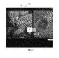
- FIG. 1is a schematic illustration of a display with a User Interface for defining proximity alert locations associated with avoid zones and/or target treatment sites using a patient anatomical model for MRI-guided procedures according to embodiments of the present invention.
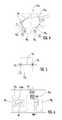
- FIG. 2is a schematic illustration of a display with a User Interface for defining avoid zones (and/or target treatment sites) using a patient anatomical model for MRI guided procedures according to embodiments of the present invention.
- FIG. 3is a display with a User Interface for defining avoid zones and/or target treatment sites according to embodiments of the present invention.
- FIG. 4is a schematic illustration of a non-limiting example of an exemplary number of different scan planes that are associated with a region of interest of a heart of a patient that can be used to obtain MR image data relevant to one or more target ablation paths during an interventional procedure according to embodiments of the present invention.
- FIG. 5is a schematic illustration of auto-defined boundary limits according to embodiments of the present invention.
- FIG. 6is a schematic illustration of a system configured to generate proximity alerts according to embodiments of the present invention.
- FIG. 7is a schematic of a display with a visualization showing a rendered patient model with an avoid zone and/or treatment site registered to 3-D MRI image space according to embodiments of the present invention.
- FIG. 8is a schematic illustration of an MRI-guided system configured to show a device-tissue interface using near RT MRI data according to embodiments of the present invention.
- FIG. 9is a schematic illustration of an intrabody device with a tracking coil electrically connected to a Scanner channel according to embodiments of the present invention.
- FIG. 10is a schematic illustration of an MRI system with a workstation and display according to embodiments of the invention.
- FIG. 11is a circuit diagram of an exemplary tracking coil tuning circuit according to embodiments of the present invention.
- FIGS. 12A-12Dare prophetic screen shots of exemplary interactive visualizations with a physical representation of an intrabody flexible medical device according to embodiments of the present invention.
- FIG. 13is a schematic illustration of a display with two viewing windows, one showing an interactive visualization and the other showing prophetic relevant near RT MRI image according to embodiments of the present invention.
- FIGS. 14 and 15are schematic illustrations of exemplary visualizations and images on a display and UI controls that can be generated to facilitate an MRI guided procedure according to embodiments of the present invention.
- FIG. 16is a schematic of a display having two viewing windows one showing target ablation sites on a patient model and the other showing contemplated (prophetic) near real time “close-up” MRI images of local tissue, at least the latter images may be generated using one or more pre-set scan planes according to embodiments of the present invention.
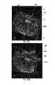
- FIGS. 17 and 18are screen shots showing axial and en face views showing prophetic examples of near real time “close-up” MRI images of local tissue that may be generated using one or more pre-set scan planes according to embodiments of the present invention.
- FIG. 19is a schematic illustration of an exemplary MRI cardiac interventional suite according to some embodiments of the present invention.
- FIG. 20Ais an enlarged partial perspective view of a tip portion of an exemplary ablation catheter according to particular embodiments of the present invention.
- FIG. 20Bis a cross-section of the tip portion of the catheter taken along lines 20 B- 20 B in FIG. 20A .
- FIG. 21is an enlarged axial cross section of a tip portion of another example of an ablation catheter according to embodiments of the present invention.
- FIG. 22is an enlarged cross-section of the catheter shown in FIG. 21 .
- FIG. 23is an enlarged cross-section of the catheter shown in FIG. 21 taken along lines 23 - 23 in FIG. 21 .
- the FIG. 22 section viewis taken at a location upstream of that shown in FIG. 23 .
- FIG. 24is a flow chart of exemplary operations that can be used to carry out embodiments of the present invention.
- FIG. 25is another flow chart of exemplary operations that can be used to carry out embodiments of the present invention.
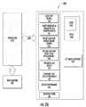
- FIG. 26is a schematic illustration of a data processing circuit or system according to embodiments of the present invention.
- circuitrefers to an entirely software embodiment or an embodiment combining software and hardware aspects, features and/or components (including, for example, at least one processor and software associated therewith embedded therein and/or executable by and/or one or more Application Specific Integrated Circuits (ASICs), for programmatically directing and/or performing certain described actions or method steps).
- the circuitcan reside in one location or multiple locations, it may be integrated into one component or may be distributed, e.g., it may reside entirely in an MR Scanner control cabinet, partially in the MR Scanner control cabinet, totally in a separate component or system such as a clinician workstation but communicate with MR Scanner electronics and/or in an interface therebetween, in a remote processor and combinations thereof.
- pre-set scan planerefers to scan planes electronically (programmatically) defined for subsequent use by an MRI Scanner as being associated with a location of relevant anatomical tissue of a patient during a MRI guided therapeutic or diagnostic procedure.
- the pre-set scan planescan be defined based on one or more volumetric models or maps of patient anatomical structure that is subsequently registered or aligned in 3-D imaging space and can be used to acquire near real-time MR image data of patient tissue.
- tissue characterization maprefers to a rendered visualization or image of one or more selected parameters, conditions, or behaviors of cardiac tissue using MR image data, e.g., the tissue characterization map is a rendered partial or global (volumetric) anatomical map that shows at least one defined tissue characteristic of the heart in a manner that illustrates relative degrees or measures of that tissue characteristic(s), typically in different colors, opacities and/or intensities.
- the tissue characterization mapis to be contrasted with an electroanatomical tissue map which is based on sensed electrical activity of different regions of the heart rather than on MR image data.
- the planning map and/or subsequent visualizationscan use one or both types of volumetric maps.
- the planning map and/or visualizationscan use one or both types of volumetric tissue maps, shown separately, overlaid on each other and/or integrated (e.g., superimposed) as a composite map.
- tissue data from an electroanatomical map and/or the tissue characteristic mapcan be selectively faded or turned on and off with respect to a pre-acquired map/model of the patient's anatomical structure (e.g., Left Atrium).
- the terms “fade” and “faded”refer to making the so-called feature less visually dominant in a visualization and/or planning map by dimming the intensity, color and/or opacity relative to other features in the visualization.
- the actual visualizationcan be shown on a screen or display so that the map or anatomical structure is in a flat 2-D and/or in 2-D what appears to be 3-D volumetric images with data representing features or electrical output with different visual characteristics such as with differing intensity, opacity, color, texture and the like.
- a 4-D mapcan either illustrate a 3-D heart with movement (e.g., a beating heart and/or a heart with blood flow) or show additional information over a 3-D anatomic model of the contours of the heart or portions thereof.
- 4-D multiparametric visualizationmeans a 4-D visualization (e.g., a 3-D image of a beating heart) with functional spatially encoded or correlated information shown on the visualization.
- the 4-DMP visualizationcan be provided with fMRI data and/or one or more tools used to provide the spatially correlated functional data (e.g., electrical, DHE) data of the heart based on a 3-D model.
- the 3-D, 4-D and/or 4-DMP visualizationsare not merely an MRI image or MRI images of the patient but are rendered visualizations that can combine multiple sources of data to provide a visualization of spatially encoded function with anatomical shape.
- the visualizationscan comprise a rendered model of the patient's target anatomy with a rendered visualization of at least one medical device in an intrabody location with respect to the model and along with near RT MRI image data of the anatomical structure.
- the figuresmay include prophetic examples of screen shots of visualizations and the like and do not necessarily represent actual screen shots of a display.
- close-upmeans that the associated image is shown enlarged relative to a global image or map view to show local tissue.
- high-resolutionmeans that the image data is obtained with higher resolution than normal image data (usually requiring longer scan times and/or using an internal antenna to increase SNR).
- the local tissue ablation viewsmay be shown in higher resolution than real-time MRI images in the navigation view.
- en facerefers to a view through a tissue wall (e.g., myocardial wall) and parallel (or tangent) to the surface.
- programmeans that the operation or step can be directed and/or carried out by a digital signal processor, computer program code and/or an Application Specific Integrated Circuit (ASIC).
- ASICApplication Specific Integrated Circuit
- electrotronicallymeans that the step or operation can be carried out in an automated manner using electronic components rather than manually or using merely mental steps.
- target ablation pathdescribes a desired lesion pattern that is selected to create a desired electrical isolation in the cardiac tissue to treat the at-risk pathology/condition (e.g., atrial fibrillation).
- the target ablation pathis not required to be followed in any particular direction or order.
- the pathmay include one or more continuous lesions and/or several non-continuous or non-contiguous lesions.
- the lesionsmay be linear (whether straight or with a curvature such as circular or curvilinear).
- the physiciancan define one or more target paths to create the desired pattern/isolation.
- the target ablation pathcan be used to electronically define physical limits associated with the acceptable maximum boundary limits (e.g., width, perimeter and the like) of a site and/or the target ablation path.
- proximity alertrefers to a proximity alert that can be generated as an audible and/or visual alert when an intrabody medical device is approaching or is in a correct location.
- warning proximity alertrefers to a proximity alert that can be generated as an audible and/or visual alert when an intrabody medical device is in an incorrect position, such as outside boundary limits of a target treatment or diagnostic site or proximate an avoid zone.
- different audible and/or visual warning alertscan be used to distinguish the warning alerts from the confirmation alerts to provide user feedback that indicates whether the device is outside boundary limits or proximate an avoid zone or in a proper location.
- an intrabody medical devicecan be tracked and its position electronically identified in 3-D MR imaging space (e.g., X, Y, Z coordinates).
- 3-D MR imaging spacee.g., X, Y, Z coordinates
- the intrabody devicecan include fiducial markers or receive antennas combinations of same.
- fiducial markerrefers to a marker that can be identified using electronic image recognition, electronic interrogation of MRI image data, or three-dimensional electrical signals to define a position and/or find the feature or component in 3-D space.
- the fiducial markercan be provided in any suitable manner, such as, but not limited to a geometric shape of a portion of the tool, a component on or in the tool, a coating or fluid-filled coating (or combinations of different types of fiducial markers) that makes the fiducial marker(s) MRI-visible that are active or passive (e.g., if passive, the marker does not provide MR signal) with sufficient intensity for identifying location and/or orientation information for the tool and/or components thereof in 3-D space.
- a coating or fluid-filled coatingor combinations of different types of fiducial markers
- the devicecomprises at least one tracking coil electrically connected to a respective channel of the MRI Scanner that generate signals that are detected (received) by the MR Scanner and used to identify respective locations of the coils in a 3-D coordinate system of the imaging space, and hence the device with such tracking coils, in the 3-D image space.
- MRI or MR Scannerare used interchangeably to refer to a Magnetic Resonance Imaging system and includes the magnet, the operating components, e.g., RF amplifier, gradient amplifiers and operational circuitry including, for example, processors or ASICs (the latter of which may be held in a control cabinet) that direct the pulse sequences, select the scan planes and obtain MR data.
- operating componentse.g., RF amplifier, gradient amplifiers and operational circuitry including, for example, processors or ASICs (the latter of which may be held in a control cabinet) that direct the pulse sequences, select the scan planes and obtain MR data.
- RF safemeans that the catheter and any conductive lead is configured to operate safely when exposed to RF signals, particularly RF signals associated with MRI systems, without inducing unplanned current that inadvertently unduly heats local tissue or interferes with the planned therapy.
- MRI visiblemeans that the device is visible, directly or indirectly, in an MRI image. The visibility may be indicated by the increased SNR of the MRI signal proximate the device.
- the devicecan act as an MRI receive antenna to collect signal from local tissue and/or the device actually generates MRI signal itself, such as via suitable medical grade hydro-based coatings, fluid (e.g., aqueous fluid) filled channels or lumens.
- MRI compatiblemeans that the so-called component(s) is safe for use in an MRI environment and as such is typically made of a non-ferromagnetic MRI compatible material(s) suitable to reside and/or operate in a high magnetic field environment.
- high-magnetic fieldrefers to field strengths above about 0.5 T, typically above 1.0 T, and more typically between about 1.5 T and 10 T. Embodiments of the invention may be particularly suitable for 1.5 T and/or 3.0 T systems.
- vasculaturerefers to a curvilinear pathway in the body, typically associated with a natural lumen such as vasculature.
- dynamic visualizationsrefers to a series of visualizations that show the movement of the device(s) in the body and can show a beating heart or movement based on respiratory cycle and the like.
- pre-acquiredmeans that the data used to generate the model or map of the actual patient anatomy can be obtained prior to the start of an active therapeutic or diagnostic procedure and can include immediately prior to but during the same MRI session or at an earlier time than the procedure (typically days or weeks before).
- Embodiments of the present inventioncan be configured to guide and/or place intrabody diagnostic and/or interventional devices in an MRI environment (e.g., interventional medical suite) to any desired internal region of interest of a subject, typically via a natural lumen and/or tortuous path so that the intrabody devices can take on different non-linear configurations/shapes as it moves into position through a target pathway (which may be a natural lumen or cavity).
- the subjectscan be animal and/or human subjects.
- Some embodiments of the inventionprovide systems that can be used to ablate tissue for treating arrhythmias such as atrial fibrillation, to repair or replace cardiac valves, repair, flush or clean vasculature and/or place stents, and/or to deliver stem cells or other cardio-rebuilding cells or products into cardiac tissue, such as a heart wall, via a minimally invasive MRI guided procedure while the heart is beating (i.e., not requiring a non-beating heart with the patient on a heart-lung machine).
- the cardiac procedurescan be carried out from an inside of the heart or from an outside of the heart.
- the planning map 137 pcan be an electroanatomical map, a tissue characterization map, an MRI image or combinations of same.
- the mapis rendered to represent portions or regions of the heart, such as the left atrium and any adjacent vasculature of interest (e.g., the branching of the pulmonary veins), the ventricles and the like.
- the cardiac proceduresmay be directed to treating cardiac disorders such as arrhythmias or heart failure (e.g., congestive heart failure, reduced heart function, and the like).
- inventionsprovide systems suitable for delivering a therapeutic agent or carrying out another treatment or diagnostic evaluation for any intrabody location, including, for example, the brain, gastrointestinal system, genourinary system, spine (central canal, the subarachnoid space or other region), vasculature or other intrabody locations. Additional discussion of exemplary target regions can be found at the end of this document.
- the systemscan be configured so that the surgical space is the (MRI) imaging space and the tracking is performed in the imaging space so that there is no requirement to employ a discrete tracking system that must then be registered to the imaging space.
- the trackingis carried out in the same 3-D imaging space but the flexible intrabody medical device is tracked independent of the imaging scan planes used to obtain the MR image data for generating images of local anatomy and is shown as a physical representation in the visualization.
- the systemscan be configured to work with robotic systems or non-robotic surgical systems.
- the term “near real time”refers to both low latency and high frame rate. Latency is generally measured as the time from when an event occurs to display of the event (total processing time).
- the frame ratecan range from between about 100 fps (frames per second) to the imaging frame rate. In some embodiments, the tracking is updated at the imaging frame rate.
- the frame rateis typically between about 1 fps to about 20 fps, and in some embodiments, between about 3 fps to about 7 fps.
- a new imagecan be generated about every 1-7 s, depending on the sequence used.
- the low latency required to be considered “near real time”is generally less than or equal to about 1 second.
- the latency for tracking informationis about 0.01 s, and typically between about 0.25-0.5 s when interleaved with imaging data.
- visualizations with the location, orientation and/or configuration of a known intrabody devicecan be updated with low latency between about 1 fps to about 100 fps.
- visualizations using near real time MR image datacan be presented with a low latency, typically within between about 0.01 ms to less than about 1 second, and with a frame rate that is typically between about 1-20 fps.
- the systemcan use the tracking signal and image signal data to dynamically present anatomy and one or more intrabody devices in the visualization in near real-time.
- the tracking signal datais obtained and the associated spatial coordinates are determined while the MR image data is obtained and the resultant visualization(s) with the intrabody device (e.g., flexible catheter using the tracking coil data) and the near RT MR image(s) is generated.
- the intrabody devicee.g., flexible catheter using the tracking coil data
- MR image datais obtained during an active treatment such as during an ablation, delivery of a drug or other material, valve repair or replacement, lining repair, and the like, and the resultant visualization(s) with the flexible intrabody device used for this treatment (e.g., catheter, needle and the like) along with one or more near RT MR images of local anatomy is substantially continuously generated.
- active treatmentsuch as during an ablation, delivery of a drug or other material, valve repair or replacement, lining repair, and the like
- the resultant visualization(s) with the flexible intrabody device used for this treatmente.g., catheter, needle and the like
- intrabody deviceis used broadly to refer to any diagnostic or therapeutic medical device including, for example, catheters, needles (e.g., injection, suture, and biopsy), forceps (miniature), knives or other cutting members, ablation (cryo, ultrasound, RF with single or multiple ablation (array) electrodes) or stimulation probes, injection or other fluid delivery cannulas, mapping or optical probes or catheters, sheaths, guidewires, fiberscopes, dilators, scissors, implant material delivery cannulas or barrels, and the like, typically having a flexible body and/or having a size that is typically between about 5 French to about 12 French, but other sizes may be appropriate.
- catheterse.g., injection, suture, and biopsy
- forcepsminiature
- knives or other cutting memberse.g., ablation (cryo, ultrasound, RF with single or multiple ablation (array) electrodes) or stimulation probes
- injection or other fluid delivery cannulase.g.,
- exemplary flexible devices 80are shown for tracking coils for transseptal needles (septal puncture kit components) and mapping and/or ablation catheters for cardiac use, embodiments of the invention are not intended to be limited to these devices nor to cardiac use.
- the devicescan be implemented as injection catheters or diagnostic biopsy needles and the like for any target anatomical location in the body. See, e.g., U.S. patent application Ser. No. 10/769,994 (intramyocardial injection needle), U.S. Pat. No. 7,236,816 (biopsy needle), and U.S. Pat. No.
- FIG. 1is an example of a display 20 with a User Interface (UI) 25 with at least one UI control 25 c and a volumetric planning model 137 p of an exemplary target anatomical structure of a patient (e.g., it is patient-specific and is shown here as the patient's heart).
- the planning model 137 pcan be rendered using any patient-specific data in a volumetric map 100 M, including, for example, an electroanatomical map/model, a tissue characteristic map/model or combinations of same.
- the planning model or map 137 pcan comprise a global model or a series of segmented or otherwise apportioned models of portions of relevant anatomy, e.g., the left atrium and right atrium (and/or pulmonary ventricles, pulmonary vein ostia, esophagus, aorta, fossa ovalis, and the like) may be shown on separate maps and/or on a global planning map.
- FIG. 2illustrates a partial cutaway version of a planning map or model 137 p.
- the planning model 137 pcan accept user input via a user interface (UI) 25 with at least one UI control 25 c to identify, select, define and/or “mark” at least one avoid zone 155 and/or at least one target treatment site 55 t using (e.g., marked on) the planning model 137 p .
- the UI control 25 ccan include a touch screen input, or other user selectable input that can be activated such as when in a planning mode, e.g., turned “on” and/or “off”.
- electroanatomical and/or tissue characteristic datacan be turned “on” or “off” or faded on the model 137 p .
- An avoid zone 155is typically associated with susceptible or sensitive areas that should be avoided during insertion of a medical device along an intrabody path and/or at the target end location (e.g., the aorta during a transseptal entry) or certain regions of the anatomical structure that should not be treated (e.g., ablated) during active treatment (e.g., ablation).
- the avoid zone 155is associated with a posterior wall of the left atrium (where the esophagus touches the posterior wall). If shown in the patient planning model 137 p , the esophagus would be a long tube rising above the posterior wall of the left atrium just above the viewer 141 (panel).
- the atrioventricular (AV) node of the patient's heartis identified as an avoid zone 155 .
- the map 137 pcan be used to mark the aorta as the avoid zone 155 and the target site 55 t can be the fossa ovalis, which may be suitable for certain cardiac procedures carried out via a tortuous path using a transseptal needle to place an access port as is well known.
- the planning map(s) 137 pcan be used to indicate a number of avoid zones 155 , such as, for example, a portion of an esophagus adjacent a cardiac posterior wall, an aorta, a phernic nerve, and an atrioventricular (AV) node of the patient's heart.
- avoid zones 155such as, for example, a portion of an esophagus adjacent a cardiac posterior wall, an aorta, a phernic nerve, and an atrioventricular (AV) node of the patient's heart.
- AVatrioventricular
- the planning map 137 p with the marked or selected avoid zones 155can be electronically registered to 3-D MRI image space prior to or at the start of a procedure.
- the circuit 60 cFIG. 9
- the circuit 60 ccan automatically generate proximity alerts 90 ( FIG. 6 ) when one or more tracked intrabody devices 80 ( FIGS. 8-10 ) is at a location that is proximate a defined avoid zone(s) 155 .
- the proximity alert 90can be an audible and/or visual warning proximity alert.
- the alert 90can be shown on the navigation view of the display (and output via speakers associated with the display) or may be provided by an external audiovisual alert provided to the clinician (physician) in the MRI suite.
- FIG. 1also illustrates that the display can have a UI control 25 c for a Plan Treatment (e.g., Ablation path 55 p ) input.
- Plan Treatmente.g., Ablation path 55 p
- This inputallows a user/physician to select one or more target sites 55 t ( FIG. 1 ) for active treatment or diagnosis.
- boundary limits 55 l ( FIG. 5 ) for a respective target site 55 tcan also be defined.
- a proximity alert 90can be generated when a known intrabody device is within the boundary limits 55 l proximate a selected treatment site 55 t .
- a proximity alert 90may also be generated when the known intrabody device is approaching or proximate a selected treatment site but outside the defined boundary limits 55 l .
- the pitch of an audible tone or some parameter of a displayed indicatormay change to indicate the distance between the tip of the intrabody device and a target.
- the avoid zone proximity (warning) alert 90can be generated using the identified zone 155 on the planning map 137 p (registered to 3-D MRI imaging space), the tracked location of the intrabody device in 3-D MRI imaging space, and known physical data regarding the form and/or features of the intrabody device (e.g., distance of the tip from the tracking coil(s)).
- the treatment site alerts 90can be generated based on the identified treatment site 55 t on the planning map 137 p , the defined associated boundary limits 55 l , the tracked location of the intrabody device in 3-D MRI imaging space, and known physical data regarding the form and/or features of the intrabody device (e.g., distance of the tip from the tracking coil(s)).
- More than one intrabody devicecan be tracked in the body during the MRI-guided procedure and the alert(s) 90 can be generated whenever any such device is in an avoid zone or other proximity alert location.
- the altersmay be configured to “focus” on the location or motion of one particular device or a visual alert may be assigned to one device while an audible alert may be assigned to another device or different sets of visual and audible alerts can be associated with each respective tracked device.
- the systemcan electronically associate pre-set scan planes for a respective selected treatment site 55 t for use by an MR Scanner during the MRI-guided procedure. That is, the model 137 p can be used to place relevant imaging slices on tissue having a certain spatial relationship to a feature (e.g., tip) of a known device 80 and those imaging slices may have certain predefined orientations for most advantageous viewing of the tissue or lesions within.
- a featuree.g., tip
- the Plan Treatment UI control 25 ccan allow a clinician/physician to select a desired ablation path that is intended to electrically isolate one or more regions of interest of cardiac tissue.
- the target ablation path 55 pcan be one continuous path or several discontinuous paths in a region of interest (ROI).
- the planning model 137 p with both or either one of the avoid zone input mode and the plan treatment site input modemay be particularly suitable for use during a pre-procedure planning stage of an interventional procedure or at an evaluation stage prior to conclusion of a procedure.
- the planning map 137 pis “tagged”, meaning electronically associated/loaded with the selected treatment sites 55 t and/or the avoid zones 155 , such that the proximity alert sites/zones are electronically locked to the planning map 137 p prior to the interventional surgery.
- the planning map 137 pis then typically registered to 3-D MRI imaging (coordinate) space ( FIG. 7 ) prior to start of an MRI-guided interventional procedure which places the marked sites 55 t and avoid zones 155 in the correct location in the 3-D MRI imaging space.
- the UItypically includes multiple GUI controls 25 c that can include a touch screen and/or mouse or other input control to allow a physician to select a region of interest in the map 137 p by placing a cursor or by touching the screen at a region of interest.
- Thiscan cause the system to define a corresponding avoid zone 155 , define a target treatment site 55 t , calculate boundary limits 55 l ( FIG. 5 ) (e.g., maximum acceptable boundary positions for an ablation location), and optionally electronically define preset scan planes 141 ( FIG. 1 ) for use during an interventional procedure.
- the systemcan be configured to provide a list and/or overlay of suggested avoid zones 155 for a particular medical procedure or for target anatomical structure for treatment (and/or the access path used to reach this structure).
- a usercan select one or more of the suggested avoid zones 155 and the system can automatically virtually place these zones on the planning map 137 p (using fiducial markers or anatomical markers) and the like.
- the systemcan show a proposed avoid zone on the planning map 137 p and allow a user to use a UI control 25 c to move the location or adjust the size or shape of the suggested avoid zone 155 on the planning map 137 p which may vary patient to patient as well as procedure to procedure.
- a usermay optionally affirmatively lock the avoid zone to the planning map 137 p .
- a lock icon or other UI control 25 cmay be used for facilitating the avoid zone selection.
- the avoid zonescan be automatically locked.
- one or more scan plane identifier pointscan be virtually (automatically and/or manually) be placed on the planning map 137 p and can be used to define relevant associated scan plane(s) 141 .
- one point/treatment site 55 tcan be placed or indicated on the planning map 137 p by a user and the system 10 can automatically suggest one or more planes that cover this site 55 t , and may electronically evaluate local anatomical contour to do so.
- a clinicianmay mark fiducials to facilitate the scan plane selection and/or the circuit may be configured to electronically identify anatomical fiducials to identify a position on the model and/or select suggested scan planes associated with a target site that can be used as the actual pre-set scan plane 141 or may facilitate identification or selection of an appropriate scan plane or maybe established as the pre-set scan plane(s) 141 .
- a usercan define the relevant scan planes for one or more sites 137 p by affirmatively indicating the desired scan plane(s) using a UI control (e.g., GUI),
- a usercan virtually mark two or more points that can be used by the circuit to automatically define the pre-set scan planes 141 used to obtain relevant image slices.
- the automatically selected/defined pre-set scan planes 141can be shown visually on/through the model 137 p .
- a usermay adjust the automatically selected scan planes 141 if desired.
- the UImay be configured to allow the user to affirmatively “lock” a scan plane(s) 141 for each treatment site 55 t (and/or avoid zone 155 ) to electronically associate them with the planning model 137 p for future use by an MR Scanner 10 S.
- the planning map 137 pis used to identify at least one avoid zone 155 and/or relevant target treatment/diagnostic sites 55 t (and optionally associated scan planes 141 shown as one projected scan plane in FIG. 1 ) in a pre-surgical planning procedure before the actual MRI-guided surgery.
- the at least one avoid zone 155 and/or at least one target treatment site 55 tcan be selected without requiring that the planning map 137 p be registered to a 3-D (e.g., X, Y, Z) coordinate system associated with MRI imaging space.
- the system 10can be configured to electronically automatically or manually (such as via a clinician using the display) register the planning map 137 p to the 3-D MRI imaging space and electronically identify proximity alert locations associated with one or more previously identified avoid zones 155 and/or one or more previously identified target treatment sites 55 t.
- the map 137 pcan be shown with orthogonal or oblique viewing planes or panels 41 , 42 that can allow a user to rotate the map during the planning procedure and/or during the MRI-guided procedure.
- FIG. 4illustrates that the system can use the map 137 p to define a plurality of different scan planes 70 1 - 70 n , shown as with at least six (6) scan planes, one or more of which can be automatically electronically associated with a respective target treatment site(s) 55 t , such as an ablation path 55 p selected in FIG. 1 .
- the six scan planes shownare merely an example of a number of different scan planes that may be used. In practice, more or less scan planes may be used for a particular path or ROI (portion) of a heart. Any scan plane can be temporarily disabled to allow faster update of the remaining scan planes.
- FIG. 5illustrates one ablation path 55 p associated with scan plane 3 ( 70 3 ).
- the system 10can automatically calculate and set boundary limits 55 l on boundaries for a target ablation path 55 p (e.g., a catheter drag path).
- a target ablation path 55 pe.g., a catheter drag path.
- an audible or visual proximity alert 90can be generated.
- embodiments of the inventionare directed to User Interfaces (UI) for clinical workstations that facilitate control of scan planes used to obtain relevant MR image data for efficient workflow and/or automation of image generation during the interventional procedure.
- UIUser Interfaces
- Embodiments of the inventioncan also or alternatively provide near real time alerts regarding deviation from a planned treatment path during an interventional procedure.
- the boundary limits 55 lcan be determined based on the scan plane.
- a proposed ablation drag path 55 pcan be plotted on the 3D map 137 p of the region of interest (ROI), such as a left atrium (LA).
- ROIregion of interest
- LAleft atrium
- the systemcan then programmatically determine the scan planes that fall within the proposed path.
- the auto-limits on the boundaries of the ablation path 55 pare then set based on the particular scan plane: X mm/cm of the path fall in scan plane 1 ; Y mm/cm of the path fall in scan plane 2 ; etc. These dimensions can be used to determine the boundary limits 55 l .
- the systemcan be configured so that the Scanner will pull up the next scan plane automatically based on the location of the tip (or distal end portion) of the intrabody device, e.g., ablation catheter.
- the boundary limits 55 lcan be defined based on a predetermined distance outside the boundary limits of the selected target path, e.g., X mm from a known coordinate position of the target site 55 t or path 55 p .
- a default boundary limit 55 lis applied (e.g., between about 0.01 mm to about 4 mm, typically between about 1-2 mm from a marked site 55 t ).
- a usercan define the boundary limits 55 l based on the actual treatment site or treatment type.
- the user-defined boundary limits 55 lcan be based on a pull-down menu of suggested limits or a user may enter desired limit dimensions via a UI such as a keyboard or voice prompt and the like.
- FIG. 6illustrates that as a physician prepares to ablate tissue proximate one target ablation site 55 t along the path 55 p , a close-up ablation view is generated using an associated scan plane, for example, 70 3 .
- the ablation catheter 80is not where it is expected to be in the close-up side view MRI 35 (a substantially real-time MRI of local tissue taken from a scan plane extending axially along the ablation catheter and projected a distance forward therefrom) to create the lesion at the desired ablation location (not within the target path boundary limits 55 l ).
- a visual and/or audible proximity alert 90can be generated, shown as using the workstation display 20 and/or speakers.
- FIG. 6also shows the display 20 can include side-by-side viewing windows 35 a , 35 b one showing the map 137 p or other anatomical patient model 100 M (typically used during navigation mode and ablation mode) 35 a and the other view 35 b with images of local tissue during an ablation mode using near real time MR image data during ablation, typically showing a side view of the local tissue and ablation catheter 80 according to embodiments of the present invention.
- side-by-side viewing windows 35 a , 35 bone showing the map 137 p or other anatomical patient model 100 M (typically used during navigation mode and ablation mode) 35 a and the other view 35 b with images of local tissue during an ablation mode using near real time MR image data during ablation, typically showing a side view of the local tissue and ablation catheter 80 according to embodiments of the present invention.
- Embodiments of the inventionare directed to allow a physician to “drag” an ablation catheter or other ablation source, typically “back and forth”, along a target defined ablation path 55 p while information on the location of the ablation catheter 80 ( FIGS. 20A-23 ) and/or target tissue is provided to the user/physician. If the catheter 80 or other source is out of position with respect to a defined target path 55 p and the associated boundaries 55 l , the system 10 can generate an audible and/or visual warning proximity alert 90 prior to when an ablation lesion is formed.
- the system 10facilitates cardiac ablation under MRI guidance using a “catheter dragging” approach while applying energy, e.g., RF, heat, optical, light, ultrasound or other energy for ablation.
- energye.g., RF, heat, optical, light, ultrasound or other energy for ablation.
- a 3-D volumetric map 13 ′ 7 p of at least the left atrium (LA), of a patientcan be generated during, but typically prior to, an active interventional EP cardiac procedure.
- the system 10can be configured to programmatically automatically define a minimum number of scan planes to cover associated intracardiac surfaces targeted for ablation. A physician can modify the number of scan planes if desired.
- These scan planes 70 ncan be preset for use during the interventional procedure as described above.
- the systemcan electronically/programmatically associate/define boundary limits for the drag lesion, thus setting automatic limits on boundaries of a suitable catheter drag path.
- These auto-limited 55 l drag paths 55 pcan be electronically defined and incorporated into a procedure plan.
- scan planes 70 1 - 70 6are automatically used to generate MR image data as a catheter nears a location to ablate associated with a location in the planned target ablation path 55 p .
- a physicianfollows the defined target ablation paths 55 p and does not exceed the limits indicated on the path (to keep from going out of the scan plane). If a tip and/or distal end portion of the catheter 80 goes outside the associated defined scan plane, a proximity alert (alarm) can be generated.
- the MR Scanner 10 Sobtains near real-time MR images in the preset scan plane and the physician can see the “drag lesion” as it is created, such as in viewing window 20 w 2 ( FIGS. 16 , 17 ).
- the system 10can be configured to automatically electronically lock the ablation source “off” if the catheter 80 is determined to be out of position relative to one of the boundary limits of a respective predefined target ablation path 55 p .
- a cliniciancan override the lock status to ablate the local tissue and a scan plane can be adjusted to allow him or her to view this tissue as a close-up MRI ( FIGS. 16 , 17 ) or the physician may elect to move the catheter into the desired bounds and the catheter 80 will be shown in position using the pre-set scan plane.
- the ablation catheter 80can include tracking coils or other features that allow the system to register the location of the catheter in space and show it in position on the map 100 M.
- the map 137 p and/or 100 Mcan be in grey scale and/or color-coded to provide an easy to understand map or image with different ablation, injection or other treatment sites/paths and/or tissue characterizations shown in different colors and/or with different degrees of a particular characterization shown in gray scale.
- color-codedmeans that certain features or conditions, such as ablated versus non-ablated tissue, target ablation sites and actual ablation sites and the like, are shown with colors of different color, hue or opacity and/or intensity to visually accentuate different conditions or status of tissue or different and similar tissue, such as, for example to show lesions in tissue versus normal or non-lesion tissue or fluid treated tissue versus non-treated tissue for an injection therapy.
- the UI control 25 ccan be configured to allow a clinician to increase or decrease the intensity or change a color of certain tissue characterization types, e.g., to show lesion tissue or tissue having edema with a different viewing parameter, e.g., in high-contrast color and/or intensity, darker opacity or the like.
- a lesion site(s) in the tissue characteristic map 100 Mcan be defined based on an ablation position in three-dimensional space (e.g., where an electrode is located based on location detectors, such as tracking coils, when the ablation electrode is activated to ablate), but is typically also or alternately associated with MRI image data in associated scan planes to show an ablation site(s) in an MRI image.
- the MR image datamay also reflect a change in a tissue property after or during ablation during the procedure, e.g., Delayed Hyper Enhancement (DHE), thermal, edema and the like.
- DHEDelayed Hyper Enhancement
- the UI control 25 ccan allow the clinician to request a high resolution or enlarged view of the actual ablated tissue merely by indicating on the map a desired region of interest (e.g., by pointing a finger, cursor or otherwise selecting a spot on the display). For example, a high resolution MR image of suspect tissue in the left superior pulmonary vein (LSPV) can be shown so that the physician can see actual tissue in the desired spot indicated on the map.
- New targetscan be marked on the map as needed ( FIG. 18 ) and again, pre-set scan planes and/or boundary limits can be automatically electronically associated with the new targets by location.
- the system 10( FIGS. 8-10 ), e.g., a circuit 60 c associated with (e.g., that communicates with or is integral to) the MRI Scanner 10 S ( FIGS. 9-10 ) can generate proximity alerts 90 when a known (the system includes dimensional and/or configuration data of the device) intrabody device 80 is proximate the at least one avoid zone 155 and/or inside or outside boundary limits of the at least one target treatment site 55 t .
- the system 10can also optionally automatically use one or more pre-set scan planes 141 during the surgical procedure when the known intrabody device 80 approaches or is in proximity to a defined corresponding target treatment site 55 t.
- the system 10can interact with the intrabody device 80 to select a relevant pre-set scan plane 141 (coronal, sagittal, transverse) corresponding to a tracked location of a distal end portion of the intrabody device.
- the pre-set scan plane(s) 141 used during the MRI-guided procedureis selected based on defined projected distance beyond a distal tip of the intrabody device 80 (axial and/or perpendicular to the distal end portion of the device) in near real time during an MRI-guided surgical procedure.
- the scan planescan image tissue proximate but beyond the tip of the device such as between about 0-4 mm, typically about 1-2 mm.
- the systemmay automatically enable or disable ECG gating as necessary when defining scan planes, markers, recording electrograms, and the like.
- FIG. 7illustrates a display 20 with a visualization 100 v that includes the planning map 137 p registered to the imaging space along with MRI image data 100 MRI that an MR Scanner 10 S can obtain while a patient is in the MR Scanner 10 S typically just prior to or at the start of the MRI-guided interventional procedure.
- the systemcan be configured to allow a user to “turn on” and/or “off” or fade the planning map 137 p or other model 100 M and/or the avoid zones 155 or target ablation sites 55 t or use a different volumetric map (both generally referred to using feature 100 M) of the patient in the visualization 100 v during the MRI-guided procedure.
- the planning map 137 pcan be imported and electronically interrogated to define the proximity alert locations adjusted to reflect the model registered to the 3-D imaging space.
- the identification of the proximity alert locationscan be “in the background” or shown on the display.
- the display 20can include a UI 25 c that allows a user to select whether to show the planning map 137 p on the display (typically as part of the visualization 100 v ) and/or to cause the system to identify and correlate the proximity alerts 90 for use during the MRI-guided procedure.
- FIG. 8illustrates an MRI interventional system 10 with a scanner 10 S and a (typically flexible) intrabody medical device 80 proximate target tissue 100 at a device-tissue interface 100 i .
- the system 10can be configured to electronically track the 3-D location of the device 80 in the body and identify and/or “know” the location of at least the tip portion of the device 80 t (e.g., the ablation or needle tip) in a coordinate system associated with the 3-D MRI imaging space.
- the display 20can be provided in or associated with a clinician workstation 60 in communication with an MRI Scanner 10 S.
- the MRI Scanner 10 Stypically includes a magnet 15 in a shielded room and a control cabinet 11 (and other components) in a control room in communication with electronics in the magnet room.
- the MRI Scanner 10 Scan be any MRI Scanner as is well known to those of skill in the art. Examples of current commercial scanners include: GE Healthcare: Signa 1.5 T/3.0 T; Philips Medical Systems: Achieva 1.5 T/3.0 T; Integra 1.5 T; Siemens: MAGNETOM Avanto; MAGNETOM Espree; MAGNETOM Symphony; MAGNETOM Trio.
- the workstation 60can include the circuit 60 c (e.g., ASIC and/or processor with software) that includes or executes part or all of the computer readable program code for generating the pre-set scan planes and/or identifying the pre-set scan planes.
- the circuit 60 ccan reside in the MRI Scanner 105 , the interface 44 (where used) and/or in one more remote processors.
- an MRI scanner interface 44may be used to allow communication between the workstation 60 and the scanner 105 .
- the interface 44may reside partially or totally in the scanner 105 , partially or totally in the workstation 60 , or partially or totally in a discrete device (shown in broken line in FIG. 10 ).
- the display 20can be configured to generate visual and/or audio proximity alerts 90 and render or generate near real time visualizations 100 v of the target anatomical space using MRI image data and can illustrate at least one intrabody device 80 in the space.
- the at least one intrabody device 80can comprise one or more tracking coils, passive markers and/or a receive antenna (or combinations of the above).
- the intrabody device 80can include a plurality of spaced apart tracking members 82 on a distal end portion thereof.
- the device 80can be an ablation catheter and the distal end portion 80 d , typically tip 80 t , can include an electrode or other therapy device 80 e (typically at least one at a distal end portion of the device).
- the electrodecan be either or both a sensing and ablation electrode.
- the tracking members 82can comprise miniature tracking coils, passive markers and/or a receive antenna.
- the tracking members 82include at least one miniature tracking coil 82 c that is connected to a channel 10 ch of an MRI Scanner 10 S ( FIGS. 9 , 10 ).
- the MR Scanner 10 Scan be configured to operate to interleave the data acquisition of the tracking coils with the image data acquisition.
- the tracking datais typically acquired in a ‘tracking sequence block’ which takes about 10 msec (or less).
- the tracking sequence blockcan be executed between each acquisition of image data (the latter can be referred to as an ‘imaging sequence block’). So the tracking coil coordinates can be updated immediately before each image acquisition and at the same rate.
- the tracking sequencecan give the coordinates of all tracking coils simultaneously. So, typically, the number of coils used to track a device has substantially no impact on the time required to track them.
- Embodiments of the present inventionprovide a new platform that can help facilitate clinical decisions during an MRI-guided procedure and can present near real time anatomical image data to the clinician in a visualization 100 v .
- the visualizations 100 v( FIGS. 12A-12D ) can be interactive and dynamically generated as the intrabody device 80 moves in the body into a target location, as a user rotates, crops or otherwise alters a displayed visualization or view and/or during an active therapy or diagnostic procedure step, e.g., while ablating at target lesion sites or while injecting (or performing another therapy) tissue, with minimal latent time between serial MRI image data acquisitions, typically less than about 5 seconds, typically substantially continuously with a minimal latent time of about 1 second or less, such as between about 0.001 seconds and 1 second.
- the system 10can use the tracking signal(s) and image signal data to dynamically track the device 80 (which is typically a plurality of devices) and present visualizations of the anatomy and one or more intrabody devices 80 in near real-time.
- the deviceis tracked in 3-D MRI images space but is not required to be in any of the relevant anatomical scan planes used to obtain MR data for the near RT MRI images.
- the term “physical representation”means that the device 80 is not actually imaged but rather is rendered with a physical form in the visualizations, typically with a three-dimensional shape or form.
- the physical representationis a partial physical representation which shows the distal end portion of the device in the body in the 3-D MR image space.
- the physical representation 80 Rmay be of any form including, for example, a graphic with at least one geometric shapes, icons and/or symbols.
- the physical representationmay be a virtual graphic substantial replica substantially corresponding to an actual shape and configuration of the actual physical appearance and/or configuration of the associated device (see, e.g., FIGS. 3 , 12 A- 12 D, 14 ).
- the physical representation 80 Rcan be electronically generated based on a priori knowledge of the dimensions and configuration of the device (and where the shape can vary, known form factors or a predicable or known change in shape),
- the tip and each tracking coil on a distal end of a particular devicemay be shown in a geometric shape (the same or different shapes, e.g., an arrow for the tip and a sphere or block or other (typically 3-D) geometric shape or shapes for tracking coils, each in its real location in the 3-D space and in its relative position on the device and each may be rendered with the same or a different color and with the same or a different shape.
- the tip and each proximate tracking coilmay be shown in a different color.
- the system 10 and/or circuit 60 ccan calculate the position of the tip of the device 80 t as well as the shape and orientation of the flexible device based on a priori information on the dimensions and behavior of the device 80 (e.g., for a steerable device, the amount of curvature expected when a certain pull wire extension or retraction exists, distance to tip from different coils 82 and the like).
- the circuit 60 ccan generate proximity alerts when the distal end portion of the device 80 is determined to be proximate a defined treatment site 55 t and/or proximate a defined avoid zone 155 .
- the circuitcan also select a scan plane(s) from one of the pre-set scan planes 141 that is most closely correlated to the location of the distal end of the device to rapidly generate visualizations showing a physical representation of the location of a distal end portion of the device 80 with near RT MR images of the anatomy.
- the tracking signal datais obtained and the associated spatial coordinates are determined while a circuit 60 c in the MRI Scanner 10 S ( FIG. 9 ) and/or in communication with the Scanner 10 S ( FIG. 10 ) obtains MR image data.
- the reverse operationcan also be used.
- the circuit 60 ccan then rapidly generate relevant proximity alerts 90 and render the resultant visualization(s) 100 v (see, e.g., FIGS. 12A-12D ) with the device(s) 80 shown with a physical representation based on spatial coordinates of the devices in the 3-D imaging space identified using the associated tracking coil data and the near RT MR image(s).
- FIG. 10illustrates that the device 80 can include at least one conductor 81 , such as a coaxial cable that connects a respective tracking coil 82 c to a channel 10 ch of the MR Scanner 10 S.
- the MR Scanner 10 Scan include at least 16 separate channels, and typically more channels but may operate with less as well.
- Each device 80can include between about 1-10 tracking coils, typically between about 2-6.
- the coils 82 c on a particular device 80can be arranged with different numbers of turns, different dimensional spacing between adjacent coils 82 c (where more than one coil is used) and/or other configurations.
- the circuit 60 ccan be configured to generate the device renderings based on tracking coil locations/positions relative to one another on a known device with a known shape and/or geometry or predictable or known changeable (deflectable) shape or form (e.g., deflectable end portion).
- the circuitcan identify or calculate the actual shape and orientation of the device for the renderings based on data from a CAD (computer aided design) model of the physical device.
- the circuitcan include data regarding known or predictable shape behavior based on forces applied to the device by the body or by internal or external components and/or based on the positions of the different tracking coils in 3-D image space and known relative (dimensional) spacings.
- the tracking coils 82 ccan each include a tuning circuit that can help stabilize the tracking signal for faster system identification of spatial coordinates.
- FIG. 11illustrates an example of a tuning circuit 83 that may be particularly suitable for a tracking coil 82 c on a catheter.
- CON 1connects the coaxial cable to the tracking coil 82 c on a distal end portion of the device 80 while J 1 connects to the MR Scanner channel 10 ch .
- the Scanner 10 Ssends a DC bias to the circuit 83 and turns U 1 diode “ON” to create an electrical short which creates a high impedance (open circuit) on the tracking coil to prevent current flow on the tracking coil and/or better tracking signal (stability).
- the tuning circuitcan be configured to have a 50 Ohm matching circuit (narrow band to Scanner frequency) to electrically connect the cable to the respective MR Scanner channel.
- the tracking coil datacan be transmitted to the MR Scanner receiver channel 10 ch .
- the C 1 and C 2 capacitorsare large DC blocking capacitors.
- C 4is optional but can allow for fine tuning (typically between about 2-12 picofarads) to account for variability (tolerance) in components. It is contemplated that other tuning circuits and/or tracking signal stabilizer configurations can be used.
- the tuning circuit 83can reside in the intrabody device 80 (such as in a handle or external portion), in a connector that connects the coil 82 c to the respective MRI scanner channel 10 ch , in the Scanner 10 S, in an interface box 86 ( FIG. 10 ), a patch panel 250 and/or the circuit 83 can be distributed among two or more of these or other components.
- each tracking coil 82 ccan be connected to a coaxial cable 81 having a length to the diode via a proximal circuit board (which can hold the tuning circuit and/or a decoupling/matching circuit) sufficient to define a defined odd harmonic/multiple of a quarter wavelength at the operational frequency of the MRI Scanner 10 S, e.g., ⁇ /4, 3 ⁇ /4, 5 ⁇ /4, 7 ⁇ /4 at about 123.3 MHz for a 3.0 T MRI Scanner.
- This lengthmay also help stabilize the tracking signal for more precise and speedy localization.
- the tuned RF coilscan provide stable tracking signals for precise localization, typically within about 1 mm or less. Where a plurality (e.g., two closely spaced) adjacent tracking coils are fixed on a substantially rigid material, the tuned RF, tracking coils 82 can provide a substantially constant spatial difference with respect to the corresponding tracking position signals.
- the tracking sequence used in the system 10can intentionally dephase signal perpendicular to the read-out direction to attenuate unwanted signal from 1) bulk objects and 2) regions sensed by other signal sensitive parts of the catheter which couple to the tracking coil (e.g. the coaxial cable along the catheter shaft). This tends to leave only a sharp peak indicating the position of the tracking coil.
- the tracking sequence blockcan include or consist of a plurality of (typically about three) repetitions of a small flip-angle excitation. Each repetition is designed to indicate the x, y or z component of the tracking coil coordinates in succession.
- Frequency encodingis used along the x-direction to obtain the x-coordinate, the y-direction for the y-coordinate, and the z-direction for the z-coordinate.
- the frequency encodingis in the x-direction, the other two directions (y and z) are not spatially encoded, producing projection (spatially integrated) signals in those directions from all excitation regions.
- the dephasing gradientattempts to attenuate unwanted signal included in these projections.
- a spoiler gradientcan be used to dephase any transverse signal remaining from the tracking before the imaging sequence block is executed.
- the imaging sequence blockobtains a portion, depending on the acceleration rate, of the data used to reconstruct an image of a single slice. If the acceleration rate is 1, then all of the data for an image is collected. If the acceleration rate is 2, then half is collected, etc. If multiple slices are activated, then each successive imaging block collects data for the next slice, in ‘round robin’ fashion. If any magnetization preparation (e.g., saturation pulses) is activated, these are executed after the tracking sequence block, immediately before the imaging sequence block.
- any magnetization preparatione.g., saturation pulses
- the circuit 60 ccan be configured to allow a user (via a User Interface 25 associated with a display, for example) to selectively show or not show (e.g., turn on/off and/or fade) in one or more visualizations on a display one or more of at least four different data sets in either the rendered model 100 M or in near RT MRI images 100 MRI of relevant scan planes during a procedure.
- the model 100 Mcan be a planning model 37 M or different patient model.
- the different data setscan include a first data set associated with a volumetric model or map 100 M of the patient (which may be shown in wire form), a second data set associated with tissue data maps 30 (e.g., tissue data based on image data such as edema, DHE and the like, and/or electroanatomical data), a third typically near-RT MRI scan (image) data set of relevant anatomic structure, and a fourth target site 55 t data set.
- tissue data maps 30e.g., tissue data based on image data such as edema, DHE and the like, and/or electroanatomical data
- image data sete.g., tissue data based on image data such as edema, DHE and the like, and/or electroanatomical data
- fourth target site 55 t data sete.g., electroanatomical data
- a pre-acquired patient planning mapcan be used to identify at least one target site 55 t and the planning map can be registered to the 3-D MRI image space which also registers the location of the target site in the 3-D space to allow the target site 55 t to be shown in the visualizations in proper 3-D space location in either or both the near RT images or in the rendered registered model.
- the model 100 M, the tissue data and the target sites (and the images 100 MRI)can be turned “on” or “off” in the visualizations by a user and can be used to drive the MRI-guided procedure.
- a “live” near RT MRI image of patient tissuecan be shown in the visualization and a user (physician) can select to show at least one target treatment site in the image space in the near RT MRI image.
- the usermay also show the model 100 M in wire form with or without tissue data (e.g., DHE or edema map data).
- tissue datae.g., DHE or edema map data.
- the model 100 Mcan be turned off or faded to a faint visibility with respect to near RT images can be shown.
- a usercan also or alternatively select to show the target treatment sites 55 t in the near RT images 100 MRI without the model or with the model faded.
- the model 100 Mcan comprise the planning model 137 p .
- the circuit 60 c /Scanner 10 Sis configured to present a 3-D volumetric model of at least a portion of the patient's target anatomy (shown as the heart) 100 M in the visualization 100 v with the model registered to the 3-D imaging space along with a physical representation of at least the distal end portion of the at least one intrabody device 80 R in the imaging space and can generate audible and/or visual proximity alerts 90 (positive or warning) based on the tracked location of the device 80 .
- the circuit 60 ccan be configured to generate the visualizations 100 v with at least two visual reference planes 41 , 42 (shown with a third intersecting plane 43 ) that are oblique or orthogonal to each other and extend through at least a major portion of the visualization 100 v .
- the planes 41 , 42 (and 43 )can be transparent and/or translucent. They may be shown with different color perimeters that correspond to a respective two-dimensional image slice (which may be shown as thumbnails on the display also with a perimeter of similar or the same color).
- the planes 41 , 42can move relative to each other in the imaging space or may be locked together, in any case they can be configured to move relative to the model 100 M in the imaging space.
- a usercan rotate and zoom the visualization 100 v which automatically adjusts the visualization shown on the display.
- the flexible device 80is not required to be in any of the relevant anatomical scan planes used to obtain MR data for the at least one near RT MRI image 100 MRI in the visualization and the distal end portion 80 d of the flexible device 80 can take on a curvilinear shape and the tip 80 t can be steered or guided into different target positions.
- the circuit 60 cis configured to associate a tip location of the at least one device 80 with an arrow 82 a and render the visualization so that each tracking coil 82 on the distal end portion 80 d has a shape 82 s with a color, with each tracking coil 82 having a respective different color from the other tracking coils, and with a line or spline 821 connecting the tip 82 a and the coils 82 c and the line 821 is able to flex, bend and move to reflect movement of the device 80 in the visualizations 100 v.
- FIG. 13illustrates that the system 10 can be configured to show both the interactive visualization 100 v in one viewing window 20 w 1 and an MRI image 100 MRI alone in a second viewing window 20 w 2 .
- the MRI image 100 MRI in the second window 20 w 2is typically associated with the target anatomy location identified by a user in the interactive visualization 100 v in the first viewing window 20 w 1 .
- the display 20can have a UI 25 with at least one UI control 25 c that can be configured to allow a physician or other clinician to select whether to show near real time MR images of target tissue 100 MRI either with a model 100 M of the target anatomical structure and/or in a separate viewing window.
- the User Interface control 25 ccan be configured to allow a user to alter the displayed visualization (fade) to include only a near RT image of the anatomy, to include the near RT image of the anatomy and the registered model of the heart, or to include only the registered model.
- the UI 25can be an on off selection of these options or may “fade” from one viewing option to another.
- a virtual sliding control 25 callows a user to change what is shown ((near) RTMRI 100 MRI to only the Model 100 M).
- the UI 25typically includes multiple GUI controls that can include a touch screen input control to allow a clinician/physician to select a region of interest in the map 100 M by placing a cursor or by touching the screen at a region of interest. This can cause the system to obtain real time MR image data of that region and provide the associated image on the display and/or define scan planes (which may be preset scan planes 141 ) at that location in space.
- a touch screen input controlto allow a clinician/physician to select a region of interest in the map 100 M by placing a cursor or by touching the screen at a region of interest. This can cause the system to obtain real time MR image data of that region and provide the associated image on the display and/or define scan planes (which may be preset scan planes 141 ) at that location in space.
- the display 20can present a UI 25 that allow a user to select to show data from one or more different patient maps 30 with at least some of the maps being tissue characterization maps, so that the map or data therefrom can be “turned on and off” or faded.
- tissue characterization mapsthe maps include spatially correlated tissue characterization data taken from MR image data incorporated therein as discussed above.
- the UI 25can include multiple different GUI (Graphic User Input) controls 25 c for different functions and/or actions.
- the GUI controls 25 cmay also be a toggle, a touch screen with direction sensitivity to pull in one direction or other graphic or physical inputs.
- the UI 25can be configured to allow a user to zoom, crop, rotate, or select views of the displayed map/model 100 M.
- one GUI control 25 ccan be a slide control 50 , on a lower portion of the display 20 that can allow a user to select whether to display RT-MRI (Real Time MRI images) 51 or a tissue characterization map 30 , or combinations thereof (e.g., the slide can allow a fade-away display between the two types of images).
- the GUI control 50may also be a toggle, a touch screen with direction sensitivity to pull in one direction or other graphic or physical inputs.
- the circuit 60 ccan also be configured to generate MRI images which show the device location in near real time (in the MR image space).
- the UI 25can also be configured to allow a user to turn off and/or fade the renderings of the device 80 in and out of the visualizations with rendered views of the device versus actual images of the device to confirm location or for additional visual input.
- the devicemay include other fiducial markers (e.g., a passive marker or an active marker such as receive antenna) for facilitating the visual recognition in the MR image.
- the UI 25can include a list of user selectable patient-specific images and/or maps including a plurality of tissue maps, typically including at least one, and more typically, several types of, tissue characterization maps (or data associated with such maps) associated with the procedure that can be selected for viewing by a user.
- the UI 25can also include GUI controls that allow a user to select two or more of the tissue characteristic maps, with such data able to be shown together (overlaid and registered and/or as a composite image) or separately.
- the maps 30may include at least a plurality of the following:
- a regional evaluation tissue characterization map 32which shows actual lesion patterns in one region to allow a clinician to view regional (ablation) information (such as at the LA (left atrium), a PV (pulmonary vein) and the like) and/or a global evaluation tissue characterization map 32 ;
- DHE 1Delayed Hyper Enhancement
- DHE 2 tissue characterization map 35 btaken at a second point in time, such as during a procedure, potentially toward an end of the procedure to confirm complete electrical isolation of the PV (pulmonary veins) or other targets prior to terminating the procedure—alternatively the DHE 2 map can be associated with the end of a prior EP ablation procedure;
- At least one procedure planning map 137 P with one or more target sites 55 t( FIG. 10 ) and a later tissue map showing target 55 t and actual treatment sites 55 a (e.g., target and actual ablation sites) shown in different colors, opacities and/or intensities for ease of reference; and
- device views 36that show the physical representation of at least one device 80 R in the surgical/imaging space, e.g., an ablation catheter 36 a shown in position and/or a mapping (loop) catheter 36 b as devices 80 R shown in position ( FIG. 15 ).
- These device maps 36may be used/displayed, for example, during a navigation mode. The default action may be to show these devices at least in the navigation mode but a user can also optionally deselect this choice. The devices may also be “turned” off or faded or shown in wire grid or otherwise in the visualizations subject typically to user input.
- the display UI 25can be configured to allow a physician or other clinician to select whether to show real time MR images of target tissue either in the tissue map and/or in a separate view or window (e.g., FIGS. 16 and 17 ).
- the UI 25typically includes multiple GUI controls that can include a touch screen input control to allow a clinician/physician to select a region of interest in the tissue characterization map by placing a cursor or by touching the screen at a region of interest. This can cause the system to obtain near real time MR image data of that region and provide the associated image on the display and/or use preset scan planes associated with that location in the imaging space.
- Pre-acquired tissue characterization maps 30are typically registered to 3-D coordinate space so that the relevant scan planes used to obtain MR image data obtained from the patient during a procedure can be pre-set as discussed above or obtained during the procedure so that the MR image data is in the 3-D MRI image space. Data associated with one or more of the tissue characterization maps can be updated over time (including in near real time) using MR image data automatically or upon request by a user. EA maps can be generated using tracking and/or mapping catheters in the 3-D MRI image space which may provide a more accurate or timely EA map (without requiring registration of a pre-acquired map).
- the tissue characteristic map(s) 30can be generated using MR image data that shows normal and abnormal status, conditions and/or behavior (or a response to treatment) of tissue.
- the tissue characterization map(s) 30can show a thermal profile in different colors (or gray scale) of cardiac tissue in a region of interest and/or globally.
- the tissue characterization map 30can illustrate one or more of infarcted, injured, necrotic, hypoxic, ischemic, scarred, edemic (e.g., having edema) and/or fibrotic tissue or otherwise impaired, degraded or abnormal tissue as well as normal tissue or fluid injected into tissue on an anatomical model of the heart.
- the tissue characterization mapcan illustrate portions of the heart (e.g., LA or posterior wall) with lesser or greater wall motion, and the like.
- the systemcan be used to deliver a therapeutic to target anatomy using an injection needle or fluid delivery cannula.
- a fluid distribution map or data therefromcan be shown on the model 100 M or in the MRI image 100 MRI (without requiring the rendered model).
- a therapeutic agentcan be injected into one or more target locations in infarct or abnormal cardiac tissue.
- the injectionis carried out in several spots to generate a desired coverage pattern or area/volume.
- the fluid distribution mapcan be used to confirm that desired coverage of the cardiac tissue was obtained based on the injections. If not, another (“clean-up”) target site or sites can be identified and the sites can be injected with the therapeutic agent.
- a previous injection sitemay need additional volumes of the agent, so that same site can be treated again.
- the fluid distribution mapcan be generated based on MRI image data alone.
- a fluid distribution mapcan be generated based on a known injection site or sites, and a known volume of injected agent (which may be measured in situ or based on a known flow rate and known time of injection). This data can be used to generate an estimated fluid distribution map.
- a fluid distribution mapcan be generated based on both MR image data and injection amounts.
- the system/circuit 60 ccan indentify a spatial grouping of injection sites and electronically select a scan plane or scan planes that can be set through the injection sites to obtain near RT MRI image data or obtain image data after the injections (such as for a regional or global coverage evaluation prior to the end of the MRI-guided procedure).
- a planning map 37 Midentifying infarct tissue and normal (healthy) tissue boundaries can be used to identify target injection sites 55 t .
- This map 37 Mcan be registered to the MRI image space.
- a target site 55 tcan be associated with the X, Y, Z location in the MRI image space.
- Near RT images 100 MRIcan be generated during the injections (similar to the ablations) to allow a physician to see “live” the injection distribution or disbursement.
- This fluid distribution mapcan be electronically provided as a data set that can be selectively shown on the anatomical model 100 M.
- the therapeutic agentcan be any suitable agent including, for example, stem cells (and may be directed to rebuilding cardiac tissue) and is MRI visible.
- Other embodimentscan generate light exposure maps to evaluate optical light exposure of target tissue (or light activated drugs in such tissue) similar to the fluid distribution map discussed above.
- the light exposure mapcan be based on an internal laser or other light source that exposes the tissue to non-ablative energy.
- Whether a parameter or tissue characteristic is shown in the tissue characteristic map as being impaired, degraded, treated or otherwise abnormal versus normalcan be based on the intensity of pixels of the tissue characteristic in the patient itself or based on predefined values associated with a population “norm” of typical normal and/or abnormal values, or combinations of the above.
- normal wall motioncan be identified based on a comparison to defined population norms and different deviations from that normal wall motion can be shown as severe, moderate or minimal in different colors relative to tissue with normal wall motion.
- a thermal tissue characterization mapcan illustrate tissue having increased temperatures relative to other adjacent or non-adjacent tissue.
- the lesioned tissue and tissue proximate theretocan have increased temperatures relative to the non-lesioned temperature or tissue at normal body temperatures.
- Areas or volumes with increased intensity and/or intensity levels above a defined levelcan be identified as tissue that has been ablated.
- the different treatment (e.g., ablation) sites 55 tcan be shown on the map 30 (which is used interchangeable as 100 M) as areas with increased temperatures (obtained at different times during the procedure) and incorporated into the thermal tissue characterization map 30 automatically and/or shown upon request.
- the tissue characteristic map 30uses MR image data acquired in association with the uptake and retention of a (e.g., T-1 shortening) contrast agent.
- a longer retention in tissueis associated with unhealthy tissue (such as infarct tissue, necrotic tissue, scarred tissue and the like) and is visually detectable by a difference in image intensity in the MR image data, e.g., e.g. using a T 1 weighted sequence, to show the difference in retention of one or more contrast agents.
- a difference in image intensity in the MR image datae.g., e.g. using a T 1 weighted sequence
- Thisis referred to as delayed enhancement (DE), delayed hyper-enhancement (DHE) or late gadolinium enhancement (LGE).
- DEdelayed enhancement
- DHEdelayed hyper-enhancement
- LGElate gadolinium enhancement
- the circuitcan be configured to generate a difference or a comparison map that is generated from a pre-procedure or start-of procedure tissue characterization map and an intra-procedure tissue characteristic map to show the differences based on the procedure.
- the “before” and “after” mapscan be electronically overlaid on a display and shown in different colors, opacities and/or intensities or corresponding pixel values from each image in a ROI can be subtracted to show a difference map.
- the UI 25can allow a clinician to select or deselect (or toggle between) the before or after tissue characterization maps or adjust display preferences to allow a visual review of differences.
- a regional update tissue characterization map 32can be used to evaluate whether ablated locations have the desired lesion formation.
- the UI 25can allow the clinician to request a high resolution or enlarged view of the actual ablated tissue merely by indicating on the regional evaluation tissue characterization map a desired region of interest (e.g., by pointing a finger, cursor or otherwise selecting a spot on the display). For example, a high resolution MR image of suspect tissue in the LSPV can be shown so that the physician can see actual tissue in the desired spot indicated on the tissue characterization map.
- New targetscan be marked on the map as needed and again, pre-set scan planes can be automatically associated with the new targets by location.
- the MRI Scanner 10can be operated substantially continuously to provide image data that can be used to generate updated tissue characteristic maps upon request or automatically. This operation can be “in the background”, e.g., transparent to the user so as not to slow down the procedure while providing updated image data during the course of the procedure.
- the visualizations 100 Vmay be shown with target ablation sites 55 t on the volumetric model 100 M along with near real-time MRI image data and physical representations of the intrabody devices 80 R.
- FIG. 15also shows that the UI 25 can allow a user to show the model in wire/grid form.
- FIG. 16shows the display 20 with side-by-side viewing windows, one window 20 w 1 showing the visualization with the map 100 M (which may be a tissue characterization map and as shown here is rendered without the intrabody device 80 shown) and the other window 20 w 2 showing at least one near RT MRI image of local tissue during an active treatment mode (shown with two views of the near RT images one axial and one en face.
- the map 100 Mwhich may be a tissue characterization map and as shown here is rendered without the intrabody device 80 shown
- the other window 20 w 2showing at least one near RT MRI image of local tissue during an active treatment mode (shown with two views of the near RT images one axial and one en face.
- FIGS. 16 and 17illustrate two high-resolution active treatment views, both showing adjacent different views, shown as an axial and en face view of local tissue.
- the circuitcan use a default viewing rule to display the near real time MR image data of the affected tissue during an active treatment, e.g., ablation, typically showing both en face and side views of the local tissue and treatment (ablation tip) according to embodiments of the present invention.
- the interactive visualization map 100 v and/or model 100 Mmay not be displayed during all or some of the ablation.
- the scan planes used to generate the MR images for the active treatment (e.g., ablation) viewscan be automatically determined based on the known position of the tracking coils in 3-D imaging space.
- the scan planes used for the active treatment views of the near RT imagesmay be pre-set scan planes 141 that are electronically automatically selected based on the determined location of one or more tracking coils 82 c when it is in proximity to a corresponding location of a defined target site 55 t that was previously identified (such as on planning map 137 p that was subsequently registered to the MRI imaging space).
- FIG. 18illustrates that a clinician (physician) can mark an area on the model 100 M of the interactive visualization 100 v , the mark shown as a circle toward the left side of the left window.
- the marked area in FIG. 18 in one viewing window 20 w 1may define the scan plane(s) for the close-up near RT image views in the right hand viewing window 20 w 2 .
- FIG. 19illustrates a cardiac MRI Interventional suite 19 with an integrated cable management system that connects multiple patient connected leads that remain in position even when a patient is translated in or out of a magnet bore on the gantry 16 (the magnet can be an open face or closed magnet configuration) to allow a clinician direct access to a patient.
- the other ends of the leadsconnect to power sources, monitors and/or controls located remote from the patient (typically in the control room not the magnet room). As shown in FIG.
- the MRI interventional suite 10can include an IV pole 140 (typically attached to the scanner table 120 ) and a connection block 150 of cables 200 n that are routed through a ceiling (e.g., they extend up, through and above a ceiling) (where “n” is typically between about 1-400, typically between about 5-100), that connect to patch bay 135 and/or 137 .
- Cabling 210 n for anesthesia cart 160can also be routed through the ceiling (where n is typically between about 1-400, typically between about 5-100).
- the cabling 200 n , 210 nextends through the ceiling 300 between the rooms 10 a , 10 b and can connect to the remote devices 500 through a patch panel 250 .
- foot pedal cabling 220 ncan extend through a floor trough to the patch panel/second room 10 b as well (where “n” is typically between about 1-100 cables).
- nis typically between about 1-100 cables.
- the systemincludes a navigation view mode and an ablation view mode for some cardiac procedures.
- the latter viewing modecan automatically be shown on the display 20 during an active ablation.
- the circuit 60 ccan electronically define pre-set scan planes 141 associated with a respective target ablation site 55 t which is correlated (registered) to an actual location in 3-D space which is then electronically stored in electronic memory as default pre-set scan planes 141 for that target location 55 t .
- the near RT MRI images in ablation-view modecan automatically be displayed when the ablation or mapping catheter reaches the corresponding physical location in the heart during the procedure.
- the planned target sites 55 tcan also used to define the physician view (3-D perspective), e.g., a preset view, whenever the ablation catheter is in the location associated with the target site.
- the target sites 55 t identified in the planning tissue characterization map 137 pcan be used to preset both associated scan planes for the near real time MRI and the 3-D perspective view for display without requiring further clinician input.
- the circuit 60 ccan generate one or more proximity alerts 90 .
- the circuit 60 cmay also cause or direct the Scanner to use to “snap to” a scan plane proximate the device (e.g., catheter) tip or end location to obtain real-time MR image data of the associated tissue.
- the scan planescan be adjusted in response to movement of the device (as typically detected by tracking coils) prior to active treatment (e.g., ablation) if the physician decides the location is unsatisfactory.
- the snap to scan planescan be based on a calculated projected position of the distal end portion of the device (typically selected so that the slice includes a region projected forward a distance beyond the device such as between about 0-4 mm, typically about 1-2 mm) and/or using one or more of the preset scan planes associated with that location to obtain real-time MR image data of the associated tissue.
- the snap-to scan plane(s)can be carried out based on the position of two closely spaced tracking coils 82 c on a distal end of the device 80 .
- the two coils 82 ccan be held on a relatively rigid substrate or catheter end with between about 2-10 turns/coil.
- the tracking coils 82 ccan be connected via a respective coaxial cable to the MR scanner 10 S as noted above.
- the snap-to or projected scan planecan be projected a distance beyond the calculated tip location, such as between about 0-4 mm as discussed above. This embodiment may be particularly suitable for a deflectable end ablation catheter.
- the tracking coils 82 ccan be held on a loop end of the device and reside on a common plane.
- the circuit 60 ccan be configured to define the plane based on the location of at least three of the tracking coils 82 c .
- the tissue-device interface for the snap-to locationcan be selected to be parallel and proximate the identified plane (e.g., between about 0-4 mm from the plane).
- a devicecan have between about 1-20 tracking coils along its length (e.g., along a distal end portion thereof).
- the snap-to locationcan be based on a location that is tangent and in-line with at least two of the tracking coils (as the device may deflect and the position of at least some of the tracking coils may change relative to each other).
- the circuit 60 ccan adjust the scan planes as needed if the physician moves the device to obtain slices that show the treatment (e.g., ablation of the lesion) including either or both side and en face views showing substantially real-time MRI of the tissue being treated (e.g., ablated).
- the slicescan include a view generated axially along the line of the device at the interface of the device and tissue and can project forward a defined distance into tissue for the side view.
- the scan planecan be oriented to a plane that is substantially parallel to the target tissue surface (e.g., proximate a tip of the device). This can be done based on coordinates of the 3D segmentation/model relative to the tip position.
- the device tipcan be used to define one point and the circuit could identify a plurality of additional points (e.g., about three more points) on the surface of the model 100 M.
- Those additional pointscan be a short radius away from the device tip (i.e., similar to a spoke and wheel pattern).
- Distance of the (three) radial pointsshould be closely spaced relative to the center point, particularly for curved tissue surfaces (e.g., the cardiac walls being ablated or otherwise treated will usually be curved, and in some cases, even have complex curves like the PV ostia). Choosing this distance may be made with reference to typical human cardiac anatomy, the distance of those points may be between about 3 to 5 mm. In some particular embodiments, the following steps may be used to obtain the en face views.
- the above stepsmay not be suitable where the device is a loop catheter.
- the physiciantypically ablates on the inside of the loop and the circuit can use the coordinates of the tracking coils on the loop catheter to describe the scan plane for the en face view.
- the systemcan keep track of the shortest line from the tip of the device to the registered model, and can even display this line in near real-time in the rendering(s). Then, with user input, e.g. on a button press, the circuit 60 c can define a plane tangent to the model surface for the en face view, or along this line for the axial view. Gating may be used. The axial view may be more robust as it cuts through the wall.
- the datacan also be processed by algorithms and other means in order to generate and present back to the surgeon in near real-time or upon request, a substantially continuously updated, patient specific anatomical tissue characterization map of a portion of the heart of interest.
- ablation MR thermometry2-D can be used to show real-time ablation formation taking a slice along the catheter and showing the temperature profile increasing. It is contemplated that 2D and/or 3D GRE pulse sequences can be used to obtain the MR image data. However, other pulse sequences may also be used.
- an EA (electroanatomical) mapcan be obtained prior to (typically immediately prior to) the actual interventional MRI-guided procedure either while the patient is in the MRI scanner or from an X-ray based system from which the EA map can be registered to a tissue characteristic map 30 and shown on the display 20 .
- the tissue characterization mapcan include, incorporate, overlay or underlay data from an electroanatomical map (which may be imported from an X-ray imaging modality or generated in an MRI Scanner) to define an integrated electro and tissue characterization combination map.
- the electrical activitycan be detected via electrical activity sensors that can detect impedance or other electrical parameter that can sense fractionated or normal electrical activity in cardiac tissue as is known to those of skill in the art. If so, the electroanatomical map can be registered to the tissue-characterization map so that MR data updates using MR data that is generated during the intervention can be generated and displayed on the integrated map.
- the UI 25can be configured to allow a clinician to select or deselect the electroanatomical map (where used) so that the information from the electroanatomical map is electronically stripped or removed (and/or added back in) to the tissue characteristic map as desired.
- the tissue characterization mapis maintained separate from the electroanatomical map, and if used, the electroanatomical map is shown in a separate window or screen apart from the tissue characterization map.
- the device-tissue interface 100 i( FIGS. 8 , 16 ) can be visualized with a T 1 -weighted FLASH sequence (T 1 w FLASH) to localize the tip 80 t .
- RF or other ablative energycan be delivered and myocardial or other target tissue changes and lesion formation can be visualized in near real-time using a T 2 weighted HASTE (T 2 w HASTE) sequence.
- T 1 w FLASH and T 2 w HASTE image slicescan be aligned to allow visualization of the device 80 upon tissue contact or activation of the ablation energy to allow visualization of the device 80 (e.g., catheter), the device-tissue interface 100 i and/or the (myocardium) tissue while receiving the therapy, e.g., ablative energy.
- the device 80e.g., catheter
- the therapye.g., ablative energy.
- the catheter 80can be visualized using a different pulse sequence from that used in the high-resolution ablation mode, such as, for example, an RT MRI sequence using GRE or SSFP (e.g., TrueFISP) pulse sequence with about 5.5 fps), the tracking coils 82 c can be used for spatial orientation and positioning.
- Typical scan parameters for (near) real-timeinclude: echo time (TE) 1.5 ms, repetition time (TR) 3.5 ms, a flip angle of about 45 degrees or about 12 degrees, slice thickness 5 mm, resolution 1.8 mm ⁇ 2.4 mm, parallel imaging with reduction factor (R) of 2.
- a pulse sequence at the associated scan planecan be used to generate high resolution visualization of the catheter tip 80 t and (myocardial) tissue interface.
- a T 1 -weighted 3D FLASH sequenceT 1 w FLASH
- Myocardial or other target tissue images during ablation or other therapycan be acquired using an Inner Volume Acquisition (IVA) dark-blood prepared T 2 -weighted HASTE (T 2 w HASTE) or dark-blood prepared Turbo Spin Echo (TSE) sequence.
- IVAInner Volume Acquisition
- T 2 -weighted HASTET 2 w HASTE
- TSEdark-blood prepared Turbo Spin Echo
- a typical flip angleis about 45 degrees.
- Typical heart beat rates and free breathingcan present imaging challenges.
- (near) RT navigation imaging slicese.g., GRE pulse sequence at 5.5 fps
- tissue interface slicese.g., T 1 w FLASH
- those slices obtained with T 1 w FLASHcan be aligned with those obtained with dark-blood prepared T 2 w Haste images for myocardial tissue/injury characterization during energy delivery.
- This stepwise approachcan allow confident localization of specific points within the atrium and while ablating tissue and simultaneously visualizing the tissue for near-real time assessment of tissue injury associated with lesion formation.
- slices acquired with different sequencescan be interlaced to provide an interactive environment for catheter visualization and lesion delivery
- a UIcan allow a user to toggle between these views or can alternate the views based on these image slices or navigation versus ablation or other interventional modes/views.
- sequences described hereinare provided as examples of suitable sequences and it is contemplated that other known sequences or newly developed sequences may be used for cardiac ablation or other anatomy or interventional procedures.
- AFIBsingle patient cardiac
- Other cardiac proceduresmay only require about 1 ablation or less than 60.
- a typical patient interventional cardiac procedurelasts less than about 4 hours, e.g., about 1-2 hours.
- Each lesion sitecan be ablated for between about 30 seconds to about 2 minutes.
- Linear transmural lesionssuch as “continuous” drag method lesions
- spotlesions may be generated, depending on the selected treatment and/or condition being treated.
- the continuous lesionmay be formed as a series of over lapping spot ablation lesions or as a continuous “drag” lesion.
- the systemcan include a monitoring circuit can automatically detect which devices are connected to the patient patch bay.
- One way this can be achievedis by using ID resistors in the patch bay and/or interface as well as in various devices that connect thereto.
- the MRI scanner computer or processor or the clinician workstation module or processorcan monitor resistors via connections CON 1 , CON 2 and CON 3 .
- the devices 80FIGS. 8-10 ) can have built-in resistors that modify the resistance by lines that connect to CON 1 , CON 2 and CON 3 . Variation in resistance values helps the monitor which device is connected. Once that determination is made the scanner may automatically load special acquisition parameters, display parameters and update the progress of the procedure to display on the display 20 such as at workstation 60 ( FIG. 9 ), for example.
- Electrical isolation between the MR Scanner 10 S and the device 80can be provided via low pass filters inside and outside the MRI suite.
- components in the MRI Suitecan be connected to external components using a waveguide built into the RF shield that encloses the MRI suite.
- the ablation catheter 80can be connected to an appropriate energy source, such as, where an RF electrode is used, for example, a Stockert 70 RF generator (Biosense Webster, Diamond Bar, Calif., USA) with MR compatible interface circuits configured for 3 T magnetic fields (where a 3 T system is used).
- the systemcan comprise an EP Suite with a Siemens Verio system (Siemens Healthcare, Erlangen, Germany) or other suitable scanner as well as suitable external imaging coils, such as spine and/or body array coils as is known to those of skill in the art.
- Other ablation cathetersincluding balloon (cryoablation), laser, ultrasound and the like may also be used in lieu of or with the RF electrode ablation catheter.
- Other therapeutic catheters or devicesmay be used including an injection needle catheter and the like.
- FIGS. 20A , 20 B, and 21 - 23illustrate exemplary embodiments of a flexible (steerable) ablation catheter 80 A as the device 80 .
- the ablation catheter 80 Aincludes an elongated flexible housing or shaft 102 having a lumen 104 ( FIG. 20B ) therethrough and includes opposite distal and proximal end portions, only the distal end portion 106 is illustrated.
- the distal end portion 106includes a tip portion 101 that contains an ablation electrode 110 at its tip 80 t for ablating target tissue, and a pair of RF tracking coils 82 c , individually identified as 112 , 114 .
- the distal end portioncan include a second electrode for sensing local electrical signal or properties or the ablation electrode 110 can be bipolar and both ablate and sense.
- the proximal end portion of the catheter 80 Ais operably secured to a handle as is well known.
- the catheter shaft 102is formed from flexible, bio-compatible and MRI-compatible material, such as polyester or other polymeric materials. However, various other types of materials may be utilized to form the catheter shaft 102 , and embodiments of the present invention are not limited to the use of any particular material.
- the shaft distal end portioncan be formed from material that is stiffer than the proximal end portion and/or a medial portion between the distal and proximal end portions.
- the catheter 80 Acan be configured to reduce the likelihood of undesired deposition of current or voltage in tissue.
- the catheter 80 Acan include RF chokes such as a series of axially spaced apart Balun circuits or other suitable circuit configurations. See, e.g., U.S. Pat. No. 6,284,971, the contents of which are hereby incorporated by reference as if recited in full herein, for additional description of RF inhibiting coaxial cable that can inhibit RF induced current.
- the device 80 Atracking coils 112 , 114 ( FIGS. 20A , 20 B, 21 ) on a distal end portion of the catheter (typically upstream of the ablation electrode 110 on the tip of the catheter 80 t ) as all or some of tracking members 82 ( FIG. 8 ).
- the catheter 80 Acan comprise coaxial cables 81 that connect the tracking coils to an external device for tracking the location of the catheter in 3-D space.
- the catheter 80 Acan include an RF wire 120 that connects the ablation electrode 110 to an RF generator ( FIG. 19 ).
- the conductors 81 and/or RF wire 120can include a series of back and forth segments (e.g., it can turn on itself in a lengthwise direction a number of times along its length), include stacked windings and/or include high impedance circuits. See, e.g., U.S. patent application Ser. Nos. 11/417,594; 12/047,832; and 12/090,583, the contents of which are hereby incorporated by reference as if recited in full herein.
- the conductors (e.g., coaxial cables) 81 and/or RF wire 120can be co-wound in one direction or back and forth in stacked segments for a portion or all of their length.
- the ablation tip 80 tis provided with one or more exit ports 132 ( FIG. 20A ) in communication with a fluid channel through which a fluid/solution (irrigant), such as saline, can flow before, during, and/or after the ablation of tissue.
- Fluid/solutionis provided to the one or more exit ports 132 via an irrigation lumen 134 ( FIG. 22 ) that extends longitudinally through the catheter shaft lumen 104 from the exit port(s) 132 to a handle.
- the irrigation lumen 134is in fluid communication with a fluid/solution source at the proximal end portion 108 of the catheter shaft, typically at the handle.
- the fluid/solutioncan provide coolant and/or improve tissue coupling with the ablation electrode 110 .
- a pull wire 136extends longitudinally within the catheter shaft lumen 104 from the distal end portion 106 to the handle at the catheter proximal end portion.
- the pull wire 136extends longitudinally within a sleeve 138 ( FIG. 22 ) that is attached to the internal wall of the lumen 104 .
- the pull wire 136is attached to the sleeve 138 near the distal end portion 106 of the catheter 80 and otherwise is slidably disposed within the sleeve. Pulling the pull wire 136 in a direction towards the handle causes the tip portion 101 of the catheter to articulate in one direction. Pushing the pull wire 136 in the opposite direction away from the handle causes the tip portion 101 to articulate in another different direction.
- FIGS. 22 and 23are cross sectional views of the distal end portion 101 of the illustrated catheter 80 A according to some embodiments of the present invention.
- the sectional view shown in FIG. 22is taken further upstream from that shown in FIG. 23 .
- FIG. 20Billustrates the location and configuration of the coaxial cables (generally referred to as element 60 ) particularly referred to as 116 , 118 , 126 and 128 which are connected to the tracking coils 112 , 114 , 122 and 124 , respectively.
- FIG. 20Balso illustrates the location and configuration of the RF wire 120 that is connected to the ablation tip electrode 110 and that provides RF energy to the ablation tip electrode 110 .
- FIG. 21also illustrates the location of an exemplary thermocouple 130 , and the location of an irrigation lumen 134 .
- FIG. 23illustrates the location and configuration of the coaxial cables 116 , 118 which are connected to the RF tracking coils 112 , 114 .
- FIG. 22also illustrates the location and configuration of the RF wire 120 connected to the ablation tip electrode 110 , the location of thermocouple 130 , and the location of irrigation lumen 134 .
- each tracking coil circuitcan include a PIN diode and DC blocking capacitor and is typically located within the handle, although in other embodiments, the tracking coil circuits can be located within the catheter shaft lumen 104 closer to a medial or distal end portion (not shown) or in an interface, connector or other location.
- Each tracking coil circuitcan be electrically connected to an MRI scanner, and can reduce signal noise within a respective channel caused by undesired coupling during scanner operation. In some embodiments, the tracking coil circuit can produce about 100 ohms impedance across an RF tracking coil when the PIN diode is shorted, for example, by an MRI scanner during scanner operations.
- RF tracking coils 112 , 114 , 122 , 124may be between about 2-16 turn solenoid coils, typically 2-10 turn solenoid coils. However, other coil configurations may be utilized in accordance with embodiments of the present invention. Each of the RF tracking coils 112 , 114 , 122 , 124 can have the same number of turns or a different number of turns, or different ones of the RF tracking coils 112 , 114 , 122 , 124 can have different numbers of turns. It is believed that an RF tracking coil with between about 2-4 turns at 3.0 T provides a suitable signal for tracking purposes.
- Embodiments of the present inventionmay be utilized in conjunction with navigation and mapping software features.
- current and/or future versions of devices and systems described hereinmay include features with adaptive projection navigation and/or 3-D volumetric mapping technology, the latter may include aspects associated with U.S. patent application Ser. No. 10/076,882, which is incorporated herein by reference in its entirety.
- the circuit 60 ccan electronically define proximity alert locations for proximity alerts 90 and optionally pre-set scan planes correlated to 3-D space which is then electronically stored in electronic memory as pre-set scan planes for that target location.
- the circuit 60 ccan also electronically define target path boundary limits 55 l as discussed above.
- the circuit 60 ccan also be configured to render “drag” visualizations of ablation showing vectors indicating direction associated with “back and forth” drag movements of the ablation tip in tissue. One direction may be shown in one color and another may be shown in a different color opacity or intensity for ease of viewing if directional sensitivity is desired.
- the MRI imagescan automatically be displayed in a viewing window when the catheter reaches the corresponding physical location in the heart during the procedure.
- the planned target path 55 pcan also be used to define the physician view (3-D perspective), e.g., a preset view, whenever the ablation catheter is in the location associated with the target path.
- the target path 55 p identified in the planning map 30can be used to electronically define preset scan planes for real time MRI of target tissue during ablation, monitor and alert from deviations from the target ablation path 55 p and/or display the appropriate 3-D view without requiring further clinician input.
- the system or MR Scannercan cause or direct the selected scan planes to “snap to” the location using the preset scan plane(s) 70 ( FIG. 4 ) defined for that location to obtain real-time MR image data of the associated tissue.
- the scan planescan be adjusted in response to movement of the ablation catheter (as typically detected by tracking coils) prior to ablation if the physician decides the location in the preset scan planes is unsatisfactory.
- the circuit 60 c and/or MR Scannercan adjust the scan planes as needed if the physician moves the ablation catheter 80 to obtain slices that show the ablation of the lesion including side and en face views showing substantially real-time MRI of the tissue being ablated.
- the slicescan include a view generated axially along the line of the catheter 80 and projecting forward thereof a distance into tissue for the side view.
- FIGS. 24 and 25are flow charts of exemplary steps that can be implemented to carry out embodiments of the present invention. Although the steps are shown in a particular order in these figures, neither the order of steps or the order of these figures is meant to indicate any required order in the implementation of one or more of the methods and/or method steps. Further, it will be appreciated that certain of the steps can be carried out simultaneously rather than serially and the blocks are stated for ease of discussion rather than as a limitation on how or when the operations are carried out.
- a volumetric anatomical map of target anatomical structure of a patientis provided (block 300 ).
- boundary limitscan be electronically and/or programmatically defined for the selected/identified at least one target site (or the target ablation path) typically prior to initiating an MRI-guided procedure during pre-procedure planning (block 301 ).
- a proximity alertis generated during an interventional procedure if a device is in one of the avoid zones and/or if the device is outside the defined boundary limits (block 315 ).
- a positive proximity alertmay also be generated if the device is in the desired treatment or diagnostic location.
- the proximity alertcan be a visual and/or audible alert.
- the mapcan be configured to be rotatable, zoomed, sectioned, cropped and a window can show associated MR image data for a local region (block 303 ).
- Boundary limits for a respective target sitee.g., ablation path
- the target sitemay be electronically associated with at least one relevant scan plane which is defined as a preset scan plane during a planning procedure (block 316 ).
- the MRI Scannercan use one or more pre-defined scan planes associated with the target site to generate substantially real-time MR image data of tissue of the patient (block 320 ).
- the MR Scannercan select scan planes that include a slice that is aligned with an axial direction of the device (e.g., ablation catheter) and may project forward from the tip of the catheter to local tissue (block 322 ).
- the position of a therapeutic devicecan be determined relative to the boundary limits of the selected target path; and a display can show when a location is outside the boundary limits for a respective selected path (block 330 ).
- a “drag” lesion formation pattern on the 3-D volumecan be illustrated/displayed (block 335 ) (e.g., a “back and forth” type drag lesion).
- FIG. 25illustrates other exemplary steps that can be used according to embodiments of the present invention.
- the ablation path boundary limits and associated preset scan planes for at least one target ablation path for an MRI-guided cardiac EP procedurecan be electronically/programmatically defined in response to a user's indication of the target ablation path on a volumetric map of a patient's heart (typically prior to initiating an ablation procedure during pre-procedure planning) (block 350 ).
- the location of an intracardiac ablation cathetercan be monitored and the system can also automatically obtain MR image data using one or more of the relevant preset scan planes (block 355 ).
- the location of the cardiac ablation cathetercan be tracked during the procedure and illustrated on the map of the heart (block 360 ).
- the MRI Scanneruses one or more of the preset scan planes to generate substantially real-time MR image data of cardiac tissue of the patient and the catheter distal end portion (block 365 ).
- a back and forth “drag” lesion formation patterncan be displayed on the 3-D volume (block 352 ).
- the position of actual ablation lesions and/or an ablation electrodecan be determined relative to the predefined target path and electronically illustrated on the map on the display when the ablation catheter is at a location that will or does generate a lesion that is outside the limits of the defined path on the display (block 366 ).
- the preset scan planescan be defined based on a UI that allows a clinician/physician to touch a screen to mark/indicate or otherwise select target sites and/or avoid zones on the planning map of the patient's anatomical structure of interest.
- a selectable list of procedures for particular conditions which having defined avoid zones and/or treatment sitescan be provided and a user can select the corresponding procedure for the patient whereby, in response, suggested avoid zones and/or treatment sites can be electronically shown on the planning map.
- the systemcan apply an adjustable grid or template that can be electronically adjusted via a user to fit patient-specific tissue or automatically morphed to fit patient-specific tissue contour.
- the planning mapcan comprise data from one or more of a tissue characterization map and/or an electroanatomical map.
- a cliniciancan generate the target treatment sites on the planning map outside 3-D image space used for the MRI guided procedure and the map with the associated pre-set scan planes can subsequently be registered to the 3-D image space.
- the systemcan electronically register the planning map to the MRI 3-D image space (using manual alignment or automatic alignment) proximate in time to initiating the MRI-guided procedure and electronically adjust the identified pre-set scan planes associated with the planning map.
- the MRI Scannercan use one or more of the pre-set scan planes to obtain near real-time MRI image data during the MRI guided procedure.
- an intrabody devicee.g., intracardiac ablation catheter
- a physical representation of the devicerendered and shown in a visualization with respect to the registered map.
- the MRI Scanneris directed to scan (“snap to”) relevant local tissue using the associated preset scan plane(s).
- the MR Scannercan be programmatically directed to select scan planes that includes a slice that is aligned with an axial direction of the ablation catheter and that projects forward from the distal tip of the device (block 322 ). That is, a device-tissue interface location proximate a tip location of the device in the three dimensional image space is electronically calculated using the identified locations of the tracking coils.
- the calculating stepprojects axially forward a defined distance beyond the tip to define the device-tissue interface and at least one scan plane used to obtain the MR image data for the near RT images during and/or proximate in time to delivery of a therapeutic treatment and/or a diagnostic procedure is electronically defined using the calculated location.
- At least one near real-time MR lesion image (close-up view) generated using a pre-set scan plane(s)can be displayed to show tissue being treated (e.g., ablated) by the device in a window on a display at the workstation.
- tissue being treatede.g., ablated
- Thismay be a high resolution image of the local tissue.
- both an en face and side view of the local tissuee.g., showing a lesion being formed in tissue
- the ablationcan be carried out using ultrasound energy.
- the ablationmay be carried out using HIFU (High Intensity Focused Ultrasound). When MRI is used this is sometimes called Magnetic Resonance-guided Focused Ultrasound, often shortened to MRgFUS. This type of energy using a catheter to direct the energy to the target cardiac tissue can heat the tissue to cause necrosis.
- MRIMagnetic Resonance-guided Focused Ultrasound
- This type of energy using a catheter to direct the energy to the target cardiac tissuecan heat the tissue to cause necrosis.
- the systems and componentscan be useful for other MRI guided surgical intervention procedures, including, for example, delivering biologics or other drug therapies to target locations in tissue using MRI.
- Some interventional toolsmay include an MRI receive antenna for improved SNR of local tissue.
- the antennahas a focal length or signal-receiving length of between about 1-5 cm, and typically is configured to have a viewing length to receive MRI signals from local tissue of between about 1-2.5 cm.
- the MRI antennacan be formed as comprising a coaxial and/or triaxial antenna.
- other antenna configurationscan be used, such as, for example, a whip antenna, a coil antenna, a loopless antenna, and/or a looped antenna. See, e.g., U.S. Pat. Nos.
- Image datacan also include image data obtained by a trans-esophageal antenna catheter during the procedure. See, e.g., U.S. Pat. No. 6,408,202, the contents of which are hereby incorporated by reference as if recited in full herein.
- embodiments of the present inventionmay take the form of an entirely software embodiment or an embodiment combining software and hardware aspects, all generally referred to herein as a “circuit” or “module.”
- the present inventionmay take the form of a computer program product on a computer-usable storage medium having computer-usable program code embodied in the medium. Any suitable computer readable medium may be utilized including hard disks, CD-ROMs, optical storage devices, a transmission media such as those supporting the Internet or an intranet, or magnetic storage devices.
- Some circuits, modules or routinesmay be written in assembly language or even micro-code to enhance performance and/or memory usage.
- program modulesmay also be implemented using discrete hardware components, one or more application specific integrated circuits (ASICs), or a programmed digital signal processor or microcontroller.
- ASICsapplication specific integrated circuits
- Embodiments of the present inventionare not limited to a particular programming language.
- Computer program code for carrying out operations of data processing systems, method steps or actions, modules or circuits (or portions thereof) discussed hereinmay be written in a high-level programming language, such as Python, Java, AJAX (Asynchronous JavaScript), C, and/or C++, for development convenience.
- computer program code for carrying out operations of exemplary embodimentsmay also be written in other programming languages, such as, but not limited to, interpreted languages.
- Some modules or routinesmay be written in assembly language or even micro-code to enhance performance and/or memory usage.
- embodimentsare not limited to a particular programming language.
- any or all of the program modulesmay also be implemented using discrete hardware components, one or more application specific integrated circuits (ASICs), or a programmed digital signal processor or microcontroller.
- the program codemay execute entirely on one (e.g., a workstation computer or a Scanner's computer), partly on one computer, as a stand-alone software package, partly on the workstation's computer or Scanner's computer and partly on another computer, local and/or remote or entirely on the other local or remote computer.
- the other local or remote computermay be connected to the user's computer through a local area network (LAN) or a wide area network (WAN), or the connection may be made to an external computer (for example, through the Internet using an Internet Service Provider).
- LANlocal area network
- WANwide area network
- Internet Service Providerfor example, AT&T, MCI, Sprint, EarthLink, MSN, GTE, etc.
- These computer program instructionsmay also be stored in a computer-readable memory that can direct a computer or other programmable data processing apparatus to function in a particular manner, such that the instructions stored in the computer-readable memory produce an article of manufacture including instruction means which implement the function/act specified in the flowchart and/or block diagram block or blocks.
- the computer program instructionsmay also be loaded onto a computer or other programmable data processing apparatus to cause a series of operational steps to be performed on the computer or other programmable apparatus to produce a computer implemented process such that the instructions which execute on the computer or other programmable apparatus provide steps for implementing some or all of the functions/acts specified in the flowchart and/or block diagram block or blocks.
- each block in the flow charts or block diagramsrepresents a module, segment, or portion of code, which comprises one or more executable instructions for implementing the specified logical function(s).
- the functions noted in the blocksmay occur out of the order noted in the figures. For example, two blocks shown in succession may in fact be executed substantially concurrently or the blocks may sometimes be executed in the reverse order or two or more blocks may be combined, depending upon the functionality involved.
- the workstation 60 and/or interface 44may also include a decoupling/tuning circuit that allows the system to cooperate with an MRI scanner 10 and filters and the like. See, e.g., U.S. Pat. Nos. 6,701,176; 6,904,307 and U.S. Patent Application Publication No. 2003/0050557, the contents of which are hereby incorporated by reference as if recited in full herein.
- the intrabody deviceis configured to allow for safe MRI operation so as to reduce the likelihood of undesired deposition of current or voltage in tissue.
- the toolcan include RF chokes such as a series of axially spaced apart Balun circuits or other suitable circuit configurations. See, e.g., U.S. Pat. No. 6,284,971, the contents of which are hereby incorporated by reference as if recited in full herein, for additional description of RF inhibiting coaxial cable that can inhibit RF induced current.
- the conductors connecting electrodes or other components on or in the catheter (or other interventional device)can also include a series of back and forth segments (e.g., the lead can turn on itself in a lengthwise direction a number of times along its length) and/or include high impedance circuits. See, e.g., U.S. patent application Ser. Nos. 11/417,594; 12/047,602; and 12/090,583, the contents of which are hereby incorporated by reference as if recited in full herein.
- the intrabody devices 80can be used and/or deliver desired cellular, biological, and/or drug therapeutics to a target area.
- FIG. 26is a schematic illustration of circuit or data processing systems 490 , 490 that can be used to carry out one or more actions/steps contemplated by embodiments of the present invention.
- the circuits and/or data processing systems 490may be incorporated in one or more digital signal processors in any suitable device or devices.
- the processor 410communicates with an MRI scanner 10 S and with memory 414 via an address/data bus 448 .
- the processor 410can be any commercially available or custom microprocessor.
- the memory 414is representative of the overall hierarchy of memory devices containing the software and data used to implement the functionality of the data processing system.
- the memory 414can include, but is not limited to, the following types of devices: cache, ROM, PROM, EPROM, EEPROM, flash memory, SRAM, and DRAM.
- FIG. 26illustrates that the memory 414 may include several categories of software and data used in the data processing system: the operating system 449 ; the application programs 454 ; the input/output (I/O) device drivers 458 ; and data 456 .
- the data 456can also include intrabody device configuration data, e.g., ablation catheter dimensions, including spacing and dimensions of a tracking coil or coils relative to the tip of the device) and patient-specific image data 455 .
- the application programs 454can include one or more of the following: an Avoid Zone Module 450 , a Treatment Site Planning Module 451 , A Proximity Alert Module 453 ; a Boundary Limit Calculation Module 452 , a Pre-Set Scan Plane Module 1451 , and a Drag Lesion Display Module 1452 .
- the operating systems 451may be any operating system suitable for use with a data processing system, such as OS/2, AIX, or zOS from International Business Machines Corporation, Armonk, N.Y., Windows CE, Windows NT, Windows95, Windows98, Windows2000, WindowsXP, Windows Visa, Windows7, Windows CE or other Windows versions from Microsoft Corporation, Redmond, Wash., Palm OS, Symbian OS, Cisco IOS, VxWorks, Unix or Linux, Mac OS from Apple Computer, LabView, or proprietary operating systems.
- VxWorkswhich can run on the Scanner's sequence generator for precise control of pulse sequence waveform timings.
- the I/O device drivers 458typically include software routines accessed through the operating system 449 by the application programs 454 to communicate with devices such as I/O data port(s), data storage 456 and certain memory 414 components.
- the application programs 454are illustrative of the programs that implement the various features of the data processing system and can include at least one application, which supports operations according to embodiments of the present invention.
- the data 456represents the static and dynamic data used by the application programs 454 , the operating system 449 , the I/O device drivers 458 , and other software programs that may reside in the memory 414 .
- Modules 450 - 453 and/or 1451 , 1452being application programs, as will be appreciated by those of skill in the art, other configurations may also be utilized while still benefiting from the teachings of the present invention.
- the Modules and/ormay also be incorporated into the operating system 449 , the I/O device drivers 458 or other such logical division of the data processing system.
- the present inventionshould not be construed as limited to the configuration of FIG. 26 which is intended to encompass any configuration capable of carrying out the operations described herein.
- one or more of modules, i.e., Modulescan communicate with or be incorporated totally or partially in other components, such as an MRI scanner 10 S, workstation 60 and/or circuit 60 c and/or interface 44 or a remote or other local processor.
- the I/O data portcan be used to transfer information between the data processing system, the workstation, the MRI scanner, the ablation catheter and another computer system or a network (e.g., the Internet) or to other devices controlled by a processor.
- These componentsmay be conventional components such as those used in many conventional data processing systems, which may be configured in accordance with the present invention to operate as described herein.
- the thermal tissue characterization mapcan be based on thermal status at a given point in time or may be provided as a composite of heating of different tissue locations at different times (e.g., during and/or after ablation of different points at different times of the ablation procedure).
- the thermal mapcan be registered to a location of the internal ablation catheter (e.g., tip) at different times so that the location of the ablation catheter tip is correlated to the thermal activity/status at that location at that time as that is the time frame that the image data for that region illustrating increased thermal activity/heating is generated. That is, the image scan planes are taken to show the tissue at the location of the ablation catheter tip.
- the image scan planesare typically projected forward a known distance from the tracking coil so that the lesion tissue in front of the ablation tip is imaged.
- the MR thermal datacan be obtained using temperature imaging techniques (MR thermometry) to show temperature or phase variance.
- MR thermometrytemperature imaging techniques
- pulse sequencesinclude, for example, SSFP and 2D GRE.
- Tissue damagecan be shown or detected using MR image data based on contrast agents such as those agents that attach to or are primarily retained in one of, but not both, healthy and unhealthy tissue, e.g., the contrast agent is taken up by, attaches to, or resides or stays in one more than in the other so that MR image data will visually indentify the differences (using pixel intensity).
- the contrast agentcan be one or more of any known or future developed biocompatible agent, currently typically gadolinium, but may also include an antibody or derivative or component thereof that couples to an agent and selectively binds to an epitope present in one type of tissue but not the other (e.g., unhealthy tissue) so that the epitope is present in substantially amounts in one type but not the other.
- the epitopecan be present in both types of tissue but is not susceptible to bind to one type by steric block effects.
- the contrast based tissue characteristic mapscan allow a clinician to assess both scar formation (isolation of the PV) and the volume of enhancement on a LA myocardial volume may indicate a poor outcome prediction and a clinician may decide to continue ablating.
- SSFPsteady state free precession
- the system/circuitcan employ interactive application of non-selective saturation to show the presence of a contrast agent in near real-time scanning.
- This optioncan help, for example, during image-guided catheter navigation to target tissue that borders scar regions. See, e.g., Dick et al., Real Time MRI enables targeted injection of labeled stem cells to the border of recent porcine myocardial infarction based on functional and tissue characteristics , Proc. Intl. Soc. Mag. Reson. Med. 11, p. 365 (2003); Guttman et al., Imaging of Myocardial Infarction for Diagnosis and Intervention Using Real - Time Interactive MRI Without ECG - Gating or Breath - Holding , Mag.
- tissueAfter (and/or during) ablation, tissue will typically have edema. This can be detected in MRI using, for example, pulse sequences such as T 2 -weighted Turbo-Spin-Echo, HASTE (a Siemens term), SSFP, or T 2 -weighted gradient recalled echo (GRE).
- pulse sequencessuch as T 2 -weighted Turbo-Spin-Echo, HASTE (a Siemens term), SSFP, or T 2 -weighted gradient recalled echo (GRE).
- tissue characteristic mapsmay show edema and thermal maps overlaid or otherwise combined as a composite map that can be used to evaluate a procedure. For example, to visually assess whether there is complete or incomplete scar formation to isolate pulmonary veins. It is believed that complete scar formation to isolate PV is associated with a better prognosis for AFIB.
- MRIcan be used to assess heart wall motion.
- Abnormal motioncan be visually indicated on the tissue characterization map.
- Examples of pulse sequences that may be used to determine heart wall motioninclude, for example, DENSE, HARP and MR tagging.
- the systemscan be used for other anatomical regions and/or deliver or apply other therapies and may also be used for diagnostic procedures.
- the systemsmay be used for the esophagus and anatomy near the esophagus, e.g., the aorta, coronary arteries, mediastinum, the hepaticobiliary system or the pancreas in order to yield anatomic information about the structures in those areas, “pancreaticohepaticobiliary” structures (collectively the structures of the liver, gallbladder, bile ducts and pancreas), the tracheobronchopulmonary structure (structures including the lungs and the tracheobronchial tree), the nasopharynx system (e.g., a device introduced transnasally may be adapted for evaluating the arterial circle of Willis and related vascular structures for abnormalities, for example congenital or other aneurysms), the nasopharynx system (e.g., a device introduced transn
- Embodiments of the systems and methods of the present inventionmay be particularly useful in those lesions whose extent is not readily diagnosed, such as basal cell carcinomas. These lesions may follow nerves into the orbit or into the intracranial area, extensions not evident with traditional imaging modalities to the surgeon undertaking the resection to provide real time information to the resecting surgeon or the surgeon performing a biopsy as to the likely areas of lymph node invasion.
- the systemscan be used in the “head and neck” which refers collectively to those structures of the ear, nose and throat and proximal aerodigestive system as described above, traditionally falling within the province of otorhinolaryngology.
- the term “head and neck,” as used herein,will further include those structures of the neck such as the thyroid, the parathyroid, the parotid and the cervical lymph nodes, and will include also the extracranial portions of the cranial nerves, including but not limited to the facial nerve, this latter nerve being included from its entry into the internal auditory meatus outward.
- head and neckwill also include those structures of the orbit or of the globe, including the oculomotor muscles and nerves, lacrimal glands and adnexal structures.
- head and neckwill further include those intracranial structures in proximity to the aforesaid head and neck structures.
- These intracranial structuresmay include, as examples, the pituitary gland, the pineal gland, the nuclei of various cranial nerves, the intracranial extensions of the cranial nerves, the cerebellopontine angle, the arterial circle of Willis and associated vascular structures, the dura, and the meninges.
- the systemscan be used in the genourinary system, such as the urethra, prostate, bladder, cervix, uterus, and anatomies in proximity thereto.
- the term “genitourinary”shall include those structures of the urinary tract, the male genital system and the female genital system.
- the urinary tract structuresinclude the urethra, the bladder, the ureters, the kidney and related neural, vascular, lymphatic and adnexal structures.
- the male genital tractincludes the prostate, the seminal vesicles, the testicles, the epididymis and related neural, vascular, lymphatic, ductal and adnexal structures.
- the female genital tractincludes the vagina, the cervix, the non-gravid and gravid uterus, the fallopian tubes, the ovaries, the ova, the fertilized egg, the embryo and the fetus.
- the term “genitourinary”further refers to those pelvic structures that surround or support the abovementioned structures, such as the paraurethral tissues, the urogenital diaphragm or the musculature of the pelvic floor.
- the devicescan be configured for transurethral placement for evaluation and treatment of female urinary incontinence or bleeding and may use high resolution images of the local tissue, e.g., different layers of the paraurethral tissues.
- a clearly identified disruption in the muscle layers surrounding the urethramay be repaired surgically, but also can be guided by detailed anatomic information about the site of the abnormality.
- the devicesmay also be configured for placement in the genitourinary system such as into the ureter or renal pelvis, urinary tract, or transvaginal use in analysis of the vagina and anatomies in proximity thereto.
- transvaginal or transcervical endouterine placementmay be useful in the diagnosis of neoplasia, in the diagnosis and treatment of endometriosis and in the evaluation of infertility or diagnosis, treatment of pelvic disorders resulting in pelvic pain syndromes, evaluation/treatment of cervical and uterine malignancies and to determine their stages, obstetric use such as permitting anatomic evaluation of mother and fetus.
- the systemscan be used for evaluating and/or treating the rectum or colon, typically by the transrectal route that can be inserted through the anus to a level within the rectum, sigmoid or descending colon where the designated anatomy can be visualized.
- this approachmay be used to delineate the anatomy of the prostate gland, and may further guide the biopsy or the extirpation of lesions undertaken transrectally or transurethrally.
- the systems and methods of the present inventionmay be used for the evaluation, diagnosis or treatment of a structure in the gastrointestinal system, or for the evaluation, diagnosis or treatment of a region of the gastrointestinal anatomy.
- gastrointestinalshall include structures of the digestive system including the esophagus, the stomach, the duodenum, jejunum and ileum (small intestine), the appendix and the colon.
- gastrointestinal anatomyshall refer to the structures of the gastrointestinal system as well as the surrounding supporting structures such as the mesentery and the enclosing structures such as the peritoneum, the diaphragm and the retroperitoneum.
- disorders of the gastrointestinal systemare well-known in the medical arts, as are disorders of the gastrointestinal anatomy.
- the intrabody devicemay be passed into the stomach.
- the systems and methods of the present inventionmay be used for the evaluation, diagnosis and treatment of the vascular system.
- the vascular systemis understood to include the blood vessels of the body, both arterial and venous.
- the vascular systemincludes both normal and abnormal blood vessels, named and unnamed vessels, and neovascularization. Access to the vascular system takes place using techniques familiar to practitioners of ordinary skill in the art.
- the present inventionmay be used in blood vessels of all size and the intrabody devices may be dimensionally adapted to enter smaller caliber vessels, such as those comprising the distal coronary circulation, the intracranial circulation, the circulation of the distal extremities or the distal circulation of the abdominal viscera.
- positioning an intrabody device within the vascular systemmay be useful for evaluating, diagnosing and treating conditions in structures adjacent to or in proximity to the particular vessel within which the device is situated.
- Such structuresare termed “perivascular structures.”
- a device placed within a coronary arterymay provide information about the vessel itself and about the myocardium that is perfused by the vessel or that is adjacent to the vessel.
- a device thus positionedmay be able to guide therapeutic interventions directed to the myocardial tissue, and may also be able to guide endovascular or extravascular manipulations directed to the vessel itself. It will be readily appreciated by those of ordinary skill in the art that a number of other applications exist or may be discovered with no more than routine experimentation using the systems and methods of the present invention within the vascular system.
- access to anatomic structures using the systems, devices modified to fit the intended purpose and anatomy, and methods of the present inventionmay be provided via naturally occurring anatomic orifices or lumens, as indicated in the examples above. It is further understood, however, that access to anatomic structures using these systems and methods may be additionally provided using temporary or permanent orifices that have been created medically.
- methods and systemsmay cooperate with robotic driven systems rather than manual systems.
Landscapes
- Health & Medical Sciences (AREA)
- Life Sciences & Earth Sciences (AREA)
- Engineering & Computer Science (AREA)
- Surgery (AREA)
- Animal Behavior & Ethology (AREA)
- Veterinary Medicine (AREA)
- Biomedical Technology (AREA)
- Heart & Thoracic Surgery (AREA)
- Medical Informatics (AREA)
- Molecular Biology (AREA)
- Public Health (AREA)
- General Health & Medical Sciences (AREA)
- Nuclear Medicine, Radiotherapy & Molecular Imaging (AREA)
- Robotics (AREA)
- Immunology (AREA)
- Vascular Medicine (AREA)
- Physics & Mathematics (AREA)
- Biophysics (AREA)
- Pathology (AREA)
- Endocrinology (AREA)
- Human Computer Interaction (AREA)
- Magnetic Resonance Imaging Apparatus (AREA)
Abstract
Description
- obtaining MR image data of a heart of a subject;
- rendering at least one 3-D map of at least a portion of the heart of the subject;
- displaying a graphical user interface (GUI) containing the at least one map within the display, wherein the GUI allows a user to select at least one target ablation site and at least one avoid zone on the at least one map; and
- generating at least one proximity alert based on the selected at least one target ablation site and/or at least one avoid zone during an MRI guided procedure.
- (i) a composite thermal tissue characterization map that shows positions of increased temperature that were caused by ablation of tissue during the procedure;
- (ii) ischemic (oxygen deprived or lacking) tissue characterization map;
- (iii) hypoxic or necrotic tissue characterization map;
- (iv) fibrous tissue map;
- (v) vasculature map;
- (vi) cancer cell/tissue map (where cancer is the condition being treated);
- (vii) a fluid distribution map (for visualizing injected or otherwise delivered therapeutic fluid in local tissue of the target anatomical structure);
- (viii) light exposure maps; and
- 1. Project a line forward from the most distal tracking coils on the intrabody device,
- 2. Electronically generate (e.g., mark) a temporary point where that projected line intersects the surface of the 3D model
- 3. Use that temporary point of intersection as the center of the “wheel” and calculate the location of three points on the rim of the wheel.
- 4. Proscribe a temporary plane that includes the three rim points.
- 5. Translate the temporary plane until the temporary center point becomes coterminous with the actual tip of the device (assuming that the tip is actually against the target tissue (e.g., cardiac wall).
- 6. Set the scan plane based on this calculated plane for the en face view.
Claims (12)
Priority Applications (1)
| Application Number | Priority Date | Filing Date | Title |
|---|---|---|---|
| US12/795,945US9259290B2 (en) | 2009-06-08 | 2010-06-08 | MRI-guided surgical systems with proximity alerts |
Applications Claiming Priority (5)
| Application Number | Priority Date | Filing Date | Title |
|---|---|---|---|
| US18507209P | 2009-06-08 | 2009-06-08 | |
| US18732309P | 2009-06-16 | 2009-06-16 | |
| US21963809P | 2009-06-23 | 2009-06-23 | |
| US26110309P | 2009-11-13 | 2009-11-13 | |
| US12/795,945US9259290B2 (en) | 2009-06-08 | 2010-06-08 | MRI-guided surgical systems with proximity alerts |
Publications (2)
| Publication Number | Publication Date |
|---|---|
| US20100312095A1 US20100312095A1 (en) | 2010-12-09 |
| US9259290B2true US9259290B2 (en) | 2016-02-16 |
Family
ID=43301224
Family Applications (3)
| Application Number | Title | Priority Date | Filing Date |
|---|---|---|---|
| US12/796,017Expired - Fee RelatedUS9439735B2 (en) | 2009-06-08 | 2010-06-08 | MRI-guided interventional systems that can track and generate dynamic visualizations of flexible intrabody devices in near real time |
| US12/795,929AbandonedUS20100312094A1 (en) | 2009-06-08 | 2010-06-08 | Mri-guided surgical systems with preset scan planes |
| US12/795,945Expired - Fee RelatedUS9259290B2 (en) | 2009-06-08 | 2010-06-08 | MRI-guided surgical systems with proximity alerts |
Family Applications Before (2)
| Application Number | Title | Priority Date | Filing Date |
|---|---|---|---|
| US12/796,017Expired - Fee RelatedUS9439735B2 (en) | 2009-06-08 | 2010-06-08 | MRI-guided interventional systems that can track and generate dynamic visualizations of flexible intrabody devices in near real time |
| US12/795,929AbandonedUS20100312094A1 (en) | 2009-06-08 | 2010-06-08 | Mri-guided surgical systems with preset scan planes |
Country Status (5)
| Country | Link |
|---|---|
| US (3) | US9439735B2 (en) |
| EP (3) | EP2440131B1 (en) |
| JP (1) | JP5859431B2 (en) |
| CN (1) | CN102625669B (en) |
| WO (3) | WO2010144402A2 (en) |
Cited By (39)
| Publication number | Priority date | Publication date | Assignee | Title |
|---|---|---|---|---|
| US20160030115A1 (en)* | 2013-03-14 | 2016-02-04 | Think Surgical, Inc. | Systems and methods for monitoring a surgical procedure with critical regions |
| US20180246181A1 (en)* | 2017-02-24 | 2018-08-30 | Siemens Healthcare Gmbh | Method and magnetic resonance apparatus to support planning of a magnetic resonance examination on a patient |
| US10238455B2 (en) | 2016-08-31 | 2019-03-26 | Covidien Lp | Pathway planning for use with a navigation planning and procedure system |
| US10327744B2 (en) | 2014-06-26 | 2019-06-25 | Biosense Webster (Israel) Ltd | Assistive manual zeroing visualization |
| WO2019139949A1 (en)* | 2018-01-10 | 2019-07-18 | Covidien Lp | Determining positions and conditions of tools of a robotic surgical system utilizing computer vision |
| CN110177500A (en)* | 2016-11-16 | 2019-08-27 | 纳维斯国际有限公司 | The rendering of tissue model dynamic vision |
| US10426375B2 (en) | 2016-08-30 | 2019-10-01 | The Regents Of The University Of California | Methods for biomedical targeting and delivery and devices and systems for practicing the same |
| US10506991B2 (en)* | 2017-08-31 | 2019-12-17 | Biosense Webster (Israel) Ltd. | Displaying position and optical axis of an endoscope in an anatomical image |
| US10521916B2 (en)* | 2018-02-21 | 2019-12-31 | Covidien Lp | Locating tumors using structured light scanning |
| US20200030044A1 (en)* | 2017-04-18 | 2020-01-30 | Intuitive Surgical Operations, Inc. | Graphical user interface for planning a procedure |
| US10631933B2 (en) | 2016-08-31 | 2020-04-28 | Covidien Lp | Pathway planning for use with a navigation planning and procedure system |
| US10709507B2 (en)* | 2016-11-16 | 2020-07-14 | Navix International Limited | Real-time display of treatment-related tissue changes using virtual material |
| US10939963B2 (en) | 2016-09-01 | 2021-03-09 | Covidien Lp | Systems and methods for providing proximity awareness to pleural boundaries, vascular structures, and other critical intra-thoracic structures during electromagnetic navigation bronchoscopy |
| US11219501B2 (en) | 2019-12-30 | 2022-01-11 | Cilag Gmbh International | Visualization systems using structured light |
| US11259793B2 (en) | 2018-07-16 | 2022-03-01 | Cilag Gmbh International | Operative communication of light |
| US11284963B2 (en) | 2019-12-30 | 2022-03-29 | Cilag Gmbh International | Method of using imaging devices in surgery |
| US11284813B2 (en) | 2016-11-16 | 2022-03-29 | Navix International Limited | Real-time display of tissue deformation by interactions with an intra-body probe |
| US11497576B2 (en) | 2017-07-17 | 2022-11-15 | Voyager Therapeutics, Inc. | Trajectory array guide system |
| US11596477B2 (en) | 2017-11-20 | 2023-03-07 | Covidien Lp | Systems and methods for generating energy delivery heat maps |
| US11622713B2 (en) | 2016-11-16 | 2023-04-11 | Navix International Limited | Estimators for ablation effectiveness |
| US11648060B2 (en) | 2019-12-30 | 2023-05-16 | Cilag Gmbh International | Surgical system for overlaying surgical instrument data onto a virtual three dimensional construct of an organ |
| EP4197475A1 (en)* | 2021-12-16 | 2023-06-21 | Stryker European Operations Limited | Technique of determining a scan region to be imaged by a medical image acquisition device |
| US11730924B2 (en) | 2021-06-28 | 2023-08-22 | Inquis Medical, Inc. | Apparatuses and methods for controlling removal of obstructive material |
| US11744667B2 (en) | 2019-12-30 | 2023-09-05 | Cilag Gmbh International | Adaptive visualization by a surgical system |
| US11759284B2 (en) | 2019-12-30 | 2023-09-19 | Cilag Gmbh International | Surgical systems for generating three dimensional constructs of anatomical organs and coupling identified anatomical structures thereto |
| US11776144B2 (en) | 2019-12-30 | 2023-10-03 | Cilag Gmbh International | System and method for determining, adjusting, and managing resection margin about a subject tissue |
| US11793576B2 (en) | 2015-05-12 | 2023-10-24 | Navix International Limited | Calculation of an ablation plan |
| US11832996B2 (en) | 2019-12-30 | 2023-12-05 | Cilag Gmbh International | Analyzing surgical trends by a surgical system |
| US11852706B2 (en) | 2018-02-08 | 2023-12-26 | Board Of Regents, The University Of Texas System | System and method for fast T2-weighted MR imaging with fat and fluid suppression |
| US11850104B2 (en) | 2019-12-30 | 2023-12-26 | Cilag Gmbh International | Surgical imaging system |
| US11918423B2 (en) | 2018-10-30 | 2024-03-05 | Corindus, Inc. | System and method for navigating a device through a path to a target location |
| US11944344B2 (en) | 2018-04-13 | 2024-04-02 | Karl Storz Se & Co. Kg | Guidance system, method and devices thereof |
| US11999065B2 (en) | 2020-10-30 | 2024-06-04 | Mako Surgical Corp. | Robotic surgical system with motorized movement to a starting pose for a registration or calibration routine |
| US12002571B2 (en) | 2019-12-30 | 2024-06-04 | Cilag Gmbh International | Dynamic surgical visualization systems |
| US12023091B2 (en) | 2015-05-12 | 2024-07-02 | Navix International Limited | Lesion assessment by dielectric property analysis |
| US12053223B2 (en) | 2019-12-30 | 2024-08-06 | Cilag Gmbh International | Adaptive surgical system control according to surgical smoke particulate characteristics |
| USD1044829S1 (en) | 2021-07-29 | 2024-10-01 | Mako Surgical Corp. | Display screen or portion thereof with graphical user interface |
| US12207881B2 (en) | 2019-12-30 | 2025-01-28 | Cilag Gmbh International | Surgical systems correlating visualization data and powered surgical instrument data |
| US12257013B2 (en) | 2019-03-15 | 2025-03-25 | Cilag Gmbh International | Robotic surgical systems with mechanisms for scaling camera magnification according to proximity of surgical tool to tissue |
Families Citing this family (335)
| Publication number | Priority date | Publication date | Assignee | Title |
|---|---|---|---|---|
| US8644907B2 (en)* | 1999-10-28 | 2014-02-04 | Medtronic Navigaton, Inc. | Method and apparatus for surgical navigation |
| US11331150B2 (en)* | 1999-10-28 | 2022-05-17 | Medtronic Navigation, Inc. | Method and apparatus for surgical navigation |
| US8256430B2 (en) | 2001-06-15 | 2012-09-04 | Monteris Medical, Inc. | Hyperthermia treatment and probe therefor |
| US20030069569A1 (en) | 2001-08-29 | 2003-04-10 | Burdette Everette C. | Ultrasound device for treatment of intervertebral disc tissue |
| ATE503419T1 (en) | 2004-02-20 | 2011-04-15 | Univ Florida | SYSTEM FOR ADMINISTERING CONFORMAL RADIATION THERAPY WHILE IMAGING SOFT TISSUE |
| US10363092B2 (en) | 2006-03-24 | 2019-07-30 | Neuwave Medical, Inc. | Transmission line with heat transfer ability |
| US9055906B2 (en)* | 2006-06-14 | 2015-06-16 | Intuitive Surgical Operations, Inc. | In-vivo visualization systems |
| US11389235B2 (en) | 2006-07-14 | 2022-07-19 | Neuwave Medical, Inc. | Energy delivery systems and uses thereof |
| US10376314B2 (en) | 2006-07-14 | 2019-08-13 | Neuwave Medical, Inc. | Energy delivery systems and uses thereof |
| US12290277B2 (en) | 2007-01-02 | 2025-05-06 | Aquabeam, Llc | Tissue resection with pressure sensing |
| US9232959B2 (en) | 2007-01-02 | 2016-01-12 | Aquabeam, Llc | Multi fluid tissue resection methods and devices |
| US10183183B2 (en) | 2007-04-13 | 2019-01-22 | Acoustic Medsystems, Inc. | Acoustic applicators for controlled thermal modification of tissue |
| CN101772642B (en)* | 2007-07-02 | 2015-06-17 | 博格华纳公司 | Inlet design for a pump assembly |
| US11264139B2 (en)* | 2007-11-21 | 2022-03-01 | Edda Technology, Inc. | Method and system for adjusting interactive 3D treatment zone for percutaneous treatment |
| DE102007058682B4 (en)* | 2007-12-06 | 2018-02-08 | Siemens Healthcare Gmbh | Method and device for automatic determination of slice positions in an MR examination |
| ES2769535T3 (en) | 2008-03-06 | 2020-06-26 | Aquabeam Llc | Tissue ablation and cauterization with optical energy carried in a fluid stream |
| CN101347331B (en)* | 2008-06-06 | 2011-09-07 | 微创医疗器械(上海)有限公司 | Method for simulating bending shape of catheter and magnetic induction catheter |
| US20100168557A1 (en)* | 2008-12-30 | 2010-07-01 | Deno D Curtis | Multi-electrode ablation sensing catheter and system |
| US8900150B2 (en) | 2008-12-30 | 2014-12-02 | St. Jude Medical, Atrial Fibrillation Division, Inc. | Intracardiac imaging system utilizing a multipurpose catheter |
| US8948476B2 (en)* | 2010-12-20 | 2015-02-03 | St. Jude Medical, Atrial Fibrillation Division, Inc. | Determination of cardiac geometry responsive to doppler based imaging of blood flow characteristics |
| US9610118B2 (en) | 2008-12-31 | 2017-04-04 | St. Jude Medical, Atrial Fibrillation Division, Inc. | Method and apparatus for the cancellation of motion artifacts in medical interventional navigation |
| US9848904B2 (en) | 2009-03-06 | 2017-12-26 | Procept Biorobotics Corporation | Tissue resection and treatment with shedding pulses |
| US9226688B2 (en) | 2009-03-10 | 2016-01-05 | Medtronic Xomed, Inc. | Flexible circuit assemblies |
| US9226689B2 (en) | 2009-03-10 | 2016-01-05 | Medtronic Xomed, Inc. | Flexible circuit sheet |
| US8504139B2 (en) | 2009-03-10 | 2013-08-06 | Medtronic Xomed, Inc. | Navigating a surgical instrument |
| US8228061B2 (en)* | 2009-03-20 | 2012-07-24 | Griswold Mark A | Mitigating off-resonance angle in steady-state coherent imaging |
| US9051827B1 (en) | 2009-09-02 | 2015-06-09 | Simbol Mining Corporation | Selective removal of silica from silica containing brines |
| US8637428B1 (en) | 2009-12-18 | 2014-01-28 | Simbol Inc. | Lithium extraction composition and method of preparation thereof |
| US10190030B2 (en) | 2009-04-24 | 2019-01-29 | Alger Alternative Energy, Llc | Treated geothermal brine compositions with reduced concentrations of silica, iron and lithium |
| US12168748B2 (en) | 2009-04-24 | 2024-12-17 | Terralithium Llc | Treated geothermal brine compositions with reduced concentration of silica, iron and lithium |
| US9034294B1 (en) | 2009-04-24 | 2015-05-19 | Simbol, Inc. | Preparation of lithium carbonate from lithium chloride containing brines |
| US8741256B1 (en) | 2009-04-24 | 2014-06-03 | Simbol Inc. | Preparation of lithium carbonate from lithium chloride containing brines |
| WO2010144402A2 (en)* | 2009-06-08 | 2010-12-16 | Surgivision, Inc. | Mri-guided surgical systems with preset scan planes |
| CN102625670B (en)* | 2009-06-16 | 2015-07-15 | 核磁共振成像介入技术有限公司 | MRI-guided devices and MRI-guided interventional systems that can track and generate dynamic visualizations of the devices in near real time |
| US10683563B2 (en) | 2009-06-24 | 2020-06-16 | Terralithium Llc | Treated geothermal brine compositions with reduced concentrations of silica, iron and manganese |
| US10935006B2 (en) | 2009-06-24 | 2021-03-02 | Terralithium Llc | Process for producing geothermal power, selective removal of silica and iron from brines, and improved injectivity of treated brines |
| EP3549544B1 (en) | 2009-07-28 | 2021-01-06 | Neuwave Medical, Inc. | DEVICE FOR ABLATION |
| WO2011052390A1 (en)* | 2009-10-28 | 2011-05-05 | オリンパスメディカルシステムズ株式会社 | Medical device |
| WO2011070464A2 (en)* | 2009-12-10 | 2011-06-16 | Koninklijke Philips Electronics N.V. | A system for rapid and accurate quantitative assessment of traumatic brain injury |
| US10588609B2 (en) | 2010-02-04 | 2020-03-17 | Procept Biorobotics Corporation | Gene analysis and generation of stem cell methods and apparatus |
| JP5735013B2 (en) | 2010-02-17 | 2015-06-17 | シンボル インコーポレイテッド | Process for preparing high purity lithium carbonate and other high purity lithium-containing compounds |
| US9256947B2 (en)* | 2010-03-19 | 2016-02-09 | Koninklijke Philips N.V. | Automatic positioning of imaging plane in ultrasonic imaging |
| US9888973B2 (en)* | 2010-03-31 | 2018-02-13 | St. Jude Medical, Atrial Fibrillation Division, Inc. | Intuitive user interface control for remote catheter navigation and 3D mapping and visualization systems |
| KR101478264B1 (en) | 2010-04-30 | 2014-12-31 | 메드트로닉 좀드 인코퍼레이티드 | Navigated malleable surgical instrument |
| ES2856026T3 (en) | 2010-05-03 | 2021-09-27 | Neuwave Medical Inc | Power supply systems |
| US8855396B2 (en) | 2010-05-25 | 2014-10-07 | Siemens Medical Solutions Usa, Inc. | System for detecting an invasive anatomical instrument |
| AU2015203460A1 (en)* | 2010-12-22 | 2015-07-16 | Viewray Technologies, Inc. | System and method for image guidance during medical procedures |
| EP3266381B1 (en)* | 2010-12-22 | 2022-01-05 | ViewRay Technologies, Inc. | System and method for image guidance during medical procedures |
| US20120191079A1 (en) | 2011-01-20 | 2012-07-26 | Hansen Medical, Inc. | System and method for endoluminal and translumenal therapy |
| US10617374B2 (en) | 2011-01-28 | 2020-04-14 | Medtronic Navigation, Inc. | Method and apparatus for image-based navigation |
| US10492868B2 (en) | 2011-01-28 | 2019-12-03 | Medtronic Navigation, Inc. | Method and apparatus for image-based navigation |
| US9974501B2 (en) | 2011-01-28 | 2018-05-22 | Medtronic Navigation, Inc. | Method and apparatus for image-based navigation |
| RU2013143160A (en)* | 2011-02-24 | 2015-03-27 | Конинклейке Филипс Электроникс Н.В. | NON-RIGID TRANSFORMATION OF THE IMAGE OF THE VESSEL USING THE FORM OF AN INJURAL DEVICE |
| US11406278B2 (en) | 2011-02-24 | 2022-08-09 | Koninklijke Philips N.V. | Non-rigid-body morphing of vessel image using intravascular device shape |
| EP2688470B1 (en)* | 2011-03-23 | 2020-11-04 | Acessa Health Inc. | Merged image user interface and navigational tool for remote control of surgical devices |
| WO2012139116A2 (en)* | 2011-04-07 | 2012-10-11 | The Johns Hopkins University | Non-invasive methods and systems for producing cardiac electrogram characteristic maps for use with catheter ablation of ventricular tachycardia |
| CN103649766B (en)* | 2011-05-16 | 2017-03-01 | 皇家飞利浦有限公司 | Personalized RF coil arrays for MR imaging-guided interventions |
| JP6404713B2 (en)* | 2011-06-17 | 2018-10-17 | コーニンクレッカ フィリップス エヌ ヴェKoninklijke Philips N.V. | System and method for guided injection in endoscopic surgery |
| US9837067B2 (en) | 2011-07-07 | 2017-12-05 | General Electric Company | Methods and systems for providing auditory messages for medical devices |
| US20130030363A1 (en) | 2011-07-29 | 2013-01-31 | Hansen Medical, Inc. | Systems and methods utilizing shape sensing fibers |
| US9808179B2 (en) | 2011-08-03 | 2017-11-07 | Flip Technologies Limited | Catheter and a system and a method for locating a catheter in a vessel |
| US9554866B2 (en)* | 2011-08-09 | 2017-01-31 | Covidien Lp | Apparatus and method for using a remote control system in surgical procedures |
| US9014789B2 (en) | 2011-09-22 | 2015-04-21 | The George Washington University | Systems and methods for visualizing ablated tissue |
| AU2012312066C1 (en) | 2011-09-22 | 2016-06-16 | 460Medical, Inc. | Systems and methods for visualizing ablated tissue |
| US9186088B2 (en)* | 2011-09-29 | 2015-11-17 | Siemens Aktiengesellschaft | Active catheter reconstruction for interventional magnetic resonance imaging |
| US10791950B2 (en) | 2011-09-30 | 2020-10-06 | Biosense Webster (Israel) Ltd. | In-vivo calibration of contact force-sensing catheters using auto zero zones |
| US9750486B2 (en) | 2011-10-25 | 2017-09-05 | Medtronic Navigation, Inc. | Trackable biopsy needle |
| JP6133881B2 (en) | 2011-11-08 | 2017-05-24 | コーニンクレッカ フィリップス エヌ ヴェKoninklijke Philips N.V. | Interaction with 3D object datasets |
| WO2013068896A1 (en)* | 2011-11-10 | 2013-05-16 | Koninklijke Philips Electronics N.V. | Spectral imaging |
| US10456196B2 (en)* | 2011-12-15 | 2019-10-29 | Biosense Webster (Israel) Ltd. | Monitoring and tracking bipolar ablation |
| US11206984B1 (en) | 2011-12-19 | 2021-12-28 | American Medical Technologies, Llc | Methods and system for cardiac mapping for atrial fibrillation using balloon based catheters utilizing medical images (CT or MRI in segments) and left ventricular lead placement for cardiac re-synchronization therapy (CRT) |
| US10413185B1 (en) | 2016-07-13 | 2019-09-17 | American Medical Technologies, Llc | Methods and system for atrial fibrillation ablation using medical images based cardiac mapping with 3-dimentional (3D) tagging with optional esophageal temperature monitoring |
| US11039883B1 (en) | 2011-12-19 | 2021-06-22 | American Medical Technologies, Llc | Methods and system for atrial fibrillation ablation using balloon based catheters and utilizing medical images (CT or MRI in segments) based cardiac mapping with optional esophageal temperature monitoring |
| US9192438B2 (en) | 2011-12-21 | 2015-11-24 | Neuwave Medical, Inc. | Energy delivery systems and uses thereof |
| EP3351196A1 (en) | 2012-02-29 | 2018-07-25 | Procept Biorobotics Corporation | Automated image-guided tissue resection and treatment |
| DE102012204134B4 (en) | 2012-03-16 | 2021-02-11 | Siemens Healthcare Gmbh | Method for the automatic determination of imaging planes and magnetic resonance system |
| US9775522B2 (en) | 2012-03-27 | 2017-10-03 | Koninklijke Philips N.V. | Integration delayed optical feedback in image guidance |
| US10561861B2 (en) | 2012-05-02 | 2020-02-18 | Viewray Technologies, Inc. | Videographic display of real-time medical treatment |
| US8548778B1 (en)* | 2012-05-14 | 2013-10-01 | Heartflow, Inc. | Method and system for providing information from a patient-specific model of blood flow |
| EP2664359A1 (en)* | 2012-05-14 | 2013-11-20 | Koninklijke Philips N.V. | Magnetic resonance guided therapy with interleaved scanning |
| EP2866723A4 (en) | 2012-06-27 | 2016-12-14 | Monteris Medical Corp | GUIDED THERAPY BY IMAGE OF A FABRIC |
| US9351687B2 (en)* | 2012-06-28 | 2016-05-31 | Volcano Corporation | Intravascular devices, systems, and methods |
| US10213130B2 (en)* | 2012-07-12 | 2019-02-26 | Siemens Healthcare Gmbh | Compressable catheter tip with image-based force sensing |
| US8855742B2 (en) | 2012-07-31 | 2014-10-07 | General Electric Company | Methods and systems for tracking an interventional device |
| US9993295B2 (en)* | 2012-08-07 | 2018-06-12 | Covidien Lp | Microwave ablation catheter and method of utilizing the same |
| US9610048B2 (en) | 2012-08-09 | 2017-04-04 | MRI Interventions, Inc. | Fiber optic systems for MRI suites and related devices and methods |
| CA2881462C (en) | 2012-08-09 | 2020-07-14 | University Of Iowa Research Foundation | Catheters, catheter systems, and methods for puncturing through a tissue structure |
| WO2014028770A1 (en)* | 2012-08-15 | 2014-02-20 | Burdette Everette C | Mri compatible ablation catheter system incorporating directional high-intensity ultrasound for treatment |
| BR112015004353A2 (en) | 2012-08-27 | 2017-07-04 | Univ Houston | robotic device and software, system hardware and methods of use for robot-guided and image-guided surgery |
| US20140081659A1 (en) | 2012-09-17 | 2014-03-20 | Depuy Orthopaedics, Inc. | Systems and methods for surgical and interventional planning, support, post-operative follow-up, and functional recovery tracking |
| EP3628370A1 (en) | 2012-10-26 | 2020-04-01 | ViewRay Technologies, Inc. | Assessment and improvement of treatment using imaging of physiological responses to radiation therapy |
| CN104902836B (en) | 2012-11-05 | 2017-08-08 | 毕达哥拉斯医疗有限公司 | controlled tissue ablation |
| US9233225B2 (en) | 2012-11-10 | 2016-01-12 | Curvo Medical, Inc. | Coaxial bi-directional catheter |
| US9549666B2 (en) | 2012-11-10 | 2017-01-24 | Curvo Medical, Inc. | Coaxial micro-endoscope |
| US10261145B2 (en)* | 2012-12-07 | 2019-04-16 | The General Hospital Corporation | System and method for improved radio-frequency detection or B0 field shimming in magnetic resonance imaging |
| US9888967B2 (en) | 2012-12-31 | 2018-02-13 | Mako Surgical Corp. | Systems and methods for guiding a user during surgical planning |
| EP2943123B1 (en)* | 2013-01-08 | 2023-12-13 | Biocardia, Inc. | Target site selection, entry and update with automatic remote image annotation |
| US10912476B2 (en) | 2013-01-16 | 2021-02-09 | University Of Vermont | Catheters, systems, and related methods for mapping, minimizing, and treating cardiac fibrillation |
| US9706935B2 (en) | 2013-01-16 | 2017-07-18 | University Of Vermont | Catheter systems and related methods for mapping, minimizing, and treating cardiac fibrillation |
| JP6403695B2 (en) | 2013-02-14 | 2018-10-10 | プロセプト バイオロボティクス コーポレイション | Aqua ablation aqua beam ophthalmic surgery method and apparatus |
| DE102013203407B4 (en)* | 2013-02-28 | 2018-10-18 | Siemens Healthcare Gmbh | Generation of image data based on MR thermometry data |
| US10076384B2 (en) | 2013-03-08 | 2018-09-18 | Symple Surgical, Inc. | Balloon catheter apparatus with microwave emitter |
| US9383421B2 (en)* | 2013-03-12 | 2016-07-05 | MRI Interventions, Inc. | Intra-body medical devices for use in MRI environments |
| US20180177520A1 (en)* | 2013-03-14 | 2018-06-28 | The Johns Hopkins University | Minimally Invasive Focused Ultrasound (MIFUS) for Brain Surgery |
| US10245446B2 (en) | 2013-03-14 | 2019-04-02 | University Of Iowa Research Foundation | Marker-flange for MRI-guided brachytherapy |
| JP2016513540A (en)* | 2013-03-15 | 2016-05-16 | ザ クリーブランド クリニック ファウンデーションThe Cleveland ClinicFoundation | System that facilitates positioning and guidance during surgery |
| US20240382104A1 (en)* | 2013-03-15 | 2024-11-21 | The Cleveland Clinic Foundation | Method and system to facilitate intraoperative positioning and guidance |
| DE102013205469A1 (en)* | 2013-03-27 | 2014-10-02 | Siemens Aktiengesellschaft | Method for image support and X-ray machine |
| US20140303482A1 (en)* | 2013-04-03 | 2014-10-09 | Francesco Santini | Magnetic resonance imaging method for imaging components with short transverse relaxation times (t2) in a human or an animal heart |
| US10278729B2 (en) | 2013-04-26 | 2019-05-07 | Medtronic Xomed, Inc. | Medical device and its construction |
| WO2014179817A1 (en)* | 2013-05-02 | 2014-11-06 | Yangqiu Hu | Surface and image integration for model evaluation and landmark determination |
| US10172521B2 (en)* | 2013-07-08 | 2019-01-08 | General Electric Company | Systems and methods for tracking imaging attenuators |
| US9775578B2 (en)* | 2013-08-12 | 2017-10-03 | Biosense Webster (Israel) Ltd. | Unmapped region visualization |
| BR112016005036A2 (en) | 2013-09-06 | 2020-04-07 | Procept Biorobotics Corp | automated image guided tissue resection device |
| EP3054885B1 (en)* | 2013-09-30 | 2020-04-29 | Koninklijke Philips N.V. | Image guidance system with user definable regions of interest |
| CN103593869B (en)* | 2013-10-12 | 2016-08-10 | 沈阳东软医疗系统有限公司 | A kind of scanning device and method for displaying image thereof |
| US20150112260A1 (en)* | 2013-10-17 | 2015-04-23 | Elbit Systems Ltd. | Thermal and near infrared detection of blood vessels |
| JP6737705B2 (en) | 2013-11-14 | 2020-08-12 | ザ・ジョージ・ワシントン・ユニバーシティThe George Washingtonuniversity | Method of operating system for determining depth of injury site and system for generating images of heart tissue |
| JP2017500550A (en) | 2013-11-20 | 2017-01-05 | ザ・ジョージ・ワシントン・ユニバーシティThe George Washingtonuniversity | System and method for hyperspectral analysis of cardiac tissue |
| KR20150074304A (en)* | 2013-12-23 | 2015-07-02 | 삼성전자주식회사 | Method for Providing Medical Image and Apparatus Thereof |
| KR101604812B1 (en) | 2014-01-15 | 2016-03-18 | 삼성전자주식회사 | Medical image processing apparatus and medical image processing method thereof |
| CN105228511A (en)* | 2014-01-23 | 2016-01-06 | 奥林巴斯株式会社 | Surgical equipment |
| US9524582B2 (en)* | 2014-01-28 | 2016-12-20 | Siemens Healthcare Gmbh | Method and system for constructing personalized avatars using a parameterized deformable mesh |
| US10234518B2 (en) | 2014-02-21 | 2019-03-19 | Children's Hospital Medical Center | Loop coil with integrated balun for MR applications |
| JP6659560B2 (en)* | 2014-02-27 | 2020-03-04 | コーニンクレッカ フィリップス エヌ ヴェKoninklijke Philips N.V. | Registration device for intervention procedure and its operation method |
| DE102014204702A1 (en)* | 2014-03-13 | 2015-09-17 | Siemens Aktiengesellschaft | A navigation aid for introducing an elongated medical penetration element into a patient |
| US9433383B2 (en) | 2014-03-18 | 2016-09-06 | Monteris Medical Corporation | Image-guided therapy of a tissue |
| US20150265353A1 (en) | 2014-03-18 | 2015-09-24 | Monteris Medical Corporation | Image-guided therapy of a tissue |
| US10675113B2 (en) | 2014-03-18 | 2020-06-09 | Monteris Medical Corporation | Automated therapy of a three-dimensional tissue region |
| EP3125759B1 (en)* | 2014-03-27 | 2021-01-06 | Bresmedical Pty Limited | Computer aided surgical navigation and planning in implantology |
| WO2015149043A1 (en) | 2014-03-28 | 2015-10-01 | Dorin Panescu | Quantitative three-dimensional imaging and printing of surgical implants |
| WO2015149044A1 (en) | 2014-03-28 | 2015-10-01 | Dorin Panescu | Surgical system with haptic feedback based upon quantitative three-dimensional imaging |
| WO2015149040A1 (en) | 2014-03-28 | 2015-10-01 | Dorin Panescu | Quantitative three-dimensional imaging of surgical scenes |
| KR102373714B1 (en) | 2014-03-28 | 2022-03-15 | 인튜어티브 서지컬 오퍼레이션즈 인코포레이티드 | Quantitative three-dimensional imaging of surgical scenes from multiport perspectives |
| CN106456267B (en) | 2014-03-28 | 2020-04-03 | 直观外科手术操作公司 | Quantitative 3D visualization of instruments in the field of view |
| EP3122232B1 (en)* | 2014-03-28 | 2020-10-21 | Intuitive Surgical Operations Inc. | Alignment of q3d models with 3d images |
| DE102014207699B4 (en)* | 2014-04-24 | 2023-10-19 | Siemens Healthcare Gmbh | Method for image monitoring of an intervention using a magnetic resonance device, magnetic resonance device and computer program |
| US9833165B2 (en)* | 2014-04-29 | 2017-12-05 | Biosense Webster (Israel) Ltd. | Checking for perforation of the epicardium using magnetic resonance imaging |
| WO2015165736A1 (en)* | 2014-04-29 | 2015-11-05 | Koninklijke Philips N.V. | Device for determining a specific position of a catheter |
| US10478249B2 (en) | 2014-05-07 | 2019-11-19 | Pythagoras Medical Ltd. | Controlled tissue ablation techniques |
| EP3495018B1 (en) | 2014-05-07 | 2023-09-06 | Farapulse, Inc. | Apparatus for selective tissue ablation |
| WO2015175944A1 (en) | 2014-05-16 | 2015-11-19 | Gary Long | Methods and apparatus for multi-catheter tissue ablation |
| DE102014211063A1 (en)* | 2014-06-11 | 2015-12-17 | Siemens Aktiengesellschaft | Medical imaging device with optimized operation |
| EP3154463B1 (en) | 2014-06-12 | 2019-03-27 | Farapulse, Inc. | Apparatus for rapid and selective transurethral tissue ablation |
| WO2015192018A1 (en) | 2014-06-12 | 2015-12-17 | Iowa Approach Inc. | Method and apparatus for rapid and selective tissue ablation with cooling |
| US9848799B2 (en) | 2014-06-25 | 2017-12-26 | Biosense Webster (Israel) Ltd | Real-time generation of MRI slices |
| JP6651471B2 (en) | 2014-06-30 | 2020-02-19 | プロセプト バイオロボティクス コーポレイション | Fluid jet tissue ablation and cold coagulation (AQUABLATION) method and apparatus |
| US9754367B2 (en) | 2014-07-02 | 2017-09-05 | Covidien Lp | Trachea marking |
| US9770216B2 (en)* | 2014-07-02 | 2017-09-26 | Covidien Lp | System and method for navigating within the lung |
| US20160000414A1 (en) | 2014-07-02 | 2016-01-07 | Covidien Lp | Methods for marking biopsy location |
| WO2016004302A1 (en) | 2014-07-02 | 2016-01-07 | Covidien Lp | Alignment ct |
| CN106659453B (en) | 2014-07-02 | 2020-05-26 | 柯惠有限合伙公司 | System and method for segmenting lungs |
| CN106232010B (en) | 2014-07-02 | 2020-03-31 | 柯惠有限合伙公司 | System and method for detecting trachea |
| AU2015283946B2 (en) | 2014-07-02 | 2019-09-12 | Covidien Lp | Real-time automatic registration feedback |
| US9603668B2 (en) | 2014-07-02 | 2017-03-28 | Covidien Lp | Dynamic 3D lung map view for tool navigation inside the lung |
| US10905348B2 (en)* | 2014-07-23 | 2021-02-02 | Bard Access Systems, Inc. | User interfaces for mobile and wearable medical devices |
| US10031195B2 (en) | 2014-07-30 | 2018-07-24 | Children's Hospital Medical Center | Detector grid arrays for MR imaging |
| US10816621B2 (en) | 2014-07-30 | 2020-10-27 | Children's Hospital Medical Center | Magnetic resonance signal detector grid assemblies for magnetic resonance imaging |
| US10881461B2 (en) | 2014-08-07 | 2021-01-05 | Henry Ford Health System | Method of analyzing hollow anatomical structures for percutaneous implantation |
| US10624697B2 (en) | 2014-08-26 | 2020-04-21 | Covidien Lp | Microwave ablation system |
| BR112017004353A2 (en) | 2014-09-05 | 2017-12-05 | Hyperfine Res Inc | ferromagnetic magnification for magnetic resonance imaging |
| EP4477143A3 (en) | 2014-09-05 | 2025-03-19 | PROCEPT BioRobotics Corporation | Physician controlled tissue resection integrated with treatment mapping of target organ images |
| EP3188667B1 (en) | 2014-09-05 | 2020-12-09 | PROCEPT BioRobotics Corporation | Apparatus for isolation of cells |
| CN107106096A (en)* | 2014-10-10 | 2017-08-29 | 皇家飞利浦有限公司 | TACE navigation guidance based on tumor viability and vessel geometry |
| WO2016057962A1 (en)* | 2014-10-11 | 2016-04-14 | University Of Virginia Patent Foundation | Systems and methods for magnetic resonance thermometry using balanced steady state free precession |
| EP3206613B1 (en) | 2014-10-14 | 2019-07-03 | Farapulse, Inc. | Apparatus for rapid and safe pulmonary vein cardiac ablation |
| JP6894839B2 (en)* | 2014-10-17 | 2021-06-30 | コーニンクレッカ フィリップス エヌ ヴェKoninklijke Philips N.V. | A system for real-time organ segmentation and instrument navigation during instrument insertion within interventional treatment, and how it operates |
| EP3215001A4 (en) | 2014-11-03 | 2018-04-04 | Luxcath, LLC | Systems and methods for assessment of contact quality |
| KR102499045B1 (en) | 2014-11-03 | 2023-02-10 | 더 조지 워싱턴 유니버시티 | Systems and methods for lesion assessment |
| WO2016077417A1 (en)* | 2014-11-11 | 2016-05-19 | Hyperfine Research, Inc. | Low field magnetic resonance methods and apparatus |
| US9907512B2 (en) | 2014-12-09 | 2018-03-06 | General Electric Company | System and method for providing auditory messages for physiological monitoring devices |
| CN107106064B (en)* | 2015-01-07 | 2020-07-07 | 圣犹达医疗用品心脏病学部门有限公司 | System, method and apparatus for visualizing cardiac timing information using animation |
| WO2016126934A1 (en)* | 2015-02-04 | 2016-08-11 | University Of Washington | Methods and systems for navigating surgical pathway |
| EP3270778A4 (en)* | 2015-03-18 | 2018-11-07 | Imricor Medical Systems, Inc. | System and method for enhanced magnetic resonance imaging of tissue |
| US10327830B2 (en) | 2015-04-01 | 2019-06-25 | Monteris Medical Corporation | Cryotherapy, thermal therapy, temperature modulation therapy, and probe apparatus therefor |
| US10383685B2 (en) | 2015-05-07 | 2019-08-20 | Pythagoras Medical Ltd. | Techniques for use with nerve tissue |
| EP3294174B1 (en) | 2015-05-12 | 2022-12-14 | Navix International Limited | Contact quality assessment by dielectric property analysis |
| US10278616B2 (en) | 2015-05-12 | 2019-05-07 | Navix International Limited | Systems and methods for tracking an intrabody catheter |
| EP3302318A1 (en) | 2015-06-05 | 2018-04-11 | The Johns Hopkins University | Image-guided embryo transfer for in vitro fertilization |
| US10779904B2 (en) | 2015-07-19 | 2020-09-22 | 460Medical, Inc. | Systems and methods for lesion formation and assessment |
| US10986990B2 (en) | 2015-09-24 | 2021-04-27 | Covidien Lp | Marker placement |
| CN108351391B (en) | 2015-09-30 | 2021-06-29 | 皇家飞利浦有限公司 | Device localization method using magnetic resonance imaging |
| CN113367788B (en) | 2015-10-26 | 2024-09-06 | 纽韦弗医疗设备公司 | Energy delivery systems and uses thereof |
| US10709352B2 (en) | 2015-10-27 | 2020-07-14 | Covidien Lp | Method of using lung airway carina locations to improve ENB registration |
| FI20155784A (en)* | 2015-11-02 | 2017-05-03 | Cryotech Nordic Oü | Automated system for laser-assisted dermatological treatment and control procedure |
| US11007014B2 (en)* | 2015-12-18 | 2021-05-18 | Koninklijke Philips N.V. | Medical instrument tracking |
| US10524695B2 (en)* | 2015-12-22 | 2020-01-07 | Biosense Webster (Israel) Ltd. | Registration between coordinate systems for visualizing a tool |
| US20170189097A1 (en) | 2016-01-05 | 2017-07-06 | Iowa Approach Inc. | Systems, apparatuses and methods for delivery of ablative energy to tissue |
| US10172673B2 (en) | 2016-01-05 | 2019-01-08 | Farapulse, Inc. | Systems devices, and methods for delivery of pulsed electric field ablative energy to endocardial tissue |
| US10130423B1 (en) | 2017-07-06 | 2018-11-20 | Farapulse, Inc. | Systems, devices, and methods for focal ablation |
| US12144541B2 (en) | 2016-01-05 | 2024-11-19 | Boston Scientific Scimed, Inc. | Systems, apparatuses and methods for delivery of ablative energy to tissue |
| US10660702B2 (en) | 2016-01-05 | 2020-05-26 | Farapulse, Inc. | Systems, devices, and methods for focal ablation |
| EP3795108A1 (en)* | 2016-01-06 | 2021-03-24 | Boston Scientific Scimed, Inc. | Systems and methods for planning medical procedures |
| US20170202614A1 (en)* | 2016-01-20 | 2017-07-20 | Rainbow Medical Ltd. | Catheter guidance and procedure planning |
| US10813692B2 (en) | 2016-02-29 | 2020-10-27 | Covidien Lp | 90-degree interlocking geometry for introducer for facilitating deployment of microwave radiating catheter |
| CN109310879A (en) | 2016-03-02 | 2019-02-05 | 优瑞技术公司 | Particle Therapy Using Magnetic Resonance Imaging |
| CN108712882A (en)* | 2016-03-08 | 2018-10-26 | 皇家飞利浦有限公司 | Utilize patient's localization examination of mprs and cross-hair figure |
| US10555776B2 (en)* | 2016-03-08 | 2020-02-11 | Biosense Webster (Israel) Ltd. | Magnetic resonance thermometry during ablation |
| CN108780132B (en)* | 2016-03-22 | 2021-09-28 | 皇家飞利浦有限公司 | Apparatus for manipulating optical fibers in a magnetic resonance imaging system |
| US10531917B2 (en) | 2016-04-15 | 2020-01-14 | Neuwave Medical, Inc. | Systems and methods for energy delivery |
| WO2017199240A2 (en) | 2016-05-18 | 2017-11-23 | Pythagoras Medical Ltd. | Helical catheter |
| US9918792B1 (en) | 2016-05-31 | 2018-03-20 | American Medical Technologies, Llc | Methods and system for atrial fibrillation ablation using a fluoroscopy and/or medical images based cardiac mapping system with optional esophageal temperature monitoring |
| EP3471631A4 (en) | 2016-06-16 | 2020-03-04 | Farapulse, Inc. | GUIDE WIRE DISTRIBUTION SYSTEMS, APPARATUSES AND METHODS |
| US11490975B2 (en) | 2016-06-24 | 2022-11-08 | Versitech Limited | Robotic catheter system for MRI-guided cardiovascular interventions |
| US10555774B1 (en) | 2016-07-05 | 2020-02-11 | Smith & Nephew, Inc. | Interactive anterior-posterior axis determination |
| US20180008341A1 (en)* | 2016-07-06 | 2018-01-11 | Covidien Lp | System and method for displaying an active heating zone during an ablation procedure |
| US11350996B2 (en) | 2016-07-14 | 2022-06-07 | Navix International Limited | Characteristic track catheter navigation |
| DE102016214061A1 (en) | 2016-07-29 | 2018-02-01 | Siemens Healthcare Gmbh | Method for determining two-dimensional image data of at least one sectional area of a detection volume in the context of magnetic resonance imaging |
| WO2018076109A1 (en)* | 2016-10-24 | 2018-05-03 | Torus Biomedical Solutions Inc. | Systems and methods for producing real-time calibrated stereo long radiographic views of a patient on a surgical table |
| CN106491216B (en)* | 2016-10-28 | 2019-06-28 | 苏州朗开医疗技术有限公司 | It is a kind of to diagnose internal target object positioning system and medical treatment alignment system |
| US10638932B2 (en)* | 2016-11-09 | 2020-05-05 | Biosense Webster (Israel) Ltd. | MRI thermography for cardiac lesion assessment |
| CN110072449B (en)* | 2016-11-16 | 2023-02-24 | 纳维斯国际有限公司 | Esophageal position detection by electrical mapping |
| US10627464B2 (en) | 2016-11-22 | 2020-04-21 | Hyperfine Research, Inc. | Low-field magnetic resonance imaging methods and apparatus |
| US10539637B2 (en) | 2016-11-22 | 2020-01-21 | Hyperfine Research, Inc. | Portable magnetic resonance imaging methods and apparatus |
| US10718842B2 (en) | 2016-11-22 | 2020-07-21 | Hyperfine Research, Inc. | Systems and methods for automated detection in magnetic resonance images |
| US11653853B2 (en)* | 2016-11-29 | 2023-05-23 | Biosense Webster (Israel) Ltd. | Visualization of distances to walls of anatomical cavities |
| US10510171B2 (en) | 2016-11-29 | 2019-12-17 | Biosense Webster (Israel) Ltd. | Visualization of anatomical cavities |
| CA3046091A1 (en) | 2016-12-13 | 2018-06-21 | Viewray Technologies, Inc. | Radiation therapy systems and methods |
| US10327851B2 (en)* | 2016-12-13 | 2019-06-25 | Biosense Webster (Israel) Ltd. | Method and apparatus for ablation planning and control |
| US11083517B2 (en) | 2017-01-19 | 2021-08-10 | Biosense Webster (Israel) Ltd. | Enhancing efficiency of repeat ablation by merging current and previous maps |
| WO2018144969A1 (en)* | 2017-02-06 | 2018-08-09 | The Cleveland Clinic Foundation | Characterizing behavior of anatomical structures |
| US12064183B2 (en) | 2017-03-21 | 2024-08-20 | Canon U.S.A., Inc. | Methods, apparatuses and storage mediums for ablation planning and performance |
| EP3606592B1 (en) | 2017-04-07 | 2025-01-08 | Bard Access Systems, Inc. | Optical fiber-based medical device tracking and monitoring system |
| US9987081B1 (en) | 2017-04-27 | 2018-06-05 | Iowa Approach, Inc. | Systems, devices, and methods for signal generation |
| US20180310987A1 (en)* | 2017-04-27 | 2018-11-01 | Biosense Webster (Israel) Ltd. | Systems and processes for map-guided automatic cardiac ablation |
| US10617867B2 (en) | 2017-04-28 | 2020-04-14 | Farapulse, Inc. | Systems, devices, and methods for delivery of pulsed electric field ablative energy to esophageal tissue |
| CA3063301C (en)* | 2017-05-12 | 2024-06-18 | Cyber Surgery, S.L. | Self-identifying surgical clamp, fiducial element for use with such a clamp and kits comprising such clamps and fiducial elements |
| US10219768B2 (en)* | 2017-06-08 | 2019-03-05 | Emass Llc | Method for standardizing target lesion selection and tracking on medical images |
| US10604414B2 (en) | 2017-06-15 | 2020-03-31 | Energysource Minerals Llc | System and process for recovery of lithium from a geothermal brine |
| US20180360342A1 (en)* | 2017-06-16 | 2018-12-20 | Biosense Webster (Israel) Ltd. | Renal ablation and visualization system and method with composite anatomical display image |
| US10952795B2 (en)* | 2017-06-30 | 2021-03-23 | Biosense Webster (Israel) Ltd. | System and method for glass state view in real-time three-dimensional (3D) cardiac imaging |
| JP7586706B2 (en) | 2017-09-12 | 2024-11-19 | ボストン サイエンティフィック サイムド,インコーポレイテッド | Systems, devices and methods for focal ventricular ablation - Patents.com |
| US11000206B2 (en)* | 2017-10-26 | 2021-05-11 | Biosense Webster (Israel) Ltd. | Esophageal probe with transmitting coils |
| US10918441B2 (en) | 2017-11-22 | 2021-02-16 | Canon U.S.A., Inc. | Devices, systems, and methods for ablation-zone simulation and visualization |
| US10751128B2 (en)* | 2017-11-22 | 2020-08-25 | Canon U.S.A., Inc. | Devices, systems, and methods for ablation-zone simulation and visualization |
| US11033758B2 (en) | 2017-12-06 | 2021-06-15 | Viewray Technologies, Inc. | Radiotherapy systems, methods and software |
| US11116420B2 (en)* | 2017-12-26 | 2021-09-14 | Biosense Webster (Israel) Ltd. | Monitoring distance to selected anatomical structures during a procedure |
| US11133109B2 (en)* | 2017-12-29 | 2021-09-28 | Analytics For Life Inc. | Method and system to assess disease using phase space volumetric objects |
| US11224392B2 (en) | 2018-02-01 | 2022-01-18 | Covidien Lp | Mapping disease spread |
| EP3745976B1 (en) | 2018-02-02 | 2024-12-25 | Centerline Biomedical, Inc. | Graphical user interface for marking anatomic structures |
| US11132801B2 (en) | 2018-02-02 | 2021-09-28 | Centerline Biomedical, Inc. | Segmentation of three-dimensional images containing anatomic structures |
| US11896312B2 (en)* | 2018-02-05 | 2024-02-13 | Broncus Medical Inc. | Image-guided lung tumor planning and ablation system |
| EP3749238B1 (en) | 2018-02-08 | 2023-08-16 | Farapulse, Inc. | Apparatus for controlled delivery of pulsed electric field ablative energy to tissue |
| US11464576B2 (en) | 2018-02-09 | 2022-10-11 | Covidien Lp | System and method for displaying an alignment CT |
| WO2019163906A1 (en)* | 2018-02-21 | 2019-08-29 | オリンパス株式会社 | Medical system and operation method of medical system |
| US11672596B2 (en) | 2018-02-26 | 2023-06-13 | Neuwave Medical, Inc. | Energy delivery devices with flexible and adjustable tips |
| US10705323B2 (en) | 2018-04-24 | 2020-07-07 | Synaptive Medical (Barbados) Inc. | Surgical microscope system with automatic zoom control |
| US11259871B2 (en)* | 2018-04-26 | 2022-03-01 | Vektor Medical, Inc. | Identify ablation pattern for use in an ablation |
| US20190336198A1 (en) | 2018-05-03 | 2019-11-07 | Farapulse, Inc. | Systems, devices, and methods for ablation using surgical clamps |
| WO2019217433A1 (en) | 2018-05-07 | 2019-11-14 | Farapulse, Inc. | Systems, apparatuses and methods for delivery of ablative energy to tissue |
| CN112087978B (en) | 2018-05-07 | 2023-01-17 | 波士顿科学医学有限公司 | epicardial ablation catheter |
| CN119074196A (en) | 2018-05-07 | 2024-12-06 | 波士顿科学医学有限公司 | Systems, devices and methods for filtering high voltage noise induced by pulsed electric field ablation |
| US11209509B2 (en) | 2018-05-16 | 2021-12-28 | Viewray Technologies, Inc. | Resistive electromagnet systems and methods |
| EP3582227A1 (en) | 2018-06-15 | 2019-12-18 | Siemens Healthcare GmbH | Image recording device, computer program, electronically readable data carrier and method for operating a medical image recording device |
| US10799147B2 (en) | 2018-06-26 | 2020-10-13 | Biosense Webster (Israel) Ltd. | Magnetic pickup cancellation by compensation leads |
| JP2020017097A (en)* | 2018-07-26 | 2020-01-30 | 株式会社Subaru | Design support system, design support method, and design support program |
| US11705238B2 (en) | 2018-07-26 | 2023-07-18 | Covidien Lp | Systems and methods for providing assistance during surgery |
| US20200038638A1 (en) | 2018-08-06 | 2020-02-06 | Biosense Webster (Israel) Ltd. | Balloon positioning using magnetic resonance imaging (mri) blood flow measurements |
| EP3618079A1 (en)* | 2018-08-30 | 2020-03-04 | Koninklijke Philips N.V. | Imaging method using pain sensor |
| US20200069367A1 (en)* | 2018-09-02 | 2020-03-05 | EPQuant LLC | Systems and methods for cardiac mapping and vector ablation with a multifunction patch array |
| US10687892B2 (en) | 2018-09-20 | 2020-06-23 | Farapulse, Inc. | Systems, apparatuses, and methods for delivery of pulsed electric field ablative energy to endocardial tissue |
| EP3629340A1 (en)* | 2018-09-28 | 2020-04-01 | Siemens Healthcare GmbH | Medical imaging device comprising a medical scanner unit and at least one display, and method for controlling at least one display of a medical imaging device |
| EP3861530A1 (en)* | 2018-10-04 | 2021-08-11 | Intuitive Surgical Operations, Inc. | Graphical user interface for defining an anatomical boundary |
| US10672510B1 (en)* | 2018-11-13 | 2020-06-02 | Biosense Webster (Israel) Ltd. | Medical user interface |
| WO2020106833A1 (en)* | 2018-11-20 | 2020-05-28 | The General Hospital Corporation | Systems and methods for controlling against aneurysm formation, growth and rupture, and improving post-rupture outcomes |
| US11350847B2 (en)* | 2018-12-13 | 2022-06-07 | Biosense Webster (Israel) Ltd. | Composite visualization of body part |
| ES3007214T3 (en)* | 2019-02-15 | 2025-03-19 | Medit Corp | Method for replaying scanning process |
| WO2020171998A2 (en)* | 2019-02-21 | 2020-08-27 | St. Jude Medical, Cardiology Division, Inc. | Systems and methods for assessing ablation lesions |
| US11403760B2 (en) | 2019-02-21 | 2022-08-02 | Medtronic Navigation, Inc. | Method and apparatus for magnetic resonance imaging thermometry |
| US11276174B2 (en) | 2019-02-21 | 2022-03-15 | Medtronic Navigation, Inc. | Method and apparatus for magnetic resonance imaging thermometry |
| US11426229B2 (en) | 2019-02-21 | 2022-08-30 | Medtronic Navigation, Inc. | Method and apparatus for magnetic resonance imaging thermometry |
| US10849696B2 (en)* | 2019-03-01 | 2020-12-01 | Biosense Webster (Israel) Ltd. | Map of body cavity |
| US11832879B2 (en) | 2019-03-08 | 2023-12-05 | Neuwave Medical, Inc. | Systems and methods for energy delivery |
| JP7487222B2 (en)* | 2019-03-26 | 2024-05-20 | マイティ オーク メディカル、インコーポレイテッド | Patient-adapted device for use in augmented reality assisted surgery and method for using same - Patents.com |
| WO2020205128A1 (en)* | 2019-04-04 | 2020-10-08 | St. Jude Medical Cardiology Division, Inc. | System and method for cardiac mapping |
| JP2022527360A (en) | 2019-04-04 | 2022-06-01 | センターライン バイオメディカル,インコーポレイテッド | Registration between spatial tracking system and augmented reality display |
| WO2020206421A1 (en) | 2019-04-04 | 2020-10-08 | Centerline Biomedical, Inc. | Spatial registration of tracking system with an image using two-dimensional image projections |
| CN113348485A (en)* | 2019-05-22 | 2021-09-03 | 松下电器产业株式会社 | Abnormality detection method, abnormality detection program, abnormality detection device, server device, and information processing method |
| US20200375492A1 (en) | 2019-05-28 | 2020-12-03 | Biosense Webster (Israel) Ltd. | Brain signal tracking |
| US20200375461A1 (en) | 2019-05-28 | 2020-12-03 | Biosense Webster (Israel) Ltd. | Flexible brain probe over guidewire |
| US11712172B2 (en)* | 2019-07-18 | 2023-08-01 | Biosense Webster (Israel) Ltd. | Visual guidance for positioning a distal end of a medical probe |
| US12089902B2 (en) | 2019-07-30 | 2024-09-17 | Coviden Lp | Cone beam and 3D fluoroscope lung navigation |
| EP4013338A4 (en) | 2019-08-12 | 2023-08-30 | Bard Access Systems, Inc. | SHAPE DETECTION SYSTEMS AND METHODS FOR MEDICAL DEVICES |
| US10625080B1 (en) | 2019-09-17 | 2020-04-21 | Farapulse, Inc. | Systems, apparatuses, and methods for detecting ectopic electrocardiogram signals during pulsed electric field ablation |
| US11304645B2 (en)* | 2019-10-15 | 2022-04-19 | Biosense Webster (Israel) Ltd. | Local rendering based detail subset presentation |
| US12137967B2 (en)* | 2019-11-12 | 2024-11-12 | Biosense Webster (Israel) Ltd. | Accurate positioning and shape visualization of balloon catheter ablation tags |
| US11497541B2 (en) | 2019-11-20 | 2022-11-15 | Boston Scientific Scimed, Inc. | Systems, apparatuses, and methods for protecting electronic components from high power noise induced by high voltage pulses |
| US11065047B2 (en) | 2019-11-20 | 2021-07-20 | Farapulse, Inc. | Systems, apparatuses, and methods for protecting electronic components from high power noise induced by high voltage pulses |
| CN112826497B (en) | 2019-11-25 | 2025-09-09 | 巴德阿克塞斯系统股份有限公司 | Optical tip tracking system and method thereof |
| EP4061272A4 (en) | 2019-11-25 | 2023-11-22 | Bard Access Systems, Inc. | Shape-sensing systems with filters and methods thereof |
| US10842572B1 (en) | 2019-11-25 | 2020-11-24 | Farapulse, Inc. | Methods, systems, and apparatuses for tracking ablation devices and generating lesion lines |
| CN111110347B (en)* | 2019-11-29 | 2021-06-01 | 中奕智创医疗科技有限公司 | Ultrasonic positioning system, device and storage medium based on biplane image |
| EP4307239A3 (en)* | 2019-12-30 | 2024-03-27 | Intuitive Surgical Operations, Inc. | Systems for indicating approach to an anatomical boundary |
| CN112734909B (en)* | 2020-12-31 | 2022-02-01 | 杭州堃博生物科技有限公司 | Radio frequency operation prompting method, electronic device and computer readable storage medium |
| EP4087511A4 (en) | 2020-01-08 | 2024-02-14 | 460Medical, Inc. | Systems and methods for optical interrogation of ablation lesions |
| WO2021161154A1 (en)* | 2020-02-11 | 2021-08-19 | Baylis Medical Company Inc. | System and method for carrying out a medical procedure |
| WO2021181502A1 (en)* | 2020-03-10 | 2021-09-16 | オリンパス株式会社 | Surgery assistance system, operating method for surgery assistance system, and control device for surgery assistance system |
| CN111436937B (en)* | 2020-03-16 | 2024-06-11 | 北京东软医疗设备有限公司 | Catheter/guide wire tracking method and device and scanning equipment |
| WO2021221929A1 (en) | 2020-04-30 | 2021-11-04 | Clearpoint Neuro, Inc. | Surgical planning systems that automatically assess different potential trajectory paths and identify candidate trajectories for surgical systems |
| CN115666392A (en)* | 2020-05-07 | 2023-01-31 | 株式会社医美德技术 | Image processing apparatus, image processing method, program, and image processing system |
| CN113842536A (en) | 2020-06-26 | 2021-12-28 | 巴德阿克塞斯系统股份有限公司 | Dislocation detection system |
| WO2022005870A1 (en) | 2020-06-29 | 2022-01-06 | Bard Access Systems, Inc. | Automatic dimensional frame reference for fiber optic |
| WO2022011287A1 (en) | 2020-07-10 | 2022-01-13 | Bard Access Systems, Inc. | Continuous fiber optic functionality monitoring and self-diagnostic reporting system |
| US12310652B2 (en) | 2020-07-24 | 2025-05-27 | Boston Scientific Scimed, Inc. | Hybrid electroporation ablation catheter |
| WO2022020478A1 (en) | 2020-07-24 | 2022-01-27 | Boston Scientific Scimed Inc | Electric field application for single shot cardiac ablation by irreversible electroporation |
| WO2022031613A1 (en) | 2020-08-03 | 2022-02-10 | Bard Access Systems, Inc. | Bragg grated fiber optic fluctuation sensing and monitoring system |
| WO2022027251A1 (en)* | 2020-08-04 | 2022-02-10 | 深圳迈瑞生物医疗电子股份有限公司 | Three-dimensional display method and ultrasonic imaging system |
| CN114246583A (en) | 2020-09-25 | 2022-03-29 | 巴德阿克塞斯系统股份有限公司 | Fiber Optic Oximetry Systems for Detection and Confirmation |
| WO2022072385A2 (en) | 2020-09-30 | 2022-04-07 | Boston Scientific Scimed Inc | Pretreatment waveform for irreversible electroporation |
| CN112274240B (en)* | 2020-10-28 | 2021-08-27 | 青岛钰仁医疗科技有限公司 | Angle-variable plasma electrode cutter head |
| EP4240460A4 (en) | 2020-11-09 | 2024-05-08 | Agile Devices, Inc. | CATHETER CONTROL DEVICES |
| WO2022150411A1 (en) | 2021-01-06 | 2022-07-14 | Bard Access Systems, Inc. | Needle guidance using fiber optic shape sensing |
| US12426954B2 (en) | 2021-01-26 | 2025-09-30 | Bard Access Systems, Inc. | Fiber optic shape sensing system associated with port placement |
| JP2024504184A (en) | 2021-01-27 | 2024-01-30 | ボストン サイエンティフィック サイムド,インコーポレイテッド | Voltage-controlled pulse sequence for irreversible electroporation ablation |
| US11355230B1 (en)* | 2021-02-02 | 2022-06-07 | Synaptive Medical Inc. | System and method of selectively showing tractography in areas containing free water |
| KR102728460B1 (en)* | 2021-04-14 | 2024-11-11 | 주식회사 메디트 | 3-dimensional scanning system and method for controlling thereof |
| EP4111982A1 (en)* | 2021-06-29 | 2023-01-04 | Koninklijke Philips N.V. | Systems and apparatuses for navigation and procedural guidance of laser leaflet resection under intracardiac echocardiography |
| US12102489B2 (en) | 2021-06-30 | 2024-10-01 | Clearpoint Neuro, Inc. | Image-guided surgical systems with quantitative evaluation of in vivo thermal treatments and related methods |
| US20230028061A1 (en)* | 2021-07-22 | 2023-01-26 | Cianna Medical, Inc. | Needle localization reflectors, systems, and methods |
| US11515041B1 (en)* | 2021-09-02 | 2022-11-29 | Omniscient Neurotechnology Pty Limited | Display of subset brain graph by shading nodes |
| CN115868960A (en)* | 2021-09-27 | 2023-03-31 | 巴德阿克塞斯系统股份有限公司 | Medical device shape filtering system and method |
| US12419694B2 (en) | 2021-10-25 | 2025-09-23 | Bard Access Systems, Inc. | Reference plane for medical device placement |
| CN119279769A (en)* | 2021-10-28 | 2025-01-10 | 彭小平 | Surgical assistance system for pacemakers |
| US20230145909A1 (en)* | 2021-11-05 | 2023-05-11 | Avent, Inc. | Configurable System and Method for Indicating Deviation from a Medical Device Placement Pathway |
| EP4223250A1 (en)* | 2022-02-08 | 2023-08-09 | Leica Instruments (Singapore) Pte Ltd | Surgical microscope system and system, method and computer program for a microscope of a surgical microscope system |
| CN118891018A (en)* | 2022-02-23 | 2024-11-01 | 柯惠有限合伙公司 | MRI-based navigation |
| KR102827073B1 (en)* | 2022-05-30 | 2025-07-01 | (주)휴톰 | Method, device and program for generating 3d model of organ and blood vessel according to the type of surgery |
| US20230414161A1 (en)* | 2022-06-27 | 2023-12-28 | Mayo Foundation For Medical Education And Research | Interactive medical visualization system and methods for visualizing stimulation lead placement |
| US12343117B2 (en) | 2022-06-28 | 2025-07-01 | Bard Access Systems, Inc. | Fiber optic medical systems and methods for identifying blood vessels |
| US12349984B2 (en) | 2022-06-29 | 2025-07-08 | Bard Access Systems, Inc. | System, method, and apparatus for improved confirm of an anatomical position of a medical instrument |
| CN115553818B (en)* | 2022-12-05 | 2023-03-28 | 湖南省人民医院(湖南师范大学附属第一医院) | Myocardial biopsy system based on fusion positioning |
| KR20240133353A (en)* | 2023-02-28 | 2024-09-04 | 한국과학기술연구원 | Apparatus and method for 3d navigation of medical tools |
| WO2025106727A1 (en)* | 2023-11-14 | 2025-05-22 | The Regents Of The University Of California | Method of grouping pixels in medical images for improved diagnosis |
| EP4576112A1 (en)* | 2023-12-19 | 2025-06-25 | Koninklijke Philips N.V. | Visually representing post-ablation locations |
| US12433691B1 (en)* | 2024-04-05 | 2025-10-07 | Mariner Endosurgery | Minimally invasive surgical apparatus, system, and related methods |
Citations (555)
| Publication number | Priority date | Publication date | Assignee | Title |
|---|---|---|---|---|
| US3499435A (en) | 1967-06-02 | 1970-03-10 | Paul E Rockwell | Esophageal probe for use in monitoring |
| US3661158A (en) | 1969-12-15 | 1972-05-09 | American Optical Corp | Atrio-ventricular demand pacer with atrial stimuli discrimination |
| US4295467A (en) | 1979-05-24 | 1981-10-20 | Inverness International Corp. | Electrolysis apparatus with retractable probe |
| US4431005A (en) | 1981-05-07 | 1984-02-14 | Mccormick Laboratories, Inc. | Method of and apparatus for determining very accurately the position of a device inside biological tissue |
| US4445501A (en) | 1981-05-07 | 1984-05-01 | Mccormick Laboratories, Inc. | Circuits for determining very accurately the position of a device inside biological tissue |
| US4572198A (en) | 1984-06-18 | 1986-02-25 | Varian Associates, Inc. | Catheter for use with NMR imaging systems |
| US4612930A (en) | 1985-03-19 | 1986-09-23 | Bremer Paul W | Head fixation apparatus including crown and skull pin |
| US4639365A (en) | 1984-10-18 | 1987-01-27 | The Board Of Regents, The University Of Texas System | Gadolinium chelates as NMR contrast agents |
| US4643186A (en) | 1985-10-30 | 1987-02-17 | Rca Corporation | Percutaneous transluminal microwave catheter angioplasty |
| US4672972A (en) | 1984-08-13 | 1987-06-16 | Berke Howard R | Solid state NMR probe |
| WO1987004080A3 (en) | 1986-01-13 | 1987-08-13 | Donald Bernard Longmore | Surgical catheters |
| US4754752A (en) | 1986-07-28 | 1988-07-05 | Robert Ginsburg | Vascular catheter |
| US4757820A (en) | 1985-03-15 | 1988-07-19 | Kabushiki Kaisha Toshiba | Ultrasound therapy system |
| US4766381A (en) | 1987-08-12 | 1988-08-23 | Vanderbilt University | Driven inversion spin echo magnetic resonance imaging |
| US4791934A (en) | 1986-08-07 | 1988-12-20 | Picker International, Inc. | Computer tomography assisted stereotactic surgery system and method |
| US4793359A (en) | 1987-04-24 | 1988-12-27 | Gv Medical, Inc. | Centering balloon structure for transluminal angioplasty catheter |
| US4813429A (en) | 1986-05-12 | 1989-03-21 | Biodan Medical Systems Ltd. | Catheter and probe |
| US4823812A (en) | 1986-05-12 | 1989-04-25 | Biodan Medical Systems Ltd. | Applicator for insertion into a body opening for medical purposes |
| US4832023A (en) | 1987-06-03 | 1989-05-23 | Mcm Laboratories, Inc. | Method and apparatus for reducing blockage in body channels |
| US4859950A (en) | 1987-05-26 | 1989-08-22 | Elscint Ltd | Balun circuit for radio frequency coils in magnetic resonance systems |
| JPH01212569A (en) | 1988-02-19 | 1989-08-25 | Toshiba Corp | X-ray image display device |
| US4932411A (en) | 1984-08-09 | 1990-06-12 | Siemens Aktiengesellschaft | Intervivo coil for a nuclear magnetic resonance tomographic apparatus |
| US4951672A (en) | 1985-07-02 | 1990-08-28 | General Electric Company | Controlled impedance monitoring lead wires |
| US4960106A (en) | 1987-04-28 | 1990-10-02 | Olympus Optical Co., Ltd. | Endoscope apparatus |
| US4989608A (en) | 1987-07-02 | 1991-02-05 | Ratner Adam V | Device construction and method facilitating magnetic resonance imaging of foreign objects in a body |
| US4991580A (en) | 1989-03-30 | 1991-02-12 | Invivo Research, Inc. | Method of improving the quality of an electrocardiogram obtained from a patient undergoing magnetic resonance imaging |
| US5019075A (en) | 1984-10-24 | 1991-05-28 | The Beth Israel Hospital | Method and apparatus for angioplasty |
| US5078140A (en) | 1986-05-08 | 1992-01-07 | Kwoh Yik S | Imaging device - aided robotic stereotaxis system |
| US5095911A (en) | 1990-05-18 | 1992-03-17 | Cardiovascular Imaging Systems, Inc. | Guidewire with imaging capability |
| US5099208A (en) | 1989-10-05 | 1992-03-24 | Vanderbilt University | Method for magnetic resonance imaging and related apparatus |
| WO1992010213A1 (en) | 1990-12-07 | 1992-06-25 | Board Of Regents, The University Of Texas System | Molecular sieve-enclosed paramagnetic ion for diagnosis |
| US5125896A (en) | 1990-10-10 | 1992-06-30 | C. R. Bard, Inc. | Steerable electrode catheter |
| US5151856A (en) | 1989-08-30 | 1992-09-29 | Technion R & D Found. Ltd. | Method of displaying coronary function |
| US5154179A (en) | 1987-07-02 | 1992-10-13 | Medical Magnetics, Inc. | Device construction and method facilitating magnetic resonance imaging of foreign objects in a body |
| US5156151A (en) | 1991-02-15 | 1992-10-20 | Cardiac Pathways Corporation | Endocardial mapping and ablation system and catheter probe |
| US5167233A (en) | 1991-01-07 | 1992-12-01 | Endosonics Corporation | Dilating and imaging apparatus |
| US5170789A (en) | 1987-06-17 | 1992-12-15 | Perinchery Narayan | Insertable NMR coil probe |
| US5178618A (en) | 1991-01-16 | 1993-01-12 | Brigham And Womens Hospital | Method and device for recanalization of a body passageway |
| US5190046A (en) | 1992-05-01 | 1993-03-02 | Shturman Cardiology Systems, Inc. | Ultrasound imaging balloon catheter |
| US5190528A (en) | 1990-10-19 | 1993-03-02 | Boston University | Percutaneous transseptal left atrial cannulation system |
| US5209233A (en) | 1985-08-09 | 1993-05-11 | Picker International, Inc. | Temperature sensing and control system for cardiac monitoring electrodes |
| US5211165A (en) | 1991-09-03 | 1993-05-18 | General Electric Company | Tracking system to follow the position and orientation of a device with radiofrequency field gradients |
| US5217010A (en) | 1991-05-28 | 1993-06-08 | The Johns Hopkins University | Ecg amplifier and cardiac pacemaker for use during magnetic resonance imaging |
| US5218025A (en) | 1988-06-07 | 1993-06-08 | Sumitomo Chemical Company, Limited | Method for improving properties of vulcanized rubber containing inorganic whity filler |
| US5230338A (en) | 1987-11-10 | 1993-07-27 | Allen George S | Interactive image-guided surgical system for displaying images corresponding to the placement of a surgical tool or the like |
| EP0557127A2 (en) | 1992-02-21 | 1993-08-25 | Scimed Life Systems, Inc. | Intravascular imaging guide wire apparatus and methods for use and manufacture |
| US5246438A (en) | 1988-11-25 | 1993-09-21 | Sensor Electronics, Inc. | Method of radiofrequency ablation |
| US5251120A (en) | 1986-07-23 | 1993-10-05 | Steve Smith | Harmonic noise isolation and power factor correction network |
| US5251635A (en) | 1991-09-03 | 1993-10-12 | General Electric Company | Stereoscopic X-ray fluoroscopy system using radiofrequency fields |
| US5255680A (en) | 1991-09-03 | 1993-10-26 | General Electric Company | Automatic gantry positioning for imaging systems |
| US5263485A (en) | 1989-09-18 | 1993-11-23 | The Research Foundation Of State University Of New York | Combination esophageal catheter for the measurement of atrial pressure |
| US5271400A (en) | 1992-04-01 | 1993-12-21 | General Electric Company | Tracking system to monitor the position and orientation of a device using magnetic resonance detection of a sample contained within the device |
| US5275163A (en) | 1991-04-02 | 1994-01-04 | U.S. Philips Corporation | Magnetic resonance imaging method and device for monitoring motion of a part of an object |
| US5276927A (en) | 1992-09-21 | 1994-01-11 | Ohio Medical Instrument Co. | Radiolucent head support |
| US5284144A (en) | 1989-11-22 | 1994-02-08 | The United States Of America As Represented By The Secretary Of The Dept. Of Health & Human Services | Apparatus for hyperthermia treatment of cancer |
| US5290266A (en) | 1992-08-14 | 1994-03-01 | General Electric Company | Flexible coating for magnetic resonance imaging compatible invasive devices |
| US5293868A (en) | 1992-06-30 | 1994-03-15 | American Cardiac Ablation Co., Inc. | Cardiac ablation catheter having resistive mapping electrodes |
| US5297549A (en) | 1992-09-23 | 1994-03-29 | Endocardial Therapeutics, Inc. | Endocardial mapping system |
| US5307808A (en) | 1992-04-01 | 1994-05-03 | General Electric Company | Tracking system and pulse sequences to monitor the position of a device using magnetic resonance |
| US5307814A (en) | 1991-09-17 | 1994-05-03 | Medrad, Inc. | Externally moveable intracavity probe for MRI imaging and spectroscopy |
| US5318025A (en) | 1992-04-01 | 1994-06-07 | General Electric Company | Tracking system to monitor the position and orientation of a device using multiplexed magnetic resonance detection |
| US5323778A (en) | 1991-11-05 | 1994-06-28 | Brigham & Women's Hospital | Method and apparatus for magnetic resonance imaging and heating tissues |
| US5323776A (en) | 1992-10-15 | 1994-06-28 | Picker International, Inc. | MRI compatible pulse oximetry system |
| US5347221A (en) | 1993-03-09 | 1994-09-13 | Rubinson Kenneth A | Truncated nuclear magnetic imaging probe |
| US5348010A (en) | 1989-02-24 | 1994-09-20 | Medrea, Inc., Pennsylvania Corp., Pa. | Intracavity probe and interface device for MRI imaging and spectroscopy |
| US5352979A (en) | 1992-08-07 | 1994-10-04 | Conturo Thomas E | Magnetic resonance imaging with contrast enhanced phase angle reconstruction |
| US5355087A (en) | 1989-02-27 | 1994-10-11 | Medrad, Inc. | Intracavity probe and interface device for MRI imaging and spectroscopy |
| US5353795A (en) | 1992-12-10 | 1994-10-11 | General Electric Company | Tracking system to monitor the position of a device using multiplexed magnetic resonance detection |
| US5358515A (en) | 1989-08-16 | 1994-10-25 | Deutsches Krebsforschungzentrum Stiftung Des Offentlichen Rechts | Microwave hyperthermia applicator |
| WO1994023782A1 (en) | 1993-04-14 | 1994-10-27 | Pharmacyclics, Inc. | Medical devices and materials having enhanced magnetic images visibility |
| US5362475A (en) | 1981-07-24 | 1994-11-08 | Schering Aktiengesellschaft | Gadolinium chelates for magnetic resonance imaging |
| US5365928A (en) | 1992-11-25 | 1994-11-22 | Medrad, Inc. | Endorectal probe with planar moveable MRI coil |
| US5377678A (en) | 1991-09-03 | 1995-01-03 | General Electric Company | Tracking system to follow the position and orientation of a device with radiofrequency fields |
| US5383454A (en) | 1990-10-19 | 1995-01-24 | St. Louis University | System for indicating the position of a surgical probe within a head on an image of the head |
| US5384537A (en) | 1992-05-07 | 1995-01-24 | Kabushiki Kaisha Toshiba | Nuclear magnetic resonance imaging system with noise reduced intercom |
| WO1995004398A1 (en) | 1993-07-30 | 1995-02-09 | Siemens Aktiengesellschaft | Electromotive drive |
| US5389101A (en) | 1992-04-21 | 1995-02-14 | University Of Utah | Apparatus and method for photogrammetric surgical localization |
| US5391199A (en) | 1993-07-20 | 1995-02-21 | Biosense, Inc. | Apparatus and method for treating cardiac arrhythmias |
| US5394873A (en) | 1990-11-23 | 1995-03-07 | Odam, S.A. | Monitor for surveying the vital physiological parameters of a patient undergoing NMR imaging |
| US5398683A (en) | 1991-05-24 | 1995-03-21 | Ep Technologies, Inc. | Combination monophasic action potential/ablation catheter and high-performance filter system |
| US5405346A (en) | 1993-05-14 | 1995-04-11 | Fidus Medical Technology Corporation | Tunable microwave ablation catheter |
| US5409008A (en) | 1991-01-30 | 1995-04-25 | Angeion Corporation | Process and apparatus for mapping of tachyarrhythmia |
| US5413104A (en) | 1992-11-10 | 1995-05-09 | Drager Medical Electronics B.V. | Invasive MRI transducers |
| US5415163A (en) | 1991-08-09 | 1995-05-16 | Steven E. Harms | Diagnostic and therapeutic processes utilizing magnetic resonance imaging techniques |
| US5422576A (en) | 1993-07-13 | 1995-06-06 | Wisconsin Alumni Research Foundation | Magnetic resonance angiography using fast spin echo pulse sequence |
| US5433717A (en) | 1993-03-23 | 1995-07-18 | The Regents Of The University Of California | Magnetic resonance imaging assisted cryosurgery |
| US5433198A (en) | 1993-03-11 | 1995-07-18 | Desai; Jawahar M. | Apparatus and method for cardiac ablation |
| US5436564A (en) | 1990-08-06 | 1995-07-25 | General Electric Company | Bio-potential signal processor for magnetic resonance imaging |
| US5437277A (en) | 1991-11-18 | 1995-08-01 | General Electric Company | Inductively coupled RF tracking system for use in invasive imaging of a living body |
| US5443066A (en) | 1991-11-18 | 1995-08-22 | General Electric Company | Invasive system employing a radiofrequency tracking system |
| US5447156A (en) | 1994-04-04 | 1995-09-05 | General Electric Company | Magnetic resonance (MR) active invasive devices for the generation of selective MR angiograms |
| EP0466424B1 (en) | 1990-07-06 | 1995-10-25 | Cardiometrics, Inc. | Torqueable guide wire assembly with male and female connectors |
| US5462055A (en) | 1994-08-23 | 1995-10-31 | Northrop Grumman Corporation | MRI/hyperthermia dual function antenna system |
| US5507743A (en) | 1993-11-08 | 1996-04-16 | Zomed International | Coiled RF electrode treatment apparatus |
| US5512825A (en) | 1994-11-25 | 1996-04-30 | The Johns Hopkins University | Method of minimizing dead-periods in magnetic resonance imaging pulse sequences and associated apparatus |
| US5529068A (en) | 1994-06-16 | 1996-06-25 | The Regents Of The University Of California | Synchronized digital signal processor for MRI reception |
| US5531227A (en) | 1994-01-28 | 1996-07-02 | Schneider Medical Technologies, Inc. | Imaging device and method |
| WO1996012972A3 (en) | 1994-10-25 | 1996-07-04 | Ronald J Weinstock | Magnetic resonance treatment apparatus |
| US5546940A (en) | 1994-01-28 | 1996-08-20 | Ep Technologies, Inc. | System and method for matching electrical characteristics and propagation velocities in cardiac tissue to locate potential ablation sites |
| US5558093A (en) | 1990-05-18 | 1996-09-24 | Cardiovascular Imaging Systems, Inc. | Guidewire with imaging capability |
| US5569266A (en) | 1991-03-11 | 1996-10-29 | Fischer Imaging Corporation | Magnetic resonance imaging device useful for guiding a medical instrument |
| US5577502A (en) | 1995-04-03 | 1996-11-26 | General Electric Company | Imaging of interventional devices during medical procedures |
| US5588432A (en) | 1988-03-21 | 1996-12-31 | Boston Scientific Corporation | Catheters for imaging, sensing electrical potentials, and ablating tissue |
| US5590657A (en) | 1995-11-06 | 1997-01-07 | The Regents Of The University Of Michigan | Phased array ultrasound system and method for cardiac ablation |
| US5617026A (en) | 1993-09-17 | 1997-04-01 | Hitachi Medical Corporation | Quiet magnetic resonance imaging apparatus |
| JPH0994238A (en) | 1995-09-29 | 1997-04-08 | Olympus Optical Co Ltd | High-frequency treating apparatus |
| US5622170A (en) | 1990-10-19 | 1997-04-22 | Image Guided Technologies, Inc. | Apparatus for determining the position and orientation of an invasive portion of a probe inside a three-dimensional body |
| US5634467A (en) | 1993-11-08 | 1997-06-03 | Robin Medical Technologies | Method and apparatus for assessing cardiovascular performance |
| US5644234A (en) | 1995-03-04 | 1997-07-01 | U.S. Philips Corporation | MR method and MR device for implementing the method |
| US5643255A (en) | 1994-12-12 | 1997-07-01 | Hicor, Inc. | Steerable catheter with rotatable tip electrode and method of use |
| US5647361A (en) | 1992-09-28 | 1997-07-15 | Fonar Corporation | Magnetic resonance imaging method and apparatus for guiding invasive therapy |
| US5657755A (en) | 1993-03-11 | 1997-08-19 | Desai; Jawahar M. | Apparatus and method for cardiac ablation |
| WO1997029710A1 (en) | 1996-02-15 | 1997-08-21 | Biosense, Inc. | Medical probes with field transducers |
| WO1997029685A1 (en) | 1996-02-15 | 1997-08-21 | Biosense, Inc. | Independently positionable transducers for location system |
| US5662108A (en) | 1992-09-23 | 1997-09-02 | Endocardial Solutions, Inc. | Electrophysiology mapping system |
| JPH09238924A (en) | 1996-03-12 | 1997-09-16 | Toshiba Corp | Treatment tool and combined medical diagnostic system including the treatment tool |
| WO1997040396A1 (en) | 1996-04-25 | 1997-10-30 | The Johns Hopkins University | Method of magnetic resonance imaging and spectroscopic analysis and associated apparatus |
| US5682886A (en) | 1995-12-26 | 1997-11-04 | Musculographics Inc | Computer-assisted surgical system |
| US5685878A (en) | 1995-11-13 | 1997-11-11 | C.R. Bard, Inc. | Snap fit distal assembly for an ablation catheter |
| US5687725A (en) | 1995-08-02 | 1997-11-18 | Siemens Aktiengesellschaft | Method for motion tracking of interventional instruments with MR imaging |
| JPH09299346A (en) | 1996-05-10 | 1997-11-25 | Toshiba Corp | MRI diagnostic treatment instrument and medical diagnosis / treatment system |
| US5699801A (en) | 1995-06-01 | 1997-12-23 | The Johns Hopkins University | Method of internal magnetic resonance imaging and spectroscopic analysis and associated apparatus |
| US5706823A (en) | 1995-08-18 | 1998-01-13 | Quinton Instrument Company | Electrophysiology filtering system |
| US5713357A (en) | 1994-06-30 | 1998-02-03 | U.S. Philips Corporation | Imaging system comprising magnetic resonance and X-ray imaging devices |
| US5715822A (en) | 1995-09-28 | 1998-02-10 | General Electric Company | Magnetic resonance devices suitable for both tracking and imaging |
| US5722402A (en) | 1994-10-11 | 1998-03-03 | Ep Technologies, Inc. | Systems and methods for guiding movable electrode elements within multiple-electrode structures |
| EP0673621B1 (en) | 1994-03-18 | 1998-03-04 | Schneider (Europe) Ag | A magnetic resonance imaging system for tracking a medical appliance |
| US5728079A (en) | 1994-09-19 | 1998-03-17 | Cordis Corporation | Catheter which is visible under MRI |
| US5730720A (en)* | 1995-08-18 | 1998-03-24 | Ip Scientific, Inc. | Perfusion hyperthermia treatment system and method |
| US5738096A (en) | 1993-07-20 | 1998-04-14 | Biosense, Inc. | Cardiac electromechanics |
| US5739691A (en) | 1995-11-28 | 1998-04-14 | The Regents Of The University Of California | Multi-frequency digital low pass filter for magnetic resonance imaging |
| US5740808A (en) | 1996-10-28 | 1998-04-21 | Ep Technologies, Inc | Systems and methods for guilding diagnostic or therapeutic devices in interior tissue regions |
| US5744958A (en) | 1995-11-07 | 1998-04-28 | Iti Medical Technologies, Inc. | Instrument having ultra-thin conductive coating and method for magnetic resonance imaging of such instrument |
| US5749835A (en) | 1994-09-06 | 1998-05-12 | Sims Deltec, Inc. | Method and apparatus for location of a catheter tip |
| US5754085A (en) | 1992-09-28 | 1998-05-19 | Fonar Corporation | Ferromagnetic yoke magnets for medical magnetic resonance studies |
| US5769846A (en) | 1994-06-24 | 1998-06-23 | Stuart D. Edwards | Ablation apparatus for cardiac chambers |
| US5782764A (en) | 1995-11-07 | 1998-07-21 | Iti Medical Technologies, Inc. | Fiber composite invasive medical instruments and methods for use in interventional imaging procedures |
| US5797849A (en) | 1995-03-28 | 1998-08-25 | Sonometrics Corporation | Method for carrying out a medical procedure using a three-dimensional tracking and imaging system |
| US5800352A (en) | 1994-09-15 | 1998-09-01 | Visualization Technology, Inc. | Registration system for use with position tracking and imaging system for use in medical applications |
| US5810728A (en) | 1993-04-03 | 1998-09-22 | U.S. Philips Corporation | MR imaging method and apparatus for guiding a catheter |
| US5817130A (en) | 1996-05-03 | 1998-10-06 | Sulzer Intermedics Inc. | Implantable cardiac cardioverter/defibrillator with EMI suppression filter with independent ground connection |
| US5820580A (en) | 1996-02-23 | 1998-10-13 | Somnus Medical Technologies, Inc. | Method for ablating interior sections of the tongue |
| US5833608A (en) | 1993-10-06 | 1998-11-10 | Biosense, Inc. | Magnetic determination of position and orientation |
| US5836874A (en) | 1996-04-08 | 1998-11-17 | Ep Technologies, Inc. | Multi-function electrode structures for electrically analyzing and heating body tissue |
| US5840031A (en) | 1993-07-01 | 1998-11-24 | Boston Scientific Corporation | Catheters for imaging, sensing electrical potentials and ablating tissue |
| WO1998052461A1 (en) | 1997-05-21 | 1998-11-26 | Cardiac M.R.I., Inc. | Cardiac mri with an internal receiving coil and an external receiving coil |
| WO1998055016A1 (en) | 1997-06-06 | 1998-12-10 | Cordis Corporation | Glass core guidewire compatible with magnetic resonance having reinforcing fibers |
| WO1999000052A1 (en) | 1997-06-27 | 1999-01-07 | The Board Of Trustees Of The Leland Stanford Junior University | Method and apparatus for volumetric image navigation |
| US5864234A (en) | 1996-04-24 | 1999-01-26 | U.S. Philips Corporation | Image synthesizing method for forming a composite image from basic images |
| US5868674A (en) | 1995-11-24 | 1999-02-09 | U.S. Philips Corporation | MRI-system and catheter for interventional procedures |
| US5882304A (en) | 1997-10-27 | 1999-03-16 | Picker Nordstar Corporation | Method and apparatus for determining probe location |
| US5891047A (en) | 1997-03-14 | 1999-04-06 | Cambridge Heart, Inc. | Detecting abnormal activation of heart |
| WO1999016352A1 (en) | 1997-09-29 | 1999-04-08 | Medsim Advanced Radiology Medical Simulation Ltd. | Interventional radiology guidance system |
| US5916162A (en) | 1996-09-02 | 1999-06-29 | U.S. Philips Corporation | Invasive device for use in a magnetic resonance imaging apparatus |
| US5938599A (en) | 1995-11-24 | 1999-08-17 | U.S. Philips Corporation | MR method and arrangement for carrying out the method |
| US5944022A (en) | 1997-04-28 | 1999-08-31 | American Cardiac Ablation Co. Inc. | Catheter positioning system |
| US5951472A (en) | 1996-11-04 | 1999-09-14 | U.S. Philips Corporation | MR system and invasive device for interventional procedures |
| US5961528A (en) | 1997-12-10 | 1999-10-05 | Depuy Ace Medical Company | Insulated skull pins |
| US5964753A (en) | 1993-10-14 | 1999-10-12 | Ep Technologies, Inc. | Integrated cardiac mapping and ablation probe |
| US5964705A (en) | 1997-08-22 | 1999-10-12 | Image-Guided Drug Delivery System, Inc. | MR-compatible medical devices |
| US5978696A (en) | 1997-10-06 | 1999-11-02 | General Electric Company | Real-time image-guided placement of anchor devices |
| US6004269A (en) | 1993-07-01 | 1999-12-21 | Boston Scientific Corporation | Catheters for imaging, sensing electrical potentials, and ablating tissue |
| US6014579A (en) | 1997-07-21 | 2000-01-11 | Cardiac Pathways Corp. | Endocardial mapping catheter with movable electrode |
| US6014581A (en) | 1998-03-26 | 2000-01-11 | Ep Technologies, Inc. | Interface for performing a diagnostic or therapeutic procedure on heart tissue with an electrode structure |
| US6019725A (en) | 1997-03-07 | 2000-02-01 | Sonometrics Corporation | Three-dimensional tracking and imaging system |
| US6023636A (en) | 1997-06-25 | 2000-02-08 | Siemens Aktiengesellschaft | Magnetic resonance apparatus and method for determining the location of a positionable object in a subject |
| US6023165A (en) | 1992-09-28 | 2000-02-08 | Fonar Corporation | Nuclear magnetic resonance apparatus and methods of use and facilities for incorporating the same |
| US6026316A (en) | 1997-05-15 | 2000-02-15 | Regents Of The University Of Minnesota | Method and apparatus for use with MR imaging |
| US6027500A (en) | 1998-05-05 | 2000-02-22 | Buckles; David S. | Cardiac ablation system |
| US6031375A (en) | 1997-11-26 | 2000-02-29 | The Johns Hopkins University | Method of magnetic resonance analysis employing cylindrical coordinates and an associated apparatus |
| WO2000010456A1 (en) | 1998-08-02 | 2000-03-02 | Super Dimension Ltd. | Intrabody navigation system for medical applications |
| US6045532A (en) | 1998-02-20 | 2000-04-04 | Arthrocare Corporation | Systems and methods for electrosurgical treatment of tissue in the brain and spinal cord |
| US6045553A (en) | 1998-10-13 | 2000-04-04 | Pmt Corporation | Hybrid skull pins |
| US6052614A (en) | 1997-09-12 | 2000-04-18 | Magnetic Resonance Equipment Corp. | Electrocardiograph sensor and sensor control system for use with magnetic resonance imaging machines |
| US6052618A (en) | 1997-07-11 | 2000-04-18 | Siemens-Elema Ab | Device for mapping electrical activity in the heart |
| US6067371A (en) | 1995-11-28 | 2000-05-23 | Dornier Medical Systems, Inc. | Method and system for non-invasive temperature mapping of tissue |
| US6066136A (en) | 1997-06-13 | 2000-05-23 | Sulzer Osypka Gmbh | Ablation catheter with a plurality of poles |
| US6070094A (en) | 1994-10-11 | 2000-05-30 | Ep Technologies, Inc. | Systems and methods for guiding movable electrode elements within multiple-electrode structures |
| US6073039A (en) | 1997-11-07 | 2000-06-06 | The United States Of America As Represented By The Department Of Health And Human Services | Device and method for real-time monitoring of an electrocardiogram during magnetic resonance imaging |
| US6071281A (en) | 1998-05-05 | 2000-06-06 | Ep Technologies, Inc. | Surgical method and apparatus for positioning a diagnostic or therapeutic element within the body and remote power control unit for use with same |
| US6076007A (en) | 1997-08-19 | 2000-06-13 | Flying Null Limited | Surgical devices and their location |
| WO2000025672A8 (en) | 1998-11-04 | 2000-07-27 | Univ Johns Hopkins | System and method for magnetic-resonance-guided electrophysiologic and ablation procedures |
| US6095150A (en) | 1994-10-11 | 2000-08-01 | Ep Technologies, Inc. | Systems and methods for locating and guiding operative elements within interior body regions |
| WO2000048512A1 (en) | 1999-02-22 | 2000-08-24 | Cordis Corporation | Magnetic resonance catheter for position tracking and imaging |
| US6119032A (en) | 1997-12-31 | 2000-09-12 | U.S. Philips Corporation | Method and system for positioning an invasive device by magnetic resonance (MR) imaging of an MR visible device |
| US6128522A (en) | 1997-05-23 | 2000-10-03 | Transurgical, Inc. | MRI-guided therapeutic unit and methods |
| US6129670A (en) | 1997-11-24 | 2000-10-10 | Burdette Medical Systems | Real time brachytherapy spatial registration and visualization system |
| WO2000068637A1 (en) | 1999-04-23 | 2000-11-16 | Sentec Limited | Catheter device |
| US6167296A (en) | 1996-06-28 | 2000-12-26 | The Board Of Trustees Of The Leland Stanford Junior University | Method for volumetric image navigation |
| US6171240B1 (en) | 1996-12-05 | 2001-01-09 | Picker International, Inc. | MRI RF catheter coil |
| US6171241B1 (en) | 1997-06-12 | 2001-01-09 | The Johns Hopkins University School Of Medicine | Method for measuring myocardial motion and the like |
| WO2000057767A3 (en) | 1999-03-31 | 2001-01-11 | Ultraguide Ltd | Apparatus and methods for medical diagnostic and for medical guided interventions and therapy |
| US6179833B1 (en) | 1995-06-09 | 2001-01-30 | Engineering & Research Associates, Inc. | Apparatus for thermal ablation |
| WO2001006925A1 (en) | 1999-07-26 | 2001-02-01 | The Johns Hopkins University | Method of magnetic resonance imaging and spectroscopic analysis and associated apparatus |
| US6188219B1 (en) | 1999-01-22 | 2001-02-13 | The Johns Hopkins University | Magnetic resonance imaging method and apparatus and method of calibrating the same |
| US6190353B1 (en) | 1995-10-13 | 2001-02-20 | Transvascular, Inc. | Methods and apparatus for bypassing arterial obstructions and/or performing other transvascular procedures |
| US6192144B1 (en) | 1997-01-15 | 2001-02-20 | U.S. Philips Corporation | MR method for the image-assisted monitoring of the displacement of an object, and MR device for carry out the method |
| US6201394B1 (en) | 1992-12-18 | 2001-03-13 | Fonar Corporation | MRI apparatus |
| US6216029B1 (en) | 1995-07-16 | 2001-04-10 | Ultraguide Ltd. | Free-hand aiming of a needle guide |
| US6224553B1 (en) | 1997-03-10 | 2001-05-01 | Robin Medical, Inc. | Method and apparatus for the assessment and display of variability in mechanical activity of the heart, and enhancement of ultrasound contrast imaging by variability analysis |
| US6226542B1 (en) | 1998-07-24 | 2001-05-01 | Biosense, Inc. | Three-dimensional reconstruction of intrabody organs |
| US6226545B1 (en) | 1997-10-07 | 2001-05-01 | David John Gilderdale | RF coil structure for intra-cavity use in magnetic resonance imaging |
| US6233474B1 (en) | 1996-11-05 | 2001-05-15 | Jerome Lemelson | System and method for treating select tissue in a living being |
| US6231570B1 (en) | 1997-05-15 | 2001-05-15 | Hosheng Tu | Electrode catheter system for tissue ablation |
| US6234970B1 (en) | 1996-05-28 | 2001-05-22 | Robin Medical Technologies, Ltd. | Method and apparatus for cardiologic echo-doppler image enhancement by gated adaptive filtering in time domain |
| US6236205B1 (en) | 1997-12-16 | 2001-05-22 | U.S. Philips Corporation | MR device provided with a medical instrument, and method of determining the position of the medical instrument |
| US6238390B1 (en) | 1998-05-27 | 2001-05-29 | Irvine Biomedical, Inc. | Ablation catheter system having linear lesion capabilities |
| US6241725B1 (en) | 1993-12-15 | 2001-06-05 | Sherwood Services Ag | High frequency thermal ablation of cancerous tumors and functional targets with image data assistance |
| US6246896B1 (en) | 1998-11-24 | 2001-06-12 | General Electric Company | MRI guided ablation system |
| US6256529B1 (en) | 1995-07-26 | 2001-07-03 | Burdette Medical Systems, Inc. | Virtual reality 3D visualization for surgical procedures |
| US6263229B1 (en) | 1998-11-13 | 2001-07-17 | Johns Hopkins University School Of Medicine | Miniature magnetic resonance catheter coils and related methods |
| US6272370B1 (en) | 1998-08-07 | 2001-08-07 | The Regents Of University Of Minnesota | MR-visible medical device for neurological interventions using nonlinear magnetic stereotaxis and a method imaging |
| US6272371B1 (en) | 1997-01-03 | 2001-08-07 | Biosense Inc. | Bend-responsive catheter |
| US6280385B1 (en) | 1997-10-13 | 2001-08-28 | Simag Gmbh | Stent and MR imaging process for the imaging and the determination of the position of a stent |
| US6284970B1 (en) | 1999-09-13 | 2001-09-04 | Lucent Technologies Inc. | Electromagnetic interference cover for an electronics module and an electronic equipment chassis employing the same |
| US6284971B1 (en) | 1998-11-25 | 2001-09-04 | Johns Hopkins University School Of Medicine | Enhanced safety coaxial cables |
| JP2001238959A (en) | 2000-02-28 | 2001-09-04 | Terumo Corp | Medical instrument |
| US6289233B1 (en) | 1998-11-25 | 2001-09-11 | General Electric Company | High speed tracking of interventional devices using an MRI system |
| US20010025142A1 (en) | 1997-06-13 | 2001-09-27 | Gerd Wessels | Medical examination apparatus with means for acquiring patient and/or apparatus movements |
| US6301496B1 (en) | 1998-07-24 | 2001-10-09 | Biosense, Inc. | Vector mapping of three-dimensionally reconstructed intrabody organs and method of display |
| US6301497B1 (en)* | 1999-07-12 | 2001-10-09 | Ge Medical Systems Global Technology Company, Llc | Method and apparatus for magnetic resonance imaging intersecting slices |
| WO2001075465A1 (en) | 2000-03-30 | 2001-10-11 | Case Western Reserve University | Mr invasive device and method for active mr guidance of invasive devices with target navigation |
| WO2001001845A3 (en) | 1999-07-02 | 2001-10-18 | Ultraguide Ltd | Apparatus and methods for medical interventions |
| US6317619B1 (en) | 1999-07-29 | 2001-11-13 | U.S. Philips Corporation | Apparatus, methods, and devices for magnetic resonance imaging controlled by the position of a moveable RF coil |
| US6322558B1 (en) | 1995-06-09 | 2001-11-27 | Engineering & Research Associates, Inc. | Apparatus and method for predicting ablation depth |
| US6332089B1 (en) | 1996-02-15 | 2001-12-18 | Biosense, Inc. | Medical procedures and apparatus using intrabody probes |
| US20020019644A1 (en) | 1999-07-12 | 2002-02-14 | Hastings Roger N. | Magnetically guided atherectomy |
| US20020019629A1 (en) | 1998-07-10 | 2002-02-14 | Medtronic, Inc. | Devices, systems and methods for transluminally and controllably forming intramyocardial channels in cardiac tissue |
| WO2001087173A3 (en) | 2000-05-12 | 2002-03-07 | Bard Inc C R | Mri ablation catheter |
| WO2001056469A3 (en) | 2000-02-01 | 2002-03-28 | Surgivision Inc | Magnetic resonance imaging transseptal needle antenna |
| US6370434B1 (en) | 2000-02-28 | 2002-04-09 | Cardiac Pacemakers, Inc. | Cardiac lead and method for lead implantation |
| US6368285B1 (en) | 1999-09-21 | 2002-04-09 | Biosense, Inc. | Method and apparatus for mapping a chamber of a heart |
| US6375606B1 (en) | 1999-03-17 | 2002-04-23 | Stereotaxis, Inc. | Methods of and apparatus for treating vascular defects |
| US6385476B1 (en) | 1999-09-21 | 2002-05-07 | Biosense, Inc. | Method and apparatus for intracardially surveying a condition of a chamber of a heart |
| US6385472B1 (en) | 1999-09-10 | 2002-05-07 | Stereotaxis, Inc. | Magnetically navigable telescoping catheter and method of navigating telescoping catheter |
| US20020055678A1 (en) | 2000-07-13 | 2002-05-09 | Scott Greig C. | Electrode probe coil for MRI |
| US20020058868A1 (en) | 2000-06-05 | 2002-05-16 | Tsutomu Hoshino | Interventional MR imaging with detection and display of device position |
| US6393314B1 (en) | 1999-05-06 | 2002-05-21 | General Electric Company | RF driven resistive ablation system for use in MRI guided therapy |
| US20020072712A1 (en) | 2000-10-12 | 2002-06-13 | Nool Jeffrey A. | Medical wire introducer and protective sheath |
| US6408202B1 (en) | 1998-11-03 | 2002-06-18 | The Johns Hopkins University | Transesophageal magnetic resonance analysis method and apparatus |
| US6422748B1 (en) | 1994-05-10 | 2002-07-23 | Joseph S. Shepherd | Radiation therapy and radiation surgery treatment system and methods of use of same |
| US20020103430A1 (en) | 2001-01-29 | 2002-08-01 | Hastings Roger N. | Catheter navigation within an MR imaging device |
| US6428537B1 (en) | 1998-05-22 | 2002-08-06 | Scimed Life Systems, Inc. | Electrophysiological treatment methods and apparatus employing high voltage pulse to render tissue temporarily unresponsive |
| US6430429B1 (en) | 1998-12-03 | 2002-08-06 | Koninklijke Philips Electronics, N.V. | Magnetic resonance imaging system with an interventional instrument |
| US6431173B1 (en) | 1998-02-12 | 2002-08-13 | Pacesetter, Inc. | Method of using electrical energy to produce temporary conduction block for defibrillation and cardioversion |
| WO2002067202A1 (en) | 2001-02-16 | 2002-08-29 | The Government Of The United States Of America, Represented By The Secretary, Department Of Health And Human Services | Real-time, interactive volumetric mri |
| US20020122530A1 (en) | 2001-03-05 | 2002-09-05 | Stephan Erbel | Method for producing or updating radiotherapy plan |
| WO2001012093A9 (en) | 1999-08-16 | 2002-09-06 | Super Dimension Ltd | Method and system for navigating a catheter toward a target in a body cavity |
| EP0732082B1 (en) | 1995-02-16 | 2002-09-18 | Hitachi, Ltd. | Remote surgery support system |
| US6470204B1 (en) | 1999-08-25 | 2002-10-22 | Egidijus Edward Uzgiris | Intracavity probe for MR image guided biopsy and delivery of therapy |
| WO2002083016A1 (en) | 2001-04-13 | 2002-10-24 | Surgi-Vision, Inc. | Systems and methods for magnetic-resonance-guided interventional procedures |
| US6475223B1 (en) | 1997-08-29 | 2002-11-05 | Stereotaxis, Inc. | Method and apparatus for magnetically controlling motion direction of a mechanically pushed catheter |
| US20020169371A1 (en) | 2001-04-20 | 2002-11-14 | Gilderdale David J. | Surgical probe |
| US6487437B1 (en) | 2000-03-21 | 2002-11-26 | Image-Guided Neurologies, Inc. | Device for high gain and uniformly localized magnetic resonance imaging |
| US6487431B1 (en) | 1998-10-27 | 2002-11-26 | Shimadzu Corporation | Radiographic apparatus and method for monitoring the path of a thrust needle |
| US6490473B1 (en) | 2000-04-07 | 2002-12-03 | Coin Medical Technologies, Ltd. | System and method of interactive positioning |
| US6506189B1 (en) | 1995-05-04 | 2003-01-14 | Sherwood Services Ag | Cool-tip electrode thermosurgery system |
| US6516213B1 (en) | 1999-09-03 | 2003-02-04 | Robin Medical, Inc. | Method and apparatus to estimate location and orientation of objects during magnetic resonance imaging |
| US6522913B2 (en) | 1996-10-28 | 2003-02-18 | Ep Technologies, Inc. | Systems and methods for visualizing tissue during diagnostic or therapeutic procedures |
| US6529764B1 (en) | 1999-10-05 | 2003-03-04 | Ge Yokogawa Medical Systems, Limited | Puncture needle support tool, RF coil, magnetic resonance signal measuring apparatus, and magnetic resonance imaging apparatus and method |
| US6534982B1 (en) | 1998-12-23 | 2003-03-18 | Peter D. Jakab | Magnetic resonance scanner with electromagnetic position and orientation tracking device |
| US6535755B2 (en) | 2000-03-16 | 2003-03-18 | Koninklijke Philips Electronics N.V. | Nuclear magnetic resonance apparatus and method |
| US20030055332A1 (en) | 2001-09-14 | 2003-03-20 | Wolfgang Daum | MRI compatible guidewire |
| US6546279B1 (en) | 2001-10-12 | 2003-04-08 | University Of Florida | Computer controlled guidance of a biopsy needle |
| US6546273B2 (en) | 1997-07-22 | 2003-04-08 | Hitachi Medical Corporation | MR fluoroscopy method and apparatus |
| US6549800B1 (en) | 1996-04-25 | 2003-04-15 | Johns Hopkins Unversity School Of Medicine | Methods for in vivo magnetic resonance imaging |
| EP0702976B1 (en) | 1994-09-21 | 2003-04-16 | Cordis Europa N.V. | MR-visible catheter with elements of paramagnetic material |
| US20030074011A1 (en) | 1998-09-24 | 2003-04-17 | Super Dimension Ltd. | System and method of recording and displaying in context of an image a location of at least one point-of-interest in a body during an intra-body medical procedure |
| US20030078494A1 (en)* | 2001-10-24 | 2003-04-24 | Scimed Life Systems, Inc. | Systems and methods for guiding and locating functional elements on medical devices positioned in a body |
| US6556695B1 (en) | 1999-02-05 | 2003-04-29 | Mayo Foundation For Medical Education And Research | Method for producing high resolution real-time images, of structure and function during medical procedures |
| US6556009B2 (en) | 2000-12-11 | 2003-04-29 | The United States Of America As Represented By The Department Of Health And Human Services | Accelerated magnetic resonance imaging using a parallel spatial filter |
| US6558333B2 (en) | 1998-09-24 | 2003-05-06 | Super Dimension Ltd | System and method of recording and displaying in context of an image a location of at least one point-of-interest in a body during an intra-body medical procedure |
| US6558382B2 (en) | 2000-04-27 | 2003-05-06 | Medtronic, Inc. | Suction stabilized epicardial ablation devices |
| US20030088181A1 (en) | 2001-10-19 | 2003-05-08 | Bernhard Gleich | Method of localizing an object in an MR apparatus, a catheter and an MR apparatus for carrying out the method |
| US20030093067A1 (en) | 2001-11-09 | 2003-05-15 | Scimed Life Systems, Inc. | Systems and methods for guiding catheters using registered images |
| US20030097149A1 (en) | 1996-12-18 | 2003-05-22 | Edwards Stuart D. | Pretreatment method for enhancing tissue adhesion |
| US20030100829A1 (en) | 2001-11-27 | 2003-05-29 | Sheng-Ping Zhong | Medical devices with magnetic resonance visibility enhancing material |
| US6575969B1 (en) | 1995-05-04 | 2003-06-10 | Sherwood Services Ag | Cool-tip radiofrequency thermosurgery electrode system for tumor ablation |
| US6591128B1 (en) | 2000-11-09 | 2003-07-08 | Koninklijke Philips Electronics, N.V. | MRI RF coil systems having detachable, relocatable, and or interchangeable sections and MRI imaging systems and methods employing the same |
| US6594517B1 (en) | 1998-05-15 | 2003-07-15 | Robin Medical, Inc. | Method and apparatus for generating controlled torques on objects particularly objects inside a living body |
| US6597935B2 (en) | 2000-02-10 | 2003-07-22 | The Johns Hopkins University | Method for harmonic phase magnetic resonance imaging |
| US6600319B2 (en) | 1999-12-08 | 2003-07-29 | Topspin Medical (Israel) Limited | Magnetic resonance imaging device |
| US6603997B2 (en) | 2001-11-02 | 2003-08-05 | Michael C. Doody | Probe penetration detector and method of operation |
| US20030158477A1 (en) | 2001-11-09 | 2003-08-21 | Dorin Panescu | Systems and methods for guiding catheters using registered images |
| US6626902B1 (en) | 2000-04-12 | 2003-09-30 | University Of Virginia Patent Foundation | Multi-probe system |
| US6628980B2 (en) | 2000-03-24 | 2003-09-30 | Surgi-Vision, Inc. | Apparatus, systems, and methods for in vivo magnetic resonance imaging |
| US6633773B1 (en) | 2000-09-29 | 2003-10-14 | Biosene, Inc. | Area of interest reconstruction for surface of an organ using location data |
| US6640126B2 (en) | 2001-02-26 | 2003-10-28 | Toshiba America Mri, Inc. | Acoustic gating monitor for magnetic resonance imaging system |
| US6643535B2 (en) | 1999-05-26 | 2003-11-04 | Endocare, Inc. | System for providing computer guided ablation of tissue |
| US20030208252A1 (en) | 2001-05-14 | 2003-11-06 | O' Boyle Gary S. | Mri ablation catheter |
| EP0701835B1 (en) | 1994-09-19 | 2003-11-12 | Cordis Europa N.V. | MR-visible catheter comprising hardened magnetisable material |
| JP2003325475A (en) | 2002-05-16 | 2003-11-18 | Hitachi Medical Corp | Catheter RF antenna |
| US6650923B1 (en) | 2000-04-13 | 2003-11-18 | Ev3 Sunnyvale, Inc. | Method for accessing the left atrium of the heart by locating the fossa ovalis |
| US6650927B1 (en) | 2000-08-18 | 2003-11-18 | Biosense, Inc. | Rendering of diagnostic imaging data on a three-dimensional map |
| US20030216642A1 (en) | 2002-05-16 | 2003-11-20 | Pepin Henry J. | Radiopaque and MRI compatible catheter braid |
| US6654628B1 (en) | 2000-11-03 | 2003-11-25 | The Johns Hopkins University | Methods to assess vascular endothelial function |
| WO2003102614A1 (en) | 2002-05-29 | 2003-12-11 | Surgi-Vision, Inc. | Magnetic resonance probes |
| US6668184B1 (en) | 2000-12-19 | 2003-12-23 | Ge Medical Systems Global Technology Company, Llc | System for and method of synchronizing an image data receiver and an MR imaging acquisition slice |
| US6671538B1 (en)* | 1999-11-26 | 2003-12-30 | Koninklijke Philips Electronics, N.V. | Interface system for use with imaging devices to facilitate visualization of image-guided interventional procedure planning |
| US6675033B1 (en) | 1999-04-15 | 2004-01-06 | Johns Hopkins University School Of Medicine | Magnetic resonance imaging guidewire probe |
| US6675037B1 (en) | 1999-09-29 | 2004-01-06 | Regents Of The University Of Minnesota | MRI-guided interventional mammary procedures |
| US20040006268A1 (en) | 1998-09-24 | 2004-01-08 | Super Dimension Ltd Was Filed In Parent Case | System and method of recording and displaying in context of an image a location of at least one point-of-interest in a body during an intra-body medical procedure |
| US20040015075A1 (en) | 2000-08-21 | 2004-01-22 | Yoav Kimchy | Radioactive emission detector equipped with a position tracking system and utilization thereof with medical systems and in medical procedures |
| US6687530B2 (en) | 2001-12-21 | 2004-02-03 | General Electric Company | Method and system for tracking small coils using magnetic resonance |
| US20040024308A1 (en) | 2002-08-02 | 2004-02-05 | Wickline Samuel A. | Method and apparatus for intracorporeal medical imaging using self-tuned coils |
| US6690963B2 (en) | 1995-01-24 | 2004-02-10 | Biosense, Inc. | System for determining the location and orientation of an invasive medical instrument |
| US20040030244A1 (en) | 1999-08-06 | 2004-02-12 | Garibaldi Jeffrey M. | Method and apparatus for magnetically controlling catheters in body lumens and cavities |
| US20040034297A1 (en) | 2002-08-13 | 2004-02-19 | General Electric Company | Medical device positioning system and method |
| US6702835B2 (en) | 2001-09-07 | 2004-03-09 | Core Medical, Inc. | Needle apparatus for closing septal defects and methods for using such apparatus |
| US20040049121A1 (en) | 2002-09-06 | 2004-03-11 | Uri Yaron | Positioning system for neurological procedures in the brain |
| US20040054279A1 (en) | 2000-11-29 | 2004-03-18 | Peter Hanley | Catheter steering apparatus and method |
| US6711429B1 (en) | 1998-09-24 | 2004-03-23 | Super Dimension Ltd. | System and method for determining the location of a catheter during an intra-body medical procedure |
| US6714809B2 (en) | 2000-11-20 | 2004-03-30 | Surgi-Vision, Inc. | Connector and guidewire connectable thereto |
| EP0701836B1 (en) | 1994-09-19 | 2004-03-31 | Cordis Europa N.V. | MR-visible catheter |
| US20040073088A1 (en) | 2002-10-15 | 2004-04-15 | Friedman Marc David | Medical device sheath apparatus and method of making and using same |
| JP2004113808A (en) | 2003-11-14 | 2004-04-15 | General Electric Co <Ge> | Magnetic resonance tracer |
| US6725079B2 (en) | 2001-06-20 | 2004-04-20 | Odin Medical Technologies, Ltd. | Dual pointer device and method for surgical navigation |
| US20040082948A1 (en) | 1999-04-05 | 2004-04-29 | Medtronic, Inc. | Ablation catheter assembly and method for isolating a pulmonary vein |
| US20040092813A1 (en) | 2001-03-01 | 2004-05-13 | Masahiro Takizawa | Magnetic resonance imaging apparatus |
| US6741882B2 (en) | 1999-12-02 | 2004-05-25 | Koninklijke Philips Electronics N.V. | MR device and MR method for localizing and/or visualizing a medical instrument provided with a passive magnet device |
| US6740883B1 (en) | 1998-08-14 | 2004-05-25 | Robert Z. Stodilka | Application of scatter and attenuation correction to emission tomography images using inferred anatomy from atlas |
| US20040111022A1 (en) | 2002-08-16 | 2004-06-10 | Grabek James R. | Intrapericardial MRI device and method |
| US20040116800A1 (en) | 2002-02-19 | 2004-06-17 | Helfer Jeffrey L. | Magnetic resonance imaging capable catheter assembly |
| US20040124838A1 (en) | 2001-03-30 | 2004-07-01 | Duerk Jeffrey L | Wireless detuning of a resonant circuit in an mr imaging system |
| US20040143180A1 (en) | 2001-11-27 | 2004-07-22 | Sheng-Ping Zhong | Medical devices visible under magnetic resonance imaging |
| US6771067B2 (en) | 2001-04-03 | 2004-08-03 | The United States Of America As Represented By The Department Of Health And Human Services | Ghost artifact cancellation using phased array processing |
| US20040152968A1 (en) | 2003-01-17 | 2004-08-05 | Iversen Alfred A. | MRI-compatible surgical instruments |
| US20040152974A1 (en) | 2001-04-06 | 2004-08-05 | Stephen Solomon | Cardiology mapping and navigation system |
| US6780183B2 (en) | 2002-09-16 | 2004-08-24 | Biosense Webster, Inc. | Ablation catheter having shape-changing balloon |
| US6785572B2 (en) | 2001-11-21 | 2004-08-31 | Koninklijke Philips Electronics, N.V. | Tactile feedback and display in a CT image guided robotic system for interventional procedures |
| US20040171934A1 (en) | 2003-02-06 | 2004-09-02 | Khan I. John | Magnetic resonance system with multiple independent tracking coils |
| US6788062B2 (en) | 2002-07-25 | 2004-09-07 | Stryker Leibinger Gmbh & Co., Kg | Correcting geometry and intensity distortions in MR data |
| US20040181160A1 (en) | 1997-07-31 | 2004-09-16 | Case Western Reserve University | Electrophysiological cardiac mapping system based on a non-contact non-expandable miniature multi-electrode catheter and method therefor |
| US6793664B2 (en) | 2000-06-19 | 2004-09-21 | Image-Guided Neurologics | System and method of minimally-invasive exovascular aneurysm treatment |
| US6794872B2 (en) | 2002-02-22 | 2004-09-21 | Siemens Aktiengesellschaft | Method for determining the position of a local antenna in an MR system |
| US20040199072A1 (en) | 2003-04-01 | 2004-10-07 | Stacy Sprouse | Integrated electromagnetic navigation and patient positioning device |
| US6813512B2 (en) | 2000-10-17 | 2004-11-02 | Koninklijke Philips Electronics, N.V. | Method and apparatus for intravascular localization and imaging without X-rays |
| US20040220470A1 (en) | 2003-02-03 | 2004-11-04 | The John Hopkins University | Active MRI intramyocardial injection catheter with a deflectable distal section |
| US20040225213A1 (en) | 2002-01-22 | 2004-11-11 | Xingwu Wang | Magnetic resonance imaging coated assembly |
| US6829509B1 (en) | 2001-02-20 | 2004-12-07 | Biophan Technologies, Inc. | Electromagnetic interference immune tissue invasive system |
| US20050010105A1 (en) | 2003-07-01 | 2005-01-13 | Sra Jasbir S. | Method and system for Coronary arterial intervention |
| US20050014995A1 (en) | 2001-11-09 | 2005-01-20 | David Amundson | Direct, real-time imaging guidance of cardiac catheterization |
| US6847210B1 (en) | 1999-12-17 | 2005-01-25 | Fonar Corporation | MRI antenna |
| US6853856B2 (en) | 2000-11-24 | 2005-02-08 | Koninklijke Philips Electronics N.V. | Diagnostic imaging interventional apparatus |
| US20050054910A1 (en) | 2003-07-14 | 2005-03-10 | Sunnybrook And Women's College Health Sciences Centre | Optical image-based position tracking for magnetic resonance imaging applications |
| US20050054913A1 (en) | 2003-05-05 | 2005-03-10 | Duerk Jeffrey L. | Adaptive tracking and MRI-guided catheter and stent placement |
| US6871086B2 (en) | 2001-02-15 | 2005-03-22 | Robin Medical Inc. | Endoscopic examining apparatus particularly useful in MRI, a probe useful in such apparatus, and a method of making such probe |
| US6892090B2 (en) | 2002-08-19 | 2005-05-10 | Surgical Navigation Technologies, Inc. | Method and apparatus for virtual endoscopy |
| US6892091B1 (en) | 2000-02-18 | 2005-05-10 | Biosense, Inc. | Catheter, method and apparatus for generating an electrical map of a chamber of the heart |
| US6896678B2 (en) | 2000-10-05 | 2005-05-24 | The Jerome Group, Inc. | Ceramic-tipped skull pins |
| US6898302B1 (en) | 1999-05-21 | 2005-05-24 | Emory University | Systems, methods and computer program products for the display and visually driven definition of tomographic image planes in three-dimensional space |
| US6898454B2 (en) | 1996-04-25 | 2005-05-24 | The Johns Hopkins University | Systems and methods for evaluating the urethra and the periurethral tissues |
| US20050113874A1 (en) | 2003-04-02 | 2005-05-26 | Biophan Technologies, Inc. | Device and method for preventing magnetic-resonance imaging induced damage |
| US20050154279A1 (en) | 2003-12-31 | 2005-07-14 | Wenguang Li | System and method for registering an image with a representation of a probe |
| US20050154281A1 (en) | 2003-12-31 | 2005-07-14 | Xue Joel Q. | System and method for registering an image with a representation of a probe |
| US20050154282A1 (en) | 2003-12-31 | 2005-07-14 | Wenguang Li | System and method for registering an image with a representation of a probe |
| US6920347B2 (en) | 2000-04-07 | 2005-07-19 | Surgical Navigation Technologies, Inc. | Trajectory storage apparatus and method for surgical navigation systems |
| US20050165301A1 (en) | 2004-01-23 | 2005-07-28 | Smith Scott R. | Medical devices visible by magnetic resonance imaging |
| US6941166B2 (en) | 2000-11-10 | 2005-09-06 | C.R. Bard, Inc. | Software controlled electrophysiology data management |
| US6949929B2 (en) | 2003-06-24 | 2005-09-27 | Biophan Technologies, Inc. | Magnetic resonance imaging interference immune device |
| US6950543B2 (en) | 2002-05-02 | 2005-09-27 | Ge Medical Systems Global Technology Company, Llc | Method and system for image reconstruction |
| US20050215886A1 (en) | 2004-03-19 | 2005-09-29 | Schmidt Ehud J | Self-expanding multi-channel rf receiver coil for high resolution intra-cardiac mri and method of use |
| US20050222509A1 (en) | 2004-04-02 | 2005-10-06 | General Electric Company | Electrophysiology system and method |
| US20050228252A1 (en) | 2004-04-02 | 2005-10-13 | General Electric Company | Electrophysiology system and method |
| US6961602B2 (en) | 2001-12-31 | 2005-11-01 | Biosense Webster, Inc. | Catheter having multiple spines each having electrical mapping and location sensing capabilities |
| US20050256398A1 (en) | 2004-05-12 | 2005-11-17 | Hastings Roger N | Systems and methods for interventional medicine |
| WO2005112836A2 (en) | 2004-05-18 | 2005-12-01 | Johns Hopkins University | Interventional devices for chronic total occlusion recanalization under mri guidance |
| US6975896B2 (en) | 2002-05-23 | 2005-12-13 | Koninklijke Philips Electronics N.V. | Fiducial markers for MRI |
| WO2005067563A3 (en) | 2004-01-12 | 2005-12-15 | Calypso Med Technologies Inc | Instruments with location markers and methods for tracking instruments through anatomical passageways |
| US6980865B1 (en) | 2002-01-22 | 2005-12-27 | Nanoset, Llc | Implantable shielded medical device |
| US20050288599A1 (en) | 2004-05-17 | 2005-12-29 | C.R. Bard, Inc. | High density atrial fibrillation cycle length (AFCL) detection and mapping system |
| US6985775B2 (en) | 2002-01-29 | 2006-01-10 | Medtronic, Inc. | Method and apparatus for shunting induced currents in an electrical lead |
| US20060009756A1 (en) | 2004-05-14 | 2006-01-12 | Francischelli David E | Method and devices for treating atrial fibrillation by mass ablation |
| US6988001B2 (en) | 2001-10-31 | 2006-01-17 | Biophan Technologies, Inc. | Hermetic component housing for photonic catheter |
| US20060025677A1 (en) | 2003-10-17 | 2006-02-02 | Verard Laurent G | Method and apparatus for surgical navigation |
| US6996430B1 (en) | 1999-08-16 | 2006-02-07 | Super Dimension Ltd | Method and system for displaying cross-sectional images of a body |
| US6994094B2 (en) | 2003-04-29 | 2006-02-07 | Biosense, Inc. | Method and device for transseptal facilitation based on injury patterns |
| US7001383B2 (en) | 2002-10-21 | 2006-02-21 | Biosense, Inc. | Real-time monitoring and mapping of ablation lesion formation in the heart |
| US20060052706A1 (en) | 2004-08-20 | 2006-03-09 | Kullervo Hynynen | Phased array ultrasound for cardiac ablation |
| JP2006070902A (en) | 2005-10-27 | 2006-03-16 | Tgk Co Ltd | Variable displacement type compressor |
| US7020312B2 (en) | 2001-08-09 | 2006-03-28 | Koninklijke Philips Electronics N.V. | Method of determining at least one contour of a left and/or right ventricle of a heart |
| US7027851B2 (en) | 2002-10-30 | 2006-04-11 | Biosense Webster, Inc. | Multi-tip steerable catheter |
| US7027854B2 (en) | 2000-03-30 | 2006-04-11 | Koninklijke Philips Electronics N.V. | Magnetic resonance imaging utilizing a microcoil |
| US20060084867A1 (en)* | 2003-10-17 | 2006-04-20 | Tremblay Brian M | Method and apparatus for surgical navigation |
| US20060089624A1 (en)* | 2004-10-22 | 2006-04-27 | Voegele James W | System and method for planning treatment of tissue |
| US7047060B1 (en) | 2001-11-26 | 2006-05-16 | Koninklijke Philips Electronics N.V. | Multiple preparatory excitations and readouts distributed over the cardiac cycle |
| US7048716B1 (en) | 1997-05-15 | 2006-05-23 | Stanford University | MR-compatible devices |
| US20060116576A1 (en)* | 2004-12-01 | 2006-06-01 | Scimed Life Systems, Inc. | System and use thereof to provide indication of proximity between catheter and location of interest in 3-D space |
| US7056294B2 (en) | 2000-04-13 | 2006-06-06 | Ev3 Sunnyvale, Inc | Method and apparatus for accessing the left atrial appendage |
| US20060142657A1 (en) | 2002-03-06 | 2006-06-29 | Mako Surgical Corporation | Haptic guidance system and method |
| US7082325B2 (en) | 2003-07-24 | 2006-07-25 | Dune Medical Devices Ltd. | Method and apparatus for examining a substance, particularly tissue, to characterize its type |
| WO2006081409A2 (en) | 2005-01-28 | 2006-08-03 | Massachusetts General Hospital | Guidance and insertion system |
| US7089045B2 (en) | 2002-08-30 | 2006-08-08 | Biosense Webster, Inc. | Catheter and method for mapping Purkinje fibers |
| US20060184011A1 (en) | 2001-02-06 | 2006-08-17 | Medtronic Vascular, Inc. | In Vivo Localization and Tracking of Tissue Penetrating Catheters Using Magnetic Resonance Imaging |
| US7096057B2 (en) | 2002-08-02 | 2006-08-22 | Barnes Jewish Hospital | Method and apparatus for intracorporeal medical imaging using a self-tuned coil |
| US7095890B2 (en) | 2002-02-01 | 2006-08-22 | Siemens Corporate Research, Inc. | Integration of visual information, anatomic constraints and prior shape knowledge for medical segmentations |
| US20060224062A1 (en) | 2005-04-14 | 2006-10-05 | Nitin Aggarwal | Adaptive acquisition and reconstruction of dynamic MR images |
| US20060241392A1 (en) | 2005-04-04 | 2006-10-26 | Igor Feinstein | Method and apparatus for wireless monitoring of subjects within a magnetic field |
| US20060247521A1 (en) | 2005-04-28 | 2006-11-02 | Boston Scientific Scimed, Inc. | Automated activation/deactivation of imaging device based on tracked medical device position |
| US20060247684A1 (en) | 2001-04-13 | 2006-11-02 | Greatbatch-Sierra, Inc. | Band stop filter employing a capacitor and an inductor tank circuit to enhance mri compatibility of active medical devices |
| US20060258934A1 (en) | 2003-04-23 | 2006-11-16 | Michael Zenge | Magnetic resonance locating method |
| JP2006334259A (en) | 2005-06-06 | 2006-12-14 | Toshiba Corp | 3D image processing apparatus and 3D image display method |
| US7154498B2 (en) | 2003-09-10 | 2006-12-26 | Siemens Medical Solutions Usa, Inc. | System and method for spatio-temporal guidepoint modeling |
| US7162293B2 (en) | 2001-10-10 | 2007-01-09 | Steffen Weiss | MR arrangement for localizing a medical instrument |
| US20070014454A1 (en)* | 2003-08-05 | 2007-01-18 | Sawyer Timothy E | Dynamic tumor diagnostic and treatment system |
| EP1750215A1 (en) | 2005-08-02 | 2007-02-07 | Biosense Webster, Inc. | Method for simulating and developing a treatment plan for atrial fibrillation |
| US20070049817A1 (en) | 2005-08-30 | 2007-03-01 | Assaf Preiss | Segmentation and registration of multimodal images using physiological data |
| WO2007005367A3 (en) | 2005-06-30 | 2007-03-01 | Intuitive Surgical Inc | Robotic image guided catheter-based surgical devices and techniques |
| US7187964B2 (en) | 2001-09-27 | 2007-03-06 | Dirar S. Khoury | Cardiac catheter imaging system |
| US20070055328A1 (en) | 2005-09-02 | 2007-03-08 | Mayse Martin L | Device and method for esophageal cooling |
| US20070055455A1 (en)* | 2004-04-14 | 2007-03-08 | Guo-Qing Wei | Methods for interactive liver disease diagnosis |
| US20070062547A1 (en) | 2005-07-21 | 2007-03-22 | Carlo Pappone | Systems for and methods of tissue ablation |
| WO2007033240A1 (en) | 2005-09-14 | 2007-03-22 | The Government Of The United States Of America, As Represented By The Secretary, Department Of Health And Human Services | Mri catheter comprising means for suppressing resonant rf heating |
| US20070073135A1 (en) | 2005-09-13 | 2007-03-29 | Warren Lee | Integrated ultrasound imaging and ablation probe |
| WO2006136029A8 (en) | 2005-06-23 | 2007-03-29 | Ecole Polytech | Mr-tracking based on magnetic signature selective excitation |
| US20070073179A1 (en) | 2005-09-15 | 2007-03-29 | St. Jude Medical, Atrial Fibrillation Division, Inc. | System and Method for Three Dimensional Mapping of Electrophysiology Information |
| US20070083195A1 (en) | 2005-07-11 | 2007-04-12 | Werneth Randell L | Low power tissue ablation system |
| US7205768B2 (en) | 2002-10-23 | 2007-04-17 | Koninklijke Philips Electronics N.V. | Connection lead for an electrical accessory device of an MRI system |
| US7204840B2 (en) | 2000-04-07 | 2007-04-17 | Image-Guided Neurologics, Inc. | Deep organ access device and method |
| US20070088416A1 (en) | 2001-04-13 | 2007-04-19 | Surgi-Vision, Inc. | Mri compatible medical leads |
| WO2007002541A3 (en) | 2005-06-28 | 2007-04-19 | Univ Maryland | Method and system for guiding a probe in a patient for a medical procedure |
| US20070088295A1 (en) | 2005-08-23 | 2007-04-19 | Bankiewicz Krystof S | Reflux resistant cannula and system for chronic delivery of therapeutic agents using convection-enhanced delivery |
| US7209777B2 (en) | 2000-11-30 | 2007-04-24 | General Electric Company | Method and apparatus for automated tracking of non-linear vessel movement using MR imaging |
| WO2007047966A2 (en) | 2005-10-21 | 2007-04-26 | Surgi-Vision, Inc. | Mri-safe high impedance lead systems |
| US20070100223A1 (en) | 2005-10-14 | 2007-05-03 | Rui Liao | Method and system for cardiac imaging and catheter guidance for radio frequency (RF) ablation |
| US20070100232A1 (en) | 2003-12-01 | 2007-05-03 | Karl-Heinz Hiller | Electrode catheter for the electrotherapy of cardiac tissue |
| US20070106148A1 (en) | 2005-10-28 | 2007-05-10 | Dumoulin Charles L | Electronic circuits to improve the sensitivity of magnetic resonance tracking catheters and intraluminal RF coils |
| US20070112398A1 (en) | 2005-11-11 | 2007-05-17 | Greatbatch Ltd. | Tank filters placed in series with the lead wires or circuits of active medical devices to enhance mri compatibility |
| US7220265B2 (en) | 2002-01-14 | 2007-05-22 | Nmt Medical, Inc. | Patent foramen ovale (PFO) closure method and device |
| US7225012B1 (en) | 2000-09-18 | 2007-05-29 | The Johns Hopkins University | Methods and systems for image-guided surgical interventions |
| US7236816B2 (en) | 1996-04-25 | 2007-06-26 | Johns Hopkins University | Biopsy and sampling needle antennas for magnetic resonance imaging-guided biopsies |
| US7239400B2 (en) | 2003-01-10 | 2007-07-03 | Deutsches Krebsforschungszentrum Stiftung des öffentlichen Rechts | Method and apparatus for detecting the position and the orientation of an interventional device |
| US20070156042A1 (en) | 2005-12-30 | 2007-07-05 | Orhan Unal | Medical device system and method for tracking and visualizing a medical device system under MR guidance |
| US7241283B2 (en) | 2003-04-25 | 2007-07-10 | Ad-Tech Medical Instrument Corp. | Method for intracranial catheter treatment of brain tissue |
| US20070167726A1 (en) | 2005-12-30 | 2007-07-19 | Orhan Unal | Multi-mode medical device system and methods of manufacturing and using same |
| US20070167736A1 (en) | 2004-05-21 | 2007-07-19 | Dietz Timothy G | MRI biopsy apparatus incorporating an imageable penetrating portion |
| US20070167738A1 (en) | 2004-01-20 | 2007-07-19 | Koninklijke Philips Electronics N.V. | Device and method for navigating a catheter |
| US20070167745A1 (en) | 2005-12-29 | 2007-07-19 | Cook Incorporated | Methods for delivering medical devices to a target implant site within a body vessel |
| US20070185485A1 (en) | 2004-05-28 | 2007-08-09 | Hauck John A | Robotic surgical system and method for automated creation of ablation lesions |
| US7255691B2 (en) | 2002-04-16 | 2007-08-14 | Lumerx Inc. | Chemiluminescent light source using visible light for biotherapy |
| US7263397B2 (en) | 1998-06-30 | 2007-08-28 | St. Jude Medical, Atrial Fibrillation Division, Inc. | Method and apparatus for catheter navigation and location and mapping in the heart |
| US20070208260A1 (en) | 2005-09-15 | 2007-09-06 | Afonso Valtino X | System and method for mapping complex fractionated electrogram information |
| US7276905B2 (en) | 2005-07-11 | 2007-10-02 | General Electric Company | Method and system of tracking an intracorporeal device with MR imaging |
| US20070233238A1 (en) | 2006-03-31 | 2007-10-04 | Medtronic Vascular, Inc. | Devices for Imaging and Navigation During Minimally Invasive Non-Bypass Cardiac Procedures |
| US7280863B2 (en) | 2003-10-20 | 2007-10-09 | Magnetecs, Inc. | System and method for radar-assisted catheter guidance and control |
| US20070238970A1 (en) | 2004-04-29 | 2007-10-11 | Koninklijke Philips Electronics N.V. | Magnetic resonance imaging for interventional procedures |
| US20070238985A1 (en) | 2006-02-16 | 2007-10-11 | Catholic Healthcare West (D/B/A St. Joseph's Hospital And Medical Center) | System utilizing radio frequency signals for tracking and improving navigation of slender instruments during insertion in the body |
| US20070249934A1 (en) | 2006-04-20 | 2007-10-25 | Pelin Aksit | System and method for image-based interventional device tracking and scan plane guidance |
| US7289843B2 (en) | 1992-09-23 | 2007-10-30 | St. Jude Medical, Atrial Fibrillation Division, Inc. | Software for mapping potential distribution of a heart chamber |
| WO2007066096A3 (en) | 2005-12-07 | 2007-11-15 | King S College London | Interventional device location method and apparatus |
| US20070265521A1 (en) | 2006-05-15 | 2007-11-15 | Thomas Redel | Integrated MRI and OCT system and dedicated workflow for planning, online guiding and monitoring of interventions using MRI in combination with OCT |
| US20070270741A1 (en) | 2006-05-17 | 2007-11-22 | Hassett James A | Transseptal needle assembly and methods |
| US7308299B2 (en) | 2003-10-22 | 2007-12-11 | General Electric Company | Method, apparatus and product for acquiring cardiac images |
| US7306593B2 (en) | 2002-10-21 | 2007-12-11 | Biosense, Inc. | Prediction and assessment of ablation of cardiac tissue |
| US7307420B2 (en) | 2005-10-12 | 2007-12-11 | General Electric Company | MRI method for simultaneous phase contrast angiography and invasive device tracking |
| US20070293724A1 (en) | 2005-02-02 | 2007-12-20 | Voyage Medical, Inc. | Visualization apparatus for transseptal access |
| WO2006094156B1 (en) | 2005-03-02 | 2007-12-21 | Calypso Med Technologies Inc | Systems and methods for treating a patient using guided radiation therapy or surgery |
| US7311705B2 (en) | 2002-02-05 | 2007-12-25 | Medtronic, Inc. | Catheter apparatus for treatment of heart arrhythmia |
| US20080009700A1 (en)* | 2006-05-16 | 2008-01-10 | General Electric Company | System and method for interventional procedures using mri |
| US7320695B2 (en) | 2003-12-31 | 2008-01-22 | Biosense Webster, Inc. | Safe septal needle and method for its use |
| US20080021336A1 (en) | 2006-04-24 | 2008-01-24 | Dobak John D Iii | Devices and methods for accelerometer-based characterization of cardiac synchrony and dyssynchrony |
| US20080027696A1 (en)* | 2006-07-27 | 2008-01-31 | Christoph Pedain | Display of information regarding the therapeutic or diagnostic effects |
| US20080033281A1 (en) | 2006-07-25 | 2008-02-07 | Horst Kroeckel | Catheter for magnetic resonance-supporting interventional procedures |
| US20080032249A1 (en) | 2004-05-26 | 2008-02-07 | Leone S.P.A. | Ligature device |
| US20080033278A1 (en) | 2006-08-01 | 2008-02-07 | Insightec Ltd. | System and method for tracking medical device using magnetic resonance detection |
| WO2008015605A1 (en) | 2006-08-02 | 2008-02-07 | Koninklijke Philips Electronics N.V., | Transmission path for use in rf fields providing reduced rf heating |
| US20080039897A1 (en) | 2006-08-10 | 2008-02-14 | Kluge Stanley E | Trans-Septal Left Ventricular Pressure Measurement |
| WO2008023321A2 (en) | 2006-08-22 | 2008-02-28 | Koninklijke Philips Electronics N.V. | Interventional device for rf ablation for use in rf fields |
| US20080049376A1 (en) | 1998-11-04 | 2008-02-28 | Greatbatch Ltd. | Non-ferromagnetic tank filters in lead wires of active implantable medical devices to enhance mri compatibility |
| US7343195B2 (en) | 1999-05-18 | 2008-03-11 | Mediguide Ltd. | Method and apparatus for real time quantitative three-dimensional image reconstruction of a moving organ and intra-body navigation |
| US7347829B2 (en) | 2002-10-07 | 2008-03-25 | Suros Surgical Systems, Inc. | Introduction system for minimally invasive surgical instruments |
| US20080097189A1 (en) | 2006-09-12 | 2008-04-24 | General Electric Company | Combined MR imaging and tracking |
| US20080097191A1 (en) | 2006-08-15 | 2008-04-24 | General Electric Company | Method for multiplexed MR tracking |
| US20080130965A1 (en) | 2004-11-23 | 2008-06-05 | Avinash Gopal B | Method and apparatus for parameter assisted image-guided surgery (PAIGS) |
| US7386339B2 (en) | 1999-05-18 | 2008-06-10 | Mediguide Ltd. | Medical imaging and navigation system |
| US20080139925A1 (en) | 2006-11-24 | 2008-06-12 | Senorx, Inc. | MRI detectable obturator |
| US20080143459A1 (en) | 2005-04-01 | 2008-06-19 | Koninklijke Philips Electronics N. V. | Arrangement, a Magnetic Resonance Imaging System and a Method of Conducting a Signal |
| US20080154253A1 (en) | 1999-05-26 | 2008-06-26 | Endocare, Inc. | System for providing computer guided ablation of tissue |
| US7398116B2 (en) | 2003-08-11 | 2008-07-08 | Veran Medical Technologies, Inc. | Methods, apparatuses, and systems useful in conducting image guided interventions |
| WO2008082661A2 (en) | 2006-12-29 | 2008-07-10 | The Johns Hopkins University | Methods, systems and devices for local endoscopic magnetic resonance |
| EP1943974A1 (en) | 2007-01-12 | 2008-07-16 | Medtronic Vascular, Inc. | Vessel position and configuration imaging apparatus and methods |
| US20080171931A1 (en) | 2007-01-16 | 2008-07-17 | Michael Maschke | Device and procedure for cardiac treatment with a MRI - X-ray hybrid system |
| US20080177183A1 (en)* | 2007-01-19 | 2008-07-24 | Brian Courtney | Imaging probe with combined ultrasounds and optical means of imaging |
| US20080183070A1 (en) | 2007-01-29 | 2008-07-31 | Wisconsin Alumni Research Foundation | Multi-mode medical device system with thermal ablation capability and methods of using same |
| US20080190438A1 (en) | 2007-02-08 | 2008-08-14 | Doron Harlev | Impedance registration and catheter tracking |
| US7415301B2 (en) | 1998-03-25 | 2008-08-19 | Olympus Optical Co., Ltd. | Therapeutic system |
| US7418289B2 (en) | 2002-06-27 | 2008-08-26 | Abbott Cardiovascular Systems Inc. | Markers for interventional devices in magnetic resonant image (MRI) systems |
| US20080215008A1 (en) | 2006-12-20 | 2008-09-04 | Nance Edward J | Expandable trans-septal sheath |
| US7422568B2 (en) | 2002-04-01 | 2008-09-09 | The Johns Hopkins University | Device, systems and methods for localized heating of a vessel and/or in combination with MR/NMR imaging of the vessel and surrounding tissue |
| US20080231264A1 (en) | 2005-08-04 | 2008-09-25 | Koninklijke Philips Electronics, N.V. | System and Method for Magnetic Tracking of a Sensor for Interventional Device Localization |
| US20080243081A1 (en) | 2007-03-30 | 2008-10-02 | Onset Medical, Inc. | Expandable trans-septal sheath |
| US20080243218A1 (en) | 2007-03-19 | 2008-10-02 | Bottomley Paul A | Mri and rf compatible leads and related methods of operating and fabricating leads |
| US7440792B2 (en) | 2003-02-05 | 2008-10-21 | Koninklijke Philips Electronics N.V. | MR visualization of interventional devices |
| US20080262584A1 (en) | 2007-03-19 | 2008-10-23 | Bottomley Paul A | Methods and apparatus for fabricating leads with conductors and related flexible lead configurations |
| WO2008129510A2 (en) | 2007-04-24 | 2008-10-30 | Koninklijke Philips Electronics N.V. | Localization system for interventional instruments |
| US20080275395A1 (en) | 2006-12-22 | 2008-11-06 | Innerspace Medical, Inc. | MRI-Compatible Temperature-Sensing Catheter |
| US20080287773A1 (en) | 2004-08-02 | 2008-11-20 | Koninklijke Philips Electronics N.V. | Mri Thermometry Involving Phase Mapping and Reference Medium Used as Phase Reference |
| US7463920B2 (en) | 2005-03-25 | 2008-12-09 | Siemens Medical Solutions Usa, Inc. | Rapid MR visualization of interventional devices |
| US20080306375A1 (en) | 2007-06-07 | 2008-12-11 | Surgi-Vision, Inc. | Mri-guided medical interventional systems and methods |
| US7474913B2 (en) | 2004-06-25 | 2009-01-06 | Siemens Aktiengesellschaft | Method for medical imaging |
| US20090012390A1 (en) | 2007-07-02 | 2009-01-08 | General Electric Company | System and method to improve illustration of an object with respect to an imaged subject |
| US7477054B2 (en) | 2004-04-29 | 2009-01-13 | Koninklijke Philips Electronics N.V. | Magnetic resonance imaging at several RF frequencies |
| US7480398B2 (en) | 2004-03-08 | 2009-01-20 | Siemens Aktiengesellschaft | Method of registering a sequence of 2D image data with 3D image data |
| US7483732B2 (en) | 2004-04-15 | 2009-01-27 | Boston Scientific Scimed, Inc. | Magnetic resonance imaging of a medical device and proximate body tissue |
| US7495438B2 (en) | 2005-05-04 | 2009-02-24 | John Hopkins University | Three dimensional magnetic resonance motion estimation on a single image plane |
| US7499743B2 (en) | 2002-03-15 | 2009-03-03 | General Electric Company | Method and system for registration of 3D images within an interventional system |
| US7505810B2 (en) | 2006-06-13 | 2009-03-17 | Rhythmia Medical, Inc. | Non-contact cardiac mapping, including preprocessing |
| US7505809B2 (en) | 2003-01-13 | 2009-03-17 | Mediguide Ltd. | Method and system for registering a first image with a second image relative to the body of a patient |
| US7505808B2 (en) | 2004-04-28 | 2009-03-17 | Sunnybrook Health Sciences Centre | Catheter tracking with phase information |
| US20090088627A1 (en) | 2007-09-24 | 2009-04-02 | Surgi-Vision, Inc. | Mri-compatible head fixation frame with cooperating head coil apparatus |
| US20090102479A1 (en) | 2007-09-24 | 2009-04-23 | Smith Scott R | MRI Phase Visualization of Interventional Devices |
| US20090112084A1 (en) | 2007-06-07 | 2009-04-30 | Surgi-Vision, Inc. | Mri-guided medical interventional systems and methods |
| US20090118610A1 (en) | 2005-11-29 | 2009-05-07 | Karmarkar Parag V | Mri-guided localization and/or lead placement systems, related methods, devices and computer program products |
| US20090131783A1 (en) | 2007-11-21 | 2009-05-21 | Surgi-Vision, Inc. | Methods, systems and computer program products for positioning a guidance apparatus relative to a patient |
| US7542793B2 (en) | 2002-08-22 | 2009-06-02 | Mayo Foundation For Medical Education And Research | MR-guided breast tumor ablation and temperature imaging system |
| US20090143696A1 (en) | 2007-11-29 | 2009-06-04 | Integrated Sensing Systems, Inc. | Sensor unit and procedure for monitoring intracranial physiological properties |
| US20090171184A1 (en) | 2007-09-24 | 2009-07-02 | Surgi-Vision | Mri surgical systems for real-time visualizations using mri image data and predefined data of surgical tools |
| US7560931B2 (en) | 2005-04-22 | 2009-07-14 | Ge Medical Systems Global Technology Company, Llc | Switching device compatible with RF coil and magnetic resonance imaging system |
| US7561906B2 (en) | 2005-05-04 | 2009-07-14 | Boston Scientific Neuromodulation Corporation | Electrical lead for an electronic device such as an implantable device |
| US7587234B2 (en) | 2001-11-02 | 2009-09-08 | Abbott Cardiovascular Systems Inc. | Method and apparatus for computer modified magnetic resonance imaging |
| US7593558B2 (en) | 2005-04-15 | 2009-09-22 | Siemens Aktiengesellschaft | Method for movement-compensation in imaging |
| US7599730B2 (en) | 2002-11-19 | 2009-10-06 | Medtronic Navigation, Inc. | Navigation system for cardiac therapies |
| US7606611B2 (en) | 2004-07-26 | 2009-10-20 | Siemens Aktiengesellschaft | Method and apparatus for determining the azimuthal orientation of a medical instrument from MR signals |
| US7609862B2 (en) | 2000-01-24 | 2009-10-27 | Pen-One Inc. | Method for identity verification |
| US7623903B2 (en) | 2002-05-17 | 2009-11-24 | Wacker Frank K | Double contrast technique for MRI-guided vascular interventions |
| US20090306643A1 (en) | 2008-02-25 | 2009-12-10 | Carlo Pappone | Method and apparatus for delivery and detection of transmural cardiac ablation lesions |
| US7632265B2 (en) | 2004-05-28 | 2009-12-15 | St. Jude Medical, Atrial Fibrillation Division, Inc. | Radio frequency ablation servo catheter and method |
| US7660623B2 (en) | 2003-01-30 | 2010-02-09 | Medtronic Navigation, Inc. | Six degree of freedom alignment display for medical procedures |
| US20100066371A1 (en) | 2008-09-12 | 2010-03-18 | Kamal Vij | Intrabody mri stacked flat loop antennas and related systems |
| US7689264B2 (en) | 2005-06-29 | 2010-03-30 | Bruker Biospin Mri Gmbh | Method for producing MR (magnetic resonance) images of a moving object using navigator signals |
| US7697972B2 (en) | 2002-11-19 | 2010-04-13 | Medtronic Navigation, Inc. | Navigation system for cardiac therapies |
| US7720520B2 (en) | 2004-12-01 | 2010-05-18 | Boston Scientific Scimed, Inc. | Method and system for registering an image with a navigation reference catheter |
| US7725160B2 (en) | 2002-08-12 | 2010-05-25 | Boston Scientific Scimed, Inc. | Tunable MRI enhancing device |
| US7726708B2 (en) | 2005-11-23 | 2010-06-01 | Novatec Sa | Tamper-proof and reusable high security seal |
| US7751865B2 (en) | 2003-10-17 | 2010-07-06 | Medtronic Navigation, Inc. | Method and apparatus for surgical navigation |
| US7769427B2 (en) | 2002-07-16 | 2010-08-03 | Magnetics, Inc. | Apparatus and method for catheter guidance control and imaging |
| US20100198052A1 (en) | 2009-01-28 | 2010-08-05 | Kimble Jenkins | Mri-compatible articulating arms and related systems and methods |
| US7787935B2 (en) | 2004-09-27 | 2010-08-31 | General Electric Company | System and method for correcting motion artifacts in imaging |
| US7811294B2 (en) | 2004-03-08 | 2010-10-12 | Mediguide Ltd. | Automatic guidewire maneuvering system and method |
| US7815623B2 (en) | 2004-10-05 | 2010-10-19 | Genzyme Corporation | Stepped cannula |
| US20100286725A1 (en) | 2009-05-08 | 2010-11-11 | Medtronic Vascular, Inc. | Systems and Methods for Closing a Percutaneous Vascular Puncture |
| US7844319B2 (en) | 1998-11-04 | 2010-11-30 | Susil Robert C | Systems and methods for magnetic-resonance-guided interventional procedures |
| US7841986B2 (en) | 2006-05-10 | 2010-11-30 | Regents Of The University Of Minnesota | Methods and apparatus of three dimensional cardiac electrophysiological imaging |
| US7848788B2 (en) | 1999-04-15 | 2010-12-07 | The Johns Hopkins University | Magnetic resonance imaging probe |
| US20100312095A1 (en) | 2009-06-08 | 2010-12-09 | Jenkins Kimble L | Mri-guided surgical systems with proximity alerts |
| US7853332B2 (en) | 2005-04-29 | 2010-12-14 | Medtronic, Inc. | Lead electrode for use in an MRI-safe implantable medical device |
| US20100317961A1 (en) | 2009-06-16 | 2010-12-16 | Jenkins Kimble L | MRI-Guided Devices and MRI-Guided Interventional Systems that can Track and Generate Dynamic Visualizations of the Devices in near Real Time |
| US7881769B2 (en) | 2002-11-18 | 2011-02-01 | Mediguide Ltd. | Method and system for mounting an MPS sensor on a catheter |
| US7894877B2 (en) | 2002-05-17 | 2011-02-22 | Case Western Reserve University | System and method for adjusting image parameters based on device tracking |
| US20110106131A1 (en) | 2009-10-29 | 2011-05-05 | Medtronic Vascular, Inc. | Systems and Methods for Closing a Percutaneous Vascular Puncture |
| US7999547B2 (en) | 2006-03-21 | 2011-08-16 | Fonar Corporation | System for magnetic resonance imaging assisted surgery |
| US8010177B2 (en) | 2007-04-24 | 2011-08-30 | Medtronic, Inc. | Intraoperative image registration |
| US8016857B2 (en) | 2008-04-18 | 2011-09-13 | Medtronic Vascular, Inc. | Vascular puncture closure |
| US20110270192A1 (en) | 2007-04-18 | 2011-11-03 | Access Scientific, Inc. | Access device |
| US8221442B2 (en) | 2004-06-23 | 2012-07-17 | Bioprotect Ltd. | Device system and method for tissue displacement or separation |
Family Cites Families (14)
| Publication number | Priority date | Publication date | Assignee | Title |
|---|---|---|---|---|
| US534467A (en)* | 1895-02-19 | christ | ||
| US576A (en)* | 1838-01-20 | Ftjbnace of stoves fob bubning anthracite | ||
| US690963A (en)* | 1897-12-24 | 1902-01-14 | Nat Steel Refining Company | Process of preparing solutions for the treatment of steel. |
| US4462972A (en)* | 1982-07-19 | 1984-07-31 | Cf Industries, Inc. | Method for producing fertilizer-grade phosphoric acid |
| NZ213630A (en)* | 1984-10-19 | 1990-02-26 | Ici Plc | Acrylic acid derivatives and fungicidal compositions |
| NL8501393A (en)* | 1985-05-14 | 1986-12-01 | Arbo Handel Ontwikkeling | DEVICE FOR ENCLOSING A NUMBER OF ELECTRONIC COMPONENTS AT THE SAME TIME. |
| JP3571365B2 (en)* | 1994-03-15 | 2004-09-29 | ゼネラル・エレクトリック・カンパニイ | Magnetic resonance tracker |
| JP3707830B2 (en) | 1995-07-04 | 2005-10-19 | 株式会社東芝 | Image display device for surgical support |
| DE10160530B4 (en)* | 2001-12-10 | 2005-03-17 | Siemens Ag | Method and apparatus for magnetic resonance imaging |
| JP4011340B2 (en)* | 2001-12-25 | 2007-11-21 | 株式会社日立メディコ | Surgery support system |
| KR100713326B1 (en)* | 2002-12-30 | 2007-05-04 | 동부일렉트로닉스 주식회사 | Manufacturing method of ultra fine transistor of semiconductor device |
| JP4838131B2 (en)* | 2003-09-09 | 2011-12-14 | コーニンクレッカ フィリップス エレクトロニクス エヌ ヴィ | Tracking of catheter tip for interventional procedures monitored by magnetic resonance imaging |
| US8303505B2 (en)* | 2005-12-02 | 2012-11-06 | Abbott Cardiovascular Systems Inc. | Methods and apparatuses for image guided medical procedures |
| US8532742B2 (en) | 2006-11-15 | 2013-09-10 | Wisconsin Alumni Research Foundation | System and method for simultaneous 3DPR device tracking and imaging under MR-guidance for therapeutic endovascular interventions |
- 2010
- 2010-06-08WOPCT/US2010/037713patent/WO2010144402A2/enactiveApplication Filing
- 2010-06-08EPEP10786673.3Apatent/EP2440131B1/ennot_activeNot-in-force
- 2010-06-08WOPCT/US2010/037734patent/WO2010144419A2/enactiveApplication Filing
- 2010-06-08USUS12/796,017patent/US9439735B2/ennot_activeExpired - Fee Related
- 2010-06-08EPEP10786666.7Apatent/EP2440130A4/ennot_activeWithdrawn
- 2010-06-08CNCN201080036042.0Apatent/CN102625669B/ennot_activeExpired - Fee Related
- 2010-06-08EPEP10786663.4Apatent/EP2440129A4/ennot_activeWithdrawn
- 2010-06-08USUS12/795,929patent/US20100312094A1/ennot_activeAbandoned
- 2010-06-08WOPCT/US2010/037718patent/WO2010144405A2/enactiveApplication Filing
- 2010-06-08USUS12/795,945patent/US9259290B2/ennot_activeExpired - Fee Related
- 2010-06-08JPJP2012515054Apatent/JP5859431B2/ennot_activeExpired - Fee Related
Patent Citations (632)
| Publication number | Priority date | Publication date | Assignee | Title |
|---|---|---|---|---|
| US3499435A (en) | 1967-06-02 | 1970-03-10 | Paul E Rockwell | Esophageal probe for use in monitoring |
| US3661158A (en) | 1969-12-15 | 1972-05-09 | American Optical Corp | Atrio-ventricular demand pacer with atrial stimuli discrimination |
| US4295467A (en) | 1979-05-24 | 1981-10-20 | Inverness International Corp. | Electrolysis apparatus with retractable probe |
| US4431005A (en) | 1981-05-07 | 1984-02-14 | Mccormick Laboratories, Inc. | Method of and apparatus for determining very accurately the position of a device inside biological tissue |
| US4445501A (en) | 1981-05-07 | 1984-05-01 | Mccormick Laboratories, Inc. | Circuits for determining very accurately the position of a device inside biological tissue |
| US5362475A (en) | 1981-07-24 | 1994-11-08 | Schering Aktiengesellschaft | Gadolinium chelates for magnetic resonance imaging |
| US4572198A (en) | 1984-06-18 | 1986-02-25 | Varian Associates, Inc. | Catheter for use with NMR imaging systems |
| US4932411A (en) | 1984-08-09 | 1990-06-12 | Siemens Aktiengesellschaft | Intervivo coil for a nuclear magnetic resonance tomographic apparatus |
| US4672972A (en) | 1984-08-13 | 1987-06-16 | Berke Howard R | Solid state NMR probe |
| US4639365A (en) | 1984-10-18 | 1987-01-27 | The Board Of Regents, The University Of Texas System | Gadolinium chelates as NMR contrast agents |
| US5019075A (en) | 1984-10-24 | 1991-05-28 | The Beth Israel Hospital | Method and apparatus for angioplasty |
| US4757820A (en) | 1985-03-15 | 1988-07-19 | Kabushiki Kaisha Toshiba | Ultrasound therapy system |
| US4612930A (en) | 1985-03-19 | 1986-09-23 | Bremer Paul W | Head fixation apparatus including crown and skull pin |
| US4951672A (en) | 1985-07-02 | 1990-08-28 | General Electric Company | Controlled impedance monitoring lead wires |
| US5209233A (en) | 1985-08-09 | 1993-05-11 | Picker International, Inc. | Temperature sensing and control system for cardiac monitoring electrodes |
| US4643186A (en) | 1985-10-30 | 1987-02-17 | Rca Corporation | Percutaneous transluminal microwave catheter angioplasty |
| WO1987004080A3 (en) | 1986-01-13 | 1987-08-13 | Donald Bernard Longmore | Surgical catheters |
| US5078140A (en) | 1986-05-08 | 1992-01-07 | Kwoh Yik S | Imaging device - aided robotic stereotaxis system |
| US4823812A (en) | 1986-05-12 | 1989-04-25 | Biodan Medical Systems Ltd. | Applicator for insertion into a body opening for medical purposes |
| US4813429A (en) | 1986-05-12 | 1989-03-21 | Biodan Medical Systems Ltd. | Catheter and probe |
| US5251120A (en) | 1986-07-23 | 1993-10-05 | Steve Smith | Harmonic noise isolation and power factor correction network |
| US4754752A (en) | 1986-07-28 | 1988-07-05 | Robert Ginsburg | Vascular catheter |
| US4791934A (en) | 1986-08-07 | 1988-12-20 | Picker International, Inc. | Computer tomography assisted stereotactic surgery system and method |
| US4793359A (en) | 1987-04-24 | 1988-12-27 | Gv Medical, Inc. | Centering balloon structure for transluminal angioplasty catheter |
| US4960106A (en) | 1987-04-28 | 1990-10-02 | Olympus Optical Co., Ltd. | Endoscope apparatus |
| US4859950A (en) | 1987-05-26 | 1989-08-22 | Elscint Ltd | Balun circuit for radio frequency coils in magnetic resonance systems |
| US4832023A (en) | 1987-06-03 | 1989-05-23 | Mcm Laboratories, Inc. | Method and apparatus for reducing blockage in body channels |
| US5170789A (en) | 1987-06-17 | 1992-12-15 | Perinchery Narayan | Insertable NMR coil probe |
| US4989608A (en) | 1987-07-02 | 1991-02-05 | Ratner Adam V | Device construction and method facilitating magnetic resonance imaging of foreign objects in a body |
| US5154179A (en) | 1987-07-02 | 1992-10-13 | Medical Magnetics, Inc. | Device construction and method facilitating magnetic resonance imaging of foreign objects in a body |
| US4766381A (en) | 1987-08-12 | 1988-08-23 | Vanderbilt University | Driven inversion spin echo magnetic resonance imaging |
| US5230338A (en) | 1987-11-10 | 1993-07-27 | Allen George S | Interactive image-guided surgical system for displaying images corresponding to the placement of a surgical tool or the like |
| JPH01212569A (en) | 1988-02-19 | 1989-08-25 | Toshiba Corp | X-ray image display device |
| US5588432A (en) | 1988-03-21 | 1996-12-31 | Boston Scientific Corporation | Catheters for imaging, sensing electrical potentials, and ablating tissue |
| US5218025A (en) | 1988-06-07 | 1993-06-08 | Sumitomo Chemical Company, Limited | Method for improving properties of vulcanized rubber containing inorganic whity filler |
| US5370644A (en) | 1988-11-25 | 1994-12-06 | Sensor Electronics, Inc. | Radiofrequency ablation catheter |
| US5246438A (en) | 1988-11-25 | 1993-09-21 | Sensor Electronics, Inc. | Method of radiofrequency ablation |
| US5348010A (en) | 1989-02-24 | 1994-09-20 | Medrea, Inc., Pennsylvania Corp., Pa. | Intracavity probe and interface device for MRI imaging and spectroscopy |
| US5355087A (en) | 1989-02-27 | 1994-10-11 | Medrad, Inc. | Intracavity probe and interface device for MRI imaging and spectroscopy |
| US4991580A (en) | 1989-03-30 | 1991-02-12 | Invivo Research, Inc. | Method of improving the quality of an electrocardiogram obtained from a patient undergoing magnetic resonance imaging |
| US5358515A (en) | 1989-08-16 | 1994-10-25 | Deutsches Krebsforschungzentrum Stiftung Des Offentlichen Rechts | Microwave hyperthermia applicator |
| US5151856A (en) | 1989-08-30 | 1992-09-29 | Technion R & D Found. Ltd. | Method of displaying coronary function |
| US5263485A (en) | 1989-09-18 | 1993-11-23 | The Research Foundation Of State University Of New York | Combination esophageal catheter for the measurement of atrial pressure |
| US5398692A (en) | 1989-09-18 | 1995-03-21 | The Research Foundation Of State University Of New York | Combination esophageal catheter for the measurement of atrial pressure |
| US5099208A (en) | 1989-10-05 | 1992-03-24 | Vanderbilt University | Method for magnetic resonance imaging and related apparatus |
| US5284144A (en) | 1989-11-22 | 1994-02-08 | The United States Of America As Represented By The Secretary Of The Dept. Of Health & Human Services | Apparatus for hyperthermia treatment of cancer |
| US5558093A (en) | 1990-05-18 | 1996-09-24 | Cardiovascular Imaging Systems, Inc. | Guidewire with imaging capability |
| US5095911A (en) | 1990-05-18 | 1992-03-17 | Cardiovascular Imaging Systems, Inc. | Guidewire with imaging capability |
| US5682897A (en) | 1990-05-18 | 1997-11-04 | Cardiovascular Imaging Systems, Inc. | Guidewire with imaging capability |
| US5938609A (en) | 1990-05-18 | 1999-08-17 | Cardiovascular Imaging Systems, Inc. | Guidewire with imaging capability |
| EP0466424B1 (en) | 1990-07-06 | 1995-10-25 | Cardiometrics, Inc. | Torqueable guide wire assembly with male and female connectors |
| US5436564A (en) | 1990-08-06 | 1995-07-25 | General Electric Company | Bio-potential signal processor for magnetic resonance imaging |
| US5125896A (en) | 1990-10-10 | 1992-06-30 | C. R. Bard, Inc. | Steerable electrode catheter |
| US5383454B1 (en) | 1990-10-19 | 1996-12-31 | Univ St Louis | System for indicating the position of a surgical probe within a head on an image of the head |
| US5190528A (en) | 1990-10-19 | 1993-03-02 | Boston University | Percutaneous transseptal left atrial cannulation system |
| US5622170A (en) | 1990-10-19 | 1997-04-22 | Image Guided Technologies, Inc. | Apparatus for determining the position and orientation of an invasive portion of a probe inside a three-dimensional body |
| US5383454A (en) | 1990-10-19 | 1995-01-24 | St. Louis University | System for indicating the position of a surgical probe within a head on an image of the head |
| US5394873A (en) | 1990-11-23 | 1995-03-07 | Odam, S.A. | Monitor for surveying the vital physiological parameters of a patient undergoing NMR imaging |
| WO1992010213A1 (en) | 1990-12-07 | 1992-06-25 | Board Of Regents, The University Of Texas System | Molecular sieve-enclosed paramagnetic ion for diagnosis |
| US5167233A (en) | 1991-01-07 | 1992-12-01 | Endosonics Corporation | Dilating and imaging apparatus |
| US5178618A (en) | 1991-01-16 | 1993-01-12 | Brigham And Womens Hospital | Method and device for recanalization of a body passageway |
| US5409008A (en) | 1991-01-30 | 1995-04-25 | Angeion Corporation | Process and apparatus for mapping of tachyarrhythmia |
| EP0498996B1 (en) | 1991-02-11 | 1997-03-05 | Picker International, Inc. | Apparatus and methods for non-invasive examination |
| US5156151A (en) | 1991-02-15 | 1992-10-20 | Cardiac Pathways Corporation | Endocardial mapping and ablation system and catheter probe |
| US5569266A (en) | 1991-03-11 | 1996-10-29 | Fischer Imaging Corporation | Magnetic resonance imaging device useful for guiding a medical instrument |
| US5275163A (en) | 1991-04-02 | 1994-01-04 | U.S. Philips Corporation | Magnetic resonance imaging method and device for monitoring motion of a part of an object |
| US5398683A (en) | 1991-05-24 | 1995-03-21 | Ep Technologies, Inc. | Combination monophasic action potential/ablation catheter and high-performance filter system |
| US5217010A (en) | 1991-05-28 | 1993-06-08 | The Johns Hopkins University | Ecg amplifier and cardiac pacemaker for use during magnetic resonance imaging |
| US5415163A (en) | 1991-08-09 | 1995-05-16 | Steven E. Harms | Diagnostic and therapeutic processes utilizing magnetic resonance imaging techniques |
| US5251635A (en) | 1991-09-03 | 1993-10-12 | General Electric Company | Stereoscopic X-ray fluoroscopy system using radiofrequency fields |
| US5255680A (en) | 1991-09-03 | 1993-10-26 | General Electric Company | Automatic gantry positioning for imaging systems |
| US5211165A (en) | 1991-09-03 | 1993-05-18 | General Electric Company | Tracking system to follow the position and orientation of a device with radiofrequency field gradients |
| US5377678A (en) | 1991-09-03 | 1995-01-03 | General Electric Company | Tracking system to follow the position and orientation of a device with radiofrequency fields |
| US5307814A (en) | 1991-09-17 | 1994-05-03 | Medrad, Inc. | Externally moveable intracavity probe for MRI imaging and spectroscopy |
| US5323778A (en) | 1991-11-05 | 1994-06-28 | Brigham & Women's Hospital | Method and apparatus for magnetic resonance imaging and heating tissues |
| US5437277A (en) | 1991-11-18 | 1995-08-01 | General Electric Company | Inductively coupled RF tracking system for use in invasive imaging of a living body |
| US5443066A (en) | 1991-11-18 | 1995-08-22 | General Electric Company | Invasive system employing a radiofrequency tracking system |
| EP0557127A2 (en) | 1992-02-21 | 1993-08-25 | Scimed Life Systems, Inc. | Intravascular imaging guide wire apparatus and methods for use and manufacture |
| US5271400A (en) | 1992-04-01 | 1993-12-21 | General Electric Company | Tracking system to monitor the position and orientation of a device using magnetic resonance detection of a sample contained within the device |
| US5307808A (en) | 1992-04-01 | 1994-05-03 | General Electric Company | Tracking system and pulse sequences to monitor the position of a device using magnetic resonance |
| US5318025A (en) | 1992-04-01 | 1994-06-07 | General Electric Company | Tracking system to monitor the position and orientation of a device using multiplexed magnetic resonance detection |
| US5389101A (en) | 1992-04-21 | 1995-02-14 | University Of Utah | Apparatus and method for photogrammetric surgical localization |
| US5190046A (en) | 1992-05-01 | 1993-03-02 | Shturman Cardiology Systems, Inc. | Ultrasound imaging balloon catheter |
| US5384537A (en) | 1992-05-07 | 1995-01-24 | Kabushiki Kaisha Toshiba | Nuclear magnetic resonance imaging system with noise reduced intercom |
| US5293868A (en) | 1992-06-30 | 1994-03-15 | American Cardiac Ablation Co., Inc. | Cardiac ablation catheter having resistive mapping electrodes |
| US5352979A (en) | 1992-08-07 | 1994-10-04 | Conturo Thomas E | Magnetic resonance imaging with contrast enhanced phase angle reconstruction |
| US5290266A (en) | 1992-08-14 | 1994-03-01 | General Electric Company | Flexible coating for magnetic resonance imaging compatible invasive devices |
| US5276927A (en) | 1992-09-21 | 1994-01-11 | Ohio Medical Instrument Co. | Radiolucent head support |
| US5297549A (en) | 1992-09-23 | 1994-03-29 | Endocardial Therapeutics, Inc. | Endocardial mapping system |
| US5662108A (en) | 1992-09-23 | 1997-09-02 | Endocardial Solutions, Inc. | Electrophysiology mapping system |
| US7289843B2 (en) | 1992-09-23 | 2007-10-30 | St. Jude Medical, Atrial Fibrillation Division, Inc. | Software for mapping potential distribution of a heart chamber |
| US5647361A (en) | 1992-09-28 | 1997-07-15 | Fonar Corporation | Magnetic resonance imaging method and apparatus for guiding invasive therapy |
| US5754085A (en) | 1992-09-28 | 1998-05-19 | Fonar Corporation | Ferromagnetic yoke magnets for medical magnetic resonance studies |
| US6023165A (en) | 1992-09-28 | 2000-02-08 | Fonar Corporation | Nuclear magnetic resonance apparatus and methods of use and facilities for incorporating the same |
| US5323776A (en) | 1992-10-15 | 1994-06-28 | Picker International, Inc. | MRI compatible pulse oximetry system |
| US5413104A (en) | 1992-11-10 | 1995-05-09 | Drager Medical Electronics B.V. | Invasive MRI transducers |
| US5365928A (en) | 1992-11-25 | 1994-11-22 | Medrad, Inc. | Endorectal probe with planar moveable MRI coil |
| US5353795A (en) | 1992-12-10 | 1994-10-11 | General Electric Company | Tracking system to monitor the position of a device using multiplexed magnetic resonance detection |
| US6201394B1 (en) | 1992-12-18 | 2001-03-13 | Fonar Corporation | MRI apparatus |
| US5347221A (en) | 1993-03-09 | 1994-09-13 | Rubinson Kenneth A | Truncated nuclear magnetic imaging probe |
| US5657755A (en) | 1993-03-11 | 1997-08-19 | Desai; Jawahar M. | Apparatus and method for cardiac ablation |
| US5433198A (en) | 1993-03-11 | 1995-07-18 | Desai; Jawahar M. | Apparatus and method for cardiac ablation |
| US5433717A (en) | 1993-03-23 | 1995-07-18 | The Regents Of The University Of California | Magnetic resonance imaging assisted cryosurgery |
| US5810728A (en) | 1993-04-03 | 1998-09-22 | U.S. Philips Corporation | MR imaging method and apparatus for guiding a catheter |
| WO1994023782A1 (en) | 1993-04-14 | 1994-10-27 | Pharmacyclics, Inc. | Medical devices and materials having enhanced magnetic images visibility |
| US5405346A (en) | 1993-05-14 | 1995-04-11 | Fidus Medical Technology Corporation | Tunable microwave ablation catheter |
| US5840031A (en) | 1993-07-01 | 1998-11-24 | Boston Scientific Corporation | Catheters for imaging, sensing electrical potentials and ablating tissue |
| US6004269A (en) | 1993-07-01 | 1999-12-21 | Boston Scientific Corporation | Catheters for imaging, sensing electrical potentials, and ablating tissue |
| US5422576A (en) | 1993-07-13 | 1995-06-06 | Wisconsin Alumni Research Foundation | Magnetic resonance angiography using fast spin echo pulse sequence |
| US5738096A (en) | 1993-07-20 | 1998-04-14 | Biosense, Inc. | Cardiac electromechanics |
| US5480422A (en) | 1993-07-20 | 1996-01-02 | Biosense, Inc. | Apparatus for treating cardiac arrhythmias |
| US5546951A (en) | 1993-07-20 | 1996-08-20 | Biosense, Inc. | Method and apparatus for studying cardiac arrhythmias |
| US5391199A (en) | 1993-07-20 | 1995-02-21 | Biosense, Inc. | Apparatus and method for treating cardiac arrhythmias |
| US5443489A (en) | 1993-07-20 | 1995-08-22 | Biosense, Inc. | Apparatus and method for ablation |
| US5840025A (en) | 1993-07-20 | 1998-11-24 | Biosense, Inc. | Apparatus and method for treating cardiac arrhythmias |
| US5713946A (en) | 1993-07-20 | 1998-02-03 | Biosense, Inc. | Apparatus and method for intrabody mapping |
| US5568809A (en) | 1993-07-20 | 1996-10-29 | Biosense, Inc. | Apparatus and method for intrabody mapping |
| US5694945A (en) | 1993-07-20 | 1997-12-09 | Biosense, Inc. | Apparatus and method for intrabody mapping |
| WO1995004398A1 (en) | 1993-07-30 | 1995-02-09 | Siemens Aktiengesellschaft | Electromotive drive |
| US5617026A (en) | 1993-09-17 | 1997-04-01 | Hitachi Medical Corporation | Quiet magnetic resonance imaging apparatus |
| US5833608A (en) | 1993-10-06 | 1998-11-10 | Biosense, Inc. | Magnetic determination of position and orientation |
| US5964753A (en) | 1993-10-14 | 1999-10-12 | Ep Technologies, Inc. | Integrated cardiac mapping and ablation probe |
| US5634467A (en) | 1993-11-08 | 1997-06-03 | Robin Medical Technologies | Method and apparatus for assessing cardiovascular performance |
| US5507743A (en) | 1993-11-08 | 1996-04-16 | Zomed International | Coiled RF electrode treatment apparatus |
| US6241725B1 (en) | 1993-12-15 | 2001-06-05 | Sherwood Services Ag | High frequency thermal ablation of cancerous tumors and functional targets with image data assistance |
| US5531227A (en) | 1994-01-28 | 1996-07-02 | Schneider Medical Technologies, Inc. | Imaging device and method |
| US5546940A (en) | 1994-01-28 | 1996-08-20 | Ep Technologies, Inc. | System and method for matching electrical characteristics and propagation velocities in cardiac tissue to locate potential ablation sites |
| EP0673621B1 (en) | 1994-03-18 | 1998-03-04 | Schneider (Europe) Ag | A magnetic resonance imaging system for tracking a medical appliance |
| US5792055A (en) | 1994-03-18 | 1998-08-11 | Schneider (Usa) Inc. | Guidewire antenna |
| US5447156A (en) | 1994-04-04 | 1995-09-05 | General Electric Company | Magnetic resonance (MR) active invasive devices for the generation of selective MR angiograms |
| US6422748B1 (en) | 1994-05-10 | 2002-07-23 | Joseph S. Shepherd | Radiation therapy and radiation surgery treatment system and methods of use of same |
| US5529068A (en) | 1994-06-16 | 1996-06-25 | The Regents Of The University Of California | Synchronized digital signal processor for MRI reception |
| US5769846A (en) | 1994-06-24 | 1998-06-23 | Stuart D. Edwards | Ablation apparatus for cardiac chambers |
| US5713357A (en) | 1994-06-30 | 1998-02-03 | U.S. Philips Corporation | Imaging system comprising magnetic resonance and X-ray imaging devices |
| US5462055A (en) | 1994-08-23 | 1995-10-31 | Northrop Grumman Corporation | MRI/hyperthermia dual function antenna system |
| US5749835A (en) | 1994-09-06 | 1998-05-12 | Sims Deltec, Inc. | Method and apparatus for location of a catheter tip |
| US5800352A (en) | 1994-09-15 | 1998-09-01 | Visualization Technology, Inc. | Registration system for use with position tracking and imaging system for use in medical applications |
| EP0701835B1 (en) | 1994-09-19 | 2003-11-12 | Cordis Europa N.V. | MR-visible catheter comprising hardened magnetisable material |
| US5728079A (en) | 1994-09-19 | 1998-03-17 | Cordis Corporation | Catheter which is visible under MRI |
| EP0701836B1 (en) | 1994-09-19 | 2004-03-31 | Cordis Europa N.V. | MR-visible catheter |
| EP0702976B1 (en) | 1994-09-21 | 2003-04-16 | Cordis Europa N.V. | MR-visible catheter with elements of paramagnetic material |
| US5722402A (en) | 1994-10-11 | 1998-03-03 | Ep Technologies, Inc. | Systems and methods for guiding movable electrode elements within multiple-electrode structures |
| US6070094A (en) | 1994-10-11 | 2000-05-30 | Ep Technologies, Inc. | Systems and methods for guiding movable electrode elements within multiple-electrode structures |
| US6095150A (en) | 1994-10-11 | 2000-08-01 | Ep Technologies, Inc. | Systems and methods for locating and guiding operative elements within interior body regions |
| WO1996012972A3 (en) | 1994-10-25 | 1996-07-04 | Ronald J Weinstock | Magnetic resonance treatment apparatus |
| US5512825A (en) | 1994-11-25 | 1996-04-30 | The Johns Hopkins University | Method of minimizing dead-periods in magnetic resonance imaging pulse sequences and associated apparatus |
| US5643255A (en) | 1994-12-12 | 1997-07-01 | Hicor, Inc. | Steerable catheter with rotatable tip electrode and method of use |
| US6690963B2 (en) | 1995-01-24 | 2004-02-10 | Biosense, Inc. | System for determining the location and orientation of an invasive medical instrument |
| EP0732082B1 (en) | 1995-02-16 | 2002-09-18 | Hitachi, Ltd. | Remote surgery support system |
| US5644234A (en) | 1995-03-04 | 1997-07-01 | U.S. Philips Corporation | MR method and MR device for implementing the method |
| US5797849A (en) | 1995-03-28 | 1998-08-25 | Sonometrics Corporation | Method for carrying out a medical procedure using a three-dimensional tracking and imaging system |
| US5577502A (en) | 1995-04-03 | 1996-11-26 | General Electric Company | Imaging of interventional devices during medical procedures |
| US5671739A (en) | 1995-04-03 | 1997-09-30 | General Electric Company | Imaging of interventional devices during medical procedures |
| US6506189B1 (en) | 1995-05-04 | 2003-01-14 | Sherwood Services Ag | Cool-tip electrode thermosurgery system |
| US6575969B1 (en) | 1995-05-04 | 2003-06-10 | Sherwood Services Ag | Cool-tip radiofrequency thermosurgery electrode system for tumor ablation |
| US5699801A (en) | 1995-06-01 | 1997-12-23 | The Johns Hopkins University | Method of internal magnetic resonance imaging and spectroscopic analysis and associated apparatus |
| US6179833B1 (en) | 1995-06-09 | 2001-01-30 | Engineering & Research Associates, Inc. | Apparatus for thermal ablation |
| US6322558B1 (en) | 1995-06-09 | 2001-11-27 | Engineering & Research Associates, Inc. | Apparatus and method for predicting ablation depth |
| US6216029B1 (en) | 1995-07-16 | 2001-04-10 | Ultraguide Ltd. | Free-hand aiming of a needle guide |
| US6256529B1 (en) | 1995-07-26 | 2001-07-03 | Burdette Medical Systems, Inc. | Virtual reality 3D visualization for surgical procedures |
| US5687725A (en) | 1995-08-02 | 1997-11-18 | Siemens Aktiengesellschaft | Method for motion tracking of interventional instruments with MR imaging |
| US5730720A (en)* | 1995-08-18 | 1998-03-24 | Ip Scientific, Inc. | Perfusion hyperthermia treatment system and method |
| US5706823A (en) | 1995-08-18 | 1998-01-13 | Quinton Instrument Company | Electrophysiology filtering system |
| US5715822A (en) | 1995-09-28 | 1998-02-10 | General Electric Company | Magnetic resonance devices suitable for both tracking and imaging |
| JPH0994238A (en) | 1995-09-29 | 1997-04-08 | Olympus Optical Co Ltd | High-frequency treating apparatus |
| US7134438B2 (en) | 1995-10-13 | 2006-11-14 | Medtronic Vascular, Inc. | Methods and apparatus for bypassing arterial obstructions and/or performing other transvascular procedures |
| US6190353B1 (en) | 1995-10-13 | 2001-02-20 | Transvascular, Inc. | Methods and apparatus for bypassing arterial obstructions and/or performing other transvascular procedures |
| US5590657A (en) | 1995-11-06 | 1997-01-07 | The Regents Of The University Of Michigan | Phased array ultrasound system and method for cardiac ablation |
| US5782764A (en) | 1995-11-07 | 1998-07-21 | Iti Medical Technologies, Inc. | Fiber composite invasive medical instruments and methods for use in interventional imaging procedures |
| US5744958A (en) | 1995-11-07 | 1998-04-28 | Iti Medical Technologies, Inc. | Instrument having ultra-thin conductive coating and method for magnetic resonance imaging of such instrument |
| US5685878A (en) | 1995-11-13 | 1997-11-11 | C.R. Bard, Inc. | Snap fit distal assembly for an ablation catheter |
| US5868674A (en) | 1995-11-24 | 1999-02-09 | U.S. Philips Corporation | MRI-system and catheter for interventional procedures |
| US5938599A (en) | 1995-11-24 | 1999-08-17 | U.S. Philips Corporation | MR method and arrangement for carrying out the method |
| US5739691A (en) | 1995-11-28 | 1998-04-14 | The Regents Of The University Of California | Multi-frequency digital low pass filter for magnetic resonance imaging |
| US6067371A (en) | 1995-11-28 | 2000-05-23 | Dornier Medical Systems, Inc. | Method and system for non-invasive temperature mapping of tissue |
| US5682886A (en) | 1995-12-26 | 1997-11-04 | Musculographics Inc | Computer-assisted surgical system |
| US6332089B1 (en) | 1996-02-15 | 2001-12-18 | Biosense, Inc. | Medical procedures and apparatus using intrabody probes |
| WO1997029710A1 (en) | 1996-02-15 | 1997-08-21 | Biosense, Inc. | Medical probes with field transducers |
| WO1997029685A1 (en) | 1996-02-15 | 1997-08-21 | Biosense, Inc. | Independently positionable transducers for location system |
| US5820580A (en) | 1996-02-23 | 1998-10-13 | Somnus Medical Technologies, Inc. | Method for ablating interior sections of the tongue |
| JPH09238924A (en) | 1996-03-12 | 1997-09-16 | Toshiba Corp | Treatment tool and combined medical diagnostic system including the treatment tool |
| US5836874A (en) | 1996-04-08 | 1998-11-17 | Ep Technologies, Inc. | Multi-function electrode structures for electrically analyzing and heating body tissue |
| US5864234A (en) | 1996-04-24 | 1999-01-26 | U.S. Philips Corporation | Image synthesizing method for forming a composite image from basic images |
| WO1997040396A1 (en) | 1996-04-25 | 1997-10-30 | The Johns Hopkins University | Method of magnetic resonance imaging and spectroscopic analysis and associated apparatus |
| US5928145A (en) | 1996-04-25 | 1999-07-27 | The Johns Hopkins University | Method of magnetic resonance imaging and spectroscopic analysis and associated apparatus employing a loopless antenna |
| US6898454B2 (en) | 1996-04-25 | 2005-05-24 | The Johns Hopkins University | Systems and methods for evaluating the urethra and the periurethral tissues |
| US7236816B2 (en) | 1996-04-25 | 2007-06-26 | Johns Hopkins University | Biopsy and sampling needle antennas for magnetic resonance imaging-guided biopsies |
| US6549800B1 (en) | 1996-04-25 | 2003-04-15 | Johns Hopkins Unversity School Of Medicine | Methods for in vivo magnetic resonance imaging |
| US20070238978A1 (en) | 1996-04-25 | 2007-10-11 | Johns Hopkins University | Biopsy and Sampling Needle Antennas for Magnetic Resonance Imaging-Guided Biopsies |
| US5817130A (en) | 1996-05-03 | 1998-10-06 | Sulzer Intermedics Inc. | Implantable cardiac cardioverter/defibrillator with EMI suppression filter with independent ground connection |
| JPH09299346A (en) | 1996-05-10 | 1997-11-25 | Toshiba Corp | MRI diagnostic treatment instrument and medical diagnosis / treatment system |
| US6234970B1 (en) | 1996-05-28 | 2001-05-22 | Robin Medical Technologies, Ltd. | Method and apparatus for cardiologic echo-doppler image enhancement by gated adaptive filtering in time domain |
| US6529758B2 (en) | 1996-06-28 | 2003-03-04 | The Board Of Trustees Of The Leland Stanford Junior University | Method and apparatus for volumetric image navigation |
| US6167296A (en) | 1996-06-28 | 2000-12-26 | The Board Of Trustees Of The Leland Stanford Junior University | Method for volumetric image navigation |
| US20110040175A1 (en) | 1996-06-28 | 2011-02-17 | Ramin Shahidi | Method and Apparatus for Volumetric Image Navigation |
| US6591130B2 (en) | 1996-06-28 | 2003-07-08 | The Board Of Trustees Of The Leland Stanford Junior University | Method of image-enhanced endoscopy at a patient site |
| US7844320B2 (en) | 1996-06-28 | 2010-11-30 | Ramin Shahidi | Method and apparatus for volumetric image navigation |
| US5916162A (en) | 1996-09-02 | 1999-06-29 | U.S. Philips Corporation | Invasive device for use in a magnetic resonance imaging apparatus |
| US6522913B2 (en) | 1996-10-28 | 2003-02-18 | Ep Technologies, Inc. | Systems and methods for visualizing tissue during diagnostic or therapeutic procedures |
| US5740808A (en) | 1996-10-28 | 1998-04-21 | Ep Technologies, Inc | Systems and methods for guilding diagnostic or therapeutic devices in interior tissue regions |
| US5951472A (en) | 1996-11-04 | 1999-09-14 | U.S. Philips Corporation | MR system and invasive device for interventional procedures |
| US6233474B1 (en) | 1996-11-05 | 2001-05-15 | Jerome Lemelson | System and method for treating select tissue in a living being |
| US6171240B1 (en) | 1996-12-05 | 2001-01-09 | Picker International, Inc. | MRI RF catheter coil |
| US6743248B2 (en) | 1996-12-18 | 2004-06-01 | Neomend, Inc. | Pretreatment method for enhancing tissue adhesion |
| US20030097149A1 (en) | 1996-12-18 | 2003-05-22 | Edwards Stuart D. | Pretreatment method for enhancing tissue adhesion |
| US6272371B1 (en) | 1997-01-03 | 2001-08-07 | Biosense Inc. | Bend-responsive catheter |
| US6192144B1 (en) | 1997-01-15 | 2001-02-20 | U.S. Philips Corporation | MR method for the image-assisted monitoring of the displacement of an object, and MR device for carry out the method |
| US6019725A (en) | 1997-03-07 | 2000-02-01 | Sonometrics Corporation | Three-dimensional tracking and imaging system |
| US6224553B1 (en) | 1997-03-10 | 2001-05-01 | Robin Medical, Inc. | Method and apparatus for the assessment and display of variability in mechanical activity of the heart, and enhancement of ultrasound contrast imaging by variability analysis |
| US5891047A (en) | 1997-03-14 | 1999-04-06 | Cambridge Heart, Inc. | Detecting abnormal activation of heart |
| US5944022A (en) | 1997-04-28 | 1999-08-31 | American Cardiac Ablation Co. Inc. | Catheter positioning system |
| US6788967B2 (en) | 1997-05-14 | 2004-09-07 | Biosense, Inc. | Medical diagnosis, treatment and imaging systems |
| US6026316A (en) | 1997-05-15 | 2000-02-15 | Regents Of The University Of Minnesota | Method and apparatus for use with MR imaging |
| US6231570B1 (en) | 1997-05-15 | 2001-05-15 | Hosheng Tu | Electrode catheter system for tissue ablation |
| US7048716B1 (en) | 1997-05-15 | 2006-05-23 | Stanford University | MR-compatible devices |
| WO1998052461A1 (en) | 1997-05-21 | 1998-11-26 | Cardiac M.R.I., Inc. | Cardiac mri with an internal receiving coil and an external receiving coil |
| US6128522A (en) | 1997-05-23 | 2000-10-03 | Transurgical, Inc. | MRI-guided therapeutic unit and methods |
| WO1998055016A1 (en) | 1997-06-06 | 1998-12-10 | Cordis Corporation | Glass core guidewire compatible with magnetic resonance having reinforcing fibers |
| US6171241B1 (en) | 1997-06-12 | 2001-01-09 | The Johns Hopkins University School Of Medicine | Method for measuring myocardial motion and the like |
| US6066136A (en) | 1997-06-13 | 2000-05-23 | Sulzer Osypka Gmbh | Ablation catheter with a plurality of poles |
| US20010025142A1 (en) | 1997-06-13 | 2001-09-27 | Gerd Wessels | Medical examination apparatus with means for acquiring patient and/or apparatus movements |
| US6023636A (en) | 1997-06-25 | 2000-02-08 | Siemens Aktiengesellschaft | Magnetic resonance apparatus and method for determining the location of a positionable object in a subject |
| WO1999000052A1 (en) | 1997-06-27 | 1999-01-07 | The Board Of Trustees Of The Leland Stanford Junior University | Method and apparatus for volumetric image navigation |
| US6052618A (en) | 1997-07-11 | 2000-04-18 | Siemens-Elema Ab | Device for mapping electrical activity in the heart |
| US6014579A (en) | 1997-07-21 | 2000-01-11 | Cardiac Pathways Corp. | Endocardial mapping catheter with movable electrode |
| US6546273B2 (en) | 1997-07-22 | 2003-04-08 | Hitachi Medical Corporation | MR fluoroscopy method and apparatus |
| US20040181160A1 (en) | 1997-07-31 | 2004-09-16 | Case Western Reserve University | Electrophysiological cardiac mapping system based on a non-contact non-expandable miniature multi-electrode catheter and method therefor |
| US6076007A (en) | 1997-08-19 | 2000-06-13 | Flying Null Limited | Surgical devices and their location |
| US5964705A (en) | 1997-08-22 | 1999-10-12 | Image-Guided Drug Delivery System, Inc. | MR-compatible medical devices |
| US6475223B1 (en) | 1997-08-29 | 2002-11-05 | Stereotaxis, Inc. | Method and apparatus for magnetically controlling motion direction of a mechanically pushed catheter |
| US6052614A (en) | 1997-09-12 | 2000-04-18 | Magnetic Resonance Equipment Corp. | Electrocardiograph sensor and sensor control system for use with magnetic resonance imaging machines |
| WO1999016352A1 (en) | 1997-09-29 | 1999-04-08 | Medsim Advanced Radiology Medical Simulation Ltd. | Interventional radiology guidance system |
| US5978696A (en) | 1997-10-06 | 1999-11-02 | General Electric Company | Real-time image-guided placement of anchor devices |
| US6226545B1 (en) | 1997-10-07 | 2001-05-01 | David John Gilderdale | RF coil structure for intra-cavity use in magnetic resonance imaging |
| US6280385B1 (en) | 1997-10-13 | 2001-08-28 | Simag Gmbh | Stent and MR imaging process for the imaging and the determination of the position of a stent |
| US6847837B1 (en) | 1997-10-13 | 2005-01-25 | Simag Gmbh | MR imaging method and medical device for use in method |
| US5882304A (en) | 1997-10-27 | 1999-03-16 | Picker Nordstar Corporation | Method and apparatus for determining probe location |
| US6073039A (en) | 1997-11-07 | 2000-06-06 | The United States Of America As Represented By The Department Of Health And Human Services | Device and method for real-time monitoring of an electrocardiogram during magnetic resonance imaging |
| US6129670A (en) | 1997-11-24 | 2000-10-10 | Burdette Medical Systems | Real time brachytherapy spatial registration and visualization system |
| US6031375A (en) | 1997-11-26 | 2000-02-29 | The Johns Hopkins University | Method of magnetic resonance analysis employing cylindrical coordinates and an associated apparatus |
| US5961528A (en) | 1997-12-10 | 1999-10-05 | Depuy Ace Medical Company | Insulated skull pins |
| US6236205B1 (en) | 1997-12-16 | 2001-05-22 | U.S. Philips Corporation | MR device provided with a medical instrument, and method of determining the position of the medical instrument |
| US6119032A (en) | 1997-12-31 | 2000-09-12 | U.S. Philips Corporation | Method and system for positioning an invasive device by magnetic resonance (MR) imaging of an MR visible device |
| US6431173B1 (en) | 1998-02-12 | 2002-08-13 | Pacesetter, Inc. | Method of using electrical energy to produce temporary conduction block for defibrillation and cardioversion |
| US6045532A (en) | 1998-02-20 | 2000-04-04 | Arthrocare Corporation | Systems and methods for electrosurgical treatment of tissue in the brain and spinal cord |
| US7415301B2 (en) | 1998-03-25 | 2008-08-19 | Olympus Optical Co., Ltd. | Therapeutic system |
| US6014581A (en) | 1998-03-26 | 2000-01-11 | Ep Technologies, Inc. | Interface for performing a diagnostic or therapeutic procedure on heart tissue with an electrode structure |
| US6027500A (en) | 1998-05-05 | 2000-02-22 | Buckles; David S. | Cardiac ablation system |
| US6071281A (en) | 1998-05-05 | 2000-06-06 | Ep Technologies, Inc. | Surgical method and apparatus for positioning a diagnostic or therapeutic element within the body and remote power control unit for use with same |
| US6594517B1 (en) | 1998-05-15 | 2003-07-15 | Robin Medical, Inc. | Method and apparatus for generating controlled torques on objects particularly objects inside a living body |
| US6428537B1 (en) | 1998-05-22 | 2002-08-06 | Scimed Life Systems, Inc. | Electrophysiological treatment methods and apparatus employing high voltage pulse to render tissue temporarily unresponsive |
| US6238390B1 (en) | 1998-05-27 | 2001-05-29 | Irvine Biomedical, Inc. | Ablation catheter system having linear lesion capabilities |
| US7263397B2 (en) | 1998-06-30 | 2007-08-28 | St. Jude Medical, Atrial Fibrillation Division, Inc. | Method and apparatus for catheter navigation and location and mapping in the heart |
| US20020019629A1 (en) | 1998-07-10 | 2002-02-14 | Medtronic, Inc. | Devices, systems and methods for transluminally and controllably forming intramyocardial channels in cardiac tissue |
| US6226542B1 (en) | 1998-07-24 | 2001-05-01 | Biosense, Inc. | Three-dimensional reconstruction of intrabody organs |
| US6456867B2 (en) | 1998-07-24 | 2002-09-24 | Biosense, Inc. | Three-dimensional reconstruction of intrabody organs |
| US6301496B1 (en) | 1998-07-24 | 2001-10-09 | Biosense, Inc. | Vector mapping of three-dimensionally reconstructed intrabody organs and method of display |
| WO2000010456A1 (en) | 1998-08-02 | 2000-03-02 | Super Dimension Ltd. | Intrabody navigation system for medical applications |
| US6593884B1 (en) | 1998-08-02 | 2003-07-15 | Super Dimension Ltd. | Intrabody navigation system for medical applications |
| US6272370B1 (en) | 1998-08-07 | 2001-08-07 | The Regents Of University Of Minnesota | MR-visible medical device for neurological interventions using nonlinear magnetic stereotaxis and a method imaging |
| US6740883B1 (en) | 1998-08-14 | 2004-05-25 | Robert Z. Stodilka | Application of scatter and attenuation correction to emission tomography images using inferred anatomy from atlas |
| US7211082B2 (en) | 1998-09-11 | 2007-05-01 | Stereotaxis, Inc. | Magnetically navigable telescoping catheter and method of navigating telescoping catheter |
| US6711429B1 (en) | 1998-09-24 | 2004-03-23 | Super Dimension Ltd. | System and method for determining the location of a catheter during an intra-body medical procedure |
| US20040006268A1 (en) | 1998-09-24 | 2004-01-08 | Super Dimension Ltd Was Filed In Parent Case | System and method of recording and displaying in context of an image a location of at least one point-of-interest in a body during an intra-body medical procedure |
| US20030074011A1 (en) | 1998-09-24 | 2003-04-17 | Super Dimension Ltd. | System and method of recording and displaying in context of an image a location of at least one point-of-interest in a body during an intra-body medical procedure |
| US6558333B2 (en) | 1998-09-24 | 2003-05-06 | Super Dimension Ltd | System and method of recording and displaying in context of an image a location of at least one point-of-interest in a body during an intra-body medical procedure |
| US6045553A (en) | 1998-10-13 | 2000-04-04 | Pmt Corporation | Hybrid skull pins |
| US6487431B1 (en) | 1998-10-27 | 2002-11-26 | Shimadzu Corporation | Radiographic apparatus and method for monitoring the path of a thrust needle |
| US6408202B1 (en) | 1998-11-03 | 2002-06-18 | The Johns Hopkins University | Transesophageal magnetic resonance analysis method and apparatus |
| US7844319B2 (en) | 1998-11-04 | 2010-11-30 | Susil Robert C | Systems and methods for magnetic-resonance-guided interventional procedures |
| US20080049376A1 (en) | 1998-11-04 | 2008-02-28 | Greatbatch Ltd. | Non-ferromagnetic tank filters in lead wires of active implantable medical devices to enhance mri compatibility |
| US7412276B2 (en) | 1998-11-04 | 2008-08-12 | Johns Hopkins University School Of Medicine | Brain therapy |
| US7822460B2 (en) | 1998-11-04 | 2010-10-26 | Surgi-Vision, Inc. | MRI-guided therapy methods and related systems |
| US7155271B2 (en) | 1998-11-04 | 2006-12-26 | Johns Hopkins University School Of Medicine | System and method for magnetic-resonance-guided electrophysiologic and ablation procedures |
| US6701176B1 (en) | 1998-11-04 | 2004-03-02 | Johns Hopkins University School Of Medicine | Magnetic-resonance-guided imaging, electrophysiology, and ablation |
| WO2000025672A8 (en) | 1998-11-04 | 2000-07-27 | Univ Johns Hopkins | System and method for magnetic-resonance-guided electrophysiologic and ablation procedures |
| US20080058635A1 (en) | 1998-11-04 | 2008-03-06 | Johns Hopkins University School Of Medicine | Mri-guided therapy methods and related systems |
| US20060100506A1 (en) | 1998-11-04 | 2006-05-11 | Johns Hopkins University School Of Medicine | System and method for magnetic-resonance-guided electrophysiologic and ablation procedures |
| US6263229B1 (en) | 1998-11-13 | 2001-07-17 | Johns Hopkins University School Of Medicine | Miniature magnetic resonance catheter coils and related methods |
| US6246896B1 (en) | 1998-11-24 | 2001-06-12 | General Electric Company | MRI guided ablation system |
| US6289233B1 (en) | 1998-11-25 | 2001-09-11 | General Electric Company | High speed tracking of interventional devices using an MRI system |
| US6284971B1 (en) | 1998-11-25 | 2001-09-04 | Johns Hopkins University School Of Medicine | Enhanced safety coaxial cables |
| US6430429B1 (en) | 1998-12-03 | 2002-08-06 | Koninklijke Philips Electronics, N.V. | Magnetic resonance imaging system with an interventional instrument |
| US6534982B1 (en) | 1998-12-23 | 2003-03-18 | Peter D. Jakab | Magnetic resonance scanner with electromagnetic position and orientation tracking device |
| US6879160B2 (en) | 1998-12-23 | 2005-04-12 | Peter D. Jakab | Magnetic resonance scanner with electromagnetic position and orientation tracking device |
| US7081748B2 (en) | 1998-12-23 | 2006-07-25 | Jakab Peter D | Magnetic resonance scanner with electromagnetic position and orientation tracking device |
| US6188219B1 (en) | 1999-01-22 | 2001-02-13 | The Johns Hopkins University | Magnetic resonance imaging method and apparatus and method of calibrating the same |
| US6556695B1 (en) | 1999-02-05 | 2003-04-29 | Mayo Foundation For Medical Education And Research | Method for producing high resolution real-time images, of structure and function during medical procedures |
| WO2000048512A1 (en) | 1999-02-22 | 2000-08-24 | Cordis Corporation | Magnetic resonance catheter for position tracking and imaging |
| US6375606B1 (en) | 1999-03-17 | 2002-04-23 | Stereotaxis, Inc. | Methods of and apparatus for treating vascular defects |
| WO2000057767A3 (en) | 1999-03-31 | 2001-01-11 | Ultraguide Ltd | Apparatus and methods for medical diagnostic and for medical guided interventions and therapy |
| US20040082948A1 (en) | 1999-04-05 | 2004-04-29 | Medtronic, Inc. | Ablation catheter assembly and method for isolating a pulmonary vein |
| US7285119B2 (en) | 1999-04-05 | 2007-10-23 | Medtronic, Inc. | Ablation catheter assembly and method for isolating a pulmonary vein |
| US6675033B1 (en) | 1999-04-15 | 2004-01-06 | Johns Hopkins University School Of Medicine | Magnetic resonance imaging guidewire probe |
| US7551953B2 (en) | 1999-04-15 | 2009-06-23 | Surgivision, Inc. | Magnetic resonance imaging needle antennas |
| US7848788B2 (en) | 1999-04-15 | 2010-12-07 | The Johns Hopkins University | Magnetic resonance imaging probe |
| WO2000068637A1 (en) | 1999-04-23 | 2000-11-16 | Sentec Limited | Catheter device |
| US6393314B1 (en) | 1999-05-06 | 2002-05-21 | General Electric Company | RF driven resistive ablation system for use in MRI guided therapy |
| US7386339B2 (en) | 1999-05-18 | 2008-06-10 | Mediguide Ltd. | Medical imaging and navigation system |
| US7343195B2 (en) | 1999-05-18 | 2008-03-11 | Mediguide Ltd. | Method and apparatus for real time quantitative three-dimensional image reconstruction of a moving organ and intra-body navigation |
| US6898302B1 (en) | 1999-05-21 | 2005-05-24 | Emory University | Systems, methods and computer program products for the display and visually driven definition of tomographic image planes in three-dimensional space |
| US20080154253A1 (en) | 1999-05-26 | 2008-06-26 | Endocare, Inc. | System for providing computer guided ablation of tissue |
| US6643535B2 (en) | 1999-05-26 | 2003-11-04 | Endocare, Inc. | System for providing computer guided ablation of tissue |
| WO2001001845A3 (en) | 1999-07-02 | 2001-10-18 | Ultraguide Ltd | Apparatus and methods for medical interventions |
| US6301497B1 (en)* | 1999-07-12 | 2001-10-09 | Ge Medical Systems Global Technology Company, Llc | Method and apparatus for magnetic resonance imaging intersecting slices |
| US20020019644A1 (en) | 1999-07-12 | 2002-02-14 | Hastings Roger N. | Magnetically guided atherectomy |
| WO2001006925A1 (en) | 1999-07-26 | 2001-02-01 | The Johns Hopkins University | Method of magnetic resonance imaging and spectroscopic analysis and associated apparatus |
| US6317619B1 (en) | 1999-07-29 | 2001-11-13 | U.S. Philips Corporation | Apparatus, methods, and devices for magnetic resonance imaging controlled by the position of a moveable RF coil |
| US20040030244A1 (en) | 1999-08-06 | 2004-02-12 | Garibaldi Jeffrey M. | Method and apparatus for magnetically controlling catheters in body lumens and cavities |
| US6996430B1 (en) | 1999-08-16 | 2006-02-07 | Super Dimension Ltd | Method and system for displaying cross-sectional images of a body |
| WO2001012093A9 (en) | 1999-08-16 | 2002-09-06 | Super Dimension Ltd | Method and system for navigating a catheter toward a target in a body cavity |
| US6470204B1 (en) | 1999-08-25 | 2002-10-22 | Egidijus Edward Uzgiris | Intracavity probe for MR image guided biopsy and delivery of therapy |
| US6516213B1 (en) | 1999-09-03 | 2003-02-04 | Robin Medical, Inc. | Method and apparatus to estimate location and orientation of objects during magnetic resonance imaging |
| US6385472B1 (en) | 1999-09-10 | 2002-05-07 | Stereotaxis, Inc. | Magnetically navigable telescoping catheter and method of navigating telescoping catheter |
| US6284970B1 (en) | 1999-09-13 | 2001-09-04 | Lucent Technologies Inc. | Electromagnetic interference cover for an electronics module and an electronic equipment chassis employing the same |
| US6385476B1 (en) | 1999-09-21 | 2002-05-07 | Biosense, Inc. | Method and apparatus for intracardially surveying a condition of a chamber of a heart |
| US6368285B1 (en) | 1999-09-21 | 2002-04-09 | Biosense, Inc. | Method and apparatus for mapping a chamber of a heart |
| US6675037B1 (en) | 1999-09-29 | 2004-01-06 | Regents Of The University Of Minnesota | MRI-guided interventional mammary procedures |
| US6529764B1 (en) | 1999-10-05 | 2003-03-04 | Ge Yokogawa Medical Systems, Limited | Puncture needle support tool, RF coil, magnetic resonance signal measuring apparatus, and magnetic resonance imaging apparatus and method |
| US6671538B1 (en)* | 1999-11-26 | 2003-12-30 | Koninklijke Philips Electronics, N.V. | Interface system for use with imaging devices to facilitate visualization of image-guided interventional procedure planning |
| US6741882B2 (en) | 1999-12-02 | 2004-05-25 | Koninklijke Philips Electronics N.V. | MR device and MR method for localizing and/or visualizing a medical instrument provided with a passive magnet device |
| US6600319B2 (en) | 1999-12-08 | 2003-07-29 | Topspin Medical (Israel) Limited | Magnetic resonance imaging device |
| US6847210B1 (en) | 1999-12-17 | 2005-01-25 | Fonar Corporation | MRI antenna |
| US7609862B2 (en) | 2000-01-24 | 2009-10-27 | Pen-One Inc. | Method for identity verification |
| WO2001056469A3 (en) | 2000-02-01 | 2002-03-28 | Surgivision Inc | Magnetic resonance imaging transseptal needle antenna |
| US6606513B2 (en) | 2000-02-01 | 2003-08-12 | Surgi-Vision, Inc. | Magnetic resonance imaging transseptal needle antenna |
| US6597935B2 (en) | 2000-02-10 | 2003-07-22 | The Johns Hopkins University | Method for harmonic phase magnetic resonance imaging |
| US6892091B1 (en) | 2000-02-18 | 2005-05-10 | Biosense, Inc. | Catheter, method and apparatus for generating an electrical map of a chamber of the heart |
| JP2001238959A (en) | 2000-02-28 | 2001-09-04 | Terumo Corp | Medical instrument |
| US6370434B1 (en) | 2000-02-28 | 2002-04-09 | Cardiac Pacemakers, Inc. | Cardiac lead and method for lead implantation |
| US6535755B2 (en) | 2000-03-16 | 2003-03-18 | Koninklijke Philips Electronics N.V. | Nuclear magnetic resonance apparatus and method |
| US6487437B1 (en) | 2000-03-21 | 2002-11-26 | Image-Guided Neurologies, Inc. | Device for high gain and uniformly localized magnetic resonance imaging |
| US6628980B2 (en) | 2000-03-24 | 2003-09-30 | Surgi-Vision, Inc. | Apparatus, systems, and methods for in vivo magnetic resonance imaging |
| WO2001075465A1 (en) | 2000-03-30 | 2001-10-11 | Case Western Reserve University | Mr invasive device and method for active mr guidance of invasive devices with target navigation |
| US7027854B2 (en) | 2000-03-30 | 2006-04-11 | Koninklijke Philips Electronics N.V. | Magnetic resonance imaging utilizing a microcoil |
| US6490473B1 (en) | 2000-04-07 | 2002-12-03 | Coin Medical Technologies, Ltd. | System and method of interactive positioning |
| US7204840B2 (en) | 2000-04-07 | 2007-04-17 | Image-Guided Neurologics, Inc. | Deep organ access device and method |
| US6920347B2 (en) | 2000-04-07 | 2005-07-19 | Surgical Navigation Technologies, Inc. | Trajectory storage apparatus and method for surgical navigation systems |
| US6626902B1 (en) | 2000-04-12 | 2003-09-30 | University Of Virginia Patent Foundation | Multi-probe system |
| US7056294B2 (en) | 2000-04-13 | 2006-06-06 | Ev3 Sunnyvale, Inc | Method and apparatus for accessing the left atrial appendage |
| US6650923B1 (en) | 2000-04-13 | 2003-11-18 | Ev3 Sunnyvale, Inc. | Method for accessing the left atrium of the heart by locating the fossa ovalis |
| US6558382B2 (en) | 2000-04-27 | 2003-05-06 | Medtronic, Inc. | Suction stabilized epicardial ablation devices |
| WO2001087173A3 (en) | 2000-05-12 | 2002-03-07 | Bard Inc C R | Mri ablation catheter |
| US7920911B2 (en) | 2000-06-05 | 2011-04-05 | Kabushiki Kaisha Toshiba | Interventional MR imaging with detection and display of device position |
| US6961608B2 (en) | 2000-06-05 | 2005-11-01 | Kabushiki Kaisha Toshiba | Interventional MR imaging with detection and display of device position |
| US20020058868A1 (en) | 2000-06-05 | 2002-05-16 | Tsutomu Hoshino | Interventional MR imaging with detection and display of device position |
| US6793664B2 (en) | 2000-06-19 | 2004-09-21 | Image-Guided Neurologics | System and method of minimally-invasive exovascular aneurysm treatment |
| US20020055678A1 (en) | 2000-07-13 | 2002-05-09 | Scott Greig C. | Electrode probe coil for MRI |
| US6650927B1 (en) | 2000-08-18 | 2003-11-18 | Biosense, Inc. | Rendering of diagnostic imaging data on a three-dimensional map |
| US20040015075A1 (en) | 2000-08-21 | 2004-01-22 | Yoav Kimchy | Radioactive emission detector equipped with a position tracking system and utilization thereof with medical systems and in medical procedures |
| US7225012B1 (en) | 2000-09-18 | 2007-05-29 | The Johns Hopkins University | Methods and systems for image-guided surgical interventions |
| US6633773B1 (en) | 2000-09-29 | 2003-10-14 | Biosene, Inc. | Area of interest reconstruction for surface of an organ using location data |
| US6896678B2 (en) | 2000-10-05 | 2005-05-24 | The Jerome Group, Inc. | Ceramic-tipped skull pins |
| US20020072712A1 (en) | 2000-10-12 | 2002-06-13 | Nool Jeffrey A. | Medical wire introducer and protective sheath |
| US6813512B2 (en) | 2000-10-17 | 2004-11-02 | Koninklijke Philips Electronics, N.V. | Method and apparatus for intravascular localization and imaging without X-rays |
| US6654628B1 (en) | 2000-11-03 | 2003-11-25 | The Johns Hopkins University | Methods to assess vascular endothelial function |
| US6591128B1 (en) | 2000-11-09 | 2003-07-08 | Koninklijke Philips Electronics, N.V. | MRI RF coil systems having detachable, relocatable, and or interchangeable sections and MRI imaging systems and methods employing the same |
| US6941166B2 (en) | 2000-11-10 | 2005-09-06 | C.R. Bard, Inc. | Software controlled electrophysiology data management |
| US6714809B2 (en) | 2000-11-20 | 2004-03-30 | Surgi-Vision, Inc. | Connector and guidewire connectable thereto |
| US20040181177A1 (en) | 2000-11-20 | 2004-09-16 | Chris Lee | Guidewire and connector therefor |
| US6853856B2 (en) | 2000-11-24 | 2005-02-08 | Koninklijke Philips Electronics N.V. | Diagnostic imaging interventional apparatus |
| US20040054279A1 (en) | 2000-11-29 | 2004-03-18 | Peter Hanley | Catheter steering apparatus and method |
| US7209777B2 (en) | 2000-11-30 | 2007-04-24 | General Electric Company | Method and apparatus for automated tracking of non-linear vessel movement using MR imaging |
| US6556009B2 (en) | 2000-12-11 | 2003-04-29 | The United States Of America As Represented By The Department Of Health And Human Services | Accelerated magnetic resonance imaging using a parallel spatial filter |
| US6668184B1 (en) | 2000-12-19 | 2003-12-23 | Ge Medical Systems Global Technology Company, Llc | System for and method of synchronizing an image data receiver and an MR imaging acquisition slice |
| US20050119556A1 (en) | 2001-01-29 | 2005-06-02 | Gillies George T. | Catheter navigation within an MR imaging device |
| US20020103430A1 (en) | 2001-01-29 | 2002-08-01 | Hastings Roger N. | Catheter navigation within an MR imaging device |
| US20060184011A1 (en) | 2001-02-06 | 2006-08-17 | Medtronic Vascular, Inc. | In Vivo Localization and Tracking of Tissue Penetrating Catheters Using Magnetic Resonance Imaging |
| US20050171427A1 (en) | 2001-02-15 | 2005-08-04 | Robin Medical Inc. | Endoscopic examining apparatus particularly useful in MRI, a probe useful in such apparatus, and a method of making such probe |
| US6871086B2 (en) | 2001-02-15 | 2005-03-22 | Robin Medical Inc. | Endoscopic examining apparatus particularly useful in MRI, a probe useful in such apparatus, and a method of making such probe |
| WO2002067202A1 (en) | 2001-02-16 | 2002-08-29 | The Government Of The United States Of America, Represented By The Secretary, Department Of Health And Human Services | Real-time, interactive volumetric mri |
| US20020177771A1 (en) | 2001-02-16 | 2002-11-28 | Michael Guttman | Real-time, interactive volumetric magnetic resonance imaging |
| US6829509B1 (en) | 2001-02-20 | 2004-12-07 | Biophan Technologies, Inc. | Electromagnetic interference immune tissue invasive system |
| US6640126B2 (en) | 2001-02-26 | 2003-10-28 | Toshiba America Mri, Inc. | Acoustic gating monitor for magnetic resonance imaging system |
| US6741879B2 (en) | 2001-02-26 | 2004-05-25 | Toshiba America Mri, Inc. | Acoustic gating monitor for magnetic resonance imaging system |
| US20040092813A1 (en) | 2001-03-01 | 2004-05-13 | Masahiro Takizawa | Magnetic resonance imaging apparatus |
| US20020122530A1 (en) | 2001-03-05 | 2002-09-05 | Stephan Erbel | Method for producing or updating radiotherapy plan |
| US20040124838A1 (en) | 2001-03-30 | 2004-07-01 | Duerk Jeffrey L | Wireless detuning of a resonant circuit in an mr imaging system |
| US6771067B2 (en) | 2001-04-03 | 2004-08-03 | The United States Of America As Represented By The Department Of Health And Human Services | Ghost artifact cancellation using phased array processing |
| US20040152974A1 (en) | 2001-04-06 | 2004-08-05 | Stephen Solomon | Cardiology mapping and navigation system |
| US7363090B2 (en) | 2001-04-13 | 2008-04-22 | Greatbatch Ltd. | Band stop filter employing a capacitor and an inductor tank circuit to enhance MRI compatibility of active implantable medical devices |
| US20080119919A1 (en) | 2001-04-13 | 2008-05-22 | Surgi-Vision, Inc. | Mri compatible medical leads with band stop filters |
| WO2002083016A1 (en) | 2001-04-13 | 2002-10-24 | Surgi-Vision, Inc. | Systems and methods for magnetic-resonance-guided interventional procedures |
| US20070088416A1 (en) | 2001-04-13 | 2007-04-19 | Surgi-Vision, Inc. | Mri compatible medical leads |
| US20060247684A1 (en) | 2001-04-13 | 2006-11-02 | Greatbatch-Sierra, Inc. | Band stop filter employing a capacitor and an inductor tank circuit to enhance mri compatibility of active medical devices |
| US20020169371A1 (en) | 2001-04-20 | 2002-11-14 | Gilderdale David J. | Surgical probe |
| US20030208252A1 (en) | 2001-05-14 | 2003-11-06 | O' Boyle Gary S. | Mri ablation catheter |
| US6725079B2 (en) | 2001-06-20 | 2004-04-20 | Odin Medical Technologies, Ltd. | Dual pointer device and method for surgical navigation |
| US7020312B2 (en) | 2001-08-09 | 2006-03-28 | Koninklijke Philips Electronics N.V. | Method of determining at least one contour of a left and/or right ventricle of a heart |
| US6702835B2 (en) | 2001-09-07 | 2004-03-09 | Core Medical, Inc. | Needle apparatus for closing septal defects and methods for using such apparatus |
| US20030055332A1 (en) | 2001-09-14 | 2003-03-20 | Wolfgang Daum | MRI compatible guidewire |
| US7187964B2 (en) | 2001-09-27 | 2007-03-06 | Dirar S. Khoury | Cardiac catheter imaging system |
| US7162293B2 (en) | 2001-10-10 | 2007-01-09 | Steffen Weiss | MR arrangement for localizing a medical instrument |
| US6546279B1 (en) | 2001-10-12 | 2003-04-08 | University Of Florida | Computer controlled guidance of a biopsy needle |
| US20030088181A1 (en) | 2001-10-19 | 2003-05-08 | Bernhard Gleich | Method of localizing an object in an MR apparatus, a catheter and an MR apparatus for carrying out the method |
| US20030078494A1 (en)* | 2001-10-24 | 2003-04-24 | Scimed Life Systems, Inc. | Systems and methods for guiding and locating functional elements on medical devices positioned in a body |
| US6988001B2 (en) | 2001-10-31 | 2006-01-17 | Biophan Technologies, Inc. | Hermetic component housing for photonic catheter |
| US7587234B2 (en) | 2001-11-02 | 2009-09-08 | Abbott Cardiovascular Systems Inc. | Method and apparatus for computer modified magnetic resonance imaging |
| US6603997B2 (en) | 2001-11-02 | 2003-08-05 | Michael C. Doody | Probe penetration detector and method of operation |
| US20030093067A1 (en) | 2001-11-09 | 2003-05-15 | Scimed Life Systems, Inc. | Systems and methods for guiding catheters using registered images |
| US20050014995A1 (en) | 2001-11-09 | 2005-01-20 | David Amundson | Direct, real-time imaging guidance of cardiac catheterization |
| US20030158477A1 (en) | 2001-11-09 | 2003-08-21 | Dorin Panescu | Systems and methods for guiding catheters using registered images |
| US6785572B2 (en) | 2001-11-21 | 2004-08-31 | Koninklijke Philips Electronics, N.V. | Tactile feedback and display in a CT image guided robotic system for interventional procedures |
| US7047060B1 (en) | 2001-11-26 | 2006-05-16 | Koninklijke Philips Electronics N.V. | Multiple preparatory excitations and readouts distributed over the cardiac cycle |
| US20040143180A1 (en) | 2001-11-27 | 2004-07-22 | Sheng-Ping Zhong | Medical devices visible under magnetic resonance imaging |
| US20030100829A1 (en) | 2001-11-27 | 2003-05-29 | Sheng-Ping Zhong | Medical devices with magnetic resonance visibility enhancing material |
| US6687530B2 (en) | 2001-12-21 | 2004-02-03 | General Electric Company | Method and system for tracking small coils using magnetic resonance |
| US6961602B2 (en) | 2001-12-31 | 2005-11-01 | Biosense Webster, Inc. | Catheter having multiple spines each having electrical mapping and location sensing capabilities |
| US7099712B2 (en) | 2001-12-31 | 2006-08-29 | Biosense Webster, Inc. | Catheter having multiple spines each having electrical mapping and location sensing capabilities |
| US20070265642A1 (en) | 2002-01-14 | 2007-11-15 | Nmt Medical, Inc. | Patent foramen ovale (PFO) closure method and device |
| US7220265B2 (en) | 2002-01-14 | 2007-05-22 | Nmt Medical, Inc. | Patent foramen ovale (PFO) closure method and device |
| US6980865B1 (en) | 2002-01-22 | 2005-12-27 | Nanoset, Llc | Implantable shielded medical device |
| US20040225213A1 (en) | 2002-01-22 | 2004-11-11 | Xingwu Wang | Magnetic resonance imaging coated assembly |
| US7473843B2 (en) | 2002-01-22 | 2009-01-06 | Biophan Technologies, Inc. | Magnetic resonance imaging coated assembly |
| US6985775B2 (en) | 2002-01-29 | 2006-01-10 | Medtronic, Inc. | Method and apparatus for shunting induced currents in an electrical lead |
| US7095890B2 (en) | 2002-02-01 | 2006-08-22 | Siemens Corporate Research, Inc. | Integration of visual information, anatomic constraints and prior shape knowledge for medical segmentations |
| US7311705B2 (en) | 2002-02-05 | 2007-12-25 | Medtronic, Inc. | Catheter apparatus for treatment of heart arrhythmia |
| US20040116800A1 (en) | 2002-02-19 | 2004-06-17 | Helfer Jeffrey L. | Magnetic resonance imaging capable catheter assembly |
| US6794872B2 (en) | 2002-02-22 | 2004-09-21 | Siemens Aktiengesellschaft | Method for determining the position of a local antenna in an MR system |
| US20060142657A1 (en) | 2002-03-06 | 2006-06-29 | Mako Surgical Corporation | Haptic guidance system and method |
| US7499743B2 (en) | 2002-03-15 | 2009-03-03 | General Electric Company | Method and system for registration of 3D images within an interventional system |
| US7422568B2 (en) | 2002-04-01 | 2008-09-09 | The Johns Hopkins University | Device, systems and methods for localized heating of a vessel and/or in combination with MR/NMR imaging of the vessel and surrounding tissue |
| US7255691B2 (en) | 2002-04-16 | 2007-08-14 | Lumerx Inc. | Chemiluminescent light source using visible light for biotherapy |
| US6950543B2 (en) | 2002-05-02 | 2005-09-27 | Ge Medical Systems Global Technology Company, Llc | Method and system for image reconstruction |
| US20030216642A1 (en) | 2002-05-16 | 2003-11-20 | Pepin Henry J. | Radiopaque and MRI compatible catheter braid |
| JP2003325475A (en) | 2002-05-16 | 2003-11-18 | Hitachi Medical Corp | Catheter RF antenna |
| US7894877B2 (en) | 2002-05-17 | 2011-02-22 | Case Western Reserve University | System and method for adjusting image parameters based on device tracking |
| US7623903B2 (en) | 2002-05-17 | 2009-11-24 | Wacker Frank K | Double contrast technique for MRI-guided vascular interventions |
| US6975896B2 (en) | 2002-05-23 | 2005-12-13 | Koninklijke Philips Electronics N.V. | Fiducial markers for MRI |
| WO2003102614A1 (en) | 2002-05-29 | 2003-12-11 | Surgi-Vision, Inc. | Magnetic resonance probes |
| US6904307B2 (en) | 2002-05-29 | 2005-06-07 | Surgi-Vision, Inc. | Magnetic resonance probes |
| US7133714B2 (en) | 2002-05-29 | 2006-11-07 | Surgi-Vision, Inc. | Magnetic resonance imaging probes |
| US20080306376A1 (en) | 2002-06-27 | 2008-12-11 | Gregory Matthew Hyde | Markers for interventional devices in magnetic resonant image (mri) systems |
| US7418289B2 (en) | 2002-06-27 | 2008-08-26 | Abbott Cardiovascular Systems Inc. | Markers for interventional devices in magnetic resonant image (MRI) systems |
| US7769427B2 (en) | 2002-07-16 | 2010-08-03 | Magnetics, Inc. | Apparatus and method for catheter guidance control and imaging |
| US6788062B2 (en) | 2002-07-25 | 2004-09-07 | Stryker Leibinger Gmbh & Co., Kg | Correcting geometry and intensity distortions in MR data |
| US20040024308A1 (en) | 2002-08-02 | 2004-02-05 | Wickline Samuel A. | Method and apparatus for intracorporeal medical imaging using self-tuned coils |
| US7096057B2 (en) | 2002-08-02 | 2006-08-22 | Barnes Jewish Hospital | Method and apparatus for intracorporeal medical imaging using a self-tuned coil |
| US7725160B2 (en) | 2002-08-12 | 2010-05-25 | Boston Scientific Scimed, Inc. | Tunable MRI enhancing device |
| US20040034297A1 (en) | 2002-08-13 | 2004-02-19 | General Electric Company | Medical device positioning system and method |
| US20040111022A1 (en) | 2002-08-16 | 2004-06-10 | Grabek James R. | Intrapericardial MRI device and method |
| US6892090B2 (en) | 2002-08-19 | 2005-05-10 | Surgical Navigation Technologies, Inc. | Method and apparatus for virtual endoscopy |
| US20050143651A1 (en) | 2002-08-19 | 2005-06-30 | Laurent Verard | Method and apparatus for virtual endoscopy |
| US7542793B2 (en) | 2002-08-22 | 2009-06-02 | Mayo Foundation For Medical Education And Research | MR-guided breast tumor ablation and temperature imaging system |
| US7228164B2 (en) | 2002-08-30 | 2007-06-05 | Biosense Webster Inc. | Catheter and method for mapping Purkinje fibers |
| US7089045B2 (en) | 2002-08-30 | 2006-08-08 | Biosense Webster, Inc. | Catheter and method for mapping Purkinje fibers |
| US7302285B2 (en) | 2002-08-30 | 2007-11-27 | Biosense Webster, Inc. | Catheter and method for mapping purkinje fibers |
| US20040049121A1 (en) | 2002-09-06 | 2004-03-11 | Uri Yaron | Positioning system for neurological procedures in the brain |
| US6780183B2 (en) | 2002-09-16 | 2004-08-24 | Biosense Webster, Inc. | Ablation catheter having shape-changing balloon |
| US7347829B2 (en) | 2002-10-07 | 2008-03-25 | Suros Surgical Systems, Inc. | Introduction system for minimally invasive surgical instruments |
| US6958035B2 (en) | 2002-10-15 | 2005-10-25 | Dusa Pharmaceuticals, Inc | Medical device sheath apparatus and method of making and using same |
| US20040073088A1 (en) | 2002-10-15 | 2004-04-15 | Friedman Marc David | Medical device sheath apparatus and method of making and using same |
| US7001383B2 (en) | 2002-10-21 | 2006-02-21 | Biosense, Inc. | Real-time monitoring and mapping of ablation lesion formation in the heart |
| US7306593B2 (en) | 2002-10-21 | 2007-12-11 | Biosense, Inc. | Prediction and assessment of ablation of cardiac tissue |
| US7205768B2 (en) | 2002-10-23 | 2007-04-17 | Koninklijke Philips Electronics N.V. | Connection lead for an electrical accessory device of an MRI system |
| US7027851B2 (en) | 2002-10-30 | 2006-04-11 | Biosense Webster, Inc. | Multi-tip steerable catheter |
| US7881769B2 (en) | 2002-11-18 | 2011-02-01 | Mediguide Ltd. | Method and system for mounting an MPS sensor on a catheter |
| US7599730B2 (en) | 2002-11-19 | 2009-10-06 | Medtronic Navigation, Inc. | Navigation system for cardiac therapies |
| US7697972B2 (en) | 2002-11-19 | 2010-04-13 | Medtronic Navigation, Inc. | Navigation system for cardiac therapies |
| US7239400B2 (en) | 2003-01-10 | 2007-07-03 | Deutsches Krebsforschungszentrum Stiftung des öffentlichen Rechts | Method and apparatus for detecting the position and the orientation of an interventional device |
| US7505809B2 (en) | 2003-01-13 | 2009-03-17 | Mediguide Ltd. | Method and system for registering a first image with a second image relative to the body of a patient |
| US20040152968A1 (en) | 2003-01-17 | 2004-08-05 | Iversen Alfred A. | MRI-compatible surgical instruments |
| US7660623B2 (en) | 2003-01-30 | 2010-02-09 | Medtronic Navigation, Inc. | Six degree of freedom alignment display for medical procedures |
| US20040220470A1 (en) | 2003-02-03 | 2004-11-04 | The John Hopkins University | Active MRI intramyocardial injection catheter with a deflectable distal section |
| US7725161B2 (en) | 2003-02-03 | 2010-05-25 | John Hopkins University | Active MRI intramyocardial injeciton catheter with a deflectable distal section |
| US7440792B2 (en) | 2003-02-05 | 2008-10-21 | Koninklijke Philips Electronics N.V. | MR visualization of interventional devices |
| US20040171934A1 (en) | 2003-02-06 | 2004-09-02 | Khan I. John | Magnetic resonance system with multiple independent tracking coils |
| US20040199072A1 (en) | 2003-04-01 | 2004-10-07 | Stacy Sprouse | Integrated electromagnetic navigation and patient positioning device |
| US20050113874A1 (en) | 2003-04-02 | 2005-05-26 | Biophan Technologies, Inc. | Device and method for preventing magnetic-resonance imaging induced damage |
| US20060258934A1 (en) | 2003-04-23 | 2006-11-16 | Michael Zenge | Magnetic resonance locating method |
| US7241283B2 (en) | 2003-04-25 | 2007-07-10 | Ad-Tech Medical Instrument Corp. | Method for intracranial catheter treatment of brain tissue |
| US6994094B2 (en) | 2003-04-29 | 2006-02-07 | Biosense, Inc. | Method and device for transseptal facilitation based on injury patterns |
| US20050054913A1 (en) | 2003-05-05 | 2005-03-10 | Duerk Jeffrey L. | Adaptive tracking and MRI-guided catheter and stent placement |
| US6949929B2 (en) | 2003-06-24 | 2005-09-27 | Biophan Technologies, Inc. | Magnetic resonance imaging interference immune device |
| US7123013B2 (en) | 2003-06-24 | 2006-10-17 | Biophan Technologies, Inc. | Magnetic resonance imaging interference immune device |
| US20050010105A1 (en) | 2003-07-01 | 2005-01-13 | Sra Jasbir S. | Method and system for Coronary arterial intervention |
| US20050054910A1 (en) | 2003-07-14 | 2005-03-10 | Sunnybrook And Women's College Health Sciences Centre | Optical image-based position tracking for magnetic resonance imaging applications |
| US7082325B2 (en) | 2003-07-24 | 2006-07-25 | Dune Medical Devices Ltd. | Method and apparatus for examining a substance, particularly tissue, to characterize its type |
| US20070014454A1 (en)* | 2003-08-05 | 2007-01-18 | Sawyer Timothy E | Dynamic tumor diagnostic and treatment system |
| US7398116B2 (en) | 2003-08-11 | 2008-07-08 | Veran Medical Technologies, Inc. | Methods, apparatuses, and systems useful in conducting image guided interventions |
| US7154498B2 (en) | 2003-09-10 | 2006-12-26 | Siemens Medical Solutions Usa, Inc. | System and method for spatio-temporal guidepoint modeling |
| US7751865B2 (en) | 2003-10-17 | 2010-07-06 | Medtronic Navigation, Inc. | Method and apparatus for surgical navigation |
| US7840253B2 (en) | 2003-10-17 | 2010-11-23 | Medtronic Navigation, Inc. | Method and apparatus for surgical navigation |
| US20060084867A1 (en)* | 2003-10-17 | 2006-04-20 | Tremblay Brian M | Method and apparatus for surgical navigation |
| US20060025677A1 (en) | 2003-10-17 | 2006-02-02 | Verard Laurent G | Method and apparatus for surgical navigation |
| US7280863B2 (en) | 2003-10-20 | 2007-10-09 | Magnetecs, Inc. | System and method for radar-assisted catheter guidance and control |
| US7308299B2 (en) | 2003-10-22 | 2007-12-11 | General Electric Company | Method, apparatus and product for acquiring cardiac images |
| JP2004113808A (en) | 2003-11-14 | 2004-04-15 | General Electric Co <Ge> | Magnetic resonance tracer |
| US20070100232A1 (en) | 2003-12-01 | 2007-05-03 | Karl-Heinz Hiller | Electrode catheter for the electrotherapy of cardiac tissue |
| US20080125802A1 (en) | 2003-12-31 | 2008-05-29 | Biosense Webster, Inc. | Safe septal needle and method for its use |
| US20050154279A1 (en) | 2003-12-31 | 2005-07-14 | Wenguang Li | System and method for registering an image with a representation of a probe |
| US7320695B2 (en) | 2003-12-31 | 2008-01-22 | Biosense Webster, Inc. | Safe septal needle and method for its use |
| US20050154281A1 (en) | 2003-12-31 | 2005-07-14 | Xue Joel Q. | System and method for registering an image with a representation of a probe |
| US20050154282A1 (en) | 2003-12-31 | 2005-07-14 | Wenguang Li | System and method for registering an image with a representation of a probe |
| WO2005067563A3 (en) | 2004-01-12 | 2005-12-15 | Calypso Med Technologies Inc | Instruments with location markers and methods for tracking instruments through anatomical passageways |
| US20070167738A1 (en) | 2004-01-20 | 2007-07-19 | Koninklijke Philips Electronics N.V. | Device and method for navigating a catheter |
| US20050165301A1 (en) | 2004-01-23 | 2005-07-28 | Smith Scott R. | Medical devices visible by magnetic resonance imaging |
| US7811294B2 (en) | 2004-03-08 | 2010-10-12 | Mediguide Ltd. | Automatic guidewire maneuvering system and method |
| US7480398B2 (en) | 2004-03-08 | 2009-01-20 | Siemens Aktiengesellschaft | Method of registering a sequence of 2D image data with 3D image data |
| US20050215886A1 (en) | 2004-03-19 | 2005-09-29 | Schmidt Ehud J | Self-expanding multi-channel rf receiver coil for high resolution intra-cardiac mri and method of use |
| US20050222509A1 (en) | 2004-04-02 | 2005-10-06 | General Electric Company | Electrophysiology system and method |
| US20050228252A1 (en) | 2004-04-02 | 2005-10-13 | General Electric Company | Electrophysiology system and method |
| US20070055455A1 (en)* | 2004-04-14 | 2007-03-08 | Guo-Qing Wei | Methods for interactive liver disease diagnosis |
| US7483732B2 (en) | 2004-04-15 | 2009-01-27 | Boston Scientific Scimed, Inc. | Magnetic resonance imaging of a medical device and proximate body tissue |
| US7505808B2 (en) | 2004-04-28 | 2009-03-17 | Sunnybrook Health Sciences Centre | Catheter tracking with phase information |
| US7477054B2 (en) | 2004-04-29 | 2009-01-13 | Koninklijke Philips Electronics N.V. | Magnetic resonance imaging at several RF frequencies |
| US20070238970A1 (en) | 2004-04-29 | 2007-10-11 | Koninklijke Philips Electronics N.V. | Magnetic resonance imaging for interventional procedures |
| US20050256398A1 (en) | 2004-05-12 | 2005-11-17 | Hastings Roger N | Systems and methods for interventional medicine |
| US20060009756A1 (en) | 2004-05-14 | 2006-01-12 | Francischelli David E | Method and devices for treating atrial fibrillation by mass ablation |
| US20050288599A1 (en) | 2004-05-17 | 2005-12-29 | C.R. Bard, Inc. | High density atrial fibrillation cycle length (AFCL) detection and mapping system |
| WO2005112836A2 (en) | 2004-05-18 | 2005-12-01 | Johns Hopkins University | Interventional devices for chronic total occlusion recanalization under mri guidance |
| US20060106303A1 (en) | 2004-05-18 | 2006-05-18 | The Johns Hopkins University | Interventional devices for chronic total occlusion recanalization under MRI guidance |
| US20070167736A1 (en) | 2004-05-21 | 2007-07-19 | Dietz Timothy G | MRI biopsy apparatus incorporating an imageable penetrating portion |
| US20080032249A1 (en) | 2004-05-26 | 2008-02-07 | Leone S.P.A. | Ligature device |
| US7632265B2 (en) | 2004-05-28 | 2009-12-15 | St. Jude Medical, Atrial Fibrillation Division, Inc. | Radio frequency ablation servo catheter and method |
| US20070185485A1 (en) | 2004-05-28 | 2007-08-09 | Hauck John A | Robotic surgical system and method for automated creation of ablation lesions |
| US8221442B2 (en) | 2004-06-23 | 2012-07-17 | Bioprotect Ltd. | Device system and method for tissue displacement or separation |
| US7474913B2 (en) | 2004-06-25 | 2009-01-06 | Siemens Aktiengesellschaft | Method for medical imaging |
| US7606611B2 (en) | 2004-07-26 | 2009-10-20 | Siemens Aktiengesellschaft | Method and apparatus for determining the azimuthal orientation of a medical instrument from MR signals |
| US20080287773A1 (en) | 2004-08-02 | 2008-11-20 | Koninklijke Philips Electronics N.V. | Mri Thermometry Involving Phase Mapping and Reference Medium Used as Phase Reference |
| US20060052706A1 (en) | 2004-08-20 | 2006-03-09 | Kullervo Hynynen | Phased array ultrasound for cardiac ablation |
| US7787935B2 (en) | 2004-09-27 | 2010-08-31 | General Electric Company | System and method for correcting motion artifacts in imaging |
| US7815623B2 (en) | 2004-10-05 | 2010-10-19 | Genzyme Corporation | Stepped cannula |
| US20060089624A1 (en)* | 2004-10-22 | 2006-04-27 | Voegele James W | System and method for planning treatment of tissue |
| US20080130965A1 (en) | 2004-11-23 | 2008-06-05 | Avinash Gopal B | Method and apparatus for parameter assisted image-guided surgery (PAIGS) |
| US20060116576A1 (en)* | 2004-12-01 | 2006-06-01 | Scimed Life Systems, Inc. | System and use thereof to provide indication of proximity between catheter and location of interest in 3-D space |
| US7720520B2 (en) | 2004-12-01 | 2010-05-18 | Boston Scientific Scimed, Inc. | Method and system for registering an image with a navigation reference catheter |
| WO2006081409A2 (en) | 2005-01-28 | 2006-08-03 | Massachusetts General Hospital | Guidance and insertion system |
| US20070293724A1 (en) | 2005-02-02 | 2007-12-20 | Voyage Medical, Inc. | Visualization apparatus for transseptal access |
| WO2006094156B1 (en) | 2005-03-02 | 2007-12-21 | Calypso Med Technologies Inc | Systems and methods for treating a patient using guided radiation therapy or surgery |
| US7463920B2 (en) | 2005-03-25 | 2008-12-09 | Siemens Medical Solutions Usa, Inc. | Rapid MR visualization of interventional devices |
| US20080143459A1 (en) | 2005-04-01 | 2008-06-19 | Koninklijke Philips Electronics N. V. | Arrangement, a Magnetic Resonance Imaging System and a Method of Conducting a Signal |
| US20060241392A1 (en) | 2005-04-04 | 2006-10-26 | Igor Feinstein | Method and apparatus for wireless monitoring of subjects within a magnetic field |
| US20060224062A1 (en) | 2005-04-14 | 2006-10-05 | Nitin Aggarwal | Adaptive acquisition and reconstruction of dynamic MR images |
| US7593558B2 (en) | 2005-04-15 | 2009-09-22 | Siemens Aktiengesellschaft | Method for movement-compensation in imaging |
| US7560931B2 (en) | 2005-04-22 | 2009-07-14 | Ge Medical Systems Global Technology Company, Llc | Switching device compatible with RF coil and magnetic resonance imaging system |
| US20060247521A1 (en) | 2005-04-28 | 2006-11-02 | Boston Scientific Scimed, Inc. | Automated activation/deactivation of imaging device based on tracked medical device position |
| US7853332B2 (en) | 2005-04-29 | 2010-12-14 | Medtronic, Inc. | Lead electrode for use in an MRI-safe implantable medical device |
| US7495438B2 (en) | 2005-05-04 | 2009-02-24 | John Hopkins University | Three dimensional magnetic resonance motion estimation on a single image plane |
| US7561906B2 (en) | 2005-05-04 | 2009-07-14 | Boston Scientific Neuromodulation Corporation | Electrical lead for an electronic device such as an implantable device |
| JP2006334259A (en) | 2005-06-06 | 2006-12-14 | Toshiba Corp | 3D image processing apparatus and 3D image display method |
| WO2006136029A8 (en) | 2005-06-23 | 2007-03-29 | Ecole Polytech | Mr-tracking based on magnetic signature selective excitation |
| WO2007002541A3 (en) | 2005-06-28 | 2007-04-19 | Univ Maryland | Method and system for guiding a probe in a patient for a medical procedure |
| US20080214931A1 (en) | 2005-06-28 | 2008-09-04 | Timm Dickfeld | Method and System for Guiding a Probe in a Patient for a Medical Procedure |
| US7689264B2 (en) | 2005-06-29 | 2010-03-30 | Bruker Biospin Mri Gmbh | Method for producing MR (magnetic resonance) images of a moving object using navigator signals |
| WO2007005367A3 (en) | 2005-06-30 | 2007-03-01 | Intuitive Surgical Inc | Robotic image guided catheter-based surgical devices and techniques |
| US7276905B2 (en) | 2005-07-11 | 2007-10-02 | General Electric Company | Method and system of tracking an intracorporeal device with MR imaging |
| US20070083195A1 (en) | 2005-07-11 | 2007-04-12 | Werneth Randell L | Low power tissue ablation system |
| US20070062547A1 (en) | 2005-07-21 | 2007-03-22 | Carlo Pappone | Systems for and methods of tissue ablation |
| US20070032826A1 (en) | 2005-08-02 | 2007-02-08 | Yitzhack Schwartz | Standardization of catheter-based treatment for atrial fibrillation |
| EP1750215A1 (en) | 2005-08-02 | 2007-02-07 | Biosense Webster, Inc. | Method for simulating and developing a treatment plan for atrial fibrillation |
| US20080231264A1 (en) | 2005-08-04 | 2008-09-25 | Koninklijke Philips Electronics, N.V. | System and Method for Magnetic Tracking of a Sensor for Interventional Device Localization |
| US20070088295A1 (en) | 2005-08-23 | 2007-04-19 | Bankiewicz Krystof S | Reflux resistant cannula and system for chronic delivery of therapeutic agents using convection-enhanced delivery |
| US20070049817A1 (en) | 2005-08-30 | 2007-03-01 | Assaf Preiss | Segmentation and registration of multimodal images using physiological data |
| US20070055328A1 (en) | 2005-09-02 | 2007-03-08 | Mayse Martin L | Device and method for esophageal cooling |
| US20070073135A1 (en) | 2005-09-13 | 2007-03-29 | Warren Lee | Integrated ultrasound imaging and ablation probe |
| WO2007033240A1 (en) | 2005-09-14 | 2007-03-22 | The Government Of The United States Of America, As Represented By The Secretary, Department Of Health And Human Services | Mri catheter comprising means for suppressing resonant rf heating |
| US20070208260A1 (en) | 2005-09-15 | 2007-09-06 | Afonso Valtino X | System and method for mapping complex fractionated electrogram information |
| US20070073179A1 (en) | 2005-09-15 | 2007-03-29 | St. Jude Medical, Atrial Fibrillation Division, Inc. | System and Method for Three Dimensional Mapping of Electrophysiology Information |
| US7307420B2 (en) | 2005-10-12 | 2007-12-11 | General Electric Company | MRI method for simultaneous phase contrast angiography and invasive device tracking |
| US20070100223A1 (en) | 2005-10-14 | 2007-05-03 | Rui Liao | Method and system for cardiac imaging and catheter guidance for radio frequency (RF) ablation |
| WO2007047966A2 (en) | 2005-10-21 | 2007-04-26 | Surgi-Vision, Inc. | Mri-safe high impedance lead systems |
| US20090171421A1 (en) | 2005-10-21 | 2009-07-02 | Ergin Atalar | Mri-safe high impedance lead systems |
| JP2006070902A (en) | 2005-10-27 | 2006-03-16 | Tgk Co Ltd | Variable displacement type compressor |
| US20070106148A1 (en) | 2005-10-28 | 2007-05-10 | Dumoulin Charles L | Electronic circuits to improve the sensitivity of magnetic resonance tracking catheters and intraluminal RF coils |
| US20070112398A1 (en) | 2005-11-11 | 2007-05-17 | Greatbatch Ltd. | Tank filters placed in series with the lead wires or circuits of active medical devices to enhance mri compatibility |
| US7726708B2 (en) | 2005-11-23 | 2010-06-01 | Novatec Sa | Tamper-proof and reusable high security seal |
| US20090118610A1 (en) | 2005-11-29 | 2009-05-07 | Karmarkar Parag V | Mri-guided localization and/or lead placement systems, related methods, devices and computer program products |
| WO2007066096A3 (en) | 2005-12-07 | 2007-11-15 | King S College London | Interventional device location method and apparatus |
| US20070167745A1 (en) | 2005-12-29 | 2007-07-19 | Cook Incorporated | Methods for delivering medical devices to a target implant site within a body vessel |
| US20070167726A1 (en) | 2005-12-30 | 2007-07-19 | Orhan Unal | Multi-mode medical device system and methods of manufacturing and using same |
| US20070156042A1 (en) | 2005-12-30 | 2007-07-05 | Orhan Unal | Medical device system and method for tracking and visualizing a medical device system under MR guidance |
| US20070238985A1 (en) | 2006-02-16 | 2007-10-11 | Catholic Healthcare West (D/B/A St. Joseph's Hospital And Medical Center) | System utilizing radio frequency signals for tracking and improving navigation of slender instruments during insertion in the body |
| US7999547B2 (en) | 2006-03-21 | 2011-08-16 | Fonar Corporation | System for magnetic resonance imaging assisted surgery |
| US20070233238A1 (en) | 2006-03-31 | 2007-10-04 | Medtronic Vascular, Inc. | Devices for Imaging and Navigation During Minimally Invasive Non-Bypass Cardiac Procedures |
| US20070249934A1 (en) | 2006-04-20 | 2007-10-25 | Pelin Aksit | System and method for image-based interventional device tracking and scan plane guidance |
| US20080021336A1 (en) | 2006-04-24 | 2008-01-24 | Dobak John D Iii | Devices and methods for accelerometer-based characterization of cardiac synchrony and dyssynchrony |
| US7841986B2 (en) | 2006-05-10 | 2010-11-30 | Regents Of The University Of Minnesota | Methods and apparatus of three dimensional cardiac electrophysiological imaging |
| US20070265521A1 (en) | 2006-05-15 | 2007-11-15 | Thomas Redel | Integrated MRI and OCT system and dedicated workflow for planning, online guiding and monitoring of interventions using MRI in combination with OCT |
| US20080009700A1 (en)* | 2006-05-16 | 2008-01-10 | General Electric Company | System and method for interventional procedures using mri |
| US7725157B2 (en) | 2006-05-16 | 2010-05-25 | General Electric Company | System and method for interventional procedures using MRI |
| US20070270741A1 (en) | 2006-05-17 | 2007-11-22 | Hassett James A | Transseptal needle assembly and methods |
| US7505810B2 (en) | 2006-06-13 | 2009-03-17 | Rhythmia Medical, Inc. | Non-contact cardiac mapping, including preprocessing |
| US20080033281A1 (en) | 2006-07-25 | 2008-02-07 | Horst Kroeckel | Catheter for magnetic resonance-supporting interventional procedures |
| US20080027696A1 (en)* | 2006-07-27 | 2008-01-31 | Christoph Pedain | Display of information regarding the therapeutic or diagnostic effects |
| US20080033278A1 (en) | 2006-08-01 | 2008-02-07 | Insightec Ltd. | System and method for tracking medical device using magnetic resonance detection |
| WO2008015605A1 (en) | 2006-08-02 | 2008-02-07 | Koninklijke Philips Electronics N.V., | Transmission path for use in rf fields providing reduced rf heating |
| US20080039897A1 (en) | 2006-08-10 | 2008-02-14 | Kluge Stanley E | Trans-Septal Left Ventricular Pressure Measurement |
| US7777485B2 (en) | 2006-08-15 | 2010-08-17 | General Electric Company | Method for multiplexed MR tracking |
| US20080097191A1 (en) | 2006-08-15 | 2008-04-24 | General Electric Company | Method for multiplexed MR tracking |
| WO2008023321A2 (en) | 2006-08-22 | 2008-02-28 | Koninklijke Philips Electronics N.V. | Interventional device for rf ablation for use in rf fields |
| US20080097189A1 (en) | 2006-09-12 | 2008-04-24 | General Electric Company | Combined MR imaging and tracking |
| US20080139925A1 (en) | 2006-11-24 | 2008-06-12 | Senorx, Inc. | MRI detectable obturator |
| US20080215008A1 (en) | 2006-12-20 | 2008-09-04 | Nance Edward J | Expandable trans-septal sheath |
| US20080275395A1 (en) | 2006-12-22 | 2008-11-06 | Innerspace Medical, Inc. | MRI-Compatible Temperature-Sensing Catheter |
| WO2008082661A2 (en) | 2006-12-29 | 2008-07-10 | The Johns Hopkins University | Methods, systems and devices for local endoscopic magnetic resonance |
| EP1943974A1 (en) | 2007-01-12 | 2008-07-16 | Medtronic Vascular, Inc. | Vessel position and configuration imaging apparatus and methods |
| US8473030B2 (en) | 2007-01-12 | 2013-06-25 | Medtronic Vascular, Inc. | Vessel position and configuration imaging apparatus and methods |
| US20080171931A1 (en) | 2007-01-16 | 2008-07-17 | Michael Maschke | Device and procedure for cardiac treatment with a MRI - X-ray hybrid system |
| US20080177183A1 (en)* | 2007-01-19 | 2008-07-24 | Brian Courtney | Imaging probe with combined ultrasounds and optical means of imaging |
| US20080183070A1 (en) | 2007-01-29 | 2008-07-31 | Wisconsin Alumni Research Foundation | Multi-mode medical device system with thermal ablation capability and methods of using same |
| US20080190438A1 (en) | 2007-02-08 | 2008-08-14 | Doron Harlev | Impedance registration and catheter tracking |
| US20080262584A1 (en) | 2007-03-19 | 2008-10-23 | Bottomley Paul A | Methods and apparatus for fabricating leads with conductors and related flexible lead configurations |
| US20080243218A1 (en) | 2007-03-19 | 2008-10-02 | Bottomley Paul A | Mri and rf compatible leads and related methods of operating and fabricating leads |
| US20080243081A1 (en) | 2007-03-30 | 2008-10-02 | Onset Medical, Inc. | Expandable trans-septal sheath |
| US20110270192A1 (en) | 2007-04-18 | 2011-11-03 | Access Scientific, Inc. | Access device |
| WO2008129510A2 (en) | 2007-04-24 | 2008-10-30 | Koninklijke Philips Electronics N.V. | Localization system for interventional instruments |
| US8010177B2 (en) | 2007-04-24 | 2011-08-30 | Medtronic, Inc. | Intraoperative image registration |
| US20080306375A1 (en) | 2007-06-07 | 2008-12-11 | Surgi-Vision, Inc. | Mri-guided medical interventional systems and methods |
| US20090112082A1 (en) | 2007-06-07 | 2009-04-30 | Surgi-Vision, Inc. | Imaging device for mri-guided medical interventional systems |
| US20090112084A1 (en) | 2007-06-07 | 2009-04-30 | Surgi-Vision, Inc. | Mri-guided medical interventional systems and methods |
| US20090012390A1 (en) | 2007-07-02 | 2009-01-08 | General Electric Company | System and method to improve illustration of an object with respect to an imaged subject |
| US20090082783A1 (en) | 2007-09-24 | 2009-03-26 | Surgi-Vision, Inc. | Control unit for mri-guided medical interventional systems |
| US20090171184A1 (en) | 2007-09-24 | 2009-07-02 | Surgi-Vision | Mri surgical systems for real-time visualizations using mri image data and predefined data of surgical tools |
| US20090102479A1 (en) | 2007-09-24 | 2009-04-23 | Smith Scott R | MRI Phase Visualization of Interventional Devices |
| US20090088627A1 (en) | 2007-09-24 | 2009-04-02 | Surgi-Vision, Inc. | Mri-compatible head fixation frame with cooperating head coil apparatus |
| US7602190B2 (en) | 2007-09-24 | 2009-10-13 | Surgivision, Inc. | External MRI imaging coil assemblies and MRI-guided interventional systems utilizing same |
| US20090079431A1 (en) | 2007-09-24 | 2009-03-26 | Surgi-Vision, Inc. | External mri imaging coil assemblies and mri-guided interventional systems utilizing same |
| US20090131783A1 (en) | 2007-11-21 | 2009-05-21 | Surgi-Vision, Inc. | Methods, systems and computer program products for positioning a guidance apparatus relative to a patient |
| US20090143696A1 (en) | 2007-11-29 | 2009-06-04 | Integrated Sensing Systems, Inc. | Sensor unit and procedure for monitoring intracranial physiological properties |
| US20090306643A1 (en) | 2008-02-25 | 2009-12-10 | Carlo Pappone | Method and apparatus for delivery and detection of transmural cardiac ablation lesions |
| US8016857B2 (en) | 2008-04-18 | 2011-09-13 | Medtronic Vascular, Inc. | Vascular puncture closure |
| US20100066371A1 (en) | 2008-09-12 | 2010-03-18 | Kamal Vij | Intrabody mri stacked flat loop antennas and related systems |
| US20100198052A1 (en) | 2009-01-28 | 2010-08-05 | Kimble Jenkins | Mri-compatible articulating arms and related systems and methods |
| US20100286725A1 (en) | 2009-05-08 | 2010-11-11 | Medtronic Vascular, Inc. | Systems and Methods for Closing a Percutaneous Vascular Puncture |
| US8162975B2 (en) | 2009-05-08 | 2012-04-24 | Medtronic Vascular, Inc. | Systems and methods for closing a percutaneous vascular puncture |
| US20100312094A1 (en) | 2009-06-08 | 2010-12-09 | Michael Guttman | Mri-guided surgical systems with preset scan planes |
| US20100312096A1 (en) | 2009-06-08 | 2010-12-09 | Michael Guttman | Mri-guided interventional systems that can track and generate dynamic visualizations of flexible intrabody devices in near real time |
| US20100312095A1 (en) | 2009-06-08 | 2010-12-09 | Jenkins Kimble L | Mri-guided surgical systems with proximity alerts |
| US20100317962A1 (en) | 2009-06-16 | 2010-12-16 | Jenkins Kimble L | MRI-Guided Devices and MRI-Guided Interventional Systems that can Track and Generate Dynamic Visualizations of the Devices in near Real Time |
| US20100317961A1 (en) | 2009-06-16 | 2010-12-16 | Jenkins Kimble L | MRI-Guided Devices and MRI-Guided Interventional Systems that can Track and Generate Dynamic Visualizations of the Devices in near Real Time |
| US20110106131A1 (en) | 2009-10-29 | 2011-05-05 | Medtronic Vascular, Inc. | Systems and Methods for Closing a Percutaneous Vascular Puncture |
Non-Patent Citations (75)
| Title |
|---|
| Ackerman et al., "Rapid 3D Tracking of Small RF Coils [abstract]," Proceedings of the 5th Annual Meeting of ISMRM, Montreal, Canada pp. 1131-1132 (1986). |
| Atalar et al., "High Resolution Intravascular MRI and MRS using a Catheter Receiver Coil," MRM 36:596-605 (1996). |
| Bahnson, "Strategies to Minimize the Risk of Esophageal Injury During Catheter Ablation for Atrial Fibrillation: Catheter Ablation for AF Using a Combination of RF and Cryothermy Ablation-a Practical Approach," Pacing Clin. Electrophysiol. 32:248-260 (2009). |
| Bhakta et al., "Principles of Electroanatomic Mapping," Indian Pacing Electrophysiol. J. 8:32-50 (2008). |
| Biosense Webster, Inc., Carto(TM) XP Electroanatomical Navigation System [Brochure] (2004) (accessed at www.biosensewebster.com/products/pdf/B0037Carto-V7-Bro-Fnl.pdf). |
| Biosense Webster, Inc., Carto™ XP Electroanatomical Navigation System [Brochure] (2004) (accessed at www.biosensewebster.com/products/pdf/B0037Carto-V7-Bro-Fnl.pdf). |
| Bleier et al., "Real-time Magnetic Resonance Imaging of Laser Heat Deposition in Tissue," Mag. Reson. Med. 21:132-137 (1991). |
| Burke et al., "Integration of Cardiac Imaging and Electrophysiology During Catheter Ablation Procedures for Atrial Fibrillation," J. Electrocardiol. 39:S188-S192 (2006). |
| Chen et al., "Right Atrial Focal Fibrillation: Electrophysiologic Characteristics and Radiofrequency Catheter Ablation," J. Cardiovasc. Electrophysiol. 10:328-335 (1999). |
| Chorro et al., "Transcatheter ablation of the sinus node in dogs using high-frequency current," Eur Heart J 11:82-89 (1990). |
| Cummings et al., "Assessment of Temperature, Proximity, and Course of the Esophagus During Radiofrequency Ablation within the Left Atrium," Circulation 112:459-464 (2005). |
| Dick et al., "Magnetic Resonance Fluoroscopy Allows Targetd Delivery of Mesenchymal Stem Cells to Infarct Borders in Swine," Circulation 108:2899-2904 (2003). |
| Dick et al., "Real Time MRI Enables Targeted Injection of Labeled Stem Cells to the Borders of Recent Porcine Myocardial Infarction Based on Functional and Tissue Characteristics," Proc. Intl. Soc. Mag. Reson. Med. 11:365 (2003). |
| Dumoulin et al. "Real-Time Position Monitoring of Invasive Devices Using Magnetic Resonance," Mag. Reson. Med. 29:411-415 (1993). |
| Dumoulin et al., "Simultaneous Acquisition of Phase-Contrast Angiograms and Stationary-Tissue Images with Hadamard Encoding of Flow-induced Phase Shifts," JMRI 1:399-404 (1991). |
| Ector et al., Improved Efficiency in the EP Lab with syngo DynaCT Cardiac, AXIOM Innovations 26-32 (2008). |
| Edelman et al., "Magnetic Resonance Imaging," N. Engl. J. Med. 328:708-716 (1993). |
| Elgort et al., "Real-time Catheter Tracking and Adaptive Imaging," J. Magnetic Resonance Imaging 18:621-626 (2003). |
| Elgort, "Real-Time Catheter Tracking and Adaptive Imaging for Interventional Cardiovascular MRI," Case Western Reserve University student thesis (2005). |
| European Search Report Corresponding to European Patent Application No. 10 78 6663; Dated: May 6, 2015; 5 Pages. |
| European Search Report Corresponding to European Patent Application No. 10 78 6666; Dated: May 7, 2015; 6 Pages. |
| European Search Report Corresponding to European Patent Application No. 10 79 0116; Dated: May 18, 2015; 5 Pages. |
| Fisher et al., "Atrial Fibrillation Ablation: Reaching the Mainstream: Methodology," Pacing Clin. Electrophysiol. 29:523-537 (2006). |
| Greenleaf et al., "Multidimensional Cardiac Imaging," Acoustical Imaging 20:403-411 (1993). |
| Grimson et al., "An Automatic Registration Method for Frameless Stereotaxy, Image Guided Surgery, and Enhanced Reality Visualization," IEEE Trans Med Imaging 15:129-140 (1996). |
| Guttman et al., "Imaging of Myocardial Infarction for Diagnosis and Intervention Using Real-Time Interactive MRI without ECG-Gating or Breath-Holding," Mag. Reson. Med. 52:354-361 (2004). |
| Hamadeh et al., "Anatomy Based Multi-modal Medical Image Registration for Computer Integrated Surgery," SPIE 2355:178-188 (1994). |
| Hao and Hongo, "Use of Intracardiac Echocardiography During Catheter Ablation for Atrial Fibrillation: Maximizing Safety and Efficacy," EP Lab Digest 5(4) (2005). |
| Hillenbrand et al., "The Bazzoka Coil: A Novel Dual-Purpose Device for Active Visualization and Reduction of Cable Currents in Electrically Conductive Endovascular Instruments," Proc. Intl. Soc. Mag. Reson. Med. 13:197 (2005). |
| International Search Report and Written Opinion for corresponding PCT application No. PCT/US2010/037718, date of mailing Dec. 29, 2010. |
| Jais et al., "Ablation Therapy for Atrial Fibrillation (AF): Past, Present and Future," Cardiovasc. Res. 54:337-346 (2002). |
| Jerwzewski et al., "Development of an MRI-Compatible Catheter for Pacing the Heart: Initial In Vitro and In Vivo Results," JMRI, ISHRM 6(6):948-949 (1996). |
| Jolesz et al., "MR Imaging of Laser-Tissue Interactions," Radiol. 168:249-253 (1988). |
| Kainz, "MR Heating Tests of MR Clinical Implants," J. Magnetic Resonance Imaging 26:450-451 (2007). |
| Kantor et al., "In vivo 31P Nuclear Magnetic Resonance Measurements in Canine Heart Using a Catheter-Coil," Circ. Res. 55:261-266 (1984). |
| Karmarkar, "An Active MRI Intramyocardial Injection Catheter," Proc. Intl. Soc. Mag. Reson. Med. 11:311 (2003). |
| Kerr et al., "Real-time Interactive MRI on a Conventional Scanner," MRM 38:355-367 (1997). |
| Kumar, "MR Imaging with a Biopsy Needle," Proc. Intl. Soc. Mag. Reson. Med. 9:2148 (2001). |
| Lewin et al., "Needle localization in MR-guided biopsy and aspiration: effects of field strength, sequence design, and magnetic field orientation," Am. J. Roentgenol. 166:1337-1345 (1996). |
| Morady, "Mechanisms and Catheter Ablation Therapy of Atrial Fibrillation," Tex. Heart Inst. J. 32:199-201 (2005). |
| Nademanee et al., "A New Approach for Catheter Ablation of Atrial Fibrillation: Mapping of the Electrophysiologic Substrate," J. Am. Coll. Cardiol. 43:2044-2053 (2004). |
| Non-Final Office Action for U.S. Appl. No. 12/795,929, filed Jun. 8, 2010, Mail Date Nov. 26, 2012. |
| Ocali et al., "Intravascular Magnetic Resonance Imaging Using a Loopless Catheter Antenna," Mag. Reson. Med. 37:112-118 (1997). |
| Oral et al., "A Tailored Approach to Catheter Ablation of Paroxysmal Atrial Fibrillation," Circulation 113:1824-1831 (2006). |
| Pfister, "Architectures for Real-Time Volume Rendering," Future Generations Computer Systems 15(1):1-9 (1999). |
| Pickens, "Magnetic Resonance Imaging," Handbook of Medical Imaging (Beutel, et al. eds.) 1:373-461 (2000). |
| Quick et al., "Endourethral MRI," Mag. Reson. Med. 45:138-146 (2001). |
| Ratnayaka et al., "Interventional cardiovascular magnetic resonance: still tantalizing," J. Cardiovasc. Mag. Reson.10:62 (2008). |
| Reddy et al., "Integration of Cardiac Magnetic Resonance Imaging with Three-Dimensional Electroanatomic Mapping to Guide Left Ventiruclar Catheter Manipulation: Feasibility in a Porcine Model of Healed Myocardial Infarction," J. Am. Coll. Cardiol. 44(11):2202-2213 (2004). |
| Robin Medical, Inc., "Sensors" Robin Medical Inc. (2009) (accessed at http://www.robinmedical.com/sensors.html). |
| Robin Medical, Inc., "The EndoScout® Tracking System" Robin Medical Inc. (2009) (accessed at http://www.robinmedical.com/endoscout.html). |
| Robin Medical, Inc., EndoScout® Tracking System for MRI [Brochure] (2009) (accessed at http://www.robinmedical.com/Robin-Medical-Brochure.pdf). |
| Schirra et al,, "A View-sharing Compressed Sensing Technique for 3D Catheter Visualization from Bi-planar Views," Proc. Intl. Soc. Mag. Reson. Med. 17:68 (2009). |
| Siemens USA, "Siemens Medical Solutions Revolutionizes Electrophysiology with syngo® DynaCT Cardiac Enhancement 3D Visualization of the Left Atrium, Reducing the Need for Pre-Procedural CT or MR Imaging, and Facilitating Improved Workflow," Siemens USA (2007) (accessed at http://press.siemens.us/index.php?s=43&item=94). |
| Silverman et al., "Interactive MR-guided Biopsy in an Open Configuration MR Imaging System," Radiol. 197:175-181 (1995). |
| St. Jude Medical, Inc., "EnSite Array(TM) Catheter," St. Jude Medical (2011) (accessed at http://www.sjmprofessional.com/Products/Intl/Mapping-and-Visualization/EnSite-Array-Catheter.aspx). |
| St. Jude Medical, Inc., "EnSite Array™ Catheter," St. Jude Medical (2011) (accessed at http://www.sjmprofessional.com/Products/Intl/Mapping-and-Visualization/EnSite-Array-Catheter.aspx). |
| St. Jude Medical, Inc., "EnSite Fusion(TM) Registration Module," St. Jude Medical (2011) (accessed at http://www.sjmprofessional.com/Products/US/Mapping-and-Visualization/EnSite-Fusion-Registration-Module.aspx). |
| St. Jude Medical, Inc., "EnSite Fusion™ Registration Module," St. Jude Medical (2011) (accessed at http://www.sjmprofessional.com/Products/US/Mapping-and-Visualization/EnSite-Fusion-Registration-Module.aspx). |
| St. Jude Medical, Inc., "EnSite NavX(TM) Navigation & Visualization Technology," St. Jude Medical (2011) (accessed at http://www.sjmprofessional.com/Products/US/Mapping-and-Visualization/EnSite-NavX-Navigation-and-Visualization-Technology.aspx). |
| St. Jude Medical, Inc., "EnSite NavX™ Navigation & Visualization Technology," St. Jude Medical (2011) (accessed at http://www.sjmprofessional.com/Products/US/Mapping-and-Visualization/EnSite-NavX-Navigation-and-Visualization-Technology.aspx). |
| St. Jude Medical, Inc., "EnSite Verismo(TM) Segmentation Tool," St. Jude Medical (2011) (accessed at http://www.sjmprofessional.com/Products/US/Mapping-and-Visualization/EnSite-Verismo-Segmentation-Tool.aspx). |
| St. Jude Medical, Inc., "EnSite Verismo™ Segmentation Tool," St. Jude Medical (2011) (accessed at http://www.sjmprofessional.com/Products/US/Mapping-and-Visualization/EnSite-Verismo-Segmentation-Tool.aspx). |
| St. Jude Medical, Inc., "EnSite(TM) System," St. Jude Medical (2011) (accessed at http://www.sjmprofessional.com/Products/US/Mapping-and-Visualization/EnSite-System.aspx). |
| St. Jude Medical, Inc., "EnSite™ System," St. Jude Medical (2011) (accessed at http://www.sjmprofessional.com/Products/US/Mapping-and-Visualization/EnSite-System.aspx). |
| St. Jude Medical, Inc., EnSite Fusion(TM) Registration Module Procedure Guide [Brochure] (2007) (accessed at http://www.ensitefusion.com/downloads/EnSiteFusionRegistrationModuleProcedureGuide.pdf). |
| St. Jude Medical, Inc., EnSite Fusion™ Registration Module Procedure Guide [Brochure] (2007) (accessed at http://www.ensitefusion.com/downloads/EnSiteFusionRegistrationModuleProcedureGuide.pdf). |
| Surgivision, Inc., "ClearTrace(TM) Cardiac Intervention System," Surgivision (2010) (accessed at http://www.surgivision.com/development). |
| Surgivision, Inc., "ClearTrace™ Cardiac Intervention System," Surgivision (2010) (accessed at http://www.surgivision.com/development). |
| Susil et al., "Multifunctional Interventional Devices for MRI: A Combined Electrophysiology/MRI Catheter," Mag. Reson. Med. 47:594-600 (2002). |
| Swain, "New MRI, Ultrasound Techniques Could Advance Breast Cancer Treatment," Medical Device & Diagnostic Industry Online (Apr. 1, 2004). |
| Torres et al.,"La cartografia electroanatomica (CARTO) en la ablacion de la fibrilacion auricular," Arch. Cardiol. Mex. 76(Supp 2):196-199 (2006). |
| Van Den Elsen et al., "Image Fusion Using Geometrical Features," SPIE 1808:172-186 (1992). |
| Weiss et al., "Transmission Line for Improved RF Safety of Interventional Devices," Mag. Reson. Med. 54:182-189 (2005). |
| Yang et al., "New Real-time Interactive Cardiac Magnetic Resonance Imaging System Complements Echocardiology," J. Am. Coll. Cardiol., 32:2049-2056 (1998). |
Cited By (90)
| Publication number | Priority date | Publication date | Assignee | Title |
|---|---|---|---|---|
| US20160030115A1 (en)* | 2013-03-14 | 2016-02-04 | Think Surgical, Inc. | Systems and methods for monitoring a surgical procedure with critical regions |
| US9901356B2 (en)* | 2013-03-14 | 2018-02-27 | Think Surgical, Inc. | Systems and methods for monitoring a surgical procedure with critical regions |
| US10888337B2 (en) | 2013-03-14 | 2021-01-12 | Think Surgical, Inc. | Systems and methods for monitoring a surgical procedure with critical regions |
| US10327744B2 (en) | 2014-06-26 | 2019-06-25 | Biosense Webster (Israel) Ltd | Assistive manual zeroing visualization |
| US11771407B2 (en) | 2014-06-26 | 2023-10-03 | Biosense Webster (Israel) Ltd. | Assistive manual zeroing visualization |
| US11793576B2 (en) | 2015-05-12 | 2023-10-24 | Navix International Limited | Calculation of an ablation plan |
| US12023091B2 (en) | 2015-05-12 | 2024-07-02 | Navix International Limited | Lesion assessment by dielectric property analysis |
| US10426374B2 (en) | 2016-08-30 | 2019-10-01 | The Regents Of The University Of California | Methods for biomedical targeting and delivery and devices and systems for practicing the same |
| US11298041B2 (en) | 2016-08-30 | 2022-04-12 | The Regents Of The University Of California | Methods for biomedical targeting and delivery and devices and systems for practicing the same |
| US11298043B2 (en) | 2016-08-30 | 2022-04-12 | The Regents Of The University Of California | Methods for biomedical targeting and delivery and devices and systems for practicing the same |
| US10426375B2 (en) | 2016-08-30 | 2019-10-01 | The Regents Of The University Of California | Methods for biomedical targeting and delivery and devices and systems for practicing the same |
| US12318183B2 (en) | 2016-08-30 | 2025-06-03 | The Regents Of The University Of California | Methods for biomedical targeting and delivery and devices and systems for practicing the same |
| US10631933B2 (en) | 2016-08-31 | 2020-04-28 | Covidien Lp | Pathway planning for use with a navigation planning and procedure system |
| US11737827B2 (en) | 2016-08-31 | 2023-08-29 | Covidien Lp | Pathway planning for use with a navigation planning and procedure system |
| US10238455B2 (en) | 2016-08-31 | 2019-03-26 | Covidien Lp | Pathway planning for use with a navigation planning and procedure system |
| US10939963B2 (en) | 2016-09-01 | 2021-03-09 | Covidien Lp | Systems and methods for providing proximity awareness to pleural boundaries, vascular structures, and other critical intra-thoracic structures during electromagnetic navigation bronchoscopy |
| US11622815B2 (en) | 2016-09-01 | 2023-04-11 | Covidien Lp | Systems and methods for providing proximity awareness to pleural boundaries, vascular structures, and other critical intra-thoracic structures during electromagnetic navigation bronchoscopy |
| US11744515B2 (en) | 2016-11-16 | 2023-09-05 | Navix International Limited | Estimation of effectiveness of ablation adjacency |
| CN110177500A (en)* | 2016-11-16 | 2019-08-27 | 纳维斯国际有限公司 | The rendering of tissue model dynamic vision |
| US11010983B2 (en) | 2016-11-16 | 2021-05-18 | Navix International Limited | Tissue model dynamic visual rendering |
| US10709507B2 (en)* | 2016-11-16 | 2020-07-14 | Navix International Limited | Real-time display of treatment-related tissue changes using virtual material |
| US11631226B2 (en) | 2016-11-16 | 2023-04-18 | Navix International Limited | Tissue model dynamic visual rendering |
| CN110177500B (en)* | 2016-11-16 | 2022-03-04 | 纳维斯国际有限公司 | Dynamic visual rendering of tissue models |
| US11622713B2 (en) | 2016-11-16 | 2023-04-11 | Navix International Limited | Estimators for ablation effectiveness |
| US11284813B2 (en) | 2016-11-16 | 2022-03-29 | Navix International Limited | Real-time display of tissue deformation by interactions with an intra-body probe |
| US11793571B2 (en) | 2016-11-16 | 2023-10-24 | Navix International Limited | Real-time display of treatment-related tissue changes using virtual material |
| US10684338B2 (en)* | 2017-02-24 | 2020-06-16 | Siemens Healthcare Gmbh | Method and magnetic resonance apparatus to support planning of a magnetic resonance examination on a patient |
| US20180246181A1 (en)* | 2017-02-24 | 2018-08-30 | Siemens Healthcare Gmbh | Method and magnetic resonance apparatus to support planning of a magnetic resonance examination on a patient |
| US11571262B2 (en)* | 2017-04-18 | 2023-02-07 | Intuitive Surgical Operations, Inc. | Graphical user interface for planning a procedure |
| US20200030044A1 (en)* | 2017-04-18 | 2020-01-30 | Intuitive Surgical Operations, Inc. | Graphical user interface for planning a procedure |
| US11497576B2 (en) | 2017-07-17 | 2022-11-15 | Voyager Therapeutics, Inc. | Trajectory array guide system |
| US10506991B2 (en)* | 2017-08-31 | 2019-12-17 | Biosense Webster (Israel) Ltd. | Displaying position and optical axis of an endoscope in an anatomical image |
| US11596477B2 (en) | 2017-11-20 | 2023-03-07 | Covidien Lp | Systems and methods for generating energy delivery heat maps |
| US12029510B2 (en)* | 2018-01-10 | 2024-07-09 | Covidien Lp | Determining positions and conditions of tools of a robotic surgical system utilizing computer vision |
| WO2019139949A1 (en)* | 2018-01-10 | 2019-07-18 | Covidien Lp | Determining positions and conditions of tools of a robotic surgical system utilizing computer vision |
| US20210059775A1 (en)* | 2018-01-10 | 2021-03-04 | Covidien Lp | Determining positions and conditions of tools of a robotic surgical system utilizing computer vision |
| US11852706B2 (en) | 2018-02-08 | 2023-12-26 | Board Of Regents, The University Of Texas System | System and method for fast T2-weighted MR imaging with fat and fluid suppression |
| US11636606B2 (en) | 2018-02-21 | 2023-04-25 | Covidien Lp | Locating tumors using structured light scanning |
| US11379990B2 (en) | 2018-02-21 | 2022-07-05 | Covidien Lp | Locating tumors using structured light scanning |
| US10521916B2 (en)* | 2018-02-21 | 2019-12-31 | Covidien Lp | Locating tumors using structured light scanning |
| US10713796B2 (en)* | 2018-02-21 | 2020-07-14 | Covidien Lp | Locating tumors using structured light scanning |
| US11944344B2 (en) | 2018-04-13 | 2024-04-02 | Karl Storz Se & Co. Kg | Guidance system, method and devices thereof |
| US11471151B2 (en) | 2018-07-16 | 2022-10-18 | Cilag Gmbh International | Safety logic for surgical suturing systems |
| US12025703B2 (en) | 2018-07-16 | 2024-07-02 | Cilag Gmbh International | Robotic systems with separate photoacoustic receivers |
| US12078724B2 (en) | 2018-07-16 | 2024-09-03 | Cilag Gmbh International | Surgical visualization and monitoring |
| US11419604B2 (en) | 2018-07-16 | 2022-08-23 | Cilag Gmbh International | Robotic systems with separate photoacoustic receivers |
| US12181579B2 (en) | 2018-07-16 | 2024-12-31 | Cilag GmbH Intemational | Controlling an emitter assembly pulse sequence |
| US11369366B2 (en) | 2018-07-16 | 2022-06-28 | Cilag Gmbh International | Surgical visualization and monitoring |
| US11304692B2 (en) | 2018-07-16 | 2022-04-19 | Cilag Gmbh International | Singular EMR source emitter assembly |
| US12092738B2 (en) | 2018-07-16 | 2024-09-17 | Cilag Gmbh International | Surgical visualization system for generating and updating a three-dimensional digital representation from structured light imaging data |
| US11754712B2 (en) | 2018-07-16 | 2023-09-12 | Cilag Gmbh International | Combination emitter and camera assembly |
| US11559298B2 (en) | 2018-07-16 | 2023-01-24 | Cilag Gmbh International | Surgical visualization of multiple targets |
| US11571205B2 (en) | 2018-07-16 | 2023-02-07 | Cilag Gmbh International | Surgical visualization feedback system |
| US11564678B2 (en) | 2018-07-16 | 2023-01-31 | Cilag Gmbh International | Force sensor through structured light deflection |
| US11259793B2 (en) | 2018-07-16 | 2022-03-01 | Cilag Gmbh International | Operative communication of light |
| US11918423B2 (en) | 2018-10-30 | 2024-03-05 | Corindus, Inc. | System and method for navigating a device through a path to a target location |
| US12257013B2 (en) | 2019-03-15 | 2025-03-25 | Cilag Gmbh International | Robotic surgical systems with mechanisms for scaling camera magnification according to proximity of surgical tool to tissue |
| US11908146B2 (en) | 2019-12-30 | 2024-02-20 | Cilag Gmbh International | System and method for determining, adjusting, and managing resection margin about a subject tissue |
| US12207881B2 (en) | 2019-12-30 | 2025-01-28 | Cilag Gmbh International | Surgical systems correlating visualization data and powered surgical instrument data |
| US11813120B2 (en) | 2019-12-30 | 2023-11-14 | Cilag Gmbh International | Surgical systems for generating three dimensional constructs of anatomical organs and coupling identified anatomical structures thereto |
| US11850104B2 (en) | 2019-12-30 | 2023-12-26 | Cilag Gmbh International | Surgical imaging system |
| US11864729B2 (en) | 2019-12-30 | 2024-01-09 | Cilag Gmbh International | Method of using imaging devices in surgery |
| US11864956B2 (en) | 2019-12-30 | 2024-01-09 | Cilag Gmbh International | Surgical systems for generating three dimensional constructs of anatomical organs and coupling identified anatomical structures thereto |
| US11882993B2 (en) | 2019-12-30 | 2024-01-30 | Cilag Gmbh International | Method of using imaging devices in surgery |
| US11896442B2 (en) | 2019-12-30 | 2024-02-13 | Cilag Gmbh International | Surgical systems for proposing and corroborating organ portion removals |
| US11776144B2 (en) | 2019-12-30 | 2023-10-03 | Cilag Gmbh International | System and method for determining, adjusting, and managing resection margin about a subject tissue |
| US11759283B2 (en) | 2019-12-30 | 2023-09-19 | Cilag Gmbh International | Surgical systems for generating three dimensional constructs of anatomical organs and coupling identified anatomical structures thereto |
| US11925310B2 (en) | 2019-12-30 | 2024-03-12 | Cilag Gmbh International | Method of using imaging devices in surgery |
| US11925309B2 (en) | 2019-12-30 | 2024-03-12 | Cilag Gmbh International | Method of using imaging devices in surgery |
| US11937770B2 (en) | 2019-12-30 | 2024-03-26 | Cilag Gmbh International | Method of using imaging devices in surgery |
| US11759284B2 (en) | 2019-12-30 | 2023-09-19 | Cilag Gmbh International | Surgical systems for generating three dimensional constructs of anatomical organs and coupling identified anatomical structures thereto |
| US11219501B2 (en) | 2019-12-30 | 2022-01-11 | Cilag Gmbh International | Visualization systems using structured light |
| US12002571B2 (en) | 2019-12-30 | 2024-06-04 | Cilag Gmbh International | Dynamic surgical visualization systems |
| US11744667B2 (en) | 2019-12-30 | 2023-09-05 | Cilag Gmbh International | Adaptive visualization by a surgical system |
| US11284963B2 (en) | 2019-12-30 | 2022-03-29 | Cilag Gmbh International | Method of using imaging devices in surgery |
| US11832996B2 (en) | 2019-12-30 | 2023-12-05 | Cilag Gmbh International | Analyzing surgical trends by a surgical system |
| US12053223B2 (en) | 2019-12-30 | 2024-08-06 | Cilag Gmbh International | Adaptive surgical system control according to surgical smoke particulate characteristics |
| US11589731B2 (en) | 2019-12-30 | 2023-02-28 | Cilag Gmbh International | Visualization systems using structured light |
| US11648060B2 (en) | 2019-12-30 | 2023-05-16 | Cilag Gmbh International | Surgical system for overlaying surgical instrument data onto a virtual three dimensional construct of an organ |
| US12096910B2 (en) | 2019-12-30 | 2024-09-24 | Cilag Gmbh International | Surgical hub for use with a surgical system in a surgical procedure |
| US12214501B2 (en) | 2020-10-30 | 2025-02-04 | Mako Surgical Corp. | Robotic surgical system with recovery alignment |
| US12280506B2 (en) | 2020-10-30 | 2025-04-22 | Mako Surgical Corp. | Robotic surgical system with slingshot prevention |
| US11999065B2 (en) | 2020-10-30 | 2024-06-04 | Mako Surgical Corp. | Robotic surgical system with motorized movement to a starting pose for a registration or calibration routine |
| US11730924B2 (en) | 2021-06-28 | 2023-08-22 | Inquis Medical, Inc. | Apparatuses and methods for controlling removal of obstructive material |
| US12246141B2 (en) | 2021-06-28 | 2025-03-11 | Inquis Medical, Inc. | Apparatuses and methods for distinguishing clot material from vessel wall |
| US11730925B2 (en) | 2021-06-28 | 2023-08-22 | Inquis Medical, Inc. | Apparatuses and methods for tracking obstructive material within a suction catheter |
| US12274834B2 (en) | 2021-06-28 | 2025-04-15 | Inquis Medical, Inc. | Apparatuses and method for determining if a catheter is engaged with a blood clot |
| US12409300B2 (en) | 2021-06-28 | 2025-09-09 | Inquis Medical, Inc. | Methods for removing a blood clot material |
| USD1044829S1 (en) | 2021-07-29 | 2024-10-01 | Mako Surgical Corp. | Display screen or portion thereof with graphical user interface |
| EP4197475A1 (en)* | 2021-12-16 | 2023-06-21 | Stryker European Operations Limited | Technique of determining a scan region to be imaged by a medical image acquisition device |
Also Published As
| Publication number | Publication date |
|---|---|
| EP2440131B1 (en) | 2018-04-04 |
| WO2010144405A2 (en) | 2010-12-16 |
| JP5859431B2 (en) | 2016-02-10 |
| EP2440130A2 (en) | 2012-04-18 |
| WO2010144405A3 (en) | 2011-03-03 |
| US20100312095A1 (en) | 2010-12-09 |
| WO2010144402A2 (en) | 2010-12-16 |
| WO2010144419A3 (en) | 2011-03-03 |
| EP2440129A2 (en) | 2012-04-18 |
| US20100312096A1 (en) | 2010-12-09 |
| WO2010144419A2 (en) | 2010-12-16 |
| CN102625669A (en) | 2012-08-01 |
| EP2440129A4 (en) | 2015-06-03 |
| US20100312094A1 (en) | 2010-12-09 |
| JP2012529352A (en) | 2012-11-22 |
| CN102625669B (en) | 2015-09-23 |
| EP2440131A2 (en) | 2012-04-18 |
| EP2440130A4 (en) | 2015-06-03 |
| US9439735B2 (en) | 2016-09-13 |
| EP2440131A4 (en) | 2015-06-03 |
| WO2010144402A3 (en) | 2011-03-03 |
Similar Documents
| Publication | Publication Date | Title |
|---|---|---|
| US9259290B2 (en) | MRI-guided surgical systems with proximity alerts | |
| US8886288B2 (en) | MRI-guided devices and MRI-guided interventional systems that can track and generate dynamic visualizations of the devices in near real time | |
| EP3422297B1 (en) | System and method for glass state view in real-time three-dimensional (3d) cardiac imaging | |
| US8099151B2 (en) | System and method for magnetic-resonance-guided electrophysiologic and ablation procedures | |
| Lardo | Real-time magnetic resonance imaging: diagnostic and interventional applications | |
| US9618590B2 (en) | Tip assembly for MRI-compatible medical devices and MRI-compatible medical devices incorporating same | |
| US20030208252A1 (en) | Mri ablation catheter | |
| EP1280468A2 (en) | Mri ablation catheter | |
| Kaiser et al. | Interventional MRI: Minimal-invasive Surgery under MR guidance | |
| Rogers et al. | Interventional Cardiovascular Magnetic Resonance | |
| Halperin et al. | MRI-guided electrophysiology intervention |
Legal Events
| Date | Code | Title | Description |
|---|---|---|---|
| AS | Assignment | Owner name:SURGIVISION, INC., TENNESSEE Free format text:ASSIGNMENT OF ASSIGNORS INTEREST;ASSIGNORS:JENKINS, KIMBLE L.;PIFERI, PETER;GUTTMAN, MICHAEL;SIGNING DATES FROM 20100705 TO 20100708;REEL/FRAME:024836/0794 | |
| AS | Assignment | Owner name:LANDMARK COMMUNITY BANK, AS COLLATERAL AGENT, TENNESSEE Free format text:SECURITY AGREEMENT;ASSIGNOR:SURGIVISION, INC.;REEL/FRAME:025592/0951 Effective date:20101105 Owner name:LANDMARK COMMUNITY BANK, AS COLLATERAL AGENT, TENN Free format text:SECURITY AGREEMENT;ASSIGNOR:SURGIVISION, INC.;REEL/FRAME:025592/0951 Effective date:20101105 | |
| AS | Assignment | Owner name:MRI INTERVENTIONS, INC., TENNESSEE Free format text:CHANGE OF NAME;ASSIGNOR:SURGIVISION, INC.;REEL/FRAME:030793/0266 Effective date:20110513 | |
| AS | Assignment | Owner name:LANDMARK COMMUNITY BANK, TENNESSEE Free format text:SECURITY INTEREST;ASSIGNOR:MRI INTERVENTIONS, INC.;REEL/FRAME:032528/0536 Effective date:20140325 | |
| ZAAA | Notice of allowance and fees due | Free format text:ORIGINAL CODE: NOA | |
| ZAAB | Notice of allowance mailed | Free format text:ORIGINAL CODE: MN/=. | |
| ZAAA | Notice of allowance and fees due | Free format text:ORIGINAL CODE: NOA | |
| AS | Assignment | Owner name:LANDMARK COMMUNITY BANK, TENNESSEE Free format text:CORRECTIVE ASSIGNMENT TO CORRECT THE INCORRECTLY LISTED PROPERTY U.S. PATENT NO. 8374667 PREVIOUSLY RECORDED ON REEL 032528 FRAME 0536. ASSIGNOR(S) HEREBY CONFIRMS THE SECURITY AGREEMENT;ASSIGNOR:MRI INTERVENTIONS, INC.;REEL/FRAME:037120/0574 Effective date:20140325 | |
| FEPP | Fee payment procedure | Free format text:PAT HOLDER NO LONGER CLAIMS SMALL ENTITY STATUS, ENTITY STATUS SET TO UNDISCOUNTED (ORIGINAL EVENT CODE: STOL); ENTITY STATUS OF PATENT OWNER: LARGE ENTITY | |
| STCF | Information on status: patent grant | Free format text:PATENTED CASE | |
| SULP | Surcharge for late payment | ||
| CC | Certificate of correction | ||
| MAFP | Maintenance fee payment | Free format text:PAYMENT OF MAINTENANCE FEE, 4TH YEAR, LARGE ENTITY (ORIGINAL EVENT CODE: M1551); ENTITY STATUS OF PATENT OWNER: LARGE ENTITY Year of fee payment:4 | |
| AS | Assignment | Owner name:CLEARPOINT NEURO, INC., CALIFORNIA Free format text:CHANGE OF NAME;ASSIGNOR:MRI INTERVENTIONS, INC.;REEL/FRAME:058702/0976 Effective date:20200212 | |
| AS | Assignment | Owner name:CLEARPOINT NEURO, INC. (FORMERLY KNOWN AS MRI INTERVENTIONS, INC. AND SURGIVISION, INC., TENNESSEE Free format text:RELEASE BY SECURED PARTY;ASSIGNOR:LANDMARK COMMUNITY BANK;REEL/FRAME:059177/0392 Effective date:20220302 | |
| FEPP | Fee payment procedure | Free format text:ENTITY STATUS SET TO SMALL (ORIGINAL EVENT CODE: SMAL); ENTITY STATUS OF PATENT OWNER: SMALL ENTITY | |
| FEPP | Fee payment procedure | Free format text:MAINTENANCE FEE REMINDER MAILED (ORIGINAL EVENT CODE: REM.); ENTITY STATUS OF PATENT OWNER: SMALL ENTITY | |
| LAPS | Lapse for failure to pay maintenance fees | Free format text:PATENT EXPIRED FOR FAILURE TO PAY MAINTENANCE FEES (ORIGINAL EVENT CODE: EXP.); ENTITY STATUS OF PATENT OWNER: SMALL ENTITY | |
| STCH | Information on status: patent discontinuation | Free format text:PATENT EXPIRED DUE TO NONPAYMENT OF MAINTENANCE FEES UNDER 37 CFR 1.362 | |
| FP | Lapsed due to failure to pay maintenance fee | Effective date:20240216 |