US9259257B2 - Instruments for targeting a joint defect - Google Patents
Instruments for targeting a joint defectDownload PDFInfo
- Publication number
- US9259257B2 US9259257B2US12/950,230US95023010AUS9259257B2US 9259257 B2US9259257 B2US 9259257B2US 95023010 AUS95023010 AUS 95023010AUS 9259257 B2US9259257 B2US 9259257B2
- Authority
- US
- United States
- Prior art keywords
- instrument
- bone
- alignment guide
- indicator probe
- positioning
- Prior art date
- Legal status (The legal status is an assumption and is not a legal conclusion. Google has not performed a legal analysis and makes no representation as to the accuracy of the status listed.)
- Active, expires
Links
- 230000007547defectEffects0.000titledescription54
- 230000008685targetingEffects0.000titledescription3
- 210000000988bone and boneAnatomy0.000claimsabstractdescription127
- 239000000523sampleSubstances0.000claimsabstractdescription43
- 238000003780insertionMethods0.000claimsabstractdescription32
- 230000037431insertionEffects0.000claimsabstractdescription32
- 239000007924injectionSubstances0.000claimsabstractdescription18
- 238000002347injectionMethods0.000claimsabstractdescription18
- 230000007246mechanismEffects0.000claimsdescription15
- 210000005065subchondral bone plateAnatomy0.000claimsdescription9
- 238000013459approachMethods0.000claimsdescription8
- 210000000845cartilageAnatomy0.000claimsdescription8
- 239000007943implantSubstances0.000abstractdescription55
- 238000000034methodMethods0.000abstractdescription33
- 238000011282treatmentMethods0.000description26
- 208000002193PainDiseases0.000description25
- 230000003902lesionEffects0.000description16
- 230000008439repair processEffects0.000description14
- 210000001185bone marrowAnatomy0.000description13
- 230000035876healingEffects0.000description13
- 238000001356surgical procedureMethods0.000description12
- 208000006820ArthralgiaDiseases0.000description11
- 239000000463materialSubstances0.000description11
- 230000002784sclerotic effectEffects0.000description10
- 230000006378damageEffects0.000description9
- 201000008482osteoarthritisDiseases0.000description9
- 238000011277treatment modalityMethods0.000description9
- 239000002639bone cementSubstances0.000description8
- 238000011883total knee arthroplastyMethods0.000description7
- 206010061218InflammationDiseases0.000description6
- 206010030113OedemaDiseases0.000description6
- 208000013201Stress fractureDiseases0.000description6
- 229910000389calcium phosphateInorganic materials0.000description6
- 239000001506calcium phosphateSubstances0.000description6
- 235000011010calcium phosphatesNutrition0.000description6
- 239000004568cementSubstances0.000description6
- 230000006870functionEffects0.000description6
- 230000004054inflammatory processEffects0.000description6
- 230000035882stressEffects0.000description6
- 210000001519tissueAnatomy0.000description6
- QORWJWZARLRLPR-UHFFFAOYSA-Htricalcium bis(phosphate)Chemical compound[Ca+2].[Ca+2].[Ca+2].[O-]P([O-])([O-])=O.[O-]P([O-])([O-])=OQORWJWZARLRLPR-UHFFFAOYSA-H0.000description6
- 238000003384imaging methodMethods0.000description5
- 238000012148non-surgical treatmentMethods0.000description5
- 208000010392Bone FracturesDiseases0.000description4
- 230000008859changeEffects0.000description4
- 230000000694effectsEffects0.000description4
- 238000011065in-situ storageMethods0.000description4
- 208000014674injuryDiseases0.000description4
- 210000003127kneeAnatomy0.000description4
- 208000024765knee painDiseases0.000description4
- 238000002595magnetic resonance imagingMethods0.000description4
- 229920003229poly(methyl methacrylate)Polymers0.000description4
- 239000004926polymethyl methacrylateSubstances0.000description4
- 230000004044responseEffects0.000description4
- 230000000638stimulationEffects0.000description4
- 206010017076FractureDiseases0.000description3
- 230000009692acute damageEffects0.000description3
- 239000000316bone substituteSubstances0.000description3
- 230000001413cellular effectEffects0.000description3
- 239000003795chemical substances by applicationSubstances0.000description3
- 230000001684chronic effectEffects0.000description3
- 239000000945fillerSubstances0.000description3
- 230000003349osteoarthritic effectEffects0.000description3
- 230000008929regenerationEffects0.000description3
- 238000011069regeneration methodMethods0.000description3
- 230000000087stabilizing effectEffects0.000description3
- 210000002303tibiaAnatomy0.000description3
- 208000002847Surgical WoundDiseases0.000description2
- 208000027418Wounds and injuryDiseases0.000description2
- 230000002159abnormal effectEffects0.000description2
- 230000001154acute effectEffects0.000description2
- 230000003416augmentationEffects0.000description2
- 239000011230binding agentSubstances0.000description2
- 239000012620biological materialSubstances0.000description2
- 230000000295complement effectEffects0.000description2
- 230000002596correlated effectEffects0.000description2
- 230000000875corresponding effectEffects0.000description2
- 230000007850degenerationEffects0.000description2
- 201000010099diseaseDiseases0.000description2
- 208000037265diseases, disorders, signs and symptomsDiseases0.000description2
- 238000005516engineering processMethods0.000description2
- 230000008407joint functionEffects0.000description2
- 230000007774longtermEffects0.000description2
- 230000000278osteoconductive effectEffects0.000description2
- 230000002188osteogenic effectEffects0.000description2
- 230000002138osteoinductive effectEffects0.000description2
- 230000009467reductionEffects0.000description2
- 238000007634remodelingMethods0.000description2
- 230000004936stimulating effectEffects0.000description2
- 238000005728strengtheningMethods0.000description2
- 239000000126substanceSubstances0.000description2
- 238000011477surgical interventionMethods0.000description2
- 230000008733traumaEffects0.000description2
- 230000000007visual effectEffects0.000description2
- 239000011800void materialSubstances0.000description2
- KIUKXJAPPMFGSW-DNGZLQJQSA-N(2S,3S,4S,5R,6R)-6-[(2S,3R,4R,5S,6R)-3-Acetamido-2-[(2S,3S,4R,5R,6R)-6-[(2R,3R,4R,5S,6R)-3-acetamido-2,5-dihydroxy-6-(hydroxymethyl)oxan-4-yl]oxy-2-carboxy-4,5-dihydroxyoxan-3-yl]oxy-5-hydroxy-6-(hydroxymethyl)oxan-4-yl]oxy-3,4,5-trihydroxyoxane-2-carboxylic acidChemical compoundCC(=O)N[C@H]1[C@H](O)O[C@H](CO)[C@@H](O)[C@@H]1O[C@H]1[C@H](O)[C@@H](O)[C@H](O[C@H]2[C@@H]([C@@H](O[C@H]3[C@@H]([C@@H](O)[C@H](O)[C@H](O3)C(O)=O)O)[C@H](O)[C@@H](CO)O2)NC(C)=O)[C@@H](C(O)=O)O1KIUKXJAPPMFGSW-DNGZLQJQSA-N0.000description1
- 206010051763Bone marrow oedemaDiseases0.000description1
- 102000004127CytokinesHuman genes0.000description1
- 108090000695CytokinesProteins0.000description1
- 206010028980NeoplasmDiseases0.000description1
- 206010033307OverweightDiseases0.000description1
- 206010061363Skeletal injuryDiseases0.000description1
- 230000037328acute stressEffects0.000description1
- 230000032683agingEffects0.000description1
- 230000000202analgesic effectEffects0.000description1
- 210000003484anatomyAnatomy0.000description1
- 230000033115angiogenesisEffects0.000description1
- 210000003423ankleAnatomy0.000description1
- 230000003110anti-inflammatory effectEffects0.000description1
- 206010003246arthritisDiseases0.000description1
- 210000001188articular cartilageAnatomy0.000description1
- 230000003190augmentative effectEffects0.000description1
- 238000004166bioassayMethods0.000description1
- 239000003124biologic agentSubstances0.000description1
- 230000017531blood circulationEffects0.000description1
- 230000037182bone densityEffects0.000description1
- 239000012876carrier materialSubstances0.000description1
- 230000022159cartilage developmentEffects0.000description1
- 230000005754cellular signalingEffects0.000description1
- 230000009693chronic damageEffects0.000description1
- 230000037326chronic stressEffects0.000description1
- 238000007796conventional methodMethods0.000description1
- 239000003246corticosteroidSubstances0.000description1
- 208000031513cystDiseases0.000description1
- 230000006735deficitEffects0.000description1
- 238000013461designMethods0.000description1
- 238000001514detection methodMethods0.000description1
- 230000006866deteriorationEffects0.000description1
- 238000011161developmentMethods0.000description1
- 230000018109developmental processEffects0.000description1
- 230000003292diminished effectEffects0.000description1
- 229940079593drugDrugs0.000description1
- 239000003814drugSubstances0.000description1
- 230000008030eliminationEffects0.000description1
- 238000003379elimination reactionMethods0.000description1
- 230000003628erosive effectEffects0.000description1
- 229920002674hyaluronanPolymers0.000description1
- 229960003160hyaluronic acidDrugs0.000description1
- 230000000977initiatory effectEffects0.000description1
- 210000000629knee jointAnatomy0.000description1
- 238000013150knee replacementMethods0.000description1
- 239000003550markerSubstances0.000description1
- 230000013011matingEffects0.000description1
- 238000005259measurementMethods0.000description1
- 238000002483medicationMethods0.000description1
- 230000004048modificationEffects0.000description1
- 238000012986modificationMethods0.000description1
- 229940021182non-steroidal anti-inflammatory drugDrugs0.000description1
- 230000011164ossificationEffects0.000description1
- 229940124583pain medicationDrugs0.000description1
- 238000002559palpationMethods0.000description1
- 230000002093peripheral effectEffects0.000description1
- 230000000144pharmacologic effectEffects0.000description1
- 239000002243precursorSubstances0.000description1
- 238000004321preservationMethods0.000description1
- 238000011084recoveryMethods0.000description1
- 230000003252repetitive effectEffects0.000description1
- 230000002441reversible effectEffects0.000description1
- 210000002435tendonAnatomy0.000description1
- 230000007306turnoverEffects0.000description1
- 239000003932viscosupplementSubstances0.000description1
- 238000012800visualizationMethods0.000description1
- 230000004580weight lossEffects0.000description1
Images


Classifications
- A—HUMAN NECESSITIES
- A61—MEDICAL OR VETERINARY SCIENCE; HYGIENE
- A61B—DIAGNOSIS; SURGERY; IDENTIFICATION
- A61B17/00—Surgical instruments, devices or methods
- A61B17/56—Surgical instruments or methods for treatment of bones or joints; Devices specially adapted therefor
- A61B17/58—Surgical instruments or methods for treatment of bones or joints; Devices specially adapted therefor for osteosynthesis, e.g. bone plates, screws or setting implements
- A61B17/88—Osteosynthesis instruments; Methods or means for implanting or extracting internal or external fixation devices
- A61B17/8872—Instruments for putting said fixation devices against or away from the bone
- A—HUMAN NECESSITIES
- A61—MEDICAL OR VETERINARY SCIENCE; HYGIENE
- A61B—DIAGNOSIS; SURGERY; IDENTIFICATION
- A61B17/00—Surgical instruments, devices or methods
- A61B17/16—Instruments for performing osteoclasis; Drills or chisels for bones; Trepans
- A61B17/1635—Instruments for performing osteoclasis; Drills or chisels for bones; Trepans for grafts, harvesting or transplants
- A—HUMAN NECESSITIES
- A61—MEDICAL OR VETERINARY SCIENCE; HYGIENE
- A61B—DIAGNOSIS; SURGERY; IDENTIFICATION
- A61B17/00—Surgical instruments, devices or methods
- A61B17/16—Instruments for performing osteoclasis; Drills or chisels for bones; Trepans
- A61B17/17—Guides or aligning means for drills, mills, pins or wires
- A61B17/1739—Guides or aligning means for drills, mills, pins or wires specially adapted for particular parts of the body
- A61B17/1764—Guides or aligning means for drills, mills, pins or wires specially adapted for particular parts of the body for the knee
- A—HUMAN NECESSITIES
- A61—MEDICAL OR VETERINARY SCIENCE; HYGIENE
- A61B—DIAGNOSIS; SURGERY; IDENTIFICATION
- A61B17/00—Surgical instruments, devices or methods
- A61B17/16—Instruments for performing osteoclasis; Drills or chisels for bones; Trepans
- A61B17/17—Guides or aligning means for drills, mills, pins or wires
- A61B17/1714—Guides or aligning means for drills, mills, pins or wires for applying tendons or ligaments
- A—HUMAN NECESSITIES
- A61—MEDICAL OR VETERINARY SCIENCE; HYGIENE
- A61B—DIAGNOSIS; SURGERY; IDENTIFICATION
- A61B17/00—Surgical instruments, devices or methods
- A61B17/16—Instruments for performing osteoclasis; Drills or chisels for bones; Trepans
- A61B17/17—Guides or aligning means for drills, mills, pins or wires
- A61B17/1739—Guides or aligning means for drills, mills, pins or wires specially adapted for particular parts of the body
- A61B17/1742—Guides or aligning means for drills, mills, pins or wires specially adapted for particular parts of the body for the hip
- A—HUMAN NECESSITIES
- A61—MEDICAL OR VETERINARY SCIENCE; HYGIENE
- A61B—DIAGNOSIS; SURGERY; IDENTIFICATION
- A61B17/00—Surgical instruments, devices or methods
- A61B17/16—Instruments for performing osteoclasis; Drills or chisels for bones; Trepans
- A61B17/17—Guides or aligning means for drills, mills, pins or wires
- A61B17/1739—Guides or aligning means for drills, mills, pins or wires specially adapted for particular parts of the body
- A61B17/1775—Guides or aligning means for drills, mills, pins or wires specially adapted for particular parts of the body for the foot or ankle
- A—HUMAN NECESSITIES
- A61—MEDICAL OR VETERINARY SCIENCE; HYGIENE
- A61B—DIAGNOSIS; SURGERY; IDENTIFICATION
- A61B17/00—Surgical instruments, devices or methods
- A61B17/16—Instruments for performing osteoclasis; Drills or chisels for bones; Trepans
- A61B17/17—Guides or aligning means for drills, mills, pins or wires
- A61B17/1739—Guides or aligning means for drills, mills, pins or wires specially adapted for particular parts of the body
- A61B17/1778—Guides or aligning means for drills, mills, pins or wires specially adapted for particular parts of the body for the shoulder
- A—HUMAN NECESSITIES
- A61—MEDICAL OR VETERINARY SCIENCE; HYGIENE
- A61B—DIAGNOSIS; SURGERY; IDENTIFICATION
- A61B17/00—Surgical instruments, devices or methods
- A61B17/56—Surgical instruments or methods for treatment of bones or joints; Devices specially adapted therefor
- A61B17/58—Surgical instruments or methods for treatment of bones or joints; Devices specially adapted therefor for osteosynthesis, e.g. bone plates, screws or setting implements
- A61B17/68—Internal fixation devices, including fasteners and spinal fixators, even if a part thereof projects from the skin
- A—HUMAN NECESSITIES
- A61—MEDICAL OR VETERINARY SCIENCE; HYGIENE
- A61B—DIAGNOSIS; SURGERY; IDENTIFICATION
- A61B17/00—Surgical instruments, devices or methods
- A61B17/56—Surgical instruments or methods for treatment of bones or joints; Devices specially adapted therefor
- A61B17/58—Surgical instruments or methods for treatment of bones or joints; Devices specially adapted therefor for osteosynthesis, e.g. bone plates, screws or setting implements
- A61B17/88—Osteosynthesis instruments; Methods or means for implanting or extracting internal or external fixation devices
- A61B17/8802—Equipment for handling bone cement or other fluid fillers
- A61B2017/1775—
- A61B2017/1778—
- A—HUMAN NECESSITIES
- A61—MEDICAL OR VETERINARY SCIENCE; HYGIENE
- A61B—DIAGNOSIS; SURGERY; IDENTIFICATION
- A61B90/00—Instruments, implements or accessories specially adapted for surgery or diagnosis and not covered by any of the groups A61B1/00 - A61B50/00, e.g. for luxation treatment or for protecting wound edges
- A61B90/08—Accessories or related features not otherwise provided for
- A61B2090/0807—Indication means
Definitions
- the present inventionrelates to devices and tools for surgical treatment of joints, and more particularly to instruments, implants and associated methods for the surgical repair and treatment of bone tissue at these joints.
- Knee painfor example, is the impetus for a wide majority of medical treatments and associated medical costs.
- the most popular theory arising from the medical communityis that knee pain results from bone-on-bone contact or inadequate cartilage cushioning. These conditions are believed to frequently result from the progression of osteoarthritis, which is measured in terms of narrowing of the joint space. Therefore, the severity of osteoarthritis is believed to be an indicator or precursor to joint pain.
- Most surgeons and medical practitionersthus base their treatments for pain relief on this theory.
- the typical treatmentis to administer pain medication, or more drastically, to perform some type of joint resurfacing or joint replacement surgery.
- structural damage to bonecan cause injury, trauma, degeneration or erosion of otherwise healthy tissue.
- the resultant damagecan be characterized as a bone defect that can take the form of a fissure, fracture, lesion, edema, tumor, or sclerotic hardening, for example.
- the damagemay not be limited to a bone defect, and may also include cartilage loss (especially articular cartilage), tendon damage, and inflammation in the surrounding area.
- osteoarthritisPatients most often seek treatment because of pain and deterioration of quality of life attributed to the osteoarthritis.
- the goal of surgical and non-surgical treatments for osteoarthritisis to reduce or eliminate pain and restore joint function. Both non-surgical and surgical treatments are currently available for joint repair.
- Non-surgical treatmentsinclude weight loss (for the overweight patient), activity modification (low impact exercise), quadriceps strengthening, patellar taping, analgesic and anti-inflammatory medications, and with corticosteroid and/or viscosupplements.
- non-surgical treatmentsusually involving pharmacological intervention such as the administration of non-steroidal anti-inflammatory drugs or injection of hyaluronic acid-based products, are initially administered to patients experiencing relatively less severe pain or joint complications.
- pharmacological interventionsuch as the administration of non-steroidal anti-inflammatory drugs or injection of hyaluronic acid-based products
- Surgical optionsinclude arthroscopic partial meniscectomy and loose body removal.
- Most surgical treatmentsconventionally employ mechanical fixation devices such as screws, plates, staples, rods, sutures, and the like are commonly used to repair damaged bone.
- fixation devicescan be implanted at, or around, the damaged region to stabilize or immobilize the weakened area, in order to promote healing and provide support.
- Injectable or fillable hardening materialssuch as bone cements, bone void fillers, or bone substitute materials are also commonly used to stabilize bone defects.
- High tibial osteotomy (HTO) or total knee arthroplasty (TKA)is often recommended for patients with severe pain associated with osteoarthritis, especially when other non-invasive options have failed. Both procedures have been shown to be effective in treating knee pain associated with osteoarthritis.
- HTOis a painful procedure that may require a long recovery.
- TKA patientsoften also report the replaced knee lacks a “natural feel” and have functional limitations.
- both HTO and TKAhave limited durability. Accordingly, it would be desirable to provide a medical procedure that addresses the pain associated with osteoarthritis and provides an alternative to a HTO or TKA procedure.
- a positioning instrumentfor controlled delivery of a device to a target site of the bone tissue being treated.
- the positioning instrumentmay comprise an alignment guide having a device portal for insertion of a device therethrough.
- the device portalmay be configured to provide accurate and controlled delivery of the device to the target site.
- a plurality of device portalsmay be provided, with each portal defining a specific distance and spatial orientation with respect to one another and also to the target site.
- the device portalsmay be keyed to the shape of the device to provide anti-rotation features.
- An indicator probe having an extended armmay be provided to allow the clinician to locate the target site during surgery using the indicator probe as a reference.
- the indicator probemay be configured for placement against an anatomical landmark of the bone.
- an implantable device for insertion into bone tissuemay be provided.
- the implantable devicecan comprise an elongate body extending between a proximal, leading end and a distal, trailing end, the distal end including a tool-receiving portion for receiving a tool, the proximal end having a tapered tip, and be configured for enhanced bone tissue engagement.
- the implantable devicemay include a surface feature such as fins, for example. The fins may either be uniform in height along its length, or they may vary in height.
- the implantable devicemay be fenestrated, with a channel extending through the elongate body for introduction of a material such as a bone cement, for example.
- an insertion toolfor the introduction of the implantable device to the target site.
- the insertion toolmay comprise a gripping end, a shaft extending from the gripping end and terminating at a device-engaging end, and a depth stop to prevent overextension of the insertion tool into the bone tissue.
- the depth stopmay be configured to be adjustable along the length of the shaft, so that the clinician may control how deep the implantable device travels into the bone tissue and to the target site.
- a system for repairing bone tissue at a jointmay include a positioning instrument for controlled delivery of a device to a target site of the bone tissue being treated.
- the positioning instrumentmay comprise an alignment guide having a device portal for insertion of a device therethrough.
- the systemmay also include a device for placement through the device portal of the alignment guide and to the target site.
- the devicemay comprise an implant insertion tool, an injection catheter, a cavity creation tool such as a bone drill, tamp or expansion device, for example, or the device may be an implantable device.
- a method for treating a bone defect at a jointmay include the steps of providing a positioning instrument for controlled delivery of a device to a target site in the bone tissue, the positioning instrument comprising an alignment guide having a device portal for insertion of a device therethrough, wherein the device portal is configured to provide accurate and controlled delivery of the device to the target site, and introducing a device through the device portal of the alignment guide and to the target site.
- the devicemay comprise an implant insertion tool, an injection catheter, a cavity creation tool such as a bone drill, tamp or expansion device, for example, or the device may be an implantable device.
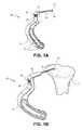
- FIG. 1Aillustrates an exemplary embodiment of a positioning instrument of the present invention
- FIG. 1Billustrates the positioning instrument of FIG. 1A in situ
- FIG. 2Aillustrates a perspective view of an exemplary insertion tool with an exemplary implantable device
- FIG. 2Billustrates an enlarged view of the tip of the insertion tool of FIG. 2A ;
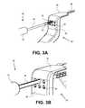
- FIGS. 3A-3Dillustrate various steps of using the insertion tool and implantable device of FIG. 2A with the positioning instrument of FIG. 1A ;
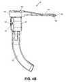
- FIG. 4Aillustrates a front view of another exemplary embodiment of a positioning instrument of the present invention
- FIG. 4Billustrates a side view of the positioning instrument of FIG. 4A ;
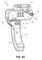
- FIG. 4Cillustrates a rear view of the positioning instrument of FIG. 4A ;
- FIG. 5illustrates a perspective view of an indicator probe of FIG. 4A ;
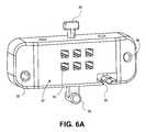
- FIG. 6Aillustrates a perspective view of an insertion gauge of the positioning instrument of FIG. 4A ;
- FIG. 6Billustrates a perspective view of another exemplary embodiment of an insertion gauge of the present invention.
- FIG. 7illustrates a perspective view of the handle of FIG. 4A ;
- FIG. 8illustrates a perspective view of another exemplary embodiment of a positioning instrument of the present invention.
- FIG. 9illustrates a perspective view of the handle of FIG. 8 ;
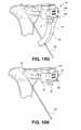
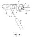
- FIGS. 10A-10Iillustrate various steps of using the positioning instrument of FIG. 4A ;
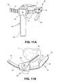
- FIG. 11Aillustrates a perspective view of yet another embodiment of a positioning instrument of the present invention in situ
- FIG. 11Billustrates a top-down view of the positioning instrument of FIG. 11A in situ
- FIG. 11Cillustrates a side view of the positioning instrument of FIG. 11A in situ
- FIG. 11Dillustrates a rear view of the positioning instrument of FIG. 11A .
- the present disclosureprovides a methodology, devices and instruments for diagnosing and treating joint pain to restore natural joint function and preserving, as much as possible, the joint's articular and cartilage surface.
- Treatments through the joint that violate the articular and cartilage surfaceoften weaken the bone and have unpredictable results.
- the embodimentsdiagnose and treat pain at its source in the subchondral region of a bone of a joint to relieve the pain.
- pain associated with joints, especially osteoarthritic jointscan be correlated to bone defects or changes at the subchondral level rather than, for example, the severity of osteoarthritic progression or defects at the articular surface level.
- bone defectssuch as bone marrow lesions, edema, fissures, fractures, hardened bone, etc. near the joint surface lead to a mechanical disadvantage and abnormal stress distribution in the periarticular bone, which may cause inflammation and generate pain.
- periarticular bonewhich may or may not be sclerotic
- the present disclosureprovides methods, devices, and systems for a subchondral procedure.
- This procedure and its associated devices, instruments, etc.are also marketed under the registered trademark name of SUBCHONDROPLASTYTM.
- SUBCHONDROPLASTYTM procedureis a response to a desire for an alternative to patients facing partial or total knee replacement.
- the SUBCHONDROPLASTYTM or SCPTM techniqueis intended to both strengthen the bone and stimulate the bone.
- SCPTMbone fractures or non-unions are stabilized, integrated or healed, which results in reduction of a bone defect, such as a bone marrow lesion or edema.
- SCPTMrestores or alters the distribution of forces in a joint to thereby relieve pain.
- SCPTMcan be performed arthroscopically or percutaneously to treat pain by stabilizing chronic stress fracture, resolving any chronic bone marrow lesion or edema, and preserving, as much as possible, the articular surfaces of the joint.
- SUBCHONDROPLASTYTMgenerally comprises evaluating a joint, for example, by taking an image of the joint, detecting the presence of one or more subchondral defects, diagnosing which of these subchondral defects is the source of pain, and determining an extent of treatment for the subchondral defect.
- the present techniqueis particularly suited for treating chronic defects or injuries, where the patient's natural healing response has not resolved the defect. It should be noted, however, that the technique is equally applicable to treatment of defects in the subchondral region of bone where the defect is due to an acute injury or from other violations.
- the present disclosureprovides several exemplary treatment modalities for SCPTM for the different extents of treatment needed. Accordingly, a medical practitioner may elect to use the techniques and devices described herein to subchondrally treat any number of bone defects as he deems appropriate.
- detection and identification of the relevant bone marrow lesion or bone marrow edemacan be achieved by imaging, e.g., magnetic resonance imaging (MRI), X-ray, manual palpation, chemical or biological assay, and the like.
- MRImagnetic resonance imaging
- X-rayX-ray
- a T1-weighted MRIcan be used to detect sclerotic bone, for example.
- a T2-weighted MRIcan be used to detect lesions, edemas, and cysts.
- X-ray imagingmay be suitable for early-stage as well as end-stage arthritis. From the imaging, certain defects may be identified as the source of pain.
- defects that are associated with chronic injury and chronic deficit of healingare differentiated from defects that result, e.g., from diminished bone density.
- SCPTM treatmentsare appropriate for a BML or BME that may be characterized as a bone defect that is chronically unable to heal (or remodel) itself, which may cause a non-union of the bone, stress or insufficiency fractures, and perceptible pain.
- Factors consideredmay include, among other things, the nature of the defect, size of the defect, location of the defect, etc. For example, bone defects at the edge near the articular surface or periphery of a joint may be often considered eligible for treatment due to edge-loading effects as well as the likelihood of bone hardening at these locations.
- a bone defect caused by an acute injurywould generally be able to heal itself through the patient's own natural healing process.
- SCPTM treatmentscan be administered on acute stress fractures, BML or BME, or other subchondral defects, as previously mentioned.
- the SCPTM treatmentmay continue after surgery.
- the patientmay be monitored for a change in pain scores, or positive change in function.
- patientsare also checked to see when they are able to perform full weight-bearing activity and when they can return to normal activity.
- the SCPTM procedurecan be completely reversed in the event that a patient requires or desires a joint replacement or other type of procedure.
- the SCPTM treatmentmay also be performed in conjunction with other procedures, such as cartilage resurfacing, regeneration or replacement, if desired.
- the present disclosureprovides a number of treatment modalities, and associated devices, instruments and related methods of use for performing SUBCHONDROPLASTYTM. These treatment modalities may be used alone or in combination.
- the subchondral bone in the region of the bone marrow lesion or defectcan be strengthened by introduction of a hardening material, such as a bone substitute, at the site.
- a hardening materialsuch as a bone substitute
- the bone substitutemay be an injectable calcium phosphate ensconced in an optimized carrier material.
- the injected materialmay also serve as a bone stimulator that reinvigorates the desired acute bone healing activity.
- PMMApolymethylmethacrylate
- CaP cement injectionscan be made at the defect site.
- PMMA injectionmay increase the mechanical strength of the bone, allowing it to withstand greater mechanical stresses.
- CaP cement injectionmay also increase the mechanical strength of the bone, while also stimulating the localized region for bone fracture repair.
- the injectioncan be made parallel to the joint surface.
- the injectioncan be made at an angle to the joint surface.
- the injectioncan be made below a bone marrow lesion.
- the subchondral bone regioncan be stimulated to trigger or improve the body's natural healing process.
- one or more small holesmay be drilled at the region of the defect to increase stimulation (e.g., blood flow, cellular turnover, etc.) and initiate a healing response leading to bone repair.
- an osteogenic, osteoinductive, or osteoconductive agentmay be introduced to the site.
- Bone graft materialfor example, may be used to fill the hole.
- Electrical or heat stimulationmay also be employed to stimulate the healing process of a chronically injured bone.
- Chemical, biochemical and/or biological stimulationmay also be employed in SCPTM. For instance, stimulation of bone tissue in SCPTM may be enhanced via the use of cytokines and other cell signaling agents to trigger osteogenesis, chondrogenesis, and/or angiogenesis to perhaps reverse progression of osteoarthritis.
- an implantable devicemay be implanted into the subchondral bone to provide mechanical support to the damaged or affected bone region, such as where an insufficiency fracture or stress fracture has occurred.
- the implantmay help create a better load distribution in the subchondral region.
- the implantmay support tibio-femoral compressive loads.
- the implantmay mechanically integrate sclerotic bone with the surrounding healthy bone tissue.
- the implantmay be placed in cancellous bone, through sclerotic bone, or under sclerotic bone at the affected bone region.
- the implantmay also be configured as a bi-cortical bone implant.
- one side of the implantcan be anchored to the peripheral cortex to create a cantilever beam support (i.e., a portion of the implant is inserted into bone but the second end stays outside or near the outer surface of the bone).
- the implantmay be inserted using a guide wire.
- the implantmay be inserted over a guide wire.
- the implantmay be delivered through a guide instrument.
- the implantmay further be augmented with a PMMA or CaP cement injection, other biologic agent, or an osteoconductive, osteoinductive and/or osteogenic agent.
- the augmentation materialmay be introduced through the implant, around the implant, and/or apart from the implant but at the affected bone region, such as into the lower region of a bone marrow lesion or below the lesion.
- the implantmay act as a portal to inject the augmentation material into the subchondral bone region.
- the present disclosurealso provides suitable implantable fixation devices for the surgical treatment of these altered bone regions or bone defects, especially at the subchondral level.
- Applicantshave also discovered devices and instruments that can be used in combination with cements or hardening materials commonly used to repair damaged bone by their introduction into or near the site of damage, either to create a binding agent, cellular scaffold or mechanical scaffold for immobilization, regeneration or remodeling of the bone tissue.
- the embodimentsrelate to instruments, implants and associated methods for the surgical treatment of a joint, and particularly to a bone defect at that joint region.
- pain associated with osteoarthritic jointscan be correlated to bone defects at the subchondral level.
- bone defectssuch as bone marrow lesions, edemas, fissures, fractures, etc. near sclerotic tissue lead to abnormal stress distribution of the joint, which causes inflammation and generates pain.
- By altering the makeup of the sclerotic bone in relation to the surrounding regionit is possible to change the structural integrity of the damaged bone, leading to a resolution of the inflammation.
- treatment of the bone defectsin an effort to alter the structural makeup of damaged sclerotic bone leads to reduced inflammation and pain.
- the present inventionprovides suitable instruments, implants and associated methods for the surgical treatment of these bone defects, especially at the subchondral level near sclerotic bone.
- the positioning instrument 60allows controlled delivery of a device to the target site in the bone.
- the term “device”is used herein to describe generally any number of implantable devices, materials and instruments suitable for bone treatment and/or repair.
- the devicemay be an implantable device such as implant 30 as shown in FIGS. 2A and 3A .
- the devicemay also be an insertion tool 40 , a drill, an injection needle, or a catheter.
- the positioning instrument 60may be used to provide quick, easy and accurate access to a specific target site for a number of instruments or implants that can perform any variety of treatment functions at that site.
- the positioning instrument 60can include an alignment guide 62 that serves as a jig, or a box/frame for guiding a device to a specific location on the bone being treated.
- One or more device portals 64may be provided on the alignment guide 62 .
- the positioning instrument 60can also include an indicator probe 66 for visually identifying the target site.
- the indicator probe 66can include an extended arm 68 having a suitable length to access the bone to be treated.
- the extended arm 68can include a protrusion, or knob 70 , at the terminal end 72 of the extended arm 68 .
- a handle portion 74may be provided for maneuvering the positioning instrument 60 in place during surgery.
- the handle portionmay include holes 76 for receiving other tools such as pins for stabilizing the positioning instrument 60 , as will be described in more detail below.
- FIG. 2Aillustrates an exemplary embodiment of an insertion tool 40 in use with an exemplary implantable fenestrated device 30 .
- the fenestrated implantable device 30can be of the type disclosed in U.S. patent application Ser. No. 12/950,306, filed Nov. 19, 2010 and entitled “IMPLANTABLE DEVICES FOR SUBCHONDRAL TREATMENT OF JOINT PAIN,” which is hereby incorporated in its entirety by reference.
- Other exemplary implantable devicesare disclosed in co-pending and co-owned U.S. patent application Ser. No. 12/950,273, filed Nov. 19, 2010 and entitled “IMPLANTABLE DEVICES FOR SUBCHONDRAL TREATMENT OF JOINT PAIN,” and U.S. patent application Ser. No. 12/950,183, filed Nov. 19, 2010 and entitled “BONE-DERIVED IMPLANTABLE DEVICES FOR SUBCHONDRAL TREATMENT OF JOINT PAIN,” the contents of which are herein incorporated in their entirety by reference.
- Insertion tool 40may include a gripping end 42 and terminate at a device-engaging end 44 .
- the device-engaging end 44may further include a tip 48 that mates with the tool-engaging portion of the implant 30 .
- the tip 48may be threaded, and the tool-engaging portion may comprise a threaded bore, for example.
- the tip 48 and the corresponding bore or tool-engaging portion of the implant 30may be configured in any suitable complementary fashion as well known in the art, so long as the configuration provides adequate fit and release.
- the tip 48may be provided with a desired shape, while the bore may be provided with a complementary shape to receive the tip 48 in an interference fit-type fashion.
- An elongate shaft 46can extend between the gripping end 42 and the device-engaging end 44 .
- the elongate shaft 46may include a depth stop 50 to prevent overextension of the insertion tool 40 into bone tissue.
- the depth stop 50may be stationary, or it may be adjustable along the length of the shaft 46 to allow customization of the tool 40 to the patient's anatomy.
- a mechanism(not shown) may be provided to allow adjustment of the depth stop 50 at the gripping end 42 . This mechanism may be internal to the tool 40 .
- the depth stop 50may be configured as a slidable element on the shaft 46 .
- the shaft 46may be provided with tracks (not shown) on which the depth stop 50 may sit. The depth stop 50 may be manually adjusted on the tracks to the desired depth needed by the clinician.
- FIGS. 1 B and 3 A- 3 Dillustrate various steps for using the positioning instrument 60 .
- the positioning instrument 60can be positioned such that the indicator probe 66 rests on the top surface of a bone 2 .
- the bone 2may be a tibia for a knee joint repair. It is understood, however, that the bone 2 may be any other type of bone found in a joint, such as a hip, ankle or shoulder.
- Knob 70can be used to visually indicate where the bone defect resides.
- Each portal 64has a predetermined distance and spatial relationship relative to the other portals 64 , such that the clinician can determine with accuracy the depth of the portal 64 relative to the indicator probe 66 and consequently the top surface of the bone 2 .
- the portals 64serve as spatial references or orientation or location markers for the clinician.
- the alignment guide 62may include indicia to show the distance of each portal 64 below the indicator probe 66 .
- the device portals 64are configured to provide accurate and controlled delivery of a device to the target site indicated by the indicator probe 66 .
- the portals 64may be configured at any desired angle relative to the alignment guide 62 .
- the portals 64may be angularly configured to guide, or direct, the device in a parallel direction relative to the top of the bone being treated. In another embodiment, the portals 64 may be angularly configured to direct the device in a perpendicular direction relative to the top of the bone, for example.
- the positioning instrument 60may be particularly suited to enable implants 30 to be inserted parallel or at an angle (i.e., acute, perpendicular, etc.) to the top bone surface in an easy, fast and precise manner.
- FIGS. 3A and 3Billustrate how the device portals 64 can include an anti-rotation feature.
- the device portals 64may be keyed, or shaped with a specific configuration that matches with a shape configuration of the device to be inserted.
- the device portals 64may be shaped to accommodate the fins 20 of the implant 30 in a certain orientation.
- the keyed device portals 64allow the implant 30 to enter, along with the shaft 46 of the insertion tool 40 and the depth stops 50 attached thereto, and to move freely in a linear direction in and out of the portals 64 as represented in FIGS. 3C and 3D .
- the keyed device portals 64may not allow free rotation thereabout.
- the anti-rotation featureprovides a further level of control for the clinician.
- the device portalscan have removable collars around them to act as depth stops (not shown). It is contemplated that the collars can be of a snap on, snap off type. Additionally, it is contemplated that an exterior template (not shown) having a plurality of shaped holes corresponding to the device portals 64 may be applied onto the alignment guide 62 . The template would enable the clinician to alter the shape or “key” of the portals 64 as needed. Furthermore, the template may include alternate spatial arrangements to block out certain portals while allowing access of other portals.
- the positioning instrument 60may be provided as a unitary body. However, in some cases, it may be desirable to provide a less obtrusive instrument in the surgical work area.
- FIGS. 4A-4Cillustrate an exemplary embodiment of a modular positioning instrument 80 having detachable components so that less visual space is obstructed during surgery. Furthermore, in some cases not all the components are necessary or desired.
- modular positioning instrument 80may include an alignment guide 82 that serves as a jig, or a box/frame for guiding a device to a specific location on the bone being treated.
- One or more device portals 84may be provided on the alignment guide 82 .
- the alignment guide 82may include one or more tool receiving openings 86 that allow a tool to be passed through.
- the toolmay be, for example, a pin, needle or drill bit. In one instance, the tool may be a pin to secure the alignment guide 82 to bone, as will be shown and described below.
- the positioning instrument 80can also include an optional, detachable indicator probe 100 , shown in FIG. 5 , for visually identifying the target site.
- the target sitemay first be identified arthroscopically, in one example.
- the indicator probe 100can include a body 102 from which extends an arm 104 that terminates at a terminal end 106 with a protrusion or knob 108 for visually identifying the target site. It is envisioned that the probe 100 or knob 108 could be configured in any number of designs, so long as they are suited to reach the bone from outside the incision site and identify defects, such as for example single point or multiple point protrusion, or the probe 100 and/or knob 108 could even be configured similar to a guidewire. Additionally, the terminal end 106 , indicator probe 100 or any part thereof could include a radiopaque marker for identification during use with x-rays or a C-arm.
- the body 102may further include a bore 110 for receiving a probe-attachment tab 88 , as shown in FIGS. 6A and 6B .
- a probe-attachment tab 88for receiving a probe-attachment tab 88 .
- the indicator probe 100may have a snap-fitted connection to the probe-attachment tab 88 .
- indicator probe 100may be configured to be angularly adjustable relative to the alignment guide 82 .
- a mechanismmay be provided to allow the indicator probe 100 to rotate about the alignment guide 82 , thereby enabling more flexibility for the clinician to operate the instrument 80 .
- a detachable inferior guide portion 120may also optionally be provided with the positioning instrument 80 .
- the inferior guide portion 120may include one or more tool receiving holes 122 for receiving a tool.
- the toolmay be, for example, a pin, needle or drill bit.
- the toolmay be a drill to drill a hole in the bone, as will be shown and described below.
- the inferior guide portion 120offers a distal, or inferior approach guide, for targeting the lower area of the target site or other tissue area from different angular approaches through tool-receiving holes 122 .
- the inferior guide portion 120can serve as a handle portion of the instrument 80 for manipulating the positioning instrument 80 during use.
- a notched region 124 of the inferior guide portion 120may be provided to secure the inferior guide portion 120 to the alignment guide 82 .
- the alignment guide 82may include a handle-attachment tab 90 that is configured to engage the notched region 124 of the inferior guide portion 120 .
- Any known mechanism for attaching the inferior guide portion 120 to the handle-attachment tab 90can be employed, so long as the mechanism allows quick and easy detachment, without disturbing any other components of the instrument 80 or tools that may have been employed during its use.
- the alignment guide 82may include a notched region 92 configured to receive a spring ball detent or mating spring loaded mechanism to create a “snap” fit to hold the alignment guide 82 in place.
- the notched region 92is optional, as an embodiment of an alignment guide without the notched region 92 is illustrated in FIG. 6B .
- the notched region 92may be replaced by a screw, cam lock, or any other mechanism to hold the two components (i.e., the inferior guide portion 120 to the alignment guide 82 ) together in a simple manner but still allow easy connection and disconnection of the components without disturbing other components of the instrument 80 or other tools that may have been employed during its use.
- FIG. 7illustrates one exemplary embodiment of the inferior guide portion 120 wherein the main body is curved for easy gripping.
- FIG. 8illustrates another exemplary embodiment of a positioning instrument 180 whereby a straight handle portion 130 is attached to the alignment guide 82 and indicator probe 100 previously described.
- the straight handle portion 130may include a notched region 134 , similar to notched region 124 of curved inferior guide portion 120 , for receiving the handle-attachment tab 90 of gauge plate 82 .
- any known mechanism for attaching the handle portion 130 to the handle-attachment tab 90can be employed, so long as the mechanism allows quick and easy detachment, without disturbing any other components of the instrument 180 or tools that may have been employed during its use.
- the straight handle portion 130does not have tool receiving holes, though it is contemplated that such holes could easily be provided if desired.
- FIGS. 10A-10Iillustrate an exemplary method of using the modular positioning instrument 80 with the insertion tool 40 and implant 30 of the present disclosure to repair a bone defect in a tibia 2 having a bone marrow lesion in the subchondral bone.
- the methodprovides a minimally invasive, tissue sparing technique for accessing, identifying and treating the target site.
- a surgical incisionmay be made to access the bone to be treated.
- the target sitemay be a bone marrow lesion in the subchondral bone.
- the cartilage above the target siteis also damaged, providing a clear visual cue to the clinician of where the defect resides.
- a clinicianmay identify a target site for treatment, use a template to mark the site, and extrapolate that template over a C-arm image available in the operating room in a set view. Once identified, either arthroscopically or through imaging technology, the clinician may then target the indicator probe 100 of the modular positioning instrument 80 to the target site, placing the indicator knob 108 of the positioning instrument 80 on top of the tibial bone 2 and over the target site.
- the cliniciancan secure the positioning instrument 80 in place by inserting superior pins 200 through the tool openings 86 of the alignment guide 82 , as illustrated in FIG. 10B .
- the superior pins 200may be oriented in a converging or diverging pattern, depending on the clinician's needs. In order to prevent overextension, it is possible to provide the pins 200 with a collar, indicia such as colored bands or measurement marks, or a shoulder section, that would enable the clinician to know how far to insert the pins.
- the clinicianmay then elect to insert a drill 210 through one of the device portals 84 and drill a hole or cavity 300 proximate to the target site, or bone marrow lesion in this example.
- the drill 210is removed and then the insertion tool 40 with the implant 30 attached may be placed through the same device portal 84 .
- the implant 30may be inserted into the cavity 300 , as shown in FIG. 10E .
- the positioning instrument 80is particularly suited to guide, or direct, the implant 30 to be inserted parallel to the top of the bone 2 , as illustrated.
- the cavity 300may be either larger in diameter than the outer diameter of the implant 30 , or it may be nearly the same diameter, depending on whether the clinician desires space around the implant 30 for a biologic material, bone cement or other bone void filler. Where the cavity is nearly the same diameter as the outer diameter of the implant 30 , the fins 20 may be configured to allow some space for the biologic material, cement or filler to reside around the implant 30 . In other embodiments, the fins 20 may be press-fit into bone to create an interference fit with the cavity 300 .
- the insertion tool 40may be removed.
- the clinicianmay elect to inject a bone cement, such as calcium phosphate, for instance, into the implant 30 .
- a bone cementsuch as calcium phosphate
- an injection catheter 220 filled with bone cementmay be placed through the same device portal 84 to the implant 30 , as shown in FIG. 10F .
- the bone cementmay then be injected through the implant 30 , and the injection catheter 220 removed from the alignment guide 82 .
- an inferior pin 202may be placed through one of the tool openings 122 of the inferior guide portion 120 .
- the inferior guide portion 120may then be removed by undoing the connection between the notched region 124 and the handle-attachment tab 90 , and sliding the inferior guide portion 120 down the inferior pin 202 .
- What remainsis the alignment guide 82 and the attached indicator probe 100 , still secured in place by the pair of pins 200 extending through tool openings 86 , as shown in FIG. 10H . If needed, the implant 30 may need to be sealed to prevent cement leakage.
- inferior guide portion 120 and the straight handle portion 130are interchangeable, it is possible to use both components in a step-wise fashion. For instance, it is envisioned that one could first use the straight handle portion 130 to manipulate the positioning instrument 180 in place, then after the alignment guide 82 has been secured with the pins 200 , the straight handle portion 130 can be removed and the inferior guide portion 120 attached to allow targeting of tissue inferior to the target site by different angular approaches through tool-receiving holes 122 .
- the injection catheter 220 or an injection needlemay be slid over the inferior pin 202 , and bone cement may be optionally injected below the bone defect, or bone marrow lesion, in this example and as shown in FIG. 10I . Lastly, all instrumentation can be removed and the surgical incision site closed up.
- the device portals 84play a crucial role in the clinician's ability to easily and precisely access the target site, particularly when the target site is in a very limited region of the bone such as subchondral bone.
- the device portals 84function as spatial references, orientation markers or location markers, and allow the clinician to perform multiple functions in a precise, minimally invasive, tissue sparing manner in less time.
- the method just described and illustratedemploys an implant 30 at the target site to treat the bone marrow lesion that is the bone defect in question
- proceduresmay be administered using the positioning instrument 80 provided.
- any of the specific procedural steps of FIGS. 10A-10Imay be performed either alone or in combination in varying order.
- the step of cavity creationmay be the only function the clinician elects to perform.
- the step of cavity creationmay be combined with the step of bone cement injection, without the step of inserting an implant into the cavity, though still using the principles of the present disclosure and positioning instrument 80 provided.
- FIGS. 11A-11Dillustrate an exemplary embodiment of a positioning instrument holder 140 that allows for angular orientation of the positioning instrument 80 of the present disclosure.
- probe 100 visualizationis achieved through a general portal where it is desirable to treat a local area specific to the defect being identified using a percutaneous approach near the defect.
- positioning instrument holder 140may include a central body 142 having a slot 144 for receiving a rail, or track belt, 150 .
- the track belt 150may be curved and include a plurality of detents 152 .
- the track belt 150can include a slotted channel 156 extending into each end 154 for receiving side tabs 94 provided on the alignment guide 82 .
- the side tabs 94may be notched so as to allow the slotted channel 156 to catch, thereby providing an easy catch and release mechanism for securing the alignment guide 82 to the track belt 150 .
- the mechanismcan be, for example, a slip fit or an interference fit. If desired, a spring button release may also be employed.
- the central body 142 of the positioning instrument holder 140may extend into a handle 146 , and further include a catch and release mechanism 148 , such as a spring button release, for releasable hold of the detents 152 on the track belt 150 .
- the plurality of detentsprovides incremental angular positioning of the alignment guide 82 relative to the track belt 150 .
- the indicator probe 100may be adjustably mounted to the central body 142 of the positioning instrument holder 140 . This allows the indicator probe 100 to be indexed to a left or right approach to the target site.
- the indicator probe 100is shown to be angularly adjustable relative to the central body 142 in the illustrations, it is understood that the indicator probe may be stationary and rigidly fixed at a right angle relative to the central body if desired.
Landscapes
- Health & Medical Sciences (AREA)
- Life Sciences & Earth Sciences (AREA)
- Surgery (AREA)
- Orthopedic Medicine & Surgery (AREA)
- Engineering & Computer Science (AREA)
- General Health & Medical Sciences (AREA)
- Veterinary Medicine (AREA)
- Public Health (AREA)
- Nuclear Medicine, Radiotherapy & Molecular Imaging (AREA)
- Biomedical Technology (AREA)
- Heart & Thoracic Surgery (AREA)
- Medical Informatics (AREA)
- Molecular Biology (AREA)
- Animal Behavior & Ethology (AREA)
- Dentistry (AREA)
- Oral & Maxillofacial Surgery (AREA)
- Transplantation (AREA)
- Surgical Instruments (AREA)
- Prostheses (AREA)
Abstract
Description
Claims (22)
Priority Applications (9)
| Application Number | Priority Date | Filing Date | Title |
|---|---|---|---|
| US12/950,355US8951261B2 (en) | 2009-11-20 | 2010-11-19 | Subchondral treatment of joint pain |
| US12/950,230US9259257B2 (en) | 2009-11-20 | 2010-11-19 | Instruments for targeting a joint defect |
| PCT/US2010/057471WO2011063257A1 (en) | 2009-11-20 | 2010-11-19 | Instruments for targeting a joint defect |
| AU2010321812AAU2010321812B2 (en) | 2009-11-20 | 2010-11-19 | Instruments for targeting a joint defect |
| CN2010800525809ACN102740789A (en) | 2009-11-20 | 2010-11-19 | Instruments for targeting a joint defect |
| EP10832277.7AEP2501314B1 (en) | 2009-11-20 | 2010-11-19 | Instruments for targeting a joint defect |
| KR1020127015880AKR20120112470A (en) | 2009-11-20 | 2010-11-19 | Instruments for targeting a joint defect |
| JP2012540097AJP2013511353A (en) | 2009-11-20 | 2010-11-19 | Equipment for targeting joint abnormalities |
| US14/617,058US9717544B2 (en) | 2009-11-20 | 2015-02-09 | Subchondral treatment of joint pain |
Applications Claiming Priority (4)
| Application Number | Priority Date | Filing Date | Title |
|---|---|---|---|
| US26317009P | 2009-11-20 | 2009-11-20 | |
| US29297910P | 2010-01-07 | 2010-01-07 | |
| US12/950,355US8951261B2 (en) | 2009-11-20 | 2010-11-19 | Subchondral treatment of joint pain |
| US12/950,230US9259257B2 (en) | 2009-11-20 | 2010-11-19 | Instruments for targeting a joint defect |
Publications (2)
| Publication Number | Publication Date |
|---|---|
| US20110125160A1 US20110125160A1 (en) | 2011-05-26 |
| US9259257B2true US9259257B2 (en) | 2016-02-16 |
Family
ID=44060033
Family Applications (1)
| Application Number | Title | Priority Date | Filing Date |
|---|---|---|---|
| US12/950,230Active2031-01-08US9259257B2 (en) | 2009-11-20 | 2010-11-19 | Instruments for targeting a joint defect |
Country Status (7)
| Country | Link |
|---|---|
| US (1) | US9259257B2 (en) |
| EP (1) | EP2501314B1 (en) |
| JP (1) | JP2013511353A (en) |
| KR (1) | KR20120112470A (en) |
| CN (1) | CN102740789A (en) |
| AU (1) | AU2010321812B2 (en) |
| WO (1) | WO2011063257A1 (en) |
Cited By (13)
| Publication number | Priority date | Publication date | Assignee | Title |
|---|---|---|---|---|
| US9386996B2 (en) | 2009-11-20 | 2016-07-12 | Zimmer Knee Creations, Inc. | Navigation and positioning instruments for joint repair |
| US9717544B2 (en) | 2009-11-20 | 2017-08-01 | Zimmer Knee Creations, Inc. | Subchondral treatment of joint pain |
| US9730744B2 (en) | 2009-11-20 | 2017-08-15 | Zimmer Knee Creations, Inc. | Method for treating joint pain and associated instruments |
| US9925010B2 (en) | 2016-02-19 | 2018-03-27 | Rajiv D. Pandya | System and technique for accessing extra articular lesions or abnormalities or intra osseous lesions or bone marrow lesions |
| US10064633B2 (en) | 2016-02-19 | 2018-09-04 | Rajiv D. Pandya | System and technique for accessing extra articular lesions or abnormalities or intra osseous lesions or bone marrow lesions |
| US20180368924A1 (en)* | 2016-02-19 | 2018-12-27 | Rajiv D. Pandya | System And Technique For Accessing Extra Articular Lesions Or Abnormalities Or Intra Osseous Lesions Or Bone Marrow Lesions |
| US10357314B2 (en) | 2015-07-08 | 2019-07-23 | Stryker European Holdings I, Llc | Instrumentation and method for repair of a bone fracture |
| US11172940B2 (en) | 2011-12-30 | 2021-11-16 | Howmedica Osteonics Corp. | Systems and methods for preparing bone voids to receive a prosthesis |
| US11172941B2 (en) | 2013-03-13 | 2021-11-16 | Howmedica Osteonics Corp. | Void filling joint prosthesis and associated instruments |
| US11173034B2 (en)* | 2015-01-12 | 2021-11-16 | Howmedica Osteonics Corp. | Bone void forming apparatus |
| US11376079B2 (en) | 2016-02-19 | 2022-07-05 | Rajiv D. Pandya | System and technique for accessing extra articular lesions or abnormalities or intra osseous lesions or bone marrow lesions |
| US11419684B2 (en) | 2016-02-19 | 2022-08-23 | Rajiv D. Pandya | System and technique for accessing extra articular lesions or abnormalities or intra osseous lesions or bone marrow lesions |
| US11963688B2 (en) | 2021-11-20 | 2024-04-23 | Panorthopaedics, Inc. | Device adapted for lateral engagement of an elongated member |
Families Citing this family (35)
| Publication number | Priority date | Publication date | Assignee | Title |
|---|---|---|---|---|
| US8864768B2 (en) | 2009-11-20 | 2014-10-21 | Zimmer Knee Creations, Inc. | Coordinate mapping system for joint treatment |
| JP2013511356A (en) | 2009-11-20 | 2013-04-04 | ニー・クリエイションズ・リミテッド・ライアビリティ・カンパニー | Device for variable angle approach to joints |
| WO2011063240A1 (en) | 2009-11-20 | 2011-05-26 | Knee Creations, Llc | Implantable devices for subchondral treatment of joint pain |
| WO2011063260A1 (en) | 2009-11-20 | 2011-05-26 | Knee Creations, Llc | Bone-derived implantable devices for subchondral treatment of joint pain |
| US9259257B2 (en) | 2009-11-20 | 2016-02-16 | Zimmer Knee Creations, Inc. | Instruments for targeting a joint defect |
| US8652148B2 (en)* | 2010-02-25 | 2014-02-18 | Zimmer, Inc. | Tracked cartilage repair system |
| US9119644B2 (en)* | 2010-08-21 | 2015-09-01 | New York Society For The Ruptured And Crippled Maintaining The Hospital For Special Surgery | Instruments for use in femoroacetabular impingement procedures |
| US10603049B2 (en) | 2011-09-02 | 2020-03-31 | Episurf Ip-Management Ab | Implant specific drill bit in surgical kit for cartilage repair |
| EP2564792A1 (en) | 2011-09-02 | 2013-03-06 | Episurf Medical AB | Modular surgical kit for cartilage repair |
| US11000387B2 (en) | 2011-09-02 | 2021-05-11 | Episurf Ip-Management Ab | Implant for cartilage repair |
| EP2765925A1 (en)* | 2011-10-11 | 2014-08-20 | Zimmer Knee Creations, Inc. | Methods and instruments for subchondral treatment of osteoarthritis in a small joint |
| US9629646B2 (en) | 2012-07-11 | 2017-04-25 | Jens Kather | Curved burr surgical instrument |
| CN105377128B (en) | 2013-03-15 | 2019-02-22 | 9234438加拿大股份有限公司 | Electrosurgical mapping tools and methods |
| US9872705B2 (en) | 2013-10-07 | 2018-01-23 | Regentis Biomaterials Ltd. | Treatment of cavities in a human body |
| US9895519B2 (en) | 2013-10-07 | 2018-02-20 | Regentis Biomaterials Ltd. | Treatment of cavities in a human body |
| WO2016004991A1 (en) | 2014-07-09 | 2016-01-14 | Episurf Ip-Management Ab | Customized implant for cartilage repair and corresponding method of design |
| US20170172744A1 (en) | 2014-07-09 | 2017-06-22 | Episurf Ip-Management Ab | Surgical joint implant and a bone-mountable rig |
| CA3100061A1 (en) | 2015-09-02 | 2017-03-09 | Wright Medical Technology, Inc. | Chevron osteotomy tools and methods |
| US10918412B2 (en)* | 2015-12-18 | 2021-02-16 | Boston Scientific Scimed, Inc. | Surgical guidance devices, methods, and systems |
| CN108697472B (en) | 2016-02-19 | 2021-06-25 | 桑尼布鲁克研究所 | Positioning and Alignment Instruments for Introducing Surgical Devices into Bone |
| CN107961068A (en)* | 2016-10-20 | 2018-04-27 | 练克俭 | A kind of parallel angle guider used in internal fixation of fracture |
| USD877903S1 (en)* | 2017-06-16 | 2020-03-10 | Karl Storz Se & Co. Kg | Target apparatus |
| BR112019021679A2 (en)* | 2017-08-04 | 2020-05-12 | Wright Medical Technology, Inc. | SCREW DIRECTION GUIDE SYSTEM AND METHOD |
| CN108553178A (en)* | 2018-04-27 | 2018-09-21 | 吴飞 | A kind of operation on joint fixing device |
| US11980507B2 (en) | 2018-05-02 | 2024-05-14 | Augmedics Ltd. | Registration of a fiducial marker for an augmented reality system |
| CN109077794B (en)* | 2018-08-09 | 2020-07-31 | 河南科技大学第一附属医院 | Orthopedics is with fixed type kirschner wire of coplanar pre-fixing guider |
| JP7481260B2 (en)* | 2018-09-21 | 2024-05-10 | オリンパステルモバイオマテリアル株式会社 | Bone surgery instruments |
| IT201900012318A1 (en)* | 2019-07-18 | 2021-01-18 | Smith & Nephew Inc | GUIDE GROUP FOR CORACOID DRILL AND RELATIVE METHODS OF USE |
| US11980506B2 (en)* | 2019-07-29 | 2024-05-14 | Augmedics Ltd. | Fiducial marker |
| US11382712B2 (en) | 2019-12-22 | 2022-07-12 | Augmedics Ltd. | Mirroring in image guided surgery |
| US12343045B2 (en) | 2020-03-30 | 2025-07-01 | Wright Medical Technology, Inc. | Targeting guide and associated method |
| IT202000032936A1 (en)* | 2020-12-31 | 2022-07-01 | Alessandro Russo | SUPPORT RETICULAR STRUCTURE |
| WO2023021448A1 (en) | 2021-08-18 | 2023-02-23 | Augmedics Ltd. | Augmented-reality surgical system using depth sensing |
| EP4511809A1 (en) | 2022-04-21 | 2025-02-26 | Augmedics Ltd. | Systems and methods for medical image visualization |
| US20240390031A1 (en)* | 2023-05-25 | 2024-11-28 | Amplify Surgical, Inc. | Multi-portal surgical tools and systems |
Citations (210)
| Publication number | Priority date | Publication date | Assignee | Title |
|---|---|---|---|---|
| US2697433A (en)* | 1951-12-04 | 1954-12-21 | Max A Zehnder | Device for accurately positioning and guiding guide wires used in the nailing of thefemoral neck |
| US3913187A (en)* | 1973-10-18 | 1975-10-21 | Nifco Inc | Squeeze-action clamp |
| US3988783A (en) | 1976-01-21 | 1976-11-02 | Richards Manufacturing Company, Inc. | Prosthetic collateral ligament |
| US4037592A (en) | 1976-05-04 | 1977-07-26 | Kronner Richard F | Guide pin locating tool and method |
| US4108165A (en)* | 1977-06-20 | 1978-08-22 | Krautkramer-Branson, Incorporated | Transducer probe for pulse-echo ultrasonic exploration |
| US4360012A (en)* | 1980-02-19 | 1982-11-23 | National Research Development Corporation | External fixation devices for orthopaedic fractures |
| US4653487A (en) | 1986-01-29 | 1987-03-31 | Maale Gerhard E | Intramedullary rod assembly for cement injection system |
| US4781182A (en)* | 1986-10-03 | 1988-11-01 | Purnell Mark L | Apparatus and method for use in performing a surgical operation |
| US4815454A (en) | 1987-11-16 | 1989-03-28 | Dozier Jr John K | Apparatus and method for injecting bone cement |
| US4883048A (en)* | 1986-10-03 | 1989-11-28 | Purnell Mark L | Apparatus and method for use in performing a surgical operation |
| US4911153A (en) | 1988-02-04 | 1990-03-27 | Biomet, Inc. | Orthopedic surgical instrument |
| US4920958A (en) | 1986-11-05 | 1990-05-01 | Minnesota Mining And Manufacturing Company | Drill guide assembly |
| US4964861A (en) | 1988-12-22 | 1990-10-23 | John M. Agee | Instrumentation for implanting prosthetic devices |
| US5098383A (en) | 1990-02-08 | 1992-03-24 | Artifax Ltd. | Device for orienting appliances, prostheses, and instrumentation in medical procedures and methods of making same |
| US5163940A (en)* | 1991-03-04 | 1992-11-17 | American Cyanamid Company | Surgical drill guide for tibia |
| US5178164A (en) | 1987-11-10 | 1993-01-12 | Allen George S | Method for implanting a fiducial implant into a patient |
| US5247934A (en) | 1991-08-09 | 1993-09-28 | Trustees Of The University Of Pennsylvania | Method and apparatus for diagnosing osteoporosis with MR imaging |
| US5298254A (en) | 1989-09-21 | 1994-03-29 | Osteotech, Inc. | Shaped, swollen demineralized bone and its use in bone repair |
| US5324295A (en)* | 1992-04-24 | 1994-06-28 | Shapiro Michael R | Drill guide for surgical pins |
| US5342363A (en) | 1992-11-30 | 1994-08-30 | Wright Medical Technology, Inc. | Medical instrument and procedure |
| US5370646A (en) | 1992-11-16 | 1994-12-06 | Reese; H. William | Bone clamp and installation tool |
| US5458602A (en)* | 1994-01-11 | 1995-10-17 | Mitek Surgical Products, Inc. | Surgical drill guide |
| US5514137A (en) | 1993-12-06 | 1996-05-07 | Coutts; Richard D. | Fixation of orthopedic devices |
| US5556429A (en) | 1994-05-06 | 1996-09-17 | Advanced Bio Surfaces, Inc. | Joint resurfacing system |
| US5595193A (en) | 1993-02-12 | 1997-01-21 | Walus; Richard L. | Tool for implanting a fiducial marker |
| US5609636A (en) | 1994-05-23 | 1997-03-11 | Spine-Tech, Inc. | Spinal implant |
| US5618549A (en) | 1993-05-13 | 1997-04-08 | Inoteb | Use of particles of a biocompatible and bioabsorbable calcium salt as active ingredient in the preparation of a medicinal product intended for the local treatment of bone demineralization diseases |
| US5681320A (en) | 1991-12-13 | 1997-10-28 | Mcguire; David A. | Bone-cutting guide |
| US5741266A (en)* | 1996-09-19 | 1998-04-21 | Biomet, Inc. | Pin placement guide and method of making a bone entry hole for implantation of an intramedullary nail |
| US5743916A (en)* | 1990-07-13 | 1998-04-28 | Human Factors Industrial Design, Inc. | Drill guide with removable ferrules |
| US5755809A (en) | 1995-06-07 | 1998-05-26 | Implex Corporation | Femoral head core channel filling prothesis |
| US5766221A (en) | 1991-12-03 | 1998-06-16 | Boston Scientific Technology, Inc. | Bone anchor implantation device |
| US5827289A (en) | 1994-01-26 | 1998-10-27 | Reiley; Mark A. | Inflatable device for use in surgical protocols relating to treatment of fractured or diseased bones |
| US5868749A (en) | 1996-04-05 | 1999-02-09 | Reed; Thomas M. | Fixation devices |
| US5888220A (en) | 1994-05-06 | 1999-03-30 | Advanced Bio Surfaces, Inc. | Articulating joint repair |
| US5891150A (en)* | 1996-12-04 | 1999-04-06 | Chan; Kwan-Ho | Apparatus and method for fixing a ligament in a bone tunnel |
| US5928239A (en) | 1998-03-16 | 1999-07-27 | University Of Washington | Percutaneous surgical cavitation device and method |
| US5968050A (en)* | 1997-12-05 | 1999-10-19 | Smith & Nephew, Inc. | Positioning a tibial tunnel |
| US5972015A (en) | 1997-08-15 | 1999-10-26 | Kyphon Inc. | Expandable, asymetric structures for deployment in interior body regions |
| US6010502A (en) | 1995-12-19 | 2000-01-04 | Spine-Tech, Inc. | Method and apparatus for conjoining bone bodies |
| US6036696A (en) | 1997-12-19 | 2000-03-14 | Stryker Technologies Corporation | Guide-pin placement device and method of use |
| US6039742A (en) | 1996-05-04 | 2000-03-21 | Synthes (U.S.A.) | Alignment device for locking the base part of intramedullary nails |
| US6048346A (en) | 1997-08-13 | 2000-04-11 | Kyphon Inc. | Systems and methods for injecting flowable materials into bones |
| US6066154A (en) | 1994-01-26 | 2000-05-23 | Kyphon Inc. | Inflatable device for use in surgical protocol relating to fixation of bone |
| US6111164A (en) | 1996-06-21 | 2000-08-29 | Musculoskeletal Transplant Foundation | Bone graft insert |
| US6110211A (en) | 1998-05-01 | 2000-08-29 | Weiss; James M. | Hip replacement methods and apparatus |
| US6120511A (en) | 1997-11-18 | 2000-09-19 | Chan; Kwan-Ho | Drill guide assembly and method for producing a bone tunnel |
| US6140452A (en) | 1994-05-06 | 2000-10-31 | Advanced Bio Surfaces, Inc. | Biomaterial for in situ tissue repair |
| US6143030A (en) | 1999-03-26 | 2000-11-07 | Bristol-Myers Squibb Co. | Impaction allograft form and method of orthopaedic surgery using same |
| US6162225A (en) | 1998-10-26 | 2000-12-19 | Musculoskeletal Transplant Foundation | Allograft bone fixation screw method and apparatus |
| US6241734B1 (en) | 1998-08-14 | 2001-06-05 | Kyphon, Inc. | Systems and methods for placing materials into bone |
| US6248131B1 (en) | 1994-05-06 | 2001-06-19 | Advanced Bio Surfaces, Inc. | Articulating joint repair |
| US6248110B1 (en) | 1994-01-26 | 2001-06-19 | Kyphon, Inc. | Systems and methods for treating fractured or diseased bone using expandable bodies |
| US6254605B1 (en) | 1990-07-16 | 2001-07-03 | Stephen M. Howell | Tibial guide |
| US6267770B1 (en) | 1997-05-15 | 2001-07-31 | Regents Of The University Of Minnesota | Remote actuation of trajectory guide |
| US6270528B1 (en) | 1998-08-06 | 2001-08-07 | Sdgi Holdings, Inc. | Composited intervertebral bone spacers |
| US6283942B1 (en)* | 1997-12-30 | 2001-09-04 | Volunteers For Medical Engineering | Needle insertion guide apparatus and method |
| US6285901B1 (en) | 1999-08-25 | 2001-09-04 | Echo Medical Systems, L.L.C. | Quantitative magnetic resonance method and apparatus for bone analysis |
| US6287313B1 (en) | 1999-11-23 | 2001-09-11 | Sdgi Holdings, Inc. | Screw delivery system and method |
| US6294187B1 (en) | 1999-02-23 | 2001-09-25 | Osteotech, Inc. | Load-bearing osteoimplant, method for its manufacture and method of repairing bone using same |
| US6306177B1 (en) | 1994-05-06 | 2001-10-23 | Advanced Bio Surfaces, Inc. | Biomaterial system for in situ tissue repair |
| US6342056B1 (en)* | 2000-02-04 | 2002-01-29 | Jean-Marc Mac-Thiong | Surgical drill guide and method for using the same |
| US20020029084A1 (en) | 1998-08-03 | 2002-03-07 | Paul David C. | Bone implants with central chambers |
| US6358251B1 (en) | 2000-03-21 | 2002-03-19 | University Of Washington | Method and apparatus for forming a cavity in soft tissue or bone |
| US6368322B1 (en) | 1999-04-02 | 2002-04-09 | Osteotech, Inc. | Surgical bone screw |
| US6395007B1 (en) | 1999-03-16 | 2002-05-28 | American Osteomedix, Inc. | Apparatus and method for fixation of osteoporotic bone |
| US20020151897A1 (en)* | 2001-03-30 | 2002-10-17 | Zirkle Lewis G. | Method and apparatus for locating and stabilizing an orthopedic implant |
| US6486232B1 (en) | 1997-04-18 | 2002-11-26 | Cambridge Scientific, Inc. | Bioerodible polymeric semi-interpenetrating network alloys for internal fixation devices and bone cements |
| US20030009235A1 (en) | 2000-07-19 | 2003-01-09 | Albert Manrique | Osteoimplant and method of making same |
| US6506785B2 (en) | 1998-05-22 | 2003-01-14 | Pfizer, Inc. | Treating or preventing the early stages of degeneration of articular cartilage or subchondral bone in mammals using carprofen and derivatives |
| US6506192B1 (en) | 1998-10-26 | 2003-01-14 | Musculoskeletal Transplant Foundation | Allograft bone fixation screw |
| US6527773B1 (en) | 1999-10-07 | 2003-03-04 | Osteotech, Inc. | Cervical dowel and insertion tool |
| US6533794B2 (en) | 2001-04-19 | 2003-03-18 | The Ohio State University | Simplified stereotactic apparatus and methods |
| US6564083B2 (en) | 2000-12-18 | 2003-05-13 | Hoffmann-La Roche Inc. | Bone marrow edema as predictive of susceptibility to developing progressive osteoarthritis |
| US20030097135A1 (en) | 2001-11-20 | 2003-05-22 | Penenberg Brad L. | Apparatus for, and method of, providing hip prosthesis implantation |
| US20030105468A1 (en) | 2001-12-04 | 2003-06-05 | Gorek Josef E. | System and method for reinforcing bone in preparation for screw implantation |
| US20030138473A1 (en) | 1999-08-13 | 2003-07-24 | Antony Koblish | Composite shaped bodies and methods for their production and use |
| US6607561B2 (en) | 2001-10-02 | 2003-08-19 | James Kevin Brannon | Biaxial core compression |
| WO2003084412A1 (en) | 2002-04-08 | 2003-10-16 | Mathys Medizinaltechnik Ag | Ligament tensioning device with cutting jig, and osteotomy method |
| US6645213B2 (en) | 1997-08-13 | 2003-11-11 | Kyphon Inc. | Systems and methods for injecting flowable materials into bones |
| US20030220651A1 (en)* | 2002-03-15 | 2003-11-27 | Stryker Trauma Gmbh | Targeting device for locking nails |
| US20030225456A1 (en) | 2000-05-01 | 2003-12-04 | Ek Steven W. | System and method for joint resurface repair |
| US20040002759A1 (en) | 2002-06-28 | 2004-01-01 | Ferree Bret A. | Fusion and arthroplasty devices configured to receive bone growth promoting substances |
| US20040010261A1 (en) | 2002-07-12 | 2004-01-15 | Hoag Stephen H. | Tool for releasably gripping an orthopedic implant |
| US6726691B2 (en) | 1998-08-14 | 2004-04-27 | Kyphon Inc. | Methods for treating fractured and/or diseased bone |
| US6730124B2 (en) | 2002-03-08 | 2004-05-04 | Musculoskeletal Transplant Foundation | Bone-tendon-bone assembly with cancellous allograft bone block |
| US20040106925A1 (en) | 2002-11-25 | 2004-06-03 | Culbert Brad S. | Soft tissue anchor and method of using same |
| US6746451B2 (en) | 2001-06-01 | 2004-06-08 | Lance M. Middleton | Tissue cavitation device and method |
| US20040127987A1 (en) | 2002-06-13 | 2004-07-01 | Evans Douglas G. | Devices and methods for treating defects in the tissue of a living being |
| US6767369B2 (en) | 2000-03-22 | 2004-07-27 | Synthes (Usa) | Plugs for filling bony defects |
| US20040167538A1 (en) | 2001-05-03 | 2004-08-26 | Synthes (U.S.A.) | Method of performing a transforaminal posterior lumbar interbody fusion procedure |
| US6827720B2 (en) | 2002-01-15 | 2004-12-07 | Alejandro Leali | System and method for treating osteonecrosis |
| US6863672B2 (en) | 1998-04-06 | 2005-03-08 | Kyphon Inc. | Structures and methods for creating cavities in interior body regions |
| US6869434B2 (en) | 2002-05-08 | 2005-03-22 | Soon C. Choi | Alignment system for bone fixation |
| US6875212B2 (en) | 2000-06-23 | 2005-04-05 | Vertelink Corporation | Curable media for implantable medical device |
| US20050075641A1 (en) | 2003-10-03 | 2005-04-07 | Linvatec Corporation | Osteotomy system |
| US20050119219A1 (en) | 2002-03-12 | 2005-06-02 | Davide Bellini | Ester derivatives of hyaluronic acid for the preparation of hydrogel materials by photocuring |
| US20050119753A1 (en) | 2000-02-22 | 2005-06-02 | Sdgi Holdings, Inc. | Anterior impacted bone graft and driver instruments |
| US6917827B2 (en) | 2000-11-17 | 2005-07-12 | Ge Medical Systems Global Technology Company, Llc | Enhanced graphic features for computer assisted surgery system |
| US6918916B2 (en)* | 2001-09-20 | 2005-07-19 | Richard Wolf Gmbh | Target apparatus |
| US20050159812A1 (en) | 2004-01-16 | 2005-07-21 | Dinger Fred B.Iii | Bone-tendon-bone implant |
| US6923813B2 (en) | 2003-09-03 | 2005-08-02 | Kyphon Inc. | Devices for creating voids in interior body regions and related methods |
| US20050177171A1 (en)* | 2002-02-13 | 2005-08-11 | Merrick Wetzler | Surgical drill guide |
| US20050182418A1 (en) | 2001-11-01 | 2005-08-18 | Boyd Lawrence M. | Devices and methods for the restoration of a spinal disc |
| WO2005079881A1 (en) | 2004-02-19 | 2005-09-01 | Interface Biotech A/S | Arthroscopic method for cell implantation in mammals |
| US20050203623A1 (en) | 2002-03-08 | 2005-09-15 | Musculoskeletal Transplant Foundation | Bone tendon bone assembly with cylindrical allograft bone block |
| US20050267584A1 (en) | 2001-05-25 | 2005-12-01 | Burdulis Albert G Jr | Patient selectable knee joint arthroplasty devices |
| US6979341B2 (en) | 1994-01-26 | 2005-12-27 | Kyphon Inc. | Expandable preformed structures for deployment in interior body regions |
| US20050288795A1 (en) | 2004-06-23 | 2005-12-29 | Bagga Charanpreet S | Shapeable bone graft substitute and instruments for delivery thereof |
| US20060052791A1 (en) | 2003-02-28 | 2006-03-09 | Aesculap Ag & Co. Kg | Surgical positioning and holding device |
| US20060064164A1 (en) | 2000-03-07 | 2006-03-23 | Thelen Sarah L | Method and apparatus for reducing femoral fractures |
| US7029477B2 (en)* | 2002-12-20 | 2006-04-18 | Zimmer Technology, Inc. | Surgical instrument and positioning method |
| US20060084986A1 (en) | 2004-09-30 | 2006-04-20 | Depuy Spine, Inc. | Instrument and method for the insertion and alignment of an intervertebral implant |
| US7063702B2 (en) | 1999-05-05 | 2006-06-20 | Sdgi Holdings, Inc. | Screws of cortical bone and method of manufacture thereof |
| US20060247642A1 (en) | 2004-11-09 | 2006-11-02 | Stone Kevin T | Tissue fixation device |
| US20060271059A1 (en)* | 2005-05-16 | 2006-11-30 | Arthrocare Corporation | Convergent tunnel guide apparatus and method |
| US7144414B2 (en) | 2000-06-27 | 2006-12-05 | Smith & Nephew, Inc. | Surgical procedures and instruments |
| US7155306B2 (en) | 2000-11-07 | 2006-12-26 | Mdg Medical, Inc. | Medication administration system |
| US7153305B2 (en) | 2001-03-08 | 2006-12-26 | Spine Wave, Inc. | Method for treating tibial plateau compression fractures |
| US7153306B2 (en) | 2000-10-25 | 2006-12-26 | Kyphon Inc. | Systems and methods for reducing fractured bone using a fracture reduction cannula |
| US7160305B2 (en) | 2003-03-07 | 2007-01-09 | Arthrex, Inc. | Retrodrill technique for insertion of autograft, allograft or synthetic osteochondral implants |
| US7192431B2 (en)* | 2000-04-28 | 2007-03-20 | Smith & Nephew, Inc. | Cartilage grafting |
| US20070100462A1 (en) | 2001-05-25 | 2007-05-03 | Conformis, Inc | Joint Arthroplasty Devices |
| US7226481B2 (en) | 2000-07-21 | 2007-06-05 | Spineology, Inc. | Expandable porous mesh bag device and methods of use for reduction, filling, fixation, and supporting of bone |
| US20070127987A1 (en) | 2003-08-27 | 2007-06-07 | Josef Altenbuchner | Movable stuffing machine for the production of silage stored on the bottom by means of a tubular film |
| US7241303B2 (en) | 1994-01-26 | 2007-07-10 | Kyphon Inc. | Devices and methods using an expandable body with internal restraint for compressing cancellous bone |
| US7250055B1 (en) | 2003-08-26 | 2007-07-31 | Biomet Manufacturing Corp. | Method and apparatus for cement delivering buttress pin |
| US7252671B2 (en) | 1998-08-14 | 2007-08-07 | Kyphon Inc. | Systems and methods for treating vertebral bodies |
| US7261716B2 (en) | 1999-12-23 | 2007-08-28 | Karl Storz Gmbh & Co. Kg | Biodegradable interference screw and tool for attaching a transplant to a bone |
| CN101048111A (en) | 2004-08-25 | 2007-10-03 | 脊骨技术公司 | Implants including one or more electrodes and associated insertion instruments |
| US20070276370A1 (en) | 2004-10-20 | 2007-11-29 | Vertiflex, Inc. | Minimally invasive tooling for delivery of interspinous spacer |
| US7313430B2 (en) | 2003-08-28 | 2007-12-25 | Medtronic Navigation, Inc. | Method and apparatus for performing stereotactic surgery |
| CN101102724A (en) | 2004-12-21 | 2008-01-09 | 史密夫和内修有限公司 | Rotary alignment femoral sizing guide |
| US20080027434A1 (en) | 2006-06-22 | 2008-01-31 | St. Francis Medical Technologies, Inc. | System and method for strengthening a spinous process |
| US20080039866A1 (en) | 2006-08-11 | 2008-02-14 | Medtronic, Inc. | Locating guide |
| US20080039857A1 (en)* | 2006-08-10 | 2008-02-14 | Stryker Trauma Gmbh | Distal targeting device |
| US20080103506A1 (en)* | 2006-10-30 | 2008-05-01 | Depuy Mitek, Inc. | Methods and devices for ligament repair |
| US7399306B2 (en) | 1999-10-19 | 2008-07-15 | Kyphon Inc. | Hand-held instruments that access interior body regions |
| US7410947B2 (en) | 1997-03-20 | 2008-08-12 | Stryker Corporation | Osteogenic devices and methods of use thereof for repair of endochondral bone and osteochondral defects |
| US20080195115A1 (en) | 2007-02-14 | 2008-08-14 | Depuy Mitek | Implement for orientating a tool, particularly useful in surgical tools for harvesting and implanting bone plugs to repair damaged bone tissue |
| US20080243127A1 (en) | 2001-05-25 | 2008-10-02 | Conformis, Inc. | Surgical Tools for Arthroplasty |
| US7448264B2 (en) | 2000-10-25 | 2008-11-11 | Osteotech, Inc. | Non-destructive method for evaluating the strength of cancellous bone |
| US20080281331A1 (en)* | 2007-02-08 | 2008-11-13 | Zimmer, Inc. | Targeting device |
| US20080288006A1 (en) | 2001-09-19 | 2008-11-20 | Brannon James K | Endoscopic Bone Debridement |
| US7458977B2 (en) | 2003-02-04 | 2008-12-02 | Zimmer Technology, Inc. | Surgical navigation instrument useful in marking anatomical structures |
| US20080306490A1 (en) | 2007-05-18 | 2008-12-11 | Ryan Cameron Lakin | Trackable diagnostic scope apparatus and methods of use |
| US7468075B2 (en) | 2001-05-25 | 2008-12-23 | Conformis, Inc. | Methods and compositions for articular repair |
| WO2008155772A1 (en) | 2007-06-21 | 2008-12-24 | Surgix Ltd. | A system for measuring the true dimensions and orientation of objects in a two dimensional image |
| US7477770B2 (en) | 2001-12-05 | 2009-01-13 | The Trustees Of The University Of Pennsylvania | Virtual bone biopsy |
| US7476226B2 (en) | 2000-09-01 | 2009-01-13 | Synthes (U.S.A.) | Tools and methods for creating cavities in bone |
| US7488348B2 (en) | 2003-05-16 | 2009-02-10 | Musculoskeletal Transplant Foundation | Cartilage allograft plug |
| US7491205B1 (en) | 1988-06-13 | 2009-02-17 | Warsaw Orthopedic, Inc. | Instrumentation for the surgical correction of human thoracic and lumbar spinal disease from the lateral aspect of the spine |
| US20090062797A1 (en)* | 2007-08-31 | 2009-03-05 | Huebner Randall J | Rod-based system for bone fixation |
| US20090069901A1 (en) | 2003-05-16 | 2009-03-12 | Katherine Gomes Truncale | Cartilage allograft plug |
| US20090093813A1 (en)* | 2007-10-04 | 2009-04-09 | Ebi, L.P. | Alignment device for locking nail |
| US7534226B2 (en) | 2005-09-26 | 2009-05-19 | M2 Group Holdings, Inc. | Dispensing fluid from an infusion pump system |
| US7545964B2 (en) | 2000-08-29 | 2009-06-09 | Imaging Therapeutics, Inc. | Methods and devices for quantitative analysis of x-ray images |
| CN101460105A (en) | 2006-05-19 | 2009-06-17 | 普瑞斯麦德股份有限公司 | Bone cutting fixture assembly with guide appendages |
| US7550007B2 (en) | 2005-10-26 | 2009-06-23 | Biomet Sports Medicine, Llc | Osteochondral allografts |
| US7550011B2 (en) | 2000-10-24 | 2009-06-23 | Warsaw Orthopedic, Inc. | Osteogenic packing device and method |
| US7556295B2 (en) | 2004-02-20 | 2009-07-07 | Fey Lamellenringe GmbH & Co., KG | Axial and radial play and angle compensation of a tolerating pipe connection |
| US7559932B2 (en) | 2004-12-06 | 2009-07-14 | Dfine, Inc. | Bone treatment systems and methods |
| US20090204158A1 (en)* | 2003-07-15 | 2009-08-13 | Spinal Generations, Llc | Method and device for delivering medicine to bone |
| US7594917B2 (en)* | 2001-03-13 | 2009-09-29 | Ethicon, Inc. | Method and apparatus for fixing a graft in a bone tunnel |
| US7608098B1 (en) | 2004-11-09 | 2009-10-27 | Biomet Sports Medicine, Llc | Bone fixation device |
| US7608097B2 (en) | 2003-04-29 | 2009-10-27 | Millennium Medical Technologies | Bone screw with fluid delivery structure |
| US20100015202A1 (en) | 2007-03-06 | 2010-01-21 | Semler Eric J | Cancellous construct with support ring for repair of osteochondral defects |
| US7682378B2 (en) | 2004-11-10 | 2010-03-23 | Dfine, Inc. | Bone treatment systems and methods for introducing an abrading structure to abrade bone |
| US20100076503A1 (en) | 2007-02-07 | 2010-03-25 | N.M.B. Medical Applications Ltd | Bone implant |
| US7713273B2 (en) | 2005-11-18 | 2010-05-11 | Carefusion 2200, Inc. | Device, system and method for delivering a curable material into bone |
| US20100145451A1 (en)* | 2008-12-04 | 2010-06-10 | Derek Dee | Joint support and subchondral support system |
| US20100160970A1 (en) | 2006-12-22 | 2010-06-24 | Sevrain Lionel C | Anchoring device for posteriorly attaching adjacent verterbrae |
| US7753963B2 (en) | 2001-02-28 | 2010-07-13 | Synthes Usa, Llc | Demineralized bone-derived implants |
| US20100179549A1 (en) | 2007-02-23 | 2010-07-15 | Zimmer, Gmbh | Implant for fracture treatment |
| US7769213B2 (en) | 2003-10-31 | 2010-08-03 | Aberdeen University Research And Innovation | Apparatus for predicting bone fracture risk |
| US7789912B2 (en) | 2004-01-08 | 2010-09-07 | Spine Wave, Inc. | Apparatus and method for injecting fluent material at a distracted tissue site |
| US7811290B2 (en) | 2006-04-26 | 2010-10-12 | Illuminoss Medical, Inc. | Apparatus and methods for reinforcing bone |
| US20100274254A1 (en)* | 2009-04-22 | 2010-10-28 | Pascal Boileau | Surgical instrumentation for fitting an osteosynthesis nail |
| US7840247B2 (en) | 2002-09-16 | 2010-11-23 | Imatx, Inc. | Methods of predicting musculoskeletal disease |
| US7837740B2 (en) | 2007-01-24 | 2010-11-23 | Musculoskeletal Transplant Foundation | Two piece cancellous construct for cartilage repair |
| US7837733B2 (en) | 2004-06-29 | 2010-11-23 | Spine Wave, Inc. | Percutaneous methods for injecting a curable biomaterial into an intervertebral space |
| US7846206B2 (en) | 2004-06-09 | 2010-12-07 | Vexim Sas | Methods and apparatuses for bone restoration |
| US7879099B2 (en) | 2005-06-03 | 2011-02-01 | Zipnick Richard I | Minimally invasive apparatus to manipulate and revitalize spinal column disc |
| US7887546B2 (en) | 2006-10-31 | 2011-02-15 | Warsaw Orthopedic, Inc. | Surgical instrument and method of use for facilitating positioning of an osteochondral plug |
| US7896885B2 (en) | 2002-12-03 | 2011-03-01 | Arthrosurface Inc. | Retrograde delivery of resurfacing devices |
| US7901408B2 (en) | 2002-12-03 | 2011-03-08 | Arthrosurface, Inc. | System and method for retrograde procedure |
| US7905924B2 (en)* | 2003-09-03 | 2011-03-15 | Ralph Richard White | Extracapsular surgical procedure |
| US7914539B2 (en) | 2004-11-09 | 2011-03-29 | Biomet Sports Medicine, Llc | Tissue fixation device |
| US7938835B2 (en) | 1998-08-14 | 2011-05-10 | Kyphon Sarl | Systems and methods for treating vertebral bodies |
| WO2011063240A1 (en) | 2009-11-20 | 2011-05-26 | Knee Creations, Llc | Implantable devices for subchondral treatment of joint pain |
| WO2011063257A1 (en) | 2009-11-20 | 2011-05-26 | Knee Creations, Llc | Instruments for targeting a joint defect |
| WO2011063279A1 (en) | 2009-11-19 | 2011-05-26 | Knee Creations, Llc | Coordinate mapping system for joint treatment |
| US20110125200A1 (en)* | 2009-11-20 | 2011-05-26 | Knee Creations, Llc | Navigation and positioning instruments for joint repair and methods of use |
| US20110125157A1 (en)* | 2009-11-20 | 2011-05-26 | Knee Creations, Llc | Subchondral treatment of joint pain |
| WO2011063250A1 (en) | 2009-11-20 | 2011-05-26 | Knee Creations, Llc | Implantable devices for subchondral treatment of joint pain |
| WO2011063267A1 (en) | 2009-11-20 | 2011-05-26 | Knee Creations, Llc | Instruments for a variable angle approach to a joint |
| US20110125272A1 (en) | 2009-11-20 | 2011-05-26 | Knee Creations, Llc | Bone-derived implantable devices for subchondral treatment of joint pain |
| US20110125156A1 (en) | 2009-11-20 | 2011-05-26 | Sharkey Peter F | Method for treating joint pain and associated instruments |
| US7985231B2 (en) | 2007-12-31 | 2011-07-26 | Kyphon Sarl | Bone fusion device and methods |
| US8029511B2 (en) | 2004-03-22 | 2011-10-04 | Disc Dynamics, Inc. | Multi-stage biomaterial injection system for spinal implants |
| US8062364B1 (en)* | 2007-04-27 | 2011-11-22 | Knee Creations, Llc | Osteoarthritis treatment and device |
| US8070753B2 (en) | 2004-12-06 | 2011-12-06 | Dfine, Inc. | Bone treatment systems and methods |
| US8092480B2 (en) | 2000-04-07 | 2012-01-10 | Kyphon Sarl | Platform cannula for guiding the expansion of expandable bodies and method of use |
| US8133226B2 (en) | 2005-07-12 | 2012-03-13 | Nanyang Technological University | Intramedullary fixation device for fractures |
| US8142462B2 (en) | 2004-05-28 | 2012-03-27 | Cavitech, Llc | Instruments and methods for reducing and stabilizing bone fractures |
| US8168692B2 (en) | 2004-04-27 | 2012-05-01 | Kyphon Sarl | Bone substitute compositions and method of use |
| US8187327B2 (en) | 2005-05-18 | 2012-05-29 | Kyphon Sarl | Selectively-expandable bone scaffold |
| EP2501342A1 (en) | 2009-11-20 | 2012-09-26 | Knee Creations, LLC | Subchondral treatment of joint pain |
| US8617176B2 (en)* | 2011-08-24 | 2013-12-31 | Depuy Mitek, Llc | Cross pinning guide devices and methods |
| US8636745B2 (en)* | 2011-03-09 | 2014-01-28 | Mutlaq Almutairi | Orthopedic surgical pin positioning device |
- 2010
- 2010-11-19USUS12/950,230patent/US9259257B2/enactiveActive
- 2010-11-19AUAU2010321812Apatent/AU2010321812B2/ennot_activeCeased
- 2010-11-19EPEP10832277.7Apatent/EP2501314B1/enactiveActive
- 2010-11-19JPJP2012540097Apatent/JP2013511353A/enactivePending
- 2010-11-19KRKR1020127015880Apatent/KR20120112470A/ennot_activeWithdrawn
- 2010-11-19WOPCT/US2010/057471patent/WO2011063257A1/enactiveApplication Filing
- 2010-11-19CNCN2010800525809Apatent/CN102740789A/enactivePending
Patent Citations (275)
| Publication number | Priority date | Publication date | Assignee | Title |
|---|---|---|---|---|
| US2697433A (en)* | 1951-12-04 | 1954-12-21 | Max A Zehnder | Device for accurately positioning and guiding guide wires used in the nailing of thefemoral neck |
| US3913187A (en)* | 1973-10-18 | 1975-10-21 | Nifco Inc | Squeeze-action clamp |
| US3988783A (en) | 1976-01-21 | 1976-11-02 | Richards Manufacturing Company, Inc. | Prosthetic collateral ligament |
| US4037592A (en) | 1976-05-04 | 1977-07-26 | Kronner Richard F | Guide pin locating tool and method |
| US4108165A (en)* | 1977-06-20 | 1978-08-22 | Krautkramer-Branson, Incorporated | Transducer probe for pulse-echo ultrasonic exploration |
| US4360012A (en)* | 1980-02-19 | 1982-11-23 | National Research Development Corporation | External fixation devices for orthopaedic fractures |
| US4653487A (en) | 1986-01-29 | 1987-03-31 | Maale Gerhard E | Intramedullary rod assembly for cement injection system |
| US4781182A (en)* | 1986-10-03 | 1988-11-01 | Purnell Mark L | Apparatus and method for use in performing a surgical operation |
| US4883048A (en)* | 1986-10-03 | 1989-11-28 | Purnell Mark L | Apparatus and method for use in performing a surgical operation |
| US4920958A (en) | 1986-11-05 | 1990-05-01 | Minnesota Mining And Manufacturing Company | Drill guide assembly |
| US5178164A (en) | 1987-11-10 | 1993-01-12 | Allen George S | Method for implanting a fiducial implant into a patient |
| US4815454A (en) | 1987-11-16 | 1989-03-28 | Dozier Jr John K | Apparatus and method for injecting bone cement |
| US4911153A (en) | 1988-02-04 | 1990-03-27 | Biomet, Inc. | Orthopedic surgical instrument |
| US7491205B1 (en) | 1988-06-13 | 2009-02-17 | Warsaw Orthopedic, Inc. | Instrumentation for the surgical correction of human thoracic and lumbar spinal disease from the lateral aspect of the spine |
| US4964861A (en) | 1988-12-22 | 1990-10-23 | John M. Agee | Instrumentation for implanting prosthetic devices |
| US5439684A (en) | 1989-09-21 | 1995-08-08 | Osteotech, Inc. | Shaped, swollen demineralized bone and its use in bone repair |
| US5298254A (en) | 1989-09-21 | 1994-03-29 | Osteotech, Inc. | Shaped, swollen demineralized bone and its use in bone repair |
| US5098383A (en) | 1990-02-08 | 1992-03-24 | Artifax Ltd. | Device for orienting appliances, prostheses, and instrumentation in medical procedures and methods of making same |
| US5743916A (en)* | 1990-07-13 | 1998-04-28 | Human Factors Industrial Design, Inc. | Drill guide with removable ferrules |
| US6254605B1 (en) | 1990-07-16 | 2001-07-03 | Stephen M. Howell | Tibial guide |
| US5163940A (en)* | 1991-03-04 | 1992-11-17 | American Cyanamid Company | Surgical drill guide for tibia |
| US5247934A (en) | 1991-08-09 | 1993-09-28 | Trustees Of The University Of Pennsylvania | Method and apparatus for diagnosing osteoporosis with MR imaging |
| US5766221A (en) | 1991-12-03 | 1998-06-16 | Boston Scientific Technology, Inc. | Bone anchor implantation device |
| US5681320A (en) | 1991-12-13 | 1997-10-28 | Mcguire; David A. | Bone-cutting guide |
| US5324295A (en)* | 1992-04-24 | 1994-06-28 | Shapiro Michael R | Drill guide for surgical pins |
| US5370646A (en) | 1992-11-16 | 1994-12-06 | Reese; H. William | Bone clamp and installation tool |
| US5342363A (en) | 1992-11-30 | 1994-08-30 | Wright Medical Technology, Inc. | Medical instrument and procedure |
| US5595193A (en) | 1993-02-12 | 1997-01-21 | Walus; Richard L. | Tool for implanting a fiducial marker |
| US5618549A (en) | 1993-05-13 | 1997-04-08 | Inoteb | Use of particles of a biocompatible and bioabsorbable calcium salt as active ingredient in the preparation of a medicinal product intended for the local treatment of bone demineralization diseases |
| US5514137A (en) | 1993-12-06 | 1996-05-07 | Coutts; Richard D. | Fixation of orthopedic devices |
| US5458602A (en)* | 1994-01-11 | 1995-10-17 | Mitek Surgical Products, Inc. | Surgical drill guide |
| US6235043B1 (en) | 1994-01-26 | 2001-05-22 | Kyphon, Inc. | Inflatable device for use in surgical protocol relating to fixation of bone |
| US6663647B2 (en) | 1994-01-26 | 2003-12-16 | Kyphon Inc. | Inflatable device for use in surgical protocol relating to fixation of bone |
| US5827289A (en) | 1994-01-26 | 1998-10-27 | Reiley; Mark A. | Inflatable device for use in surgical protocols relating to treatment of fractured or diseased bones |
| US6423083B2 (en) | 1994-01-26 | 2002-07-23 | Kyphon Inc. | Inflatable device for use in surgical protocol relating to fixation of bone |
| US6899719B2 (en) | 1994-01-26 | 2005-05-31 | Kyphon Inc. | Systems and methods for treating fractured or diseased bone using expandable bodies |
| US6979341B2 (en) | 1994-01-26 | 2005-12-27 | Kyphon Inc. | Expandable preformed structures for deployment in interior body regions |
| US6981981B2 (en) | 1994-01-26 | 2006-01-03 | Kyphon Inc. | Inflatable device for use in surgical protocol relating to fixation of bone |
| US6248110B1 (en) | 1994-01-26 | 2001-06-19 | Kyphon, Inc. | Systems and methods for treating fractured or diseased bone using expandable bodies |
| US6066154A (en) | 1994-01-26 | 2000-05-23 | Kyphon Inc. | Inflatable device for use in surgical protocol relating to fixation of bone |
| US7241303B2 (en) | 1994-01-26 | 2007-07-10 | Kyphon Inc. | Devices and methods using an expandable body with internal restraint for compressing cancellous bone |
| US8246681B2 (en) | 1994-01-26 | 2012-08-21 | Kyphon Sarl | Methods for treating a fractured and/or diseased and/or weakened bone |
| US6248131B1 (en) | 1994-05-06 | 2001-06-19 | Advanced Bio Surfaces, Inc. | Articulating joint repair |
| US5556429A (en) | 1994-05-06 | 1996-09-17 | Advanced Bio Surfaces, Inc. | Joint resurfacing system |
| US7001431B2 (en) | 1994-05-06 | 2006-02-21 | Disc Dynamics, Inc. | Intervertebral disc prosthesis |
| US5888220A (en) | 1994-05-06 | 1999-03-30 | Advanced Bio Surfaces, Inc. | Articulating joint repair |
| US6140452A (en) | 1994-05-06 | 2000-10-31 | Advanced Bio Surfaces, Inc. | Biomaterial for in situ tissue repair |
| US6306177B1 (en) | 1994-05-06 | 2001-10-23 | Advanced Bio Surfaces, Inc. | Biomaterial system for in situ tissue repair |
| US5609636A (en) | 1994-05-23 | 1997-03-11 | Spine-Tech, Inc. | Spinal implant |
| US5755809A (en) | 1995-06-07 | 1998-05-26 | Implex Corporation | Femoral head core channel filling prothesis |
| US6010502A (en) | 1995-12-19 | 2000-01-04 | Spine-Tech, Inc. | Method and apparatus for conjoining bone bodies |
| US5968047A (en) | 1996-04-05 | 1999-10-19 | Reed; Thomas Mills | Fixation devices |
| US5868749A (en) | 1996-04-05 | 1999-02-09 | Reed; Thomas M. | Fixation devices |
| US6039742A (en) | 1996-05-04 | 2000-03-21 | Synthes (U.S.A.) | Alignment device for locking the base part of intramedullary nails |
| US6111164A (en) | 1996-06-21 | 2000-08-29 | Musculoskeletal Transplant Foundation | Bone graft insert |
| US5741266A (en)* | 1996-09-19 | 1998-04-21 | Biomet, Inc. | Pin placement guide and method of making a bone entry hole for implantation of an intramedullary nail |
| US5891150A (en)* | 1996-12-04 | 1999-04-06 | Chan; Kwan-Ho | Apparatus and method for fixing a ligament in a bone tunnel |
| US7410947B2 (en) | 1997-03-20 | 2008-08-12 | Stryker Corporation | Osteogenic devices and methods of use thereof for repair of endochondral bone and osteochondral defects |
| US6486232B1 (en) | 1997-04-18 | 2002-11-26 | Cambridge Scientific, Inc. | Bioerodible polymeric semi-interpenetrating network alloys for internal fixation devices and bone cements |
| US6267770B1 (en) | 1997-05-15 | 2001-07-31 | Regents Of The University Of Minnesota | Remote actuation of trajectory guide |
| US7959638B2 (en) | 1997-06-09 | 2011-06-14 | Kyphon Sarl | Methods and devices for treating bone after high velocity and/or trauma fracture |
| US6814736B2 (en) | 1997-08-13 | 2004-11-09 | Kyphon Inc. | Methods for injecting flowable materials into bones |
| US6645213B2 (en) | 1997-08-13 | 2003-11-11 | Kyphon Inc. | Systems and methods for injecting flowable materials into bones |
| US7731720B2 (en) | 1997-08-13 | 2010-06-08 | Kyphon SÀRL | Systems and methods for injecting flowable materials into bones |
| US7704256B2 (en) | 1997-08-13 | 2010-04-27 | Kyphon SÀRL | Systems and methods for injecting flowable materials into bones |
| US6719761B1 (en) | 1997-08-13 | 2004-04-13 | Kyphon Inc. | System and methods for injecting flowable materials into bones |
| US6048346A (en) | 1997-08-13 | 2000-04-11 | Kyphon Inc. | Systems and methods for injecting flowable materials into bones |
| US7887543B2 (en) | 1997-08-13 | 2011-02-15 | Kyphon Sarl | Systems and methods for injecting flowable materials into bones |
| US5972015A (en) | 1997-08-15 | 1999-10-26 | Kyphon Inc. | Expandable, asymetric structures for deployment in interior body regions |
| US6120511A (en) | 1997-11-18 | 2000-09-19 | Chan; Kwan-Ho | Drill guide assembly and method for producing a bone tunnel |
| US5968050A (en)* | 1997-12-05 | 1999-10-19 | Smith & Nephew, Inc. | Positioning a tibial tunnel |
| US6214013B1 (en) | 1997-12-19 | 2001-04-10 | Stryker Technologies Corporation | Method of using a guide-pin placement device |
| US6520969B2 (en) | 1997-12-19 | 2003-02-18 | Stryker Technologies Corporation | Guide-pin placement device |
| US6036696A (en) | 1997-12-19 | 2000-03-14 | Stryker Technologies Corporation | Guide-pin placement device and method of use |
| US6283942B1 (en)* | 1997-12-30 | 2001-09-04 | Volunteers For Medical Engineering | Needle insertion guide apparatus and method |
| US5928239A (en) | 1998-03-16 | 1999-07-27 | University Of Washington | Percutaneous surgical cavitation device and method |
| US6863672B2 (en) | 1998-04-06 | 2005-03-08 | Kyphon Inc. | Structures and methods for creating cavities in interior body regions |
| US7879038B2 (en) | 1998-04-06 | 2011-02-01 | Kyphon Sarl | Apparatus, kits, and methods for creating cavities in cancellous bone using an elongated loop structure or bristles |
| US6110211A (en) | 1998-05-01 | 2000-08-29 | Weiss; James M. | Hip replacement methods and apparatus |
| US6506785B2 (en) | 1998-05-22 | 2003-01-14 | Pfizer, Inc. | Treating or preventing the early stages of degeneration of articular cartilage or subchondral bone in mammals using carprofen and derivatives |
| US20020029084A1 (en) | 1998-08-03 | 2002-03-07 | Paul David C. | Bone implants with central chambers |
| US7087082B2 (en) | 1998-08-03 | 2006-08-08 | Synthes (Usa) | Bone implants with central chambers |
| US6398811B1 (en) | 1998-08-06 | 2002-06-04 | Sdgi Holdings, Inc. | Composited intervertebral bone spacers |
| US6270528B1 (en) | 1998-08-06 | 2001-08-07 | Sdgi Holdings, Inc. | Composited intervertebral bone spacers |
| US8152813B2 (en) | 1998-08-14 | 2012-04-10 | Kyphon Sarl | Methods for treating fractured and/or diseased bone by introduction of different bone filling materials |
| US20070282346A1 (en) | 1998-08-14 | 2007-12-06 | Kyphon Inc. | Systems and methods for treating vertebral bodies |
| US7153307B2 (en) | 1998-08-14 | 2006-12-26 | Kyphon Inc. | Systems and methods for placing materials into bone |
| US7927339B2 (en) | 1998-08-14 | 2011-04-19 | Kyphon Sarl | Systems and methods for reducing fractured bone using a fracture reduction cannula with a side discharge port |
| US7771431B2 (en) | 1998-08-14 | 2010-08-10 | Kyphon SÀRL | Systems and methods for placing materials into bone |
| US20070055280A1 (en) | 1998-08-14 | 2007-03-08 | Kyphon Inc. | Methods for treating fractured and/or diseased bone by introduction of a bone filling material |
| US7252671B2 (en) | 1998-08-14 | 2007-08-07 | Kyphon Inc. | Systems and methods for treating vertebral bodies |
| US7708742B2 (en) | 1998-08-14 | 2010-05-04 | Kyphon Sarl | Methods for placing materials into bone |
| US7938835B2 (en) | 1998-08-14 | 2011-05-10 | Kyphon Sarl | Systems and methods for treating vertebral bodies |
| US6613054B2 (en) | 1998-08-14 | 2003-09-02 | Kyphon Inc. | Systems and methods for placing materials into bone |
| US6726691B2 (en) | 1998-08-14 | 2004-04-27 | Kyphon Inc. | Methods for treating fractured and/or diseased bone |
| US6241734B1 (en) | 1998-08-14 | 2001-06-05 | Kyphon, Inc. | Systems and methods for placing materials into bone |
| US6162225A (en) | 1998-10-26 | 2000-12-19 | Musculoskeletal Transplant Foundation | Allograft bone fixation screw method and apparatus |
| US6506192B1 (en) | 1998-10-26 | 2003-01-14 | Musculoskeletal Transplant Foundation | Allograft bone fixation screw |
| US6294187B1 (en) | 1999-02-23 | 2001-09-25 | Osteotech, Inc. | Load-bearing osteoimplant, method for its manufacture and method of repairing bone using same |
| US6395007B1 (en) | 1999-03-16 | 2002-05-28 | American Osteomedix, Inc. | Apparatus and method for fixation of osteoporotic bone |
| US6887246B2 (en) | 1999-03-16 | 2005-05-03 | American Osteomedix, Inc. | Apparatus and method for fixation of osteoporotic bone |
| US6143030A (en) | 1999-03-26 | 2000-11-07 | Bristol-Myers Squibb Co. | Impaction allograft form and method of orthopaedic surgery using same |
| US6368322B1 (en) | 1999-04-02 | 2002-04-09 | Osteotech, Inc. | Surgical bone screw |
| US7931840B2 (en) | 1999-05-05 | 2011-04-26 | Warsaw Orthopedic, Inc. | Method for preparing a spinal implant |
| US7063701B2 (en) | 1999-05-05 | 2006-06-20 | Sdgi Holdings, Inc. | Screws of cortical bone having a trailing end configured to cooperatively engage an implant |
| US7094239B1 (en) | 1999-05-05 | 2006-08-22 | Sdgi Holdings, Inc. | Screws of cortical bone and method of manufacture thereof |
| US7063702B2 (en) | 1999-05-05 | 2006-06-20 | Sdgi Holdings, Inc. | Screws of cortical bone and method of manufacture thereof |
| US6863899B2 (en) | 1999-08-13 | 2005-03-08 | Vita Special Purpose Corporation | Composite shaped bodies and methods for their production and use |
| US20030138473A1 (en) | 1999-08-13 | 2003-07-24 | Antony Koblish | Composite shaped bodies and methods for their production and use |
| US6285901B1 (en) | 1999-08-25 | 2001-09-04 | Echo Medical Systems, L.L.C. | Quantitative magnetic resonance method and apparatus for bone analysis |
| US6527773B1 (en) | 1999-10-07 | 2003-03-04 | Osteotech, Inc. | Cervical dowel and insertion tool |
| US7399306B2 (en) | 1999-10-19 | 2008-07-15 | Kyphon Inc. | Hand-held instruments that access interior body regions |
| US6287313B1 (en) | 1999-11-23 | 2001-09-11 | Sdgi Holdings, Inc. | Screw delivery system and method |
| US7261716B2 (en) | 1999-12-23 | 2007-08-28 | Karl Storz Gmbh & Co. Kg | Biodegradable interference screw and tool for attaching a transplant to a bone |
| US6342056B1 (en)* | 2000-02-04 | 2002-01-29 | Jean-Marc Mac-Thiong | Surgical drill guide and method for using the same |
| US20050119753A1 (en) | 2000-02-22 | 2005-06-02 | Sdgi Holdings, Inc. | Anterior impacted bone graft and driver instruments |
| US20060064164A1 (en) | 2000-03-07 | 2006-03-23 | Thelen Sarah L | Method and apparatus for reducing femoral fractures |
| US7485119B2 (en) | 2000-03-07 | 2009-02-03 | Zimmer Technology, Inc. | Method and apparatus for reducing femoral fractures |
| US6358251B1 (en) | 2000-03-21 | 2002-03-19 | University Of Washington | Method and apparatus for forming a cavity in soft tissue or bone |
| US7115146B2 (en) | 2000-03-22 | 2006-10-03 | Boyer Ii Michael L | Multipiece implants formed of bone material |
| US6767369B2 (en) | 2000-03-22 | 2004-07-27 | Synthes (Usa) | Plugs for filling bony defects |
| US8092480B2 (en) | 2000-04-07 | 2012-01-10 | Kyphon Sarl | Platform cannula for guiding the expansion of expandable bodies and method of use |
| US7192431B2 (en)* | 2000-04-28 | 2007-03-20 | Smith & Nephew, Inc. | Cartilage grafting |
| US20030225456A1 (en) | 2000-05-01 | 2003-12-04 | Ek Steven W. | System and method for joint resurface repair |
| US20050149022A1 (en) | 2000-06-23 | 2005-07-07 | Shaolian Samuel M. | Curable media for implantable medical device |
| US6875212B2 (en) | 2000-06-23 | 2005-04-05 | Vertelink Corporation | Curable media for implantable medical device |
| US7144414B2 (en) | 2000-06-27 | 2006-12-05 | Smith & Nephew, Inc. | Surgical procedures and instruments |
| US20030009235A1 (en) | 2000-07-19 | 2003-01-09 | Albert Manrique | Osteoimplant and method of making same |
| US7226481B2 (en) | 2000-07-21 | 2007-06-05 | Spineology, Inc. | Expandable porous mesh bag device and methods of use for reduction, filling, fixation, and supporting of bone |
| US7545964B2 (en) | 2000-08-29 | 2009-06-09 | Imaging Therapeutics, Inc. | Methods and devices for quantitative analysis of x-ray images |
| US7476226B2 (en) | 2000-09-01 | 2009-01-13 | Synthes (U.S.A.) | Tools and methods for creating cavities in bone |
| US7550011B2 (en) | 2000-10-24 | 2009-06-23 | Warsaw Orthopedic, Inc. | Osteogenic packing device and method |
| US7153306B2 (en) | 2000-10-25 | 2006-12-26 | Kyphon Inc. | Systems and methods for reducing fractured bone using a fracture reduction cannula |
| US7448264B2 (en) | 2000-10-25 | 2008-11-11 | Osteotech, Inc. | Non-destructive method for evaluating the strength of cancellous bone |
| US7155306B2 (en) | 2000-11-07 | 2006-12-26 | Mdg Medical, Inc. | Medication administration system |
| US6917827B2 (en) | 2000-11-17 | 2005-07-12 | Ge Medical Systems Global Technology Company, Llc | Enhanced graphic features for computer assisted surgery system |
| US6564083B2 (en) | 2000-12-18 | 2003-05-13 | Hoffmann-La Roche Inc. | Bone marrow edema as predictive of susceptibility to developing progressive osteoarthritis |
| US7753963B2 (en) | 2001-02-28 | 2010-07-13 | Synthes Usa, Llc | Demineralized bone-derived implants |
| US7153305B2 (en) | 2001-03-08 | 2006-12-26 | Spine Wave, Inc. | Method for treating tibial plateau compression fractures |
| US7594917B2 (en)* | 2001-03-13 | 2009-09-29 | Ethicon, Inc. | Method and apparatus for fixing a graft in a bone tunnel |
| US7643664B2 (en) | 2001-03-28 | 2010-01-05 | The Trustees Of The University Of Pennsylvania | Virtual bone biopsy (VBB) system |
| US20020151897A1 (en)* | 2001-03-30 | 2002-10-17 | Zirkle Lewis G. | Method and apparatus for locating and stabilizing an orthopedic implant |
| US6533794B2 (en) | 2001-04-19 | 2003-03-18 | The Ohio State University | Simplified stereotactic apparatus and methods |
| US20040167538A1 (en) | 2001-05-03 | 2004-08-26 | Synthes (U.S.A.) | Method of performing a transforaminal posterior lumbar interbody fusion procedure |
| US20080243127A1 (en) | 2001-05-25 | 2008-10-02 | Conformis, Inc. | Surgical Tools for Arthroplasty |
| US20050267584A1 (en) | 2001-05-25 | 2005-12-01 | Burdulis Albert G Jr | Patient selectable knee joint arthroplasty devices |
| US7468075B2 (en) | 2001-05-25 | 2008-12-23 | Conformis, Inc. | Methods and compositions for articular repair |
| US20070100462A1 (en) | 2001-05-25 | 2007-05-03 | Conformis, Inc | Joint Arthroplasty Devices |
| US6746451B2 (en) | 2001-06-01 | 2004-06-08 | Lance M. Middleton | Tissue cavitation device and method |
| US20080288006A1 (en) | 2001-09-19 | 2008-11-20 | Brannon James K | Endoscopic Bone Debridement |
| US6918916B2 (en)* | 2001-09-20 | 2005-07-19 | Richard Wolf Gmbh | Target apparatus |
| US6607561B2 (en) | 2001-10-02 | 2003-08-19 | James Kevin Brannon | Biaxial core compression |
| US20050182418A1 (en) | 2001-11-01 | 2005-08-18 | Boyd Lawrence M. | Devices and methods for the restoration of a spinal disc |
| US20030097135A1 (en) | 2001-11-20 | 2003-05-22 | Penenberg Brad L. | Apparatus for, and method of, providing hip prosthesis implantation |
| US20030105468A1 (en) | 2001-12-04 | 2003-06-05 | Gorek Josef E. | System and method for reinforcing bone in preparation for screw implantation |
| US7477770B2 (en) | 2001-12-05 | 2009-01-13 | The Trustees Of The University Of Pennsylvania | Virtual bone biopsy |
| US7261720B2 (en) | 2002-01-11 | 2007-08-28 | Kyphon Inc. | Inflatable device for use in surgical protocol relating to fixation of bone |
| US6827720B2 (en) | 2002-01-15 | 2004-12-07 | Alejandro Leali | System and method for treating osteonecrosis |
| US7575578B2 (en) | 2002-02-13 | 2009-08-18 | Karl Storz Gmbh & Co. Kg | Surgical drill guide |
| US20050177171A1 (en)* | 2002-02-13 | 2005-08-11 | Merrick Wetzler | Surgical drill guide |
| US20050203622A1 (en) | 2002-03-08 | 2005-09-15 | Musculoskeletal Transplant Foundation | Bone tendon bone assembly |
| US20050203623A1 (en) | 2002-03-08 | 2005-09-15 | Musculoskeletal Transplant Foundation | Bone tendon bone assembly with cylindrical allograft bone block |
| US6730124B2 (en) | 2002-03-08 | 2004-05-04 | Musculoskeletal Transplant Foundation | Bone-tendon-bone assembly with cancellous allograft bone block |
| US20050119219A1 (en) | 2002-03-12 | 2005-06-02 | Davide Bellini | Ester derivatives of hyaluronic acid for the preparation of hydrogel materials by photocuring |
| US20030220651A1 (en)* | 2002-03-15 | 2003-11-27 | Stryker Trauma Gmbh | Targeting device for locking nails |
| US20050256527A1 (en) | 2002-04-08 | 2005-11-17 | Daniel Delfosse | Ligament tensioning device with cutting jig, and osteotomy method |
| WO2003084412A1 (en) | 2002-04-08 | 2003-10-16 | Mathys Medizinaltechnik Ag | Ligament tensioning device with cutting jig, and osteotomy method |
| US6869434B2 (en) | 2002-05-08 | 2005-03-22 | Soon C. Choi | Alignment system for bone fixation |
| US20040127987A1 (en) | 2002-06-13 | 2004-07-01 | Evans Douglas G. | Devices and methods for treating defects in the tissue of a living being |
| US20040002759A1 (en) | 2002-06-28 | 2004-01-01 | Ferree Bret A. | Fusion and arthroplasty devices configured to receive bone growth promoting substances |
| US20040010261A1 (en) | 2002-07-12 | 2004-01-15 | Hoag Stephen H. | Tool for releasably gripping an orthopedic implant |
| US7840247B2 (en) | 2002-09-16 | 2010-11-23 | Imatx, Inc. | Methods of predicting musculoskeletal disease |
| US20040106925A1 (en) | 2002-11-25 | 2004-06-03 | Culbert Brad S. | Soft tissue anchor and method of using same |
| US7896885B2 (en) | 2002-12-03 | 2011-03-01 | Arthrosurface Inc. | Retrograde delivery of resurfacing devices |
| US7901408B2 (en) | 2002-12-03 | 2011-03-08 | Arthrosurface, Inc. | System and method for retrograde procedure |
| US7029477B2 (en)* | 2002-12-20 | 2006-04-18 | Zimmer Technology, Inc. | Surgical instrument and positioning method |
| US7458977B2 (en) | 2003-02-04 | 2008-12-02 | Zimmer Technology, Inc. | Surgical navigation instrument useful in marking anatomical structures |
| US20060052791A1 (en) | 2003-02-28 | 2006-03-09 | Aesculap Ag & Co. Kg | Surgical positioning and holding device |
| US7160305B2 (en) | 2003-03-07 | 2007-01-09 | Arthrex, Inc. | Retrodrill technique for insertion of autograft, allograft or synthetic osteochondral implants |
| US7608097B2 (en) | 2003-04-29 | 2009-10-27 | Millennium Medical Technologies | Bone screw with fluid delivery structure |
| US7901457B2 (en) | 2003-05-16 | 2011-03-08 | Musculoskeletal Transplant Foundation | Cartilage allograft plug |
| US20090069901A1 (en) | 2003-05-16 | 2009-03-12 | Katherine Gomes Truncale | Cartilage allograft plug |
| US7488348B2 (en) | 2003-05-16 | 2009-02-10 | Musculoskeletal Transplant Foundation | Cartilage allograft plug |
| US20090204158A1 (en)* | 2003-07-15 | 2009-08-13 | Spinal Generations, Llc | Method and device for delivering medicine to bone |
| US7250055B1 (en) | 2003-08-26 | 2007-07-31 | Biomet Manufacturing Corp. | Method and apparatus for cement delivering buttress pin |
| US20070127987A1 (en) | 2003-08-27 | 2007-06-07 | Josef Altenbuchner | Movable stuffing machine for the production of silage stored on the bottom by means of a tubular film |
| US7313430B2 (en) | 2003-08-28 | 2007-12-25 | Medtronic Navigation, Inc. | Method and apparatus for performing stereotactic surgery |
| US6923813B2 (en) | 2003-09-03 | 2005-08-02 | Kyphon Inc. | Devices for creating voids in interior body regions and related methods |
| US7905924B2 (en)* | 2003-09-03 | 2011-03-15 | Ralph Richard White | Extracapsular surgical procedure |
| US20050075641A1 (en) | 2003-10-03 | 2005-04-07 | Linvatec Corporation | Osteotomy system |
| US7769213B2 (en) | 2003-10-31 | 2010-08-03 | Aberdeen University Research And Innovation | Apparatus for predicting bone fracture risk |
| US7789912B2 (en) | 2004-01-08 | 2010-09-07 | Spine Wave, Inc. | Apparatus and method for injecting fluent material at a distracted tissue site |
| US20050159812A1 (en) | 2004-01-16 | 2005-07-21 | Dinger Fred B.Iii | Bone-tendon-bone implant |
| WO2005079881A1 (en) | 2004-02-19 | 2005-09-01 | Interface Biotech A/S | Arthroscopic method for cell implantation in mammals |
| US7556295B2 (en) | 2004-02-20 | 2009-07-07 | Fey Lamellenringe GmbH & Co., KG | Axial and radial play and angle compensation of a tolerating pipe connection |
| US8029511B2 (en) | 2004-03-22 | 2011-10-04 | Disc Dynamics, Inc. | Multi-stage biomaterial injection system for spinal implants |
| US8168692B2 (en) | 2004-04-27 | 2012-05-01 | Kyphon Sarl | Bone substitute compositions and method of use |
| US8142462B2 (en) | 2004-05-28 | 2012-03-27 | Cavitech, Llc | Instruments and methods for reducing and stabilizing bone fractures |
| US7846206B2 (en) | 2004-06-09 | 2010-12-07 | Vexim Sas | Methods and apparatuses for bone restoration |
| US20050288795A1 (en) | 2004-06-23 | 2005-12-29 | Bagga Charanpreet S | Shapeable bone graft substitute and instruments for delivery thereof |
| US7837733B2 (en) | 2004-06-29 | 2010-11-23 | Spine Wave, Inc. | Percutaneous methods for injecting a curable biomaterial into an intervertebral space |
| CN101048111A (en) | 2004-08-25 | 2007-10-03 | 脊骨技术公司 | Implants including one or more electrodes and associated insertion instruments |
| US20060084986A1 (en) | 2004-09-30 | 2006-04-20 | Depuy Spine, Inc. | Instrument and method for the insertion and alignment of an intervertebral implant |
| US20070276370A1 (en) | 2004-10-20 | 2007-11-29 | Vertiflex, Inc. | Minimally invasive tooling for delivery of interspinous spacer |
| US7608098B1 (en) | 2004-11-09 | 2009-10-27 | Biomet Sports Medicine, Llc | Bone fixation device |
| US20060247642A1 (en) | 2004-11-09 | 2006-11-02 | Stone Kevin T | Tissue fixation device |
| US7914539B2 (en) | 2004-11-09 | 2011-03-29 | Biomet Sports Medicine, Llc | Tissue fixation device |
| US7682378B2 (en) | 2004-11-10 | 2010-03-23 | Dfine, Inc. | Bone treatment systems and methods for introducing an abrading structure to abrade bone |
| US8070753B2 (en) | 2004-12-06 | 2011-12-06 | Dfine, Inc. | Bone treatment systems and methods |
| US7559932B2 (en) | 2004-12-06 | 2009-07-14 | Dfine, Inc. | Bone treatment systems and methods |
| CN101102724A (en) | 2004-12-21 | 2008-01-09 | 史密夫和内修有限公司 | Rotary alignment femoral sizing guide |
| US20060271059A1 (en)* | 2005-05-16 | 2006-11-30 | Arthrocare Corporation | Convergent tunnel guide apparatus and method |
| US8187327B2 (en) | 2005-05-18 | 2012-05-29 | Kyphon Sarl | Selectively-expandable bone scaffold |
| US7879099B2 (en) | 2005-06-03 | 2011-02-01 | Zipnick Richard I | Minimally invasive apparatus to manipulate and revitalize spinal column disc |
| US8133226B2 (en) | 2005-07-12 | 2012-03-13 | Nanyang Technological University | Intramedullary fixation device for fractures |
| US7534226B2 (en) | 2005-09-26 | 2009-05-19 | M2 Group Holdings, Inc. | Dispensing fluid from an infusion pump system |
| US7550007B2 (en) | 2005-10-26 | 2009-06-23 | Biomet Sports Medicine, Llc | Osteochondral allografts |
| US7713273B2 (en) | 2005-11-18 | 2010-05-11 | Carefusion 2200, Inc. | Device, system and method for delivering a curable material into bone |
| US7811290B2 (en) | 2006-04-26 | 2010-10-12 | Illuminoss Medical, Inc. | Apparatus and methods for reinforcing bone |
| CN101460105A (en) | 2006-05-19 | 2009-06-17 | 普瑞斯麦德股份有限公司 | Bone cutting fixture assembly with guide appendages |
| US20080027434A1 (en) | 2006-06-22 | 2008-01-31 | St. Francis Medical Technologies, Inc. | System and method for strengthening a spinous process |
| US20080039857A1 (en)* | 2006-08-10 | 2008-02-14 | Stryker Trauma Gmbh | Distal targeting device |
| US20080039866A1 (en) | 2006-08-11 | 2008-02-14 | Medtronic, Inc. | Locating guide |
| US20080103506A1 (en)* | 2006-10-30 | 2008-05-01 | Depuy Mitek, Inc. | Methods and devices for ligament repair |
| US7887546B2 (en) | 2006-10-31 | 2011-02-15 | Warsaw Orthopedic, Inc. | Surgical instrument and method of use for facilitating positioning of an osteochondral plug |
| US20100160970A1 (en) | 2006-12-22 | 2010-06-24 | Sevrain Lionel C | Anchoring device for posteriorly attaching adjacent verterbrae |
| US7837740B2 (en) | 2007-01-24 | 2010-11-23 | Musculoskeletal Transplant Foundation | Two piece cancellous construct for cartilage repair |
| US20100076503A1 (en) | 2007-02-07 | 2010-03-25 | N.M.B. Medical Applications Ltd | Bone implant |
| US20080281331A1 (en)* | 2007-02-08 | 2008-11-13 | Zimmer, Inc. | Targeting device |
| US20080195115A1 (en) | 2007-02-14 | 2008-08-14 | Depuy Mitek | Implement for orientating a tool, particularly useful in surgical tools for harvesting and implanting bone plugs to repair damaged bone tissue |
| US20100179549A1 (en) | 2007-02-23 | 2010-07-15 | Zimmer, Gmbh | Implant for fracture treatment |
| US20100015202A1 (en) | 2007-03-06 | 2010-01-21 | Semler Eric J | Cancellous construct with support ring for repair of osteochondral defects |
| US8062364B1 (en)* | 2007-04-27 | 2011-11-22 | Knee Creations, Llc | Osteoarthritis treatment and device |
| US20080306490A1 (en) | 2007-05-18 | 2008-12-11 | Ryan Cameron Lakin | Trackable diagnostic scope apparatus and methods of use |
| WO2008155772A1 (en) | 2007-06-21 | 2008-12-24 | Surgix Ltd. | A system for measuring the true dimensions and orientation of objects in a two dimensional image |
| US20090062797A1 (en)* | 2007-08-31 | 2009-03-05 | Huebner Randall J | Rod-based system for bone fixation |
| US20090093813A1 (en)* | 2007-10-04 | 2009-04-09 | Ebi, L.P. | Alignment device for locking nail |
| US7985231B2 (en) | 2007-12-31 | 2011-07-26 | Kyphon Sarl | Bone fusion device and methods |
| US20100145451A1 (en)* | 2008-12-04 | 2010-06-10 | Derek Dee | Joint support and subchondral support system |
| US20100274254A1 (en)* | 2009-04-22 | 2010-10-28 | Pascal Boileau | Surgical instrumentation for fitting an osteosynthesis nail |
| WO2011063279A1 (en) | 2009-11-19 | 2011-05-26 | Knee Creations, Llc | Coordinate mapping system for joint treatment |
| US20110125156A1 (en) | 2009-11-20 | 2011-05-26 | Sharkey Peter F | Method for treating joint pain and associated instruments |
| CN102770067A (en) | 2009-11-20 | 2012-11-07 | 膝部创造物有限责任公司 | Coordinate mapping system for joint treatment |
| US20110125272A1 (en) | 2009-11-20 | 2011-05-26 | Knee Creations, Llc | Bone-derived implantable devices for subchondral treatment of joint pain |
| WO2011063281A1 (en) | 2009-11-20 | 2011-05-26 | Knee Creations, Llc | Navigation and positioning instruments for joint repair |
| US20110125264A1 (en) | 2009-11-20 | 2011-05-26 | Knee Creations, Llc | Implantable devices for subchondral treatment of joint pain |
| WO2011063267A1 (en) | 2009-11-20 | 2011-05-26 | Knee Creations, Llc | Instruments for a variable angle approach to a joint |
| US20110125265A1 (en) | 2009-11-20 | 2011-05-26 | Knee Creations, Llc | Implantable devices for subchondral treatment of joint pain |
| WO2011063250A1 (en) | 2009-11-20 | 2011-05-26 | Knee Creations, Llc | Implantable devices for subchondral treatment of joint pain |
| US20110125201A1 (en)* | 2009-11-20 | 2011-05-26 | Knee Creations, Llc | Coordinate mapping system for joint treatment |
| US20110125157A1 (en)* | 2009-11-20 | 2011-05-26 | Knee Creations, Llc | Subchondral treatment of joint pain |
| US20110125200A1 (en)* | 2009-11-20 | 2011-05-26 | Knee Creations, Llc | Navigation and positioning instruments for joint repair and methods of use |
| WO2011063257A1 (en) | 2009-11-20 | 2011-05-26 | Knee Creations, Llc | Instruments for targeting a joint defect |
| WO2011063240A1 (en) | 2009-11-20 | 2011-05-26 | Knee Creations, Llc | Implantable devices for subchondral treatment of joint pain |
| EP2501303A1 (en) | 2009-11-20 | 2012-09-26 | Knee Creations, LLC | Navigation and positioning instruments for joint repair |
| EP2501342A1 (en) | 2009-11-20 | 2012-09-26 | Knee Creations, LLC | Subchondral treatment of joint pain |
| EP2501306A1 (en) | 2009-11-20 | 2012-09-26 | Knee Creations, LLC | Instruments for a variable angle approach to a joint |
| EP2501314A1 (en) | 2009-11-20 | 2012-09-26 | Knee Creations, LLC | Instruments for targeting a joint defect |
| US20110125159A1 (en) | 2009-11-20 | 2011-05-26 | Knee Creations, Llc | Instruments for a variable angle approach to a joint |
| CN102781348A (en) | 2009-11-20 | 2012-11-14 | 膝部创造物有限责任公司 | Navigation and positioning instruments for joint repair |
| US8608802B2 (en) | 2009-11-20 | 2013-12-17 | Zimmer Knee Creations, Inc. | Implantable devices for subchondral treatment of joint pain |
| US9033987B2 (en) | 2009-11-20 | 2015-05-19 | Zimmer Knee Creations, Inc. | Navigation and positioning instruments for joint repair |
| US8617166B2 (en) | 2009-11-20 | 2013-12-31 | Zimmer Knee Creations, Inc. | Navigation and positioning instruments for joint repair and methods of use |
| US8951261B2 (en)* | 2009-11-20 | 2015-02-10 | Zimmer Knee Creations, Inc. | Subchondral treatment of joint pain |
| US20140107781A1 (en) | 2009-11-20 | 2014-04-17 | Zimmer Knee Creations, Inc. | Implantable devices for subchondral treatment of joint pain |
| US20140114369A1 (en) | 2009-11-20 | 2014-04-24 | Zimmer Knee Creations, Inc. | Navigation and positioning instruments for joint repair |
| US8801800B2 (en)* | 2009-11-20 | 2014-08-12 | Zimmer Knee Creations, Inc. | Bone-derived implantable devices and tool for subchondral treatment of joint pain |
| US8821504B2 (en)* | 2009-11-20 | 2014-09-02 | Zimmer Knee Creations, Inc. | Method for treating joint pain and associated instruments |
| US8864768B2 (en)* | 2009-11-20 | 2014-10-21 | Zimmer Knee Creations, Inc. | Coordinate mapping system for joint treatment |
| US20140350683A1 (en)* | 2009-11-20 | 2014-11-27 | Zimmer Knee Creations, Inc. | Method for treating joint pain and associated instruments |
| US20140350685A1 (en)* | 2009-11-20 | 2014-11-27 | Zimmer Knee Creations, Inc. | Bone-derived implantable devices for subchondral treatment of joint pain |
| US8906032B2 (en)* | 2009-11-20 | 2014-12-09 | Zimmer Knee Creations, Inc. | Instruments for a variable angle approach to a joint |
| US20150025589A1 (en)* | 2009-11-20 | 2015-01-22 | Zimmer Knee Creations, Inc. | Coordinate mapping system for joint treatment |
| US8636745B2 (en)* | 2011-03-09 | 2014-01-28 | Mutlaq Almutairi | Orthopedic surgical pin positioning device |
| US8617176B2 (en)* | 2011-08-24 | 2013-12-31 | Depuy Mitek, Llc | Cross pinning guide devices and methods |
Non-Patent Citations (127)
Cited By (27)
| Publication number | Priority date | Publication date | Assignee | Title |
|---|---|---|---|---|
| US9386996B2 (en) | 2009-11-20 | 2016-07-12 | Zimmer Knee Creations, Inc. | Navigation and positioning instruments for joint repair |
| US9717544B2 (en) | 2009-11-20 | 2017-08-01 | Zimmer Knee Creations, Inc. | Subchondral treatment of joint pain |
| US9730744B2 (en) | 2009-11-20 | 2017-08-15 | Zimmer Knee Creations, Inc. | Method for treating joint pain and associated instruments |
| US11006992B2 (en) | 2009-11-20 | 2021-05-18 | Zimmer Knee Creations, Inc. | Method for treating joint pain and associated instruments |
| US10271883B2 (en) | 2009-11-20 | 2019-04-30 | Zimmer Knee Creations, Inc. | Method for treating joint pain and associated instruments |
| US12262899B2 (en) | 2011-12-30 | 2025-04-01 | Howmedica Osteonics Corp. | Systems and methods for preparing bone voids to receive a prosthesis |
| US11877757B2 (en) | 2011-12-30 | 2024-01-23 | Howmedica Osteonics Corp. | Systems and methods for preparing bone voids to receive a prosthesis |
| US11172940B2 (en) | 2011-12-30 | 2021-11-16 | Howmedica Osteonics Corp. | Systems and methods for preparing bone voids to receive a prosthesis |
| US11357518B2 (en) | 2013-03-13 | 2022-06-14 | Howmedica Osteonics Corp. | Void filling joint prosthesis and associated instruments |
| US12121243B2 (en) | 2013-03-13 | 2024-10-22 | Howmedica Osteonics Corp. | Void filling joint prosthesis and associated instruments |
| US11857205B2 (en) | 2013-03-13 | 2024-01-02 | Howmedica Osteonics Corp. | Void filling joint prosthesis and associated instruments |
| US12274455B2 (en) | 2013-03-13 | 2025-04-15 | Howmedica Osteonics Corp. | Void filling joint prosthesis and associated instruments |
| US11172941B2 (en) | 2013-03-13 | 2021-11-16 | Howmedica Osteonics Corp. | Void filling joint prosthesis and associated instruments |
| US12121441B2 (en) | 2015-01-12 | 2024-10-22 | Howmedica Osteonics Corp. | Bone void forming apparatus |
| US11173034B2 (en)* | 2015-01-12 | 2021-11-16 | Howmedica Osteonics Corp. | Bone void forming apparatus |
| US10357314B2 (en) | 2015-07-08 | 2019-07-23 | Stryker European Holdings I, Llc | Instrumentation and method for repair of a bone fracture |
| US20180368924A1 (en)* | 2016-02-19 | 2018-12-27 | Rajiv D. Pandya | System And Technique For Accessing Extra Articular Lesions Or Abnormalities Or Intra Osseous Lesions Or Bone Marrow Lesions |
| US11298194B2 (en) | 2016-02-19 | 2022-04-12 | Rajiv D. Pandya | System and technique for accessing extra articular lesions or abnormalities or intra osseous lesions or bone marrow lesions |
| US11376079B2 (en) | 2016-02-19 | 2022-07-05 | Rajiv D. Pandya | System and technique for accessing extra articular lesions or abnormalities or intra osseous lesions or bone marrow lesions |
| US11419684B2 (en) | 2016-02-19 | 2022-08-23 | Rajiv D. Pandya | System and technique for accessing extra articular lesions or abnormalities or intra osseous lesions or bone marrow lesions |
| US10799301B2 (en) | 2016-02-19 | 2020-10-13 | Rajiv D. Pandya | System and technique for accessing extra articular lesions or abnormalities or intra osseous lesions or bone marrow lesions |
| US10716632B2 (en)* | 2016-02-19 | 2020-07-21 | Rajiv D. Pandya | System and technique for accessing extra articular lesions or abnormalities or intra osseous lesions or bone marrow lesions |
| US10441368B2 (en) | 2016-02-19 | 2019-10-15 | Rajiv D. Pandya | System and technique for accessing extra articular lesions or abnormalities or intra osseous lesions or bone marrow lesions |
| US10064632B2 (en) | 2016-02-19 | 2018-09-04 | Rajiv D. Pandya | System and technique for accessing extra articular lesions or abnormalities or intra osseous lesions or bone marrow lesions |
| US10064633B2 (en) | 2016-02-19 | 2018-09-04 | Rajiv D. Pandya | System and technique for accessing extra articular lesions or abnormalities or intra osseous lesions or bone marrow lesions |
| US9925010B2 (en) | 2016-02-19 | 2018-03-27 | Rajiv D. Pandya | System and technique for accessing extra articular lesions or abnormalities or intra osseous lesions or bone marrow lesions |
| US11963688B2 (en) | 2021-11-20 | 2024-04-23 | Panorthopaedics, Inc. | Device adapted for lateral engagement of an elongated member |
Also Published As
| Publication number | Publication date |
|---|---|
| EP2501314A1 (en) | 2012-09-26 |
| AU2010321812A1 (en) | 2012-07-12 |
| EP2501314A4 (en) | 2017-05-03 |
| CN102740789A (en) | 2012-10-17 |
| KR20120112470A (en) | 2012-10-11 |
| JP2013511353A (en) | 2013-04-04 |
| US20110125160A1 (en) | 2011-05-26 |
| WO2011063257A1 (en) | 2011-05-26 |
| EP2501314B1 (en) | 2019-04-10 |
| AU2010321812B2 (en) | 2015-05-14 |
Similar Documents
| Publication | Publication Date | Title |
|---|---|---|
| US9259257B2 (en) | Instruments for targeting a joint defect | |
| US9386996B2 (en) | Navigation and positioning instruments for joint repair | |
| US8906032B2 (en) | Instruments for a variable angle approach to a joint | |
| US9351746B2 (en) | Coordinate mapping system for joint treatment | |
| US9775639B2 (en) | Navigation and positioning systems and guide instruments for joint repair | |
| EP3223722B1 (en) | Navigation instruments for subchondral bone treatment | |
| HK1177129A (en) | Instruments for targeting a joint defect | |
| HK1177673A (en) | Navigation and positioning instruments for joint repair | |
| HK1177128B (en) | Instruments for a variable angle approach to a joint |
Legal Events
| Date | Code | Title | Description |
|---|---|---|---|
| AS | Assignment | Owner name:KNEE CREATIONS, LLC, NEW YORK Free format text:ASSIGNMENT OF ASSIGNORS INTEREST;ASSIGNORS:BAGGA, CHARANPREET S.;HANSON, SHAUN B.;COHEN, STEVEN B.;AND OTHERS;SIGNING DATES FROM 20101231 TO 20110112;REEL/FRAME:025758/0462 | |
| AS | Assignment | Owner name:DDLCOL, LLC, AS COLLATERAL AGENT, NEW YORK Free format text:SECURITY AGREEMENT;ASSIGNOR:KNEE CREATIONS, LLC;REEL/FRAME:026616/0765 Effective date:20110718 | |
| AS | Assignment | Owner name:KC ORTHOPEDIC TECHNOLOGIES, LLC, PENNSYLVANIA Free format text:ASSIGNMENT OF ASSIGNORS INTEREST;ASSIGNOR:KNEE CREATIONS, LLC;REEL/FRAME:028095/0312 Effective date:20120404 | |
| AS | Assignment | Owner name:DDLCOL, LLC, NEW YORK Free format text:SECURITY AGREEMENT;ASSIGNOR:KC ORTHOPEDIC TECHNOLOGIES, LLC;REEL/FRAME:028246/0635 Effective date:20120404 | |
| AS | Assignment | Owner name:SUBCHONDROPLASTY ORTHOPEDICS, LLC, PENNSYLVANIA Free format text:CHANGE OF NAME;ASSIGNOR:KC ORTHOPEDIC TECHNOLOGIES, LLC;REEL/FRAME:029383/0940 Effective date:20120509 | |
| AS | Assignment | Owner name:SUBCHONDROPLASTY ORTHOPEDICS, LLC FORMERLY KC ORTH Free format text:SECURITY AGREEMENT;ASSIGNOR:DDLCOL, LLC;REEL/FRAME:030409/0766 Effective date:20130502 Owner name:KNEE CREATIONS, LLC, PENNSYLVANIA Free format text:SECURITY AGREEMENT;ASSIGNOR:DDLCOL, LLC;REEL/FRAME:030409/0778 Effective date:20130502 | |
| AS | Assignment | Owner name:ZIMMER GMBH, INC., SWITZERLAND Free format text:ASSIGNMENT OF ASSIGNORS INTEREST;ASSIGNOR:KNEE CREATIONS, LLC;REEL/FRAME:030672/0503 Effective date:20130617 | |
| AS | Assignment | Owner name:ZIMMER GMBH, SWITZERLAND Free format text:CORRECTIVE ASSIGNMENT TO CORRECT THE ASSIGNEE NAME PREVIOUSLY RECORDED ON REEL 030672 FRAME 0503. ASSIGNOR(S) HEREBY CONFIRMS THE ASSIGNEE NAME SHOULD READ AS ZIMMER GMBH;ASSIGNOR:KNEE CREATIONS, LLC;REEL/FRAME:031729/0609 Effective date:20130617 | |
| AS | Assignment | Owner name:ZIMMER KNEE CREATIONS, INC., PENNSYLVANIA Free format text:ASSIGNMENT OF ASSIGNORS INTEREST;ASSIGNOR:ZIMMER GMBH;REEL/FRAME:031810/0637 Effective date:20131206 | |
| AS | Assignment | Owner name:ZIMMER GMBH, SWITZERLAND Free format text:ASSIGNMENT OF ASSIGNORS INTEREST;ASSIGNOR:SUBCHONDROPLASTY ORTHOPEDICS, LLC;REEL/FRAME:032977/0678 Effective date:20130502 | |
| FEPP | Fee payment procedure | Free format text:PAYOR NUMBER ASSIGNED (ORIGINAL EVENT CODE: ASPN); ENTITY STATUS OF PATENT OWNER: LARGE ENTITY | |
| STCF | Information on status: patent grant | Free format text:PATENTED CASE | |
| MAFP | Maintenance fee payment | Free format text:PAYMENT OF MAINTENANCE FEE, 4TH YEAR, LARGE ENTITY (ORIGINAL EVENT CODE: M1551); ENTITY STATUS OF PATENT OWNER: LARGE ENTITY Year of fee payment:4 | |
| MAFP | Maintenance fee payment | Free format text:PAYMENT OF MAINTENANCE FEE, 8TH YEAR, LARGE ENTITY (ORIGINAL EVENT CODE: M1552); ENTITY STATUS OF PATENT OWNER: LARGE ENTITY Year of fee payment:8 |