US9259233B2 - Method and device for distending a gynecological cavity - Google Patents
Method and device for distending a gynecological cavityDownload PDFInfo
- Publication number
- US9259233B2 US9259233B2US11/951,853US95185307AUS9259233B2US 9259233 B2US9259233 B2US 9259233B2US 95185307 AUS95185307 AUS 95185307AUS 9259233 B2US9259233 B2US 9259233B2
- Authority
- US
- United States
- Prior art keywords
- uterus
- support structure
- cavity
- expanded
- distension
- Prior art date
- Legal status (The legal status is an assumption and is not a legal conclusion. Google has not performed a legal analysis and makes no representation as to the accuracy of the status listed.)
- Active, expires
Links
- 238000000034methodMethods0.000titleclaimsabstractdescription72
- 239000012530fluidSubstances0.000claimsabstractdescription60
- 210000004291uterusAnatomy0.000claimsdescription165
- 239000007788liquidSubstances0.000claimsdescription18
- 210000003679cervix uteriAnatomy0.000claimsdescription12
- 201000010260leiomyomaDiseases0.000claimsdescription6
- 238000001356surgical procedureMethods0.000claims9
- 239000011800void materialSubstances0.000claims7
- 206010000060Abdominal distensionDiseases0.000claims6
- 230000008878couplingEffects0.000claims3
- 238000010168coupling processMethods0.000claims3
- 238000005859coupling reactionMethods0.000claims3
- 238000005286illuminationMethods0.000abstractdescription6
- 238000002271resectionMethods0.000abstractdescription5
- 230000002262irrigationEffects0.000abstractdescription3
- 238000003973irrigationMethods0.000abstractdescription3
- 238000012377drug deliveryMethods0.000abstractdescription2
- 238000003384imaging methodMethods0.000abstractdescription2
- RVTZCBVAJQQJTK-UHFFFAOYSA-Noxygen(2-);zirconium(4+)Chemical compound[O-2].[O-2].[Zr+4]RVTZCBVAJQQJTK-UHFFFAOYSA-N0.000description15
- 239000000463materialSubstances0.000description11
- 229910001000nickel titaniumInorganic materials0.000description10
- 239000000835fiberSubstances0.000description9
- 239000006260foamSubstances0.000description9
- 239000007789gasSubstances0.000description8
- 210000001215vaginaAnatomy0.000description8
- 230000003444anaesthetic effectEffects0.000description6
- HLXZNVUGXRDIFK-UHFFFAOYSA-Nnickel titaniumChemical compound[Ti].[Ti].[Ti].[Ti].[Ti].[Ti].[Ti].[Ti].[Ti].[Ti].[Ti].[Ni].[Ni].[Ni].[Ni].[Ni].[Ni].[Ni].[Ni].[Ni].[Ni].[Ni].[Ni].[Ni].[Ni]HLXZNVUGXRDIFK-UHFFFAOYSA-N0.000description6
- 238000002405diagnostic procedureMethods0.000description5
- 239000006187pillSubstances0.000description5
- 239000012781shape memory materialSubstances0.000description5
- 230000001225therapeutic effectEffects0.000description5
- 238000002560therapeutic procedureMethods0.000description5
- CURLTUGMZLYLDI-UHFFFAOYSA-NCarbon dioxideChemical compoundO=C=OCURLTUGMZLYLDI-UHFFFAOYSA-N0.000description4
- 229910000639Spring steelInorganic materials0.000description4
- 238000002679ablationMethods0.000description4
- 239000003814drugSubstances0.000description4
- 229940079593drugDrugs0.000description4
- 229910001285shape-memory alloyInorganic materials0.000description4
- 238000012800visualizationMethods0.000description4
- FAPWRFPIFSIZLT-UHFFFAOYSA-MSodium chlorideChemical compound[Na+].[Cl-]FAPWRFPIFSIZLT-UHFFFAOYSA-M0.000description3
- 210000004712air sacAnatomy0.000description3
- 230000008901benefitEffects0.000description3
- 230000000740bleeding effectEffects0.000description3
- 230000005611electricityEffects0.000description3
- 210000003811fingerAnatomy0.000description3
- 239000000499gelSubstances0.000description3
- 230000007246mechanismEffects0.000description3
- 229920000139polyethylene terephthalatePolymers0.000description3
- 239000000243solutionSubstances0.000description3
- 239000004696Poly ether ether ketoneSubstances0.000description2
- GWEVSGVZZGPLCZ-UHFFFAOYSA-NTitan oxideChemical compoundO=[Ti]=OGWEVSGVZZGPLCZ-UHFFFAOYSA-N0.000description2
- 230000002159abnormal effectEffects0.000description2
- 239000007864aqueous solutionSubstances0.000description2
- 210000004204blood vesselAnatomy0.000description2
- 239000001569carbon dioxideSubstances0.000description2
- 229910002092carbon dioxideInorganic materials0.000description2
- 238000006243chemical reactionMethods0.000description2
- 239000003795chemical substances by applicationSubstances0.000description2
- 238000004891communicationMethods0.000description2
- 239000013013elastic materialSubstances0.000description2
- 210000004696endometriumAnatomy0.000description2
- 238000003780insertionMethods0.000description2
- 230000037431insertionEffects0.000description2
- 238000012986modificationMethods0.000description2
- 230000004048modificationEffects0.000description2
- 210000000056organAnatomy0.000description2
- 239000002245particleSubstances0.000description2
- 229920002530polyetherether ketonePolymers0.000description2
- -1polyethylenePolymers0.000description2
- 229920001296polysiloxanePolymers0.000description2
- 239000000126substanceSubstances0.000description2
- 229920002799BoPETPolymers0.000description1
- 206010053567CoagulopathiesDiseases0.000description1
- 201000009273EndometriosisDiseases0.000description1
- NNJVILVZKWQKPM-UHFFFAOYSA-NLidocaineChemical compoundCCN(CC)CC(=O)NC1=C(C)C=CC=C1CNNJVILVZKWQKPM-UHFFFAOYSA-N0.000description1
- 239000005041Mylar™Substances0.000description1
- 206010028980NeoplasmDiseases0.000description1
- 239000004677NylonSubstances0.000description1
- 239000004698PolyethyleneSubstances0.000description1
- 208000037062PolypsDiseases0.000description1
- 206010046798Uterine leiomyomaDiseases0.000description1
- 206010046814Uterine prolapseDiseases0.000description1
- 208000027418Wounds and injuryDiseases0.000description1
- 230000005856abnormalityEffects0.000description1
- 230000004913activationEffects0.000description1
- 238000004026adhesive bondingMethods0.000description1
- 229940035676analgesicsDrugs0.000description1
- 229940035674anestheticsDrugs0.000description1
- 238000002399angioplastyMethods0.000description1
- 239000000730antalgic agentSubstances0.000description1
- 238000000149argon plasma sinteringMethods0.000description1
- 230000004888barrier functionEffects0.000description1
- 230000008859changeEffects0.000description1
- 230000035602clottingEffects0.000description1
- 239000002131composite materialSubstances0.000description1
- 150000001875compoundsChemical class0.000description1
- 230000006835compressionEffects0.000description1
- 238000007906compressionMethods0.000description1
- 239000004020conductorSubstances0.000description1
- 238000010276constructionMethods0.000description1
- 238000007796conventional methodMethods0.000description1
- 230000006378damageEffects0.000description1
- 238000013461designMethods0.000description1
- 238000001514detection methodMethods0.000description1
- 238000003745diagnosisMethods0.000description1
- 230000009977dual effectEffects0.000description1
- 201000003511ectopic pregnancyDiseases0.000description1
- 230000002357endometrial effectEffects0.000description1
- 239000004744fabricSubstances0.000description1
- 230000035558fertilityEffects0.000description1
- 238000011010flushing procedureMethods0.000description1
- 210000005224forefingerAnatomy0.000description1
- 230000006870functionEffects0.000description1
- 239000003193general anesthetic agentSubstances0.000description1
- 238000001802infusionMethods0.000description1
- 208000014674injuryDiseases0.000description1
- 239000011810insulating materialSubstances0.000description1
- 229920000126latexPolymers0.000description1
- 239000004816latexSubstances0.000description1
- 229960004194lidocaineDrugs0.000description1
- 230000013011matingEffects0.000description1
- 230000003278mimic effectEffects0.000description1
- 229920001778nylonPolymers0.000description1
- 239000000382optic materialSubstances0.000description1
- 229940124583pain medicationDrugs0.000description1
- 239000013618particulate matterSubstances0.000description1
- 229920000728polyesterPolymers0.000description1
- 229920006267polyester filmPolymers0.000description1
- 229920000573polyethylenePolymers0.000description1
- 229920000642polymerPolymers0.000description1
- 230000035935pregnancyEffects0.000description1
- 238000003825pressingMethods0.000description1
- 230000000452restraining effectEffects0.000description1
- 239000000523sampleSubstances0.000description1
- 239000003229sclerosing agentSubstances0.000description1
- 229920000431shape-memory polymerPolymers0.000description1
- 238000004904shorteningMethods0.000description1
- 238000004513sizingMethods0.000description1
- 239000011780sodium chlorideSubstances0.000description1
- 239000007787solidSubstances0.000description1
- 210000003813thumbAnatomy0.000description1
- 239000004408titanium dioxideSubstances0.000description1
- 230000009466transformationEffects0.000description1
- YNJBWRMUSHSURL-UHFFFAOYSA-Ntrichloroacetic acidChemical compoundOC(=O)C(Cl)(Cl)ClYNJBWRMUSHSURL-UHFFFAOYSA-N0.000description1
- XLYOFNOQVPJJNP-UHFFFAOYSA-NwaterSubstancesOXLYOFNOQVPJJNP-UHFFFAOYSA-N0.000description1
Images


Classifications
- A—HUMAN NECESSITIES
- A61—MEDICAL OR VETERINARY SCIENCE; HYGIENE
- A61B—DIAGNOSIS; SURGERY; IDENTIFICATION
- A61B1/00—Instruments for performing medical examinations of the interior of cavities or tubes of the body by visual or photographical inspection, e.g. endoscopes; Illuminating arrangements therefor
- A61B1/303—Instruments for performing medical examinations of the interior of cavities or tubes of the body by visual or photographical inspection, e.g. endoscopes; Illuminating arrangements therefor for the vagina, i.e. vaginoscopes
- A—HUMAN NECESSITIES
- A61—MEDICAL OR VETERINARY SCIENCE; HYGIENE
- A61B—DIAGNOSIS; SURGERY; IDENTIFICATION
- A61B17/00—Surgical instruments, devices or methods
- A61B17/30—Surgical pincettes, i.e. surgical tweezers without pivotal connections
- A—HUMAN NECESSITIES
- A61—MEDICAL OR VETERINARY SCIENCE; HYGIENE
- A61B—DIAGNOSIS; SURGERY; IDENTIFICATION
- A61B1/00—Instruments for performing medical examinations of the interior of cavities or tubes of the body by visual or photographical inspection, e.g. endoscopes; Illuminating arrangements therefor
- A61B1/06—Instruments for performing medical examinations of the interior of cavities or tubes of the body by visual or photographical inspection, e.g. endoscopes; Illuminating arrangements therefor with illuminating arrangements
- A61B1/0615—Instruments for performing medical examinations of the interior of cavities or tubes of the body by visual or photographical inspection, e.g. endoscopes; Illuminating arrangements therefor with illuminating arrangements for radial illumination
- A—HUMAN NECESSITIES
- A61—MEDICAL OR VETERINARY SCIENCE; HYGIENE
- A61B—DIAGNOSIS; SURGERY; IDENTIFICATION
- A61B1/00—Instruments for performing medical examinations of the interior of cavities or tubes of the body by visual or photographical inspection, e.g. endoscopes; Illuminating arrangements therefor
- A61B1/06—Instruments for performing medical examinations of the interior of cavities or tubes of the body by visual or photographical inspection, e.g. endoscopes; Illuminating arrangements therefor with illuminating arrangements
- A61B1/0661—Endoscope light sources
- A—HUMAN NECESSITIES
- A61—MEDICAL OR VETERINARY SCIENCE; HYGIENE
- A61B—DIAGNOSIS; SURGERY; IDENTIFICATION
- A61B17/00—Surgical instruments, devices or methods
- A61B17/02—Surgical instruments, devices or methods for holding wounds open, e.g. retractors; Tractors
- A—HUMAN NECESSITIES
- A61—MEDICAL OR VETERINARY SCIENCE; HYGIENE
- A61B—DIAGNOSIS; SURGERY; IDENTIFICATION
- A61B17/00—Surgical instruments, devices or methods
- A61B17/02—Surgical instruments, devices or methods for holding wounds open, e.g. retractors; Tractors
- A61B17/0218—Surgical instruments, devices or methods for holding wounds open, e.g. retractors; Tractors for minimally invasive surgery
- A—HUMAN NECESSITIES
- A61—MEDICAL OR VETERINARY SCIENCE; HYGIENE
- A61B—DIAGNOSIS; SURGERY; IDENTIFICATION
- A61B17/00—Surgical instruments, devices or methods
- A61B17/12—Surgical instruments, devices or methods for ligaturing or otherwise compressing tubular parts of the body, e.g. blood vessels or umbilical cord
- A61B17/12022—Occluding by internal devices, e.g. balloons or releasable wires
- A61B17/12027—Type of occlusion
- A61B17/1204—Type of occlusion temporary occlusion
- A61B17/12045—Type of occlusion temporary occlusion double occlusion, e.g. during anastomosis
- A—HUMAN NECESSITIES
- A61—MEDICAL OR VETERINARY SCIENCE; HYGIENE
- A61B—DIAGNOSIS; SURGERY; IDENTIFICATION
- A61B17/00—Surgical instruments, devices or methods
- A61B17/12—Surgical instruments, devices or methods for ligaturing or otherwise compressing tubular parts of the body, e.g. blood vessels or umbilical cord
- A61B17/12022—Occluding by internal devices, e.g. balloons or releasable wires
- A61B17/12099—Occluding by internal devices, e.g. balloons or releasable wires characterised by the location of the occluder
- A—HUMAN NECESSITIES
- A61—MEDICAL OR VETERINARY SCIENCE; HYGIENE
- A61B—DIAGNOSIS; SURGERY; IDENTIFICATION
- A61B17/00—Surgical instruments, devices or methods
- A61B17/12—Surgical instruments, devices or methods for ligaturing or otherwise compressing tubular parts of the body, e.g. blood vessels or umbilical cord
- A61B17/12022—Occluding by internal devices, e.g. balloons or releasable wires
- A61B17/12131—Occluding by internal devices, e.g. balloons or releasable wires characterised by the type of occluding device
- A61B17/12136—Balloons
- A—HUMAN NECESSITIES
- A61—MEDICAL OR VETERINARY SCIENCE; HYGIENE
- A61B—DIAGNOSIS; SURGERY; IDENTIFICATION
- A61B17/00—Surgical instruments, devices or methods
- A61B17/22—Implements for squeezing-off ulcers or the like on inner organs of the body; Implements for scraping-out cavities of body organs, e.g. bones; for invasive removal or destruction of calculus using mechanical vibrations; for removing obstructions in blood vessels, not otherwise provided for
- A—HUMAN NECESSITIES
- A61—MEDICAL OR VETERINARY SCIENCE; HYGIENE
- A61B—DIAGNOSIS; SURGERY; IDENTIFICATION
- A61B17/00—Surgical instruments, devices or methods
- A61B17/32—Surgical cutting instruments
- A61B17/320016—Endoscopic cutting instruments, e.g. arthroscopes, resectoscopes
- A61B17/32002—Endoscopic cutting instruments, e.g. arthroscopes, resectoscopes with continuously rotating, oscillating or reciprocating cutting instruments
- A—HUMAN NECESSITIES
- A61—MEDICAL OR VETERINARY SCIENCE; HYGIENE
- A61B—DIAGNOSIS; SURGERY; IDENTIFICATION
- A61B17/00—Surgical instruments, devices or methods
- A61B17/42—Gynaecological or obstetrical instruments or methods
- A—HUMAN NECESSITIES
- A61—MEDICAL OR VETERINARY SCIENCE; HYGIENE
- A61B—DIAGNOSIS; SURGERY; IDENTIFICATION
- A61B17/00—Surgical instruments, devices or methods
- A61B17/42—Gynaecological or obstetrical instruments or methods
- A61B17/4241—Instruments for manoeuvring or retracting the uterus, e.g. during laparoscopic surgery
- A—HUMAN NECESSITIES
- A61—MEDICAL OR VETERINARY SCIENCE; HYGIENE
- A61B—DIAGNOSIS; SURGERY; IDENTIFICATION
- A61B5/00—Measuring for diagnostic purposes; Identification of persons
- A61B5/68—Arrangements of detecting, measuring or recording means, e.g. sensors, in relation to patient
- A61B5/6846—Arrangements of detecting, measuring or recording means, e.g. sensors, in relation to patient specially adapted to be brought in contact with an internal body part, i.e. invasive
- A61B5/6867—Arrangements of detecting, measuring or recording means, e.g. sensors, in relation to patient specially adapted to be brought in contact with an internal body part, i.e. invasive specially adapted to be attached or implanted in a specific body part
- A61B5/6875—Uterus
- A—HUMAN NECESSITIES
- A61—MEDICAL OR VETERINARY SCIENCE; HYGIENE
- A61F—FILTERS IMPLANTABLE INTO BLOOD VESSELS; PROSTHESES; DEVICES PROVIDING PATENCY TO, OR PREVENTING COLLAPSING OF, TUBULAR STRUCTURES OF THE BODY, e.g. STENTS; ORTHOPAEDIC, NURSING OR CONTRACEPTIVE DEVICES; FOMENTATION; TREATMENT OR PROTECTION OF EYES OR EARS; BANDAGES, DRESSINGS OR ABSORBENT PADS; FIRST-AID KITS
- A61F6/00—Contraceptive devices; Pessaries; Applicators therefor
- A61F6/20—Vas deferens occluders; Fallopian occluders
- A61F6/22—Vas deferens occluders; Fallopian occluders implantable in tubes
- A61F6/225—Vas deferens occluders; Fallopian occluders implantable in tubes transcervical
- A—HUMAN NECESSITIES
- A61—MEDICAL OR VETERINARY SCIENCE; HYGIENE
- A61M—DEVICES FOR INTRODUCING MEDIA INTO, OR ONTO, THE BODY; DEVICES FOR TRANSDUCING BODY MEDIA OR FOR TAKING MEDIA FROM THE BODY; DEVICES FOR PRODUCING OR ENDING SLEEP OR STUPOR
- A61M25/00—Catheters; Hollow probes
- A61M25/01—Introducing, guiding, advancing, emplacing or holding catheters
- A61M25/09—Guide wires
- A—HUMAN NECESSITIES
- A61—MEDICAL OR VETERINARY SCIENCE; HYGIENE
- A61M—DEVICES FOR INTRODUCING MEDIA INTO, OR ONTO, THE BODY; DEVICES FOR TRANSDUCING BODY MEDIA OR FOR TAKING MEDIA FROM THE BODY; DEVICES FOR PRODUCING OR ENDING SLEEP OR STUPOR
- A61M25/00—Catheters; Hollow probes
- A61M25/10—Balloon catheters
- A61M25/1002—Balloon catheters characterised by balloon shape
- A—HUMAN NECESSITIES
- A61—MEDICAL OR VETERINARY SCIENCE; HYGIENE
- A61M—DEVICES FOR INTRODUCING MEDIA INTO, OR ONTO, THE BODY; DEVICES FOR TRANSDUCING BODY MEDIA OR FOR TAKING MEDIA FROM THE BODY; DEVICES FOR PRODUCING OR ENDING SLEEP OR STUPOR
- A61M25/00—Catheters; Hollow probes
- A61M25/10—Balloon catheters
- A61M25/1011—Multiple balloon catheters
- A—HUMAN NECESSITIES
- A61—MEDICAL OR VETERINARY SCIENCE; HYGIENE
- A61M—DEVICES FOR INTRODUCING MEDIA INTO, OR ONTO, THE BODY; DEVICES FOR TRANSDUCING BODY MEDIA OR FOR TAKING MEDIA FROM THE BODY; DEVICES FOR PRODUCING OR ENDING SLEEP OR STUPOR
- A61M29/00—Dilators with or without means for introducing media, e.g. remedies
- A61M29/02—Dilators made of swellable material
- A—HUMAN NECESSITIES
- A61—MEDICAL OR VETERINARY SCIENCE; HYGIENE
- A61M—DEVICES FOR INTRODUCING MEDIA INTO, OR ONTO, THE BODY; DEVICES FOR TRANSDUCING BODY MEDIA OR FOR TAKING MEDIA FROM THE BODY; DEVICES FOR PRODUCING OR ENDING SLEEP OR STUPOR
- A61M31/00—Devices for introducing or retaining media, e.g. remedies, in cavities of the body
- A61M31/002—Devices for releasing a drug at a continuous and controlled rate for a prolonged period of time
- A—HUMAN NECESSITIES
- A61—MEDICAL OR VETERINARY SCIENCE; HYGIENE
- A61M—DEVICES FOR INTRODUCING MEDIA INTO, OR ONTO, THE BODY; DEVICES FOR TRANSDUCING BODY MEDIA OR FOR TAKING MEDIA FROM THE BODY; DEVICES FOR PRODUCING OR ENDING SLEEP OR STUPOR
- A61M37/00—Other apparatus for introducing media into the body; Percutany, i.e. introducing medicines into the body by diffusion through the skin
- A61M37/0092—Other apparatus for introducing media into the body; Percutany, i.e. introducing medicines into the body by diffusion through the skin using ultrasonic, sonic or infrasonic vibrations, e.g. phonophoresis
- A—HUMAN NECESSITIES
- A61—MEDICAL OR VETERINARY SCIENCE; HYGIENE
- A61N—ELECTROTHERAPY; MAGNETOTHERAPY; RADIATION THERAPY; ULTRASOUND THERAPY
- A61N5/00—Radiation therapy
- A61N5/06—Radiation therapy using light
- A61N5/0601—Apparatus for use inside the body
- A61N5/0603—Apparatus for use inside the body for treatment of body cavities
- A—HUMAN NECESSITIES
- A61—MEDICAL OR VETERINARY SCIENCE; HYGIENE
- A61N—ELECTROTHERAPY; MAGNETOTHERAPY; RADIATION THERAPY; ULTRASOUND THERAPY
- A61N5/00—Radiation therapy
- A61N5/06—Radiation therapy using light
- A61N5/0613—Apparatus adapted for a specific treatment
- A61N5/062—Photodynamic therapy, i.e. excitation of an agent
- A—HUMAN NECESSITIES
- A61—MEDICAL OR VETERINARY SCIENCE; HYGIENE
- A61N—ELECTROTHERAPY; MAGNETOTHERAPY; RADIATION THERAPY; ULTRASOUND THERAPY
- A61N7/00—Ultrasound therapy
- A61N7/02—Localised ultrasound hyperthermia
- A61N7/022—Localised ultrasound hyperthermia intracavitary
- A—HUMAN NECESSITIES
- A61—MEDICAL OR VETERINARY SCIENCE; HYGIENE
- A61B—DIAGNOSIS; SURGERY; IDENTIFICATION
- A61B17/00—Surgical instruments, devices or methods
- A61B17/12—Surgical instruments, devices or methods for ligaturing or otherwise compressing tubular parts of the body, e.g. blood vessels or umbilical cord
- A61B17/12009—Implements for ligaturing other than by clamps or clips, e.g. using a loop with a slip knot
- A61B17/12013—Implements for ligaturing other than by clamps or clips, e.g. using a loop with a slip knot for use in minimally invasive surgery, e.g. endoscopic surgery
- A—HUMAN NECESSITIES
- A61—MEDICAL OR VETERINARY SCIENCE; HYGIENE
- A61B—DIAGNOSIS; SURGERY; IDENTIFICATION
- A61B17/00—Surgical instruments, devices or methods
- A61B17/32—Surgical cutting instruments
- A61B17/320068—Surgical cutting instruments using mechanical vibrations, e.g. ultrasonic
- A—HUMAN NECESSITIES
- A61—MEDICAL OR VETERINARY SCIENCE; HYGIENE
- A61B—DIAGNOSIS; SURGERY; IDENTIFICATION
- A61B17/00—Surgical instruments, devices or methods
- A61B17/32—Surgical cutting instruments
- A61B17/3205—Excision instruments
- A61B17/3207—Atherectomy devices working by cutting or abrading; Similar devices specially adapted for non-vascular obstructions
- A61B17/320783—Atherectomy devices working by cutting or abrading; Similar devices specially adapted for non-vascular obstructions through side-hole, e.g. sliding or rotating cutter inside catheter
- A—HUMAN NECESSITIES
- A61—MEDICAL OR VETERINARY SCIENCE; HYGIENE
- A61B—DIAGNOSIS; SURGERY; IDENTIFICATION
- A61B17/00—Surgical instruments, devices or methods
- A61B2017/00017—Electrical control of surgical instruments
- A61B2017/00022—Sensing or detecting at the treatment site
- A61B2017/00084—Temperature
- A—HUMAN NECESSITIES
- A61—MEDICAL OR VETERINARY SCIENCE; HYGIENE
- A61B—DIAGNOSIS; SURGERY; IDENTIFICATION
- A61B17/00—Surgical instruments, devices or methods
- A61B17/00234—Surgical instruments, devices or methods for minimally invasive surgery
- A61B2017/00238—Type of minimally invasive operation
- A61B2017/00278—Transorgan operations, e.g. transgastric
- A—HUMAN NECESSITIES
- A61—MEDICAL OR VETERINARY SCIENCE; HYGIENE
- A61B—DIAGNOSIS; SURGERY; IDENTIFICATION
- A61B17/00—Surgical instruments, devices or methods
- A61B2017/00535—Surgical instruments, devices or methods pneumatically or hydraulically operated
- A61B2017/00557—Surgical instruments, devices or methods pneumatically or hydraulically operated inflatable
- A—HUMAN NECESSITIES
- A61—MEDICAL OR VETERINARY SCIENCE; HYGIENE
- A61B—DIAGNOSIS; SURGERY; IDENTIFICATION
- A61B17/00—Surgical instruments, devices or methods
- A61B2017/00831—Material properties
- A61B2017/00862—Material properties elastic or resilient
- A—HUMAN NECESSITIES
- A61—MEDICAL OR VETERINARY SCIENCE; HYGIENE
- A61B—DIAGNOSIS; SURGERY; IDENTIFICATION
- A61B17/00—Surgical instruments, devices or methods
- A61B2017/00831—Material properties
- A61B2017/00876—Material properties magnetic
- A—HUMAN NECESSITIES
- A61—MEDICAL OR VETERINARY SCIENCE; HYGIENE
- A61B—DIAGNOSIS; SURGERY; IDENTIFICATION
- A61B17/00—Surgical instruments, devices or methods
- A61B2017/00831—Material properties
- A61B2017/00893—Material properties pharmaceutically effective
- A—HUMAN NECESSITIES
- A61—MEDICAL OR VETERINARY SCIENCE; HYGIENE
- A61B—DIAGNOSIS; SURGERY; IDENTIFICATION
- A61B17/00—Surgical instruments, devices or methods
- A61B17/12—Surgical instruments, devices or methods for ligaturing or otherwise compressing tubular parts of the body, e.g. blood vessels or umbilical cord
- A61B17/12009—Implements for ligaturing other than by clamps or clips, e.g. using a loop with a slip knot
- A61B2017/12018—Elastic band ligators
- A—HUMAN NECESSITIES
- A61—MEDICAL OR VETERINARY SCIENCE; HYGIENE
- A61B—DIAGNOSIS; SURGERY; IDENTIFICATION
- A61B17/00—Surgical instruments, devices or methods
- A61B17/12—Surgical instruments, devices or methods for ligaturing or otherwise compressing tubular parts of the body, e.g. blood vessels or umbilical cord
- A61B17/12022—Occluding by internal devices, e.g. balloons or releasable wires
- A61B2017/12127—Double occlusion, e.g. for creating blood-free anastomosis site
- A—HUMAN NECESSITIES
- A61—MEDICAL OR VETERINARY SCIENCE; HYGIENE
- A61B—DIAGNOSIS; SURGERY; IDENTIFICATION
- A61B17/00—Surgical instruments, devices or methods
- A61B17/22—Implements for squeezing-off ulcers or the like on inner organs of the body; Implements for scraping-out cavities of body organs, e.g. bones; for invasive removal or destruction of calculus using mechanical vibrations; for removing obstructions in blood vessels, not otherwise provided for
- A61B2017/22038—Implements for squeezing-off ulcers or the like on inner organs of the body; Implements for scraping-out cavities of body organs, e.g. bones; for invasive removal or destruction of calculus using mechanical vibrations; for removing obstructions in blood vessels, not otherwise provided for with a guide wire
- A—HUMAN NECESSITIES
- A61—MEDICAL OR VETERINARY SCIENCE; HYGIENE
- A61B—DIAGNOSIS; SURGERY; IDENTIFICATION
- A61B17/00—Surgical instruments, devices or methods
- A61B17/30—Surgical pincettes, i.e. surgical tweezers without pivotal connections
- A61B2017/306—Surgical pincettes, i.e. surgical tweezers without pivotal connections holding by means of suction
- A—HUMAN NECESSITIES
- A61—MEDICAL OR VETERINARY SCIENCE; HYGIENE
- A61B—DIAGNOSIS; SURGERY; IDENTIFICATION
- A61B17/00—Surgical instruments, devices or methods
- A61B17/32—Surgical cutting instruments
- A61B17/320068—Surgical cutting instruments using mechanical vibrations, e.g. ultrasonic
- A61B2017/32007—Surgical cutting instruments using mechanical vibrations, e.g. ultrasonic with suction or vacuum means
- A—HUMAN NECESSITIES
- A61—MEDICAL OR VETERINARY SCIENCE; HYGIENE
- A61B—DIAGNOSIS; SURGERY; IDENTIFICATION
- A61B17/00—Surgical instruments, devices or methods
- A61B17/32—Surgical cutting instruments
- A61B17/320068—Surgical cutting instruments using mechanical vibrations, e.g. ultrasonic
- A61B2017/320071—Surgical cutting instruments using mechanical vibrations, e.g. ultrasonic with articulating means for working tip
- A61B2019/464—
- A61B2019/5206—
- A—HUMAN NECESSITIES
- A61—MEDICAL OR VETERINARY SCIENCE; HYGIENE
- A61B—DIAGNOSIS; SURGERY; IDENTIFICATION
- A61B90/00—Instruments, implements or accessories specially adapted for surgery or diagnosis and not covered by any of the groups A61B1/00 - A61B50/00, e.g. for luxation treatment or for protecting wound edges
- A61B90/06—Measuring instruments not otherwise provided for
- A61B2090/064—Measuring instruments not otherwise provided for for measuring force, pressure or mechanical tension
- A—HUMAN NECESSITIES
- A61—MEDICAL OR VETERINARY SCIENCE; HYGIENE
- A61B—DIAGNOSIS; SURGERY; IDENTIFICATION
- A61B90/00—Instruments, implements or accessories specially adapted for surgery or diagnosis and not covered by any of the groups A61B1/00 - A61B50/00, e.g. for luxation treatment or for protecting wound edges
- A61B90/30—Devices for illuminating a surgical field, the devices having an interrelation with other surgical devices or with a surgical procedure
- A61B2090/306—Devices for illuminating a surgical field, the devices having an interrelation with other surgical devices or with a surgical procedure using optical fibres
- A—HUMAN NECESSITIES
- A61—MEDICAL OR VETERINARY SCIENCE; HYGIENE
- A61M—DEVICES FOR INTRODUCING MEDIA INTO, OR ONTO, THE BODY; DEVICES FOR TRANSDUCING BODY MEDIA OR FOR TAKING MEDIA FROM THE BODY; DEVICES FOR PRODUCING OR ENDING SLEEP OR STUPOR
- A61M25/00—Catheters; Hollow probes
- A61M25/10—Balloon catheters
- A61M2025/1043—Balloon catheters with special features or adapted for special applications
- A61M2025/1047—Balloon catheters with special features or adapted for special applications having centering means, e.g. balloons having an appropriate shape
- A—HUMAN NECESSITIES
- A61—MEDICAL OR VETERINARY SCIENCE; HYGIENE
- A61M—DEVICES FOR INTRODUCING MEDIA INTO, OR ONTO, THE BODY; DEVICES FOR TRANSDUCING BODY MEDIA OR FOR TAKING MEDIA FROM THE BODY; DEVICES FOR PRODUCING OR ENDING SLEEP OR STUPOR
- A61M25/00—Catheters; Hollow probes
- A61M25/10—Balloon catheters
- A61M2025/1043—Balloon catheters with special features or adapted for special applications
- A61M2025/105—Balloon catheters with special features or adapted for special applications having a balloon suitable for drug delivery, e.g. by using holes for delivery, drug coating or membranes
- A—HUMAN NECESSITIES
- A61—MEDICAL OR VETERINARY SCIENCE; HYGIENE
- A61M—DEVICES FOR INTRODUCING MEDIA INTO, OR ONTO, THE BODY; DEVICES FOR TRANSDUCING BODY MEDIA OR FOR TAKING MEDIA FROM THE BODY; DEVICES FOR PRODUCING OR ENDING SLEEP OR STUPOR
- A61M25/00—Catheters; Hollow probes
- A61M25/0021—Catheters; Hollow probes characterised by the form of the tubing
- A61M25/0023—Catheters; Hollow probes characterised by the form of the tubing by the form of the lumen, e.g. cross-section, variable diameter
- A61M25/0026—Multi-lumen catheters with stationary elements
Definitions
- the inventionis in the general field of medical tools, and more specifically relates to tools and methods involving distending a gynecological cavity.
- the present inventionrelates generally to methods and devices for distending a gynecological cavity and relates more particularly to a new method and device for distending a gynecological cavity.
- gynecological cavityIt is desirable in many types of situations for medical personnel to perform diagnostic and/or therapeutic procedures within a gynecological cavity. For example, one may wish to detect and/or to treat conditions including, but not limited to, the presence of fibroids, polyps, tumors, adhesions, or other abnormalities within a uterus; endometriosis or other abnormal bleeding; uterine prolapse; ectopic pregnancy; and fertility issues (both the inability to conceive and the desire to avoid pregnancy). To facilitate the detection and/or the treatment of the above and like conditions, there should be ample space within the gynecological cavity for the procedure(s) in question to be performed.
- the gynecological cavity in questionis the uterine cavity
- adequate spacedoes not typically exist naturally. This is because the uterus is a flaccid organ. As such, the walls of the uterus are typically in contact with one another when in a relaxed state. Consequently, active steps need to be taken to create a working space within the uterus.
- the conventional technique for creating such a working space within the uterusis to administer a fluid to the uterus, transcervically, under sufficient pressure to cause the uterus to become distended.
- the fluid used conventionally to distend the uterusinclude gases like carbon dioxide and liquids like water or certain aqueous solutions (e.g., a saline solution or a sugar-based aqueous solution).
- the above-described technique of fluid distensionsuffers from additional shortcomings. For example, throughout the entire period of time that the diagnostic and/or therapeutic procedure is performed, the distension fluid must be continuously administered under pressure to the patient to keep the uterus distended. This requires the availability of an adequate supply of the distending fluid. In addition, suitable equipment must be available to provide the requisite continuous flow of distending fluid to the patient. Furthermore, the above-described fluid distension technique may become messy, particularly when a liquid is used as the distension fluid, as some of the distension fluid within the uterus may escape proper collection and, instead, may leak from the patient to the surrounding environment.
- the present inventionprovides a novel method and device for distending a gynecological cavity, such as a uterine cavity.
- the present inventionprovides methods and devices for distending a gynecological cavity that overcome at least some of the shortcomings described above in connection with existing methods and devices for distending a gynecological cavity.
- a novel method and device for distending a gynecological cavitysaid method and device utilizing a mechanical, non-fluid structure to distend the gynecological cavity.
- a structuremay include, for example, self-expanding members, such as resilient baskets, coils, whisks, prongs, and loops, or mechanically expanded members, such as inflatable balloons, mechanically-expanded cages and loops, and scissor jacks.
- the distension structuremay serve a purpose in addition to distension, such as illumination, imaging, irrigation, drug delivery, resection and cauterization.
- the distension structurecould be pre-shaped to form a specific geometry (spherical or uterine-shaped) upon deployment.
- the distension structurecould act as an internal retractor, holding non-target tissue away from the target tissue.
- the distension structure or structurecould be partially covered to exclude some tissues via a covering of the distension members with material either porous or not.
- the distension structurecould have a loop or two that are independent from the others and that are electronically enabled to provide cautery or loop resection or mechanically enabled to provide grabbing and manipulation tasks while easily converting back to a distension mechanism.
- the distension structurecould be used in conjunction with another distension structure, i.e., “basket in a basket” configuration to have the outer distension structure providing retraction and visualization while the inner distension structure is used to manipulate, excise or cauterize tissue.
- the distension structurecould be equipped with a camera to allow for a “sky-cam” view of the operative area different than the primary (gun sight view).
- the distension members of a distension structurecould be illuminated if they are made of fiber optic material or glowing material or filled with chemical luminescent solutions or incorporate light sources (LED's).
- the distension members of a distension structurecould be inflatable, providing the user with individual strut control via preferential inflation (gases or liquids) of certain distension members.
- the distension member stiffnesscould be varied by adjusting the pressure of inflatable or filled members.
- the distension member geometrycould be varied by changing the pressure and/or by selective inflation or filling of members.
- the distension memberscould be hollow and equipped with side holes or end holes to conduct flushing of the distended space with therapeutic or non-therapeutic solutions.
- the distension memberscould have uniform radial force or non-uniform radial force such that forces in the coronal or sagittal planes could be different. Likewise, the distension members could provide more or less force proximally or distally within the cavity.
- the distension memberscould be made from shape memory materials, malleable or elastic materials.
- the distension memberscould have a circular or non-circular cross-sectional shape to produce stiffness variations.
- the distension memberscould include roller balls or roller barrels that can be energized to enable an endometrial ablation to be performed.
- a novel method for distending a gynecological cavitycomprising initially distending the gynecological cavity using fluid means and, thereafter, using mechanical, non-fluid means to maintain the gynecological cavity in a distended state.
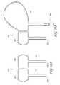
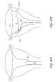
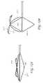
- FIGS. 1( a ) and 1 ( b )are top views, partly in section, of an embodiment of a device for distending a gynecological cavity, the device being constructed according to the teachings of the present invention and being shown in a compressed state and in an expanded state, respectively;
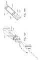
- FIGS. 2( a ) and 2 ( b )are fragmentary, schematic top views, partly in section, showing one way in which the device of FIGS. 1( a ) and 1 ( b ) may be used to distend a gynecological cavity, such as a uterine cavity;
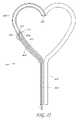
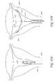
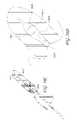
- FIGS. 3( a ) and 3 ( b )are top views, partly in section, of another embodiment of a device for distending a gynecological cavity, the device being constructed according to the teachings of the present invention and being shown in a compressed state and in an expanded state, respectively;
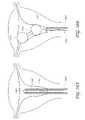
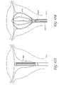
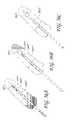
- FIG. 4is a fragmentary top view, partly in section, of still another embodiment of a device for distending a gynecological cavity, the device being constructed according to the teachings of the present invention and being shown in an expanded state;
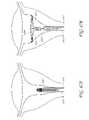
- FIGS. 5( a ) and 5 ( b )are top views, partly in section, of still yet another embodiment of a device for distending a gynecological cavity, the device being constructed according to the teachings of the present invention and being shown in a compressed state and in an expanded state, respectively;
- FIGS. 6( a ) through 6 ( h )are top views of a number of alternate embodiments to the device shown in FIGS. 5( a ) and 5 ( b ), the alternate embodiments being constructed according to the teachings of the present invention and being shown in their respective expanded states;
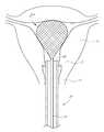
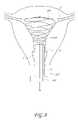
- FIG. 7is a top view, partly in section, of still yet another device for distending a gynecological cavity, the device being constructed according to the teachings of the present invention and being shown in an expanded state within a uterus;
- FIG. 8is a top view, partly in section, of still yet another device for distending a gynecological cavity, the device being constructed according to the teachings of the present invention and being shown in an expanded state within a uterus;
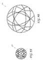
- FIGS. 9( a ) and 9 ( b )are top views of still yet another device for distending a gynecological cavity, the device being constructed according to the teachings of the present invention and being shown in a compressed state and in an expanded state, respectively;
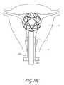
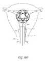
- FIGS. 10( a ) through 10 ( e )are schematic top views, partly in section, showing one way in which the device of FIGS. 9( a ) and 9 ( b ) may be used to distend a gynecological cavity, such as a uterine cavity;
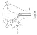
- FIGS. 11( a ) and 11 ( b )are top views, partly in section, of still yet another embodiment of a device for distending a gynecological cavity, the device being constructed according to the teachings of the present invention and being shown within a uterus in a compressed state and in an expanded state, respectively;
- FIGS. 12( a ) and 12 ( b )are top views, partly in section, of still yet another embodiment of a device for distending a gynecological cavity, the device being constructed according to the teachings of the present invention and being shown in a non-expanded state and in an expanded state, respectively;
- FIGS. 13( a ) and 13 ( b )are top views, partly in section, of still yet another embodiment of a device for distending a gynecological cavity, the device being constructed according to the teachings of the present invention and being shown in a non-expanded state and in an expanded state, respectively;
- FIG. 14is a top view of still yet another embodiment of a device for distending a gynecological cavity, the device being constructed according to the teachings of the present invention and being shown in an expanded state;
- FIGS. 15( a ) through 15 ( e )are schematic top views, partly in section, showing one way in which the device of FIG. 14 may be used to distend a gynecological cavity, such as a uterine cavity;
- FIGS. 16( a ) and 16 ( b )are fragmentary top and rear views, respectively, of an alternate embodiment to the device shown in FIG. 14 , the alternate embodiment being constructed according to the teachings of the present invention and being shown in its expanded state;
- FIGS. 17( a ) through 17 ( c )are perspective views of additional alternate embodiments to the device shown in FIG. 14 , the alternate embodiments being constructed according to the teachings of the present invention and being shown in their respective expanded states;
- FIGS. 18( a ) and 18 ( b )are section views of still yet another embodiment of a device for distending a gynecological cavity, the device being constructed according to the teachings of the present invention and being shown in a non-expanded state and in a partially-expanded state, respectively;
- FIG. 19is a section view of still yet another embodiment of a device for distending a gynecological cavity, the device being constructed according to the teachings of the present invention and being shown in a non-expanded state;
- FIGS. 20 ( a ) and 20 ( b )are top views, partly in section, of still yet another embodiment of a device for distending a gynecological cavity, the device being constructed according to the teachings of the present invention and being shown in a non-expanded state and in a partially expanded state, respectively;
- FIG. 21is a top view, partly in section, of still yet another embodiment of a device for distending a gynecological cavity, the device being constructed according to the teachings of the present invention and being shown in an expanded state with visualization means associated therewith;
- FIG. 22is a top view, partly in section, of still yet another embodiment of a device for distending a gynecological cavity, the device being constructed according to the teachings of the present invention and being shown in an expanded state with visualization means associated therewith;
- FIG. 23is a top view, broken away in part, of still yet another embodiment of a device for distending a gynecological cavity, the device being constructed according to the teachings of the present invention and being shown in an expanded state;
- FIG. 24is a top view, partly in section, of still yet another embodiment of a device for distending a gynecological cavity, the device being constructed according to the teachings of the present invention and being shown in an expanded state;
- FIG. 25is a top view, partly in section, of still yet another embodiment of a device for distending a gynecological cavity, the device being constructed according to the teachings of the present invention and being shown in an expanded state with a syringe attached thereto;
- FIG. 26is a top view, partly in section, of still yet another embodiment of a device for distending a gynecological cavity, the device being constructed according to the teachings of the present invention and being shown in an expanded state;
- FIG. 27is a top view, partly in section, of still yet another embodiment of a device for distending a gynecological cavity, the device being constructed according to the teachings of the present invention and being shown in an expanded state;
- FIG. 28is a top view, partly in section, of still yet another embodiment of a device for distending a gynecological cavity, the device being constructed according to the teachings of the present invention and being shown in an expanded state;
- FIGS. 29( a ) and 29 ( b )are top views, partly in section, illustrating a two-part method for distending a gynecological cavity in accordance with the teachings of the present invention
- FIG. 30is a top view of an alternate device for use in practicing the two-part distension method illustrated in FIGS. 29( a ) and 29 ( b );
- FIGS. 31( a ) and 31 ( b )are top views, partly in section, showing one way in which the device of FIG. 30 may be used to practice the two-part method of FIGS. 29( a ) and 29 ( b ); and
- FIGS. 32( a ) and 32 ( b )are top views, partly in section, showing an alternate device being used to practice the two-part method of FIGS. 29( a ) and 29 ( b ).
- FIGS. 33( a ) and 33 ( b )are top views, partly in section, illustrating an alternate embodiment for distending a gynecological cavity using an inflatable or bladder cage.
- FIGS. 34( a ) and 34 ( b )are top views, partly in section, illustrating an alternate embodiment for distending a gynecological cavity using a restricted balloon.
- FIGS. 35( a ) and 35 ( b )are top views, partly in section, illustrating an alternate embodiment for distending a gynecological cavity using a film air bladder having a pre-shaped structure.
- FIGS. 36( a ) and 36 ( b )are top views, partly in section, illustrating an alternate embodiment for distending a gynecological cavity using a spring mesh.
- FIGS. 37( a ) and 37 ( b )are top views, partly in section, illustrating an alternate embodiment for distending a gynecological cavity using an expandable foam pill.
- FIG. 38is a top view, partly in section, illustrating an alternate embodiment for distending a gynecological cavity using magnet blocks.
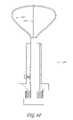
- FIG. 39is top view, partly in section, illustrating an alternate embodiment for distending a gynecological cavity using external and/or internal magnets.
- FIGS. 40( a ) and 40 ( b )are top views, partly in section, illustrating an alternate embodiment for distending a gynecological cavity using an extendible piston.
- FIGS. 41( a ) and 41 ( b )are top views, partly in section, illustrating an alternate embodiment for distending a gynecological cavity using a device with expandable arms.
- FIGS. 42( a ) and 42 ( b )are top views, partly in section, illustrating an alternate embodiment for distending a gynecological cavity using expandable hinged bars.
- FIGS. 43( a ) and 43 ( b )are top views, partly in section, illustrating an alternate embodiment for distending a gynecological cavity using an expandable clip.
- FIGS. 44( a ) and 44 ( b )are top views, partly in section, illustrating an alternate embodiment for distending a gynecological cavity using expandable wires, and in certain embodiments the wires are formed into a wisp or cage configuration.
- FIGS. 45( a ) and 45 ( b )are top views, partly in section, illustrating an alternate embodiment for distending a gynecological cavity using expandable bands.
- FIGS. 46( a ) and 46 ( b )are top views, partly in section, illustrating an alternate embodiment for distending a gynecological cavity using expandable bands having a central drive shaft.
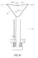
- FIGS. 47( a ) and 47 ( b )are top views, partly in section, illustrating an alternate embodiment for distending a gynecological cavity using expandable arms.
- FIGS. 48( a ) and 48 ( b )are top views, partly in section, illustrating an alternate embodiment for distending a gynecological cavity using a helical deformable anchor.
- FIGS. 49( a ) and 49 ( b )are top views, partly in section, illustrating an alternate embodiment for distending a gynecological cavity using expandable arms having an over center linkage.
- FIGS. 50( a ), 50 ( b ), and 50 ( c )are top views, partly in section, illustrating an alternate embodiment for distending a gynecological cavity using an expandable T-bar.
- FIGS. 51( a ) and 51 ( b )are top views, partly in section, illustrating an alternate embodiment for distending a gynecological cavity using a spine linkage.
- FIGS. 52( a ) and 52 ( b )are top views, partly in section, illustrating an alternate embodiment for distending a gynecological cavity using linked bars having springs and an actuation rod.
- FIGS. 53( a ) and 53 ( b )are top views, partly in section, illustrating an alternate embodiment for distending a gynecological cavity using nitinol wire having pivots.
- FIGS. 54( a ), 54 ( b ), 54 ( c ), and 54 ( d )are top views, partly in section, illustrating an alternate embodiment for distending a gynecological cavity using a bellows device.
- FIGS. 55( a ), 55 ( b ), 55 ( c ), 55 ( d ), and 55 ( e )are top views, partly in section, illustrating an alternate embodiment for distending a gynecological cavity using an umbrella device.
- FIGS. 56( a ), 56 ( b ), and 56 ( c )are top views, partly in section, illustrating an alternate embodiment for distending a gynecological cavity using an inflatable balloon.
- FIGS. 1( a ) and 1 ( b )there are shown top views, partly in section, of an embodiment of a device for distending a gynecological cavity, the device being constructed according to the teachings of the present invention and being represented generally by reference numeral 11 . Additional features, methods and systems relating to the present invention are disclosed in U.S. patent application Ser. No. 11/923,357 filed Oct. 24, 2007, entitled Mechanical Distension Systems for Performing a Medical Procedure in a Remote Space, the disclosure of which is hereby incorporated in its entirety herein by reference.
- Basket 21may be a resiliently-biased foldable weave of filaments 22 made of Nitinol (nickel-titanium alloy) shape-memory alloy, spring steel or a similar shape-memory material. Basket 21 may be constructed so that, when fully expanded within a uterus, it distends the uterus or a portion of the uterus to a desired extent. If desired, basket 21 may be constructed so that its expanded shape mimics the shape of the uterus.
- basket 21is constructed to distend the uterus to an extent equivalent to that which would be attained using the above-described conventional fluid distension technique at a pressure of at least 40 mm Hg but not greater than 100 mm Hg, often within the range of from about 60 mm Hg and about 80 mm Hg and preferably at a pressure of approximately 70 mm Hg for a typical patient.
- basket 21may be constructed to provide a uniform radial force in all directions or may be constructed to provide different radial forces in different directions, such as along the coronal and sagittal planes.
- the woven filaments 22 making up basket 21may be sized and spaced (e.g., diameter, length, width) to effectively cover a small portion of the contacted surface area, thereby leaving large “windows” between adjacent filaments 22 through which diagnostic and/or therapeutic procedures may be performed; alternatively, filaments 22 may be sized and spaced to cover a large portion of the contacted surface area, with comparatively smaller “windows.” It should be noted that, by appropriately sizing and positioning such “windows” over a target tissue, basket 21 may cause a target tissue to avulse through a window and into the interior of basket 21 , where it may then be treated.
- Device 11may additionally comprise an elongated shaft 31 , shaft 31 having a proximal end 33 and a distal end 35 .
- Distal end 35 of shaft 31may be coupled to basket 21 so that placement of basket 21 may be effected by moving shaft 31 .
- Shaft 31may be a solid member or may be a tubular structure.
- Device 11may further comprise an outer sheath 41 .
- Sheath 41which may be a unitary, tubular member, has a proximal end 47 and a distal end 49 .
- Distal end 49is adapted to be inserted into the uterus transcervically, with proximal end 47 preferably remaining external to the patient.
- the outer diameter of sheath 41(or at least that portion of sheath 41 inserted into the patient) is preferably less than about 5.5 mm.
- sheath 41may be bendable along its length.
- Shaft 31may be slidably disposed within sheath 41 , with proximal end 33 of shaft 31 preferably extending proximally relative to proximal end 47 of sheath 41 to facilitate access thereto by medical personnel.
- proximal end 33 of shaft 31may be coupled to a handle, pull-wires, or comparable structure that extends proximally relative to the proximal end 47 of sheath 41 or that is otherwise easily accessible to medical personnel.
- basket 21may be positioned within sheath 41 , where it is maintained in a compressed state by sheath 41 , or may be positioned distally relative to sheath 41 , where it is free to expand to its expanded state.
- FIGS. 2( a ) and 2 ( b )there is shown one way in which device 11 may be used to distend a gynecological cavity, in particular, a uterine cavity.
- a gynecological cavityin particular, a uterine cavity.
- such instrumentsmay be inserted transcervically into uterus U by being inserted alongside of, but not through, sheath 41 .
- shaft 31is pulled proximally relative to sheath 41 until basket 21 is retracted into sheath 41 , where it is compressed by sheath 41 .
- Device 11may then be withdrawn from the patient.
- a separate introducer devicemay first be inserted transcervically into the patient, with device 11 thereafter inserted into the patient through a lumen in the introducer device. It should further be noted that, where such a separate introducer device is first inserted into the patient, sheath 41 may be omitted from device 11 , with the lumen of the introducer device serving the same purpose as sheath 41 of maintaining the expandable means in a compressed state during delivery to the uterus and withdrawal from the uterus.
- basket 21may or may not be resiliently biased and its expansion may be caused or assisted by other mechanical means, such as by an inflatable balloon, advanceable push rods which exert radial forces upon different portions of basket 21 and/or other mechanical means.
- FIGS. 3( a ) and 3 ( b )there are shown top views, partly in section, of another embodiment of a device for distending a gynecological cavity, the device being constructed according to the teachings of the present invention and being represented generally by reference numeral 51 .
- Device 51is similar in certain respects to device 11 , the principal difference between the two devices being that, whereas device 11 includes expandable means in the form of basket 21 , device 51 includes expandable means in the form of a self-expanding loop 53 .
- Loop 53is joined at its proximal end to shaft 31 and may be made from Nitinol (nickel-titanium alloy) shape-memory alloy, spring steel or a similar shape memory material. Loop 53 is appropriately constructed so that, when positioned within sheath 41 , it is maintained in a radially compressed state ( FIG. 3( a )) and so that, when positioned distally beyond sheath 41 , it self-expands ( FIG.
- loop 53is constructed to distend a uterus to an extent equivalent to that which would be attained using the above-described conventional fluid distension technique at a pressure of at least 40 mm Hg but not greater than 100 mm Hg and preferably at a pressure of approximately 70 mm Hg.
- Device 51may be used in a fashion similar to that described above in connection with device 11 .
- FIG. 4there is shown a top view, partly in section, of still another embodiment of a device for distending a gynecological cavity, the device being constructed according to the teachings of the present invention and being represented generally by reference numeral 71 .
- Device 71is similar in most respects to device 51 , the principal difference between the two devices being that, whereas device 51 includes expandable means in the form of loop 53 , device 71 includes expandable means in the form of a self-expanding structure 73 .
- Structure 73includes a resilient loop 74 , which is similar to loop 53 , and further includes a resilient arm 75 , which is fixed at its proximal end 76 to the proximal end of loop 74 and is fixed at its distal end 77 to the distal end of loop 74 .
- arm 75serves to distend the gynecological cavity in a direction substantially perpendicular to that of loop 74 .
- Structure 73is joined at its proximal end to shaft 31 and may be made from Nitinol (nickel-titanium alloy) shape-memory alloy, spring steel or a similar shape memory material.
- Structure 73is appropriately dimensioned so that, when positioned within sheath 41 , it is maintained in a radially compressed state and so that, when positioned distally beyond sheath 41 , it self-expands to distend a gynecological cavity, such as a uterine cavity, or a portion thereof.
- structure 73is constructed to distend the uterus to an extent equivalent to that which would be attained using the above-described conventional fluid distension technique at a pressure of at least 40 mm Hg but not greater than 100 mm Hg and preferably at a pressure of approximately 70 mm Hg.
- Device 71may be used in a fashion similar to that described above in connection with device 11 .
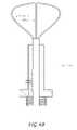
- FIGS. 5( a ) and 5 ( b )there are shown top views, partly in section, of still yet another embodiment of a device for distending a gynecological cavity, the device being constructed according to the teachings of the present invention and being represented generally by reference numeral 101 .
- Device 101which is particularly well-suited for distending the uterus of a patient, may comprise an outer sheath 103 .
- Sheath 103which may be a unitary, tubular member, may be shaped to include a longitudinal lumen 106 , a proximal end 107 and a distal end 109 .
- Proximal end 107which may remain external to the patient, may be shaped to include an outwardly-extending radial flange 108 .
- Flange 108may be appropriately dimensioned to accommodate, on its distal surface 110 , two fingers of an operator, each finger on an opposite side of lumen 106 .
- Distal end 109may be adapted to be inserted into the uterus transcervically.
- the outer diameter of that portion of sheath 103 inserted into the patientis preferably less than about 5.5 mm.
- Device 101also may comprise an elongated shaft 111 , shaft 111 having a proximal end 113 and a distal end 115 .
- Proximal end 113may be shaped to include an outwardly-extending radial flange 117 , flange 117 being appropriately dimensioned to prevent its insertion into lumen 106 of sheath 103 .
- Substantially the remainder of shaft 111may be slidable within lumen 106 of sheath 103 .
- Device 101additionally may comprise expandable means.
- said expandable meansmay comprise a plurality of elongated prongs 121 .
- Each prong 121may have a proximal end 123 and a distal end 125 , each proximal end 123 being fixed to distal end 115 of shaft 111 , each distal end 125 being free.
- Prongs 121may be equally spaced apart around the perimeter of distal end 115 of shaft 111 and may be constructed to be outwardly-biased relative to the longitudinal axis of shaft 111 .
- Prongs 121may be made of Nitinol (nickel-titanium alloy) shape-memory alloy, spring steel, a shape-memory polymer, or a similar shape-memory material. As can be seen, by appropriately positioning distal end 115 of shaft 111 relative to distal end 107 of sheath 103 , prongs 121 may be positioned within sheath 103 , where they are maintained in a compressed state by sheath 103 , or may be positioned distally relative to sheath 103 , where they are free to assume their expanded configuration.
- Nitinolnickel-titanium alloy
- Prongs 121may be configured so that, when unrestrained by sheath 103 , they distend the uterus or a portion of the uterus to a desired extent. Preferably, prongs 121 distend the uterus to an extent equivalent to that which would be attained using the above-described conventional fluid distension technique at a pressure of at least 40 mm Hg but not greater than 100 mm Hg and preferably at a pressure of approximately 70 mm Hg.
- prongs 121may be constructed from a resectable material so that an obstructing prong (e.g., a prong positioned over a target, such as a fibroid) may be removed, for example, by a morcellating device.
- an obstructing pronge.g., a prong positioned over a target, such as a fibroid
- Device 101further may comprise means for biasing shaft 111 proximally relative to sheath 103 .
- said biasing meansmay comprise a coil spring 131 .
- Coil spring 131may be inserted coaxially over shaft 111 , with the proximal end 133 of spring 131 engaging proximal end 113 of shaft 111 and with the distal end 135 of spring 131 engaging proximal end 105 of sheath 103 .
- Spring 131serves to bias shaft 111 proximally relative to sheath 103 and, therefore, biases prongs 121 towards their non-expanded configuration.
- Device 101further may comprise disengageable means for permitting movement of shaft 111 distally, but not proximally, relative to sheath 103 .
- said meansmay comprise a ratchet 141 , a pawl 143 and a spring 145 .
- Ratchet 141may be integrally formed along a portion of the length of shaft 111 .
- Pawl 143may be partially inserted through a transverse opening 144 in sheath 103 .
- Spring 145may be inserted coaxially over a portion of pawl 143 to bias pawl 143 towards engagement with ratchet 141 .
- Pawl 143may be shaped to include a handle 147 .
- Handle 147may be used to pull pawl 143 away from ratchet 141 when one wishes to disengage pawl 143 from ratchet 141 .
- a gynecological cavitysuch as a uterine cavity
- shaft 111may then move shaft 111 distally relative to sheath 103 until prongs 121 emerge fully from distal end 107 of sheath 103 , whereby prongs 121 assume their expanded configuration (as in FIG. 5( b )).
- Such movement of shaft 111 relative to sheath 103may be accomplished by operating device 101 like a syringe, with the forefinger and the middle finger of one hand spaced apart against distal surface 110 of flange 108 and with the thumb of the same hand positioned against the proximal surface of proximal end 113 of shaft 111 .
- spring 131becomes compressed; however, engagement of pawl 143 with ratchet 141 prevents spring 131 from returning to its decompressed state.
- prongs 121With prongs 121 in their expanded configuration, the walls of the uterus are distended, and one may perform one or more desired diagnostic and/or therapeutic procedures within the uterus. Such procedures may be performed by inserting one or more instruments coaxially through sheath 103 alongside of shaft 111 or, if shaft 111 is tubular, by inserting such one or more instruments coaxially through shaft 111 (and, thereafter, between adjacent prongs 121 ). Alternatively, such instruments may be inserted transcervically into uterus U by being inserted alongside of, but not through, sheath 103 . When distension of the uterus is no longer desired, pawl 143 is pulled away from engagement with ratchet 141 .
- coil 131 and/or the combination of ratchet 141 , pawl 143 , and spring 145could be omitted from device 101 , in which case the operator would manually maintain the relative axial positions of shaft 111 and sheath 103 .
- a separate introducer devicemay first be inserted transcervically into the patient, with device 101 thereafter inserted into the patient through a lumen of the introducer device.
- sheath 103(as well as coil 131 , ratchet 141 , pawl 143 and spring 145 ) may be omitted from device 101 , with the lumen of the introducer device serving the same purpose as sheath 103 of maintaining the expandable means in a compressed state during delivery to the uterus and withdrawal from the uterus.
- FIGS. 6( a ) through 6 ( h )there are shown top views, partly in section, of a number of alternate embodiments to device 101 , said alternate embodiments differing from device 101 only in the construction of their respective self-expanding, expandable means. More specifically, in FIG. 6( a ), there is shown a device 151 , device 151 comprising expandable means in the form of a self-expanding loop 153 . Loop 153 may have a quasi-triangular shape as shown to correspond generally to the shape of a uterus. In FIG.
- a device 161comprising expandable means in the form of a pair of self-expanding loops 163 - 1 and 163 - 2 arranged in a whisk-like configuration, with the distal end of loop 163 - 2 being positioned just inside the distal end of loop 163 - 1 and with loop 163 - 2 being oriented generally perpendicularly to the plane of loop 163 - 1 .
- loop 163 - 2is positioned just inside the distal end of loop 163 - 1
- device 161may be modified so that loops 163 - 1 and 163 - 2 are of equal size and/or have a common distal end.
- the radial forces applied by loops 163 - 1 and 163 - 2may be substantially equal; alternatively, the radial forces applied by loops 163 - 1 and 163 - 2 may differ, for example, to apply different forces in the coronal and sagittal planes.
- a device 181there is shown a device 181 , device 181 comprising expandable means in the form of a self-expanding cage-like structure 183 , structure 183 comprising a plurality of rod-like members 185 - 1 through 185 - 4 pivotally joined end-to-end at joints 187 - 1 , 187 - 2 and 187 - 3 , respectively.
- Structure 183may have a heart-like shape as shown to correspond generally to the shape of a uterus.
- FIG. 6( d )there is shown a device 191 , device 191 comprising expandable means in the form of a pair of self-expanding, cage-like structures 193 and 195 .
- Structure 195has a distal end positioned just inside the distal end of structure 193 , with structure 195 being oriented generally perpendicularly to the plane of structure 193 .
- the radial forces applied by cage-like structures 193 and 195may be substantially equal or may differ, for example, to apply different forces in the coronal and sagittal planes.
- FIG. 6( e )there is shown a device 197 , device 197 comprising expandable means in the form of an asymmetric, self-expanding loop 199 .
- Loop 199may be useful in situations in which it is advantageous to distend only a portion of the uterus in order to create ample space to observe and/or to treat the non-distended portion.
- device 201comprising expandable means similar to the expandable means of device 161 , except that device 201 comprises a symmetric loop 203 and an asymmetric loop 205 arranged in a whisk-like configuration, with the distal end of loop 205 being positioned just inside the distal end of loop 203 and with loop 205 being oriented generally perpendicularly to the plane of loop 203 but positioned only to one side of the plane of loop 203 .
- device 201may be useful in situations in which it is advantageous to distend only a portion of the uterus.
- a device 211device 211 comprising expandable means in the form of an asymmetric, self-expanding, jointed structure 213 .
- device 211may be useful in situations in which it is advantageous to distend only a portion of the uterus.
- FIG. 6( h )there is shown a device 221 , device 221 comprising expandable means in the form of a pair of cage-like structures 223 and 225 .
- Device 221is similar to device 191 , the principal difference between the two devices being that cage-like structure 225 is asymmetric and is positioned only to one side of structure 223 .
- device 221may be useful in situations in which it is advantageous to distend only a portion of the uterus.
- FIG. 7there is shown a fragmentary top view, partly in section, of still yet another embodiment of a device for distending a gynecological cavity, the device being constructed according to the teachings of the present invention and being represented generally by reference numeral 231 .
- Device 231which is shown in an expanded state within a uterus, is similar in many respects to device 11 , the principal difference between the two devices being that, whereas device 11 comprises expandable means in the form of self-expanding basket 21 , device 231 comprises expandable means that includes a self-expanding whisk 233 that is partially or completely covered on its inside or outside surface by a cover 235 .
- whisk 233is constructed to distend the uterus to an extent equivalent to that which would be attained using the above-described conventional fluid distension technique at a pressure of at least 40 mm Hg but not greater than 100 mm Hg and preferably at a pressure of approximately 70 mm Hg.
- Cover 235may be made, for example, from a suitable fabric or polymer. In the present embodiment, cover 235 only partially covers whisk 233 , with the uncovered portion of whisk 233 forming a window 237 .
- the covered portions of whisk 233may be used to keep the non-targeted portions of the gynecological cavity from entering into the interior space of whisk 233 whereas window 237 may be used to provide access to a target tissue through the interior space of whisk 233 or may be used to avulse a target tissue into the interior space of whisk 233 .
- whisk 233may be deployed within a gynecological cavity and then oriented, for example, by rotating shaft 31 (preferably partially compressing whisk 233 before rotating shaft 31 ), so that window 237 is aligned with a target mass, such as a fibroid.
- the radial pressure exerted by whisk 233 on the tissue surrounding the target massmay cause the target mass to avulse through the window 237 and into the interior space of whisk 233 , where it may then be treated.
- whisk 233 and/or cover 235may be coated, impregnated or otherwise include one or more drugs, such as clotting agents and anesthetics.
- the drugmay be “released” by a clinician on demand, such as by an integral iontophoretic delivery element (e.g., integral to whisk 233 ), or by applying a force to an integral pressure-activated drug depot (e.g., integral to whisk 233 ), and cover 235 may be used to administer such drugs to tissue by contact with the tissue.
- whisk 233 and/or cover 235may be coated or treated with one or more compounds to change a property, such as echogenicity, lubricity and radiopacity.
- FIG. 8there is shown a top view of still yet another embodiment of a device for distending a gynecological cavity, the device being constructed according to the teachings of the present invention and being represented generally by reference numeral 241 .
- Device 241which is shown in an expanded state within a uterus, is similar in certain respects to device 11 .
- One difference between the two devicesis that, whereas device 11 comprises basket 21 and shaft 31 , device 241 instead comprises a self-expanding wire 243 .
- Wire 243is appropriately constructed so that, when pushed distally through sheath 41 or a similar introducer device, it adopts a spiral shape that may mimic the shape of the uterus or other gynecological cavity.
- wire 243is constructed to distend the uterus to an extent equivalent to that which would be attained using the above-described conventional fluid distension technique at a pressure of at least 40 mm Hg but not greater than 100 mm Hg and preferably at a pressure of approximately 70 mm Hg.
- a ball 245 or similar structuremay be provided on the distal end of wire 243 to prevent perforating tissue within the cavity.
- a Touhy Borst valve 247 or similar structuremay be positioned at the proximal end of sheath 41 to maintain wire 243 at a desired longitudinal position relative to sheath 41 .
- FIGS. 9( a ) and 9 ( b )there are shown top views of still yet another embodiment of a device for distending a gynecological cavity, the device being constructed according to the teachings of the present invention and being represented generally by reference numeral 251 .
- Device 251which is shown in a compressed state in FIG. 9( a ) and in an expanded state in FIG. 9( b ), is a self-expanding structure in the form of a Hoberman sphere (icosidodecahedron). Device 251 is appropriately dimensioned so that, in a compressed state, it may be passed through the vagina and the cervix of a patient and, in its expanded state, it may distend the uterus of a patient to a desired extent.
- Hoberman sphereicosidodecahedron
- device 251is constructed to distend the uterus to an extent equivalent to that which would be attained using the above-described conventional fluid distension technique at a pressure of at least 40 mm Hg but not greater than 100 mm Hg and preferably at a pressure of approximately 70 mm Hg.
- FIGS. 10( a ) through 10 ( e )there is shown a series of top views, illustrating one way in which device 251 may be used to distend a gynecological cavity, in particular, a uterine cavity.
- device 251is loaded into a lumen 253 of a sheath 255 or other suitable gynecological introducer device, lumen 253 being appropriately dimensioned to maintain device 251 in a compressed state.
- FIG. 10( a )the lumen 253 of a sheath 255 or other suitable gynecological introducer device, lumen 253 being appropriately dimensioned to maintain device 251 in a compressed state.
- sheath 255may be re-introduced into the patient through the vagina and the cervix, and a snare 260 may be distally inserted through lumen 253 to grab device 251 .
- snare 260 and device 251are then withdrawn proximally through lumen 253 , device 251 being compressed by lumen 253 .
- device 251could be modified to include a tie-line or the like having a first end secured to device 251 and a second end remaining external to the patient. In this manner, instead of using a snare to pull device 251 through lumen 253 , one could simply pull proximally on tie-line to pull device 251 through lumen 253 .
- FIGS. 11( a ) and 11 ( b )there are shown top views, partly in section, of still yet another embodiment of a device for distending a gynecological cavity, the device being constructed according to the teachings of the present invention and being represented generally by reference numeral 271 .
- Device 271is similar in many respects to device 11 .
- One difference between the two devicesis that, whereas device 11 includes a basket 21 fixed to distal end 33 of shaft 31 , device 271 instead includes a self-expanding basket 273 , a tie-line 275 having a proximal end 276 preferably extending proximally from sheath 41 and a distal end fixed to basket 273 , and an ejector rod 277 slidably and removably mounted within sheath 41 for ejecting basket 273 distally from sheath 41 .
- basket 273may be loaded into sheath 41 or a similar introducer device, with proximal end 276 of line 275 preferably extending proximally from sheath 41 .
- the distal end of the thus-loaded sheathmay then be inserted through the vagina V and the cervix C of a patient.
- Ejector rod 277may then be inserted distally into sheath 41 until basket 273 is ejected from sheath 41 into the uterus U of the patient, at which time basket 273 self-expands to distend the uterus.
- proximal end 276 of line 275is held in place while ejector rod is inserted into sheath 41 to ensure that end 276 remains external to sheath 41 .
- ejector rod 277may then be removed proximally from sheath 41 .
- device 271may be modified to replace basket 273 with other self-expanding structures that may be compressed and withdrawn from a gynecological cavity by being pulled into sheath 41 or a similar introducer device.
- FIGS. 12( a ) and 12 ( b )An example of such a device is shown in FIGS. 12( a ) and 12 ( b ) and is represented generally by reference numeral 301 .
- Device 301is similar in many respects to device 151 , the principal difference between the two devices being that, whereas device 151 includes a self-expanding loop 153 , device 301 includes (i) a mechanically-expandable loop 303 and (ii) a tensioning wire 305 .
- Tensioning wire 305is fixed at one end to the distal end 307 of loop 303 .
- the opposite end of tensioning wire 305is passed through a lumen (not shown) in shaft 111 and terminates proximally beyond proximal end 113 of shaft 111 .
- Device 301may be used in a fashion similar to that for device 151 , the only difference being that, after loop 303 has been inserted into the uterus or other gynecological cavity, loop 303 must be actively expanded by pulling proximally on tensioning wire 305 .
- device 301may include a hook or similar structure around which the proximal end of tensioning wire 305 may be wrapped or otherwise fixed in order to maintain a constant amount of tension on wire 305 .
- loop 303distends the uterus to an extent equivalent to that which would be attained using the above-described conventional fluid distension technique at a pressure of at least 40 mm Hg but not greater than 100 mm Hg and preferably at a pressure of approximately 70 mm Hg.
- tensioning wire 305may be moved distally to its original position, thereby restoring loop 303 to its non-expanded state.
- device 301One notable attribute of device 301 is that the distending pressure exerted by device 301 may be varied by varying the amount of tension applied to tensioning wire 305 .
- FIGS. 13( a ) and 13 ( b )Another example of a device having expandable means that are not self-expanding is shown in FIGS. 13( a ) and 13 ( b ) and is represented generally by reference numeral 351 .
- Device 351is similar in many respects to device 181 , the principal difference between the two devices being that, whereas device 181 includes self-expanding cage 183 , device 351 includes (i) a mechanically-expandable cage 353 and (ii) a tensioning wire 355 .
- Tensioning wire 355is fixed at one end to the distal end 357 of cage 353 .
- the opposite end of tensioning wire 355is passed through a lumen (not shown) in shaft 111 and terminates proximally beyond proximal end 113 of shaft 111 .
- Device 351may be used in a fashion similar to that for device 181 , the only difference being that, after cage 353 has been inserted into the uterus or other gynecological cavity, cage 353 must be actively expanded by pulling proximally on tensioning wire 355 .
- device 351may include a hook or similar structure around which the proximal end of tensioning wire 355 may be wrapped or otherwise fixed in order to maintain a constant amount of tension on wire 355 .
- cage 353distends the uterus to an extent equivalent to that which would be attained using the above-described conventional fluid distension technique at a pressure of at least 40 mm Hg but not greater than 100 mm Hg and preferably at a pressure of approximately 70 mm Hg.
- tensioning wire 355may be moved distally to its original position, thereby restoring cage 353 to its non-expanded state.
- device 351may be used to exert a variable distending pressure by varying the amount of tension applied to tensioning wire 355 .
- FIG. 14there is shown a top view of still yet another embodiment of a device for distending a gynecological cavity, the device being constructed according to the teachings of the present invention and being represented generally by reference numeral 371 .
- Device 371may comprise a proximal inflation line 373 and a distal balloon portion 375 , line 373 and balloon portion 375 being in fluid communication with one another.
- An inflation valve 377may be disposed at the proximal end of inflation line 373 .
- balloon portion 375has an asymmetric- or lobed-shape to distend approximately one-half of a uterus or similar gynecological cavity. In this manner, balloon portion 375 may occupy a portion of a uterus while the remaining, unoccupied portion may be left accessible for observation, diagnosis and/or treatment. Balloon portion 375 may be either compliant or non-compliant.
- FIGS. 15( a ) through 15 ( e )there is schematically shown one way in which device 371 may be used.
- the distal end of device 371may be inserted through the vagina V and the cervix C of the patient through a sheath 379 or similar introducer device.
- device 371may be moved distally relative to sheath 379 so that balloon portion 375 may be positioned within the uterus U.
- FIG. 15( a ) through 15 ( e )there is schematically shown one way in which device 371 may be used.
- the distal end of device 371may be inserted through the vagina V and the cervix C of the patient through a sheath 379 or similar introducer device.
- device 371may be moved distally relative to sheath 379 so that balloon portion 375 may be positioned within the uterus U.
- fluidmay be dispensed from syringe 380 through line 373 and into balloon portion 375 , thereby causing balloon portion 375 to become inflated and the uterus U to become distended.
- the fluid dispensed from syringe 380may be, for example, a gas, such as carbon dioxide, or a liquid, such as a saline solution.
- syringe 380may be removed from device 371 .
- FIG. 15( e )when distension of the uterus U is no longer desired, syringe 380 may be reattached to device 371 and balloon portion 375 deflated. Device 371 may then be withdrawn from the patient.
- FIGS. 16( a ) and 16 ( b )there are shown fragmentary top and rear views, respectively, of an alternate balloon portion to the balloon portion 375 of device 371 , the alternate balloon portion being represented by reference numeral 401 .
- balloon portion 401has an I-shape and, therefore, may be well-suited for contacting opposing walls of a uterus or similar gynecological cavity in such a way as to keep the cavity distended.
- Each of balloon portions 421 , 441 and 461may be dimensioned to contact opposing walls of a uterus or other gynecological cavity in such a way as to keep the cavity distended.
- Further alternate balloon portionsmay include, for example, annular, annular oval, rectangular, and T-shaped balloon portions.
- FIGS. 18( a ) and 18 ( b )there are shown section views of still yet another embodiment of a device for distending a gynecological cavity, the device being constructed according to the teachings of the present invention and being represented generally by reference numeral 481 .
- Device 481is similar in certain respects to device 371 , the principal difference between the two devices being that, whereas device 371 includes a single balloon portion 373 , device 481 instead includes two balloon portions 483 and 485 .
- Balloon portion 483is fluidly connected to an inflation line 487
- balloon portion 485is fluidly connected to an inflation line 489 .
- Inflation valves 491 and 493are positioned at the proximal ends of inflation lines 487 and 489 , respectively.
- balloon portions 483 and 485are independently-operable, one may inflate one without inflating the other.
- a desirable attribute of device 481is that, with a single insertion of device 481 into a patient, one may inflate only one of balloon portions 483 and 485 , for example, to create the space necessary to perform a procedure on one side of a gynecological cavity, and then inflate only the other one of balloon portions 483 and 485 , for example, to create the space necessary to perform a procedure on the opposite side of the cavity.
- FIG. 19there is shown a section view of still yet another embodiment of a device for distending a gynecological cavity, the device being constructed according to the teachings of the present invention and being represented generally by reference numeral 501 .
- Device 501is similar in certain respects to device 481 , the principal difference between the two devices being that, whereas device 481 includes two independently-operable balloon portions 483 and 485 , device 501 includes three independently-operable balloon portions 503 , 505 and 507 .
- Balloon portion 503is fluidly connected to an inflation line 511
- balloon portion 505is fluidly connected to an inflation line 513
- balloon portion 507is fluidly connected to an inflation line 515 .
- Inflation valves 517 , 519 and 521are positioned at the proximal ends of inflation lines 511 , 513 and 515 , respectively.
- FIGS. 20( a ) and 20 ( b )there are shown top views, partly in section, of still yet another embodiment of a device for distending a gynecological cavity, the device being constructed according to the teachings of the present invention and being represented generally by reference numeral 551 .
- Device 551may include a scissor jack 553 .
- Scissor jack 553which may be conventional in configuration, is preferably dimensioned for use in a gynecological cavity, such as the uterus. Consequently, scissor jack 553 preferably has a maximum length, as measured from proximal end 555 to distal end 557 , of about 4-10 cm.
- scissor jack 553is preferably constructed so that, when expanded, jack 553 distends the uterus to an extent equivalent to that which would be attained using the above-described conventional fluid distension technique at a pressure of at least 40 mm Hg but not greater than 100 mm Hg and preferably at a pressure of approximately 70 mm Hg.
- Device 551may additionally include a jack crank 561 .
- Jack crank 561may have a hook 563 or similar structure at its distal end suitable for mating with a loop 565 at proximal end 555 of jack 553 .
- crank 561coupled to jack 553 , for example, by inserting hook 563 through loop 565 , one may rotate crank 561 about its longitudinal axis to cause jack 553 to expand laterally.
- Device 551may further include a delivery sheath 571 .
- Sheath 571which may be a unitary tubular member, may be shaped to include a proximal end (not shown), a distal end 573 , and a longitudinal lumen 575 .
- Lumen 575may be dimensioned to permit jack 553 to be passed therethrough, particularly with jack 553 is in its non-expanded state.
- Distal end 573may be adapted to be inserted into the uterus transcervically, with the proximal end of sheath 571 remaining external to the patient.
- the outer diameter of that portion of sheath 571 inserted into the patientis preferably less than about 5.5 mm.
- crank 561may be coupled to jack 553 , and jack 553 may then be inserted distally into lumen 575 of sheath 571 . Distal end 573 of sheath 571 may then be inserted through the vagina and the cervix of the patient. Next, jack 553 may be moved distally through distal end 573 of sheath 571 and into the uterus of the patient. Next, crank 561 may be rotated about its longitudinal axis, thereby causing jack 553 to expand laterally. Preferably, crank 561 is rotated until jack 553 engages opposing walls of the uterus and distends the uterus to a desired extent.
- crank 561may be decoupled from jack 553 and removed proximally from the patient.
- crank 561may be decoupled from jack 553 and removed proximally from the patient.
- onemay re-insert crank 561 through shaft 571 , re-attach crank 561 to jack 553 , and rotate crank 561 in the opposite direction to return jack 553 to its non-expanded state.
- jack 553 and crank 561may then be withdrawn proximally from the patient through sheath 571 .
- jack 553 and crank 561may be coupled together in the present embodiment by means of a hook and loop mechanism, jack 553 and crank 561 may be coupled together by other means, such as by magnets.
- the distension device of the present inventionmay be designed to perform one or more additional functions.
- An example of such a multi-purpose deviceis shown in FIG. 21 and is represented by reference numeral 601 .
- Device 601which may be used both to distend a gynecological cavity and to permit observation of the inside of the gynecological cavity, may include elongated, resilient members 603 and 605 .
- Members 603 and 605may be arranged relative to one another so that their respective proximal portions form a unified shaft 607 and so that their respective distal portions form expandable means.
- said expandable meanscomprises a self-expanding heart-shaped structure 609 .
- structure 609when structure 609 expands, structure 609 distends the uterus or other gynecological cavity to an extent equivalent to that which would be attained using the above-described conventional fluid distension technique at a pressure of at least 40 mm Hg but not greater than 100 mm Hg and preferably at a pressure of approximately 70 mm Hg.
- Member 603is a tubular structure having an open proximal end (not shown) and an open distal end 610 . In this manner, the distal end 612 of fiber optics 611 may be passed through member 603 and into the gynecological cavity to permit illumination and/or observation of the cavity.
- the distal end of device 601may be inserted into a gynecological cavity, such as a uterus, using an appropriately dimensioned introducer device.
- the proximal end of device 601preferably remains external to the patient.
- structure 609While positioned within the introducer device, structure 609 is compressed to a small profile. However, once structure 609 passes completely through the introducer device, structure 609 self-expands to its expanded state, where it distends the gynecological cavity.
- the distal end 612 of fiber optics 611may then be passed through member 603 and into the distended cavity.
- the proximal end of optics 611preferably remains external to the patient.
- fiber optics 611may be withdrawn proximally from member 603 .
- device 601may be removed from the patient by withdrawing structure 609 through the introducer device, the introducer device serving to compress structure 609 .
- device 601may be used to visualize the uterus from the vantage point of the uterine fundus, as opposed to the cervical-uterine junction, which would be the case if one merely inserted the fiber optics into the uterus through an introducer device.
- FIG. 22there is shown a top view, partly in section, of another embodiment of a multi-purpose device, the multi-purpose device being constructed according to the teachings of the present invention and being represented by reference numeral 651 .
- Device 651is similar in most respects to device 601 . However, one difference between the two devices is that device 651 may include an elongated, resilient member 653 , instead of elongated, resilient member 603 . Member 653 differs principally from member 603 in that member 653 may additionally include (i) an inwardly-facing, transverse opening 655 at an intermediate location within its distal portion and (ii) an integrally-formed, hinged deflector 657 for deflecting fiber optics 611 through opening 655 . As in the present embodiment, deflector 657 may be biased in the direction of opening 655 .
- device 651may additionally include a wire 659 fixed at its distal end 660 to deflector 657 so that, by pulling proximally on wire 659 , deflector 657 may be pivoted away from opening 655 .
- the proximal end of wire 659preferably remains external to the patient.
- a desirable attribute of device 651is that it may be used to observe the uterus from a plurality of alternate vantage points.
- FIG. 23there is shown a top view, broken away in part, of another embodiment of a multi-purpose device, the multi-purpose device being constructed according to the teachings of the present invention and being represented by reference numeral 701 .
- Device 701which may be used both to distend a gynecological cavity and to illuminate the inside of the gynecological cavity, may include an elongated member 702 shaped to include a proximal shaft portion 703 and distal expandable means.
- said distal expandable meansincludes a self-expanding loop 705 .
- loop 705distends the uterus or other gynecological cavity to an extent equivalent to that which would be attained using the above-described conventional fluid distension technique at a pressure of at least 40 mm Hg but not greater than 100 mm Hg and preferably at a pressure of approximately 70 mm Hg.
- member 702may be designed so that light inputted at its proximal end is both transmitted along its length and scattered through its side wall. This may be accomplished, for example, by incorporating particulate matter 706 , such as titanium dioxide particles, into a light-conductive material, such as silicone. The light-scattering particles may be located over only a portion of member 702 (for example, only within loop 705 ) or may be dispersed over the entirety of its length.
- a light source connector 707may be disposed at the proximal end 709 of member 702 to permit a light source (not shown) to be coupled to member 702 .
- the distal end of device 701may be inserted into a gynecological cavity, such as a uterus, using an appropriately dimensioned introducer device.
- the proximal end of device 701preferably remains external to the patient.
- loop 705While positioned within the introducer device, loop 705 is compressed to a small profile. However, once loop 705 passes completely through the introducer device, loop 705 self-expands to its expanded state, where it distends the gynecological cavity.
- a light sourcemay then be connected to connector 707 . The input of light into member 702 causes light to be scattered from member 702 , thereby illuminating the cavity.
- the light sourcemay be disconnected from connector 707 .
- device 701may be removed from the patient by withdrawing loop 705 through the introducer device, the introducer device serving to compress loop 705 .
- FIG. 24there is shown a top view, partly in section, of another embodiment of a multi-purpose device, the multi-purpose device being constructed according to the teachings of the present invention and being represented by reference numeral 751 .
- Device 751which may be used both to distend a gynecological cavity and to illuminate the inside of the gynecological cavity, may include an elongated member 752 shaped to include a proximal shaft portion 753 and distal expandable means.
- said distal expandable meansincludes a self-expanding loop 755 .
- loop 755distends the uterus or other gynecological cavity to an extent equivalent to that which would be attained using the above-described conventional fluid distension technique at a pressure of at least 40 mm Hg but not greater than 100 mm Hg and preferably at a pressure of approximately 70 mm Hg.
- member 752may be a tubular member having a light conductive side wall 756
- device 751may further include a string of LED's 757 disposed within member 752 and coupled to a power source 759 .
- LED's 757are positioned along substantially the entire length of member 752 , one could position LED's 757 over only a portion of the length of member 752 (for example, only within loop 755 ).
- member 752may be filled with a chemiluminescent material that is activated in some manner, such as by heat (e.g., the heat of the patient) or by the self-expansion of loop 755 (e.g., a glow stick activated by breaking a barrier that keeps a chemical reaction from occurring).
- a chemiluminescent materialthat is activated in some manner, such as by heat (e.g., the heat of the patient) or by the self-expansion of loop 755 (e.g., a glow stick activated by breaking a barrier that keeps a chemical reaction from occurring).
- the distal end of device 751may be inserted into a gynecological cavity, such as a uterus, using an appropriately dimensioned introducer device.
- the proximal end of device 751preferably remains external to the patient.
- loop 755While positioned within the introducer device, loop 755 is compressed to a small profile. However, once loop 755 passes completely through the introducer device, loop 755 self-expands to its expanded state, where it distends the gynecological cavity.
- Power source 759which may be a battery or other source of electricity, may then be connected to LED's 757 . The light from LED's 757 radiates through side wall 756 and illuminates the cavity.
- power source 759may be disconnected from LED's 757 .
- device 751may be removed from the patient by withdrawing loop 755 through the introducer device, the introducer device serving to compress loop 755 .
- FIG. 25there is shown a top view, partly in section, of another embodiment of a multi-purpose device, the multi-purpose device being constructed according to the teachings of the present invention and being represented by reference numeral 801 .
- Device 801which may be used both to distend a gynecological cavity and to provide a conduit for fluid to be dispensed into the gynecological cavity, may include an elongated, resilient, tubular member 803 shaped to include a proximal shaft portion 805 and distal expandable means.
- said distal expandable meanscomprises a self-expanding loop 809 .
- loop 809when loop 809 expands, loop 809 distends the uterus or other gynecological cavity to an extent equivalent to that which would be attained using the above-described conventional fluid distension technique at a pressure of at least 40 mm Hg but not greater than 100 mm Hg and preferably at a pressure of approximately 70 mm Hg.
- Shaft portion 805may have a proximal opening 806 adapted to receive a syringe 808 .
- One or more transverse openings 811may be located in loop 809 so that fluid introduced into member 803 by syringe 808 may be dispensed from member 803 through openings 811 into the gynecological cavity.
- fluidsthat may be suitable for dispensing using device 801 include, but are not limited to, pain medications (e.g., analgesics, lidocaine), saline solutions for irrigation, sclerosing agents to stop bleeding, agents to destroy endometrium (e.g., trichloroacetic acid), etc.
- the distal end of device 801may be inserted into a gynecological cavity, such as a uterus, using an appropriately dimensioned introducer device.
- the proximal end of device 801preferably remains external to the patient.
- loop 809While positioned within the introducer device, loop 809 is compressed to a small profile. However, once loop 809 passes completely through the introducer device, loop 809 self-expands to its expanded state, where it distends the gynecological cavity.
- a syringe 808may then be inserted into opening 806 , and a desired fluid may be dispensed from syringe 808 .
- the fluid dispensed from syringe 808 into member 803travels through member 803 and empties into the gynecological cavity at openings 811 .
- syringe 808may be disconnected from member 803 .
- device 801may be removed from the patient by withdrawing loop 809 through the introducer device, the introducer device serving to compress loop 809 .
- FIG. 26there is shown a top view, partly in section, of another embodiment of a multi-purpose device, the multi-purpose device being constructed according to the teachings of the present invention and being represented by reference numeral 901 .
- Device 901which may be used both to distend a gynecological cavity and to perform an electrocautery ablation of the endometrium of the cavity, may include an elongated, resilient, electrically-conductive member 903 having a first end 904 - 1 and a second end 904 - 2 .
- First and second ends 904 - 1 and 904 - 2may be physically coupled together, but electrically separated by an insulating material 905 , to form a unified shaft 906 .
- the intermediate portion of member 903may be configured to form expandable means.
- said expandable meanscomprises a self-expanding loop 909 .
- loop 909when loop 909 expands, loop 909 distends the uterus or other gynecological cavity to an extent equivalent to that which would be attained using the above-described conventional fluid distension technique at a pressure of at least 40 mm Hg but not greater than 100 mm Hg and preferably at a pressure of approximately 70 mm Hg.
- a plurality of roller cauterizing units 911are rotatably and coaxially mounted on member 903 within loop 909 .
- Units 911may be conventional roller cauterizing units, such as those disclosed in U.S. Pat. Nos. 5,634,924, 5,549,605 and 5,669,700, all of which are incorporated herein by reference.
- a plurality of electrically insulating members 913are fixedly mounted on member 903 within loop 909 , insulating members 913 being positioned between adjacent cauterizing units 911 .
- Device 901may further include a delivery sheath 921 or other introducer device.
- Sheath 921which may be a unitary tubular member, may be shaped to include a proximal end 923 , a distal end 925 , and a longitudinal lumen 927 .
- Lumen 927may be dimensioned to slidably receive shaft 906 and to maintain loop 909 , when positioned therein, in a compressed state.
- Distal end 925 of sheath 921may be adapted to be inserted into the uterus transcervically, with proximal end 923 of sheath 921 preferably remaining external to the patient.
- the outer diameter of that portion of sheath 921 inserted into the patientis preferably less than about 5.5 mm.
- loop 909In use, loop 909 , together with cauterizing units 911 and insulating members 913 mounted thereon, is inserted into lumen 927 of sheath 921 through proximal end 923 . Distal end 925 of sheath 921 is then inserted into a gynecological cavity, such as a uterus. (Proximal end 923 of sheath 921 preferably remains external to the patient.) Shaft 906 is pushed distally through lumen 927 until loop 909 passes completely through sheath 921 and into the cavity. No longer compressed by sheath 921 , loop 909 immediately self-expands to its expanded state, where it distends the gynecological cavity.
- a source of electricitymay then be connected to the member 903 , causing cauterizing units 911 to become actuated.
- Shaft 906is then rotated about its longitudinal axis.
- Thiscauses loop 909 to be correspondingly rotated and causes cauterizing units 911 to be drawn across the walls of the cavity, where units 911 perform an electrocautery ablation of the walls.
- member 903may be disconnected from the power source.
- loop 909may be removed from the patient by withdrawing loop 909 through sheath 921 , sheath 921 serving to compress loop 909 .
- FIG. 27there is shown a top view, partly in section, of another embodiment of a multi-purpose device, the multi-purpose device being constructed according to the teachings of the present invention and being represented by reference numeral 1001 .
- Device 1001which may be used both to distend a gynecological cavity and to perform a resection, may include a larger diameter expandable member 1003 and a smaller diameter expandable member 1005 , smaller diameter expandable member 1003 being nested within larger diameter expandable member 1005 .
- each of expandable member 1003 and expandable member 1005comprises a self-expanding whisk-like structure.
- Larger expandable member 1003which is preferably used for distension, may be fixed at its proximal end to a positioning wire 1007 , which, in turn, may be fixed at its proximal end to a handle 1009 .
- Smaller expandable member 1005which is preferably used for resection, may be fixed at its proximal end to a positioning wire 1011 , which, in turn, may be fixed at its proximal end to handle 1009 .
- Wire 1011may also be electrically connected to a power source 1013 to provide electricity to expandable member 1003 .
- Device 1001may further include a sheath 1015 or other introducer device.
- Sheath 1015which may be a unitary tubular member, may be shaped to include a proximal end 1023 , a distal end 1025 , and a longitudinal lumen 1027 .
- Distal end 1025may be adapted to be inserted into the uterus transcervically, with proximal end 1023 preferably remaining external to the patient.
- the outer diameter of sheath 1015(or at least that portion of sheath 1015 inserted into the patient) is preferably less than about 5.5 mm.
- Wires 1007 and 1011may be slidably disposed within sheath 1015 so that, by appropriately positioning wires 1007 and 1011 relative to sheath 1015 , expandable members 1003 and 1005 may be positioned within sheath 1015 , where they are maintained in a compressed state by sheath 1015 , or may be positioned distally relative to sheath 1015 , where they are free to expand to their expanded states.
- FIG. 28there is shown a top view, partly in section, of another embodiment of a multi-purpose device, the multi-purpose device being constructed according to the teachings of the present invention and being represented by reference numeral 1101 .
- Device 1101which may be used to distend a gynecological cavity and to grab or otherwise manipulate tissue, may include a larger diameter expandable member 1103 and a smaller diameter expandable member 1105 , smaller diameter expandable member 1103 being nested within larger diameter expandable member 1105 .
- each of expandable member 1103 and expandable member 1105comprises a self-expanding whisk-like structure.
- Larger expandable member 1103which is preferably used for distension, may be fixed at its proximal end to a positioning wire 1107 , which, in turn, may be fixed at its proximal end to a handle 1109 .
- Smaller expandable member 1105which is preferably used for grabbing or snaring, may be fixed at its proximal end to a positioning wire 1111 , which, in turn, may be fixed at its proximal end to a handle 1113 .
- a positioning wire 1111which, in turn, may be fixed at its proximal end to a handle 1113 .
- wires 1107 and 1111are attached to different handles, expandable members 1103 and 1105 are independently operable.
- Device 1101may further include a sheath 1115 or other introducer device.
- Sheath 1115which may be a unitary tubular member, may be shaped to include a proximal end 1123 , a distal end 1125 , and a longitudinal lumen 1127 .
- Distal end 1125may be adapted to be inserted into the uterus transcervically, with proximal end 1123 preferably remaining external to the patient.
- the outer diameter of sheath 1115(or at least that portion of sheath 1115 inserted into the patient) is preferably less than about 5.5 mm.
- Wires 1107 and 1111may be slidably disposed within sheath 1115 so that, by appropriately positioning wires 1107 and/or 1111 relative to sheath 1115 , one or both of expandable members 1103 and 1105 , respectively, may be positioned within sheath 1115 , where they are maintained in a compressed state by sheath 1115 , or one or both of expandable members 1103 and 1105 may be positioned distally relative to sheath 1115 , where they are free to expand to their expanded states.
- non-fluid mechanical meansare used to distend the gynecological cavity.
- fluid meansare used initially to distend the cavity, and non-fluid mechanical means are thereafter used to maintain the cavity in its distended state.
- this two-part distension techniquemay make use of many, if not all, of the devices described above. An illustration of this two-part technique is shown in FIGS. 29( a ) and 29 ( b ). More specifically, in FIG.
- a distension device 1201has been inserted into a patient, and a quantity of a distension medium has been dispensed from a fluid reservoir 1203 through an introducer device 1205 and into the uterus, causing the uterus to be distended.
- a shaft 1207is moved distally relative to introducer device 1205 , causing a self-expanding basket 1207 to be ejected from introducer device 1205 into the uterus, where it immediately self-expands to maintain the uterus in its distended state.
- FIG. 30there is shown a top view of an alternate device to device 1201 for use in practicing the two-part distension method illustrated in FIGS. 29( a ) and 29 ( b ), the alternate device being constructed according to the teachings of the present invention and being represented generally by reference numeral 1301 .
- Device 1301may comprise a pair of arms 1303 and 1305 .
- a pressure pad 1307may be mounted on the outer end of arm 1303
- a pressure pad 1309may be mounted on the outer end of arm 1305 .
- the inner ends of arms 1303 and 1305may be joined to a spring 1309 that biases arms 1303 and 1305 away from one another.
- a loop 1311whose purpose will become apparent below, may be positioned adjacent to spring 1309 .
- FIGS. 31( a ) and 31 ( b )there is shown one way in which device 1301 may be used to distend a gynecological cavity.
- a pair of devices 1301are shown loaded into an introducer device 1321 , the introducer device 1321 having been inserted into a patient.
- the uterus of the patientis shown distended with a distension fluid.
- Devices 1301may be ejected from introducer device 1321 by an ejector rod (not shown).
- FIG. 31( b )devices 1301 are shown deployed in the uterus to maintain the uterus in its already distended state. When distension of the uterus is no longer desired, devices 1301 may be removed from the uterus by inserting a hook or similar structure into loop 1311 and then pulling device 1301 into introducer device 1321 .
- FIGS. 32( a ) and 32 ( b )there are shown top views, partly in section, of a second alternate device to device 1201 for use in practicing the two-part distension method illustrated in FIGS. 29( a ) and 29 ( b ), the second alternate device being constructed according to the teachings of the present invention and being represented generally by reference numeral 1401 .
- Device 1401may comprise a coiled wire 1403 having a loop 1405 at its proximal end and a ball 1406 at its distal end. Device 1401 may be used in a fashion analogous to that described above in connection with device 1301 .
- FIGS. 33( a ) and 33 ( b )there are shown top views, partly in section, illustrating an alternate embodiment for distending a uterus or gynecological cavity using an inflatable bladder or balloon cage 3301 .
- the inflatable bladder or balloon cage 3301is dimensioned to contact at least a portion of the wall of a uterus or other gynecological cavity to maintain distension of the cavity.
- the inflatable bladder or balloon cage 3301is delivered to the target or surgical area through a delivery tube 3303 .
- the inflatable bladder or balloon cage 3301is tethered to a fill tube 3305 , which is used to fill the inflatable bladder or balloon cage 3301 with air, liquid, gel, or the like during the inflation of the bladder or balloon cage 3301 .
- the tetheris also used to remove the air, liquid, gel, or the like during the deflation of the bladder or balloon cage 3301 , and the tether or a separate pull wire or grasper may be used to draw the bladder or balloon cage 3301 back into the delivery tube 3303 .
- the delivery tube 3303has been proximally retracted to expose the balloon cage 3301 .
- Balloon cage 3301has been inflated, to define a working space.
- the balloon cage 3301comprises at least a first strut 3307 and a second strut 3309 oriented in an arcuate configuration to provide a hemispherical construct.
- the first strut 3307 and second strut 3309are in communication with the fill tube 3305 by way of a third strut 3311 . At least two or three or four or more struts may be provided, depending upon the desired performance of the cage 3301 .
- the inflated configuration of the cage 3301may be hemispherical as illustrated, spherical, elliptical, or any of a variety of three dimensional configurations depending upon the desired shape of the resulting working space.
- the strutswill generally define at least one window 3313 there between, through which tissue will be exposed and potentially prolapsed, to be treated using the therapeutic or diagnostic devices described elsewhere herein.
- the treatment devicemay be advanced axially through the delivery tube 3303 , or in parallel outside of the delivery tube 3303 depending upon the desired instrument configuration.
- FIGS. 34( a ) and 34 ( b )there are top views, partly in section, illustrating an alternate embodiment for distending a gynecological cavity using dual balloons or a restricted balloon 3401 .
- the inflatable restricted balloon 3401is delivered to the target or surgical area through a delivery tube 3403 .
- the restricted balloon 3401is tethered to a fill tube 3405 , which is used to fill the restricted balloons 3401 with air, liquid, gel, or the like during the inflation of the restricted balloon 3401 .
- the tetheris also used to remove the air, liquid, gel, or the like during the deflation of the restricted balloon 3401 , and the tether or a separate pull wire or grasper is used to draw the restricted balloon 3401 back into the delivery tube 3403 .
- the restriction device 3407is customizable to adjust the shape and form of the restricted balloon 3401 .
- the balloon 3401will generally comprise at least a first lobe spaced apart from a second lobe to create a working space in between.
- the first and second lobesmay be proximal and distal ends of a common balloon, having a central portion necked down to the catheter shaft such as by the use of an external restraining band or by internal adhesive bonding.
- two separate balloonsmay be provided spaced apart along a shaft, and which may be inflated through a common inflation lumen or through two distinct inflation lumens if it is desirable to inflate the lobes sequentially.
- any of a variety of materialsmay be utilized for any of the inflatable embodiments disclosed herein, such as materials well known in the angioplasty balloon arts including Nylon, PET, and various polyesters and densities of polyethylene.
- more elastic materialssuch as silicone or latex may be utilized, depending upon the desired functionality.
- FIGS. 35( a ) and 35 ( b )there are top views, partly in section, illustrating an alternate embodiment for distending a gynecological cavity using a conical air bladder 3501 having a pre-shaped structure.
- the air bladder 3501is delivered to the target or surgical area through a delivery tube 3503 .
- the bladder 3501is tethered to a fill tube 3505 , which is used to fill the balloon 3501 with air, liquid, gel, or the like during the inflation of the balloon 3501 .
- the tethermay also be used to remove the air, liquid, gel, or the like during the deflation of the balloon 3501 , and the tether is used to draw the balloon 3501 back into the delivery tube 3503 .
- the balloon 3501is configured in a generally frusto conical shape, having a relatively small diameter proximal end and a relatively larger diameter distal end for exposing a working site on the wall of the uterus or other organ.
- a single continuous annular balloon chamber 3507may be defined within the balloon 3501 .
- a plurality of discrete chambersmay be provided in the wall of the balloon 3501 .
- Any of a variety of steering mechanismssuch as pull wires and push wires may extend through the delivery tool 3503 and attach to the balloon 3501 , to allow lateral inclination of the longitudinal axis of the balloon 3501 to access treatment sites which are displaced laterally from the longitudinal axis of the delivery tube 3503 .
- the film utilized to construct balloon 3501comprises Mylar, or other polyester films, or other materials disclosed herein or known in the art.
- FIGS. 36( a ) and 36 ( b )there are top views, partly in section, illustrating an alternate embodiment for distending a gynecological cavity using a spring mesh 3601 .
- the spring mesh 3601is delivered to the target or surgical area through a delivery tube 3603 . Once deployed in the cavity, the spring mesh 3601 unravels or otherwise enlarges under spring force.
- the spring mesh 3601is tethered to a tether tube or cable 3605 , which is configured to retract the mesh into the delivery tube 3603 for removal.
- the structure of the spring mesh 3601is customizable so as to adjust the shape and form of the spring mesh 3601 .
- the spring meshcomprises nitinol or other similar materials.
- FIGS. 37( a ) and 37 ( b )there are top views, partly in section, illustrating an alternate embodiment for distending a gynecological cavity using an expandable foam, which may be delivered in the form of a pill 3701 .
- the foam pill 3701is delivered to the target or surgical area through a delivery tube 3703 .
- the foam pill 3701is in the form of two liquids that are injected, pumped, or inserted into the cavity. After the foam pill 3701 or the liquids are inserted into the cavity, a chemical reaction occurs to create a pressurized solidified clear foam or gel that a probe or morcellator can pass through.
- the foam or gelis time dissolvable and is either absorbed by the body or passed out of the cavity over time. In other embodiments, the foam or gel is aspirated out of the cavity using delivery tube 3703 or other device.
- the foam or gelcomprises any number of chemicals or materials known to a person of skill in the art.
- FIG. 38there is a top view, partly in section, illustrating an alternate embodiment for distending a gynecological cavity using magnet blocks 3801 .
- the magnetic building blocks 3801are delivered to the target or surgical area through a delivery tube 3803 .
- Each building block 3801is configured to bond to opposing poles to build a structure capable of distending the gynecological cavity. To remove the structure from the cavity, the structure would be pulled apart using a grasper and drawn into the delivery tube 3803 one block at a time.
- FIG. 39there is top view, partly in section, illustrating an alternate embodiment for distending a gynecological cavity using internal magnets 3901 and/or external magnets 3905 .
- the internal magnets 3901are delivered to and are placed at the target or surgical area through a delivery tube 3903 .
- the external magnet 3905is positioned outside the cavity or the body to attract and engage the internal magnets 3901 .
- the external magnet 3905is pulled away from the body or increased in strength such as by increasing the supply voltage to an electromagnet to distend the cavity.
- the internal magnets 3901are drawn into the delivery tube 3903 , such as by a grasper or by the use of a magnetic wand.
- FIGS. 40( a ) and 40 ( b )there are top views, partly in section, illustrating an alternate embodiment for distending a gynecological cavity using an extendible piston 4001 .
- the extendible piston 4001is a hydraulic piston that is delivered through the cervix and to the target or surgical area.
- the extendible piston 4001is positioned at a substantially 90° angle with respect to the longitudinal axis of the uterus.
- the extendible piston 4001is tethered to a fill tube or tether 4005 , which is used to fill the extendible piston 4001 with air, liquid, gel, or the like to extend the extendible piston 4001 using pressure from the air, liquid, gel, or the like.
- the tetheris also used to remove the air, liquid, gel, or the like to reduce the size of the extendible piston 4001 .
- the pressure inside the extendible piston 4001is removed to reduce the size of the piston, and the piston is pulled through the cervix using the tether 4005 .
- the extendable piston 4001may be pivotably connected to a control wire, and provided with one or two or more pull wires to manipulate the piston 4001 from an axial orientation as seen in FIG. 40( a ) to a transverse orientation as seen in FIG. 40( b ).
- the piston 4001is provided with at least a first surface 4007 and a second surface 4009 for contacting first and second positions on adjacent tissue. Actuation of the piston 4001 moves the first surface 4007 and the second surface 4009 farther apart from each other, to create a space.
- FIGS. 41( a ) and 41 ( b )there are top views, partly in section, illustrating an alternate embodiment for distending a gynecological cavity using a device with expandable arms 4101 and 4102 .
- the expandable arms 4101 and 4102are pivotably connected to an inner delivery tube 4107 that is axially moveably carried within an outer delivery tube 4103 .
- the expandable armscomprise flexible atraumatic tips so as to further distend the cavity wall without causing injury or puncture to the wall.
- the expandable arms 4101 and 4102are expanded to distend the gynecological cavity when wedge portion 4109 is proximally retracted until the wedge portion 4109 is locked in position by drive brake 4111 .
- the tether 4105is released and the brake 4111 is released thereby freeing the wedge portion 4109 .
- the expandable arms 4101 and 4102are allowed to compress as the inner delivery tube 4107 pulls the expandable arms 4101 back into the outer tube 4103 .
- a first and a second arm or tinesuch as the embodiment illustrated in FIGS. 41( a ) and 41 ( b ).
- a third arm or tineis preferably also included, so that a first and second arm are able to open in a first plane, and the third arm is able to advance laterally with respect to the first plane, to create a three dimensional working space.
- a forth or a fifth or additional armsmay also be included, depending upon the specific device design.
- the armsare movable throughout a range sufficient to create a working space having a cross sectional dimension of at least about 2 mm, and preferably at least about 3 mm or 4 mm or more. In general, the working space will have a transverse dimension of less than about 15 mm, and usually less than about 8 mm or 10 mm.
- FIGS. 42( a ) and 42 ( b )there are top views, partly in section, illustrating an alternate embodiment for distending a gynecological cavity using expandable hinged bars 4201 .
- the expandable hinged bars 4201are deployed when an inner tube 4207 pushes the expandable hinged bars 4201 from an outer tube 4203 thereby allowing the spring loaded hinged bars 4201 to expand and distend the gynecological cavity.
- a tether 4205is used to draw the expandable hinged bars 4201 into the outer tube 4203 thereby collapsing the hinged bars 4201 .
- the mechanical distension structuremay be left in place in the expanded configuration such as illustrated in FIG. 42( b ), and the inner tube 4207 and/or outer tube 4203 may be proximally retracted from the patient, leaving the tether 4205 in place.
- Thisprovides working space for diagnostic or therapeutic instrumentation to be introduced to the treatment site.
- a removal tubemay be advanced over the tether 4205 until the distal end of the removal tube is in the vicinity of the expansion structure.
- the expansion structuremay thereafter be retracted proximally into the removal tube such as by pulling on the tether 4205 or other removal tool which has been connected to the expansion device.
- FIGS. 43( a ) and 43 ( b )there are top views, partly in section, illustrating an alternate embodiment for distending a gynecological cavity using an expandable clip 4301 .
- the expandable clip 4301performs similarly to the expandable hinged bars illustrated in FIGS. 42( a ) and 42 ( b ) in that the expandable clip 4301 is deployed when an inner tube 4307 pushes expandable clip 4301 from an outer tube 4303 thereby allowing the spring loaded expandable clip 4301 to expand and distend the gynecological cavity.
- a tether 4305is used to draw the expandable clip 4301 into the outer tube 4303 thereby collapsing the expandable clip 4301 .
- the expandable clip 4301comprises at least a first strut 4309 carrying at least one tissue contacting surface 4311 . At least a second strut 4313 carries at least a second tissue contacting surface 4315 . Spring bias from the clip 4301 urges the first tissue contacting surface 4311 away from the second tissue contacting surface 4315 .
- One or two or more loops 4317may be provided, to increase the spring force of the clip as will be understood by those of skill in the art.
- FIGS. 44( a ) and 44 ( b )there are top views, partly in section, illustrating an alternate embodiment for distending a gynecological cavity using a plurality of wires 4401 , carried by the distal end of a support structure such as an inner tube 4407 .
- the wireshave a first collapsed state and second expanded state wherein the wires form a wisp or other laterally enlarged configuration.
- the wires 4401are deployed when an outer tube 4403 is proximally retracted thereby exposing the wires 4401 and allowing the wires 4401 to self-expand and distend the gynecological cavity.
- a tether 4405is used to draw the wires 4401 into the outer tube 4403 thereby collapsing the wires 4401 .
- the wires 4401comprises nitinol or other similar materials.
- the wires 4401may be in the form of two or three or four or six or more loops such as illustrated in FIG. 44( b ). This allows the wire loops, when in the expanded configuration, to form a three dimensional cage structure to enable sites specific distension at a desired treatment site.
- FIGS. 45( a ) and 45 ( b )there are top views, partly in section, illustrating an alternate embodiment for distending a gynecological cavity using expandable bands 4501 .
- the expandable bands 4501perform similarly to the wires 4401 illustrated in FIGS. 44( a ) and 44 ( b ) in that the expandable bands 4501 are deployed when an outer tube 4503 is proximally retracted relative to an inner tube 4507 thereby allowing the bands 4501 to self-expand to an unstressed state thereby distending the gynecological cavity.
- a tether 4505 or other pull elementis used to draw the bands 4501 into the outer tube 4503 thereby collapsing the wires 4501 .
- FIGS. 46( a ) and 46 ( b )there are top views, partly in section, illustrating an alternate embodiment for distending a gynecological cavity using bands 4601 having a central drive shaft 4609 .
- the bands 4601are deployed using outer delivery tube 4603 .
- a threaded rod 4607 within the drive shaft 4609is rotated by an inner tube 4611 , thereby axially shortening the distension element and causing the bands 4601 to expand laterally and distend the gynecological cavity.
- the inner tube 4611rotates the drive shaft 4609 in the opposite direction to axially lengthen the distension element and laterally collapse the bands 4601 .
- a tether 4605may then be used to draw the bands 4601 into the outer delivery tube 4603 .
- FIGS. 47( a ) and 47 ( b )there are top views, partly in section, illustrating an alternate embodiment for distending a gynecological cavity using an expandable over center arm 4709 .
- the arms 4701are deployed when an inner tube 4707 pushes the arms 4701 from an outer tube 4703 thereby allowing the self-expanding arms 4701 to expand and distend the gynecological cavity.
- a tether 4705is connected to at least one over center arm 4709 configured to collapse the arms 4701 when the tether 4705 is drawn proximally into the outer tube 4703 . After the arms 4701 are collapsed, the tether 4705 is used to pull the arms 4701 into the outer tube 4703 for removal.
- FIGS. 48( a ) and 48 ( b )there are top views, partly in section, illustrating an alternate embodiment for distending a gynecological cavity using helical ribbon 4801 .
- the helical ribbon 4801is exposed by proximally retracting outer delivery tube 4803 .
- a threaded rod within the drive shaft 4809is rotated to cause the helical ribbon 4801 to twist and expand, thereby distending the gynecological cavity.
- the drive shaft 4809is rotated in the opposite direction to collapse the helical ribbon 4801 , and a tether 4805 is used to draw the collapsed helical ribbon 4801 into the outer delivery tube 4803 for removal.
- Two or three or four or more helical ribbonsmay be provided on the distension device.
- FIGS. 49( a ) and 49 ( b )there are top views, partly in section, illustrating an alternate embodiment for distending a gynecological cavity using expandable arms 4901 and 4902 having an over center linkage 4909 .
- the expandable arms 4901 and 4902are deployed using outer delivery tube 4803 .
- an over center linkage 4909is configured to laterally pivot the expandable arms 4901 and 4902 to distend the gynecological cavity.
- a tether 4905 or push wiremay be connected to the over center linkage 4909 .
- the over center linkage 4909causes the expandable arms 4901 to collapse.
- FIGS. 50( a ), 50 ( b ), and 50 ( c )there are top views, partly in section, illustrating an alternate embodiment for distending a gynecological cavity using expandable T-bar 5001 .
- the expandable T-bar 5001is deployed using outer delivery tube 5003 .
- the T-bar 5001is rotated 90° degrees to engage the walls of the gynecological cavity.
- Wires 5009are connected to ends 5007 .
- the ends 5009are ratcheted outward to distend the gynecological cavity wall.
- an inner delivery tubecomprises an actuator to release the ratcheted ends 5007 and rotate the T-bar 5001 back 90° degrees so as to withdraw the T-bar 5001 from the gynecological cavity.
- FIGS. 51( a ) and 51 ( b )there are top views, partly in section, illustrating an alternate embodiment for distending a gynecological cavity using a segmented spine linkage 5101 .
- the spine linkage 5101is deployed from the distal end of outer delivery tube 5103 .
- an actuation cable 5103is actuated such as by releasing tension so as to cause the spine linkage 5101 to form into a substantially rigid spiral or hoop shape configured to distend the gynecological cavity walls.
- the actuation cable 5103is actuated such as by proximal retraction to cause the spine linkage 5101 to be flexible and not rigid.
- the flexible spine linkage 5101is then proximally withdrawn into outer delivery tube 5103 .
- the spine linkage 5101is actuated by proximal retraction on the actuation cable 5103 to form a substantially rigid spiral or hoop, and the actuation cable 5103 is released to allow the spine linkage 5101 to be flexible.
- FIGS. 52( a ) and 52 ( b )there are top views, partly in section, illustrating an alternate embodiment for distending a gynecological cavity using linked bars 5201 having springs 5207 and an actuation rod 5203 .
- the linked bars 5201are deployed using a delivery tube. After the linked bars are positioned at the target site, an actuation rod 5203 pulled into the delivery tube to cause the linked bars to enter into a laterally expanded state capable of distending the gynecological cavity wall. To collapse and remove the linked bars 5201 , the actuation rod 5203 is released or pushed out of the delivery tube. Springs 5207 bias the linked bars 5201 toward the collapsed state.
- the linked bars 5201also comprise expansion arms 5205 that expand to further distend the gynecological cavity wall. Springs 5207 bias the expansion arms 5205 toward the expanded state.
- FIGS. 53( a ) and 53 ( b )there are top views, partly in section, illustrating an alternate embodiment for distending a gynecological cavity using nitinol wire 5301 having one or two or more pivots 5303 .
- the nitinol wire 5301is deployed through a delivery tube. After the nitinol wire 5301 is positioned at the target site, an actuation rod 5305 is released and may be pulled into the delivery tube to cause the nitinol wire 5301 to enter into an expanded state configured to distend the gynecological cavity wall.
- the actuation rod 5305is released and/or pushed through the delivery tube to cause the nitinol wire 5301 to enter into a collapsed state.
- the collapsed nitinol wire 5301is then drawn into the delivery tube to be removed.
- the bellows device 5401is deployed through a delivery tube 5403 and is pushed out of the delivery tube 5403 and into the gynecological cavity by inner push tube 5407 .
- a fluid, gel, gas, or the likeis introduced into the bellows 5409 by way of a supply tube 5405 , thereby causing the bellows to expand along an axis transverse to the longitudinal axis of the delivery tube and distend the gynecological cavity wall.
- the restraint 5411provides tension on the bellows 5409 so as to prevent the bellows 5409 from shifting or falling over during expansion.
- a negative pressureis applied to the supply tube 5405 to remove the fluid, gel, gas, or the like from the bellows 5409 , thereby allowing the bellows 5409 to collapse due to the tension provided by restraint 5411 .
- the bellows device 5401is drawn into the delivery tube 5403 by pulling the supply tube 5405 .
- multiple bellows devices 5401can be used simultaneously to distend the gynecological cavity.
- FIGS. 55( a ), 55 ( b ), 55 ( c ), 55 ( d ), and 55 ( e )are top views, partly in section, illustrating an alternate embodiment for distending a gynecological cavity using an umbrella device.
- the collapsed umbrella device 5501comprises at least two or three or four or more arms 5515 which may be biased to be in a collapsed state.
- the umbrella device 5501is deployed through a delivery tube 5503 and is pushed out of the delivery tube 5503 using a central support 5505 .
- Tension cables 5507are connected to the proximal ends 5512 of the umbrella device 5501 and are wrapped around pulley hubs 5509 and are positioned along central support 5505 into the delivery tube 5503 wherein a user can pull or release the tension cables 5507 .
- tension cables 5507are pulled proximally into the delivery tube 5503 thereby causing the arms 5515 of the umbrella device 5501 to expand and distend the gynecological cavity wall.
- the tension cables 5507are locked into position to maintain distension of the gynecological cavity wall.
- the tension cables 5507are locked into position by a locking means near the proximal end of umbrella device 5501 .
- the tension cables 5507are locked into position by a locking means positioned outside the patient's body. It will be understood by those skilled in the art that various locking means could be employed to secure the position of the tension cables.
- the umbrella device 5501comprises at least two arms 5515 , and in other embodiments the umbrella device 5501 comprises at least four arms 5515 for distending the gynecological cavity wall.
- the umbrella 5501may be radially expanded under a distal compression force rather than a proximal tension. This may be accomplished by providing an axially moveable push wire within or concentrically around the central support 5505 . A distal end of the push wire is mechanically linked such as by a strut to each of the proximal ends 5512 of the arms 5515 . Distal axial advance of the push wire will cause the struts and thus arms 5515 to advance radially outwardly to create a working space.
- FIGS. 56( a ), 56 ( b ), and 56 ( c )are top views, partly in section, illustrating an alternate embodiment for distending a gynecological cavity using a non-elastic balloon 5601 .
- the collapsed balloon 5601is deployed through a delivery tube 5603 and is pushed out of the delivery tube 5603 by push tube 5607 .
- a fluid gel, gas, or the likeis introduced into the balloon 5601 by way of a supply tube 5605 , thereby causing the balloon to expand to the given shape of the balloon.
- the expansion of the balloonwhich comprises semi-rigid walls, provides sufficient force to distend the gynecological cavity wall.
- the balloon 5601To collapse and remove the balloon 5601 , a negative pressure is applied to supply tube 5605 to remove the fluid, gel, gas, or the like from the balloon 5601 , thereby allowing the balloon 5601 to collapse. In the collapsed state, the balloon 5601 is removed from the gynecological cavity by pulling the supply tube 5605 into the delivery tube 5603 .
- the ballooncomprises polyetheretherketones (PEEK), polyethylene terephthalates (PET), or other like composite materials that have minimal stretch characteristics.
- the mechanical distension deviceis thus any of a wide variety of structures which are capable of transluminal introduction through the working channel in a first, reduced cross sectional profile and transformation to a second, enlarged cross sectional profile once in the vicinity of the treatment site.
- the second, enlarged cross sectional profilecreates a sufficient space at the site to allow manipulation of diagnostic or therapeutic tools necessary for the intended procedure. This may be, for example, equivalent to at least the volume of the cavity created by 70 to 80 mm Hg of fluid distension.
- the distension provided by a fluid or gasis diffuse in nature. Rather than creating a discrete working space at the desired treatment site, the media expands the associated cavity without preference.
- a fluid pressure of 35 to 60 mm Hgtypically produces a cavity of 10 to 50 cc in total volume. But the volume of the distension media is distributed evenly throughout the entire uterus, so that the effective working space provided in the immediate vicinity of any particular treatment site is relatively small compared to the total volume of the cavity.
- additional pressurethat can reach 100 to 120 mm Hg does provide additional cavity volume but at the risk of fluid intravasation and greater pain for the patient.
- One particular advantage of the mechanical distension structures in accordance with the present inventionis the ability to create a specific working space at a desired site, while leaving other parts of the cavity in its collapsed configuration. By localizing the distension to the desired site, the size of the working cavity at that site can be optimized while minimizing the total volume of the distension and the associated pain for the patient.
- the infused volumemay need to be at least about 40 cc or 50 cc or more.
- the working space created at the desired siteis at least about 50%, often at least about 70% and preferably at least about 85% of the enclosed volume of the expandable portion of the distension device.
- the working spacemay be approximately equal to the volume of the expanded device, which may be less than about 50%, often less than about 35% and preferably less than about 25% of the volume of distension media which would be necessary to achieve a similar working volume at the treatment site.
- the expansion devicemay be permanently attached to the distal end of an operating shaft, permanently attached to the distal end of a tether, or detachable at the treatment site. Any of a wide variety of detachable expansion structures may be subsequently removed by advancing a grasper down the working channel and grasping the device under endoscopic visualization. The device may be thereafter be proximally retracted into the working channel and reduced in cross section for removal.
- the tissue distension structurewill have at least a first surface for contacting a first tissue zone and a second surface for contacting a second tissue zone. Activation of the distension structure advances the first and second surfaces away from each other, to enlarge the distance between the first and second tissue zones.
- the tissue distension structureopens such that it resides substantially within a single plane which contains the longitudinal axis of the device.
- the tissue distension structuremay open in two transverse planes having an intersection along the longitudinal axis of the device, or such that the distension structure opens into a more complex three dimensional configuration, including spherical, elliptical, and other geometric forms of rotation about an axis.
- the tissue distension devicepreferably includes at least one opening in a side or end wall thereof, to permit access to the target tissue.
Landscapes
- Health & Medical Sciences (AREA)
- Life Sciences & Earth Sciences (AREA)
- Surgery (AREA)
- Engineering & Computer Science (AREA)
- Biomedical Technology (AREA)
- Heart & Thoracic Surgery (AREA)
- General Health & Medical Sciences (AREA)
- Animal Behavior & Ethology (AREA)
- Public Health (AREA)
- Veterinary Medicine (AREA)
- Nuclear Medicine, Radiotherapy & Molecular Imaging (AREA)
- Medical Informatics (AREA)
- Molecular Biology (AREA)
- Reproductive Health (AREA)
- Biophysics (AREA)
- Vascular Medicine (AREA)
- Radiology & Medical Imaging (AREA)
- Pathology (AREA)
- Hematology (AREA)
- Anesthesiology (AREA)
- Physics & Mathematics (AREA)
- Gynecology & Obstetrics (AREA)
- Optics & Photonics (AREA)
- Pulmonology (AREA)
- Child & Adolescent Psychology (AREA)
- Pregnancy & Childbirth (AREA)
- Orthopedic Medicine & Surgery (AREA)
- Dermatology (AREA)
- Bioinformatics & Cheminformatics (AREA)
- Chemical & Material Sciences (AREA)
- Medicinal Chemistry (AREA)
- Surgical Instruments (AREA)
- Endoscopes (AREA)
- Media Introduction/Drainage Providing Device (AREA)
- Infusion, Injection, And Reservoir Apparatuses (AREA)
- Nitrogen And Oxygen Or Sulfur-Condensed Heterocyclic Ring Systems (AREA)
Abstract
Description
Claims (19)
Priority Applications (2)
| Application Number | Priority Date | Filing Date | Title |
|---|---|---|---|
| US11/951,853US9259233B2 (en) | 2007-04-06 | 2007-12-06 | Method and device for distending a gynecological cavity |
| US14/981,317US20160106466A1 (en) | 2007-04-06 | 2015-12-28 | Method and device for distending a gynecological cavity |
Applications Claiming Priority (3)
| Application Number | Priority Date | Filing Date | Title |
|---|---|---|---|
| US91061807P | 2007-04-06 | 2007-04-06 | |
| US91062507P | 2007-04-06 | 2007-04-06 | |
| US11/951,853US9259233B2 (en) | 2007-04-06 | 2007-12-06 | Method and device for distending a gynecological cavity |
Related Child Applications (1)
| Application Number | Title | Priority Date | Filing Date |
|---|---|---|---|
| US14/981,317ContinuationUS20160106466A1 (en) | 2007-04-06 | 2015-12-28 | Method and device for distending a gynecological cavity |
Publications (2)
| Publication Number | Publication Date |
|---|---|
| US20080249534A1 US20080249534A1 (en) | 2008-10-09 |
| US9259233B2true US9259233B2 (en) | 2016-02-16 |
Family
ID=39825881
Family Applications (5)
| Application Number | Title | Priority Date | Filing Date |
|---|---|---|---|
| US11/951,853Active2029-01-26US9259233B2 (en) | 2007-04-06 | 2007-12-06 | Method and device for distending a gynecological cavity |
| US12/098,318AbandonedUS20080249366A1 (en) | 2007-04-06 | 2008-04-04 | System for use in performing a medical procedure and introducer device suitable for use in said system |
| US12/098,224Active2029-11-01US8528563B2 (en) | 2007-04-06 | 2008-04-04 | Systems, methods and devices for performing gynecological procedures |
| US14/013,775Active2028-12-26US9301770B2 (en) | 2007-04-06 | 2013-08-29 | Systems, methods and devices for performing gynecological procedures |
| US14/981,317AbandonedUS20160106466A1 (en) | 2007-04-06 | 2015-12-28 | Method and device for distending a gynecological cavity |
Family Applications After (4)
| Application Number | Title | Priority Date | Filing Date |
|---|---|---|---|
| US12/098,318AbandonedUS20080249366A1 (en) | 2007-04-06 | 2008-04-04 | System for use in performing a medical procedure and introducer device suitable for use in said system |
| US12/098,224Active2029-11-01US8528563B2 (en) | 2007-04-06 | 2008-04-04 | Systems, methods and devices for performing gynecological procedures |
| US14/013,775Active2028-12-26US9301770B2 (en) | 2007-04-06 | 2013-08-29 | Systems, methods and devices for performing gynecological procedures |
| US14/981,317AbandonedUS20160106466A1 (en) | 2007-04-06 | 2015-12-28 | Method and device for distending a gynecological cavity |
Country Status (3)
| Country | Link |
|---|---|
| US (5) | US9259233B2 (en) |
| EP (2) | EP2134237A4 (en) |
| WO (2) | WO2008124641A2 (en) |
Cited By (40)
| Publication number | Priority date | Publication date | Assignee | Title |
|---|---|---|---|---|
| US20170000470A1 (en)* | 2015-07-02 | 2017-01-05 | Atlantic Health System, Inc., a NJ non-profit corporation | Lighted Polyhedral Retractor |
| US9655506B2 (en) | 2009-12-16 | 2017-05-23 | Boston Scientific Scimed, Inc. | Endoluminal device with retractor system |
| US9737194B2 (en) | 2009-12-16 | 2017-08-22 | Boston Scientific Scimed, Inc. | Endoluminal system for gastrointestinal treatment |
| US10076237B2 (en) | 2004-08-27 | 2018-09-18 | Covidien Lp | Tissue resecting system |
| WO2019211832A1 (en)* | 2018-04-30 | 2019-11-07 | Ocon Medical Ltd. | Localized delivery of an active agent |
| US10485567B2 (en) | 2004-03-16 | 2019-11-26 | Boston Scientific Scimed, Inc. | Endoluminal treatment method and associated surgical assembly |
| US10517580B2 (en) | 2009-12-16 | 2019-12-31 | Boston Scientific Scimed, Inc. | Multi-lumen-catheter retractor system for a minimally invasive, operative gastrointestinal treatment |
| US10531869B2 (en) | 2009-12-16 | 2020-01-14 | Boston Scientific Scimed, Inc. | Tissue retractor for minimally invasive surgery |
| US10588504B2 (en) | 2009-12-16 | 2020-03-17 | Boston Scientific Scimed, Inc. | Multi-lumen-catheter system for a minimally-invasive treatment |
| US10595711B2 (en) | 2009-12-16 | 2020-03-24 | Boston Scientific Scimed, Inc. | System for a minimally-invasive, operative gastrointestinal treatment |
| US10758116B2 (en) | 2009-12-16 | 2020-09-01 | Boston Scientific Scimed, Inc. | System for a minimally-invasive, operative gastrointestinal treatment |
| US10799264B2 (en) | 2015-06-18 | 2020-10-13 | Covidien Lp | Surgical instrument with suction control |
| US10842350B2 (en) | 2015-06-17 | 2020-11-24 | Covidien Lp | Endoscopic device with drip flange and methods of use thereof for an operative procedure |
| US10945752B2 (en) | 2019-03-20 | 2021-03-16 | Covidien Lp | Tissue resecting instrument including a rotation lock feature |
| US10966701B2 (en) | 2009-12-16 | 2021-04-06 | Boston Scientific Scimed, Inc. | Tissue retractor for minimally invasive surgery |
| US11026671B2 (en) | 2019-03-15 | 2021-06-08 | Modern Surgical Solutions, Llc | Retractor for vaginal repair |
| US11065147B2 (en) | 2018-10-18 | 2021-07-20 | Covidien Lp | Devices, systems, and methods for pre-heating fluid to be introduced into a patient during a surgical procedure |
| US11071534B2 (en) | 2016-12-30 | 2021-07-27 | Boston Scientific Scimed, Inc. | System for a minimally-invasive treatment within a body lumen |
| US11141308B2 (en) | 2017-08-31 | 2021-10-12 | Crossbay Medical, Inc. | Apparatus and method for everting catheter for IUD delivery and placement in the uterine cavity |
| US11179172B2 (en) | 2019-12-05 | 2021-11-23 | Covidien Lp | Tissue resecting instrument |
| US11197710B2 (en) | 2018-10-26 | 2021-12-14 | Covidien Lp | Tissue resecting device including a blade lock and release mechanism |
| USRE48850E1 (en) | 2009-12-16 | 2021-12-14 | Boston Scientific Scimed, Inc. | Multi-lumen-catheter retractor system for a minimally-invasive, operative gastrointestinal treatment |
| US11241560B2 (en) | 2017-03-18 | 2022-02-08 | Boston Scientific Scimed, Inc. | System for a minimally-invasive treatment within a body lumen |
| US11317947B2 (en) | 2020-02-18 | 2022-05-03 | Covidien Lp | Tissue resecting instrument |
| US11376032B2 (en) | 2019-12-05 | 2022-07-05 | Covidien Lp | Tissue resecting instrument |
| US11445901B2 (en)* | 2018-08-10 | 2022-09-20 | The Moein Family Trust | One-time use expandable speculum |
| US11452806B2 (en) | 2019-10-04 | 2022-09-27 | Covidien Lp | Outflow collection vessels, systems, and components thereof for hysteroscopic surgical procedures |
| US11547782B2 (en) | 2020-01-31 | 2023-01-10 | Covidien Lp | Fluid collecting sheaths for endoscopic devices and systems |
| US11553977B2 (en) | 2019-05-29 | 2023-01-17 | Covidien Lp | Hysteroscopy systems and methods for managing patient fluid |
| US11596429B2 (en) | 2020-04-20 | 2023-03-07 | Covidien Lp | Tissue resecting instrument |
| US11737777B2 (en) | 2020-02-05 | 2023-08-29 | Covidien Lp | Tissue resecting instruments |
| US11832789B2 (en) | 2019-12-13 | 2023-12-05 | Boston Scientific Scimed, Inc. | Devices, systems, and methods for minimally invasive surgery in a body lumen |
| US11883058B2 (en) | 2019-03-26 | 2024-01-30 | Covidien Lp | Jaw members, end effector assemblies, and ultrasonic surgical instruments including the same |
| US11890237B2 (en) | 2019-10-04 | 2024-02-06 | Covidien Lp | Outflow collection vessels, systems, and components thereof for hysteroscopic surgical procedures |
| US12089830B2 (en) | 2009-12-16 | 2024-09-17 | Boston Scientific Scimed, Inc. | Multi-lumen-catheter retractor system for a minimally-invasive, operative gastrointestinal treatment |
| US12156673B2 (en) | 2020-10-07 | 2024-12-03 | Covidien Lp | Temperature measurement device for a handpiece of a surgical instrument |
| US12303109B2 (en) | 2021-12-22 | 2025-05-20 | Covidien Lp | Surgical systems and methods for component cooling while warming fluid to be introduced during a surgical procedure |
| US12364500B2 (en) | 2021-05-26 | 2025-07-22 | Covidien Lp | Tissue resecting instrument |
| US12376737B1 (en) | 2009-12-16 | 2025-08-05 | Boston Scientific Scimed, Inc. | Tissue retractor for minimally invasive surgery |
| US12440089B2 (en) | 2024-04-23 | 2025-10-14 | Boston Scientific Scimed, Inc. | Endoluminal device with retractor system |
Families Citing this family (479)
| Publication number | Priority date | Publication date | Assignee | Title |
|---|---|---|---|---|
| US6302875B1 (en) | 1996-10-11 | 2001-10-16 | Transvascular, Inc. | Catheters and related devices for forming passageways between blood vessels or other anatomical structures |
| NL1006944C2 (en) | 1997-09-04 | 1999-03-11 | Mark Hans Emanuel | Surgical endoscopic cutting device. |
| US6488689B1 (en) | 1999-05-20 | 2002-12-03 | Aaron V. Kaplan | Methods and apparatus for transpericardial left atrial appendage closure |
| US6471635B1 (en) | 2000-02-10 | 2002-10-29 | Obtech Medical Ag | Anal incontinence disease treatment with controlled wireless energy supply |
| US6464628B1 (en) | 1999-08-12 | 2002-10-15 | Obtech Medical Ag | Mechanical anal incontinence |
| US6482145B1 (en) | 2000-02-14 | 2002-11-19 | Obtech Medical Ag | Hydraulic anal incontinence treatment |
| CA2635435C (en) | 2000-02-10 | 2010-05-25 | Potencia Medical Ag | Controlled urinary incontinence treatment |
| ATE391468T1 (en) | 2000-02-10 | 2008-04-15 | Potencia Medical Ag | MECHANICAL DEVICE FOR IMPOTENCY TREATMENT |
| ATE416743T1 (en) | 2000-02-11 | 2008-12-15 | Potentica Ag | DEVICE WITH ENERGY CONVERSION MEANS FOR TREATING IMPOTENCY |
| US7442165B2 (en) | 2000-02-14 | 2008-10-28 | Obtech Medical Ag | Penile prosthesis |
| WO2001047440A2 (en) | 2000-02-14 | 2001-07-05 | Potencia Medical Ag | Male impotence prosthesis apparatus with wireless energy supply |
| US11229472B2 (en) | 2001-06-12 | 2022-01-25 | Cilag Gmbh International | Modular battery powered handheld surgical instrument with multiple magnetic position sensors |
| US7226459B2 (en) | 2001-10-26 | 2007-06-05 | Smith & Nephew, Inc. | Reciprocating rotary arthroscopic surgical instrument |
| US7617005B2 (en) | 2002-04-08 | 2009-11-10 | Ardian, Inc. | Methods and apparatus for thermally-induced renal neuromodulation |
| US20080213331A1 (en) | 2002-04-08 | 2008-09-04 | Ardian, Inc. | Methods and devices for renal nerve blocking |
| US8150519B2 (en) | 2002-04-08 | 2012-04-03 | Ardian, Inc. | Methods and apparatus for bilateral renal neuromodulation |
| US7756583B2 (en) | 2002-04-08 | 2010-07-13 | Ardian, Inc. | Methods and apparatus for intravascularly-induced neuromodulation |
| US20070129761A1 (en) | 2002-04-08 | 2007-06-07 | Ardian, Inc. | Methods for treating heart arrhythmia |
| US8347891B2 (en) | 2002-04-08 | 2013-01-08 | Medtronic Ardian Luxembourg S.A.R.L. | Methods and apparatus for performing a non-continuous circumferential treatment of a body lumen |
| US20070135875A1 (en) | 2002-04-08 | 2007-06-14 | Ardian, Inc. | Methods and apparatus for thermally-induced renal neuromodulation |
| US9636174B2 (en) | 2002-04-08 | 2017-05-02 | Medtronic Ardian Luxembourg S.A.R.L. | Methods for therapeutic renal neuromodulation |
| DE202004021953U1 (en) | 2003-09-12 | 2013-06-19 | Vessix Vascular, Inc. | Selectable eccentric remodeling and / or ablation of atherosclerotic material |
| US7846168B2 (en) | 2003-10-09 | 2010-12-07 | Sentreheart, Inc. | Apparatus and method for the ligation of tissue |
| US8182501B2 (en) | 2004-02-27 | 2012-05-22 | Ethicon Endo-Surgery, Inc. | Ultrasonic surgical shears and method for sealing a blood vessel using same |
| US8396548B2 (en) | 2008-11-14 | 2013-03-12 | Vessix Vascular, Inc. | Selective drug delivery in a lumen |
| US9713730B2 (en) | 2004-09-10 | 2017-07-25 | Boston Scientific Scimed, Inc. | Apparatus and method for treatment of in-stent restenosis |
| US20060079879A1 (en) | 2004-10-08 | 2006-04-13 | Faller Craig N | Actuation mechanism for use with an ultrasonic surgical instrument |
| JP5219518B2 (en) | 2004-12-09 | 2013-06-26 | ザ ファウンドリー, エルエルシー | Aortic valve repair |
| US8123693B2 (en) | 2005-06-20 | 2012-02-28 | Conceptus, Inc. | Methods and devices for determining lumen occlusion |
| US20070191713A1 (en) | 2005-10-14 | 2007-08-16 | Eichmann Stephen E | Ultrasonic device for cutting and coagulating |
| US7621930B2 (en) | 2006-01-20 | 2009-11-24 | Ethicon Endo-Surgery, Inc. | Ultrasound medical instrument having a medical ultrasonic blade |
| US8019435B2 (en) | 2006-05-02 | 2011-09-13 | Boston Scientific Scimed, Inc. | Control of arterial smooth muscle tone |
| US9585743B2 (en) | 2006-07-31 | 2017-03-07 | Edwards Lifesciences Cardiaq Llc | Surgical implant devices and methods for their manufacture and use |
| US9408607B2 (en) | 2009-07-02 | 2016-08-09 | Edwards Lifesciences Cardiaq Llc | Surgical implant devices and methods for their manufacture and use |
| EP3360509B1 (en) | 2006-07-31 | 2022-06-22 | Syntheon TAVR, LLC | Sealable endovascular implants |
| EP2455036B1 (en) | 2006-10-18 | 2015-07-15 | Vessix Vascular, Inc. | Tuned RF energy and electrical tissue characterization for selective treatment of target tissues |
| US7763033B2 (en) | 2006-10-18 | 2010-07-27 | Interlace Medical, Inc. | System and methods for preventing intravasation during intrauterine procedures |
| EP2076198A4 (en) | 2006-10-18 | 2009-12-09 | Minnow Medical Inc | Inducing desirable temperature effects on body tissue |
| JP5559539B2 (en) | 2006-10-18 | 2014-07-23 | べシックス・バスキュラー・インコーポレイテッド | System that induces desirable temperature effects on body tissue |
| US8025656B2 (en) | 2006-11-07 | 2011-09-27 | Hologic, Inc. | Methods, systems and devices for performing gynecological procedures |
| US9392935B2 (en) | 2006-11-07 | 2016-07-19 | Hologic, Inc. | Methods for performing a medical procedure |
| US8057498B2 (en) | 2007-11-30 | 2011-11-15 | Ethicon Endo-Surgery, Inc. | Ultrasonic surgical instrument blades |
| US8911460B2 (en) | 2007-03-22 | 2014-12-16 | Ethicon Endo-Surgery, Inc. | Ultrasonic surgical instruments |
| US8142461B2 (en) | 2007-03-22 | 2012-03-27 | Ethicon Endo-Surgery, Inc. | Surgical instruments |
| US20080234709A1 (en) | 2007-03-22 | 2008-09-25 | Houser Kevin L | Ultrasonic surgical instrument and cartilage and bone shaping blades therefor |
| US8226675B2 (en) | 2007-03-22 | 2012-07-24 | Ethicon Endo-Surgery, Inc. | Surgical instruments |
| SI2142107T1 (en) | 2007-03-30 | 2013-05-31 | Sentreheart, Inc. | Devices and systems for closing the left atrial appendage |
| US9259233B2 (en) | 2007-04-06 | 2016-02-16 | Hologic, Inc. | Method and device for distending a gynecological cavity |
| WO2008124650A1 (en) | 2007-04-06 | 2008-10-16 | Interlace Medical, Inc. | Method, system and device for tissue removal |
| US8951274B2 (en)* | 2007-04-06 | 2015-02-10 | Hologic, Inc. | Methods of high rate, low profile tissue removal |
| US9095366B2 (en) | 2007-04-06 | 2015-08-04 | Hologic, Inc. | Tissue cutter with differential hardness |
| US8808319B2 (en) | 2007-07-27 | 2014-08-19 | Ethicon Endo-Surgery, Inc. | Surgical instruments |
| US8523889B2 (en) | 2007-07-27 | 2013-09-03 | Ethicon Endo-Surgery, Inc. | Ultrasonic end effectors with increased active length |
| US8348967B2 (en) | 2007-07-27 | 2013-01-08 | Ethicon Endo-Surgery, Inc. | Ultrasonic surgical instruments |
| US8882791B2 (en) | 2007-07-27 | 2014-11-11 | Ethicon Endo-Surgery, Inc. | Ultrasonic surgical instruments |
| US9566178B2 (en) | 2010-06-24 | 2017-02-14 | Edwards Lifesciences Cardiaq Llc | Actively controllable stent, stent graft, heart valve and method of controlling same |
| US8512365B2 (en) | 2007-07-31 | 2013-08-20 | Ethicon Endo-Surgery, Inc. | Surgical instruments |
| US9814611B2 (en) | 2007-07-31 | 2017-11-14 | Edwards Lifesciences Cardiaq Llc | Actively controllable stent, stent graft, heart valve and method of controlling same |
| US8252012B2 (en) | 2007-07-31 | 2012-08-28 | Ethicon Endo-Surgery, Inc. | Ultrasonic surgical instrument with modulator |
| US9044261B2 (en) | 2007-07-31 | 2015-06-02 | Ethicon Endo-Surgery, Inc. | Temperature controlled ultrasonic surgical instruments |
| US8430898B2 (en) | 2007-07-31 | 2013-04-30 | Ethicon Endo-Surgery, Inc. | Ultrasonic surgical instruments |
| US8568385B2 (en)* | 2007-09-11 | 2013-10-29 | Boston Scientific Scimed, Inc. | Device and method for restricting blood flow to fibroids |
| EP2217157A2 (en) | 2007-10-05 | 2010-08-18 | Ethicon Endo-Surgery, Inc. | Ergonomic surgical instruments |
| ES2876250T3 (en) | 2007-10-11 | 2021-11-12 | Implantica Patent Ltd | Apparatus for controlling flow in a body organ |
| US8696543B2 (en) | 2007-10-11 | 2014-04-15 | Kirk Promotion Ltd. | Method for controlling flow of intestinal contents in a patient's intestines |
| US10195325B2 (en)* | 2007-10-11 | 2019-02-05 | Peter Forsell | Method for controlling flow of sperms in a uterine tube |
| US8992409B2 (en) | 2007-10-11 | 2015-03-31 | Peter Forsell | Method for controlling flow in a bodily organ |
| US8795153B2 (en) | 2007-10-11 | 2014-08-05 | Peter Forsell | Method for treating female sexual dysfunction |
| CA2706860C (en) | 2007-11-26 | 2017-08-01 | Eastern Virginia Medical School | Magnaretractor system and method |
| US10010339B2 (en) | 2007-11-30 | 2018-07-03 | Ethicon Llc | Ultrasonic surgical blades |
| US7901423B2 (en) | 2007-11-30 | 2011-03-08 | Ethicon Endo-Surgery, Inc. | Folded ultrasonic end effectors with increased active length |
| US10206821B2 (en)* | 2007-12-20 | 2019-02-19 | Acclarent, Inc. | Eustachian tube dilation balloon with ventilation path |
| WO2009096851A1 (en)* | 2008-01-28 | 2009-08-06 | Milux Holding Sa | A drainage device comprising a filter cleaning device |
| US20110040170A1 (en)* | 2008-01-28 | 2011-02-17 | Yeda Research And Development Co., Ltd. | Endoscopic imaging photodynamic therapy system and methods of use |
| MX2010008003A (en) | 2008-01-29 | 2010-09-24 | Milux Holding Sa | Apparatus for treating obesity. |
| US8764630B2 (en)* | 2008-05-19 | 2014-07-01 | Olympus Medical Systems Corp. | Endoscopic surgical procedure and surgical apparatus |
| US9089360B2 (en) | 2008-08-06 | 2015-07-28 | Ethicon Endo-Surgery, Inc. | Devices and techniques for cutting and coagulating tissue |
| US8058771B2 (en) | 2008-08-06 | 2011-11-15 | Ethicon Endo-Surgery, Inc. | Ultrasonic device for cutting and coagulating with stepped output |
| WO2010141503A1 (en) | 2009-06-01 | 2010-12-09 | Theranova, Llc | Continuous blood glucose monitor |
| EP3851076A1 (en) | 2008-10-10 | 2021-07-21 | MedicalTree Patent Ltd. | An improved artificial valve |
| WO2010042046A1 (en) | 2008-10-10 | 2010-04-15 | Milux Holding S.A. | Apparatus, system and operation method for the treatment of female sexual dysfunction |
| WO2010042011A1 (en) | 2008-10-10 | 2010-04-15 | Milux Holding Sa | Heart help device, system, and method |
| US8874215B2 (en) | 2008-10-10 | 2014-10-28 | Peter Forsell | System, an apparatus, and a method for treating a sexual dysfunctional female patient |
| AU2009302955B2 (en) | 2008-10-10 | 2017-01-05 | Implantica Patent Ltd. | Fastening means for implantable medical control assembly |
| WO2010042018A1 (en) | 2008-10-10 | 2010-04-15 | Milux Holding S.A. | Heart help device, system and method |
| DE102008043207A1 (en)* | 2008-10-27 | 2010-05-06 | Ovesco Endoscopy Ag | puncturing |
| EP2355737B1 (en) | 2008-11-17 | 2021-08-11 | Boston Scientific Scimed, Inc. | Selective accumulation of energy without knowledge of tissue topography |
| US10080578B2 (en) | 2008-12-16 | 2018-09-25 | Nico Corporation | Tissue removal device with adjustable delivery sleeve for neurosurgical and spinal surgery applications |
| US9820480B2 (en) | 2008-12-16 | 2017-11-21 | Nico Corporation | System for collecting and preserving tissue cores |
| US8496599B2 (en)* | 2008-12-16 | 2013-07-30 | Nico Corporation | Tissue removal device for neurosurgical and spinal surgery applications |
| US10368890B2 (en) | 2008-12-16 | 2019-08-06 | Nico Corporation | Multi-functional surgical device for neurosurgical and spinal surgery applications |
| US20100152762A1 (en)* | 2008-12-16 | 2010-06-17 | Mark Joseph L | Tissue removal system with multi-directional foot actuator assembly for neurosurgical and spinal surgery applications |
| US8702738B2 (en)* | 2008-12-16 | 2014-04-22 | Nico Corporation | Tissue removal device for neurosurgical and spinal surgery applications |
| US8357175B2 (en)* | 2008-12-16 | 2013-01-22 | Nico Corporation | Positioning system for tissue removal device |
| US8657841B2 (en) | 2008-12-16 | 2014-02-25 | Nico Corporation | Tissue removal device for neurosurgical and spinal surgery applications |
| US8430825B2 (en) | 2008-12-16 | 2013-04-30 | Nico Corporation | Tissue removal device for neurosurgical and spinal surgery applications |
| US9655639B2 (en)* | 2008-12-16 | 2017-05-23 | Nico Corporation | Tissue removal device for use with imaging devices in neurosurgical and spinal surgery applications |
| US9931105B2 (en) | 2008-12-16 | 2018-04-03 | Nico Corporation | System and method of taking and collecting tissue cores for treatment |
| US8460327B2 (en) | 2008-12-16 | 2013-06-11 | Nico Corporation | Tissue removal device for neurosurgical and spinal surgery applications |
| US9216031B2 (en)* | 2008-12-16 | 2015-12-22 | Nico Corporation | Tissue removal device with adjustable fluid supply sleeve for neurosurgical and spinal surgery applications |
| US9504247B2 (en) | 2008-12-16 | 2016-11-29 | Nico Corporation | System for collecting and preserving tissue cores |
| US9279751B2 (en) | 2008-12-16 | 2016-03-08 | Nico Corporation | System and method of taking and collecting tissue cores for treatment |
| ES2628552T3 (en)* | 2009-01-18 | 2017-08-03 | Ocon Medical Ltd | Innovative intrauterine device |
| CL2009000279A1 (en) | 2009-02-06 | 2009-08-14 | Biotech Innovations Ltda | Remote guidance and traction system for mini-invasive surgery, comprising: at least one surgical and removable endopinza with hooking means and a portion of ferro-magnaetic material, a cylindrical introduction guide, a detachment mechanism, and at least a means of remote traction with magnet. |
| AU2010232589B2 (en) | 2009-04-01 | 2014-11-27 | Atricure, Inc. | Tissue ligation devices and controls therefor |
| US11903602B2 (en) | 2009-04-29 | 2024-02-20 | Hologic, Inc. | Uterine fibroid tissue removal device |
| US9700339B2 (en) | 2009-05-20 | 2017-07-11 | Ethicon Endo-Surgery, Inc. | Coupling arrangements and methods for attaching tools to ultrasonic surgical instruments |
| WO2010141500A1 (en) | 2009-06-01 | 2010-12-09 | Theranova, Llc | Methods and apparatus for treatment of a body cavity or lumen |
| US8650728B2 (en) | 2009-06-24 | 2014-02-18 | Ethicon Endo-Surgery, Inc. | Method of assembling a transducer for a surgical instrument |
| US8656916B2 (en)* | 2009-06-24 | 2014-02-25 | Igor Stukanov | Intravaginal device with wireless sensors on a contraceptive barrier |
| US8663220B2 (en) | 2009-07-15 | 2014-03-04 | Ethicon Endo-Surgery, Inc. | Ultrasonic surgical instruments |
| US9017326B2 (en) | 2009-07-15 | 2015-04-28 | Ethicon Endo-Surgery, Inc. | Impedance monitoring apparatus, system, and method for ultrasonic surgical instruments |
| US8461744B2 (en) | 2009-07-15 | 2013-06-11 | Ethicon Endo-Surgery, Inc. | Rotating transducer mount for ultrasonic surgical instruments |
| US9949812B2 (en) | 2009-07-17 | 2018-04-24 | Peter Forsell | Vaginal operation method for the treatment of anal incontinence in women |
| US10952836B2 (en) | 2009-07-17 | 2021-03-23 | Peter Forsell | Vaginal operation method for the treatment of urinary incontinence in women |
| US9044580B2 (en) | 2009-08-24 | 2015-06-02 | Arsenal Medical, Inc. | In-situ forming foams with outer layer |
| US9173817B2 (en) | 2009-08-24 | 2015-11-03 | Arsenal Medical, Inc. | In situ forming hemostatic foam implants |
| KR101116867B1 (en)* | 2009-08-28 | 2012-03-06 | 김준홍 | The device for delivering optimal tension safaely and effectively in cerclage annuloplasty procedure |
| US10441345B2 (en) | 2009-10-09 | 2019-10-15 | Ethicon Llc | Surgical generator for ultrasonic and electrosurgical devices |
| US8585616B2 (en) | 2009-10-09 | 2013-11-19 | Conceptus, Inc. | Methods and apparatus for determining fallopian tube occlusion |
| US9168054B2 (en) | 2009-10-09 | 2015-10-27 | Ethicon Endo-Surgery, Inc. | Surgical generator for ultrasonic and electrosurgical devices |
| USRE47996E1 (en) | 2009-10-09 | 2020-05-19 | Ethicon Llc | Surgical generator for ultrasonic and electrosurgical devices |
| US9050093B2 (en) | 2009-10-09 | 2015-06-09 | Ethicon Endo-Surgery, Inc. | Surgical generator for ultrasonic and electrosurgical devices |
| US11090104B2 (en) | 2009-10-09 | 2021-08-17 | Cilag Gmbh International | Surgical generator for ultrasonic and electrosurgical devices |
| CA2777526C (en) | 2009-10-13 | 2018-11-13 | Materna Medical, Inc. | Methods and apparatus for preventing vaginal lacerations during childbirth |
| EP2498668A4 (en) | 2009-11-13 | 2013-08-07 | Hologic Inc | Access system with removable outflow channel |
| AU2010337128B2 (en)* | 2009-12-14 | 2015-11-26 | Michael G. Tal | Intravascular catheter with positioning markers and method of placement |
| IT1405000B1 (en)* | 2010-02-04 | 2013-12-16 | El En Spa | DEVICE FOR THE TREATMENT OF THE VAGINAL CHANNEL AND ITS APPARATUS |
| US8579928B2 (en) | 2010-02-11 | 2013-11-12 | Ethicon Endo-Surgery, Inc. | Outer sheath and blade arrangements for ultrasonic surgical instruments |
| US8486096B2 (en) | 2010-02-11 | 2013-07-16 | Ethicon Endo-Surgery, Inc. | Dual purpose surgical instrument for cutting and coagulating tissue |
| US8951272B2 (en) | 2010-02-11 | 2015-02-10 | Ethicon Endo-Surgery, Inc. | Seal arrangements for ultrasonically powered surgical instruments |
| US8419759B2 (en) | 2010-02-11 | 2013-04-16 | Ethicon Endo-Surgery, Inc. | Ultrasonic surgical instrument with comb-like tissue trimming device |
| US8961547B2 (en)* | 2010-02-11 | 2015-02-24 | Ethicon Endo-Surgery, Inc. | Ultrasonic surgical instruments with moving cutting implement |
| US8382782B2 (en) | 2010-02-11 | 2013-02-26 | Ethicon Endo-Surgery, Inc. | Ultrasonic surgical instruments with partially rotating blade and fixed pad arrangement |
| US8531064B2 (en) | 2010-02-11 | 2013-09-10 | Ethicon Endo-Surgery, Inc. | Ultrasonically powered surgical instruments with rotating cutting implement |
| US8323302B2 (en) | 2010-02-11 | 2012-12-04 | Ethicon Endo-Surgery, Inc. | Methods of using ultrasonically powered surgical instruments with rotatable cutting implements |
| US9259234B2 (en) | 2010-02-11 | 2016-02-16 | Ethicon Endo-Surgery, Llc | Ultrasonic surgical instruments with rotatable blade and hollow sheath arrangements |
| US8469981B2 (en) | 2010-02-11 | 2013-06-25 | Ethicon Endo-Surgery, Inc. | Rotatable cutting implement arrangements for ultrasonic surgical instruments |
| WO2011126580A2 (en) | 2010-04-09 | 2011-10-13 | Minnow Medical, Inc. | Power generating and control apparatus for the treatment of tissue |
| AU2011241103A1 (en) | 2010-04-13 | 2012-11-08 | Sentreheart, Inc. | Methods and devices for treating atrial fibrillation |
| US9192790B2 (en) | 2010-04-14 | 2015-11-24 | Boston Scientific Scimed, Inc. | Focused ultrasonic renal denervation |
| GB2480498A (en) | 2010-05-21 | 2011-11-23 | Ethicon Endo Surgery Inc | Medical device comprising RF circuitry |
| US8473067B2 (en) | 2010-06-11 | 2013-06-25 | Boston Scientific Scimed, Inc. | Renal denervation and stimulation employing wireless vascular energy transfer arrangement |
| US8795327B2 (en) | 2010-07-22 | 2014-08-05 | Ethicon Endo-Surgery, Inc. | Electrosurgical instrument with separate closure and cutting members |
| US9192431B2 (en) | 2010-07-23 | 2015-11-24 | Ethicon Endo-Surgery, Inc. | Electrosurgical cutting and sealing instrument |
| US9084609B2 (en) | 2010-07-30 | 2015-07-21 | Boston Scientific Scime, Inc. | Spiral balloon catheter for renal nerve ablation |
| US9155589B2 (en) | 2010-07-30 | 2015-10-13 | Boston Scientific Scimed, Inc. | Sequential activation RF electrode set for renal nerve ablation |
| US9358365B2 (en) | 2010-07-30 | 2016-06-07 | Boston Scientific Scimed, Inc. | Precision electrode movement control for renal nerve ablation |
| US9463062B2 (en) | 2010-07-30 | 2016-10-11 | Boston Scientific Scimed, Inc. | Cooled conductive balloon RF catheter for renal nerve ablation |
| US9408661B2 (en) | 2010-07-30 | 2016-08-09 | Patrick A. Haverkost | RF electrodes on multiple flexible wires for renal nerve ablation |
| US9155454B2 (en) | 2010-09-28 | 2015-10-13 | Smith & Nephew, Inc. | Hysteroscopic system |
| US8974451B2 (en) | 2010-10-25 | 2015-03-10 | Boston Scientific Scimed, Inc. | Renal nerve ablation using conductive fluid jet and RF energy |
| US9220558B2 (en) | 2010-10-27 | 2015-12-29 | Boston Scientific Scimed, Inc. | RF renal denervation catheter with multiple independent electrodes |
| ES2912362T3 (en)* | 2010-11-09 | 2022-05-25 | Aegea Medical Inc | Method of placement and apparatus for delivering steam to the uterus |
| US9028485B2 (en) | 2010-11-15 | 2015-05-12 | Boston Scientific Scimed, Inc. | Self-expanding cooling electrode for renal nerve ablation |
| US9089350B2 (en) | 2010-11-16 | 2015-07-28 | Boston Scientific Scimed, Inc. | Renal denervation catheter with RF electrode and integral contrast dye injection arrangement |
| US9668811B2 (en) | 2010-11-16 | 2017-06-06 | Boston Scientific Scimed, Inc. | Minimally invasive access for renal nerve ablation |
| US9326751B2 (en) | 2010-11-17 | 2016-05-03 | Boston Scientific Scimed, Inc. | Catheter guidance of external energy for renal denervation |
| US9060761B2 (en) | 2010-11-18 | 2015-06-23 | Boston Scientific Scime, Inc. | Catheter-focused magnetic field induced renal nerve ablation |
| US9023034B2 (en) | 2010-11-22 | 2015-05-05 | Boston Scientific Scimed, Inc. | Renal ablation electrode with force-activatable conduction apparatus |
| US9192435B2 (en) | 2010-11-22 | 2015-11-24 | Boston Scientific Scimed, Inc. | Renal denervation catheter with cooled RF electrode |
| US8608738B2 (en) | 2010-12-06 | 2013-12-17 | Soulor Surgical, Inc. | Apparatus for treating a portion of a reproductive system and related methods of use |
| US20120157993A1 (en) | 2010-12-15 | 2012-06-21 | Jenson Mark L | Bipolar Off-Wall Electrode Device for Renal Nerve Ablation |
| US9220561B2 (en) | 2011-01-19 | 2015-12-29 | Boston Scientific Scimed, Inc. | Guide-compatible large-electrode catheter for renal nerve ablation with reduced arterial injury |
| WO2012105744A1 (en) | 2011-01-31 | 2012-08-09 | 고려대학교 산학협력단 | Catheter for treating ectopic pregnancy, catheter guide, and catheter unit for treating ectopic pregnancy |
| EP2670328B1 (en) | 2011-02-01 | 2019-10-16 | Channel Medsystems, Inc. | Apparatus for cyrogenic treatment of a body cavity or lumen |
| US9662058B2 (en) | 2011-03-07 | 2017-05-30 | Potrero Medical, Inc. | Sensing Foley catheter |
| CA2842302C (en)* | 2011-03-08 | 2019-09-10 | Todd J. Cohen | Ablation catheter system with safety features |
| US9937002B2 (en) | 2011-03-08 | 2018-04-10 | Nexus Control Systems, Llc | Ablation catheter system with safety features |
| JP5759615B2 (en) | 2011-04-08 | 2015-08-05 | コヴィディエン リミテッド パートナーシップ | Iontophoretic catheter system and method for renal sympathetic denervation and iontophoretic drug delivery |
| US9254142B2 (en) | 2011-04-11 | 2016-02-09 | Iogyn, Inc. | Tissue extraction devices and methods |
| WO2012148969A2 (en) | 2011-04-25 | 2012-11-01 | Brian Kelly | Apparatus and methods related to constrained deployment of cryogenic balloons for limited cryogenic ablation of vessel walls |
| ES2671928T3 (en) | 2011-06-08 | 2018-06-11 | Sentreheart, Inc. | Tissue ligation devices and tension devices for them |
| CN103813745B (en) | 2011-07-20 | 2016-06-29 | 波士顿科学西美德公司 | In order to visualize, be directed at and to melt transcutaneous device and the method for nerve |
| US9259265B2 (en) | 2011-07-22 | 2016-02-16 | Ethicon Endo-Surgery, Llc | Surgical instruments for tensioning tissue |
| EP2734264B1 (en) | 2011-07-22 | 2018-11-21 | Boston Scientific Scimed, Inc. | Nerve modulation system with a nerve modulation element positionable in a helical guide |
| US11291351B2 (en)* | 2011-08-19 | 2022-04-05 | Harold I. Daily | Hysteroscopes with curved tips |
| US9439720B2 (en) | 2011-09-01 | 2016-09-13 | Iogyn, Inc. | Tissue extraction devices and methods |
| US9861349B2 (en) | 2011-09-29 | 2018-01-09 | Proa Medical, Inc. | Speculum for obstetrical and gynecological exams and related procedures |
| WO2013055826A1 (en) | 2011-10-10 | 2013-04-18 | Boston Scientific Scimed, Inc. | Medical devices including ablation electrodes |
| US9420955B2 (en) | 2011-10-11 | 2016-08-23 | Boston Scientific Scimed, Inc. | Intravascular temperature monitoring system and method |
| EP2765940B1 (en) | 2011-10-11 | 2015-08-26 | Boston Scientific Scimed, Inc. | Off-wall electrode device for nerve modulation |
| US9364284B2 (en) | 2011-10-12 | 2016-06-14 | Boston Scientific Scimed, Inc. | Method of making an off-wall spacer cage |
| EP2768568B1 (en) | 2011-10-18 | 2020-05-06 | Boston Scientific Scimed, Inc. | Integrated crossing balloon catheter |
| US9162046B2 (en) | 2011-10-18 | 2015-10-20 | Boston Scientific Scimed, Inc. | Deflectable medical devices |
| US9827093B2 (en) | 2011-10-21 | 2017-11-28 | Edwards Lifesciences Cardiaq Llc | Actively controllable stent, stent graft, heart valve and method of controlling same |
| US8993831B2 (en)* | 2011-11-01 | 2015-03-31 | Arsenal Medical, Inc. | Foam and delivery system for treatment of postpartum hemorrhage |
| US8951251B2 (en) | 2011-11-08 | 2015-02-10 | Boston Scientific Scimed, Inc. | Ostial renal nerve ablation |
| US20140323859A1 (en)* | 2011-11-13 | 2014-10-30 | Nvision Medical Corporation | Device and process to confirm occlusion of the fallopian tube |
| WO2013074813A1 (en) | 2011-11-15 | 2013-05-23 | Boston Scientific Scimed, Inc. | Device and methods for renal nerve modulation monitoring |
| US9119632B2 (en) | 2011-11-21 | 2015-09-01 | Boston Scientific Scimed, Inc. | Deflectable renal nerve ablation catheter |
| US9204868B2 (en) | 2011-12-02 | 2015-12-08 | Interscope, Inc. | Methods and apparatus for removing material from within a mammalian cavity using an insertable endoscopic instrument |
| US8882680B2 (en) | 2011-12-02 | 2014-11-11 | Interscope, Inc. | Insertable endoscopic instrument for tissue removal |
| US9028424B2 (en)* | 2011-12-02 | 2015-05-12 | Interscope, Inc. | Endoscope including a torque generation component or torque delivery component disposed within an insertable portion of the endoscope and a surgical cutting assembly insertable within the endoscope |
| US11076840B2 (en) | 2011-12-02 | 2021-08-03 | Interscope, Inc. | Surgical console, specimen receiver, and insertable endoscopic instrument for tissue removal |
| US9033895B2 (en)* | 2011-12-02 | 2015-05-19 | Interscope, Inc. | Endoscope including an torque generation component or torque delivery component disposed within an insertable portion of the endoscope and a surgical cutting assembly insertable within the endoscope |
| US9808146B2 (en) | 2011-12-02 | 2017-11-07 | Interscope, Inc. | Endoscopic tool for debriding and removing polyps |
| US9033864B2 (en)* | 2011-12-02 | 2015-05-19 | Interscope, Inc. | Endoscope including a torque generation component or torque delivery component disposed within an insertable portion of the endoscope and a surgical cutting assembly insertable within the endoscope |
| US9265969B2 (en) | 2011-12-21 | 2016-02-23 | Cardiac Pacemakers, Inc. | Methods for modulating cell function |
| US9216037B2 (en) | 2013-06-21 | 2015-12-22 | Previvo Genetics, Llc | Uterine lavage for embryo retrieval |
| US9282995B2 (en)* | 2011-12-22 | 2016-03-15 | Previvo Genetics, Llc | Recovery and processing of human embryos formed in vivo |
| US20150272622A1 (en) | 2011-12-22 | 2015-10-01 | Previvo Genetics, Llc | Recovery and processing of human embryos formed in vivo |
| USD855802S1 (en) | 2011-12-23 | 2019-08-06 | Interscope, Inc. | Disposable tool |
| US9028472B2 (en) | 2011-12-23 | 2015-05-12 | Vessix Vascular, Inc. | Methods and apparatuses for remodeling tissue of or adjacent to a body passage |
| EP2797534A1 (en) | 2011-12-28 | 2014-11-05 | Boston Scientific Scimed, Inc. | Device and methods for nerve modulation using a novel ablation catheter with polymeric ablative elements |
| US9050106B2 (en) | 2011-12-29 | 2015-06-09 | Boston Scientific Scimed, Inc. | Off-wall electrode device and methods for nerve modulation |
| US9439677B2 (en) | 2012-01-20 | 2016-09-13 | Iogyn, Inc. | Medical device and methods |
| WO2013119545A1 (en) | 2012-02-10 | 2013-08-15 | Ethicon-Endo Surgery, Inc. | Robotically controlled surgical instrument |
| HK1204907A1 (en)* | 2012-02-23 | 2015-12-11 | Mickey KARRAM | Transperitoneal prolapse repair system and method |
| US10064651B2 (en) | 2012-03-15 | 2018-09-04 | Inpress Technologies, Inc. | Uterine hemorrhage controlling system and method |
| US12076047B2 (en) | 2012-03-15 | 2024-09-03 | Alydia Health, Inc. | Uterine hemorrhage controlling system and method |
| US9439668B2 (en) | 2012-04-09 | 2016-09-13 | Ethicon Endo-Surgery, Llc | Switch arrangements for ultrasonic surgical instruments |
| US9724118B2 (en) | 2012-04-09 | 2017-08-08 | Ethicon Endo-Surgery, Llc | Techniques for cutting and coagulating tissue for ultrasonic surgical instruments |
| US9237921B2 (en) | 2012-04-09 | 2016-01-19 | Ethicon Endo-Surgery, Inc. | Devices and techniques for cutting and coagulating tissue |
| US9226766B2 (en) | 2012-04-09 | 2016-01-05 | Ethicon Endo-Surgery, Inc. | Serial communication protocol for medical device |
| US9241731B2 (en) | 2012-04-09 | 2016-01-26 | Ethicon Endo-Surgery, Inc. | Rotatable electrical connection for ultrasonic surgical instruments |
| US20130269705A1 (en) | 2012-04-16 | 2013-10-17 | Thomas C. Kochem | Variable stiffness flexure |
| US10660703B2 (en) | 2012-05-08 | 2020-05-26 | Boston Scientific Scimed, Inc. | Renal nerve modulation devices |
| US20140005705A1 (en) | 2012-06-29 | 2014-01-02 | Ethicon Endo-Surgery, Inc. | Surgical instruments with articulating shafts |
| US9408622B2 (en) | 2012-06-29 | 2016-08-09 | Ethicon Endo-Surgery, Llc | Surgical instruments with articulating shafts |
| US9226767B2 (en) | 2012-06-29 | 2016-01-05 | Ethicon Endo-Surgery, Inc. | Closed feedback control for electrosurgical device |
| US9198714B2 (en) | 2012-06-29 | 2015-12-01 | Ethicon Endo-Surgery, Inc. | Haptic feedback devices for surgical robot |
| US9393037B2 (en) | 2012-06-29 | 2016-07-19 | Ethicon Endo-Surgery, Llc | Surgical instruments with articulating shafts |
| US9283045B2 (en) | 2012-06-29 | 2016-03-15 | Ethicon Endo-Surgery, Llc | Surgical instruments with fluid management system |
| US9326788B2 (en) | 2012-06-29 | 2016-05-03 | Ethicon Endo-Surgery, Llc | Lockout mechanism for use with robotic electrosurgical device |
| US20140005702A1 (en) | 2012-06-29 | 2014-01-02 | Ethicon Endo-Surgery, Inc. | Ultrasonic surgical instruments with distally positioned transducers |
| US9820768B2 (en) | 2012-06-29 | 2017-11-21 | Ethicon Llc | Ultrasonic surgical instruments with control mechanisms |
| US9351754B2 (en) | 2012-06-29 | 2016-05-31 | Ethicon Endo-Surgery, Llc | Ultrasonic surgical instruments with distally positioned jaw assemblies |
| US20140012305A1 (en)* | 2012-07-05 | 2014-01-09 | Clinical Innovations, Llc | Colpotomy cup-like structure and intrauterine manipulator including same |
| US10321946B2 (en) | 2012-08-24 | 2019-06-18 | Boston Scientific Scimed, Inc. | Renal nerve modulation devices with weeping RF ablation balloons |
| CN104780859B (en) | 2012-09-17 | 2017-07-25 | 波士顿科学西美德公司 | Self-positioning electrode systems and methods for renal neuromodulation |
| US10398464B2 (en) | 2012-09-21 | 2019-09-03 | Boston Scientific Scimed, Inc. | System for nerve modulation and innocuous thermal gradient nerve block |
| US10549127B2 (en) | 2012-09-21 | 2020-02-04 | Boston Scientific Scimed, Inc. | Self-cooling ultrasound ablation catheter |
| EP2900158B1 (en) | 2012-09-28 | 2020-04-15 | Ethicon LLC | Multi-function bi-polar forceps |
| CN104869930B (en) | 2012-10-10 | 2020-12-25 | 波士顿科学国际有限公司 | Renal neuromodulation apparatus and methods |
| US9095367B2 (en) | 2012-10-22 | 2015-08-04 | Ethicon Endo-Surgery, Inc. | Flexible harmonic waveguides/blades for surgical instruments |
| US10201365B2 (en) | 2012-10-22 | 2019-02-12 | Ethicon Llc | Surgeon feedback sensing and display methods |
| US20140135804A1 (en) | 2012-11-15 | 2014-05-15 | Ethicon Endo-Surgery, Inc. | Ultrasonic and electrosurgical devices |
| US9730679B1 (en) | 2012-12-21 | 2017-08-15 | University Of South Florida | Device for sterile uterine sampling and drug delivery |
| US20140200591A1 (en)* | 2013-01-11 | 2014-07-17 | Hologic, Inc. | Cervical sealing apparatus |
| US20140200402A1 (en)* | 2013-01-16 | 2014-07-17 | Phillip Jack Snoke | Medical Device Introduction Systems and Methods |
| US10265090B2 (en)* | 2013-01-16 | 2019-04-23 | Covidien Lp | Hand held electromechanical surgical system including battery compartment diagnostic display |
| US9333111B2 (en) | 2013-02-04 | 2016-05-10 | Hologic, Inc. | Fundus bumper mechanical reference for easier mechanism deployment |
| US8708562B1 (en) | 2013-03-05 | 2014-04-29 | Nosil DSC Innovations, Inc. | Phantom systems and methods for diagnostic x-ray equipment |
| US20140257098A1 (en)* | 2013-03-05 | 2014-09-11 | Giuseppe Del Priore | Systems and methods for detection of cancer in women |
| US20140257112A1 (en)* | 2013-03-07 | 2014-09-11 | Marc Evan Siegel | Gynecological scope and morcellation systems and devices |
| WO2014143571A1 (en) | 2013-03-11 | 2014-09-18 | Boston Scientific Scimed, Inc. | Medical devices for modulating nerves |
| WO2014163987A1 (en) | 2013-03-11 | 2014-10-09 | Boston Scientific Scimed, Inc. | Medical devices for modulating nerves |
| US8764769B1 (en) | 2013-03-12 | 2014-07-01 | Levita Magnetics International Corp. | Grasper with magnetically-controlled positioning |
| BR112015019887A2 (en) | 2013-03-12 | 2017-07-18 | Sentreheart Inc | device for closing a target tissue |
| US9895192B2 (en) | 2013-03-13 | 2018-02-20 | Hologic, Inc. | Intrauterine treatment device with articulating array |
| US9808311B2 (en) | 2013-03-13 | 2017-11-07 | Boston Scientific Scimed, Inc. | Deflectable medical devices |
| US10010370B2 (en) | 2013-03-14 | 2018-07-03 | Levita Magnetics International Corp. | Magnetic control assemblies and systems therefor |
| US10226273B2 (en) | 2013-03-14 | 2019-03-12 | Ethicon Llc | Mechanical fasteners for use with surgical energy devices |
| US10265122B2 (en) | 2013-03-15 | 2019-04-23 | Boston Scientific Scimed, Inc. | Nerve ablation devices and related methods of use |
| US9241728B2 (en) | 2013-03-15 | 2016-01-26 | Ethicon Endo-Surgery, Inc. | Surgical instrument with multiple clamping mechanisms |
| CN105228546B (en) | 2013-03-15 | 2017-11-14 | 波士顿科学国际有限公司 | Medical devices and methods for treating hypertension utilizing impedance compensation |
| EP2967734B1 (en) | 2013-03-15 | 2019-05-15 | Boston Scientific Scimed, Inc. | Methods and apparatuses for remodeling tissue of or adjacent to a body passage |
| US9993142B2 (en) | 2013-03-28 | 2018-06-12 | Endochoice, Inc. | Fluid distribution device for a multiple viewing elements endoscope |
| WO2014168985A1 (en) | 2013-04-08 | 2014-10-16 | Iogyn, Inc | Medical systems and methods |
| US20140357946A1 (en)* | 2013-06-04 | 2014-12-04 | Boston Scientific Scimed, Inc. | Tissue spreader for accessing papilla, and related methods of use |
| CN105473092B (en) | 2013-06-21 | 2019-05-17 | 波士顿科学国际有限公司 | The medical instrument for renal nerve ablation with rotatable shaft |
| CN105473091B (en) | 2013-06-21 | 2020-01-21 | 波士顿科学国际有限公司 | Renal denervation balloon catheter with co-movable electrode supports |
| US9707036B2 (en) | 2013-06-25 | 2017-07-18 | Boston Scientific Scimed, Inc. | Devices and methods for nerve modulation using localized indifferent electrodes |
| CN105358084B (en) | 2013-07-01 | 2018-11-09 | 波士顿科学国际有限公司 | Medical instrument for renal nerve ablation |
| US10413357B2 (en) | 2013-07-11 | 2019-09-17 | Boston Scientific Scimed, Inc. | Medical device with stretchable electrode assemblies |
| CN105377169B (en) | 2013-07-11 | 2019-04-19 | 波士顿科学国际有限公司 | Devices and methods for neuromodulation |
| US9925001B2 (en) | 2013-07-19 | 2018-03-27 | Boston Scientific Scimed, Inc. | Spiral bipolar electrode renal denervation balloon |
| US10342609B2 (en) | 2013-07-22 | 2019-07-09 | Boston Scientific Scimed, Inc. | Medical devices for renal nerve ablation |
| US10695124B2 (en) | 2013-07-22 | 2020-06-30 | Boston Scientific Scimed, Inc. | Renal nerve ablation catheter having twist balloon |
| CN105473093B (en) | 2013-08-22 | 2019-02-05 | 波士顿科学国际有限公司 | Flexible circuit with improved adhesion to renal neuromodulation balloon |
| US9895194B2 (en) | 2013-09-04 | 2018-02-20 | Boston Scientific Scimed, Inc. | Radio frequency (RF) balloon catheter having flushing and cooling capability |
| US9814514B2 (en) | 2013-09-13 | 2017-11-14 | Ethicon Llc | Electrosurgical (RF) medical instruments for cutting and coagulating tissue |
| EP3043733A1 (en) | 2013-09-13 | 2016-07-20 | Boston Scientific Scimed, Inc. | Ablation balloon with vapor deposited cover layer |
| US11246654B2 (en) | 2013-10-14 | 2022-02-15 | Boston Scientific Scimed, Inc. | Flexible renal nerve ablation devices and related methods of use and manufacture |
| EP3057488B1 (en) | 2013-10-14 | 2018-05-16 | Boston Scientific Scimed, Inc. | High resolution cardiac mapping electrode array catheter |
| US9770606B2 (en) | 2013-10-15 | 2017-09-26 | Boston Scientific Scimed, Inc. | Ultrasound ablation catheter with cooling infusion and centering basket |
| US9962223B2 (en) | 2013-10-15 | 2018-05-08 | Boston Scientific Scimed, Inc. | Medical device balloon |
| EP3057521B1 (en) | 2013-10-18 | 2020-03-25 | Boston Scientific Scimed, Inc. | Balloon catheters with flexible conducting wires |
| WO2015058096A1 (en) | 2013-10-18 | 2015-04-23 | Ziva Medical, Inc. | Methods and systems for the treatment of polycystic ovary syndrome |
| CN105658163B (en) | 2013-10-25 | 2020-08-18 | 波士顿科学国际有限公司 | Embedded thermocouple in denervation flexible circuit |
| EP4226881A1 (en) | 2013-10-31 | 2023-08-16 | AtriCure, Inc. | Device for left atrial appendage closure |
| US9265926B2 (en) | 2013-11-08 | 2016-02-23 | Ethicon Endo-Surgery, Llc | Electrosurgical devices |
| JP2016540571A (en)* | 2013-12-02 | 2016-12-28 | エンドチョイス インコーポレイテッドEndochoice, Inc. | Fluid distributor for observation endoscope |
| GB2521229A (en) | 2013-12-16 | 2015-06-17 | Ethicon Endo Surgery Inc | Medical device |
| GB2521228A (en) | 2013-12-16 | 2015-06-17 | Ethicon Endo Surgery Inc | Medical device |
| US9694163B2 (en) | 2013-12-17 | 2017-07-04 | Biovision Technologies, Llc | Surgical device for performing a sphenopalatine ganglion block procedure |
| US10016580B2 (en) | 2013-12-17 | 2018-07-10 | Biovision Technologies, Llc | Methods for treating sinus diseases |
| US9516995B2 (en)* | 2013-12-17 | 2016-12-13 | Biovision Technologies, Llc | Surgical device for performing a sphenopalatine ganglion block procedure |
| US9510743B2 (en) | 2013-12-17 | 2016-12-06 | Biovision Technologies, Llc | Stabilized surgical device for performing a sphenopalatine ganglion block procedure |
| EP3091922B1 (en) | 2014-01-06 | 2018-10-17 | Boston Scientific Scimed, Inc. | Tear resistant flex circuit assembly |
| US9795436B2 (en) | 2014-01-07 | 2017-10-24 | Ethicon Llc | Harvesting energy from a surgical generator |
| WO2015112645A1 (en) | 2014-01-21 | 2015-07-30 | Levita Magnetics International Corp. | Laparoscopic graspers and systems therefor |
| US11000679B2 (en) | 2014-02-04 | 2021-05-11 | Boston Scientific Scimed, Inc. | Balloon protection and rewrapping devices and related methods of use |
| CN106572881B (en) | 2014-02-04 | 2019-07-26 | 波士顿科学国际有限公司 | Alternative placement of thermal sensors on bipolar electrodes |
| US9936935B1 (en) | 2014-02-14 | 2018-04-10 | Nosil DSC Innovations, Inc. | Phantom systems and methods for diagnostic radiographic and fluoroscopic X-ray equipment |
| GB201404614D0 (en)* | 2014-03-14 | 2014-04-30 | Univ Liverpool | Device for compressing the uterus |
| US9554854B2 (en) | 2014-03-18 | 2017-01-31 | Ethicon Endo-Surgery, Llc | Detecting short circuits in electrosurgical medical devices |
| US10463421B2 (en) | 2014-03-27 | 2019-11-05 | Ethicon Llc | Two stage trigger, clamp and cut bipolar vessel sealer |
| US10092310B2 (en) | 2014-03-27 | 2018-10-09 | Ethicon Llc | Electrosurgical devices |
| US9737355B2 (en) | 2014-03-31 | 2017-08-22 | Ethicon Llc | Controlling impedance rise in electrosurgical medical devices |
| US9913680B2 (en) | 2014-04-15 | 2018-03-13 | Ethicon Llc | Software algorithms for electrosurgical instruments |
| WO2015164307A1 (en) | 2014-04-21 | 2015-10-29 | Market-Tiers Inc. D/B/A Blue Endo | Morcellator shield with deployable bag |
| US10709490B2 (en) | 2014-05-07 | 2020-07-14 | Medtronic Ardian Luxembourg S.A.R.L. | Catheter assemblies comprising a direct heating element for renal neuromodulation and associated systems and methods |
| WO2015193737A1 (en)* | 2014-06-17 | 2015-12-23 | Igenomix S.L. | Stem cell therapy in endometrial pathologies |
| US11871984B2 (en) | 2014-07-07 | 2024-01-16 | Meditrina, Inc. | Systems and methods for female contraception |
| US11540875B2 (en) | 2014-07-16 | 2023-01-03 | Microcube, Llc | Minimally invasive access channels into bodily regions |
| US10285724B2 (en) | 2014-07-31 | 2019-05-14 | Ethicon Llc | Actuation mechanisms and load adjustment assemblies for surgical instruments |
| US9724496B2 (en)* | 2014-09-25 | 2017-08-08 | C.R. Bard, Inc. | Intravascular balloon and deflation wire |
| EP3203922B1 (en)* | 2014-10-07 | 2018-04-18 | Hologic, Inc. | Endometrial lining tissue treatment device |
| US9649130B2 (en)* | 2014-10-09 | 2017-05-16 | Coopersurgical, Inc. | Uterine manipulators and related components and methods |
| HK1244652A1 (en)* | 2014-10-20 | 2018-08-17 | Research Development International Corporation | Steerable micro-endoscope |
| JP6929782B2 (en) | 2014-11-07 | 2021-09-01 | レスピリックス,インコーポレイテッド | System for finding physiological parameters |
| US10639092B2 (en) | 2014-12-08 | 2020-05-05 | Ethicon Llc | Electrode configurations for surgical instruments |
| BR112017011905A2 (en) | 2014-12-11 | 2018-01-16 | Ocon Medical Ltd | intrauterine device, system and method for uterine cavity treatment |
| WO2016093897A1 (en)* | 2014-12-12 | 2016-06-16 | University Of Massachusetts | Intrauterine device (iud) |
| USD772406S1 (en) | 2014-12-16 | 2016-11-22 | Biovision Technologies, Llc | Surgical device |
| US10631889B2 (en) | 2014-12-16 | 2020-04-28 | Covidien Lp | Surgical device with incorporated tissue extraction |
| WO2016122500A1 (en) | 2015-01-28 | 2016-08-04 | Smith & Nephew, Inc. | Tissue resection system |
| US10245095B2 (en) | 2015-02-06 | 2019-04-02 | Ethicon Llc | Electrosurgical instrument with rotation and articulation mechanisms |
| US10548664B2 (en) | 2015-03-16 | 2020-02-04 | Hermes Innovations, LLC | Systems and methods for permanent female contraception |
| US10342602B2 (en) | 2015-03-17 | 2019-07-09 | Ethicon Llc | Managing tissue treatment |
| US10321950B2 (en) | 2015-03-17 | 2019-06-18 | Ethicon Llc | Managing tissue treatment |
| US20160270845A1 (en)* | 2015-03-19 | 2016-09-22 | Medtronic, Inc. | Coronary sinus mitral isthmus ablation catheter |
| ES2972395T3 (en) | 2015-03-24 | 2024-06-12 | Atricure Inc | Tissue ligation devices |
| US10595929B2 (en) | 2015-03-24 | 2020-03-24 | Ethicon Llc | Surgical instruments with firing system overload protection mechanisms |
| US9936956B2 (en) | 2015-03-24 | 2018-04-10 | Sentreheart, Inc. | Devices and methods for left atrial appendage closure |
| US10653406B2 (en)* | 2015-03-26 | 2020-05-19 | Mayo Foundation For Medical Education And Research | Laparoscopic retractor devices |
| ES2964948T3 (en) | 2015-03-31 | 2024-04-10 | May Health Us Inc | Methods and systems for the manipulation of ovarian tissues |
| ES2895900T3 (en) | 2015-04-13 | 2022-02-23 | Levita Magnetics Int Corp | Magnetically controlled location handle |
| WO2016168377A1 (en) | 2015-04-13 | 2016-10-20 | Levita Magnetics International Corp. | Retractor systems, devices, and methods for use |
| EP3285653B1 (en)* | 2015-04-20 | 2019-12-18 | Koninklijke Philips N.V. | Dual lumen diagnostic catheter |
| CN104783850A (en)* | 2015-05-22 | 2015-07-22 | 刘仙 | Combined multifunctional vagina and pelvic cavity retractor |
| WO2016191422A1 (en) | 2015-05-26 | 2016-12-01 | Covidien Lp | Systems and methods for generating a fluid bearing for an operative procedure |
| US10034684B2 (en) | 2015-06-15 | 2018-07-31 | Ethicon Llc | Apparatus and method for dissecting and coagulating tissue |
| US11020140B2 (en) | 2015-06-17 | 2021-06-01 | Cilag Gmbh International | Ultrasonic surgical blade for use with ultrasonic surgical instruments |
| WO2016205359A2 (en) | 2015-06-17 | 2016-12-22 | Smith & Nephew, Inc. | Surgical instrument with phase change cooling |
| WO2016210381A1 (en)* | 2015-06-26 | 2016-12-29 | Endovate Llc | Endoscope device and method of use |
| US11051873B2 (en) | 2015-06-30 | 2021-07-06 | Cilag Gmbh International | Surgical system with user adaptable techniques employing multiple energy modalities based on tissue parameters |
| US10898256B2 (en) | 2015-06-30 | 2021-01-26 | Ethicon Llc | Surgical system with user adaptable techniques based on tissue impedance |
| US10357303B2 (en) | 2015-06-30 | 2019-07-23 | Ethicon Llc | Translatable outer tube for sealing using shielded lap chole dissector |
| US11141213B2 (en) | 2015-06-30 | 2021-10-12 | Cilag Gmbh International | Surgical instrument with user adaptable techniques |
| US10034704B2 (en) | 2015-06-30 | 2018-07-31 | Ethicon Llc | Surgical instrument with user adaptable algorithms |
| US11129669B2 (en) | 2015-06-30 | 2021-09-28 | Cilag Gmbh International | Surgical system with user adaptable techniques based on tissue type |
| US10154852B2 (en) | 2015-07-01 | 2018-12-18 | Ethicon Llc | Ultrasonic surgical blade with improved cutting and coagulation features |
| US20170000471A1 (en)* | 2015-07-02 | 2017-01-05 | Mayo Foundation For Medical Education And Research | Tissue Displacement Apparatus For Medical Procedures |
| EP3319534B1 (en) | 2015-07-10 | 2025-05-28 | Materna Medical, Inc. | Systems for the treatment and prevention of female pelvic dysfunction |
| US12109429B2 (en) | 2015-07-28 | 2024-10-08 | Know Bio, Llc | Phototherapeutic light for treatment of pathogens |
| BR122020024964B1 (en) | 2015-07-28 | 2024-01-16 | Know Bio, Llc | METHODS AND DEVICES FOR REDUCING THE PRESENCE, CONCENTRATION OR GROWTH OF PATHOGENS IN OR ON TISSUE OF LIVING MAMMALS |
| US10178942B2 (en) | 2015-08-27 | 2019-01-15 | Boston Scientific Scimed, Inc. | Fluid management systems and methods |
| WO2017035205A1 (en) | 2015-08-27 | 2017-03-02 | Boston Scientific Scimed, Inc. | Tissue resecting device |
| EP3340852A2 (en) | 2015-08-27 | 2018-07-04 | Boston Scientific Scimed Inc. | Medical devices and methods |
| US20190015127A1 (en)* | 2015-09-23 | 2019-01-17 | Gyrus Acmi, Inc. D/B/A Olympus Surgical Technologies America | Blade positioning system |
| US10194973B2 (en) | 2015-09-30 | 2019-02-05 | Ethicon Llc | Generator for digitally generating electrical signal waveforms for electrosurgical and ultrasonic surgical instruments |
| US10595930B2 (en) | 2015-10-16 | 2020-03-24 | Ethicon Llc | Electrode wiping surgical device |
| US11033387B2 (en)* | 2015-11-23 | 2021-06-15 | Edwards Lifesciences Corporation | Methods for controlled heart valve delivery |
| US10179022B2 (en) | 2015-12-30 | 2019-01-15 | Ethicon Llc | Jaw position impedance limiter for electrosurgical instrument |
| US10575892B2 (en) | 2015-12-31 | 2020-03-03 | Ethicon Llc | Adapter for electrical surgical instruments |
| EP3399902B1 (en) | 2016-01-08 | 2024-06-12 | Levita Magnetics International Corp. | One-operator surgical system |
| US11129670B2 (en) | 2016-01-15 | 2021-09-28 | Cilag Gmbh International | Modular battery powered handheld surgical instrument with selective application of energy based on button displacement, intensity, or local tissue characterization |
| US12193698B2 (en) | 2016-01-15 | 2025-01-14 | Cilag Gmbh International | Method for self-diagnosing operation of a control switch in a surgical instrument system |
| US10716615B2 (en) | 2016-01-15 | 2020-07-21 | Ethicon Llc | Modular battery powered handheld surgical instrument with curved end effectors having asymmetric engagement between jaw and blade |
| US11051840B2 (en) | 2016-01-15 | 2021-07-06 | Ethicon Llc | Modular battery powered handheld surgical instrument with reusable asymmetric handle housing |
| US11229471B2 (en) | 2016-01-15 | 2022-01-25 | Cilag Gmbh International | Modular battery powered handheld surgical instrument with selective application of energy based on tissue characterization |
| US10555769B2 (en) | 2016-02-22 | 2020-02-11 | Ethicon Llc | Flexible circuits for electrosurgical instrument |
| EP4331509A3 (en) | 2016-02-26 | 2024-05-15 | AtriCure, Inc. | Devices for left atrial appendage closure |
| US20170265892A1 (en)* | 2016-03-16 | 2017-09-21 | Coopersurgical, Inc. | Introducer Sheaths for Endoscopes and Related Methods |
| US10702329B2 (en) | 2016-04-29 | 2020-07-07 | Ethicon Llc | Jaw structure with distal post for electrosurgical instruments |
| US10646269B2 (en) | 2016-04-29 | 2020-05-12 | Ethicon Llc | Non-linear jaw gap for electrosurgical instruments |
| US10485607B2 (en) | 2016-04-29 | 2019-11-26 | Ethicon Llc | Jaw structure with distal closure for electrosurgical instruments |
| US10456193B2 (en) | 2016-05-03 | 2019-10-29 | Ethicon Llc | Medical device with a bilateral jaw configuration for nerve stimulation |
| US11864735B2 (en) | 2016-05-26 | 2024-01-09 | Covidien Lp | Continuous flow endoscope |
| US10245064B2 (en) | 2016-07-12 | 2019-04-02 | Ethicon Llc | Ultrasonic surgical instrument with piezoelectric central lumen transducer |
| US10893883B2 (en) | 2016-07-13 | 2021-01-19 | Ethicon Llc | Ultrasonic assembly for use with ultrasonic surgical instruments |
| US10842522B2 (en) | 2016-07-15 | 2020-11-24 | Ethicon Llc | Ultrasonic surgical instruments having offset blades |
| US10299819B2 (en) | 2016-07-28 | 2019-05-28 | Covidien Lp | Reciprocating rotary surgical cutting device and system for tissue resecting, and method for its use |
| US10299803B2 (en) | 2016-08-04 | 2019-05-28 | Covidien Lp | Self-aligning drive coupler |
| US10376305B2 (en) | 2016-08-05 | 2019-08-13 | Ethicon Llc | Methods and systems for advanced harmonic energy |
| US10285723B2 (en) | 2016-08-09 | 2019-05-14 | Ethicon Llc | Ultrasonic surgical blade with improved heel portion |
| USD847990S1 (en) | 2016-08-16 | 2019-05-07 | Ethicon Llc | Surgical instrument |
| WO2018039250A1 (en) | 2016-08-24 | 2018-03-01 | Inpress Technologies, Inc. | Uterine hemorrhage controlling system and method |
| US10736649B2 (en) | 2016-08-25 | 2020-08-11 | Ethicon Llc | Electrical and thermal connections for ultrasonic transducer |
| US10952759B2 (en) | 2016-08-25 | 2021-03-23 | Ethicon Llc | Tissue loading of a surgical instrument |
| CN109843152B (en) | 2016-10-14 | 2022-02-25 | M·D·诺亚 | Balloon structure with anchoring portion for anchoring in body passage |
| US10603064B2 (en) | 2016-11-28 | 2020-03-31 | Ethicon Llc | Ultrasonic transducer |
| US11266430B2 (en) | 2016-11-29 | 2022-03-08 | Cilag Gmbh International | End effector control and calibration |
| CN107019549A (en)* | 2017-01-11 | 2017-08-08 | 首都医科大学附属北京妇产医院 | The spherical plastic uterine cavity support frames of 3D and its application method |
| US10772654B2 (en) | 2017-03-02 | 2020-09-15 | Covidien Lp | Fluid-driven tissue resecting instruments, systems, and methods |
| US11020137B2 (en) | 2017-03-20 | 2021-06-01 | Levita Magnetics International Corp. | Directable traction systems and methods |
| US11090082B2 (en) | 2017-05-12 | 2021-08-17 | Covidien Lp | Colpotomy systems, devices, and methods with rotational cutting |
| US11213320B2 (en) | 2017-05-12 | 2022-01-04 | Covidien Lp | Uterine manipulator with detachable cup and locking occluder |
| US11253308B2 (en) | 2017-05-12 | 2022-02-22 | Covidien Lp | Colpotomy systems, devices, and methods with rotational cutting |
| US10987131B2 (en) | 2017-05-25 | 2021-04-27 | Coopersurgical, Inc. | Tissue containment systems and related methods |
| US10925643B2 (en) | 2017-06-19 | 2021-02-23 | Cook Medical Technologies Llc | Introducer for uterine tamponade assembly and methods of using the same |
| US10820920B2 (en) | 2017-07-05 | 2020-11-03 | Ethicon Llc | Reusable ultrasonic medical devices and methods of their use |
| CN109381224A (en)* | 2017-08-02 | 2019-02-26 | 温伯格医学物理有限公司 | Using Magnetic driving capsule carry out tissue biopsy or removal or to tissue added material devices, systems, and methods |
| US10980571B2 (en) | 2017-08-15 | 2021-04-20 | Covidien Lp | Occlusion devices, systems, and methods |
| US11179178B2 (en) | 2017-08-31 | 2021-11-23 | Cook Medical Technologies Llc | Vaginal positioner for uterine tamponade device and methods of using the same |
| US10973525B2 (en) | 2017-10-17 | 2021-04-13 | Cook Medical Technologies Llc | Vaginal positioner for uterine tamponade device and methods of using the same |
| US10758214B2 (en) | 2017-11-13 | 2020-09-01 | UVision360, Inc. | Biopsy device and method |
| GB2568489B (en) | 2017-11-16 | 2022-07-13 | Safe Obstetric Systems Ltd | A fetus delivery assisting device |
| US10974034B2 (en)* | 2017-12-11 | 2021-04-13 | Acclarent, Inc. | Force measurement instrument for sinuplasty procedure |
| US11172815B2 (en) | 2017-12-21 | 2021-11-16 | Gyrus Acmi, Inc. | Uterine cavity biocompatible seal |
| US11076982B2 (en) | 2017-12-29 | 2021-08-03 | Gyrus Acmi, Inc. | Fallopian biocompatible plug with differently expandable portions |
| US11116561B2 (en) | 2018-01-24 | 2021-09-14 | Medtronic Ardian Luxembourg S.A.R.L. | Devices, agents, and associated methods for selective modulation of renal nerves |
| US10869684B2 (en) | 2018-02-13 | 2020-12-22 | Covidien Lp | Powered tissue resecting device |
| US10932819B2 (en) | 2018-04-18 | 2021-03-02 | Coopersurgical, Inc. | Uterine manipulators and related components and methods |
| US11547815B2 (en) | 2018-05-30 | 2023-01-10 | Covidien Lp | Systems and methods for measuring and controlling pressure within an internal body cavity |
| US11344292B2 (en) | 2018-06-14 | 2022-05-31 | Covidien Lp | Trans-vaginal cuff anchor and method of deploying same |
| WO2020005910A1 (en) | 2018-06-28 | 2020-01-02 | Sandler Scientific, Llc | Sino-nasal rinse delivery device with agitation, flow-control and integrated medication management system |
| US11419610B2 (en) | 2018-08-17 | 2022-08-23 | Empress Medical, Inc. | Device and method for passing tension member around tissue mass |
| US20210298760A1 (en) | 2018-08-17 | 2021-09-30 | Empress Medical, Inc. | Devices and methods for compressing tumors |
| US12239322B2 (en) | 2018-08-17 | 2025-03-04 | Empress Medical, Inc. | Device and method for passing tension member around tissue mass |
| JP7244653B2 (en) | 2018-09-21 | 2023-03-22 | クック・メディカル・テクノロジーズ・リミテッド・ライアビリティ・カンパニー | Introducer for uterine tamponade assembly with echogenic element and method of use |
| USD894380S1 (en) | 2018-09-21 | 2020-08-25 | Cook Medical Technologies Llc | Stylet hub |
| WO2020146483A1 (en) | 2019-01-09 | 2020-07-16 | Covidien Lp | Electrosurgical fallopian tube sealing devices with suction and methods of use thereof |
| US11564736B2 (en) | 2019-01-25 | 2023-01-31 | May Health Sas | Systems and methods for applying energy to ovarian tissue |
| US11154318B2 (en) | 2019-02-22 | 2021-10-26 | Covidien Lp | Tissue resecting instrument including an outflow control seal |
| US11083481B2 (en) | 2019-02-22 | 2021-08-10 | Covidien Lp | Tissue resecting instrument including an outflow control seal |
| US10898218B2 (en) | 2019-02-25 | 2021-01-26 | Covidien Lp | Tissue resecting device including a motor cooling assembly |
| US11684446B2 (en)* | 2019-02-27 | 2023-06-27 | Zap Surgical Systems, Inc. | Device for radiosurgical treatment of uterine fibroids |
| US20200305742A1 (en) | 2019-03-27 | 2020-10-01 | Kamran Ghodsian | System and method for child-birth monitoring and assistance |
| US20220133166A1 (en)* | 2020-10-29 | 2022-05-05 | Kamran Ghodsian | Integrated pressure and fetal heart rate monitoring cervical ripening catheter |
| US11129672B2 (en) | 2019-04-04 | 2021-09-28 | Covidien Lp | Tissue resecting device including an articulatable cutting member |
| US10863886B2 (en) | 2019-05-03 | 2020-12-15 | UVision360, Inc. | Rotatable introducers |
| WO2020254575A1 (en)* | 2019-06-21 | 2020-12-24 | Lina Medical International Operations Ag | A medical retrieval device |
| AU2019100697A4 (en)* | 2019-06-26 | 2019-08-01 | Multigate Medical Devices Pty Ltd | A Device and Method for Inducing Cervical Dilation |
| EP3989795A1 (en) | 2019-06-27 | 2022-05-04 | Boston Scientific Scimed, Inc. | Detection of an endoscope to a fluid management system |
| CN112168262B (en)* | 2019-07-05 | 2025-01-10 | 广州迪克医疗器械有限公司 | Endoscopic cervical banding system |
| EP4017337A4 (en)* | 2019-08-20 | 2023-08-09 | Fertigo Medical Ltd. | An imaging device with an inflatable cover |
| JPWO2021066012A1 (en) | 2019-09-30 | 2021-04-08 | ||
| WO2021092289A1 (en)* | 2019-11-08 | 2021-05-14 | The Trustees of the University of Pennsylvania Penn Center for Innovation | Expansile devices for treatment of organ prolapse and other applications |
| CN110801572B (en)* | 2019-11-22 | 2021-11-26 | 李璐邑 | Clinical medicine feeding device of using of gynaecology and obstetrics |
| US11944842B2 (en)* | 2019-12-20 | 2024-04-02 | Gyrus Acmi, Inc. | Photodynamic therapy device and methods of use |
| US11986201B2 (en) | 2019-12-30 | 2024-05-21 | Cilag Gmbh International | Method for operating a surgical instrument |
| US11937866B2 (en) | 2019-12-30 | 2024-03-26 | Cilag Gmbh International | Method for an electrosurgical procedure |
| US20210196362A1 (en) | 2019-12-30 | 2021-07-01 | Ethicon Llc | Electrosurgical end effectors with thermally insulative and thermally conductive portions |
| US11684412B2 (en) | 2019-12-30 | 2023-06-27 | Cilag Gmbh International | Surgical instrument with rotatable and articulatable surgical end effector |
| US11779329B2 (en) | 2019-12-30 | 2023-10-10 | Cilag Gmbh International | Surgical instrument comprising a flex circuit including a sensor system |
| US11660089B2 (en) | 2019-12-30 | 2023-05-30 | Cilag Gmbh International | Surgical instrument comprising a sensing system |
| US12262937B2 (en) | 2019-12-30 | 2025-04-01 | Cilag Gmbh International | User interface for surgical instrument with combination energy modality end-effector |
| US11786291B2 (en) | 2019-12-30 | 2023-10-17 | Cilag Gmbh International | Deflectable support of RF energy electrode with respect to opposing ultrasonic blade |
| US11944366B2 (en) | 2019-12-30 | 2024-04-02 | Cilag Gmbh International | Asymmetric segmented ultrasonic support pad for cooperative engagement with a movable RF electrode |
| US12053224B2 (en) | 2019-12-30 | 2024-08-06 | Cilag Gmbh International | Variation in electrode parameters and deflectable electrode to modify energy density and tissue interaction |
| US11779387B2 (en) | 2019-12-30 | 2023-10-10 | Cilag Gmbh International | Clamp arm jaw to minimize tissue sticking and improve tissue control |
| US12064109B2 (en) | 2019-12-30 | 2024-08-20 | Cilag Gmbh International | Surgical instrument comprising a feedback control circuit |
| US12076006B2 (en) | 2019-12-30 | 2024-09-03 | Cilag Gmbh International | Surgical instrument comprising an orientation detection system |
| US11696776B2 (en) | 2019-12-30 | 2023-07-11 | Cilag Gmbh International | Articulatable surgical instrument |
| US11452525B2 (en) | 2019-12-30 | 2022-09-27 | Cilag Gmbh International | Surgical instrument comprising an adjustment system |
| US12023086B2 (en) | 2019-12-30 | 2024-07-02 | Cilag Gmbh International | Electrosurgical instrument for delivering blended energy modalities to tissue |
| US20210196357A1 (en) | 2019-12-30 | 2021-07-01 | Ethicon Llc | Electrosurgical instrument with asynchronous energizing electrodes |
| US12336747B2 (en) | 2019-12-30 | 2025-06-24 | Cilag Gmbh International | Method of operating a combination ultrasonic / bipolar RF surgical device with a combination energy modality end-effector |
| US11937863B2 (en) | 2019-12-30 | 2024-03-26 | Cilag Gmbh International | Deflectable electrode with variable compression bias along the length of the deflectable electrode |
| US12082808B2 (en) | 2019-12-30 | 2024-09-10 | Cilag Gmbh International | Surgical instrument comprising a control system responsive to software configurations |
| US11911063B2 (en) | 2019-12-30 | 2024-02-27 | Cilag Gmbh International | Techniques for detecting ultrasonic blade to electrode contact and reducing power to ultrasonic blade |
| US11786294B2 (en) | 2019-12-30 | 2023-10-17 | Cilag Gmbh International | Control program for modular combination energy device |
| US11950797B2 (en) | 2019-12-30 | 2024-04-09 | Cilag Gmbh International | Deflectable electrode with higher distal bias relative to proximal bias |
| US12114912B2 (en) | 2019-12-30 | 2024-10-15 | Cilag Gmbh International | Non-biased deflectable electrode to minimize contact between ultrasonic blade and electrode |
| US12343063B2 (en) | 2019-12-30 | 2025-07-01 | Cilag Gmbh International | Multi-layer clamp arm pad for enhanced versatility and performance of a surgical device |
| US11812957B2 (en) | 2019-12-30 | 2023-11-14 | Cilag Gmbh International | Surgical instrument comprising a signal interference resolution system |
| US12036418B2 (en)* | 2019-12-31 | 2024-07-16 | Gyrus Acmi, Inc. | Surgical devices for treating body tissue and diagnosing patients |
| US11969203B2 (en) | 2020-02-14 | 2024-04-30 | Covidien Lp | Colpotomy system with applied energy |
| US11147984B2 (en) | 2020-03-19 | 2021-10-19 | Know Bio, Llc | Illumination devices for inducing biological effects |
| US11986666B2 (en) | 2020-03-19 | 2024-05-21 | Know Bio, Llc | Illumination devices for inducing biological effects |
| US12011611B2 (en) | 2020-03-19 | 2024-06-18 | Know Bio, Llc | Illumination devices for inducing biological effects |
| US11744605B2 (en) | 2020-03-31 | 2023-09-05 | Covidien Lp | Tissue resecting device with deflectable tip |
| EP4164521A4 (en)* | 2020-06-10 | 2024-03-27 | Magna Mater Medical Ltd. | Device and method for oocyte retrieval from fallopian tubes |
| US11770377B1 (en)* | 2020-06-29 | 2023-09-26 | Cyral Inc. | Non-in line data monitoring and security services |
| US20220071803A1 (en)* | 2020-09-09 | 2022-03-10 | Bandula Wijay | System and Method for Vaginal Remodeling |
| WO2022094484A1 (en)* | 2020-11-02 | 2022-05-05 | Interscope, Inc. | Systems for multidirectional articulation |
| US11571233B2 (en) | 2020-11-19 | 2023-02-07 | Covidien Lp | Tissue removal handpiece with integrated suction |
| US12347337B2 (en) | 2020-12-10 | 2025-07-01 | Know Bio, Llc | Enhanced testing and characterization techniques for phototherapeutic light treatments |
| US11654294B2 (en) | 2021-03-15 | 2023-05-23 | Know Bio, Llc | Intranasal illumination devices |
| US12115384B2 (en) | 2021-03-15 | 2024-10-15 | Know Bio, Llc | Devices and methods for illuminating tissue to induce biological effects |
| US20230218284A1 (en)* | 2022-01-11 | 2023-07-13 | Ryan Park | Inflatable balloon retractor with pressure sensing and feedback capabilities for avoidance of excess applied pressure in brain surgery |
| JP2025505270A (en)* | 2022-02-10 | 2025-02-21 | アヴァナ ヘルス インコーポレイテッド | DEVICE FOR TREATING UTERER BLEEDING AND METHOD OF USE THEREOF |
| CN220309243U (en)* | 2022-03-17 | 2024-01-09 | 爱德华兹生命科学公司 | Delivery device and delivery assembly |
| WO2024102898A2 (en)* | 2022-11-11 | 2024-05-16 | The Medical College Of Wisconsin, Inc. | Electromagnetic colpotomy cup system |
| TWI888215B (en)* | 2024-07-05 | 2025-06-21 | 壹鏡科技股份有限公司 | Steerable endoscope device |
Citations (259)
| Publication number | Priority date | Publication date | Assignee | Title |
|---|---|---|---|---|
| US2849002A (en) | 1956-03-12 | 1958-08-26 | Vincent J Oddo | Haemostatic catheter |
| US3561429A (en) | 1968-05-23 | 1971-02-09 | Eversharp Inc | Instrument for obtaining a biopsy specimen |
| US4188952A (en) | 1973-12-28 | 1980-02-19 | Loschilov Vladimir I | Surgical instrument for ultrasonic separation of biological tissue |
| US4198981A (en) | 1978-03-27 | 1980-04-22 | Manfred Sinnreich | Intrauterine surgical device |
| US4203444A (en) | 1977-11-07 | 1980-05-20 | Dyonics, Inc. | Surgical instrument suitable for closed surgery such as of the knee |
| US4246902A (en) | 1978-03-10 | 1981-01-27 | Miguel Martinez | Surgical cutting instrument |
| US4261360A (en) | 1979-11-05 | 1981-04-14 | Urethral Devices Research, Inc. | Transurethral irrigation pressure controller |
| EP0010650B1 (en) | 1978-10-10 | 1983-03-23 | BioNexus, Inc. | Instrument for dispensing material into the fallopian tubes |
| EP0044877B1 (en) | 1980-07-26 | 1985-03-13 | Kurz, Karl-Heinz, Dr. med. | Device for determining the internal dimensions of the uterine cavity |
| EP0141589A1 (en) | 1983-10-21 | 1985-05-15 | Avvari Rangaswamy | Inflatable uterine hemostat |
| US4598698A (en) | 1983-01-20 | 1986-07-08 | Warner-Lambert Technologies, Inc. | Diagnostic device |
| US4598710A (en) | 1984-01-20 | 1986-07-08 | Urban Engineering Company, Inc. | Surgical instrument and method of making same |
| US4650462A (en) | 1985-07-29 | 1987-03-17 | Minnesota Mining And Manufacturing Company | Irrigation system |
| US4673393A (en) | 1984-12-28 | 1987-06-16 | Terumo Kabushiki Kaisha | Medical instrument |
| US4700694A (en) | 1984-02-20 | 1987-10-20 | Olympus Optical Co., Ltd. | Endoscope means and ovum picker employed by inserting through endoscope means |
| US4729763A (en) | 1986-06-06 | 1988-03-08 | Henrie Rodney A | Catheter for removing occlusive material |
| US4848323A (en) | 1987-02-11 | 1989-07-18 | Daniel Den Hoed Stichting | Apparatus for, and method of, examining and/or illuminating a body cavity |
| US4895565A (en) | 1987-09-21 | 1990-01-23 | Cordis Corporation | Medical instrument valve |
| US4949718A (en) | 1988-09-09 | 1990-08-21 | Gynelab Products | Intrauterine cauterizing apparatus |
| US4998527A (en) | 1989-07-27 | 1991-03-12 | Percutaneous Technologies Inc. | Endoscopic abdominal, urological, and gynecological tissue removing device |
| US5078725A (en) | 1989-11-09 | 1992-01-07 | C. R. Bard, Inc. | Balloon catheter and techniques for dilating obstructed lumens and other luminal procedures |
| US5104377A (en) | 1989-08-10 | 1992-04-14 | C. R. Bard, Inc. | Uterine access device with automatic cervical adjustment |
| US5108414A (en) | 1989-11-09 | 1992-04-28 | C. R. Bard, Inc. | Techniques for dilating obstructed lumens and other luminal procedures |
| US5125903A (en) | 1991-08-01 | 1992-06-30 | Medtronic, Inc. | Hemostasis valve |
| US5163433A (en) | 1989-11-01 | 1992-11-17 | Olympus Optical Co., Ltd. | Ultrasound type treatment apparatus |
| US5163949A (en) | 1990-03-02 | 1992-11-17 | Bonutti Peter M | Fluid operated retractors |
| US5183031A (en) | 1991-05-13 | 1993-02-02 | Rossoff Leonard J | Fiberoptic intubating laryngoscope |
| US5195541A (en) | 1991-10-18 | 1993-03-23 | Obenchain Theodore G | Method of performing laparoscopic lumbar discectomy |
| US5201756A (en) | 1990-06-20 | 1993-04-13 | Danforth Biomedical, Inc. | Radially-expandable tubular elements for use in the construction of medical devices |
| US5222971A (en) | 1990-10-09 | 1993-06-29 | Scimed Life Systems, Inc. | Temporary stent and methods for use and manufacture |
| US5246016A (en) | 1991-11-08 | 1993-09-21 | Baxter International Inc. | Transport catheter and multiple probe analysis method |
| US5259836A (en)* | 1987-11-30 | 1993-11-09 | Cook Group, Incorporated | Hysterography device and method |
| US5269798A (en) | 1992-02-19 | 1993-12-14 | Linvatec Corporation | Surgical cutting instrument with movable, inner and outer tubular members |
| US5275609A (en) | 1990-06-22 | 1994-01-04 | Vance Products Incorporated | Surgical cutting instrument |
| WO1994007445A1 (en) | 1992-09-30 | 1994-04-14 | Neuwirth Robert S | Heated balloon medical apparatus with fluid agitating means |
| US5304115A (en) | 1991-01-11 | 1994-04-19 | Baxter International Inc. | Ultrasonic angioplasty device incorporating improved transmission member and ablation probe |
| WO1994011052A1 (en) | 1992-11-06 | 1994-05-26 | Ko Sung Tao | Device for observation and manipulation of tissues |
| US5320091A (en) | 1992-04-27 | 1994-06-14 | Circon Corporation | Continuous flow hysteroscope |
| US5334183A (en) | 1985-08-28 | 1994-08-02 | Valleylab, Inc. | Endoscopic electrosurgical apparatus |
| FR2701401A1 (en) | 1993-02-10 | 1994-08-19 | Aubry Pascal | Angioplasty device |
| EP0366292B1 (en) | 1988-10-24 | 1994-08-31 | Konstantin L. Valtchev | Single channel balloon uterine injector |
| US5361752A (en) | 1991-05-29 | 1994-11-08 | Origin Medsystems, Inc. | Retraction apparatus and methods for endoscopic surgery |
| US5377668A (en) | 1993-04-12 | 1995-01-03 | Optimed Technologies, Inc. | Apparatus and method for endoscopic diagnostics and therapy |
| US5392765A (en) | 1993-02-11 | 1995-02-28 | Circon Corporation | Continuous flow cystoscope |
| WO1995010326A1 (en) | 1993-10-14 | 1995-04-20 | Vesta Medical, Inc. | Bipolar/monopolar endometrial ablation device and method |
| US5423844A (en) | 1993-10-22 | 1995-06-13 | Promex, Inc. | Rotary surgical cutting instrument |
| US5443470A (en) | 1992-05-01 | 1995-08-22 | Vesta Medical, Inc. | Method and apparatus for endometrial ablation |
| US5450843A (en) | 1991-05-29 | 1995-09-19 | Origin Medsystems, Inc. | Retraction apparatus and methods for endoscopic surgery |
| US5458112A (en) | 1994-08-15 | 1995-10-17 | Arrow Precision Products, Inc. | Biliary biopsy device |
| WO1995032011A1 (en) | 1994-05-25 | 1995-11-30 | Inbae Yoon | Expandable multi-functional manipulating instruments |
| US5484401A (en) | 1992-11-04 | 1996-01-16 | Denver Biomaterials, Inc. | Treatment method for pleural effusion |
| US5503626A (en) | 1994-04-14 | 1996-04-02 | Bei Medical Systems | Fluid delivery system for hysteroscopic surgery |
| US5505730A (en) | 1994-06-24 | 1996-04-09 | Stuart D. Edwards | Thin layer ablation apparatus |
| WO1996015741A1 (en) | 1994-11-21 | 1996-05-30 | Wallsten Medical S.A. | Device for carrying out hyperthermia in a body cavity |
| EP0539125B1 (en) | 1991-10-18 | 1996-06-12 | Ethicon, Inc. | Endoscopic tissue manipulator |
| EP0449663B1 (en) | 1990-03-29 | 1996-06-19 | United States Surgical Corporation | Abdominal cavity organ retractor |
| US5540658A (en) | 1994-06-27 | 1996-07-30 | Innerdyne, Inc. | Transcervical uterine access and sealing device |
| US5575788A (en) | 1994-06-24 | 1996-11-19 | Stuart D. Edwards | Thin layer ablation apparatus |
| US5602449A (en) | 1992-04-13 | 1997-02-11 | Smith & Nephew Endoscopy, Inc. | Motor controlled surgical system and method having positional control |
| US5601583A (en) | 1995-02-15 | 1997-02-11 | Smith & Nephew Endoscopy Inc. | Surgical instrument |
| US5618296A (en) | 1995-07-24 | 1997-04-08 | Endomedix Corporation/Box 330 | Tissue morcellator system and method |
| US5624395A (en) | 1995-02-23 | 1997-04-29 | Cv Dynamics, Inc. | Urinary catheter having palpitatable valve and balloon and method for making same |
| US5624399A (en) | 1995-09-29 | 1997-04-29 | Ackrad Laboratories, Inc. | Catheter having an intracervical/intrauterine balloon made from polyurethane |
| EP0782427A1 (en) | 1994-08-08 | 1997-07-09 | YOON, InBae | Multifunctional devices having loop configured portions and collection systems for endoscopic surgical procedures and methods therefor |
| US5695511A (en) | 1994-11-29 | 1997-12-09 | Metamorphic Surgical Devices | Surgical instruments for minimally invasive procedures |
| US5697940A (en) | 1992-10-09 | 1997-12-16 | Boston Scientific Corporation | Multiple ligating band dispenser |
| US5709664A (en) | 1992-07-02 | 1998-01-20 | Applied Medical Resources Corporation | Trocar valve assembly |
| US5725525A (en) | 1993-03-16 | 1998-03-10 | Ep Technologies, Inc. | Multiple electrode support structures with integral hub and spline elements |
| US5738629A (en) | 1991-05-29 | 1998-04-14 | Origin Medsystems, Inc. | Self-retracting endoscope |
| US5741287A (en) | 1996-11-01 | 1998-04-21 | Femrx, Inc. | Surgical tubular cutter having a tapering cutting chamber |
| US5749845A (en) | 1995-01-25 | 1998-05-12 | Iotek, Inc. | Delivering an agent to an organ |
| US5749889A (en) | 1996-02-13 | 1998-05-12 | Imagyn Medical, Inc. | Method and apparatus for performing biopsy |
| US5755731A (en) | 1994-04-15 | 1998-05-26 | Smith & Nephew Dyonics, Inc. | Curved surgical instrument with segmented inner member |
| WO1998018520A3 (en) | 1996-10-28 | 1998-07-09 | Ep Technologies | Asymmetric multiple electrode support structures |
| WO1998029068A1 (en) | 1996-12-31 | 1998-07-09 | Gynecare, Inc. | Heated balloon having a reciprocating fluid agitator |
| US5800493A (en) | 1995-04-26 | 1998-09-01 | Gynecare, Inc. | Intrauterine ablation system |
| US5807401A (en) | 1994-11-07 | 1998-09-15 | Grieshaber & Co. Ag Schaffhausen | Ophthalmic surgical apparatus for pulverizing and removing the lens nucleus from the eye of a living being |
| WO1998051244A1 (en) | 1997-05-12 | 1998-11-19 | Neuwirth Robert S | Intrauterine chemical necrosing method, composition, and apparatus |
| US5843046A (en) | 1997-05-29 | 1998-12-01 | Paul J. Motisi | Catheter apparatus |
| US5855549A (en) | 1993-08-18 | 1999-01-05 | Vista Medical Technologies, Inc. | Method of using an optical female urethroscope |
| US5857585A (en) | 1996-05-28 | 1999-01-12 | Act Medical, Inc. | Ligating band dispenser |
| US5865728A (en) | 1991-05-29 | 1999-02-02 | Origin Medsystems, Inc. | Method of using an endoscopic inflatable lifting apparatus to create an anatomic working space |
| US5873815A (en) | 1995-10-10 | 1999-02-23 | Conceptus, Inc. | Access catheter and method for maintaining separation between a falloposcope and a tubal wall |
| US5891134A (en) | 1996-09-24 | 1999-04-06 | Goble; Colin | System and method for applying thermal energy to tissue |
| US5899915A (en) | 1996-12-02 | 1999-05-04 | Angiotrax, Inc. | Apparatus and method for intraoperatively performing surgery |
| US5902251A (en) | 1996-05-06 | 1999-05-11 | Vanhooydonk; Neil C. | Transcervical intrauterine applicator for intrauterine hyperthermia |
| US5904649A (en) | 1998-04-03 | 1999-05-18 | Andrese; Craig A. | Organ retractors |
| US5904680A (en) | 1992-09-25 | 1999-05-18 | Ep Technologies, Inc. | Multiple electrode support structures having optimal bio-mechanical characteristics |
| EP0531710B1 (en) | 1991-08-05 | 1999-05-19 | United States Surgical Corporation | Surgical Retractor |
| US5911739A (en) | 1994-03-04 | 1999-06-15 | Ep Technologies, Inc. | Structures for supporting diagnostic or therapeutic elements in internal body regions |
| US5916198A (en) | 1997-08-05 | 1999-06-29 | Femrx, Inc. | Non-binding surgical valve |
| US5954715A (en) | 1997-06-05 | 1999-09-21 | Adiana, Inc. | Method and apparatus for tubal occlusion |
| US5954714A (en) | 1996-11-20 | 1999-09-21 | Gynecare, Inc. | Heated balloon having rotary fluid impeller |
| US5961444A (en) | 1997-10-17 | 1999-10-05 | Medworks Corporation | In vitro fertilization procedure using direct vision |
| US5961532A (en) | 1997-08-29 | 1999-10-05 | Stryker Corporation | Surgical tool having flexible tubular inner member movable for tissue working |
| US5964777A (en) | 1997-12-11 | 1999-10-12 | Smith & Nephew, Inc. | Surgical cutting instrument |
| US5972000A (en) | 1992-11-13 | 1999-10-26 | Influence Medical Technologies, Ltd. | Non-linear anchor inserter device and bone anchors |
| WO1999060960A1 (en) | 1998-05-22 | 1999-12-02 | James Elliott | Endometrial ablation method and apparatus |
| US6002968A (en)* | 1994-06-24 | 1999-12-14 | Vidacare, Inc. | Uterine treatment apparatus |
| WO2000000100A1 (en) | 1998-06-30 | 2000-01-06 | Ethicon, Inc. | Endometrial balloon ablation catheter having heater |
| US6032673A (en) | 1994-10-13 | 2000-03-07 | Femrx, Inc. | Methods and devices for tissue removal |
| US6039748A (en) | 1997-08-05 | 2000-03-21 | Femrx, Inc. | Disposable laparoscopic morcellator |
| US6042590A (en) | 1997-06-16 | 2000-03-28 | Novomedics, Llc | Apparatus and methods for fallopian tube occlusion |
| WO2000012832A3 (en) | 1998-08-26 | 2000-06-15 | Molecular Geodesics Inc | Radially expandable device |
| US6080129A (en) | 1996-12-23 | 2000-06-27 | Conceptus, Inc. | Method and apparatus for performing hysterosalpingography |
| US6086544A (en) | 1999-03-31 | 2000-07-11 | Ethicon Endo-Surgery, Inc. | Control apparatus for an automated surgical biopsy device |
| US6117070A (en) | 1996-11-28 | 2000-09-12 | Fuji Photo Optical Co., Ltd. | Plug device for endoscopic instrument channel |
| US6126635A (en) | 1993-09-29 | 2000-10-03 | Advanced Cardiovascular Systems, Inc. | Adjustable treatment chamber catheter |
| US6139570A (en) | 1997-05-19 | 2000-10-31 | Gynelab Products, Inc. | Disposable bladder for intrauterine use |
| WO2000066031A1 (en) | 1999-05-03 | 2000-11-09 | Connell Paul T O | Blood filter and method for treating vascular disease |
| US6149632A (en) | 1998-04-17 | 2000-11-21 | Smiths Industries Public Limited Company | Self-sealing septa |
| US6159209A (en) | 1999-03-18 | 2000-12-12 | Canox International Ltd. | Automatic resectoscope |
| US6190357B1 (en) | 1998-04-21 | 2001-02-20 | Cardiothoracic Systems, Inc. | Expandable cannula for performing cardiopulmonary bypass and method for using same |
| US6216044B1 (en) | 1993-03-16 | 2001-04-10 | Ep Technologies, Inc. | Medical device with three dimensional collapsible basket structure |
| US6221007B1 (en) | 1996-05-03 | 2001-04-24 | Philip S. Green | System and method for endoscopic imaging and endosurgery |
| WO2001008575A9 (en) | 1999-07-30 | 2001-09-13 | Cardiofocus Inc | Optical fiber basket device for cardiac photoablation |
| US6293952B1 (en) | 1997-07-31 | 2001-09-25 | Circon Corporation | Medical instrument system for piercing through tissue |
| US20010041900A1 (en) | 1999-12-21 | 2001-11-15 | Ovion, Inc. | Occluding device and method of use |
| US6319272B1 (en) | 1996-11-08 | 2001-11-20 | Boston Scientific Corporation | Transvaginal anchor implantation device and method of use |
| US20010047183A1 (en) | 2000-04-05 | 2001-11-29 | Salvatore Privitera | Surgical device for the collection of soft tissue |
| US6328686B1 (en) | 1997-03-18 | 2001-12-11 | American Medical Systems, Inc. | Transvaginal system and method for treating female urinary incontinence |
| US20010056222A1 (en) | 1999-02-18 | 2001-12-27 | Jurgen Rudischhauser | Endoscope |
| US20020010457A1 (en) | 2000-04-25 | 2002-01-24 | Impres Medical, Inc. | Method and apparatus for creating intrauterine adhesions |
| US20020013601A1 (en)* | 2000-01-28 | 2002-01-31 | Nobles Anthony A. | Cavity enlarger method and apparatus |
| US20020020417A1 (en) | 1995-06-07 | 2002-02-21 | Nikolchev Julian N. | Contraceptive transcervical fallopian tube occlusion devices and methods |
| US6378524B1 (en) | 1998-11-06 | 2002-04-30 | Jesse M. Jones | Method of sterilizing females |
| US6387110B1 (en) | 1999-06-23 | 2002-05-14 | Smith & Nephew, Inc. | Coating for surgical blades |
| US6395012B1 (en) | 2000-05-04 | 2002-05-28 | Inbae Yoon | Apparatus and method for delivering and deploying an expandable body member in a uterine cavity |
| US20020068934A1 (en) | 1999-06-23 | 2002-06-06 | Edwards Stuart D. | Thin layer ablation apparatus |
| US20020082634A1 (en) | 2000-12-27 | 2002-06-27 | Ethicon, Inc. | Conformal surgical balloon with varying wall expansibility |
| US6428539B1 (en) | 2000-03-09 | 2002-08-06 | Origin Medsystems, Inc. | Apparatus and method for minimally invasive surgery using rotational cutting tool |
| US6428498B2 (en) | 1998-04-14 | 2002-08-06 | Renan Uflacker | Suction catheter for rapidly debriding abscesses |
| US6432116B1 (en) | 1996-12-18 | 2002-08-13 | Ovion, Inc. | Occluding device and method of use |
| US6440061B1 (en) | 2000-03-24 | 2002-08-27 | Donald E. Wenner | Laparoscopic instrument system for real-time biliary exploration and stone removal |
| US6458076B1 (en) | 2000-02-01 | 2002-10-01 | 5 Star Medical | Multi-lumen medical device |
| US6471644B1 (en) | 2000-04-27 | 2002-10-29 | Medtronic, Inc. | Endoscopic stabilization device and method of use |
| US6494909B2 (en) | 2000-12-01 | 2002-12-17 | Prodesco, Inc. | Endovascular valve |
| US20030050639A1 (en) | 2001-09-12 | 2003-03-13 | Harmonia Medical Technologies | Surgical instrument and method of using the same |
| US6537207B1 (en) | 1999-04-07 | 2003-03-25 | Fovioptics, Inc. | Identification of protective covers for medical imaging devices |
| US6547784B1 (en) | 2000-06-23 | 2003-04-15 | Ethicon, Inc. | System and method for placement of a surgical instrument in a body cavity |
| US20030083684A1 (en) | 2001-10-26 | 2003-05-01 | Cesarini Peter M. | Reciprocating rotary arthroscopic surgical instrument |
| US20030114875A1 (en) | 2001-12-17 | 2003-06-19 | Sjostrom Douglas D. | Cutting instrument |
| US20030153940A1 (en) | 2000-12-27 | 2003-08-14 | Martin Nohilly | Surgical balloon having varying wall thickness |
| US6612977B2 (en) | 2001-01-23 | 2003-09-02 | American Medical Systems Inc. | Sling delivery system and method of use |
| US6626940B2 (en) | 2001-06-15 | 2003-09-30 | Scimed Life Systems, Inc. | Medical device activation system |
| US6638235B2 (en) | 2000-11-06 | 2003-10-28 | Suros Surgical Systems, Inc. | Biopsy apparatus |
| US20040002702A1 (en) | 2002-06-28 | 2004-01-01 | Ethicon, Inc. | RF device for treating the uterus |
| US20040002703A1 (en) | 2002-06-28 | 2004-01-01 | Ethicon, Inc. | RF device for treating the uterus |
| US6673101B1 (en) | 2002-10-09 | 2004-01-06 | Endovascular Technologies, Inc. | Apparatus and method for deploying self-expanding stents |
| US6682477B2 (en) | 2000-02-25 | 2004-01-27 | Richard Wolf Gmbh | Hysteroscope |
| US20040049211A1 (en) | 2002-06-12 | 2004-03-11 | Mitral Interventions, Inc. | Method and apparatus for tissue connection |
| US6709667B1 (en) | 1999-08-23 | 2004-03-23 | Conceptus, Inc. | Deployment actuation system for intrafallopian contraception |
| US6742236B1 (en) | 1999-09-20 | 2004-06-01 | Smith & Nephew, Inc. | Making closed end tubes for surgical instruments |
| US20040116955A1 (en)* | 2002-12-12 | 2004-06-17 | Jonathan Foltz | Cervical canal dilator |
| US20040127932A1 (en) | 2002-09-12 | 2004-07-01 | Shah Tilak M. | Dip-molded polymeric medical devices with reverse thickness gradient, and method of making same |
| US6763833B1 (en) | 1999-08-23 | 2004-07-20 | Conceptus, Inc. | Insertion/deployment catheter system for intrafallopian contraception |
| US6802825B2 (en) | 2001-07-03 | 2004-10-12 | Coopersurgical, Inc. | Access catheter apparatus for use in minimally invasive surgery and diagnostic procedures in the uterus and fallopian tubes |
| US20040204682A1 (en) | 2000-11-06 | 2004-10-14 | Smith Robert C. | Surgical sealing apparatus |
| US6812204B1 (en) | 1999-07-23 | 2004-11-02 | Gendel Limited | Delivery of an agent |
| US20040225187A1 (en) | 2002-01-11 | 2004-11-11 | Kamrava Michael M. | Endoscopic devices and method of use |
| US6821274B2 (en) | 2001-03-07 | 2004-11-23 | Gendel Ltd. | Ultrasound therapy for selective cell ablation |
| US6827703B1 (en) | 1999-11-24 | 2004-12-07 | Coopersurgical, Inc. | Single lumen balloon catheter apparatus |
| US20040255957A1 (en) | 2003-05-01 | 2004-12-23 | Robert Cafferata | Method and system for treating vulnerable plaque |
| EP0812573B1 (en) | 1996-06-12 | 2005-01-12 | Ethicon Endo-Surgery, Inc. | Endometrial ablation apparatus |
| US20050027245A1 (en) | 1996-02-23 | 2005-02-03 | Memory Medical Systems, Inc. | Medical instrument with slotted memory metal tube |
| US6858024B1 (en) | 1994-02-14 | 2005-02-22 | Scimed Life Systems, Inc. | Guide catheter having selected flexural modulus segments |
| US20050045183A1 (en) | 1996-12-18 | 2005-03-03 | Ovion, Inc. | Methods and devices for occluding body lumens and/or for delivering therapeutic agents |
| US20050080318A1 (en) | 2003-10-09 | 2005-04-14 | Squicciarini John B. | Multi-functional video scope |
| US20050090849A1 (en) | 2003-10-22 | 2005-04-28 | Adams Kenneth M. | Angled tissue cutting instruments and method of fabricating angled tissue cutting instrument having flexible inner tubular members of tube and single wrap construction |
| US20050107663A1 (en) | 2003-01-15 | 2005-05-19 | Usgi Medical Inc. | Endoluminal tool deployment system |
| US6896682B1 (en) | 2000-11-14 | 2005-05-24 | Biomedical Engineering Solutions, Inc. | Method and system for internal ligation of tubular structures |
| US20050113836A1 (en) | 2003-11-25 | 2005-05-26 | Lozier Antony J. | Expandable reamer |
| US20050113715A1 (en) | 2000-11-06 | 2005-05-26 | Jeffrey Schwindt | Biopsy apparatus |
| US20050171569A1 (en)* | 2000-04-25 | 2005-08-04 | Impres Medical, Inc. | Method and apparatus for creating intrauterine adhesions |
| WO2005048862A3 (en) | 2003-11-18 | 2005-08-04 | Scimed Life Systems Inc | System and method for tissue ablation |
| US20050177168A1 (en) | 2004-02-11 | 2005-08-11 | Medtronic, Inc. | High speed surgical cutting instrument |
| WO2005074844A1 (en) | 2004-02-02 | 2005-08-18 | Ams Research Corporation | Contraceptive with permeable and impermeable components |
| US20050182397A1 (en) | 2004-02-04 | 2005-08-18 | Thomas Ryan | Device and method for ablation of body cavities |
| US20050222598A1 (en) | 2004-04-05 | 2005-10-06 | Manoa Medical, Inc., A Delaware Corporation | Tissue cutting device |
| US20050234437A1 (en) | 1999-07-14 | 2005-10-20 | Cardiofocus, Inc. | Deflectable sheath catheters with out-of-plane bent tip |
| US20050240206A1 (en) | 2004-04-21 | 2005-10-27 | Sjostrom Douglas D | Surgical instrument aspiration valve |
| US6960203B2 (en) | 2002-06-26 | 2005-11-01 | Ethicon, Inc. | Thermal ablation with deployable cage |
| US20050245960A1 (en) | 2004-04-29 | 2005-11-03 | Grundeman Paul F | Surgical expansion device |
| US20050250993A1 (en) | 2004-02-09 | 2005-11-10 | Jaeger John C | Speculum |
| WO2005104966A1 (en) | 2004-04-30 | 2005-11-10 | Karl Storz Gmbh & Co. Kg | Surgical instrument system |
| US20050250933A1 (en) | 1994-04-06 | 2005-11-10 | Pierre Fabre Medicament | Peptide fragment of respiratory syncytial virus protein G, immunogenic agent, pharmaceutical composition containing it and preparation method |
| US20050267408A1 (en) | 2004-05-27 | 2005-12-01 | Axel Grandt | Catheter having first and second guidewire tubes and overlapping stiffening members |
| WO2005009504A3 (en) | 2003-07-18 | 2005-12-15 | Polyzen Inc | Inflatable dual balloon catheter |
| US20050277970A1 (en) | 2004-05-26 | 2005-12-15 | Medtronic Xomed, Inc. | Surgical cutting instrument |
| US20050277975A1 (en) | 2004-06-09 | 2005-12-15 | Usgi Medical Corp. | Methods and apparatus for creating a working space within a body lumen or cavity |
| US6979332B2 (en) | 2003-11-04 | 2005-12-27 | Medtronic, Inc. | Surgical micro-resecting instrument with electrocautery and continuous aspiration features |
| US20050288551A1 (en) | 2004-04-28 | 2005-12-29 | Ams Research Corporation | Endoscopic delivery of medical devices |
| US20060004436A1 (en) | 2004-07-02 | 2006-01-05 | Amarant Paul D | Stent having arcuate struts |
| US20060009798A1 (en) | 2004-02-02 | 2006-01-12 | Ams Research Corporation | Methods and devices for occluding body lumens and/or enhancing tissue ingrowth |
| US6997925B2 (en) | 1997-07-08 | 2006-02-14 | Atrionx, Inc. | Tissue ablation device assembly and method for electrically isolating a pulmonary vein ostium from an atrial wall |
| US20060036138A1 (en) | 2004-08-06 | 2006-02-16 | Adam Heller | Devices and methods of screening for neoplastic and inflammatory disease |
| US20060047185A1 (en) | 2004-08-27 | 2006-03-02 | Cemal Shener | Tissue resecting system |
| US20060064074A1 (en) | 2004-09-21 | 2006-03-23 | Scimed Life Systems, Inc. | Rapid exchange catheters having a sealed guidewire lumen and methods of making the same |
| US20060089658A1 (en)* | 2004-10-21 | 2006-04-27 | Harrington Douglas C | Method and apparatus for treating abnormal uterine bleeding |
| US7070559B2 (en) | 1999-03-12 | 2006-07-04 | Scimed Life Systems, Inc. | Controllable endoscopic sheath apparatus and related method of use |
| US20060189972A1 (en) | 2005-02-02 | 2006-08-24 | Gynesonics, Inc. | Method and device for uterine fibroid treatment |
| US20060200042A1 (en) | 2005-03-04 | 2006-09-07 | Ethicon Endo-Surgery, Inc. | Biopsy device incorporating an adjustable probe sleeve |
| US7105003B2 (en) | 1998-09-17 | 2006-09-12 | Karl Storz Gmbh & Co. Kg | Surgical instrument |
| EP1259180B1 (en) | 2000-03-01 | 2006-09-13 | Thermal Ablation Technologies Canada Inc. | Device for thermal ablation of a cavity |
| US20060212055A1 (en) | 2005-01-25 | 2006-09-21 | Karabey Halil I | Expandable occlusive structure |
| US20060229647A1 (en) | 1997-10-06 | 2006-10-12 | Smith & Nephew North America, A Delaware Corporation | Methods and apparatus for removing veins |
| US20060241630A1 (en) | 2004-02-11 | 2006-10-26 | Brunnett William C | High speed surgical cutting instrument |
| US20060241344A1 (en) | 2005-04-12 | 2006-10-26 | Wilk Patent, Llc | Intra-abdominal surgical method and associated apparatus |
| US20060241586A1 (en) | 2005-04-22 | 2006-10-26 | Wilk Patent, Llc | Intra-abdominal medical device and associated method |
| US7150713B2 (en) | 2003-10-16 | 2006-12-19 | Smith & Nephew, Inc. | Endoscopic device |
| US20060293560A1 (en) | 2005-06-24 | 2006-12-28 | Mimi Nguyen | Minimally invasive surgical stabilization devices and methods |
| US20070010845A1 (en)* | 2005-07-08 | 2007-01-11 | Gorman Gong | Directionally controlled expandable device and methods for use |
| US7189206B2 (en) | 2003-02-24 | 2007-03-13 | Senorx, Inc. | Biopsy device with inner cutter |
| US7226460B2 (en) | 2004-08-02 | 2007-06-05 | Karl Storz Endovision, Inc. | Surgical instrument attachment system |
| US20070161957A1 (en) | 2006-01-06 | 2007-07-12 | Guenther Kevin V | Hysteroscope Seal |
| US7249602B1 (en) | 1997-09-04 | 2007-07-31 | Smith & Nephew, Inc. | Surgical endoscopic cutting device and method for its use |
| US20070227544A1 (en) | 2006-03-30 | 2007-10-04 | Betsy Swann | Methods and devices for deployment into a lumen |
| US20070232859A1 (en) | 2006-02-24 | 2007-10-04 | U.S. Endoscopy Group, Inc. | Endoscopic suction device |
| US20080051758A1 (en) | 2006-07-18 | 2008-02-28 | Boston Scientific Scimed, Inc. | Medical devices |
| US20080058595A1 (en) | 2006-06-14 | 2008-03-06 | Snoke Phillip J | Medical device introduction systems and methods |
| US20080065125A1 (en) | 2000-12-20 | 2008-03-13 | Foxhollow Technologies, Inc. | High capacity debulking catheter with distal driven cutting wheel |
| US20080147012A1 (en) | 2004-05-12 | 2008-06-19 | C.R.Bard, Inc. | Catheter with Removable Extension |
| US20080183192A1 (en) | 2007-01-26 | 2008-07-31 | Laurimed Llc | Contralateral insertion method to treat herniation with device using visualization components |
| US20080234715A1 (en) | 2003-09-11 | 2008-09-25 | Depuy Mitek, Inc. | Tissue Extraction and Collection Device |
| US20080245371A1 (en) | 2007-04-06 | 2008-10-09 | William Harwick Gruber | Systems, methods and devices for performing gynecological procedures |
| US20080249553A1 (en) | 2007-04-06 | 2008-10-09 | William Harwick Gruber | Method, system and device for tissue removal |
| US20080262302A1 (en) | 2007-04-17 | 2008-10-23 | Surgiquest, Incorporated | Endoluminal and transluminal surgical methods and devices |
| US20080281224A1 (en) | 2007-05-11 | 2008-11-13 | Johnson Michael E | Biopsy device needle tip |
| US7458940B2 (en) | 2000-11-06 | 2008-12-02 | Suros Surgical Systems, Inc. | Biopsy apparatus |
| US7462187B2 (en) | 2002-03-22 | 2008-12-09 | Gyrus Ent L.L.C. | Powered surgical apparatus, method of manufacturing powered surgical apparatus, and method of using powered surgical apparatus |
| US7468060B2 (en) | 1998-02-19 | 2008-12-23 | Respiratory Diagnostic, Inc. | Systems and methods for treating obesity and other gastrointestinal conditions |
| US20090005739A1 (en) | 2001-11-13 | 2009-01-01 | Applied Medical Resources Corporation | Multi-seal trocar system |
| US7481817B2 (en) | 2003-02-13 | 2009-01-27 | Lsi Soultions, Inc. | Instrument for surgically cutting tissue and method of use |
| US7491212B2 (en) | 2003-02-19 | 2009-02-17 | Smith & Nephew, Inc. | Transmitting an actuating force along a curved instrument |
| US20090048485A1 (en) | 2006-07-19 | 2009-02-19 | Heisler Gary R | Endoscopic cutting instruments having improved cutting efficiency and reduced manufacturing costs |
| US20090054728A1 (en) | 2007-08-21 | 2009-02-26 | Trusty Robert M | Manipulatable guide system and methods for natural orifice translumenal endoscopic surgery |
| US7510563B2 (en) | 2001-10-26 | 2009-03-31 | Smith & Nephew, Inc. | Reciprocating rotary arthroscopic surgical instrument |
| US20090177217A1 (en) | 2006-02-06 | 2009-07-09 | Mynosys Cellular Devices, Inc. | Microsurgical cutting instruments |
| WO2009111717A1 (en) | 2008-03-06 | 2009-09-11 | Trustees Of Boston University | Low cost disposable medical forceps to enable a hollow central channel for various functionalities |
| US7588545B2 (en) | 2003-09-10 | 2009-09-15 | Boston Scientific Scimed, Inc. | Forceps and collection assembly with accompanying mechanisms and related methods of use |
| US20090270898A1 (en) | 2007-04-06 | 2009-10-29 | Interlace Medical, Inc. | Tissue removal device with high reciprocation rate |
| US20090270896A1 (en) | 2007-04-06 | 2009-10-29 | Interlace Medical, Inc. | Tissue cutter with differential hardness |
| US7611474B2 (en) | 2004-12-29 | 2009-11-03 | Ethicon Endo-Surgery, Inc. | Core sampling biopsy device with short coupled MRI-compatible driver |
| EP1635695B1 (en) | 2003-06-26 | 2009-11-04 | University of Dundee | Rectal expander |
| US7666200B2 (en) | 2006-07-19 | 2010-02-23 | Target Medical Innovations Llc | Endoscopic cutting instrument with axial and rotary motion |
| US20100063360A1 (en) | 2006-11-28 | 2010-03-11 | Adiana, Inc. | Side-arm Port Introducer |
| US20100152761A1 (en) | 2008-12-16 | 2010-06-17 | Mark Joseph L | Tissue removal device for neurosurgical and spinal surgery applications |
| US20100152758A1 (en) | 2008-12-16 | 2010-06-17 | Mark Joseph L | Tissue removal device for neurosurgical and spinal surgery applications |
| US20100152533A1 (en) | 2008-12-16 | 2010-06-17 | Mark Joseph L | Tissue removal device for use with imaging devices in neurosurgical and spinal surgery applications |
| US20100160818A1 (en) | 2005-04-12 | 2010-06-24 | Ethicon Endo-Surgery, Inc. | MRI Biopsy Device |
| US7749254B2 (en) | 2003-06-20 | 2010-07-06 | Allergan, Inc. | Two-way slit valve |
| US7753857B2 (en) | 2004-09-29 | 2010-07-13 | Ethicon Endo-Surgery, Inc. | Tissue sample serial capturing biopsy device |
| US20100179480A1 (en) | 2007-09-27 | 2010-07-15 | Terumo Kabushiki Kaisha | Valve body and medical tool |
| US20100185153A1 (en) | 2007-09-27 | 2010-07-22 | Terumo Kabushiki Kaisha | Valve body and medical tool |
| US7763033B2 (en) | 2006-10-18 | 2010-07-27 | Interlace Medical, Inc. | System and methods for preventing intravasation during intrauterine procedures |
| US7785250B2 (en) | 2005-08-11 | 2010-08-31 | Granit Medical Innovation, Llc | Endoscopic instrument assembly with separable operative tip and associated medical method |
| US7806835B2 (en) | 2007-11-20 | 2010-10-05 | Devicor Medical Products, Inc. | Biopsy device with sharps reduction feature |
| US20100312053A1 (en) | 2006-04-13 | 2010-12-09 | Larsen Dane M | Resectoscopic device and method |
| US7938804B2 (en) | 2009-03-30 | 2011-05-10 | Tyco Healthcare Group Lp | Surgical access apparatus with seal and closure valve assembly |
Family Cites Families (23)
| Publication number | Priority date | Publication date | Assignee | Title |
|---|---|---|---|---|
| US645076A (en)* | 1898-08-06 | 1900-03-13 | Barton B Feltus | Wireworking-tool. |
| US4809679A (en)* | 1986-11-19 | 1989-03-07 | Olympus Optical Co., Ltd. | Forceps plug for endoscopes |
| CH672255A5 (en)* | 1987-06-29 | 1989-11-15 | Renaud Croisy | |
| US5242462A (en)* | 1989-09-07 | 1993-09-07 | Boston Scientific Corp. | Percutaneous anti-migration vena cava filter |
| US5860953A (en) | 1995-11-21 | 1999-01-19 | Catheter Imaging Systems, Inc. | Steerable catheter having disposable module and sterilizable handle and method of connecting same |
| US5730752A (en) | 1996-10-29 | 1998-03-24 | Femrx, Inc. | Tubular surgical cutters having aspiration flow control ports |
| DE19903171C2 (en)* | 1999-01-27 | 2003-03-20 | Saint Gobain Sekurit D Gmbh | Method and device for laminating composite panes |
| US20050096669A1 (en)* | 1999-10-05 | 2005-05-05 | Omnisonics Medical Technologies, Inc. | Apparatus and method for an ultrasonic medical device to treat coronary thrombus bearing lesions |
| JP2001223966A (en) | 2000-01-19 | 2001-08-17 | Lg Electronics Inc | Video recording and reproducing device, video searching device and its method |
| US20040122327A1 (en)* | 2000-12-15 | 2004-06-24 | Amir Belson | Intrauterine imaging system |
| US6736822B2 (en) | 2002-02-20 | 2004-05-18 | Mcclellan Scott B. | Device and method for internal ligation of tubular structures |
| US20050074844A1 (en) | 2002-09-06 | 2005-04-07 | Novozymes Biotech, Inc. | Methods for identifying markers of antimicrobial compounds |
| US7323233B2 (en)* | 2002-09-26 | 2008-01-29 | Scimed Life Systems, Inc. | Sheath materials and processes |
| US20050112715A1 (en)* | 2003-11-20 | 2005-05-26 | Adel Zayed | Methods for the identification of inhibitors of pectin esterase expression or activity in plants |
| US20050222581A1 (en)* | 2004-03-30 | 2005-10-06 | Vance Products Incorporated, D/B/A | Multiple lumen access sheath |
| WO2007079407A2 (en)* | 2005-12-30 | 2007-07-12 | C.R. Bard Inc. | Embolus blood clot filter with post delivery actuation |
| US7625392B2 (en) | 2006-02-03 | 2009-12-01 | James Coleman | Wound closure devices and methods |
| US20070198050A1 (en)* | 2006-02-22 | 2007-08-23 | Phase One Medica, Llc | Medical implant device |
| US8025656B2 (en) | 2006-11-07 | 2011-09-27 | Hologic, Inc. | Methods, systems and devices for performing gynecological procedures |
| US9392935B2 (en) | 2006-11-07 | 2016-07-19 | Hologic, Inc. | Methods for performing a medical procedure |
| WO2008076971A2 (en)* | 2006-12-18 | 2008-06-26 | Vacare Technologies, Llc | Method and apparatus for transcervical reversible cornual sterilization |
| WO2008115922A1 (en) | 2007-03-19 | 2008-09-25 | Michael Brenzel | Methods and apparatus for occlusion of body lumens |
| US20090084386A1 (en) | 2007-10-01 | 2009-04-02 | Mcclellan Annette M L | Tubal ligation |
- 2007
- 2007-12-06USUS11/951,853patent/US9259233B2/enactiveActive
- 2008
- 2008-04-04EPEP08745173Apatent/EP2134237A4/ennot_activeWithdrawn
- 2008-04-04USUS12/098,318patent/US20080249366A1/ennot_activeAbandoned
- 2008-04-04USUS12/098,224patent/US8528563B2/enactiveActive
- 2008-04-04WOPCT/US2008/059493patent/WO2008124641A2/enactiveApplication Filing
- 2008-04-04WOPCT/US2008/059503patent/WO2008124649A2/enactiveApplication Filing
- 2008-04-04EPEP08745181Apatent/EP2142081A4/ennot_activeWithdrawn
- 2013
- 2013-08-29USUS14/013,775patent/US9301770B2/enactiveActive
- 2015
- 2015-12-28USUS14/981,317patent/US20160106466A1/ennot_activeAbandoned
Patent Citations (304)
| Publication number | Priority date | Publication date | Assignee | Title |
|---|---|---|---|---|
| US2849002A (en) | 1956-03-12 | 1958-08-26 | Vincent J Oddo | Haemostatic catheter |
| US3561429A (en) | 1968-05-23 | 1971-02-09 | Eversharp Inc | Instrument for obtaining a biopsy specimen |
| US4188952A (en) | 1973-12-28 | 1980-02-19 | Loschilov Vladimir I | Surgical instrument for ultrasonic separation of biological tissue |
| US4203444B1 (en) | 1977-11-07 | 1987-07-21 | ||
| US4203444A (en) | 1977-11-07 | 1980-05-20 | Dyonics, Inc. | Surgical instrument suitable for closed surgery such as of the knee |
| US4246902A (en) | 1978-03-10 | 1981-01-27 | Miguel Martinez | Surgical cutting instrument |
| US4198981A (en) | 1978-03-27 | 1980-04-22 | Manfred Sinnreich | Intrauterine surgical device |
| EP0010650B1 (en) | 1978-10-10 | 1983-03-23 | BioNexus, Inc. | Instrument for dispensing material into the fallopian tubes |
| US4261360A (en) | 1979-11-05 | 1981-04-14 | Urethral Devices Research, Inc. | Transurethral irrigation pressure controller |
| EP0044877B1 (en) | 1980-07-26 | 1985-03-13 | Kurz, Karl-Heinz, Dr. med. | Device for determining the internal dimensions of the uterine cavity |
| US4598698A (en) | 1983-01-20 | 1986-07-08 | Warner-Lambert Technologies, Inc. | Diagnostic device |
| EP0141589A1 (en) | 1983-10-21 | 1985-05-15 | Avvari Rangaswamy | Inflatable uterine hemostat |
| US4598710A (en) | 1984-01-20 | 1986-07-08 | Urban Engineering Company, Inc. | Surgical instrument and method of making same |
| US4700694A (en) | 1984-02-20 | 1987-10-20 | Olympus Optical Co., Ltd. | Endoscope means and ovum picker employed by inserting through endoscope means |
| US4673393A (en) | 1984-12-28 | 1987-06-16 | Terumo Kabushiki Kaisha | Medical instrument |
| US4650462A (en) | 1985-07-29 | 1987-03-17 | Minnesota Mining And Manufacturing Company | Irrigation system |
| US5334183A (en) | 1985-08-28 | 1994-08-02 | Valleylab, Inc. | Endoscopic electrosurgical apparatus |
| US4729763A (en) | 1986-06-06 | 1988-03-08 | Henrie Rodney A | Catheter for removing occlusive material |
| US4848323A (en) | 1987-02-11 | 1989-07-18 | Daniel Den Hoed Stichting | Apparatus for, and method of, examining and/or illuminating a body cavity |
| US4895565A (en) | 1987-09-21 | 1990-01-23 | Cordis Corporation | Medical instrument valve |
| US5259836A (en)* | 1987-11-30 | 1993-11-09 | Cook Group, Incorporated | Hysterography device and method |
| US5656013A (en) | 1988-07-22 | 1997-08-12 | Yoon; Inbae | Method of using an expandable multifunctional manipulating instrument for various medical procedures |
| US5730725A (en) | 1988-07-22 | 1998-03-24 | Yoon; Inbae | Expandable multifunctional manipulating instruments for various medical procedures and methods therefor |
| US5782800A (en) | 1988-07-22 | 1998-07-21 | Yoon; Inbae | Expandable multifunctional manipulating instruments for various medical procedures and methods therefor |
| US5514091A (en) | 1988-07-22 | 1996-05-07 | Yoon; Inbae | Expandable multifunctional manipulating instruments for various medical procedures |
| US4949718A (en) | 1988-09-09 | 1990-08-21 | Gynelab Products | Intrauterine cauterizing apparatus |
| US4949718B1 (en) | 1988-09-09 | 1998-11-10 | Gynelab Products | Intrauterine cauterizing apparatus |
| EP0366292B1 (en) | 1988-10-24 | 1994-08-31 | Konstantin L. Valtchev | Single channel balloon uterine injector |
| US4998527A (en) | 1989-07-27 | 1991-03-12 | Percutaneous Technologies Inc. | Endoscopic abdominal, urological, and gynecological tissue removing device |
| US5104377A (en) | 1989-08-10 | 1992-04-14 | C. R. Bard, Inc. | Uterine access device with automatic cervical adjustment |
| US5163433A (en) | 1989-11-01 | 1992-11-17 | Olympus Optical Co., Ltd. | Ultrasound type treatment apparatus |
| US5078725A (en) | 1989-11-09 | 1992-01-07 | C. R. Bard, Inc. | Balloon catheter and techniques for dilating obstructed lumens and other luminal procedures |
| US5108414A (en) | 1989-11-09 | 1992-04-28 | C. R. Bard, Inc. | Techniques for dilating obstructed lumens and other luminal procedures |
| US5163949A (en) | 1990-03-02 | 1992-11-17 | Bonutti Peter M | Fluid operated retractors |
| EP0449663B1 (en) | 1990-03-29 | 1996-06-19 | United States Surgical Corporation | Abdominal cavity organ retractor |
| US5201756A (en) | 1990-06-20 | 1993-04-13 | Danforth Biomedical, Inc. | Radially-expandable tubular elements for use in the construction of medical devices |
| US5275609A (en) | 1990-06-22 | 1994-01-04 | Vance Products Incorporated | Surgical cutting instrument |
| US5222971A (en) | 1990-10-09 | 1993-06-29 | Scimed Life Systems, Inc. | Temporary stent and methods for use and manufacture |
| US5304115A (en) | 1991-01-11 | 1994-04-19 | Baxter International Inc. | Ultrasonic angioplasty device incorporating improved transmission member and ablation probe |
| US5183031A (en) | 1991-05-13 | 1993-02-02 | Rossoff Leonard J | Fiberoptic intubating laryngoscope |
| US5743850A (en) | 1991-05-29 | 1998-04-28 | Origin Medsystems, Inc. | Endoscopic inflatable retraction device with additional inflatable chamber |
| US5450843A (en) | 1991-05-29 | 1995-09-19 | Origin Medsystems, Inc. | Retraction apparatus and methods for endoscopic surgery |
| US5361752A (en) | 1991-05-29 | 1994-11-08 | Origin Medsystems, Inc. | Retraction apparatus and methods for endoscopic surgery |
| US6605037B1 (en) | 1991-05-29 | 2003-08-12 | Sherwood Services Ag | Endoscopic inflatable retraction device |
| US5823945A (en) | 1991-05-29 | 1998-10-20 | Origin Medsystems, Inc. | Endoscopic inflatable retraction device with additional inflatable chamber |
| US5402772A (en) | 1991-05-29 | 1995-04-04 | Origin Medsystems, Inc. | Endoscopic expandable retraction device |
| US5743851A (en) | 1991-05-29 | 1998-04-28 | Origin Medsystems, Inc. | Retraction apparatus and methods for endoscopic surgery |
| US5522790A (en) | 1991-05-29 | 1996-06-04 | Origin Medsystems, Inc. | Retraction apparatus and methods for endoscopic surgery |
| US5865728A (en) | 1991-05-29 | 1999-02-02 | Origin Medsystems, Inc. | Method of using an endoscopic inflatable lifting apparatus to create an anatomic working space |
| US5738629A (en) | 1991-05-29 | 1998-04-14 | Origin Medsystems, Inc. | Self-retracting endoscope |
| US5125903A (en) | 1991-08-01 | 1992-06-30 | Medtronic, Inc. | Hemostasis valve |
| EP0531710B1 (en) | 1991-08-05 | 1999-05-19 | United States Surgical Corporation | Surgical Retractor |
| US5195541A (en) | 1991-10-18 | 1993-03-23 | Obenchain Theodore G | Method of performing laparoscopic lumbar discectomy |
| EP0539125B1 (en) | 1991-10-18 | 1996-06-12 | Ethicon, Inc. | Endoscopic tissue manipulator |
| US5246016A (en) | 1991-11-08 | 1993-09-21 | Baxter International Inc. | Transport catheter and multiple probe analysis method |
| US5269798A (en) | 1992-02-19 | 1993-12-14 | Linvatec Corporation | Surgical cutting instrument with movable, inner and outer tubular members |
| US5602449A (en) | 1992-04-13 | 1997-02-11 | Smith & Nephew Endoscopy, Inc. | Motor controlled surgical system and method having positional control |
| US5320091A (en) | 1992-04-27 | 1994-06-14 | Circon Corporation | Continuous flow hysteroscope |
| US5443470A (en) | 1992-05-01 | 1995-08-22 | Vesta Medical, Inc. | Method and apparatus for endometrial ablation |
| US5709664A (en) | 1992-07-02 | 1998-01-20 | Applied Medical Resources Corporation | Trocar valve assembly |
| US5904680A (en) | 1992-09-25 | 1999-05-18 | Ep Technologies, Inc. | Multiple electrode support structures having optimal bio-mechanical characteristics |
| WO1994007445A1 (en) | 1992-09-30 | 1994-04-14 | Neuwirth Robert S | Heated balloon medical apparatus with fluid agitating means |
| US5697940A (en) | 1992-10-09 | 1997-12-16 | Boston Scientific Corporation | Multiple ligating band dispenser |
| US5484401A (en) | 1992-11-04 | 1996-01-16 | Denver Biomaterials, Inc. | Treatment method for pleural effusion |
| WO1994011052A1 (en) | 1992-11-06 | 1994-05-26 | Ko Sung Tao | Device for observation and manipulation of tissues |
| US5972000A (en) | 1992-11-13 | 1999-10-26 | Influence Medical Technologies, Ltd. | Non-linear anchor inserter device and bone anchors |
| FR2701401A1 (en) | 1993-02-10 | 1994-08-19 | Aubry Pascal | Angioplasty device |
| US5392765A (en) | 1993-02-11 | 1995-02-28 | Circon Corporation | Continuous flow cystoscope |
| US20010029371A1 (en) | 1993-03-16 | 2001-10-11 | Kordis Thomas F. | Medical device with three dimensional collapsible basket structure |
| US6216044B1 (en) | 1993-03-16 | 2001-04-10 | Ep Technologies, Inc. | Medical device with three dimensional collapsible basket structure |
| US6805131B2 (en) | 1993-03-16 | 2004-10-19 | Ep Technologies, Inc. | Medical device with three dimensional collapsible basket structure |
| US5725525A (en) | 1993-03-16 | 1998-03-10 | Ep Technologies, Inc. | Multiple electrode support structures with integral hub and spline elements |
| US5377668A (en) | 1993-04-12 | 1995-01-03 | Optimed Technologies, Inc. | Apparatus and method for endoscopic diagnostics and therapy |
| US5855549A (en) | 1993-08-18 | 1999-01-05 | Vista Medical Technologies, Inc. | Method of using an optical female urethroscope |
| US6126635A (en) | 1993-09-29 | 2000-10-03 | Advanced Cardiovascular Systems, Inc. | Adjustable treatment chamber catheter |
| WO1995010326A1 (en) | 1993-10-14 | 1995-04-20 | Vesta Medical, Inc. | Bipolar/monopolar endometrial ablation device and method |
| US5423844A (en) | 1993-10-22 | 1995-06-13 | Promex, Inc. | Rotary surgical cutting instrument |
| US6858024B1 (en) | 1994-02-14 | 2005-02-22 | Scimed Life Systems, Inc. | Guide catheter having selected flexural modulus segments |
| US6216043B1 (en) | 1994-03-04 | 2001-04-10 | Ep Technologies, Inc. | Asymmetric multiple electrode support structures |
| US5911739A (en) | 1994-03-04 | 1999-06-15 | Ep Technologies, Inc. | Structures for supporting diagnostic or therapeutic elements in internal body regions |
| US20050250933A1 (en) | 1994-04-06 | 2005-11-10 | Pierre Fabre Medicament | Peptide fragment of respiratory syncytial virus protein G, immunogenic agent, pharmaceutical composition containing it and preparation method |
| US5503626A (en) | 1994-04-14 | 1996-04-02 | Bei Medical Systems | Fluid delivery system for hysteroscopic surgery |
| US5755731A (en) | 1994-04-15 | 1998-05-26 | Smith & Nephew Dyonics, Inc. | Curved surgical instrument with segmented inner member |
| WO1995032011A1 (en) | 1994-05-25 | 1995-11-30 | Inbae Yoon | Expandable multi-functional manipulating instruments |
| US6002968A (en)* | 1994-06-24 | 1999-12-14 | Vidacare, Inc. | Uterine treatment apparatus |
| US5964755A (en) | 1994-06-24 | 1999-10-12 | Vioacare International, Inc. | Thin layer ablation apparatus |
| US5505730A (en) | 1994-06-24 | 1996-04-09 | Stuart D. Edwards | Thin layer ablation apparatus |
| US5575788A (en) | 1994-06-24 | 1996-11-19 | Stuart D. Edwards | Thin layer ablation apparatus |
| US5540658A (en) | 1994-06-27 | 1996-07-30 | Innerdyne, Inc. | Transcervical uterine access and sealing device |
| EP0782427A1 (en) | 1994-08-08 | 1997-07-09 | YOON, InBae | Multifunctional devices having loop configured portions and collection systems for endoscopic surgical procedures and methods therefor |
| US5458112A (en) | 1994-08-15 | 1995-10-17 | Arrow Precision Products, Inc. | Biliary biopsy device |
| US6032673A (en) | 1994-10-13 | 2000-03-07 | Femrx, Inc. | Methods and devices for tissue removal |
| US5807401A (en) | 1994-11-07 | 1998-09-15 | Grieshaber & Co. Ag Schaffhausen | Ophthalmic surgical apparatus for pulverizing and removing the lens nucleus from the eye of a living being |
| EP0853468A1 (en) | 1994-11-21 | 1998-07-22 | Wallsten Medical S.A. | Device for carrying out hyperthermia in a body cavity |
| WO1996015741A1 (en) | 1994-11-21 | 1996-05-30 | Wallsten Medical S.A. | Device for carrying out hyperthermia in a body cavity |
| US5695511A (en) | 1994-11-29 | 1997-12-09 | Metamorphic Surgical Devices | Surgical instruments for minimally invasive procedures |
| US5749845A (en) | 1995-01-25 | 1998-05-12 | Iotek, Inc. | Delivering an agent to an organ |
| US5601583A (en) | 1995-02-15 | 1997-02-11 | Smith & Nephew Endoscopy Inc. | Surgical instrument |
| US5624395A (en) | 1995-02-23 | 1997-04-29 | Cv Dynamics, Inc. | Urinary catheter having palpitatable valve and balloon and method for making same |
| US5800493A (en) | 1995-04-26 | 1998-09-01 | Gynecare, Inc. | Intrauterine ablation system |
| US20020020417A1 (en) | 1995-06-07 | 2002-02-21 | Nikolchev Julian N. | Contraceptive transcervical fallopian tube occlusion devices and methods |
| US5618296A (en) | 1995-07-24 | 1997-04-08 | Endomedix Corporation/Box 330 | Tissue morcellator system and method |
| US5624399A (en) | 1995-09-29 | 1997-04-29 | Ackrad Laboratories, Inc. | Catheter having an intracervical/intrauterine balloon made from polyurethane |
| US5873815A (en) | 1995-10-10 | 1999-02-23 | Conceptus, Inc. | Access catheter and method for maintaining separation between a falloposcope and a tubal wall |
| US5749889A (en) | 1996-02-13 | 1998-05-12 | Imagyn Medical, Inc. | Method and apparatus for performing biopsy |
| US20050027245A1 (en) | 1996-02-23 | 2005-02-03 | Memory Medical Systems, Inc. | Medical instrument with slotted memory metal tube |
| US20060206136A1 (en) | 1996-02-23 | 2006-09-14 | Memory Medical Systems, Inc. | Medical device with slotted memory metal tube |
| US7037321B2 (en) | 1996-02-23 | 2006-05-02 | Memory Medical Systems, Inc. | Medical device with slotted memory metal tube |
| US6221007B1 (en) | 1996-05-03 | 2001-04-24 | Philip S. Green | System and method for endoscopic imaging and endosurgery |
| US5902251A (en) | 1996-05-06 | 1999-05-11 | Vanhooydonk; Neil C. | Transcervical intrauterine applicator for intrauterine hyperthermia |
| US5857585A (en) | 1996-05-28 | 1999-01-12 | Act Medical, Inc. | Ligating band dispenser |
| EP0812573B1 (en) | 1996-06-12 | 2005-01-12 | Ethicon Endo-Surgery, Inc. | Endometrial ablation apparatus |
| US5891134A (en) | 1996-09-24 | 1999-04-06 | Goble; Colin | System and method for applying thermal energy to tissue |
| WO1998018520A3 (en) | 1996-10-28 | 1998-07-09 | Ep Technologies | Asymmetric multiple electrode support structures |
| US5741287A (en) | 1996-11-01 | 1998-04-21 | Femrx, Inc. | Surgical tubular cutter having a tapering cutting chamber |
| US6319272B1 (en) | 1996-11-08 | 2001-11-20 | Boston Scientific Corporation | Transvaginal anchor implantation device and method of use |
| US5954714A (en) | 1996-11-20 | 1999-09-21 | Gynecare, Inc. | Heated balloon having rotary fluid impeller |
| US6117070A (en) | 1996-11-28 | 2000-09-12 | Fuji Photo Optical Co., Ltd. | Plug device for endoscopic instrument channel |
| US5899915A (en) | 1996-12-02 | 1999-05-04 | Angiotrax, Inc. | Apparatus and method for intraoperatively performing surgery |
| US6432116B1 (en) | 1996-12-18 | 2002-08-13 | Ovion, Inc. | Occluding device and method of use |
| US20050045183A1 (en) | 1996-12-18 | 2005-03-03 | Ovion, Inc. | Methods and devices for occluding body lumens and/or for delivering therapeutic agents |
| US6080129A (en) | 1996-12-23 | 2000-06-27 | Conceptus, Inc. | Method and apparatus for performing hysterosalpingography |
| WO1998029068A1 (en) | 1996-12-31 | 1998-07-09 | Gynecare, Inc. | Heated balloon having a reciprocating fluid agitator |
| US6328686B1 (en) | 1997-03-18 | 2001-12-11 | American Medical Systems, Inc. | Transvaginal system and method for treating female urinary incontinence |
| WO1998051244A1 (en) | 1997-05-12 | 1998-11-19 | Neuwirth Robert S | Intrauterine chemical necrosing method, composition, and apparatus |
| US6139570A (en) | 1997-05-19 | 2000-10-31 | Gynelab Products, Inc. | Disposable bladder for intrauterine use |
| US5843046A (en) | 1997-05-29 | 1998-12-01 | Paul J. Motisi | Catheter apparatus |
| US5954715A (en) | 1997-06-05 | 1999-09-21 | Adiana, Inc. | Method and apparatus for tubal occlusion |
| US6068626A (en) | 1997-06-05 | 2000-05-30 | Adiana, Inc. | Method and apparatus for tubal occlusion |
| US6565557B1 (en) | 1997-06-16 | 2003-05-20 | Board Of Regents, The University Of Texas System | Apparatus and methods for fallopian tube occlusion |
| US6042590A (en) | 1997-06-16 | 2000-03-28 | Novomedics, Llc | Apparatus and methods for fallopian tube occlusion |
| US6997925B2 (en) | 1997-07-08 | 2006-02-14 | Atrionx, Inc. | Tissue ablation device assembly and method for electrically isolating a pulmonary vein ostium from an atrial wall |
| US6293952B1 (en) | 1997-07-31 | 2001-09-25 | Circon Corporation | Medical instrument system for piercing through tissue |
| US6039748A (en) | 1997-08-05 | 2000-03-21 | Femrx, Inc. | Disposable laparoscopic morcellator |
| US5916198A (en) | 1997-08-05 | 1999-06-29 | Femrx, Inc. | Non-binding surgical valve |
| US5961532A (en) | 1997-08-29 | 1999-10-05 | Stryker Corporation | Surgical tool having flexible tubular inner member movable for tissue working |
| US7249602B1 (en) | 1997-09-04 | 2007-07-31 | Smith & Nephew, Inc. | Surgical endoscopic cutting device and method for its use |
| US20080015621A1 (en) | 1997-09-04 | 2008-01-17 | Smith & Nephew, Inc. | Surgical endoscopic cutting device and method for its use |
| US20080058588A1 (en) | 1997-09-04 | 2008-03-06 | Smith & Nephew, Inc. | Surgical endoscopic cutting device and method for its use |
| US20060229647A1 (en) | 1997-10-06 | 2006-10-12 | Smith & Nephew North America, A Delaware Corporation | Methods and apparatus for removing veins |
| US5961444A (en) | 1997-10-17 | 1999-10-05 | Medworks Corporation | In vitro fertilization procedure using direct vision |
| US5964777A (en) | 1997-12-11 | 1999-10-12 | Smith & Nephew, Inc. | Surgical cutting instrument |
| US7468060B2 (en) | 1998-02-19 | 2008-12-23 | Respiratory Diagnostic, Inc. | Systems and methods for treating obesity and other gastrointestinal conditions |
| US20090118699A1 (en) | 1998-02-19 | 2009-05-07 | Respiratory Diagnostic, Inc. | Systems and methods for treating obesity and other gastrointestinal conditions |
| US5904649A (en) | 1998-04-03 | 1999-05-18 | Andrese; Craig A. | Organ retractors |
| US6428498B2 (en) | 1998-04-14 | 2002-08-06 | Renan Uflacker | Suction catheter for rapidly debriding abscesses |
| US6149632A (en) | 1998-04-17 | 2000-11-21 | Smiths Industries Public Limited Company | Self-sealing septa |
| US6190357B1 (en) | 1998-04-21 | 2001-02-20 | Cardiothoracic Systems, Inc. | Expandable cannula for performing cardiopulmonary bypass and method for using same |
| WO1999060960A1 (en) | 1998-05-22 | 1999-12-02 | James Elliott | Endometrial ablation method and apparatus |
| WO2000000100A1 (en) | 1998-06-30 | 2000-01-06 | Ethicon, Inc. | Endometrial balloon ablation catheter having heater |
| WO2000012832A3 (en) | 1998-08-26 | 2000-06-15 | Molecular Geodesics Inc | Radially expandable device |
| US7105003B2 (en) | 1998-09-17 | 2006-09-12 | Karl Storz Gmbh & Co. Kg | Surgical instrument |
| US20090198149A1 (en) | 1998-10-23 | 2009-08-06 | Salvatore Privitera | Surgical device for the collection of soft tissue |
| US6378524B1 (en) | 1998-11-06 | 2002-04-30 | Jesse M. Jones | Method of sterilizing females |
| US20010056222A1 (en) | 1999-02-18 | 2001-12-27 | Jurgen Rudischhauser | Endoscope |
| US7070559B2 (en) | 1999-03-12 | 2006-07-04 | Scimed Life Systems, Inc. | Controllable endoscopic sheath apparatus and related method of use |
| US6159209A (en) | 1999-03-18 | 2000-12-12 | Canox International Ltd. | Automatic resectoscope |
| US6086544A (en) | 1999-03-31 | 2000-07-11 | Ethicon Endo-Surgery, Inc. | Control apparatus for an automated surgical biopsy device |
| US6537207B1 (en) | 1999-04-07 | 2003-03-25 | Fovioptics, Inc. | Identification of protective covers for medical imaging devices |
| WO2000066031A1 (en) | 1999-05-03 | 2000-11-09 | Connell Paul T O | Blood filter and method for treating vascular disease |
| US20020068934A1 (en) | 1999-06-23 | 2002-06-06 | Edwards Stuart D. | Thin layer ablation apparatus |
| US6387110B1 (en) | 1999-06-23 | 2002-05-14 | Smith & Nephew, Inc. | Coating for surgical blades |
| US20050234437A1 (en) | 1999-07-14 | 2005-10-20 | Cardiofocus, Inc. | Deflectable sheath catheters with out-of-plane bent tip |
| US6812204B1 (en) | 1999-07-23 | 2004-11-02 | Gendel Limited | Delivery of an agent |
| WO2001008575A9 (en) | 1999-07-30 | 2001-09-13 | Cardiofocus Inc | Optical fiber basket device for cardiac photoablation |
| US6709667B1 (en) | 1999-08-23 | 2004-03-23 | Conceptus, Inc. | Deployment actuation system for intrafallopian contraception |
| US6763833B1 (en) | 1999-08-23 | 2004-07-20 | Conceptus, Inc. | Insertion/deployment catheter system for intrafallopian contraception |
| US6742236B1 (en) | 1999-09-20 | 2004-06-01 | Smith & Nephew, Inc. | Making closed end tubes for surgical instruments |
| US6827703B1 (en) | 1999-11-24 | 2004-12-07 | Coopersurgical, Inc. | Single lumen balloon catheter apparatus |
| US20010041900A1 (en) | 1999-12-21 | 2001-11-15 | Ovion, Inc. | Occluding device and method of use |
| US20020013601A1 (en)* | 2000-01-28 | 2002-01-31 | Nobles Anthony A. | Cavity enlarger method and apparatus |
| US20070225744A1 (en) | 2000-01-28 | 2007-09-27 | Nobles Anthony A | Cavity enlarger method and apparatus |
| US6458076B1 (en) | 2000-02-01 | 2002-10-01 | 5 Star Medical | Multi-lumen medical device |
| US6682477B2 (en) | 2000-02-25 | 2004-01-27 | Richard Wolf Gmbh | Hysteroscope |
| EP1259180B1 (en) | 2000-03-01 | 2006-09-13 | Thermal Ablation Technologies Canada Inc. | Device for thermal ablation of a cavity |
| US6428539B1 (en) | 2000-03-09 | 2002-08-06 | Origin Medsystems, Inc. | Apparatus and method for minimally invasive surgery using rotational cutting tool |
| US6440061B1 (en) | 2000-03-24 | 2002-08-27 | Donald E. Wenner | Laparoscopic instrument system for real-time biliary exploration and stone removal |
| US20010047183A1 (en) | 2000-04-05 | 2001-11-29 | Salvatore Privitera | Surgical device for the collection of soft tissue |
| US20040152977A1 (en)* | 2000-04-25 | 2004-08-05 | Impres Medical, Inc. | Method and apparatus for creating intrauterine adhesions |
| US20020010457A1 (en) | 2000-04-25 | 2002-01-24 | Impres Medical, Inc. | Method and apparatus for creating intrauterine adhesions |
| US20050171569A1 (en)* | 2000-04-25 | 2005-08-04 | Impres Medical, Inc. | Method and apparatus for creating intrauterine adhesions |
| US6471644B1 (en) | 2000-04-27 | 2002-10-29 | Medtronic, Inc. | Endoscopic stabilization device and method of use |
| US6395012B1 (en) | 2000-05-04 | 2002-05-28 | Inbae Yoon | Apparatus and method for delivering and deploying an expandable body member in a uterine cavity |
| US6547784B1 (en) | 2000-06-23 | 2003-04-15 | Ethicon, Inc. | System and method for placement of a surgical instrument in a body cavity |
| US20090137927A1 (en) | 2000-11-06 | 2009-05-28 | Miller Michael E | Biopsy apparatus with vacuum relief |
| US7497833B2 (en) | 2000-11-06 | 2009-03-03 | Suros Surgical Systems, Inc. | Biopsy apparatus with vacuum relief |
| US20040267157A1 (en) | 2000-11-06 | 2004-12-30 | Miller Michael E | Biopsy apparatus |
| US7458940B2 (en) | 2000-11-06 | 2008-12-02 | Suros Surgical Systems, Inc. | Biopsy apparatus |
| US6638235B2 (en) | 2000-11-06 | 2003-10-28 | Suros Surgical Systems, Inc. | Biopsy apparatus |
| US20040204682A1 (en) | 2000-11-06 | 2004-10-14 | Smith Robert C. | Surgical sealing apparatus |
| US20050113715A1 (en) | 2000-11-06 | 2005-05-26 | Jeffrey Schwindt | Biopsy apparatus |
| US6896682B1 (en) | 2000-11-14 | 2005-05-24 | Biomedical Engineering Solutions, Inc. | Method and system for internal ligation of tubular structures |
| US6494909B2 (en) | 2000-12-01 | 2002-12-17 | Prodesco, Inc. | Endovascular valve |
| US20080065125A1 (en) | 2000-12-20 | 2008-03-13 | Foxhollow Technologies, Inc. | High capacity debulking catheter with distal driven cutting wheel |
| US20050113857A1 (en) | 2000-12-27 | 2005-05-26 | Martin Nohilly | Surgical balloon having varying wall thickness |
| US6951569B2 (en) | 2000-12-27 | 2005-10-04 | Ethicon, Inc. | Surgical balloon having varying wall thickness |
| US20020082634A1 (en) | 2000-12-27 | 2002-06-27 | Ethicon, Inc. | Conformal surgical balloon with varying wall expansibility |
| US6607545B2 (en) | 2000-12-27 | 2003-08-19 | Ethicon, Inc. | Conformal surgical balloon with varying wall expansibility |
| US20030153940A1 (en) | 2000-12-27 | 2003-08-14 | Martin Nohilly | Surgical balloon having varying wall thickness |
| US6612977B2 (en) | 2001-01-23 | 2003-09-02 | American Medical Systems Inc. | Sling delivery system and method of use |
| US6821274B2 (en) | 2001-03-07 | 2004-11-23 | Gendel Ltd. | Ultrasound therapy for selective cell ablation |
| US6626940B2 (en) | 2001-06-15 | 2003-09-30 | Scimed Life Systems, Inc. | Medical device activation system |
| US6802825B2 (en) | 2001-07-03 | 2004-10-12 | Coopersurgical, Inc. | Access catheter apparatus for use in minimally invasive surgery and diagnostic procedures in the uterus and fallopian tubes |
| US20030050639A1 (en) | 2001-09-12 | 2003-03-13 | Harmonia Medical Technologies | Surgical instrument and method of using the same |
| US7510563B2 (en) | 2001-10-26 | 2009-03-31 | Smith & Nephew, Inc. | Reciprocating rotary arthroscopic surgical instrument |
| US20030083684A1 (en) | 2001-10-26 | 2003-05-01 | Cesarini Peter M. | Reciprocating rotary arthroscopic surgical instrument |
| WO2003037194A1 (en) | 2001-10-26 | 2003-05-08 | Smith & Nephew, Inc. | Reciprocating rotary arthroscopic surgical instrument |
| US7226459B2 (en) | 2001-10-26 | 2007-06-05 | Smith & Nephew, Inc. | Reciprocating rotary arthroscopic surgical instrument |
| US20090005739A1 (en) | 2001-11-13 | 2009-01-01 | Applied Medical Resources Corporation | Multi-seal trocar system |
| US20030114875A1 (en) | 2001-12-17 | 2003-06-19 | Sjostrom Douglas D. | Cutting instrument |
| US20040225187A1 (en) | 2002-01-11 | 2004-11-11 | Kamrava Michael M. | Endoscopic devices and method of use |
| US7462187B2 (en) | 2002-03-22 | 2008-12-09 | Gyrus Ent L.L.C. | Powered surgical apparatus, method of manufacturing powered surgical apparatus, and method of using powered surgical apparatus |
| US20040049211A1 (en) | 2002-06-12 | 2004-03-11 | Mitral Interventions, Inc. | Method and apparatus for tissue connection |
| US6960203B2 (en) | 2002-06-26 | 2005-11-01 | Ethicon, Inc. | Thermal ablation with deployable cage |
| US20040002703A1 (en) | 2002-06-28 | 2004-01-01 | Ethicon, Inc. | RF device for treating the uterus |
| US20040002702A1 (en) | 2002-06-28 | 2004-01-01 | Ethicon, Inc. | RF device for treating the uterus |
| US20040127932A1 (en) | 2002-09-12 | 2004-07-01 | Shah Tilak M. | Dip-molded polymeric medical devices with reverse thickness gradient, and method of making same |
| US6673101B1 (en) | 2002-10-09 | 2004-01-06 | Endovascular Technologies, Inc. | Apparatus and method for deploying self-expanding stents |
| US20040116955A1 (en)* | 2002-12-12 | 2004-06-17 | Jonathan Foltz | Cervical canal dilator |
| US20050107663A1 (en) | 2003-01-15 | 2005-05-19 | Usgi Medical Inc. | Endoluminal tool deployment system |
| US7481817B2 (en) | 2003-02-13 | 2009-01-27 | Lsi Soultions, Inc. | Instrument for surgically cutting tissue and method of use |
| US7491212B2 (en) | 2003-02-19 | 2009-02-17 | Smith & Nephew, Inc. | Transmitting an actuating force along a curved instrument |
| US20080319342A1 (en) | 2003-02-24 | 2008-12-25 | Shabaz Martin V | Biopsy device with selectable tissue receiving aperture orientation and site illumination |
| US7189206B2 (en) | 2003-02-24 | 2007-03-13 | Senorx, Inc. | Biopsy device with inner cutter |
| US20040255957A1 (en) | 2003-05-01 | 2004-12-23 | Robert Cafferata | Method and system for treating vulnerable plaque |
| US7749254B2 (en) | 2003-06-20 | 2010-07-06 | Allergan, Inc. | Two-way slit valve |
| US20100274194A1 (en) | 2003-06-20 | 2010-10-28 | Allergan, Inc. | Two-way slit valve |
| EP1635695B1 (en) | 2003-06-26 | 2009-11-04 | University of Dundee | Rectal expander |
| WO2005009504A3 (en) | 2003-07-18 | 2005-12-15 | Polyzen Inc | Inflatable dual balloon catheter |
| US7588545B2 (en) | 2003-09-10 | 2009-09-15 | Boston Scientific Scimed, Inc. | Forceps and collection assembly with accompanying mechanisms and related methods of use |
| US20080234715A1 (en) | 2003-09-11 | 2008-09-25 | Depuy Mitek, Inc. | Tissue Extraction and Collection Device |
| US20050080318A1 (en) | 2003-10-09 | 2005-04-14 | Squicciarini John B. | Multi-functional video scope |
| US7150713B2 (en) | 2003-10-16 | 2006-12-19 | Smith & Nephew, Inc. | Endoscopic device |
| US20050090849A1 (en) | 2003-10-22 | 2005-04-28 | Adams Kenneth M. | Angled tissue cutting instruments and method of fabricating angled tissue cutting instrument having flexible inner tubular members of tube and single wrap construction |
| US6979332B2 (en) | 2003-11-04 | 2005-12-27 | Medtronic, Inc. | Surgical micro-resecting instrument with electrocautery and continuous aspiration features |
| WO2005048862A3 (en) | 2003-11-18 | 2005-08-04 | Scimed Life Systems Inc | System and method for tissue ablation |
| US20050113836A1 (en) | 2003-11-25 | 2005-05-26 | Lozier Antony J. | Expandable reamer |
| WO2005074844A1 (en) | 2004-02-02 | 2005-08-18 | Ams Research Corporation | Contraceptive with permeable and impermeable components |
| US20060009798A1 (en) | 2004-02-02 | 2006-01-12 | Ams Research Corporation | Methods and devices for occluding body lumens and/or enhancing tissue ingrowth |
| US20050182397A1 (en) | 2004-02-04 | 2005-08-18 | Thomas Ryan | Device and method for ablation of body cavities |
| US20050250993A1 (en) | 2004-02-09 | 2005-11-10 | Jaeger John C | Speculum |
| US20060241630A1 (en) | 2004-02-11 | 2006-10-26 | Brunnett William C | High speed surgical cutting instrument |
| US20050177168A1 (en) | 2004-02-11 | 2005-08-11 | Medtronic, Inc. | High speed surgical cutting instrument |
| US20050222598A1 (en) | 2004-04-05 | 2005-10-06 | Manoa Medical, Inc., A Delaware Corporation | Tissue cutting device |
| US20050240206A1 (en) | 2004-04-21 | 2005-10-27 | Sjostrom Douglas D | Surgical instrument aspiration valve |
| US20050288551A1 (en) | 2004-04-28 | 2005-12-29 | Ams Research Corporation | Endoscopic delivery of medical devices |
| US20050245960A1 (en) | 2004-04-29 | 2005-11-03 | Grundeman Paul F | Surgical expansion device |
| WO2005104966A1 (en) | 2004-04-30 | 2005-11-10 | Karl Storz Gmbh & Co. Kg | Surgical instrument system |
| US20080147012A1 (en) | 2004-05-12 | 2008-06-19 | C.R.Bard, Inc. | Catheter with Removable Extension |
| US20050277970A1 (en) | 2004-05-26 | 2005-12-15 | Medtronic Xomed, Inc. | Surgical cutting instrument |
| US20050267408A1 (en) | 2004-05-27 | 2005-12-01 | Axel Grandt | Catheter having first and second guidewire tubes and overlapping stiffening members |
| US20050277975A1 (en) | 2004-06-09 | 2005-12-15 | Usgi Medical Corp. | Methods and apparatus for creating a working space within a body lumen or cavity |
| US20060004436A1 (en) | 2004-07-02 | 2006-01-05 | Amarant Paul D | Stent having arcuate struts |
| US7226460B2 (en) | 2004-08-02 | 2007-06-05 | Karl Storz Endovision, Inc. | Surgical instrument attachment system |
| US20060036138A1 (en) | 2004-08-06 | 2006-02-16 | Adam Heller | Devices and methods of screening for neoplastic and inflammatory disease |
| US20060047185A1 (en) | 2004-08-27 | 2006-03-02 | Cemal Shener | Tissue resecting system |
| US20060064074A1 (en) | 2004-09-21 | 2006-03-23 | Scimed Life Systems, Inc. | Rapid exchange catheters having a sealed guidewire lumen and methods of making the same |
| US7753857B2 (en) | 2004-09-29 | 2010-07-13 | Ethicon Endo-Surgery, Inc. | Tissue sample serial capturing biopsy device |
| US20060089658A1 (en)* | 2004-10-21 | 2006-04-27 | Harrington Douglas C | Method and apparatus for treating abnormal uterine bleeding |
| US7611474B2 (en) | 2004-12-29 | 2009-11-03 | Ethicon Endo-Surgery, Inc. | Core sampling biopsy device with short coupled MRI-compatible driver |
| US20060212055A1 (en) | 2005-01-25 | 2006-09-21 | Karabey Halil I | Expandable occlusive structure |
| US20060189972A1 (en) | 2005-02-02 | 2006-08-24 | Gynesonics, Inc. | Method and device for uterine fibroid treatment |
| US20060200042A1 (en) | 2005-03-04 | 2006-09-07 | Ethicon Endo-Surgery, Inc. | Biopsy device incorporating an adjustable probe sleeve |
| US20060241344A1 (en) | 2005-04-12 | 2006-10-26 | Wilk Patent, Llc | Intra-abdominal surgical method and associated apparatus |
| US20100160818A1 (en) | 2005-04-12 | 2010-06-24 | Ethicon Endo-Surgery, Inc. | MRI Biopsy Device |
| US20060241586A1 (en) | 2005-04-22 | 2006-10-26 | Wilk Patent, Llc | Intra-abdominal medical device and associated method |
| US20060293560A1 (en) | 2005-06-24 | 2006-12-28 | Mimi Nguyen | Minimally invasive surgical stabilization devices and methods |
| US20070010845A1 (en)* | 2005-07-08 | 2007-01-11 | Gorman Gong | Directionally controlled expandable device and methods for use |
| US7785250B2 (en) | 2005-08-11 | 2010-08-31 | Granit Medical Innovation, Llc | Endoscopic instrument assembly with separable operative tip and associated medical method |
| US20070161957A1 (en) | 2006-01-06 | 2007-07-12 | Guenther Kevin V | Hysteroscope Seal |
| US20090177217A1 (en) | 2006-02-06 | 2009-07-09 | Mynosys Cellular Devices, Inc. | Microsurgical cutting instruments |
| US20070232859A1 (en) | 2006-02-24 | 2007-10-04 | U.S. Endoscopy Group, Inc. | Endoscopic suction device |
| US20070227544A1 (en) | 2006-03-30 | 2007-10-04 | Betsy Swann | Methods and devices for deployment into a lumen |
| US20100312053A1 (en) | 2006-04-13 | 2010-12-09 | Larsen Dane M | Resectoscopic device and method |
| US20080058595A1 (en) | 2006-06-14 | 2008-03-06 | Snoke Phillip J | Medical device introduction systems and methods |
| US20080051758A1 (en) | 2006-07-18 | 2008-02-28 | Boston Scientific Scimed, Inc. | Medical devices |
| US20100198242A1 (en) | 2006-07-19 | 2010-08-05 | Target Medical Innovations, LLC | Endoscopic cutting instrument with axial and rotary motion |
| US20090048485A1 (en) | 2006-07-19 | 2009-02-19 | Heisler Gary R | Endoscopic cutting instruments having improved cutting efficiency and reduced manufacturing costs |
| US7666200B2 (en) | 2006-07-19 | 2010-02-23 | Target Medical Innovations Llc | Endoscopic cutting instrument with axial and rotary motion |
| US7763033B2 (en) | 2006-10-18 | 2010-07-27 | Interlace Medical, Inc. | System and methods for preventing intravasation during intrauterine procedures |
| US20100063360A1 (en) | 2006-11-28 | 2010-03-11 | Adiana, Inc. | Side-arm Port Introducer |
| US20080183192A1 (en) | 2007-01-26 | 2008-07-31 | Laurimed Llc | Contralateral insertion method to treat herniation with device using visualization components |
| US20080249553A1 (en) | 2007-04-06 | 2008-10-09 | William Harwick Gruber | Method, system and device for tissue removal |
| WO2010127171A1 (en) | 2007-04-06 | 2010-11-04 | Interlace Medical, Inc. | Access device with enhanced working channel |
| US20090270896A1 (en) | 2007-04-06 | 2009-10-29 | Interlace Medical, Inc. | Tissue cutter with differential hardness |
| US20110077674A1 (en) | 2007-04-06 | 2011-03-31 | Interlace Medical, Inc. | Tissue cutter with differential hardness |
| US20110034943A1 (en) | 2007-04-06 | 2011-02-10 | Interlace Medical, Inc. | Low advance ratio, high reciprocation rate tissue removal device |
| US20080245371A1 (en) | 2007-04-06 | 2008-10-09 | William Harwick Gruber | Systems, methods and devices for performing gynecological procedures |
| US20090270897A1 (en) | 2007-04-06 | 2009-10-29 | Interlace Medical, Inc. | Methods of high rate, low profile tissue removal |
| US20090270898A1 (en) | 2007-04-06 | 2009-10-29 | Interlace Medical, Inc. | Tissue removal device with high reciprocation rate |
| WO2010127174A1 (en) | 2007-04-06 | 2010-11-04 | Interlace Medical, Inc. | Tissue removal device with high reciprocation rate |
| US20090270895A1 (en) | 2007-04-06 | 2009-10-29 | Interlace Medical, Inc. | Low advance ratio, high reciprocation rate tissue removal device |
| US20080249366A1 (en) | 2007-04-06 | 2008-10-09 | William Harwick Gruber | System for use in performing a medical procedure and introducer device suitable for use in said system |
| US20080262302A1 (en) | 2007-04-17 | 2008-10-23 | Surgiquest, Incorporated | Endoluminal and transluminal surgical methods and devices |
| US20080281224A1 (en) | 2007-05-11 | 2008-11-13 | Johnson Michael E | Biopsy device needle tip |
| US20090054728A1 (en) | 2007-08-21 | 2009-02-26 | Trusty Robert M | Manipulatable guide system and methods for natural orifice translumenal endoscopic surgery |
| US20100185153A1 (en) | 2007-09-27 | 2010-07-22 | Terumo Kabushiki Kaisha | Valve body and medical tool |
| US20100179480A1 (en) | 2007-09-27 | 2010-07-15 | Terumo Kabushiki Kaisha | Valve body and medical tool |
| US7806835B2 (en) | 2007-11-20 | 2010-10-05 | Devicor Medical Products, Inc. | Biopsy device with sharps reduction feature |
| WO2009111717A1 (en) | 2008-03-06 | 2009-09-11 | Trustees Of Boston University | Low cost disposable medical forceps to enable a hollow central channel for various functionalities |
| US20100152533A1 (en) | 2008-12-16 | 2010-06-17 | Mark Joseph L | Tissue removal device for use with imaging devices in neurosurgical and spinal surgery applications |
| US20100152758A1 (en) | 2008-12-16 | 2010-06-17 | Mark Joseph L | Tissue removal device for neurosurgical and spinal surgery applications |
| US20100152761A1 (en) | 2008-12-16 | 2010-06-17 | Mark Joseph L | Tissue removal device for neurosurgical and spinal surgery applications |
| US7938804B2 (en) | 2009-03-30 | 2011-05-10 | Tyco Healthcare Group Lp | Surgical access apparatus with seal and closure valve assembly |
Non-Patent Citations (29)
| Title |
|---|
| "When mechanical dilation is necessary, a few prerequisites can make a difference", OBG Management, Apr. 2009, vol. 21, No. 4, p. 29-33. |
| International Search Report and Written Opinion dated Jan. 11, 2011, in PCT Application No. PCT/US10/56416 in 14 pages. |
| International Search Report and Written Opinion dated Jul. 6, 2010, PCT Application No. PCT/US2010/033047 in 13 pages. |
| International Search Report and Written Opinion dated Jun. 29, 2010, PCT Application No. PCT/US2010/033050 in 7 pages. |
| International Search Report and Written Opinion Received in PCT/US07/79449 Dated Jan. 28, 2008. |
| International Search Report and Written Opinion Received in PCT/US07/83833 Dated Jun. 5, 2008. |
| International Search Report and Written Opinion Received in PCT/US07/83982 Dated May 20, 2008. |
| International Search Report and Written Opinion Received in PCT/US08/59493 Dated Apr. 4, 2008. |
| International Search Report and Written Opinion Received in PCT/US08/59503 Dated Sep. 5, 2008. |
| International Search Report and Written Opinion Received in PCT/US08/59504 Dated Sep. 4, 2008. |
| Mark H. Emanuel, The Intra Uterine Morcellator: A New Hysteroscopic Operating Technique to Remove Intrauterine Polyps and Myomas, Journal of Minimally Invasive Gynecology, vol. 12, p. 62-66 (2005). |
| U.S. Appl. No. 11/852,116, Gruber, et al. |
| U.S. Appl. No. 11/852,121, Adams, et al. |
| U.S. Appl. No. 11/852,142, Gruber, et al. |
| U.S. Appl. No. 11/852,151, Gruber, et al. |
| U.S. Appl. No. 11/852,200, Adams, et al. |
| U.S. Appl. No. 11/923,357, Gruber, et al. |
| U.S. Appl. No. 11/923,482, Gruber, et al. |
| U.S. Appl. No. 11/936,003, Gruber, et al. |
| U.S. Appl. No. 12/432,647, Litscher, et al. |
| U.S. Appl. No. 12/432,675, Churchill, et al. |
| U.S. Appl. No. 12/432,686, Sullivan, et al. |
| U.S. Appl. No. 12/432,691, Adams, et al. |
| U.S. Appl. No. 12/432,702, Chin, et al. |
| U.S. Appl. No. 12/565,620, Adams, et al. |
| U.S. Appl. No. 12/842,775, Gruber, et al. |
| U.S. Appl. No. 12/917351, Churchill, et al. |
| U.S. Appl. No. 12/956,974, Adams, et al. |
| U.S. Appl. No. 12/972,233, Sullivan, et al. |
Cited By (75)
| Publication number | Priority date | Publication date | Assignee | Title |
|---|---|---|---|---|
| US10485567B2 (en) | 2004-03-16 | 2019-11-26 | Boston Scientific Scimed, Inc. | Endoluminal treatment method and associated surgical assembly |
| US10492815B2 (en) | 2004-03-16 | 2019-12-03 | Boston Scientific Scimed, Inc. | Endoluminal treatment method and associated surgical assembly |
| US10939810B2 (en) | 2004-08-27 | 2021-03-09 | Covidien Lp | Tissue resecting system |
| US10076237B2 (en) | 2004-08-27 | 2018-09-18 | Covidien Lp | Tissue resecting system |
| US12178463B2 (en) | 2005-08-05 | 2024-12-31 | Boston Scientific Scimed, Inc. | Endoluminal treatment method and associated surgical assembly including tissue occlusion device |
| US10966701B2 (en) | 2009-12-16 | 2021-04-06 | Boston Scientific Scimed, Inc. | Tissue retractor for minimally invasive surgery |
| US12376737B1 (en) | 2009-12-16 | 2025-08-05 | Boston Scientific Scimed, Inc. | Tissue retractor for minimally invasive surgery |
| US9655506B2 (en) | 2009-12-16 | 2017-05-23 | Boston Scientific Scimed, Inc. | Endoluminal device with retractor system |
| US10517580B2 (en) | 2009-12-16 | 2019-12-31 | Boston Scientific Scimed, Inc. | Multi-lumen-catheter retractor system for a minimally invasive, operative gastrointestinal treatment |
| US10531869B2 (en) | 2009-12-16 | 2020-01-14 | Boston Scientific Scimed, Inc. | Tissue retractor for minimally invasive surgery |
| US10537238B2 (en) | 2009-12-16 | 2020-01-21 | Boston Scientific Scimed, Inc. | Substantially rigid and stable endoluminal surgical suite for treating a gastrointestinal lesion |
| US10537315B2 (en) | 2009-12-16 | 2020-01-21 | Boston Scientific Scimed, Inc. | Multi-lumen-catheter retractor system for a minimally-invasive, operative gastrointestinal treatment |
| US10548582B2 (en) | 2009-12-16 | 2020-02-04 | Boston Scientific Scimed, Inc. | Multi-lumen-catheter retractor system for a minimally-invasive, operative gastrointestinal treatment |
| US10588504B2 (en) | 2009-12-16 | 2020-03-17 | Boston Scientific Scimed, Inc. | Multi-lumen-catheter system for a minimally-invasive treatment |
| US10588489B2 (en) | 2009-12-16 | 2020-03-17 | Boston Scientific Scimed, Inc. | Endoluminal system and method for gastrointestinal treatment |
| US10595841B2 (en) | 2009-12-16 | 2020-03-24 | Boston Scientific Scimed, Inc. | Multi-lumen-catheter retractor system for a minimally-invasive, operative gastrointestinal treatment |
| US10595711B2 (en) | 2009-12-16 | 2020-03-24 | Boston Scientific Scimed, Inc. | System for a minimally-invasive, operative gastrointestinal treatment |
| US10716464B2 (en) | 2009-12-16 | 2020-07-21 | Boston Scientific Scimed, Inc. | Endoluminal device with retractor system |
| US10758116B2 (en) | 2009-12-16 | 2020-09-01 | Boston Scientific Scimed, Inc. | System for a minimally-invasive, operative gastrointestinal treatment |
| USRE48850E1 (en) | 2009-12-16 | 2021-12-14 | Boston Scientific Scimed, Inc. | Multi-lumen-catheter retractor system for a minimally-invasive, operative gastrointestinal treatment |
| US12089830B2 (en) | 2009-12-16 | 2024-09-17 | Boston Scientific Scimed, Inc. | Multi-lumen-catheter retractor system for a minimally-invasive, operative gastrointestinal treatment |
| US9737194B2 (en) | 2009-12-16 | 2017-08-22 | Boston Scientific Scimed, Inc. | Endoluminal system for gastrointestinal treatment |
| US11272836B2 (en) | 2009-12-16 | 2022-03-15 | Boston Scientific Scimed, Inc. | Substantially rigid and stable endoluminal surgical suite for treating a gastrointestinal lesion |
| USRE48485E1 (en) | 2009-12-16 | 2021-03-30 | Boston Scientific Scimed, Inc. | Endoluminal device with retractor system |
| USRE48800E1 (en) | 2009-12-16 | 2021-11-02 | Boston Scientific Scimed, Inc. | Endoluminal system for gastrointestinal treatment |
| US11992194B2 (en) | 2009-12-16 | 2024-05-28 | Boston Scientific Scimed, Inc. | Substantially rigid and stable endoluminal surgical suite for treating a gastrointestinal lesion |
| US11330976B2 (en) | 2009-12-16 | 2022-05-17 | Boston Scientific Scimed, Inc. | Substantially rigid and stable endoluminal surgical suite for treating a gastrointestinal lesion |
| USRE48597E1 (en) | 2009-12-16 | 2021-06-22 | Boston Scientific Scimed, Inc. | Endoluminal system and method for gastrointestinal treatment |
| US12059138B2 (en) | 2009-12-16 | 2024-08-13 | Boston Scientific Scimed, Inc. | System for a minimally-invasive, operative gastrointestinal treatment background |
| USRE48684E1 (en) | 2009-12-16 | 2021-08-17 | Boston Scientific Scimed, Inc. | Endoluminal device with retractor system |
| USRE48729E1 (en) | 2009-12-16 | 2021-09-14 | Boston Scientific Scimed, Inc. | Endoluminal system for gastrointestinal treatment |
| US11122970B2 (en) | 2009-12-16 | 2021-09-21 | Boston Scientific Scimed | Substantially rigid and stable endoluminal surgical suite for treating a gastrointestinal lesion |
| USRE48750E1 (en) | 2009-12-16 | 2021-09-28 | Boston Scientific Scimed, Inc. | Substaintially rigid and stable endoluminal surgical suite for treating a gastrointestinal lesion |
| US11992180B2 (en) | 2009-12-18 | 2024-05-28 | Boston Scientific Scimed, Inc. | Endoluminal device with retractor system |
| US11659977B2 (en) | 2015-06-17 | 2023-05-30 | Covidien Lp | Endoscopic device with drip flange and methods of use thereof for an operative procedure |
| US10842350B2 (en) | 2015-06-17 | 2020-11-24 | Covidien Lp | Endoscopic device with drip flange and methods of use thereof for an operative procedure |
| US12268412B2 (en) | 2015-06-18 | 2025-04-08 | Covidien Lp | Surgical instrument with suction control |
| US10799264B2 (en) | 2015-06-18 | 2020-10-13 | Covidien Lp | Surgical instrument with suction control |
| US11712262B2 (en) | 2015-06-18 | 2023-08-01 | Covidien Lp | Surgical instrument with suction control |
| US20170000470A1 (en)* | 2015-07-02 | 2017-01-05 | Atlantic Health System, Inc., a NJ non-profit corporation | Lighted Polyhedral Retractor |
| US10123791B2 (en)* | 2015-07-02 | 2018-11-13 | Atlantic Health System, Inc. | Lighted polyhedral retractor |
| US11071534B2 (en) | 2016-12-30 | 2021-07-27 | Boston Scientific Scimed, Inc. | System for a minimally-invasive treatment within a body lumen |
| US11241560B2 (en) | 2017-03-18 | 2022-02-08 | Boston Scientific Scimed, Inc. | System for a minimally-invasive treatment within a body lumen |
| US11141308B2 (en) | 2017-08-31 | 2021-10-12 | Crossbay Medical, Inc. | Apparatus and method for everting catheter for IUD delivery and placement in the uterine cavity |
| WO2019211832A1 (en)* | 2018-04-30 | 2019-11-07 | Ocon Medical Ltd. | Localized delivery of an active agent |
| US11445901B2 (en)* | 2018-08-10 | 2022-09-20 | The Moein Family Trust | One-time use expandable speculum |
| US20220386861A1 (en)* | 2018-08-10 | 2022-12-08 | The Moein Family Trust | One-time use expandable speculum |
| US12324768B2 (en) | 2018-10-18 | 2025-06-10 | Covidien Lp | Devices, systems, and methods for pre-heating fluid to be introduced into a patient during a surgical procedure |
| US11065147B2 (en) | 2018-10-18 | 2021-07-20 | Covidien Lp | Devices, systems, and methods for pre-heating fluid to be introduced into a patient during a surgical procedure |
| US11197710B2 (en) | 2018-10-26 | 2021-12-14 | Covidien Lp | Tissue resecting device including a blade lock and release mechanism |
| US12376899B2 (en) | 2018-10-26 | 2025-08-05 | Covidien Lp | Tissue resecting device including a blade lock and release mechanism |
| US11026671B2 (en) | 2019-03-15 | 2021-06-08 | Modern Surgical Solutions, Llc | Retractor for vaginal repair |
| US12285186B2 (en) | 2019-03-20 | 2025-04-29 | Covidien Lp | Tissue resecting instrument including a rotation lock feature |
| US10945752B2 (en) | 2019-03-20 | 2021-03-16 | Covidien Lp | Tissue resecting instrument including a rotation lock feature |
| US11819234B2 (en) | 2019-03-20 | 2023-11-21 | Covidien Lp | Tissue resecting instrument including a rotation lock feature |
| US11883058B2 (en) | 2019-03-26 | 2024-01-30 | Covidien Lp | Jaw members, end effector assemblies, and ultrasonic surgical instruments including the same |
| US11553977B2 (en) | 2019-05-29 | 2023-01-17 | Covidien Lp | Hysteroscopy systems and methods for managing patient fluid |
| US11890237B2 (en) | 2019-10-04 | 2024-02-06 | Covidien Lp | Outflow collection vessels, systems, and components thereof for hysteroscopic surgical procedures |
| US11452806B2 (en) | 2019-10-04 | 2022-09-27 | Covidien Lp | Outflow collection vessels, systems, and components thereof for hysteroscopic surgical procedures |
| US11318041B2 (en) | 2019-10-09 | 2022-05-03 | Crossbay Medical, Inc. | Apparatus and method for everting catheter for IUD delivery and placement in the uterine cavity |
| US11583436B2 (en) | 2019-10-09 | 2023-02-21 | Crossbay Medical, Inc. | Apparatus and method for everting catheter for IUD delivery and placement in the uterine cavity |
| US11980382B2 (en) | 2019-12-05 | 2024-05-14 | Covidien Lp | Tissue resecting instrument |
| US11376032B2 (en) | 2019-12-05 | 2022-07-05 | Covidien Lp | Tissue resecting instrument |
| US11179172B2 (en) | 2019-12-05 | 2021-11-23 | Covidien Lp | Tissue resecting instrument |
| US11832789B2 (en) | 2019-12-13 | 2023-12-05 | Boston Scientific Scimed, Inc. | Devices, systems, and methods for minimally invasive surgery in a body lumen |
| US11547782B2 (en) | 2020-01-31 | 2023-01-10 | Covidien Lp | Fluid collecting sheaths for endoscopic devices and systems |
| US11737777B2 (en) | 2020-02-05 | 2023-08-29 | Covidien Lp | Tissue resecting instruments |
| US11317947B2 (en) | 2020-02-18 | 2022-05-03 | Covidien Lp | Tissue resecting instrument |
| US12076049B2 (en) | 2020-02-18 | 2024-09-03 | Covidien Lp | Tissue resecting instrument |
| US12226115B2 (en) | 2020-04-20 | 2025-02-18 | Covidien Lp | Tissue resecting instrument |
| US11596429B2 (en) | 2020-04-20 | 2023-03-07 | Covidien Lp | Tissue resecting instrument |
| US12156673B2 (en) | 2020-10-07 | 2024-12-03 | Covidien Lp | Temperature measurement device for a handpiece of a surgical instrument |
| US12364500B2 (en) | 2021-05-26 | 2025-07-22 | Covidien Lp | Tissue resecting instrument |
| US12303109B2 (en) | 2021-12-22 | 2025-05-20 | Covidien Lp | Surgical systems and methods for component cooling while warming fluid to be introduced during a surgical procedure |
| US12440089B2 (en) | 2024-04-23 | 2025-10-14 | Boston Scientific Scimed, Inc. | Endoluminal device with retractor system |
Also Published As
| Publication number | Publication date |
|---|---|
| EP2142081A4 (en) | 2011-03-23 |
| EP2142081A2 (en) | 2010-01-13 |
| WO2008124649A2 (en) | 2008-10-16 |
| EP2134237A4 (en) | 2011-03-30 |
| US8528563B2 (en) | 2013-09-10 |
| EP2134237A2 (en) | 2009-12-23 |
| US9301770B2 (en) | 2016-04-05 |
| WO2008124641A2 (en) | 2008-10-16 |
| US20080249366A1 (en) | 2008-10-09 |
| US20080249534A1 (en) | 2008-10-09 |
| US20080245371A1 (en) | 2008-10-09 |
| US20140107404A1 (en) | 2014-04-17 |
| WO2008124649A3 (en) | 2008-12-04 |
| WO2008124641A3 (en) | 2008-12-31 |
| US20160106466A1 (en) | 2016-04-21 |
Similar Documents
| Publication | Publication Date | Title |
|---|---|---|
| US9259233B2 (en) | Method and device for distending a gynecological cavity | |
| US9392935B2 (en) | Methods for performing a medical procedure | |
| US10874286B2 (en) | Method and apparatus for manipulating the side wall of a body lumen or body cavity so as to provide increased visualization of the same and/or increased access to the same, and/or for stabilizing instruments relative to the same | |
| US5649902A (en) | Multifunctional devices for endoscopic surgical procedures | |
| ES2780375T3 (en) | Device to treat a part of a reproductive system | |
| US5613950A (en) | Multifunctional manipulating instrument for various surgical procedures | |
| US8025656B2 (en) | Methods, systems and devices for performing gynecological procedures | |
| US20250057395A1 (en) | Method and apparatus for manipulating the side wall of a body lumen or body cavity so as to provide increased visualization of the same and/or increased access to the same, and/or for stabilizing instruments relative to the same | |
| US6120437A (en) | Methods for creating spaces at obstructed sites endoscopically and methods therefor | |
| JP7720629B2 (en) | Method and device for manipulating the sidewall of a body cavity or body cavity | |
| JP2005517481A (en) | Apparatus and method for internal ligation of tubular structures | |
| US10342565B2 (en) | Surgical system with expandable shield | |
| CN114391887B (en) | systems, methods, and devices for fallopian tube diagnostics | |
| CN108888854A (en) | A kind of double sacculus perfusion conduits of interval adjustable and its application method | |
| JP2006501039A (en) | Apparatus and method for treating urinary incontinence in women | |
| JP2022009410A (en) | Device for fallopian tube diagnosis | |
| JP2021530306A (en) | To improve the visibility of the body lumen and / or the side wall of the body cavity and / or to operate the side wall to achieve improved access to the side wall, and / or to stabilize the instrument relative to the side wall. Method and equipment for | |
| WO2018156768A1 (en) | Method and apparatus for providing increased visualization and manipulation of a body side wall | |
| JP2025157463A (en) | Method and device for manipulating the sidewall of a body cavity or body cavity |
Legal Events
| Date | Code | Title | Description |
|---|---|---|---|
| AS | Assignment | Owner name:INTERLACE MEDICAL, INC., MASSACHUSETTS Free format text:ASSIGNMENT OF ASSIGNORS INTEREST;ASSIGNORS:GRUBER, WILLIAM HARWICK;ADAMS, RONALD DAVID;LORENZ, MICHAEL ANTHONY;AND OTHERS;REEL/FRAME:022737/0967;SIGNING DATES FROM 20090511 TO 20090519 Owner name:INTERLACE MEDICAL, INC., MASSACHUSETTS Free format text:ASSIGNMENT OF ASSIGNORS INTEREST;ASSIGNORS:GRUBER, WILLIAM HARWICK;ADAMS, RONALD DAVID;LORENZ, MICHAEL ANTHONY;AND OTHERS;SIGNING DATES FROM 20090511 TO 20090519;REEL/FRAME:022737/0967 | |
| AS | Assignment | Owner name:HOLOGIC, INC., MASSACHUSETTS Free format text:ASSIGNMENT OF ASSIGNORS INTEREST;ASSIGNOR:INTERLACE MEDICAL, INC.;REEL/FRAME:025835/0684 Effective date:20110211 | |
| AS | Assignment | Owner name:GOLDMAN SACHS BANK USA, NEW YORK Free format text:SECURITY AGREEMENT;ASSIGNORS:HOLOGIC, INC.;BIOLUCENT, LLC;CYTYC CORPORATION;AND OTHERS;REEL/FRAME:028810/0745 Effective date:20120801 | |
| AS | Assignment | Owner name:CYTYC SURGICAL PRODUCTS, LIMITED PARTNERSHIP, MASSACHUSETTS Free format text:SECURITY INTEREST RELEASE REEL/FRAME 028810/0745;ASSIGNOR:GOLDMAN SACHS BANK USA, AS COLLATERAL AGENT;REEL/FRAME:035820/0239 Effective date:20150529 Owner name:CYTYC SURGICAL PRODUCTS, LIMITED PARTNERSHIP, MASS Free format text:SECURITY INTEREST RELEASE REEL/FRAME 028810/0745;ASSIGNOR:GOLDMAN SACHS BANK USA, AS COLLATERAL AGENT;REEL/FRAME:035820/0239 Effective date:20150529 Owner name:GEN-PROBE INCORPORATED, MASSACHUSETTS Free format text:SECURITY INTEREST RELEASE REEL/FRAME 028810/0745;ASSIGNOR:GOLDMAN SACHS BANK USA, AS COLLATERAL AGENT;REEL/FRAME:035820/0239 Effective date:20150529 Owner name:CYTYC CORPORATION, MASSACHUSETTS Free format text:SECURITY INTEREST RELEASE REEL/FRAME 028810/0745;ASSIGNOR:GOLDMAN SACHS BANK USA, AS COLLATERAL AGENT;REEL/FRAME:035820/0239 Effective date:20150529 Owner name:BIOLUCENT, LLC, MASSACHUSETTS Free format text:SECURITY INTEREST RELEASE REEL/FRAME 028810/0745;ASSIGNOR:GOLDMAN SACHS BANK USA, AS COLLATERAL AGENT;REEL/FRAME:035820/0239 Effective date:20150529 Owner name:HOLOGIC, INC., MASSACHUSETTS Free format text:SECURITY INTEREST RELEASE REEL/FRAME 028810/0745;ASSIGNOR:GOLDMAN SACHS BANK USA, AS COLLATERAL AGENT;REEL/FRAME:035820/0239 Effective date:20150529 Owner name:THIRD WAVE TECHNOLOGIES, INC., MASSACHUSETTS Free format text:SECURITY INTEREST RELEASE REEL/FRAME 028810/0745;ASSIGNOR:GOLDMAN SACHS BANK USA, AS COLLATERAL AGENT;REEL/FRAME:035820/0239 Effective date:20150529 Owner name:SUROS SURGICAL SYSTEMS, INC., MASSACHUSETTS Free format text:SECURITY INTEREST RELEASE REEL/FRAME 028810/0745;ASSIGNOR:GOLDMAN SACHS BANK USA, AS COLLATERAL AGENT;REEL/FRAME:035820/0239 Effective date:20150529 | |
| AS | Assignment | Owner name:BANK OF AMERICA, N.A., AS COLLATERAL AGENT, NORTH CAROLINA Free format text:SECURITY AGREEMENT;ASSIGNORS:HOLOGIC, INC.;BIOLUCENT, LLC;CYTYC CORPORATION;AND OTHERS;REEL/FRAME:036307/0199 Effective date:20150529 Owner name:BANK OF AMERICA, N.A., AS COLLATERAL AGENT, NORTH Free format text:SECURITY AGREEMENT;ASSIGNORS:HOLOGIC, INC.;BIOLUCENT, LLC;CYTYC CORPORATION;AND OTHERS;REEL/FRAME:036307/0199 Effective date:20150529 | |
| STCF | Information on status: patent grant | Free format text:PATENTED CASE | |
| AS | Assignment | Owner name:CYTYC SURGICAL PRODUCTS, LIMITED PARTNERSHIP, MASSACHUSETTS Free format text:CORRECTIVE ASSIGNMENT TO CORRECT THE INCORRECT PATENT NO. 8081301 PREVIOUSLY RECORDED AT REEL: 035820 FRAME: 0239. ASSIGNOR(S) HEREBY CONFIRMS THE SECURITY INTEREST RELEASE;ASSIGNOR:GOLDMAN SACHS BANK USA, AS COLLATERAL AGENT;REEL/FRAME:044727/0529 Effective date:20150529 Owner name:GOLDMAN SACHS BANK USA, NEW YORK Free format text:CORRECTIVE ASSIGNMENT TO CORRECT THE INCORRECT PATENT NO. 8081301 PREVIOUSLY RECORDED AT REEL: 028810 FRAME: 0745. ASSIGNOR(S) HEREBY CONFIRMS THE SECURITY AGREEMENT;ASSIGNORS:HOLOGIC, INC.;BIOLUCENT, LLC;CYTYC CORPORATION;AND OTHERS;REEL/FRAME:044432/0565 Effective date:20120801 Owner name:CYTYC CORPORATION, MASSACHUSETTS Free format text:CORRECTIVE ASSIGNMENT TO CORRECT THE INCORRECT PATENT NO. 8081301 PREVIOUSLY RECORDED AT REEL: 035820 FRAME: 0239. ASSIGNOR(S) HEREBY CONFIRMS THE SECURITY INTEREST RELEASE;ASSIGNOR:GOLDMAN SACHS BANK USA, AS COLLATERAL AGENT;REEL/FRAME:044727/0529 Effective date:20150529 Owner name:HOLOGIC, INC., MASSACHUSETTS Free format text:CORRECTIVE ASSIGNMENT TO CORRECT THE INCORRECT PATENT NO. 8081301 PREVIOUSLY RECORDED AT REEL: 035820 FRAME: 0239. ASSIGNOR(S) HEREBY CONFIRMS THE SECURITY INTEREST RELEASE;ASSIGNOR:GOLDMAN SACHS BANK USA, AS COLLATERAL AGENT;REEL/FRAME:044727/0529 Effective date:20150529 Owner name:SUROS SURGICAL SYSTEMS, INC., MASSACHUSETTS Free format text:CORRECTIVE ASSIGNMENT TO CORRECT THE INCORRECT PATENT NO. 8081301 PREVIOUSLY RECORDED AT REEL: 035820 FRAME: 0239. ASSIGNOR(S) HEREBY CONFIRMS THE SECURITY INTEREST RELEASE;ASSIGNOR:GOLDMAN SACHS BANK USA, AS COLLATERAL AGENT;REEL/FRAME:044727/0529 Effective date:20150529 Owner name:BIOLUCENT, LLC, MASSACHUSETTS Free format text:CORRECTIVE ASSIGNMENT TO CORRECT THE INCORRECT PATENT NO. 8081301 PREVIOUSLY RECORDED AT REEL: 035820 FRAME: 0239. ASSIGNOR(S) HEREBY CONFIRMS THE SECURITY INTEREST RELEASE;ASSIGNOR:GOLDMAN SACHS BANK USA, AS COLLATERAL AGENT;REEL/FRAME:044727/0529 Effective date:20150529 Owner name:GEN-PROBE INCORPORATED, MASSACHUSETTS Free format text:CORRECTIVE ASSIGNMENT TO CORRECT THE INCORRECT PATENT NO. 8081301 PREVIOUSLY RECORDED AT REEL: 035820 FRAME: 0239. ASSIGNOR(S) HEREBY CONFIRMS THE SECURITY INTEREST RELEASE;ASSIGNOR:GOLDMAN SACHS BANK USA, AS COLLATERAL AGENT;REEL/FRAME:044727/0529 Effective date:20150529 Owner name:CYTYC SURGICAL PRODUCTS, LIMITED PARTNERSHIP, MASS Free format text:CORRECTIVE ASSIGNMENT TO CORRECT THE INCORRECT PATENT NO. 8081301 PREVIOUSLY RECORDED AT REEL: 035820 FRAME: 0239. ASSIGNOR(S) HEREBY CONFIRMS THE SECURITY INTEREST RELEASE;ASSIGNOR:GOLDMAN SACHS BANK USA, AS COLLATERAL AGENT;REEL/FRAME:044727/0529 Effective date:20150529 Owner name:THIRD WAVE TECHNOLOGIES, INC., MASSACHUSETTS Free format text:CORRECTIVE ASSIGNMENT TO CORRECT THE INCORRECT PATENT NO. 8081301 PREVIOUSLY RECORDED AT REEL: 035820 FRAME: 0239. ASSIGNOR(S) HEREBY CONFIRMS THE SECURITY INTEREST RELEASE;ASSIGNOR:GOLDMAN SACHS BANK USA, AS COLLATERAL AGENT;REEL/FRAME:044727/0529 Effective date:20150529 | |
| MAFP | Maintenance fee payment | Free format text:PAYMENT OF MAINTENANCE FEE, 4TH YEAR, LARGE ENTITY (ORIGINAL EVENT CODE: M1551); ENTITY STATUS OF PATENT OWNER: LARGE ENTITY Year of fee payment:4 | |
| MAFP | Maintenance fee payment | Free format text:PAYMENT OF MAINTENANCE FEE, 8TH YEAR, LARGE ENTITY (ORIGINAL EVENT CODE: M1552); ENTITY STATUS OF PATENT OWNER: LARGE ENTITY Year of fee payment:8 |