US9258670B2 - Wireless enabled cap for a data-capable device - Google Patents
Wireless enabled cap for a data-capable deviceDownload PDFInfo
- Publication number
- US9258670B2 US9258670B2US14/181,595US201414181595AUS9258670B2US 9258670 B2US9258670 B2US 9258670B2US 201414181595 AUS201414181595 AUS 201414181595AUS 9258670 B2US9258670 B2US 9258670B2
- Authority
- US
- United States
- Prior art keywords
- cap
- antenna
- data
- operative
- examples
- Prior art date
- Legal status (The legal status is an assumption and is not a legal conclusion. Google has not performed a legal analysis and makes no representation as to the accuracy of the status listed.)
- Expired - Fee Related
Links
Images


Classifications
- H—ELECTRICITY
- H04—ELECTRIC COMMUNICATION TECHNIQUE
- H04W—WIRELESS COMMUNICATION NETWORKS
- H04W4/00—Services specially adapted for wireless communication networks; Facilities therefor
- H04W4/80—Services using short range communication, e.g. near-field communication [NFC], radio-frequency identification [RFID] or low energy communication
- H04W4/008—
- G—PHYSICS
- G06—COMPUTING OR CALCULATING; COUNTING
- G06F—ELECTRIC DIGITAL DATA PROCESSING
- G06F1/00—Details not covered by groups G06F3/00 - G06F13/00 and G06F21/00
- G06F1/16—Constructional details or arrangements
- G06F1/1613—Constructional details or arrangements for portable computers
- G06F1/163—Wearable computers, e.g. on a belt
- H—ELECTRICITY
- H01—ELECTRIC ELEMENTS
- H01Q—ANTENNAS, i.e. RADIO AERIALS
- H01Q1/00—Details of, or arrangements associated with, antennas
- H01Q1/12—Supports; Mounting means
- H01Q1/22—Supports; Mounting means by structural association with other equipment or articles
- H01Q1/24—Supports; Mounting means by structural association with other equipment or articles with receiving set
- H—ELECTRICITY
- H01—ELECTRIC ELEMENTS
- H01Q—ANTENNAS, i.e. RADIO AERIALS
- H01Q1/00—Details of, or arrangements associated with, antennas
- H01Q1/40—Radiating elements coated with or embedded in protective material
- H—ELECTRICITY
- H01—ELECTRIC ELEMENTS
- H01Q—ANTENNAS, i.e. RADIO AERIALS
- H01Q9/00—Electrically-short antennas having dimensions not more than twice the operating wavelength and consisting of conductive active radiating elements
- H01Q9/04—Resonant antennas
- H01Q9/30—Resonant antennas with feed to end of elongated active element, e.g. unipole
- H01Q9/40—Element having extended radiating surface
- H—ELECTRICITY
- H04—ELECTRIC COMMUNICATION TECHNIQUE
- H04B—TRANSMISSION
- H04B1/00—Details of transmission systems, not covered by a single one of groups H04B3/00 - H04B13/00; Details of transmission systems not characterised by the medium used for transmission
- H04B1/38—Transceivers, i.e. devices in which transmitter and receiver form a structural unit and in which at least one part is used for functions of transmitting and receiving
- H04B1/3827—Portable transceivers
- H04B1/385—Transceivers carried on the body, e.g. in helmets
- H—ELECTRICITY
- H04—ELECTRIC COMMUNICATION TECHNIQUE
- H04M—TELEPHONIC COMMUNICATION
- H04M1/00—Substation equipment, e.g. for use by subscribers
- H04M1/02—Constructional features of telephone sets
Definitions
- the present applicationrelates generally to electrical and electronic hardware, computer software, wired and wireless network communications, and computing devices. More specifically, techniques for a wireless enabled cap for a data-capable device are described.
- wearable devicessuch as a data-capable band
- Conventional wearable devicesare being implemented as data capture devices, and are beginning to include a multitude of components to increase functionality.
- Such componentsinclude a multitude of sensors, PCBAs, other circuits, complex user interfaces, volatile and non-volatile memory, and multifaceted communications capabilities. It is becoming increasingly desirable to implement all of these functionalities into smaller and smaller profile devices, and to create structural elements of a wearable device that may support multiple functions.
- FIG. 1illustrates an exemplary system of wireless devices including a data-capable band implemented with a wireless enabled cap, according to some examples
- FIG. 2illustrates a diagram depicting an exemplary wireless enabled cap for a data-capable band, according to some examples
- FIG. 3is a diagram depicting exemplary placements of components in a wireless enabled cap for a data-capable band, according to some examples
- FIG. 4illustrates an exemplary architecture for a data-capable band implemented with a wireless enabled cap, according to some examples
- FIG. 5illustrates an exemplary computing platform suitable for a data-capable band implemented with a wireless enabled cap, according to some examples
- FIG. 6illustrates an exemplary flow for transmitting an instruction to perform an action using a wireless enabled cap, according to some examples
- FIG. 7Adepicts a partial cross-sectional view of a data-capable device in a form of a band, and a wireless enabled cap connected with the band, according to some examples;
- FIG. 7Bdepicts a more detailed partial cross-sectional view of the wireless enabled cap of FIG. 7A , according to some examples
- FIG. 8Adepicts a profile view of a wireless enabled cap, according to some examples.
- FIG. 8Bdepicts a cross-sectional profile view of a wireless enabled cap, according to some examples.
- FIG. 8Cdepicts cross-sectional views of two examples of an antenna embedded in a material for a wireless enabled cap, according to some examples
- FIG. 9Adepicts a front profile view of a wireless enabled cap including an antenna positioned on an exterior portion of the wireless enabled cap, according to some examples
- FIG. 9Bdepicts a back profile view of a wireless enabled cap including an antenna positioned on an exterior portion of the wireless enabled cap, according to some examples
- FIG. 9Cdepicts a cross-sectional profile view of a wireless enabled cap including an antenna positioned on an exterior portion of the wireless enabled cap, according to some examples
- FIG. 10Adepicts a profile view of an antenna structure for a wireless enabled cap, according to some examples
- FIG. 10Bdepicts a cross-sectional profile view of an antenna structure for a wireless enabled cap, according to some examples
- FIG. 10Cdepicts a plurality of views of an antenna structure for a wireless enabled cap, according to some examples
- FIG. 10Ddepicts a plan view of an electrically conductive substrate that may be used as a starting material for an antenna structure for a wireless enabled cap, according to some examples
- FIG. 11depicts a profile view of an example of a wireless enabled cap including a RF isolation structure and an example of a cross-sectional view of a wireless enabled cap including one or more embedded antennas, according to some examples.
- FIG. 12depicts examples of a wireless enabled cap including one or more antennas where at least one of the antennas may include an electrically conductive ink or the like, according to some examples.
- Various embodiments or examplesmay be implemented in numerous ways, including as a system, a process, an apparatus, a user interface, or a series of program instructions on a non-transitory computer readable medium such as a non-transitory computer readable storage medium or a computer network where the program instructions are sent over optical, electronic, or wireless communication links.
- a non-transitory computer readable mediumsuch as a non-transitory computer readable storage medium or a computer network where the program instructions are sent over optical, electronic, or wireless communication links.
- operations of disclosed processesmay be performed in an arbitrary order, unless otherwise provided in the claims.
- the described techniquesmay be implemented as a computer program or application (“application” or “APP”) or as a plug-in, module, or sub-component of another application.
- applicationor “APP”
- the described techniquesmay be implemented as software, hardware, firmware, circuitry, or a combination thereof.
- the described techniquesmay be implemented using various types of programming, development, scripting, or formatting languages, frameworks, syntax, applications, protocols, objects, or techniques, including ASP, ASP.net, .Net framework, Ruby, Ruby on Rails, C, Objective C, C++, C#, Adobe® Integrated RuntimeTM (Adobe® AIRTM) ActionScriptTM, FlexTM, LingoTM, JavaTM, JavascriptTM, Ajax, Perl, COBOL, Fortran, ADA, XML, MXML, HTML, DHTML, XHTML, HTTP, XMPP, PHP, and others.
- Software and/or firmware implementationsmay be embodied in a non-transitory computer readable medium configured for execution by a general purpose computing system or the like. The described techniques may be varied and are not limited to the examples or descriptions provided.
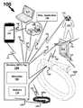
- FIG. 1illustrates an exemplary system of wireless devices including a data-capable band implemented with a wireless enabled cap, according to some examples.
- system 100includes data-capable band (hereinafter “band”) 102 , cap 104 , wireless tag 106 , microchip 108 , antenna 110 , mobile device 112 , laptop 114 , tablet 116 , headset 118 (e.g., worn on a head or an ear of a user 130 ) and miscellaneous application 120 .
- band 102may be implemented as a data-capable strapband as depicted and/or described in the above mentioned Co-Pending U.S. patent applications, which are incorporated herein by reference in their entirety for all purposes.
- Microchip 108may comprise a RF chip, RF circuitry, a chip, a tag, RF tag, a NFC chip, a NFC tag chip, an ASIC, or other device.
- microchip 108may comprise a semiconductor die including analog and/or digital circuitry for RF communications according to one or more wireless protocols and/or standards.
- band 102may be implemented as a wearable data capture device, including one or more sensors (e.g., sensor(s) 418 in FIG. 4 and the like), or a sensor array, (e.g., active and/or passive sensors) for capturing sensor data relating to temperature, environment, time, motion, activity, accelerometry, physiology, medical condition, biometric conditions, and the like.
- sensorse.g., sensor(s) 418 in FIG. 4 and the like
- sensor arraye.g., active and/or passive sensors
- band 102may be configured to collect local sensor data using said sensor array, which may include, without limitation, an accelerometer, an altimeter/barometer, a light/infrared (“IR”) sensor, a pulse/heart rate (“HR”) monitor, an audio sensor (e.g., microphone, transducer, or others), a pedometer, a velocimeter, a global positioning system (GPS) receiver, a location-based service sensor (e.g., sensor for determining location within a cellular or micro-cellular network, which may or may not use GPS or other satellite constellations for fixing a position), a motion detection sensor (e.g., a single or multi-axis accelerometer and/or a gyroscope), an environmental sensor, one or more biometric sensors (e.g., heart rate, respiration, body temperature, GSR, EMG, bioimpedance, arousal of the sympathetic nervous system—SNS, etc.), a chemical sensor, an electrical sensor, or mechanical sensor, and the like
- band 102also may be configured to capture data from distributed sources (e.g., by communicating with mobile computing devices, other bands 102 , mobile communications devices, wireless client devices (e.g., a smartphone or tablet), computers, laptops, tablets, pads, distributed sensors, GPS satellites, or the like) for processing with sensor data.
- Band 102may wirelessly transmit sensor data (e.g., motion signals, biometric signals) to external wireless devices and/or wireless systems (e.g., other bands 102 , wireless client devices, etc.), and may wirelessly receive data including sensor data from external wireless devices and/or wireless systems (e.g., from other bands 102 , wireless client devices, etc.).
- resource 199may be an external system that may include or have access to a data storage system 197 (e.g., a hard drive, SSD, RAID, NAS) and a compute engine 198 (e.g., a PC, a server, laptop, tablet, etc.).
- a data storage system 197e.g., a hard drive, SSD, RAID, NAS
- a compute engine 198e.g., a PC, a server, laptop, tablet, etc.
- device 112 or device 114may be an external system that may include data storage and computing resources that may be accessed by band 102 .
- band 102 and cap 104may be configured to communicate wirelessly 126 with other wireless devices, wireless systems, or applications, including, without limitation, mobile device 112 (e.g., a wireless client device such as a smartphone), laptop 114 , tablet or pad 116 , headset 118 , miscellaneous application 120 , one or more other bands 102 a , resource 199 (e.g., the Cloud or the Internet), and the like.
- mobile device 112e.g., a wireless client device such as a smartphone
- laptop 114e.g., a wireless client device such as a smartphone
- headset 118e.g., headset 118
- miscellaneous application 120e.g., one or more other bands 102 a
- resource 199e.g., the Cloud or the Internet
- cap 104 and/or band ( 102 , 102 a )may wirelessly communicate with other wireless devices or systems using another wireless device (e.g., 112 or 116 ) as an intermediary transceiver (e.g., a RF relay station), such as wireless communication between band/cap ( 102 , 104 ) and resource 199 via device 112 using wireless links 126 and 146 , or wireless communication between band/cap ( 102 , 104 ) and band/cap 102 a / 104 via device 116 using wireless links 126 and 136 .
- another wireless devicee.g., 112 or 116
- an intermediary transceivere.g., a RF relay station
- wireless tag 106may be implemented as a wireless controller configured to exchange data with said other wireless devices, for example, using short-range communication protocols (e.g., Bluetooth® (BT), Bluetooth® Low Energy (BTLE), ultra wideband, near field communication (NFC), or the like) or longer-range communication protocols (e.g., satellite, mobile broadband (e.g., 5G, 4G, 3G, 2G or the like), other cellular networks, GPS, one or more varieties of IEEE 802.x such as 802.11a/b/g/n (WiFi), WiMAX, other wireless local area network (WLAN), and the like).
- short-range communication protocolse.g., Bluetooth® (BT), Bluetooth® Low Energy (BTLE), ultra wideband, near field communication (NFC), or the like
- longer-range communication protocolse.g., satellite, mobile broadband (e.g., 5G, 4G, 3G, 2G or the like), other cellular networks, GPS, one or more varieties of IEEE 802.x such as 802.11a/b
- cap 104may be enabled with near-field communications (NFC) capabilities (e.g., from a NFC chip), and thus may be able to establish a two-way radio communication with another NFC-enabled device through touching the two devices together, or bringing them into close enough proximity to establish an NFC connection (e.g., a few centimeters or other close distance sufficient for establishing an NFC link).
- NFCnear-field communications
- cap 104may include a wireless or NFC tag, card or chip (hereinafter “tag”) 106 , which may be configured to provide stored data, including data stored using microchip 108 , using a radio frequency (RF) field.
- tag 106may include microchip 108 and antenna 110 , which may be electrically coupled to (e.g., able to transfer electrical energy or an electrical signal to and from) each other.
- microchip 108also may be electrically coupled to one or more other components of band 102 .
- wireless tag 106may be implemented as an unpowered NFC tag, which may be powered or activated by coming within a threshold proximity (e.g., a few centimeters or other close distance sufficient for establishing an NFC link) of a powered NFC device (e.g., band 102 , mobile device 112 , laptop 114 , tablet 116 , headset 118 , miscellaneous application 120 , or the like).
- a threshold proximitye.g., a few centimeters or other close distance sufficient for establishing an NFC link
- a powered NFC devicee.g., band 102 , mobile device 112 , laptop 114 , tablet 116 , headset 118 , miscellaneous application 120 , or the like.
- wireless tag 106may take one or more actions including but not limited to provide data, such as a biometric identifier, other identifier, verification information, authentication information, control data to cause an application (e.g., run or operated using mobile device 112 , laptop 114 , tablet 116 , headset 118 , miscellaneous application 120 , or the like) to open, to pair Bluetooth® devices, to sync Bluetooth® devices, to turn on Bluetooth® or WiFi capabilities in band 102 , to accept programming, to accept re-programming, to accept configuration, to accept re-configuration, to accept software updates, to accept operating system (OS) updates, to sync band 102 with an application (e.g., run or operated using mobile device 112 , laptop 114 , tablet 116 , headset 118 , miscellaneous application 120 , or the like), to modify settings on another device, or the like), or other discreet stored data, to one or more of band 102 , mobile device 112 ,
- wireless tag 106may include other wireless controller circuits.
- the quantity, type, function, structure, and configuration of the elements shownmay be varied and are not limited to the examples provided.
- the quantity, type, function, structure, and configuration of the elements shownmay be varied and are not limited to the examples provided.
- microchip 108may be a passive electrical device that may not receive electrical power directly from band 102 or any circuitry or power source(s) in band 102 .
- microchip 108may include circuitry to passively receive electrical power from an external source other than circuitry or power sources in the band 102 .
- the external sourcemay be an externally generated RF signal that is electrically coupled with the microchip 108 through an antenna, such as antenna 110 , for example.
- a device configured for NFCa device configured for very short range (e.g., in near field proximity of a wireless client device(s)) RF communication, or other RF/wirelessly enabled device, may be the source of the externally generated RF signal, for example.
- Microchip 108may be disposed within the housing and configured to electrically communicate stored data in accordance with one or more short-range wireless communication standards and/or protocols. Energy from the externally generated RF signal may be received by the antenna (e.g., 110 ) and electrically coupled with microchip 108 as a signal. Circuitry in the microchip 108 may convert the received signal into electrical power to power the microchip 108 .
- a close or very close proximity(e.g., in a near field proximity) between a device that generates the externally generated RF signal and the antenna may be necessary for a received signal strength (e.g., RSSI) at the antenna to be of sufficient power to generate electricity within microchip 108 when the externally generated RF signal is coupled with the antenna.
- a received signal strengthe.g., RSSI
- the microchipe.g., its antenna 110 or the like
- a threshold proximitye.g., a few centimeters or other close distance sufficient for establishing an NFC link
- a threshold proximitye.g., a few centimeters or other close distance sufficient for establishing an NFC link
- the antenna 110may comprise a flexible printed circuit (FPC) antenna or may be implemented using a conductive ink as described herein (e.g., see 1230 in FIG. 12 ).
- the FPC antennamay include one or more electrically conductive structures and/or patterns formed on a FPC dielectric material or a flux field directional material (FFDM), for example.
- FFDMflux field directional material
- band 102may be implemented with cap 104 , which may be removably coupled to band 102 .
- “coupled”may be used to refer to electrical coupling, physical coupling, or both.
- cap 104may be configured to snap onto and off of an end of band 102 .
- cap 104may be tethered or leashed (not shown) to band 102 such that it may be uncapped, and still remain coupled to band 102 .
- cap 104may be configured to cover a plug (e.g., plug 212 in FIG. 2 , or the like) at an end of band 102 .
- cap 104may include one or more housings and a plate forming a top surface of cap 104 , said plate or top surface of cap 104 configured to receive material, for example, as a printed material deposited in the form of a logo, name or other image or text (see, e.g., plate 204 in FIG. 2 ).
- said plate or top surface of cap 104may be integrally molded as part of an outer housing of cap 104 .
- wireless tag 106may include microchip 108 and antenna 110 .
- microchip 108may be configured to store at least 128 bytes, and up to 2,000 bytes or more, of data, and may be configured to operate at a frequency of 13.56 MHz or 13.6 MHz according to an NFC standard.
- microchip 108may be NFC Forum Type 2 tag compliant, NFC Forum Type 4 tag compliant, or the like.
- Other examplesinclude NFC standards maintained by the NFC Forum of Wakefield, Mass.
- the quantity, type, function, structure, and configuration of the elements shownmay be varied and are not limited to the examples provided.
- FIG. 2illustrates a diagram depicting an exemplary wireless enabled cap for a data-capable band, according to some examples.
- diagram 200includes cap 202 , plate 204 , band 206 , microchip 208 , multi-purpose antenna 210 , plug 212 and plug base 214 .
- cap 202may include an inner housing 216 and an outer housing 218 .
- inner housing 216 and outer housing 218may be integrally molded, for example, to form a single housing. In other examples, they may be molded separately.
- inner housing 216may fit within outer housing 218 .
- inner housing 216may have a cavity (not shown) configured to receive plug 212 , and in some examples, plug base 214 as well.
- an end of housings 216 and 218may have an opening (not shown) leading into said cavity, said opening configured to receive plug 212 .
- plug 212may be coupled to an end of band 206 , for example at plug base 214 , and be configured to send, receive or otherwise transfer data (e.g., sensor data, identification data, verification data, and the like) to one or more other devices (e.g., mobile device 112 , laptop 114 , tablet 116 , headset 118 , miscellaneous application 120 in FIG.
- datae.g., sensor data, identification data, verification data, and the like
- plug 212may be implemented as a connector including but not limited to a TRRS-type, TRS-type or TS-type analog audio plug (e.g., 3.5 mm, 2.5 mm or the like), a Universal Serial Bus (USB) type (e.g., micro USB, mini USB, etc.), or other types of analog or digital plugs (e.g., for audio and/or video), which may be used in connection with firmware and software that allow for the transmission of audio tones to send or receive encoded data, which may be performed using a variety of encoded waveforms and protocols, without limitation.
- TRRS-typeTRS-type or TS-type analog audio plug
- USBUniversal Serial Bus
- analog or digital plugse.g., for audio and/or video
- cap 202 and plate 204may be molded using any type of suitable material, including plastics, thermoplastics, thermoplastic elastomers (TPEs), polymers, elastomers, or any other organic or inorganic material.
- the materialmay be molded to form 202 and/or 204 , for example.
- cap 202 and plate 204may be integrally molded as a monolithic cap.
- microchip 208may be mounted on (e.g., using insert molding, other molding techniques, or the like), embedded within, or otherwise disposed on, (hereinafter collectively “disposed on”) any side or surface (e.g., interior or exterior side) of, or within any wall of, inner housing 216 or outer housing 218 .
- multi-purpose antenna 210may be disposed on plate 204 , which may be configured to cover, or form a top side and surface of, or otherwise couple with, cap 202 .
- multi-purpose antenna 210may be formed using conductive ink embedded, or disposed, onto plate 204 , for example, in the shape of a logo or text (e.g., see 1230 in FIG. 12 ). In this way, multi-purpose antenna 210 may serve decorative, informative, and data exchange purposes.
- conductive inkmay be used to print a company name, a slogan, a product name, a Trademark, a Service Mark, an image, icon, artwork, ASCII characters, text, other stylized logo, or the like, in one or more colors, with the conductive ink also serving as an antenna.
- Plate 204 or some other substratemay be made from and electrically non-conductive material including but not limited to plastic, rubber, silicon, glass, a synthetic material, a composite material, Teflon, PVDF, or the like, just to name a few.
- the conductive ink(e.g., for multi-purpose antenna 210 ) may be printed, screen printed, sprayed, or otherwise formed or deposited on the plate 204 or substrate.
- multi-purpose antenna 210may be electrically coupled to (e.g., able to transfer electrical energy or an electrical signal to and from) microchip 208 , directly or indirectly.
- an antennamay be implemented elsewhere on cap 202 , apart from a logo, either on plate 204 or on a side or surface of cap 202 (see, e.g., antennas 308 - 312 c in FIG. 3 , and the like).
- the quantity, type, function, structure, and configuration of the elements shownmay be varied and are not limited to the examples provided.
- FIG. 3is a diagram depicting exemplary placements of components in a wireless enabled cap for a data-capable band, according to some examples.
- diagram 300includes caps 302 - 306 , antennas 308 - 312 c , microchips 314 - 318 and opening 320 (depicted in dashed line).
- cap 302may include inner housing 302 a and outer housing 302 b
- cap 304may include inner housing 304 a and outer housing 304 b
- cap 306may include inner housing 306 a and outer housing 306 b .
- caps 302 - 306each may include a plate (e.g., plate 204 in FIG. 2 , or the like) configured to fit onto outer housings 302 b - 306 b , and to cover inner housings 302 a - 306 a .
- cap 302may include antenna 308 and microchip 314 disposed on any surface of inner housing 302 a .
- antenna 308 and microchip 314may be disposed on other surfaces (e.g., inner or outer, side or bottom, or the like) of inner housing 302 a .
- antenna 308 and microchip 314may be embedded into a top side, or other side of inner housing 302 a .
- antenna 308may be inserted or otherwise positioned in an opening of inner housing 302 a during a manufacturing step, such as a molding process, for example.
- antenna 308 and microchip 314may be electrically coupled.
- the quantity, type, function, structure, and configuration of the elements shownmay be varied and are not limited to the examples provided.
- cap 304may include opening 320 , which may be configured to open into a cavity configured to receive a plug (e.g., plug 212 in FIG. 2 , and the like).
- cap 304may include antenna 310 embedded into or disposed on (hereinafter “disposed on”) one or more sides (e.g., inner or outer, side, top or bottom, or the like) of outer housing 304 b .
- cap 304also may include microchip 316 disposed on one or more sides (e.g., inner or outer, side, top or bottom, or the like) of inner housing 304 a .
- microchip 316may be disposed on outer housing 304 b , and antenna 310 may be disposed on inner housing 304 a . In some examples, antenna 310 and microchip 316 may be electrically coupled. In other examples, the quantity, type, function, structure, and configuration of the elements shown may be varied and are not limited to the examples provided.
- cap 306may include antennas 312 a - 312 c , disposed on a top surface of inner housing 306 a .
- antennas 312 a - 312 cmay be disposed on a different surface (e.g., inner or outer, side or bottom, or the like) of inner housing 306 a .
- antennas 312 a - 312 cmay be disposed on a side of outer housing 306 b .
- cap 306also may include microchip 318 , disposed on a side (e.g., inner or outer, side, top or bottom, or the like) of outer housing 306 b .
- microchip 318may be disposed on a side of inner housing 306 a .
- antennas 312 a - 312 cmay be electrically coupled to microchip 318 .
- the quantity, type, function, structure, and configuration of the elements shownmay be varied and are not limited to the examples provided.
- microchips 314 - 318each also may be electrically coupled, wired or wirelessly, with one or more components of a band (e.g., band 102 in FIG. 1 , band 206 in FIG. 2 , band 400 in FIG. 4 , or the like).
- electrical contactsmay be disposed in caps 302 - 306 to couple microchips 314 - 318 to a plug that is coupled to a band.
- electrical contactsmay be disposed in caps 302 - 306 to couple microchips 314 - 318 to a circuit (e.g., PCBA, flexible circuit, or the like) implemented in a band.
- microchips 314 - 318may exchange data wirelessly with a band using a short-range communication protocol (e.g., NFC, Bluetooth®, ultra wideband, or the like), for example, with a band including a powered NFC device configured to power, and access the data in, one or more of microchips 314 - 318 when brought into a close or threshold proximity (e.g., ten centimeters or less, or other close distance sufficient for establishing an NFC link).
- a close or threshold proximitye.g., ten centimeters or less, or other close distance sufficient for establishing an NFC link.
- the quantity, type, function, structure, and configuration of the elements shownmay be varied and are not limited to the examples provided.
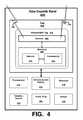
- FIG. 4illustrates an exemplary architecture for a data-capable band implemented with a wireless enabled cap, according to some examples.
- data-capable band (hereinafter “band”) 400includes cap 402 , one or more processors 414 , communication facility 416 , sensor 418 , battery 420 (e.g., a rechargeable battery, Lithium-Ion battery, Nickel-Metal Hydride battery, etc.), audio plug 422 (e.g., TRS, TRRS, USB, micro USB, 3.5 mm plug, 1 ⁇ 4 inch plug, etc.), and vibration source 424 .
- battery 420e.g., a rechargeable battery, Lithium-Ion battery, Nickel-Metal Hydride battery, etc.
- audio plug 422e.g., TRS, TRRS, USB, micro USB, 3.5 mm plug, 1 ⁇ 4 inch plug, etc.
- vibration source 424e.g., vibration source 424 .
- cap 402may include a wireless/NFC tag 404 , which may include antenna 406 and microchip 408 , including memory 410 and one or more processors 412 .
- processor 414may be implemented as part of a printed circuit board assembly (PCBA).
- communication facility 416may be configured to communicate or exchange data with one or more devices, wired or wirelessly (e.g., 126 ), for example, using a communications network (wired and/or wireless router, IEEE 802.11 network, Ethernet network, WiFi network, WiMAX network, Bluetooth network, Ad Hoc WiFi network, etc.).
- communication facility 416may include one or more controllers (e.g., Bluetooth® controller, WiFi controller, mobile broadband controller, and the like) for communicating using short-range or longer range communication protocols, as described herein.
- controllerse.g., Bluetooth® controller, WiFi controller, mobile broadband controller, and the like
- sensor 418may include one or more sensors (e.g., active and/or passive), or a sensor array, for capturing sensor data relating to temperature, environment, time, motion, activity, physiology, medical condition, and the like.
- said sensor arraymay include, without limitation, an accelerometer, an altimeter/barometer, a light/infrared (“IR”) sensor, a pulse/heart rate (“HR”) monitor, an audio sensor (e.g., microphone, transducer, or others), a pedometer, a velocimeter, a global positioning system (GPS) receiver, a location-based service sensor (e.g., sensor for determining location within a cellular or micro-cellular network, which may or may not use GPS or other satellite constellations for fixing a position), a motion detection sensor, an environmental sensor, a chemical sensor, an electrical sensor, or mechanical sensor, and the like, installed, integrated, or otherwise implemented on band 102 .
- GPSglobal positioning system
- cap 402may include a housing (e.g., inner housing 216 and outer housing 218 in FIG. 2 , inner housings 302 a , 304 a and 306 a , and outer housings 302 b , 304 b and 306 b , in FIG. 3 , and the like) configured to cover audio plug 422 .
- processor 412may be configured to process data to be stored in memory 410 , and to be exchanged with other NFC capable devices, for example using antenna 406 .
- antenna 406may be implemented as a multi-purpose antenna.
- memory 410may be configured to store at least 128 bytes, and up to 2,000 bytes or more, of data.
- wireless/NFC tag 404may be configured to exchange data with communication facility 416 , for example, to send data (e.g., biometric identifier, other identifier, verification information, authentication information, control data (e.g., to cause an application to open, to pair band 400 with another Bluetooth® device, to sync band 400 with another Bluetooth® device, to turn on Bluetooth® or WiFi capabilities in band 400 , to sync band 400 with an application on a different device, to modify settings on band 400 , or the like), or other stored data) to other components of band 400 .
- wireless/NFC tag 404may be NFC Forum Type 2 tag compliant, NFC Forum Type 4 tag compliant, or the like.
- band 400may include other components or elements, such as a user interface, a flexible circuit, a notification facility, one or more buttons, and the like, which may not be depicted herein, but are depicted and/or described in the above mentioned Co-Pending U.S. patent applications and/or issued U.S. patents, which are incorporated herein by reference in their entirety for all purposes.
- the quantity, type, function, structure, and configuration of the elements shownmay be varied and are not limited to the examples provided.
- FIG. 5illustrates an exemplary computing platform suitable for a data-capable band implemented with a wireless enabled cap, according to some examples.
- computing platform 500may be used to implement computer programs, applications, methods, processes, algorithms, or other software to perform the above-described techniques.
- Computing platform 500includes a bus 502 or other communication mechanism for communicating information and/or signals, which interconnects subsystems and devices, such as one or more processors 504 , system memory 506 (e.g., RAM, Flash, etc.), storage device 508 (e.g., ROM, etc.), a communication interface 513 (e.g., an Ethernet and/or wireless controller, a Bluetooth controller, etc.) to facilitate communications via a port on communication link 521 to communicate, for example, with a computing device, including mobile computing and/or communication devices with processors and/or wireless communication (e.g., 126 , 136 , 146 ) with one or more wireless devices/systems, and an NFC tag 510 , including antenna 512 and NFC chip 514 , to facilitate direct communication with an NFC-enabled device.
- subsystems and devicessuch as one or more processors 504 , system memory 506 (e.g., RAM, Flash, etc.), storage device 508 (e.g., ROM,
- Processor 504may be implemented with one or more central processing units (“CPUs”), such as those manufactured by Intel® Corporation, or one or more virtual processors, as well as any combination of CPUs and virtual processors.
- Computing platform 500exchanges data representing inputs and outputs via input-and-output (I/O) devices 501 , including, but not limited to, keyboards, mice, touch pad, audio inputs (e.g., speech-to-text devices), user interfaces, displays, monitors, cursors, gesture recognition, image capture device (e.g., video and/or still camera), proximity detection sensors, touch-sensitive displays, touch-screen, LCD, OLED, LED, or other types of displays, speakers, microphones, media players and other I/O-related devices.
- I/Oinput-and-output
- computing platform 500performs specific operations by processor 504 executing one or more sequences of one or more instructions stored in system memory 506 (e.g., a non-transitory computer readable medium such as Flash memory or the like), and computing platform 500 may be implemented in a client-server arrangement, peer-to-peer arrangement, or as any mobile computing device, including smart phones and the like. Such instructions or data may be read into system memory 506 from another non-transitory computer readable medium, such as storage device 508 . In some examples, hard-wired circuitry may be used in place of or in combination with software instructions for implementation. Instructions may be embedded in software or firmware.
- system memory 506e.g., a non-transitory computer readable medium such as Flash memory or the like
- Such instructions or datamay be read into system memory 506 from another non-transitory computer readable medium, such as storage device 508 .
- hard-wired circuitrymay be used in place of or in combination with software instructions for implementation. Instructions may be embedded in software or firmware
- Non-volatile mediaincludes, for example, optical or magnetic disks and the like.
- Volatile mediaincludes dynamic memory, such as system memory 506 .
- non-transitory computer readable mediamay include, for example, floppy disk, flexible disk, hard disk drive (HDD), solid state disk (SSD), magnetic tape, any other magnetic medium, CD-ROM, any other optical medium, punch cards, paper tape, any other physical medium with patterns of holes, RAM, PROM, EPROM, Flash Memory, FLASH-EPROM, any other memory chip or cartridge, or any other medium from which a computer may read. Instructions may further be transmitted or received using a transmission medium.
- the term “transmission medium”may include any tangible or intangible medium that is capable of storing, encoding or carrying instructions for execution by the machine, and includes digital or analog communications signals or other intangible medium to facilitate communication of such instructions.
- Transmission mediaincludes coaxial cables, copper wire, and fiber optics, including wires that comprise bus 502 for transmitting a computer data signal.
- execution of the sequences of instructionsmay be performed by computing platform 500 .
- computing platform 500may be coupled by communication link 521 (e.g., a wired network, such as LAN, PSTN, or any wireless network) to any other processor to perform the sequence of instructions in coordination with (or asynchronous to) one another.
- Communication link 521e.g., a wired network, such as LAN, PSTN, or any wireless network
- Computing platform 500may transmit and receive messages, data, and instructions, including program code (e.g., application code) through communication link 521 and communication interface 513 .
- Received program codemay be executed by processor 504 as it is received, and/or stored in memory 506 or other non-volatile storage for later execution.
- system memory 506may include various modules that include executable instructions to implement functionalities described herein.
- the structures and/or functions of any of the above-described featuresmay be implemented in software, hardware, firmware, circuitry, or any combination thereof.
- the structures and constituent elements above, as well as their functionalitymay be aggregated or combined with one or more other structures or elements. Alternatively, the elements and their functionality may be subdivided into constituent sub-elements, if any.
- at least some of the above-described techniquesmay be implemented using various types of programming or formatting languages, frameworks, syntax, applications, protocols, objects, or techniques.
- at least one of the elements depicted in FIG. 4may represent one or more algorithms.
- at least one of the elementsmay represent a portion of logic including a portion of hardware configured to provide constituent structures and/or functionalities.
- the above-described structures and techniquesmay be implemented using various types of programming or integrated circuit design languages, including but not limited to hardware description languages, such as any register transfer language (“RTL”) configured to design field-programmable gate arrays (“FPGAs”), application-specific integrated circuits (“ASICs”), multi-chip modules, digital circuitry, analog circuitry, mixed-analog-digital circuitry, radio frequency (RF) circuitry, or any other type of integrated circuit.
- RTLregister transfer language
- FPGAsfield-programmable gate arrays
- ASICsapplication-specific integrated circuits
- RFradio frequency
- the term “circuit”may refer, for example, to any system including a number of components through which current flows to perform one or more functions, the components including discrete and complex components.
- discrete componentsinclude transistors, resistors, capacitors, inductors, diodes, and the like
- complex componentsinclude memory, processors, analog circuits, digital circuits, and the like, including field-programmable gate arrays (“FPGAs”), application-specific integrated circuits (“ASICs”). Therefore, a circuit may include a system of electronic components and logic components (e.g., logic configured to execute instructions, such that a group of executable instructions of an algorithm, for example, and, thus, is a component of a circuit).
- logic componentse.g., logic configured to execute instructions, such that a group of executable instructions of an algorithm, for example, and, thus, is a component of a circuit.
- the term “module”may refer, for example, to an algorithm or a portion thereof, and/or logic implemented in either hardware circuitry or software, or a combination thereof (e.g., a module may be implemented as a circuit).
- algorithms and/or the memory in which the algorithms are storedare “components” of a circuit.
- circuitmay also refer, for example, to a system of components, including algorithms. These may be varied and are not limited to the examples or descriptions provided.
- FIG. 6illustrates an exemplary flow for transmitting an instruction to perform an action using a wireless enabled cap, according to some examples.
- flow 600begins with receiving, by a wireless enabled cap, a wireless signal using a multi-purpose antenna ( 602 ).
- said wireless signalmay be a RF signal.
- wireless enabled capmay include one or more housings, and a wireless tag or controller, as described herein.
- said wireless enabled capmay include an NFC tag having a microchip and an antenna.
- said multi-purpose antennamay be implemented to serve multiple functions, including sending and receiving radio signals, as well as decorative or informative functions, where the antenna is formed using electrically conductive ink, as described herein.
- an instructionmay be generated using circuitry implemented in the wireless enabled cap ( 604 ).
- such circuitrymay be implemented as a wireless-to-wired converter.
- said circuitrymay be implemented as part of an NFC tag.
- the instructionmay be responsive to an NFC signal from another NFC-enabled device.
- the instructionmay include data associated with a biometric identifier, other identifier, verification information, authentication information, control data, or other stored data.
- the instructionalso may include logic configured to perform one or more functions, for example, to cause an application to open, to generate a pairing between Bluetooth® devices, to sync Bluetooth® devices, to turn on Bluetooth® or WiFi capabilities in a band, to sync a band with an application on another device, to modify settings on a band or another device, or the like.
- the instructionmay be transmitted using a communication channel, the instruction configured to cause a device to perform an action ( 606 ).
- the communication channelmay be a wired communication channel, for example, using one or more contacts configured to couple to an audio plug or a circuit implemented in a band.
- the communication channelmay be wireless, for example, using a short-range communication protocol, as described herein.
- the above-described processmay be varied in steps, order, function, processes, or other aspects, and is not limited to those shown and described.
- the receiving the wireless signal by the wireless cap using the multipurpose antennamay include the wireless signal coupling with the antenna to generate a signal that is electrically coupled with the microchip 108 to cause the microchip 108 (e.g., the passively powered microchip) to be powered by the signal while the signal is persistent, as was described above.
- the electrical power generated by the wireless signal coupling with the antennamay operate to power the microchip 108 to generate the instruction using circuitry at the stage 604 and/or transmit the instruction at the stage 606 .
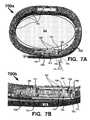
- FIGS. 7A and 7Bwere partial cross-sectional views 700 a and 700 b , respectively, of a data-capable device 702 (e.g., a wearable structure such as a data-capable band, wearable device, a smart watch, etc.) and a wireless enabled cap 704 connected with the device 702 (band 702 hereinafter) are depicted.
- a data-capable device 702e.g., a wearable structure such as a data-capable band, wearable device, a smart watch, etc.
- wireless enabled cap 704may include additional structure and/or components than those described above for wireless enabled cap 104 .
- wireless enabled cap 704may exclude structure and/or components described above for wireless enabled cap 104 .
- a chassis 760 of the data-capable band 702may be configured to connect at least a portion of the band 702 with a body portion 701 (depicted in cross-section) of a user (not shown).
- Body portion 701may include but is not limited to an arm, a leg, a wrist, a neck, an ankle, abdomen, torso, a calf, a thigh, triceps, or bicep, for example.
- Data-capable band 702may be donned on body portion 701 using a variety of methods including but not limited to wrapping or flexing band 702 around a partial and/or full circumference of the body portion 701 , strapping band 702 to the body portion 701 , just to name a few.
- chassis 760may include structures denoted generally as 761 that may include but are not limited to electronic systems (e.g., in FIGS. 4 and 5 ), circuitry, sensors, power sources, and structure that allows band 702 to retain its shape when donned by a user.
- Band 702is a non-limiting example of a device 702 that may be coupled with a wirelessly enabled cap, such as caps 104 , 704 , and other caps described herein, and the present application is not limited to the examples of devices depicted herein.
- Cap 704is depicted mounted to the band 702 . Mounting may be accomplished by inserting plug 212 into a cavity 720 of cap 704 .
- Cap 704may include one or more structures (e.g., 811 ) configured to retain the cap 704 on the plug as will be described below in reference to FIGS. 8A-8B .
- the structuresmay be configured to grip plug base 214 with a force (e.g., a friction force) that retains the cap on the band 702 , but also allows for the cap 704 to be removed when necessary.
- Plug 212may be electrically coupled with one or more systems and/or circuitry in band 702 using a connector portion 708 .
- Cap 704may comprise a variety of materials including but not limited to electrically conductive materials, electrically non-conductive materials, plastics, metals, metal alloys, composites, etc.
- cap 704may include a first material 733 having cavity 720 formed therein to receive plug 212 and having another cavity 740 (depicted inside dashed line) formed therein to receive tag 106 and/or microchip 108 denoted as chip 750 , a second material 731 that may surround at least a portion of the first material 733 , and an antenna 730 which may be positioned between the first 733 and second 731 materials.
- Antenna 730(e.g., antenna 110 ) may be routed around one or more surfaces of the first material 733 and may be coupled with electrical nodes on chip 750 using soldering, crimping, surface mounting, etc.
- Antenna 730may be formed from a variety of materials including but not limited to a flexible printed circuit board, a flexible electrically conductive substrate, an electrically conductive substrate, for example.
- the first material 733 , the second material 731 or bothmay be made from electrically non-conductive materials, such as plastics, rubber, composites, synthetics, organic and/or inorganic materials, or other materials.
- Cap 704may optionally include a structure 735 that may be coupled with the second material 731 (e.g., by glue, adhesives, fastener, etc.). Structure 735 may have a functional purpose (e.g., as an antenna), an esthetic purpose (e.g., a brand logo, to add color(s), a fashionable design, etc.) or both. Orientation of cap 704 relative to band 702 when mounted on the band 702 may be application dependent and is not limited to the examples depicted in FIGS. 7A-7B .
- cap 704may be application dependent and is not limited to the examples depicted in FIGS. 7A-7B .
- Chip 750may comprise a wireless component such as a NFC chip, NFC tag, or the like.
- chip 750may comprise a NTAG203 NFC chip or other device for use in a NFC enabled device, such as cap ( 104 , 704 , 904 ).
- Chip 750may conform to a protocol or standard such as that of the NFC Forum or other NFC standards for wireless devices.
- Chip 750may be an ASIC that is custom designed for an application specific NFC device. Dimensions for chip 750 will be application specific; however, a typical die (e.g., from a semiconductor wafer) for chip 750 may be about 5 mm or less on a side (e.g., 2 mm by 2 mm or less).
- a cavity(e.g., 740 , 940 ) in which the chip 750 is mounted in cap ( 104 , 704 , 904 ) may be dimensioned accordingly to accommodate mounting of the chip 750 in the cavity or other structure in the cap ( 104 , 704 , 904 ) that receives the chip 750 .
- Chip 750may comprise one of the above described chips (e.g., 108 , 208 , 318 , 408 , or 514 ) for a wireless NFC tag (e.g., 510 , 404 , or 106 ).
- the cap 704when mounted or otherwise connected with a device, such as band 702 (see FIG.
- wireless 7Amay wirelessly communicate (e.g., 126 , 136 ) with other wireless devices, wireless client devices, smartphone, tablets, pads, wireless networks (e.g., WiFi, WiMAX, one or more varieties of IEEE 802.x, Bluetooth, Bluetooth Low Energy, NFC, or others, etc.).
- wireless networkse.g., WiFi, WiMAX, one or more varieties of IEEE 802.x, Bluetooth, Bluetooth Low Energy, NFC, or others, etc.
- FIGS. 8A and 8Bdepict profile 800 a and cross-sectional 800 b views, respectively of another example of wireless enabled cap 704 .
- an entrance end of cap 704may include one or more structures 811 configured to engage plug 212 (e.g., grip plug base 214 ) when plug 212 is inserted into cavity 720 .
- a back surface 720 b of cavity 720may be operative to prevent mechanical and/or electrical contact between plug ( 212 , 912 ) and chip 750 and/or antenna 730 .
- Antenna 730(depicted in dashed outline) may be positioned below second material 731 and between first material 733 or embedded in first material 731 as is depicted in greater detail in FIGS. 8B and 8C .
- Antenna 730may be routed over and/or between one or more surfaces of materials 733 and/or 731 .
- antenna 730may be routed over a first portion of first material 733 and over a second portion of first material 733 , with the second portion positioning the antenna 730 for electrical connection with chip 750 in cavity 740 .
- antenna 730may be bent or folded over an edge 821 of the first material 730 to position a portion of antenna 730 on the second portion of the first material 733 .
- Second material 731may include a cavity 841 configured to receive a portion of structure 735 .
- Structure 735may include indicia 835 that may be functional, esthetic or both.
- indicia 835may be a logo, a trademark, artwork, instructions, an image, a name, initials, a nick name, a monogram, a model number, a serial number, etc., just to name a few.
- Materials for 731may include but are not limited to an electrically conductive substrate, an electrically conductive flexible substrate, metal, metal alloys, a plastic substrate having electrically conductive structures, FPCB, and polyimide, for example.
- FIG. 8Ctwo examples of configurations ( 800 c and 800 d ) of antenna 730 embedded in the first material 731 of cap 704 are depicted.
- Configuration 800 ddepicts several different example configurations for the antenna embedded in cap 704 as will be described below.
- antenna 730may be embedded in first material 731 and may span along top and side portions of the first material 731 .
- antenna 730may be embedded in first material 731 and may span along a top portion of the first material 731 (e.g., see antenna 730 which may be embedded in top portion of material 1131 in configuration 1100 a of FIG. 11 ).
- antenna 730may be embedded in first material 731 and may span along another portion of the first material 731 , such as a side portion as depicted by a vertical position of an antenna 730 a along the side portion (e.g., see antenna 730 a which may be embedded in side portion of material 1131 in configuration 1100 a of FIG. 11 ), in contrast to the horizontal position of the antenna 730 along the top portion in configuration 800 d.
- antenna 730may be embedded in the structure 735 as depicted by antenna 730 b .
- antenna 730may be embedded in the first material (e.g., 730 and/or 730 a ) and may also be embedded in the structure 735 as depicted by antenna 730 b in configuration 800 d (e.g., see antennas 730 , 730 a , 730 b which may be embedded in materials 1131 and/or 1135 in configuration 1100 a of FIG. 11 ).
- Antennas( 730 , 730 a , 730 b , 730 c ) may be electrically coupled with chip 750 using any suitable means including soldering, crimping, direct contact of their respective nodes, etc.
- Materials for 731 and/or 735may be selected for properties consistent with reliable RF signal transmission and/or reception for antennas ( 730 , 730 a , 730 b , 730 c ).
- wireless enabled cap 904may include additional structure and/or components than those described above for wireless enabled cap 104 and/or 704 .
- wireless enabled cap 904may exclude structure and/or components described above for wireless enabled cap 104 and/or 704 .
- a first material 933may serve as a foundation (e.g., a mandrel or preform) upon which the antenna 930 may be disposed.
- first material 933may include arcuate surfaces 941 and antenna 930 may be conformally coupled with one or more surfaces of the first material 933 such that antenna 930 conformally covers the one or more surfaces.
- the first material 933may include the cavity 730 through which plug 212 may be inserted 921 to mount the cap 904 to the band ( 102 , 202 , 702 ).
- Antenna 930may be made from a flexible material, such as a flexible printed circuit board material, a flexible electrically conductive material, or other suitable materials.
- Antenna 930may be made from an inflexible material that is shaped (e.g., by pressing, stamping, machining, rolling, or other machine processes) to conform to a shape of first material 933 .
- a portion of antenna 930may be positioned on a back surface 933 b of material 933 to allow that portion of antenna 930 to be electrically coupled with chip 740 in a cavity 940 , as depicted in FIG. 9C .
- the back surface 933 bmay include a groove, indentation, recess, depression, or the like, denoted as 933 g , in which the portion of antenna 930 may be disposed in when positioned on the back surface 933 b.
- Antenna 930may include a structure 951 operative to receive the chip 750 .
- Structure 951may be formed from the same material as antenna 930 or may be made from a different material (e.g., an electrically insulating material) that is connected with antenna 930 .
- Structure 951may be operative to align chip 750 and antenna 930 with each other to facilitate electrical connection (e.g., via soldering, etc.) of electrically conductive nodes on chip 750 with electrically conductive nodes on antenna 930 .
- the nodesmay comprise pads, bumps, balls, or other electrically conductive structures.
- Structure 951may be configured to fit inside cavity 940 when antenna 930 is positioned on first material 933 . In FIG.
- the cavity 720 through which plug 212 may be inserted 921 to mount the cap 904 to the band ( 102 , 202 , 702 )may be configured to receive a plug, connector, or the like having a different configuration than plug 212 , such as a male or female USB connector or plug for example.
- a male micro USB plug 912may be inserted 921 into cavity 720 to mount the cap 904 to the band ( 102 , 202 , 702 ).
- First material 933may be formed to include the cavity 720 having a shape configured to receive a profile of the plug 912 .
- Suitable electrical connections with circuitry and systems in band ( 102 , 202 , 702 )may be made by electrically coupling node 912 c of plug 912 with the circuitry and/or systems using wire, PCB traces, busses, or other types of electrically conductive structures.
- Other types of plugs and/or connectorsmay be used and the foregoing are non-limiting examples.
- antenna 930may be formed from a flexible electrically conductive substrate such as a flexible printed circuit board (FPCB), where all or a portion of the substrate may be electrically conductive.
- the substrate for antenna 930may be cut, punched, sawed, cast or otherwise formed to the desired shape.
- a portion of antenna 930(denoted as 1030 in FIG.
- Antenna 930may include portions 1041 that are arcuate and/or include bends, folds, or non-planar shapes or contours, for example.
- FIG. 10Bdepicts a cross-sectional profile view of the antenna structure 930 for a wireless enabled cap 904 and illustrates in greater detail the portion 1030 and its associated structure 951 and cavity 940 in which chip 750 is disposed.
- Structures 951may be made from the same or different materials than antenna 930 and may be formed in a material of the antenna 930 or may be separately formed and mounted to the antenna 930 using adhesives, fasteners, glue, welds, etc., just to name a few.
- FIG. 10Cdepicts a plurality of different views of an antenna structure 930 for a wireless enabled cap 904 .
- the various shapes for antenna 930may be formed by pressing, stamping, machining, rolling, vacuum forming, heating, or other machine processes.
- FIG. 10Ddepicts a plan view of an electrically conductive substrate that may be used as a starting material for an antenna structure 930 for a wireless enabled cap 904 .
- the starting materialmay comprise a substrate or sheet of an electrically conductive material (e.g., stainless steel or other metal and metal alloys) that is formed to a desired shape such as that depicted in the plan view of FIG. 10D , and then the above mentioned processes may be used to fashion the antenna 930 into its desired final shape.
- an electrically conductive materiale.g., stainless steel or other metal and metal alloys
- first material 933may serve as a mandrel or preform over which the antenna may be formed.
- the starting materialmay not include the structures 951 , and those structures may be later added as described above.
- the starting materialmay not necessarily be an electrically conductive material or only portions of the starting material may be electrically conductive, such as the traces on a PCB or flexible PC board.
- the starting materialmay be an electrically non-conductive material or substrate (e.g., plastic, glass, dielectric material) upon which an electrically conductive material is applied or otherwise deposited or formed (e.g., via printing silk screening, screen printing, etc.) to create an electrically conductive medium for antenna 930 , such as electrically conductive inks, paints, dyes, particles, graphene, nano-particles, for example.
- an electrically conductive medium for antenna 930such as electrically conductive inks, paints, dyes, particles, graphene, nano-particles, for example.
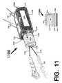
- a RF isolation structure 1150may be positioned in a cavity 1130 formed in a material 1131 of cap 704 .
- the RF isolation structure 1150may include a cavity 1120 formed therein and operative to receive at least a portion of the plug 212 or 912 by insertion 1121 of the plug into the cavity 1120 , for example.
- plug 212comprises a TRS, TRRS, a 2.5 mm audio plug or a 3.5 mm audio plug
- the cavity 1120 , and optionally cavity 1130may be sized accordingly to allow insertion of the plug 212 .
- cavity 1120may be sized accordingly to allow insertion of other types of plugs, such as the plug 912 (e.g., USB, micro USB, mini USB, Lightning® plug, RJ-45 plug, etc.), for example.
- plug 912e.g., USB, micro USB, mini USB, Lightning® plug, RJ-45 plug, etc.
- RF isolation structure 1150may comprise a ferrite coil, a ferrite core, tape wound core, or other type of RF isolation devices (e.g., made from high magnetic permeability and low electrical conductivity materials) operative to isolate antenna 730 and/or improve RF performance of the antenna 930 and/or chip 750 .
- metallic structurese.g., plugs 212 , 912
- other structures in close proximity of antenna 730may interfere with RF signal reception by antenna 730 .
- antenna 730depicted in dashed line, may be positioned below (e.g., see 730 in FIGS.
- An antenna 730 cmay be positioned on the material 1135 as depicted in example 1100 a of FIG. 11 .
- Antenna 730 cmay comprise an electrically conductive material connected with material 1135 or applied/deposited/formed on material 1135 (e.g., using a conductive ink or the like).
- RF isolation structure 1150may isolate one or more antennas (e.g., 730 , 730 a , 730 b ) from other structures such as a second material 1135 that may be functional or non-functional, and/or the plug ( 212 , 912 ), for example.
- Second material 1135may be made from a different material than first material 1131 .
- Second material 1135may be electrically conductive or electrically non-conductive.
- the second materialmay comprise a plastic or other electrically non-conductive material and may be used for an esthetic purpose or include indicia, a logo, a trademark, artwork, instructions, an image, a name, initials, a nick name, a monogram, a model number, a serial number, etc., just to name a few.
- second materialmay be selected to provide RF isolation of antenna 730 .
- the cap 704may have a different shape and/or configuration than depicted in the non-limiting example of FIG. 11 .
- structure 1135may be made from a material suitable for embedding the antenna (e.g., antenna 730 b ) in the structure 1135 as depicted in example configuration 1100 a .
- the cap 704when mounted or otherwise connected with a device, such as band 702 (see FIG. 7A ) for example, may wirelessly communicate (e.g., 126 , 136 ) with other wireless devices, wireless client devices, smartphone, tablets, pads, wireless networks (e.g., WiFi, WiMAX, one or more varieties of IEEE 802.x, Bluetooth, Bluetooth Low Energy, NFC, or others, etc.).
- examples 1200 a - 1200 ddepict an antenna 1230 that may be printed, deposited, screen printed, silk screened, or otherwise formed on an electrically non-conductive structure or surface, such as material 1235 , for example, using an electrically conductive ink, paste, dye, plastic, or other suitable materials.
- a surface 1235 s of material 1235may have a logo or other design formed on it using any number of processes, such as those described above.
- the logo antenna 1230may be electrically coupled with chip 750 (not shown) using any suitable electrically conductive structure such as wire, conductive traces, etc.
- material 1235may be coupled (e.g., using glue, press fitting, adhesive, fastener, welding, etc.) with material 1231 to form cap 704 , which may be operative to wirelessly communicate ( 126 , 136 ) as described above.
- cap 704may include the logo antenna 1230 , another antenna 1230 a , or both.
- Antenna 1230 amay be a flexible PC board, or some other electrically conductive substrate that is electrically coupled with chip 750 (not shown) and positioned on a structure 1241 , for example. Either one or both of the antennas 1230 , 1230 a , may be used for the aforementioned wireless communications ( 126 , 136 ).
- the components of example 1200 cmay be coupled to form cap 704 .
- Antenna 1230need not be a logo and may comprise any form or design that may be printed or otherwise formed on material 1235 .
- Antenna 1230may comprise a plurality of separate antennas or discrete antennas that are formed on 1235 , with each antenna electrically coupled with chip 750 . In other examples, a sub-set of the plurality of separate antennas or discrete antennas that comprise 730 are electrically coupled with chip 750 .
- the housing of the cap as described hereinmay be a body or other structure operative to be gripped by the fingers or digits of a user's hand to facilitate mounting and un-mounting of the cap from the plug (e.g., 212 , 912 ) of the device (e.g., 702 ).
- the housing of the cap as described hereinmay include structures operative to facilitate gripping of the cap by the user, such as silicone, ridges, grooves, knurling, or other materials or structures that may provide grip, traction, etc.
Landscapes
- Engineering & Computer Science (AREA)
- Signal Processing (AREA)
- Computer Networks & Wireless Communication (AREA)
- Computer Hardware Design (AREA)
- Theoretical Computer Science (AREA)
- Human Computer Interaction (AREA)
- Physics & Mathematics (AREA)
- General Engineering & Computer Science (AREA)
- General Physics & Mathematics (AREA)
- User Interface Of Digital Computer (AREA)
- Arrangements For Transmission Of Measured Signals (AREA)
Abstract
Description
Claims (20)
Priority Applications (2)
| Application Number | Priority Date | Filing Date | Title |
|---|---|---|---|
| US14/181,595US9258670B2 (en) | 2011-06-10 | 2014-02-14 | Wireless enabled cap for a data-capable device |
| PCT/US2015/016232WO2015123697A2 (en) | 2011-06-10 | 2015-02-17 | Wireless enabled cap for a data-capable device |
Applications Claiming Priority (8)
| Application Number | Priority Date | Filing Date | Title |
|---|---|---|---|
| US13/158,372US20120313272A1 (en) | 2011-06-10 | 2011-06-10 | Component protective overmolding |
| US13/180,320US8793522B2 (en) | 2011-06-11 | 2011-07-11 | Power management in a data-capable strapband |
| US13/181,495US20120316932A1 (en) | 2011-06-10 | 2011-07-12 | Wellness application for data-capable band |
| US13/492,857US20130176142A1 (en) | 2011-06-10 | 2012-06-09 | Data-capable strapband |
| US13/802,409US20140089672A1 (en) | 2012-09-25 | 2013-03-13 | Wearable device and method to generate biometric identifier for authentication using near-field communications |
| US13/952,532US10218063B2 (en) | 2013-03-13 | 2013-07-26 | Radio signal pickup from an electrically conductive substrate utilizing passive slits |
| US14/144,517US9294869B2 (en) | 2013-03-13 | 2013-12-30 | Methods, systems and apparatus to affect RF transmission from a non-linked wireless client |
| US14/181,595US9258670B2 (en) | 2011-06-10 | 2014-02-14 | Wireless enabled cap for a data-capable device |
Publications (2)
| Publication Number | Publication Date |
|---|---|
| US20150237461A1 US20150237461A1 (en) | 2015-08-20 |
| US9258670B2true US9258670B2 (en) | 2016-02-09 |
Family
ID=53801753
Family Applications (1)
| Application Number | Title | Priority Date | Filing Date |
|---|---|---|---|
| US14/181,595Expired - Fee RelatedUS9258670B2 (en) | 2011-06-10 | 2014-02-14 | Wireless enabled cap for a data-capable device |
Country Status (2)
| Country | Link |
|---|---|
| US (1) | US9258670B2 (en) |
| WO (1) | WO2015123697A2 (en) |
Cited By (15)
| Publication number | Priority date | Publication date | Assignee | Title |
|---|---|---|---|---|
| US9926953B2 (en) | 2013-03-15 | 2018-03-27 | Apple Inc. | Attachment apparatuses and associated methods of use and manufacture |
| US10064460B2 (en) | 2015-09-30 | 2018-09-04 | Apple Inc. | Frictional stabilization of band and securement mechanism |
| US10149518B1 (en) | 2016-08-08 | 2018-12-11 | Apple Inc. | Clasp assembly for a wearable device |
| US10188890B2 (en) | 2013-12-26 | 2019-01-29 | Icon Health & Fitness, Inc. | Magnetic resistance mechanism in a cable machine |
| US10219591B2 (en) | 2016-03-21 | 2019-03-05 | Apple Inc. | Attachment system for an electronic device |
| US10220259B2 (en) | 2012-01-05 | 2019-03-05 | Icon Health & Fitness, Inc. | System and method for controlling an exercise device |
| US10226396B2 (en) | 2014-06-20 | 2019-03-12 | Icon Health & Fitness, Inc. | Post workout massage device |
| US10272317B2 (en) | 2016-03-18 | 2019-04-30 | Icon Health & Fitness, Inc. | Lighted pace feature in a treadmill |
| US10279212B2 (en) | 2013-03-14 | 2019-05-07 | Icon Health & Fitness, Inc. | Strength training apparatus with flywheel and related methods |
| US10391361B2 (en) | 2015-02-27 | 2019-08-27 | Icon Health & Fitness, Inc. | Simulating real-world terrain on an exercise device |
| US10426989B2 (en) | 2014-06-09 | 2019-10-01 | Icon Health & Fitness, Inc. | Cable system incorporated into a treadmill |
| US10433612B2 (en) | 2014-03-10 | 2019-10-08 | Icon Health & Fitness, Inc. | Pressure sensor to quantify work |
| US10493349B2 (en) | 2016-03-18 | 2019-12-03 | Icon Health & Fitness, Inc. | Display on exercise device |
| US10625137B2 (en) | 2016-03-18 | 2020-04-21 | Icon Health & Fitness, Inc. | Coordinated displays in an exercise device |
| US10671705B2 (en) | 2016-09-28 | 2020-06-02 | Icon Health & Fitness, Inc. | Customizing recipe recommendations |
Families Citing this family (14)
| Publication number | Priority date | Publication date | Assignee | Title |
|---|---|---|---|---|
| EP2915502B1 (en)* | 2014-03-06 | 2019-11-20 | W & H Dentalwerk Bürmoos GmbH | Medical, in particular dental system |
| USD794013S1 (en)* | 2014-09-19 | 2017-08-08 | Samsung Electronics Co., Ltd. | Body-worn portable electronic device |
| US10032369B2 (en)* | 2015-01-15 | 2018-07-24 | Magna Electronics Inc. | Vehicle vision system with traffic monitoring and alert |
| WO2016209245A1 (en)* | 2015-06-25 | 2016-12-29 | Intel IP Corporation | Vertical inductor for wlcsp |
| US20180310360A1 (en)* | 2015-07-23 | 2018-10-25 | Vorbeck Materials Corp. | Wearable wireless access point |
| US10540482B2 (en)* | 2016-07-07 | 2020-01-21 | The Florida International University Board Of Trustees | NFC tag reader for patient medication monitoring |
| WO2018022063A1 (en)* | 2016-07-28 | 2018-02-01 | Halliburton Energy Services, Inc. | Real-time plug tracking with fiber optics |
| US10448831B2 (en)* | 2017-03-31 | 2019-10-22 | BraveHeart Wireless Inc. | Wearable sensor |
| KR102275564B1 (en)* | 2017-04-14 | 2021-07-12 | 삼성전자주식회사 | Electronic device and method for transmitting and receiving authentification information in electronic device |
| CN108489556B (en)* | 2018-06-05 | 2024-05-28 | 潍坊浩森智能科技有限公司 | Combined heart rate module |
| US11477736B1 (en) | 2020-06-05 | 2022-10-18 | Amazon Technologies, Inc. | Wearable device battery conservation |
| US12174660B2 (en) | 2020-06-11 | 2024-12-24 | Apple Inc. | Electronic device |
| US11573599B2 (en)* | 2020-06-11 | 2023-02-07 | Apple Inc. | Electrical connectors for electronic devices |
| US11785449B2 (en)* | 2021-09-30 | 2023-10-10 | Visa International Service Association | Secure on-demand ultra-wideband communication channels systems and methods |
Citations (175)
| Publication number | Priority date | Publication date | Assignee | Title |
|---|---|---|---|---|
| US4788627A (en) | 1986-06-06 | 1988-11-29 | Tektronix, Inc. | Heat sink device using composite metal alloy |
| US4819860A (en) | 1986-01-09 | 1989-04-11 | Lloyd D. Lillie | Wrist-mounted vital functions monitor and emergency locator |
| US5019673A (en) | 1990-08-22 | 1991-05-28 | Motorola, Inc. | Flip-chip package for integrated circuits |
| US5246643A (en) | 1990-08-31 | 1993-09-21 | Fanuc Ltd | Discrimination method for maintenance timing for injection molding machines |
| US5426130A (en) | 1991-02-15 | 1995-06-20 | Nd Industries, Inc. | Adhesive system |
| US5692501A (en) | 1993-09-20 | 1997-12-02 | Minturn; Paul | Scientific wellness personal/clinical/laboratory assessments, profile and health risk managment system with insurability rankings on cross-correlated 10-point optical health/fitness/wellness scales |
| US5924979A (en) | 1996-02-09 | 1999-07-20 | Nellcor Puritan Bennett Incorporated | Medical diagnostic apparatus with sleep mode |
| US5974262A (en) | 1997-08-15 | 1999-10-26 | Fuller Research Corporation | System for generating output based on involuntary and voluntary user input without providing output information to induce user to alter involuntary input |
| US6139494A (en) | 1997-10-15 | 2000-10-31 | Health Informatics Tools | Method and apparatus for an integrated clinical tele-informatics system |
| US6156461A (en) | 1997-01-21 | 2000-12-05 | International Business Machines Corporation | Method for repair of photomasks |
| USD439981S1 (en) | 2000-08-09 | 2001-04-03 | Bodymedia, Inc. | Armband with physiological monitoring system |
| US6246900B1 (en) | 1995-05-04 | 2001-06-12 | Sherwood Services Ag | Head band for frameless stereotactic registration |
| US20010004234A1 (en) | 1998-10-27 | 2001-06-21 | Petelenz Tomasz J. | Elderly fall monitoring method and device |
| US6254815B1 (en) | 1994-07-29 | 2001-07-03 | Motorola, Inc. | Molded packaging method for a sensing die having a pressure sensing diaphragm |
| US20010037179A1 (en) | 1994-11-21 | 2001-11-01 | Vock Curtis A. | Systems and methods for determining energy experienced by a user and associated with activity |
| USD451604S1 (en) | 2000-09-25 | 2001-12-04 | Bodymedia, Inc. | Vest having physiological monitoring system |
| WO2002000111A1 (en) | 2000-06-23 | 2002-01-03 | Bodymedia, Inc. | System for monitoring health, wellness and fitness |
| US20020019584A1 (en) | 2000-03-01 | 2002-02-14 | Schulze Arthur E. | Wireless internet bio-telemetry monitoring system and interface |
| JP2002051105A (en) | 2000-08-01 | 2002-02-15 | Nec Commun Syst Ltd | Communication device |
| US6356940B1 (en) | 1999-05-26 | 2002-03-12 | Brian Robert Short | Method and system of electronically logging remote user dietary information, and generating and automatically sending suggested dietary modifications |
| US20020068873A1 (en) | 2000-10-06 | 2002-06-06 | Polar Electro Oy. | Wrist-worn device |
| US20020074877A1 (en) | 2000-12-19 | 2002-06-20 | Samsung Electro-Mechanics Co., Ltd. | Flat-typed vibration motor |
| USD460971S1 (en) | 2001-06-21 | 2002-07-30 | Bodymedia, Inc. | Docking cradle for an electronic device |
| US20020143491A1 (en) | 2000-08-18 | 2002-10-03 | Scherzinger Bruno M. | Pedometer navigator system |
| US20020145571A1 (en)* | 2001-04-10 | 2002-10-10 | Troy Hulick | Frame for a handheld computer |
| WO2001096986A8 (en) | 2000-06-16 | 2002-10-24 | Bodymedia Inc | System for monitoring health, wellness and fitness |
| US6486801B1 (en) | 1993-05-18 | 2002-11-26 | Arrivalstar, Inc. | Base station apparatus and method for monitoring travel of a mobile vehicle |
| US20020183646A1 (en) | 2001-03-30 | 2002-12-05 | Stivoric John M. | System for monitoring health, wellness and fitness having a method and apparatus for improved measurement of heat flow |
| US6527711B1 (en) | 1999-10-18 | 2003-03-04 | Bodymedia, Inc. | Wearable human physiological data sensors and reporting system therefor |
| US20030046228A1 (en) | 2001-08-28 | 2003-03-06 | Jean-Marc Berney | User-wearable functional jewelry with biometrics and smartcard to remotely sign and/or authenticate to e-services |
| US20030130595A1 (en) | 2001-08-13 | 2003-07-10 | Mault James R. | Health improvement systems and methods |
| US20030137588A1 (en)* | 2002-01-23 | 2003-07-24 | Guan-Wu Wang | Wireless camera system |
| US6605038B1 (en) | 2000-06-16 | 2003-08-12 | Bodymedia, Inc. | System for monitoring health, wellness and fitness |
| US6665174B1 (en) | 1999-05-20 | 2003-12-16 | Testo Ag | Control and display device |
| WO2003015005A3 (en) | 2000-06-16 | 2003-12-18 | Bodymedia Inc | Apparatus for monitoring health, wellness and fitness |
| US20030236474A1 (en) | 2002-06-24 | 2003-12-25 | Balbir Singh | Seizure and movement monitoring |
| CA2496579A1 (en) | 2002-08-22 | 2004-03-04 | Bodymedia, Inc. | Apparatus for detecting human physiological and contextual information |
| US6714859B2 (en) | 1993-05-18 | 2004-03-30 | Arrivalstar, Inc. | System and method for an advance notification system for monitoring and reporting proximity of a vehicle |
| US20040147818A1 (en) | 2002-11-18 | 2004-07-29 | Andrew Levy | Portable system for monitoring and processing patient parameters in multiple oprational modes |
| US20040152957A1 (en) | 2000-06-16 | 2004-08-05 | John Stivoric | Apparatus for detecting, receiving, deriving and displaying human physiological and contextual information |
| US20040167409A1 (en) | 2003-01-15 | 2004-08-26 | Salutron, Inc. | Ultrasonic monitor for measuring heart and pulse rates |
| US20050113650A1 (en) | 2000-06-16 | 2005-05-26 | Christopher Pacione | System for monitoring and managing body weight and other physiological conditions including iterative and personalized planning, intervention and reporting capability |
| US6904359B2 (en) | 1993-05-18 | 2005-06-07 | Arrivalstar, Inc. | Notification systems and methods with user-definable notifications based upon occurance of events |
| US20050140005A1 (en) | 2003-12-31 | 2005-06-30 | Advanced Semiconductor Engineering Inc. | Chip package structure |
| US6952645B1 (en) | 1997-03-10 | 2005-10-04 | Arrivalstar, Inc. | System and method for activation of an advance notification system for monitoring and reporting status of vehicle travel |
| WO2005092177A1 (en) | 2004-03-22 | 2005-10-06 | Bodymedia, Inc. | Non-invasive temperature monitoring device |
| US6984886B2 (en) | 2000-03-02 | 2006-01-10 | Micron Technology, Inc. | System-on-a-chip with multi-layered metallized through-hole interconnection |
| US20060065645A1 (en) | 2004-09-27 | 2006-03-30 | Nobuaki Nakasu | Apparatus for repairing circuit pattern and method for manufacturing display apparatus using the same |
| US20060074279A1 (en) | 2004-09-29 | 2006-04-06 | Evgeny Brover | Interactive dieting and exercise system |
| US20060079740A1 (en) | 2000-05-15 | 2006-04-13 | Silver James H | Sensors for detecting substances indicative of stroke, ischemia, or myocardial infarction |
| US7030781B2 (en) | 1993-05-18 | 2006-04-18 | Arrivalstar, Inc. | Notification system and method that informs a party of vehicle delay |
| US20060122474A1 (en) | 2000-06-16 | 2006-06-08 | Bodymedia, Inc. | Apparatus for monitoring health, wellness and fitness |
| US7060216B2 (en) | 2001-05-11 | 2006-06-13 | Melexis, Nv | Tire pressure sensors and methods of making the same |
| US20060132477A1 (en) | 2004-12-17 | 2006-06-22 | Eastman Kodak Company | Methods for making display |
| US7101752B2 (en) | 2003-03-24 | 2006-09-05 | Samsung Electronics Co., Ltd. | Semiconductor process for removing defects due to edge chips of a semiconductor wafer and semiconductor device fabricated thereby |
| US20060237252A1 (en) | 2005-04-25 | 2006-10-26 | Mobley Larry J | Vehicle ignition interlock systems having transdermal alcohol sensor |
| US20070027370A1 (en) | 2004-07-13 | 2007-02-01 | Brauker James H | Analyte sensor |
| JP2007050091A (en) | 2005-08-18 | 2007-03-01 | Yamagishi Kogyo:Kk | Deodorizing and sterilizing apparatus |
| US7196972B2 (en) | 2004-07-02 | 2007-03-27 | Theresa Ann Pitocco | Mediwatch |
| US20070072156A1 (en) | 2005-08-05 | 2007-03-29 | Abk Ventures | Lifestyle coach behavior modification system |
| US20070105404A1 (en) | 2005-07-27 | 2007-05-10 | Physical Optics Corporation | Electrical connector configured as a fastening element |
| US20070185391A1 (en) | 2005-12-22 | 2007-08-09 | Morgan Timothy M | Home diagnostic system |
| US20070186429A1 (en) | 2004-03-30 | 2007-08-16 | Commissariat A L'energie Atomique | Method and Device for Determining a Person's Motions |
| US20070197878A1 (en) | 2004-07-09 | 2007-08-23 | Dror Shklarski | Wearable device, system and method for monitoring physiological and/or environmental parameters |
| US7276802B2 (en) | 2002-04-15 | 2007-10-02 | Micron Technology, Inc. | Semiconductor integrated circuit package having electrically disconnected solder balls for mounting |
| US20070254137A1 (en) | 2004-08-13 | 2007-11-01 | Kerafol Keramische Folien Gmbh | Thermally Conducting Multi-Layer Film |
| US20070253602A1 (en) | 2006-04-27 | 2007-11-01 | Seiko Epson Corporation | Biometric data acquisition device, biometric data acquisition method and biometric authentication device |
| US7306567B2 (en) | 2004-01-09 | 2007-12-11 | Loree Iv Leonor F | Easy wake wrist watch |
| US20070296571A1 (en) | 2006-06-13 | 2007-12-27 | Kolen Paul T | Motion sensing in a wireless rf network |
| US20080004904A1 (en) | 2006-06-30 | 2008-01-03 | Tran Bao Q | Systems and methods for providing interoperability among healthcare devices |
| US20080032119A1 (en) | 2004-09-03 | 2008-02-07 | Karl-Andreas Feldhahn | Plastics For Medical Technical Devices |
| US20080040615A1 (en) | 2006-06-30 | 2008-02-14 | Electronic Plastics, Llc | Biometric embedded device |
| US7336187B2 (en) | 2002-10-18 | 2008-02-26 | The Trustees Of Boston University | Patient activity monitor |
| US20080055074A1 (en) | 2006-04-28 | 2008-03-06 | The Johns Hopkins University | Sensor-based Adaptive Wearable Devices and Methods |
| US7343260B1 (en) | 2005-06-30 | 2008-03-11 | Fullpower, Inc. | Method and apparatus to provide an interface to obtain data from a real-time monitor |
| US20080091089A1 (en) | 2006-10-12 | 2008-04-17 | Kenneth Shane Guillory | Single use, self-contained surface physiological monitor |
| US7364445B1 (en) | 2007-04-13 | 2008-04-29 | Super Talent Electronics, Inc. | USB flash device with rubber cover |
| US20080154098A1 (en) | 2006-12-20 | 2008-06-26 | Margaret Morris | Apparatus for monitoring physiological, activity, and environmental data |
| US20080167535A1 (en) | 2002-08-22 | 2008-07-10 | Stivoric John M | Devices and systems for contextual and physiological-based reporting, entertainment, control of other devices, health assessment and therapy |
| US20080176655A1 (en) | 2007-01-19 | 2008-07-24 | James Terry L | System and Method for Implementing an Interactive Online Community Utilizing an Activity Monitor |
| US20080183388A1 (en) | 2007-01-23 | 2008-07-31 | Alan Goodrich | Unobtrusive system and method for monitoring the physiological condition of a target user of a vehicle |
| US20080194928A1 (en) | 2007-01-05 | 2008-08-14 | Jadran Bandic | System, device, and method for dermal imaging |
| WO2008101248A2 (en) | 2007-02-16 | 2008-08-21 | Bodymedia, Inc. | Systems and methods for understanding and applying the physiological and contextual life patterns of an individual or set of individuals |
| US20080208015A1 (en) | 2007-02-09 | 2008-08-28 | Morris Margaret E | System, apparatus and method for real-time health feedback on a mobile device based on physiological, contextual and self-monitored indicators of mental and physical health states |
| US20080216171A1 (en) | 2007-02-14 | 2008-09-04 | Sony Corporation | Wearable device, authentication method, and recording medium |
| US20080255979A1 (en) | 1999-03-09 | 2008-10-16 | Stuart Slutzky | Wellness program management and integration with payroll vendor systems |
| US7457719B1 (en) | 2006-11-21 | 2008-11-25 | Fullpower Technologies, Inc. | Rotational insensitivity using gravity-based adjustment |
| US20090019374A1 (en) | 2006-02-18 | 2009-01-15 | James D. Logan | Methods and apparatus for creating, combining, distributing and reproducing program content for groups of participating users |
| IL160079A (en) | 2001-08-06 | 2009-02-11 | Bodymedia Inc | Apparatus for monitoring health, wellness and fitness |
| US7502643B2 (en) | 2003-09-12 | 2009-03-10 | Bodymedia, Inc. | Method and apparatus for measuring heart related parameters |
| US20090076343A1 (en) | 2007-09-14 | 2009-03-19 | Corventis, Inc. | Energy Management for Adherent Patient Monitor |
| US20090072955A1 (en) | 2007-09-17 | 2009-03-19 | Patrick Kearney Cary | Wearable coin-sized sensory devices, and related systems and methods, providing immediate wireless notification of activities on separate electronic devices |
| US20090077849A1 (en) | 2007-09-26 | 2009-03-26 | Glass Jr Geoffrey M | Molded sign frame assembly |
| US20090112626A1 (en) | 2007-10-30 | 2009-04-30 | Cary Talbot | Remote wireless monitoring, processing, and communication of patient data |
| US20090118100A1 (en) | 2007-11-02 | 2009-05-07 | Microsoft Corporation | Mobile exercise enhancement with virtual competition |
| US20090131759A1 (en) | 2003-11-04 | 2009-05-21 | Nathaniel Sims | Life sign detection and health state assessment system |
| US20090150178A1 (en) | 2007-12-05 | 2009-06-11 | Rick Douglas Sutton | Method And System For Tracking Physical Metrics In A Social Commerce System |
| US20090146947A1 (en) | 2007-12-07 | 2009-06-11 | James Ng | Universal wearable input and authentication device |
| US20090163774A1 (en) | 2007-12-20 | 2009-06-25 | Sudeesh Thatha | Managment and Diagnostic System for Patient Monitoring and Symptom Analysis |
| US20090192362A1 (en) | 2008-01-24 | 2009-07-30 | Sweeney Robert J | System And Method For Corroborating Transitory Changes In Wellness Status Against A Patient Population |
| US20090208756A1 (en) | 2006-10-31 | 2009-08-20 | Fujitsu Limited | Housing for electronic equipment and manufacturing method thereof |
| US20090218725A1 (en) | 2008-02-29 | 2009-09-03 | Symbol Technologies, Inc. | Injection molded paneled mobile device enclosure |
| US20090264714A1 (en) | 2006-05-18 | 2009-10-22 | Chang-An Chou | Non-invasive vital sign monitoring method, apparatus and system |
| US20090265183A1 (en) | 2008-04-22 | 2009-10-22 | Alan Pollard | Method of managing a wellness programme and a system therefor |
| US20090292180A1 (en) | 2006-04-18 | 2009-11-26 | Susan Mirow | Method and Apparatus for Analysis of Psychiatric and Physical Conditions |
| US20090311976A1 (en)* | 2008-06-17 | 2009-12-17 | Vanderaa Joel D | Form factor and electromagnetic interference protection for process device wireless adapters |
| US20090319347A1 (en) | 2006-07-12 | 2009-12-24 | Henry Albrecht | Systems and methods for a holistic well-being assessment |
| US20090319221A1 (en) | 2008-06-24 | 2009-12-24 | Philippe Kahn | Program Setting Adjustments Based on Activity Identification |
| US20100004947A1 (en) | 2008-07-01 | 2010-01-07 | Michael Nadeau | System and Method for Providing Health Management Services to a Population of Members |
| US7647196B2 (en) | 2007-08-08 | 2010-01-12 | Dp Technologies, Inc. | Human activity monitoring device with distance calculation |
| US7647195B1 (en) | 2006-07-11 | 2010-01-12 | Dp Technologies, Inc. | Method and apparatus for a virtual accelerometer system |
| US7653508B1 (en) | 2006-12-22 | 2010-01-26 | Dp Technologies, Inc. | Human activity monitoring device |
| US7655508B2 (en) | 1999-02-22 | 2010-02-02 | Micron Technology, Inc. | Overmolding encapsulation process and encapsulated article made therefrom |
| US20100030578A1 (en) | 2008-03-21 | 2010-02-04 | Siddique M A Sami | System and method for collaborative shopping, business and entertainment |
| US7662065B1 (en) | 2006-09-01 | 2010-02-16 | Dp Technologies, Inc. | Method and apparatus to provide daily goals in accordance with historical data |
| US20100041772A1 (en) | 2008-08-18 | 2010-02-18 | Robert Richard Liversage | Sprayable liquid emulsion polymer coating compositions |
| US20100056878A1 (en) | 2008-08-28 | 2010-03-04 | Partin Dale L | Indirectly coupled personal monitor for obtaining at least one physiological parameter of a subject |
| US20100070867A1 (en) | 2007-01-19 | 2010-03-18 | Koninklijke Philips Electronics N. V. | Network configuration via a wireless device |
| US7690556B1 (en) | 2007-01-26 | 2010-04-06 | Dp Technologies, Inc. | Step counter accounting for incline |
| US7705723B2 (en) | 2006-03-15 | 2010-04-27 | Dp Technologies, Inc. | Method and apparatus to provide outbreak notifications based on historical location data |
| US20100119461A1 (en) | 2007-01-23 | 2010-05-13 | Merck Patent Gmbh | Antimicrobial composition |
| US7723162B2 (en) | 2002-03-22 | 2010-05-25 | White Electronic Designs Corporation | Method for producing shock and tamper resistant microelectronic devices |
| US20100137106A1 (en) | 2006-10-27 | 2010-06-03 | Omron Healthcare., Co ., Ltd. | Physical exercise assisting device |
| US7733224B2 (en) | 2006-06-30 | 2010-06-08 | Bao Tran | Mesh network personal emergency response appliance |
| WO2010065067A1 (en) | 2008-11-20 | 2010-06-10 | Bodymedia, Inc. | Method and apparatus for determining critical care parameters |
| WO2010064162A1 (en) | 2008-12-05 | 2010-06-10 | Koninklijke Philips Electronics N.V. | User identification based on body-coupled communication |
| US20100156007A1 (en) | 2008-12-19 | 2010-06-24 | Shao-Liang Huang | Method of combining laser-engraving and in-mold decoration techniques to laser-engrave pattern on plastic product |
| US7747735B1 (en) | 2006-02-02 | 2010-06-29 | Dp Technologies, Inc. | Method and apparatus for seamlessly acquiring data from various sensor, monitor, device (SMDs) |
| US7753861B1 (en) | 2007-04-04 | 2010-07-13 | Dp Technologies, Inc. | Chest strap having human activity monitoring device |
| US7769187B1 (en) | 2009-07-14 | 2010-08-03 | Apple Inc. | Communications circuits for electronic devices and accessories |
| US20100217099A1 (en) | 2009-02-25 | 2010-08-26 | Leboeuf Steven Francis | Methods and Apparatus for Assessing Physiological Conditions |
| US20100221188A1 (en) | 2008-09-08 | 2010-09-02 | The Charles Stark Draper Laboratory, Inc. | Coated sensors and methods related thereto |
| US7800044B1 (en) | 2007-11-09 | 2010-09-21 | Dp Technologies, Inc. | High ambient motion environment detection eliminate accidental activation of a device |
| US20100240962A1 (en) | 2009-03-20 | 2010-09-23 | Christine Contant | Eating utensil to monitor and regulate dietary intake |
| US20100241465A1 (en) | 2007-02-02 | 2010-09-23 | Hartford Fire Insurance Company | Systems and methods for sensor-enhanced health evaluation |
| US20100268056A1 (en) | 2009-04-16 | 2010-10-21 | Massachusetts Institute Of Technology | Washable wearable biosensor |
| US20100279554A1 (en) | 2009-04-29 | 2010-11-04 | Sony Ericsson Mobile Communications Ab | Connector arrangement |
| US20100284552A1 (en) | 2006-12-21 | 2010-11-11 | Nokia Corporation | Mounting Components In Electronic Devices |
| US7839279B2 (en) | 2005-07-29 | 2010-11-23 | Dp Technologies, Inc. | Monitor, alert, control, and share (MACS) system |
| US7841967B1 (en) | 2006-04-26 | 2010-11-30 | Dp Technologies, Inc. | Method and apparatus for providing fitness coaching using a mobile device |
| US20100305642A1 (en) | 2009-05-27 | 2010-12-02 | Yanting Dong | Adaptive event storage in implantable device |
| US7849184B1 (en) | 2005-10-07 | 2010-12-07 | Dp Technologies, Inc. | Method and apparatus of monitoring the status of a sensor, monitor, or device (SMD) |
| US20100315225A1 (en) | 2009-06-10 | 2010-12-16 | Edward Harrison Teague | Identification and connectivity gateway wristband for hospital and medical applications |
| US20100331682A1 (en) | 2009-06-30 | 2010-12-30 | Orthosensor | Device and method for advanced low-power management of a sensor to measure a parameter of the muscular-skeletal system |
| US20100331146A1 (en) | 2009-05-29 | 2010-12-30 | Kil David H | System and method for motivating users to improve their wellness |
| US20110004072A1 (en) | 2009-04-16 | 2011-01-06 | Massachusetts Institute Of Technology | Methods and apparatus for monitoring patients and delivering therapeutic stimuli |
| US20110010188A1 (en) | 2008-02-29 | 2011-01-13 | Panasonic Electric Works Co., Ltd. | Exercise machine system |
| USD631552S1 (en) | 2006-03-24 | 2011-01-25 | Bodymedia, Inc. | Wearable device to monitor human status parameters |
| USD632396S1 (en) | 2006-03-20 | 2011-02-08 | Bodymedia, Inc. | Display device with alternate attachment means assembly |
| US20110046519A1 (en) | 2009-08-21 | 2011-02-24 | Fazal Raheman | Prescription Zero: A non-pharmaceutical prescription device for prescribing, administering, monitoring, measuring and motivating a therapeutic lifestyle regimen for prevention and treatment of chronic diseases |
| US20110054359A1 (en) | 2009-02-20 | 2011-03-03 | The Regents of the University of Colorado , a body corporate | Footwear-based body weight monitor and postural allocation, physical activity classification, and energy expenditure calculator |
| US7907901B1 (en) | 2007-09-13 | 2011-03-15 | Dp Technologies, Inc. | Method and apparatus to enable pairing of devices |
| US20110066064A1 (en) | 2009-09-15 | 2011-03-17 | Wellcore Corporation | Method and System for Analyzing Breathing of a User |
| US20110071003A1 (en) | 1999-07-08 | 2011-03-24 | Watterson Scott R | Portable physical activity sensing system |
| US7917768B2 (en) | 2007-01-23 | 2011-03-29 | Dp Technologies, Inc. | System control via characteristic gait signature |
| US20110087115A1 (en) | 1997-03-17 | 2011-04-14 | Adidas Ag | Systems and Methods For Ambulatory Monitoring of Physiological Signs |
| WO2011046657A2 (en) | 2009-07-22 | 2011-04-21 | Massachusetts Institute Of Technology | Multifunctional electroprorcessed membranes |
| US20110095916A1 (en) | 2006-07-10 | 2011-04-28 | Accenture Global Services Limited | Mobile Personal Services Platform for Providing Feedback |
| US20110106627A1 (en) | 2006-12-19 | 2011-05-05 | Leboeuf Steven Francis | Physiological and Environmental Monitoring Systems and Methods |
| US20110125063A1 (en) | 2004-09-22 | 2011-05-26 | Tadmor Shalon | Systems and Methods for Monitoring and Modifying Behavior |
| US20110160544A1 (en) | 2009-12-29 | 2011-06-30 | Abbott Diabetes Care Inc. | System and method for analysis of medical data to encourage health care management |
| US7982770B1 (en) | 2006-09-08 | 2011-07-19 | Dp Technologies, Inc. | Method and apparatus to provide improved image quality in a camera |
| US7987070B2 (en) | 2007-04-23 | 2011-07-26 | Dp Technologies, Inc. | Eyewear having human activity monitoring device |
| US20110184247A1 (en) | 2010-01-25 | 2011-07-28 | Contant Olivier M | Comprehensive management of human health |
| US7993276B2 (en) | 2004-10-15 | 2011-08-09 | Pulse Tracer, Inc. | Motion cancellation of optical input signals for physiological pulse measurement |
| US20110230732A1 (en) | 2009-09-14 | 2011-09-22 | Philometron, Inc. | System utilizing physiological monitoring and electronic media for health improvement |
| USD645968S1 (en) | 2006-03-24 | 2011-09-27 | Bodymedia, Inc. | Wearable device to monitor human status parameters with wing-type attachment means |
| US20110245633A1 (en) | 2010-03-04 | 2011-10-06 | Neumitra LLC | Devices and methods for treating psychological disorders |
| US8040382B2 (en) | 2008-01-07 | 2011-10-18 | Dp Technologies, Inc. | Method and apparatus for improving photo image quality |
| US8047966B2 (en) | 2008-02-29 | 2011-11-01 | Apple Inc. | Interfacing portable media devices and sports equipment |
| US8064759B1 (en) | 2009-04-15 | 2011-11-22 | Dp Technologies, Inc. | Method and apparatus for motion-state based image acquisition |
| US8083643B2 (en) | 2009-10-26 | 2011-12-27 | Apple Inc. | Systems and methods for accessing personalized fitness services using a portable electronic device |
| US8096960B2 (en) | 2004-01-09 | 2012-01-17 | Loree Iv Leonor F | Easy wake device |
| US20120313773A1 (en) | 2004-01-09 | 2012-12-13 | Loree Iv Leonor F | Easy Wake System and Method |
| US20130095941A1 (en)* | 2010-08-26 | 2013-04-18 | Blast Motion, Inc. | Enclosure and mount for motion capture element |
Family Cites Families (5)
| Publication number | Priority date | Publication date | Assignee | Title |
|---|---|---|---|---|
| US7213766B2 (en)* | 2003-11-17 | 2007-05-08 | Dpd Patent Trust Ltd | Multi-interface compact personal token apparatus and methods of use |
| EP1721237B1 (en)* | 2004-02-27 | 2012-08-29 | Simon Richard Daniel | Wearable modular interface strap |
| US7377447B2 (en)* | 2005-12-05 | 2008-05-27 | Rcd Technology, Inc. | Tuned radio frequency identification (RFID) circuit used as a security device for wristbands and package security |
| US8511569B1 (en)* | 2010-11-02 | 2013-08-20 | Impinj, Inc. | RFID integrated circuit to strap mounting system |
| US8793522B2 (en)* | 2011-06-11 | 2014-07-29 | Aliphcom | Power management in a data-capable strapband |
- 2014
- 2014-02-14USUS14/181,595patent/US9258670B2/ennot_activeExpired - Fee Related
- 2015
- 2015-02-17WOPCT/US2015/016232patent/WO2015123697A2/enactiveApplication Filing
Patent Citations (219)
| Publication number | Priority date | Publication date | Assignee | Title |
|---|---|---|---|---|
| US4819860A (en) | 1986-01-09 | 1989-04-11 | Lloyd D. Lillie | Wrist-mounted vital functions monitor and emergency locator |
| US4788627A (en) | 1986-06-06 | 1988-11-29 | Tektronix, Inc. | Heat sink device using composite metal alloy |
| US5019673A (en) | 1990-08-22 | 1991-05-28 | Motorola, Inc. | Flip-chip package for integrated circuits |
| US5246643A (en) | 1990-08-31 | 1993-09-21 | Fanuc Ltd | Discrimination method for maintenance timing for injection molding machines |
| US5426130A (en) | 1991-02-15 | 1995-06-20 | Nd Industries, Inc. | Adhesive system |
| US6904359B2 (en) | 1993-05-18 | 2005-06-07 | Arrivalstar, Inc. | Notification systems and methods with user-definable notifications based upon occurance of events |
| US7030781B2 (en) | 1993-05-18 | 2006-04-18 | Arrivalstar, Inc. | Notification system and method that informs a party of vehicle delay |
| US6714859B2 (en) | 1993-05-18 | 2004-03-30 | Arrivalstar, Inc. | System and method for an advance notification system for monitoring and reporting proximity of a vehicle |
| US7400970B2 (en) | 1993-05-18 | 2008-07-15 | Melvino Technologies, Limited | System and method for an advance notification system for monitoring and reporting proximity of a vehicle |
| US6486801B1 (en) | 1993-05-18 | 2002-11-26 | Arrivalstar, Inc. | Base station apparatus and method for monitoring travel of a mobile vehicle |
| US5692501A (en) | 1993-09-20 | 1997-12-02 | Minturn; Paul | Scientific wellness personal/clinical/laboratory assessments, profile and health risk managment system with insurability rankings on cross-correlated 10-point optical health/fitness/wellness scales |
| US6254815B1 (en) | 1994-07-29 | 2001-07-03 | Motorola, Inc. | Molded packaging method for a sensing die having a pressure sensing diaphragm |
| US20010037179A1 (en) | 1994-11-21 | 2001-11-01 | Vock Curtis A. | Systems and methods for determining energy experienced by a user and associated with activity |
| US6246900B1 (en) | 1995-05-04 | 2001-06-12 | Sherwood Services Ag | Head band for frameless stereotactic registration |
| US5924979A (en) | 1996-02-09 | 1999-07-20 | Nellcor Puritan Bennett Incorporated | Medical diagnostic apparatus with sleep mode |
| US6156461A (en) | 1997-01-21 | 2000-12-05 | International Business Machines Corporation | Method for repair of photomasks |
| US6952645B1 (en) | 1997-03-10 | 2005-10-04 | Arrivalstar, Inc. | System and method for activation of an advance notification system for monitoring and reporting status of vehicle travel |
| US20110087115A1 (en) | 1997-03-17 | 2011-04-14 | Adidas Ag | Systems and Methods For Ambulatory Monitoring of Physiological Signs |
| US5974262A (en) | 1997-08-15 | 1999-10-26 | Fuller Research Corporation | System for generating output based on involuntary and voluntary user input without providing output information to induce user to alter involuntary input |
| US6139494A (en) | 1997-10-15 | 2000-10-31 | Health Informatics Tools | Method and apparatus for an integrated clinical tele-informatics system |
| US20010004234A1 (en) | 1998-10-27 | 2001-06-21 | Petelenz Tomasz J. | Elderly fall monitoring method and device |
| US7655508B2 (en) | 1999-02-22 | 2010-02-02 | Micron Technology, Inc. | Overmolding encapsulation process and encapsulated article made therefrom |
| US20080255979A1 (en) | 1999-03-09 | 2008-10-16 | Stuart Slutzky | Wellness program management and integration with payroll vendor systems |
| US6665174B1 (en) | 1999-05-20 | 2003-12-16 | Testo Ag | Control and display device |
| US6356940B1 (en) | 1999-05-26 | 2002-03-12 | Brian Robert Short | Method and system of electronically logging remote user dietary information, and generating and automatically sending suggested dietary modifications |
| US20110071003A1 (en) | 1999-07-08 | 2011-03-24 | Watterson Scott R | Portable physical activity sensing system |
| US7153262B2 (en) | 1999-10-18 | 2006-12-26 | Bodymedia, Inc. | Wearable human physiological data sensors and reporting system therefor |
| US6527711B1 (en) | 1999-10-18 | 2003-03-04 | Bodymedia, Inc. | Wearable human physiological data sensors and reporting system therefor |
| US20020019584A1 (en) | 2000-03-01 | 2002-02-14 | Schulze Arthur E. | Wireless internet bio-telemetry monitoring system and interface |
| US6984886B2 (en) | 2000-03-02 | 2006-01-10 | Micron Technology, Inc. | System-on-a-chip with multi-layered metallized through-hole interconnection |
| US20060079740A1 (en) | 2000-05-15 | 2006-04-13 | Silver James H | Sensors for detecting substances indicative of stroke, ischemia, or myocardial infarction |
| WO2003015005A3 (en) | 2000-06-16 | 2003-12-18 | Bodymedia Inc | Apparatus for monitoring health, wellness and fitness |
| US7959567B2 (en) | 2000-06-16 | 2011-06-14 | Bodymedia, Inc. | Device to enable quick entry of caloric content |
| US7261690B2 (en) | 2000-06-16 | 2007-08-28 | Bodymedia, Inc. | Apparatus for monitoring health, wellness and fitness |
| US6605038B1 (en) | 2000-06-16 | 2003-08-12 | Bodymedia, Inc. | System for monitoring health, wellness and fitness |
| US7285090B2 (en) | 2000-06-16 | 2007-10-23 | Bodymedia, Inc. | Apparatus for detecting, receiving, deriving and displaying human physiological and contextual information |
| US20070173705A1 (en) | 2000-06-16 | 2007-07-26 | Eric Teller | Apparatus for monitoring health, wellness and fitness |
| JP4283672B2 (en) | 2000-06-16 | 2009-06-24 | ボディーメディア インコーポレイテッド | Device for monitoring health and health |
| CA2413220C (en) | 2000-06-16 | 2007-11-13 | Bodymedia, Inc. | System for monitoring health, wellness and fitness |
| US7689437B1 (en) | 2000-06-16 | 2010-03-30 | Bodymedia, Inc. | System for monitoring health, wellness and fitness |
| IL153478A (en) | 2000-06-16 | 2009-08-03 | Bodymedia Inc | System for monitoring health, wellness and fitness |
| CA2454655C (en) | 2000-06-16 | 2013-10-01 | Bodymedia, Inc. | Apparatus for monitoring health, wellness and fitness |
| US20060224051A1 (en) | 2000-06-16 | 2006-10-05 | Bodymedia, Inc. | Wireless communications device and personal monitor |
| US20040152957A1 (en) | 2000-06-16 | 2004-08-05 | John Stivoric | Apparatus for detecting, receiving, deriving and displaying human physiological and contextual information |
| EP1639939B1 (en) | 2000-06-16 | 2013-07-24 | BodyMedia, Inc. | System for monitoring health, wellness and fitness |
| US20050113650A1 (en) | 2000-06-16 | 2005-05-26 | Christopher Pacione | System for monitoring and managing body weight and other physiological conditions including iterative and personalized planning, intervention and reporting capability |
| WO2001096986A8 (en) | 2000-06-16 | 2002-10-24 | Bodymedia Inc | System for monitoring health, wellness and fitness |
| EP1414340B1 (en) | 2000-06-16 | 2013-07-03 | BodyMedia, Inc. | Apparatus for monitoring health, wellness and fitness |
| US20060122474A1 (en) | 2000-06-16 | 2006-06-08 | Bodymedia, Inc. | Apparatus for monitoring health, wellness and fitness |
| US8073707B2 (en) | 2000-06-16 | 2011-12-06 | Bodymedia, Inc. | System for detecting, monitoring, and reporting an individual's physiological or contextual status |
| US20080275309A1 (en) | 2000-06-16 | 2008-11-06 | John Stivoric | Input output device for use with body monitor |
| WO2005016124A3 (en) | 2000-06-23 | 2005-11-17 | Bodymedia Inc | System for monitoring health, wellness and fitness |
| CA2413148C (en) | 2000-06-23 | 2010-08-24 | Bodymedia, Inc. | System for monitoring health, wellness and fitness |
| IL153516A (en) | 2000-06-23 | 2007-07-24 | Bodymedia Inc | System for monitoring health, wellness and fitness |
| EP1702560B1 (en) | 2000-06-23 | 2014-11-19 | BodyMedia, Inc. | System for monitoring health, wellness and fitness |
| WO2002000111A1 (en) | 2000-06-23 | 2002-01-03 | Bodymedia, Inc. | System for monitoring health, wellness and fitness |
| JP2004500949A (en) | 2000-06-23 | 2004-01-15 | ボディーメディア インコーポレイテッド | Health and wellness monitoring system |
| JP2002051105A (en) | 2000-08-01 | 2002-02-15 | Nec Commun Syst Ltd | Communication device |
| USD439981S1 (en) | 2000-08-09 | 2001-04-03 | Bodymedia, Inc. | Armband with physiological monitoring system |
| US20020143491A1 (en) | 2000-08-18 | 2002-10-03 | Scherzinger Bruno M. | Pedometer navigator system |
| USD451604S1 (en) | 2000-09-25 | 2001-12-04 | Bodymedia, Inc. | Vest having physiological monitoring system |
| US20020068873A1 (en) | 2000-10-06 | 2002-06-06 | Polar Electro Oy. | Wrist-worn device |
| US20020074877A1 (en) | 2000-12-19 | 2002-06-20 | Samsung Electro-Mechanics Co., Ltd. | Flat-typed vibration motor |
| EP1743571A2 (en) | 2001-03-30 | 2007-01-17 | Bodymedia, Inc. | System for monitoring health, wellness and fitness having a method and apparatus for improved measurement of heat flow |
| US20020183646A1 (en) | 2001-03-30 | 2002-12-05 | Stivoric John M. | System for monitoring health, wellness and fitness having a method and apparatus for improved measurement of heat flow |
| US6595929B2 (en) | 2001-03-30 | 2003-07-22 | Bodymedia, Inc. | System for monitoring health, wellness and fitness having a method and apparatus for improved measurement of heat flow |
| CA2441962C (en) | 2001-03-30 | 2013-10-22 | Bodymedia, Inc. | System for monitoring health, wellness and fitness having a method and apparatus for improved measurement of heat flow |
| JP4125132B2 (en) | 2001-03-30 | 2008-07-30 | ボディーメディア インコーポレイテッド | System for monitoring health and well-being with improved heat flow measurement method and apparatus |
| WO2002078538A8 (en) | 2001-03-30 | 2003-03-20 | Bodymedia Inc | System for monitoring health, wellness and fitness having a method and apparatus for improved measurement of heat flow |
| IL158067A (en) | 2001-03-30 | 2009-08-03 | Bodymedia Inc | System for monitoring health, wellness and fitness having an apparatus for improved measurement of heat flow |
| US20020145571A1 (en)* | 2001-04-10 | 2002-10-10 | Troy Hulick | Frame for a handheld computer |
| US7060216B2 (en) | 2001-05-11 | 2006-06-13 | Melexis, Nv | Tire pressure sensors and methods of making the same |
| USD460971S1 (en) | 2001-06-21 | 2002-07-30 | Bodymedia, Inc. | Docking cradle for an electronic device |
| IL160079A (en) | 2001-08-06 | 2009-02-11 | Bodymedia Inc | Apparatus for monitoring health, wellness and fitness |
| US20030130595A1 (en) | 2001-08-13 | 2003-07-10 | Mault James R. | Health improvement systems and methods |
| US20030046228A1 (en) | 2001-08-28 | 2003-03-06 | Jean-Marc Berney | User-wearable functional jewelry with biometrics and smartcard to remotely sign and/or authenticate to e-services |
| US20030137588A1 (en)* | 2002-01-23 | 2003-07-24 | Guan-Wu Wang | Wireless camera system |
| US7723162B2 (en) | 2002-03-22 | 2010-05-25 | White Electronic Designs Corporation | Method for producing shock and tamper resistant microelectronic devices |
| US7276802B2 (en) | 2002-04-15 | 2007-10-02 | Micron Technology, Inc. | Semiconductor integrated circuit package having electrically disconnected solder balls for mounting |
| US20030236474A1 (en) | 2002-06-24 | 2003-12-25 | Balbir Singh | Seizure and movement monitoring |
| US20080167535A1 (en) | 2002-08-22 | 2008-07-10 | Stivoric John M | Devices and systems for contextual and physiological-based reporting, entertainment, control of other devices, health assessment and therapy |
| IL167045A (en) | 2002-08-22 | 2010-04-29 | Bodymedia Inc | Apparatus for detecting human physiological and contextual information |
| US7020508B2 (en) | 2002-08-22 | 2006-03-28 | Bodymedia, Inc. | Apparatus for detecting human physiological and contextual information |
| CA2496579A1 (en) | 2002-08-22 | 2004-03-04 | Bodymedia, Inc. | Apparatus for detecting human physiological and contextual information |
| WO2004019172A9 (en) | 2002-08-22 | 2004-06-03 | Bodymedia Inc | Apparatus for detecting human physiological and contextual information |
| JP2005536260A (en) | 2002-08-22 | 2005-12-02 | ボディーメディア インコーポレイテッド | Device for detecting human physiological information and context information |
| EP1534126A2 (en) | 2002-08-22 | 2005-06-01 | Bodymedia, Inc. | Apparatus for detecting human physiological and contextual information |
| US20050245839A1 (en) | 2002-08-22 | 2005-11-03 | John Stivoric | Non-invasive temperature monitoring device |
| US7336187B2 (en) | 2002-10-18 | 2008-02-26 | The Trustees Of Boston University | Patient activity monitor |
| US20040147818A1 (en) | 2002-11-18 | 2004-07-29 | Andrew Levy | Portable system for monitoring and processing patient parameters in multiple oprational modes |
| US20040167409A1 (en) | 2003-01-15 | 2004-08-26 | Salutron, Inc. | Ultrasonic monitor for measuring heart and pulse rates |
| US7101752B2 (en) | 2003-03-24 | 2006-09-05 | Samsung Electronics Co., Ltd. | Semiconductor process for removing defects due to edge chips of a semiconductor wafer and semiconductor device fabricated thereby |
| US7502643B2 (en) | 2003-09-12 | 2009-03-10 | Bodymedia, Inc. | Method and apparatus for measuring heart related parameters |
| US20090131759A1 (en) | 2003-11-04 | 2009-05-21 | Nathaniel Sims | Life sign detection and health state assessment system |
| US20050140005A1 (en) | 2003-12-31 | 2005-06-30 | Advanced Semiconductor Engineering Inc. | Chip package structure |
| US20120313773A1 (en) | 2004-01-09 | 2012-12-13 | Loree Iv Leonor F | Easy Wake System and Method |
| US8096960B2 (en) | 2004-01-09 | 2012-01-17 | Loree Iv Leonor F | Easy wake device |
| US7306567B2 (en) | 2004-01-09 | 2007-12-11 | Loree Iv Leonor F | Easy wake wrist watch |
| IL178183A (en) | 2004-03-22 | 2013-12-31 | Bodymedia Inc | Non-invasive temperature monitoring device |
| EP1734858B1 (en) | 2004-03-22 | 2014-07-09 | BodyMedia, Inc. | Non-invasive temperature monitoring device |
| CA2560323C (en) | 2004-03-22 | 2014-01-07 | Bodymedia, Inc. | Non-invasive temperature monitoring device |
| WO2005092177A1 (en) | 2004-03-22 | 2005-10-06 | Bodymedia, Inc. | Non-invasive temperature monitoring device |
| US20070186429A1 (en) | 2004-03-30 | 2007-08-16 | Commissariat A L'energie Atomique | Method and Device for Determining a Person's Motions |
| US7196972B2 (en) | 2004-07-02 | 2007-03-27 | Theresa Ann Pitocco | Mediwatch |
| US20070197878A1 (en) | 2004-07-09 | 2007-08-23 | Dror Shklarski | Wearable device, system and method for monitoring physiological and/or environmental parameters |
| US20070027370A1 (en) | 2004-07-13 | 2007-02-01 | Brauker James H | Analyte sensor |
| US20070254137A1 (en) | 2004-08-13 | 2007-11-01 | Kerafol Keramische Folien Gmbh | Thermally Conducting Multi-Layer Film |
| US20080032119A1 (en) | 2004-09-03 | 2008-02-07 | Karl-Andreas Feldhahn | Plastics For Medical Technical Devices |
| US20110125063A1 (en) | 2004-09-22 | 2011-05-26 | Tadmor Shalon | Systems and Methods for Monitoring and Modifying Behavior |
| US20060065645A1 (en) | 2004-09-27 | 2006-03-30 | Nobuaki Nakasu | Apparatus for repairing circuit pattern and method for manufacturing display apparatus using the same |
| US20060074279A1 (en) | 2004-09-29 | 2006-04-06 | Evgeny Brover | Interactive dieting and exercise system |
| US7993276B2 (en) | 2004-10-15 | 2011-08-09 | Pulse Tracer, Inc. | Motion cancellation of optical input signals for physiological pulse measurement |
| US20060132477A1 (en) | 2004-12-17 | 2006-06-22 | Eastman Kodak Company | Methods for making display |
| US20060237252A1 (en) | 2005-04-25 | 2006-10-26 | Mobley Larry J | Vehicle ignition interlock systems having transdermal alcohol sensor |
| US7343260B1 (en) | 2005-06-30 | 2008-03-11 | Fullpower, Inc. | Method and apparatus to provide an interface to obtain data from a real-time monitor |
| US20070105404A1 (en) | 2005-07-27 | 2007-05-10 | Physical Optics Corporation | Electrical connector configured as a fastening element |
| US7839279B2 (en) | 2005-07-29 | 2010-11-23 | Dp Technologies, Inc. | Monitor, alert, control, and share (MACS) system |
| US20070072156A1 (en) | 2005-08-05 | 2007-03-29 | Abk Ventures | Lifestyle coach behavior modification system |
| JP2007050091A (en) | 2005-08-18 | 2007-03-01 | Yamagishi Kogyo:Kk | Deodorizing and sterilizing apparatus |
| US7849184B1 (en) | 2005-10-07 | 2010-12-07 | Dp Technologies, Inc. | Method and apparatus of monitoring the status of a sensor, monitor, or device (SMD) |
| US20070185391A1 (en) | 2005-12-22 | 2007-08-09 | Morgan Timothy M | Home diagnostic system |
| US7747735B1 (en) | 2006-02-02 | 2010-06-29 | Dp Technologies, Inc. | Method and apparatus for seamlessly acquiring data from various sensor, monitor, device (SMDs) |
| US20090019374A1 (en) | 2006-02-18 | 2009-01-15 | James D. Logan | Methods and apparatus for creating, combining, distributing and reproducing program content for groups of participating users |
| US7705723B2 (en) | 2006-03-15 | 2010-04-27 | Dp Technologies, Inc. | Method and apparatus to provide outbreak notifications based on historical location data |
| US8049614B2 (en) | 2006-03-15 | 2011-11-01 | Dp Technologies, Inc. | Method and apparatus to utilize location-related data |
| USD632396S1 (en) | 2006-03-20 | 2011-02-08 | Bodymedia, Inc. | Display device with alternate attachment means assembly |
| USD645968S1 (en) | 2006-03-24 | 2011-09-27 | Bodymedia, Inc. | Wearable device to monitor human status parameters with wing-type attachment means |
| USD631552S1 (en) | 2006-03-24 | 2011-01-25 | Bodymedia, Inc. | Wearable device to monitor human status parameters |
| US20090292180A1 (en) | 2006-04-18 | 2009-11-26 | Susan Mirow | Method and Apparatus for Analysis of Psychiatric and Physical Conditions |
| US7841967B1 (en) | 2006-04-26 | 2010-11-30 | Dp Technologies, Inc. | Method and apparatus for providing fitness coaching using a mobile device |
| US20070253602A1 (en) | 2006-04-27 | 2007-11-01 | Seiko Epson Corporation | Biometric data acquisition device, biometric data acquisition method and biometric authentication device |
| US20080055074A1 (en) | 2006-04-28 | 2008-03-06 | The Johns Hopkins University | Sensor-based Adaptive Wearable Devices and Methods |
| US20090264714A1 (en) | 2006-05-18 | 2009-10-22 | Chang-An Chou | Non-invasive vital sign monitoring method, apparatus and system |
| US20070296571A1 (en) | 2006-06-13 | 2007-12-27 | Kolen Paul T | Motion sensing in a wireless rf network |
| US20080040615A1 (en) | 2006-06-30 | 2008-02-14 | Electronic Plastics, Llc | Biometric embedded device |
| US20080004904A1 (en) | 2006-06-30 | 2008-01-03 | Tran Bao Q | Systems and methods for providing interoperability among healthcare devices |
| US7733224B2 (en) | 2006-06-30 | 2010-06-08 | Bao Tran | Mesh network personal emergency response appliance |
| US20110095916A1 (en) | 2006-07-10 | 2011-04-28 | Accenture Global Services Limited | Mobile Personal Services Platform for Providing Feedback |
| US7647195B1 (en) | 2006-07-11 | 2010-01-12 | Dp Technologies, Inc. | Method and apparatus for a virtual accelerometer system |
| US7970586B1 (en) | 2006-07-11 | 2011-06-28 | Dp Technologies, Inc. | Method and apparatus for a virtual accelerometer system |
| US20090319347A1 (en) | 2006-07-12 | 2009-12-24 | Henry Albrecht | Systems and methods for a holistic well-being assessment |
| US7662065B1 (en) | 2006-09-01 | 2010-02-16 | Dp Technologies, Inc. | Method and apparatus to provide daily goals in accordance with historical data |
| US7982770B1 (en) | 2006-09-08 | 2011-07-19 | Dp Technologies, Inc. | Method and apparatus to provide improved image quality in a camera |
| US20080091089A1 (en) | 2006-10-12 | 2008-04-17 | Kenneth Shane Guillory | Single use, self-contained surface physiological monitor |
| US20100137106A1 (en) | 2006-10-27 | 2010-06-03 | Omron Healthcare., Co ., Ltd. | Physical exercise assisting device |
| US20090208756A1 (en) | 2006-10-31 | 2009-08-20 | Fujitsu Limited | Housing for electronic equipment and manufacturing method thereof |
| US7457719B1 (en) | 2006-11-21 | 2008-11-25 | Fullpower Technologies, Inc. | Rotational insensitivity using gravity-based adjustment |
| US7788059B1 (en) | 2006-11-21 | 2010-08-31 | Dp Technologies, Inc. | Rotational insensitivity using gravity-based adjustments |
| US20110106627A1 (en) | 2006-12-19 | 2011-05-05 | Leboeuf Steven Francis | Physiological and Environmental Monitoring Systems and Methods |
| US20080154098A1 (en) | 2006-12-20 | 2008-06-26 | Margaret Morris | Apparatus for monitoring physiological, activity, and environmental data |
| US20100284552A1 (en) | 2006-12-21 | 2010-11-11 | Nokia Corporation | Mounting Components In Electronic Devices |
| US7881902B1 (en) | 2006-12-22 | 2011-02-01 | Dp Technologies, Inc. | Human activity monitoring device |
| US7653508B1 (en) | 2006-12-22 | 2010-01-26 | Dp Technologies, Inc. | Human activity monitoring device |
| US20080194928A1 (en) | 2007-01-05 | 2008-08-14 | Jadran Bandic | System, device, and method for dermal imaging |
| US20080176655A1 (en) | 2007-01-19 | 2008-07-24 | James Terry L | System and Method for Implementing an Interactive Online Community Utilizing an Activity Monitor |
| US20100070867A1 (en) | 2007-01-19 | 2010-03-18 | Koninklijke Philips Electronics N. V. | Network configuration via a wireless device |
| US20100119461A1 (en) | 2007-01-23 | 2010-05-13 | Merck Patent Gmbh | Antimicrobial composition |
| US20080183388A1 (en) | 2007-01-23 | 2008-07-31 | Alan Goodrich | Unobtrusive system and method for monitoring the physiological condition of a target user of a vehicle |
| US7917768B2 (en) | 2007-01-23 | 2011-03-29 | Dp Technologies, Inc. | System control via characteristic gait signature |
| US7690556B1 (en) | 2007-01-26 | 2010-04-06 | Dp Technologies, Inc. | Step counter accounting for incline |
| US20100241465A1 (en) | 2007-02-02 | 2010-09-23 | Hartford Fire Insurance Company | Systems and methods for sensor-enhanced health evaluation |
| US20080208015A1 (en) | 2007-02-09 | 2008-08-28 | Morris Margaret E | System, apparatus and method for real-time health feedback on a mobile device based on physiological, contextual and self-monitored indicators of mental and physical health states |
| US20080216171A1 (en) | 2007-02-14 | 2008-09-04 | Sony Corporation | Wearable device, authentication method, and recording medium |
| US20090006458A1 (en) | 2007-02-16 | 2009-01-01 | Stivoric John M | Life bytes |
| WO2008101248A2 (en) | 2007-02-16 | 2008-08-21 | Bodymedia, Inc. | Systems and methods for understanding and applying the physiological and contextual life patterns of an individual or set of individuals |
| EP2126828A1 (en) | 2007-02-16 | 2009-12-02 | Bodymedia, Inc. | Systems and methods for understanding and applying the physiological and contextual life patterns of an individual or set of individuals |
| US7753861B1 (en) | 2007-04-04 | 2010-07-13 | Dp Technologies, Inc. | Chest strap having human activity monitoring device |
| US7364445B1 (en) | 2007-04-13 | 2008-04-29 | Super Talent Electronics, Inc. | USB flash device with rubber cover |
| US7987070B2 (en) | 2007-04-23 | 2011-07-26 | Dp Technologies, Inc. | Eyewear having human activity monitoring device |
| US7647196B2 (en) | 2007-08-08 | 2010-01-12 | Dp Technologies, Inc. | Human activity monitoring device with distance calculation |
| US7907901B1 (en) | 2007-09-13 | 2011-03-15 | Dp Technologies, Inc. | Method and apparatus to enable pairing of devices |
| US20090076343A1 (en) | 2007-09-14 | 2009-03-19 | Corventis, Inc. | Energy Management for Adherent Patient Monitor |
| US20090072955A1 (en) | 2007-09-17 | 2009-03-19 | Patrick Kearney Cary | Wearable coin-sized sensory devices, and related systems and methods, providing immediate wireless notification of activities on separate electronic devices |
| US20090077849A1 (en) | 2007-09-26 | 2009-03-26 | Glass Jr Geoffrey M | Molded sign frame assembly |
| US20090112626A1 (en) | 2007-10-30 | 2009-04-30 | Cary Talbot | Remote wireless monitoring, processing, and communication of patient data |
| US20090118100A1 (en) | 2007-11-02 | 2009-05-07 | Microsoft Corporation | Mobile exercise enhancement with virtual competition |
| US7766794B2 (en) | 2007-11-02 | 2010-08-03 | Microsoft Corporation | Mobile exercise enhancement with virtual competition |
| US7800044B1 (en) | 2007-11-09 | 2010-09-21 | Dp Technologies, Inc. | High ambient motion environment detection eliminate accidental activation of a device |
| US20090150178A1 (en) | 2007-12-05 | 2009-06-11 | Rick Douglas Sutton | Method And System For Tracking Physical Metrics In A Social Commerce System |
| US20090146947A1 (en) | 2007-12-07 | 2009-06-11 | James Ng | Universal wearable input and authentication device |
| US20090163774A1 (en) | 2007-12-20 | 2009-06-25 | Sudeesh Thatha | Managment and Diagnostic System for Patient Monitoring and Symptom Analysis |
| US8040382B2 (en) | 2008-01-07 | 2011-10-18 | Dp Technologies, Inc. | Method and apparatus for improving photo image quality |
| US20090192362A1 (en) | 2008-01-24 | 2009-07-30 | Sweeney Robert J | System And Method For Corroborating Transitory Changes In Wellness Status Against A Patient Population |
| US8047966B2 (en) | 2008-02-29 | 2011-11-01 | Apple Inc. | Interfacing portable media devices and sports equipment |
| US20110010188A1 (en) | 2008-02-29 | 2011-01-13 | Panasonic Electric Works Co., Ltd. | Exercise machine system |
| US20090218725A1 (en) | 2008-02-29 | 2009-09-03 | Symbol Technologies, Inc. | Injection molded paneled mobile device enclosure |
| US20100030578A1 (en) | 2008-03-21 | 2010-02-04 | Siddique M A Sami | System and method for collaborative shopping, business and entertainment |
| US20090265183A1 (en) | 2008-04-22 | 2009-10-22 | Alan Pollard | Method of managing a wellness programme and a system therefor |
| US20090311976A1 (en)* | 2008-06-17 | 2009-12-17 | Vanderaa Joel D | Form factor and electromagnetic interference protection for process device wireless adapters |
| US20090319221A1 (en) | 2008-06-24 | 2009-12-24 | Philippe Kahn | Program Setting Adjustments Based on Activity Identification |
| US20100004947A1 (en) | 2008-07-01 | 2010-01-07 | Michael Nadeau | System and Method for Providing Health Management Services to a Population of Members |
| US20100041772A1 (en) | 2008-08-18 | 2010-02-18 | Robert Richard Liversage | Sprayable liquid emulsion polymer coating compositions |
| US20100056878A1 (en) | 2008-08-28 | 2010-03-04 | Partin Dale L | Indirectly coupled personal monitor for obtaining at least one physiological parameter of a subject |
| US20100221188A1 (en) | 2008-09-08 | 2010-09-02 | The Charles Stark Draper Laboratory, Inc. | Coated sensors and methods related thereto |
| EP2358266A4 (en) | 2008-11-20 | 2012-10-03 | Bodymedia Inc | METHOD AND DEVICE FOR DETERMINING CRITICAL CARE PARAMETERS |
| WO2010065067A1 (en) | 2008-11-20 | 2010-06-10 | Bodymedia, Inc. | Method and apparatus for determining critical care parameters |
| WO2010064162A1 (en) | 2008-12-05 | 2010-06-10 | Koninklijke Philips Electronics N.V. | User identification based on body-coupled communication |
| US20100156007A1 (en) | 2008-12-19 | 2010-06-24 | Shao-Liang Huang | Method of combining laser-engraving and in-mold decoration techniques to laser-engrave pattern on plastic product |
| US20110054359A1 (en) | 2009-02-20 | 2011-03-03 | The Regents of the University of Colorado , a body corporate | Footwear-based body weight monitor and postural allocation, physical activity classification, and energy expenditure calculator |
| US20100217099A1 (en) | 2009-02-25 | 2010-08-26 | Leboeuf Steven Francis | Methods and Apparatus for Assessing Physiological Conditions |
| US20100240962A1 (en) | 2009-03-20 | 2010-09-23 | Christine Contant | Eating utensil to monitor and regulate dietary intake |
| US8064759B1 (en) | 2009-04-15 | 2011-11-22 | Dp Technologies, Inc. | Method and apparatus for motion-state based image acquisition |
| US20110004072A1 (en) | 2009-04-16 | 2011-01-06 | Massachusetts Institute Of Technology | Methods and apparatus for monitoring patients and delivering therapeutic stimuli |
| US20100268056A1 (en) | 2009-04-16 | 2010-10-21 | Massachusetts Institute Of Technology | Washable wearable biosensor |
| US20100279554A1 (en) | 2009-04-29 | 2010-11-04 | Sony Ericsson Mobile Communications Ab | Connector arrangement |
| US20100305642A1 (en) | 2009-05-27 | 2010-12-02 | Yanting Dong | Adaptive event storage in implantable device |
| US20100331146A1 (en) | 2009-05-29 | 2010-12-30 | Kil David H | System and method for motivating users to improve their wellness |
| US20100315225A1 (en) | 2009-06-10 | 2010-12-16 | Edward Harrison Teague | Identification and connectivity gateway wristband for hospital and medical applications |
| US20100331682A1 (en) | 2009-06-30 | 2010-12-30 | Orthosensor | Device and method for advanced low-power management of a sensor to measure a parameter of the muscular-skeletal system |
| US7769187B1 (en) | 2009-07-14 | 2010-08-03 | Apple Inc. | Communications circuits for electronic devices and accessories |
| WO2011046657A2 (en) | 2009-07-22 | 2011-04-21 | Massachusetts Institute Of Technology | Multifunctional electroprorcessed membranes |
| US20110046519A1 (en) | 2009-08-21 | 2011-02-24 | Fazal Raheman | Prescription Zero: A non-pharmaceutical prescription device for prescribing, administering, monitoring, measuring and motivating a therapeutic lifestyle regimen for prevention and treatment of chronic diseases |
| US20110230732A1 (en) | 2009-09-14 | 2011-09-22 | Philometron, Inc. | System utilizing physiological monitoring and electronic media for health improvement |
| US20110066064A1 (en) | 2009-09-15 | 2011-03-17 | Wellcore Corporation | Method and System for Analyzing Breathing of a User |
| US8083643B2 (en) | 2009-10-26 | 2011-12-27 | Apple Inc. | Systems and methods for accessing personalized fitness services using a portable electronic device |
| US20110160544A1 (en) | 2009-12-29 | 2011-06-30 | Abbott Diabetes Care Inc. | System and method for analysis of medical data to encourage health care management |
| US20110184247A1 (en) | 2010-01-25 | 2011-07-28 | Contant Olivier M | Comprehensive management of human health |
| US20110245633A1 (en) | 2010-03-04 | 2011-10-06 | Neumitra LLC | Devices and methods for treating psychological disorders |
| US20130095941A1 (en)* | 2010-08-26 | 2013-04-18 | Blast Motion, Inc. | Enclosure and mount for motion capture element |
Non-Patent Citations (129)
| Title |
|---|
| Blaine R. Copenheaver; Notification of Transmittal of the International Search Report and the Written Opinion of the International Searching Authority, or the Declaration; International application No. PCT/US 12/039761; Date of Mailing Sep. 7, 2012. |
| Blaine R. Copenheaver; Notification of Transmittal of the International Search Report and the Written Opinion of the International Searching Authority, or the Declaration; International application No. PCT/US 12/38410; Date of Mailing Sep. 7, 2012. |
| Blaine R. Copenheaver; Notification of Transmittal of the International Search Report and the Written Opinion of the International Searching Authority, or the Declaration; International application No. PCT/US 12/41940; Date of Mailing Sep. 13, 2012. |
| Blaine R. Copenheaver; Notification of Transmittal of the International Search Report and the Written Opinion of the International Searching Authority, or the Declaration; International application No. PCT/US 12/41959; Date of Mailing Sep. 13, 2012. |
| Deborah Porterfield; Life Gets Easier with New Tech Accessories, USA Today, Oct. 18, 2012. |
| Lauren Goode; Sleep-Sensor Maker Lark Takes on Nike+ FuelBand With Larklife, All Things Digital, Oct. 8, 2012, The Wall Street Journal. |
| Lee W. Young; Notification of Transmittal of the International Search Report and the Written Opinion of the International Searching Authority, or the Declaration; International application No. PCT/US 12/31319; Date of Mailing Jul. 20, 2012. |
| Lee W. Young; Notification of Transmittal of the International Search Report and the Written Opinion of the International Searching Authority, or the Declaration; International application No. PCT/US 12/31322; Date of Mailing Jul. 13, 2012. |
| Lee W. Young; Notification of Transmittal of the International Search Report and the Written Opinion of the International Searching Authority, or the Declaration; International application No. PCT/US 12/31325; Date of Mailing Jul. 24, 2012. |
| Lee W. Young; Notification of Transmittal of the International Search Report and the Written Opinion of the International Searching Authority, or the Declaration; International application No. PCT/US 12/31326; Date of Mailing Aug. 3, 2012. |
| Lee W. Young; Notification of Transmittal of the International Search Report and the Written Opinion of the International Searching Authority, or the Declaration; International application No. PCT/US 12/38185; Date of Mailing Aug. 17, 2012. |
| Lee W. Young; Notification of Transmittal of the International Search Report and the Written Opinion of the International Searching Authority, or the Declaration; International application No. PCT/US 12/38201; Date of Mailing Jul. 20, 2012. |
| Lee W. Young; Notification of Transmittal of the International Search Report and the Written Opinion of the International Searching Authority, or the Declaration; International application No. PCT/US 12/39763; Date of Mailing Aug. 7, 2012. |
| Lee W. Young; Notification of Transmittal of the International Search Report and the Written Opinion of the International Searching Authority, or the Declaration; International application No. PCT/US 12/40047; Date of Mailing Aug. 16, 2012. |
| Lee W. Young; Notification of Transmittal of the International Search Report and the Written Opinion of the International Searching Authority, or the Declaration; International application No. PCT/US 12/40328; Date of Mailing Aug. 17, 2012. |
| Lee W. Young; Notification of Transmittal of the International Search Report and the Written Opinion of the International Searching Authority, or the Declaration; International application No. PCT/US 12/40590; Date of Mailing Sep. 7, 2012. |
| Lee W. Young; Notification of Transmittal of the International Search Report and the Written Opinion of the International Searching Authority, or the Declaration; International application No. PCT/US 12/40797; Date of Mailing Aug. 10, 2012. |
| Lee W. Young; Notification of Transmittal of the International Search Report and the Written Opinion of the International Searching Authority, or the Declaration; International application No. PCT/US 12/40812; Date of Mailing Aug. 22, 2012. |
| Lee W. Young; Notification of Transmittal of the International Search Report and the Written Opinion of the International Searching Authority, or the Declaration; International application No. PCT/US 12/40965; Date of Mailing Aug. 1, 2012. |
| Lee W. Young; Notification of Transmittal of the International Search Report and the Written Opinion of the International Searching Authority, or the Declaration; International application No. PCT/US 12/41177; Date of Mailing Sep. 14, 2012. |
| Lee W. Young; Notification of Transmittal of the International Search Report and the Written Opinion of the International Searching Authority, or the Declaration; International application No. PCT/US 12/41964; Date of Mailing Aug. 28, 2012. |
| Shane Thomas; Notification of Transmittal of the International Search Report and the Written Opinion of the International Searching Authority, or the Declaration; International application No. PCT/US 12/41710; Date of Mailing Aug. 24, 2012. |
| U.S. Appl. No. 10/638,588, filed Feb. 19, 2004, Teller et al. |
| U.S. Appl. No. 10/682,293, filed Jul. 8, 2004, Teller et al. |
| U.S. Appl. No. 11/239,748, filed Nov. 23, 2006, Stivoric et al. |
| U.S. Appl. No. 11/481,147, filed Feb. 15, 2007, Stivoric et al. |
| U.S. Appl. No. 11/582,896, filed May 3, 2007, Stivoric et al. |
| U.S. Appl. No. 11/871,151, filed Apr. 16, 2009, Kahn et al. |
| U.S. Appl. No. 11/876,601, Stivoric et al. |
| U.S. Appl. No. 11/925,902, filed May 7, 2009, Teller et al. |
| U.S. Appl. No. 11/925,903, filed Jul. 31, 2008, Teller et al. |
| U.S. Appl. No. 11/925,906, filed Jul. 31, 2008, Teller et al. |
| U.S. Appl. No. 11/925,908, filed Jul. 17, 2008, Teller et al. |
| U.S. Appl. No. 11/925,965, filed Jul. 17, 2008, Stivoric et al. |
| U.S. Appl. No. 11/927,276, filed Nov. 20, 2008, Stivoric et al. |
| U.S. Appl. No. 11/927,365, filed Nov. 20, 2008, Stivoric et al. |
| U.S. Appl. No. 11/928,027, filed Jul. 3, 2008, Stivoric et al. |
| U.S. Appl. No. 11/928,039, filed Jul. 10, 2008, Stivoric et al. |
| U.S. Appl. No. 11/928,051, filed Jul. 10, 2008, Stivoric et al. |
| U.S. Appl. No. 11/928,059, filed Sep. 4, 2008, Stivoric et al. |
| U.S. Appl. No. 11/928,302, filed Jul. 31, 2008, Farringdon et al. |
| U.S. Appl. No. 11/930,036, filed Jul. 10, 2008, Teller et al. |
| U.S. Appl. No. 11/930,048, filed Jul. 10, 2008, Teller et al. |
| U.S. Appl. No. 11/930,053, filed Jul. 10, 2008, Teller et al. |
| U.S. Appl. No. 11/930,081, filed Jul. 3, 2008, Teller et al. |
| U.S. Appl. No. 11/930,091, filed Jul. 3, 2008, Teller et al. |
| U.S. Appl. No. 11/930,092, filed Jul. 17, 2008, Teller et al. |
| U.S. Appl. No. 11/930,094, filed Jul. 17, 2008, Teller et al. |
| U.S. Appl. No. 11/930,100, filed Jul. 17, 2008, Teller et al. |
| U.S. Appl. No. 11/930,101, filed Jul. 10, 2008, Teller et al. |
| U.S. Appl. No. 11/930,405, filed Jul. 24, 2008, Teller et al. |
| U.S. Appl. No. 12/033,722, filed Jan. 1, 2009, Stivoric et al. |
| U.S. Appl. No. 12/033,731, filed Dec. 25, 2008, Stivoric et al. |
| U.S. Appl. No. 12/033,737, filed Dec. 25, 2008, Stivoric et al. |
| U.S. Appl. No. 12/033,741, filed Dec. 25, 2008, Stivoric et al. |
| U.S. Appl. No. 12/033,746, filed Dec. 25, 2008, Stivoric et al. |
| U.S. Appl. No. 12/033,751, filed Dec. 25, 2008, Stivoric et al. |
| U.S. Appl. No. 12/033,753, filed Dec. 25, 2008, Stivoric et al. |
| U.S. Appl. No. 12/033,760, filed Dec. 25, 2008, Stivoric et al. |
| U.S. Appl. No. 12/033,766, filed Dec. 25, 2008, Stivoric et al. |
| U.S. Appl. No. 12/113,110, filed Nov. 5, 2009, Kahn et al. |
| U.S. Appl. No. 12/202,206, filed Mar. 4, 2010, Kahn et al. |
| U.S. Appl. No. 12/217,299, filed Jul. 9, 2009, Stivoric et al. |
| U.S. Appl. No. 12/247,950, filed Apr. 8, 2010, Kahn et al. |
| U.S. Appl. No. 12/469,633, filed Nov. 26, 2009, Kahn et al. |
| U.S. Appl. No. 12/472,361, filed Dec. 2, 2010, Kahn et al. |
| U.S. Appl. No. 12/490,304, filed Dec. 24, 2009, Kahn et al. |
| U.S. Appl. No. 12/560,069, filed Aug. 26, 2010, Nadkarni et al. |
| U.S. Appl. No. 12/621,099, filed Sep. 30, 2010, Nadkarni et al. |
| U.S. Appl. No. 12/684,881, filed Jul. 14, 2011, Kahn et al. |
| U.S. Appl. No. 12/730,194, filed Sep. 23, 2010, Ram David Adva Fish. |
| U.S. Appl. No. 12/730,199, filed Sep. 23, 2010, Ram David Adva Fish. |
| U.S. Appl. No. 12/823,280, filed Jan. 6, 2011, Bentley et al. |
| U.S. Appl. No. 12/840,109, filed Nov. 11, 2010, Farrington et al. |
| U.S. Appl. No. 12/883,304, filed Mar. 17, 2011, Jangle et al. |
| U.S. Appl. No. 13/135,728, Drysdale et al. |
| U.S. Appl. No. 13/158,416, Drysdale et al. |
| U.S. Appl. No. 13/180,000, Rahman et al. |
| U.S. Appl. No. 13/180,320, Rahman et al. |
| U.S. Appl. No. 13/181,486, Rahman et al. |
| U.S. Appl. No. 13/181,495, Rahman et al. |
| U.S. Appl. No. 13/181,498, Rahman et al. |
| U.S. Appl. No. 13/181,500, Rahman et al. |
| U.S. Appl. No. 13/181,511, Rahman et al. |
| U.S. Appl. No. 13/181,512, Rahman et al. |
| U.S. Appl. No. 13/181,513, Rahman et al. |
| U.S. Appl. No. 13/182,352, filed Jan. 5, 2012, Nazarian et al. |
| U.S. Appl. No. 13/204,658, filed Nov. 24, 2011, Jangle et al. |
| U.S. Appl. No. 13/247,975, Sashittal et al. |
| U.S. Appl. No. 13/253,000, Ram David Adva Fish. |
| U.S. Appl. No. 13/361,919, Rahman et al. |
| U.S. Appl. No. 13/405,240, filed Feb. 25, 2012, Drysdale et al. |
| U.S. Appl. No. 13/405,241, Rahman et al. |
| U.S. Appl. No. 60,729,663, Donald G. Stein. |
| U.S. Appl. No. 60/417,163, Andre et al. |
| U.S. Appl. No. 60/502,746, Bucher et al. |
| U.S. Appl. No. 60/502,764, Stivoric et al. |
| U.S. Appl. No. 60/510,013, Farringdon et al. |
| U.S. Appl. No. 60/555,280, Pacione et al. |
| U.S. Appl. No. 60/727,357, Pacione et al. |
| U.S. Appl. No. 60/729,683, Stivoric et al. |
| U.S. Appl. No. 60/901,952, Stivoric et al. |
| U.S. Appl. No. 60/958,516, Andre et al. |
| U.S. Appl. No. 61/210,821, Ram David Adva Fish. |
| U.S. Appl. No. 61/210,862, Ram David Adva Fish. |
| U.S. Appl. No. 61/404,379, Fish et al. |
| U.S. Appl. No. 61/404,381, Ram David Adva Fish. |
| U.S. Appl. No. 61/495,994, Drysdale et al. |
| U.S. Appl. No. 61/495,995, Drysdale et al. |
| U.S. Appl. No. 61/495,996, Drysdale et al. |
| U.S. Appl. No. 61/495,997, Drysdale et al. |
| U.S. Appl. No. 61/507,091, Rahman et al. |
| U.S. Appl. No. 61/511,541, Jeffery Miao. |
| U.S. Appl. No. 61/516,477, Ram David Adva Fish. |
| U.S. Appl. No. 61/516,478, Fish et al. |
| U.S. Appl. No. 61/516,479, Fish et al. |
| U.S. Appl. No. 61/516,480, Fish et al. |
| U.S. Appl. No. 61/572,204, Rahman et al. |
| U.S. Appl. No. 61/572,206, Rahman et al. |
| U.S. Appl. No. 61/627,891, Ram David Adva Fish. |
| U.S. Appl. No. 61/630,064, Ram David Adva Fish. |
| USPTO Office Action in U. S. Appl. No. 11/925,661, mailed Mar. 30, 2010. |
| USPTO Office Action in U.S. Appl. No. 13/181,495, mailed Mar. 28, 2012. |
| USPTO Office Action in U.S. Appl. No. 13/181,495, mailed Nov. 21, 2012. |
| USPTO Office Action in U.S. Appl. No. 13/361,919, mailed Mar. 23, 2012. |
| USPTO Office Action in U.S. Appl. No. 13/361,919, mailed Nov. 6, 2012. |
| USPTO Office Action in U.S. Appl. No. 13/405,240, mailed Nov. 29, 2012. |
| USPTO Office Action in U.S. Appl. No. 13/405,241, mailed Sep. 21, 2012. |
| USPTO Office Action in U.S. Appl. No. 13/427,839, mailed Jul. 12, 2012. |
Cited By (19)
| Publication number | Priority date | Publication date | Assignee | Title |
|---|---|---|---|---|
| US10220259B2 (en) | 2012-01-05 | 2019-03-05 | Icon Health & Fitness, Inc. | System and method for controlling an exercise device |
| US10279212B2 (en) | 2013-03-14 | 2019-05-07 | Icon Health & Fitness, Inc. | Strength training apparatus with flywheel and related methods |
| US11614108B2 (en) | 2013-03-15 | 2023-03-28 | Apple Inc. | Attachment apparatuses and associated methods of use and manufacture |
| US10132340B2 (en) | 2013-03-15 | 2018-11-20 | Apple Inc. | Attachment apparatuses and associated methods of use and manufacture |
| US11480202B2 (en) | 2013-03-15 | 2022-10-25 | Apple Inc. | Attachment apparatuses and associated methods of use and manufacture |
| US10914329B2 (en) | 2013-03-15 | 2021-02-09 | Apple Inc. | Attachment apparatuses and associated methods of use and manufacture |
| US9926953B2 (en) | 2013-03-15 | 2018-03-27 | Apple Inc. | Attachment apparatuses and associated methods of use and manufacture |
| US10188890B2 (en) | 2013-12-26 | 2019-01-29 | Icon Health & Fitness, Inc. | Magnetic resistance mechanism in a cable machine |
| US10433612B2 (en) | 2014-03-10 | 2019-10-08 | Icon Health & Fitness, Inc. | Pressure sensor to quantify work |
| US10426989B2 (en) | 2014-06-09 | 2019-10-01 | Icon Health & Fitness, Inc. | Cable system incorporated into a treadmill |
| US10226396B2 (en) | 2014-06-20 | 2019-03-12 | Icon Health & Fitness, Inc. | Post workout massage device |
| US10391361B2 (en) | 2015-02-27 | 2019-08-27 | Icon Health & Fitness, Inc. | Simulating real-world terrain on an exercise device |
| US10064460B2 (en) | 2015-09-30 | 2018-09-04 | Apple Inc. | Frictional stabilization of band and securement mechanism |
| US10272317B2 (en) | 2016-03-18 | 2019-04-30 | Icon Health & Fitness, Inc. | Lighted pace feature in a treadmill |
| US10493349B2 (en) | 2016-03-18 | 2019-12-03 | Icon Health & Fitness, Inc. | Display on exercise device |
| US10625137B2 (en) | 2016-03-18 | 2020-04-21 | Icon Health & Fitness, Inc. | Coordinated displays in an exercise device |
| US10219591B2 (en) | 2016-03-21 | 2019-03-05 | Apple Inc. | Attachment system for an electronic device |
| US10149518B1 (en) | 2016-08-08 | 2018-12-11 | Apple Inc. | Clasp assembly for a wearable device |
| US10671705B2 (en) | 2016-09-28 | 2020-06-02 | Icon Health & Fitness, Inc. | Customizing recipe recommendations |
Also Published As
| Publication number | Publication date |
|---|---|
| US20150237461A1 (en) | 2015-08-20 |
| WO2015123697A3 (en) | 2016-03-24 |
| WO2015123697A2 (en) | 2015-08-20 |
Similar Documents
| Publication | Publication Date | Title |
|---|---|---|
| US9258670B2 (en) | Wireless enabled cap for a data-capable device | |
| US20150237460A1 (en) | Wireless enabled cap for data-capable band | |
| US20250105640A1 (en) | Environment-integrated smart ring charger | |
| US12322990B2 (en) | Environment-integrated smart ring charger | |
| KR102360490B1 (en) | An electric connector | |
| US11853030B2 (en) | Soft smart ring and method of manufacture | |
| US20150245164A1 (en) | Interaction between wearable devices via broadcasted sensor-related data | |
| US9065229B2 (en) | USB plural protocol connector system | |
| EP4369737A1 (en) | Electronic device comprising microphone module | |
| US20240355069A1 (en) | Method and system for grouping plurality of devices | |
| EP3747182B1 (en) | Electronic device including cover having antenna module coupled thereto | |
| KR101767730B1 (en) | Wearable smart device having flexible semiconductor package on a band | |
| KR20220051724A (en) | Apparatus and method for wireless charge | |
| WO2022240107A1 (en) | Wearable device comprising at least one electrode for measuring biometric information | |
| KR20230036023A (en) | Electronic device, method, and computer readable storage medium for obtaining information related to external object | |
| CN204087199U (en) | Wireless transmission and video integration device | |
| US11923709B2 (en) | Electronic device including antenna member for wireless charging | |
| CN204578725U (en) | A kind of intelligent health management bluetooth earphone | |
| EP4443267A1 (en) | Electronic device including plurality of support structures for supporting flexible display | |
| EP4586411A1 (en) | Electronic device comprising connector | |
| EP4242783A1 (en) | Electronic device comprising housing | |
| KR20230024641A (en) | Electronic device including a plurality of subscriber identification modules | |
| KR20240029476A (en) | Electronic device for providing location-based service and operating method thereof | |
| KR20250032731A (en) | Electronic device including connector | |
| KR20240064485A (en) | Electronic device and method for controlloing a plurality of electronic devices |
Legal Events
| Date | Code | Title | Description |
|---|---|---|---|
| AS | Assignment | Owner name:ALIPHCOM, CALIFORNIA Free format text:ASSIGNMENT OF ASSIGNORS INTEREST;ASSIGNORS:GOYAL, DILEEP;SUBRAMANIAN, SHANKY;CHAKRAVARTHULA, HARI N.;SIGNING DATES FROM 20150414 TO 20150418;REEL/FRAME:035495/0143 | |
| AS | Assignment | Owner name:BLACKROCK ADVISORS, LLC, NEW JERSEY Free format text:SECURITY INTEREST;ASSIGNORS:ALIPHCOM;MACGYVER ACQUISITION LLC;ALIPH, INC.;AND OTHERS;REEL/FRAME:035531/0312 Effective date:20150428 | |
| AS | Assignment | Owner name:BLACKROCK ADVISORS, LLC, NEW JERSEY Free format text:SECURITY INTEREST;ASSIGNORS:ALIPHCOM;MACGYVER ACQUISITION LLC;ALIPH, INC.;AND OTHERS;REEL/FRAME:036500/0173 Effective date:20150826 | |
| STCF | Information on status: patent grant | Free format text:PATENTED CASE | |
| AS | Assignment | Owner name:BLACKROCK ADVISORS, LLC, NEW JERSEY Free format text:CORRECTIVE ASSIGNMENT TO CORRECT THE APPLICATION NO. 13870843 PREVIOUSLY RECORDED ON REEL 036500 FRAME 0173. ASSIGNOR(S) HEREBY CONFIRMS THE SECURITY INTEREST;ASSIGNORS:ALIPHCOM;MACGYVER ACQUISITION, LLC;ALIPH, INC.;AND OTHERS;REEL/FRAME:041793/0347 Effective date:20150826 | |
| AS | Assignment | Owner name:JB IP ACQUISITION LLC, NEW YORK Free format text:ASSIGNMENT OF ASSIGNORS INTEREST;ASSIGNORS:ALIPHCOM, LLC;BODYMEDIA, INC.;REEL/FRAME:049805/0582 Effective date:20180205 | |
| AS | Assignment | Owner name:J FITNESS LLC, NEW YORK Free format text:SECURITY INTEREST;ASSIGNOR:JB IP ACQUISITION, LLC;REEL/FRAME:049825/0907 Effective date:20180205 Owner name:J FITNESS LLC, NEW YORK Free format text:UCC FINANCING STATEMENT;ASSIGNOR:JB IP ACQUISITION, LLC;REEL/FRAME:049825/0718 Effective date:20180205 Owner name:J FITNESS LLC, NEW YORK Free format text:UCC FINANCING STATEMENT;ASSIGNOR:JAWBONE HEALTH HUB, INC.;REEL/FRAME:049825/0659 Effective date:20180205 | |
| AS | Assignment | Owner name:ALIPHCOM LLC, NEW YORK Free format text:RELEASE BY SECURED PARTY;ASSIGNOR:BLACKROCK ADVISORS, LLC;REEL/FRAME:050005/0095 Effective date:20190529 | |
| AS | Assignment | Owner name:J FITNESS LLC, NEW YORK Free format text:RELEASE BY SECURED PARTY;ASSIGNORS:JAWBONE HEALTH HUB, INC.;JB IP ACQUISITION, LLC;REEL/FRAME:050067/0286 Effective date:20190808 | |
| FEPP | Fee payment procedure | Free format text:MAINTENANCE FEE REMINDER MAILED (ORIGINAL EVENT CODE: REM.); ENTITY STATUS OF PATENT OWNER: LARGE ENTITY | |
| LAPS | Lapse for failure to pay maintenance fees | Free format text:PATENT EXPIRED FOR FAILURE TO PAY MAINTENANCE FEES (ORIGINAL EVENT CODE: EXP.); ENTITY STATUS OF PATENT OWNER: LARGE ENTITY | |
| STCH | Information on status: patent discontinuation | Free format text:PATENT EXPIRED DUE TO NONPAYMENT OF MAINTENANCE FEES UNDER 37 CFR 1.362 | |
| FP | Lapsed due to failure to pay maintenance fee | Effective date:20200209 |