US9257851B2 - Inductive power supply with duty cycle control - Google Patents
Inductive power supply with duty cycle controlDownload PDFInfo
- Publication number
- US9257851B2 US9257851B2US13/355,757US201213355757AUS9257851B2US 9257851 B2US9257851 B2US 9257851B2US 201213355757 AUS201213355757 AUS 201213355757AUS 9257851 B2US9257851 B2US 9257851B2
- Authority
- US
- United States
- Prior art keywords
- power supply
- duty cycle
- remote device
- inductive power
- inductive
- Prior art date
- Legal status (The legal status is an assumption and is not a legal conclusion. Google has not performed a legal analysis and makes no representation as to the accuracy of the status listed.)
- Active, expires
Links
- 230000001939inductive effectEffects0.000titleclaimsabstractdescription94
- 238000012546transferMethods0.000claimsabstractdescription44
- 238000004891communicationMethods0.000claimsdescription31
- 238000000034methodMethods0.000claimsdescription30
- 230000003247decreasing effectEffects0.000claimsdescription8
- 230000006870functionEffects0.000claimsdescription5
- 230000004044responseEffects0.000claims10
- 230000008878couplingEffects0.000claims5
- 238000010168coupling processMethods0.000claims5
- 238000005859coupling reactionMethods0.000claims5
- 238000005259measurementMethods0.000claims3
- 230000008569processEffects0.000description14
- 230000003044adaptive effectEffects0.000description10
- 230000007423decreaseEffects0.000description8
- 239000003990capacitorSubstances0.000description7
- 230000008859changeEffects0.000description7
- 238000010586diagramMethods0.000description5
- 230000003750conditioning effectEffects0.000description4
- 238000004519manufacturing processMethods0.000description3
- 238000010408sweepingMethods0.000description3
- 230000003466anti-cipated effectEffects0.000description2
- 230000008901benefitEffects0.000description2
- 230000001934delayEffects0.000description2
- 238000005476solderingMethods0.000description2
- 230000004075alterationEffects0.000description1
- 230000009286beneficial effectEffects0.000description1
- 230000001413cellular effectEffects0.000description1
- 230000001143conditioned effectEffects0.000description1
- 238000010276constructionMethods0.000description1
- 238000010924continuous productionMethods0.000description1
- 230000005669field effectEffects0.000description1
- 230000006698inductionEffects0.000description1
- 238000012986modificationMethods0.000description1
- 230000004048modificationEffects0.000description1
- 238000012544monitoring processMethods0.000description1
- 238000000926separation methodMethods0.000description1
- 230000003068static effectEffects0.000description1
Images


Classifications
- H—ELECTRICITY
- H02—GENERATION; CONVERSION OR DISTRIBUTION OF ELECTRIC POWER
- H02J—CIRCUIT ARRANGEMENTS OR SYSTEMS FOR SUPPLYING OR DISTRIBUTING ELECTRIC POWER; SYSTEMS FOR STORING ELECTRIC ENERGY
- H02J50/00—Circuit arrangements or systems for wireless supply or distribution of electric power
- H02J50/10—Circuit arrangements or systems for wireless supply or distribution of electric power using inductive coupling
- H02J50/12—Circuit arrangements or systems for wireless supply or distribution of electric power using inductive coupling of the resonant type
- H02J5/005—
- H—ELECTRICITY
- H02—GENERATION; CONVERSION OR DISTRIBUTION OF ELECTRIC POWER
- H02J—CIRCUIT ARRANGEMENTS OR SYSTEMS FOR SUPPLYING OR DISTRIBUTING ELECTRIC POWER; SYSTEMS FOR STORING ELECTRIC ENERGY
- H02J50/00—Circuit arrangements or systems for wireless supply or distribution of electric power
- H02J50/10—Circuit arrangements or systems for wireless supply or distribution of electric power using inductive coupling
- H—ELECTRICITY
- H02—GENERATION; CONVERSION OR DISTRIBUTION OF ELECTRIC POWER
- H02J—CIRCUIT ARRANGEMENTS OR SYSTEMS FOR SUPPLYING OR DISTRIBUTING ELECTRIC POWER; SYSTEMS FOR STORING ELECTRIC ENERGY
- H02J50/00—Circuit arrangements or systems for wireless supply or distribution of electric power
- H02J50/40—Circuit arrangements or systems for wireless supply or distribution of electric power using two or more transmitting or receiving devices
- H—ELECTRICITY
- H02—GENERATION; CONVERSION OR DISTRIBUTION OF ELECTRIC POWER
- H02J—CIRCUIT ARRANGEMENTS OR SYSTEMS FOR SUPPLYING OR DISTRIBUTING ELECTRIC POWER; SYSTEMS FOR STORING ELECTRIC ENERGY
- H02J50/00—Circuit arrangements or systems for wireless supply or distribution of electric power
- H02J50/80—Circuit arrangements or systems for wireless supply or distribution of electric power involving the exchange of data, concerning supply or distribution of electric power, between transmitting devices and receiving devices
- H02J7/025—
- H—ELECTRICITY
- H02—GENERATION; CONVERSION OR DISTRIBUTION OF ELECTRIC POWER
- H02M—APPARATUS FOR CONVERSION BETWEEN AC AND AC, BETWEEN AC AND DC, OR BETWEEN DC AND DC, AND FOR USE WITH MAINS OR SIMILAR POWER SUPPLY SYSTEMS; CONVERSION OF DC OR AC INPUT POWER INTO SURGE OUTPUT POWER; CONTROL OR REGULATION THEREOF
- H02M3/00—Conversion of DC power input into DC power output
- H02M3/22—Conversion of DC power input into DC power output with intermediate conversion into AC
- H02M3/24—Conversion of DC power input into DC power output with intermediate conversion into AC by static converters
- H02M3/28—Conversion of DC power input into DC power output with intermediate conversion into AC by static converters using discharge tubes with control electrode or semiconductor devices with control electrode to produce the intermediate AC
- H02M3/325—Conversion of DC power input into DC power output with intermediate conversion into AC by static converters using discharge tubes with control electrode or semiconductor devices with control electrode to produce the intermediate AC using devices of a triode or a transistor type requiring continuous application of a control signal
- H02M3/335—Conversion of DC power input into DC power output with intermediate conversion into AC by static converters using discharge tubes with control electrode or semiconductor devices with control electrode to produce the intermediate AC using devices of a triode or a transistor type requiring continuous application of a control signal using semiconductor devices only
- H02M3/33507—Conversion of DC power input into DC power output with intermediate conversion into AC by static converters using discharge tubes with control electrode or semiconductor devices with control electrode to produce the intermediate AC using devices of a triode or a transistor type requiring continuous application of a control signal using semiconductor devices only with automatic control of the output voltage or current, e.g. flyback converters
- H02M3/33523—Conversion of DC power input into DC power output with intermediate conversion into AC by static converters using discharge tubes with control electrode or semiconductor devices with control electrode to produce the intermediate AC using devices of a triode or a transistor type requiring continuous application of a control signal using semiconductor devices only with automatic control of the output voltage or current, e.g. flyback converters with galvanic isolation between input and output of both the power stage and the feedback loop
- H—ELECTRICITY
- H04—ELECTRIC COMMUNICATION TECHNIQUE
- H04B—TRANSMISSION
- H04B5/00—Near-field transmission systems, e.g. inductive or capacitive transmission systems
- H04B5/20—Near-field transmission systems, e.g. inductive or capacitive transmission systems characterised by the transmission technique; characterised by the transmission medium
- H04B5/24—Inductive coupling
- H04B5/26—Inductive coupling using coils
- H04B5/266—One coil at each side, e.g. with primary and secondary coils
- H—ELECTRICITY
- H04—ELECTRIC COMMUNICATION TECHNIQUE
- H04B—TRANSMISSION
- H04B5/00—Near-field transmission systems, e.g. inductive or capacitive transmission systems
- H04B5/70—Near-field transmission systems, e.g. inductive or capacitive transmission systems specially adapted for specific purposes
- H04B5/79—Near-field transmission systems, e.g. inductive or capacitive transmission systems specially adapted for specific purposes for data transfer in combination with power transfer
- H—ELECTRICITY
- H02—GENERATION; CONVERSION OR DISTRIBUTION OF ELECTRIC POWER
- H02J—CIRCUIT ARRANGEMENTS OR SYSTEMS FOR SUPPLYING OR DISTRIBUTING ELECTRIC POWER; SYSTEMS FOR STORING ELECTRIC ENERGY
- H02J50/00—Circuit arrangements or systems for wireless supply or distribution of electric power
- H02J50/40—Circuit arrangements or systems for wireless supply or distribution of electric power using two or more transmitting or receiving devices
- H02J50/402—Circuit arrangements or systems for wireless supply or distribution of electric power using two or more transmitting or receiving devices the two or more transmitting or the two or more receiving devices being integrated in the same unit, e.g. power mats with several coils or antennas with several sub-antennas
- H—ELECTRICITY
- H02—GENERATION; CONVERSION OR DISTRIBUTION OF ELECTRIC POWER
- H02J—CIRCUIT ARRANGEMENTS OR SYSTEMS FOR SUPPLYING OR DISTRIBUTING ELECTRIC POWER; SYSTEMS FOR STORING ELECTRIC ENERGY
- H02J50/00—Circuit arrangements or systems for wireless supply or distribution of electric power
- H02J50/90—Circuit arrangements or systems for wireless supply or distribution of electric power involving detection or optimisation of position, e.g. alignment
- H—ELECTRICITY
- H02—GENERATION; CONVERSION OR DISTRIBUTION OF ELECTRIC POWER
- H02J—CIRCUIT ARRANGEMENTS OR SYSTEMS FOR SUPPLYING OR DISTRIBUTING ELECTRIC POWER; SYSTEMS FOR STORING ELECTRIC ENERGY
- H02J7/00—Circuit arrangements for charging or depolarising batteries or for supplying loads from batteries
- H02J7/00032—Circuit arrangements for charging or depolarising batteries or for supplying loads from batteries characterised by data exchange
- H02J7/00034—Charger exchanging data with an electronic device, i.e. telephone, whose internal battery is under charge
- Y—GENERAL TAGGING OF NEW TECHNOLOGICAL DEVELOPMENTS; GENERAL TAGGING OF CROSS-SECTIONAL TECHNOLOGIES SPANNING OVER SEVERAL SECTIONS OF THE IPC; TECHNICAL SUBJECTS COVERED BY FORMER USPC CROSS-REFERENCE ART COLLECTIONS [XRACs] AND DIGESTS
- Y02—TECHNOLOGIES OR APPLICATIONS FOR MITIGATION OR ADAPTATION AGAINST CLIMATE CHANGE
- Y02B—CLIMATE CHANGE MITIGATION TECHNOLOGIES RELATED TO BUILDINGS, e.g. HOUSING, HOUSE APPLIANCES OR RELATED END-USER APPLICATIONS
- Y02B70/00—Technologies for an efficient end-user side electric power management and consumption
- Y02B70/10—Technologies improving the efficiency by using switched-mode power supplies [SMPS], i.e. efficient power electronics conversion e.g. power factor correction or reduction of losses in power supplies or efficient standby modes
Definitions
- the present inventionrelates to inductive power and more particularly to a system and method for wirelessly supplying power.
- wireless power supply systemshave received increased attention because of some of their benefits over traditional wired power supply systems. Some more basic wireless power supply systems are specifically designed to charge a particular device, which can help minimize power transfer efficiency issues. Other wireless power supply systems attempt to account for misalignment, charge different remote devices and provide different amounts of power. In these systems, maintaining an acceptable power transfer efficiency can be difficult.
- Some wireless power systemsadjust the operating frequency of an AC signal across the tank circuit closer to or further from resonance to increase or decrease the amount of power delivered to the remote device.
- Other wireless power systemsadjust the resonant frequency of the tank circuit closer to or further from the operating frequency.
- the power transfer efficiency between the inductive power supply and the remote deviceis a function of how close the operating frequency is to resonance. So, while adjusting the operating frequency or resonant frequency can provide some control over the amount of power delivered to the remote device, it may come at the cost of decreased power transfer efficiency.
- the present inventionprovides an inductive power supply that maintains resonance and adjusts duty cycle based on feedback from a secondary circuit.
- the inductive power supplyincludes a primary controller, a driver circuit, a switching circuit, and a tank circuit.
- the controller, driver circuit and switching circuitcooperate to generate an AC signal at a selected operating frequency and duty cycle.
- the AC signalis applied to the tank circuit to create an inductive field for powering the secondary.
- the secondarycommunicates feedback about the received power back to the primary controller.
- the power transfer efficiencymay be optimized by maintaining the operating frequency substantially at resonance, and the amount of power transferred may be controlled by adjusting the duty cycle.
- the secondary circuitincludes a secondary, a rectifier, a switch, a load, a sensor, a secondary controller, and a communication means.
- a voltage and/or current sensordetects characteristics about the power which are transmitted back to the primary controller using the communication means.
- over-voltage and over-current protectionmay be provided. If a fault condition is detected the load is disconnected using the switch.
- a process for inductively powering a load by maintaining substantial resonance and adjusting duty cycleis provided. Initially an operating frequency and duty cycle are set to an acceptable value. The initial operating frequency is determined by sweeping a range of frequencies and selecting the operating frequency which provided the highest power transfer efficiency. The initial duty cycle is set to a relatively low value, such as 20%, to ensure that too much power is not delivered to the secondary. Once the initial values have been set, the inductive power supply enters a continuous process of adjusting the operating frequency to maintain substantial resonance and adjusting the duty cycle depending on whether the amount of power is too high or too low or temperature is too high.
- the present inventionprovides a simple and effective system and method for providing a selected amount of wireless power while maintaining a high transfer efficiency. Adjustment of duty cycle provides another level of control of wireless power transfer, one which can be used to fine tune the amount of power provided to a secondary. Additionally, the ability to adjust the amount of power being transferred while maintaining substantial resonance results in fewer overall losses and easier fulfillment of specified power requirements.
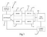
- FIG. 1is a block diagram of an inductive power supply.
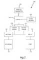
- FIG. 2is a block diagram of a secondary circuit.
- FIGS. 3A-3D togetherare a circuit diagram of an inductive power supply.
- FIG. 4is a circuit diagram of a secondary circuit.
- FIG. 5is a flowchart of a process to maintain resonance and adjust duty cycle.
- FIG. 6is a flowchart of a process to adjust the operating frequency to maintain resonance.
- FIG. 7is an exemplary graph showing frequency versus power transfer efficiency.
- FIG. 8is a timing diagram showing a varying duty cycle.
- FIG. 1An inductive power supply or primary circuit in accordance with an embodiment of the present invention is shown in FIG. 1 , and generally designated 100 .
- the primary circuit 100includes a primary controller 110 , a driver circuit 111 including a pair of drivers 112 , 114 , a switching circuit 115 including a pair of switches 116 , 118 , a tank circuit 120 a primary sensor 122 and an optional wireless receiver 124 .
- the primary controller 110 , driver circuit 111 and the switching circuit 115together generate an AC signal at a selected frequency and selected duty cycle that is applied to the tank circuit 120 to create an inductive field for transferring power wirelessly to a secondary circuit.
- a secondary circuit in accordance with an embodiment of the present inventionis shown in FIG. 2 , and generally designated 200 .
- the secondary circuit 200may include a secondary 210 , a rectifier 212 , a switch 214 , a load 216 , a current sensor 218 or voltage sensor 220 , a secondary controller 222 , a signal resistor 224 for communicating using reflected impedance and an optional wireless transmitter 226 .
- the initial operating frequencyis set substantially at resonant frequency 504 and the initial duty cycle is set at a relatively low value 506 .
- the primary controllercontinuously adjusts the operating frequency 508 to maintain substantially resonant frequency and continuously determines if the amount of power being transferred is too high 510 . If too much power is being provided or temperatures are above a preset threshold then the duty cycle is decreased 514 . If too little power is being provided then the duty cycle is increased 512 .
- Various conditionsmay temporarily or permanently reduce or halt the power transfer.
- the present inventionis suitable for use with a wide variety of inductive power supplies.
- inductive power supplyis intended to broadly include any inductive power supply capable of providing power wirelessly.
- the present inventionis also suitable for use with “adaptive inductive power supplies.”
- adaptive inductive power supplyis intended to broadly include any inductive power supply capable of providing power wirelessly at a plurality of different frequencies.
- the present inventionis described in connection with a particular adaptive inductive power supply, shown in FIGS. 3A-3D and generally designated 300 .
- the illustrated adaptive inductive power supply 300is merely exemplary, however, and the present invention may be implemented with essentially any inductive power supply that can be modified to provide inductive power at varying duty cycles.
- the adaptive inductive power supply 300generally includes a primary controller 310 , a low voltage power supply 312 , memory 314 , a driver circuit 316 , a switching circuit 318 a tank circuit 320 , a current sensor 322 , a filter 324 and optionally a wireless receiver 326 .
- the primary controller 310 , driver circuit 316 and switching circuit 318apply power to the tank circuit 320 to generate a source of electromagnetic inductive power at a selected frequency and a selected duty cycle.
- the primary controller 310 of the illustrated embodimentincludes two microcontrollers, one to control the frequency and one to control the duty cycle.
- the frequency microcontrollermay be a microcontroller, such as a PIC24FJ32GA002, or a more general purpose microprocessor.
- the duty cycle microcontrollermay be a microcontroller, such as a dsPIC30F2020, or a more general purpose microprocessor.
- the primary controller 310may be implemented using a single microcomputer, FPGA, analog or digital circuit.
- the driver circuit 316may be discrete components, as shown in FIG. 3D , or they may be incorporated into the primary controller 310 .
- An oscillator(not shown) may be included within the primary controller 310 .
- the primary circuit 300may also include a low voltage power supply 312 for supplying low voltage power to the primary controller 310 , the driver circuit as well as any other components requiring low voltage power for operation.
- the low voltage power supply 312provides scales the input voltage to 3.3 volts. In alternative embodiments, a different voltage may be provided.
- the various components of the primary circuit 310collectively drive the tank circuit 320 at a frequency and duty cycle dictated by the primary controller 310 . More specifically, the primary controller 310 controls the timing of the driver circuit 316 and switching circuit 318 .
- the timingrefers to both the frequency and duty cycle of the signal being generated. Frequency as it is being used here refers to the number of repetitions per unit time of a complete waveform.
- Duty cyclerefers to the proportion of time during which the waveform is high compared to the total amount of time for a complete waveform. Thus, a square wave as shown in FIG. 8 , may be described by its frequency and its duty cycle. Further, the duty cycle may be adjusted while maintaining the same frequency and the frequency may be adjusted while maintaining the same duty cycle.
- the driver circuit 316 of the illustrated embodimentincludes two separate drivers and may include additional circuit components to boost and filter the signal. For example, in the current embodiment, the signal is boosted to 20 volts, without effecting the timing of the signal.
- the switching circuit 318includes two switches.
- the switchesare implemented as MOS field effect transistors.
- other circuit componentsmay be used to implement the switching circuit.
- MOSFETs with different characteristicsmay be implemented during manufacture.
- multiple sets of switchesmay be provided on the circuit board, allowing one set of switches to be soldered at the time of manufacture based on the particular power requirements of that application.
- the switching circuit 115includes two separate switches 116 , 118 that are switched on at the same frequency, but out of phase with each other.
- FIG. 8illustrates the timing for one embodiment of such a switching circuit.
- both switcheshave the same duty cycle, but are shifted in time from each other by half of the period of the switching waveform.
- each switchmay have a different duty cycle and they the switches may be shifted in time a different amount from each other. That is, half period separation and similar duty cycle are desirable, but unnecessary, for the switches because it may result in increased power transfer efficiency from the inductive power supply to the remote device.
- the tank circuit 320generally includes the primary and a capacitor.
- the primary of the current embodimentis an air-core coil inductor.
- a cored inductorcan also be used if the proper considerations are made for spatial freedom, monitoring overall power, and feedback.
- the capacitance of the capacitormay be selected to balance the impedance of the primary coil at anticipated operating parameters.
- An inductive power supplymay be fabricated which at the time of soldering can have an appropriate capacitance value selected by soldering or switching different capacitors into the circuit.
- the tank circuit 320may be either a series resonant tank circuit (as shown in FIG.
- the present inventionmay be incorporated into the adaptive inductive power supply shown in U.S. Pat. No. 6,825,620, which is incorporated herein by reference.
- the present inventionmay be incorporated into the adaptive inductive power supply shown in U.S. Patent Application Publication US2004/130916A1 to Baarman, which is entitled “Adapted Inductive Power Supply” and was published on Jul. 8, 2004 (U.S. Ser. No. 10/689,499, filed on Oct. 20, 2003), which is also incorporated herein by reference.
- an adaptive inductive power supplycapable of establishing wireless communications with the remote device
- an adaptive inductive power supplycapable of establishing wireless communications with the remote device
- an adaptive inductive power supplyshown in U.S. Patent Application Publication US 2004/130915A1 to Baarman, which is entitled “Adapted Inductive Power Supply with Communication” and was published on Jul. 8, 2004 (U.S. Ser. No. 10/689,148, filed on Oct. 20, 2003), which is incorporated herein by reference.
- a printed circuit board coilsuch as a printed circuit board coil incorporating the invention principles of U.S. Ser. No. 60/975,953, which is entitled “Printed Circuit Board Coil” and filed on Sep.
- the inductormay be implemented as a multi-tap inductor and/or the capacitors may be implemented as a switched capacitor bank that may be used to dynamically, before or during use, alter the resonance of the primary circuit, for example, as described in U.S. Pat. No. 7,212,414, which is entitled “Adaptive Inductive Power Supply” and issued May 1, 2007, to Baarman, which is herein incorporated by reference.
- the primary controller 310may establish the operating frequency as a function of input from the current sensor 322 .
- the controller 310operates the driver circuit 318 at the frequency established by the primary controller 310 .
- the driver circuit 316provides the signals necessary to operate the switching circuit 318 .
- the switching circuit 318provides AC (alternating current) power to the tank circuit 320 from a source of DC (direct current) power.
- the operating frequencyis established from a separate communication link, such as the wireless receiver 326 , implemented in the current embodiment as an IR receiver.
- the primary controller 310may also establish the duty cycle as a function of input from the current sensor 322 . Planned shunting of the signal resistor on the secondary, which will be described in more detail below, may be used to provide information to the primary using reflected impedance detected with the current sensor 322 .
- the duty cyclemay be established using a separate communication link, such as the wireless receiver 326 , implemented in the current embodiment as an IR receiver. This could also be near field or other RF communication channels.
- the current sensor 322is a current transformer having a primary coil connected to the tank circuit and a secondary coil connected to the primary controller 310 .
- the current sensor 322includes circuitry to adjust the gain of the output of the current sensor to accommodate the ranges accepted by the primary controller 310 . Further, the amount of gain may be adjusted by the primary controller 310 by applying a signal to the switch.
- the inductive power supply 300may include conditioning circuitry 324 for conditioning the current transformer output before it is supplied to the primary controller 310 .
- the conditioning circuitry 324is a 5K Hz 2-pole filter.
- the inductive power supply 300may include essentially any alternative type of sensor capable of providing information regarding reflected impedance from the secondary 400 .
- the current sensor 322 of the illustrated embodimentis connected directly to the tank circuit, the current sensor (or other reflected impedance sensor) can be located in essentially any location where it is capable of providing readings indicative of the reflected impedance.
- the inductive power supply 300further includes a memory 314 capable of storing information relating to the operating parameters of a plurality of secondaries 400 .
- the stored informationmay be used to permit the inductive power supply 300 to more efficiently power the secondary 400 and more readily recognize fault conditions.
- the inductive power supply 300may be intended for use with a specific set of secondaries 400 .
- the memory 314includes the unique resonant frequency (or pattern of frequencies) for each secondary 400 , along with the desired collection of associated information, such as maximum and minimum operating frequencies, current usage and minimum and maximum duty cycle.
- the memory 314may, however, include essentially any information that may be useful to the inductive power supply 300 in operating the secondary 400 .
- the memory 314may include information regarding the wireless communication protocol of the remote device 400 .
- the present inventionis intended for use with a wide variety of remote devices or secondaries of varying designs and constructions. It is anticipated that these various remote devices will require power at varying frequency and will have different power requirements.
- the secondary circuit 400generally includes a secondary 410 for receiving power from the inductive power supply 300 , a rectifier 414 (or other components for converting AC power to DC), a low voltage power supply 412 that scales the received power to operate the secondary controller 428 , conditioning circuitry 416 , 426 to remove ripple in the signal, current sensor 418 , voltage sensor 422 , switch 420 , load 424 , secondary controller 428 , a signal resistor 432 and an optional wireless transmitter 430 .
- the rectifier 414converts the AC power generated in the secondary 410 to DC power, which is typically needed to power the load.
- the loadis a charging circuit (not shown) for a battery.
- Charging circuitsare well-known and are widely used with a variety of rechargeable electronic devices. If desired, the charging circuit may be configured to both charge a battery (not shown) and/or power the load 424 . In alternative embodiments the rectifier may be unnecessary and AC power may be conditioned to be used to power the load.
- the current sensor 418detects the amount of current in the received power and provides that information to the secondary controller 428 .
- the voltage sensor 422detects the amount of voltage in the received power and provides that information to the secondary controller 428 .
- the illustrated embodimentincludes both a voltage sensor 422 and a current sensor 418 , only one is necessary.
- the primary controllercan calculate the power transfer efficiency. By sweeping a range of operating frequencies, noting the power transfer efficiency at each frequency, the operating frequency closest to resonance can be determined—it corresponds with the operating frequency that yields the best power transfer efficiency.
- the voltage and current sensors 418 , 422can be used in conjunction with a protection algorithm in the secondary controller 428 to disconnect the load 424 if a fault condition is detected.
- This conceptis described in more detail in U.S. patent application Ser. No. 11/855,710 entitled System and Method for Inductively Charging a Battery to Baarman et al, which was previously incorporated by reference.
- the secondary controller 428may be essentially any type of microcontroller.
- the secondary controller 428is an ATTINY24V-10MU microcontroller.
- the secondary controller 428generally includes an analog to digital converter, and is programmed to process the voltage and/or current readings and transmit them to the primary controller 310 of the inductive power supply 300 .
- the microprocessormay also include other code unrelated to the frequency or duty cycle control processes.
- Communication of the sensed voltage and/or current in the secondarymay be transmitted to the primary controller 310 in a variety of ways.
- the informationmay be transmitted using the signal resistor 432 or the wireless transmitter 430 .
- signal resistor 432may be used to send information to the primary controller 310 .
- the use of a signal resistor 432 to provide communication from the secondary to the primarywas discussed in U.S. patent application Ser. No. 11/855,710 entitled System and Method for Inductively Charging a Battery to Baarman et al, which is herein incorporated by reference.
- the signal resistor 432when shunted, sends a communication signal that signifies an over-current or over-voltage state. When the resistor is shunted, the peak detector on the primary circuit is able to sense the over-voltage/over-current condition and act accordingly.
- the signal resistor 432 of the present inventionmay be shunted systematically to communicate additional data to the primary controller 310 . For example, a stream of data could represent the sensed current and/or sensed voltage. Alternatively, the signal resistor could be used solely in the previously described way as an over-voltage/over-current transmitter or it could be removed entirely.
- the primary circuitdetermines and sets the initial operating frequency 504 .
- the goal of setting the initial operating frequencyis to set it as close to the resonant frequency as possible, which varies depending on many different factors including, among other things, the orientation and distance between the primary circuit and secondary circuit.
- a simple frequency sweepis used to determine where to set the initial operation frequency.
- the range of valid frequenciesis swept and the power transfer efficiency at each frequency is noted.
- the step between frequenciesmay vary, but in the current embodiment, the frequency is swept between 70 k Hz and 250 k Hz at steps of 100 Hz. Once the entire range of frequencies has been swept, the operating frequency that yielded the highest power transfer efficiency is selected as the initial operating frequency.
- the operating frequency that yielded the highest power transfer efficiencyindicates that it is the closest frequency to resonance. Further steps at a finer frequency resolution can facilitate even further tuning.
- Other methods for determining the initial operating frequencymay be used in alternative embodiments. For example, an initial operating frequency may be selected based on known primary and secondary component. Further, modifications to the sweeping process may include dynamic step adjustment proportional to the power transfer efficiency. In yet another alternative embodiment, the sweep may be performed dynamically so that only the power transfer efficiency value for the current frequency and the frequency with the highest power transfer efficiency are stored. As the sweep progresses, each value is checked against the highest stored value and replaces it only if it is higher.
- the primary circuitsets the initial duty cycle 506 .
- the duty cyclecorresponds with the amount of power transferred with each cycle. The higher the duty cycle, the more power transferred per cycle.
- the initial duty cycleis set at 20%, which is considered low enough to not risk over-powering the remote device, but is high enough such that enough power is transferred to power the secondary circuitry.
- a different initial duty cyclemay be set based on the application or any number of other factors.
- the adjust operating frequency step 508is a multi-step process which ensures that the operating frequency is being maintained substantially at resonance.
- FIG. 6describes one embodiment of this process in more detail.
- the operating frequencyis increased by a pre-selected amount, referred to as a step up.
- the adjustmentis allowed to propagate through the system and the power efficiency is checked 604 . If the power efficiency increased then the system was not substantially at resonance and the operating frequency is stepped up again. This process continues until the power efficiency either decreases or stays the same. Once that occurs, the operating frequency is stepped down 606 .
- the power efficiencyis checked 608 . If the power efficiency increases then the operating frequency is stepped down again, until the power efficiency stays the same or decreases.
- the final stepis to step up the operating frequency 610 to get back to the operating frequency with the peak power efficiency. This is merely one embodiment of a process to maintain the operating frequency substantially at resonance. Any other process could be used to maintain the operating frequency substantially at resonance.
- FIG. 7An exemplary graph of operating frequency vs. power efficiency, shown in FIG. 7 .
- the initial sweep of frequenciessets the operating frequency to the resonant frequency, i.e. the highest peak on FIG. 7 .
- the power efficiency valuesmay have changed as a result in any number of factors, most notably movement of the secondary.
- the change in the graphis merely a slight shift, meaning that the optimum operating frequency may be a few steps in either direction. This is why the current embodiment steps up and steps down.
- the processimmediately steps down until. If stepping down also leads to a decrease in power efficiency transfer then it is evident that no adjustment is necessary and the operating frequency was already at resonant frequency.
- an analog circuitcould be used to directly determine how far off resonance the system is, causing the controller to react directly to the proper frequency.
- a phase comparatoris one such circuit.
- the operating frequencyis adjusted with each iteration, however, in alternative embodiments, the operating frequency may be adjusted less frequently or only when an event triggers that it should be adjusted. For example, if a motion detector on the secondary indicates movement or a change in orientation of the secondary. Or, for example, if there is a sharp decrease or increase in the amount of power provided to the secondary.
- the next stepis to determine if the amount of power being received by the secondary is too high 510 . If the amount of power being received is too high then the duty cycle of the power being transferred is reduced 514 . If the amount of power being received is not too high then the duty cycle of the power being transferred is increased 512 . In the current embodiment, the duty cycle should not exceed approximately 49% in order to reduce the risk of causing a short circuit. In the current embodiment, after the duty cycle is adjusted, up or down, the operating frequency is re-adjusted 508 . As explained above, duty cycle refers to the “switch on time” or the proportion of time during which the waveform is high compared to the total amount of time for a complete waveform.
- FIG. 8An exemplary graph illustrating a signal with a varying duty cycle is shown in FIG. 8 .
- the graphdepicts a graph of time vs. current.
- the solid linerepresents the waveform generated by the primary circuit with the current duty cycle.
- the dashed linerepresents what a waveform would look like with an increased duty cycle.
- the dash-dotted linerepresents what a waveform would look like with a decreased duty cycle. Note that because the duty cycle is being increased symmetrically and decreased symmetrically, the frequency of the waveform does not change with the adjustment in duty cycle. It is worth noting that in some embodiments, during operation, the frequency may not be adjusted, while duty cycle adjustments continue to take place.
- Duty cyclemay be stepped up or down by a pre-selected amount.
- the step up and step down amountsare static and equal.
- the step amountsmay be dynamic and different.
- the duty cyclemay be stepped up or down proportional to the amount of power demanded by the secondary. The amount of power demanded by the secondary can be determined by reading the current and/or voltage sensor. Where there is a small change in the readings, a small change in duty cycle may be implemented and where there is a large change in the readings, a large change in duty cycle may be implemented.
- delaysbetween the changes in operating frequency and changes in duty cycle. These delays can account for any phase issues that may arise because of the speed at which the operating frequency or duty cycle is being changed.
- the primary circuitmay adjust the duty cycle depending on the demands of the secondary. For example, in one embodiment, one goal may be to maintain a certain amount of voltage or current in the secondary. Using feedback from the secondary, such as the sensed voltage and/or current, the operating frequency may be adjusted to ensure optimum power transfer efficiency by ensuring operation at substantially resonant frequency and the duty cycle may be adjusted to provide additional or less power to meet the desired goal.
Landscapes
- Engineering & Computer Science (AREA)
- Power Engineering (AREA)
- Computer Networks & Wireless Communication (AREA)
- Signal Processing (AREA)
- Charge And Discharge Circuits For Batteries Or The Like (AREA)
- Dc-Dc Converters (AREA)
- Near-Field Transmission Systems (AREA)
Abstract
Description
The present invention relates to inductive power and more particularly to a system and method for wirelessly supplying power.
In recent years, wireless power supply systems have received increased attention because of some of their benefits over traditional wired power supply systems. Some more basic wireless power supply systems are specifically designed to charge a particular device, which can help minimize power transfer efficiency issues. Other wireless power supply systems attempt to account for misalignment, charge different remote devices and provide different amounts of power. In these systems, maintaining an acceptable power transfer efficiency can be difficult.
Some wireless power systems adjust the operating frequency of an AC signal across the tank circuit closer to or further from resonance to increase or decrease the amount of power delivered to the remote device. Other wireless power systems adjust the resonant frequency of the tank circuit closer to or further from the operating frequency. One issue with these systems is that the power transfer efficiency between the inductive power supply and the remote device is a function of how close the operating frequency is to resonance. So, while adjusting the operating frequency or resonant frequency can provide some control over the amount of power delivered to the remote device, it may come at the cost of decreased power transfer efficiency.
Other wireless power supplies use a fixed operating frequency and instead adjust the rail voltage, duty cycle, or phase of the AC signal across the tank circuit to increase or decrease the amount of power delivered to the remote device. One issue with this is that in order for the power transfer efficiency to be acceptable, the inductive power supply and remote device may need to be precisely aligned and specifically designed to work with each other.
The present invention provides an inductive power supply that maintains resonance and adjusts duty cycle based on feedback from a secondary circuit. In one embodiment, the inductive power supply includes a primary controller, a driver circuit, a switching circuit, and a tank circuit. The controller, driver circuit and switching circuit cooperate to generate an AC signal at a selected operating frequency and duty cycle. The AC signal is applied to the tank circuit to create an inductive field for powering the secondary. The secondary communicates feedback about the received power back to the primary controller. The power transfer efficiency may be optimized by maintaining the operating frequency substantially at resonance, and the amount of power transferred may be controlled by adjusting the duty cycle.
In one embodiment, the secondary circuit includes a secondary, a rectifier, a switch, a load, a sensor, a secondary controller, and a communication means. A voltage and/or current sensor detects characteristics about the power which are transmitted back to the primary controller using the communication means. Optionally, over-voltage and over-current protection may be provided. If a fault condition is detected the load is disconnected using the switch.
In one embodiment, a process for inductively powering a load by maintaining substantial resonance and adjusting duty cycle is provided. Initially an operating frequency and duty cycle are set to an acceptable value. The initial operating frequency is determined by sweeping a range of frequencies and selecting the operating frequency which provided the highest power transfer efficiency. The initial duty cycle is set to a relatively low value, such as 20%, to ensure that too much power is not delivered to the secondary. Once the initial values have been set, the inductive power supply enters a continuous process of adjusting the operating frequency to maintain substantial resonance and adjusting the duty cycle depending on whether the amount of power is too high or too low or temperature is too high.
The present invention provides a simple and effective system and method for providing a selected amount of wireless power while maintaining a high transfer efficiency. Adjustment of duty cycle provides another level of control of wireless power transfer, one which can be used to fine tune the amount of power provided to a secondary. Additionally, the ability to adjust the amount of power being transferred while maintaining substantial resonance results in fewer overall losses and easier fulfillment of specified power requirements.
These and other objects, advantages, and features of the invention will be readily understood and appreciated by reference to the detailed description of the current embodiment and the drawings.
An inductive power supply or primary circuit in accordance with an embodiment of the present invention is shown inFIG. 1 , and generally designated100. Theprimary circuit 100 includes aprimary controller 110, adriver circuit 111 including a pair ofdrivers switching circuit 115 including a pair ofswitches primary sensor 122 and an optionalwireless receiver 124. Theprimary controller 110,driver circuit 111 and theswitching circuit 115 together generate an AC signal at a selected frequency and selected duty cycle that is applied to thetank circuit 120 to create an inductive field for transferring power wirelessly to a secondary circuit. A secondary circuit in accordance with an embodiment of the present invention is shown inFIG. 2 , and generally designated200. Thesecondary circuit 200 may include a secondary210, arectifier 212, aswitch 214, aload 216, acurrent sensor 218 orvoltage sensor 220, asecondary controller 222, asignal resistor 224 for communicating using reflected impedance and an optionalwireless transmitter 226.
In operation, an embodiment of the process for adjusting the duty cycle is shown inFIG. 5 , the initial operating frequency is set substantially atresonant frequency 504 and the initial duty cycle is set at a relativelylow value 506. The primary controller continuously adjusts theoperating frequency 508 to maintain substantially resonant frequency and continuously determines if the amount of power being transferred is too high510. If too much power is being provided or temperatures are above a preset threshold then the duty cycle is decreased514. If too little power is being provided then the duty cycle is increased512. Various conditions may temporarily or permanently reduce or halt the power transfer.
The present invention is suitable for use with a wide variety of inductive power supplies. As used herein, the term “inductive power supply” is intended to broadly include any inductive power supply capable of providing power wirelessly. The present invention is also suitable for use with “adaptive inductive power supplies.” As used herein, the term “adaptive inductive power supply” is intended to broadly include any inductive power supply capable of providing power wirelessly at a plurality of different frequencies. For purposes of disclosure, the present invention is described in connection with a particular adaptive inductive power supply, shown inFIGS. 3A-3D and generally designated300. The illustrated adaptive inductive power supply300 is merely exemplary, however, and the present invention may be implemented with essentially any inductive power supply that can be modified to provide inductive power at varying duty cycles.
In the illustrated embodiment, the adaptive inductive power supply300 generally includes aprimary controller 310, a low voltage power supply312,memory 314, adriver circuit 316, a switching circuit318 atank circuit 320, acurrent sensor 322, afilter 324 and optionally awireless receiver 326. In operation, theprimary controller 310,driver circuit 316 andswitching circuit 318 apply power to thetank circuit 320 to generate a source of electromagnetic inductive power at a selected frequency and a selected duty cycle.
Theprimary controller 310 of the illustrated embodiment includes two microcontrollers, one to control the frequency and one to control the duty cycle. The frequency microcontroller may be a microcontroller, such as a PIC24FJ32GA002, or a more general purpose microprocessor. The duty cycle microcontroller may be a microcontroller, such as a dsPIC30F2020, or a more general purpose microprocessor. In alternative embodiments, theprimary controller 310 may be implemented using a single microcomputer, FPGA, analog or digital circuit. Thedriver circuit 316 may be discrete components, as shown inFIG. 3D , or they may be incorporated into theprimary controller 310. An oscillator (not shown) may be included within theprimary controller 310.
The primary circuit300 may also include a low voltage power supply312 for supplying low voltage power to theprimary controller 310, the driver circuit as well as any other components requiring low voltage power for operation. In the illustrated embodiment the low voltage power supply312 provides scales the input voltage to 3.3 volts. In alternative embodiments, a different voltage may be provided.
In the current embodiment, the various components of theprimary circuit 310 collectively drive thetank circuit 320 at a frequency and duty cycle dictated by theprimary controller 310. More specifically, theprimary controller 310 controls the timing of thedriver circuit 316 and switchingcircuit 318. The timing refers to both the frequency and duty cycle of the signal being generated. Frequency as it is being used here refers to the number of repetitions per unit time of a complete waveform. Duty cycle refers to the proportion of time during which the waveform is high compared to the total amount of time for a complete waveform. Thus, a square wave as shown inFIG. 8 , may be described by its frequency and its duty cycle. Further, the duty cycle may be adjusted while maintaining the same frequency and the frequency may be adjusted while maintaining the same duty cycle. Thedriver circuit 316 of the illustrated embodiment includes two separate drivers and may include additional circuit components to boost and filter the signal. For example, in the current embodiment, the signal is boosted to 20 volts, without effecting the timing of the signal.
Theswitching circuit 318 includes two switches. In the current embodiment, the switches are implemented as MOS field effect transistors. In alternative embodiments, other circuit components may be used to implement the switching circuit. Additionally, depending on power requirements MOSFETs with different characteristics may be implemented during manufacture. In some embodiments, multiple sets of switches may be provided on the circuit board, allowing one set of switches to be soldered at the time of manufacture based on the particular power requirements of that application.
In one embodiment, theswitching circuit 115 includes twoseparate switches FIG. 8 illustrates the timing for one embodiment of such a switching circuit. InFIG. 8 , both switches have the same duty cycle, but are shifted in time from each other by half of the period of the switching waveform. In alternative embodiments, each switch may have a different duty cycle and they the switches may be shifted in time a different amount from each other. That is, half period separation and similar duty cycle are desirable, but unnecessary, for the switches because it may result in increased power transfer efficiency from the inductive power supply to the remote device.
Thetank circuit 320 generally includes the primary and a capacitor. The primary of the current embodiment is an air-core coil inductor. A cored inductor can also be used if the proper considerations are made for spatial freedom, monitoring overall power, and feedback. The capacitance of the capacitor may be selected to balance the impedance of the primary coil at anticipated operating parameters. In the current embodiment, although three tank capacitors are shown, all three capacitors need not necessarily be soldered into the circuit at the time of manufacture. An inductive power supply may be fabricated which at the time of soldering can have an appropriate capacitance value selected by soldering or switching different capacitors into the circuit. Thetank circuit 320 may be either a series resonant tank circuit (as shown inFIG. 3D ) or a parallel resonant tank circuit (not shown). The present invention may be incorporated into the adaptive inductive power supply shown in U.S. Pat. No. 6,825,620, which is incorporated herein by reference. As another example, the present invention may be incorporated into the adaptive inductive power supply shown in U.S. Patent Application Publication US2004/130916A1 to Baarman, which is entitled “Adapted Inductive Power Supply” and was published on Jul. 8, 2004 (U.S. Ser. No. 10/689,499, filed on Oct. 20, 2003), which is also incorporated herein by reference. Further, it may be desirable to use the present invention in connection with an adaptive inductive power supply capable of establishing wireless communications with the remote device, such as the adaptive inductive power supply shown in U.S. Patent Application Publication US 2004/130915A1 to Baarman, which is entitled “Adapted Inductive Power Supply with Communication” and was published on Jul. 8, 2004 (U.S. Ser. No. 10/689,148, filed on Oct. 20, 2003), which is incorporated herein by reference. Further yet, it may be desirable to use the present invention with a printed circuit board coil, such as a printed circuit board coil incorporating the invention principles of U.S. Ser. No. 60/975,953, which is entitled “Printed Circuit Board Coil” and filed on Sep. 28, 2007 by Baarman et al, and which is incorporated herein by reference in its entirety. In other alternative embodiments, the inductor may be implemented as a multi-tap inductor and/or the capacitors may be implemented as a switched capacitor bank that may be used to dynamically, before or during use, alter the resonance of the primary circuit, for example, as described in U.S. Pat. No. 7,212,414, which is entitled “Adaptive Inductive Power Supply” and issued May 1, 2007, to Baarman, which is herein incorporated by reference.
In certain modes of operation, theprimary controller 310 may establish the operating frequency as a function of input from thecurrent sensor 322. Thecontroller 310, in turn, operates thedriver circuit 318 at the frequency established by theprimary controller 310. Thedriver circuit 316 provides the signals necessary to operate theswitching circuit 318. As a result, theswitching circuit 318 provides AC (alternating current) power to thetank circuit 320 from a source of DC (direct current) power. In an alternative embodiment, the operating frequency is established from a separate communication link, such as thewireless receiver 326, implemented in the current embodiment as an IR receiver.
Theprimary controller 310 may also establish the duty cycle as a function of input from thecurrent sensor 322. Planned shunting of the signal resistor on the secondary, which will be described in more detail below, may be used to provide information to the primary using reflected impedance detected with thecurrent sensor 322. Alternatively, the duty cycle may be established using a separate communication link, such as thewireless receiver 326, implemented in the current embodiment as an IR receiver. This could also be near field or other RF communication channels.
In the illustrated embodiment, thecurrent sensor 322 is a current transformer having a primary coil connected to the tank circuit and a secondary coil connected to theprimary controller 310. In the current embodiment, thecurrent sensor 322 includes circuitry to adjust the gain of the output of the current sensor to accommodate the ranges accepted by theprimary controller 310. Further, the amount of gain may be adjusted by theprimary controller 310 by applying a signal to the switch. The inductive power supply300 may includeconditioning circuitry 324 for conditioning the current transformer output before it is supplied to theprimary controller 310. In the current embodiment, theconditioning circuitry 324 is a 5K Hz 2-pole filter. Although the illustrated embodiment includes a current transformer for sensing the reflected impedance of the secondary or remote device, the inductive power supply300 may include essentially any alternative type of sensor capable of providing information regarding reflected impedance from the secondary400. Further, although thecurrent sensor 322 of the illustrated embodiment is connected directly to the tank circuit, the current sensor (or other reflected impedance sensor) can be located in essentially any location where it is capable of providing readings indicative of the reflected impedance.
In the illustrated embodiment, the inductive power supply300 further includes amemory 314 capable of storing information relating to the operating parameters of a plurality ofsecondaries 400. The stored information may be used to permit the inductive power supply300 to more efficiently power the secondary400 and more readily recognize fault conditions. In some applications, the inductive power supply300 may be intended for use with a specific set ofsecondaries 400. In these applications, thememory 314 includes the unique resonant frequency (or pattern of frequencies) for each secondary400, along with the desired collection of associated information, such as maximum and minimum operating frequencies, current usage and minimum and maximum duty cycle. Thememory 314 may, however, include essentially any information that may be useful to the inductive power supply300 in operating the secondary400. For example, in applications where it is desirable to establish wireless communications with the secondary400, thememory 314 may include information regarding the wireless communication protocol of theremote device 400.
The present invention is intended for use with a wide variety of remote devices or secondaries of varying designs and constructions. It is anticipated that these various remote devices will require power at varying frequency and will have different power requirements.
For purposes of disclosure, one embodiment of asecondary circuit 400 is shown inFIG. 4 . In the embodiment ofFIG. 4 , thesecondary circuit 400 generally includes a secondary410 for receiving power from the inductive power supply300, a rectifier414 (or other components for converting AC power to DC), a lowvoltage power supply 412 that scales the received power to operate thesecondary controller 428,conditioning circuitry current sensor 418,voltage sensor 422,switch 420,load 424,secondary controller 428, asignal resistor 432 and anoptional wireless transmitter 430. In operation, therectifier 414 converts the AC power generated in the secondary410 to DC power, which is typically needed to power the load. Alternatively, multiple secondary coils receiving power on different phases can be used to reduce the ripple voltage. This is referenced inApplication 60/976,137, entitled Multiphase Inductive Power Supply System to Baarman et al, which is herein incorporated by reference. Multiple primary coils may be desired to transmit power on different phases in such an embodiment. In one embodiment, the load is a charging circuit (not shown) for a battery. Charging circuits are well-known and are widely used with a variety of rechargeable electronic devices. If desired, the charging circuit may be configured to both charge a battery (not shown) and/or power theload 424. In alternative embodiments the rectifier may be unnecessary and AC power may be conditioned to be used to power the load.
Thecurrent sensor 418 detects the amount of current in the received power and provides that information to thesecondary controller 428. Thevoltage sensor 422 detects the amount of voltage in the received power and provides that information to thesecondary controller 428. Although the illustrated embodiment includes both avoltage sensor 422 and acurrent sensor 418, only one is necessary. By sensing the voltage and/or current in the secondary circuit and knowing the voltage and/or current provided by the primary circuit, the primary controller can calculate the power transfer efficiency. By sweeping a range of operating frequencies, noting the power transfer efficiency at each frequency, the operating frequency closest to resonance can be determined—it corresponds with the operating frequency that yields the best power transfer efficiency. In addition, the voltage andcurrent sensors secondary controller 428 to disconnect theload 424 if a fault condition is detected. This concept is described in more detail in U.S. patent application Ser. No. 11/855,710 entitled System and Method for Inductively Charging a Battery to Baarman et al, which was previously incorporated by reference.
Thesecondary controller 428 may be essentially any type of microcontroller. In the illustrated embodiment, thesecondary controller 428 is an ATTINY24V-10MU microcontroller. Thesecondary controller 428 generally includes an analog to digital converter, and is programmed to process the voltage and/or current readings and transmit them to theprimary controller 310 of the inductive power supply300. The microprocessor may also include other code unrelated to the frequency or duty cycle control processes.
Communication of the sensed voltage and/or current in the secondary may be transmitted to theprimary controller 310 in a variety of ways. In the illustrated embodiment, the information may be transmitted using thesignal resistor 432 or thewireless transmitter 430.
In one embodiment,signal resistor 432 may be used to send information to theprimary controller 310. The use of asignal resistor 432 to provide communication from the secondary to the primary was discussed in U.S. patent application Ser. No. 11/855,710 entitled System and Method for Inductively Charging a Battery to Baarman et al, which is herein incorporated by reference. Thesignal resistor 432, when shunted, sends a communication signal that signifies an over-current or over-voltage state. When the resistor is shunted, the peak detector on the primary circuit is able to sense the over-voltage/over-current condition and act accordingly. Thesignal resistor 432 of the present invention may be shunted systematically to communicate additional data to theprimary controller 310. For example, a stream of data could represent the sensed current and/or sensed voltage. Alternatively, the signal resistor could be used solely in the previously described way as an over-voltage/over-current transmitter or it could be removed entirely.
Use of a wireless transmitter or transceiver was previously described in U.S. Patent Application Publication US 2004/130915A1 to Baarman, which is entitled “Adapted Inductive Power Supply with Communication” that was previously incorporated by reference. Specifically, the use of WIFI, infrared, blue tooth, cellular or RFID were previously discussed as ways to wirelessly transmit data from a remote device to an inductive power supply. Further, communication using the induction coils and a power line communication protocol was discussed. Any of these methods of transmitting data could be implemented in the present invention in order to transfer the desired data from the secondary to the primary.
General operation of theprimary circuit 100 andsecondary circuit 200 is described in connection withFIG. 5 .
In this embodiment, the primary circuit determines and sets theinitial operating frequency 504. Typically, the goal of setting the initial operating frequency is to set it as close to the resonant frequency as possible, which varies depending on many different factors including, among other things, the orientation and distance between the primary circuit and secondary circuit. In the current embodiment, a simple frequency sweep is used to determine where to set the initial operation frequency. Specifically, in this embodiment, the range of valid frequencies is swept and the power transfer efficiency at each frequency is noted. The step between frequencies may vary, but in the current embodiment, the frequency is swept between 70 k Hz and 250 k Hz at steps of 100 Hz. Once the entire range of frequencies has been swept, the operating frequency that yielded the highest power transfer efficiency is selected as the initial operating frequency. The operating frequency that yielded the highest power transfer efficiency indicates that it is the closest frequency to resonance. Further steps at a finer frequency resolution can facilitate even further tuning. Other methods for determining the initial operating frequency may be used in alternative embodiments. For example, an initial operating frequency may be selected based on known primary and secondary component. Further, modifications to the sweeping process may include dynamic step adjustment proportional to the power transfer efficiency. In yet another alternative embodiment, the sweep may be performed dynamically so that only the power transfer efficiency value for the current frequency and the frequency with the highest power transfer efficiency are stored. As the sweep progresses, each value is checked against the highest stored value and replaces it only if it is higher.
In the embodiment described inFIG. 5 , the primary circuit sets theinitial duty cycle 506. The duty cycle corresponds with the amount of power transferred with each cycle. The higher the duty cycle, the more power transferred per cycle. In the current embodiment, the initial duty cycle is set at 20%, which is considered low enough to not risk over-powering the remote device, but is high enough such that enough power is transferred to power the secondary circuitry. In alternative embodiments a different initial duty cycle may be set based on the application or any number of other factors.
The adjustoperating frequency step 508 is a multi-step process which ensures that the operating frequency is being maintained substantially at resonance.FIG. 6 describes one embodiment of this process in more detail. In the described embodiment, the operating frequency is increased by a pre-selected amount, referred to as a step up. The adjustment is allowed to propagate through the system and the power efficiency is checked604. If the power efficiency increased then the system was not substantially at resonance and the operating frequency is stepped up again. This process continues until the power efficiency either decreases or stays the same. Once that occurs, the operating frequency is stepped down606. The power efficiency is checked608. If the power efficiency increases then the operating frequency is stepped down again, until the power efficiency stays the same or decreases. The final step is to step up theoperating frequency 610 to get back to the operating frequency with the peak power efficiency. This is merely one embodiment of a process to maintain the operating frequency substantially at resonance. Any other process could be used to maintain the operating frequency substantially at resonance.
One reason that the operating frequency is stepped up and stepped down can be explained by looking at an exemplary graph of operating frequency vs. power efficiency, shown inFIG. 7 . As can be seen, there are several peaks of power efficiency over the range of operating frequencies shown. The initial sweep of frequencies sets the operating frequency to the resonant frequency, i.e. the highest peak onFIG. 7 . Each time the adjustment comes, although the operating frequency has not changed, the power efficiency values may have changed as a result in any number of factors, most notably movement of the secondary. Typically, the change in the graph is merely a slight shift, meaning that the optimum operating frequency may be a few steps in either direction. This is why the current embodiment steps up and steps down. If the first step up leads to a decrease in power efficiency transfer, the process immediately steps down until. If stepping down also leads to a decrease in power efficiency transfer then it is evident that no adjustment is necessary and the operating frequency was already at resonant frequency. In an alternative embodiment an analog circuit could be used to directly determine how far off resonance the system is, causing the controller to react directly to the proper frequency. A phase comparator is one such circuit.
In the current embodiment, the operating frequency is adjusted with each iteration, however, in alternative embodiments, the operating frequency may be adjusted less frequently or only when an event triggers that it should be adjusted. For example, if a motion detector on the secondary indicates movement or a change in orientation of the secondary. Or, for example, if there is a sharp decrease or increase in the amount of power provided to the secondary.
The next step is to determine if the amount of power being received by the secondary is too high510. If the amount of power being received is too high then the duty cycle of the power being transferred is reduced514. If the amount of power being received is not too high then the duty cycle of the power being transferred is increased512. In the current embodiment, the duty cycle should not exceed approximately 49% in order to reduce the risk of causing a short circuit. In the current embodiment, after the duty cycle is adjusted, up or down, the operating frequency is re-adjusted508. As explained above, duty cycle refers to the “switch on time” or the proportion of time during which the waveform is high compared to the total amount of time for a complete waveform. An exemplary graph illustrating a signal with a varying duty cycle is shown inFIG. 8 . The graph depicts a graph of time vs. current. The solid line represents the waveform generated by the primary circuit with the current duty cycle. The dashed line represents what a waveform would look like with an increased duty cycle. The dash-dotted line represents what a waveform would look like with a decreased duty cycle. Note that because the duty cycle is being increased symmetrically and decreased symmetrically, the frequency of the waveform does not change with the adjustment in duty cycle. It is worth noting that in some embodiments, during operation, the frequency may not be adjusted, while duty cycle adjustments continue to take place.
Duty cycle may be stepped up or down by a pre-selected amount. In the current embodiment, the step up and step down amounts are static and equal. However, in alternative embodiments, the step amounts may be dynamic and different. For example, in battery charging applications it may be beneficial to decrease duty cycle in large steps and increase duty cycle in small steps. Various batteries require different charging algorithms and the duty cycle control may be used to provide the correct battery charging profile. In another example, the duty cycle may be stepped up or down proportional to the amount of power demanded by the secondary. The amount of power demanded by the secondary can be determined by reading the current and/or voltage sensor. Where there is a small change in the readings, a small change in duty cycle may be implemented and where there is a large change in the readings, a large change in duty cycle may be implemented.
In one embodiment, there are built-in delays between the changes in operating frequency and changes in duty cycle. These delays can account for any phase issues that may arise because of the speed at which the operating frequency or duty cycle is being changed.
This process continues as desired or until the power supply is turned off, the secondary is removed, or in the case of charging a battery, when the battery is fully charged.
The primary circuit may adjust the duty cycle depending on the demands of the secondary. For example, in one embodiment, one goal may be to maintain a certain amount of voltage or current in the secondary. Using feedback from the secondary, such as the sensed voltage and/or current, the operating frequency may be adjusted to ensure optimum power transfer efficiency by ensuring operation at substantially resonant frequency and the duty cycle may be adjusted to provide additional or less power to meet the desired goal.
The above description is that of the current embodiment of the invention. Various alterations and changes can be made without departing from the spirit and broader aspects of the invention.
Claims (34)
1. An inductive power supply for providing power wirelessly to a remote device, said inductive power supply comprising:
a primary circuit for controlling power transfer to the remote device according to at least one operating parameter, said primary circuit configured to adjust a duty cycle of a signal to allow variation in an amount of power transferred to the remote device;
a wireless receiver configured to receive information communicated from the remote device;
a tank circuit in electrical communication with said primary circuit, said tank circuit configured to inductively couple with the remote device;
wherein said primary circuit controls said at least one operating parameter to transfer power substantially near resonance;
wherein said primary circuit controls said duty cycle of said signal to control said amount of power transferred while controlling said at least one operating parameter to transfer power substantially near resonance; and
wherein, based on said information communicated from the remote device, said primary circuit adjusts at least one of said duty cycle to control said amount of power transferred and said at least one operating parameter to transfer power substantially near resonance.
2. The inductive power supply ofclaim 1 wherein said at least one operating parameter includes at least one of an operating frequency and a resonant frequency, and wherein said primary circuit is configured to maintain substantial resonance by controlling said at least one operating parameter.
3. The inductive power supply ofclaim 1 wherein said primary circuit continuously adjusts said at least one operating parameter to maintain substantial resonance and continuously adjusts said duty cycle based on a comparison between said amount of power transferred to said remote device and a threshold.
4. The inductive power supply ofclaim 1 wherein said primary circuit controls said duty cycle of said signal according to at least one of a battery charging profile and a demand by said remote device.
5. The inductive power supply ofclaim 1 wherein said primary circuit includes a wireless receiver for receiving feedback from said remote device.
6. The inductive power supply ofclaim 1 wherein said primary circuit includes:
a primary controller;
a driver circuit in electrical communication with said primary controller;
a switching circuit in electrical communication with said driver circuit; and
a sensor for sensing reflected impedance of said remote device through said inductive coupling, wherein said sensor is in electrical communication with said tank circuit and said primary controller.
7. The inductive power supply ofclaim 6 wherein said inductive power supply is configured to receive feedback from said remote device.
8. The inductive power supply ofclaim 7 wherein said switching circuit includes a pair of switches,
wherein each switch is switched on at said duty cycle and at an operating frequency, but out of phase with each other; and
wherein, in response to said feedback, said primary controller controls said operating frequency of each of said switches to transfer power substantially near resonance; and
wherein, in response to said feedback, said primary controller controls said duty cycle of each of said switches to control said amount of power transferred substantially near resonance.
9. The inductive power supply ofclaim 7 wherein said primary controller adjusts said at least one operating parameter as a function of input from said sensor.
10. The inductive power supply ofclaim 1 further including a first controller to control said at least one operating parameter and a second controller to control said duty cycle.
11. The inductive power supply ofclaim 1 further including a memory storing information relating to a plurality of remote devices.
12. The inductive power supply ofclaim 1 wherein said duty cycle is controlled based on temperature.
13. The inductive power supply ofclaim 12 wherein said duty cycle is decreased in response to determining that said temperature is above a threshold.
14. An inductive power supply system comprising:
an inductive power supply including:
a primary circuit for controlling power transfer according to at least operating parameter, said primary circuit configured to adjust a duty cycle of a signal to control an amount of power transferred;
a wireless receiver configured to receive information via a communication link; and
a tank circuit in electrical communication with said primary circuit, wherein said primary circuit applies said signal to said tank circuit to transfer said amount of power; and
a remote device separable from said inductive power supply, said remote device for inductively coupling with said inductive power supply to receive said power from said inductive power supply, said remote device including:
a secondary energized by said inductive coupling,
a load in electrical communication with said secondary,
a sensor in electrical communication with said secondary,
a secondary controller in electrical communication with said sensor, and
a communication device in electrical communication with said secondary controller for sending feedback to said wireless receiver of said inductive power supply;
wherein said primary circuit controls said at least one operating parameter to maintain power transfer substantially near resonance;
wherein, in response to said feedback, said primary circuit controls said duty cycle of said signal to control said amount of power transferred while controlling said at least one operating parameter to transfer power substantially near resonance; and
wherein, based on said information communicated from said remote device, said primary circuit adjusts at least one of said duty cycle to control said amount of power transferred and said at least one operating parameter to transfer power substantially near resonance.
15. The inductive power supply system ofclaim 14 wherein said at least one operating parameter includes at least one of an operating frequency and a resonant frequency.
16. The inductive power supply system ofclaim 15 further comprising a memory for storing information, wherein said information includes at least one of a resonant frequency, a maximum operating frequency, a minimum operating frequency, a current usage, a minimum duty cycle, a maximum duty cycle and wireless communication protocol of said remote device.
17. The inductive power supply system ofclaim 14 wherein said primary circuit continuously adjusts said at least one operating parameter to maintain substantial resonance and continuously adjusts said duty cycle based on a comparison between said amount of power transferred to said remote device and a threshold.
18. The inductive power supply system ofclaim 14 wherein said primary circuit controls said duty cycle of said signal according to at least one of a battery charging profile and a demand communicated to said inductive power supply by said remote device.
19. The inductive power supply system ofclaim 14 wherein said primary circuit controls said duty cycle of said signal based on temperature.
20. The inductive power supply ofclaim 19 wherein said duty cycle is decreased in response to said temperature being above a threshold.
21. The inductive power supply system ofclaim 14 wherein said primary circuit includes:
a primary controller;
a driver circuit in electrical communication with said primary controller;
a switching circuit in electrical communication with said driver circuit; and
a sensor for sensing reflected impedance of said remote device, wherein said sensor is in electrical communication with said tank circuit and said primary controller.
22. The inductive power supply system ofclaim 21 wherein said switching circuit includes a pair of switches,
wherein each switch is switched at said duty cycle and at an operating frequency, but out of phase with each other; and
wherein, in response to said feedback, said primary controller controls said operating frequency of each of said switches; and
wherein, in response to said feedback, said primary controller controls said duty cycle of each of said switches.
23. The inductive power supply system ofclaim 21 wherein said primary controller adjusts said at least one operating parameter as a function of input from said sensor.
24. The inductive power supply system ofclaim 14 wherein said primary circuit includes a wireless receiver and said remote device includes a wireless transmitter, wherein said wireless receiver receives said feedback from said wireless transmitter.
25. A method for wirelessly supplying power to a remote device, comprising the steps of:
placing a remote device in sufficient proximity to an inductive power supply to establish an inductive coupling between the remote device and the inductive power supply;
in the inductive power supply, operating the inductive power supply according to at least one operating parameter to transfer power to the remote device via the inductive coupling between the remote device and the inductive power supply;
receiving, in the inductive power supply, information communicated from the remote device;
controlling the at least one operating parameter of the inductive power supply to transfer power substantially near resonance;
controlling a duty cycle of a switching circuit in the inductive power supply in order to control an amount of power transferred to the remote device while controlling the at least one operating parameter to transfer power substantially near resonance; and
adjusting, based on the information communicated from the remote device, at least one of the duty cycle to control the amount of power transferred and the at least one operating parameter to transfer power substantially near resonance.
26. The method ofclaim 25 further comprising:
in the remote device, taking measurements of a characteristic of power wirelessly received from the inductive power supply;
receiving, in the inductive power supply, communication from the remote device;
determining, based on the measurements, at least one of (a) an operating frequency for transferring power substantially near resonance and (b) the amount of power to transfer to the remote device.
27. The method ofclaim 26 further comprising wherein said determining step includes storing information indicative of a power transfer efficiency at one or more of the at least one operating parameters; and
selecting an initial at least one operating parameter as the at least one operating parameter having the greatest power transfer efficiency.
28. The method ofclaim 25 wherein the step of controlling a duty cycle of a switching circuit includes controlling the duty cycle to transfer power at a first power level selected to be low enough to avoid over-powering the remote device.
29. The method ofclaim 25 wherein said determining step includes determining an initial duty cycle based on the measurements.
30. The method ofclaim 25 further comprising the step of selecting an initial duty cycle of at or less than 20% to avoid delivering too much power to the remote device.
31. The method ofclaim 25 further comprising receiving, in the inductive power supply, feedback from the remote device.
32. The method ofclaim 25 wherein said step of controlling a duty cycle includes:
decreasing the duty cycle in response to a determination that the power transferred to the remote device is above a threshold; and
increasing the duty cycle in response to a determination that the power transferred to the remote device is below a threshold.
33. The method ofclaim 25 wherein said step of controlling a duty cycle includes adjusting the duty cycle based on temperature.
34. The method ofclaim 33 wherein said duty cycle is decreased in response to determining that the temperature is above a threshold.
Priority Applications (2)
| Application Number | Priority Date | Filing Date | Title |
|---|---|---|---|
| US13/355,757US9257851B2 (en) | 2008-01-07 | 2012-01-23 | Inductive power supply with duty cycle control |
| US15/002,048US10170935B2 (en) | 2008-01-07 | 2016-01-20 | Inductive power supply with duty cycle control |
Applications Claiming Priority (3)
| Application Number | Priority Date | Filing Date | Title |
|---|---|---|---|
| US1941108P | 2008-01-07 | 2008-01-07 | |
| US12/349,840US8129864B2 (en) | 2008-01-07 | 2009-01-07 | Inductive power supply with duty cycle control |
| US13/355,757US9257851B2 (en) | 2008-01-07 | 2012-01-23 | Inductive power supply with duty cycle control |
Related Parent Applications (1)
| Application Number | Title | Priority Date | Filing Date |
|---|---|---|---|
| US12/349,840ContinuationUS8129864B2 (en) | 2008-01-07 | 2009-01-07 | Inductive power supply with duty cycle control |
Related Child Applications (1)
| Application Number | Title | Priority Date | Filing Date |
|---|---|---|---|
| US15/002,048ContinuationUS10170935B2 (en) | 2008-01-07 | 2016-01-20 | Inductive power supply with duty cycle control |
Publications (2)
| Publication Number | Publication Date |
|---|---|
| US20120119588A1 US20120119588A1 (en) | 2012-05-17 |
| US9257851B2true US9257851B2 (en) | 2016-02-09 |
Family
ID=40497570
Family Applications (3)
| Application Number | Title | Priority Date | Filing Date |
|---|---|---|---|
| US12/349,840Active2029-08-03US8129864B2 (en) | 2008-01-07 | 2009-01-07 | Inductive power supply with duty cycle control |
| US13/355,757Active2031-02-18US9257851B2 (en) | 2008-01-07 | 2012-01-23 | Inductive power supply with duty cycle control |
| US15/002,048Active2030-02-20US10170935B2 (en) | 2008-01-07 | 2016-01-20 | Inductive power supply with duty cycle control |
Family Applications Before (1)
| Application Number | Title | Priority Date | Filing Date |
|---|---|---|---|
| US12/349,840Active2029-08-03US8129864B2 (en) | 2008-01-07 | 2009-01-07 | Inductive power supply with duty cycle control |
Family Applications After (1)
| Application Number | Title | Priority Date | Filing Date |
|---|---|---|---|
| US15/002,048Active2030-02-20US10170935B2 (en) | 2008-01-07 | 2016-01-20 | Inductive power supply with duty cycle control |
Country Status (10)
| Country | Link |
|---|---|
| US (3) | US8129864B2 (en) |
| EP (1) | EP2232669B1 (en) |
| JP (3) | JP5529756B2 (en) |
| KR (1) | KR101560853B1 (en) |
| CN (1) | CN101965671B (en) |
| AU (1) | AU2009204283B2 (en) |
| CA (1) | CA2711489A1 (en) |
| RU (1) | RU2492567C2 (en) |
| TW (1) | TWI484715B (en) |
| WO (1) | WO2009089253A1 (en) |
Cited By (18)
| Publication number | Priority date | Publication date | Assignee | Title |
|---|---|---|---|---|
| US20140167523A1 (en)* | 2012-12-19 | 2014-06-19 | Tdk Corporation | Power transmission device and wireless power transmission system using the power transmission device |
| US20150256012A1 (en)* | 2014-03-07 | 2015-09-10 | Nissan North America, Inc. | Battery charger noise reduction by variable frequency |
| US20160020634A1 (en)* | 2013-02-27 | 2016-01-21 | Dexerials Corporation | Power-receiving device, receiving power regulation method, and semiconductor device |
| US20160094074A1 (en)* | 2013-10-23 | 2016-03-31 | Apple Inc. | Method and Apparatus for Inductive Power Transfer |
| US20160134134A1 (en)* | 2008-01-07 | 2016-05-12 | Access Business Group International Llc | Inductive power supply with duty cycle control |
| US20160197485A1 (en)* | 2015-01-06 | 2016-07-07 | Eaton Corporation | Methods, circuits and articles of manufacture for controlling wireless power transfer responsive to controller circuit states |
| US9673784B2 (en) | 2013-11-21 | 2017-06-06 | Apple Inc. | Using pulsed biases to represent DC bias for charging |
| US9837866B2 (en) | 2013-10-09 | 2017-12-05 | Apple Inc. | Reducing power dissipation in inductive energy transfer systems |
| US9847666B2 (en) | 2013-09-03 | 2017-12-19 | Apple Inc. | Power management for inductive charging systems |
| US9984815B2 (en) | 2014-12-22 | 2018-05-29 | Eaton Capital Unlimited Company | Wireless power transfer apparatus and power supplies including overlapping magnetic cores |
| US10116230B2 (en) | 2013-12-30 | 2018-10-30 | Eaton Capital Unlimited Company | Methods, circuits and articles of manufacture for configuring DC output filter circuits |
| US10122217B2 (en) | 2015-09-28 | 2018-11-06 | Apple Inc. | In-band signaling within wireless power transfer systems |
| US10421534B2 (en) | 2017-02-07 | 2019-09-24 | Goodrich Corporaiton | Systems and methods for variable gap wireless power and communication |
| US10601250B1 (en) | 2016-09-22 | 2020-03-24 | Apple Inc. | Asymmetric duty control of a half bridge power converter |
| US10978899B2 (en) | 2017-02-02 | 2021-04-13 | Apple Inc. | Wireless charging system with duty cycle control |
| US11563368B2 (en)* | 2017-04-03 | 2023-01-24 | Mitsubishi Electric Corporation | Power conversion device |
| US11990766B2 (en) | 2019-07-02 | 2024-05-21 | Eaton Intelligent Power Limited | Wireless power transfer apparatus with radially arrayed magnetic structures |
| US12170447B2 (en) | 2019-02-19 | 2024-12-17 | Samsung Electronics Co., Ltd. | Electronic device for wirelessly charging external electronic device |
Families Citing this family (322)
| Publication number | Priority date | Publication date | Assignee | Title |
|---|---|---|---|---|
| JP3235142B2 (en) | 1991-09-07 | 2001-12-04 | 博文 大成 | Closed natural waters purification system |
| JP3235141B2 (en) | 1991-09-07 | 2001-12-04 | 博文 大成 | Wastewater treatment equipment |
| CN101860089B (en) | 2005-07-12 | 2013-02-06 | 麻省理工学院 | wireless non-radiative energy transfer |
| US7825543B2 (en) | 2005-07-12 | 2010-11-02 | Massachusetts Institute Of Technology | Wireless energy transfer |
| US8169185B2 (en) | 2006-01-31 | 2012-05-01 | Mojo Mobility, Inc. | System and method for inductive charging of portable devices |
| US7952322B2 (en) | 2006-01-31 | 2011-05-31 | Mojo Mobility, Inc. | Inductive power source and charging system |
| US11201500B2 (en) | 2006-01-31 | 2021-12-14 | Mojo Mobility, Inc. | Efficiencies and flexibilities in inductive (wireless) charging |
| US11329511B2 (en) | 2006-06-01 | 2022-05-10 | Mojo Mobility Inc. | Power source, charging system, and inductive receiver for mobile devices |
| US7948208B2 (en) | 2006-06-01 | 2011-05-24 | Mojo Mobility, Inc. | Power source, charging system, and inductive receiver for mobile devices |
| CN101802942A (en) | 2007-01-29 | 2010-08-11 | 普迈公司 | Pinless power coupling |
| EP3975372B1 (en) | 2007-03-22 | 2024-01-31 | Powermat Technologies Ltd. | Efficiency monitor for inductive power transmission |
| US9421388B2 (en) | 2007-06-01 | 2016-08-23 | Witricity Corporation | Power generation for implantable devices |
| US8115448B2 (en) | 2007-06-01 | 2012-02-14 | Michael Sasha John | Systems and methods for wireless power |
| US10068701B2 (en) | 2007-09-25 | 2018-09-04 | Powermat Technologies Ltd. | Adjustable inductive power transmission platform |
| KR20100061845A (en) | 2007-09-25 | 2010-06-09 | 파우워매트 엘티디. | Adjustable inductive power transmission platform |
| US8193769B2 (en) | 2007-10-18 | 2012-06-05 | Powermat Technologies, Ltd | Inductively chargeable audio devices |
| US8536737B2 (en) | 2007-11-19 | 2013-09-17 | Powermat Technologies, Ltd. | System for inductive power provision in wet environments |
| US20100219183A1 (en) | 2007-11-19 | 2010-09-02 | Powermat Ltd. | System for inductive power provision within a bounding surface |
| KR100976161B1 (en)* | 2008-02-20 | 2010-08-16 | 정춘길 | Contactless charging system and its charging control method |
| US8338990B2 (en) | 2008-03-13 | 2012-12-25 | Access Business Group International Llc | Inductive power supply system with multiple coil primary |
| US9960640B2 (en) | 2008-03-17 | 2018-05-01 | Powermat Technologies Ltd. | System and method for regulating inductive power transmission |
| US9960642B2 (en) | 2008-03-17 | 2018-05-01 | Powermat Technologies Ltd. | Embedded interface for wireless power transfer to electrical devices |
| US9331750B2 (en) | 2008-03-17 | 2016-05-03 | Powermat Technologies Ltd. | Wireless power receiver and host control interface thereof |
| CN102084442B (en) | 2008-03-17 | 2013-12-04 | 鲍尔马特技术有限公司 | Inductive transmission system |
| US9337902B2 (en) | 2008-03-17 | 2016-05-10 | Powermat Technologies Ltd. | System and method for providing wireless power transfer functionality to an electrical device |
| US8320143B2 (en) | 2008-04-15 | 2012-11-27 | Powermat Technologies, Ltd. | Bridge synchronous rectifier |
| US20110050164A1 (en) | 2008-05-07 | 2011-03-03 | Afshin Partovi | System and methods for inductive charging, and improvements and uses thereof |
| CN102099958B (en) | 2008-05-14 | 2013-12-25 | 麻省理工学院 | Wireless power transfer including interference enhancement |
| AU2009254785A1 (en) | 2008-06-02 | 2009-12-10 | Powermat Technologies Ltd. | Appliance mounted power outlets |
| US11979201B2 (en) | 2008-07-02 | 2024-05-07 | Powermat Technologies Ltd. | System and method for coded communication signals regulating inductive power transmissions |
| US8981598B2 (en) | 2008-07-02 | 2015-03-17 | Powermat Technologies Ltd. | Energy efficient inductive power transmission system and method |
| US8188619B2 (en) | 2008-07-02 | 2012-05-29 | Powermat Technologies Ltd | Non resonant inductive power transmission system and method |
| WO2010004560A1 (en) | 2008-07-08 | 2010-01-14 | Powermat Ltd. | Display device |
| US8299652B2 (en) | 2008-08-20 | 2012-10-30 | Intel Corporation | Wireless power transfer apparatus and method thereof |
| US9473209B2 (en)* | 2008-08-20 | 2016-10-18 | Intel Corporation | Wireless power transfer apparatus and method thereof |
| EP2342797A2 (en) | 2008-09-23 | 2011-07-13 | Powermat Ltd | Combined antenna and inductive power receiver |
| US8461721B2 (en) | 2008-09-27 | 2013-06-11 | Witricity Corporation | Wireless energy transfer using object positioning for low loss |
| US9601270B2 (en) | 2008-09-27 | 2017-03-21 | Witricity Corporation | Low AC resistance conductor designs |
| US9744858B2 (en) | 2008-09-27 | 2017-08-29 | Witricity Corporation | System for wireless energy distribution in a vehicle |
| US8922066B2 (en) | 2008-09-27 | 2014-12-30 | Witricity Corporation | Wireless energy transfer with multi resonator arrays for vehicle applications |
| US9160203B2 (en) | 2008-09-27 | 2015-10-13 | Witricity Corporation | Wireless powered television |
| US9065423B2 (en) | 2008-09-27 | 2015-06-23 | Witricity Corporation | Wireless energy distribution system |
| US8912687B2 (en) | 2008-09-27 | 2014-12-16 | Witricity Corporation | Secure wireless energy transfer for vehicle applications |
| US8552592B2 (en) | 2008-09-27 | 2013-10-08 | Witricity Corporation | Wireless energy transfer with feedback control for lighting applications |
| US8487480B1 (en) | 2008-09-27 | 2013-07-16 | Witricity Corporation | Wireless energy transfer resonator kit |
| US9544683B2 (en) | 2008-09-27 | 2017-01-10 | Witricity Corporation | Wirelessly powered audio devices |
| US8947186B2 (en) | 2008-09-27 | 2015-02-03 | Witricity Corporation | Wireless energy transfer resonator thermal management |
| US9318922B2 (en) | 2008-09-27 | 2016-04-19 | Witricity Corporation | Mechanically removable wireless power vehicle seat assembly |
| US8901778B2 (en) | 2008-09-27 | 2014-12-02 | Witricity Corporation | Wireless energy transfer with variable size resonators for implanted medical devices |
| US8410636B2 (en) | 2008-09-27 | 2013-04-02 | Witricity Corporation | Low AC resistance conductor designs |
| US8692412B2 (en) | 2008-09-27 | 2014-04-08 | Witricity Corporation | Temperature compensation in a wireless transfer system |
| US9105959B2 (en) | 2008-09-27 | 2015-08-11 | Witricity Corporation | Resonator enclosure |
| US8643326B2 (en) | 2008-09-27 | 2014-02-04 | Witricity Corporation | Tunable wireless energy transfer systems |
| US8963488B2 (en) | 2008-09-27 | 2015-02-24 | Witricity Corporation | Position insensitive wireless charging |
| US8933594B2 (en) | 2008-09-27 | 2015-01-13 | Witricity Corporation | Wireless energy transfer for vehicles |
| US8497601B2 (en) | 2008-09-27 | 2013-07-30 | Witricity Corporation | Wireless energy transfer converters |
| US9106203B2 (en) | 2008-09-27 | 2015-08-11 | Witricity Corporation | Secure wireless energy transfer in medical applications |
| US8400017B2 (en) | 2008-09-27 | 2013-03-19 | Witricity Corporation | Wireless energy transfer for computer peripheral applications |
| US9577436B2 (en) | 2008-09-27 | 2017-02-21 | Witricity Corporation | Wireless energy transfer for implantable devices |
| US8772973B2 (en) | 2008-09-27 | 2014-07-08 | Witricity Corporation | Integrated resonator-shield structures |
| US8669676B2 (en) | 2008-09-27 | 2014-03-11 | Witricity Corporation | Wireless energy transfer across variable distances using field shaping with magnetic materials to improve the coupling factor |
| US8901779B2 (en) | 2008-09-27 | 2014-12-02 | Witricity Corporation | Wireless energy transfer with resonator arrays for medical applications |
| US8957549B2 (en) | 2008-09-27 | 2015-02-17 | Witricity Corporation | Tunable wireless energy transfer for in-vehicle applications |
| US9396867B2 (en) | 2008-09-27 | 2016-07-19 | Witricity Corporation | Integrated resonator-shield structures |
| US8587153B2 (en) | 2008-09-27 | 2013-11-19 | Witricity Corporation | Wireless energy transfer using high Q resonators for lighting applications |
| US8907531B2 (en) | 2008-09-27 | 2014-12-09 | Witricity Corporation | Wireless energy transfer with variable size resonators for medical applications |
| US9035499B2 (en) | 2008-09-27 | 2015-05-19 | Witricity Corporation | Wireless energy transfer for photovoltaic panels |
| US9601261B2 (en) | 2008-09-27 | 2017-03-21 | Witricity Corporation | Wireless energy transfer using repeater resonators |
| US9246336B2 (en) | 2008-09-27 | 2016-01-26 | Witricity Corporation | Resonator optimizations for wireless energy transfer |
| US8946938B2 (en) | 2008-09-27 | 2015-02-03 | Witricity Corporation | Safety systems for wireless energy transfer in vehicle applications |
| US8937408B2 (en) | 2008-09-27 | 2015-01-20 | Witricity Corporation | Wireless energy transfer for medical applications |
| US8692410B2 (en) | 2008-09-27 | 2014-04-08 | Witricity Corporation | Wireless energy transfer with frequency hopping |
| US9093853B2 (en) | 2008-09-27 | 2015-07-28 | Witricity Corporation | Flexible resonator attachment |
| US8304935B2 (en) | 2008-09-27 | 2012-11-06 | Witricity Corporation | Wireless energy transfer using field shaping to reduce loss |
| US8461720B2 (en) | 2008-09-27 | 2013-06-11 | Witricity Corporation | Wireless energy transfer using conducting surfaces to shape fields and reduce loss |
| US8471410B2 (en) | 2008-09-27 | 2013-06-25 | Witricity Corporation | Wireless energy transfer over distance using field shaping to improve the coupling factor |
| US8629578B2 (en) | 2008-09-27 | 2014-01-14 | Witricity Corporation | Wireless energy transfer systems |
| US8723366B2 (en) | 2008-09-27 | 2014-05-13 | Witricity Corporation | Wireless energy transfer resonator enclosures |
| US20160087687A1 (en)* | 2008-09-27 | 2016-03-24 | Witricity Corporation | Communication in a wireless power transmission system |
| US8461722B2 (en) | 2008-09-27 | 2013-06-11 | Witricity Corporation | Wireless energy transfer using conducting surfaces to shape field and improve K |
| US9515494B2 (en) | 2008-09-27 | 2016-12-06 | Witricity Corporation | Wireless power system including impedance matching network |
| US8928276B2 (en) | 2008-09-27 | 2015-01-06 | Witricity Corporation | Integrated repeaters for cell phone applications |
| US8686598B2 (en) | 2008-09-27 | 2014-04-01 | Witricity Corporation | Wireless energy transfer for supplying power and heat to a device |
| US8598743B2 (en) | 2008-09-27 | 2013-12-03 | Witricity Corporation | Resonator arrays for wireless energy transfer |
| US8482158B2 (en) | 2008-09-27 | 2013-07-09 | Witricity Corporation | Wireless energy transfer using variable size resonators and system monitoring |
| US8324759B2 (en) | 2008-09-27 | 2012-12-04 | Witricity Corporation | Wireless energy transfer using magnetic materials to shape field and reduce loss |
| US8476788B2 (en) | 2008-09-27 | 2013-07-02 | Witricity Corporation | Wireless energy transfer with high-Q resonators using field shaping to improve K |
| US8587155B2 (en) | 2008-09-27 | 2013-11-19 | Witricity Corporation | Wireless energy transfer using repeater resonators |
| US9601266B2 (en) | 2008-09-27 | 2017-03-21 | Witricity Corporation | Multiple connected resonators with a single electronic circuit |
| US8569914B2 (en) | 2008-09-27 | 2013-10-29 | Witricity Corporation | Wireless energy transfer using object positioning for improved k |
| US9184595B2 (en) | 2008-09-27 | 2015-11-10 | Witricity Corporation | Wireless energy transfer in lossy environments |
| US20120228952A1 (en)* | 2008-09-27 | 2012-09-13 | Hall Katherine L | Tunable wireless energy transfer for appliances |
| EP3179640A1 (en) | 2008-09-27 | 2017-06-14 | WiTricity Corporation | Wireless energy transfer systems |
| US8466583B2 (en) | 2008-09-27 | 2013-06-18 | Witricity Corporation | Tunable wireless energy transfer for outdoor lighting applications |
| US8441154B2 (en) | 2008-09-27 | 2013-05-14 | Witricity Corporation | Multi-resonator wireless energy transfer for exterior lighting |
| US8362651B2 (en) | 2008-10-01 | 2013-01-29 | Massachusetts Institute Of Technology | Efficient near-field wireless energy transfer using adiabatic system variations |
| CN101919139B (en) | 2008-12-12 | 2014-08-20 | 翰林Postech株式会社 | Non-contact power transmission equipment |
| JP5365306B2 (en)* | 2009-03-31 | 2013-12-11 | 富士通株式会社 | Wireless power supply system |
| US8199015B2 (en)* | 2009-06-03 | 2012-06-12 | Symbol Technologies, Inc. | Thermally controlled duty cycle regulation in an RFID module |
| CA2768397A1 (en)* | 2009-07-24 | 2011-01-27 | Access Business Group International Llc | Power supply |
| US8228027B2 (en) | 2009-10-13 | 2012-07-24 | Multi-Fineline Electronix, Inc. | Wireless power transmitter with multilayer printed circuit |
| JP5459058B2 (en)* | 2009-11-09 | 2014-04-02 | 株式会社豊田自動織機 | Resonant contactless power transmission device |
| CN102714430A (en) | 2009-11-19 | 2012-10-03 | 捷通国际有限公司 | Multiple use wireless power systems |
| US8729735B2 (en)* | 2009-11-30 | 2014-05-20 | Tdk Corporation | Wireless power feeder, wireless power receiver, and wireless power transmission system |
| US9094054B2 (en)* | 2009-11-30 | 2015-07-28 | Broadcom Corporation | IC controlled wireless power operation and applications thereof including control channel communication configuration |
| ITTO20091060A1 (en)* | 2009-12-30 | 2011-06-30 | Telecom Italia Spa | SYSTEM AND METHOD OF ENERGY TRANSFER WITHOUT WIRES FOR POWERING AN ELECTRIC LOAD |
| JP5918146B2 (en)* | 2010-01-25 | 2016-05-18 | アクセス ビジネス グループ インターナショナル リミテッド ライアビリティ カンパニー | System and method for detecting data communication on a wireless power link |
| JP5526833B2 (en)* | 2010-02-05 | 2014-06-18 | ソニー株式会社 | Wireless power transmission device |
| EP2367263B1 (en)* | 2010-03-19 | 2019-05-01 | TDK Corporation | Wireless power feeder, wireless power receiver, and wireless power transmission system |
| TWM389991U (en)* | 2010-03-30 | 2010-10-01 | Winharbor Technology Co Ltd | Adapter with wireless charging |
| TWM389866U (en)* | 2010-03-30 | 2010-10-01 | Winharbor Technology Co Ltd | Notebook with wireless charging |
| WO2011125632A1 (en)* | 2010-03-31 | 2011-10-13 | 本田技研工業株式会社 | Contactless charging system |
| WO2011135571A2 (en)* | 2010-04-30 | 2011-11-03 | Powermat Ltd. | System and method for transfering power inductively over an extended region |
| US9413197B2 (en) | 2010-05-31 | 2016-08-09 | Fu Da Tong Technology Co., Ltd. | Inductive power supply system and intruding metal detection method thereof |
| TWM393916U (en)* | 2010-05-31 | 2010-12-01 | ming-xiang Ye | Wireless charger for vehicle |
| US8772979B2 (en)* | 2011-02-01 | 2014-07-08 | Fu Da Tong Technology Co., Ltd. | Method for power self-regulation in a high-power induction type power source |
| TWI429165B (en)* | 2011-02-01 | 2014-03-01 | Fu Da Tong Technology Co Ltd | Method of data transmission in high power |
| EP2580837A2 (en) | 2010-06-10 | 2013-04-17 | Access Business Group International LLC | Coil configurations for inductive power transfer |
| WO2011156768A2 (en) | 2010-06-11 | 2011-12-15 | Mojo Mobility, Inc. | System for wireless power transfer that supports interoperability, and multi-pole magnets for use therewith |
| CN102299567B (en)* | 2010-06-24 | 2013-11-06 | 海尔集团公司 | Electronic device and wireless power supply system and method thereof |
| CN102299569B (en)* | 2010-06-24 | 2014-08-13 | 海尔集团公司 | Wireless power supply system and self-adaptive adjusting method thereof |
| CN102315692B (en)* | 2010-06-29 | 2013-09-18 | 富达通科技股份有限公司 | Power Transmission Method for High Power Wireless Inductive Power Supply |
| US9602168B2 (en) | 2010-08-31 | 2017-03-21 | Witricity Corporation | Communication in wireless energy transfer systems |
| KR101748309B1 (en)* | 2010-09-10 | 2017-06-16 | 삼성전자주식회사 | Electronic Device and Power Supply System of Electronic Device |
| KR101735558B1 (en)* | 2010-11-10 | 2017-05-16 | 삼성전자주식회사 | Resonance Power Transmission System and Method to Control Resonance Power Transmitting and Receiving |
| JP5564412B2 (en)* | 2010-12-10 | 2014-07-30 | 株式会社日立製作所 | Wireless power transmission system, power transmission device, and power reception device |
| KR20120069349A (en)* | 2010-12-20 | 2012-06-28 | 삼성전자주식회사 | Dc-dc converter for reducing switching loss, wireless power receiving apparatus including the dc-dc converter |
| US20120152934A1 (en)* | 2010-12-20 | 2012-06-21 | Samsung Electronics Co., Ltd. | Induction heating fuser unit and image forming apparatus including the same |
| US20120169131A1 (en)* | 2010-12-29 | 2012-07-05 | Choudhary Vijay N | Phase shift power transfer |
| US10115520B2 (en) | 2011-01-18 | 2018-10-30 | Mojo Mobility, Inc. | Systems and method for wireless power transfer |
| US9496732B2 (en) | 2011-01-18 | 2016-11-15 | Mojo Mobility, Inc. | Systems and methods for wireless power transfer |
| US9178369B2 (en) | 2011-01-18 | 2015-11-03 | Mojo Mobility, Inc. | Systems and methods for providing positioning freedom, and support of different voltages, protocols, and power levels in a wireless power system |
| US11342777B2 (en) | 2011-01-18 | 2022-05-24 | Mojo Mobility, Inc. | Powering and/or charging with more than one protocol |
| US10141770B2 (en) | 2011-01-18 | 2018-11-27 | Mojo Mobility, Inc. | Powering and/or charging with a plurality of protocols |
| US9075587B2 (en) | 2012-07-03 | 2015-07-07 | Fu Da Tong Technology Co., Ltd. | Induction type power supply system with synchronous rectification control for data transmission |
| US9671444B2 (en)* | 2011-02-01 | 2017-06-06 | Fu Da Tong Technology Co., Ltd. | Current signal sensing method for supplying-end module of induction type power supply system |
| US10038338B2 (en) | 2011-02-01 | 2018-07-31 | Fu Da Tong Technology Co., Ltd. | Signal modulation method and signal rectification and modulation device |
| US9600021B2 (en) | 2011-02-01 | 2017-03-21 | Fu Da Tong Technology Co., Ltd. | Operating clock synchronization adjusting method for induction type power supply system |
| US8941267B2 (en) | 2011-06-07 | 2015-01-27 | Fu Da Tong Technology Co., Ltd. | High-power induction-type power supply system and its bi-phase decoding method |
| US10056944B2 (en) | 2011-02-01 | 2018-08-21 | Fu Da Tong Technology Co., Ltd. | Data determination method for supplying-end module of induction type power supply system and related supplying-end module |
| US9831687B2 (en) | 2011-02-01 | 2017-11-28 | Fu Da Tong Technology Co., Ltd. | Supplying-end module for induction-type power supply system and signal analysis circuit therein |
| US9048881B2 (en) | 2011-06-07 | 2015-06-02 | Fu Da Tong Technology Co., Ltd. | Method of time-synchronized data transmission in induction type power supply system |
| US9628147B2 (en) | 2011-02-01 | 2017-04-18 | Fu Da Tong Technology Co., Ltd. | Method of automatically adjusting determination voltage and voltage adjusting device thereof |
| US9118357B2 (en)* | 2011-02-17 | 2015-08-25 | Qualcomm Incorporated | Systems and methods for controlling output power of a wireless power transmitter |
| US20120217817A1 (en)* | 2011-02-28 | 2012-08-30 | Bingnan Wang | Tuning Electromagnetic Fields Characteristics for Wireless Energy Transfer Using Arrays of Resonant Objects |
| US9325205B2 (en) | 2011-03-04 | 2016-04-26 | Semiconductor Energy Laboratory Co., Ltd. | Method for driving power supply system |
| CN103609013B (en) | 2011-03-11 | 2016-03-09 | 犹他州立大学 | Utilize the method and apparatus of asymmetrical voltage technology for eliminating control LCL converter |
| US9623257B2 (en)* | 2011-04-18 | 2017-04-18 | Medtronic, Inc. | Recharge tuning techniques for an implantable device |
| EP2712051B1 (en)* | 2011-05-13 | 2017-11-01 | Samsung Electronics Co., Ltd. | Transmitter and receiver in a wireless power transmitting system, and method for the transmitter and receiver to wirelessly transmit/receivetransceive power |
| KR101896921B1 (en) | 2011-05-17 | 2018-09-12 | 삼성전자주식회사 | Wireless power receiver and method for controlling thereof |
| JP5854640B2 (en)* | 2011-05-25 | 2016-02-09 | キヤノン株式会社 | Electronic device, power receiving method and program |
| US9882426B2 (en)* | 2011-06-01 | 2018-01-30 | Samsung Electronics Co., Ltd. | Method and apparatus for detecting efficiency of wireless power transmission |
| CN102222984B (en)* | 2011-06-09 | 2012-08-22 | 山东鲁亿通智能电气股份有限公司 | On-line monitoring inductive electricity-taking device for intelligent switchgear |
| US9948145B2 (en) | 2011-07-08 | 2018-04-17 | Witricity Corporation | Wireless power transfer for a seat-vest-helmet system |
| CN108110907B (en) | 2011-08-04 | 2022-08-02 | 韦特里西提公司 | Tunable wireless power supply architecture |
| KR101813264B1 (en) | 2011-08-05 | 2017-12-29 | 삼성전자주식회사 | Wireless power transmission system, method and apparatus for power control in power transmission system |
| EP2754222B1 (en) | 2011-09-09 | 2015-11-18 | Witricity Corporation | Foreign object detection in wireless energy transfer systems |
| US20130062966A1 (en) | 2011-09-12 | 2013-03-14 | Witricity Corporation | Reconfigurable control architectures and algorithms for electric vehicle wireless energy transfer systems |
| US9140763B2 (en) | 2011-09-19 | 2015-09-22 | Utah State University | Wireless power transfer test system |
| CN103828190B (en)* | 2011-09-21 | 2016-11-02 | 日本电气株式会社 | Wireless power feeding system and wireless power feeding method |
| US9240270B2 (en) | 2011-10-07 | 2016-01-19 | Utah State University | Wireless power transfer magnetic couplers |
| US9318257B2 (en) | 2011-10-18 | 2016-04-19 | Witricity Corporation | Wireless energy transfer for packaging |
| KR101933462B1 (en) | 2011-10-19 | 2019-01-02 | 삼성전자주식회사 | Wireless power receiver for controlling magnitude of wireless power |
| CA2853824A1 (en) | 2011-11-04 | 2013-05-10 | Witricity Corporation | Wireless energy transfer modeling tool |
| JP6141862B2 (en) | 2011-11-28 | 2017-06-07 | アクセス ビジネス グループ インターナショナル リミテッド ライアビリティ カンパニー | Multibridge topology |
| US9197101B2 (en)* | 2011-11-29 | 2015-11-24 | Panasonic Intellectual Property Management Co., Ltd. | Wireless electric power transmission apparatus |
| US9224533B2 (en)* | 2011-11-29 | 2015-12-29 | Panasonic Intellectual Property Management Co., Ltd. | Wireless electric power transmission apparatus |
| US9087638B2 (en)* | 2011-12-13 | 2015-07-21 | Texas Instruments Incorporated | Wireless power system and method |
| CN104272545B (en)* | 2011-12-16 | 2018-06-12 | 奥克兰联合服务有限公司 | Inductive power transfer system and method |
| JP5242767B2 (en)* | 2011-12-27 | 2013-07-24 | 株式会社東芝 | Power transmission device, power reception device, and power transmission system |
| TWI565248B (en) | 2012-01-08 | 2017-01-01 | 通路實業集團國際公司 | Interference mitigation for multiple inductive systems |
| KR101848097B1 (en)* | 2012-01-11 | 2018-04-11 | 삼성전자주식회사 | Overvoltage protecting device for resonance wireless power transmitting apparatus and controlling method thereof |
| BR112014018151A8 (en)* | 2012-01-23 | 2017-07-11 | Univ Utah State | WIRELESS POWER TRANSFER SYSTEM |
| KR102065021B1 (en) | 2012-01-24 | 2020-01-10 | 필립스 아이피 벤쳐스 비.브이. | Wireless power control system |
| JP2015508987A (en) | 2012-01-26 | 2015-03-23 | ワイトリシティ コーポレーションWitricity Corporation | Wireless energy transmission with reduced field |
| JP5662954B2 (en)* | 2012-02-08 | 2015-02-04 | 株式会社東芝 | Control device and wireless power transmission device |
| US9018898B2 (en)* | 2012-02-10 | 2015-04-28 | Sandisk Technologies Inc. | Regulation of wirelessly charging multiple devices from the same source |
| CN103403997A (en)* | 2012-02-24 | 2013-11-20 | 株式会社村田制作所 | Power transmission system |
| WO2013136464A1 (en)* | 2012-03-14 | 2013-09-19 | パイオニア株式会社 | Non-contact-charging control device, non-contact-charging control method, and computer program |
| US9722447B2 (en) | 2012-03-21 | 2017-08-01 | Mojo Mobility, Inc. | System and method for charging or powering devices, such as robots, electric vehicles, or other mobile devices or equipment |
| US20130271069A1 (en) | 2012-03-21 | 2013-10-17 | Mojo Mobility, Inc. | Systems and methods for wireless power transfer |
| JP5885570B2 (en)* | 2012-04-13 | 2016-03-15 | キヤノン株式会社 | Wireless power transmission system, wireless power transmission device, wireless power transmission method, wireless power transmission device control method, and program. |
| KR101844422B1 (en) | 2012-04-19 | 2018-04-03 | 삼성전자주식회사 | Apparatus and method for wireless energy transmission and apparatus wireless energy reception |
| CN108173350B (en)* | 2012-05-02 | 2021-06-15 | 苹果公司 | Inductive power transmitter and method for detecting and identifying receiver |
| US10250083B2 (en)* | 2012-05-20 | 2019-04-02 | Philips Ip Ventures B.V. | System and method for communication in wireless power supply systems |
| EP2856608A4 (en)* | 2012-06-04 | 2016-02-17 | Byd Co Ltd | TRANSMISSION DEVICE, WIRELESS CHARGING SYSTEM COMPRISING A TRANSMISSION DEVICE AND METHOD FOR CONTROLLING A CHARGING PROCESS THEREOF |
| US9343922B2 (en) | 2012-06-27 | 2016-05-17 | Witricity Corporation | Wireless energy transfer for rechargeable batteries |
| WO2014006627A1 (en)* | 2012-07-05 | 2014-01-09 | Powermat Technologies Ltd. | System and method for providing inductive power at multiple power levels |
| US9287607B2 (en) | 2012-07-31 | 2016-03-15 | Witricity Corporation | Resonator fine tuning |
| KR102058367B1 (en)* | 2012-08-20 | 2019-12-24 | 엘지전자 주식회사 | Wireless power transmitter having the function of adjusting wireless power transmittion gain and the method of wireless power transmittion |
| US9859955B2 (en) | 2012-08-24 | 2018-01-02 | Qualcomm Incorporated | System and method for power output control in wireless power transfer systems |
| US10173539B2 (en)* | 2012-08-31 | 2019-01-08 | Siemens Aktiengesellschaft | Battery charging system and method for cableless charging of a battery with voltage and current sensors on both the primary and secondary sides and a DC-DC converter on the primary side involved in an efficiency calibration power loop |
| GB2505719A (en) | 2012-09-11 | 2014-03-12 | Bombardier Transp Gmbh | Inductive power transfer circuit for electric vehicle |
| KR102096560B1 (en) | 2012-09-11 | 2020-04-03 | 필립스 아이피 벤쳐스 비.브이. | Wireless power control |
| US20140080409A1 (en)* | 2012-09-17 | 2014-03-20 | Qualcomm Incorporated | Static tuning of wireless transmitters |
| US9595378B2 (en) | 2012-09-19 | 2017-03-14 | Witricity Corporation | Resonator enclosure |
| KR20150065683A (en)* | 2012-10-01 | 2015-06-15 | 오클랜드 유니서비시즈 리미티드 | Inductive power transfer control using energy injection |
| EP2909912B1 (en) | 2012-10-19 | 2022-08-10 | WiTricity Corporation | Foreign object detection in wireless energy transfer systems |
| KR102036636B1 (en)* | 2012-11-09 | 2019-10-25 | 엘지전자 주식회사 | Wireless power transfer apparatus having a plurality of power transmitter |
| US9842684B2 (en) | 2012-11-16 | 2017-12-12 | Witricity Corporation | Systems and methods for wireless power system with improved performance and/or ease of use |
| KR101979459B1 (en)* | 2012-12-03 | 2019-05-16 | 엘에스전선 주식회사 | Wireless Power Transmission System, Wireless Power Receiving Apparatus and Wireless Power Receiving Method |
| KR101390954B1 (en)* | 2012-12-18 | 2014-04-29 | 한국과학기술원 | Wireless power receiving apparatus with automatic load resistance modulation for efficiency and power improvement |
| US9496744B2 (en) | 2012-12-20 | 2016-11-15 | Intel Corporation | Wireless charging optimization utilizing an NFC module that detects induced current and provides an indication of induced current |
| KR102032560B1 (en)* | 2013-02-05 | 2019-10-15 | 지이 하이브리드 테크놀로지스, 엘엘씨 | Wireless power receiving apparatus for low heat and method thereof |
| JP6160288B2 (en)* | 2013-03-04 | 2017-07-12 | 船井電機株式会社 | Power supply device |
| US9490651B2 (en) | 2013-03-15 | 2016-11-08 | Flextronics Ap, Llc | Sweep frequency mode for magnetic resonant power transmission |
| CN105052008B (en)* | 2013-03-18 | 2018-08-24 | 株式会社Ihi | Power supply device and non-contact power supply system |
| US9837846B2 (en) | 2013-04-12 | 2017-12-05 | Mojo Mobility, Inc. | System and method for powering or charging receivers or devices having small surface areas or volumes |
| US9547348B2 (en) | 2013-05-10 | 2017-01-17 | Walter Kidde Portable Equipment Inc. | Reactive power supply |
| JP2014220970A (en)* | 2013-05-10 | 2014-11-20 | キヤノン株式会社 | Transmission apparatus and method, and program |
| JPWO2015015771A1 (en)* | 2013-07-31 | 2017-03-02 | パナソニック株式会社 | Wireless power transmission system and power transmission device |
| US9857821B2 (en) | 2013-08-14 | 2018-01-02 | Witricity Corporation | Wireless power transfer frequency adjustment |
| CN108429359B (en) | 2013-09-04 | 2021-05-04 | 恩智浦美国有限公司 | Wireless power transmitter with wide input voltage range and method of operating the same |
| US9735584B2 (en) | 2013-10-17 | 2017-08-15 | Access Business Group International Llc | Wireless power communication |
| US10164472B2 (en) | 2013-12-03 | 2018-12-25 | Massachusetts Institute Of Technology | Method and apparatus for wirelessly charging portable electronic devices |
| US9853504B2 (en)* | 2013-12-16 | 2017-12-26 | Texas Instruments Incorporated | Data extraction threshold circuit and method |
| KR101943082B1 (en)* | 2014-01-23 | 2019-04-18 | 한국전자통신연구원 | Wireless power transmission device, wireless power receiving device and wireless power transmission system |
| US9780573B2 (en) | 2014-02-03 | 2017-10-03 | Witricity Corporation | Wirelessly charged battery system |
| US9952266B2 (en) | 2014-02-14 | 2018-04-24 | Witricity Corporation | Object detection for wireless energy transfer systems |
| US10664772B1 (en) | 2014-03-07 | 2020-05-26 | Steelcase Inc. | Method and system for facilitating collaboration sessions |
| US9716861B1 (en) | 2014-03-07 | 2017-07-25 | Steelcase Inc. | Method and system for facilitating collaboration sessions |
| US9385727B2 (en)* | 2014-03-18 | 2016-07-05 | Honeywell International Inc. | Automated load tracking and system tuning mechanism for wireless charging |
| JP6471747B2 (en) | 2014-04-02 | 2019-02-20 | ソニー株式会社 | Power receiving apparatus, control method therefor, and power feeding system |
| US9892849B2 (en) | 2014-04-17 | 2018-02-13 | Witricity Corporation | Wireless power transfer systems with shield openings |
| US9842687B2 (en) | 2014-04-17 | 2017-12-12 | Witricity Corporation | Wireless power transfer systems with shaped magnetic components |
| US10411506B2 (en)* | 2014-04-28 | 2019-09-10 | Active-Semi, Inc. | Quality of charge detector for use in inductive charging systems |
| US9837860B2 (en) | 2014-05-05 | 2017-12-05 | Witricity Corporation | Wireless power transmission systems for elevators |
| JP2017518018A (en) | 2014-05-07 | 2017-06-29 | ワイトリシティ コーポレーションWitricity Corporation | Foreign object detection in wireless energy transmission systems |
| US9766079B1 (en) | 2014-10-03 | 2017-09-19 | Steelcase Inc. | Method and system for locating resources and communicating within an enterprise |
| US9955318B1 (en) | 2014-06-05 | 2018-04-24 | Steelcase Inc. | Space guidance and management system and method |
| US9380682B2 (en) | 2014-06-05 | 2016-06-28 | Steelcase Inc. | Environment optimization for space based on presence and activities |
| US10433646B1 (en) | 2014-06-06 | 2019-10-08 | Steelcaase Inc. | Microclimate control systems and methods |
| US11744376B2 (en) | 2014-06-06 | 2023-09-05 | Steelcase Inc. | Microclimate control systems and methods |
| US10614694B1 (en) | 2014-06-06 | 2020-04-07 | Steelcase Inc. | Powered furniture assembly |
| US9954375B2 (en) | 2014-06-20 | 2018-04-24 | Witricity Corporation | Wireless power transfer systems for surfaces |
| US10574091B2 (en) | 2014-07-08 | 2020-02-25 | Witricity Corporation | Enclosures for high power wireless power transfer systems |
| CN107258046B (en) | 2014-07-08 | 2020-07-17 | 无线电力公司 | Resonator equalization in wireless power transfer systems |
| US9838084B2 (en) | 2014-09-30 | 2017-12-05 | Texas Instruments Incorporated | Control of a tank circuit in a wireless power transmission system providing FSK communication |
| US9852388B1 (en) | 2014-10-03 | 2017-12-26 | Steelcase, Inc. | Method and system for locating resources and communicating within an enterprise |
| US9843217B2 (en) | 2015-01-05 | 2017-12-12 | Witricity Corporation | Wireless energy transfer for wearables |
| US10153665B2 (en) | 2015-01-14 | 2018-12-11 | Fu Da Tong Technology Co., Ltd. | Method for adjusting output power for induction type power supply system and related supplying-end module |
| US11804732B2 (en)* | 2015-01-20 | 2023-10-31 | Ge Hybrid Technologies, Llc | Wireless power transmission device, and transmission power control method therefor |
| US10158401B2 (en)* | 2015-02-27 | 2018-12-18 | Ricoh Co., Ltd. | Intelligent network sensor system |
| CN107683555A (en)* | 2015-05-11 | 2018-02-09 | 德尔福技术有限公司 | Change field frequency to maintain the wireless battery charging system of the phase relation of desired voltage x current |
| TWI580150B (en)* | 2015-05-15 | 2017-04-21 | 立錡科技股份有限公司 | Resonant Wireless Power Receiver Circuit and Control Circuit and Wireless Power Conversion Method thereof |
| JP2016220421A (en)* | 2015-05-21 | 2016-12-22 | トヨタ自動車株式会社 | Non-contact power transmission device and power transmission system |
| US10733371B1 (en) | 2015-06-02 | 2020-08-04 | Steelcase Inc. | Template based content preparation system for use with a plurality of space types |
| JP6350399B2 (en)* | 2015-06-10 | 2018-07-04 | トヨタ自動車株式会社 | Non-contact power transmission device and power transmission system |
| JP6845624B2 (en)* | 2015-07-08 | 2021-03-17 | ローム株式会社 | Power transmission device, power receiving device and contactless power supply system |
| US10291036B2 (en)* | 2015-07-17 | 2019-05-14 | Mediatek Inc. | Multi-mode resonant wireless power transmitter |
| US10498160B2 (en) | 2015-08-03 | 2019-12-03 | Massachusetts Institute Of Technology | Efficiency maximization for device-to-device wireless charging |
| CN105154940B (en)* | 2015-08-10 | 2018-03-27 | 中车戚墅堰机车车辆工艺研究所有限公司 | A kind of intelligent electric brush plating power supply |
| US10248899B2 (en) | 2015-10-06 | 2019-04-02 | Witricity Corporation | RFID tag and transponder detection in wireless energy transfer systems |
| US9929721B2 (en) | 2015-10-14 | 2018-03-27 | Witricity Corporation | Phase and amplitude detection in wireless energy transfer systems |
| WO2017070227A1 (en) | 2015-10-19 | 2017-04-27 | Witricity Corporation | Foreign object detection in wireless energy transfer systems |
| WO2017070009A1 (en) | 2015-10-22 | 2017-04-27 | Witricity Corporation | Dynamic tuning in wireless energy transfer systems |
| JP6414538B2 (en)* | 2015-11-18 | 2018-10-31 | トヨタ自動車株式会社 | Non-contact power transmission device and non-contact power transmission system |
| US10075019B2 (en) | 2015-11-20 | 2018-09-11 | Witricity Corporation | Voltage source isolation in wireless power transfer systems |
| EP3182555B1 (en) | 2015-12-18 | 2019-04-17 | TE Connectivity Nederland B.V. | Contactless connector and contactless connector system |
| US11303156B2 (en) | 2015-12-18 | 2022-04-12 | General Electric Company | Contactless power transfer system and method for controlling the same |
| MX372938B (en)* | 2016-01-13 | 2020-04-03 | Koninklijke Philips Nv | WIRELESS INDUCTIVE POWER TRANSFER. |
| US10193375B2 (en)* | 2016-01-28 | 2019-01-29 | Mediatek Inc. | Closed loop current control in a wireless power system |
| WO2017136491A1 (en) | 2016-02-02 | 2017-08-10 | Witricity Corporation | Controlling wireless power transfer systems |
| SG10201700633QA (en) | 2016-02-03 | 2017-09-28 | Gen Electric | System and method for protecting a wireless power transfer system |
| EP3748812A1 (en) | 2016-02-03 | 2020-12-09 | General Electric Company | Method and system for protecting a wireless power transfer system |
| CN114123540B (en) | 2016-02-08 | 2024-08-20 | 韦特里西提公司 | Variable capacitance device and high-power wireless energy transmission system |
| US9921726B1 (en) | 2016-06-03 | 2018-03-20 | Steelcase Inc. | Smart workstation method and system |
| CN106026234A (en)* | 2016-06-06 | 2016-10-12 | 薛寿贞 | Wireless charging system |
| WO2017212516A1 (en)* | 2016-06-06 | 2017-12-14 | 富士通株式会社 | Power transmission system |
| WO2018004117A1 (en) | 2016-06-28 | 2018-01-04 | 엘지이노텍(주) | Wireless power control method and device for wireless charging |
| KR102561180B1 (en)* | 2016-08-23 | 2023-07-28 | 주식회사 위츠 | Wireless power transmitter |
| KR102590943B1 (en)* | 2016-09-01 | 2023-10-19 | 삼성전자주식회사 | Apparatus and Method for Power Transmission |
| SG10201707385XA (en) | 2016-09-30 | 2018-04-27 | Gen Electric | Over voltage protection for a wireless power transfer system |
| KR101872615B1 (en)* | 2016-10-10 | 2018-08-02 | 삼성전기주식회사 | Wireless power transmitter |
| US10727684B2 (en)* | 2016-10-10 | 2020-07-28 | Wits Co., Ltd. | Wireless power transmitter |
| CN110089003A (en)* | 2016-11-02 | 2019-08-02 | Tdk电子股份有限公司 | Wireless power transmitter, wireless power emission system and the method for driving wireless power emission system |
| US10264213B1 (en) | 2016-12-15 | 2019-04-16 | Steelcase Inc. | Content amplification system and method |
| JP6764541B2 (en) | 2017-03-02 | 2020-09-30 | シグニファイ ホールディング ビー ヴィSignify Holding B.V. | Wireless power distribution controllers and methods for controlling wireless power supply |
| WO2018163172A1 (en) | 2017-03-07 | 2018-09-13 | Powermat Technologies Ltd. | System for wireless power charging |
| WO2018163177A1 (en)* | 2017-03-07 | 2018-09-13 | Powermat Technologies Ltd. | System for wireless power charging |
| EP4297242A3 (en) | 2017-03-07 | 2024-02-28 | Powermat Technologies Ltd. | System for wireless power charging |
| KR102561310B1 (en) | 2017-03-07 | 2023-07-27 | 파워매트 테크놀로지스 엘티디. | wireless power charging system |
| WO2019006376A1 (en) | 2017-06-29 | 2019-01-03 | Witricity Corporation | Protection and control of wireless power systems |
| CN109286247A (en)* | 2017-07-21 | 2019-01-29 | 中惠创智(深圳)无线供电技术有限公司 | A kind of Poewr control method of wireless transmitter, device and wireless power supply system |
| US20190052102A1 (en)* | 2017-08-11 | 2019-02-14 | Apple Inc. | Overvoltage Protection in Wireless Power Transfer |
| CN111095950B (en)* | 2017-09-15 | 2022-04-29 | 大北欧听力公司 | Method for inductive charging of a rechargeable hearing device |
| KR20190051473A (en)* | 2017-11-07 | 2019-05-15 | 삼성전기주식회사 | Wireless power transmitter |
| JP6981212B2 (en)* | 2017-12-01 | 2021-12-15 | トヨタ自動車株式会社 | Contactless power transmission equipment and power transmission system |
| US11018526B2 (en) | 2018-02-08 | 2021-05-25 | Massachusetts Institute Of Technology | Detuning for a resonant wireless power transfer system including cooperative power sharing |
| US10651687B2 (en) | 2018-02-08 | 2020-05-12 | Massachusetts Institute Of Technology | Detuning for a resonant wireless power transfer system including cryptography |
| JP6927113B2 (en)* | 2018-03-27 | 2021-08-25 | オムロン株式会社 | Non-contact power supply device |
| EP3776791A1 (en) | 2018-04-06 | 2021-02-17 | ABB Schweiz AG | A power transfer system for electric vehicles and a control method thereof |
| CN111937267B (en) | 2018-04-06 | 2024-11-05 | Abb电动交通有限公司 | Power transmission system for electric vehicle and control method thereof |
| EP3784517B1 (en)* | 2018-04-23 | 2023-02-15 | ABB E-mobility B.V. | A power transfer system for electric vehicles and a control method thereof |
| DE102018207430B4 (en) | 2018-05-14 | 2020-02-06 | Laird Dabendorf Gmbh | Antenna unit, transmission system and method for operating an antenna unit |
| EP3570410A1 (en) | 2018-05-16 | 2019-11-20 | Koninklijke Philips N.V. | Wireless power transfer detecting foreign objects |
| DE112019003285A5 (en)* | 2018-06-29 | 2021-03-18 | Brusa Elektronik Ag | BASE STATION FOR AN ENERGY TRANSFER SYSTEM |
| DE102018211033A1 (en)* | 2018-07-04 | 2020-01-09 | Laird Dabendorf Gmbh | Method for operating a circuit for generating an electromagnetic field and circuit |
| US11005298B2 (en) | 2018-08-29 | 2021-05-11 | Integrated Device Technology, Inc. | Wireless power maximum efficiency tracking by system control |
| JP7067376B2 (en)* | 2018-08-31 | 2022-05-16 | トヨタ自動車株式会社 | Power transmission device |
| CN109104000B (en)* | 2018-10-10 | 2021-07-30 | 上海交通大学 | Single-input multiple-output control system and method based on magnetic coupling resonance |
| US11670961B2 (en) | 2018-12-14 | 2023-06-06 | Otis Elevator Company | Closed loop control wireless power transmission system for conveyance system |
| EP3672362B2 (en)* | 2018-12-18 | 2024-01-17 | Aptiv Technologies Limited | Heating device |
| US11444485B2 (en) | 2019-02-05 | 2022-09-13 | Mojo Mobility, Inc. | Inductive charging system with charging electronics physically separated from charging coil |
| KR102729141B1 (en)* | 2019-02-19 | 2024-11-13 | 삼성전자주식회사 | Electronic device for wireless charginng external electronic device |
| KR102823731B1 (en)* | 2019-04-16 | 2025-06-23 | 삼성전자주식회사 | Wireless power receiver and method for supplying wireless power thereof |
| US11431201B2 (en) | 2019-09-16 | 2022-08-30 | Analog Devices International Unlimited Company | Techniques for improved wireless energy transmission efficiency |
| US11770017B2 (en)* | 2019-10-24 | 2023-09-26 | Medtronic, Inc. | Self tuning class D driver for maximum power factor in wireless recharger |
| EP3819884B1 (en) | 2019-11-08 | 2023-12-27 | Carrier Corporation | Wireless power transmission system and method of transmitting wireless power |
| GB2590693B (en)* | 2019-12-24 | 2023-07-12 | Quepal Ltd | A resonant current control system |
| US12118178B1 (en) | 2020-04-08 | 2024-10-15 | Steelcase Inc. | Wayfinding services method and apparatus |
| US11984739B1 (en) | 2020-07-31 | 2024-05-14 | Steelcase Inc. | Remote power systems, apparatus and methods |
| DE102020210558A1 (en)* | 2020-08-20 | 2022-02-24 | E.G.O. Elektro-Gerätebau GmbH | Method for operating a device for the wireless transmission of energy in the direction of an electrical consumer by means of inductive coupling, device and system |
| US12036399B2 (en) | 2020-09-15 | 2024-07-16 | Medtronic, Inc. | Coil shunting for voltage limiting of inductively transferred power |
| EP4282053A4 (en)* | 2021-01-22 | 2025-01-22 | Auckland Uniservices Limited | DUTY CYCLE CONTROL IN MULTIPHASE WIRELESS POWER TRANSMISSION SYSTEMS |
| DE102021201220A1 (en) | 2021-02-09 | 2022-08-11 | E.G.O. Elektro-Gerätebau GmbH | Method for operating a device for the wireless transmission of energy in the direction of an electrical consumer by means of inductive coupling, device and system |
| US11387690B1 (en)* | 2021-03-11 | 2022-07-12 | Hong Kong Applied Science and Technology Research Institute Company, Limited | Self-aligning wireless power transfer system that switches power current into aligning electromagnets |
| WO2023091041A1 (en)* | 2021-11-16 | 2023-05-25 | Акционерное Общество "Абрис" (Ао "Абрис") | Device for wirelessly transmitting electrical energy with movable inductors |
| CN120051912A (en)* | 2022-09-12 | 2025-05-27 | Wi-电荷有限公司 | High-efficiency wireless power receiver |
| US12308662B2 (en) | 2023-01-27 | 2025-05-20 | Qualcomm Incorporated | Techniques for energy harvesting using a square waveform |
| DE102024100348A1 (en)* | 2024-01-08 | 2025-07-10 | Diehl Ako Stiftung & Co. Kg | Device for inductive energy transfer |
| DE102024106409A1 (en)* | 2024-03-06 | 2025-09-11 | Turck Holding Gmbh | Method for setting an operating parameter of a device for inductively transmitting electrical power and device |
Citations (67)
| Publication number | Priority date | Publication date | Assignee | Title |
|---|---|---|---|---|
| US4076996A (en) | 1975-09-12 | 1978-02-28 | Matsushita Electric Industrial Co., Ltd. | Power supplier for magnetron |
| EP0178852A1 (en) | 1984-10-16 | 1986-04-23 | ADVANCE TRANSFORMER CO. (a Division of Philips Electronics North America Corporation) | Electronic ballast circuit for fluorescent lamps |
| US4639714A (en) | 1984-12-21 | 1987-01-27 | Ferranti Subsea Systems, Ltd. | Combined power and control signal transmission system |
| EP0267009A1 (en) | 1986-11-03 | 1988-05-11 | Mars Incorporated | Data-storing devices |
| US5122729A (en) | 1990-01-08 | 1992-06-16 | Sharp Kabushiki Kaisha | Power supply device including induction voltage detection coil for charging portable electronic devices |
| US5298836A (en) | 1991-08-27 | 1994-03-29 | Diehl Gmbh & Co. | Power supply circuit for gas discharge lamps operating at a resonant frequency |
| US5319174A (en) | 1990-06-07 | 1994-06-07 | Matsushita Electric Industrial Co., Ltd. | Induction heating cooker with constant frequency controlled inverter |
| US5325046A (en) | 1991-12-18 | 1994-06-28 | Apple Computer, Inc. | Inductive wireless data connection |
| WO1994028560A1 (en) | 1993-05-21 | 1994-12-08 | Era Patents Limited | Power coupling |
| WO1996005648A1 (en) | 1994-08-13 | 1996-02-22 | Cheltenham Induction Heating Limited | Driving apparatus |
| WO1996017499A1 (en) | 1994-11-29 | 1996-06-06 | Cheltenham Induction Heating Limited | Induction heating coil |
| JPH08340285A (en) | 1995-04-10 | 1996-12-24 | Omron Corp | Radio power transmitter |
| JPH08340650A (en) | 1995-06-09 | 1996-12-24 | Daifuku Co Ltd | Noncontact power supply facility of mover |
| JPH09103037A (en) | 1995-10-05 | 1997-04-15 | Nippon Ido Tsushin Kk | Power supply device, power supply device and power supply system |
| JPH09149565A (en) | 1995-09-22 | 1997-06-06 | Hitachi Maxell Ltd | Non-contact transfer power supply |
| JPH10108391A (en) | 1996-09-26 | 1998-04-24 | Nec Corp | Power supply for implantable device |
| US5745351A (en) | 1995-01-13 | 1998-04-28 | Sextant Avionique | DC-to-DC bidirectional voltage converters and current sensor |
| JPH10174206A (en) | 1996-12-09 | 1998-06-26 | Yamaha Motor Co Ltd | Method and apparatus for adjustment of frequency in power-supply apparatus |
| US5905372A (en) | 1997-12-17 | 1999-05-18 | Motorola, Inc. | Apparatus and method for delivering power to a contactless portable data device |
| JPH11188113A (en) | 1997-12-26 | 1999-07-13 | Nec Corp | POWER TRANSMISSION SYSTEM, POWER TRANSMISSION METHOD, AND ELECTRIC STIMULATION DEVICE HAVING THE POWER TRANSMISSION SYSTEM |
| US5925278A (en) | 1996-08-23 | 1999-07-20 | Hewlett-Packard Company | Universal power supply for multiple loads |
| US5963012A (en) | 1998-07-13 | 1999-10-05 | Motorola, Inc. | Wireless battery charging system having adaptive parameter sensing |
| US5999433A (en) | 1998-01-12 | 1999-12-07 | Vpt, Inc. | Half-bridge DC to DC converter with low output current ripple |
| US6072362A (en) | 1998-07-10 | 2000-06-06 | Ameritherm, Inc. | System for enabling a full-bridge switch-mode amplifier to recover all reactive energy |
| WO2000054387A1 (en) | 1999-03-10 | 2000-09-14 | Ea Technology Limited | Battery chargers |
| JP2000270501A (en) | 1999-03-19 | 2000-09-29 | Nippon Telegr & Teleph Corp <Ntt> | Base station communication device and method for supplying power to portable wireless communication device |
| US6141227A (en) | 1999-06-03 | 2000-10-31 | Cheltenham Induction Heating Limited Of Phoenix Works | Power supply with reduced second harmonic |
| US6157258A (en) | 1999-03-17 | 2000-12-05 | Ameritherm, Inc. | High frequency power amplifier |
| JP2001023872A (en) | 1999-07-09 | 2001-01-26 | Hitachi Ltd | Semiconductor substrate processing equipment |
| US6255635B1 (en) | 1998-07-10 | 2001-07-03 | Ameritherm, Inc. | System and method for providing RF power to a load |
| JP2001238372A (en) | 2000-02-24 | 2001-08-31 | Nippon Telegr & Teleph Corp <Ntt> | Power transmission system, electromagnetic field generator and electromagnetic field receiver |
| JP2001238373A (en) | 2000-02-24 | 2001-08-31 | Matsushita Electric Works Ltd | Non-contact power transmitter |
| US6348679B1 (en) | 1998-03-17 | 2002-02-19 | Ameritherm, Inc. | RF active compositions for use in adhesion, bonding and coating |
| US6359267B1 (en) | 2000-05-31 | 2002-03-19 | Ameritherm, Inc. | Induction heating system |
| EP1209791A2 (en) | 2000-11-14 | 2002-05-29 | Salcomp OY | Power supply arrangement and inductively coupled battery charger with wirelessly coupled control, and relative method |
| US6515878B1 (en) | 1997-08-08 | 2003-02-04 | Meins Juergen G. | Method and apparatus for supplying contactless power |
| US6529127B2 (en) | 1997-07-11 | 2003-03-04 | Microstrain, Inc. | System for remote powering and communication with a network of addressable, multichannel sensing modules |
| US20030210106A1 (en) | 2002-05-13 | 2003-11-13 | Splashpower Limited, A Company Incorporated In The Uk | Contact-less power transfer |
| US6649888B2 (en) | 1999-09-23 | 2003-11-18 | Codaco, Inc. | Radio frequency (RF) heating system |
| US20030214821A1 (en) | 2002-05-16 | 2003-11-20 | Koninklijke Philips Electronics N.V. | System, method and apparatus for contact-less battery charging with dynamic control |
| US6664881B1 (en) | 1999-11-30 | 2003-12-16 | Ameritherm, Inc. | Efficient, low leakage inductance, multi-tap, RF transformer and method of making same |
| WO2004018037A1 (en) | 2002-08-20 | 2004-03-04 | Thoratec Corporation | Transmission of information from an implanted medical device |
| US6727482B2 (en) | 2001-01-12 | 2004-04-27 | Nicholas Bassill | Apparatus and method for inductive heating |
| US20040130915A1 (en)* | 1999-06-21 | 2004-07-08 | Baarman David W. | Adaptive inductive power supply with communication |
| US20040130916A1 (en) | 1999-06-21 | 2004-07-08 | Baarman David W. | Adaptive inductive power supply |
| US20040145342A1 (en) | 2003-01-28 | 2004-07-29 | Lyon Geoff M. | Adaptive charger system and method |
| US6812445B2 (en) | 2002-03-18 | 2004-11-02 | Codaco, Inc. | Electrode apparatus for stray field radio frequency heating |
| US6825620B2 (en) | 1999-06-21 | 2004-11-30 | Access Business Group International Llc | Inductively coupled ballast circuit |
| US6861629B2 (en) | 2002-05-09 | 2005-03-01 | Ameritherm, Inc. | Induction furnace for heating a workpiece in an inert atmosphere or vacuum |
| US6912137B2 (en) | 2001-11-30 | 2005-06-28 | Friwo Geraetebau Gmbh | Inductive contactless power transmitter |
| US6934167B2 (en) | 2003-05-01 | 2005-08-23 | Delta Electronics, Inc. | Contactless electrical energy transmission system having a primary side current feedback control and soft-switched secondary side rectifier |
| WO2005122686A2 (en) | 2004-06-18 | 2005-12-29 | Access Business Group International Llc | Vehicle interface |
| WO2006031133A1 (en)* | 2004-09-16 | 2006-03-23 | Auckland Uniservices Limited | Inductively powered mobile sensor system |
| US7208912B2 (en) | 2004-09-24 | 2007-04-24 | Lear Corporation | Inductive battery recharging system with peak voltage detection |
| US20070182367A1 (en) | 2006-01-31 | 2007-08-09 | Afshin Partovi | Inductive power source and charging system |
| US7279665B2 (en) | 2003-07-02 | 2007-10-09 | Itherm Technologies, Lp | Method for delivering harmonic inductive power |
| US7385357B2 (en) | 1999-06-21 | 2008-06-10 | Access Business Group International Llc | Inductively coupled ballast circuit |
| WO2008137996A1 (en) | 2007-05-08 | 2008-11-13 | Mojo Mobility, Inc. | System and method for inductive charging of portable devices |
| US7489530B2 (en) | 2005-06-15 | 2009-02-10 | Ameritherm, Inc. | High voltage full bridge circuit and method for operating the same |
| US7551011B2 (en) | 2006-08-10 | 2009-06-23 | Ameritherm, Inc. | Constant phase angle control for frequency agile power switching systems |
| US7579715B2 (en) | 2003-01-20 | 2009-08-25 | Eurocopter Deutschland Gmbh | Device and method for transmitting and providing the power of capacitive actuators |
| US7602142B2 (en) | 2007-04-02 | 2009-10-13 | Visteon Global Technologies, Inc. | System for inductive power transfer |
| US7626463B2 (en) | 2006-08-25 | 2009-12-01 | Ameritherm, Inc. | Automatic frequency compensation for pulse width modulated RF level control |
| US20100123451A1 (en) | 2008-11-14 | 2010-05-20 | Harris Corporation | Inductive power transfer system and method |
| US20100171367A1 (en) | 2009-01-08 | 2010-07-08 | Panasonic Electric Works Co., Ltd. | Contactless power transmission circuit |
| US7804045B2 (en) | 2006-08-28 | 2010-09-28 | Ameritherm, Inc. | Portable food heater |
| US8129864B2 (en)* | 2008-01-07 | 2012-03-06 | Access Business Group International Llc | Inductive power supply with duty cycle control |
Family Cites Families (3)
| Publication number | Priority date | Publication date | Assignee | Title |
|---|---|---|---|---|
| US4076966A (en)* | 1976-08-02 | 1978-02-28 | Societa Italiana Telecomunicazioni Siemens S.P.A. | Method of and system for handling conference calls in digital telephone exchange |
| JPH1014139A (en) | 1996-06-17 | 1998-01-16 | Nec Corp | Power transmission device |
| JP2007336788A (en) | 2006-06-19 | 2007-12-27 | Dainippon Printing Co Ltd | Non-contact power feeding system, power feeding device, and power receiving device |
- 2009
- 2009-01-07USUS12/349,840patent/US8129864B2/enactiveActive
- 2009-01-07EPEP09701004.5Apatent/EP2232669B1/enactiveActive
- 2009-01-07WOPCT/US2009/030280patent/WO2009089253A1/enactiveApplication Filing
- 2009-01-07KRKR1020107017540Apatent/KR101560853B1/enactiveActive
- 2009-01-07CNCN200980108626.1Apatent/CN101965671B/enactiveActive
- 2009-01-07JPJP2010541593Apatent/JP5529756B2/enactiveActive
- 2009-01-07CACA2711489Apatent/CA2711489A1/ennot_activeAbandoned
- 2009-01-07AUAU2009204283Apatent/AU2009204283B2/ennot_activeCeased
- 2009-01-07RURU2010133059/07Apatent/RU2492567C2/enactive
- 2009-01-07TWTW098100303Apatent/TWI484715B/enactive
- 2012
- 2012-01-23USUS13/355,757patent/US9257851B2/enactiveActive
- 2014
- 2014-04-17JPJP2014085616Apatent/JP5992949B2/enactiveActive
- 2016
- 2016-01-20USUS15/002,048patent/US10170935B2/enactiveActive
- 2016-08-18JPJP2016160759Apatent/JP6431010B2/enactiveActive
Patent Citations (80)
| Publication number | Priority date | Publication date | Assignee | Title |
|---|---|---|---|---|
| US4076996A (en) | 1975-09-12 | 1978-02-28 | Matsushita Electric Industrial Co., Ltd. | Power supplier for magnetron |
| EP0178852A1 (en) | 1984-10-16 | 1986-04-23 | ADVANCE TRANSFORMER CO. (a Division of Philips Electronics North America Corporation) | Electronic ballast circuit for fluorescent lamps |
| US4639714A (en) | 1984-12-21 | 1987-01-27 | Ferranti Subsea Systems, Ltd. | Combined power and control signal transmission system |
| EP0267009A1 (en) | 1986-11-03 | 1988-05-11 | Mars Incorporated | Data-storing devices |
| US5122729A (en) | 1990-01-08 | 1992-06-16 | Sharp Kabushiki Kaisha | Power supply device including induction voltage detection coil for charging portable electronic devices |
| US5319174A (en) | 1990-06-07 | 1994-06-07 | Matsushita Electric Industrial Co., Ltd. | Induction heating cooker with constant frequency controlled inverter |
| US5298836A (en) | 1991-08-27 | 1994-03-29 | Diehl Gmbh & Co. | Power supply circuit for gas discharge lamps operating at a resonant frequency |
| US5325046A (en) | 1991-12-18 | 1994-06-28 | Apple Computer, Inc. | Inductive wireless data connection |
| WO1994028560A1 (en) | 1993-05-21 | 1994-12-08 | Era Patents Limited | Power coupling |
| WO1996005648A1 (en) | 1994-08-13 | 1996-02-22 | Cheltenham Induction Heating Limited | Driving apparatus |
| WO1996017499A1 (en) | 1994-11-29 | 1996-06-06 | Cheltenham Induction Heating Limited | Induction heating coil |
| US5745351A (en) | 1995-01-13 | 1998-04-28 | Sextant Avionique | DC-to-DC bidirectional voltage converters and current sensor |
| JPH08340285A (en) | 1995-04-10 | 1996-12-24 | Omron Corp | Radio power transmitter |
| JPH08340650A (en) | 1995-06-09 | 1996-12-24 | Daifuku Co Ltd | Noncontact power supply facility of mover |
| JPH09149565A (en) | 1995-09-22 | 1997-06-06 | Hitachi Maxell Ltd | Non-contact transfer power supply |
| JPH09103037A (en) | 1995-10-05 | 1997-04-15 | Nippon Ido Tsushin Kk | Power supply device, power supply device and power supply system |
| US5925278A (en) | 1996-08-23 | 1999-07-20 | Hewlett-Packard Company | Universal power supply for multiple loads |
| JPH10108391A (en) | 1996-09-26 | 1998-04-24 | Nec Corp | Power supply for implantable device |
| JPH10174206A (en) | 1996-12-09 | 1998-06-26 | Yamaha Motor Co Ltd | Method and apparatus for adjustment of frequency in power-supply apparatus |
| US6529127B2 (en) | 1997-07-11 | 2003-03-04 | Microstrain, Inc. | System for remote powering and communication with a network of addressable, multichannel sensing modules |
| US6515878B1 (en) | 1997-08-08 | 2003-02-04 | Meins Juergen G. | Method and apparatus for supplying contactless power |
| US5905372A (en) | 1997-12-17 | 1999-05-18 | Motorola, Inc. | Apparatus and method for delivering power to a contactless portable data device |
| JPH11188113A (en) | 1997-12-26 | 1999-07-13 | Nec Corp | POWER TRANSMISSION SYSTEM, POWER TRANSMISSION METHOD, AND ELECTRIC STIMULATION DEVICE HAVING THE POWER TRANSMISSION SYSTEM |
| US5999433A (en) | 1998-01-12 | 1999-12-07 | Vpt, Inc. | Half-bridge DC to DC converter with low output current ripple |
| US6600142B2 (en) | 1998-03-17 | 2003-07-29 | Codaco, Inc. | RF active compositions for use in adhesion, bonding and coating |
| US6617557B1 (en) | 1998-03-17 | 2003-09-09 | Codaco, Inc. | Apparatus for RF active compositions used in adhesion, bonding, and coating |
| US6348679B1 (en) | 1998-03-17 | 2002-02-19 | Ameritherm, Inc. | RF active compositions for use in adhesion, bonding and coating |
| US6730894B2 (en) | 1998-07-10 | 2004-05-04 | Ameritherm, Inc. | Resonant frequency tracking system and method for use in a radio frequency (RF) power supply |
| US6255635B1 (en) | 1998-07-10 | 2001-07-03 | Ameritherm, Inc. | System and method for providing RF power to a load |
| US6271508B1 (en) | 1998-07-10 | 2001-08-07 | Ameritherm, Inc. | System and method for providing RF power to a load |
| US6521874B2 (en) | 1998-07-10 | 2003-02-18 | Ameritherm, Inc. | RF power supply |
| US6316756B1 (en) | 1998-07-10 | 2001-11-13 | Ameritherm, Inc. | Resonant frequency tracking system and method for use in a radio frequency (RF) power supply |
| US6072362A (en) | 1998-07-10 | 2000-06-06 | Ameritherm, Inc. | System for enabling a full-bridge switch-mode amplifier to recover all reactive energy |
| US5963012A (en) | 1998-07-13 | 1999-10-05 | Motorola, Inc. | Wireless battery charging system having adaptive parameter sensing |
| WO2000054387A1 (en) | 1999-03-10 | 2000-09-14 | Ea Technology Limited | Battery chargers |
| US6157258A (en) | 1999-03-17 | 2000-12-05 | Ameritherm, Inc. | High frequency power amplifier |
| JP2000270501A (en) | 1999-03-19 | 2000-09-29 | Nippon Telegr & Teleph Corp <Ntt> | Base station communication device and method for supplying power to portable wireless communication device |
| US6141227A (en) | 1999-06-03 | 2000-10-31 | Cheltenham Induction Heating Limited Of Phoenix Works | Power supply with reduced second harmonic |
| US7212414B2 (en) | 1999-06-21 | 2007-05-01 | Access Business Group International, Llc | Adaptive inductive power supply |
| US7385357B2 (en) | 1999-06-21 | 2008-06-10 | Access Business Group International Llc | Inductively coupled ballast circuit |
| US20070171681A1 (en) | 1999-06-21 | 2007-07-26 | Access Business Group International Llc | Adaptive inductive power supply |
| US7180248B2 (en) | 1999-06-21 | 2007-02-20 | Access Business Group International, Llc | Inductively coupled ballast circuit |
| US6825620B2 (en) | 1999-06-21 | 2004-11-30 | Access Business Group International Llc | Inductively coupled ballast circuit |
| US20040130916A1 (en) | 1999-06-21 | 2004-07-08 | Baarman David W. | Adaptive inductive power supply |
| US20040130915A1 (en)* | 1999-06-21 | 2004-07-08 | Baarman David W. | Adaptive inductive power supply with communication |
| JP2001023872A (en) | 1999-07-09 | 2001-01-26 | Hitachi Ltd | Semiconductor substrate processing equipment |
| US6649888B2 (en) | 1999-09-23 | 2003-11-18 | Codaco, Inc. | Radio frequency (RF) heating system |
| US6664881B1 (en) | 1999-11-30 | 2003-12-16 | Ameritherm, Inc. | Efficient, low leakage inductance, multi-tap, RF transformer and method of making same |
| JP2001238372A (en) | 2000-02-24 | 2001-08-31 | Nippon Telegr & Teleph Corp <Ntt> | Power transmission system, electromagnetic field generator and electromagnetic field receiver |
| JP2001238373A (en) | 2000-02-24 | 2001-08-31 | Matsushita Electric Works Ltd | Non-contact power transmitter |
| US6359267B1 (en) | 2000-05-31 | 2002-03-19 | Ameritherm, Inc. | Induction heating system |
| EP1209791A2 (en) | 2000-11-14 | 2002-05-29 | Salcomp OY | Power supply arrangement and inductively coupled battery charger with wirelessly coupled control, and relative method |
| US6727482B2 (en) | 2001-01-12 | 2004-04-27 | Nicholas Bassill | Apparatus and method for inductive heating |
| US6912137B2 (en) | 2001-11-30 | 2005-06-28 | Friwo Geraetebau Gmbh | Inductive contactless power transmitter |
| US6812445B2 (en) | 2002-03-18 | 2004-11-02 | Codaco, Inc. | Electrode apparatus for stray field radio frequency heating |
| US6995345B2 (en) | 2002-03-18 | 2006-02-07 | Codaco, Inc. | Electrode apparatus for stray field radio frequency heating |
| US6861629B2 (en) | 2002-05-09 | 2005-03-01 | Ameritherm, Inc. | Induction furnace for heating a workpiece in an inert atmosphere or vacuum |
| US20030210106A1 (en) | 2002-05-13 | 2003-11-13 | Splashpower Limited, A Company Incorporated In The Uk | Contact-less power transfer |
| US20030214821A1 (en) | 2002-05-16 | 2003-11-20 | Koninklijke Philips Electronics N.V. | System, method and apparatus for contact-less battery charging with dynamic control |
| WO2004018037A1 (en) | 2002-08-20 | 2004-03-04 | Thoratec Corporation | Transmission of information from an implanted medical device |
| US7579715B2 (en) | 2003-01-20 | 2009-08-25 | Eurocopter Deutschland Gmbh | Device and method for transmitting and providing the power of capacitive actuators |
| US20040145342A1 (en) | 2003-01-28 | 2004-07-29 | Lyon Geoff M. | Adaptive charger system and method |
| WO2004073150A1 (en) | 2003-02-04 | 2004-08-26 | Access Business Group International Llc | Adaptive inductive power supply |
| JP2006517778A (en) | 2003-02-04 | 2006-07-27 | アクセス ビジネス グループ インターナショナル リミテッド ライアビリティ カンパニー | Adaptive induction power supply with communication means |
| WO2004073166A2 (en) | 2003-02-04 | 2004-08-26 | Access Business Group International Llc | Adaptive inductive power supply with communication |
| US6934167B2 (en) | 2003-05-01 | 2005-08-23 | Delta Electronics, Inc. | Contactless electrical energy transmission system having a primary side current feedback control and soft-switched secondary side rectifier |
| US7279665B2 (en) | 2003-07-02 | 2007-10-09 | Itherm Technologies, Lp | Method for delivering harmonic inductive power |
| WO2005122686A2 (en) | 2004-06-18 | 2005-12-29 | Access Business Group International Llc | Vehicle interface |
| WO2006031133A1 (en)* | 2004-09-16 | 2006-03-23 | Auckland Uniservices Limited | Inductively powered mobile sensor system |
| US7208912B2 (en) | 2004-09-24 | 2007-04-24 | Lear Corporation | Inductive battery recharging system with peak voltage detection |
| US7489530B2 (en) | 2005-06-15 | 2009-02-10 | Ameritherm, Inc. | High voltage full bridge circuit and method for operating the same |
| US20070182367A1 (en) | 2006-01-31 | 2007-08-09 | Afshin Partovi | Inductive power source and charging system |
| US7551011B2 (en) | 2006-08-10 | 2009-06-23 | Ameritherm, Inc. | Constant phase angle control for frequency agile power switching systems |
| US7626463B2 (en) | 2006-08-25 | 2009-12-01 | Ameritherm, Inc. | Automatic frequency compensation for pulse width modulated RF level control |
| US7804045B2 (en) | 2006-08-28 | 2010-09-28 | Ameritherm, Inc. | Portable food heater |
| US7602142B2 (en) | 2007-04-02 | 2009-10-13 | Visteon Global Technologies, Inc. | System for inductive power transfer |
| WO2008137996A1 (en) | 2007-05-08 | 2008-11-13 | Mojo Mobility, Inc. | System and method for inductive charging of portable devices |
| US8129864B2 (en)* | 2008-01-07 | 2012-03-06 | Access Business Group International Llc | Inductive power supply with duty cycle control |
| US20100123451A1 (en) | 2008-11-14 | 2010-05-20 | Harris Corporation | Inductive power transfer system and method |
| US20100171367A1 (en) | 2009-01-08 | 2010-07-08 | Panasonic Electric Works Co., Ltd. | Contactless power transmission circuit |
Non-Patent Citations (3)
| Title |
|---|
| International Search Report and Written Opinion of the International Searching Authority in the counterpart parent PCT Application PCT/US2009/030280, dated May 4, 2009. |
| International Search Report and Written Opinion of the International Searching Authority in the Counterpart PCT Application, dated May 4, 2009. |
| US 4,658,187, 4/1987, Grubbs (withdrawn). |
Cited By (26)
| Publication number | Priority date | Publication date | Assignee | Title |
|---|---|---|---|---|
| US10170935B2 (en)* | 2008-01-07 | 2019-01-01 | Philips Ip Ventures B.V. | Inductive power supply with duty cycle control |
| US20160134134A1 (en)* | 2008-01-07 | 2016-05-12 | Access Business Group International Llc | Inductive power supply with duty cycle control |
| US20140167523A1 (en)* | 2012-12-19 | 2014-06-19 | Tdk Corporation | Power transmission device and wireless power transmission system using the power transmission device |
| US9466987B2 (en)* | 2012-12-19 | 2016-10-11 | Tdk Corporation | Power transmission device and wireless power transmission system using the power transmission device |
| US9780598B2 (en)* | 2013-02-27 | 2017-10-03 | Dexerials Corporation | Power-receiving device, receiving power regulation method, and semiconductor device |
| US20160020634A1 (en)* | 2013-02-27 | 2016-01-21 | Dexerials Corporation | Power-receiving device, receiving power regulation method, and semiconductor device |
| US9847666B2 (en) | 2013-09-03 | 2017-12-19 | Apple Inc. | Power management for inductive charging systems |
| US9837866B2 (en) | 2013-10-09 | 2017-12-05 | Apple Inc. | Reducing power dissipation in inductive energy transfer systems |
| US20160094074A1 (en)* | 2013-10-23 | 2016-03-31 | Apple Inc. | Method and Apparatus for Inductive Power Transfer |
| US9673784B2 (en) | 2013-11-21 | 2017-06-06 | Apple Inc. | Using pulsed biases to represent DC bias for charging |
| US10404235B2 (en) | 2013-11-21 | 2019-09-03 | Apple Inc. | Using pulsed biases to represent DC bias for charging |
| US10116230B2 (en) | 2013-12-30 | 2018-10-30 | Eaton Capital Unlimited Company | Methods, circuits and articles of manufacture for configuring DC output filter circuits |
| US9407103B2 (en)* | 2014-03-07 | 2016-08-02 | Nissan North America, Inc. | Battery charger noise reduction by variable frequency |
| US20150256012A1 (en)* | 2014-03-07 | 2015-09-10 | Nissan North America, Inc. | Battery charger noise reduction by variable frequency |
| US9984815B2 (en) | 2014-12-22 | 2018-05-29 | Eaton Capital Unlimited Company | Wireless power transfer apparatus and power supplies including overlapping magnetic cores |
| US10978244B2 (en) | 2014-12-22 | 2021-04-13 | Eaton Intelligent Power Limited | Wireless power transfer apparatus and power supplies including overlapping magnetic cores |
| US10038324B2 (en)* | 2015-01-06 | 2018-07-31 | Eaton Intelligent Power Limited | Methods, circuits and articles of manufacture for controlling wireless power transfer responsive to controller circuit states |
| US20160197485A1 (en)* | 2015-01-06 | 2016-07-07 | Eaton Corporation | Methods, circuits and articles of manufacture for controlling wireless power transfer responsive to controller circuit states |
| US10122217B2 (en) | 2015-09-28 | 2018-11-06 | Apple Inc. | In-band signaling within wireless power transfer systems |
| US10601250B1 (en) | 2016-09-22 | 2020-03-24 | Apple Inc. | Asymmetric duty control of a half bridge power converter |
| US10978899B2 (en) | 2017-02-02 | 2021-04-13 | Apple Inc. | Wireless charging system with duty cycle control |
| US10421534B2 (en) | 2017-02-07 | 2019-09-24 | Goodrich Corporaiton | Systems and methods for variable gap wireless power and communication |
| US11203416B2 (en) | 2017-02-07 | 2021-12-21 | Goodrich Corporation | Systems and methods for variable gap wireless power and communication |
| US11563368B2 (en)* | 2017-04-03 | 2023-01-24 | Mitsubishi Electric Corporation | Power conversion device |
| US12170447B2 (en) | 2019-02-19 | 2024-12-17 | Samsung Electronics Co., Ltd. | Electronic device for wirelessly charging external electronic device |
| US11990766B2 (en) | 2019-07-02 | 2024-05-21 | Eaton Intelligent Power Limited | Wireless power transfer apparatus with radially arrayed magnetic structures |
Also Published As
| Publication number | Publication date |
|---|---|
| JP2016220534A (en) | 2016-12-22 |
| TWI484715B (en) | 2015-05-11 |
| JP2011509067A (en) | 2011-03-17 |
| JP5992949B2 (en) | 2016-09-14 |
| CN101965671B (en) | 2014-12-03 |
| AU2009204283A2 (en) | 2010-08-26 |
| US20120119588A1 (en) | 2012-05-17 |
| RU2492567C2 (en) | 2013-09-10 |
| RU2010133059A (en) | 2012-02-20 |
| JP5529756B2 (en) | 2014-06-25 |
| TW200950249A (en) | 2009-12-01 |
| US8129864B2 (en) | 2012-03-06 |
| JP2014132828A (en) | 2014-07-17 |
| KR101560853B1 (en) | 2015-10-15 |
| US10170935B2 (en) | 2019-01-01 |
| CA2711489A1 (en) | 2009-07-16 |
| EP2232669A1 (en) | 2010-09-29 |
| WO2009089253A1 (en) | 2009-07-16 |
| HK1153857A1 (en) | 2012-04-05 |
| KR20100110356A (en) | 2010-10-12 |
| CN101965671A (en) | 2011-02-02 |
| AU2009204283A1 (en) | 2009-07-16 |
| EP2232669B1 (en) | 2019-12-04 |
| JP6431010B2 (en) | 2018-11-28 |
| US20090174263A1 (en) | 2009-07-09 |
| AU2009204283B2 (en) | 2013-08-22 |
| US20160134134A1 (en) | 2016-05-12 |
Similar Documents
| Publication | Publication Date | Title |
|---|---|---|
| US10170935B2 (en) | Inductive power supply with duty cycle control | |
| EP3157130B1 (en) | Auto resonant driver for wireless power transmitter sensing required transmit power for optimum efficiency | |
| JP6282743B2 (en) | Wireless power receiver | |
| EP3340419B1 (en) | Wireless power transmitting apparatus and method thereof | |
| EP2403101B1 (en) | Adaptive inductive power supply with communication | |
| WO2016172916A1 (en) | Transmitter-side control of wireless power transfer systems without using mutual coupling information or wireless feedback | |
| US20170302086A1 (en) | Inductive power transfer system | |
| CN112203890B (en) | Power transmission system of electric vehicle and control method thereof | |
| HK1153857B (en) | Inductive power supply with duty cycle control |
Legal Events
| Date | Code | Title | Description |
|---|---|---|---|
| STCF | Information on status: patent grant | Free format text:PATENTED CASE | |
| AS | Assignment | Owner name:PHILIPS IP VENTURES B.V., NETHERLANDS Free format text:ASSIGNMENT OF ASSIGNORS INTEREST;ASSIGNOR:ACCESS BUSINESS GROUP INTERNATIONAL LLC;REEL/FRAME:045644/0810 Effective date:20171020 | |
| MAFP | Maintenance fee payment | Free format text:PAYMENT OF MAINTENANCE FEE, 4TH YEAR, LARGE ENTITY (ORIGINAL EVENT CODE: M1551); ENTITY STATUS OF PATENT OWNER: LARGE ENTITY Year of fee payment:4 | |
| MAFP | Maintenance fee payment | Free format text:PAYMENT OF MAINTENANCE FEE, 8TH YEAR, LARGE ENTITY (ORIGINAL EVENT CODE: M1552); ENTITY STATUS OF PATENT OWNER: LARGE ENTITY Year of fee payment:8 |