US9257763B2 - Hybrid interconnect - Google Patents
Hybrid interconnectDownload PDFInfo
- Publication number
- US9257763B2 US9257763B2US13/933,145US201313933145AUS9257763B2US 9257763 B2US9257763 B2US 9257763B2US 201313933145 AUS201313933145 AUS 201313933145AUS 9257763 B2US9257763 B2US 9257763B2
- Authority
- US
- United States
- Prior art keywords
- terminals
- solder bump
- connector
- integrated circuit
- wire bond
- Prior art date
- Legal status (The legal status is an assumption and is not a legal conclusion. Google has not performed a legal analysis and makes no representation as to the accuracy of the status listed.)
- Active, expires
Links
- 229910000679solderInorganic materials0.000claimsabstractdescription88
- 239000000758substrateSubstances0.000claimsabstractdescription35
- 238000003384imaging methodMethods0.000claimsdescription8
- 238000010586diagramMethods0.000description10
- 238000000034methodMethods0.000description7
- 230000001788irregularEffects0.000description6
- 238000010276constructionMethods0.000description3
- 230000009286beneficial effectEffects0.000description2
- 230000008901benefitEffects0.000description2
- 238000000926separation methodMethods0.000description2
- XUIMIQQOPSSXEZ-UHFFFAOYSA-NSiliconChemical compound[Si]XUIMIQQOPSSXEZ-UHFFFAOYSA-N0.000description1
- 239000000853adhesiveSubstances0.000description1
- 230000001070adhesive effectEffects0.000description1
- 238000004519manufacturing processMethods0.000description1
- 238000002324minimally invasive surgeryMethods0.000description1
- 238000012986modificationMethods0.000description1
- 230000004048modificationEffects0.000description1
- 229910052710siliconInorganic materials0.000description1
- 239000010703siliconSubstances0.000description1
- 238000005549size reductionMethods0.000description1
Images


Classifications
- H—ELECTRICITY
- H01—ELECTRIC ELEMENTS
- H01R—ELECTRICALLY-CONDUCTIVE CONNECTIONS; STRUCTURAL ASSOCIATIONS OF A PLURALITY OF MUTUALLY-INSULATED ELECTRICAL CONNECTING ELEMENTS; COUPLING DEVICES; CURRENT COLLECTORS
- H01R12/00—Structural associations of a plurality of mutually-insulated electrical connecting elements, specially adapted for printed circuits, e.g. printed circuit boards [PCB], flat or ribbon cables, or like generally planar structures, e.g. terminal strips, terminal blocks; Coupling devices specially adapted for printed circuits, flat or ribbon cables, or like generally planar structures; Terminals specially adapted for contact with, or insertion into, printed circuits, flat or ribbon cables, or like generally planar structures
- H01R12/70—Coupling devices
- H01R12/71—Coupling devices for rigid printing circuits or like structures
- H01R12/712—Coupling devices for rigid printing circuits or like structures co-operating with the surface of the printed circuit or with a coupling device exclusively provided on the surface of the printed circuit
- A—HUMAN NECESSITIES
- A61—MEDICAL OR VETERINARY SCIENCE; HYGIENE
- A61B—DIAGNOSIS; SURGERY; IDENTIFICATION
- A61B1/00—Instruments for performing medical examinations of the interior of cavities or tubes of the body by visual or photographical inspection, e.g. endoscopes; Illuminating arrangements therefor
- A61B1/00112—Connection or coupling means
- A61B1/00121—Connectors, fasteners and adapters, e.g. on the endoscope handle
- A61B1/00124—Connectors, fasteners and adapters, e.g. on the endoscope handle electrical, e.g. electrical plug-and-socket connection
- A—HUMAN NECESSITIES
- A61—MEDICAL OR VETERINARY SCIENCE; HYGIENE
- A61B—DIAGNOSIS; SURGERY; IDENTIFICATION
- A61B1/00—Instruments for performing medical examinations of the interior of cavities or tubes of the body by visual or photographical inspection, e.g. endoscopes; Illuminating arrangements therefor
- A61B1/00131—Accessories for endoscopes
- A—HUMAN NECESSITIES
- A61—MEDICAL OR VETERINARY SCIENCE; HYGIENE
- A61B—DIAGNOSIS; SURGERY; IDENTIFICATION
- A61B1/00—Instruments for performing medical examinations of the interior of cavities or tubes of the body by visual or photographical inspection, e.g. endoscopes; Illuminating arrangements therefor
- A61B1/04—Instruments for performing medical examinations of the interior of cavities or tubes of the body by visual or photographical inspection, e.g. endoscopes; Illuminating arrangements therefor combined with photographic or television appliances
- A61B1/05—Instruments for performing medical examinations of the interior of cavities or tubes of the body by visual or photographical inspection, e.g. endoscopes; Illuminating arrangements therefor combined with photographic or television appliances characterised by the image sensor, e.g. camera, being in the distal end portion
- A61B1/051—Details of CCD assembly
- H—ELECTRICITY
- H01—ELECTRIC ELEMENTS
- H01L—SEMICONDUCTOR DEVICES NOT COVERED BY CLASS H10
- H01L24/00—Arrangements for connecting or disconnecting semiconductor or solid-state bodies; Methods or apparatus related thereto
- H01L24/80—Methods for connecting semiconductor or other solid state bodies using means for bonding being attached to, or being formed on, the surface to be connected
- H01L24/81—Methods for connecting semiconductor or other solid state bodies using means for bonding being attached to, or being formed on, the surface to be connected using a bump connector
- H01L27/1469—
- H—ELECTRICITY
- H05—ELECTRIC TECHNIQUES NOT OTHERWISE PROVIDED FOR
- H05K—PRINTED CIRCUITS; CASINGS OR CONSTRUCTIONAL DETAILS OF ELECTRIC APPARATUS; MANUFACTURE OF ASSEMBLAGES OF ELECTRICAL COMPONENTS
- H05K1/00—Printed circuits
- H05K1/02—Details
- H05K1/11—Printed elements for providing electric connections to or between printed circuits
- H05K1/117—Pads along the edge of rigid circuit boards, e.g. for pluggable connectors
- H—ELECTRICITY
- H10—SEMICONDUCTOR DEVICES; ELECTRIC SOLID-STATE DEVICES NOT OTHERWISE PROVIDED FOR
- H10F—INORGANIC SEMICONDUCTOR DEVICES SENSITIVE TO INFRARED RADIATION, LIGHT, ELECTROMAGNETIC RADIATION OF SHORTER WAVELENGTH OR CORPUSCULAR RADIATION
- H10F39/00—Integrated devices, or assemblies of multiple devices, comprising at least one element covered by group H10F30/00, e.g. radiation detectors comprising photodiode arrays
- H10F39/011—Manufacture or treatment of image sensors covered by group H10F39/12
- H10F39/018—Manufacture or treatment of image sensors covered by group H10F39/12 of hybrid image sensors
- H—ELECTRICITY
- H01—ELECTRIC ELEMENTS
- H01R—ELECTRICALLY-CONDUCTIVE CONNECTIONS; STRUCTURAL ASSOCIATIONS OF A PLURALITY OF MUTUALLY-INSULATED ELECTRICAL CONNECTING ELEMENTS; COUPLING DEVICES; CURRENT COLLECTORS
- H01R12/00—Structural associations of a plurality of mutually-insulated electrical connecting elements, specially adapted for printed circuits, e.g. printed circuit boards [PCB], flat or ribbon cables, or like generally planar structures, e.g. terminal strips, terminal blocks; Coupling devices specially adapted for printed circuits, flat or ribbon cables, or like generally planar structures; Terminals specially adapted for contact with, or insertion into, printed circuits, flat or ribbon cables, or like generally planar structures
- H01R12/70—Coupling devices
- H01R12/71—Coupling devices for rigid printing circuits or like structures
- H01R12/712—Coupling devices for rigid printing circuits or like structures co-operating with the surface of the printed circuit or with a coupling device exclusively provided on the surface of the printed circuit
- H01R12/716—Coupling device provided on the PCB
- H01R12/718—Contact members provided on the PCB without an insulating housing
- H—ELECTRICITY
- H04—ELECTRIC COMMUNICATION TECHNIQUE
- H04N—PICTORIAL COMMUNICATION, e.g. TELEVISION
- H04N23/00—Cameras or camera modules comprising electronic image sensors; Control thereof
- H04N23/50—Constructional details
- H04N23/555—Constructional details for picking-up images in sites, inaccessible due to their dimensions or hazardous conditions, e.g. endoscopes or borescopes
- H—ELECTRICITY
- H05—ELECTRIC TECHNIQUES NOT OTHERWISE PROVIDED FOR
- H05K—PRINTED CIRCUITS; CASINGS OR CONSTRUCTIONAL DETAILS OF ELECTRIC APPARATUS; MANUFACTURE OF ASSEMBLAGES OF ELECTRICAL COMPONENTS
- H05K2201/00—Indexing scheme relating to printed circuits covered by H05K1/00
- H05K2201/09—Shape and layout
- H05K2201/09209—Shape and layout details of conductors
- H05K2201/09372—Pads and lands
- H05K2201/094—Array of pads or lands differing from one another, e.g. in size, pitch or thickness; Using different connections on the pads
- H—ELECTRICITY
- H05—ELECTRIC TECHNIQUES NOT OTHERWISE PROVIDED FOR
- H05K—PRINTED CIRCUITS; CASINGS OR CONSTRUCTIONAL DETAILS OF ELECTRIC APPARATUS; MANUFACTURE OF ASSEMBLAGES OF ELECTRICAL COMPONENTS
- H05K2201/00—Indexing scheme relating to printed circuits covered by H05K1/00
- H05K2201/09—Shape and layout
- H05K2201/09209—Shape and layout details of conductors
- H05K2201/09372—Pads and lands
- H05K2201/09409—Multiple rows of pads, lands, terminals or dummy patterns; Multiple rows of mounted components
- H—ELECTRICITY
- H05—ELECTRIC TECHNIQUES NOT OTHERWISE PROVIDED FOR
- H05K—PRINTED CIRCUITS; CASINGS OR CONSTRUCTIONAL DETAILS OF ELECTRIC APPARATUS; MANUFACTURE OF ASSEMBLAGES OF ELECTRICAL COMPONENTS
- H05K2201/00—Indexing scheme relating to printed circuits covered by H05K1/00
- H05K2201/09—Shape and layout
- H05K2201/09209—Shape and layout details of conductors
- H05K2201/09654—Shape and layout details of conductors covering at least two types of conductors provided for in H05K2201/09218 - H05K2201/095
- H05K2201/09709—Staggered pads, lands or terminals; Parallel conductors in different planes
- H—ELECTRICITY
- H05—ELECTRIC TECHNIQUES NOT OTHERWISE PROVIDED FOR
- H05K—PRINTED CIRCUITS; CASINGS OR CONSTRUCTIONAL DETAILS OF ELECTRIC APPARATUS; MANUFACTURE OF ASSEMBLAGES OF ELECTRICAL COMPONENTS
- H05K2201/00—Indexing scheme relating to printed circuits covered by H05K1/00
- H05K2201/10—Details of components or other objects attached to or integrated in a printed circuit board
- H05K2201/10007—Types of components
- H05K2201/10151—Sensor
- H—ELECTRICITY
- H05—ELECTRIC TECHNIQUES NOT OTHERWISE PROVIDED FOR
- H05K—PRINTED CIRCUITS; CASINGS OR CONSTRUCTIONAL DETAILS OF ELECTRIC APPARATUS; MANUFACTURE OF ASSEMBLAGES OF ELECTRICAL COMPONENTS
- H05K2203/00—Indexing scheme relating to apparatus or processes for manufacturing printed circuits covered by H05K3/00
- H05K2203/04—Soldering or other types of metallurgic bonding
- H05K2203/041—Solder preforms in the shape of solder balls
- H—ELECTRICITY
- H05—ELECTRIC TECHNIQUES NOT OTHERWISE PROVIDED FOR
- H05K—PRINTED CIRCUITS; CASINGS OR CONSTRUCTIONAL DETAILS OF ELECTRIC APPARATUS; MANUFACTURE OF ASSEMBLAGES OF ELECTRICAL COMPONENTS
- H05K2203/00—Indexing scheme relating to apparatus or processes for manufacturing printed circuits covered by H05K3/00
- H05K2203/04—Soldering or other types of metallurgic bonding
- H05K2203/049—Wire bonding
- H—ELECTRICITY
- H05—ELECTRIC TECHNIQUES NOT OTHERWISE PROVIDED FOR
- H05K—PRINTED CIRCUITS; CASINGS OR CONSTRUCTIONAL DETAILS OF ELECTRIC APPARATUS; MANUFACTURE OF ASSEMBLAGES OF ELECTRICAL COMPONENTS
- H05K3/00—Apparatus or processes for manufacturing printed circuits
- H05K3/36—Assembling printed circuits with other printed circuits
- H05K3/368—Assembling printed circuits with other printed circuits parallel to each other
Definitions
- the present inventionrelates generally to connection devices, and specifically to devices where space used is a premium.
- An embodiment of the present inventionprovides a connector for connection to terminals of an integrated circuit, the connector including:
- a dielectric substratehaving a first side and a second side
- wire bond terminalsattached to the first side of the substrate and configured to receive wire bonds connected to a first set of the terminals of the integrated circuit
- solder bump terminalsattached to the second side of the substrate so as to be insulated from the wire bond terminals, the solder bump terminals being configured to be coupled via solder balls with a second set of the terminals of the integrated circuit.
- solder bump terminalsare arranged in a solder bump terminal configuration, and the second set of terminals of the integrated circuit are arranged in an integrated circuit terminal configuration which is congruent to the solder bump terminal configuration.
- solder bump terminal configurationis rectilinear.
- the solder bump terminal configurationis non-rectilinear.
- solder bump terminalsare equally spaced. Alternatively, the solder bump terminals are unevenly spaced.
- wire bond terminals and the solder bump terminalsare equal in number. Typically, the wire bond terminals and the solder bump terminals are aligned.
- wire bond terminals and the solder bump terminalsare misaligned.
- a method for connecting to terminals of an integrated circuitincluding:
- dielectric substratehaving a first side and a second side
- wire bond terminalsattaching wire bond terminals to the first side of the substrate, the wire bond terminals being configured to receive wire bonds connected to a first set of the terminals of the integrated circuit;
- solder bump terminalsattaching solder bump terminals to the second side of the substrate so as to be insulated from the wire bond terminals, the solder bump terminals being configured to be coupled via solder balls with a second set of the terminals of the integrated circuit.
- an endoscopeincluding:
- the connectorincluding:
- a dielectric substratehaving a first side and a second side
- wire bond terminalsattached to the first side of the substrate and configured to receive wire bonds connected to a first set of the terminals of the integrated circuit
- solder bump terminalsattached to the second side of the substrate so as to be insulated from the wire bond terminals, the solder bump terminals being configured to be coupled via solder balls with a second set of the terminals of the integrated circuit.
- a method for forming an endoscopeincluding:
- wire bond terminalsattaching wire bond terminals to a first side of a dielectric substrate, the wire bond terminals being configured to receive wire bonds connected to a first set of the terminals of the integrated circuit;
- solder bump terminalsattaching solder bump terminals to a second side of the dielectric substrate so as to be insulated from the wire bond terminals, the solder bump terminals being configured to be coupled via solder balls with a second set of the terminals of the integrated circuit.
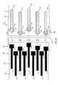
- FIG. 1Ais a schematic exploded view of an integrated circuit attached to a hybrid connector
- FIG. 1Bis a schematic assembled view of the integrated circuit attached to the connector, according to embodiments of the present invention
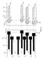
- FIGS. 2A , 2 B, and 2 Care respective perspective, side, and front schematic diagrams of the hybrid connector, according to embodiments of the present invention.
- FIG. 3is a schematic diagram illustrating a section of an integrated circuit and a section of a connector that connects to the integrated circuit, according to an alternative embodiment of the present invention
- FIG. 4is a schematic diagram illustrating a section of an integrated circuit and a section of a connector that connects to the integrated circuit, according to a further alternative embodiment of the present invention
- FIG. 5is a schematic diagram illustrating a section of an integrated circuit and a section of a connector that connects to the integrated circuit, according to a yet further alternative embodiment of the present invention.
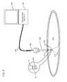
- FIG. 6is a schematic diagram illustrating an endoscope using a hybrid connector, according to an embodiment of the present invention.
- connection to an integrated circuit that reduces the space requirements of the connectionwould therefore be advantageous.
- An embodiment of the present inventionprovides an integrated circuit connector that uses space on the connector in an efficient manner.
- the connectorherein also termed a hybrid connector, is formed on a dielectric substrate, which is typically planar and flexible.
- Wire bond terminalsare attached to one side of the substrate, the wire bond terminals being configured to connect, via wire bonds, to a first set of terminals of an integrated circuit.
- Solder bump terminalsare attached to a second side of the substrate, so as to be insulated from the wire bond terminals.
- the solder bump terminalsare coupled, via respective solder balls, to a second set of terminals of the integrated circuit.
- the two sets of terminalsare arranged in congruent configurations.
- each wire bond terminalis “opposite” a respective solder bump terminal.
- the two types of terminalsmay be aligned so that each wire bond terminal is “opposite” a respective solder bump terminal.
- Such a configurationleads to an efficient use of space on the hybrid connector. For example, if the separation between adjacent wire bond terminals, and between adjacent solder bump terminals, is 60 ⁇ m, then the connector has two terminals in a pitch of 60 ⁇ m.
- inventions of the present inventionare advantageous in a number of fields, for example in the field of invasive or minimally invasive medical procedures where electronic equipment may need to be inserted into a patient.
- an endoscopemay need to be inserted into the patient, so that incorporating a hybrid connector, as is described herein, enables improved miniaturization of the endoscope, with consequent benefit to the patient.
- FIG. 1Ais a schematic exploded view of an integrated circuit (IC) 10 attached to a hybrid connector 12
- FIG. 1Bis a schematic assembled view of the IC attached to the connector, according to embodiments of the present invention.
- IC 10is typically constructed as a die on an insulating substrate 14 , and there are a number of conducting traces 16 leading from the die to generally similar IC conducting terminals 18 at the edge of the substrate.
- the IC conducting terminals at the edge of the substrateare used, as is explained further below, to connect elements of the die to components external to substrate 14 .
- the connectionis via hybrid connector 12 .
- FIGS. 1A and 1Bthe die to which traces 16 connect is not shown, and the diagram illustrates the edge of IC 10 .
- IC conducting terminals 18are assumed to be formed on an upper surface 20 of the substrate as a first row 22 and as a second row 24 .
- rows 22 and 24are rectilinear, i.e., are in a straight line, for simplicity of manufacture of IC 10 , and this configuration is assumed in the following description, except where otherwise stated.
- rows 22 and 24be rectilinear, and in some embodiments of the present invention at least one of the rows is non-rectilinear.
- hybrid connector 12For simplicity, the following description relates to a section 30 of hybrid connector 12 which corresponds with IC 10 having four conducting terminals 18 in each of rows 22 and 24 , but those having ordinary skill in the art will be able to adapt the following description for IC 10 with eight conducting terminals in each row, or for an IC with any convenient number of terminals in each row. While some elements of hybrid connector 12 are identified numerically in FIGS. 1A and 1B , for clarity the explanation of these elements is left to the description provided for FIGS. 2A , 2 B, and 2 C below.
- FIGS. 2A , 2 B, and 2 Care schematic views of section 30 of hybrid connector 12 , according to embodiments of the present invention.
- FIG. 2Ais a schematic perspective view
- FIG. 2Bis a schematic side view
- FIG. 2Cis a schematic front view of section 30 .
- Hybrid connectoris assumed to be formed with an insulating, dielectric, substrate 40 which is in the form of a parallelepiped having an upper surface 42 , a lower surface 44 , a front surface 46 , and a side surface 48 .
- the designations upper, lower, front, and sideare for clarity for use with the figures, and it will be understood that connector 12 may be used in substantially any orientation.
- substrate 40is a flexible substrate.
- Substantially similar wire bond conducting terminals 50are formed on upper surface 42 and the terminals are connected to respective conducting traces 52 ; four terminals 50 connected to four traces 52 are illustrated for section 30 .
- terminals 50are assumed to be rectangular.
- solder bump conducting terminals 60are formed on lower surface 44 , and the solder bump terminals are connected to respective conducting traces 62 ; four terminals 60 connected to four traces 62 are illustrated for section 30 .
- terminals 60are assumed to be circular.
- Solder ballsare also known as solder bumps or solder dots.
- Solder bump terminals 60are arranged on surface 44 so as to correspond in number and geometrical configuration with conducting terminals 18 in row 24 . Thus, in section 30 four solder bump terminals 60 are arranged along a straight line row 66 with spacing p between the terminals.
- Traces 52 and 62are typically connected, at the opposite ends of the traces to wire bond terminals 50 and solder bump terminals 60 , to equipment that uses IC 10 .
- the connectionmay be directly to the equipment, or alternatively via cabling connected between the opposite ends of the traces and the equipment.
- the cabling and the equipmentis not shown in FIGS. 1A , 1 B, 2 A, 2 B, and 2 C.
- substrate 40is positioned so that solder balls 64 align with and contact conducting terminals 18 of row 24 of the integrated circuit.
- the solder ballsmay then be re-melted to produce an electrical connection, typically using an ultrasonic or alternatively a reflow solder process. Space remaining between the lower surface 44 of the connector, and upper surface 20 of the IC may then typically be filled with an electrically-insulating adhesive, which provides a better mechanical connection between IC 10 and connector 12 than just the re-melted solder balls.
- terminals 50 of the hybrid connectorare then connected to respective IC terminals 18 in row 22 , using wire bonds 80 .
- wire bond terminals 50correspond in number to the number of solder bump terminals 60 .
- the wire bond terminalsare usually aligned with the solder bump terminals, since the correspondence in number and alignment leads to an efficient use of the space available in connector 12 .
- Such an efficient use of spaceis illustrated in FIGS. 2A , 2 B, and 2 C.
- Such an arrangementprovides two traces 52 , 62 per 60 ⁇ m, measured in a direction orthogonal to the traces.
- the number of wire bond terminals 50 on connector 12corresponds to the number of wire bond terminals 18 in row 22 of IC 10 , there is no requirement that there is a correspondence between the number of wire bond terminals 50 and solder bump terminals 60 . In connector 12 there is also no requirement that wire bond terminals 50 and solder bump terminals 60 are aligned. Thus, in some embodiments of the present invention the number of wire bond terminals 50 does not equal the number of solder bump terminals 60 , and/or the two sets of terminals are misaligned.
- solder bump terminals 60 of connector 12are arranged in a rectilinear manner, i.e., in a straight line, and that adjacent terminals are equally spaced along the line.
- the same arrangement, i.e., equally spaced in a straight line,is assumed for terminals 18 in row 24 of IC 10 .
- such a straight line, equally spaced arrangementis not a requirement for embodiments of the present invention, and examples of other possible arrangements of solder bump terminals 60 and terminals 18 of row 24 are described below.
- FIG. 3is a schematic diagram illustrating a section of an IC 110 , and a section of a connector 112 that connects to IC 110 , according to an embodiment of the present invention.
- the operations of IC 110 and connector 112are generally similar to those of IC 10 and connector 12 ( FIGS. 1A , 1 B, 2 A, 2 B, and 2 C), and elements indicated by the same reference numerals in ICs 110 and 10 , and in connectors 112 and 12 are generally similar in construction and in operation.
- FIG. 3only shows a portion of upper surface 20 of IC 110 , and a corresponding portion of lower surface 44 of substrate 40 of connector 112 .
- FIG. 1The figure is drawn from the point of view of a person looking at the IC 110 and connector 112 from above, so that elements on upper surface 20 are above the plane of the paper, whereas elements on lower surface 44 are “beneath” connector 112 , i.e., are below the plane of the paper. For clarity, in the illustration of connector 112 , only elements on lower surface 44 of the connector are shown.
- IC 110In IC 110 upper surface 20 has first row of terminals 22 , comprising conducting terminals 18 connected to respective traces 16 .
- IC 110comprises a second row 124 of terminals 18 , wherein, in contrast to row 24 of IC 10 , the terminals are arranged along a curved line 114 A.
- terminals 18 that are arranged along line 114 Aare equally spaced, and in the following description a spacing “q” between adjacent terminals of row 124 is assumed.
- Connector 112comprises a row 166 of solder bump terminals 60 connected to traces 62 , and solder balls 64 are mounted on terminals 60 .
- solder bump terminals 60 in row 166are arranged along a curved line 114 B which is congruent to curved line 114 A.
- the arrangement of the solder bump terminals 60 along line 114 Bis congruent to the arrangement of terminals 18 along line 114 A, so that terminals 60 in row 166 have spacing q between adjacent terminals 60 .
- solder balls 64 in row 166align with and contact conducting terminals 18 of row 124 of IC 110 .
- the solder ballsare then re-melted to form an electrical connection between terminals 18 and terminals 60 .
- FIG. 4is a schematic diagram illustrating a section of an IC 210 , and a section of a connector 212 that connects to IC 210 , according to an embodiment of the present invention.
- the operations of IC 210 and connector 212are generally similar to those of IC 10 and connector 12 ( FIGS. 1A , 1 B, 2 A, 2 B, 2 C, and 3 ), and elements indicated by the same reference numerals in ICs 210 and 10 , and in connectors 212 and 12 are generally similar in construction and in operation.
- IC 210 and connector 212The illustration of IC 210 and connector 212 is generally as for IC 110 and connector 112 ( FIG. 3 ), so that IC 210 and connector 212 are drawn from the point of view of a person looking at IC 210 and connector 212 from above. As for FIG. 3 , in FIG. 4 in the illustration of connector 212 , only elements on lower surface 44 of the connector are shown.
- IC 210In IC 210 upper surface 20 has first row of terminals 22 , comprising conducting terminals 18 connected to respective traces 16 .
- IC 210comprises a second row 224 of terminals 18 , which, in contrast to row 24 of IC 10 (and row 124 of IC 110 ), has terminals that are arranged along an irregular “zig-zag” line 214 A.
- terminals 18are arranged to be equally spaced if measured along a line 216 , orthogonal to traces 16 , and in the following description a spacing “r” along line 216 is assumed.
- Connector 212comprises a row 266 of solder bump terminals 60 connected to traces 62 , and solder balls 64 are mounted on terminals 60 .
- solder bump terminals 60 in row 266are arranged along an irregular line 214 B which is congruent to irregular line 214 A.
- the arrangement of solder bump terminals 60 along line 214 Bis congruent to the arrangement of terminals 18 along line 214 A, so that terminals 60 in row 266 have spacing r measured with respect to line 216 .
- solder balls 64 in row 266align with and contact conducting terminals 18 of row 224 of IC 110 .
- the solder ballsare then re-melted to form an electrical connection between terminals 18 and terminals 60 .
- FIG. 5is a schematic diagram illustrating a section of an IC 310 , and a section of a connector 312 that connects to IC 310 , according to an embodiment of the present invention.
- the operations of IC 310 and connector 312are generally similar to those of IC 10 and connector 12 ( FIGS. 1A , 1 B, 2 A, 2 B, and 2 C), and elements indicated by the same reference numerals in ICs 310 and 10 , and in connectors 312 and 12 are generally similar in construction and in operation.
- IC 310 and connector 312is generally as for IC 110 and connector 112 ( FIG. 3 ), so that IC 310 and connector 312 are drawn from the point of view of a person looking at IC 310 and connector 312 from above.
- FIG. 5 in the illustration of connector 312only elements on lower surface 44 of the connector are shown.
- IC 310In IC 310 upper surface 20 has first row of terminals 22 , comprising conducting terminals 18 connected to respective traces 16 .
- IC 310comprises a second row 324 of terminals 18 , which are arranged along an irregular non-linear line 314 A.
- terminals 18In addition to being arranged on non-linear line 314 A, terminals 18 are arranged to be unevenly spaced between adjacent terminals 18 .
- Connector 312comprises a row 366 of solder bump terminals 60 connected to traces 62 , and solder balls 64 are mounted on terminals 60 .
- Solder bump terminals 60 in row 366are arranged along an irregular non-linear line 314 B which is congruent to irregular non-linear line 314 A.
- the arrangement of solder bump terminals 60 along line 314 Bis congruent to the arrangement of terminals 18 along line 314 A. Consequently, the different spacings between adjacent bump terminals 60 are congruent to the different spacings between adjacent terminals 18 .
- connector 312 to IC 310is substantially as described above for attaching connector 212 to IC 210 .
- FIG. 6is a schematic diagram illustrating an endoscope 400 using a hybrid connector, according to an embodiment of the present invention.
- endoscope 400is assumed to use hybrid connector 12 connected to IC 10 (described above), and those having ordinary skill in the art will be able to adapt the description for other embodiments of the present invention, such as hybrid connectors 112 , 212 , and 312 , and integrated circuits other than IC 10 .
- Imaging device 402is formed on IC 10 , the imaging device typically comprising a CCD (charge coupled device) which acquires an image of an object viewed using the endoscope.
- Imaging device 402typically includes corresponding optics, but for simplicity the optics are not illustrated in FIG. 6 .
- Imaging device 402is located at a distal end 404 of the endoscope, and the distal end is inserted, via a trocar 406 into a body cavity 408 of a patient, so that device 402 acquires an image of walls 410 of the patient's body cavity.
- hybrid connector 12Also located at distal end 404 is hybrid connector 12 , which connects to IC 10 , as described above, and the traces of the hybrid connector connect (at the opposite ends of the traces from terminals 50 and 60 ) to endoscope cabling 420 .
- hybrid connector 12allows the diameter of distal end 404 to be reduced compared to distal ends of prior art endoscopes, and the reduced diameter is beneficial to the patient whose body cavity is being imaged.
- An endoscope module 430is connected to cabling 420 , the module serving to provide power and driving signals to IC 10 and imaging device 402 via the cabling and hybrid connector 12 .
- the modulealso receives image signals from device 402 via the cabling and the hybrid connector, and the module processes the signals so as to display an image of walls 410 on a screen 440 .
- Endoscope modulessuch as module 430 are well known in the art, and for simplicity will not further be described here.
Landscapes
- Health & Medical Sciences (AREA)
- Life Sciences & Earth Sciences (AREA)
- Surgery (AREA)
- Engineering & Computer Science (AREA)
- Medical Informatics (AREA)
- General Health & Medical Sciences (AREA)
- Pathology (AREA)
- Radiology & Medical Imaging (AREA)
- Nuclear Medicine, Radiotherapy & Molecular Imaging (AREA)
- Biophysics (AREA)
- Biomedical Technology (AREA)
- Heart & Thoracic Surgery (AREA)
- Physics & Mathematics (AREA)
- Molecular Biology (AREA)
- Animal Behavior & Ethology (AREA)
- Optics & Photonics (AREA)
- Public Health (AREA)
- Veterinary Medicine (AREA)
- Microelectronics & Electronic Packaging (AREA)
- Computer Hardware Design (AREA)
- Power Engineering (AREA)
- Multimedia (AREA)
- Signal Processing (AREA)
- Endoscopes (AREA)
- Coupling Device And Connection With Printed Circuit (AREA)
- Instruments For Viewing The Inside Of Hollow Bodies (AREA)
Abstract
Description
The present invention relates generally to connection devices, and specifically to devices where space used is a premium.
Space requirements in the field of integrated circuit utilization are a critical feature of the design of a system using integrated circuits. The smaller that an integrated circuit, and ancillary components such as conducting traces to the integrated circuit, can be made, the more integrated circuits can be produced for a given size of a silicon wafer. Other advantages for reduced size integrated circuits include the reduction in power requirements for operating the circuits.
An embodiment of the present invention provides a connector for connection to terminals of an integrated circuit, the connector including:
a dielectric substrate having a first side and a second side;
wire bond terminals, attached to the first side of the substrate and configured to receive wire bonds connected to a first set of the terminals of the integrated circuit; and
solder bump terminals, attached to the second side of the substrate so as to be insulated from the wire bond terminals, the solder bump terminals being configured to be coupled via solder balls with a second set of the terminals of the integrated circuit.
Typically, the solder bump terminals are arranged in a solder bump terminal configuration, and the second set of terminals of the integrated circuit are arranged in an integrated circuit terminal configuration which is congruent to the solder bump terminal configuration. In an embodiment, solder bump terminal configuration is rectilinear. Alternatively, the solder bump terminal configuration is non-rectilinear.
In a disclosed embodiment the solder bump terminals are equally spaced. Alternatively, the solder bump terminals are unevenly spaced.
In a further disclosed embodiment the wire bond terminals and the solder bump terminals are equal in number. Typically, the wire bond terminals and the solder bump terminals are aligned.
In a yet further disclosed embodiment the wire bond terminals and the solder bump terminals are misaligned.
There is further provided, according to an embodiment of the present invention embodiment, a method for connecting to terminals of an integrated circuit, the method including:
providing a dielectric substrate having a first side and a second side;
attaching wire bond terminals to the first side of the substrate, the wire bond terminals being configured to receive wire bonds connected to a first set of the terminals of the integrated circuit; and
attaching solder bump terminals to the second side of the substrate so as to be insulated from the wire bond terminals, the solder bump terminals being configured to be coupled via solder balls with a second set of the terminals of the integrated circuit.
There is further provided, according to an embodiment of the present invention, an endoscope, including:
an integrated circuit;
an imaging device formed on the integrated circuit; and
a connector for connection to terminals of the integrated circuit, the connector including:
a dielectric substrate having a first side and a second side;
wire bond terminals, attached to the first side of the substrate and configured to receive wire bonds connected to a first set of the terminals of the integrated circuit; and
solder bump terminals, attached to the second side of the substrate so as to be insulated from the wire bond terminals, the solder bump terminals being configured to be coupled via solder balls with a second set of the terminals of the integrated circuit.
There is further provided, according to an embodiment of the present invention, a method for forming an endoscope, including:
providing an integrated circuit having terminals;
implementing an imaging device on the integrated circuit;
attaching wire bond terminals to a first side of a dielectric substrate, the wire bond terminals being configured to receive wire bonds connected to a first set of the terminals of the integrated circuit; and
attaching solder bump terminals to a second side of the dielectric substrate so as to be insulated from the wire bond terminals, the solder bump terminals being configured to be coupled via solder balls with a second set of the terminals of the integrated circuit.
The present invention will be more fully understood from the following detailed description of the embodiments thereof, taken together with the drawings in which:
In certain fields, such as invasive medical procedures, miniaturization of the equipment used is extremely beneficial. There is thus constant pressure to reduce the size of the elements of integrated circuits, including connections to the circuits.
A connection to an integrated circuit that reduces the space requirements of the connection would therefore be advantageous.
An embodiment of the present invention provides an integrated circuit connector that uses space on the connector in an efficient manner. The connector, herein also termed a hybrid connector, is formed on a dielectric substrate, which is typically planar and flexible. Wire bond terminals are attached to one side of the substrate, the wire bond terminals being configured to connect, via wire bonds, to a first set of terminals of an integrated circuit. Solder bump terminals are attached to a second side of the substrate, so as to be insulated from the wire bond terminals. The solder bump terminals are coupled, via respective solder balls, to a second set of terminals of the integrated circuit. Typically, in order for the solder bump terminals to couple to the second set of integrated circuit terminals, the two sets of terminals are arranged in congruent configurations.
Typically, although not necessarily, there are an equal number of wire bond terminals and solder bump terminals, and the two types of terminals may be aligned so that each wire bond terminal is “opposite” a respective solder bump terminal. Such a configuration leads to an efficient use of space on the hybrid connector. For example, if the separation between adjacent wire bond terminals, and between adjacent solder bump terminals, is 60 μm, then the connector has two terminals in a pitch of 60 μm.
The reduction in space requirements provided by embodiments of the present invention is advantageous in a number of fields, for example in the field of invasive or minimally invasive medical procedures where electronic equipment may need to be inserted into a patient. As a specific example, in a minimally invasive procedure an endoscope may need to be inserted into the patient, so that incorporating a hybrid connector, as is described herein, enables improved miniaturization of the endoscope, with consequent benefit to the patient.
In an embodiment of the present invention,IC conducting terminals 18 are assumed to be formed on anupper surface 20 of the substrate as afirst row 22 and as asecond row 24. Typically,rows IC 10, and this configuration is assumed in the following description, except where otherwise stated. However, there is no requirement thatrows FIGS. 1A and 1B there are assumed to be eight conducting terminals in each row, the rows are assumed to be rectilinear, and there is a separation p between adjacent terminals within a row. However, it will be understood that embodiments of the present invention may be implemented for any convenient number of terminals in each row.
For simplicity, the following description relates to asection 30 ofhybrid connector 12 which corresponds withIC 10 having four conductingterminals 18 in each ofrows IC 10 with eight conducting terminals in each row, or for an IC with any convenient number of terminals in each row. While some elements ofhybrid connector 12 are identified numerically inFIGS. 1A and 1B , for clarity the explanation of these elements is left to the description provided forFIGS. 2A ,2B, and2C below.
Substantially similar wirebond conducting terminals 50 are formed onupper surface 42 and the terminals are connected to respective conducting traces52; fourterminals 50 connected to fourtraces 52 are illustrated forsection 30. By way of example,terminals 50 are assumed to be rectangular.
Substantially similar solderbump conducting terminals 60 are formed onlower surface 44, and the solder bump terminals are connected to respective conducting traces62; fourterminals 60 connected to fourtraces 62 are illustrated forsection 30. By way of example,terminals 60 are assumed to be circular. To each solder bump conducting terminal60 arespective solder ball 64 is attached. Solder balls are also known as solder bumps or solder dots.
Returning toFIGS. 1A and 1B , to attachconnector 12 toIC 10,substrate 40 is positioned so thatsolder balls 64 align with andcontact conducting terminals 18 ofrow 24 of the integrated circuit. The solder balls may then be re-melted to produce an electrical connection, typically using an ultrasonic or alternatively a reflow solder process. Space remaining between thelower surface 44 of the connector, andupper surface 20 of the IC may then typically be filled with an electrically-insulating adhesive, which provides a better mechanical connection betweenIC 10 andconnector 12 than just the re-melted solder balls.
To complete the connection betweenIC 10 andconnector 12,terminals 50 of the hybrid connector are then connected torespective IC terminals 18 inrow 22, usingwire bonds 80.
Typically,wire bond terminals 50 correspond in number to the number ofsolder bump terminals 60. In addition, the wire bond terminals are usually aligned with the solder bump terminals, since the correspondence in number and alignment leads to an efficient use of the space available inconnector 12. Such an efficient use of space is illustrated inFIGS. 2A ,2B, and2C. In one embodiment, the wire bond terminals and the solder bump terminals are aligned, and p=60 μm. Such an arrangement provides twotraces
However, while the number ofwire bond terminals 50 onconnector 12 corresponds to the number ofwire bond terminals 18 inrow 22 ofIC 10, there is no requirement that there is a correspondence between the number ofwire bond terminals 50 andsolder bump terminals 60. Inconnector 12 there is also no requirement thatwire bond terminals 50 andsolder bump terminals 60 are aligned. Thus, in some embodiments of the present invention the number ofwire bond terminals 50 does not equal the number ofsolder bump terminals 60, and/or the two sets of terminals are misaligned.
The embodiments described above have assumed thatsolder bump terminals 60 ofconnector 12 are arranged in a rectilinear manner, i.e., in a straight line, and that adjacent terminals are equally spaced along the line. The same arrangement, i.e., equally spaced in a straight line, is assumed forterminals 18 inrow 24 ofIC 10. However, such a straight line, equally spaced arrangement is not a requirement for embodiments of the present invention, and examples of other possible arrangements ofsolder bump terminals 60 andterminals 18 ofrow 24 are described below.
InIC 110upper surface 20 has first row ofterminals 22, comprising conductingterminals 18 connected to respective traces16.IC 110 comprises asecond row 124 ofterminals 18, wherein, in contrast to row24 ofIC 10, the terminals are arranged along acurved line 114A. Typically, although not necessarily,terminals 18 that are arranged alongline 114A are equally spaced, and in the following description a spacing “q” between adjacent terminals ofrow 124 is assumed.
As forconnector 12 andIC 10, in attachingconnector 112 toIC 110substrate 40 is positioned so thatsolder balls 64 inrow 166 align with andcontact conducting terminals 18 ofrow 124 ofIC 110. The solder balls are then re-melted to form an electrical connection betweenterminals 18 andterminals 60.
The illustration ofIC 210 andconnector 212 is generally as forIC 110 and connector112 (FIG. 3 ), so thatIC 210 andconnector 212 are drawn from the point of view of a person looking atIC 210 andconnector 212 from above. As forFIG. 3 , inFIG. 4 in the illustration ofconnector 212, only elements onlower surface 44 of the connector are shown.
InIC 210upper surface 20 has first row ofterminals 22, comprising conductingterminals 18 connected to respective traces16.IC 210 comprises asecond row 224 ofterminals 18, which, in contrast to row24 of IC10 (and row124 of IC110), has terminals that are arranged along an irregular “zig-zag”line 214A. Typically, although not necessarily,terminals 18 are arranged to be equally spaced if measured along aline 216, orthogonal totraces 16, and in the following description a spacing “r” alongline 216 is assumed.
To attachconnector 212 toIC 210substrate 40 is positioned so thatsolder balls 64 inrow 266 align with andcontact conducting terminals 18 ofrow 224 ofIC 110. The solder balls are then re-melted to form an electrical connection betweenterminals 18 andterminals 60.
The illustration ofIC 310 andconnector 312 is generally as forIC 110 and connector112 (FIG. 3 ), so thatIC 310 andconnector 312 are drawn from the point of view of a person looking atIC 310 andconnector 312 from above. InFIG. 5 in the illustration ofconnector 312, only elements onlower surface 44 of the connector are shown.
InIC 310upper surface 20 has first row ofterminals 22, comprising conductingterminals 18 connected to respective traces16.IC 310 comprises asecond row 324 ofterminals 18, which are arranged along an irregularnon-linear line 314A. In addition to being arranged onnon-linear line 314A,terminals 18 are arranged to be unevenly spaced betweenadjacent terminals 18.
The attachment ofconnector 312 toIC 310 is substantially as described above for attachingconnector 212 toIC 210.
Animaging device 402 is formed onIC 10, the imaging device typically comprising a CCD (charge coupled device) which acquires an image of an object viewed using the endoscope. (Imaging device 402 typically includes corresponding optics, but for simplicity the optics are not illustrated inFIG. 6 .)Imaging device 402 is located at adistal end 404 of the endoscope, and the distal end is inserted, via atrocar 406 into abody cavity 408 of a patient, so thatdevice 402 acquires an image ofwalls 410 of the patient's body cavity. Also located atdistal end 404 ishybrid connector 12, which connects toIC 10, as described above, and the traces of the hybrid connector connect (at the opposite ends of the traces fromterminals 50 and60) toendoscope cabling 420.
The miniaturization provided byhybrid connector 12 allows the diameter ofdistal end 404 to be reduced compared to distal ends of prior art endoscopes, and the reduced diameter is beneficial to the patient whose body cavity is being imaged.
Anendoscope module 430 is connected to cabling420, the module serving to provide power and driving signals toIC 10 andimaging device 402 via the cabling andhybrid connector 12. The module also receives image signals fromdevice 402 via the cabling and the hybrid connector, and the module processes the signals so as to display an image ofwalls 410 on ascreen 440. Endoscope modules such asmodule 430 are well known in the art, and for simplicity will not further be described here.
While the above description refers to use of a hybrid connector in an endoscope, it will be understood that the reduced size provided by embodiments of the present invention may be advantageously implemented in other fields, such as, but not being limited to, non-medical fields where size reduction of components is important. It will thus be appreciated that the embodiments described above are cited by way of example, and that the present invention is not limited to what has been particularly shown and described hereinabove. Rather, the scope of the present invention includes both combinations and subcombinations of the various features described hereinabove, as well as variations and modifications thereof which would occur to persons skilled in the art upon reading the foregoing description and which are not disclosed in the prior art.
Claims (9)
1. Apparatus, comprising:
an integrated circuit comprising a first set of terminals and a second set of terminals:
wire bonds connected to the first set of terminals; and
a connector connected to the integrated circuit, the connector comprising:
a dielectric substrate having a first side and a second side;
wire bond terminals, attached to the first side of the substrate, that receive the wire bonds; and
solder bump terminals, attached to the second side of the substrate so as to be insulated from the wire bond terminals, and coupled via solder balls with the second set of terminals of the integrated circuit, wherein the solder bump terminals are arranged in a solder bump terminal configuration, and the second set of terminals of the integrated circuit are arranged in an integrated circuit terminal configuration which is congruent to the solder bump terminal configuration.
2. The apparatus according toclaim 1 , wherein the solder bump terminal configuration is rectilinear.
3. The apparatus according toclaim 1 , wherein the solder bump terminal configuration is non-rectilinear.
4. The apparatus according toclaim 1 , wherein the solder bump terminals are equally spaced.
5. The apparatus according toclaim 1 , wherein the solder bump terminals are unevenly spaced.
6. The apparatus according toclaim 1 , wherein the wire bond terminals and the solder bump terminals are equal in number.
7. The apparatus according toclaim 6 , wherein the wire bond terminals and the solder bump terminals are aligned, such that each wire bond terminal is opposite a respective solder bump terminal.
8. The apparatus according toclaim 6 , wherein the wire bond terminals and the solder bump terminals are misaligned.
9. An endoscope, comprising:
an integrated circuit comprising a first set of terminals and a second set of terminals;
wire bonds connected to the first set of terminals;
an imaging device formed on the integrated circuit; and
a connector connected the integrated circuit, the connector comprising:
a dielectric substrate having a first side and a second side;
wire bond terminals, attached to the first side of the substrate, that receive the wire bonds; and
solder bump terminals, attached to the second side of the substrate so as to be insulated from the wire bond terminals coupled via solder balls with the second set of terminals of the integrated circuit, wherein the solder bump terminals are arranged in a solder bump terminal configuration, and the second set of terminals of the integrated circuit are arranged in an integrated circuit terminal configuration which is congruent to the solder bump terminal configuration.
Priority Applications (5)
| Application Number | Priority Date | Filing Date | Title |
|---|---|---|---|
| US13/933,145US9257763B2 (en) | 2013-07-02 | 2013-07-02 | Hybrid interconnect |
| JP2015563153AJP2016528933A (en) | 2013-07-02 | 2014-06-18 | Hybrid interconnect |
| CN201480032495.4ACN105265028B (en) | 2013-07-02 | 2014-06-18 | Mixing interconnection |
| EP14737123.1AEP3017665B1 (en) | 2013-07-02 | 2014-06-18 | Hybrid interconnect |
| PCT/US2014/042825WO2015002735A1 (en) | 2013-07-02 | 2014-06-18 | Hybrid interconnect |
Applications Claiming Priority (1)
| Application Number | Priority Date | Filing Date | Title |
|---|---|---|---|
| US13/933,145US9257763B2 (en) | 2013-07-02 | 2013-07-02 | Hybrid interconnect |
Publications (2)
| Publication Number | Publication Date |
|---|---|
| US20150011832A1 US20150011832A1 (en) | 2015-01-08 |
| US9257763B2true US9257763B2 (en) | 2016-02-09 |
Family
ID=51162962
Family Applications (1)
| Application Number | Title | Priority Date | Filing Date |
|---|---|---|---|
| US13/933,145Active2033-12-31US9257763B2 (en) | 2013-07-02 | 2013-07-02 | Hybrid interconnect |
Country Status (5)
| Country | Link |
|---|---|
| US (1) | US9257763B2 (en) |
| EP (1) | EP3017665B1 (en) |
| JP (1) | JP2016528933A (en) |
| CN (1) | CN105265028B (en) |
| WO (1) | WO2015002735A1 (en) |
Cited By (1)
| Publication number | Priority date | Publication date | Assignee | Title |
|---|---|---|---|---|
| US11818839B2 (en)* | 2018-05-15 | 2023-11-14 | Samsung Display Co., Ltd. | Display panel and display device including the same having pads with inclinations with respect to reference lines |
Families Citing this family (1)
| Publication number | Priority date | Publication date | Assignee | Title |
|---|---|---|---|---|
| US20240298412A1 (en)* | 2023-03-03 | 2024-09-05 | Aac Microtech (Changzhou) Co., Ltd. | Circuit board |
Citations (200)
| Publication number | Priority date | Publication date | Assignee | Title |
|---|---|---|---|---|
| US3321656A (en) | 1954-03-11 | 1967-05-23 | Edward E Sheldon | Television camera tube with lead oxide screen |
| GB1215383A (en) | 1968-02-27 | 1970-12-09 | Olympus Optical Co | Optical viewing instrument |
| US3971065A (en) | 1975-03-05 | 1976-07-20 | Eastman Kodak Company | Color imaging array |
| US4253447A (en) | 1978-10-16 | 1981-03-03 | Welch Allyn, Inc. | Color endoscope with charge coupled device and television viewing |
| US4261344A (en) | 1979-09-24 | 1981-04-14 | Welch Allyn, Inc. | Color endoscope |
| US4278077A (en) | 1978-07-27 | 1981-07-14 | Olympus Optical Co., Ltd. | Medical camera system |
| US4429328A (en) | 1981-07-16 | 1984-01-31 | Cjm Associates | Three-dimensional display methods using vertically aligned points of origin |
| US4467361A (en) | 1981-08-14 | 1984-08-21 | Olympus Optical Co., Ltd. | Image pick-up apparatus |
| US4491865A (en) | 1982-09-29 | 1985-01-01 | Welch Allyn, Inc. | Image sensor assembly |
| US4555768A (en) | 1983-06-07 | 1985-11-26 | Rca Corporation | Digital signal processing system employing logarithms to multiply and divide |
| US4569335A (en) | 1983-04-12 | 1986-02-11 | Sumitomo Electric Industries, Ltd. | Fiberscope |
| US4573450A (en) | 1983-11-11 | 1986-03-04 | Fuji Photo Optical Co., Ltd. | Endoscope |
| US4576146A (en) | 1983-03-22 | 1986-03-18 | Sumitomo Electric Industries, Ltd. | Fiberscope |
| US4602281A (en) | 1983-09-05 | 1986-07-22 | Olympus Optical Co., Ltd. | Automatic means for controlling dosage of illuminating light for picking-up image by endoscope assembly |
| US4604992A (en) | 1983-12-27 | 1986-08-12 | Olympus Optical Company, Ltd. | Endoscope system |
| US4622954A (en) | 1984-05-15 | 1986-11-18 | Fuji Photo Optical Co., Ltd. | Endoscope having a plate-like image sensor for forming images |
| US4625236A (en) | 1984-07-31 | 1986-11-25 | Olympus Optical Co., Ltd. | Light source means for endoscope employing solid state imaging device |
| US4633304A (en) | 1983-08-27 | 1986-12-30 | Olympus Optical Co., Ltd. | Endoscope assembly |
| US4643170A (en) | 1984-12-05 | 1987-02-17 | Olympus Optical Co., Ltd. | Endoscope apparatus |
| US4646721A (en) | 1984-06-26 | 1987-03-03 | Fuji Photo Optical Co., Ltd. | Light shielding construction for the forward end of an endoscope |
| US4651201A (en) | 1984-06-01 | 1987-03-17 | Arnold Schoolman | Stereoscopic endoscope arrangement |
| US4656508A (en) | 1984-06-08 | 1987-04-07 | Olympus Optical Co., Ltd. | Measuring endoscope |
| US4682219A (en) | 1985-08-16 | 1987-07-21 | Fuji Photo Optical Co., Ltd. | Endoscope |
| US4684222A (en) | 1984-05-30 | 1987-08-04 | Corning Glass Works | Small anamorphic lenses and method |
| US4692608A (en) | 1984-05-18 | 1987-09-08 | Fuji Photo Optical Company, Ltd. | Compact optical imaging system |
| US4697208A (en) | 1985-06-13 | 1987-09-29 | Olympus Optical Co., Ltd. | Color image pickup device with complementary color type mosaic filter and gamma compensation means |
| US4713683A (en) | 1984-08-31 | 1987-12-15 | Olympus Optical Co., Ltd. | Illuminating and synchronizing device for color imaging equipment |
| US4714319A (en) | 1983-09-30 | 1987-12-22 | Zeevi Yehoshua Y | Apparatus for relief illusion |
| US4720178A (en) | 1984-08-15 | 1988-01-19 | Olympus Optical Co., Ltd. | Optical system for endoscope |
| US4741327A (en) | 1986-04-30 | 1988-05-03 | Olympus Optical Co., Ltd. | Endoscope having bent circuit board |
| US4746203A (en) | 1984-08-15 | 1988-05-24 | Olympus Optical Co., Ltd. | Optical system for endoscope |
| US4757805A (en) | 1986-06-25 | 1988-07-19 | Olympus Optical Co., Ltd. | Endoscope |
| US4768513A (en) | 1986-04-21 | 1988-09-06 | Agency Of Industrial Science And Technology | Method and device for measuring and processing light |
| US4784133A (en) | 1987-01-28 | 1988-11-15 | Mackin Robert A | Working well balloon angioscope and method |
| US4803562A (en) | 1986-06-20 | 1989-02-07 | Olympus Optical Co., Ltd. | Image sensing apparatus |
| US4803550A (en) | 1987-04-17 | 1989-02-07 | Olympus Optical Co., Ltd. | Imaging apparatus having illumination means |
| US4809680A (en) | 1986-09-01 | 1989-03-07 | Olympus Optical Co., Ltd. | Endoscope tip |
| US4819065A (en) | 1986-05-08 | 1989-04-04 | Olympus Optical Co., Ltd. | Electronic endoscope apparatus |
| US4827909A (en) | 1987-03-31 | 1989-05-09 | Kabushiki Kaisha Toshiba | Endoscopic apparatus |
| US4827907A (en) | 1986-11-28 | 1989-05-09 | Teac Optical Co., Ltd. | Intra-observation apparatus |
| US4831456A (en) | 1986-12-08 | 1989-05-16 | Olympus Optical Co., Ltd. | Imaging apparatus using a solid-state imaging element having a substrate |
| US4832033A (en) | 1985-04-29 | 1989-05-23 | Bio-Medical Research Limited | Electrical stimulation of muscle |
| US4832003A (en) | 1986-09-12 | 1989-05-23 | Olympus Optical Co., Ltd. | Electronic endoscope tip |
| US4857724A (en) | 1987-05-15 | 1989-08-15 | U.S. Philips Corp. | Picture pick-up and display system and picture pick-up device suitable for said system |
| US4862873A (en) | 1987-05-27 | 1989-09-05 | Olympus Optical Co., Ltd. | Stereo endoscope |
| US4866526A (en) | 1987-07-25 | 1989-09-12 | Richard Wolf Gmbh | Video endoscope with light intensity regulation |
| US4869256A (en) | 1987-04-22 | 1989-09-26 | Olympus Optical Co., Ltd. | Endoscope apparatus |
| US4873572A (en) | 1987-02-27 | 1989-10-10 | Olympus Optical Co., Ltd. | Electronic endoscope apparatus |
| US4884133A (en) | 1987-06-11 | 1989-11-28 | Olympus Optical Co., Ltd. | Endoscope light source apparatus |
| US4905670A (en) | 1988-12-28 | 1990-03-06 | Adair Edwin Lloyd | Apparatus for cervical videoscopy |
| US4926257A (en) | 1986-12-19 | 1990-05-15 | Olympus Optical Co., Ltd. | Stereoscopic electronic endoscope device |
| US4934339A (en) | 1988-10-07 | 1990-06-19 | Olympus Optical Co., Ltd. | Intravascular endoscope apparatus |
| US4939573A (en) | 1983-03-17 | 1990-07-03 | Nec Corporation | Color filter arrangement comprising transparent or white filters for solid state color imaging apparatus |
| US4953539A (en) | 1986-12-26 | 1990-09-04 | Olympus Optical Co., Ltd. | Endoscope apparatus |
| US4967269A (en) | 1988-07-28 | 1990-10-30 | Olympus Optical Co., Ltd. | Endoscope automatic light control apparatus and endoscope apparatus making use of the same |
| US4986642A (en) | 1987-11-20 | 1991-01-22 | Olympus Optical Co., Ltd. | Objective lens system for endoscopes and image pickup system equipped with said objective lens system |
| US4998972A (en) | 1988-04-28 | 1991-03-12 | Thomas J. Fogarty | Real time angioscopy imaging system |
| US5021888A (en) | 1987-12-18 | 1991-06-04 | Kabushiki Kaisha Toshiba | Miniaturized solid state imaging device |
| US5022399A (en) | 1989-05-10 | 1991-06-11 | Biegeleisen Ken P | Venoscope |
| US5029574A (en) | 1988-04-14 | 1991-07-09 | Okamoto Industries, Inc. | Endoscopic balloon with a protective film thereon |
| US5122650A (en) | 1991-04-18 | 1992-06-16 | Mckinley Optics, Inc. | Stereo video endoscope objective lens system |
| US5166787A (en) | 1989-06-28 | 1992-11-24 | Karl Storz Gmbh & Co. | Endoscope having provision for repositioning a video sensor to a location which does not provide the same cross-sectionally viewed relationship with the distal end |
| US5184223A (en) | 1990-04-28 | 1993-02-02 | Olympus Optical Co., Ltd. | Electronic imaging apparatus |
| US5187572A (en) | 1990-10-31 | 1993-02-16 | Olympus Optical Co., Ltd. | Endoscope system with a plurality of synchronized light source apparatuses |
| US5191203A (en) | 1991-04-18 | 1993-03-02 | Mckinley Optics, Inc. | Stereo video endoscope objective lens system |
| US5216512A (en) | 1990-02-08 | 1993-06-01 | U.S. Philips Corp. | Imaging system including an optical system compressing a circular object plane area to an elliptical area at a detection face |
| US5219292A (en) | 1992-04-03 | 1993-06-15 | Motorola, Inc. | Printed circuit board interconnection |
| US5222477A (en) | 1991-09-30 | 1993-06-29 | Welch Allyn, Inc. | Endoscope or borescope stereo viewing system |
| US5233416A (en) | 1991-07-01 | 1993-08-03 | Fuji Photo Optical Co., Ltd. | Electronic endoscope system |
| US5264925A (en) | 1992-06-26 | 1993-11-23 | Life Surgery, Inc. | Single sensor video imaging system and method using sequential color object illumination |
| US5301090A (en) | 1992-03-16 | 1994-04-05 | Aharon Z. Hed | Luminaire |
| US5306541A (en) | 1990-03-13 | 1994-04-26 | Mitsubishi Denki Kabushiki Kaisha | Printed circuit board and terminal board with staggered conductive pads |
| US5311600A (en) | 1992-09-29 | 1994-05-10 | The Board Of Trustees Of The Leland Stanford Junior University | Method of edge detection in optical images using neural network classifier |
| US5323233A (en) | 1990-07-31 | 1994-06-21 | Canon Kabushiki Kaisha | Image signal processing apparatus having a color filter with offset luminance filter elements |
| US5325847A (en) | 1991-10-25 | 1994-07-05 | Asahi Kogaku Kogyo Kabushiki Kaisha | Distal end part of endoscope |
| US5335662A (en) | 1992-08-28 | 1994-08-09 | Olympus Optical Co., Ltd. | Image pickup system comprising signal processing device which uses exclusive adaptor in probes different in image pickup system from each other |
| US5343254A (en) | 1991-04-25 | 1994-08-30 | Olympus Optical Co., Ltd. | Image signal processing device capable of suppressing nonuniformity of illumination |
| US5363135A (en) | 1992-04-21 | 1994-11-08 | Inglese Jean Marc | Endoscope having a semi-conductor element illumination arrangement |
| US5376960A (en) | 1991-09-10 | 1994-12-27 | Richard Wolf Gmbh | Video endoscope with solid-state imaging device |
| US5408268A (en) | 1992-06-26 | 1995-04-18 | Apollo Camera, L.L.C. | Video imaging system and method using a single full frame sensor and sequential color object illumination |
| US5430475A (en) | 1990-06-29 | 1995-07-04 | Olympus Optical Co., Ltd. | Electronic endoscope apparatus having micro array on photoelectric conversion surface |
| US5432543A (en) | 1992-03-05 | 1995-07-11 | Olympus Optical Co., Ltd. | Endoscopic image processing device for estimating three-dimensional shape of object based on detection of same point on a plurality of different images |
| US5444574A (en) | 1991-09-19 | 1995-08-22 | Olympus Optical Co., Ltd. | Electronic image pickup apparatus equipped with means for eliminating moire |
| US5450243A (en) | 1987-02-25 | 1995-09-12 | Olympus Optical Co., Ltd. | Imaging system having a blurring optical element for minimizing moire phenomenon |
| US5471237A (en) | 1992-06-26 | 1995-11-28 | Apollo Camer, Llc | Single lens stereoscopic video camera |
| US5494483A (en) | 1992-09-30 | 1996-02-27 | Adair; Edwin L. | Stereoscopic endoscope with miniaturized electronic imaging chip |
| US5498230A (en) | 1994-10-03 | 1996-03-12 | Adair; Edwin L. | Sterile connector and video camera cover for sterile endoscope |
| US5512940A (en) | 1993-03-19 | 1996-04-30 | Olympus Optical Co., Ltd. | Image processing apparatus, endoscope image sensing and processing apparatus, and image processing method for performing different displays depending upon subject quantity |
| US5547455A (en) | 1994-03-30 | 1996-08-20 | Medical Media Systems | Electronically steerable endoscope |
| US5557324A (en) | 1992-10-29 | 1996-09-17 | The Johns Hopkins University | Polorization viewer |
| US5575754A (en) | 1995-02-24 | 1996-11-19 | Olympus Optical Co., Ltd. | Endoscopic apparatus for three dimensional instrumentation |
| US5588948A (en) | 1993-02-17 | 1996-12-31 | Olympus Optical Co. Ltd. | Stereoscopic endoscope |
| US5594497A (en) | 1993-04-07 | 1997-01-14 | Ahern; John M. | Endoscope provided with a distally located color CCD |
| US5598205A (en) | 1994-04-22 | 1997-01-28 | Olympus Optical Co., Ltd. | Imaging apparatus |
| US5604531A (en) | 1994-01-17 | 1997-02-18 | State Of Israel, Ministry Of Defense, Armament Development Authority | In vivo video camera system |
| US5603687A (en) | 1992-10-28 | 1997-02-18 | Oktas General Partnership | Asymmetric stereo-optic endoscope |
| US5607436A (en) | 1993-10-08 | 1997-03-04 | United States Surgical Corporation | Apparatus for applying surgical clips |
| JPH09173288A (en) | 1995-12-25 | 1997-07-08 | Fuji Photo Optical Co Ltd | Camera head device for electronic endoscope |
| US5668596A (en) | 1996-02-29 | 1997-09-16 | Eastman Kodak Company | Digital imaging device optimized for color performance |
| US5673147A (en) | 1995-04-18 | 1997-09-30 | Mckinley Optics, Inc. | Stereo video endoscope objective lens systems |
| US5700236A (en) | 1993-10-08 | 1997-12-23 | United States Surgical Corporation | Endoscope attachment for changing angle of view |
| US5712493A (en) | 1995-03-20 | 1998-01-27 | Kabushiki Kaisha Toshiba | Display device having driving circuits at the periphery of a substrate |
| US5728044A (en) | 1995-03-10 | 1998-03-17 | Shan; Yansong | Sensor device for spacial imaging of endoscopes |
| US5751341A (en) | 1993-01-05 | 1998-05-12 | Vista Medical Technologies, Inc. | Stereoscopic endoscope system |
| US5754280A (en) | 1995-05-23 | 1998-05-19 | Olympus Optical Co., Ltd. | Two-dimensional rangefinding sensor |
| US5784098A (en) | 1995-08-28 | 1998-07-21 | Olympus Optical Co., Ltd. | Apparatus for measuring three-dimensional configurations |
| US5792045A (en) | 1994-10-03 | 1998-08-11 | Adair; Edwin L. | Sterile surgical coupler and drape |
| US5797837A (en) | 1995-10-04 | 1998-08-25 | Fuji Photo Optical Co., Ltd. | Endoscope image unit with circuit board having a hole therethrough |
| US5819736A (en) | 1994-03-24 | 1998-10-13 | Sightline Technologies Ltd. | Viewing method and apparatus particularly useful for viewing the interior of the large intestine |
| US5827176A (en) | 1996-02-13 | 1998-10-27 | Fuji Photo Optical Co., Ltd. | Endoscopic imaging system with rotating photoelectric line sensor |
| WO1998048449A2 (en) | 1997-04-21 | 1998-10-29 | Flip Chip Technologies, L.L.C. | Flip chip and chip scale package |
| US5847394A (en) | 1995-12-18 | 1998-12-08 | Research Foundation Of City College Of New York | Imaging of objects based upon the polarization or depolarization of light |
| US5905597A (en) | 1994-10-20 | 1999-05-18 | Canon Kabushiki Kaisha | Optical apparatus |
| US5907178A (en) | 1996-01-29 | 1999-05-25 | International Business Machines Corporation | Multi-view imaging apparatus |
| US5909633A (en) | 1996-11-29 | 1999-06-01 | Matsushita Electric Industrial Co., Ltd. | Method of manufacturing an electronic component |
| US5929901A (en) | 1997-10-06 | 1999-07-27 | Adair; Edwin L. | Reduced area imaging devices incorporated within surgical instruments |
| US5928137A (en) | 1996-05-03 | 1999-07-27 | Green; Philip S. | System and method for endoscopic imaging and endosurgery |
| US5940126A (en) | 1994-10-25 | 1999-08-17 | Kabushiki Kaisha Toshiba | Multiple image video camera apparatus |
| US5944655A (en) | 1994-07-08 | 1999-08-31 | Forschunjszentrum Karlsruhe Gmbh | 3D endoscope with optical switch and prism arrangement |
| US5984860A (en) | 1998-03-25 | 1999-11-16 | Shan; Yansong | Pass-through duodenal enteroscopic device |
| US5986693A (en) | 1997-10-06 | 1999-11-16 | Adair; Edwin L. | Reduced area imaging devices incorporated within surgical instruments |
| US6001084A (en) | 1995-12-18 | 1999-12-14 | Riek; Siegfried | Medical needle for endoscopic surgery |
| US6006119A (en) | 1998-02-04 | 1999-12-21 | Polestar Technologies, Inc. | Non-invasive optical measurement of blood hematocrit |
| US6009189A (en) | 1996-08-16 | 1999-12-28 | Schaack; David F. | Apparatus and method for making accurate three-dimensional size measurements of inaccessible objects |
| US6010449A (en) | 1997-02-28 | 2000-01-04 | Lumend, Inc. | Intravascular catheter system for treating a vascular occlusion |
| US6039693A (en) | 1991-11-08 | 2000-03-21 | Mayo Foundation For Medical Education And Research | Volumetric image ultrasound transducer underfluid catheter system |
| US6043839A (en) | 1997-10-06 | 2000-03-28 | Adair; Edwin L. | Reduced area imaging devices |
| US6075235A (en) | 1997-01-02 | 2000-06-13 | Chun; Cornell Seu Lun | High-resolution polarization-sensitive imaging sensors |
| US6124883A (en) | 1996-02-26 | 2000-09-26 | Olympus Optical Co., Ltd. | TV observation system for endoscopes |
| US6134003A (en) | 1991-04-29 | 2000-10-17 | Massachusetts Institute Of Technology | Method and apparatus for performing optical measurements using a fiber optic imaging guidewire, catheter or endoscope |
| US6139490A (en) | 1996-02-22 | 2000-10-31 | Precision Optics Corporation | Stereoscopic endoscope with virtual reality viewing |
| US6142930A (en) | 1997-01-13 | 2000-11-07 | Asahi Kogaku Kogyo Kabushiki Kaisha | Electronic endoscope having compact construction |
| US6148227A (en) | 1998-01-07 | 2000-11-14 | Richard Wolf Gmbh | Diagnosis apparatus for the picture providing recording of fluorescing biological tissue regions |
| US6156626A (en) | 1999-02-27 | 2000-12-05 | Philips Electronics North America Corp. | Electromigration bonding process and system |
| US6177984B1 (en) | 1998-01-23 | 2001-01-23 | Providence Health System | Video imaging of superficial biological tissue layers using polarized light |
| US6178346B1 (en) | 1998-10-23 | 2001-01-23 | David C. Amundson | Infrared endoscopic imaging in a liquid with suspended particles: method and apparatus |
| US6184923B1 (en) | 1994-11-25 | 2001-02-06 | Olympus Optical Co., Ltd. | Endoscope with an interchangeable distal end optical adapter |
| US6206825B1 (en) | 1995-06-29 | 2001-03-27 | Olympus Optical Co., Ltd. | Illumination system for endoscopes and an endoscope having the illumination system |
| US6240312B1 (en) | 1997-10-23 | 2001-05-29 | Robert R. Alfano | Remote-controllable, micro-scale device for use in in vivo medical diagnosis and/or treatment |
| US6260994B1 (en) | 1998-08-21 | 2001-07-17 | Fuji Photo Optical Co., Ltd. | Battery-powered light source arrangement for endoscope |
| US6281506B1 (en) | 1995-10-05 | 2001-08-28 | Kabushiki Kaisha Toshiba | X-ray imaging apparatus |
| US20010017649A1 (en) | 1999-02-25 | 2001-08-30 | Avi Yaron | Capsule |
| US6284223B1 (en) | 1998-10-15 | 2001-09-04 | Fluoroprobe, Inc. | Method for viewing tumor tissue located within a body cavity |
| US20010031912A1 (en) | 2000-04-10 | 2001-10-18 | Cbeyond Inc. | Image sensor and an endoscope using the same |
| US20010040211A1 (en) | 1995-09-12 | 2001-11-15 | Olympus Optical Co., Ltd. | Objective lens system |
| US6327374B1 (en) | 1999-02-18 | 2001-12-04 | Thermo Radiometrie Oy | Arrangement and method for inspection of surface quality |
| US20010051766A1 (en) | 1999-03-01 | 2001-12-13 | Gazdzinski Robert F. | Endoscopic smart probe and method |
| US6331156B1 (en) | 1999-06-21 | 2001-12-18 | Richard Wolf Gmbh | Electronic endoscope |
| US6409658B1 (en) | 1998-12-14 | 2002-06-25 | Fuji Photo Optical Co., Ltd. | Endoscope with objective lens drive mechanism |
| US6417885B1 (en) | 1995-08-30 | 2002-07-09 | Matsushita Electric Industrial Co., Ltd. | Solid-state image pickup device with a separable circuit board |
| US6416463B1 (en) | 1997-09-29 | 2002-07-09 | Olympus Optical Co., Ltd. | Electronic endoscope |
| US6449006B1 (en) | 1992-06-26 | 2002-09-10 | Apollo Camera, Llc | LED illumination system for endoscopic cameras |
| US6459919B1 (en) | 1997-08-26 | 2002-10-01 | Color Kinetics, Incorporated | Precision illumination methods and systems |
| US6464633B1 (en) | 1999-08-23 | 2002-10-15 | Olympus Optical Co., Ltd. | Light source device for endoscope using DMD |
| US20020154215A1 (en) | 1999-02-25 | 2002-10-24 | Envision Advance Medical Systems Ltd. | Optical device |
| US6476851B1 (en) | 1996-12-27 | 2002-11-05 | Olympus Optical Co., Ltd. | Electronic endoscope |
| US6485414B1 (en) | 1998-07-13 | 2002-11-26 | Ceramoptec Industries, Inc. | Color video diagnostic system for mini-endoscopes |
| US20020198439A1 (en) | 2001-06-20 | 2002-12-26 | Olympus Optical Co., Ltd. | Capsule type endoscope |
| US6533722B2 (en) | 1999-12-03 | 2003-03-18 | Pentax Corporation | Electronic endoscope having reduced diameter |
| US6547721B1 (en) | 1998-08-07 | 2003-04-15 | Olympus Optical Co., Ltd. | Endoscope capable of being autoclaved |
| US20030171652A1 (en) | 2002-03-08 | 2003-09-11 | Takeshi Yokoi | Capsule endoscope |
| US20030171648A1 (en) | 2002-03-08 | 2003-09-11 | Takeshi Yokoi | Capsule endoscope |
| US20030171649A1 (en) | 2002-03-08 | 2003-09-11 | Takeshi Yokoi | Capsule endoscope |
| US20030174208A1 (en) | 2001-12-18 | 2003-09-18 | Arkady Glukhovsky | Device, system and method for capturing in-vivo images with three-dimensional aspects |
| US6670636B2 (en) | 2000-06-15 | 2003-12-30 | Seiko Epson Corporation | Substrate device, method of manufacturing the same, and electro-optical device |
| US20040019255A1 (en) | 2000-04-03 | 2004-01-29 | Olympus Optical Co., Ltd. | Measuring endoscope system |
| US6692430B2 (en) | 2000-04-10 | 2004-02-17 | C2Cure Inc. | Intra vascular imaging apparatus |
| US6697110B1 (en) | 1997-07-15 | 2004-02-24 | Koninkl Philips Electronics Nv | Color sample interpolation |
| US20040197959A1 (en) | 2001-09-18 | 2004-10-07 | Renesas Technology Corp. | Semiconductor device and method of manufacturing the same |
| US6900527B1 (en) | 2001-09-19 | 2005-05-31 | Amkor Technology, Inc. | Lead-frame method and assembly for interconnecting circuits within a circuit module |
| US20050165279A1 (en) | 2001-12-11 | 2005-07-28 | Doron Adler | Apparatus, method and system for intravascular photographic imaging |
| US6943837B1 (en) | 1999-12-31 | 2005-09-13 | Intel Corporation | Method and apparatus for colormetric channel balancing for solid state image sensor using time division multiplexed sampling waveforms |
| US20050259487A1 (en) | 2001-06-28 | 2005-11-24 | Arkady Glukhovsky | In vivo imaging device with a small cross sectional area |
| US20050267328A1 (en) | 2002-05-16 | 2005-12-01 | C2Cure Inc. | Miniature camera head |
| US6976956B2 (en) | 1994-03-17 | 2005-12-20 | Olympus Optical Co. | Stereoendoscope wherein images having passed through plural incident pupils are transmitted by common relay optical systems |
| US7019387B1 (en) | 2002-02-14 | 2006-03-28 | Amkor Technology, Inc. | Lead-frame connector and circuit module assembly |
| US7030904B2 (en) | 1997-10-06 | 2006-04-18 | Micro-Medical Devices, Inc. | Reduced area imaging device incorporated within wireless endoscopic devices |
| EP1661506A1 (en) | 2004-11-24 | 2006-05-31 | Fujinon Corporation | Imaging apparatus for electronic endoscope and electronic endoscope |
| US20060158512A1 (en) | 2000-03-08 | 2006-07-20 | Given Imaging Ltd. | Device and system for in vivo imaging |
| US7106910B2 (en) | 1999-10-01 | 2006-09-12 | Intel Corporation | Color video coding scheme |
| US7123301B1 (en) | 1999-06-11 | 2006-10-17 | Analog Devices, Inc. | Pixel gain amplifier |
| US7127280B2 (en) | 2000-06-23 | 2006-10-24 | L'oreal | Apparatus and process for examining a surface |
| US7133073B1 (en) | 1999-08-19 | 2006-11-07 | Dialog Imaging Systems Gmbh | Method and apparatus for color interpolation |
| US7154527B1 (en) | 1999-02-25 | 2006-12-26 | Visionsense Ltd. | Optical device |
| US7189971B2 (en) | 2002-02-15 | 2007-03-13 | Oy Ajat Ltd | Radiation imaging device and system |
| US7347817B2 (en) | 2001-08-02 | 2008-03-25 | Given Imaging Ltd. | Polarized in vivo imaging device, system and method |
| US7355625B1 (en) | 1999-03-17 | 2008-04-08 | Olympus Corporation | Endoscopic imaging system and endoscope system |
| US20080229573A1 (en) | 2005-05-19 | 2008-09-25 | Wood Alan G | System For Fabricating Semiconductor Components With Conductive Interconnects |
| US20090147076A1 (en) | 2007-12-10 | 2009-06-11 | Hasan Ertas | Wide angle HDTV endoscope |
| US20090266598A1 (en) | 2008-03-17 | 2009-10-29 | Shinko Electric Industries Co., Ltd. | Wiring board |
| US20090294978A1 (en) | 2008-05-29 | 2009-12-03 | Renesas Technology Corp. | Semiconductor device, and manufacturing method therefor |
| US7804985B2 (en) | 2006-11-02 | 2010-09-28 | Entorian Technologies Lp | Circuit module having force resistant construction |
| US20100283818A1 (en) | 2007-12-02 | 2010-11-11 | Kevin Bruce | Electrically connecting electrically isolated printhead die ground networks at flexible circuit |
| US20110210441A1 (en) | 2007-04-12 | 2011-09-01 | Megica Corporation | Chip package |
| US20120161312A1 (en) | 2010-12-23 | 2012-06-28 | Hossain Md Altaf | Non-solder metal bumps to reduce package height |
| US8263438B2 (en) | 2004-01-12 | 2012-09-11 | Infineon Technologies Ag | Method for connecting a die assembly to a substrate in an integrated circuit |
| US20120274705A1 (en) | 2011-04-29 | 2012-11-01 | Petersen Daniel W | Printhead assembly |
| US8438730B2 (en) | 2011-01-26 | 2013-05-14 | Eastman Kodak Company | Method of protecting printhead die face |
| US20130129334A9 (en)* | 2006-09-19 | 2013-05-23 | Capso Vision, Inc. | System and Method for Capsule Camera with On-Board Storage |
| WO2013073578A1 (en) | 2011-11-15 | 2013-05-23 | 株式会社フジクラ | Image capture element chip mounting method, endoscope assembly method, image capture module, and endoscope |
Family Cites Families (7)
| Publication number | Priority date | Publication date | Assignee | Title |
|---|---|---|---|---|
| FR2531599A1 (en)* | 1982-08-03 | 1984-02-10 | Xerox Corp | Multiple joining of very tightly spaced wires on contiguous substrates. |
| JPS63187686A (en)* | 1987-01-30 | 1988-08-03 | 沖電気工業株式会社 | Board connection structure |
| JP3065378B2 (en)* | 1991-04-26 | 2000-07-17 | 富士写真光機株式会社 | Circuit board for solid-state imaging device for electronic endoscope |
| JP2002299505A (en)* | 2001-03-29 | 2002-10-11 | Nippon Steel Chem Co Ltd | Method for manufacturing semiconductor device |
| JP4597642B2 (en)* | 2004-11-24 | 2010-12-15 | 富士フイルム株式会社 | Imaging device for electronic endoscope |
| CN100495828C (en)* | 2005-07-15 | 2009-06-03 | 财团法人工业技术研究院 | Method for manufacturing micro connector and terminal shape thereof |
| CN101488486B (en)* | 2008-01-15 | 2010-06-02 | 力成科技股份有限公司 | Slot-openable circuit substrate |
- 2013
- 2013-07-02USUS13/933,145patent/US9257763B2/enactiveActive
- 2014
- 2014-06-18EPEP14737123.1Apatent/EP3017665B1/ennot_activeNot-in-force
- 2014-06-18WOPCT/US2014/042825patent/WO2015002735A1/enactiveApplication Filing
- 2014-06-18JPJP2015563153Apatent/JP2016528933A/enactivePending
- 2014-06-18CNCN201480032495.4Apatent/CN105265028B/ennot_activeExpired - Fee Related
Patent Citations (213)
| Publication number | Priority date | Publication date | Assignee | Title |
|---|---|---|---|---|
| US3321656A (en) | 1954-03-11 | 1967-05-23 | Edward E Sheldon | Television camera tube with lead oxide screen |
| GB1215383A (en) | 1968-02-27 | 1970-12-09 | Olympus Optical Co | Optical viewing instrument |
| US3971065A (en) | 1975-03-05 | 1976-07-20 | Eastman Kodak Company | Color imaging array |
| US4278077A (en) | 1978-07-27 | 1981-07-14 | Olympus Optical Co., Ltd. | Medical camera system |
| US4253447A (en) | 1978-10-16 | 1981-03-03 | Welch Allyn, Inc. | Color endoscope with charge coupled device and television viewing |
| US4261344A (en) | 1979-09-24 | 1981-04-14 | Welch Allyn, Inc. | Color endoscope |
| US4429328A (en) | 1981-07-16 | 1984-01-31 | Cjm Associates | Three-dimensional display methods using vertically aligned points of origin |
| US4467361A (en) | 1981-08-14 | 1984-08-21 | Olympus Optical Co., Ltd. | Image pick-up apparatus |
| US4491865A (en) | 1982-09-29 | 1985-01-01 | Welch Allyn, Inc. | Image sensor assembly |
| US4939573A (en) | 1983-03-17 | 1990-07-03 | Nec Corporation | Color filter arrangement comprising transparent or white filters for solid state color imaging apparatus |
| US4576146A (en) | 1983-03-22 | 1986-03-18 | Sumitomo Electric Industries, Ltd. | Fiberscope |
| US4569335A (en) | 1983-04-12 | 1986-02-11 | Sumitomo Electric Industries, Ltd. | Fiberscope |
| US4555768A (en) | 1983-06-07 | 1985-11-26 | Rca Corporation | Digital signal processing system employing logarithms to multiply and divide |
| US4633304A (en) | 1983-08-27 | 1986-12-30 | Olympus Optical Co., Ltd. | Endoscope assembly |
| US4602281A (en) | 1983-09-05 | 1986-07-22 | Olympus Optical Co., Ltd. | Automatic means for controlling dosage of illuminating light for picking-up image by endoscope assembly |
| US4714319A (en) | 1983-09-30 | 1987-12-22 | Zeevi Yehoshua Y | Apparatus for relief illusion |
| US4573450A (en) | 1983-11-11 | 1986-03-04 | Fuji Photo Optical Co., Ltd. | Endoscope |
| US4604992A (en) | 1983-12-27 | 1986-08-12 | Olympus Optical Company, Ltd. | Endoscope system |
| US4622954A (en) | 1984-05-15 | 1986-11-18 | Fuji Photo Optical Co., Ltd. | Endoscope having a plate-like image sensor for forming images |
| US4692608A (en) | 1984-05-18 | 1987-09-08 | Fuji Photo Optical Company, Ltd. | Compact optical imaging system |
| US4684222A (en) | 1984-05-30 | 1987-08-04 | Corning Glass Works | Small anamorphic lenses and method |
| US4651201A (en) | 1984-06-01 | 1987-03-17 | Arnold Schoolman | Stereoscopic endoscope arrangement |
| US4656508A (en) | 1984-06-08 | 1987-04-07 | Olympus Optical Co., Ltd. | Measuring endoscope |
| US4646721A (en) | 1984-06-26 | 1987-03-03 | Fuji Photo Optical Co., Ltd. | Light shielding construction for the forward end of an endoscope |
| US4625236A (en) | 1984-07-31 | 1986-11-25 | Olympus Optical Co., Ltd. | Light source means for endoscope employing solid state imaging device |
| US4720178A (en) | 1984-08-15 | 1988-01-19 | Olympus Optical Co., Ltd. | Optical system for endoscope |
| US4746203A (en) | 1984-08-15 | 1988-05-24 | Olympus Optical Co., Ltd. | Optical system for endoscope |
| US4713683A (en) | 1984-08-31 | 1987-12-15 | Olympus Optical Co., Ltd. | Illuminating and synchronizing device for color imaging equipment |
| US4643170A (en) | 1984-12-05 | 1987-02-17 | Olympus Optical Co., Ltd. | Endoscope apparatus |
| US4832033A (en) | 1985-04-29 | 1989-05-23 | Bio-Medical Research Limited | Electrical stimulation of muscle |
| US4697208A (en) | 1985-06-13 | 1987-09-29 | Olympus Optical Co., Ltd. | Color image pickup device with complementary color type mosaic filter and gamma compensation means |
| US4682219A (en) | 1985-08-16 | 1987-07-21 | Fuji Photo Optical Co., Ltd. | Endoscope |
| US4768513A (en) | 1986-04-21 | 1988-09-06 | Agency Of Industrial Science And Technology | Method and device for measuring and processing light |
| US4741327A (en) | 1986-04-30 | 1988-05-03 | Olympus Optical Co., Ltd. | Endoscope having bent circuit board |
| US4819065A (en) | 1986-05-08 | 1989-04-04 | Olympus Optical Co., Ltd. | Electronic endoscope apparatus |
| US4803562A (en) | 1986-06-20 | 1989-02-07 | Olympus Optical Co., Ltd. | Image sensing apparatus |
| US4757805A (en) | 1986-06-25 | 1988-07-19 | Olympus Optical Co., Ltd. | Endoscope |
| US4809680A (en) | 1986-09-01 | 1989-03-07 | Olympus Optical Co., Ltd. | Endoscope tip |
| US4832003A (en) | 1986-09-12 | 1989-05-23 | Olympus Optical Co., Ltd. | Electronic endoscope tip |
| US4827907A (en) | 1986-11-28 | 1989-05-09 | Teac Optical Co., Ltd. | Intra-observation apparatus |
| US4831456A (en) | 1986-12-08 | 1989-05-16 | Olympus Optical Co., Ltd. | Imaging apparatus using a solid-state imaging element having a substrate |
| US4926257A (en) | 1986-12-19 | 1990-05-15 | Olympus Optical Co., Ltd. | Stereoscopic electronic endoscope device |
| US4953539A (en) | 1986-12-26 | 1990-09-04 | Olympus Optical Co., Ltd. | Endoscope apparatus |
| US4784133A (en) | 1987-01-28 | 1988-11-15 | Mackin Robert A | Working well balloon angioscope and method |
| US5450243A (en) | 1987-02-25 | 1995-09-12 | Olympus Optical Co., Ltd. | Imaging system having a blurring optical element for minimizing moire phenomenon |
| US4873572A (en) | 1987-02-27 | 1989-10-10 | Olympus Optical Co., Ltd. | Electronic endoscope apparatus |
| US4827909A (en) | 1987-03-31 | 1989-05-09 | Kabushiki Kaisha Toshiba | Endoscopic apparatus |
| US4803550A (en) | 1987-04-17 | 1989-02-07 | Olympus Optical Co., Ltd. | Imaging apparatus having illumination means |
| US4869256A (en) | 1987-04-22 | 1989-09-26 | Olympus Optical Co., Ltd. | Endoscope apparatus |
| US4857724A (en) | 1987-05-15 | 1989-08-15 | U.S. Philips Corp. | Picture pick-up and display system and picture pick-up device suitable for said system |
| US4862873A (en) | 1987-05-27 | 1989-09-05 | Olympus Optical Co., Ltd. | Stereo endoscope |
| US4884133A (en) | 1987-06-11 | 1989-11-28 | Olympus Optical Co., Ltd. | Endoscope light source apparatus |
| US4866526A (en) | 1987-07-25 | 1989-09-12 | Richard Wolf Gmbh | Video endoscope with light intensity regulation |
| US4986642A (en) | 1987-11-20 | 1991-01-22 | Olympus Optical Co., Ltd. | Objective lens system for endoscopes and image pickup system equipped with said objective lens system |
| US5021888A (en) | 1987-12-18 | 1991-06-04 | Kabushiki Kaisha Toshiba | Miniaturized solid state imaging device |
| US5029574A (en) | 1988-04-14 | 1991-07-09 | Okamoto Industries, Inc. | Endoscopic balloon with a protective film thereon |
| US4998972A (en) | 1988-04-28 | 1991-03-12 | Thomas J. Fogarty | Real time angioscopy imaging system |
| US4967269A (en) | 1988-07-28 | 1990-10-30 | Olympus Optical Co., Ltd. | Endoscope automatic light control apparatus and endoscope apparatus making use of the same |
| US5010875A (en) | 1988-10-07 | 1991-04-30 | Olympus Optical Co., Ltd. | Intravascular endoscope apparatus |
| US4934339A (en) | 1988-10-07 | 1990-06-19 | Olympus Optical Co., Ltd. | Intravascular endoscope apparatus |
| US4905670A (en) | 1988-12-28 | 1990-03-06 | Adair Edwin Lloyd | Apparatus for cervical videoscopy |
| US5022399A (en) | 1989-05-10 | 1991-06-11 | Biegeleisen Ken P | Venoscope |
| US5166787A (en) | 1989-06-28 | 1992-11-24 | Karl Storz Gmbh & Co. | Endoscope having provision for repositioning a video sensor to a location which does not provide the same cross-sectionally viewed relationship with the distal end |
| US5216512A (en) | 1990-02-08 | 1993-06-01 | U.S. Philips Corp. | Imaging system including an optical system compressing a circular object plane area to an elliptical area at a detection face |
| US5306541A (en) | 1990-03-13 | 1994-04-26 | Mitsubishi Denki Kabushiki Kaisha | Printed circuit board and terminal board with staggered conductive pads |
| US5184223A (en) | 1990-04-28 | 1993-02-02 | Olympus Optical Co., Ltd. | Electronic imaging apparatus |
| US5430475A (en) | 1990-06-29 | 1995-07-04 | Olympus Optical Co., Ltd. | Electronic endoscope apparatus having micro array on photoelectric conversion surface |
| US5323233A (en) | 1990-07-31 | 1994-06-21 | Canon Kabushiki Kaisha | Image signal processing apparatus having a color filter with offset luminance filter elements |
| US5187572A (en) | 1990-10-31 | 1993-02-16 | Olympus Optical Co., Ltd. | Endoscope system with a plurality of synchronized light source apparatuses |
| US5191203A (en) | 1991-04-18 | 1993-03-02 | Mckinley Optics, Inc. | Stereo video endoscope objective lens system |
| US5122650A (en) | 1991-04-18 | 1992-06-16 | Mckinley Optics, Inc. | Stereo video endoscope objective lens system |
| US5343254A (en) | 1991-04-25 | 1994-08-30 | Olympus Optical Co., Ltd. | Image signal processing device capable of suppressing nonuniformity of illumination |
| US6134003A (en) | 1991-04-29 | 2000-10-17 | Massachusetts Institute Of Technology | Method and apparatus for performing optical measurements using a fiber optic imaging guidewire, catheter or endoscope |
| US5233416A (en) | 1991-07-01 | 1993-08-03 | Fuji Photo Optical Co., Ltd. | Electronic endoscope system |
| US5376960A (en) | 1991-09-10 | 1994-12-27 | Richard Wolf Gmbh | Video endoscope with solid-state imaging device |
| US5444574A (en) | 1991-09-19 | 1995-08-22 | Olympus Optical Co., Ltd. | Electronic image pickup apparatus equipped with means for eliminating moire |
| US5222477A (en) | 1991-09-30 | 1993-06-29 | Welch Allyn, Inc. | Endoscope or borescope stereo viewing system |
| US5325847A (en) | 1991-10-25 | 1994-07-05 | Asahi Kogaku Kogyo Kabushiki Kaisha | Distal end part of endoscope |
| US6129672A (en) | 1991-11-08 | 2000-10-10 | Mayo Foundation For Medical Education And Research | Volumetric image ultrasound transducer underfluid catheter system |
| US6099475A (en) | 1991-11-08 | 2000-08-08 | Mayo Foundation For Medical Education And Research | Volumetric image ultrasound transducer underfluid catheter system |
| US6039693A (en) | 1991-11-08 | 2000-03-21 | Mayo Foundation For Medical Education And Research | Volumetric image ultrasound transducer underfluid catheter system |
| US5432543A (en) | 1992-03-05 | 1995-07-11 | Olympus Optical Co., Ltd. | Endoscopic image processing device for estimating three-dimensional shape of object based on detection of same point on a plurality of different images |
| US5301090A (en) | 1992-03-16 | 1994-04-05 | Aharon Z. Hed | Luminaire |
| US5219292A (en) | 1992-04-03 | 1993-06-15 | Motorola, Inc. | Printed circuit board interconnection |
| US5363135A (en) | 1992-04-21 | 1994-11-08 | Inglese Jean Marc | Endoscope having a semi-conductor element illumination arrangement |
| US5471237A (en) | 1992-06-26 | 1995-11-28 | Apollo Camer, Llc | Single lens stereoscopic video camera |
| US5408268A (en) | 1992-06-26 | 1995-04-18 | Apollo Camera, L.L.C. | Video imaging system and method using a single full frame sensor and sequential color object illumination |
| US6449006B1 (en) | 1992-06-26 | 2002-09-10 | Apollo Camera, Llc | LED illumination system for endoscopic cameras |
| US5264925A (en) | 1992-06-26 | 1993-11-23 | Life Surgery, Inc. | Single sensor video imaging system and method using sequential color object illumination |
| US5335662A (en) | 1992-08-28 | 1994-08-09 | Olympus Optical Co., Ltd. | Image pickup system comprising signal processing device which uses exclusive adaptor in probes different in image pickup system from each other |
| US5311600A (en) | 1992-09-29 | 1994-05-10 | The Board Of Trustees Of The Leland Stanford Junior University | Method of edge detection in optical images using neural network classifier |
| US5494483A (en) | 1992-09-30 | 1996-02-27 | Adair; Edwin L. | Stereoscopic endoscope with miniaturized electronic imaging chip |
| US5603687A (en) | 1992-10-28 | 1997-02-18 | Oktas General Partnership | Asymmetric stereo-optic endoscope |
| US5557324A (en) | 1992-10-29 | 1996-09-17 | The Johns Hopkins University | Polorization viewer |
| US5751341A (en) | 1993-01-05 | 1998-05-12 | Vista Medical Technologies, Inc. | Stereoscopic endoscope system |
| US5588948A (en) | 1993-02-17 | 1996-12-31 | Olympus Optical Co. Ltd. | Stereoscopic endoscope |
| US5512940A (en) | 1993-03-19 | 1996-04-30 | Olympus Optical Co., Ltd. | Image processing apparatus, endoscope image sensing and processing apparatus, and image processing method for performing different displays depending upon subject quantity |
| US5594497A (en) | 1993-04-07 | 1997-01-14 | Ahern; John M. | Endoscope provided with a distally located color CCD |
| US5607436A (en) | 1993-10-08 | 1997-03-04 | United States Surgical Corporation | Apparatus for applying surgical clips |
| US5700236A (en) | 1993-10-08 | 1997-12-23 | United States Surgical Corporation | Endoscope attachment for changing angle of view |
| US5604531A (en) | 1994-01-17 | 1997-02-18 | State Of Israel, Ministry Of Defense, Armament Development Authority | In vivo video camera system |
| US6976956B2 (en) | 1994-03-17 | 2005-12-20 | Olympus Optical Co. | Stereoendoscope wherein images having passed through plural incident pupils are transmitted by common relay optical systems |
| US5819736A (en) | 1994-03-24 | 1998-10-13 | Sightline Technologies Ltd. | Viewing method and apparatus particularly useful for viewing the interior of the large intestine |
| US5547455A (en) | 1994-03-30 | 1996-08-20 | Medical Media Systems | Electronically steerable endoscope |
| US5598205A (en) | 1994-04-22 | 1997-01-28 | Olympus Optical Co., Ltd. | Imaging apparatus |
| US5944655A (en) | 1994-07-08 | 1999-08-31 | Forschunjszentrum Karlsruhe Gmbh | 3D endoscope with optical switch and prism arrangement |
| US5792045A (en) | 1994-10-03 | 1998-08-11 | Adair; Edwin L. | Sterile surgical coupler and drape |
| US5498230A (en) | 1994-10-03 | 1996-03-12 | Adair; Edwin L. | Sterile connector and video camera cover for sterile endoscope |
| US5905597A (en) | 1994-10-20 | 1999-05-18 | Canon Kabushiki Kaisha | Optical apparatus |
| US5940126A (en) | 1994-10-25 | 1999-08-17 | Kabushiki Kaisha Toshiba | Multiple image video camera apparatus |
| US6184923B1 (en) | 1994-11-25 | 2001-02-06 | Olympus Optical Co., Ltd. | Endoscope with an interchangeable distal end optical adapter |
| US5575754A (en) | 1995-02-24 | 1996-11-19 | Olympus Optical Co., Ltd. | Endoscopic apparatus for three dimensional instrumentation |
| US5728044A (en) | 1995-03-10 | 1998-03-17 | Shan; Yansong | Sensor device for spacial imaging of endoscopes |
| US5712493A (en) | 1995-03-20 | 1998-01-27 | Kabushiki Kaisha Toshiba | Display device having driving circuits at the periphery of a substrate |
| US5673147A (en) | 1995-04-18 | 1997-09-30 | Mckinley Optics, Inc. | Stereo video endoscope objective lens systems |
| US5754280A (en) | 1995-05-23 | 1998-05-19 | Olympus Optical Co., Ltd. | Two-dimensional rangefinding sensor |
| US6206825B1 (en) | 1995-06-29 | 2001-03-27 | Olympus Optical Co., Ltd. | Illumination system for endoscopes and an endoscope having the illumination system |
| US5784098A (en) | 1995-08-28 | 1998-07-21 | Olympus Optical Co., Ltd. | Apparatus for measuring three-dimensional configurations |
| US6417885B1 (en) | 1995-08-30 | 2002-07-09 | Matsushita Electric Industrial Co., Ltd. | Solid-state image pickup device with a separable circuit board |
| US20030174409A1 (en) | 1995-09-12 | 2003-09-18 | Toshiyuki Nagaoka | Objective lens system |
| US20010040211A1 (en) | 1995-09-12 | 2001-11-15 | Olympus Optical Co., Ltd. | Objective lens system |
| US5797837A (en) | 1995-10-04 | 1998-08-25 | Fuji Photo Optical Co., Ltd. | Endoscope image unit with circuit board having a hole therethrough |
| US6281506B1 (en) | 1995-10-05 | 2001-08-28 | Kabushiki Kaisha Toshiba | X-ray imaging apparatus |
| US5847394A (en) | 1995-12-18 | 1998-12-08 | Research Foundation Of City College Of New York | Imaging of objects based upon the polarization or depolarization of light |
| US6001084A (en) | 1995-12-18 | 1999-12-14 | Riek; Siegfried | Medical needle for endoscopic surgery |
| JPH09173288A (en) | 1995-12-25 | 1997-07-08 | Fuji Photo Optical Co Ltd | Camera head device for electronic endoscope |
| US5907178A (en) | 1996-01-29 | 1999-05-25 | International Business Machines Corporation | Multi-view imaging apparatus |
| US5827176A (en) | 1996-02-13 | 1998-10-27 | Fuji Photo Optical Co., Ltd. | Endoscopic imaging system with rotating photoelectric line sensor |
| US6139490A (en) | 1996-02-22 | 2000-10-31 | Precision Optics Corporation | Stereoscopic endoscope with virtual reality viewing |
| US20020089586A1 (en) | 1996-02-26 | 2002-07-11 | Takayuki Suzuki | TV observation system for endoscopes |
| US6124883A (en) | 1996-02-26 | 2000-09-26 | Olympus Optical Co., Ltd. | TV observation system for endoscopes |
| US5668596A (en) | 1996-02-29 | 1997-09-16 | Eastman Kodak Company | Digital imaging device optimized for color performance |
| US5928137A (en) | 1996-05-03 | 1999-07-27 | Green; Philip S. | System and method for endoscopic imaging and endosurgery |
| US6009189A (en) | 1996-08-16 | 1999-12-28 | Schaack; David F. | Apparatus and method for making accurate three-dimensional size measurements of inaccessible objects |
| US5909633A (en) | 1996-11-29 | 1999-06-01 | Matsushita Electric Industrial Co., Ltd. | Method of manufacturing an electronic component |
| US6476851B1 (en) | 1996-12-27 | 2002-11-05 | Olympus Optical Co., Ltd. | Electronic endoscope |
| US6075235A (en) | 1997-01-02 | 2000-06-13 | Chun; Cornell Seu Lun | High-resolution polarization-sensitive imaging sensors |
| US6142930A (en) | 1997-01-13 | 2000-11-07 | Asahi Kogaku Kogyo Kabushiki Kaisha | Electronic endoscope having compact construction |
| US6010449A (en) | 1997-02-28 | 2000-01-04 | Lumend, Inc. | Intravascular catheter system for treating a vascular occlusion |
| WO1998048449A2 (en) | 1997-04-21 | 1998-10-29 | Flip Chip Technologies, L.L.C. | Flip chip and chip scale package |
| US6697110B1 (en) | 1997-07-15 | 2004-02-24 | Koninkl Philips Electronics Nv | Color sample interpolation |
| US6459919B1 (en) | 1997-08-26 | 2002-10-01 | Color Kinetics, Incorporated | Precision illumination methods and systems |
| US7308296B2 (en) | 1997-08-26 | 2007-12-11 | Color Kinetics Incorporated | Precision illumination methods and systems |
| US6416463B1 (en) | 1997-09-29 | 2002-07-09 | Olympus Optical Co., Ltd. | Electronic endoscope |
| US5986693A (en) | 1997-10-06 | 1999-11-16 | Adair; Edwin L. | Reduced area imaging devices incorporated within surgical instruments |
| US6043839A (en) | 1997-10-06 | 2000-03-28 | Adair; Edwin L. | Reduced area imaging devices |
| US7030904B2 (en) | 1997-10-06 | 2006-04-18 | Micro-Medical Devices, Inc. | Reduced area imaging device incorporated within wireless endoscopic devices |
| US5929901A (en) | 1997-10-06 | 1999-07-27 | Adair; Edwin L. | Reduced area imaging devices incorporated within surgical instruments |
| US6240312B1 (en) | 1997-10-23 | 2001-05-29 | Robert R. Alfano | Remote-controllable, micro-scale device for use in in vivo medical diagnosis and/or treatment |
| US6148227A (en) | 1998-01-07 | 2000-11-14 | Richard Wolf Gmbh | Diagnosis apparatus for the picture providing recording of fluorescing biological tissue regions |
| US6177984B1 (en) | 1998-01-23 | 2001-01-23 | Providence Health System | Video imaging of superficial biological tissue layers using polarized light |
| US6006119A (en) | 1998-02-04 | 1999-12-21 | Polestar Technologies, Inc. | Non-invasive optical measurement of blood hematocrit |
| US5984860A (en) | 1998-03-25 | 1999-11-16 | Shan; Yansong | Pass-through duodenal enteroscopic device |
| US6485414B1 (en) | 1998-07-13 | 2002-11-26 | Ceramoptec Industries, Inc. | Color video diagnostic system for mini-endoscopes |
| US6547721B1 (en) | 1998-08-07 | 2003-04-15 | Olympus Optical Co., Ltd. | Endoscope capable of being autoclaved |
| US6260994B1 (en) | 1998-08-21 | 2001-07-17 | Fuji Photo Optical Co., Ltd. | Battery-powered light source arrangement for endoscope |
| US6284223B1 (en) | 1998-10-15 | 2001-09-04 | Fluoroprobe, Inc. | Method for viewing tumor tissue located within a body cavity |
| US6178346B1 (en) | 1998-10-23 | 2001-01-23 | David C. Amundson | Infrared endoscopic imaging in a liquid with suspended particles: method and apparatus |
| US6409658B1 (en) | 1998-12-14 | 2002-06-25 | Fuji Photo Optical Co., Ltd. | Endoscope with objective lens drive mechanism |
| US6327374B1 (en) | 1999-02-18 | 2001-12-04 | Thermo Radiometrie Oy | Arrangement and method for inspection of surface quality |
| US7116352B2 (en) | 1999-02-25 | 2006-10-03 | Visionsense Ltd. | Capsule |
| US20010017649A1 (en) | 1999-02-25 | 2001-08-30 | Avi Yaron | Capsule |
| US20020154215A1 (en) | 1999-02-25 | 2002-10-24 | Envision Advance Medical Systems Ltd. | Optical device |
| US7154527B1 (en) | 1999-02-25 | 2006-12-26 | Visionsense Ltd. | Optical device |
| US6156626A (en) | 1999-02-27 | 2000-12-05 | Philips Electronics North America Corp. | Electromigration bonding process and system |
| US20010051766A1 (en) | 1999-03-01 | 2001-12-13 | Gazdzinski Robert F. | Endoscopic smart probe and method |
| US6984205B2 (en) | 1999-03-01 | 2006-01-10 | Gazdzinski Robert F | Endoscopic smart probe and method |
| US20020103417A1 (en) | 1999-03-01 | 2002-08-01 | Gazdzinski Robert F. | Endoscopic smart probe and method |
| US7355625B1 (en) | 1999-03-17 | 2008-04-08 | Olympus Corporation | Endoscopic imaging system and endoscope system |
| US7123301B1 (en) | 1999-06-11 | 2006-10-17 | Analog Devices, Inc. | Pixel gain amplifier |
| US6331156B1 (en) | 1999-06-21 | 2001-12-18 | Richard Wolf Gmbh | Electronic endoscope |
| US7133073B1 (en) | 1999-08-19 | 2006-11-07 | Dialog Imaging Systems Gmbh | Method and apparatus for color interpolation |
| US6464633B1 (en) | 1999-08-23 | 2002-10-15 | Olympus Optical Co., Ltd. | Light source device for endoscope using DMD |
| US7106910B2 (en) | 1999-10-01 | 2006-09-12 | Intel Corporation | Color video coding scheme |
| US6533722B2 (en) | 1999-12-03 | 2003-03-18 | Pentax Corporation | Electronic endoscope having reduced diameter |
| US6943837B1 (en) | 1999-12-31 | 2005-09-13 | Intel Corporation | Method and apparatus for colormetric channel balancing for solid state image sensor using time division multiplexed sampling waveforms |
| US20060158512A1 (en) | 2000-03-08 | 2006-07-20 | Given Imaging Ltd. | Device and system for in vivo imaging |
| US20040019255A1 (en) | 2000-04-03 | 2004-01-29 | Olympus Optical Co., Ltd. | Measuring endoscope system |
| US6692430B2 (en) | 2000-04-10 | 2004-02-17 | C2Cure Inc. | Intra vascular imaging apparatus |
| US6659940B2 (en) | 2000-04-10 | 2003-12-09 | C2Cure Inc. | Image sensor and an endoscope using the same |
| US20010031912A1 (en) | 2000-04-10 | 2001-10-18 | Cbeyond Inc. | Image sensor and an endoscope using the same |
| US6670636B2 (en) | 2000-06-15 | 2003-12-30 | Seiko Epson Corporation | Substrate device, method of manufacturing the same, and electro-optical device |
| US7127280B2 (en) | 2000-06-23 | 2006-10-24 | L'oreal | Apparatus and process for examining a surface |
| US20020198439A1 (en) | 2001-06-20 | 2002-12-26 | Olympus Optical Co., Ltd. | Capsule type endoscope |
| US20050259487A1 (en) | 2001-06-28 | 2005-11-24 | Arkady Glukhovsky | In vivo imaging device with a small cross sectional area |
| US7347817B2 (en) | 2001-08-02 | 2008-03-25 | Given Imaging Ltd. | Polarized in vivo imaging device, system and method |
| US20040197959A1 (en) | 2001-09-18 | 2004-10-07 | Renesas Technology Corp. | Semiconductor device and method of manufacturing the same |
| US6900527B1 (en) | 2001-09-19 | 2005-05-31 | Amkor Technology, Inc. | Lead-frame method and assembly for interconnecting circuits within a circuit module |
| US20050165279A1 (en) | 2001-12-11 | 2005-07-28 | Doron Adler | Apparatus, method and system for intravascular photographic imaging |
| US20030174208A1 (en) | 2001-12-18 | 2003-09-18 | Arkady Glukhovsky | Device, system and method for capturing in-vivo images with three-dimensional aspects |
| US7019387B1 (en) | 2002-02-14 | 2006-03-28 | Amkor Technology, Inc. | Lead-frame connector and circuit module assembly |
| US7189971B2 (en) | 2002-02-15 | 2007-03-13 | Oy Ajat Ltd | Radiation imaging device and system |
| US20030171652A1 (en) | 2002-03-08 | 2003-09-11 | Takeshi Yokoi | Capsule endoscope |
| US20030171648A1 (en) | 2002-03-08 | 2003-09-11 | Takeshi Yokoi | Capsule endoscope |
| US20030171649A1 (en) | 2002-03-08 | 2003-09-11 | Takeshi Yokoi | Capsule endoscope |
| US20050267328A1 (en) | 2002-05-16 | 2005-12-01 | C2Cure Inc. | Miniature camera head |
| US8194121B2 (en) | 2002-05-16 | 2012-06-05 | C2Cure, Inc. | Miniature camera head |
| US8263438B2 (en) | 2004-01-12 | 2012-09-11 | Infineon Technologies Ag | Method for connecting a die assembly to a substrate in an integrated circuit |
| EP1661506A1 (en) | 2004-11-24 | 2006-05-31 | Fujinon Corporation | Imaging apparatus for electronic endoscope and electronic endoscope |
| US8179428B2 (en) | 2004-11-24 | 2012-05-15 | Fujinon Corporation | Imaging apparatus for electronic endoscope and electronic endoscope |
| US20080229573A1 (en) | 2005-05-19 | 2008-09-25 | Wood Alan G | System For Fabricating Semiconductor Components With Conductive Interconnects |
| US20130129334A9 (en)* | 2006-09-19 | 2013-05-23 | Capso Vision, Inc. | System and Method for Capsule Camera with On-Board Storage |
| US7804985B2 (en) | 2006-11-02 | 2010-09-28 | Entorian Technologies Lp | Circuit module having force resistant construction |
| US20110210441A1 (en) | 2007-04-12 | 2011-09-01 | Megica Corporation | Chip package |
| US20100283818A1 (en) | 2007-12-02 | 2010-11-11 | Kevin Bruce | Electrically connecting electrically isolated printhead die ground networks at flexible circuit |
| US20090147076A1 (en) | 2007-12-10 | 2009-06-11 | Hasan Ertas | Wide angle HDTV endoscope |
| US20090266598A1 (en) | 2008-03-17 | 2009-10-29 | Shinko Electric Industries Co., Ltd. | Wiring board |
| US20090294978A1 (en) | 2008-05-29 | 2009-12-03 | Renesas Technology Corp. | Semiconductor device, and manufacturing method therefor |
| US20120161312A1 (en) | 2010-12-23 | 2012-06-28 | Hossain Md Altaf | Non-solder metal bumps to reduce package height |
| US8438730B2 (en) | 2011-01-26 | 2013-05-14 | Eastman Kodak Company | Method of protecting printhead die face |
| US20120274705A1 (en) | 2011-04-29 | 2012-11-01 | Petersen Daniel W | Printhead assembly |
| WO2013073578A1 (en) | 2011-11-15 | 2013-05-23 | 株式会社フジクラ | Image capture element chip mounting method, endoscope assembly method, image capture module, and endoscope |
| US20140249368A1 (en) | 2011-11-15 | 2014-09-04 | Fujikura Ltd. | Method of packaging imaging device chip, method of assembling endoscope, imaging module, and endoscope |
Non-Patent Citations (4)
| Title |
|---|
| International Application # PCT/US14/42825 Search Report dated Oct. 6, 2014. |
| International Application PCT/US2014/042826 Search Report dated Sep. 8, 2014. |
| U.S. Appl. No. 13/940,282 Office Action dated Jul. 31, 2015. |
| U.S. Appl. No. 14/179,577 Office Action dated Oct. 13, 2015. |
Cited By (1)
| Publication number | Priority date | Publication date | Assignee | Title |
|---|---|---|---|---|
| US11818839B2 (en)* | 2018-05-15 | 2023-11-14 | Samsung Display Co., Ltd. | Display panel and display device including the same having pads with inclinations with respect to reference lines |
Also Published As
| Publication number | Publication date |
|---|---|
| US20150011832A1 (en) | 2015-01-08 |
| EP3017665B1 (en) | 2017-11-08 |
| EP3017665A1 (en) | 2016-05-11 |
| JP2016528933A (en) | 2016-09-23 |
| CN105265028A (en) | 2016-01-20 |
| CN105265028B (en) | 2016-08-24 |
| WO2015002735A1 (en) | 2015-01-08 |
Similar Documents
| Publication | Publication Date | Title |
|---|---|---|
| EP2913850B1 (en) | Image pickup apparatus and endoscope | |
| CN200939123Y (en) | Electrical connection equipment for endoscopes | |
| US20190175004A1 (en) | Imaging module for endoscope, and endoscope | |
| US20180070799A1 (en) | Imaging device, endoscope system, and method of manufacturing imaging device | |
| US10610090B2 (en) | Electronic circuit unit, imaging unit, imaging module, and endoscope | |
| US10362929B2 (en) | Imaging unit, imaging module, and endoscope | |
| JP6076048B2 (en) | Imaging apparatus and endoscope | |
| US10925464B2 (en) | Imaging unit and endoscope | |
| US20180325364A1 (en) | Image pickup apparatus and endoscope | |
| US20180049627A1 (en) | Imaging unit and endoscope | |
| WO2018198189A1 (en) | Endoscope and image capturing module | |
| US9257763B2 (en) | Hybrid interconnect | |
| US11751325B2 (en) | Substrate for medical device and medical device | |
| US10595718B2 (en) | Endoscope | |
| JP5711178B2 (en) | Imaging device and endoscope using the imaging device | |
| US10321814B2 (en) | Image pickup apparatus and endoscope | |
| JPH08172177A (en) | Solid-state image pickup module and endoscope apparatus | |
| US20250119633A1 (en) | Distal-end structure of endoscope, endoscope, and connection member | |
| US20250006605A1 (en) | Image pickup unit and endoscope | |
| JP2009104817A (en) | Cable connection structure and electronic circuit board | |
| JP2014110242A (en) | Cable connection method and cable connection structure | |
| JP2014068675A (en) | Imaging device and endoscope using imaging device |
Legal Events
| Date | Code | Title | Description |
|---|---|---|---|
| AS | Assignment | Owner name:CBYOND LTD., ISRAEL Free format text:ASSIGNMENT OF ASSIGNORS INTEREST;ASSIGNORS:FINKMAN, SHAI;NAVVE, ADI;REEL/FRAME:030724/0595 Effective date:20130701 | |
| AS | Assignment | Owner name:GYRUS ACMI, INC. (D.B.A. OLYMPUS SURGICAL TECHNOLO Free format text:ASSIGNMENT OF ASSIGNORS INTEREST;ASSIGNOR:CBYOND LTD.;REEL/FRAME:032732/0612 Effective date:20140415 | |
| STCF | Information on status: patent grant | Free format text:PATENTED CASE | |
| MAFP | Maintenance fee payment | Free format text:PAYMENT OF MAINTENANCE FEE, 4TH YEAR, LARGE ENTITY (ORIGINAL EVENT CODE: M1551); ENTITY STATUS OF PATENT OWNER: LARGE ENTITY Year of fee payment:4 | |
| MAFP | Maintenance fee payment | Free format text:PAYMENT OF MAINTENANCE FEE, 8TH YEAR, LARGE ENTITY (ORIGINAL EVENT CODE: M1552); ENTITY STATUS OF PATENT OWNER: LARGE ENTITY Year of fee payment:8 |