US9257219B2 - System and method for magnetization - Google Patents
System and method for magnetizationDownload PDFInfo
- Publication number
- US9257219B2 US9257219B2US13/959,201US201313959201AUS9257219B2US 9257219 B2US9257219 B2US 9257219B2US 201313959201 AUS201313959201 AUS 201313959201AUS 9257219 B2US9257219 B2US 9257219B2
- Authority
- US
- United States
- Prior art keywords
- magnetizable material
- inductor coil
- coil
- hole
- area
- Prior art date
- Legal status (The legal status is an assumption and is not a legal conclusion. Google has not performed a legal analysis and makes no representation as to the accuracy of the status listed.)
- Expired - Fee Related, expires
Links
- 238000000034methodMethods0.000titleclaimsabstractdescription26
- 230000005415magnetizationEffects0.000titledescription7
- 239000000463materialSubstances0.000claimsabstractdescription127
- 239000010410layerSubstances0.000claimsdescription68
- 238000005266castingMethods0.000claimsdescription13
- 150000001875compoundsChemical class0.000claimsdescription13
- 239000011241protective layerSubstances0.000claimsdescription11
- 230000005611electricityEffects0.000claimsdescription4
- 229910052751metalInorganic materials0.000description54
- 239000002184metalSubstances0.000description54
- 239000004020conductorSubstances0.000description41
- 230000001939inductive effectEffects0.000description7
- 238000009413insulationMethods0.000description7
- 238000010586diagramMethods0.000description6
- 229910000679solderInorganic materials0.000description5
- 125000006850spacer groupChemical group0.000description5
- 239000011810insulating materialSubstances0.000description4
- 238000005476solderingMethods0.000description3
- 238000003466weldingMethods0.000description3
- RYGMFSIKBFXOCR-UHFFFAOYSA-NCopperChemical compound[Cu]RYGMFSIKBFXOCR-UHFFFAOYSA-N0.000description2
- PEDCQBHIVMGVHV-UHFFFAOYSA-NGlycerineChemical compoundOCC(O)COPEDCQBHIVMGVHV-UHFFFAOYSA-N0.000description2
- 229910052802copperInorganic materials0.000description2
- 239000010949copperSubstances0.000description2
- VYZAMTAEIAYCRO-UHFFFAOYSA-NChromiumChemical compound[Cr]VYZAMTAEIAYCRO-UHFFFAOYSA-N0.000description1
- RTAQQCXQSZGOHL-UHFFFAOYSA-NTitaniumChemical compound[Ti]RTAQQCXQSZGOHL-UHFFFAOYSA-N0.000description1
- NIXOWILDQLNWCW-UHFFFAOYSA-Nacrylic acid groupChemical groupC(C=C)(=O)ONIXOWILDQLNWCW-UHFFFAOYSA-N0.000description1
- 239000000853adhesiveSubstances0.000description1
- 230000001070adhesive effectEffects0.000description1
- 230000008901benefitEffects0.000description1
- 230000015572biosynthetic processEffects0.000description1
- 229910010293ceramic materialInorganic materials0.000description1
- 238000012512characterization methodMethods0.000description1
- 230000001419dependent effectEffects0.000description1
- 238000004519manufacturing processMethods0.000description1
- 230000007246mechanismEffects0.000description1
- 238000012986modificationMethods0.000description1
- 230000004048modificationEffects0.000description1
- 229920003223poly(pyromellitimide-1,4-diphenyl ether)Polymers0.000description1
- 230000008707rearrangementEffects0.000description1
- 238000006467substitution reactionMethods0.000description1
- 239000010936titaniumSubstances0.000description1
- 229910052719titaniumInorganic materials0.000description1
Images


Classifications
- H—ELECTRICITY
- H01—ELECTRIC ELEMENTS
- H01F—MAGNETS; INDUCTANCES; TRANSFORMERS; SELECTION OF MATERIALS FOR THEIR MAGNETIC PROPERTIES
- H01F13/00—Apparatus or processes for magnetising or demagnetising
- B—PERFORMING OPERATIONS; TRANSPORTING
- B41—PRINTING; LINING MACHINES; TYPEWRITERS; STAMPS
- B41J—TYPEWRITERS; SELECTIVE PRINTING MECHANISMS, i.e. MECHANISMS PRINTING OTHERWISE THAN FROM A FORME; CORRECTION OF TYPOGRAPHICAL ERRORS
- B41J2/00—Typewriters or selective printing mechanisms characterised by the printing or marking process for which they are designed
- B41J2/385—Typewriters or selective printing mechanisms characterised by the printing or marking process for which they are designed characterised by selective supply of electric current or selective application of magnetism to a printing or impression-transfer material
- B41J2/43—Typewriters or selective printing mechanisms characterised by the printing or marking process for which they are designed characterised by selective supply of electric current or selective application of magnetism to a printing or impression-transfer material for magnetic printing
- H—ELECTRICITY
- H01—ELECTRIC ELEMENTS
- H01F—MAGNETS; INDUCTANCES; TRANSFORMERS; SELECTION OF MATERIALS FOR THEIR MAGNETIC PROPERTIES
- H01F7/00—Magnets
- H01F7/06—Electromagnets; Actuators including electromagnets
- H01F7/20—Electromagnets; Actuators including electromagnets without armatures
- H—ELECTRICITY
- H01—ELECTRIC ELEMENTS
- H01F—MAGNETS; INDUCTANCES; TRANSFORMERS; SELECTION OF MATERIALS FOR THEIR MAGNETIC PROPERTIES
- H01F27/00—Details of transformers or inductances, in general
- H01F27/28—Coils; Windings; Conductive connections
- H01F27/2847—Sheets; Strips
Definitions
- the present inventionrelates generally to a system and method for magnetization. More particularly, the present invention relates to a system and method for magnetizing magnetic sources into a magnetizable material.
- a wide metal inductor coil for magnetizing magnetic sources known as maxels into a magnetizable materialis described in U.S. Pat. No. 8,179,219, issued May 15, 2012, the contents of which are incorporated by reference herein.
- This known wide metal inductive coil 114is shown in FIGS. 1A-1B (PRIOR ART).
- the wide metal inductive coil 114includes a first circular conductor 116 a having a desired thickness and a hole 118 a through it and a slotted opening 120 a extending from the hole 118 a and across the first circular conductor 116 a to produce a discontinuity in the first circular conductor 116 a .
- the wide metal inductive coil 114further includes a second circular conductor 116 b having a hole 118 b and a slotted opening 120 b extending from the hole 118 b and across the circular conductor 116 b to produce a discontinuity in the second circular conductor 116 b .
- the first and second circular conductors 116 a and 116 bare designed such that they can be soldered together at a solder joint 122 that is beneath the first circular conductor 116 a and on top of the second circular conductor 116 b . Other attachment techniques other than soldering can also be used.
- insulation layers 124 a and 124 bare respectively placed beneath each of the circular conductors 116 a and 116 b .
- the insulation layer 124 ais placed beneath the first circular conductor 116 a so it does not cover the solder region 122 but otherwise insulates the remaining portion of the bottom of the first circular conductor 116 a from the second circular conductor 116 b .
- the insulation layer 124 a between themprevents current from conducting between them except at the solder joint 122 .
- the second insulation layer 116 b beneath the second circular conductor 116 bprevents current from conducting to the magnetizable material 130 (see FIG. 1B (PRIOR ART)). So, if the magnetizable material 130 is non-metallic, for example, a ceramic material, then the second insulation layer 116 b is not needed. Moreover, if the magnetizable material 130 has generally insignificant conductive properties then the second insulation layer 116 b is optional.
- a first wire conductor 126is soldered to the top of the first circular conductor 116 a at a location next to the slotted opening 120 a but opposite the solder joint 122 .
- the second circular conductor 116 bhas a grove (or notch) 127 in the bottom of it which can receive a second wire conductor 128 that is then soldered to the second circular conductor 116 b such that the bottom of the second circular conductor 116 b remains substantially flat.
- Other methodscan also be employed to connect the second wire conductor 128 to the second circular conductor 116 b including placing the second wire conductor 128 into a hole drilled through a side of the second circular conductor 116 b and then soldering the second wire conductor 116 to the second circular conductor 116 b .
- the second wire conductor 128is fed through the holes 118 a and 118 b in the first and second circular conductors 116 a and 116 b and then through the groove (or notch) 127 .
- the two wire conductors 126 and 128 and the first and second circular conductors 116 a and 116 bare soldered together with the insulation layer 124 a in between the two circular conductors 116 a and 116 b they form two turns of a coil.
- the current from the first conductor 126can enter the first circular conductor 116 a , travel clockwise around the first circular conductor 116 a , travel through the solder joint 122 to the second circular conductor 116 b , travel clockwise around the second circular conductor 116 b and then out the second wire conductor 128 , or current can travel the opposite path.
- a South polarity magnetic field source or a North polarity magnetic field sourceare produced in the magnetizing material 130 (see FIG. 1B ).
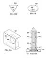
- FIG. 1Bdepicts a side view of a cross section of the wide metal inductor coil 114 .
- a characterization of the magnetic field 119 (dashed lines) produced by the wide metal inductor coil 114 during magnetizationillustrates that the wide metal inductor coil 114 produces a strong magnetic field 119 in the holes 118 a and 118 b , where the magnetizing field 119 is provided perpendicular (see dashed arrow) to the magnetizable material 130 being magnetized such that a North up or South up polarity magnetic source is printed into the magnetizing material 130 .
- the magnetic dipole(magnetic source, maxel) has either a North or South polarity on the surface of the magnetizing material 130 and an opposite pole beneath the surface of the magnetizing material 130 .
- Various improved wide metal inductor coilsare described in U.S. Non-provisional patent application Ser. No. 12/895,589, filed Sep. 30, 2010, titled “System and Method for Energy Generation”, and U.S. patent Non-provisional application Ser. No. 13/240,355, filed Sep. 22, 2011, titled “Magnetic Structure Production”, the contents of which are incorporated herein by reference.
- FIGS. 2A-2Ethere are illustrated different aspects of an exemplary magnetic print head 141 (similar to wide metal inductor coil 114 ) for a maxel-printing magnetic printer. It should be understood that more or fewer parts than those described and/or illustrated may alternatively comprise the magnetic print head 141 . Similarly, parts may be modified and/or combined in alternative manners that differ from those that are described and/or illustrated.
- FIG. 2Bdepicts an example outer layer 132 of the magnetic print head 141 .
- the outer layer 132may comprise a thin metal (e.g., 0.01′′ thick copper) having a generally round or circular shape (e.g., with a 16 mm diameter) and having substantially one-fourth of the circular shape removed or otherwise not present.
- the outer layer 132may include a tab 134 for receiving an electrical connection.
- the outer layer 132may define or include at least part of a hole portion 135 a that, when combined with one or more other layers 136 which has at least part of a hole portion 135 b , results in a hole 121 (e.g., with a 1 mm diameter) being formed in an approximate center of the magnetic print head 141 .
- the outer layer 132may be formed at least partially from a substantially flat plate.
- An arrowis illustrated on the outer layer 132 to indicate that a current received from the tab 134 may traverse around a three-quarter moon portion of the outer layer 132 .
- sizes, material types, shapes, etc. of component partsare provided by way of example but not limitation; other sizes, material types, shapes, etc. may alternatively be utilized and/or implemented.
- a diameter of one or more of the layers 132 and 136 of the magnetic print head 141which can also have a shape other than round (e.g., oval, rectangular, elliptical, triangular, hexagonal, etc.), may be selected to be large enough to handle a load of a current passing through the print head layers 132 and 136 and also large enough to substantially ensure no appreciable reverse magnetic field is produced near the hole 121 where the magnetic print head 141 produces a maxel (magnetic source) in the magnetizing material 130 .
- a shape other than rounde.g., oval, rectangular, elliptical, triangular, hexagonal, etc.
- the hole 121is also shown to comprise a substantially circular or round shape, this is by way of example only, and it should be appreciated that the hole 121 may alternatively comprise other shapes including but not limited to, oval, rectangular, elliptical, triangular, hexagonal, and so forth. Moreover, a size of the hole 121 may correspond to a desired maxel resolution in the magnetizing material 130 , whereby a given print head 141 may have a different sized hole 121 so as to print different sized maxels in the magnetizing material 130 .
- Example diameter sizes of holes 121 in print heads 141may include, but are not limited to, 0.7 mm to 4 mm. In addition, the diameter sizes of holes 121 may alternatively be smaller or larger, depending on design and/or particular application.
- FIG. 2Cdepicts an example inner layer 136 of the magnetic print head 141 .
- the inner layer 136may be similar to the outer layer 132 , except that it does not include a tab (e.g., see outer layer's tab 134 in FIG. 2B (PRIOR ART)).
- currentsee arrow
- FIG. 2Ddepicts an example non-conductive spacer 138 for the magnetic print head 141 .
- the spacer 138may be designed (e.g., in terms of size, shape, thickness, a combination thereof, etc.) to fill a portion of the outer layer 132 and/or the inner layer 136 such that the layers 132 and 136 have a conductive and a non-conductive portion.
- the outer and inner layers 132 and 136may still provide complete circular structures such that if they are stacked, they have no air regions other than the central hole 121 .
- the central hole 121may also be filled with a magnetizable material.
- the spacer 138may alternatively by shaped differently. If the spacer 138 is included in the design of the print head 141 , then the assembled print head 141 would be more rigid and therefore more robust and/or stable to thereby increase its lifecycle.
- FIG. 2Edepicts an example weld joint 140 between the outer layer 132 and the inner layer 136 with two spacers 138 a and 138 b .
- the outer and inner layers 132 and 136may have portions 139 a and 139 b that overlap to form the weld joint 140 .
- the weld joint 140may comprise an area that is used for attaching two layers 132 and 136 via some attachment mechanism including, but not limited to, welding (e.g., heliarc welding), soldering, adhesive, any combination thereof, and so forth.
- an insulating materiale.g., Kapton
- KaptonKapton
- the insulating materialmay be cut away or otherwise removed from the weld joint 140 , which enables the two conductor portions to be electrically attached thereby producing one and one-half turns of an inductor coil.
- an insulating materialmay be placed against a given layer 132 or 136 such that it insulates the given layer 132 or 136 from an adjoining layer except for a portion corresponding to the weld joint 140 between the two adjoining layers 132 and 136 .
- an insulating materialmay prevent current from passing between the layers 132 and 136 except at the weld joint 140 thereby resulting in each adjoining layer acting as three-quarters of a turn of an inductor coil (e.g., of the print head 141 ) if using example layer designs as illustrated in FIGS. 2B-2C (PRIOR ART).
- the present inventionprovides a system for magnetizing magnetic sources into a magnetizable material.
- the systemcomprises: (a) an inductor coil which has multiple layers forming a coil and a hole extending through the multiple layers; (b) a positioning device configured to position the inductor coil next to the magnetizable material; and (c) an electrical power source configured to provide electricity to the inductor coil such that the inductor coil emits a magnetic field that magnetizes an area on a surface of the magnetizable material, wherein the area on the surface of the magnetizable material is magnetized in a direction other than perpendicular to the magnetizable material such that there is a magnetic dipole with both a north polarity and a south polarity formed on the surface of the magnetizable material.
- the systemmay comprise multiple inductor coils which can magnetize multiple magnetic dipoles each with a north polarity and a south polarity on the surface of the magnetizable material.
- the present inventionprovides a method for magnetizing magnetic sources into a magnetizable material.
- the methodcomprises steps of: (a) providing an inductor coil having multiple layers forming a coil and a hole extending through the multiple layers; (b) positioning the inductor coil next to the magnetizable material; and (c) emitting from the inductor coil a magnetic field that magnetizes an area on a surface of the magnetizable material, wherein the area on the surface of the magnetizable material is magnetized in a direction other than perpendicular to the magnetizable material such that there is a magnetic dipole with both a north polarity and a south polarity formed on the surface of the magnetizable material.
- the methodmay utilize multiple inductor coils to magnetize multiple magnetic dipoles each with a north polarity and a south polarity on the surface of the magnetizable material.
- FIGS. 1A-1Billustrate a wide metal inductive coil which is positioned next to a magnetizing material such that when the wide metal inductive coil produces a magnetic field it is provided perpendicular to the magnetizable material being magnetized such that a North up or South up polarity magnetic source is printed in the the magnetizing material;
- FIGS. 2A-2Eillustrate different aspects of an exemplary magnetic print head (similar to the wide metal inductive coil of FIGS. 1A-1B ) for a maxel-printing magnetic printer;
- FIGS. 3A-3Dare several drawings of a wide metal inductor coil that is positioned relative to a magnetizable material so as to produce a magnetic field that magnetizes the magnetizable material in a direction parallel to the magnetizable material rather than perpendicular to the magnetizable material in accordance with an embodiment of the present invention
- FIGS. 4A-4Cshow different layers which are attached via butt welds to form the wide metal inductor coil shown in FIGS. 3A-3D in accordance with an embodiment of the present invention
- FIGS. 5A-5Iare several drawings of exemplary wide metal inductor coils which have all sorts of shapes and sizes themselves and holes with all sorts of shapes and sizes in accordance with different embodiments of the present invention
- FIGS. 6A-6Gare various diagrams illustrating how the wide metal inductor coils shown in FIGS. 2-5 or any wide metal inductor coil for that matter can be protected by placing it in a casting compound in accordance with an embodiment of the present invention
- FIGS. 7A-7Dare several drawings of exemplary magnetic structures (maxels) that can be formed on the magnetizable material in accordance with different embodiments of the the present invention.
- FIGS. 8A-8Lare various side-view diagrams which illustrate how a print head (wide metal inductor coil) can be tilted relative to the surface of the magnetizable material such that the magnetic field on the print head's outer perimeter magnetizes (prints) a magnetic source (maxel) on the magnetizable material in a direction other than perpendicular and other than parallel to the magnetizable material in accordance with different embodiments of the present invention; and
- FIGS. 9A-9Fare several diagrams illustrating a print head (wide metal inductor coil) which has angled hole formed therein in accordance with an embodiment of the present invention.
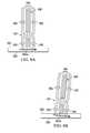
- FIGS. 3A-3Dthere are several drawings of a wide metal inductor coil 300 that is positioned relative to a magnetizable material 330 so as to produce a magnetic field 302 (dashed lines) that magnetizes in a direction parallel (dashed arrow) to the magnetizable material 330 rather than perpendicular to the magnetizable material 330 .
- the wide metal inductor coil 300is positioned relative to the magnetizable material 330 such that the magnetic field 302 produced at the outer perimeter 304 rather than the magnetic field 302 produced at the hole 301 of the wide metal inductor coil 300 is used magnetize the magnetizable material 330 .
- the wide metal inductor coil 300is positioned such that the direction of magnetization (dashed arrow) is parallel to a surface 332 of the magnetizable material 330 which means there is a north polarity and a south polarity formed on the surface 332 of the magnetizable material 330 (see FIG. 3 D's side view).
- the wide metal inductor coil 300has a configuration such that the width X of the hole 301 and the height Y of the wide metal inductor coil 300 , which is a function of thickness of each layer and the number of turns, determine the area on the surface 332 of a magnetizable material 330 that is subjected to the magnetic field 302 (see FIG. 3 A's side view and FIG.
- metal inductor coils 114 , 141 , 300 etc. . . .that can be positioned relative to the magnetizable material 330 (or vice versa) so as to form (print) a north polarity and a south polarity on the surface 332 of the magnetizable material 330 in accordance with the present invention.
- Some exemplary wide metal inductor coils 300 , 500 a , 500 b . . . 500 n in accordance with different embodiments of the present inventionare described in detail next with respect to FIGS. 4A-4C and 5 A- 5 I.
- FIGS. 4A-4Cthere are shown different layers 402 , 404 , and 406 which are attached via butt welds (where the different layers are butt-up against each other and welded together, using a laser welder) to form the aforementioned wide metal inductor coil 300 .
- FIGS. 4A-4Brespectively depict an outer layer 402 having a tab 403 and an inner layer 404 .
- Each of the two layers 402 and 404have an edge 408 that can be butted against another and welded to form a butt weld edge 409 .
- each of the two layers 402 and 404define or include at least part of a hole portion 407 a and 407 b such that their being combined results in the formation of the hole 301 (e.g., with a 1 mm diameter) in an approximate center of the wide metal inductor coil 300 (magnetic print head 300 )(see FIGS. 3A-3D ).
- the two layers 402 and 404are similar to layers 132 and 136 in the magnetic print head 141 of FIGS. 2A-2E (PRIOR ART) except the two layers 402 and 404 do not include the overlap portions 139 a and 139 b in layers 132 and 136 which are used to provide the weld joint 140 .
- FIG. 4Cdepicts the middle layer 406 which is a full circle with a slit that provides two edges 408 , where a left edge of one layer can butt against the right edge of a layer above or beneath the layer (or vice versa). Plus, the middle layer 406 has a hole 301 formed therein.
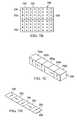
- FIGS. 5A-5Ithere are shown side-views of exemplary wide metal inductor coils 500 a , 500 b , 500 c , 500 d , 500 e , 500 f , 500 g , 500 h , and 500 i which have all sorts of sizes and shapes in accordance with different embodiments of the present invention.
- the wide metal inductor coils 500 a , 500 b , 500 c , 500 d , 500 e , 500 f , 500 g , 500 h , and 500 ihave different shapes and sizes of holes 502 a , 502 b , 502 c , 502 d , 502 e , 502 f , 502 g , 502 h , and 502 i .
- holes 502 a , 502 b , 502 c , 502 d , 502 e , 502 f , 502 g , 502 h , and 502 imay be just non-welded portions of abutted edges 508 which when welded to one another form weld 509 .
- the size of the resulting hole 502 dcan be as small as the cut in the metal layer that produces the two butt edges 508 (see FIG. 5D ).
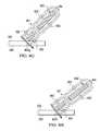
- FIGS. 6A-6Gthere are shown various diagrams illustrating how the aforementioned wide metal inductor coils 114 , 141 , 300 (shown), 500 a , 500 b , 500 c , 500 d , 500 e , 500 f , 500 g , 500 h , and 500 i or any wide metal inductor coil for that matter can be protected by placing it in a casting compound 602 (e.g., acrylic casting compound 602 ) in accordance with an embodiment of the present invention.
- the casting compound 602will harden and prevent damage to wide metal inductor coil 300 , which is typically made up of thin relatively soft metal layers of copper.
- FIGS. 6B-6Dshows a side-view of the wide metal inductor coil 300 (for example) encapsulated with the casting compound 602 and placed next to the magnetizable material 330 so as to produce the magnetic field 302 that magnetizes the surface 332 of the magnetizable material 330 in a direction that is parallel (see dashed arrow) rather than perpendicular which means there is a north polarity and a south polarity formed on the surface 332 of the magnetizable material 330 .
- the wide metal inductor coil 300(for example) is shown which is not only encapsulated with the casting compound 602 but also has a protective layer 604 attached thereto.
- the protective layer 604could be a thin metal layer such as a 0.003′′ thick layer of titanium or chrome.
- the protective layer 604can be used in addition to the casting compound 602 (as shown) or as an alternative to the casting compound 602 depending on the application.
- the protective layer 604can be placed at the bottom of an individual inductor coil such as the wide metal inductor coil 141 without using the casting compound 602 (see FIG. 6E ).
- the protective layer 604can be between multiple inductor coils 141 and the magnetizable material 330 (see FIG. 6F ).
- the protective layer 604can be between inductor coils 141 and 300 and the magnetizable material 330 (see FIG.
- an insulating layere.g., insulating layer 124 b
- an inductor coilsuch as inductor coil 300
- the protective layer 604as necessary to prevent current from conducting between the inductor coil 300 (for example) and the protective layer 604 .
- casting compounds 602 and/or protective layers 604can be used to enable the print head (e.g., wide metal inductor coil 114 , 141 , 300 (shown), 500 a , 500 b , 500 c , 500 d , 500 e , 500 f , 500 g , 500 h , and 500 i ) to be moved across the magnetizable material 330 from one maxel location to another without lifting the print head or magnetizable material 330 (or vice versa) so as to avoid damage to the print head during such movement.
- the print heade.g., wide metal inductor coil 114 , 141 , 300 (shown), 500 a , 500 b , 500 c , 500 d , 500 e , 500 f , 500 g , 500 h , and 500 i
- FIGS. 7A-7Dthere are illustrated several drawings of exemplary magnetic structures 700 (maxels 700 ) that can be formed on the magnetizable material 330 in accordance with the present invention.
- FIG. 7Adepicts multiple magnetic sources 700 (19 shown) printed parallel to the surface 332 of the magnetizable material 330 in somewhat of a random pattern, where each magnetic source 700 has a south polarity portion and a north polarity portion.
- the print heade.g., wide metal inductor coil 300
- the magnetizable material 330can be rotated to establish the print direction of each magnetic source 700 .
- FIG. 7Bdepicts rows and columns of printed magnetic sources 700 that resemble a checkerboard pattern on the surface 332 of the magnetizable material 330 .
- FIG. 7Cdepicts magnetic sources 700 a and 700 b in a Halbach array pattern printed into an axially sintered magnetizable material 330 where a “vertical” print head 141 (for example) can be used to produce the South Up or North up polarity magnetic sources 700 a and a “horizontal” print head 300 (for example) can be used to produce the South-North and North South magnetic sources 700 b .
- FIG. 1depicts rows and columns of printed magnetic sources 700 that resemble a checkerboard pattern on the surface 332 of the magnetizable material 330 .
- FIG. 7Cdepicts magnetic sources 700 a and 700 b in a Halbach array pattern printed into an axially sintered magnetizable material 330 where a “vertical” print head 141 (for example) can be used to produce the South Up or North up polarity magnetic
- FIG. 7Ddepicts a Halbach array pattern of magnetic sources 700 printed into a diametrically sintered magnetizable material 330 using a “horizontal” print head 300 (for example) where the direction of printing is a function of rotating the magnetizable material 330 or the “horizontal” print head 300 .
- the field strength used to print magnetic sources 700 which are printed “with the grain”can be less than the field strength used to print magnetic sources 700 “against the grain” so as to compensate for magnetization limitations.
- FIGS. 8A-8Jthere are various side-view diagrams which illustrate how a print head 300 (for example) can be tilted relative to the surface 332 of the magnetizable material 330 such that the magnetic field 302 on the print head's outer perimeter 304 magnetizes (prints) a magnetic source (maxel) on the magnetizable material 330 in a direction (see arrows) other than perpendicular and other than parallel to the magnetizable material 330 .
- FIGS. 8A-8Lshow several exemplary tilted print head 300 (tilted wide metal inductor coil 300 ) configurations to illustrate how different magnetization directions 802 a , 802 b , 802 c , 802 d , 802 e , 802 f , 820 g , 802 h , 802 i , and 802 l (dashed arrows) can be produced in the magnetizable material 330 .
- FIGS. 9A-9Fthere are several diagrams illustrating a print head 300 ′ (wide metal inductor coil 300 ′) which has angled hole 302 ′ formed therein in accordance with an embodiment of the present invention.
- the print head 300 ′has a hole 302 ′ that is slanted through the coil such that it can magnetize the magnetizable material 330 in a direction other than perpendicular or parallel to the surface 332 of the material 330 .
- the wide metal inductor coil 300 ′is made from multiple layers 902 a , 902 b , 902 c , 902 d and 902 e each having holes 302 a ′, 302 b ′, 302 c ′, 302 d ′ and 302 e ′ at five different positions (from left to right) such that when the layers 902 a , 902 b , 902 c , 902 d and 902 e are assembled they collectively form the angled hole 302 ′ in the wide metal inductor coil 300 ′.
- FIG. 9A-9Erespectively show top views of layers 902 a , 902 b , 902 c , 902 d and 902 e with their respective holes 302 a ′, 302 b ′, 302 c ′, 302 d ′ and 302 e ′ which are offset from one another such that when they are assembled they form the wide metal inductor coil 300 ′ with the angled hole 302 ′.
- FIG. 9Fis a side view of the wide metal inductor coil 300 ′ positioned next to the magnetizing material 330 so as to magnetize the magnetizable material 330 in a direction (see arrow) other than perpendicular or parallel to the surface 332 of the material 330 .
- the present inventionincludes a system and a method for magnetizing magnetic sources into a magnetizable material.
- the systemcould include an inductor coil 300 (for example)(actually multiple inductor coils could be used), a positioning device 350 , and an electrical power source 352 (see FIG. 3D ).
- the inductor coil 300which has multiple layers 402 , 404 and 406 forming a coil and a hole 301 extending through the multiple layers 402 , 404 and 406 .
- the positioning device 350is configured to position the inductor coil 300 next to the magnetizable material 330 (or vice-versa).
- the electrical power source 352is configured to provide electricity to the inductor coil 300 such that the inductor coil 300 emits a magnetic field 302 that magnetizes an area on a surface 332 of the magnetizable material 330 , wherein the area on the surface 332 of the magnetizable material 330 is magnetized in a direction other than perpendicular to the magnetizable material 330 such that a magnetic dipole with both a north polarity and a south polarity is formed on the surface 332 of the magnetizable material 330 .
Landscapes
- Physics & Mathematics (AREA)
- Electromagnetism (AREA)
- Engineering & Computer Science (AREA)
- Power Engineering (AREA)
- Coils Or Transformers For Communication (AREA)
Abstract
Description
This application claims the benefit U.S. Provisional Application Ser. No. 61/742,260 filed on Aug. 6, 2012. The contents of this document are incorporated by reference herein.
The present invention relates generally to a system and method for magnetization. More particularly, the present invention relates to a system and method for magnetizing magnetic sources into a magnetizable material.
A wide metal inductor coil for magnetizing magnetic sources known as maxels into a magnetizable material is described in U.S. Pat. No. 8,179,219, issued May 15, 2012, the contents of which are incorporated by reference herein. This known wide metalinductive coil 114 is shown inFIGS. 1A-1B (PRIOR ART). The wide metalinductive coil 114 includes a firstcircular conductor 116ahaving a desired thickness and ahole 118athrough it and aslotted opening 120aextending from thehole 118aand across the firstcircular conductor 116ato produce a discontinuity in the firstcircular conductor 116a. The wide metalinductive coil 114 further includes a secondcircular conductor 116bhaving ahole 118band aslotted opening 120bextending from thehole 118band across thecircular conductor 116bto produce a discontinuity in the secondcircular conductor 116b. The first and secondcircular conductors solder joint 122 that is beneath the firstcircular conductor 116aand on top of the secondcircular conductor 116b. Other attachment techniques other than soldering can also be used. Prior to the first and secondcircular conductors insulation layers circular conductors insulation layer 124ais placed beneath the firstcircular conductor 116aso it does not cover thesolder region 122 but otherwise insulates the remaining portion of the bottom of the firstcircular conductor 116afrom the secondcircular conductor 116b. When the first and secondcircular conductors insulation layer 124abetween them prevents current from conducting between them except at thesolder joint 122. Thesecond insulation layer 116bbeneath the secondcircular conductor 116bprevents current from conducting to the magnetizable material130 (seeFIG. 1B (PRIOR ART)). So, if themagnetizable material 130 is non-metallic, for example, a ceramic material, then thesecond insulation layer 116bis not needed. Moreover, if themagnetizable material 130 has generally insignificant conductive properties then thesecond insulation layer 116bis optional.
Afirst wire conductor 126 is soldered to the top of the firstcircular conductor 116aat a location next to theslotted opening 120abut opposite thesolder joint 122. The secondcircular conductor 116bhas a grove (or notch)127 in the bottom of it which can receive asecond wire conductor 128 that is then soldered to the secondcircular conductor 116bsuch that the bottom of the secondcircular conductor 116bremains substantially flat. Other methods can also be employed to connect thesecond wire conductor 128 to the secondcircular conductor 116bincluding placing thesecond wire conductor 128 into a hole drilled through a side of the secondcircular conductor 116band then soldering the second wire conductor116 to the secondcircular conductor 116b. As depicted inFIG. 1A (PRIOR ART), thesecond wire conductor 128 is fed through theholes circular conductors wire conductors circular conductors insulation layer 124ain between the twocircular conductors first conductor 126 can enter the firstcircular conductor 116a, travel clockwise around the firstcircular conductor 116a, travel through thesolder joint 122 to the secondcircular conductor 116b, travel clockwise around the secondcircular conductor 116band then out thesecond wire conductor 128, or current can travel the opposite path. Hence, depending on the connectivity of the first andsecond wire conductors FIG. 1B ).
Referring toFIGS. 2A-2E (PRIOR ART), there are illustrated different aspects of an exemplary magnetic print head141 (similar to wide metal inductor coil114) for a maxel-printing magnetic printer. It should be understood that more or fewer parts than those described and/or illustrated may alternatively comprise themagnetic print head 141. Similarly, parts may be modified and/or combined in alternative manners that differ from those that are described and/or illustrated. For certain example embodiments,FIG. 2B (PRIOR ART) depicts an exampleouter layer 132 of themagnetic print head 141. Theouter layer 132 may comprise a thin metal (e.g., 0.01″ thick copper) having a generally round or circular shape (e.g., with a 16 mm diameter) and having substantially one-fourth of the circular shape removed or otherwise not present. Theouter layer 132 may include atab 134 for receiving an electrical connection. Theouter layer 132 may define or include at least part of ahole portion 135athat, when combined with one or moreother layers 136 which has at least part of ahole portion 135b, results in a hole121 (e.g., with a 1 mm diameter) being formed in an approximate center of themagnetic print head 141. As shown for an example implementation, theouter layer 132 may be formed at least partially from a substantially flat plate. An arrow is illustrated on theouter layer 132 to indicate that a current received from thetab 134 may traverse around a three-quarter moon portion of theouter layer 132. It should be noted that sizes, material types, shapes, etc. of component parts are provided by way of example but not limitation; other sizes, material types, shapes, etc. may alternatively be utilized and/or implemented.
For example implementations, a diameter of one or more of thelayers magnetic print head 141, which can also have a shape other than round (e.g., oval, rectangular, elliptical, triangular, hexagonal, etc.), may be selected to be large enough to handle a load of a current passing through theprint head layers hole 121 where themagnetic print head 141 produces a maxel (magnetic source) in themagnetizing material 130. Although thehole 121 is also shown to comprise a substantially circular or round shape, this is by way of example only, and it should be appreciated that thehole 121 may alternatively comprise other shapes including but not limited to, oval, rectangular, elliptical, triangular, hexagonal, and so forth. Moreover, a size of thehole 121 may correspond to a desired maxel resolution in themagnetizing material 130, whereby a givenprint head 141 may have a different sizedhole 121 so as to print different sized maxels in themagnetizing material 130. Example diameter sizes ofholes 121 inprint heads 141 may include, but are not limited to, 0.7 mm to 4 mm. In addition, the diameter sizes ofholes 121 may alternatively be smaller or larger, depending on design and/or particular application.
For an example assembly procedure, prior to attaching the twolayers layer layer layers layers FIGS. 2B-2C (PRIOR ART).
Although the aforementioned wide metalinductive coil 114 and themagnetic print head 141 work well it is still desirable to improve upon these components or at least how these components can be used in a different manner to form magnetizing magnetic sources (maxels) into a magnetizable material. Such improvements are the subject of the present invention.
A system and method for magnetizing magnetic sources into a magnetizable material are described in the independent claims of the present application. Advantageous embodiments of the system and method have been described in the dependent claims of the present application.
In one aspect, the present invention provides a system for magnetizing magnetic sources into a magnetizable material. In one embodiment, the system comprises: (a) an inductor coil which has multiple layers forming a coil and a hole extending through the multiple layers; (b) a positioning device configured to position the inductor coil next to the magnetizable material; and (c) an electrical power source configured to provide electricity to the inductor coil such that the inductor coil emits a magnetic field that magnetizes an area on a surface of the magnetizable material, wherein the area on the surface of the magnetizable material is magnetized in a direction other than perpendicular to the magnetizable material such that there is a magnetic dipole with both a north polarity and a south polarity formed on the surface of the magnetizable material. In addition, the system may comprise multiple inductor coils which can magnetize multiple magnetic dipoles each with a north polarity and a south polarity on the surface of the magnetizable material.
In another aspect, the present invention provides a method for magnetizing magnetic sources into a magnetizable material. The method comprises steps of: (a) providing an inductor coil having multiple layers forming a coil and a hole extending through the multiple layers; (b) positioning the inductor coil next to the magnetizable material; and (c) emitting from the inductor coil a magnetic field that magnetizes an area on a surface of the magnetizable material, wherein the area on the surface of the magnetizable material is magnetized in a direction other than perpendicular to the magnetizable material such that there is a magnetic dipole with both a north polarity and a south polarity formed on the surface of the magnetizable material. In addition, the method may utilize multiple inductor coils to magnetize multiple magnetic dipoles each with a north polarity and a south polarity on the surface of the magnetizable material.
Additional aspects of the invention will be set forth, in part, in the detailed description, figures and any claims which follow, and in part will be derived from the detailed description, or can be learned by practice of the invention. It is to be understood that both the foregoing general description and the following detailed description are exemplary and explanatory only and are not restrictive of the invention as disclosed.
A more complete understanding of the present invention may be obtained by reference to the following detailed description when taken in conjunction with the accompanying drawings wherein:
Referring toFIGS. 3A-3D , there are several drawings of a widemetal inductor coil 300 that is positioned relative to amagnetizable material 330 so as to produce a magnetic field302 (dashed lines) that magnetizes in a direction parallel (dashed arrow) to themagnetizable material 330 rather than perpendicular to themagnetizable material 330. As discussed above, the widemetal inductor coil FIGS. 1-2 (PRIOR ART) are positioned so as to use the magnetic field near theirhole 118 and121 to magnetize themagnetizable material 130 in a direction that is perpendicular to themagnetizable material 130 which means there is a north up or south up polarity magnetic source printed into the surface of the magnetizingmaterial 130. In contrast, the widemetal inductor coil 300 is positioned relative to themagnetizable material 330 such that themagnetic field 302 produced at theouter perimeter 304 rather than themagnetic field 302 produced at thehole 301 of the widemetal inductor coil 300 is used magnetize themagnetizable material 330. In the illustrated example, the widemetal inductor coil 300 is positioned such that the direction of magnetization (dashed arrow) is parallel to asurface 332 of themagnetizable material 330 which means there is a north polarity and a south polarity formed on thesurface 332 of the magnetizable material330 (see FIG.3D's side view). The widemetal inductor coil 300 has a configuration such that the width X of thehole 301 and the height Y of the widemetal inductor coil 300, which is a function of thickness of each layer and the number of turns, determine the area on thesurface 332 of amagnetizable material 330 that is subjected to the magnetic field302 (see FIG.3A's side view and FIG.3C's top view). One skilled in the art with the teachings herein will readily appreciate that there is a wide variety of metal inductor coils114,141,300 etc. . . . that can be positioned relative to the magnetizable material330 (or vice versa) so as to form (print) a north polarity and a south polarity on thesurface 332 of themagnetizable material 330 in accordance with the present invention. Some exemplary wide metal inductor coils300,500a,500b. . .500nin accordance with different embodiments of the present invention are described in detail next with respect toFIGS. 4A-4C and5A-5I.
Referring toFIGS. 4A-4C , there are showndifferent layers metal inductor coil 300.FIGS. 4A-4B respectively depict anouter layer 402 having atab 403 and aninner layer 404. Each of the twolayers edge 408 that can be butted against another and welded to form abutt weld edge 409. Further, each of the twolayers hole portion FIGS. 3A-3D ). Further, the twolayers layers magnetic print head 141 ofFIGS. 2A-2E (PRIOR ART) except the twolayers overlap portions layers FIG. 4C depicts themiddle layer 406 which is a full circle with a slit that provides twoedges 408, where a left edge of one layer can butt against the right edge of a layer above or beneath the layer (or vice versa). Plus, themiddle layer 406 has ahole 301 formed therein.
Referring toFIGS. 5A-5I , there are shown side-views of exemplary wide metal inductor coils500a,500b,500c,500d,500e,500f,500g,500h, and500iwhich have all sorts of sizes and shapes in accordance with different embodiments of the present invention. Further, the wide metal inductor coils500a,500b,500c,500d,500e,500f,500g,500h, and500ihave different shapes and sizes ofholes holes edges 508 which when welded to one anotherform weld 509. For instance, the size of the resultinghole 502dcan be as small as the cut in the metal layer that produces the two butt edges508 (seeFIG. 5D ). One skilled in the art with these teachings will recognize that all sorts of print head designs based on wide metal inductor coils500a,500b,500c,500d,500e,500f,500g,500h, and500iare possible which can be used/positioned to produce a magnetic field that magnetizes thesurface 332 of themagnetizable material 330 in a direction that is parallel rather than perpendicular with respect to themagnetizable material 330 which means there is a north polarity and a south polarity formed on thesurface 332 of themagnetizable material 330.
Referring toFIGS. 6A-6G , there are shown various diagrams illustrating how the aforementioned wide metal inductor coils114,141,300 (shown),500a,500b,500c,500d,500e,500f,500g,500h, and500ior any wide metal inductor coil for that matter can be protected by placing it in a casting compound602 (e.g., acrylic casting compound602) in accordance with an embodiment of the present invention. The castingcompound 602 will harden and prevent damage to widemetal inductor coil 300, which is typically made up of thin relatively soft metal layers of copper.FIG. 6B shows a side-view of the wide metal inductor coil300 (for example) encapsulated with the castingcompound 602 and placed next to themagnetizable material 330 so as to produce themagnetic field 302 that magnetizes thesurface 332 of themagnetizable material 330 in a direction that is parallel (see dashed arrow) rather than perpendicular which means there is a north polarity and a south polarity formed on thesurface 332 of themagnetizable material 330. InFIGS. 6C-6D , the wide metal inductor coil300 (for example) is shown which is not only encapsulated with the castingcompound 602 but also has aprotective layer 604 attached thereto. Theprotective layer 604 could be a thin metal layer such as a 0.003″ thick layer of titanium or chrome. Theprotective layer 604 can be used in addition to the casting compound602 (as shown) or as an alternative to the castingcompound 602 depending on the application. For example, theprotective layer 604 can be placed at the bottom of an individual inductor coil such as the widemetal inductor coil 141 without using the casting compound602 (seeFIG. 6E ). Alternatively, theprotective layer 604 can be betweenmultiple inductor coils 141 and the magnetizable material330 (seeFIG. 6F ). Or, theprotective layer 604 can be betweeninductor coils FIG. 6G ) where in this example the twoinductor coils compound 602. If desired, an insulating layer (e.g., insulatinglayer 124b) can be placed between an inductor coil, such asinductor coil 300, and theprotective layer 604 as necessary to prevent current from conducting between the inductor coil300 (for example) and theprotective layer 604. Generally, one skilled in the art will recognize with the teachings herein that castingcompounds 602 and/orprotective layers 604 can be used to enable the print head (e.g., widemetal inductor coil magnetizable material 330 from one maxel location to another without lifting the print head or magnetizable material330 (or vice versa) so as to avoid damage to the print head during such movement.
Referring toFIGS. 7A-7D , there are illustrated several drawings of exemplary magnetic structures700 (maxels700) that can be formed on themagnetizable material 330 in accordance with the present invention.FIG. 7A depicts multiple magnetic sources700 (19 shown) printed parallel to thesurface 332 of themagnetizable material 330 in somewhat of a random pattern, where eachmagnetic source 700 has a south polarity portion and a north polarity portion. It should be appreciated that the print head (e.g., wide metal inductor coil300) and or themagnetizable material 330 can be rotated to establish the print direction of eachmagnetic source 700.FIG. 7B depicts rows and columns of printedmagnetic sources 700 that resemble a checkerboard pattern on thesurface 332 of themagnetizable material 330.FIG. 7C depictsmagnetic sources magnetizable material 330 where a “vertical” print head141 (for example) can be used to produce the South Up or North up polaritymagnetic sources 700aand a “horizontal” print head300 (for example) can be used to produce the South-North and North Southmagnetic sources 700b.FIG. 7D depicts a Halbach array pattern ofmagnetic sources 700 printed into a diametrically sinteredmagnetizable material 330 using a “horizontal” print head300 (for example) where the direction of printing is a function of rotating themagnetizable material 330 or the “horizontal”print head 300. It should be noted that due to the magnetization direction on themagnetizable material 330, the field strength used to printmagnetic sources 700 which are printed “with the grain” can be less than the field strength used to printmagnetic sources 700 “against the grain” so as to compensate for magnetization limitations.
Referring toFIGS. 8A-8J , there are various side-view diagrams which illustrate how a print head300 (for example) can be tilted relative to thesurface 332 of themagnetizable material 330 such that themagnetic field 302 on the print head'souter perimeter 304 magnetizes (prints) a magnetic source (maxel) on themagnetizable material 330 in a direction (see arrows) other than perpendicular and other than parallel to themagnetizable material 330. In this example,FIGS. 8A-8L show several exemplary tilted print head300 (tilted wide metal inductor coil300) configurations to illustrate howdifferent magnetization directions magnetizable material 330.
Referring toFIGS. 9A-9F , there are several diagrams illustrating aprint head 300′ (widemetal inductor coil 300′) which has angledhole 302′ formed therein in accordance with an embodiment of the present invention. In particular, theprint head 300′ has ahole 302′ that is slanted through the coil such that it can magnetize themagnetizable material 330 in a direction other than perpendicular or parallel to thesurface 332 of thematerial 330. In this example, the widemetal inductor coil 300′ is made frommultiple layers holes 302a′,302b′,302c′,302d′ and302e′ at five different positions (from left to right) such that when thelayers angled hole 302′ in the widemetal inductor coil 300′.FIGS. 9A-9E respectively show top views oflayers respective holes 302a′,302b′,302c′,302d′ and302e′ which are offset from one another such that when they are assembled they form the widemetal inductor coil 300′ with theangled hole 302′.FIG. 9F is a side view of the widemetal inductor coil 300′ positioned next to the magnetizingmaterial 330 so as to magnetize themagnetizable material 330 in a direction (see arrow) other than perpendicular or parallel to thesurface 332 of thematerial 330.
In view of the foregoing, one skilled in the art will readily appreciate that the present invention includes a system and a method for magnetizing magnetic sources into a magnetizable material. For instance, the system could include an inductor coil300 (for example)(actually multiple inductor coils could be used), apositioning device 350, and an electrical power source352 (seeFIG. 3D ). Theinductor coil 300 which hasmultiple layers hole 301 extending through themultiple layers positioning device 350 is configured to position theinductor coil 300 next to the magnetizable material330 (or vice-versa). Theelectrical power source 352 is configured to provide electricity to theinductor coil 300 such that theinductor coil 300 emits amagnetic field 302 that magnetizes an area on asurface 332 of themagnetizable material 330, wherein the area on thesurface 332 of themagnetizable material 330 is magnetized in a direction other than perpendicular to themagnetizable material 330 such that a magnetic dipole with both a north polarity and a south polarity is formed on thesurface 332 of themagnetizable material 330.
Although multiple embodiments of the present invention have been illustrated in the accompanying Drawings and described in the foregoing Detailed Description, it should be understood that the present invention is not limited to the disclosed embodiments, but is capable of numerous rearrangements, modifications and substitutions without departing from the invention as set forth and defined by the following claims. It should also be noted that the reference to the “present invention” or “invention” used herein relates to exemplary embodiments and not necessarily to every embodiment that is encompassed by the appended claims.
Claims (20)
1. A system for magnetizing magnetic sources into a magnetizable material, the system comprising:
an inductor coil having multiple layers forming a coil and a hole extending through the multiple layers;
a positioning device configured to position an outer perimeter of the inductor coil next to a surface of the magnetizable material; and
an electrical power source configured to provide electricity to the inductor coil such that the inductor coil produces a magnetic field at the outer perimeter of the inductor coil that magnetizes an area on the surface of the magnetizable material, wherein the area on the surface of the magnetizable material is magnetized in a direction other than perpendicular to the surface of the magnetizable material such that there is a magnetic dipole with both a north polarity and a south polarity formed on the surface of the magnetizable material.
2. The system ofclaim 1 , wherein the positioning device is further configured to tilt the inductor coil with respect to the magnetizable material such that the inductor coil emits the magnetic field to magnetize the area of the surface of the magnetizable material in a direction other than perpendicular to the magnetizable material and other than parallel to the magnetizable material.
3. The system ofclaim 1 , further comprising a protective layer which is placed between the inductor coil and the magnetizable material.
4. The system ofclaim 1 , wherein the multiple layers are welded to one another to form the coil with a number of turns.
5. The system ofclaim 4 , wherein the weld is an overlap weld or a butt weld.
6. The system ofclaim 1 , wherein a height of the coil which is a function of a thickness of each layer and the number of turns along with a width of the hole determines the area on the surface of the magnetizable material that is magnetized by the inductor coil.
7. The system ofclaim 1 , wherein the inductor coil is placed in a casting compound.
8. The system ofclaim 1 , wherein the hole formed in the inductor coil is a slanted hole.
9. The system ofclaim 1 , wherein the hole formed in the inductor coil is either a rectangular-shaped hole, a circular-shaped hole, a triangular-shaped hole, or an oval-shaped hole.
10. The system ofclaim 1 , further comprising:
another inductor coil having multiple layers forming a coil and a hole extending through the multiple layers;
the positioning device is configured to also position the another inductor coil next to the surface of the magnetizable material; and
the electrical power source is also configured to provide electricity to the another inductor coil such that the another inductor coil produces a magnetic field at the outer perimeter of the coil that magnetizes another area on the surface of the magnetizable material, wherein the another area on the surface of the magnetizable material is magnetized in a perpendicular direction such that there is a magnetic dipole with either a north polarity or a south polarity formed on the surface of the magnetizable material.
11. A method for magnetizing magnetic sources into a magnetizable material, the method comprising:
providing an inductor coil having multiple layers forming a coil and a hole extending through the multiple layers;
positioning an outer perimeter of the inductor coil next to a surface of the magnetizable material; and
producing a magnetic field at the outer perimeter of the inductor coil that magnetizes an area on the surface of the magnetizable material, wherein the area on the surface of the magnetizable material is magnetized in a direction other than perpendicular to the surface of the magnetizable material such that there is a magnetic dipole with both a north polarity and a south polarity formed on the surface of the magnetizable material.
12. The method ofclaim 11 , wherein the positioning step further includes a step of tilting the inductor coil with respect to the magnetizable material such that the inductor coil emits the magnetic field to magnetize the area of the surface of the magnetizable material in a direction other than perpendicular to the magnetizable material and other than parallel to the magnetizable material.
13. The method ofclaim 11 , further comprising a step of placing a protective layer between the inductor coil and the magnetizable material.
14. The method ofclaim 11 , wherein the multiple layers are welded to one another to form the coil with a number of turns.
15. The method ofclaim 14 , wherein the weld is an overlap weld or a butt weld.
16. The method ofclaim 11 , wherein a height of the coil which is a function of a thickness of each layer and the number of turns along with a width of the hole determines the area on the surface of the magnetizable material that is magnetized by the inductor coil.
17. The method ofclaim 11 , wherein the inductor coil is placed in a casting compound.
18. The method ofclaim 11 , wherein the hole formed in the inductor coil is a slanted hole.
19. The method ofclaim 11 , wherein the hole formed in the inductor coil is either a rectangular-shaped hole, a circular-shaped hole, a triangular-shaped hole, or an oval-shaped hole.
20. The method ofclaim 11 , further comprising steps of:
providing another inductor coil having multiple layers forming a coil and a hole extending through the multiple layers;
positioning the another inductor coil next to the magnetizable material; and
producing a magnetic field at the outer perimeter of the another inductor coil that magnetizes another area on the surface of the magnetizable material, wherein the another area on the surface of the magnetizable material is magnetized in a perpendicular direction such that there is a magnetic dipole with either a north polarity or a south polarity formed on the surface of the magnetizable material.
Priority Applications (5)
| Application Number | Priority Date | Filing Date | Title |
|---|---|---|---|
| US13/959,201US9257219B2 (en) | 2012-08-06 | 2013-08-05 | System and method for magnetization |
| US14/198,400US20140211360A1 (en) | 2009-06-02 | 2014-03-05 | System and method for producing magnetic structures |
| US14/869,590US9365049B2 (en) | 2009-09-22 | 2015-09-29 | Magnetizing inductor and a method for producing a magnetizing inductor |
| US15/082,605US10204727B2 (en) | 2009-06-02 | 2016-03-28 | Systems and methods for producing magnetic structures |
| US15/247,689US20160365187A1 (en) | 2009-06-02 | 2016-08-25 | System and method for producing magnetic structures |
Applications Claiming Priority (2)
| Application Number | Priority Date | Filing Date | Title |
|---|---|---|---|
| US201261742260P | 2012-08-06 | 2012-08-06 | |
| US13/959,201US9257219B2 (en) | 2012-08-06 | 2013-08-05 | System and method for magnetization |
Related Parent Applications (1)
| Application Number | Title | Priority Date | Filing Date |
|---|---|---|---|
| US14/052,891Continuation-In-PartUS9275783B2 (en) | 2009-06-02 | 2013-10-14 | System and method for demagnetization of a magnetic structure region |
Related Child Applications (3)
| Application Number | Title | Priority Date | Filing Date |
|---|---|---|---|
| US13/659,444Continuation-In-PartUS20140111296A1 (en) | 2009-06-02 | 2012-10-24 | System and method for producing magnetic structures |
| US13/687,819Continuation-In-PartUS20130135071A1 (en) | 2009-06-02 | 2012-11-28 | System and method for focusing magnetic fields |
| US14/198,400Continuation-In-PartUS20140211360A1 (en) | 2009-06-02 | 2014-03-05 | System and method for producing magnetic structures |
Publications (2)
| Publication Number | Publication Date |
|---|---|
| US20140035707A1 US20140035707A1 (en) | 2014-02-06 |
| US9257219B2true US9257219B2 (en) | 2016-02-09 |
Family
ID=50024908
Family Applications (1)
| Application Number | Title | Priority Date | Filing Date |
|---|---|---|---|
| US13/959,201Expired - Fee RelatedUS9257219B2 (en) | 2009-06-02 | 2013-08-05 | System and method for magnetization |
Country Status (1)
| Country | Link |
|---|---|
| US (1) | US9257219B2 (en) |
Cited By (2)
| Publication number | Priority date | Publication date | Assignee | Title |
|---|---|---|---|---|
| US20170322481A1 (en)* | 2014-11-21 | 2017-11-09 | Tormaxx Gmbh | Holding element for a camera and camera arrangement, holding element and a helmet |
| WO2021168120A1 (en) | 2020-02-20 | 2021-08-26 | Magnetic Mechanisms L.L.C. | Detachable magnet device |
Families Citing this family (2)
| Publication number | Priority date | Publication date | Assignee | Title |
|---|---|---|---|---|
| US20150327638A1 (en)* | 2014-05-15 | 2015-11-19 | Debashis Ghosh | Apparatus, system, and method of providing linkage between two or more objects such that they can passively track or follow one another |
| CN105006334B (en)* | 2015-06-23 | 2017-08-18 | 歌尔股份有限公司 | Multipath magnetic circuit magnetizes technique |
Citations (444)
| Publication number | Priority date | Publication date | Assignee | Title |
|---|---|---|---|---|
| US93931A (en) | 1869-08-17 | A m o s w e s t c o t t | ||
| US342666A (en) | 1886-05-25 | Slakch kuuivl | ||
| US361248A (en) | 1887-04-12 | Holder for metal articles | ||
| US381968A (en) | 1887-10-12 | 1888-05-01 | Nikola Tesla | Electro-magnetic motor |
| US400809A (en) | 1889-04-02 | Alternatinq-current electric reciprocating engine | ||
| US405109A (en) | 1889-06-11 | Thill-coupling | ||
| US450543A (en) | 1891-04-14 | Electro-magnetic reciprocating engine | ||
| US493858A (en) | 1893-03-21 | Transmission of power | ||
| US675323A (en) | 1900-05-22 | 1901-05-28 | Eugene B Clark | Lifting-magnet. |
| US687292A (en) | 1900-09-06 | 1901-11-26 | David B Carse | Power-transmitting device. |
| US996933A (en) | 1905-12-16 | 1911-07-04 | Otis Elevator Co | Magnetic-traction-wheel-drive elevator. |
| US1024418A (en) | 1911-03-14 | 1912-04-23 | Emil Podlesak | Inductor-alternator. |
| US1081462A (en) | 1912-04-25 | 1913-12-16 | D & W Fuse Company | Magnetic chuck. |
| US1171351A (en) | 1913-03-22 | 1916-02-08 | Neuland Electrical Company Inc | Apparatus for transmitting power. |
| US1180489A (en) | 1915-05-22 | 1916-04-25 | Webster Electric Co Inc | Magneto-machine. |
| US1184056A (en) | 1915-07-31 | 1916-05-23 | Harry Randolph Van Deventer | Self-contained generating and lighting unit. |
| US1236234A (en) | 1917-03-30 | 1917-08-07 | Oscar R Troje | Toy building-block. |
| US1252289A (en) | 1917-10-04 | 1918-01-01 | Thomas E Murray Jr | Method of producing integral projections on metal plates. |
| US1290190A (en) | 1912-11-29 | 1919-01-07 | Matie C Messler | Generating mechanism. |
| US1301135A (en) | 1917-03-28 | 1919-04-22 | Kar Engineering Company | Fixture for use with magnetic chucks. |
| US1307342A (en) | 1919-06-24 | Igniter | ||
| US1312546A (en) | 1919-08-12 | Fixture for magnetic chucks | ||
| US1323546A (en) | 1919-12-02 | palosky and s | ||
| US1343751A (en) | 1919-03-19 | 1920-06-15 | Taftpeirce Mfg Company | Adjustable v-block and the like for magnetic chucks |
| US1544010A (en) | 1923-04-24 | 1925-06-30 | L Air Liquide Soc | Generator of electric current |
| US1554254A (en) | 1923-12-14 | 1925-09-22 | Zbinden Emile | Electromagnetic power device |
| US1554236A (en) | 1920-01-27 | 1925-09-22 | Taftpeirce Mfg Company | Waterproof magnetic chuck |
| US1624741A (en) | 1926-12-10 | 1927-04-12 | Louis A Leppke | Display device |
| US1784256A (en) | 1928-10-12 | 1930-12-09 | Harold E Stout | Method of manufacturing sinkers for knitting machines |
| US1785643A (en) | 1927-04-25 | 1930-12-16 | Noack Walter Gustav | Internal-combustion power plant |
| US1823326A (en) | 1926-06-16 | 1931-09-15 | Westinghouse Electric & Mfg Co | Vibration recorder |
| US1895129A (en) | 1931-03-30 | 1933-01-24 | Jones David | Magnetic work-holding device |
| US1975175A (en) | 1932-11-05 | 1934-10-02 | Heintz & Kaufman Ltd | Magneto field member |
| US2048161A (en) | 1934-03-29 | 1936-07-21 | Bosch Robert | Dynamo-electric machine frame |
| US2058339A (en) | 1935-09-12 | 1936-10-20 | Gen Electric | Dynamo-electric machine |
| FR823395A (en) | 1936-09-28 | 1938-01-19 | Hatot | Improvements in remote electrical control systems and devices, in particular synchronous motors and clocks |
| US2111643A (en) | 1935-12-31 | 1938-03-22 | Western Geophysical Company | Seismometer |
| US2130213A (en) | 1935-10-23 | 1938-09-13 | Texas Co | Vibration detector |
| US2147482A (en) | 1936-12-01 | 1939-02-14 | Gen Electric | Luminaire |
| US2158132A (en) | 1938-02-17 | 1939-05-16 | Bell Telephone Labor Inc | Magnet body and process of making the same |
| US2186074A (en) | 1939-05-13 | 1940-01-09 | Koller Steven | Magnetic work holder |
| US2240035A (en) | 1938-03-23 | 1941-04-29 | Catherall Alfred Cyril | Securing device |
| US2243555A (en) | 1940-08-21 | 1941-05-27 | Gen Electric | Magnet gearing |
| US2245268A (en) | 1940-11-12 | 1941-06-10 | Gen Electric | Dynamoelectric machine |
| US2269149A (en) | 1939-11-24 | 1942-01-06 | Gen Electric | Permanent magnet |
| US2286897A (en) | 1942-06-16 | Vibration pickup | ||
| US2296754A (en) | 1939-04-29 | 1942-09-22 | Texas Co | Astatic electromagnetic vibration detector |
| US2315045A (en) | 1939-10-09 | 1943-03-30 | Illinois Testing Laboratories | Metal detection device |
| US2316616A (en) | 1942-02-11 | 1943-04-13 | Gen Electric | Vibration responsive device |
| US2327748A (en) | 1941-04-24 | 1943-08-24 | O S Walker Co Inc | Universal work-holding plate for magnetic chucks |
| US2337248A (en) | 1941-07-21 | 1943-12-21 | Koller Steven | Gauging tool |
| US2337249A (en) | 1941-10-27 | 1943-12-21 | Koller Steven | Wheel dressing tool |
| US2362151A (en) | 1943-08-18 | 1944-11-07 | Ostenberg Pontus | Electric generator |
| US2389298A (en) | 1943-03-27 | 1945-11-20 | Ellis Robert | Apparel fastener |
| US2401887A (en) | 1943-08-30 | 1946-06-11 | Sheppard Frank | Magnetic chuck attachment plate |
| US2409857A (en) | 1944-04-15 | 1946-10-22 | Westinghouse Air Brake Co | Linear generator |
| US2414653A (en) | 1944-01-10 | 1947-01-21 | Alex E Lookholder | Magnetic holder for brushes and other articles |
| US2426322A (en) | 1943-06-30 | 1947-08-26 | Magnavox Co | Electric impulse generator |
| US2438231A (en) | 1946-01-18 | 1948-03-23 | Schultz | Closure for fountain pens and the like |
| US2471634A (en) | 1944-07-27 | 1949-05-31 | Winters & Crampton Corp | Refrigerator closure and seal |
| US2472127A (en) | 1946-02-15 | 1949-06-07 | Frank K Slason | Temperature compensated vibration pickup |
| US2475456A (en) | 1944-08-24 | 1949-07-05 | Walter J Norlander | Magnetic work holder |
| US2475200A (en) | 1945-06-28 | 1949-07-05 | Rca Corp | Signal recording apparatus |
| US2483895A (en) | 1947-04-19 | 1949-10-04 | Electronoid Corp | Electromagnetic straight-line motor |
| US2508305A (en) | 1948-02-05 | 1950-05-16 | Macy O Teetor | Magnetic door catch |
| US2513226A (en) | 1945-07-11 | 1950-06-27 | Redmond Company Inc | Field structure for rotating electrical equipement |
| US2514927A (en) | 1945-10-24 | 1950-07-11 | American Hardware Corp | Magnetic door holder |
| US2520828A (en) | 1947-12-27 | 1950-08-29 | Carter Motor Company | Motor-generator construction |
| US2540796A (en) | 1949-11-28 | 1951-02-06 | Austin N Stanton | Vibration translator |
| US2544077A (en) | 1948-07-24 | 1951-03-06 | Charles B Gardner | Projectile-actuated surge generator |
| US2565624A (en) | 1949-04-22 | 1951-08-28 | Russell E Phelon | Holder for articles of magnetic material |
| US2570625A (en) | 1947-11-21 | 1951-10-09 | Zimmerman Harry | Magnetic toy blocks |
| US2640955A (en) | 1949-04-02 | 1953-06-02 | Electronoid Corp | Electromagnetic straight-line motor |
| US2690349A (en) | 1951-03-26 | 1954-09-28 | Macy O Teetor | Magnetic door catch |
| US2694164A (en) | 1952-02-07 | 1954-11-09 | Walter A Geppelt | Magnetic wheel |
| US2694613A (en) | 1949-06-15 | 1954-11-16 | Williams David Franklin | Refrigerated display cabinet and lid structure |
| US2701158A (en) | 1954-05-06 | 1955-02-01 | Lab Equipment Corp | Magnetic door catch |
| US2722617A (en) | 1951-11-28 | 1955-11-01 | Hartford Nat Bank & Trust Comp | Magnetic circuits and devices |
| US2740946A (en) | 1952-12-16 | 1956-04-03 | Geophysique Cie Gle | Seismometer |
| US2770759A (en) | 1955-02-08 | 1956-11-13 | Amerock Corp | Magnetic assembly |
| US2787719A (en) | 1952-06-20 | 1957-04-02 | Albert G Thomas | Step motor and control system therefor |
| US2820411A (en) | 1948-10-07 | 1958-01-21 | Robert H Park | Inertia responsive magneto generator |
| US2825863A (en) | 1954-10-18 | 1958-03-04 | Krupen Philip | Energizer |
| US2837366A (en) | 1956-12-24 | 1958-06-03 | Loeb Morris | Magnetic catch |
| US2842688A (en) | 1953-10-30 | 1958-07-08 | Bendix Aviat Corp | Linear rate generator |
| US2853331A (en) | 1953-12-23 | 1958-09-23 | Macy O Teetor | Magnetic catch |
| US2888291A (en) | 1956-08-10 | 1959-05-26 | Engineered Products Company | Magnetic catch |
| US2896991A (en) | 1956-07-17 | 1959-07-28 | Magni Power Company | Magnetic door holder |
| US2900592A (en) | 1958-10-03 | 1959-08-18 | Baruch Sydney Norton | Power sources |
| US2932545A (en) | 1958-10-31 | 1960-04-12 | Gen Electric | Magnetic door latching arrangement for refrigerator |
| US2935352A (en) | 1954-06-25 | 1960-05-03 | Heppner Sales Co | Magnetic catch |
| US2935353A (en) | 1958-11-13 | 1960-05-03 | Loeb Morris | Magnetic catch |
| US2936437A (en) | 1956-09-20 | 1960-05-10 | United Carr Fastener Corp | Electrical apparatus |
| US2959747A (en) | 1957-10-11 | 1960-11-08 | Elgin Nat Watch Co | Electromotive vibrator and oscillator systems |
| US2962318A (en) | 1956-01-19 | 1960-11-29 | Macy O Teetor | Magnetic catch |
| US3024374A (en) | 1957-10-07 | 1962-03-06 | Bendix Corp | Linear rate generator |
| US3055999A (en) | 1961-05-02 | 1962-09-25 | Alfred R Lucas | Magnetic switch of the snap acting type |
| US3089986A (en) | 1960-03-28 | 1963-05-14 | Raymond A Gauthier | Magnetic work-holder |
| US3100292A (en) | 1960-01-08 | 1963-08-06 | Textron Electronics Inc | Vibration pickup |
| US3102205A (en) | 1960-05-11 | 1963-08-27 | Van P Combs | Engine driven electrical generator |
| US3102314A (en) | 1959-10-01 | 1963-09-03 | Sterling W Alderfer | Fastener for adjacent surfaces |
| US3105153A (en) | 1960-08-05 | 1963-09-24 | Exxon Research Engineering Co | Free-piston generator of electric current |
| US3149255A (en) | 1962-03-23 | 1964-09-15 | H & T Electrical Products | Electrical reciprocating motor |
| US3151902A (en) | 1962-03-13 | 1964-10-06 | Amerock Corp | Magnetic catch |
| US3204995A (en) | 1963-07-10 | 1965-09-07 | Nat Mfg Co | Magnetic catch |
| US3208296A (en) | 1962-04-26 | 1965-09-28 | Baermann Max | Belt drive device |
| US3238399A (en) | 1960-07-26 | 1966-03-01 | Philips Corp | Self-starting low power synchronous step motor |
| US3273104A (en) | 1964-07-21 | 1966-09-13 | United Carr Inc | Electrical connector unit with snap-in fastener means |
| US3288511A (en) | 1965-07-20 | 1966-11-29 | John B Tavano | Two-part magnetic catch for doors or the like |
| US3301091A (en) | 1963-03-19 | 1967-01-31 | Magnavox Co | Magnetic gearing arrangement |
| US3351368A (en) | 1965-08-05 | 1967-11-07 | Richard K Sweet | Magnetic catch |
| US3382386A (en) | 1968-05-07 | Ibm | Magnetic gears | |
| US3408104A (en) | 1967-04-10 | 1968-10-29 | Rohr Corp | Writing arm type conference chair |
| US3414309A (en) | 1966-06-30 | 1968-12-03 | Nat Lock Co | Magnetic catch assembly |
| US3425729A (en) | 1967-11-17 | 1969-02-04 | Southco | Magnetic latch fastener |
| US3468576A (en) | 1968-02-27 | 1969-09-23 | Ford Motor Co | Magnetic latch |
| US3474366A (en) | 1967-06-30 | 1969-10-21 | Walter W Barney | Magnetic switch assembly for operation by magnetic cards |
| US3496871A (en) | 1967-09-13 | 1970-02-24 | Entropy Ltd | Energy conversion device |
| US3500090A (en) | 1966-06-28 | 1970-03-10 | Max Baermann | Stator unit for an electrodynamic device |
| US3521216A (en) | 1968-06-19 | 1970-07-21 | Manuel Jerair Tolegian | Magnetic plug and socket assembly |
| US3645650A (en) | 1969-02-10 | 1972-02-29 | Nikolaus Laing | Magnetic transmission |
| US3668670A (en) | 1969-10-27 | 1972-06-06 | Robert D Andersen | Methods and means for recording and reading magnetic imprints |
| US3684992A (en) | 1970-11-18 | 1972-08-15 | Commissariat A L En | Production of magnetic coils for the creation of intense fields |
| US3690393A (en) | 1971-03-19 | 1972-09-12 | Donna Kramer | Magnetic wheel |
| US3696258A (en) | 1970-07-30 | 1972-10-03 | Gen Time Corp | Electret motors capable of continuous rotation |
| US3696251A (en) | 1969-06-30 | 1972-10-03 | Univ North Wales | Method of generating electricity and electrical generator |
| US3707924A (en) | 1967-01-25 | 1973-01-02 | M Barthalon | Electromagnetic motion imparting means and transportor system embodying the same |
| US3790197A (en) | 1972-06-22 | 1974-02-05 | Gen Electric | Magnetic latch |
| US3791309A (en) | 1971-01-09 | 1974-02-12 | M Baermann | Means to guide and suspend a vehicle by magnetic forces |
| US3803433A (en) | 1972-02-17 | 1974-04-09 | Gen Time Corp | Permanent magnet rotor synchronous motor |
| US3802034A (en) | 1970-11-27 | 1974-04-09 | Bell & Howell Co | Quick release magnetic latch |
| US3808577A (en) | 1973-03-05 | 1974-04-30 | W Mathauser | Magnetic self-aligning quick-disconnect for a telephone or other communications equipment |
| US3836801A (en) | 1973-03-07 | 1974-09-17 | Hitachi Ltd | Stator for dc machines |
| US3845430A (en) | 1973-08-23 | 1974-10-29 | Gte Automatic Electric Lab Inc | Pulse latched matrix switches |
| US3893059A (en) | 1974-03-13 | 1975-07-01 | Veeder Industries Inc | Pulse generator with asymmetrical multi-pole magnet |
| US3976316A (en) | 1975-03-10 | 1976-08-24 | American Shower Door Co., Inc. | Magnetic door latch |
| GB1495677A (en) | 1974-06-12 | 1977-12-21 | Nix Steingroeve Elektro Physik | Apparatus for producing selective magnetisation of discrete areas or members |
| US4079558A (en) | 1976-01-28 | 1978-03-21 | Gorhams', Inc. | Magnetic bond storm window |
| US4115040A (en) | 1976-05-28 | 1978-09-19 | Franz Klaus-Union | Permanent magnet type pump |
| US4114305A (en) | 1976-11-10 | 1978-09-19 | Riverbank Laboratories, Inc. | Illuminated fishing lure |
| US4117431A (en) | 1977-06-13 | 1978-09-26 | General Equipment & Manufacturing Co., Inc. | Magnetic proximity device |
| US4129187A (en) | 1977-12-27 | 1978-12-12 | Sun Chemical Corporation | Electro-mechanical vibrator |
| US4129846A (en) | 1975-08-13 | 1978-12-12 | Yablochnikov B | Inductor for magnetic pulse working of tubular metal articles |
| US4140932A (en) | 1976-11-10 | 1979-02-20 | Riverbank Laboratories | Pulse generator |
| US4209905A (en) | 1977-05-13 | 1980-07-01 | University Of Sydney | Denture retention |
| US4222489A (en) | 1977-08-22 | 1980-09-16 | Hutter Hans Georg | Clamping devices |
| US4232535A (en) | 1979-03-05 | 1980-11-11 | Sun Oil Company (Delaware) | Self-aligning-axial shafts-magnetic coupling |
| DE2938782A1 (en) | 1979-09-25 | 1981-04-02 | Siemens AG, 1000 Berlin und 8000 München | Magnetic levitation system for moving body - has pairs of magnets at angle to horizontal providing forces on projections body |
| US4296394A (en) | 1978-02-13 | 1981-10-20 | Ragheb A Kadry | Magnetic switching device for contact-dependent and contactless switching |
| US4340833A (en) | 1979-11-26 | 1982-07-20 | Kangyo Denkikiki Kabushiki Kaisha | Miniature motor coil |
| US4352960A (en) | 1980-09-30 | 1982-10-05 | Baptist Medical Center Of Oklahoma, Inc. | Magnetic transcutaneous mount for external device of an associated implant |
| US4363980A (en) | 1979-06-05 | 1982-12-14 | Polaroid Corporation | Linear motor |
| US4367450A (en)* | 1981-01-26 | 1983-01-04 | Ernie Carillo | Electrical reactor construction |
| US4399595A (en) | 1981-02-11 | 1983-08-23 | John Yoon | Magnetic closure mechanism |
| US4416127A (en) | 1980-06-09 | 1983-11-22 | Gomez Olea Naveda Mariano | Magneto-electronic locks |
| US4421118A (en) | 1981-08-12 | 1983-12-20 | Smithkline Instruments, Inc. | Ultrasonic transducer |
| US4451811A (en) | 1979-07-30 | 1984-05-29 | Litton Systems, Inc. | Magnet structure |
| US4453294A (en) | 1979-10-29 | 1984-06-12 | Tamao Morita | Engageable article using permanent magnet |
| US4454426A (en) | 1981-08-17 | 1984-06-12 | New Process Industries, Inc. | Linear electromagnetic machine |
| US4460855A (en) | 1980-05-19 | 1984-07-17 | Kelly H P G | Linear motor |
| US4500827A (en) | 1984-06-11 | 1985-02-19 | Merritt Thomas D | Linear reciprocating electrical generator |
| US4517483A (en) | 1983-12-27 | 1985-05-14 | Sundstrand Corporation | Permanent magnet rotor with saturable flux bridges |
| JPS6091011U (en) | 1983-11-30 | 1985-06-21 | 日本精工株式会社 | Batsukuru |
| US4535278A (en) | 1982-04-05 | 1985-08-13 | Telmec Co., Ltd. | Two-dimensional precise positioning device for use in a semiconductor manufacturing apparatus |
| US4547756A (en) | 1983-11-22 | 1985-10-15 | Hamlin, Inc. | Multiple reed switch module |
| US4629131A (en) | 1981-02-25 | 1986-12-16 | Cuisinarts, Inc. | Magnetic safety interlock for a food processor utilizing vertically oriented, quadrant coded magnets |
| US4641119A (en)* | 1985-04-19 | 1987-02-03 | Kabushiki Kaisha Toshiba | Laminar magnet for magnetic resonance device and method of making same |
| US4645283A (en) | 1983-01-03 | 1987-02-24 | North American Philips Corporation | Adapter for mounting a fluorescent lamp in an incandescent lamp type socket |
| US4649925A (en) | 1985-01-14 | 1987-03-17 | Technicare Corporation | Ultrasonic transducer probe drive mechanism with position sensor |
| US4680494A (en) | 1983-07-28 | 1987-07-14 | Michel Grosjean | Multiphase motor with facially magnetized rotor having N/2 pairs of poles per face |
| US4767378A (en) | 1985-08-01 | 1988-08-30 | Siemens Aktiengesellschaft | Frontal magnet coupling with integrated magnetic bearing load relief |
| US4785816A (en) | 1985-01-14 | 1988-11-22 | Johnson & Johnson Ultrasound Inc. | Ultrasonic transducer probe assembly |
| US4808955A (en) | 1987-10-05 | 1989-02-28 | Bei Electronics, Inc. | Moving coil linear actuator with interleaved magnetic circuits |
| US4814654A (en) | 1984-10-12 | 1989-03-21 | Gerfast Sten R | Stator or rotor based on permanent magnet segments |
| US4837539A (en) | 1987-12-08 | 1989-06-06 | Cameron Iron Works Usa, Inc. | Magnetic sensing proximity detector |
| US4849749A (en) | 1986-02-28 | 1989-07-18 | Honda Lock Manufacturing Co., Ltd. | Electronic lock and key switch having key identifying function |
| US4856631A (en) | 1987-07-24 | 1989-08-15 | Mitsubishi Denki Kabushiki Kaisha | Permanent magnet coupling torque limiter |
| EP0345554A1 (en) | 1988-06-10 | 1989-12-13 | TECNOMAGNETE S.p.A. | Magnetic gripping apparatus having circuit for eliminating residual flux |
| US4912727A (en) | 1988-10-26 | 1990-03-27 | Grass Ag | Drawer guiding system with automatic closing and opening means |
| US4924123A (en) | 1987-12-18 | 1990-05-08 | Aisin Seiki Kabushiki Kaisha | Linear generator |
| US4941236A (en) | 1989-07-06 | 1990-07-17 | Timex Corporation | Magnetic clasp for wristwatch strap |
| US4980593A (en) | 1989-03-02 | 1990-12-25 | The Balbec Corporation | Direct current dynamoelectric machines utilizing high-strength permanent magnets |
| US4993950A (en) | 1988-06-20 | 1991-02-19 | Mensor Jr Merrill C | Compliant keeper system for fixed removable bridgework and magnetically retained overdentures |
| US4996457A (en) | 1990-03-28 | 1991-02-26 | The United States Of America As Represented By The United States Department Of Energy | Ultra-high speed permanent magnet axial gap alternator with multiple stators |
| US5013949A (en) | 1990-06-25 | 1991-05-07 | Sundstrand Corporation | Magnetic transmission |
| US5020625A (en) | 1988-09-06 | 1991-06-04 | Suzuki Jidosha Kogyo Kabushiki Kaisha | Motor bicycle provided with article accommodating apparatus |
| US5050276A (en) | 1990-06-13 | 1991-09-24 | Pemberton J C | Magnetic necklace clasp |
| US5062855A (en) | 1987-09-28 | 1991-11-05 | Rincoe Richard G | Artifical limb with movement controlled by reversing electromagnet polarity |
| US5123843A (en) | 1989-03-15 | 1992-06-23 | Elephant Edelmetaal B.V. | Magnet element for a dental prosthesis |
| US5139383A (en) | 1991-07-23 | 1992-08-18 | Huntington Mechanical Laboratories, Inc. | Device for positioning objects within a sealed chamber |
| US5179307A (en) | 1992-02-24 | 1993-01-12 | The United States Of America As Represented By The Secretary Of The Air Force | Direct current brushless motor |
| US5190325A (en) | 1991-04-12 | 1993-03-02 | Technophone Limited | Magnetic catch |
| EP0545737A1 (en) | 1991-12-06 | 1993-06-09 | Hughes Aircraft Company | Coded fiducial |
| US5302929A (en) | 1989-01-23 | 1994-04-12 | University Of South Florida | Magnetically actuated positive displacement pump |
| US5309680A (en) | 1992-09-14 | 1994-05-10 | The Standard Products Company | Magnetic seal for refrigerator having double doors |
| US5345207A (en) | 1991-01-25 | 1994-09-06 | Leybold Aktiengesellschaft | Magnet configuration with permanent magnets |
| US5347186A (en) | 1992-05-26 | 1994-09-13 | Mcq Associates, Inc. | Linear motion electric power generator |
| US5349258A (en) | 1989-11-14 | 1994-09-20 | The United States Of America As Represented By The Secretary Of The Army | Permanent magnet structure for use in electric machinery |
| US5367891A (en) | 1992-06-15 | 1994-11-29 | Yugen Kaisha Furuyama Shouji | Fitting device for accessory |
| US5383049A (en) | 1993-02-10 | 1995-01-17 | The Board Of Trustees Of Leland Stanford University | Elliptically polarizing adjustable phase insertion device |
| US5394132A (en) | 1993-07-19 | 1995-02-28 | Poil; James E. | Magnetic motion producing device |
| US5396140A (en) | 1993-05-28 | 1995-03-07 | Satcon Technology, Corp. | Parallel air gap serial flux A.C. electrical machine |
| US5425763A (en) | 1992-08-27 | 1995-06-20 | Stemmann; Hartmut | Magnet arrangement for fastening prostheses, in particular epitheses, such as for example artificial ears and the like |
| US5434549A (en) | 1992-07-20 | 1995-07-18 | Tdk Corporation | Moving magnet-type actuator |
| US5440997A (en) | 1993-09-27 | 1995-08-15 | Crowley; Walter A. | Magnetic suspension transportation system and method |
| US5452663A (en) | 1993-04-14 | 1995-09-26 | Berdut; Elberto | Levitation and propulsion system using permanent magnets and interleaved iron or steel |
| US5461386A (en) | 1994-02-08 | 1995-10-24 | Texas Instruments Incorporated | Inductor/antenna for a recognition system |
| US5485435A (en) | 1990-03-20 | 1996-01-16 | Canon Kabushiki Kaisha | Magnetic field generator in which an end face of a magnetic material member projects from man end face of magnetic field generating cores |
| US5492572A (en) | 1990-09-28 | 1996-02-20 | General Motors Corporation | Method for thermomagnetic encoding of permanent magnet materials |
| US5495221A (en) | 1994-03-09 | 1996-02-27 | The Regents Of The University Of California | Dynamically stable magnetic suspension/bearing system |
| US5512732A (en) | 1990-09-20 | 1996-04-30 | Thermon Manufacturing Company | Switch controlled, zone-type heating cable and method |
| US5570084A (en) | 1994-06-28 | 1996-10-29 | Metricom, Inc. | Method of loose source routing over disparate network types in a packet communication network |
| US5582522A (en) | 1994-04-15 | 1996-12-10 | Johnson; Walter A. | Modular electrical power outlet system |
| US5604960A (en) | 1995-05-19 | 1997-02-25 | Good; Elaine M. | Magnetic garment closure system and method for producing same |
| US5631093A (en) | 1990-09-28 | 1997-05-20 | General Motors Corporation | Magnetically coded device |
| US5631618A (en) | 1994-09-30 | 1997-05-20 | Massachusetts Institute Of Technology | Magnetic arrays |
| US5633555A (en) | 1994-02-23 | 1997-05-27 | U.S. Philips Corporation | Magnetic drive arrangement comprising a plurality of magnetically cooperating parts which are movable relative to one another |
| US5635889A (en) | 1995-09-21 | 1997-06-03 | Permag Corporation | Dipole permanent magnet structure |
| US5637972A (en) | 1993-06-07 | 1997-06-10 | Switched Reluctance Drives, Ltd. | Rotor position encoder having features in decodeable angular positions |
| US5650681A (en) | 1995-03-20 | 1997-07-22 | Delerno; Charles Chaille | Electric current generation apparatus |
| US5730155A (en) | 1995-03-27 | 1998-03-24 | Allen; Dillis V. | Ethmoidal implant and eyeglass assembly and its method of location in situ |
| US5759054A (en) | 1995-10-06 | 1998-06-02 | Pacific Scientific Company | Locking, wire-in fluorescent light adapter |
| US5789878A (en) | 1996-07-15 | 1998-08-04 | Applied Materials, Inc. | Dual plane robot |
| US5788493A (en) | 1994-07-15 | 1998-08-04 | Hitachi Metals, Ltd. | Permanent magnet assembly, keeper and magnetic attachment for denture supporting |
| US5818132A (en) | 1997-01-13 | 1998-10-06 | Konotchick; John A. | Linear motion electric power generator |
| US5852393A (en) | 1997-06-02 | 1998-12-22 | Eastman Kodak Company | Apparatus for polarizing rare-earth permanent magnets |
| US5902185A (en) | 1995-10-17 | 1999-05-11 | Kubiak; Richard Andrej | Magnetic transmission couplings |
| US5921357A (en) | 1997-04-14 | 1999-07-13 | Trw Inc. | Spacecraft deployment mechanism damper |
| US5935155A (en) | 1998-03-13 | 1999-08-10 | John Hopkins University, School Of Medicine | Visual prosthesis and method of using same |
| US5956778A (en) | 1997-06-20 | 1999-09-28 | Cressi Sub S.P.A. | Device for regulating the length of a swimming goggles strap |
| US5975714A (en) | 1997-06-03 | 1999-11-02 | Applied Innovative Technologies, Incorporated | Renewable energy flashlight |
| US5983406A (en) | 1998-01-27 | 1999-11-16 | Meyerrose; Kurt E. | Adjustable strap for scuba mask |
| US5988336A (en) | 1997-08-19 | 1999-11-23 | Bayer Aktiengesellschaft | Clutch with electrorheological or magnetorheological liquid pushed through an electrode or magnet gap by means of a surface acting as a piston |
| US6000484A (en) | 1996-09-25 | 1999-12-14 | Aqua Dynamics, Inc. | Articulating wheeled permanent magnet chassis with high pressure sprayer |
| US6039759A (en) | 1996-02-20 | 2000-03-21 | Baxter International Inc. | Mechanical prosthetic valve with coupled leaflets |
| US6040642A (en) | 1997-05-12 | 2000-03-21 | Gmc Co., Ltd. | Linear motor equipped with a stator which is easily assembled |
| US6047456A (en) | 1997-04-02 | 2000-04-11 | Industrial Technology Research Institute | Method of designing optimal bi-axial magnetic gears and system of the same |
| US6072251A (en) | 1997-04-28 | 2000-06-06 | Ultratech Stepper, Inc. | Magnetically positioned X-Y stage having six degrees of freedom |
| US6074420A (en) | 1999-01-08 | 2000-06-13 | Board Of Trustees Of The University Of Arkansas | Flexible exint retention fixation for external breast prosthesis |
| US6104108A (en) | 1998-12-22 | 2000-08-15 | Nikon Corporation | Wedge magnet array for linear motor |
| US6118271A (en) | 1995-10-17 | 2000-09-12 | Scientific Generics Limited | Position encoder using saturable reactor interacting with magnetic fields varying with time and with position |
| US6120283A (en) | 1999-10-14 | 2000-09-19 | Dart Industries Inc. | Modular candle holder |
| US6124779A (en)* | 1996-12-11 | 2000-09-26 | Murata Manufacturing Co. Ltd. | Multilayer-type inductor |
| US6125955A (en) | 1999-03-11 | 2000-10-03 | Aqua Dynamics, Inc. | Magnetic wheel |
| US6137202A (en)* | 1999-04-27 | 2000-10-24 | General Electric Company | Insulated coil and coiled frame and method for making same |
| US6142779A (en) | 1999-10-26 | 2000-11-07 | University Of Maryland, Baltimore | Breakaway devices for stabilizing dental casts and method of use |
| US6157100A (en) | 1998-07-17 | 2000-12-05 | Rollei Fototechnic Gmbh | Electromagnetic drive for a focal-plane shutter |
| US6170131B1 (en) | 1999-06-02 | 2001-01-09 | Kyu Ho Shin | Magnetic buttons and structures thereof |
| US6181110B1 (en) | 1996-07-30 | 2001-01-30 | Rinaldo Lampis | High-yield linear generator set, control method and traction unit therewith |
| US6188147B1 (en) | 1998-10-02 | 2001-02-13 | Nikon Corporation | Wedge and transverse magnet arrays |
| US6187041B1 (en) | 1998-12-31 | 2001-02-13 | Scott N. Garonzik | Ocular replacement apparatus and method of coupling a prosthesis to an implant |
| US6205012B1 (en) | 1996-12-31 | 2001-03-20 | Redcliffe Magtronics Limited | Apparatus for altering the magnetic state of a permanent magnet |
| US6210033B1 (en) | 1999-01-12 | 2001-04-03 | Island Oasis Frozen Cocktail Co., Inc. | Magnetic drive blender |
| US6224374B1 (en) | 2000-06-21 | 2001-05-01 | Louis J. Mayo | Fixed, splinted and removable prosthesis attachment |
| US6234833B1 (en) | 1999-12-03 | 2001-05-22 | Hon Hai Precision Ind. Co., Ltd. | Receptacle electrical connector assembly |
| US6273918B1 (en) | 1999-08-26 | 2001-08-14 | Jason R. Yuhasz | Magnetic detachment system for prosthetics |
| US6275778B1 (en) | 1997-02-26 | 2001-08-14 | Seiko Instruments Inc. | Location-force target path creator |
| US6285097B1 (en) | 1999-05-11 | 2001-09-04 | Nikon Corporation | Planar electric motor and positioning device having transverse magnets |
| US6313551B1 (en) | 2000-02-04 | 2001-11-06 | Nikon Corporation | Magnet array for a shaft-type linear motor |
| US6313552B1 (en) | 1998-11-23 | 2001-11-06 | Linear Drives Limited | Coaxial linear motor for extended travel |
| WO2002031945A2 (en) | 2000-10-13 | 2002-04-18 | Clarity, Llc | Magnetic actuation and positioning |
| US6387096B1 (en) | 2000-06-13 | 2002-05-14 | Edward R. Hyde, Jr. | Magnetic array implant and method of treating adjacent bone portions |
| US6422533B1 (en) | 1999-07-09 | 2002-07-23 | Parker-Hannifin Corporation | High force solenoid valve and method of improved solenoid valve performance |
| US20020125977A1 (en) | 2001-03-09 | 2002-09-12 | Vanzoest David | Alternating pole magnetic detent |
| US6457179B1 (en) | 2001-01-05 | 2002-10-01 | Norotos, Inc. | Helmet mount for night vision device |
| US6467326B1 (en) | 1998-04-07 | 2002-10-22 | The Boeing Company | Method of riveting |
| US6478681B1 (en) | 2000-11-27 | 2002-11-12 | Duke University | Magnetic couplings for imparting simultaneous rotary and longitudinal oscillations |
| US6517560B1 (en) | 2000-11-27 | 2003-02-11 | Duke University | Hand-held surgical instruments employing magnetic couplings for simultaneous rotary and longitudinal oscillations of distal workpieces |
| US6540515B1 (en) | 1996-02-26 | 2003-04-01 | Jyoji Tanaka | Cap-type magnetic attachment, dental keeper, dental magnet and method of taking impression using thereof |
| US6561815B1 (en) | 1999-07-02 | 2003-05-13 | Siegfried Schmidt | Electromechanical connecting device |
| US6599321B2 (en) | 2000-06-13 | 2003-07-29 | Edward R. Hyde, Jr. | Magnetic array implant and prosthesis |
| US6607304B1 (en) | 2000-10-04 | 2003-08-19 | Jds Uniphase Inc. | Magnetic clamp for holding ferromagnetic elements during connection thereof |
| US6608540B1 (en) | 1994-02-17 | 2003-08-19 | Creative Gifts, Inc. | Levitation device and method |
| US20030170976A1 (en) | 2002-03-08 | 2003-09-11 | Molla Jaynal A. | Method of applying cladding material on conductive lines of MRAM devices |
| US20030179880A1 (en) | 2002-03-20 | 2003-09-25 | Long-Jyh Pan | Magnetic hinge apparatus |
| US20030187510A1 (en) | 2001-05-04 | 2003-10-02 | Hyde Edward R. | Mobile bearing prostheses |
| US6653919B2 (en) | 2001-02-02 | 2003-11-25 | Wistron Corp | Magnetic closure apparatus for portable computers |
| US6652278B2 (en) | 2000-09-29 | 2003-11-25 | Aichi Steel Corporation | Dental bar attachment for implants |
| US20040003487A1 (en) | 2001-01-19 | 2004-01-08 | Reiter Howard J. | Adjustable magnetic snap fastener |
| US6720698B2 (en) | 2002-03-28 | 2004-04-13 | International Business Machines Corporation | Electrical pulse generator using pseudo-random pole distribution |
| US6747537B1 (en) | 2002-05-29 | 2004-06-08 | Magnet Technology, Inc. | Strip magnets with notches |
| US6768230B2 (en) | 2002-02-19 | 2004-07-27 | Rockwell Scientific Licensing, Llc | Multiple magnet transducer |
| US20040155748A1 (en) | 2003-02-02 | 2004-08-12 | Dietrich Steingroever | Transformer for producing high electrical currents |
| US6821126B2 (en) | 2000-12-14 | 2004-11-23 | Magcode Ag | Electromechanical connecting device |
| US20040244636A1 (en) | 2003-06-06 | 2004-12-09 | Magno Corporation | Adaptive magnetic levitation apparatus and method |
| US20040251759A1 (en) | 2003-06-12 | 2004-12-16 | Hirzel Andrew D. | Radial airgap, transverse flux motor |
| US6841910B2 (en) | 2002-10-02 | 2005-01-11 | Quadrant Technology Corp. | Magnetic coupling using halbach type magnet array |
| US6842332B1 (en) | 2001-01-04 | 2005-01-11 | Apple Computer, Inc. | Magnetic securing system for a detachable input device |
| US6847134B2 (en) | 2000-12-27 | 2005-01-25 | Koninklijke Philips Electronics N.V. | Displacement device |
| US6850139B1 (en) | 1999-03-06 | 2005-02-01 | Imo Institut Fur Mikrostrukturtechnologie Und Optoelektronik E.V. | System for writing magnetic scales |
| US6862748B2 (en) | 2003-03-17 | 2005-03-08 | Norotos Inc | Magnet module for night vision goggles helmet mount |
| US20050102802A1 (en) | 2002-01-14 | 2005-05-19 | Eric Sitbon | Device for fixing to each other or adjusting parts or pieces of clothing or underwear such as bras |
| US6913471B2 (en) | 2002-11-12 | 2005-07-05 | Gateway Inc. | Offset stackable pass-through signal connector |
| US6927657B1 (en) | 2004-12-17 | 2005-08-09 | Michael Wu | Magnetic pole layout method and a magnetizing device for double-wing opposite attraction soft magnet and a product thereof |
| US6936937B2 (en) | 2002-06-14 | 2005-08-30 | Sunyen Co., Ltd. | Linear electric generator having an improved magnet and coil structure, and method of manufacture |
| US20050196484A1 (en) | 2003-01-21 | 2005-09-08 | University Of Southern California | Robotic systems for automated construction |
| US6950279B2 (en) | 2003-01-30 | 2005-09-27 | Headway Technologies, Inc. | Thin-film magnetic head with thin-film coil of low resistance |
| US6952060B2 (en) | 2001-05-07 | 2005-10-04 | Trustees Of Tufts College | Electromagnetic linear generator and shock absorber |
| US6954938B2 (en) | 2002-01-23 | 2005-10-11 | International Business Machines Corporation | Apparatus and method to transport a data storage medium disposed in a portable carrier |
| US6954968B1 (en) | 1998-12-03 | 2005-10-18 | Eric Sitbon | Device for mutually adjusting or fixing part of garments, shoes or other accessories |
| US20050231046A1 (en) | 2004-04-14 | 2005-10-20 | Canon Kabushiki Kaisha | Stepping motor |
| US20050240263A1 (en) | 2002-12-20 | 2005-10-27 | Fogarty Thomas J | Biologically implantable prosthesis and methods of using the same |
| US20050263549A1 (en) | 2002-06-03 | 2005-12-01 | Scheiner Rupert C | Medical device |
| US6971147B2 (en) | 2002-09-05 | 2005-12-06 | Paul Anthony Halstead | Clip |
| US7009874B2 (en) | 2002-05-02 | 2006-03-07 | Micron Technology, Inc. | Low remanence flux concentrator for MRAM devices |
| US20060066428A1 (en) | 2004-09-27 | 2006-03-30 | Mccarthy Shaun D | Low energy magnetic actuator |
| US7031160B2 (en) | 2003-10-07 | 2006-04-18 | The Boeing Company | Magnetically enhanced convection heat sink |
| US7033400B2 (en) | 2002-08-08 | 2006-04-25 | Currier Mark R | Prosthetic coupling device |
| US20060111191A1 (en) | 2004-11-19 | 2006-05-25 | Magnetic Torque International | Torque transfer system and method of using the same |
| US7066778B2 (en) | 2002-02-01 | 2006-06-27 | Mega Bloks International S.A.R.L. | Construction kit |
| US7065860B2 (en) | 1998-08-06 | 2006-06-27 | Neomax Co., Ltd. | Method for assembling a magnetic field generator for MRI |
| US7066739B2 (en) | 2002-07-16 | 2006-06-27 | Mcleish Graham John | Connector |
| US20060189259A1 (en) | 2003-01-10 | 2006-08-24 | Samsung Electronics Co., Ltd. | Polishing apparatus and related polishing methods |
| US7097461B2 (en) | 2002-09-13 | 2006-08-29 | Magcode Ag | Electric connecting device |
| US20060198047A1 (en) | 2005-03-01 | 2006-09-07 | Xue Song S | Writer structure with assisted bias |
| US20060214756A1 (en) | 2005-03-25 | 2006-09-28 | Ellihay Corp. | Levitation of objects using magnetic force |
| US7135792B2 (en) | 2004-05-12 | 2006-11-14 | Dexter Magnetic Technologies, Inc. | High field voice coil motor |
| US7134452B2 (en) | 2002-08-19 | 2006-11-14 | Toto Ltd. | Disc valve |
| US7137727B2 (en) | 2000-07-31 | 2006-11-21 | Litesnow Llc | Electrical track lighting system |
| US20060293762A1 (en) | 2005-06-25 | 2006-12-28 | Alfred E. Mann Foundation For Scientific Research | Strapless prosthetic arm |
| US20060290451A1 (en) | 2005-06-23 | 2006-12-28 | Prendergast Jonathon R | Magnetically activated switch |
| US7186265B2 (en) | 2003-12-10 | 2007-03-06 | Medtronic, Inc. | Prosthetic cardiac valves and systems and methods for implanting thereof |
| US20070072476A1 (en) | 2005-08-24 | 2007-03-29 | Henry Milan | Universal serial bus hub |
| US20070075594A1 (en) | 2005-03-29 | 2007-04-05 | Sadler Gordon H E | Stepping motor control method |
| US20070103266A1 (en) | 2005-11-07 | 2007-05-10 | High Tech Computer Corp. | Auto-aligning and connecting structure between electronic device and accessory |
| US20070138806A1 (en) | 2005-12-13 | 2007-06-21 | Apple Computer, Inc. | Magnetic latching mechanism |
| WO2007081830A2 (en) | 2006-01-10 | 2007-07-19 | Smartcap, Llc | Magnetic device of slidable adjustment |
| US20070171014A1 (en)* | 2005-10-03 | 2007-07-26 | Yukikazu Iwasa | Annular magnet system for magnetic resonance spectroscopy |
| US7264479B1 (en) | 2006-06-02 | 2007-09-04 | Lee Vincent J | Coaxial cable magnetic connector |
| US7276025B2 (en) | 2003-03-20 | 2007-10-02 | Welch Allyn, Inc. | Electrical adapter for medical diagnostic instruments using LEDs as illumination sources |
| US20070255400A1 (en) | 2003-10-23 | 2007-11-01 | Parravicini Roberto E | Prosthetic Valve Apparatus, In Particular for Cardiac Applications |
| US20070267929A1 (en) | 2006-05-16 | 2007-11-22 | Minebea Co., Ltd. | Stator arrangement and rotor arrangement for a transverse flux machine |
| US7311526B2 (en) | 2005-09-26 | 2007-12-25 | Apple Inc. | Magnetic connector for electronic device |
| US7339790B2 (en) | 2004-08-18 | 2008-03-04 | Koninklijke Philips Electronics N.V. | Halogen lamps with mains-to-low voltage drivers |
| US7344380B2 (en) | 2002-09-13 | 2008-03-18 | Magcode Ag | Method and device for producing an electrical connection of sub-assemblies and modules |
| US7351066B2 (en) | 2005-09-26 | 2008-04-01 | Apple Computer, Inc. | Electromagnetic connector for electronic device |
| US7358724B2 (en) | 2005-05-16 | 2008-04-15 | Allegro Microsystems, Inc. | Integrated magnetic flux concentrator |
| US7362018B1 (en) | 2006-01-23 | 2008-04-22 | Brunswick Corporation | Encoder alternator |
| US7364433B2 (en) | 2003-11-10 | 2008-04-29 | Magcode Ag | Electrical connecting apparatus |
| US7381181B2 (en) | 2001-09-10 | 2008-06-03 | Paracor Medical, Inc. | Device for treating heart failure |
| US20080139261A1 (en) | 2006-12-07 | 2008-06-12 | Samsung Techwin Co., Ltd. | Magnetic levitation sliding structure |
| US7402175B2 (en) | 2004-05-17 | 2008-07-22 | Massachusetts Eye & Ear Infirmary | Vision prosthesis orientation |
| US20080181804A1 (en) | 2006-11-30 | 2008-07-31 | Anest Iwata Corporation | Drive transmission mechanism between two or more rotary shafts and oil-free fluid machine equipped with the mechanism |
| US20080186683A1 (en) | 2006-10-16 | 2008-08-07 | Ligtenberg Chris A | Magnetic latch mechanism |
| US7416414B2 (en) | 2006-11-30 | 2008-08-26 | Motorola, Inc. | Magnetic member for providing electrical continuity and method for assembling same |
| US20080218299A1 (en) | 2005-11-28 | 2008-09-11 | David Patrick Arnold | Method and Structure for Magnetically-Directed, Self-Assembly of Three-Dimensional Structures |
| US20080224806A1 (en) | 2007-03-16 | 2008-09-18 | Ogden Orval D | Material magnetizer systems |
| US7438726B2 (en) | 2004-05-20 | 2008-10-21 | Erb Robert A | Ball hand prosthesis |
| US7444683B2 (en) | 2005-04-04 | 2008-11-04 | Norotos, Inc. | Helmet mounting assembly with break away connection |
| US20080272868A1 (en) | 2007-05-02 | 2008-11-06 | Prendergast Jonathon R | Magnetically activated switch assembly |
| US7453341B1 (en) | 2004-12-17 | 2008-11-18 | Hildenbrand Jack W | System and method for utilizing magnetic energy |
| US7467948B2 (en) | 2006-06-08 | 2008-12-23 | Nokia Corporation | Magnetic connector for mobile electronic devices |
| US20090021333A1 (en) | 2005-03-09 | 2009-01-22 | Joachim Fiedler | Magnetic Holding Device |
| US7498914B2 (en) | 2004-12-20 | 2009-03-03 | Harmonic Drive Systems Inc. | Method for magnetizing ring magnet and magnetic encoder |
| US20090058201A1 (en) | 2006-03-09 | 2009-03-05 | Resonator As | Reciprocating electrical machine |
| US20090091195A1 (en) | 2007-10-05 | 2009-04-09 | Searete Llc, A Limited Liability Corporation Of The State Of Delaware | Free piston electromagnetic engine |
| US20090146508A1 (en) | 2007-12-11 | 2009-06-11 | Industrial Technology Research Institute | Reciprocating power generating module |
| US20090209173A1 (en) | 2008-02-15 | 2009-08-20 | Marguerite Linne Arledge | Bra including concealed carrying compartments and carrying system |
| US7583500B2 (en) | 2005-12-13 | 2009-09-01 | Apple Inc. | Electronic device having magnetic latching mechanism |
| US20090230786A1 (en) | 2008-03-13 | 2009-09-17 | Chin-Sung Liu | Linear Power-Generating Apparatus |
| WO2009124030A1 (en) | 2008-04-04 | 2009-10-08 | Cedar Ridge Research, Llc | A field emission system and method |
| US20090250576A1 (en) | 2008-04-04 | 2009-10-08 | Cedar Ridge Research Llc | Coded Magnet Structures for Selective Association of Articles |
| US20090254196A1 (en) | 2008-04-03 | 2009-10-08 | Cox Brian N | Indirect skeletal coupling & dynamic control of prosthesis |
| US20090251256A1 (en) | 2008-04-04 | 2009-10-08 | Cedar Ridge Research Llc | Coded Linear Magnet Arrays in Two Dimensions |
| US20090278642A1 (en) | 2008-04-04 | 2009-11-12 | Cedar Ridge Research Llc | Field emission system and method |
| US20090289749A1 (en) | 2008-05-20 | 2009-11-26 | Cedar Ridge Research, Llc. | Apparatuses and Methods Relating to Precision Attachments Between First and Second Components |
| US20090292371A1 (en) | 2008-05-20 | 2009-11-26 | Cedar Ridge Research, Llc. | Correlated Magnetic Prosthetic Device and Method for Using the Correlated Magnetic Prosthetic Device |
| US20090289090A1 (en) | 2008-05-20 | 2009-11-26 | Cedar Ridge Research, Llc | Correlated Magnetic Belt and Method for Using the Correlated Magnetic Belt |
| US7628173B2 (en) | 2004-07-22 | 2009-12-08 | Masco Corporation Of Indiana | Fluid control valve |
| US7658613B1 (en) | 2007-01-16 | 2010-02-09 | Griffin Technology Inc | Magnetic connector |
| US20100033280A1 (en) | 2006-09-07 | 2010-02-11 | Bird Mark D | Conical magnet |
| US7688036B2 (en) | 2006-06-26 | 2010-03-30 | Battelle Energy Alliance, Llc | System and method for storing energy |
| US20100084928A1 (en) | 2007-05-09 | 2010-04-08 | Sumida Corporation | Oscillation type electromagnetic power generator and method for manufacturing oscillation type electromagnetic power generator |
| US20100126857A1 (en) | 2005-02-08 | 2010-05-27 | Lab901 Limited | Analysis instrument |
| US20100167576A1 (en) | 2007-05-30 | 2010-07-01 | Zhou nan-qing | Replaceable lamp assembly |
| US7762817B2 (en) | 2008-01-04 | 2010-07-27 | Apple Inc. | System for coupling interfacing parts |
| US7796002B2 (en) | 2004-09-30 | 2010-09-14 | Hitachi Metals, Ltd. | Magnetic field generator for MRI |
| US7799281B2 (en) | 2007-01-16 | 2010-09-21 | Festo Corporation | Flux concentrator for biomagnetic particle transfer device |
| US7828556B2 (en) | 2008-03-31 | 2010-11-09 | Stanton Magnetics, Inc. | Audio magnetic connection and indexing device |
| US7832897B2 (en) | 2008-03-19 | 2010-11-16 | Foxconn Technology Co., Ltd. | LED unit with interlocking legs |
| US7837032B2 (en) | 2007-08-29 | 2010-11-23 | Gathering Storm Holding Co. LLC | Golf bag having magnetic pocket |
| US7868721B2 (en) | 2008-04-04 | 2011-01-11 | Cedar Ridge Research, Llc | Field emission system and method |
| US7871272B2 (en) | 2009-03-20 | 2011-01-18 | Casco Products Corporation | Sliding window magnetic electrical connector |
| US7874856B1 (en) | 2007-01-04 | 2011-01-25 | Schriefer Tavis D | Expanding space saving electrical power connection device |
| US7903397B2 (en) | 2007-01-04 | 2011-03-08 | Whirlpool Corporation | Adapter for coupling a consumer electronic device to an appliance |
| US7905626B2 (en) | 2007-08-16 | 2011-03-15 | Shantha Totada R | Modular lighting apparatus |
| US7980268B2 (en) | 2006-07-28 | 2011-07-19 | Masco Corporation Of Indiana | Mixing valve |
| US8002585B2 (en) | 2009-01-20 | 2011-08-23 | Mainhouse (Xiamen) Electronics Co., Ltd. | Detachable lamp socket |
| US8004792B2 (en)* | 2007-04-12 | 2011-08-23 | International Business Machines Corporation | Magnetic write transducer |
| US8009001B1 (en) | 2007-02-26 | 2011-08-30 | The Boeing Company | Hyper halbach permanent magnet arrays |
| US20110210636A1 (en) | 2007-07-13 | 2011-09-01 | Doris Kuhlmann-Wilsdorf | Mp-t ii machines |
| US20110221552A1 (en)* | 2011-01-14 | 2011-09-15 | General Electric Company | System and method for magnetization of rare-earth permanent magnets |
| US20110234344A1 (en) | 2008-04-04 | 2011-09-29 | Cedar Ridge Research Llc | Magnetic Attachment System with Low Cross Correlation |
| US20110248806A1 (en) | 2010-04-09 | 2011-10-13 | Creative Engineering Solutions, Inc. | Switchable core element-based permanent magnet apparatus |
| US8050714B2 (en) | 2003-04-25 | 2011-11-01 | Apple Inc. | Docking station for media player system |
| US20110279206A1 (en) | 2009-09-22 | 2011-11-17 | Fullerton Larry W | Multilevel Magnetic System and Method for Using Same |
| US8078776B2 (en) | 2004-04-27 | 2011-12-13 | Apple Inc. | Electronic device having a dual key connector |
| US20120007704A1 (en) | 2010-07-08 | 2012-01-12 | Nerl Michael S | Periodic correlated magnetic actuator systems and methods of use thereof |
| US8138869B1 (en) | 2010-09-17 | 2012-03-20 | Apple Inc. | Accessory device with magnetic attachment |
| US8143982B1 (en) | 2010-09-17 | 2012-03-27 | Apple Inc. | Foldable accessory device |
| US8143983B1 (en) | 2010-09-17 | 2012-03-27 | Apple Inc. | Electronic device with magnetic attachment |
| US20120085753A1 (en) | 2010-10-11 | 2012-04-12 | The Timken Company | Apparatus for induction hardening |
| US8187006B2 (en) | 2009-02-02 | 2012-05-29 | Apex Technologies, Inc | Flexible magnetic interconnects |
| US8242868B2 (en) | 2010-09-17 | 2012-08-14 | Apple Inc. | Methods and apparatus for configuring a magnetic attachment system |
| US8253518B2 (en) | 2010-09-17 | 2012-08-28 | Apple Inc. | Foldable cover for electronic device |
| US8264314B2 (en) | 2009-10-20 | 2012-09-11 | Stream Power, Inc. | Magnetic arrays with increased magnetic flux |
| US20120235519A1 (en) | 2011-03-15 | 2012-09-20 | Motor Excellence Llc | Transverse and/or commutated flux systems having laminated and powdered metal portions |
| US20120262261A1 (en) | 2011-04-12 | 2012-10-18 | Mohammad Sarai | Magnetic configurations |
| US8297367B2 (en) | 2010-05-21 | 2012-10-30 | Schlumberger Technology Corporation | Mechanism for activating a plurality of downhole devices |
| US8344836B2 (en) | 2010-09-17 | 2013-01-01 | Apple Inc. | Protective cover for a tablet computer |
| US20130001745A1 (en) | 2009-05-27 | 2013-01-03 | Renesas Electronics Corporation | Semiconductor device, lower layer wiring designing device, method of designing lower layer wiring and computer program |
| US8348678B2 (en) | 2010-01-11 | 2013-01-08 | Automotive Industrial Marketing Corp. | Magnetic cable connector systems |
| US8354767B2 (en) | 2008-03-19 | 2013-01-15 | Hoganas Ab (Publ.) | Permanent magnet rotor with flux concentrating pole pieces |
| US8390411B2 (en) | 2010-09-17 | 2013-03-05 | Apple Inc. | Tablet device |
| US8395465B2 (en) | 2010-09-17 | 2013-03-12 | Apple Inc. | Cover for an electric device |
| US8398409B2 (en) | 2008-08-12 | 2013-03-19 | Rosenberger Hochfrequenztechnik Gmbh & Co Kg | Apparatus for producing a connection |
| US8454372B2 (en) | 2011-06-01 | 2013-06-04 | Fu Tai Hua Industry (Shenzhen) Co., Ltd. | Electrical connector with power plug and power socket |
| US20130186807A1 (en) | 2012-01-24 | 2013-07-25 | GM Global Technology Operations LLC | Magnetic separator system and method using spatially modulated magnetic fields |
| US20130186209A1 (en) | 2012-01-24 | 2013-07-25 | GM Global Technology Operations LLC | System and method for sensing torque and angular position of a shaft |
| US20130187538A1 (en) | 2010-10-07 | 2013-07-25 | Hewlett-Packard Development Company, L.P. | Emissive dendrimer composition |
| US20130186473A1 (en) | 2012-01-24 | 2013-07-25 | GM Global Technology Operations LLC | Magnetorheological fluid-based device and method for use |
| US20130192860A1 (en) | 2011-06-24 | 2013-08-01 | Black & Decker Inc. | Electromagnetic mode change mechanism for power tool |
| US20130207758A1 (en) | 2012-02-10 | 2013-08-15 | GM Global Technology Operations LLC | Selectable and controllable detent using spatially modulated magnetic fields |
| US8535088B2 (en) | 2009-10-20 | 2013-09-17 | Apple Inc. | Magnetic connector having a unitary housing |
| US20130252375A1 (en) | 2012-03-26 | 2013-09-26 | Ge Yi | Magnet Assisted Alignment Method for Wafer Bonding and Wafer Level Chip Scale Packaging |
| US20130256274A1 (en) | 2011-02-05 | 2013-10-03 | Roger W. Faulkner | Commutating circuit breaker |
| US20130270056A1 (en) | 2012-04-16 | 2013-10-17 | GM Global Technology Operations LLC | Hybrid coded magnets and sma positive drive clutch |
| US8576034B2 (en) | 2010-07-21 | 2013-11-05 | Apple Inc. | Alignment and connection for devices |
| US8586410B2 (en) | 2010-01-25 | 2013-11-19 | University Of Florida Research Foundation, Inc. | Enhanced magnetic self-assembly using integrated micromagnets |
| US20130305705A1 (en) | 2012-05-15 | 2013-11-21 | GM Global Technology Operations LLC | Resettable devices |
| US20130341137A1 (en) | 2012-06-20 | 2013-12-26 | GM Global Technology Operations LLC | High energy density magnetic springs using spatially modulated magnetic fields technology |
| US8616362B1 (en) | 2012-08-03 | 2013-12-31 | GM Global Technology Operations LLC | Spatially modulated magnetic fields for part selection and alignment on a conveyor belt |
| US20140044972A1 (en) | 2012-08-07 | 2014-02-13 | GM Global Technology Operations LLC | Temporary attachment and alignment of light-weight components using spatially modulated magnetic fields technology |
| US20140072261A1 (en) | 2012-09-10 | 2014-03-13 | Corning Cable Systems Llc | Docking stations, electronic devices, and fiber optic cable assemblies having a magnetic optical connection |
| US8702316B2 (en) | 2008-09-30 | 2014-04-22 | Apple Inc. | Magnetic connector with optical signal path |
| US8734024B2 (en) | 2011-11-28 | 2014-05-27 | Corning Cable Systems Llc | Optical couplings having a coded magnetic array, and connector assemblies and electronic devices having the same |
| US20140152252A1 (en) | 2012-12-05 | 2014-06-05 | Lockheed Martin Corporation | Re-configurable coded inductive charging system |
| US8752200B2 (en) | 2011-07-12 | 2014-06-10 | At&T Intellectual Property I, L.P. | Devices, systems and methods for security using magnetic field based identification |
| US8757893B1 (en) | 2013-01-29 | 2014-06-24 | Corning Cable Systems Llc | Optical connector assemblies having alignment components |
| US20140184378A1 (en)* | 2011-11-03 | 2014-07-03 | Power-One, Inc. | Slotted bobbin magnetic component devices and methods |
| US8774577B2 (en) | 2010-12-07 | 2014-07-08 | Corning Cable Systems Llc | Optical couplings having coded magnetic arrays and devices incorporating the same |
| US8781273B2 (en) | 2010-12-07 | 2014-07-15 | Corning Cable Systems Llc | Ferrule assemblies, connector assemblies, and optical couplings having coded magnetic arrays |
| US20140205235A1 (en) | 2012-09-10 | 2014-07-24 | Corning Cable Systems Llc | Optical connections having magnetic coupling |
| US20140221741A1 (en) | 2013-02-07 | 2014-08-07 | Capso Vision, Inc. | Self Assembly of In-Vivo Capsule System |
- 2013
- 2013-08-05USUS13/959,201patent/US9257219B2/ennot_activeExpired - Fee Related
Patent Citations (487)
| Publication number | Priority date | Publication date | Assignee | Title |
|---|---|---|---|---|
| US1312546A (en) | 1919-08-12 | Fixture for magnetic chucks | ||
| US342666A (en) | 1886-05-25 | Slakch kuuivl | ||
| US361248A (en) | 1887-04-12 | Holder for metal articles | ||
| US400809A (en) | 1889-04-02 | Alternatinq-current electric reciprocating engine | ||
| US405109A (en) | 1889-06-11 | Thill-coupling | ||
| US450543A (en) | 1891-04-14 | Electro-magnetic reciprocating engine | ||
| US493858A (en) | 1893-03-21 | Transmission of power | ||
| US3382386A (en) | 1968-05-07 | Ibm | Magnetic gears | |
| US93931A (en) | 1869-08-17 | A m o s w e s t c o t t | ||
| US1323546A (en) | 1919-12-02 | palosky and s | ||
| US2286897A (en) | 1942-06-16 | Vibration pickup | ||
| US1307342A (en) | 1919-06-24 | Igniter | ||
| US381968A (en) | 1887-10-12 | 1888-05-01 | Nikola Tesla | Electro-magnetic motor |
| US675323A (en) | 1900-05-22 | 1901-05-28 | Eugene B Clark | Lifting-magnet. |
| US687292A (en) | 1900-09-06 | 1901-11-26 | David B Carse | Power-transmitting device. |
| US996933A (en) | 1905-12-16 | 1911-07-04 | Otis Elevator Co | Magnetic-traction-wheel-drive elevator. |
| US1024418A (en) | 1911-03-14 | 1912-04-23 | Emil Podlesak | Inductor-alternator. |
| US1081462A (en) | 1912-04-25 | 1913-12-16 | D & W Fuse Company | Magnetic chuck. |
| US1290190A (en) | 1912-11-29 | 1919-01-07 | Matie C Messler | Generating mechanism. |
| US1171351A (en) | 1913-03-22 | 1916-02-08 | Neuland Electrical Company Inc | Apparatus for transmitting power. |
| US1180489A (en) | 1915-05-22 | 1916-04-25 | Webster Electric Co Inc | Magneto-machine. |
| US1184056A (en) | 1915-07-31 | 1916-05-23 | Harry Randolph Van Deventer | Self-contained generating and lighting unit. |
| US1301135A (en) | 1917-03-28 | 1919-04-22 | Kar Engineering Company | Fixture for use with magnetic chucks. |
| US1236234A (en) | 1917-03-30 | 1917-08-07 | Oscar R Troje | Toy building-block. |
| US1252289A (en) | 1917-10-04 | 1918-01-01 | Thomas E Murray Jr | Method of producing integral projections on metal plates. |
| US1343751A (en) | 1919-03-19 | 1920-06-15 | Taftpeirce Mfg Company | Adjustable v-block and the like for magnetic chucks |
| US1554236A (en) | 1920-01-27 | 1925-09-22 | Taftpeirce Mfg Company | Waterproof magnetic chuck |
| US1544010A (en) | 1923-04-24 | 1925-06-30 | L Air Liquide Soc | Generator of electric current |
| US1554254A (en) | 1923-12-14 | 1925-09-22 | Zbinden Emile | Electromagnetic power device |
| US1823326A (en) | 1926-06-16 | 1931-09-15 | Westinghouse Electric & Mfg Co | Vibration recorder |
| US1624741A (en) | 1926-12-10 | 1927-04-12 | Louis A Leppke | Display device |
| US1785643A (en) | 1927-04-25 | 1930-12-16 | Noack Walter Gustav | Internal-combustion power plant |
| US1784256A (en) | 1928-10-12 | 1930-12-09 | Harold E Stout | Method of manufacturing sinkers for knitting machines |
| US1895129A (en) | 1931-03-30 | 1933-01-24 | Jones David | Magnetic work-holding device |
| US1975175A (en) | 1932-11-05 | 1934-10-02 | Heintz & Kaufman Ltd | Magneto field member |
| US2048161A (en) | 1934-03-29 | 1936-07-21 | Bosch Robert | Dynamo-electric machine frame |
| US2058339A (en) | 1935-09-12 | 1936-10-20 | Gen Electric | Dynamo-electric machine |
| US2130213A (en) | 1935-10-23 | 1938-09-13 | Texas Co | Vibration detector |
| US2111643A (en) | 1935-12-31 | 1938-03-22 | Western Geophysical Company | Seismometer |
| FR823395A (en) | 1936-09-28 | 1938-01-19 | Hatot | Improvements in remote electrical control systems and devices, in particular synchronous motors and clocks |
| US2147482A (en) | 1936-12-01 | 1939-02-14 | Gen Electric | Luminaire |
| US2158132A (en) | 1938-02-17 | 1939-05-16 | Bell Telephone Labor Inc | Magnet body and process of making the same |
| US2240035A (en) | 1938-03-23 | 1941-04-29 | Catherall Alfred Cyril | Securing device |
| US2296754A (en) | 1939-04-29 | 1942-09-22 | Texas Co | Astatic electromagnetic vibration detector |
| US2186074A (en) | 1939-05-13 | 1940-01-09 | Koller Steven | Magnetic work holder |
| US2315045A (en) | 1939-10-09 | 1943-03-30 | Illinois Testing Laboratories | Metal detection device |
| US2269149A (en) | 1939-11-24 | 1942-01-06 | Gen Electric | Permanent magnet |
| US2243555A (en) | 1940-08-21 | 1941-05-27 | Gen Electric | Magnet gearing |
| US2245268A (en) | 1940-11-12 | 1941-06-10 | Gen Electric | Dynamoelectric machine |
| US2327748A (en) | 1941-04-24 | 1943-08-24 | O S Walker Co Inc | Universal work-holding plate for magnetic chucks |
| US2337248A (en) | 1941-07-21 | 1943-12-21 | Koller Steven | Gauging tool |
| US2337249A (en) | 1941-10-27 | 1943-12-21 | Koller Steven | Wheel dressing tool |
| US2316616A (en) | 1942-02-11 | 1943-04-13 | Gen Electric | Vibration responsive device |
| US2389298A (en) | 1943-03-27 | 1945-11-20 | Ellis Robert | Apparel fastener |
| US2426322A (en) | 1943-06-30 | 1947-08-26 | Magnavox Co | Electric impulse generator |
| US2362151A (en) | 1943-08-18 | 1944-11-07 | Ostenberg Pontus | Electric generator |
| US2401887A (en) | 1943-08-30 | 1946-06-11 | Sheppard Frank | Magnetic chuck attachment plate |
| US2414653A (en) | 1944-01-10 | 1947-01-21 | Alex E Lookholder | Magnetic holder for brushes and other articles |
| US2409857A (en) | 1944-04-15 | 1946-10-22 | Westinghouse Air Brake Co | Linear generator |
| US2471634A (en) | 1944-07-27 | 1949-05-31 | Winters & Crampton Corp | Refrigerator closure and seal |
| US2475456A (en) | 1944-08-24 | 1949-07-05 | Walter J Norlander | Magnetic work holder |
| US2475200A (en) | 1945-06-28 | 1949-07-05 | Rca Corp | Signal recording apparatus |
| US2513226A (en) | 1945-07-11 | 1950-06-27 | Redmond Company Inc | Field structure for rotating electrical equipement |
| US2514927A (en) | 1945-10-24 | 1950-07-11 | American Hardware Corp | Magnetic door holder |
| US2438231A (en) | 1946-01-18 | 1948-03-23 | Schultz | Closure for fountain pens and the like |
| US2472127A (en) | 1946-02-15 | 1949-06-07 | Frank K Slason | Temperature compensated vibration pickup |
| US2483895A (en) | 1947-04-19 | 1949-10-04 | Electronoid Corp | Electromagnetic straight-line motor |
| US2570625A (en) | 1947-11-21 | 1951-10-09 | Zimmerman Harry | Magnetic toy blocks |
| US2520828A (en) | 1947-12-27 | 1950-08-29 | Carter Motor Company | Motor-generator construction |
| US2508305A (en) | 1948-02-05 | 1950-05-16 | Macy O Teetor | Magnetic door catch |
| US2544077A (en) | 1948-07-24 | 1951-03-06 | Charles B Gardner | Projectile-actuated surge generator |
| US2820411A (en) | 1948-10-07 | 1958-01-21 | Robert H Park | Inertia responsive magneto generator |
| US2640955A (en) | 1949-04-02 | 1953-06-02 | Electronoid Corp | Electromagnetic straight-line motor |
| US2565624A (en) | 1949-04-22 | 1951-08-28 | Russell E Phelon | Holder for articles of magnetic material |
| US2694613A (en) | 1949-06-15 | 1954-11-16 | Williams David Franklin | Refrigerated display cabinet and lid structure |
| US2540796A (en) | 1949-11-28 | 1951-02-06 | Austin N Stanton | Vibration translator |
| US2690349A (en) | 1951-03-26 | 1954-09-28 | Macy O Teetor | Magnetic door catch |
| US2722617A (en) | 1951-11-28 | 1955-11-01 | Hartford Nat Bank & Trust Comp | Magnetic circuits and devices |
| US2694164A (en) | 1952-02-07 | 1954-11-09 | Walter A Geppelt | Magnetic wheel |
| US2787719A (en) | 1952-06-20 | 1957-04-02 | Albert G Thomas | Step motor and control system therefor |
| US2740946A (en) | 1952-12-16 | 1956-04-03 | Geophysique Cie Gle | Seismometer |
| US2842688A (en) | 1953-10-30 | 1958-07-08 | Bendix Aviat Corp | Linear rate generator |
| US2853331A (en) | 1953-12-23 | 1958-09-23 | Macy O Teetor | Magnetic catch |
| US2701158A (en) | 1954-05-06 | 1955-02-01 | Lab Equipment Corp | Magnetic door catch |
| US2935352A (en) | 1954-06-25 | 1960-05-03 | Heppner Sales Co | Magnetic catch |
| US2825863A (en) | 1954-10-18 | 1958-03-04 | Krupen Philip | Energizer |
| US2770759A (en) | 1955-02-08 | 1956-11-13 | Amerock Corp | Magnetic assembly |
| US2962318A (en) | 1956-01-19 | 1960-11-29 | Macy O Teetor | Magnetic catch |
| US2896991A (en) | 1956-07-17 | 1959-07-28 | Magni Power Company | Magnetic door holder |
| US2888291A (en) | 1956-08-10 | 1959-05-26 | Engineered Products Company | Magnetic catch |
| US2936437A (en) | 1956-09-20 | 1960-05-10 | United Carr Fastener Corp | Electrical apparatus |
| US2837366A (en) | 1956-12-24 | 1958-06-03 | Loeb Morris | Magnetic catch |
| US3024374A (en) | 1957-10-07 | 1962-03-06 | Bendix Corp | Linear rate generator |
| US2959747A (en) | 1957-10-11 | 1960-11-08 | Elgin Nat Watch Co | Electromotive vibrator and oscillator systems |
| US2900592A (en) | 1958-10-03 | 1959-08-18 | Baruch Sydney Norton | Power sources |
| US2932545A (en) | 1958-10-31 | 1960-04-12 | Gen Electric | Magnetic door latching arrangement for refrigerator |
| US2935353A (en) | 1958-11-13 | 1960-05-03 | Loeb Morris | Magnetic catch |
| US3102314A (en) | 1959-10-01 | 1963-09-03 | Sterling W Alderfer | Fastener for adjacent surfaces |
| US3100292A (en) | 1960-01-08 | 1963-08-06 | Textron Electronics Inc | Vibration pickup |
| US3089986A (en) | 1960-03-28 | 1963-05-14 | Raymond A Gauthier | Magnetic work-holder |
| US3102205A (en) | 1960-05-11 | 1963-08-27 | Van P Combs | Engine driven electrical generator |
| US3238399A (en) | 1960-07-26 | 1966-03-01 | Philips Corp | Self-starting low power synchronous step motor |
| US3105153A (en) | 1960-08-05 | 1963-09-24 | Exxon Research Engineering Co | Free-piston generator of electric current |
| US3055999A (en) | 1961-05-02 | 1962-09-25 | Alfred R Lucas | Magnetic switch of the snap acting type |
| US3151902A (en) | 1962-03-13 | 1964-10-06 | Amerock Corp | Magnetic catch |
| US3149255A (en) | 1962-03-23 | 1964-09-15 | H & T Electrical Products | Electrical reciprocating motor |
| US3208296A (en) | 1962-04-26 | 1965-09-28 | Baermann Max | Belt drive device |
| US3301091A (en) | 1963-03-19 | 1967-01-31 | Magnavox Co | Magnetic gearing arrangement |
| US3204995A (en) | 1963-07-10 | 1965-09-07 | Nat Mfg Co | Magnetic catch |
| US3273104A (en) | 1964-07-21 | 1966-09-13 | United Carr Inc | Electrical connector unit with snap-in fastener means |
| US3288511A (en) | 1965-07-20 | 1966-11-29 | John B Tavano | Two-part magnetic catch for doors or the like |
| US3351368A (en) | 1965-08-05 | 1967-11-07 | Richard K Sweet | Magnetic catch |
| US3500090A (en) | 1966-06-28 | 1970-03-10 | Max Baermann | Stator unit for an electrodynamic device |
| US3414309A (en) | 1966-06-30 | 1968-12-03 | Nat Lock Co | Magnetic catch assembly |
| US3707924A (en) | 1967-01-25 | 1973-01-02 | M Barthalon | Electromagnetic motion imparting means and transportor system embodying the same |
| US3408104A (en) | 1967-04-10 | 1968-10-29 | Rohr Corp | Writing arm type conference chair |
| US3474366A (en) | 1967-06-30 | 1969-10-21 | Walter W Barney | Magnetic switch assembly for operation by magnetic cards |
| US3496871A (en) | 1967-09-13 | 1970-02-24 | Entropy Ltd | Energy conversion device |
| US3425729A (en) | 1967-11-17 | 1969-02-04 | Southco | Magnetic latch fastener |
| US3468576A (en) | 1968-02-27 | 1969-09-23 | Ford Motor Co | Magnetic latch |
| US3521216A (en) | 1968-06-19 | 1970-07-21 | Manuel Jerair Tolegian | Magnetic plug and socket assembly |
| US3645650A (en) | 1969-02-10 | 1972-02-29 | Nikolaus Laing | Magnetic transmission |
| US3696251A (en) | 1969-06-30 | 1972-10-03 | Univ North Wales | Method of generating electricity and electrical generator |
| US3668670A (en) | 1969-10-27 | 1972-06-06 | Robert D Andersen | Methods and means for recording and reading magnetic imprints |
| US3696258A (en) | 1970-07-30 | 1972-10-03 | Gen Time Corp | Electret motors capable of continuous rotation |
| US3684992A (en) | 1970-11-18 | 1972-08-15 | Commissariat A L En | Production of magnetic coils for the creation of intense fields |
| US3802034A (en) | 1970-11-27 | 1974-04-09 | Bell & Howell Co | Quick release magnetic latch |
| US3791309A (en) | 1971-01-09 | 1974-02-12 | M Baermann | Means to guide and suspend a vehicle by magnetic forces |
| US3690393A (en) | 1971-03-19 | 1972-09-12 | Donna Kramer | Magnetic wheel |
| US3803433A (en) | 1972-02-17 | 1974-04-09 | Gen Time Corp | Permanent magnet rotor synchronous motor |
| US3790197A (en) | 1972-06-22 | 1974-02-05 | Gen Electric | Magnetic latch |
| US3808577A (en) | 1973-03-05 | 1974-04-30 | W Mathauser | Magnetic self-aligning quick-disconnect for a telephone or other communications equipment |
| US3836801A (en) | 1973-03-07 | 1974-09-17 | Hitachi Ltd | Stator for dc machines |
| US3845430A (en) | 1973-08-23 | 1974-10-29 | Gte Automatic Electric Lab Inc | Pulse latched matrix switches |
| US3893059A (en) | 1974-03-13 | 1975-07-01 | Veeder Industries Inc | Pulse generator with asymmetrical multi-pole magnet |
| GB1495677A (en) | 1974-06-12 | 1977-12-21 | Nix Steingroeve Elektro Physik | Apparatus for producing selective magnetisation of discrete areas or members |
| US3976316A (en) | 1975-03-10 | 1976-08-24 | American Shower Door Co., Inc. | Magnetic door latch |
| US4129846A (en) | 1975-08-13 | 1978-12-12 | Yablochnikov B | Inductor for magnetic pulse working of tubular metal articles |
| US4079558A (en) | 1976-01-28 | 1978-03-21 | Gorhams', Inc. | Magnetic bond storm window |
| US4115040A (en) | 1976-05-28 | 1978-09-19 | Franz Klaus-Union | Permanent magnet type pump |
| US4114305A (en) | 1976-11-10 | 1978-09-19 | Riverbank Laboratories, Inc. | Illuminated fishing lure |
| US4140932A (en) | 1976-11-10 | 1979-02-20 | Riverbank Laboratories | Pulse generator |
| US4209905A (en) | 1977-05-13 | 1980-07-01 | University Of Sydney | Denture retention |
| US4117431A (en) | 1977-06-13 | 1978-09-26 | General Equipment & Manufacturing Co., Inc. | Magnetic proximity device |
| US4222489A (en) | 1977-08-22 | 1980-09-16 | Hutter Hans Georg | Clamping devices |
| US4129187A (en) | 1977-12-27 | 1978-12-12 | Sun Chemical Corporation | Electro-mechanical vibrator |
| US4296394A (en) | 1978-02-13 | 1981-10-20 | Ragheb A Kadry | Magnetic switching device for contact-dependent and contactless switching |
| US4232535A (en) | 1979-03-05 | 1980-11-11 | Sun Oil Company (Delaware) | Self-aligning-axial shafts-magnetic coupling |
| US4363980A (en) | 1979-06-05 | 1982-12-14 | Polaroid Corporation | Linear motor |
| US4451811A (en) | 1979-07-30 | 1984-05-29 | Litton Systems, Inc. | Magnet structure |
| DE2938782A1 (en) | 1979-09-25 | 1981-04-02 | Siemens AG, 1000 Berlin und 8000 München | Magnetic levitation system for moving body - has pairs of magnets at angle to horizontal providing forces on projections body |
| US4453294B1 (en) | 1979-10-29 | 1991-05-28 | Engageable article using permanent magnet | |
| US4453294B2 (en) | 1979-10-29 | 1996-07-23 | Amsco Inc | Engageable article using permanent magnet |
| US4453294A (en) | 1979-10-29 | 1984-06-12 | Tamao Morita | Engageable article using permanent magnet |
| US4340833A (en) | 1979-11-26 | 1982-07-20 | Kangyo Denkikiki Kabushiki Kaisha | Miniature motor coil |
| US4460855A (en) | 1980-05-19 | 1984-07-17 | Kelly H P G | Linear motor |
| US4416127A (en) | 1980-06-09 | 1983-11-22 | Gomez Olea Naveda Mariano | Magneto-electronic locks |
| US4352960A (en) | 1980-09-30 | 1982-10-05 | Baptist Medical Center Of Oklahoma, Inc. | Magnetic transcutaneous mount for external device of an associated implant |
| US4367450A (en)* | 1981-01-26 | 1983-01-04 | Ernie Carillo | Electrical reactor construction |
| US4399595A (en) | 1981-02-11 | 1983-08-23 | John Yoon | Magnetic closure mechanism |
| US4629131A (en) | 1981-02-25 | 1986-12-16 | Cuisinarts, Inc. | Magnetic safety interlock for a food processor utilizing vertically oriented, quadrant coded magnets |
| US4421118A (en) | 1981-08-12 | 1983-12-20 | Smithkline Instruments, Inc. | Ultrasonic transducer |
| US4454426A (en) | 1981-08-17 | 1984-06-12 | New Process Industries, Inc. | Linear electromagnetic machine |
| US4535278A (en) | 1982-04-05 | 1985-08-13 | Telmec Co., Ltd. | Two-dimensional precise positioning device for use in a semiconductor manufacturing apparatus |
| US4645283A (en) | 1983-01-03 | 1987-02-24 | North American Philips Corporation | Adapter for mounting a fluorescent lamp in an incandescent lamp type socket |
| US4680494A (en) | 1983-07-28 | 1987-07-14 | Michel Grosjean | Multiphase motor with facially magnetized rotor having N/2 pairs of poles per face |
| US4547756A (en) | 1983-11-22 | 1985-10-15 | Hamlin, Inc. | Multiple reed switch module |
| JPS6091011U (en) | 1983-11-30 | 1985-06-21 | 日本精工株式会社 | Batsukuru |
| US4517483A (en) | 1983-12-27 | 1985-05-14 | Sundstrand Corporation | Permanent magnet rotor with saturable flux bridges |
| US4500827A (en) | 1984-06-11 | 1985-02-19 | Merritt Thomas D | Linear reciprocating electrical generator |
| US4814654A (en) | 1984-10-12 | 1989-03-21 | Gerfast Sten R | Stator or rotor based on permanent magnet segments |
| US4785816A (en) | 1985-01-14 | 1988-11-22 | Johnson & Johnson Ultrasound Inc. | Ultrasonic transducer probe assembly |
| US4649925A (en) | 1985-01-14 | 1987-03-17 | Technicare Corporation | Ultrasonic transducer probe drive mechanism with position sensor |
| US4641119A (en)* | 1985-04-19 | 1987-02-03 | Kabushiki Kaisha Toshiba | Laminar magnet for magnetic resonance device and method of making same |
| US4767378A (en) | 1985-08-01 | 1988-08-30 | Siemens Aktiengesellschaft | Frontal magnet coupling with integrated magnetic bearing load relief |
| US4849749A (en) | 1986-02-28 | 1989-07-18 | Honda Lock Manufacturing Co., Ltd. | Electronic lock and key switch having key identifying function |
| US4856631A (en) | 1987-07-24 | 1989-08-15 | Mitsubishi Denki Kabushiki Kaisha | Permanent magnet coupling torque limiter |
| US5062855A (en) | 1987-09-28 | 1991-11-05 | Rincoe Richard G | Artifical limb with movement controlled by reversing electromagnet polarity |
| US4808955A (en) | 1987-10-05 | 1989-02-28 | Bei Electronics, Inc. | Moving coil linear actuator with interleaved magnetic circuits |
| US4837539A (en) | 1987-12-08 | 1989-06-06 | Cameron Iron Works Usa, Inc. | Magnetic sensing proximity detector |
| US4924123A (en) | 1987-12-18 | 1990-05-08 | Aisin Seiki Kabushiki Kaisha | Linear generator |
| EP0345554A1 (en) | 1988-06-10 | 1989-12-13 | TECNOMAGNETE S.p.A. | Magnetic gripping apparatus having circuit for eliminating residual flux |
| US4956625A (en) | 1988-06-10 | 1990-09-11 | Tecnomagnete S.P.A. | Magnetic gripping apparatus having circuit for eliminating residual flux |
| US4993950A (en) | 1988-06-20 | 1991-02-19 | Mensor Jr Merrill C | Compliant keeper system for fixed removable bridgework and magnetically retained overdentures |
| US5020625A (en) | 1988-09-06 | 1991-06-04 | Suzuki Jidosha Kogyo Kabushiki Kaisha | Motor bicycle provided with article accommodating apparatus |
| US4912727A (en) | 1988-10-26 | 1990-03-27 | Grass Ag | Drawer guiding system with automatic closing and opening means |
| US5302929A (en) | 1989-01-23 | 1994-04-12 | University Of South Florida | Magnetically actuated positive displacement pump |
| US4980593A (en) | 1989-03-02 | 1990-12-25 | The Balbec Corporation | Direct current dynamoelectric machines utilizing high-strength permanent magnets |
| US5123843A (en) | 1989-03-15 | 1992-06-23 | Elephant Edelmetaal B.V. | Magnet element for a dental prosthesis |
| US4941236A (en) | 1989-07-06 | 1990-07-17 | Timex Corporation | Magnetic clasp for wristwatch strap |
| US5349258A (en) | 1989-11-14 | 1994-09-20 | The United States Of America As Represented By The Secretary Of The Army | Permanent magnet structure for use in electric machinery |
| US5485435A (en) | 1990-03-20 | 1996-01-16 | Canon Kabushiki Kaisha | Magnetic field generator in which an end face of a magnetic material member projects from man end face of magnetic field generating cores |
| US4996457A (en) | 1990-03-28 | 1991-02-26 | The United States Of America As Represented By The United States Department Of Energy | Ultra-high speed permanent magnet axial gap alternator with multiple stators |
| US5050276A (en) | 1990-06-13 | 1991-09-24 | Pemberton J C | Magnetic necklace clasp |
| US5013949A (en) | 1990-06-25 | 1991-05-07 | Sundstrand Corporation | Magnetic transmission |
| US5512732A (en) | 1990-09-20 | 1996-04-30 | Thermon Manufacturing Company | Switch controlled, zone-type heating cable and method |
| US5631093A (en) | 1990-09-28 | 1997-05-20 | General Motors Corporation | Magnetically coded device |
| US5492572A (en) | 1990-09-28 | 1996-02-20 | General Motors Corporation | Method for thermomagnetic encoding of permanent magnet materials |
| US5345207A (en) | 1991-01-25 | 1994-09-06 | Leybold Aktiengesellschaft | Magnet configuration with permanent magnets |
| US5190325A (en) | 1991-04-12 | 1993-03-02 | Technophone Limited | Magnetic catch |
| US5139383A (en) | 1991-07-23 | 1992-08-18 | Huntington Mechanical Laboratories, Inc. | Device for positioning objects within a sealed chamber |
| EP0545737A1 (en) | 1991-12-06 | 1993-06-09 | Hughes Aircraft Company | Coded fiducial |
| US5179307A (en) | 1992-02-24 | 1993-01-12 | The United States Of America As Represented By The Secretary Of The Air Force | Direct current brushless motor |
| US5347186A (en) | 1992-05-26 | 1994-09-13 | Mcq Associates, Inc. | Linear motion electric power generator |
| US5367891A (en) | 1992-06-15 | 1994-11-29 | Yugen Kaisha Furuyama Shouji | Fitting device for accessory |
| US5434549A (en) | 1992-07-20 | 1995-07-18 | Tdk Corporation | Moving magnet-type actuator |
| US5425763A (en) | 1992-08-27 | 1995-06-20 | Stemmann; Hartmut | Magnet arrangement for fastening prostheses, in particular epitheses, such as for example artificial ears and the like |
| US5309680A (en) | 1992-09-14 | 1994-05-10 | The Standard Products Company | Magnetic seal for refrigerator having double doors |
| US5383049A (en) | 1993-02-10 | 1995-01-17 | The Board Of Trustees Of Leland Stanford University | Elliptically polarizing adjustable phase insertion device |
| US5452663A (en) | 1993-04-14 | 1995-09-26 | Berdut; Elberto | Levitation and propulsion system using permanent magnets and interleaved iron or steel |
| US5396140A (en) | 1993-05-28 | 1995-03-07 | Satcon Technology, Corp. | Parallel air gap serial flux A.C. electrical machine |
| US5637972A (en) | 1993-06-07 | 1997-06-10 | Switched Reluctance Drives, Ltd. | Rotor position encoder having features in decodeable angular positions |
| US5394132A (en) | 1993-07-19 | 1995-02-28 | Poil; James E. | Magnetic motion producing device |
| US5440997A (en) | 1993-09-27 | 1995-08-15 | Crowley; Walter A. | Magnetic suspension transportation system and method |
| US5461386A (en) | 1994-02-08 | 1995-10-24 | Texas Instruments Incorporated | Inductor/antenna for a recognition system |
| US6608540B1 (en) | 1994-02-17 | 2003-08-19 | Creative Gifts, Inc. | Levitation device and method |
| US5633555A (en) | 1994-02-23 | 1997-05-27 | U.S. Philips Corporation | Magnetic drive arrangement comprising a plurality of magnetically cooperating parts which are movable relative to one another |
| US5495221A (en) | 1994-03-09 | 1996-02-27 | The Regents Of The University Of California | Dynamically stable magnetic suspension/bearing system |
| US5582522A (en) | 1994-04-15 | 1996-12-10 | Johnson; Walter A. | Modular electrical power outlet system |
| US5570084A (en) | 1994-06-28 | 1996-10-29 | Metricom, Inc. | Method of loose source routing over disparate network types in a packet communication network |
| US5788493A (en) | 1994-07-15 | 1998-08-04 | Hitachi Metals, Ltd. | Permanent magnet assembly, keeper and magnetic attachment for denture supporting |
| US5631618A (en) | 1994-09-30 | 1997-05-20 | Massachusetts Institute Of Technology | Magnetic arrays |
| US5650681A (en) | 1995-03-20 | 1997-07-22 | Delerno; Charles Chaille | Electric current generation apparatus |
| US5730155A (en) | 1995-03-27 | 1998-03-24 | Allen; Dillis V. | Ethmoidal implant and eyeglass assembly and its method of location in situ |
| US5604960A (en) | 1995-05-19 | 1997-02-25 | Good; Elaine M. | Magnetic garment closure system and method for producing same |
| US5635889A (en) | 1995-09-21 | 1997-06-03 | Permag Corporation | Dipole permanent magnet structure |
| US5759054A (en) | 1995-10-06 | 1998-06-02 | Pacific Scientific Company | Locking, wire-in fluorescent light adapter |
| US5902185A (en) | 1995-10-17 | 1999-05-11 | Kubiak; Richard Andrej | Magnetic transmission couplings |
| US6118271A (en) | 1995-10-17 | 2000-09-12 | Scientific Generics Limited | Position encoder using saturable reactor interacting with magnetic fields varying with time and with position |
| US6039759A (en) | 1996-02-20 | 2000-03-21 | Baxter International Inc. | Mechanical prosthetic valve with coupled leaflets |
| US6540515B1 (en) | 1996-02-26 | 2003-04-01 | Jyoji Tanaka | Cap-type magnetic attachment, dental keeper, dental magnet and method of taking impression using thereof |
| US5789878A (en) | 1996-07-15 | 1998-08-04 | Applied Materials, Inc. | Dual plane robot |
| US6181110B1 (en) | 1996-07-30 | 2001-01-30 | Rinaldo Lampis | High-yield linear generator set, control method and traction unit therewith |
| US6000484A (en) | 1996-09-25 | 1999-12-14 | Aqua Dynamics, Inc. | Articulating wheeled permanent magnet chassis with high pressure sprayer |
| US6124779A (en)* | 1996-12-11 | 2000-09-26 | Murata Manufacturing Co. Ltd. | Multilayer-type inductor |
| US6205012B1 (en) | 1996-12-31 | 2001-03-20 | Redcliffe Magtronics Limited | Apparatus for altering the magnetic state of a permanent magnet |
| US5818132A (en) | 1997-01-13 | 1998-10-06 | Konotchick; John A. | Linear motion electric power generator |
| US6275778B1 (en) | 1997-02-26 | 2001-08-14 | Seiko Instruments Inc. | Location-force target path creator |
| US6047456A (en) | 1997-04-02 | 2000-04-11 | Industrial Technology Research Institute | Method of designing optimal bi-axial magnetic gears and system of the same |
| US5921357A (en) | 1997-04-14 | 1999-07-13 | Trw Inc. | Spacecraft deployment mechanism damper |
| US6072251A (en) | 1997-04-28 | 2000-06-06 | Ultratech Stepper, Inc. | Magnetically positioned X-Y stage having six degrees of freedom |
| US6040642A (en) | 1997-05-12 | 2000-03-21 | Gmc Co., Ltd. | Linear motor equipped with a stator which is easily assembled |
| US5852393A (en) | 1997-06-02 | 1998-12-22 | Eastman Kodak Company | Apparatus for polarizing rare-earth permanent magnets |
| US5975714A (en) | 1997-06-03 | 1999-11-02 | Applied Innovative Technologies, Incorporated | Renewable energy flashlight |
| US5956778A (en) | 1997-06-20 | 1999-09-28 | Cressi Sub S.P.A. | Device for regulating the length of a swimming goggles strap |
| US5988336A (en) | 1997-08-19 | 1999-11-23 | Bayer Aktiengesellschaft | Clutch with electrorheological or magnetorheological liquid pushed through an electrode or magnet gap by means of a surface acting as a piston |
| US6115849A (en) | 1998-01-27 | 2000-09-12 | Meyerrose; Kurt E. | Adjustable strap for scuba mask |
| US5983406A (en) | 1998-01-27 | 1999-11-16 | Meyerrose; Kurt E. | Adjustable strap for scuba mask |
| US5935155A (en) | 1998-03-13 | 1999-08-10 | John Hopkins University, School Of Medicine | Visual prosthesis and method of using same |
| US6467326B1 (en) | 1998-04-07 | 2002-10-22 | The Boeing Company | Method of riveting |
| US6157100A (en) | 1998-07-17 | 2000-12-05 | Rollei Fototechnic Gmbh | Electromagnetic drive for a focal-plane shutter |
| US7065860B2 (en) | 1998-08-06 | 2006-06-27 | Neomax Co., Ltd. | Method for assembling a magnetic field generator for MRI |
| US6188147B1 (en) | 1998-10-02 | 2001-02-13 | Nikon Corporation | Wedge and transverse magnet arrays |
| US6313552B1 (en) | 1998-11-23 | 2001-11-06 | Linear Drives Limited | Coaxial linear motor for extended travel |
| US6954968B1 (en) | 1998-12-03 | 2005-10-18 | Eric Sitbon | Device for mutually adjusting or fixing part of garments, shoes or other accessories |
| US6104108A (en) | 1998-12-22 | 2000-08-15 | Nikon Corporation | Wedge magnet array for linear motor |
| US6187041B1 (en) | 1998-12-31 | 2001-02-13 | Scott N. Garonzik | Ocular replacement apparatus and method of coupling a prosthesis to an implant |
| US6074420A (en) | 1999-01-08 | 2000-06-13 | Board Of Trustees Of The University Of Arkansas | Flexible exint retention fixation for external breast prosthesis |
| US6210033B1 (en) | 1999-01-12 | 2001-04-03 | Island Oasis Frozen Cocktail Co., Inc. | Magnetic drive blender |
| US6850139B1 (en) | 1999-03-06 | 2005-02-01 | Imo Institut Fur Mikrostrukturtechnologie Und Optoelektronik E.V. | System for writing magnetic scales |
| US6125955A (en) | 1999-03-11 | 2000-10-03 | Aqua Dynamics, Inc. | Magnetic wheel |
| US6137202A (en)* | 1999-04-27 | 2000-10-24 | General Electric Company | Insulated coil and coiled frame and method for making same |
| US6285097B1 (en) | 1999-05-11 | 2001-09-04 | Nikon Corporation | Planar electric motor and positioning device having transverse magnets |
| US6170131B1 (en) | 1999-06-02 | 2001-01-09 | Kyu Ho Shin | Magnetic buttons and structures thereof |
| US6561815B1 (en) | 1999-07-02 | 2003-05-13 | Siegfried Schmidt | Electromechanical connecting device |
| US6422533B1 (en) | 1999-07-09 | 2002-07-23 | Parker-Hannifin Corporation | High force solenoid valve and method of improved solenoid valve performance |
| US6273918B1 (en) | 1999-08-26 | 2001-08-14 | Jason R. Yuhasz | Magnetic detachment system for prosthetics |
| US6120283A (en) | 1999-10-14 | 2000-09-19 | Dart Industries Inc. | Modular candle holder |
| US6142779A (en) | 1999-10-26 | 2000-11-07 | University Of Maryland, Baltimore | Breakaway devices for stabilizing dental casts and method of use |
| US6234833B1 (en) | 1999-12-03 | 2001-05-22 | Hon Hai Precision Ind. Co., Ltd. | Receptacle electrical connector assembly |
| US6313551B1 (en) | 2000-02-04 | 2001-11-06 | Nikon Corporation | Magnet array for a shaft-type linear motor |
| US6599321B2 (en) | 2000-06-13 | 2003-07-29 | Edward R. Hyde, Jr. | Magnetic array implant and prosthesis |
| US7101374B2 (en) | 2000-06-13 | 2006-09-05 | Hyde Jr Edward R | Magnetic array implant |
| US6387096B1 (en) | 2000-06-13 | 2002-05-14 | Edward R. Hyde, Jr. | Magnetic array implant and method of treating adjacent bone portions |
| US6224374B1 (en) | 2000-06-21 | 2001-05-01 | Louis J. Mayo | Fixed, splinted and removable prosthesis attachment |
| US7137727B2 (en) | 2000-07-31 | 2006-11-21 | Litesnow Llc | Electrical track lighting system |
| US6652278B2 (en) | 2000-09-29 | 2003-11-25 | Aichi Steel Corporation | Dental bar attachment for implants |
| US6607304B1 (en) | 2000-10-04 | 2003-08-19 | Jds Uniphase Inc. | Magnetic clamp for holding ferromagnetic elements during connection thereof |
| WO2002031945A2 (en) | 2000-10-13 | 2002-04-18 | Clarity, Llc | Magnetic actuation and positioning |
| US6478681B1 (en) | 2000-11-27 | 2002-11-12 | Duke University | Magnetic couplings for imparting simultaneous rotary and longitudinal oscillations |
| US6517560B1 (en) | 2000-11-27 | 2003-02-11 | Duke University | Hand-held surgical instruments employing magnetic couplings for simultaneous rotary and longitudinal oscillations of distal workpieces |
| US6821126B2 (en) | 2000-12-14 | 2004-11-23 | Magcode Ag | Electromechanical connecting device |
| US6847134B2 (en) | 2000-12-27 | 2005-01-25 | Koninklijke Philips Electronics N.V. | Displacement device |
| US6842332B1 (en) | 2001-01-04 | 2005-01-11 | Apple Computer, Inc. | Magnetic securing system for a detachable input device |
| US6457179B1 (en) | 2001-01-05 | 2002-10-01 | Norotos, Inc. | Helmet mount for night vision device |
| US20040003487A1 (en) | 2001-01-19 | 2004-01-08 | Reiter Howard J. | Adjustable magnetic snap fastener |
| US6653919B2 (en) | 2001-02-02 | 2003-11-25 | Wistron Corp | Magnetic closure apparatus for portable computers |
| US20020125977A1 (en) | 2001-03-09 | 2002-09-12 | Vanzoest David | Alternating pole magnetic detent |
| US20030187510A1 (en) | 2001-05-04 | 2003-10-02 | Hyde Edward R. | Mobile bearing prostheses |
| US6952060B2 (en) | 2001-05-07 | 2005-10-04 | Trustees Of Tufts College | Electromagnetic linear generator and shock absorber |
| US7381181B2 (en) | 2001-09-10 | 2008-06-03 | Paracor Medical, Inc. | Device for treating heart failure |
| US20050102802A1 (en) | 2002-01-14 | 2005-05-19 | Eric Sitbon | Device for fixing to each other or adjusting parts or pieces of clothing or underwear such as bras |
| US6954938B2 (en) | 2002-01-23 | 2005-10-11 | International Business Machines Corporation | Apparatus and method to transport a data storage medium disposed in a portable carrier |
| US7066778B2 (en) | 2002-02-01 | 2006-06-27 | Mega Bloks International S.A.R.L. | Construction kit |
| US6768230B2 (en) | 2002-02-19 | 2004-07-27 | Rockwell Scientific Licensing, Llc | Multiple magnet transducer |
| US20030170976A1 (en) | 2002-03-08 | 2003-09-11 | Molla Jaynal A. | Method of applying cladding material on conductive lines of MRAM devices |
| US7016492B2 (en) | 2002-03-20 | 2006-03-21 | Benq Corporation | Magnetic hinge apparatus |
| US20030179880A1 (en) | 2002-03-20 | 2003-09-25 | Long-Jyh Pan | Magnetic hinge apparatus |
| US6720698B2 (en) | 2002-03-28 | 2004-04-13 | International Business Machines Corporation | Electrical pulse generator using pseudo-random pole distribution |
| CN1615573A (en) | 2002-03-28 | 2005-05-11 | 国际商业机器公司 | Electrical pulse generator using pseudo-random pole distribution |
| US7009874B2 (en) | 2002-05-02 | 2006-03-07 | Micron Technology, Inc. | Low remanence flux concentrator for MRAM devices |
| US6747537B1 (en) | 2002-05-29 | 2004-06-08 | Magnet Technology, Inc. | Strip magnets with notches |
| US20050263549A1 (en) | 2002-06-03 | 2005-12-01 | Scheiner Rupert C | Medical device |
| US6936937B2 (en) | 2002-06-14 | 2005-08-30 | Sunyen Co., Ltd. | Linear electric generator having an improved magnet and coil structure, and method of manufacture |
| US7309934B2 (en) | 2002-06-14 | 2007-12-18 | Sunyen Co., Ltd. | Linear electric generator having an improved magnet and coil structure, and method of manufacturing |
| US7066739B2 (en) | 2002-07-16 | 2006-06-27 | Mcleish Graham John | Connector |
| US7033400B2 (en) | 2002-08-08 | 2006-04-25 | Currier Mark R | Prosthetic coupling device |
| US7134452B2 (en) | 2002-08-19 | 2006-11-14 | Toto Ltd. | Disc valve |
| US6971147B2 (en) | 2002-09-05 | 2005-12-06 | Paul Anthony Halstead | Clip |
| US7097461B2 (en) | 2002-09-13 | 2006-08-29 | Magcode Ag | Electric connecting device |
| US7344380B2 (en) | 2002-09-13 | 2008-03-18 | Magcode Ag | Method and device for producing an electrical connection of sub-assemblies and modules |
| US6841910B2 (en) | 2002-10-02 | 2005-01-11 | Quadrant Technology Corp. | Magnetic coupling using halbach type magnet array |
| US6913471B2 (en) | 2002-11-12 | 2005-07-05 | Gateway Inc. | Offset stackable pass-through signal connector |
| US20050240263A1 (en) | 2002-12-20 | 2005-10-27 | Fogarty Thomas J | Biologically implantable prosthesis and methods of using the same |
| US20060189259A1 (en) | 2003-01-10 | 2006-08-24 | Samsung Electronics Co., Ltd. | Polishing apparatus and related polishing methods |
| US20050196484A1 (en) | 2003-01-21 | 2005-09-08 | University Of Southern California | Robotic systems for automated construction |
| US6950279B2 (en) | 2003-01-30 | 2005-09-27 | Headway Technologies, Inc. | Thin-film magnetic head with thin-film coil of low resistance |
| US20040155748A1 (en) | 2003-02-02 | 2004-08-12 | Dietrich Steingroever | Transformer for producing high electrical currents |
| US6862748B2 (en) | 2003-03-17 | 2005-03-08 | Norotos Inc | Magnet module for night vision goggles helmet mount |
| US7276025B2 (en) | 2003-03-20 | 2007-10-02 | Welch Allyn, Inc. | Electrical adapter for medical diagnostic instruments using LEDs as illumination sources |
| US8165634B2 (en) | 2003-04-25 | 2012-04-24 | Apple Inc. | Female receptacle connector |
| US8190205B2 (en) | 2003-04-25 | 2012-05-29 | Apple Inc. | Male plug connector |
| US8078224B2 (en) | 2003-04-25 | 2011-12-13 | Apple Inc. | Male plug connector |
| US8271038B2 (en) | 2003-04-25 | 2012-09-18 | Apple Inc. | Wireless adapter for media player system |
| US8467829B2 (en) | 2003-04-25 | 2013-06-18 | Apple Inc. | Wireless adapter for media player system |
| US8050714B2 (en) | 2003-04-25 | 2011-11-01 | Apple Inc. | Docking station for media player system |
| US20040244636A1 (en) | 2003-06-06 | 2004-12-09 | Magno Corporation | Adaptive magnetic levitation apparatus and method |
| US7224252B2 (en) | 2003-06-06 | 2007-05-29 | Magno Corporation | Adaptive magnetic levitation apparatus and method |
| US20040251759A1 (en) | 2003-06-12 | 2004-12-16 | Hirzel Andrew D. | Radial airgap, transverse flux motor |
| US7031160B2 (en) | 2003-10-07 | 2006-04-18 | The Boeing Company | Magnetically enhanced convection heat sink |
| US20070255400A1 (en) | 2003-10-23 | 2007-11-01 | Parravicini Roberto E | Prosthetic Valve Apparatus, In Particular for Cardiac Applications |
| US7364433B2 (en) | 2003-11-10 | 2008-04-29 | Magcode Ag | Electrical connecting apparatus |
| US7186265B2 (en) | 2003-12-10 | 2007-03-06 | Medtronic, Inc. | Prosthetic cardiac valves and systems and methods for implanting thereof |
| US20050231046A1 (en) | 2004-04-14 | 2005-10-20 | Canon Kabushiki Kaisha | Stepping motor |
| US8271705B2 (en) | 2004-04-27 | 2012-09-18 | Apple Inc. | Dual key electronic connector |
| US8078776B2 (en) | 2004-04-27 | 2011-12-13 | Apple Inc. | Electronic device having a dual key connector |
| US7135792B2 (en) | 2004-05-12 | 2006-11-14 | Dexter Magnetic Technologies, Inc. | High field voice coil motor |
| US7402175B2 (en) | 2004-05-17 | 2008-07-22 | Massachusetts Eye & Ear Infirmary | Vision prosthesis orientation |
| US7438726B2 (en) | 2004-05-20 | 2008-10-21 | Erb Robert A | Ball hand prosthesis |
| US7628173B2 (en) | 2004-07-22 | 2009-12-08 | Masco Corporation Of Indiana | Fluid control valve |
| US7339790B2 (en) | 2004-08-18 | 2008-03-04 | Koninklijke Philips Electronics N.V. | Halogen lamps with mains-to-low voltage drivers |
| US20060066428A1 (en) | 2004-09-27 | 2006-03-30 | Mccarthy Shaun D | Low energy magnetic actuator |
| US7796002B2 (en) | 2004-09-30 | 2010-09-14 | Hitachi Metals, Ltd. | Magnetic field generator for MRI |
| US20060111191A1 (en) | 2004-11-19 | 2006-05-25 | Magnetic Torque International | Torque transfer system and method of using the same |
| US6927657B1 (en) | 2004-12-17 | 2005-08-09 | Michael Wu | Magnetic pole layout method and a magnetizing device for double-wing opposite attraction soft magnet and a product thereof |
| US7453341B1 (en) | 2004-12-17 | 2008-11-18 | Hildenbrand Jack W | System and method for utilizing magnetic energy |
| US7498914B2 (en) | 2004-12-20 | 2009-03-03 | Harmonic Drive Systems Inc. | Method for magnetizing ring magnet and magnetic encoder |
| US20100126857A1 (en) | 2005-02-08 | 2010-05-27 | Lab901 Limited | Analysis instrument |
| US20060198047A1 (en) | 2005-03-01 | 2006-09-07 | Xue Song S | Writer structure with assisted bias |
| US20090021333A1 (en) | 2005-03-09 | 2009-01-22 | Joachim Fiedler | Magnetic Holding Device |
| US20060214756A1 (en) | 2005-03-25 | 2006-09-28 | Ellihay Corp. | Levitation of objects using magnetic force |
| US20070075594A1 (en) | 2005-03-29 | 2007-04-05 | Sadler Gordon H E | Stepping motor control method |
| US7444683B2 (en) | 2005-04-04 | 2008-11-04 | Norotos, Inc. | Helmet mounting assembly with break away connection |
| US7358724B2 (en) | 2005-05-16 | 2008-04-15 | Allegro Microsystems, Inc. | Integrated magnetic flux concentrator |
| US20060290451A1 (en) | 2005-06-23 | 2006-12-28 | Prendergast Jonathon R | Magnetically activated switch |
| US20060293762A1 (en) | 2005-06-25 | 2006-12-28 | Alfred E. Mann Foundation For Scientific Research | Strapless prosthetic arm |
| US20070072476A1 (en) | 2005-08-24 | 2007-03-29 | Henry Milan | Universal serial bus hub |
| US8177560B2 (en) | 2005-09-26 | 2012-05-15 | Apple Inc. | Magnetic connector for electronic device |
| US8497753B2 (en) | 2005-09-26 | 2013-07-30 | Apple Inc. | Electromagnetic connector for electronic device |
| US7351066B2 (en) | 2005-09-26 | 2008-04-01 | Apple Computer, Inc. | Electromagnetic connector for electronic device |
| US7311526B2 (en) | 2005-09-26 | 2007-12-25 | Apple Inc. | Magnetic connector for electronic device |
| US8087939B2 (en) | 2005-09-26 | 2012-01-03 | Apple Inc. | Magnetic connector for electronic device |
| US8690582B2 (en) | 2005-09-26 | 2014-04-08 | Apple Inc. | Magnetic connector for electronic device |
| US7645143B2 (en) | 2005-09-26 | 2010-01-12 | Apple Inc. | Magnetic connector for electronic device |
| US7901216B2 (en) | 2005-09-26 | 2011-03-08 | Apple Inc. | Magnetic connector for electronic device |
| US8435042B2 (en) | 2005-09-26 | 2013-05-07 | Apple Inc. | Magnetic connector for electronic device |
| US20070171014A1 (en)* | 2005-10-03 | 2007-07-26 | Yukikazu Iwasa | Annular magnet system for magnetic resonance spectroscopy |
| US20070103266A1 (en) | 2005-11-07 | 2007-05-10 | High Tech Computer Corp. | Auto-aligning and connecting structure between electronic device and accessory |
| US20080218299A1 (en) | 2005-11-28 | 2008-09-11 | David Patrick Arnold | Method and Structure for Magnetically-Directed, Self-Assembly of Three-Dimensional Structures |
| US8138868B2 (en) | 2005-11-28 | 2012-03-20 | University Of Florida Research Foundation, Inc. | Method and structure for magnetically-directed, self-assembly of three-dimensional structures |
| US7583500B2 (en) | 2005-12-13 | 2009-09-01 | Apple Inc. | Electronic device having magnetic latching mechanism |
| US7775567B2 (en) | 2005-12-13 | 2010-08-17 | Apple Inc. | Magnetic latching mechanism |
| US20110026203A1 (en) | 2005-12-13 | 2011-02-03 | Chris Ligtenberg | Electronic device and magnetic latching mechanism therefore |
| US20070138806A1 (en) | 2005-12-13 | 2007-06-21 | Apple Computer, Inc. | Magnetic latching mechanism |
| WO2007081830A2 (en) | 2006-01-10 | 2007-07-19 | Smartcap, Llc | Magnetic device of slidable adjustment |
| US20080282517A1 (en) | 2006-01-10 | 2008-11-20 | Felipe Claro | Magnetic device for slidable adjustment |
| US7362018B1 (en) | 2006-01-23 | 2008-04-22 | Brunswick Corporation | Encoder alternator |
| US20090058201A1 (en) | 2006-03-09 | 2009-03-05 | Resonator As | Reciprocating electrical machine |
| US20070267929A1 (en) | 2006-05-16 | 2007-11-22 | Minebea Co., Ltd. | Stator arrangement and rotor arrangement for a transverse flux machine |
| US7264479B1 (en) | 2006-06-02 | 2007-09-04 | Lee Vincent J | Coaxial cable magnetic connector |
| US7637746B2 (en) | 2006-06-08 | 2009-12-29 | Nokia Corporation | Magnetic connector for mobile electronic devices |
| US7467948B2 (en) | 2006-06-08 | 2008-12-23 | Nokia Corporation | Magnetic connector for mobile electronic devices |
| US7688036B2 (en) | 2006-06-26 | 2010-03-30 | Battelle Energy Alliance, Llc | System and method for storing energy |
| US7980268B2 (en) | 2006-07-28 | 2011-07-19 | Masco Corporation Of Indiana | Mixing valve |
| US20100033280A1 (en) | 2006-09-07 | 2010-02-11 | Bird Mark D | Conical magnet |
| US20080186683A1 (en) | 2006-10-16 | 2008-08-07 | Ligtenberg Chris A | Magnetic latch mechanism |
| US20080181804A1 (en) | 2006-11-30 | 2008-07-31 | Anest Iwata Corporation | Drive transmission mechanism between two or more rotary shafts and oil-free fluid machine equipped with the mechanism |
| US7416414B2 (en) | 2006-11-30 | 2008-08-26 | Motorola, Inc. | Magnetic member for providing electrical continuity and method for assembling same |
| US20080139261A1 (en) | 2006-12-07 | 2008-06-12 | Samsung Techwin Co., Ltd. | Magnetic levitation sliding structure |
| US7874856B1 (en) | 2007-01-04 | 2011-01-25 | Schriefer Tavis D | Expanding space saving electrical power connection device |
| US7903397B2 (en) | 2007-01-04 | 2011-03-08 | Whirlpool Corporation | Adapter for coupling a consumer electronic device to an appliance |
| US7799281B2 (en) | 2007-01-16 | 2010-09-21 | Festo Corporation | Flux concentrator for biomagnetic particle transfer device |
| US7658613B1 (en) | 2007-01-16 | 2010-02-09 | Griffin Technology Inc | Magnetic connector |
| US8009001B1 (en) | 2007-02-26 | 2011-08-30 | The Boeing Company | Hyper halbach permanent magnet arrays |
| US20080224806A1 (en) | 2007-03-16 | 2008-09-18 | Ogden Orval D | Material magnetizer systems |
| US8004792B2 (en)* | 2007-04-12 | 2011-08-23 | International Business Machines Corporation | Magnetic write transducer |
| US20080272868A1 (en) | 2007-05-02 | 2008-11-06 | Prendergast Jonathon R | Magnetically activated switch assembly |
| US20100084928A1 (en) | 2007-05-09 | 2010-04-08 | Sumida Corporation | Oscillation type electromagnetic power generator and method for manufacturing oscillation type electromagnetic power generator |
| US20100167576A1 (en) | 2007-05-30 | 2010-07-01 | Zhou nan-qing | Replaceable lamp assembly |
| US20110210636A1 (en) | 2007-07-13 | 2011-09-01 | Doris Kuhlmann-Wilsdorf | Mp-t ii machines |
| US7905626B2 (en) | 2007-08-16 | 2011-03-15 | Shantha Totada R | Modular lighting apparatus |
| US7837032B2 (en) | 2007-08-29 | 2010-11-23 | Gathering Storm Holding Co. LLC | Golf bag having magnetic pocket |
| US20090091195A1 (en) | 2007-10-05 | 2009-04-09 | Searete Llc, A Limited Liability Corporation Of The State Of Delaware | Free piston electromagnetic engine |
| US20090146508A1 (en) | 2007-12-11 | 2009-06-11 | Industrial Technology Research Institute | Reciprocating power generating module |
| US7762817B2 (en) | 2008-01-04 | 2010-07-27 | Apple Inc. | System for coupling interfacing parts |
| US7997906B2 (en) | 2008-01-04 | 2011-08-16 | Apple Inc. | Techniques for coupling interfaces parts using moveable magnetic elements |
| US20090209173A1 (en) | 2008-02-15 | 2009-08-20 | Marguerite Linne Arledge | Bra including concealed carrying compartments and carrying system |
| US20090230786A1 (en) | 2008-03-13 | 2009-09-17 | Chin-Sung Liu | Linear Power-Generating Apparatus |
| US8354767B2 (en) | 2008-03-19 | 2013-01-15 | Hoganas Ab (Publ.) | Permanent magnet rotor with flux concentrating pole pieces |
| US7832897B2 (en) | 2008-03-19 | 2010-11-16 | Foxconn Technology Co., Ltd. | LED unit with interlocking legs |
| US7828556B2 (en) | 2008-03-31 | 2010-11-09 | Stanton Magnetics, Inc. | Audio magnetic connection and indexing device |
| US20090254196A1 (en) | 2008-04-03 | 2009-10-08 | Cox Brian N | Indirect skeletal coupling & dynamic control of prosthesis |
| US7868721B2 (en) | 2008-04-04 | 2011-01-11 | Cedar Ridge Research, Llc | Field emission system and method |
| US20090250576A1 (en) | 2008-04-04 | 2009-10-08 | Cedar Ridge Research Llc | Coded Magnet Structures for Selective Association of Articles |
| US20110234344A1 (en) | 2008-04-04 | 2011-09-29 | Cedar Ridge Research Llc | Magnetic Attachment System with Low Cross Correlation |
| US7808349B2 (en) | 2008-04-04 | 2010-10-05 | Cedar Ridge Research, Llc | System and method for producing repeating spatial forces |
| US7812697B2 (en) | 2008-04-04 | 2010-10-12 | Cedar Ridge Research, Llc | Method and system for producing repeating spatial forces |
| US7839246B2 (en) | 2008-04-04 | 2010-11-23 | Cedar Ridge Research, Llc | Field structure and method for producing a field structure |
| US7843297B2 (en) | 2008-04-04 | 2010-11-30 | Cedar Ridge Research Llc | Coded magnet structures for selective association of articles |
| WO2009124030A1 (en) | 2008-04-04 | 2009-10-08 | Cedar Ridge Research, Llc | A field emission system and method |
| US20090278642A1 (en) | 2008-04-04 | 2009-11-12 | Cedar Ridge Research Llc | Field emission system and method |
| US20090251256A1 (en) | 2008-04-04 | 2009-10-08 | Cedar Ridge Research Llc | Coded Linear Magnet Arrays in Two Dimensions |
| US20090289749A1 (en) | 2008-05-20 | 2009-11-26 | Cedar Ridge Research, Llc. | Apparatuses and Methods Relating to Precision Attachments Between First and Second Components |
| US20090289090A1 (en) | 2008-05-20 | 2009-11-26 | Cedar Ridge Research, Llc | Correlated Magnetic Belt and Method for Using the Correlated Magnetic Belt |
| US20090292371A1 (en) | 2008-05-20 | 2009-11-26 | Cedar Ridge Research, Llc. | Correlated Magnetic Prosthetic Device and Method for Using the Correlated Magnetic Prosthetic Device |
| US7817004B2 (en) | 2008-05-20 | 2010-10-19 | Cedar Ridge Research, Llc. | Correlated magnetic prosthetic device and method for using the correlated magnetic prosthetic device |
| US8398409B2 (en) | 2008-08-12 | 2013-03-19 | Rosenberger Hochfrequenztechnik Gmbh & Co Kg | Apparatus for producing a connection |
| US8770857B2 (en) | 2008-09-30 | 2014-07-08 | Apple Inc. | Magnetic connector with optical signal path |
| US8702316B2 (en) | 2008-09-30 | 2014-04-22 | Apple Inc. | Magnetic connector with optical signal path |
| US8002585B2 (en) | 2009-01-20 | 2011-08-23 | Mainhouse (Xiamen) Electronics Co., Ltd. | Detachable lamp socket |
| US8187006B2 (en) | 2009-02-02 | 2012-05-29 | Apex Technologies, Inc | Flexible magnetic interconnects |
| US7871272B2 (en) | 2009-03-20 | 2011-01-18 | Casco Products Corporation | Sliding window magnetic electrical connector |
| US20130001745A1 (en) | 2009-05-27 | 2013-01-03 | Renesas Electronics Corporation | Semiconductor device, lower layer wiring designing device, method of designing lower layer wiring and computer program |
| WO2010141324A1 (en) | 2009-06-02 | 2010-12-09 | Cedar Ridge Research, Llc. | A field emission system and method |
| US20110279206A1 (en) | 2009-09-22 | 2011-11-17 | Fullerton Larry W | Multilevel Magnetic System and Method for Using Same |
| US8535088B2 (en) | 2009-10-20 | 2013-09-17 | Apple Inc. | Magnetic connector having a unitary housing |
| US8264314B2 (en) | 2009-10-20 | 2012-09-11 | Stream Power, Inc. | Magnetic arrays with increased magnetic flux |
| US8348678B2 (en) | 2010-01-11 | 2013-01-08 | Automotive Industrial Marketing Corp. | Magnetic cable connector systems |
| US8586410B2 (en) | 2010-01-25 | 2013-11-19 | University Of Florida Research Foundation, Inc. | Enhanced magnetic self-assembly using integrated micromagnets |
| US20110248806A1 (en) | 2010-04-09 | 2011-10-13 | Creative Engineering Solutions, Inc. | Switchable core element-based permanent magnet apparatus |
| US8297367B2 (en) | 2010-05-21 | 2012-10-30 | Schlumberger Technology Corporation | Mechanism for activating a plurality of downhole devices |
| US20120007704A1 (en) | 2010-07-08 | 2012-01-12 | Nerl Michael S | Periodic correlated magnetic actuator systems and methods of use thereof |
| US8576034B2 (en) | 2010-07-21 | 2013-11-05 | Apple Inc. | Alignment and connection for devices |
| US8143982B1 (en) | 2010-09-17 | 2012-03-27 | Apple Inc. | Foldable accessory device |
| US8514042B2 (en) | 2010-09-17 | 2013-08-20 | Apple Inc. | Magnetic attachment system |
| US8390411B2 (en) | 2010-09-17 | 2013-03-05 | Apple Inc. | Tablet device |
| US8390413B2 (en) | 2010-09-17 | 2013-03-05 | Apple Inc. | Accessory device with magnetic attachment |
| US8395465B2 (en) | 2010-09-17 | 2013-03-12 | Apple Inc. | Cover for an electric device |
| US8138869B1 (en) | 2010-09-17 | 2012-03-20 | Apple Inc. | Accessory device with magnetic attachment |
| US8264310B2 (en) | 2010-09-17 | 2012-09-11 | Apple Inc. | Accessory device for peek mode |
| US8344836B2 (en) | 2010-09-17 | 2013-01-01 | Apple Inc. | Protective cover for a tablet computer |
| US8253518B2 (en) | 2010-09-17 | 2012-08-28 | Apple Inc. | Foldable cover for electronic device |
| US8665044B2 (en) | 2010-09-17 | 2014-03-04 | Apple Inc. | Cover for an electronic device |
| US8665045B2 (en) | 2010-09-17 | 2014-03-04 | Apple Inc. | Accessory device with magnetic attachment |
| US8648679B2 (en) | 2010-09-17 | 2014-02-11 | Apple Inc. | Tablet device having a display operable in peek mode |
| US8143983B1 (en) | 2010-09-17 | 2012-03-27 | Apple Inc. | Electronic device with magnetic attachment |
| US8242868B2 (en) | 2010-09-17 | 2012-08-14 | Apple Inc. | Methods and apparatus for configuring a magnetic attachment system |
| US8576031B2 (en) | 2010-09-17 | 2013-11-05 | Apple Inc. | Consumer product system |
| US8390412B2 (en) | 2010-09-17 | 2013-03-05 | Apple Inc. | Protective cover |
| US20130187538A1 (en) | 2010-10-07 | 2013-07-25 | Hewlett-Packard Development Company, L.P. | Emissive dendrimer composition |
| US20120085753A1 (en) | 2010-10-11 | 2012-04-12 | The Timken Company | Apparatus for induction hardening |
| US8781273B2 (en) | 2010-12-07 | 2014-07-15 | Corning Cable Systems Llc | Ferrule assemblies, connector assemblies, and optical couplings having coded magnetic arrays |
| US8774577B2 (en) | 2010-12-07 | 2014-07-08 | Corning Cable Systems Llc | Optical couplings having coded magnetic arrays and devices incorporating the same |
| US20110221552A1 (en)* | 2011-01-14 | 2011-09-15 | General Electric Company | System and method for magnetization of rare-earth permanent magnets |
| US20130256274A1 (en) | 2011-02-05 | 2013-10-03 | Roger W. Faulkner | Commutating circuit breaker |
| US20120235519A1 (en) | 2011-03-15 | 2012-09-20 | Motor Excellence Llc | Transverse and/or commutated flux systems having laminated and powdered metal portions |
| US20120262261A1 (en) | 2011-04-12 | 2012-10-18 | Mohammad Sarai | Magnetic configurations |
| US8454372B2 (en) | 2011-06-01 | 2013-06-04 | Fu Tai Hua Industry (Shenzhen) Co., Ltd. | Electrical connector with power plug and power socket |
| US20130192860A1 (en) | 2011-06-24 | 2013-08-01 | Black & Decker Inc. | Electromagnetic mode change mechanism for power tool |
| US8752200B2 (en) | 2011-07-12 | 2014-06-10 | At&T Intellectual Property I, L.P. | Devices, systems and methods for security using magnetic field based identification |
| US20140184378A1 (en)* | 2011-11-03 | 2014-07-03 | Power-One, Inc. | Slotted bobbin magnetic component devices and methods |
| US8734024B2 (en) | 2011-11-28 | 2014-05-27 | Corning Cable Systems Llc | Optical couplings having a coded magnetic array, and connector assemblies and electronic devices having the same |
| US20130186209A1 (en) | 2012-01-24 | 2013-07-25 | GM Global Technology Operations LLC | System and method for sensing torque and angular position of a shaft |
| US20130186473A1 (en) | 2012-01-24 | 2013-07-25 | GM Global Technology Operations LLC | Magnetorheological fluid-based device and method for use |
| US20130186807A1 (en) | 2012-01-24 | 2013-07-25 | GM Global Technology Operations LLC | Magnetic separator system and method using spatially modulated magnetic fields |
| US20130207758A1 (en) | 2012-02-10 | 2013-08-15 | GM Global Technology Operations LLC | Selectable and controllable detent using spatially modulated magnetic fields |
| US20130252375A1 (en) | 2012-03-26 | 2013-09-26 | Ge Yi | Magnet Assisted Alignment Method for Wafer Bonding and Wafer Level Chip Scale Packaging |
| US20130270056A1 (en) | 2012-04-16 | 2013-10-17 | GM Global Technology Operations LLC | Hybrid coded magnets and sma positive drive clutch |
| US20130305705A1 (en) | 2012-05-15 | 2013-11-21 | GM Global Technology Operations LLC | Resettable devices |
| US20130341137A1 (en) | 2012-06-20 | 2013-12-26 | GM Global Technology Operations LLC | High energy density magnetic springs using spatially modulated magnetic fields technology |
| US8616362B1 (en) | 2012-08-03 | 2013-12-31 | GM Global Technology Operations LLC | Spatially modulated magnetic fields for part selection and alignment on a conveyor belt |
| US20140044972A1 (en) | 2012-08-07 | 2014-02-13 | GM Global Technology Operations LLC | Temporary attachment and alignment of light-weight components using spatially modulated magnetic fields technology |
| US20140072261A1 (en) | 2012-09-10 | 2014-03-13 | Corning Cable Systems Llc | Docking stations, electronic devices, and fiber optic cable assemblies having a magnetic optical connection |
| US20140205235A1 (en) | 2012-09-10 | 2014-07-24 | Corning Cable Systems Llc | Optical connections having magnetic coupling |
| US20140152252A1 (en) | 2012-12-05 | 2014-06-05 | Lockheed Martin Corporation | Re-configurable coded inductive charging system |
| US8757893B1 (en) | 2013-01-29 | 2014-06-24 | Corning Cable Systems Llc | Optical connector assemblies having alignment components |
| US20140221741A1 (en) | 2013-02-07 | 2014-08-07 | Capso Vision, Inc. | Self Assembly of In-Vivo Capsule System |
Non-Patent Citations (66)
| Title |
|---|
| Atallah, K., Calverley, S.D., D. Howe, 2004, "Design, analysis and realisation of a high-performance magnetic gear", IEE Proc.-Electr. Power Appl., vol. 151, No. 2, Mar. 2004. |
| Atallah, K., Howe, D. 2001, "A Novel High-Performance Magnetic Gear", IEEE Transactions on Magnetics, vol. 37, No. 4, Jul. 2001, p. 2844-2846. |
| Bassani, R., 2007, "Dynamic Stability of Passive Magnetic Bearings", Nonlinear Dynamics, V. 50, p. 161-168. |
| BNS 33 Range, Magnetic safety sensors, Rectangular design, http://www.farnell.com/datasheets/36449.pdf, 3 pages, date unknown. |
| Boston Gear 221S-4, One-stage Helical Gearbox, http://www.bostongear.com/pdf/product-sections/200-series-helical.pdf, referenced Jun. 2010. |
| C. Pompermaier, L. Sjoberg, and G. Nord, Design and Optimization of a Permanent Magnet Transverse Flux Machine, XXth International Conference on Electrical Machines, Sep. 2012, p. 606, IEEE Catalog Number: CFP1290B-PRT, ISBN: 978-1-4673-0143-5. |
| Charpentier et al., 2001, "Mechanical Behavior of Axially Magnetized Permanent-Magnet Gears", IEEE Transactions on Magnetics, vol. 37, No. 3, May 2001, p. 1110-1117. |
| Chau et al., 2008, "Transient Analysis of Coaxial Magnetic Gears Using Finite Element Comodeling", Journal of Applied Physics, vol. 103. |
| Choi et al., 2010, "Optimization of Magnetization Directions in a 3-D Magnetic Structure", IEEE Transactions on Magnetics, vol. 46, No. 6, Jun. 2010, p. 1603-1606. |
| Correlated Magnetics Research, 2009, Online Video, "Innovative Magnetics Research in Huntsville", http://www.youtube.com/watch?v=m4m81JjZCJo. |
| Correlated Magnetics Research, 2009, Online Video, "Non-Contact Attachment Utilizing Permanent Magnets", http://www.youtube.com/watch?v=3xUm25CNNgQ. |
| Correlated Magnetics Research, 2010, Company Website, http://www.correlatedmagnetics.com. |
| Furlani 1996, "Analysis and optimization of synchronous magnetic couplings", J. Appl. Phys., vol. 79, No. 8, p. 4692. |
| Furlani 2001, "Permanent Magnet and Electromechanical Devices", Academic Press, San Diego. |
| Furlani, E.P., 2000, "Analytical analysis of magnetically coupled multipole cylinders", J. Phys. D: Appl. Phys., vol. 33, No. 1, p. 28-33. |
| General Electric DP 2.7 Wind Turbine Gearbox, http://www.gedrivetrain.com/insideDP27.cfm, referenced Jun. 2010. |
| Ha et al., 2002, "Design and Characteristic Analysis of Non-Contact Magnet Gear for Conveyor by Using Permanent Magnet", Conf. Record of the 2002 IEEE Industry Applications Conference, p. 1922-27. |
| Huang et al., 2008, "Development of a Magnetic Planetary Gearbox", IEEE Transactions on Magnetics, vol. 44, No. 3, p. 403-2. |
| International Search Report and Written Opinion dated Jun. 1, 2009, issued in related International Application No. PCT/US2009/002027. |
| International Search Report and Written Opinion of the International Searching Authority issued in Application No. PCT/US12/61938 dated Feb. 26, 2013. |
| International Search Report and Written Opinion of the International Searching Authority issued in Application No. PCT/US2013/028095 dated May 13, 2013. |
| International Search Report and Written Opinion, dated Apr. 8, 2011 issued in related International Application No. PCT/US2010/049410. |
| International Search Report and Written Opinion, dated Aug. 18, 2010, issued in related International Application No. PCT/US2010/036443. |
| International Search Report and Written Opinion, dated Jul. 13, 2010, issued in related International Application No. PCT/US2010/021612. |
| International Search Report and Written Opinion, dated May 14, 2009, issued in related International Application No. PCT/US2009/038925. |
| Jian et al., "Comparison of Coaxial Magnetic Gears With Different Topologies", IEEE Transactions on Magnetics, vol. 45, No. 10, Oct. 2009, p. 4526-29. |
| Jian, L., Chau, K.T., 2010, "A Coaxial Magnetic Gear With Halbach Permanent-Magnet Arrays", IEEE Transactions on Energy Conversion, vol. 25, No. 2, Jun. 2010, p. 319-28. |
| Jørgensen et al., "The Cycloid Permanent Magnetic Gear", IEEE Transactions on Industry Applications, vol. 44, No. 6, Nov./Dec. 2008, p. 1659-65. |
| Jørgensen et al., 2005, "Two dimensional model of a permanent magnet spur gear", Conf. Record of the 2005 IEEE Industry Applications Conference, p. 261-65. |
| Kim, Pill Soo, Kim, Yong, Field and Thermal Modeling of Magnetizing Fixture by Impulse, Power Electronics and Drive Systems, 2003. The fifth conference on, Dec. 2003,1301-1306. |
| Krasil'nikov et al., 2008, "Calculation of the Shear Force of Highly Coercive Permanent Magnets in Magnetic Systems With Consideration of Affiliation to a Certain Group Based on Residual Induction", Chemical and Petroleum Engineering, vol. 44, Nos. 7-8, p. 362-65. |
| Krasil'nikov et al., 2009, "Torque Determination for a Cylindrical Magnetic Clutch", Russian Engineering Research, vol. 29, No. 6, pp. 544-47. |
| Liu et al., 2009, "Design and Analysis of Interior-magnet Outer-rotor Concentric Magnetic Gears", Journal of Applied Physics, vol. 105. |
| Lorimer, W., Hartman, A., 1997, "Magnetization Pattern for Increased Coupling in Magnetic Clutches", IEEE Transactions on Magnetics, vol. 33, No. 5, Sep. 1997. |
| Mezani, S., Atallah, K., Howe, D. , 2006, "A high-performance axial-field magnetic gear", Journal of Applied Physics vol. 99. |
| Mi, "Magnetreater/Charger Model 580" Magnetic Instruments Inc. Product specification, May 4, 2009, http://web.archive.org/web/20090504064511/http://www.maginst.com/specifications/580-magnetreater.htm, 2 pages. |
| Neugart PLE-160, One-Stage Planetary Gearbox, http://www.neugartusa.com/ple-160-gb.pdf, referenced Jun. 2010. |
| Notice of Allowance issued in U.S. Appl. No. 13/471,189 dated Apr. 3, 2013. |
| Pill-soo Kim, "A future cost trends of magnetizer systems in Korea", Industrial Electronics, Control, and Instrumentation, 1996, vol. 2, Aug. 5, 1996, pp. 991-996. |
| Series BNS, Compatible Series AES Safety Controllers, http://www.schmersalusa.com/safety-controllers/drawings/aes.pdf, pp. 159-175, date unknown. |
| Series BNS333, Coded-Magnet Sensors with Integral Safety Control Module, http://www.schmersalusa.com/machine-guarding/coded-magnet/drawings/bns333.pdf, 2 pages, date unknown. |
| Series BNS-B20, Coded-Magnet Sensor Safety Door Handle, http://www.schmersalusa.com/catalog-pdfs/BNS-B20.pdf, 2 pages, date unknown. |
| Tsurumoto 1992, "Basic Analysis on Transmitted Force of Magnetic Gear Using Permanent Magnet", IEEE Translation Journal on Magnetics in Japan, Vo 7, No. 6, Jun. 1992, p. 447-52. |
| United States Office Action issued in U.S. Appl. No. 13/104,393 dated Apr. 4, 2013. |
| United States Office Action issued in U.S. Appl. No. 13/236,413 dated Jun. 6, 2013. |
| United States Office Action issued in U.S. Appl. No. 13/374,074 dated Feb. 21, 2013. |
| United States Office Action issued in U.S. Appl. No. 13/430,219 dated Aug. 13, 2013. |
| United States Office Action issued in U.S. Appl. No. 13/470,994 dated Aug. 8, 2013. |
| United States Office Action issued in U.S. Appl. No. 13/470,994 dated Jan. 7, 2013. |
| United States Office Action issued in U.S. Appl. No. 13/529,520 dated Sep. 28, 2012. |
| United States Office Action issued in U.S. Appl. No. 13/530,893 dated Mar. 22, 2013. |
| United States Office Action issued in U.S. Appl. No. 13/855,519 dated Jul. 17, 2013. |
| United States Office Action, dated Aug. 26, 2011, issued in counterpart U.S. Appl. No. 12/206,270. |
| United States Office Action, dated Feb. 22, 2011, issued in counterpart U.S. Appl. No. 12/476,952. |
| United States Office Action, dated Mar. 12, 2012, issued in counterpart U.S. Appl. No. 12/206,270. |
| United States Office Action, dated Mar. 9, 2012, issued in counterpart U.S. Appl. No. 13/371,280. |
| United States Office Action, dated Oct. 12, 2011, issued in counterpart U.S. Appl. No. 12/476,952. |
| V. Rudnev, An Objective Assessment of Magnetic Flux Concentrators, Heat Treating Progress, Nov./Dec. 2004, p. 19-23. |
| Wikipedia, "Barker Code", Web article, last modified Aug. 2, 2008, 2 pages. |
| Wikipedia, "Bitter Electromagnet", Web article, last modified Aug. 2011,1 page. |
| Wikipedia, "Costas Array", Web article, last modified Oct. 7, 2008, 4 pages. |
| Wikipedia, "Gold Code", Web article, last modified Jul. 27, 2008, 1 page. |
| Wikipedia, "Golomb Ruler", Web article, last modified Nov. 4, 2008, 3 pages. |
| Wikipedia, "Kasami Code", Web article, last modified Jun. 11, 2008, 1 page. |
| Wikipedia, "Linear feedback shift register", Web article, last modified Nov. 11, 2008, 6 pages. |
| Wikipedia, "Walsh Code", Web article, last modified Sep. 17, 2008, 2 pages. |
Cited By (3)
| Publication number | Priority date | Publication date | Assignee | Title |
|---|---|---|---|---|
| US20170322481A1 (en)* | 2014-11-21 | 2017-11-09 | Tormaxx Gmbh | Holding element for a camera and camera arrangement, holding element and a helmet |
| WO2021168120A1 (en) | 2020-02-20 | 2021-08-26 | Magnetic Mechanisms L.L.C. | Detachable magnet device |
| US11482359B2 (en) | 2020-02-20 | 2022-10-25 | Magnetic Mechanisms L.L.C. | Detachable magnet device |
Also Published As
| Publication number | Publication date |
|---|---|
| US20140035707A1 (en) | 2014-02-06 |
Similar Documents
| Publication | Publication Date | Title |
|---|---|---|
| US9257219B2 (en) | System and method for magnetization | |
| US9736942B2 (en) | Coil component, its manufacturing method, and circuit substrate provided with the coil component | |
| JP5585657B2 (en) | Rotating electric machine and stator manufacturing method | |
| JP5328797B2 (en) | Sheet transformer for DC / DC converter | |
| US10937589B2 (en) | Coil component and method of manufacturing the same | |
| KR101681409B1 (en) | Coil electronic component | |
| JP6764692B2 (en) | Shunt resistor and shunt resistor mounting structure | |
| US20110001599A1 (en) | Laminated inductor | |
| JP6176524B2 (en) | Power storage device and method for manufacturing power storage device | |
| JP2018010999A (en) | Coil component | |
| JP2017017139A (en) | Coil component | |
| JP2008078229A (en) | Multilayer inductor | |
| JP2017017140A (en) | Coil parts | |
| JP6528415B2 (en) | Coil device | |
| JP2000077242A (en) | Electromagnetic equipment | |
| JPWO2018199150A1 (en) | Actuator | |
| US11664145B2 (en) | Inductor | |
| US11342109B2 (en) | Coil component and electronic device | |
| JP2014187276A (en) | Multilayer inductor | |
| US11373796B2 (en) | Inductor component and method for manufacturing inductor component | |
| JP2008078194A (en) | Coil parts | |
| US20120062350A1 (en) | Magnetic core and induction device | |
| JP4064049B2 (en) | Manufacturing method of multilayer electronic component | |
| JP2017017141A (en) | Coil parts | |
| US9365049B2 (en) | Magnetizing inductor and a method for producing a magnetizing inductor |
Legal Events
| Date | Code | Title | Description |
|---|---|---|---|
| AS | Assignment | Owner name:CORRELATED MAGNETICS RESEARCH, LLC., ALABAMA Free format text:ASSIGNMENT OF ASSIGNORS INTEREST;ASSIGNORS:FULLERTON, LARRY W.;ROBERTS, MARK D.;EVANS, ROBERT SCOTT;SIGNING DATES FROM 20130802 TO 20130805;REEL/FRAME:030943/0224 | |
| STCF | Information on status: patent grant | Free format text:PATENTED CASE | |
| FEPP | Fee payment procedure | Free format text:MAINTENANCE FEE REMINDER MAILED (ORIGINAL EVENT CODE: REM.); ENTITY STATUS OF PATENT OWNER: LARGE ENTITY | |
| LAPS | Lapse for failure to pay maintenance fees | Free format text:PATENT EXPIRED FOR FAILURE TO PAY MAINTENANCE FEES (ORIGINAL EVENT CODE: EXP.); ENTITY STATUS OF PATENT OWNER: LARGE ENTITY | |
| STCH | Information on status: patent discontinuation | Free format text:PATENT EXPIRED DUE TO NONPAYMENT OF MAINTENANCE FEES UNDER 37 CFR 1.362 | |
| FP | Lapsed due to failure to pay maintenance fee | Effective date:20200209 |