US9254393B2 - Wearable antenna assembly - Google Patents
Wearable antenna assemblyDownload PDFInfo
- Publication number
- US9254393B2 US9254393B2US14/141,197US201314141197AUS9254393B2US 9254393 B2US9254393 B2US 9254393B2US 201314141197 AUS201314141197 AUS 201314141197AUS 9254393 B2US9254393 B2US 9254393B2
- Authority
- US
- United States
- Prior art keywords
- wearable device
- patient
- antenna
- antenna assembly
- wearable
- Prior art date
- Legal status (The legal status is an assumption and is not a legal conclusion. Google has not performed a legal analysis and makes no representation as to the accuracy of the status listed.)
- Active, expires
Links
- PRRCPHHWXSWMNW-UHFFFAOYSA-NCS1=CCCC1Chemical compoundCS1=CCCC1PRRCPHHWXSWMNW-UHFFFAOYSA-N0.000description1
Images


Classifications
- A—HUMAN NECESSITIES
- A61—MEDICAL OR VETERINARY SCIENCE; HYGIENE
- A61N—ELECTROTHERAPY; MAGNETOTHERAPY; RADIATION THERAPY; ULTRASOUND THERAPY
- A61N1/00—Electrotherapy; Circuits therefor
- A61N1/18—Applying electric currents by contact electrodes
- A61N1/32—Applying electric currents by contact electrodes alternating or intermittent currents
- A61N1/36—Applying electric currents by contact electrodes alternating or intermittent currents for stimulation
- A61N1/372—Arrangements in connection with the implantation of stimulators
- A61N1/37211—Means for communicating with stimulators
- A61N1/37217—Means for communicating with stimulators characterised by the communication link, e.g. acoustic or tactile
- A61N1/37223—Circuits for electromagnetic coupling
- A61N1/37229—Shape or location of the implanted or external antenna
- A—HUMAN NECESSITIES
- A61—MEDICAL OR VETERINARY SCIENCE; HYGIENE
- A61N—ELECTROTHERAPY; MAGNETOTHERAPY; RADIATION THERAPY; ULTRASOUND THERAPY
- A61N1/00—Electrotherapy; Circuits therefor
- A61N1/18—Applying electric currents by contact electrodes
- A61N1/32—Applying electric currents by contact electrodes alternating or intermittent currents
- A61N1/321—Electromedical belts
- A—HUMAN NECESSITIES
- A61—MEDICAL OR VETERINARY SCIENCE; HYGIENE
- A61N—ELECTROTHERAPY; MAGNETOTHERAPY; RADIATION THERAPY; ULTRASOUND THERAPY
- A61N1/00—Electrotherapy; Circuits therefor
- A61N1/18—Applying electric currents by contact electrodes
- A61N1/32—Applying electric currents by contact electrodes alternating or intermittent currents
- A61N1/36—Applying electric currents by contact electrodes alternating or intermittent currents for stimulation
- A61N1/372—Arrangements in connection with the implantation of stimulators
- A61N1/37211—Means for communicating with stimulators
- A61N1/37217—Means for communicating with stimulators characterised by the communication link, e.g. acoustic or tactile
- H—ELECTRICITY
- H01—ELECTRIC ELEMENTS
- H01Q—ANTENNAS, i.e. RADIO AERIALS
- H01Q1/00—Details of, or arrangements associated with, antennas
- H01Q1/27—Adaptation for use in or on movable bodies
- H01Q1/273—Adaptation for carrying or wearing by persons or animals
- H—ELECTRICITY
- H01—ELECTRIC ELEMENTS
- H01Q—ANTENNAS, i.e. RADIO AERIALS
- H01Q1/00—Details of, or arrangements associated with, antennas
- H01Q1/40—Radiating elements coated with or embedded in protective material
- A—HUMAN NECESSITIES
- A61—MEDICAL OR VETERINARY SCIENCE; HYGIENE
- A61N—ELECTROTHERAPY; MAGNETOTHERAPY; RADIATION THERAPY; ULTRASOUND THERAPY
- A61N1/00—Electrotherapy; Circuits therefor
- A61N1/18—Applying electric currents by contact electrodes
- A61N1/32—Applying electric currents by contact electrodes alternating or intermittent currents
- A61N1/36—Applying electric currents by contact electrodes alternating or intermittent currents for stimulation
- A61N1/372—Arrangements in connection with the implantation of stimulators
- A61N1/378—Electrical supply
- A61N1/3787—Electrical supply from an external energy source
Definitions
- Neural modulation of neural tissue in the body by electrical stimulationhas become an important type of therapy for chronic disabling conditions, such as chronic pain, problems of movement initiation and control, involuntary movements, dystonia, urinary and fecal incontinence, sexual difficulties, vascular insufficiency, heart arrhythmia, and more.
- Electrical stimulation of the spinal column and nerve bundles leaving the spinal cordwas the first approved neural modulation therapy and has been used commercially since the 1970s.
- Implanted electrodesare used to pass pulsatile electrical currents of controllable frequency, pulse width, and amplitudes. Two or more electrodes are in contact with neural elements, chiefly axons, and can selectively activate varying diameters of axons, with positive therapeutic benefits.
- a variety of therapeutic intra-body electrical stimulation techniquesare utilized to treat neuropathic conditions that utilize an implanted neural stimulator in the spinal column or surrounding areas, including the dorsal horn, dorsal root ganglia, dorsal roots, dorsal column fibers, and peripheral nerve bundles leaving the dorsal column or brain, such as vagus-, occipital-, trigeminal, hypoglossal-, sacral-, and coccygeal nerves.
- a wearable device for facilitating neurophysiological treatment of a patient harboring an implanted neural stimulatorincludes a transmitting antenna configured to accept one or more input signals and to transmit one or more electromagnetic signals to a neural stimulator that is implanted in a patient's body.
- the wearable devicefurther includes a control circuitry configured to provide the one or more input signals to the transmitting antenna.
- the wearable devicefurther includes a battery that provides electrical power to at least the control circuitry.
- the wearable deviceis configured to be worn outside the patient's body.
- control circuitryincludes a microwave field stimulator.
- the transmitting antennais a patch antenna.
- the wearable devicefurther includes an inductive charging component for transferring electrical energy to the battery.
- the wearable devicefurther includes a control panel with at least one interface button.
- a first interface button of the at least one interface buttoncontrols at least one neurostimulation setting of the control circuitry.
- the at least one neurostimulation settingincludes at least one of: an amplitude setting, a pulse width setting, a frequency setting, and a preset programs setting.
- a second interface button of the at least one interface buttoncontrols which neurostimulation setting of the at least one nuerostimulation setting is controlled by the first interface button.
- the wearable deviceincludes a belt member, and the transmitting antenna, control circuitry and battery are mounted on the belt member.
- the belt memberhas a length-wise dimension (a circumference) sized to allow the patient to wear the wearable device about a torso portion of the patient's body.
- the belt memberincludes at least one flexible portion and at least one rigid portion.
- the transmitting antennais mounted on a rigid portion of the belt member and the control circuitry is mounted on a rigid portion of the belt member.
- the circumferenceis adjustable by the patient.
- a portion of the wearable deviceincludes a plurality of layers substantially parallel to a surface of the patient's body, the plurality of layers includes: a ground plane; a conductor layer between the ground plane and the surface of the patient's body; and a dielectric layer between the conductor layer and the surface of the patient's body.
- the plurality of layersfurther includes: a first layer of foam between the ground plane and the conductor layer; and a second layer of foam between the conductor layer and the dielectric layer.
- the transmitting antennais tuned with the dielectric layer to match a coupling of the surface of the patient's body so that a dielectric fluid is not necessary between the dielectric layer and the surface of the patient's body.
- the batteryis removable from the wearable device to allow for battery replacement.
- the batteryis rechargeable.
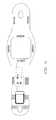
- FIG. 1Adepicts the wearable antenna assembly placed on the waist of a patient.
- FIG. 1Bshows the top view of a wearable antenna assembly on a patient.
- FIG. 2illustrates a three dimensional view of a wearable antenna assembly.
- FIGS. 3A and 3Bshow examples of a static length structural belt.
- FIG. 3Ashows the top view of a structural option for a wearable antenna assembly.
- FIG. 3Bshows the profile view a structural option for a wearable antenna assembly.
- FIGS. 4A , 4 B, 4 Cshow various options for a control panel on a wearable antenna assembly.
- FIG. 5depicts an example block diagram of the structural layers of a flexible transmitting antenna.
- FIG. 6illustrates a wearable antenna assembly with a secondary battery dock.
- FIG. 7illustrates adjustable cabling for circumferential adjustability of the wearable antenna assembly.
- FIG. 8illustrates adjustable cabling in a flexible wearable antenna assembly to allow for stretch flexibility.
- FIGS. 9A-Edemonstrates tensioners used to hold the shape of a flexible transmitting antenna embedded within the wearable antenna assembly to maintain the concave curvature of the individual patient's waist.
- FIG. 9Aillustrates a flexible transmitting antenna embedded within the wearable antenna assembly while the pull-string tensioners are not engaged and the antenna is flat.
- FIG. 9Billustrates a flexible transmitting antenna embedded within the wearable antenna assembly while the pull-string tensioners are engaged and the antenna's flexible shape is maintained.
- FIG. 9Cillustrates a wearable antenna assembly on a patient where the pull-string tensioners are engaged and the embedded antenna's flexible shape conforms to the lumbar crevice of the patient.
- FIG. 9Dillustrates an embedded antenna while the Velcro straps are not engaged and the embedded antenna's flexible shape is not maintained.
- FIG. 9Eillustrates an embedded antenna while the Velcro straps are engaged and the embedded antenna's flexible shape is maintained.
- FIG. 10Aillustrates a wearable antenna assembly with a two-piece antenna with interlocking fingers that give greater conformity to the lumbar crevice.
- FIG. 10Billustrates a two-piece antenna with interlocking fingers that adjust along the caudal-cranial axis.
- FIG. 11demonstrates the use of a soft sleeve that is slipped over the structural portions of the wearable antenna assembly.
- FIG. 12illustrates an embodiment of the wearable antenna assembly with an elastic portion to increase flexibility.
- FIG. 13illustrates various embodiments of flexible transmitting antenna shapes for the wearable antenna assembly.
- FIG. 14depicts the use of venting holes in the wearable antenna assembly for evaporation of sweat and increased breathability.
- FIG. 15is an example of fasteners used to secure the wearable antenna assembly to the patient.
- FIG. 16illustrates a wearable antenna assembly that is condensed to fit into the shape of a standard watch.
- FIG. 17illustrates a fabric-antenna made of micro-conducting fibers woven into a structure of fabric to create a flexible antenna.
- FIGS. 18A-Billustrates the flexible transmitting antenna within the wearable antenna assembly.
- FIG. 18Aillustrates the process of depositing materials to create the antenna stack up.
- FIG. 18Bis a block diagram depicting the antenna layers for an assembly where the dielectric, conducting planes, and foam are deposited in to create an ultra thin profile.
- FIG. 19illustrates a semi-cylindrical array of antennas that are used to transmit power.
- FIG. 20illustrates a molded flexible transmitting antenna that is snapped into the wearable antenna assembly.
- FIG. 21is an example of a molded flexible transmitting antenna that conforms to the lumbar crevice, and can be secured directly to tissue using suction cups.
- FIG. 22illustrates fluid wicking, hydrophilic micro-channels built in to the wearable antenna assembly to displace fluids that would otherwise disrupt the tuning of the antenna.
- FIG. 23is a block diagram depicting the antenna layers for an implementation where perspiration is used in the tuning calculation of the dielectric within the wearable antenna assembly.
- FIG. 24demonstrates an antenna array that can be used to select the antenna that is in the best position to power the lead and reduce reflection within the wearable antenna assembly.
- FIG. 25is an example of a rotary mechanism that allows the antenna to be rotated by 270 degrees within the wearable antenna assembly.
- FIG. 26demonstrates the use of two flexible transmitting antennas within the wearable antenna assembly to power multiple leads simultaneously with distinct parameters.
- FIG. 27is an example circuit that can be used to inform the user that RF energy is being transmitted.
- FIG. 28illustrates the use of signal rails within the belt to allow placement of the battery, control panel, and microwave field stimulator in interchangeable locations along the wearable antenna assembly.
- FIG. 29is an example of a placement of the microwave field stimulator on the wearable antenna assembly.
- FIG. 30illustrates the use of differential positioning sensors placed on the wearable antenna to alert the user and adjust stimulation.
- FIGS. 31 and 32show an example of a belt fastening system with sensor contacts to activate/deactivate the generation of the signal.
- FIG. 33shows a top view of a wearable antenna assembly according to some embodiments of the present invention.
- FIG. 34shows a side view of a wearable antenna assembly according to some embodiments of the present invention.
- FIG. 35Ashows a top view of a wearable antenna assembly with certain outer portions removed according to some embodiments of the present invention.
- FIG. 35Bshows a bottom view of a wearable antenna assembly with certain outer portions removed according to some embodiments of the present invention.
- FIGS. 36A , 36 B, and 36 Cshow cross section cutaway views of portions of a wearable antenna assembly according to some embodiments of the present invention.
- FIG. 37shows a longitudinal cutaway view of a wearable antenna assembly according to some embodiments of the present invention.
- FIG. 38shows an exploded 3 D view of a wearable antenna assembly according to some embodiments of the present invention.
- FIG. 1Ashows an example of a wearable antenna assembly (WAA) on a patient.
- the wearable antenna assemblyincludes a soft flexible belt, an adjustable strap, a replaceable battery, an embedded control panel with interface buttons, an embedded microwave field stimulator (MFS), an embedded flexible transmitting antenna, and cabling.
- MFSembedded microwave field stimulator
- the wearable antenna assemblyis secured around the waist of a patient, or an animal.
- the wearable antenna assemblycan be placed around the body at the horizontal vertebrae levels ranging from L5 to T5.
- the wearable antenna assemblyhas an adjustable circumferential length from about 22 inches to about 50 inches. Examples of a microwave field stimulator, transmitting antenna, and corresponding implantable neural stimulator with receiving antenna are described in U.S.
- the microwave field stimulator attached to the wearable antenna assemblyis powered by a replaceable battery and controlled by an embedded control panel.
- the replaceable batteryis comprised of rechargeable battery chemistry; such as, but not limited to lithium-ion, lithium polymer, nickel cadmium, nickel metal-hydride, etc.
- the replaceable batterycan have a capacity within a range from 0 mAh to 10,000 mAh.
- the replaceable batterycan have a nominal voltage rating from about 1.0 volt to 20 volts.
- the replaceable batterycan be embedded within the wearable antenna assembly and recharged via a wall plug or with wirelessly.
- the microwave field stimulatoris connected to the embedded transmitting antenna, which transmits a radio frequency (RF) signal to an implanted receiving antenna within the tissue of the patient, on the skin of the patient, or within an article of clothing close to the body of the patient.
- the RF signalmay have a characteristic frequency within a range from about 800 MHz to about 6 GHz.
- the embedded transmitting antenna embodied in FIG. 1Ais a directional patch antenna, but other antenna types can be used; such as a monopole, dipole, vagi, whip, or horn antenna.
- FIG. 1Billustrates the top view of a wearable antenna assembly on a patient.
- the embedded control panel, embedded microwave field stimulator, and the embedded transmitting antennaare flexible and can conform to the shape of the patient's back.
- the microwave field stimulator and the transmitting antennaare low profile and streamlined to contour with the patient's body curves. This low profile allows the patient to conceal the wearable antenna assembly under clothing easily.
- FIG. 2shows a three dimensional view of a wearable antenna assembly.
- the adjustable strapcan be made of stretchable, supporting material such as elastic or nylon.
- the adjustable strapcan be removed from the wearable antenna assembly to be washed and replaced with an adjustable strap that is either shorter or longer.
- the width of the adjustable strapcan be within a range from about 0.2 inches to about 5.0 inches.
- the circumferential length of the adjustable strapcan be within a range from about 10 inches to about 60 inches.
- the adjustable strapuses connector tabs that pull through an open slot on the structural wearable antenna assembly and are rotated to lock into place.
- the structural wearable antenna assemblyholds the battery, embedded control panel, embedded microwave field stimulator, and the embedded transmitting antenna.
- the structural wearable antenna assemblycan be made of flexible, semi-rigid materials such as elastomers, rubber, neoprene, and polyurethane.
- the structural wearable antenna assemblycan have a width within a range from 0.2 inch to 5.0 inches.
- the structural wearable antenna assemblycan have a thickness within a range of about 0.1 inches to about 2 inches.
- the length of the structural wearable antenna assemblycan be within a range of about 5 inches to about 20 inches.
- the microwave field stimulatorcan be located within a range from about 0.5 inch to about 12 inches from the embedded transmitting antenna.
- the thickness of the microwave field stimulatorcan be within a range from about 0.08 inches to about 0.39 inches.
- the length of the microwave field stimulatorcan be within a range from about 0.78 inches to about 2.75 inches.
- the width of the microwave field stimulatorcan be within a range from about 0.78 inches to about 2.75 inches.
- the embedded transmitting antennacan have a length and width within a range from about 2 inches to 7 inches.
- the embedded transmitting antennacan have a thickness within a range from about 0.08 inches to about 0.2 inches.
- FIGS. 3A and 3Bshow examples of a static length structural wearable antenna assembly.
- a structural wearable antenna assemblymay include locking slots for an adjustable strap, a replaceable battery, embedded flat wire connectors, an embedded user interface control panel, an embedded microwave field stimulator, an embedded coaxial cable, and an embedded transmitting antenna.
- FIG. 3Athe top view of the structural wearable antenna assembly.
- the replaceable batteryis connected to a battery dock that secures the battery.
- the battery dockuses flat wires that are embedded into the structural wearable antenna assembly to bring power through the control panel and to the microwave field stimulator.
- the control panelalso utilizes multiple flat wires to connect to the microwave field stimulator.
- the microwave field stimulatoroutputs an RF signal through the thin profile coaxial cable that is embedded in the structural wearable antenna assembly to the transmitting antenna.
- the locking slotsare located at opposite horizontal ends of the wearable antenna assembly and connect to an adjustable strap to allow for greater flexibility between patients of different waist sizes.
- FIG. 3Bthe profile view of the structural wearable antenna assembly.
- the replaceable batteryis locked into the embedded dock.
- the control panelshows very low profile buttons that are used to control the microwave field stimulator.
- the microwave field stimulator and embedded antennashow a very low profile that allows the device to conform well to the patient and remove obstructive extrusions.
- Structural belthas conforming curves that allow the transitions of thicknesses of the various components to be smoothed out. The conforming curves aid the patient in avoiding the belt getting caught onto corners and edges of objects that a patient may daily interact with.
- FIGS. 4A , 4 B, 4 Cshow examples of a control panel for the WAA.
- a control panelmay include button-switches to control neurostimulation settings, and a sliding switch that chooses the setting that is being controlled by the switches.
- the WAAmay include only two button-switches. These two-button switches may control the amplitude, pulse width, frequency, or preset programs of stimulation.
- the switchescan be labeled with directional arrows or plus and minus features. In certain embodiments, there may be more than two button-switches that can control a number of parameters from the microwave field stimulator.
- buttons-switchesallow the user to increase (+) or decrease ( ⁇ ) the amplitude of the parameter.
- the soft buttonsare placed at the top of the belt, allowing the user to see the buttons and select the correct change for the selected parameter.
- the soft buttonsalso feature an embossed + and ⁇ so that the user can develop a sensory adaption to the parameter change button without relying on sight.
- the WAAmay include a sliding switch that chooses the setting that is being controlled by the switches.
- the sliding switchcan act as an on/off toggle, in this embodiment the slider is pushed all the way to one end, which interrupts all power and stops stimulation.
- the sliding switchwhen not in the off position, will begin stimulation.
- the slidercan toggle button-switches to adjust specific parameters such as amplitude of power, pulse width, frequency, or preset parameters.
- the toggle switchis positioned in the front face of the belt, which allows the user to see the switch or rely on sensory feedback of the switches resistance to being thrown into position.
- the control panelis streamlined and integrated into the belt.
- This moduleis positioned between the microwave field stimulator and the battery on the belt and is accessible at the front of the belt.
- the usercan use tactical sensory feedback when operating the control panel.
- the toggle switch and the soft buttonsmake the control panel distinguishable from the microwave field stimulator and the battery.
- the control panel's width and lengthcan be within the range from about 0.5 inches to about 2.0 inches.
- the control panel's thicknesscan be within the range from about 0.08 inches to about 0.5 inches.
- the control panelmay have multiple indicator lights used to inform the user of system functions.
- FIG. 5depicts a block diagram of the structural layers of a flexible transmitting antenna.
- the flexible transmitting antennais composed of a conductive layer pitted between equal layers of moldable foam with a ground plane and a dielectric matching layer that is placed against the back of the user.
- the transmitting antennais tuned with a dielectric material to match the coupling of the user's skin eliminating the need for a gel to facilitate transmission.
- the conductive layer of the transmitting antennais composed of a conductive material such as copper, gold, etc.
- the foam layersare comprised of non-conductive materials such as polyimide and secured to the conductive layer with a thin layer of adhesive.
- the antennais capable of transmitting energy through the body to the implanted lead because of the dielectric matching layer.
- This layeris affixed to the transmitting antenna and is in contact with the body while the WAA is worn.
- the antennacan be comprised of a conductive layer pitted between two layers of moldable foam. This antenna construction permits the antenna to be shaped and formed to fit flush against the back of the user eliminating air gaps.
- the ability of the dielectric to match the permittivity of the bodyallows the antenna to perform without the assistance of a gel applied to the body to maintain contact between the skin and the antenna.
- FIG. 6illustrates a design of the WAA to have a secondary battery dock which allows the user to hot-swap batteries for continuous neurostimulation.
- a WAAmay consist of two embedded battery-docking stations. Once the primary battery connected to the MFS is close to drained and the user is informed via LED or notification to smart phone via Bluetooth, the user can place a fully charged secondary replaceable battery into the secondary battery dock to continue stimulation. The user can disengage the drained battery from the belt, once the fully charged battery is in place. The belt-mounted secondary battery dock is positioned next to the primary battery-dock on the user's front side of the belt.
- the stationary battery docks' connectionscan be placed in parallel so that the voltage to the MFS is not doubled, but rather the capacity is increased.
- a usercan have both the primary battery and secondary battery engaged on the WAA to extend the overall charge life of the device.
- FIG. 7illustrates an adjustable coaxial cabling method used for circumferential length adjustability of the structural belt.
- This embodiment of the structural beltincludes a microwave field stimulator that can be moved along the circumferential axis of the belt, while the embedded antenna is stationary.
- the coaxial cableis wound around a small flexible rod that is secured to the structural belt at one end. The rod releases wound cable at one end, allowing the user to wind or unwind the cabling from the rod and adjust the location of the microwave field stimulator for best comfort.
- the amount of adjustable length added from the rodcan be within the range from about 0.5 inches to about 6.0 inches.
- FIG. 8illustrates an adjustable coaxial cabling method in a flexible structural belt to allow flexibility when the belt is stretched.
- a flexible structural beltcan maintain the integrity of the coaxial cable's connectors when the patient is stretching the WAA around the waist.
- the coaxial cableis wrapped around cleats that are attached to multiple scissor hinges.
- the scissor hingesare mounted to the flexible structural belt, and when stretched the scissor hinges expand and the cabling woven over the cleats is elongated.
- the cleat-scissor mechanismallows circumferential length adjustability from about 0.01 inches to about 2.0 inches.
- FIGS. 9A to 9Edemonstrate the tensioners used to ensure that shape of an embedded antenna is maintained while the belt is worn by the user.
- FIG. 9Aillustrates an embedded antenna while the pull-string tensioners are not engaged and the embedded antenna is flat.
- the low-profile cleatspull the structural belt together to push the embedded antenna convexly into the crevice of the lumbar region of the patient, as depicted in FIG. 9C .
- the locking moduleshold the strings in place so that the tension is maintained, as depicted in FIG. 9B .
- FIG. 9Billustrates an embedded antenna while the pull-string tensioners are engaged and the embedded antenna's flexible shape is maintained.
- FIG. 9Cillustrates a WAA on a patient where the pull-string tensioners are engaged and the embedded antenna's flexible shape conforms to the lumbar crevice of the patient.
- FIG. 9Dillustrates an embedded antenna while the Velcro straps are not engaged and the embedded antenna's flexible shape is not maintained.
- the sewn-in anchors of each strappull the structural belt together to push the embedded antenna convexly into the crevice of the lumbar region of the patient.
- FIG. 9Eillustrates an embedded antenna while the Velcro straps are engaged and the embedded antenna's flexible shape is maintained.
- FIG. 10Aillustrates a WAA with a two-piece antenna with interlocking fingers that give greater conformity to the lumbar crevice.
- the interlocking fingers of the antennaautomatically adjust to the patient according to the tightness of the WAA. As the patient tightens or loosens the adjustable portion of the WAA, the interlocking fingers push together to either go convex or concave into the lumbar crevice.
- FIG. 10Billustrates a two-piece antenna with interlocking fingers that adjust along the caudal-cranial axis.
- the antennais composed of the flexible conductive layer between the two, polyamide foam layers secured with an adhesive.
- the antennacomprises of two pieces that lock together.
- the interlocking endscan flex to conform to the crevice of the user's back.
- the antennawill lock tight, but flexibility of the antenna will be maintained at the ends of the antenna to encourage elimination of air between the antenna and the user's back.
- FIG. 11demonstrates the use of a soft sleeve that is slipped over the structural portions of the WAA.
- the sleevehas an opening at each end and shaped to identify the end that is intended for the antenna and an opening for the toggle switch of the control module.
- the sleeveis tubular, designed to fit tightly to the structural belt and to provide additional cushioning for user comfort. Additionally, this tight fitting sleeve streamlines the modules of the belt for concealing the belt under clothing.
- the sleeve materialcan be a water resistant, soft, flexible material such as neoprene or nylon with elastic support threads. The sleeve is machine washable.
- FIG. 12demonstrates the implementation of an elastic portion into a structural belt to increase flexibility between user positions.
- This WAAuses snap-in connectors to secure the structural belt around the user.
- the adjustability of the WAAis isolated to only one side of the belt allowing the user to easily adjust the fit of the belt for comfort, and removal when necessary.
- the user of a singular point of adjustabilityeliminates user errors, or risk of incorrectly adjusting the belt on the body.
- the combination of elasticity and adjustabilityprovides secure fit of the belt to the body when the user is changing positions, i.e. standing to sitting, standing to bending over, sitting to bending over, etc.
- FIG. 13illustrates various patch antenna shapes that can be used in the wearable antenna assembly.
- the interlocking fingers antenna, square antenna, diamond antenna, and rectangular antennaare examples of antennas for the WAA.
- FIG. 14depicts the use of venting holes in the wearable antenna assembly to encourage the evaporation of sweat and increase the breathability of the assembly.
- the structural belthas perforations in the elastomer to permit airflow to the skin.
- the ventilation holespermit the flow of air to the covered area of the skin, which allows natural body perspiration to cool the surface temperature.
- the holesare placed at modules that are potential heat generating modules to ventilate the areas that are more susceptible to perspiration.
- FIG. 15is an example of fasteners used to secure the wearable antenna assembly to the patient.
- Locking fastenerssuch as a tab-slot hole design, a parachute clip, or a Velcro strap may be used on the WAA.
- a sliding clipcan be used to adjust the circumference of the WAA.
- the fastening methodsare easily operated while the belt is worn on the body. The fastener will be secured at the front and adjusted at the side of the user, which should not impede dexterity when attempting to remove or adjust the fit of the belt.
- FIG. 16illustrates a wearable antenna assembly that is condensed to fit into the shape of a standard watch.
- a watchthat contains an embedded antenna, microwave field stimulator, button controls, and replaceable battery can be used to deliver RF to an implanted lead module for peripheral nerve stimulation.
- the transmitting antennais formed into the straps of the watch, with the microwave field stimulator, battery, and button controls are incorporated into the face of the watch.
- the wristwatchmay have an LCD display screen that will visually communicate the stimulation, pulse width, and frequency parameters for the user to update with the buttons, and have functionality similar to standard watches including time, stopwatch, countdown timer, alarm, date, etc.
- FIG. 17illustrates a fabric-antenna made of micro-conducting fibers woven into a structure of fabric to create a flexible antenna.
- the conductive threadscan be made of conductive materials such as gold, copper, etc.
- the conductive threadsare woven into fabric threading to create a flexible and thin patch of conductive material. For tuning of the antenna to specific frequencies, the material would be trimmed or cut to the required length.
- the conductive fabricis then used transmit an RF signal directly to the implant at various locations on the body where fabric is found, including but not limited to: lumbar, thorax, stomach, chest, shoulder, arm, forearm, leg, foot, hand, neck, buttocks, etc.
- the microwave field stimulatorwould be implemented into a separate belt or clip that is held comfortably at the waist or in the pocket.
- FIGS. 18A and Billustrate the implementation of an antenna that is deposited into a WAA.
- FIG. 18Aillustrates the process of depositing materials to create the antenna stackup.
- the structural beltis sprayed with micro-drops of a liquid contained under pressure for precise placement.
- the deposit made by these liquids once drywill form the dielectric and conductive materials of the antenna. This eliminates the need for pitting the antenna into the belt.
- the cablingis run through the belt with a coaxial cable connecting to a copper or gold connector built into the belt. Once sprayed with the liquid, the antenna will be affixed to the coaxial cable.
- FIG. 18Bis a block diagram depicting the antenna layers for an assembly where the dielectric, conducting planes, and foam are deposited in to create an ultra thin profile.
- the transmitting antennais spray molded into the structural belt through spraying in the layers of the antenna to form the antenna to the exact shape of the belt.
- the conductive ground layeris sprayed in first, followed by the layer of sprayed polyamide foam. Once dry the conductive layer is sprayed in followed by a second layer of polyamide foam. Once dry, the matching dielectric layer is laid over the sprayed antenna concealing the antenna from the user.
- the cablingis run through the belt with the coaxial cable connecting to a copper or gold connector built into the belt. Once sprayed with the conductive liquid, the antenna will be affixed to the coaxial cable.
- FIG. 19illustrates a semi-cylindrical array of antennas that are used to transmit power to the implant.
- the semi-cylindrical antenna arrayis comprised of smaller patch antennas that act as a single antenna to transmit RF energy to an implanted lead.
- the smaller antennasare arranged to direct or steer the energy directly to the implant.
- the smaller antennashave small space between them to improve the flexibility of the WAA and conformity of the antennas to the body.
- Each antennais moldable and would conform to the back and body of the user. The moldability of many small antennas improves the ability of the patient to correctly place the belt on the body after removal.
- FIG. 20illustrates a molded antenna that is snapped into the wearable antenna assembly.
- a snap-in molded antennais composed of flexible conductive layers pitted between two layers of moldable dielectric foam attached with adhesive.
- the patchis moldable and attached to the structural belt with elastomer teeth.
- the antennacan be molded independently from the belt, allowing the user to conform the antenna to their body without the risk of the antenna relaxing its shape due to tension from the belt.
- the beltwill fit snug on the user, while maintaining constant contact of the antenna on the user.
- FIG. 21is an example of a molded antenna that conforms to the lumbar crevice, and can be secured directly to tissue using suction cups.
- the suction-cup antennais conformed and affixed to the users back with suction cups.
- the formable antennais designed with rubber suction cups that are able to attach to the back of the user with applied force, creating a vacuum between the antenna and the user. This gives greater conformity of the transmitting antenna to the user's body and will stabilize the antenna over the implant.
- the suction-cup antennais encapsulated with the matching dielectric and is connected via coaxial cable to the microwave field stimulator that is clipped to the belt or in the pocket.
- FIG. 22illustrates fluid wicking, hydrophilic micro-channels built in to the wearable antenna assembly to displace fluids that would otherwise disrupt the tuning of the antenna.
- the elastomer material of the structural beltmay be affixed with moisture pads, made of an absorbent material that is flush with the belt surface.
- the micro-channelsare hydrophilic and draw moisture, such as sweat, away from the antenna face, and direct the moisture through the long narrow channels pitted into the structural belt to the washable moisture pads attached on the inside of the belt.
- the water micro-channelswould be located around the circumference of the WAA, without the use of moisture pads, to displace moisture to less moist regions of the WAA.
- FIG. 23is a block diagram depicting the antenna layers for an implementation where perspiration is used in the tuning calculation of the dielectric within the wearable antenna assembly.
- the embedded antennauses the permittivity of sweat as a form of matching dielectric to allow transmission of energy through the body.
- the secondary layer of matching dielectricis effective for transmission when the body is not perspiring. This layer is similar in permittivity to sweat, but not identical.
- the embedded antennais designed with a conductive layer pitted between two layers of moldable foam. The moldable foam allows the antenna to be flexed and molded to match the shape of the users back. This body shaped antenna maintains contact with the skin encouraging body perspiration to match the dielectric for energy transmission.
- FIG. 24demonstrates an antenna array that can be used to select the antenna that is in the best position to power the lead and reduce reflection within the wearable antenna assembly.
- the WAAis designed to incorporate more than one embedded antenna to power the implanted lead.
- the transmitting antennasare small and are placed in the structural belt.
- the microwave field stimulatoris able to power one, two, three or all four of the antennas to transmit the RF energy to the lead.
- the antenna arrayallows RF energy to be steered towards the implant.
- the microwave field stimulatorcan dynamically calculate the antenna that has the least amount of reflected energy and use the most efficient antenna to power the lead as the user moves around in their daily environment.
- FIG. 25is an example of a rotary mechanism that allows the antenna to be rotated by 270 degrees within the wearable antenna assembly.
- Migration of the implant in the bodycan require repositioning of the WAA antenna within the belt to avoid polarization of transmission and encourage optimized transmission.
- the embedded antennais set into a circular housing in the WAA.
- the antennais secured to the belt with a centered ball joint that allows rotational movement along the arced track of the belt.
- the antennahas a matching pin that aligns to the groove of the track of the belt.
- the arced track for rotationallows rotation between from about 0° to about 270°.
- the ball jointis designed with resistance so that movement of the antenna within the house must be deliberate, requiring force to move the antenna along the track.
- the coaxial cable for the transmitting antennais run through the circular track of the belt. Any slack cabling is wound on its own ball joint, as the antenna rotates. Once the antenna is set at the appropriate rotation for transmission the antenna and cabling can be re-concealed with a sleeve or cover.
- FIG. 26demonstrates the use of two antennas to power two leads simultaneously with separate parameters and amplitudes in the wearable antenna assembly.
- the microwave field stimulatoris able to program and transmit independent power parameters to the two implanted leads. This allows for control over two or more leads, implanted at different locations.
- the antennasare stacked and are able to be placed off center front the spine.
- FIG. 27is an example circuit that can be used to inform the user that RF energy is being transmitted.
- An indicator lightis build into the control panel of the belt. This indicator light illuminates when the belt is transmitting energy to the implant. This indicator light is independent from the “power on” indicator. If the microwave field stimulator is not able to transmit power to the transmitting antenna, the indicator light will not illuminate. This indicator light will remain illuminated as long as RF energy is transmitted out of the embedded antenna.
- This indicator lightcan be a small LED, OLED, LCD, or a signal sent to a smart phone application via Bluetooth. The indicator light works through a small dipole placed at the edge of the embedded antenna, which receives the energy to power the indicator light. A resistor is used to tune the current to the indicator light.
- FIG. 28illustrates the use of signal rails within the belt to allow placement of the battery, control panel, and microwave field stimulator in interchangeable locations along the wearable antenna assembly.
- the microwave field stimulator, battery, and control panelare “floating” modules on the belt. These modules are secured to the belt via tracks and conduct energy/signal through the rails. In certain embodiments, the tracks are keyed so as to prevent incorrect orientation of the modules connecting to the wrong rails.
- the modulescomplete their circuitry once attached to the belt set into the tracks. The modules are then secured on the belt. The user is able to move the modules independent of each other allowing the user to place the modules on comfortable places on the belt.
- the various body sizes and shapesrequire the modules to be adjustable.
- the railscan be set for specific signals including but not limited to: battery-power, ground, button-switches, RF Signal, light indicator.
- FIG. 29is an example of the placement of the microwave field stimulator near the antenna on the wearable antenna assembly.
- the microwave field stimulatoris positioned close to the transmitting antenna on the belt to reduce transmission loss from the cable. This allows for a shorter, lower-profile cable.
- the microwave field stimulatorcan be located on either side of the antenna. In certain embodiments, the microwave field stimulator may be located on the backside of the antenna.
- FIG. 30illustrates the use of differential positioning sensors placed on the wearable antenna to alert the user and adjust stimulation.
- the beltis affixed with positioning sensors that will alert the user if the belt shifts to a position on the body that could produce less than optimal transmission of RF energy to the implanted lead.
- the dorsal sensorscan be placed on the belt close to the transmitting antenna.
- the ventral sensorscan be placed at the belt clip or at the 180° mark from the antenna.
- the microwave field stimulatorcalculates the differential position between the ventral and dorsal aspects of the WAA and can alert the user when the WAA has shifted enough that transmission may be interrupted.
- the microwave field stimulatorcan calculate the differential position between the ventral dorsal aspects of the WAA and automatically adjust the amplitude when the user has changed positions that are known to need corrective actions.
- the indication to the usercan be vibration from the microwave field stimulator. Until the user has corrected the placement, the microwave field stimulator can vibrate or alert the user through a smartphone app via Bluetooth.
- FIGS. 31 and 32show an example of a belt fastening system with sensor contacts to activate/deactivate wireless stimulating electronics.
- the fastenercontains male electrical contacts on the female side of the parachute clip and female electrical contacts on the male side of the parachute clip.
- the contactscan be connected to the circuitry of the battery.
- the circuitis closed, allowing the battery to power the microwave field stimulator.
- the circuitis open, disabling the power from the battery to the microwave field stimulator.
- the electrical contactscan be used as a smart sensor to notify the electronics that the user is going to take off or adjust the belt. The microwave field stimulator could then slowly power down the amplitude of stimulation to avoid uncomfortable VSWR interactions with the antenna and the patient.
- FIG. 33shows a top view of a wearable antenna assembly according to some embodiments of the present invention.
- a center portion 3300is disposed toward the longitudinal middle of the wearable antenna assembly.
- Left portion 3310 and right portion 3320are disposed at either longitudinal side of center portion 3300 .
- control panel 3330is provided on the top face of right portion 3320 .
- Fastening members 3340are provided to allow fastening of an elastic belt or otherwise to the portion of the wearable antenna assembly shown.
- the portion of the wearable antenna assembly as shown in FIG. 33may be less than the full length of a full wearable antenna assembly.
- the portion of wearable antenna assembly shown in FIG. 33may be approximately 30 centimeters long.
- An elastic ban attached at each end to fastening members 3340can then be provided to make the full length or circumference of the entire wearable antenna assembly the length desired.
- an elastic bandwill be provided so that the entire wearable antenna assembly circumference including the elastic band and the portion shown in FIG. 33 will be wearable around the torso of a patient, as previously discussed. Nonetheless, other configurations are possible, such as using a different attachment to fastening members 3340 , different forms of fastening members than those shown in FIG. 33 , different lengths of attachments to fastening members 3340 , and a different length for the portion shown in FIG. 33 .
- FIG. 34shows a side view of a wearable antenna assembly according to some embodiments of the present invention.
- center portion 3300is disposed longitudinally between left portion 3310 and right portion 3320 .
- narrower portions between center portion 3300 and left portion 3310 and between center portion 3300 and right portion 3320may be provided to allow the wearable antenna assembly to flex and contour to the patient's body.
- These portionsmay also or alternatively be provided as a flexible material, such as foam, rubber, or otherwise.
- FIG. 35Ashows a top view of a wearable antenna assembly with certain outer portions removed according to some embodiments of the present invention.
- center portion 3300contains a MFS 3500 and a transmitting antenna 3505 .
- Transmitting antenna 3505may be a patch antenna provided in the center of center portion 3300 .
- MFS 3500may be a provided as a printed circuit board with various circuitry provided thereon. As shown, MFS 3500 may be provided as disposed essentially surrounding transmitting antenna 3505 .
- Left portion 3310contains left battery 3510 .
- Right portion 3320contains control panel 3310 as well as right battery 3520 provided below control panel 3310 .
- FIG. 35Bshows a bottom view of a wearable antenna assembly with certain outer portions removed according to some embodiments of the present invention.
- center portion 3300contains MFS 3500 and transmitting antenna 3505 .
- Left portion 3310contains wireless charging coil 3515 as well as left battery 3510 provided below wireless charging coild 3515 .
- Right portion 3320contains right battery 3520 .
- FIGS. 36A , 36 B, and 36 Cshow cross section cutaway views of portions of a wearable antenna assembly according to some embodiments of the present invention.
- FIG. 36Ashows a cross section cutaway view of center portion 3300 .
- transmitting antenna 3505is disposed in the middle of center portion 3300 .
- MFS 3500is disposed in the area surrounding transmitting antenna 3505 .
- FIG. 36Bshows a cross section cutaway view of right portion 3320 .
- right battery 3520is provided therein, and control panel 3330 is provided on the top face of right portion 3320 .
- FIG. 36Cshows a cross section cutaway view of left portion 3310 . As shown, left battery 3510 and wireless charging coil 3515 are provided therein.
- FIG. 37shows a longitudinal cutaway view of a wearable antenna assembly according to some embodiments of the present invention.
- transmitting antenna 3505 and MFS 3500are provided in center portion 3300 .
- right battery 3520 and control panel 3330are provided in right portion 3320 .
- left battery 3510 and wireless charging coil 3515are provided therein are provided in left portion 3310 .
- FIG. 38shows an exploded 3 D view of a wearable antenna assembly according to some embodiments of the present invention.
- center portion 3300which contains MFS 3500 and transmitting antenna 3505 , may contain a top rigid cover 3810 and a bottom rigid cover 3815 .
- top rigid cover 3810 and bottom rigid cover 3815close around MFS 3500 and transmitting antenna 3505 to form a rigid, protective shell around those components.
- This rigid shell along with the other components previously discussedmay then be enclosed in top skin 3800 and bottom skin 3805 .
- Top skin 3800 and bottom skin 3805may serve to maintain all of the various functional components contained an in place in the wearable antenna assembly. Furthermore, top skin 3800 and bottom skin 3805 may be provided as a flexible material. With such a configuration, the wearable antenna assembly shown in this figure may be sufficiently flexible to contour to the patient's body despite the rigid components contained therein. As such, the flexible material of top skin 3800 and bottom skin 3805 may allow the wearable antenna assembly as shown in this figure to be worn as a belt despite it containing various rigid components.
- elements shown as integrally formedmay be constructed of multiple parts or elements.
- the elements and assembliesmay be constructed from any of a wide variety of materials that provide sufficient strength or durability, in any of a wide variety of colors, textures, and combinations.
- the word “exemplary”is used to mean serving as an example, instance, or illustration. Any embodiment or design described herein as “exemplary” is not necessarily to be construed as preferred or advantageous over other embodiments or designs. Rather, use of the word “exemplary” is intended to present concepts in a concrete manner. Accordingly, all such modifications are intended to be included within the scope of the present disclosure. Other substitutions, modifications, changes, and omissions may be made in the design, operating conditions, and arrangement of the preferred and other exemplary embodiments without departing from the scope of the appended claims.
Landscapes
- Health & Medical Sciences (AREA)
- Physics & Mathematics (AREA)
- Radiology & Medical Imaging (AREA)
- Engineering & Computer Science (AREA)
- Biomedical Technology (AREA)
- Nuclear Medicine, Radiotherapy & Molecular Imaging (AREA)
- Life Sciences & Earth Sciences (AREA)
- Animal Behavior & Ethology (AREA)
- General Health & Medical Sciences (AREA)
- Public Health (AREA)
- Veterinary Medicine (AREA)
- Acoustics & Sound (AREA)
- Electromagnetism (AREA)
- Electrotherapy Devices (AREA)
- Radiation-Therapy Devices (AREA)
Abstract
Description
Claims (18)
Priority Applications (4)
| Application Number | Priority Date | Filing Date | Title |
|---|---|---|---|
| US14/141,197US9254393B2 (en) | 2012-12-26 | 2013-12-26 | Wearable antenna assembly |
| US15/002,593US10293169B2 (en) | 2012-12-26 | 2016-01-21 | Wearable antenna assembly |
| US16/382,406US11583683B2 (en) | 2012-12-26 | 2019-04-12 | Wearable antenna assembly |
| US18/111,011US20230302283A1 (en) | 2012-12-26 | 2023-02-17 | Wearable Antenna Assembly |
Applications Claiming Priority (2)
| Application Number | Priority Date | Filing Date | Title |
|---|---|---|---|
| US201261745952P | 2012-12-26 | 2012-12-26 | |
| US14/141,197US9254393B2 (en) | 2012-12-26 | 2013-12-26 | Wearable antenna assembly |
Related Child Applications (1)
| Application Number | Title | Priority Date | Filing Date |
|---|---|---|---|
| US15/002,593ContinuationUS10293169B2 (en) | 2012-12-26 | 2016-01-21 | Wearable antenna assembly |
Publications (2)
| Publication Number | Publication Date |
|---|---|
| US20140180365A1 US20140180365A1 (en) | 2014-06-26 |
| US9254393B2true US9254393B2 (en) | 2016-02-09 |
Family
ID=50975538
Family Applications (4)
| Application Number | Title | Priority Date | Filing Date |
|---|---|---|---|
| US14/141,197Active2034-01-01US9254393B2 (en) | 2012-12-26 | 2013-12-26 | Wearable antenna assembly |
| US15/002,593ActiveUS10293169B2 (en) | 2012-12-26 | 2016-01-21 | Wearable antenna assembly |
| US16/382,406ActiveUS11583683B2 (en) | 2012-12-26 | 2019-04-12 | Wearable antenna assembly |
| US18/111,011PendingUS20230302283A1 (en) | 2012-12-26 | 2023-02-17 | Wearable Antenna Assembly |
Family Applications After (3)
| Application Number | Title | Priority Date | Filing Date |
|---|---|---|---|
| US15/002,593ActiveUS10293169B2 (en) | 2012-12-26 | 2016-01-21 | Wearable antenna assembly |
| US16/382,406ActiveUS11583683B2 (en) | 2012-12-26 | 2019-04-12 | Wearable antenna assembly |
| US18/111,011PendingUS20230302283A1 (en) | 2012-12-26 | 2023-02-17 | Wearable Antenna Assembly |
Country Status (3)
| Country | Link |
|---|---|
| US (4) | US9254393B2 (en) |
| EP (1) | EP2938393A1 (en) |
| WO (1) | WO2014105973A1 (en) |
Cited By (27)
| Publication number | Priority date | Publication date | Assignee | Title |
|---|---|---|---|---|
| US9409029B2 (en) | 2014-05-12 | 2016-08-09 | Micron Devices Llc | Remote RF power system with low profile transmitting antenna |
| US9564777B2 (en) | 2014-05-18 | 2017-02-07 | NeuSpera Medical Inc. | Wireless energy transfer system for an implantable medical device using a midfield coupler |
| US9566449B2 (en) | 2011-01-28 | 2017-02-14 | Micro Devices, LLC | Neural stimulator system |
| US9610457B2 (en) | 2013-09-16 | 2017-04-04 | The Board Of Trustees Of The Leland Stanford Junior University | Multi-element coupler for generation of electromagnetic energy |
| US9757571B2 (en) | 2011-01-28 | 2017-09-12 | Micron Devices Llc | Remote control of power or polarity selection for a neural stimulator |
| US9789314B2 (en) | 2011-04-04 | 2017-10-17 | Micron Devices Llc | Implantable lead |
| US9974965B2 (en) | 2011-09-15 | 2018-05-22 | Micron Devices Llc | Relay module for implant |
| US10315039B2 (en) | 2011-01-28 | 2019-06-11 | Stimwave Technologies Incorporated | Microwave field stimulator |
| US10874868B1 (en) | 2020-03-31 | 2020-12-29 | Micron Medical Llc | Antenna assembly |
| US10953228B2 (en) | 2011-04-04 | 2021-03-23 | Stimwave Technologies Incorporated | Implantable lead |
| US11116975B2 (en) | 2015-11-09 | 2021-09-14 | Bluewind Medical Ltd. | Optimization of application of current |
| US11213685B2 (en) | 2017-06-13 | 2022-01-04 | Bluewind Medical Ltd. | Antenna configuration |
| US20220016430A1 (en)* | 2016-03-21 | 2022-01-20 | Nalu Medical, Inc. | Devices and methods for positioning external devices in relation to implanted devices |
| US11278719B2 (en) | 2012-12-06 | 2022-03-22 | Bluewind Medical Ltd. | Delivery of implantable neurostimulators |
| US11338148B2 (en) | 2015-05-15 | 2022-05-24 | NeuSpera Medical Inc. | External power devices and systems |
| US11400299B1 (en) | 2021-09-14 | 2022-08-02 | Rainbow Medical Ltd. | Flexible antenna for stimulator |
| US11439833B2 (en) | 2016-11-23 | 2022-09-13 | Bluewind Medical Ltd. | Implant-delivery tool |
| US11583683B2 (en) | 2012-12-26 | 2023-02-21 | Stimwave Technologies Incorporated | Wearable antenna assembly |
| US11648410B2 (en) | 2012-01-26 | 2023-05-16 | Bluewind Medical Ltd. | Wireless neurostimulators |
| US11664585B2 (en) | 2018-07-23 | 2023-05-30 | Ohio State Innovation Foundation | Bio-matched antenna |
| US11766561B2 (en) | 2016-07-18 | 2023-09-26 | Nalu Medical, Inc. | Methods and systems for treating pelvic disorders and pain conditions |
| US11826569B2 (en) | 2017-02-24 | 2023-11-28 | Nalu Medical, Inc. | Apparatus with sequentially implanted stimulators |
| US12115374B2 (en) | 2011-01-28 | 2024-10-15 | Curonix Llc | Microwave field stimulator |
| US12151107B2 (en) | 2018-02-01 | 2024-11-26 | Curonix Llc | Systems and methods to sense stimulation electrode tissue impedance |
| US12186563B2 (en) | 2014-06-21 | 2025-01-07 | Nalu Medical, Inc. | Method and apparatus for neuromodulation treatments of pain and other conditions |
| US12201829B2 (en) | 2017-05-09 | 2025-01-21 | Nalu Medical, Inc. | Stimulation apparatus |
| US12390650B2 (en) | 2016-12-30 | 2025-08-19 | Nalu Medical, Inc. | Stimulation apparatus |
Families Citing this family (35)
| Publication number | Priority date | Publication date | Assignee | Title |
|---|---|---|---|---|
| US9129503B2 (en)* | 2012-11-07 | 2015-09-08 | Malcolm Larry Borlenghi | Locking GPS device for locating children |
| US20140306686A1 (en)* | 2013-04-10 | 2014-10-16 | Alan David Haddy | User Mountable Utility Location Antenna |
| US11229789B2 (en) | 2013-05-30 | 2022-01-25 | Neurostim Oab, Inc. | Neuro activator with controller |
| CA2913074C (en) | 2013-05-30 | 2023-09-12 | Graham H. Creasey | Topical neurological stimulation |
| USD730278S1 (en)* | 2013-06-04 | 2015-05-26 | Enrico Licciardello, Jr. | Battery pack belt |
| KR102340794B1 (en)* | 2014-05-01 | 2021-12-21 | 삼성전자주식회사 | Wearable Device and Method for Controlling the Wearable Device |
| USD752762S1 (en)* | 2014-08-07 | 2016-03-29 | Micron Devices Llc | External transmit modulator for an implantable neural stimulator |
| USD752761S1 (en)* | 2014-08-07 | 2016-03-29 | Micron Devices Llc | External transit modulator for implantable neural stimulator |
| EP3241256A4 (en)* | 2014-12-31 | 2018-08-01 | Micron Devices LLC | Patch antenna assembly |
| JP6751718B2 (en)* | 2015-01-09 | 2020-09-09 | アクソニクス モジュレーション テクノロジーズ インコーポレイテッド | Mounting devices and related methods for use with neurostimulation charging devices |
| GB201500509D0 (en)* | 2015-01-13 | 2015-02-25 | Roxan Developments Ltd | Antenna for identification tag and identification tag with antenna |
| US11077301B2 (en) | 2015-02-21 | 2021-08-03 | NeurostimOAB, Inc. | Topical nerve stimulator and sensor for bladder control |
| US9653786B2 (en)* | 2015-06-27 | 2017-05-16 | Intel Corporation | Wearable antenna system |
| EP3316399B1 (en)* | 2015-07-17 | 2021-11-24 | Sony Group Corporation | Antenna device and module device |
| US10734713B2 (en) | 2016-04-27 | 2020-08-04 | Fractus Antennas, S.L. | Ground plane booster antenna technology for wearable devices |
| US10615489B2 (en)* | 2016-06-08 | 2020-04-07 | Futurewei Technologies, Inc. | Wearable article apparatus and method with multiple antennas |
| US10541468B2 (en)* | 2016-07-28 | 2020-01-21 | Stimwave Technologies Incorporated | Fabric antenna |
| JP7152845B2 (en)* | 2017-04-27 | 2022-10-13 | 株式会社 Mtg | muscle electrostimulator |
| US10542647B2 (en)* | 2017-07-11 | 2020-01-21 | Asustek Computer Inc. | Electronic device and belt-shaped cover thereof |
| CN111601636A (en) | 2017-11-07 | 2020-08-28 | Oab神经电疗科技公司 | Non-invasive neural activator with adaptive circuit |
| JP6934230B2 (en)* | 2018-02-21 | 2021-09-15 | 日本電業工作株式会社 | Antenna structure |
| US11266841B1 (en)* | 2018-06-01 | 2022-03-08 | Stimwave Technologies Incorporated | Securing antennas to wearable articles |
| US10799706B2 (en) | 2018-09-06 | 2020-10-13 | NeuSpera Medical Inc. | Garment for positioning midfield transmitter relative to implanted receiver |
| RU194111U1 (en)* | 2019-04-26 | 2019-11-28 | Общество с ограниченной ответственностью "Альматек" | ELECTRIC PULSES MANAGEMENT DEVICE DEVICE FOR TRANSLINGUAL NEUROSTIMULATION |
| WO2020264214A1 (en) | 2019-06-26 | 2020-12-30 | Neurostim Technologies Llc | Non-invasive nerve activator with adaptive circuit |
| GB201913086D0 (en)* | 2019-09-11 | 2019-10-23 | Univ Oslo Hf | On-body antenna for wireless communication with medical implant |
| CN112886200B (en)* | 2019-11-29 | 2022-08-05 | RealMe重庆移动通信有限公司 | Wearable device |
| CN114728161A (en) | 2019-12-16 | 2022-07-08 | 神经科学技术有限责任公司 | Non-invasive neural activator with boosted charge delivery |
| US10819040B1 (en) | 2020-03-24 | 2020-10-27 | Micron Medical Llc | Antenna having dipole pairs |
| US11955734B2 (en) | 2020-12-29 | 2024-04-09 | Uro Medical Corporation | Antenna for high-permittivity media |
| US20230153555A1 (en)* | 2021-11-18 | 2023-05-18 | Djb Group Llc | Rfid reader control integrated with smart garment |
| US20240306993A1 (en)* | 2023-03-16 | 2024-09-19 | Know Labs, Inc. | Reconfigurable wearable health monitoring device |
| JP2024137560A (en)* | 2023-03-25 | 2024-10-07 | 深▲せん▼市港基電技術有限公司 | Low Frequency Therapy Device |
| CN117065210B (en)* | 2023-05-31 | 2024-06-21 | 上海杉翎医疗科技有限公司 | Device for stimulating peripheral nerves |
| GB202313154D0 (en)* | 2023-08-30 | 2023-10-11 | Borra Daniel | Engines |
Citations (12)
| Publication number | Priority date | Publication date | Assignee | Title |
|---|---|---|---|---|
| US20030169207A1 (en)* | 2002-03-05 | 2003-09-11 | Precision Dynamics Corporation | Microstrip antenna for an identification appliance |
| US20040167587A1 (en)* | 2002-09-30 | 2004-08-26 | Medtronic, Inc. | Multi-mode programmer for medical device communication |
| US20060161225A1 (en)* | 1998-09-04 | 2006-07-20 | Wolfe Research Pty Ltd | Medical implant system |
| WO2006113802A2 (en) | 2005-04-19 | 2006-10-26 | Compex Technologies, Inc. | Device for administering electrode stimulation of back and abdominal muscles |
| US20100168818A1 (en)* | 2008-12-31 | 2010-07-01 | Michael William Barror | External RF Telemetry Module for Implantable Medical Devices |
| US20100198307A1 (en)* | 2003-10-02 | 2010-08-05 | Medtronic, Inc. | Medical device programmer |
| US20110172733A1 (en)* | 2006-02-16 | 2011-07-14 | Imthera Medical, Inc. | Apparatus, system and method for therapeutic treatment of obstructive sleep apnea |
| US20110245892A1 (en)* | 2010-04-05 | 2011-10-06 | Medtronic, Inc. | Flexible recharge coil techniques |
| US20120158407A1 (en)* | 2008-10-10 | 2012-06-21 | Milux Holding Sa | Voice control system for an implant |
| US20120283800A1 (en)* | 2011-01-28 | 2012-11-08 | Stimwave Technologies Incorporated | Neural Stimulator System |
| US20130066400A1 (en) | 2011-01-28 | 2013-03-14 | Stimwave Technologies Incorporated | Microwave field stimulator |
| US20130310901A1 (en)* | 2012-05-21 | 2013-11-21 | Neural Diabetes, Llc | Methods and devices for modulating excitable tissue of the exiting spinal nerves |
Family Cites Families (253)
| Publication number | Priority date | Publication date | Assignee | Title |
|---|---|---|---|---|
| US2990547A (en) | 1959-07-28 | 1961-06-27 | Boeing Co | Antenna structure |
| US3662758A (en) | 1969-06-30 | 1972-05-16 | Mentor Corp | Stimulator apparatus for muscular organs with external transmitter and implantable receiver |
| US3663758A (en) | 1970-03-24 | 1972-05-16 | Teaching Complements Inc | Speech pattern recognition system |
| US3727616A (en) | 1971-06-15 | 1973-04-17 | Gen Dynamics Corp | Electronic system for the stimulation of biological systems |
| FR2283590A1 (en) | 1974-08-30 | 1976-03-26 | Commissariat Energie Atomique | NERVOUS STIMULATION PROCESS AND APPLICATION STIMULATOR OF THE PROCESS |
| US4102344A (en) | 1976-11-15 | 1978-07-25 | Mentor Corporation | Stimulator apparatus for internal body organ |
| US4223679A (en) | 1979-02-28 | 1980-09-23 | Pacesetter Systems, Inc. | Telemetry means for tissue stimulator system |
| US4612934A (en) | 1981-06-30 | 1986-09-23 | Borkan William N | Non-invasive multiprogrammable tissue stimulator |
| US4793353A (en) | 1981-06-30 | 1988-12-27 | Borkan William N | Non-invasive multiprogrammable tissue stimulator and method |
| DE3130104A1 (en) | 1981-07-30 | 1983-02-17 | Messerschmitt-Bölkow-Blohm GmbH, 8000 München | ARRANGEMENT FOR STIMULATING A HUMAN MUSCLE |
| JPS5889075A (en) | 1981-11-24 | 1983-05-27 | Hitachi Ltd | Resonance type switching power source |
| US4494950A (en) | 1982-01-19 | 1985-01-22 | The Johns Hopkins University | Plural module medication delivery system |
| US4561443A (en) | 1983-03-08 | 1985-12-31 | The Johns Hopkins University | Coherent inductive communications link for biomedical applications |
| US4532930A (en) | 1983-04-11 | 1985-08-06 | Commonwealth Of Australia, Dept. Of Science & Technology | Cochlear implant system for an auditory prosthesis |
| AU569636B2 (en) | 1984-09-07 | 1988-02-11 | University Of Melbourne, The | Bipolar paired pulse supplied prosthetic device |
| US4741339A (en) | 1984-10-22 | 1988-05-03 | Cochlear Pty. Limited | Power transfer for implanted prostheses |
| EP0200321A3 (en) | 1985-03-20 | 1987-03-11 | Ingeborg J. Hochmair | Transcutaneous signal transmission system |
| US4592359A (en) | 1985-04-02 | 1986-06-03 | The Board Of Trustees Of The Leland Stanford Junior University | Multi-channel implantable neural stimulator |
| US4665896A (en)* | 1985-07-22 | 1987-05-19 | Novacor Medical Corporation | Power supply for body implant and method of use |
| US4628933A (en) | 1985-07-23 | 1986-12-16 | Michelson Robin P | Method and apparatus for visual prosthesis |
| US4726378A (en)* | 1986-04-11 | 1988-02-23 | Minnesota Mining And Manufacturing Company | Adjustable magnetic supercutaneous device and transcutaneous coupling apparatus |
| US4736747A (en)* | 1986-04-11 | 1988-04-12 | Minnesota Mining And Manufacturing Company | Adjustable magnetic supercutaneous device and transcutaneous coupling apparatus |
| US4837049A (en) | 1986-06-17 | 1989-06-06 | Alfred E. Mann Foundation For Scientific Research | Method of making an electrode array |
| US4750499A (en) | 1986-08-20 | 1988-06-14 | Hoffer Joaquin A | Closed-loop, implanted-sensor, functional electrical stimulation system for partial restoration of motor functions |
| US4736752A (en) | 1986-11-28 | 1988-04-12 | Axelgaard Manufacturing Co., Ltd. | Transcutaneous medical electrode |
| US4926879A (en)* | 1988-06-13 | 1990-05-22 | Sevrain-Tech, Inc. | Electro-tactile stimulator |
| US5058581A (en) | 1990-02-20 | 1991-10-22 | Siemens-Pacesetter, Inc. | Telemetry apparatus and method for implantable tissue stimulator |
| US5314458A (en) | 1990-06-01 | 1994-05-24 | University Of Michigan | Single channel microstimulator |
| US5262793A (en) | 1991-11-18 | 1993-11-16 | Winegard Company | Low profile television antenna for vehicles |
| US5193539A (en) | 1991-12-18 | 1993-03-16 | Alfred E. Mann Foundation For Scientific Research | Implantable microstimulator |
| US5358514A (en) | 1991-12-18 | 1994-10-25 | Alfred E. Mann Foundation For Scientific Research | Implantable microdevice with self-attaching electrodes |
| US5343766A (en) | 1992-02-25 | 1994-09-06 | C & J Industries, Inc. | Switched capacitor transducer |
| JPH05245215A (en) | 1992-03-03 | 1993-09-24 | Terumo Corp | Heart pace maker |
| US5626630A (en) | 1994-10-13 | 1997-05-06 | Ael Industries, Inc. | Medical telemetry system using an implanted passive transponder |
| US5583510A (en) | 1994-11-16 | 1996-12-10 | International Business Machines Corporation | Planar antenna in the ISM band with an omnidirectional pattern in the horizontal plane |
| US5591217A (en) | 1995-01-04 | 1997-01-07 | Plexus, Inc. | Implantable stimulator with replenishable, high value capacitive power source and method therefor |
| US5735887A (en) | 1996-12-10 | 1998-04-07 | Exonix Corporation | Closed-loop, RF-coupled implanted medical device |
| US6164284A (en) | 1997-02-26 | 2000-12-26 | Schulman; Joseph H. | System of implantable devices for monitoring and/or affecting body parameters |
| WO1998037926A1 (en) | 1997-02-26 | 1998-09-03 | Alfred E. Mann Foundation For Scientific Research | Battery-powered patient implantable device |
| US5991664A (en) | 1997-03-09 | 1999-11-23 | Cochlear Limited | Compact inductive arrangement for medical implant data and power transfer |
| US5861019A (en) | 1997-07-25 | 1999-01-19 | Medtronic Inc. | Implantable medical device microstrip telemetry antenna |
| US6458157B1 (en) | 1997-08-04 | 2002-10-01 | Suaning Gregg Joergen | Retinal stimulator |
| US6647296B2 (en) | 1997-10-27 | 2003-11-11 | Neuropace, Inc. | Implantable apparatus for treating neurological disorders |
| US5995874A (en) | 1998-02-09 | 1999-11-30 | Dew Engineering And Development Limited | Transcutaneous energy transfer device |
| US6175752B1 (en) | 1998-04-30 | 2001-01-16 | Therasense, Inc. | Analyte monitoring device and methods of use |
| US6141588A (en) | 1998-07-24 | 2000-10-31 | Intermedics Inc. | Cardiac simulation system having multiple stimulators for anti-arrhythmia therapy |
| US6611715B1 (en) | 1998-10-26 | 2003-08-26 | Birinder R. Boveja | Apparatus and method for neuromodulation therapy for obesity and compulsive eating disorders using an implantable lead-receiver and an external stimulator |
| US6615081B1 (en) | 1998-10-26 | 2003-09-02 | Birinder R. Boveja | Apparatus and method for adjunct (add-on) treatment of diabetes by neuromodulation with an external stimulator |
| AU2492000A (en) | 1999-01-06 | 2000-07-24 | Ball Semiconductor Inc. | Implantable neuro-stimulator |
| WO2000041764A1 (en)* | 1999-01-11 | 2000-07-20 | Bmr Research & Development Limited | An electrotherapy device and method |
| US6350335B1 (en) | 1999-02-16 | 2002-02-26 | Lucent Technologies Inc. | Microstrip phase shifters |
| US6463336B1 (en) | 1999-04-01 | 2002-10-08 | Mmtc, Inc | Active bandage suitable for applying pulsed radio-frequencies or microwaves to the skin for medical purposes |
| US6684104B2 (en) | 1999-04-14 | 2004-01-27 | Transneuronix, Inc. | Gastric stimulator apparatus and method for installing |
| US6445955B1 (en) | 1999-07-08 | 2002-09-03 | Stephen A. Michelson | Miniature wireless transcutaneous electrical neuro or muscular-stimulation unit |
| US7177690B2 (en) | 1999-07-27 | 2007-02-13 | Advanced Bionics Corporation | Implantable system having rechargeable battery indicator |
| US6516227B1 (en) | 1999-07-27 | 2003-02-04 | Advanced Bionics Corporation | Rechargeable spinal cord stimulator system |
| US6442434B1 (en) | 1999-10-19 | 2002-08-27 | Abiomed, Inc. | Methods and apparatus for providing a sufficiently stable power to a load in an energy transfer system |
| WO2001032114A1 (en)* | 1999-11-02 | 2001-05-10 | Wizcare Ltd. | Skin-gripper |
| JP4304558B2 (en) | 1999-11-14 | 2009-07-29 | ソニー株式会社 | Portable device |
| US6364889B1 (en) | 1999-11-17 | 2002-04-02 | Bayer Corporation | Electronic lancing device |
| JP2001211018A (en) | 2000-01-28 | 2001-08-03 | Matsushita Electric Ind Co Ltd | Antenna device and wristwatch-type wireless device using the same |
| US6466822B1 (en) | 2000-04-05 | 2002-10-15 | Neuropace, Inc. | Multimodal neurostimulator and process of using it |
| AU5211500A (en) | 2000-05-05 | 2001-11-20 | Nokia Corporation | Base station of a communication network, preferably of a mobile telecommunication network |
| JP2004521673A (en) | 2000-11-16 | 2004-07-22 | ポリヴァロール ソシエテ オン コマンディテ | In-vivo electronic implant and its artificial vision system |
| USD460430S1 (en) | 2000-12-28 | 2002-07-16 | Seiko Instruments Inc. | Mobile phone |
| WO2002065901A2 (en)* | 2000-12-29 | 2002-08-29 | Ares Medical, Inc. | Sleep apnea risk evaluation |
| US6445953B1 (en) | 2001-01-16 | 2002-09-03 | Kenergy, Inc. | Wireless cardiac pacing system with vascular electrode-stents |
| US6675045B2 (en) | 2001-01-16 | 2004-01-06 | Cardiac Pacemakers, Inc. | Split-can dipole antenna for an implantable medical device |
| US6889086B2 (en) | 2001-04-06 | 2005-05-03 | Cardiac Pacemakers, Inc. | Passive telemetry system for implantable medical device |
| US6662052B1 (en) | 2001-04-19 | 2003-12-09 | Nac Technologies Inc. | Method and system for neuromodulation therapy using external stimulator with wireless communication capabilites |
| WO2003026736A2 (en) | 2001-09-28 | 2003-04-03 | Northstar Neuroscience, Inc. | Methods and implantable apparatus for electrical therapy |
| US20070213773A1 (en) | 2001-10-26 | 2007-09-13 | Hill Michael R | Closed-Loop Neuromodulation for Prevention and Treatment of Cardiac Conditions |
| US6993393B2 (en) | 2001-12-19 | 2006-01-31 | Cardiac Pacemakers, Inc. | Telemetry duty cycle management system for an implantable medical device |
| US7231252B2 (en) | 2002-01-21 | 2007-06-12 | Neopraxis Pty Ltd. | FES stimulator having multiple bundled leads |
| US7317948B1 (en) | 2002-02-12 | 2008-01-08 | Boston Scientific Scimed, Inc. | Neural stimulation system providing auto adjustment of stimulus output as a function of sensed impedance |
| US7853333B2 (en) | 2002-04-08 | 2010-12-14 | Ardian, Inc. | Methods and apparatus for multi-vessel renal neuromodulation |
| US7620451B2 (en) | 2005-12-29 | 2009-11-17 | Ardian, Inc. | Methods and apparatus for pulsed electric field neuromodulation via an intra-to-extravascular approach |
| US7483748B2 (en) | 2002-04-26 | 2009-01-27 | Medtronic, Inc. | Programmable waveform pulses for an implantable medical device |
| US7110823B2 (en) | 2002-06-11 | 2006-09-19 | Advanced Bionics Corporation | RF telemetry link for establishment and maintenance of communications with an implantable device |
| ES2426255T3 (en) | 2002-06-28 | 2013-10-22 | Boston Scientific Neuromodulation Corporation | Microstimulator that has a built-in power source and a two-way telemetry system |
| US8386048B2 (en) | 2002-06-28 | 2013-02-26 | Boston Scientific Neuromodulation Corporation | Systems and methods for communicating with or providing power to an implantable stimulator |
| US7047079B2 (en) | 2002-07-26 | 2006-05-16 | Advanced Neuromodulation Systems, Inc. | Method and system for energy conservation in implantable stimulation devices |
| USD474982S1 (en) | 2002-08-15 | 2003-05-27 | Nike, Inc. | Portion of a watch |
| SE0202537D0 (en) | 2002-08-28 | 2002-08-28 | Siemens Elema Ab | Nerve stimulation apparatus |
| US6807446B2 (en) | 2002-09-03 | 2004-10-19 | Celsion Corporation | Monopole phased array thermotherapy applicator for deep tumor therapy |
| AU2002951217A0 (en) | 2002-09-04 | 2002-09-19 | Cochlear Limited | Method and apparatus for measurement of transmitter/receiver separation |
| WO2004033034A1 (en) | 2002-10-04 | 2004-04-22 | Microchips, Inc. | Medical device for neural stimulation and controlled drug delivery |
| US7162305B2 (en) | 2002-10-23 | 2007-01-09 | The Hong Kong Polytechnic University | Functional electrical stimulation system |
| US7242982B2 (en) | 2002-12-09 | 2007-07-10 | Medtronic, Inc. | Overmold for a modular implantable medical device |
| US7512448B2 (en) | 2003-01-10 | 2009-03-31 | Phonak Ag | Electrode placement for wireless intrabody communication between components of a hearing system |
| IL154801A0 (en) | 2003-03-06 | 2003-10-31 | Karotix Internat Ltd | Multi-channel and multi-dimensional system and method |
| US7551957B2 (en) | 2003-03-06 | 2009-06-23 | Bioelectronics Corp. | Electromagnetic therapy device and methods |
| US7253735B2 (en) | 2003-03-24 | 2007-08-07 | Alien Technology Corporation | RFID tags and processes for producing RFID tags |
| AU2003901390A0 (en) | 2003-03-26 | 2003-04-10 | University Of Technology, Sydney | Microwave antenna for cardiac ablation |
| US7221979B2 (en) | 2003-04-30 | 2007-05-22 | Medtronic, Inc. | Methods and apparatus for the regulation of hormone release |
| GB0310414D0 (en)* | 2003-05-07 | 2003-06-11 | Bmr Res & Dev Ltd | Apparatus for applying electrical current to the neuromuscular system |
| US6904323B2 (en) | 2003-05-14 | 2005-06-07 | Duke University | Non-invasive apparatus and method for providing RF energy-induced localized hyperthermia |
| US7317947B2 (en) | 2003-05-16 | 2008-01-08 | Medtronic, Inc. | Headset recharger for cranially implantable medical devices |
| US6999820B2 (en) | 2003-05-29 | 2006-02-14 | Advanced Neuromodulation Systems, Inc. | Winged electrode body for spinal cord stimulation |
| US6972727B1 (en) | 2003-06-10 | 2005-12-06 | Rockwell Collins | One-dimensional and two-dimensional electronically scanned slotted waveguide antennas using tunable band gap surfaces |
| US20050004622A1 (en) | 2003-07-03 | 2005-01-06 | Advanced Neuromodulation Systems | System and method for implantable pulse generator with multiple treatment protocols |
| US7392093B2 (en) | 2003-09-26 | 2008-06-24 | Advanced Neuromodulation Systems, Inc. | Electrical stimulation system including a device for partially shielding electrical energy emitted from one or more electrical stimulation leads implanted in a human's body |
| US7003350B2 (en) | 2003-11-03 | 2006-02-21 | Kenergy, Inc. | Intravenous cardiac pacing system with wireless power supply |
| WO2005058145A2 (en) | 2003-12-17 | 2005-06-30 | The Regents Of The University Of Colorado, A Body Corporate | Activeinvasive eeg device and technique |
| EP1711222A4 (en) | 2003-12-19 | 2011-02-09 | Savacor Inc | Digital electrode for cardiac rhythm management |
| US8467875B2 (en) | 2004-02-12 | 2013-06-18 | Medtronic, Inc. | Stimulation of dorsal genital nerves to treat urologic dysfunctions |
| EP1588609B1 (en) | 2004-02-27 | 2010-09-08 | IC Services | Method and set for the identification of animals |
| US7177702B2 (en) | 2004-03-12 | 2007-02-13 | Scimed Life Systems, Inc. | Collapsible/expandable electrode leads |
| EP1744810B1 (en) | 2004-04-12 | 2018-06-06 | Advanced Neuromodulation Systems, Inc. | Active discharge systems and methods |
| US7894913B2 (en) | 2004-06-10 | 2011-02-22 | Medtronic Urinary Solutions, Inc. | Systems and methods of neuromodulation stimulation for the restoration of sexual function |
| US20070066995A1 (en) | 2004-06-10 | 2007-03-22 | Ndi Medical, Llc | Implantable pulse generator systems and methods for providing functional and/or therapeutic stimulation of muscles and/or nerves and/or central nervous system tissue |
| US7162217B2 (en) | 2004-07-02 | 2007-01-09 | Eta Sa Manufacture Horlogère Suisse | Interconnection circuit between two loop antennas embedded in a wristband of a wrist-carried wireless instrument |
| US7038634B2 (en) | 2004-07-02 | 2006-05-02 | Eta Sa Manufacture Horlogère Suisse | Optimization of a loop antenna geometry embedded in a wristband portion of a watch |
| US8073548B2 (en)* | 2004-08-24 | 2011-12-06 | Sensors For Medicine And Science, Inc. | Wristband or other type of band having an adjustable antenna for use with a sensor reader |
| WO2006029090A2 (en) | 2004-09-02 | 2006-03-16 | Proteus Biomedical, Inc. | Methods and apparatus for tissue activation and monitoring |
| US9205261B2 (en) | 2004-09-08 | 2015-12-08 | The Board Of Trustees Of The Leland Stanford Junior University | Neurostimulation methods and systems |
| WO2006045054A2 (en) | 2004-10-18 | 2006-04-27 | E-Soc | Device for neuromusclar, peripheral body stimulation and electrical stimulation (es) for wound healing using rf energy harvesting |
| US7650186B2 (en) | 2004-10-20 | 2010-01-19 | Boston Scientific Scimed, Inc. | Leadless cardiac stimulation systems |
| US7532933B2 (en) | 2004-10-20 | 2009-05-12 | Boston Scientific Scimed, Inc. | Leadless cardiac stimulation systems |
| FR2881353B1 (en) | 2005-02-03 | 2008-12-05 | Vygon Sa | IMPROVEMENT TO PUNCTURAL BITS AND CATHETER TUBES |
| US7231256B2 (en) | 2005-03-11 | 2007-06-12 | Medtronic, Inc. | Neurostimulation site screening |
| EP1863561A4 (en) | 2005-03-15 | 2011-04-20 | Univ California | METHOD AND SYSTEM FOR MODULATING ENERGETIC EXPENDITURE AND NEUROTROPHIC FACTORS |
| GB0505940D0 (en)* | 2005-03-23 | 2005-04-27 | Bmr Res & Dev Ltd | Muscle stimulation apparatus and method |
| CN100403690C (en) | 2005-04-30 | 2008-07-16 | 华为技术有限公司 | User premises equipment configuration management method and system thereof |
| US20110040350A1 (en) | 2005-05-05 | 2011-02-17 | Griffith Glen A | FSK telemetry for cochlear implant |
| WO2006128037A2 (en) | 2005-05-26 | 2006-11-30 | Advanced Neuromodulation Systems, Inc. | Systems and methods for use in pulse generation |
| US8565891B2 (en) | 2005-06-07 | 2013-10-22 | Fractus, S.A. | Wireless implantable medical device |
| CN101860089B (en) | 2005-07-12 | 2013-02-06 | 麻省理工学院 | wireless non-radiative energy transfer |
| US7450992B1 (en) | 2005-08-18 | 2008-11-11 | Advanced Neuromodulation Systems, Inc. | Method for controlling or regulating therapeutic nerve stimulation using electrical feedback |
| WO2007024734A2 (en) | 2005-08-19 | 2007-03-01 | Old Dominion Research Foundation | Ultrawideband antenna for operation in tissue |
| FR2889917A1 (en)* | 2005-09-01 | 2007-03-02 | Ela Medical Soc Par Actions Si | Telemetry equipment for use with e.g. cardiac simulator, has adjusting unit fixing collector support in location of garment such that collector is positioned and maintained in one position at each threading of garment by patient |
| US7640059B2 (en) | 2005-09-08 | 2009-12-29 | Medtronic, Inc. | External presentation of electrical stimulation parameters |
| US7420516B2 (en) | 2005-10-11 | 2008-09-02 | Motorola, Inc. | Antenna assembly and method of operation thereof |
| US20070112402A1 (en) | 2005-10-19 | 2007-05-17 | Duke University | Electrode systems and related methods for providing therapeutic differential tissue stimulation |
| EP1945299A4 (en) | 2005-10-21 | 2009-04-15 | Purdue Research Foundation | ELECTRICAL STIMULATION OF WIRELESS NEURONAL LESION |
| KR20080064986A (en) | 2005-10-21 | 2008-07-10 | 더 리젠트스 오브 더 유니버시티 오브 콜로라도 | System and method for receiving and managing power in wireless devices |
| US8369950B2 (en)* | 2005-10-28 | 2013-02-05 | Cardiac Pacemakers, Inc. | Implantable medical device with fractal antenna |
| WO2007059386A2 (en) | 2005-11-10 | 2007-05-24 | Medtronic, Inc. | Intravascular medical device |
| US20070106337A1 (en) | 2005-11-10 | 2007-05-10 | Electrocore, Inc. | Methods And Apparatus For Treating Disorders Through Neurological And/Or Muscular Intervention |
| US20070109208A1 (en) | 2005-11-16 | 2007-05-17 | Microsoft Corporation | Antenna in a shielded enclosure |
| US7436752B2 (en) | 2005-11-17 | 2008-10-14 | Realtek Semiconductor Corp. | Method and apparatus for signal equalization in a light storage system |
| CN101371541A (en) | 2006-01-11 | 2009-02-18 | 鲍尔卡斯特公司 | Pulse transmission method |
| USD529402S1 (en) | 2006-02-13 | 2006-10-03 | Nike, Inc. | Portion of a watch |
| US7894905B2 (en) | 2006-03-13 | 2011-02-22 | Neuropace, Inc. | Implantable system enabling responsive therapy for pain |
| US7729781B2 (en) | 2006-03-16 | 2010-06-01 | Greatbatch Ltd. | High efficiency neurostimulation lead |
| US20100174340A1 (en) | 2006-04-18 | 2010-07-08 | Electrocore, Inc. | Methods and Apparatus for Applying Energy to Patients |
| US8768311B2 (en) | 2006-04-27 | 2014-07-01 | Harris Corporation | Intelligent asymmetric service denial system for mobile cellular devices and associated methods |
| US7617006B2 (en) | 2006-04-28 | 2009-11-10 | Medtronic, Inc. | Medical electrical lead for spinal cord stimulation |
| US7869885B2 (en) | 2006-04-28 | 2011-01-11 | Cyberonics, Inc | Threshold optimization for tissue stimulation therapy |
| US7738965B2 (en)* | 2006-04-28 | 2010-06-15 | Medtronic, Inc. | Holster for charging pectorally implanted medical devices |
| US7908014B2 (en) | 2006-05-05 | 2011-03-15 | Alfred E. Mann Foundation For Scientific Research | Antenna on ceramic case |
| US20070265690A1 (en) | 2006-05-12 | 2007-11-15 | Yoav Lichtenstein | Position tracking of passive resonance-based transponders |
| GB2438589A (en)* | 2006-06-01 | 2007-12-05 | Bio Medical Res Ltd | Garment with integrated electrodes and data storage for parameters related to measurement or stimulation of the wearers body |
| US7613522B2 (en) | 2006-06-09 | 2009-11-03 | Cardiac Pacemakers, Inc. | Multi-antenna for an implantable medical device |
| US7899542B2 (en) | 2006-06-20 | 2011-03-01 | Ebr Systems, Inc. | Systems and methods for implantable leadless spine stimulation |
| US20080021341A1 (en) | 2006-06-23 | 2008-01-24 | Neurovista Corporation A Delware Corporation | Methods and Systems for Facilitating Clinical Trials |
| US8644934B2 (en) | 2006-09-13 | 2014-02-04 | Boston Scientific Scimed Inc. | Cardiac stimulation using leadless electrode assemblies |
| US7877139B2 (en) | 2006-09-22 | 2011-01-25 | Cameron Health, Inc. | Method and device for implantable cardiac stimulus device lead impedance measurement |
| EP1903000B1 (en) | 2006-09-25 | 2019-09-18 | Sorin CRM SAS | Implantable biocompatible component including an integrated active element such as a sensor for measuring a physiological parameter, electromechanical microsystem or electronic circuit |
| US20080077184A1 (en) | 2006-09-27 | 2008-03-27 | Stephen Denker | Intravascular Stimulation System With Wireless Power Supply |
| US20080103558A1 (en) | 2006-10-30 | 2008-05-01 | Stuart Wenzel | Focused electromagnetic-wave and ultrasonic-wave structures for tissue stimulation |
| US8321032B2 (en) | 2006-11-09 | 2012-11-27 | Greatbatch Ltd. | RFID-enabled AIMD programmer system for identifying MRI compatibility of implanted leads |
| US7818890B2 (en) | 2006-11-27 | 2010-10-26 | Nxp B.V. | Magnetic field sensor circuit |
| US7792588B2 (en) | 2007-01-26 | 2010-09-07 | Medtronic, Inc. | Radio frequency transponder based implantable medical system |
| EP1985276A1 (en)* | 2007-04-26 | 2008-10-29 | Merz Pharma GmbH & Co. KGaA | Treatment of movement disorders by a combined use of a chemodenervating agent and automated movement therapy |
| US8264362B2 (en) | 2007-04-30 | 2012-09-11 | Kimberly-Clark Worldwide, Inc. | Embedded antenna for sensing article |
| US9693708B2 (en) | 2007-05-04 | 2017-07-04 | Arizona Board Of Regents For And On Behalf Of Arizona State University | Systems and methods for wireless transmission of biopotentials |
| US7687678B2 (en) | 2007-05-10 | 2010-03-30 | Cisco Technology, Inc. | Electronic bandage with flexible electronic controller |
| US20090132002A1 (en) | 2007-05-11 | 2009-05-21 | Cvrx, Inc. | Baroreflex activation therapy with conditional shut off |
| US7939346B2 (en) | 2007-05-25 | 2011-05-10 | Wisconsin Alumni Research Foundation | Nanomembranes for remote sensing |
| US7765013B2 (en) | 2007-06-04 | 2010-07-27 | Wisconsin Alumni Research Foundation | Nano- and micro-scale wireless stimulating probe |
| US7630771B2 (en) | 2007-06-25 | 2009-12-08 | Microtransponder, Inc. | Grooved electrode and wireless microtransponder system |
| CA2694498C (en) | 2007-07-20 | 2014-12-02 | Boston Scientific Neuromodulation Corporation | Use of stimulation pulse shape to control neural recruitment order and clinical effect |
| WO2009020938A1 (en) | 2007-08-05 | 2009-02-12 | Neostim, Inc. | Monophasic multi-coil arrays for trancranial magnetic stimulation |
| US8366652B2 (en) | 2007-08-17 | 2013-02-05 | The Invention Science Fund I, Llc | Systems, devices, and methods including infection-fighting and monitoring shunts |
| US8702640B2 (en) | 2007-08-17 | 2014-04-22 | The Invention Science Fund I, Llc | System, devices, and methods including catheters configured to monitor and inhibit biofilm formation |
| US20090088827A1 (en) | 2007-10-02 | 2009-04-02 | Cardiac Pacemakers, Inc | Lead assembly providing sensing or stimulation of spaced-apart myocardial contact areas |
| CA2739852C (en) | 2007-10-16 | 2022-11-29 | Peter Forsell | A method and apparatus for supplying energy to a medical device |
| WO2009052480A2 (en) | 2007-10-18 | 2009-04-23 | Integrated Sensing Systems, Inc. | Miniature wireless system for deep brain stimulation |
| CN101185789B (en) | 2007-11-06 | 2010-06-09 | 浙江大学 | Implantable neural microstimulation and acquisition remote control chip |
| CN101217320B (en) | 2008-01-21 | 2010-12-22 | 清华大学 | A percutaneous biphasic radio communication device based on PPM type of modulation |
| JP5153892B2 (en) | 2008-02-07 | 2013-02-27 | カーディアック ペースメイカーズ, インコーポレイテッド | Wireless tissue electrical stimulation |
| USD612543S1 (en) | 2008-02-22 | 2010-03-23 | Marseille Jean D | Wrist supporting device |
| US8332040B1 (en) | 2008-03-10 | 2012-12-11 | Advanced Neuromodulation Systems, Inc. | External charging device for charging an implantable medical device and methods of regulating duty of cycle of an external charging device |
| US20090251101A1 (en)* | 2008-04-02 | 2009-10-08 | Medtronic, Inc. | Holster for charging pectorally-implanted medical devices |
| US8204602B2 (en)* | 2008-04-23 | 2012-06-19 | Medtronic, Inc. | Recharge system and method for deep or angled devices |
| US7917226B2 (en) | 2008-04-23 | 2011-03-29 | Enteromedics Inc. | Antenna arrangements for implantable therapy device |
| DE102008002228A1 (en) | 2008-06-05 | 2009-12-10 | Biotronik Crm Patent Ag | Elongated implant with external energy input |
| CN101821378B (en) | 2008-06-16 | 2015-07-08 | 浙江金仪盛世生物工程有限公司 | Bioreactors |
| US20100010565A1 (en) | 2008-07-09 | 2010-01-14 | Samuel Victor Lichtenstein | Extended range wireless muscular and neural stimulation |
| CN101352596B (en) | 2008-09-19 | 2011-06-29 | 清华大学 | Externally powered implantable medical devices |
| US8808281B2 (en) | 2008-10-21 | 2014-08-19 | Microcube, Llc | Microwave treatment devices and methods |
| EP2373378B1 (en) | 2008-10-27 | 2017-04-26 | Spinal Modulation Inc. | Selective stimulation systems and signal parameters for medical conditions |
| US20100114143A1 (en)* | 2008-10-30 | 2010-05-06 | Albrecht Thomas E | Wearable elements for intra-gastric satiety creations systems |
| US8497804B2 (en) | 2008-10-31 | 2013-07-30 | Medtronic, Inc. | High dielectric substrate antenna for implantable miniaturized wireless communications and method for forming the same |
| US9597505B2 (en) | 2008-10-31 | 2017-03-21 | Medtronic, Inc. | Implantable medical device crosstalk evaluation and mitigation |
| US8332037B2 (en) | 2008-11-05 | 2012-12-11 | Incube Labs, Llc | Housing structure for a medical implant including a monolithic substrate |
| US8242968B2 (en) | 2008-11-12 | 2012-08-14 | Winegard Company | Mobile television antenna with integrated UHF digital booster |
| US7974705B2 (en) | 2008-11-13 | 2011-07-05 | Proteus Biomedical, Inc. | Multiplexed multi-electrode neurostimulation devices |
| US8442644B2 (en)* | 2008-11-18 | 2013-05-14 | Greatbatch Ltd. | Satellite therapy delivery system for brain neuromodulation |
| CA2748868C (en) | 2009-01-12 | 2018-09-25 | Purdue Research Foundation | Miniature stent-based implantable wireless monitoring devices |
| CN102300602B (en)* | 2009-01-26 | 2014-01-22 | 都柏林大学,爱尔兰都柏林国立大学 | Method and apparatus for stimulating pelvic floor muscles |
| US9444213B2 (en) | 2009-03-09 | 2016-09-13 | Nucurrent, Inc. | Method for manufacture of multi-layer wire structure for high efficiency wireless communication |
| EP2406655B1 (en) | 2009-03-09 | 2019-01-30 | NuCurrent, Inc. | System and method for wireless power transfer in implantable medical devices |
| US8154402B2 (en) | 2009-03-12 | 2012-04-10 | Raytheon Company | Wireless temperature sensor network |
| US8320850B1 (en) | 2009-03-18 | 2012-11-27 | Rf Micro Devices, Inc. | Power control loop using a tunable antenna matching circuit |
| US10020075B2 (en) | 2009-03-24 | 2018-07-10 | Leaf Healthcare, Inc. | Systems and methods for monitoring and/or managing patient orientation using a dynamically adjusted relief period |
| AU2010236196B2 (en) | 2009-04-16 | 2015-11-12 | Boston Scientific Neuromodulation Corporation | Deep brain stimulation current steering with split electrodes |
| US8046909B2 (en) | 2009-04-24 | 2011-11-01 | Advanced Neuromodulation Systems, Inc. | Method of fabricating stimulation lead |
| US8634928B1 (en) | 2009-06-16 | 2014-01-21 | The Board Of Trustees Of The Leland Stanford Junior University | Wireless power transmission for implantable medical devices |
| US8406896B2 (en) | 2009-06-29 | 2013-03-26 | Boston Scientific Neuromodulation Corporation | Multi-element contact assemblies for electrical stimulation systems and systems and methods of making and using |
| JP2012531990A (en)* | 2009-07-10 | 2012-12-13 | ユニバーシティ・カレッジ・ダブリン,ナショナル・ユニバーシティ・オブ・アイルランド,ダブリン | Method and apparatus for stimulating lumbar and abdominal muscles |
| JP2011055912A (en) | 2009-09-07 | 2011-03-24 | Terumo Corp | Electric stimulator |
| WO2011016510A1 (en) | 2009-08-06 | 2011-02-10 | テルモ株式会社 | Electric stimulator |
| US20110066042A1 (en) | 2009-09-15 | 2011-03-17 | Texas Instruments Incorporated | Estimation of blood flow and hemodynamic parameters from a single chest-worn sensor, and other circuits, devices and processes |
| AU2009222439B2 (en) | 2009-09-28 | 2011-07-21 | Cochlear Limited | Method and circuitry for measurement and control of stimulation current |
| US20110074342A1 (en) | 2009-09-30 | 2011-03-31 | Nellcor Puritan Bennett Llc | Wireless electricity for electronic devices |
| KR20120101649A (en) | 2009-10-05 | 2012-09-14 | 뉴로시그마, 아이엔씨. | Extracranial implantable devices, systems and methods for the treatment of neurological disorders |
| EP2493551A4 (en)* | 2009-10-26 | 2013-04-17 | Emkinetics Inc | Method and apparatus for electromagnetic stimulation of nerve, muscle, and body tissues |
| US8390516B2 (en) | 2009-11-23 | 2013-03-05 | Harris Corporation | Planar communications antenna having an epicyclic structure and isotropic radiation, and associated methods |
| JP5015309B2 (en) | 2009-11-24 | 2012-08-29 | ヤマハ発動機株式会社 | Hydraulic shock absorber for vehicles |
| US8543202B2 (en) | 2009-11-25 | 2013-09-24 | Steven M. Goetz | Medical electrical stimulation with external simulated case electrode |
| TW201117849A (en) | 2009-11-30 | 2011-06-01 | Unimed Invest Inc | Implantable pulsed-radiofrequency micro-stimulation system |
| EP2515996B1 (en) | 2009-12-23 | 2019-09-18 | Setpoint Medical Corporation | Neural stimulation devices and systems for treatment of chronic inflammation |
| CN101773701A (en) | 2010-01-11 | 2010-07-14 | 杭州诺尔康神经电子科技有限公司 | Nerve stimulator |
| CN201676401U (en) | 2010-04-09 | 2010-12-22 | 浙江大学 | A transdermal stimulator |
| US9044616B2 (en) | 2010-07-01 | 2015-06-02 | Boston Scientific Neuromodulation Corporation | Charging system for an implantable medical device employing magnetic and electric fields |
| KR20130141527A (en) | 2010-10-15 | 2013-12-26 | 시리트 엘엘씨 | Surface scattering antennas |
| US20220088398A1 (en) | 2011-01-28 | 2022-03-24 | Stimwave Technologies Incorporated | Polarity Reversing Lead |
| US12115374B2 (en) | 2011-01-28 | 2024-10-15 | Curonix Llc | Microwave field stimulator |
| US8880189B2 (en) | 2011-02-23 | 2014-11-04 | John D. LIPANI | System and method for electrical stimulation of the lumbar vertebral column |
| US9220897B2 (en) | 2011-04-04 | 2015-12-29 | Micron Devices Llc | Implantable lead |
| WO2012138782A1 (en) | 2011-04-04 | 2012-10-11 | Stimwave Technologies Incorporated | Implantable lead |
| US8989867B2 (en) | 2011-07-14 | 2015-03-24 | Cyberonics, Inc. | Implantable nerve wrap for nerve stimulation configured for far field radiative powering |
| TW201304272A (en) | 2011-07-15 | 2013-01-16 | Wistron Neweb Corp | Antenna structure for wearable electronic device and wearable wireless electronic device |
| CN104080509B (en) | 2011-07-29 | 2017-09-08 | 米克伦设备有限责任公司 | Remote control for power or polarity selection of neurostimulators |
| USD658302S1 (en) | 2011-08-02 | 2012-04-24 | Nixon Amy H | Hand brace |
| CA2848998A1 (en) | 2011-09-15 | 2013-03-21 | Stimwave Technologies Incorporated | Relay module for implant |
| EP2743786B1 (en) | 2012-12-17 | 2018-10-31 | The Swatch Group Research and Development Ltd. | Portable electronic device and method for manufacturing such a device |
| US9254393B2 (en) | 2012-12-26 | 2016-02-09 | Micron Devices Llc | Wearable antenna assembly |
| USD703204S1 (en) | 2013-01-02 | 2014-04-22 | Tomtom International B.V. | Watch module |
| USD701504S1 (en) | 2013-03-15 | 2014-03-25 | Microsoft Corporation | Electronic band |
| USD709873S1 (en) | 2013-03-15 | 2014-07-29 | Samsung Electronics Co., Ltd. | Electronic device |
| WO2014144674A1 (en) | 2013-03-15 | 2014-09-18 | Senseonics, Incorporated | Mini flat antenna system |
| JP1522550S (en) | 2013-08-01 | 2018-04-16 | ||
| JP1515100S (en) | 2013-08-05 | 2017-12-25 | ||
| USD734330S1 (en) | 2014-01-14 | 2015-07-14 | Compal Electronics, Inc. | Wearable device |
| USD725652S1 (en) | 2014-02-18 | 2015-03-31 | Kyocera Corporation | Portable terminal |
| CN110665114B (en) | 2014-05-12 | 2022-12-06 | 斯蒂维科技公司 | Remote RF power system with small size transmit antenna |
| USD721701S1 (en) | 2014-08-25 | 2015-01-27 | Khalid Al-Nasser | Smart watch |
| EP3103508A1 (en) | 2015-06-11 | 2016-12-14 | Micron Devices, LLC | Embedded fixation devices or leads |
| KR20180005910A (en) | 2016-07-07 | 2018-01-17 | 삼성전자주식회사 | Wireless power transmission apparatus in electronic device and methof thereof |
| US20200222703A1 (en) | 2019-01-10 | 2020-07-16 | Stimwave Technologies Incorporated | Wireless implantable pulse generators |
- 2013
- 2013-12-26USUS14/141,197patent/US9254393B2/enactiveActive
- 2013-12-26EPEP13868887.4Apatent/EP2938393A1/ennot_activeWithdrawn
- 2013-12-26WOPCT/US2013/077846patent/WO2014105973A1/enactiveApplication Filing
- 2016
- 2016-01-21USUS15/002,593patent/US10293169B2/enactiveActive
- 2019
- 2019-04-12USUS16/382,406patent/US11583683B2/enactiveActive
- 2023
- 2023-02-17USUS18/111,011patent/US20230302283A1/enactivePending
Patent Citations (13)
| Publication number | Priority date | Publication date | Assignee | Title |
|---|---|---|---|---|
| US20060161225A1 (en)* | 1998-09-04 | 2006-07-20 | Wolfe Research Pty Ltd | Medical implant system |
| US20030169207A1 (en)* | 2002-03-05 | 2003-09-11 | Precision Dynamics Corporation | Microstrip antenna for an identification appliance |
| US20040167587A1 (en)* | 2002-09-30 | 2004-08-26 | Medtronic, Inc. | Multi-mode programmer for medical device communication |
| US20100198307A1 (en)* | 2003-10-02 | 2010-08-05 | Medtronic, Inc. | Medical device programmer |
| US20070055324A1 (en)* | 2003-11-26 | 2007-03-08 | Thompson David L | Multi-mode coordinator for medical device function |
| WO2006113802A2 (en) | 2005-04-19 | 2006-10-26 | Compex Technologies, Inc. | Device for administering electrode stimulation of back and abdominal muscles |
| US20110172733A1 (en)* | 2006-02-16 | 2011-07-14 | Imthera Medical, Inc. | Apparatus, system and method for therapeutic treatment of obstructive sleep apnea |
| US20120158407A1 (en)* | 2008-10-10 | 2012-06-21 | Milux Holding Sa | Voice control system for an implant |
| US20100168818A1 (en)* | 2008-12-31 | 2010-07-01 | Michael William Barror | External RF Telemetry Module for Implantable Medical Devices |
| US20110245892A1 (en)* | 2010-04-05 | 2011-10-06 | Medtronic, Inc. | Flexible recharge coil techniques |
| US20120283800A1 (en)* | 2011-01-28 | 2012-11-08 | Stimwave Technologies Incorporated | Neural Stimulator System |
| US20130066400A1 (en) | 2011-01-28 | 2013-03-14 | Stimwave Technologies Incorporated | Microwave field stimulator |
| US20130310901A1 (en)* | 2012-05-21 | 2013-11-21 | Neural Diabetes, Llc | Methods and devices for modulating excitable tissue of the exiting spinal nerves |
Non-Patent Citations (1)
| Title |
|---|
| International Search Report and Written Opinion for International Application No. PCT/US2013/077846 dated Apr. 21, 2014. |
Cited By (46)
| Publication number | Priority date | Publication date | Assignee | Title |
|---|---|---|---|---|
| US10420947B2 (en) | 2011-01-28 | 2019-09-24 | Stimwave Technologies Incorporated | Polarity reversing lead |
| US9566449B2 (en) | 2011-01-28 | 2017-02-14 | Micro Devices, LLC | Neural stimulator system |
| US12115374B2 (en) | 2011-01-28 | 2024-10-15 | Curonix Llc | Microwave field stimulator |
| US10315039B2 (en) | 2011-01-28 | 2019-06-11 | Stimwave Technologies Incorporated | Microwave field stimulator |
| US9757571B2 (en) | 2011-01-28 | 2017-09-12 | Micron Devices Llc | Remote control of power or polarity selection for a neural stimulator |
| US10471262B2 (en) | 2011-01-28 | 2019-11-12 | Stimwave Technologies Incorporated | Neural stimulator system |
| US9925384B2 (en) | 2011-01-28 | 2018-03-27 | Micron Devices Llc | Neural stimulator system |
| US10238874B2 (en) | 2011-04-04 | 2019-03-26 | Stimwave Technologies Incorporated | Implantable lead |
| US11872400B2 (en) | 2011-04-04 | 2024-01-16 | Curonix Llc | Implantable lead |
| US10953228B2 (en) | 2011-04-04 | 2021-03-23 | Stimwave Technologies Incorporated | Implantable lead |
| US9789314B2 (en) | 2011-04-04 | 2017-10-17 | Micron Devices Llc | Implantable lead |
| US11745020B2 (en) | 2011-09-15 | 2023-09-05 | Curonix Llc | Relay module for implant |
| US9974965B2 (en) | 2011-09-15 | 2018-05-22 | Micron Devices Llc | Relay module for implant |
| US11648410B2 (en) | 2012-01-26 | 2023-05-16 | Bluewind Medical Ltd. | Wireless neurostimulators |
| US12059571B2 (en) | 2012-01-26 | 2024-08-13 | Bluewind Medical Ltd | Wireless neurostimulators |
| US11278719B2 (en) | 2012-12-06 | 2022-03-22 | Bluewind Medical Ltd. | Delivery of implantable neurostimulators |
| US11464966B2 (en) | 2012-12-06 | 2022-10-11 | Bluewind Medical Ltd. | Delivery of implantable neurostimulators |
| US11583683B2 (en) | 2012-12-26 | 2023-02-21 | Stimwave Technologies Incorporated | Wearable antenna assembly |
| US9687664B2 (en) | 2013-09-16 | 2017-06-27 | The Board Of Trustees Of The Leland Stanford Junior University | Multi-element coupler for generation of electromagnetic energy |
| US9610457B2 (en) | 2013-09-16 | 2017-04-04 | The Board Of Trustees Of The Leland Stanford Junior University | Multi-element coupler for generation of electromagnetic energy |
| US9744369B2 (en) | 2013-09-16 | 2017-08-29 | The Board Of Trustees Of The Leland Stanford Junior University | Multi-element coupler for generation of electromagnetic energy |
| US10039924B2 (en) | 2013-09-16 | 2018-08-07 | The Board Of Trustees Of The Leland Stanford Junior University | Wireless midfield systems and methods |
| US9662507B2 (en) | 2013-09-16 | 2017-05-30 | The Board Of Trustees Of The Leland Stanford Junior University | Multi-element coupler for generation of electromagnetic energy |
| US9409029B2 (en) | 2014-05-12 | 2016-08-09 | Micron Devices Llc | Remote RF power system with low profile transmitting antenna |
| US10258800B2 (en) | 2014-05-12 | 2019-04-16 | Stimwave Technologies Incorporated | Remote RF power system with low profile transmitting antenna |
| US12176725B2 (en) | 2014-05-18 | 2024-12-24 | NeuSpera Medical Inc. | External power devices and systems |
| US9564777B2 (en) | 2014-05-18 | 2017-02-07 | NeuSpera Medical Inc. | Wireless energy transfer system for an implantable medical device using a midfield coupler |
| US9583980B2 (en) | 2014-05-18 | 2017-02-28 | NeuSpera Medical Inc. | Midfield coupler |
| US12186563B2 (en) | 2014-06-21 | 2025-01-07 | Nalu Medical, Inc. | Method and apparatus for neuromodulation treatments of pain and other conditions |
| US11338148B2 (en) | 2015-05-15 | 2022-05-24 | NeuSpera Medical Inc. | External power devices and systems |
| US11116975B2 (en) | 2015-11-09 | 2021-09-14 | Bluewind Medical Ltd. | Optimization of application of current |
| US11612747B2 (en) | 2015-11-09 | 2023-03-28 | Bluewind Medical Ltd. | Optimization of application of current |
| US20220016430A1 (en)* | 2016-03-21 | 2022-01-20 | Nalu Medical, Inc. | Devices and methods for positioning external devices in relation to implanted devices |
| US11938327B2 (en)* | 2016-03-21 | 2024-03-26 | Nalu Medical, Inc. | Devices and methods for positioning external devices in relation to implanted devices |
| US11766561B2 (en) | 2016-07-18 | 2023-09-26 | Nalu Medical, Inc. | Methods and systems for treating pelvic disorders and pain conditions |
| US11439833B2 (en) | 2016-11-23 | 2022-09-13 | Bluewind Medical Ltd. | Implant-delivery tool |
| US12390650B2 (en) | 2016-12-30 | 2025-08-19 | Nalu Medical, Inc. | Stimulation apparatus |
| US11826569B2 (en) | 2017-02-24 | 2023-11-28 | Nalu Medical, Inc. | Apparatus with sequentially implanted stimulators |
| US12201829B2 (en) | 2017-05-09 | 2025-01-21 | Nalu Medical, Inc. | Stimulation apparatus |
| US11213685B2 (en) | 2017-06-13 | 2022-01-04 | Bluewind Medical Ltd. | Antenna configuration |
| US11951316B2 (en) | 2017-06-13 | 2024-04-09 | Bluewind Medical Ltd. | Antenna configuration |
| US12151107B2 (en) | 2018-02-01 | 2024-11-26 | Curonix Llc | Systems and methods to sense stimulation electrode tissue impedance |
| US12166275B2 (en) | 2018-07-23 | 2024-12-10 | Ohio State Innovation Foundation | Bio-matched antenna |
| US11664585B2 (en) | 2018-07-23 | 2023-05-30 | Ohio State Innovation Foundation | Bio-matched antenna |
| US10874868B1 (en) | 2020-03-31 | 2020-12-29 | Micron Medical Llc | Antenna assembly |
| US11400299B1 (en) | 2021-09-14 | 2022-08-02 | Rainbow Medical Ltd. | Flexible antenna for stimulator |
Also Published As
| Publication number | Publication date |
|---|---|
| US20200016416A1 (en) | 2020-01-16 |
| US11583683B2 (en) | 2023-02-21 |
| WO2014105973A1 (en) | 2014-07-03 |
| US20160136438A1 (en) | 2016-05-19 |
| US20140180365A1 (en) | 2014-06-26 |
| US20230302283A1 (en) | 2023-09-28 |
| US10293169B2 (en) | 2019-05-21 |
| EP2938393A1 (en) | 2015-11-04 |
Similar Documents
| Publication | Publication Date | Title |
|---|---|---|
| US20230302283A1 (en) | Wearable Antenna Assembly | |
| US11938327B2 (en) | Devices and methods for positioning external devices in relation to implanted devices | |
| EP3299061B1 (en) | System for transmitting electrical current to a bodily tissue | |
| US8428746B2 (en) | Moldable charger with shape-sensing means for an implantable pulse generator | |
| US9757554B2 (en) | System for transmitting electrical current to a bodily tissue | |
| EP2074969A1 (en) | Wearable elements for implantable restriction systems | |
| US20100331919A1 (en) | Moldable charger having hinged sections for charging an implantable pulse generator | |
| US20100331918A1 (en) | Moldable charger with curable material for charging an implantable pulse generator | |
| US20120026009A1 (en) | Medical device having a multi-element antenna | |
| CA3026387C (en) | Flexible vibration module for snap in attachment to a grommet embedded in a compression wrap | |
| EP3606608A1 (en) | Assemblies and headgear thereof for recharging implantable medical electrical systems | |
| US20210162221A1 (en) | Fixing device of wireless charger and wireless charging device | |
| US10874868B1 (en) | Antenna assembly | |
| KR20190008376A (en) | Wearable device |
Legal Events
| Date | Code | Title | Description |
|---|---|---|---|
| AS | Assignment | Owner name:MICRON DEVICES LLC, FLORIDA Free format text:ASSIGNMENT OF ASSIGNORS INTEREST;ASSIGNORS:PERRYMAN, LAURA TYLER;GREENE, ELIZABETH;ANDRESEN, CHAD;SIGNING DATES FROM 20140127 TO 20140128;REEL/FRAME:032304/0053 | |
| AS | Assignment | Owner name:BOSTON SCIENTIFIC NEUROMODULATION CORPORATION, MAS Free format text:SECURITY INTEREST;ASSIGNOR:MICRON DEVICES LLC;REEL/FRAME:033284/0565 Effective date:20140702 Owner name:BOSTON SCIENTIFIC NEUROMODULATION CORPORATION, MASSACHUSETTS Free format text:SECURITY INTEREST;ASSIGNOR:MICRON DEVICES LLC;REEL/FRAME:033284/0565 Effective date:20140702 | |
| STCF | Information on status: patent grant | Free format text:PATENTED CASE | |
| AS | Assignment | Owner name:STIMWAVE TECHNOLOGIES INCORPORATED, FLORIDA Free format text:ASSIGNMENT OF ASSIGNORS INTEREST;ASSIGNOR:MICRON DEVICES LLC;REEL/FRAME:047448/0808 Effective date:20181106 | |
| AS | Assignment | Owner name:MICRON DEVICES LLC, FLORIDA Free format text:RELEASE BY SECURED PARTY;ASSIGNOR:BOSTON SCIENTIFIC NEUROMODULATION CORPORATION;REEL/FRAME:049132/0699 Effective date:20190503 | |
| MAFP | Maintenance fee payment | Free format text:PAYMENT OF MAINTENANCE FEE, 4TH YR, SMALL ENTITY (ORIGINAL EVENT CODE: M2551); ENTITY STATUS OF PATENT OWNER: SMALL ENTITY Year of fee payment:4 | |
| AS | Assignment | Owner name:SWT SPV LLC, FLORIDA Free format text:ASSIGNMENT OF ASSIGNORS INTEREST;ASSIGNOR:STIMWAVE TECHNOLOGIES INCORPORATED;REEL/FRAME:063269/0506 Effective date:20221031 Owner name:CURONIX LLC, FLORIDA Free format text:CHANGE OF NAME;ASSIGNOR:SWT SPV LLC;REEL/FRAME:063283/0176 Effective date:20221208 | |
| MAFP | Maintenance fee payment | Free format text:PAYMENT OF MAINTENANCE FEE, 8TH YR, SMALL ENTITY (ORIGINAL EVENT CODE: M2552); ENTITY STATUS OF PATENT OWNER: SMALL ENTITY Year of fee payment:8 |