US9254137B2 - Facet implant - Google Patents
Facet implantDownload PDFInfo
- Publication number
- US9254137B2 US9254137B2US10/651,871US65187103AUS9254137B2US 9254137 B2US9254137 B2US 9254137B2US 65187103 AUS65187103 AUS 65187103AUS 9254137 B2US9254137 B2US 9254137B2
- Authority
- US
- United States
- Prior art keywords
- implant
- inferior
- facet
- superior
- articulating surface
- Prior art date
- Legal status (The legal status is an assumption and is not a legal conclusion. Google has not performed a legal analysis and makes no representation as to the accuracy of the status listed.)
- Active, expires
Links
- 239000007943implantSubstances0.000titleclaimsabstractdescription233
- 238000000034methodMethods0.000claimsabstractdescription57
- 230000007246mechanismEffects0.000claimsdescription44
- 230000008569processEffects0.000claimsdescription37
- 239000000463materialSubstances0.000claimsdescription20
- 239000010936titaniumSubstances0.000claimsdescription18
- 239000011248coating agentSubstances0.000claimsdescription16
- 238000000576coating methodMethods0.000claimsdescription16
- 210000000988bone and boneAnatomy0.000claimsdescription14
- 239000000919ceramicSubstances0.000claimsdescription12
- 239000002296pyrolytic carbonSubstances0.000claimsdescription7
- 239000004699Ultra-high molecular weight polyethyleneSubstances0.000claimsdescription6
- WAIPAZQMEIHHTJ-UHFFFAOYSA-N[Cr].[Co]Chemical class[Cr].[Co]WAIPAZQMEIHHTJ-UHFFFAOYSA-N0.000claimsdescription6
- 238000004381surface treatmentMethods0.000claimsdescription6
- 229920000785ultra high molecular weight polyethylenePolymers0.000claimsdescription6
- 210000002517zygapophyseal jointAnatomy0.000abstractdescription31
- 230000007170pathologyEffects0.000abstractdescription6
- 230000033001locomotionEffects0.000description9
- RTAQQCXQSZGOHL-UHFFFAOYSA-NTitaniumChemical compound[Ti]RTAQQCXQSZGOHL-UHFFFAOYSA-N0.000description8
- MCMNRKCIXSYSNV-UHFFFAOYSA-NZirconium dioxideChemical compoundO=[Zr]=OMCMNRKCIXSYSNV-UHFFFAOYSA-N0.000description8
- 229910052719titaniumInorganic materials0.000description8
- 230000009471actionEffects0.000description7
- 230000006641stabilisationEffects0.000description7
- 238000011105stabilizationMethods0.000description7
- 210000005036nerveAnatomy0.000description6
- 208000002193PainDiseases0.000description5
- 230000006378damageEffects0.000description5
- 230000004927fusionEffects0.000description5
- 230000003993interactionEffects0.000description5
- 210000003484anatomyAnatomy0.000description4
- 208000014674injuryDiseases0.000description4
- 238000011282treatmentMethods0.000description4
- OKTJSMMVPCPJKN-UHFFFAOYSA-NCarbonChemical compound[C]OKTJSMMVPCPJKN-UHFFFAOYSA-N0.000description3
- 208000027418Wounds and injuryDiseases0.000description3
- 239000000956alloySubstances0.000description3
- 229910045601alloyInorganic materials0.000description3
- XAGFODPZIPBFFR-UHFFFAOYSA-NaluminiumChemical compound[Al]XAGFODPZIPBFFR-UHFFFAOYSA-N0.000description3
- 229910052782aluminiumInorganic materials0.000description3
- 229910052799carbonInorganic materials0.000description3
- 230000003412degenerative effectEffects0.000description3
- -1etc.)Substances0.000description3
- 229910052720vanadiumInorganic materials0.000description3
- LEONUFNNVUYDNQ-UHFFFAOYSA-Nvanadium atomChemical compound[V]LEONUFNNVUYDNQ-UHFFFAOYSA-N0.000description3
- PNEYBMLMFCGWSK-UHFFFAOYSA-NAluminaChemical compound[O-2].[O-2].[O-2].[Al+3].[Al+3]PNEYBMLMFCGWSK-UHFFFAOYSA-N0.000description2
- 208000008035Back PainDiseases0.000description2
- 208000007103SpondylolisthesisDiseases0.000description2
- 229920010741Ultra High Molecular Weight Polyethylene (UHMWPE)Polymers0.000description2
- 238000011882arthroplastyMethods0.000description2
- 239000004568cementSubstances0.000description2
- 239000000788chromium alloySubstances0.000description2
- 239000002131composite materialSubstances0.000description2
- 230000006835compressionEffects0.000description2
- 238000007906compressionMethods0.000description2
- 230000007850degenerationEffects0.000description2
- 201000010099diseaseDiseases0.000description2
- 208000037265diseases, disorders, signs and symptomsDiseases0.000description2
- 229910052588hydroxylapatiteInorganic materials0.000description2
- 210000003205muscleAnatomy0.000description2
- XYJRXVWERLGGKC-UHFFFAOYSA-Dpentacalcium;hydroxide;triphosphateChemical compound[OH-].[Ca+2].[Ca+2].[Ca+2].[Ca+2].[Ca+2].[O-]P([O-])([O-])=O.[O-]P([O-])([O-])=O.[O-]P([O-])([O-])=OXYJRXVWERLGGKC-UHFFFAOYSA-D0.000description2
- 238000002271resectionMethods0.000description2
- 210000000954sacrococcygeal regionAnatomy0.000description2
- 229910052715tantalumInorganic materials0.000description2
- GUVRBAGPIYLISA-UHFFFAOYSA-Ntantalum atomChemical compound[Ta]GUVRBAGPIYLISA-UHFFFAOYSA-N0.000description2
- RUDFQVOCFDJEEF-UHFFFAOYSA-Nyttrium(III) oxideInorganic materials[O-2].[O-2].[O-2].[Y+3].[Y+3]RUDFQVOCFDJEEF-UHFFFAOYSA-N0.000description2
- 206010010356Congenital anomalyDiseases0.000description1
- 208000003618Intervertebral Disc DisplacementDiseases0.000description1
- 206010050296Intervertebral disc protrusionDiseases0.000description1
- 208000020307Spinal diseaseDiseases0.000description1
- 201000006490SpondylolysisDiseases0.000description1
- 230000032683agingEffects0.000description1
- 208000037873arthrodesisDiseases0.000description1
- 210000001188articular cartilageAnatomy0.000description1
- 230000015572biosynthetic processEffects0.000description1
- 230000000740bleeding effectEffects0.000description1
- 239000002775capsuleSubstances0.000description1
- 210000000845cartilageAnatomy0.000description1
- 229910010293ceramic materialInorganic materials0.000description1
- 230000000991decompressive effectEffects0.000description1
- 238000010586diagramMethods0.000description1
- 230000008034disappearanceEffects0.000description1
- 238000005553drillingMethods0.000description1
- 230000000694effectsEffects0.000description1
- 208000015181infectious diseaseDiseases0.000description1
- 230000002458infectious effectEffects0.000description1
- 238000002684laminectomyMethods0.000description1
- 210000003041ligamentAnatomy0.000description1
- 210000004705lumbosacral regionAnatomy0.000description1
- 238000012986modificationMethods0.000description1
- 230000004048modificationEffects0.000description1
- 230000000926neurological effectEffects0.000description1
- 201000008482osteoarthritisDiseases0.000description1
- 230000000630rising effectEffects0.000description1
- 230000002269spontaneous effectEffects0.000description1
- 238000006467substitution reactionMethods0.000description1
- 238000001356surgical procedureMethods0.000description1
- 230000002459sustained effectEffects0.000description1
- 210000000115thoracic cavityAnatomy0.000description1
- 230000007704transitionEffects0.000description1
- 230000000472traumatic effectEffects0.000description1
- 230000008736traumatic injuryEffects0.000description1
Images


Classifications
- A—HUMAN NECESSITIES
- A61—MEDICAL OR VETERINARY SCIENCE; HYGIENE
- A61B—DIAGNOSIS; SURGERY; IDENTIFICATION
- A61B17/00—Surgical instruments, devices or methods
- A61B17/16—Instruments for performing osteoclasis; Drills or chisels for bones; Trepans
- A61B17/1662—Instruments for performing osteoclasis; Drills or chisels for bones; Trepans for particular parts of the body
- A61B17/1671—Instruments for performing osteoclasis; Drills or chisels for bones; Trepans for particular parts of the body for the spine
- A—HUMAN NECESSITIES
- A61—MEDICAL OR VETERINARY SCIENCE; HYGIENE
- A61B—DIAGNOSIS; SURGERY; IDENTIFICATION
- A61B17/00—Surgical instruments, devices or methods
- A61B17/16—Instruments for performing osteoclasis; Drills or chisels for bones; Trepans
- A61B17/17—Guides or aligning means for drills, mills, pins or wires
- A61B17/1739—Guides or aligning means for drills, mills, pins or wires specially adapted for particular parts of the body
- A61B17/1757—Guides or aligning means for drills, mills, pins or wires specially adapted for particular parts of the body for the spine
- A—HUMAN NECESSITIES
- A61—MEDICAL OR VETERINARY SCIENCE; HYGIENE
- A61F—FILTERS IMPLANTABLE INTO BLOOD VESSELS; PROSTHESES; DEVICES PROVIDING PATENCY TO, OR PREVENTING COLLAPSING OF, TUBULAR STRUCTURES OF THE BODY, e.g. STENTS; ORTHOPAEDIC, NURSING OR CONTRACEPTIVE DEVICES; FOMENTATION; TREATMENT OR PROTECTION OF EYES OR EARS; BANDAGES, DRESSINGS OR ABSORBENT PADS; FIRST-AID KITS
- A61F2/00—Filters implantable into blood vessels; Prostheses, i.e. artificial substitutes or replacements for parts of the body; Appliances for connecting them with the body; Devices providing patency to, or preventing collapsing of, tubular structures of the body, e.g. stents
- A61F2/02—Prostheses implantable into the body
- A61F2/30—Joints
- A61F2/44—Joints for the spine, e.g. vertebrae, spinal discs
- A61F2/4405—Joints for the spine, e.g. vertebrae, spinal discs for apophyseal or facet joints, i.e. between adjacent spinous or transverse processes
- A—HUMAN NECESSITIES
- A61—MEDICAL OR VETERINARY SCIENCE; HYGIENE
- A61B—DIAGNOSIS; SURGERY; IDENTIFICATION
- A61B17/00—Surgical instruments, devices or methods
- A61B17/16—Instruments for performing osteoclasis; Drills or chisels for bones; Trepans
- A61B17/1659—Surgical rasps, files, planes, or scrapers
- A—HUMAN NECESSITIES
- A61—MEDICAL OR VETERINARY SCIENCE; HYGIENE
- A61B—DIAGNOSIS; SURGERY; IDENTIFICATION
- A61B17/00—Surgical instruments, devices or methods
- A61B17/56—Surgical instruments or methods for treatment of bones or joints; Devices specially adapted therefor
- A61B17/58—Surgical instruments or methods for treatment of bones or joints; Devices specially adapted therefor for osteosynthesis, e.g. bone plates, screws or setting implements
- A61B17/68—Internal fixation devices, including fasteners and spinal fixators, even if a part thereof projects from the skin
- A61B17/70—Spinal positioners or stabilisers, e.g. stabilisers comprising fluid filler in an implant
- A61B17/7062—Devices acting on, attached to, or simulating the effect of, vertebral processes, vertebral facets or ribs ; Tools for such devices
- A61B17/7064—Devices acting on, attached to, or simulating the effect of, vertebral facets; Tools therefor
- A—HUMAN NECESSITIES
- A61—MEDICAL OR VETERINARY SCIENCE; HYGIENE
- A61F—FILTERS IMPLANTABLE INTO BLOOD VESSELS; PROSTHESES; DEVICES PROVIDING PATENCY TO, OR PREVENTING COLLAPSING OF, TUBULAR STRUCTURES OF THE BODY, e.g. STENTS; ORTHOPAEDIC, NURSING OR CONTRACEPTIVE DEVICES; FOMENTATION; TREATMENT OR PROTECTION OF EYES OR EARS; BANDAGES, DRESSINGS OR ABSORBENT PADS; FIRST-AID KITS
- A61F2/00—Filters implantable into blood vessels; Prostheses, i.e. artificial substitutes or replacements for parts of the body; Appliances for connecting them with the body; Devices providing patency to, or preventing collapsing of, tubular structures of the body, e.g. stents
- A61F2/02—Prostheses implantable into the body
- A61F2/30—Joints
- A61F2/46—Special tools for implanting artificial joints
- A61F2/4603—Special tools for implanting artificial joints for insertion or extraction of endoprosthetic joints or of accessories thereof
- A61F2/4611—Special tools for implanting artificial joints for insertion or extraction of endoprosthetic joints or of accessories thereof of spinal prostheses
- A—HUMAN NECESSITIES
- A61—MEDICAL OR VETERINARY SCIENCE; HYGIENE
- A61F—FILTERS IMPLANTABLE INTO BLOOD VESSELS; PROSTHESES; DEVICES PROVIDING PATENCY TO, OR PREVENTING COLLAPSING OF, TUBULAR STRUCTURES OF THE BODY, e.g. STENTS; ORTHOPAEDIC, NURSING OR CONTRACEPTIVE DEVICES; FOMENTATION; TREATMENT OR PROTECTION OF EYES OR EARS; BANDAGES, DRESSINGS OR ABSORBENT PADS; FIRST-AID KITS
- A61F2/00—Filters implantable into blood vessels; Prostheses, i.e. artificial substitutes or replacements for parts of the body; Appliances for connecting them with the body; Devices providing patency to, or preventing collapsing of, tubular structures of the body, e.g. stents
- A61F2/02—Prostheses implantable into the body
- A61F2/30—Joints
- A61F2002/30001—Additional features of subject-matter classified in A61F2/28, A61F2/30 and subgroups thereof
- A61F2002/30316—The prosthesis having different structural features at different locations within the same prosthesis; Connections between prosthetic parts; Special structural features of bone or joint prostheses not otherwise provided for
- A61F2002/30329—Connections or couplings between prosthetic parts, e.g. between modular parts; Connecting elements
- A61F2002/30405—Connections or couplings between prosthetic parts, e.g. between modular parts; Connecting elements made by screwing complementary threads machined on the parts themselves
- A—HUMAN NECESSITIES
- A61—MEDICAL OR VETERINARY SCIENCE; HYGIENE
- A61F—FILTERS IMPLANTABLE INTO BLOOD VESSELS; PROSTHESES; DEVICES PROVIDING PATENCY TO, OR PREVENTING COLLAPSING OF, TUBULAR STRUCTURES OF THE BODY, e.g. STENTS; ORTHOPAEDIC, NURSING OR CONTRACEPTIVE DEVICES; FOMENTATION; TREATMENT OR PROTECTION OF EYES OR EARS; BANDAGES, DRESSINGS OR ABSORBENT PADS; FIRST-AID KITS
- A61F2/00—Filters implantable into blood vessels; Prostheses, i.e. artificial substitutes or replacements for parts of the body; Appliances for connecting them with the body; Devices providing patency to, or preventing collapsing of, tubular structures of the body, e.g. stents
- A61F2/02—Prostheses implantable into the body
- A61F2/30—Joints
- A61F2/30767—Special external or bone-contacting surface, e.g. coating for improving bone ingrowth
- A61F2002/30769—Special external or bone-contacting surface, e.g. coating for improving bone ingrowth madreporic
- A—HUMAN NECESSITIES
- A61—MEDICAL OR VETERINARY SCIENCE; HYGIENE
- A61F—FILTERS IMPLANTABLE INTO BLOOD VESSELS; PROSTHESES; DEVICES PROVIDING PATENCY TO, OR PREVENTING COLLAPSING OF, TUBULAR STRUCTURES OF THE BODY, e.g. STENTS; ORTHOPAEDIC, NURSING OR CONTRACEPTIVE DEVICES; FOMENTATION; TREATMENT OR PROTECTION OF EYES OR EARS; BANDAGES, DRESSINGS OR ABSORBENT PADS; FIRST-AID KITS
- A61F2/00—Filters implantable into blood vessels; Prostheses, i.e. artificial substitutes or replacements for parts of the body; Appliances for connecting them with the body; Devices providing patency to, or preventing collapsing of, tubular structures of the body, e.g. stents
- A61F2/02—Prostheses implantable into the body
- A61F2/30—Joints
- A61F2/30767—Special external or bone-contacting surface, e.g. coating for improving bone ingrowth
- A61F2/30771—Special external or bone-contacting surface, e.g. coating for improving bone ingrowth applied in original prostheses, e.g. holes or grooves
- A61F2002/3082—Grooves
- A—HUMAN NECESSITIES
- A61—MEDICAL OR VETERINARY SCIENCE; HYGIENE
- A61F—FILTERS IMPLANTABLE INTO BLOOD VESSELS; PROSTHESES; DEVICES PROVIDING PATENCY TO, OR PREVENTING COLLAPSING OF, TUBULAR STRUCTURES OF THE BODY, e.g. STENTS; ORTHOPAEDIC, NURSING OR CONTRACEPTIVE DEVICES; FOMENTATION; TREATMENT OR PROTECTION OF EYES OR EARS; BANDAGES, DRESSINGS OR ABSORBENT PADS; FIRST-AID KITS
- A61F2/00—Filters implantable into blood vessels; Prostheses, i.e. artificial substitutes or replacements for parts of the body; Appliances for connecting them with the body; Devices providing patency to, or preventing collapsing of, tubular structures of the body, e.g. stents
- A61F2/02—Prostheses implantable into the body
- A61F2/30—Joints
- A61F2/30767—Special external or bone-contacting surface, e.g. coating for improving bone ingrowth
- A61F2/30771—Special external or bone-contacting surface, e.g. coating for improving bone ingrowth applied in original prostheses, e.g. holes or grooves
- A61F2002/30841—Sharp anchoring protrusions for impaction into the bone, e.g. sharp pins, spikes
- A—HUMAN NECESSITIES
- A61—MEDICAL OR VETERINARY SCIENCE; HYGIENE
- A61F—FILTERS IMPLANTABLE INTO BLOOD VESSELS; PROSTHESES; DEVICES PROVIDING PATENCY TO, OR PREVENTING COLLAPSING OF, TUBULAR STRUCTURES OF THE BODY, e.g. STENTS; ORTHOPAEDIC, NURSING OR CONTRACEPTIVE DEVICES; FOMENTATION; TREATMENT OR PROTECTION OF EYES OR EARS; BANDAGES, DRESSINGS OR ABSORBENT PADS; FIRST-AID KITS
- A61F2/00—Filters implantable into blood vessels; Prostheses, i.e. artificial substitutes or replacements for parts of the body; Appliances for connecting them with the body; Devices providing patency to, or preventing collapsing of, tubular structures of the body, e.g. stents
- A61F2/02—Prostheses implantable into the body
- A61F2/30—Joints
- A61F2/30767—Special external or bone-contacting surface, e.g. coating for improving bone ingrowth
- A61F2/30771—Special external or bone-contacting surface, e.g. coating for improving bone ingrowth applied in original prostheses, e.g. holes or grooves
- A61F2002/30878—Special external or bone-contacting surface, e.g. coating for improving bone ingrowth applied in original prostheses, e.g. holes or grooves with non-sharp protrusions, for instance contacting the bone for anchoring, e.g. keels, pegs, pins, posts, shanks, stems, struts
- A—HUMAN NECESSITIES
- A61—MEDICAL OR VETERINARY SCIENCE; HYGIENE
- A61F—FILTERS IMPLANTABLE INTO BLOOD VESSELS; PROSTHESES; DEVICES PROVIDING PATENCY TO, OR PREVENTING COLLAPSING OF, TUBULAR STRUCTURES OF THE BODY, e.g. STENTS; ORTHOPAEDIC, NURSING OR CONTRACEPTIVE DEVICES; FOMENTATION; TREATMENT OR PROTECTION OF EYES OR EARS; BANDAGES, DRESSINGS OR ABSORBENT PADS; FIRST-AID KITS
- A61F2220/00—Fixations or connections for prostheses classified in groups A61F2/00 - A61F2/26 or A61F2/82 or A61F9/00 or A61F11/00 or subgroups thereof
- A61F2220/0025—Connections or couplings between prosthetic parts, e.g. between modular parts; Connecting elements
- A—HUMAN NECESSITIES
- A61—MEDICAL OR VETERINARY SCIENCE; HYGIENE
- A61F—FILTERS IMPLANTABLE INTO BLOOD VESSELS; PROSTHESES; DEVICES PROVIDING PATENCY TO, OR PREVENTING COLLAPSING OF, TUBULAR STRUCTURES OF THE BODY, e.g. STENTS; ORTHOPAEDIC, NURSING OR CONTRACEPTIVE DEVICES; FOMENTATION; TREATMENT OR PROTECTION OF EYES OR EARS; BANDAGES, DRESSINGS OR ABSORBENT PADS; FIRST-AID KITS
- A61F2310/00—Prostheses classified in A61F2/28 or A61F2/30 - A61F2/44 being constructed from or coated with a particular material
- A61F2310/00005—The prosthesis being constructed from a particular material
- A61F2310/00011—Metals or alloys
- A61F2310/00023—Titanium or titanium-based alloys, e.g. Ti-Ni alloys
- A—HUMAN NECESSITIES
- A61—MEDICAL OR VETERINARY SCIENCE; HYGIENE
- A61F—FILTERS IMPLANTABLE INTO BLOOD VESSELS; PROSTHESES; DEVICES PROVIDING PATENCY TO, OR PREVENTING COLLAPSING OF, TUBULAR STRUCTURES OF THE BODY, e.g. STENTS; ORTHOPAEDIC, NURSING OR CONTRACEPTIVE DEVICES; FOMENTATION; TREATMENT OR PROTECTION OF EYES OR EARS; BANDAGES, DRESSINGS OR ABSORBENT PADS; FIRST-AID KITS
- A61F2310/00—Prostheses classified in A61F2/28 or A61F2/30 - A61F2/44 being constructed from or coated with a particular material
- A61F2310/00005—The prosthesis being constructed from a particular material
- A61F2310/00011—Metals or alloys
- A61F2310/00029—Cobalt-based alloys, e.g. Co-Cr alloys or Vitallium
- A—HUMAN NECESSITIES
- A61—MEDICAL OR VETERINARY SCIENCE; HYGIENE
- A61F—FILTERS IMPLANTABLE INTO BLOOD VESSELS; PROSTHESES; DEVICES PROVIDING PATENCY TO, OR PREVENTING COLLAPSING OF, TUBULAR STRUCTURES OF THE BODY, e.g. STENTS; ORTHOPAEDIC, NURSING OR CONTRACEPTIVE DEVICES; FOMENTATION; TREATMENT OR PROTECTION OF EYES OR EARS; BANDAGES, DRESSINGS OR ABSORBENT PADS; FIRST-AID KITS
- A61F2310/00—Prostheses classified in A61F2/28 or A61F2/30 - A61F2/44 being constructed from or coated with a particular material
- A61F2310/00005—The prosthesis being constructed from a particular material
- A61F2310/00011—Metals or alloys
- A61F2310/00035—Other metals or alloys
- A61F2310/00131—Tantalum or Ta-based alloys
- A—HUMAN NECESSITIES
- A61—MEDICAL OR VETERINARY SCIENCE; HYGIENE
- A61F—FILTERS IMPLANTABLE INTO BLOOD VESSELS; PROSTHESES; DEVICES PROVIDING PATENCY TO, OR PREVENTING COLLAPSING OF, TUBULAR STRUCTURES OF THE BODY, e.g. STENTS; ORTHOPAEDIC, NURSING OR CONTRACEPTIVE DEVICES; FOMENTATION; TREATMENT OR PROTECTION OF EYES OR EARS; BANDAGES, DRESSINGS OR ABSORBENT PADS; FIRST-AID KITS
- A61F2310/00—Prostheses classified in A61F2/28 or A61F2/30 - A61F2/44 being constructed from or coated with a particular material
- A61F2310/00005—The prosthesis being constructed from a particular material
- A61F2310/00161—Carbon; Graphite
- A—HUMAN NECESSITIES
- A61—MEDICAL OR VETERINARY SCIENCE; HYGIENE
- A61F—FILTERS IMPLANTABLE INTO BLOOD VESSELS; PROSTHESES; DEVICES PROVIDING PATENCY TO, OR PREVENTING COLLAPSING OF, TUBULAR STRUCTURES OF THE BODY, e.g. STENTS; ORTHOPAEDIC, NURSING OR CONTRACEPTIVE DEVICES; FOMENTATION; TREATMENT OR PROTECTION OF EYES OR EARS; BANDAGES, DRESSINGS OR ABSORBENT PADS; FIRST-AID KITS
- A61F2310/00—Prostheses classified in A61F2/28 or A61F2/30 - A61F2/44 being constructed from or coated with a particular material
- A61F2310/00005—The prosthesis being constructed from a particular material
- A61F2310/00179—Ceramics or ceramic-like structures
- A61F2310/00185—Ceramics or ceramic-like structures based on metal oxides
- A61F2310/00203—Ceramics or ceramic-like structures based on metal oxides containing alumina or aluminium oxide
- A—HUMAN NECESSITIES
- A61—MEDICAL OR VETERINARY SCIENCE; HYGIENE
- A61F—FILTERS IMPLANTABLE INTO BLOOD VESSELS; PROSTHESES; DEVICES PROVIDING PATENCY TO, OR PREVENTING COLLAPSING OF, TUBULAR STRUCTURES OF THE BODY, e.g. STENTS; ORTHOPAEDIC, NURSING OR CONTRACEPTIVE DEVICES; FOMENTATION; TREATMENT OR PROTECTION OF EYES OR EARS; BANDAGES, DRESSINGS OR ABSORBENT PADS; FIRST-AID KITS
- A61F2310/00—Prostheses classified in A61F2/28 or A61F2/30 - A61F2/44 being constructed from or coated with a particular material
- A61F2310/00005—The prosthesis being constructed from a particular material
- A61F2310/00179—Ceramics or ceramic-like structures
- A61F2310/00185—Ceramics or ceramic-like structures based on metal oxides
- A61F2310/00239—Ceramics or ceramic-like structures based on metal oxides containing zirconia or zirconium oxide ZrO2
Definitions
- the present inventionrelates generally to prostheses for treating spinal pathologies, and more specifically to a system and method for treating articulating surfaces of facet joints.
- Back painsuch as in the “small of the back”, or lumbosacral (L4-S1) region, is a common ailment. In many cases, the pain severely limits a person's functional ability and quality of life. A variety of spinal pathologies can lead to back pain.
- the laminae, spinous process, articular processes, or facets of one or more vertebral bodiescan become damaged, such that the vertebrae no longer articulate or properly align with each other. This can result in an undesired anatomy, loss of mobility, and pain or discomfort.
- facet jointsmay show a reduced thickness of cartilage and may advance to entire disappearance thereof.
- bony formationthere is bony formation able to give neurological compressions inside either the foramenae or spinal canal.
- the vertebral facet jointscan be damaged by either traumatic injury or by various disease processes, such as osteoarthritis, ankylosing spondylolysis, and degenerative spondylolisthesis.
- the damage to the facet jointsoften results in pressure on nerves, also called a “pinched” nerve, or nerve impingement.
- the resultis pain, misaligned anatomy, and a corresponding loss of mobility.
- Pressure on nervescan also occur without facet joint pathology, e.g., a herniated disc.
- Degenerative spinal diseasescan involve articular surfaces only, but may also have a more invasive pathology including traumatic, infectious, tumorous or dysmorphic (spondylolisthesis, for example) effecting the destruction of all or part of the articular process.
- the locking of vertebral motions by spinal arthrodesis or ligamentoplastyinduces, beyond a spinal stiffness, an increased force on the joint facets of the adjacent vertebrae above and below the fusion, usually sustained by the considered intervertebral space and therefore an increase of degeneration of these joint facets.
- spinal stabilizationalso known as intervertebral stabilization.
- intervertebral stabilizationBy applying intervertebral stabilization, one can prevent relative motion between the vertebrae. By preventing this movement, pain can be reduced.
- Stabilizationcan be accomplished by various methods.
- One method of stabilizationis spinal fusion.
- Another method of stabilizationis fixation of any number of vertebrae to stabilize and prevent movement of the vertebrae.
- Yet another type of conventional treatmentis decompressive laminectomy. This procedure involves excision of the laminae to relieve compression of nerves.
- discal prosthesesthey provide a “space” between two vertebral bodies while preserving some motion. They solve the aging intervertebral disc problem but do not function to reduce the force on posterior joint facets.
- a facet implantcomprises: a superior implant having a fixation surface and a generally curved articulating surface, the superior implant being configured for placement on a specifically prepared articulating surface of a superior articular facet; and an inferior implant having a fixation surface and a generally convex articulating surface, the inferior implant being configured for placement on a specifically prepared articulating surface of an inferior articular facet, whereby the generally curved articulating surface of the superior implant and the generally convex articulating surface of the inferior implant being configured to interact.
- a rasp for preparing an articulating surface of a facet joint articular facet for an implantcomprises: at least one handle; a shaft connecting the at least one handle to a working end of the rasp; and a generally curved head at the working end of the rasp having at least one cutting surface configured to cut when the cutting surface is moved in a first direction, but not when the cutting surface is moved in a direction opposite of the first direction.
- FIG. 1is a lateral elevation view of a normal human spinal column
- FIG. 2is a superior view of a normal human lumbar vertebra
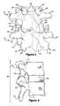
- FIG. 3is a posterior perspective view of a vertebral lumbar facet joint
- FIGS. 5A-5Cillustrate a facet implant alone and in conjunction with a facet joint in a posterior perspective view
- FIG. 6is a flow chart generally illustrating a method for providing articulating surfaces for facet joint articular facets
- FIG. 7is an illustration of a rasp being used to prepare an articulating surface
- FIGS. 8-10are illustrations of different types of rasps.
- FIG. 11is an illustration of an aiming device for use in positioning a translaminar screw.
- the spinal column 10is comprised of a series of thirty-three stacked vertebrae divided into five regions.
- the cervical regionincludes seven vertebrae, known as C1-C7.
- the thoracic regionincludes twelve vertebrae, known as T1-T12.
- the lumbar regioncontains five vertebrae, known as L1-L5.
- the sacral regionis comprised of five vertebrae, known as S1-S5.
- the coccygeal regioncontains four vertebrae 12 , known as Co1-Co4.
- Each vertebra 12includes a vertebral body 14 .
- Two short bones, the pedicles 16extend backward from each side of the vertebral body 14 to form a vertebral arch 18 .
- the vertebral arch 18flares out into broad plates of bone known as the laminae 20 .
- the laminae 20fuse with each other to form a spinous process 22 .
- the spinuous process 22provides muscle and ligament attachment.
- the transition from the pedicles 16 to the laminae 20is interrupted by a series of processes.
- Two transverse processes 24thrust out laterally on each side from the junction of the pedicle 16 and the lamina 20 .
- the transverse processes 24serve as guides for the attachment of muscles to the vertebrae 12 .
- Four articular processes, two superior 26 and two inferior 28also rise from the junctions of the pedicles 16 and the laminae 20 .
- the superior articular processes 26are oval plates of bone rising upward on each side from the union of the pedicle 16 with the lamina 20 .
- the inferior processes 28are oval plates of bone jutting downward on each side.
- the superior and inferior articular processes 26 and 28respectively, each have a natural bony structure known as a facet.
- the superior articular facet 30faces upward, while the inferior articular facet 32 faces downward.
- the superior articular facet 30 and the inferior articular facet 32have articulating surfaces 38 and 40 , respectively
- the superior articular facet 30 and inferior articular facet 32interlock.
- the interlocked vertebraeform a facet joint 36 , also known as a zygapophysial joint.
- An intervertebral disc 34 between each pair of vertebrae 12permits gliding movement between vertebrae 12 .
- the structure and alignment of the vertebrae 12permit a range of movement of the vertebrae 12 relative to each other.
- the facet joint 36is composed of a superior half and an inferior half.
- the superior halfis formed by the vertebral level below the intervertebral disc 34
- the inferior halfis formed by the vertebral level above the intervertebral disc 34 .
- the superior portion of the jointis formed by bony structure on the L-5 vertebra (e.g., a superior articular surface and supporting bone on the L-5 vertebra)
- the inferior portion of the jointis formed by bony structure on the L-4 vertebra (e.g., an inferior articular surface and supporting bone on the L-4 vertebra).
- the exemplary facet implant 100generally has a superior implant 102 and an inferior implant 104 .
- the superior implant 102generally has an articulating surface 108 and a fixation surface 110 .
- the inferior implant 104generally has an articulating surface 112 and a fixation surface 114 .
- the superior implant 102is configured for placement on superior articular facet 30 .
- the superior implant 102may be fixed to the superior articulating surface 38 using cemented and/or cementless fixation techniques.
- the superior implant 102has an articulating surface 108 and a fixation surface 110 and is configured for placement on a specifically prepared superior articulating surface 38 .
- the articulating surface 108may be generally curved and may be configured to interact with an articulating surface 112 of the inferior implant 104 .
- the superior implant 102may have a surface fixation mechanism for fixing the superior implant 102 , such as by fixing the fixation surface 110 , to the superior articulating surface 38 .
- the surface fixation mechanismmay be any fixation mechanism known in the art, such as: one or more pegs, one or more pips, ridges or grooves, one or more screws.
- the surface fixation mechanismincludes a plurality of ridges, grouped in regions such that the ridges in different regions are oriented in different directions.
- the surface fixation mechanismmay include four regions on the fixation surface 110 where each of the four regions has ridges oriented in a different direction. The various orientations of the ridges prevent the superior implant 102 from moving in different directions with respect to the superior articulating surface 38 .
- the articulating surface 108 in one exemplary embodimentis generally configured to articulate or interact with the articulating surface 112 of the inferior implant 104 .
- the articulating surface 108 of the superior implant 102may be generally curved.
- the superior implant 102 articulating surface 108may be configured such that it acts as a “female” surface wherein it is concave or configured to accept a “male” articulating surface 112 of an inferior implant 104 .
- the superior implant 102 articulating surface 108may also be configured such that it acts as a “male” surface wherein it is convex or configured to be accepted by “female” articulating surface 112 of an inferior implant 104 .
- the superior implant 102may be composed of any material commonly used in the art for articulating medical implants. Such materials include, but are not limited to, cobalt-chromium alloys, ceramics (alumina ceramic, zirconia ceramic, yttria zirconia ceramic, etc.), titanium, ultra high molecular weight polyethylene (UHMWPE), pyrolytic carbon, titanium/aluminum/vanadium (Ti/Al/V) alloys, Tantalum, Carbon composite materials and combinations thereof.
- the superior implant 102may be generally composed of titanium, but have a UHMWPE articulating surface. Some materials are more appropriate for articulating surfaces and some more appropriate for fixation surfaces, but any materials known in the art for use with articulating and fixation surfaces can be used in the present invention. Such materials are commonly used in joint arthroplasty and the like.
- the superior implant 102may be from about 2 mm thick to about 15 mm thick. In an exemplary embodiment, the thickness (T s ) of the superior implant 102 ranges from about 6 mm to about 10 mm. In another exemplary embodiment, the thickness (T s ) of the superior implant 102 ranges from about 3 mm to about 5 mm.
- the inferior implant 104is configured for placement on inferior articular facet 32 .
- the inferior implant 104may be fixed to the inferior articulating surface 40 using cemented and/or cementless fixation techniques.
- the inferior implant 104has an articulating surface 112 and a fixation surface 114 and is configured for placement on a specifically prepared inferior articulating surface 40 .
- the articulating surface 112may be generally convex and may be configured to interact with an articulating surface 108 of the superior implant 102 .
- the fixation surface 114 of the inferior implant 104is configured to interact only with the inferior articulating surface 40 and does not interact directly with any other aspect of the inferior articular facet 32 , the inferior articular process 28 , or even the facet joint 36 .
- the fixation surface 114 of the inferior implant 104may be generally flat or generally curved for improved interaction with the inferior articulating surface 40 .
- the articulating surface 112 of the inferior implant 104in one exemplary embodiment is generally configured to articulate or interact with the articulating surface 108 of the superior implant 102 . Accordingly, the articulating surface 112 of the inferior implant 104 may be generally convex.
- the inferior implant 104 articulating surface 112may be configured such that it acts as a “male” surface wherein it is convex or configured to be accepted by a “female” articulating surface 108 of a superior implant 102 .
- the inferior implant 104 articulating surface 112may also be configured such that it acts as a “female” surface wherein it is configured to accept a “male” articulating surface 108 of a superior implant 102 .
- the inferior implant 104may be composed of any material commonly used in the art for articulating medical implants. Such materials include, but are not limited to, cobalt-chromium alloys, ceramics (alumina ceramic, zirconia ceramic, yttria zirconia ceramic, etc.), titanium, ultra high molecular weight polyethylene (UHMWPE), pyrolytic carbon, titanium/aluminum/vanadium (Ti/Al/V) alloys, and combinations thereof.
- the inferior implant 104may be generally composed of a ceramic material or a cobalt-chromium alloy. Some materials are more appropriate for articulating surfaces and some more appropriate for fixation surfaces, but any materials known in the art for use with articulating and fixation surfaces can be used in the present invention. Such materials are commonly used in joint arthroplasty and the like.
- the inferior implant 104may be from about 2 mm thick to about 15 mm thick. In an exemplary embodiment, the thickness (T i ) of the inferior implant 104 ranges from about 6 mm to about 12 mm. In another exemplary embodiment, the thickness (T i ) of the inferior implant 104 ranges from about 3 mm to about 5 mm.
- One exemplary embodiment of the present inventionincludes a translaminar fixation mechanism 106 configured to interact with the inferior implant 104 .
- the translaminar fixation mechanism 106secures the inferior implant 104 to the inferior articular facet 32 .
- the translaminar fixation mechanismmay be any fixation mechanism known in the art, such as a translaminar screw.
- the translaminar fixation mechanismmay be made from any material known in art for medical fixation devices.
- the translaminar fixation mechanismmay be made from titanium, titanium/aluminum/vanadium (Ti/Al/V) alloys, Tantalum, CrCo, ceramic, carbon or carbon composite materials.
- FIG. 6there is provided a flow diagram generally illustrating a method for providing articulating surfaces for facet joint articular facets.
- the overall flowbegins at process block 602 wherein a space is created between the superior articular facet 30 and the inferior articular facet 32 .
- a spaceis created between the superior articular facet 30 and the inferior articular facet 32 .
- the effected levelmay be exposed through use of any appropriate procedure, such as a modified “Wiltse” approach.
- the creation of the space at process block 602may be accomplished by using a curette or similar device and by removing the cartilaginous surfaces of the facet joint 36 .
- Flowprogresses to process block 604 wherein a rasp is used to prepare the articulating surface 40 of the inferior articular facet 32 for an inferior implant 104 .
- Progressionthen continues to process block 606 wherein a rasp is used to prepare the articulating surface 38 of the superior articular facet 30 for a superior implant 102 .
- Each of the rasps of process blocks 604 and 606may be either a single shaft rasp or a double action rasp, such as those illustrated in FIGS. 8-10 and described in detail herein.
- the process of preparing the articulating surfaces 38 and 40 of the articular facets 28 and 30may involve using multiple rasps of increasing thickness while widening the space created in process block 602 .
- a 2 mm raspmay initially be used, then a 4 mm rasp, then a 6 mm rasp, then an 8 mm rasp, etc., until a desired result is achieved.
- the rasps of process blocks 604 and 606may be the same rasp.
- a single raspcan be used to prepare the articulating surfaces 38 and 40 concurrently.
- the articulating surfaces 38 and 40may be prepared such that a bleeding bone bed is created to facilitate bone ingrowth for the superior implant 102 and inferior implant 104 .
- the working end of the toolmay be positioned inside the space created in process block 602 .
- the raspmay then be moved from an anterior to a posterior position inside the facet joint 36 in order to effect a clean and uniform resection of the created space in the shape and dimension of both implants.
- the articulating surface 38is prepared such that its shape and dimension resembles the superior implant 102
- the articulating surface 40is prepared such that its shape and dimension resembles the inferior implant 104 .
- the anterior/posterior movement of the raspmay be continued until the rasp is too small for the space created.
- the raspmay be too small when the space created is so wide that the rasp cannot prepare both the articulating surfaces 38 and 40 concurrently.
- a larger (thicker) raspmay then be used.
- Increasingly larger raspsmay be used until the created space is increased such that it ranges from about 4 mm to about 15 mm.
- the raspsare designed to cut only when moving in a posterior direction to help prevent injury during the resurfacing process.
- an aiming devicesuch as the one illustrated in FIG. 11 may be used.
- the aiming devicecan be used to position a drill for creating a translaminar hole for the translaminar screw 106 .
- a drillcan then be used to create the hole, which may have a diameter of about 2 mm, depending on the diameter of the translaminar screw 106 .
- the translaminar screw 106can be introduced into the hole and then used to secure the inferior implant 104 to the inferior articular facet 32 .
- the steps of process blocks 602 , 604 , 606 , 608 and 610are then repeated on the contralateral side.
- fixation appendages 910may be configured for interaction with the lamina 20 or with a cephalad position of the superior facet 26 .
- squeezing the handles 902 of the rasp 900causes the head 906 to move in a cephalad position and releasing the handles 902 causes the head 906 to move in a caudad direction.
Landscapes
- Health & Medical Sciences (AREA)
- Orthopedic Medicine & Surgery (AREA)
- Life Sciences & Earth Sciences (AREA)
- Engineering & Computer Science (AREA)
- Biomedical Technology (AREA)
- Surgery (AREA)
- General Health & Medical Sciences (AREA)
- Oral & Maxillofacial Surgery (AREA)
- Veterinary Medicine (AREA)
- Heart & Thoracic Surgery (AREA)
- Public Health (AREA)
- Animal Behavior & Ethology (AREA)
- Dentistry (AREA)
- Nuclear Medicine, Radiotherapy & Molecular Imaging (AREA)
- Medical Informatics (AREA)
- Molecular Biology (AREA)
- Vascular Medicine (AREA)
- Transplantation (AREA)
- Cardiology (AREA)
- Neurology (AREA)
- Prostheses (AREA)
Abstract
Description
Claims (42)
Priority Applications (6)
| Application Number | Priority Date | Filing Date | Title |
|---|---|---|---|
| US10/651,871US9254137B2 (en) | 2003-08-29 | 2003-08-29 | Facet implant |
| JP2006524924AJP4567682B2 (en) | 2003-08-29 | 2004-08-27 | Small joint surface implant |
| PCT/US2004/028094WO2005020850A2 (en) | 2003-08-29 | 2004-08-27 | Facet implant |
| EP04782550AEP1659954A4 (en) | 2003-08-29 | 2004-08-27 | Facet implant |
| US11/684,187US7988712B2 (en) | 2003-08-29 | 2007-03-09 | Method for resurfacing a lumbar articular facet |
| US13/165,958US20110251647A1 (en) | 2003-08-29 | 2011-06-22 | Method for resurfacing a lumbar articular facet |
Applications Claiming Priority (1)
| Application Number | Priority Date | Filing Date | Title |
|---|---|---|---|
| US10/651,871US9254137B2 (en) | 2003-08-29 | 2003-08-29 | Facet implant |
Related Child Applications (1)
| Application Number | Title | Priority Date | Filing Date |
|---|---|---|---|
| US11/684,187DivisionUS7988712B2 (en) | 2003-08-29 | 2007-03-09 | Method for resurfacing a lumbar articular facet |
Publications (2)
| Publication Number | Publication Date |
|---|---|
| US20050049705A1 US20050049705A1 (en) | 2005-03-03 |
| US9254137B2true US9254137B2 (en) | 2016-02-09 |
Family
ID=34217496
Family Applications (3)
| Application Number | Title | Priority Date | Filing Date |
|---|---|---|---|
| US10/651,871Active2030-03-25US9254137B2 (en) | 2003-08-29 | 2003-08-29 | Facet implant |
| US11/684,187Expired - Fee RelatedUS7988712B2 (en) | 2003-08-29 | 2007-03-09 | Method for resurfacing a lumbar articular facet |
| US13/165,958AbandonedUS20110251647A1 (en) | 2003-08-29 | 2011-06-22 | Method for resurfacing a lumbar articular facet |
Family Applications After (2)
| Application Number | Title | Priority Date | Filing Date |
|---|---|---|---|
| US11/684,187Expired - Fee RelatedUS7988712B2 (en) | 2003-08-29 | 2007-03-09 | Method for resurfacing a lumbar articular facet |
| US13/165,958AbandonedUS20110251647A1 (en) | 2003-08-29 | 2011-06-22 | Method for resurfacing a lumbar articular facet |
Country Status (4)
| Country | Link |
|---|---|
| US (3) | US9254137B2 (en) |
| EP (1) | EP1659954A4 (en) |
| JP (1) | JP4567682B2 (en) |
| WO (1) | WO2005020850A2 (en) |
Families Citing this family (217)
| Publication number | Priority date | Publication date | Assignee | Title |
|---|---|---|---|---|
| US8556983B2 (en) | 2001-05-25 | 2013-10-15 | Conformis, Inc. | Patient-adapted and improved orthopedic implants, designs and related tools |
| US8480754B2 (en) | 2001-05-25 | 2013-07-09 | Conformis, Inc. | Patient-adapted and improved articular implants, designs and related guide tools |
| US8882847B2 (en) | 2001-05-25 | 2014-11-11 | Conformis, Inc. | Patient selectable knee joint arthroplasty devices |
| US8545569B2 (en) | 2001-05-25 | 2013-10-01 | Conformis, Inc. | Patient selectable knee arthroplasty devices |
| US8617242B2 (en) | 2001-05-25 | 2013-12-31 | Conformis, Inc. | Implant device and method for manufacture |
| US9603711B2 (en) | 2001-05-25 | 2017-03-28 | Conformis, Inc. | Patient-adapted and improved articular implants, designs and related guide tools |
| US20030055502A1 (en) | 2001-05-25 | 2003-03-20 | Philipp Lang | Methods and compositions for articular resurfacing |
| WO2000035346A2 (en) | 1998-09-14 | 2000-06-22 | Stanford University | Assessing the condition of a joint and preventing damage |
| US7239908B1 (en) | 1998-09-14 | 2007-07-03 | The Board Of Trustees Of The Leland Stanford Junior University | Assessing the condition of a joint and devising treatment |
| ATE285207T1 (en)* | 1999-10-22 | 2005-01-15 | Archus Orthopedics Inc | FACET ARTHROPLASTY DEVICES |
| US6811567B2 (en)* | 1999-10-22 | 2004-11-02 | Archus Orthopedics Inc. | Facet arthroplasty devices and methods |
| US20050027361A1 (en)* | 1999-10-22 | 2005-02-03 | Reiley Mark A. | Facet arthroplasty devices and methods |
| US7674293B2 (en)* | 2004-04-22 | 2010-03-09 | Facet Solutions, Inc. | Crossbar spinal prosthesis having a modular design and related implantation methods |
| US6974478B2 (en)* | 1999-10-22 | 2005-12-13 | Archus Orthopedics, Inc. | Prostheses, systems and methods for replacement of natural facet joints with artificial facet joint surfaces |
| US8187303B2 (en)* | 2004-04-22 | 2012-05-29 | Gmedelaware 2 Llc | Anti-rotation fixation element for spinal prostheses |
| US7691145B2 (en)* | 1999-10-22 | 2010-04-06 | Facet Solutions, Inc. | Prostheses, systems and methods for replacement of natural facet joints with artificial facet joint surfaces |
| DE60136474D1 (en) | 2000-09-14 | 2008-12-18 | Univ R | ASSESSMENT OF THE CONDITION OF A JOINT AND LOSS OF CARTEL TISSUE |
| US20080177310A1 (en)* | 2000-10-20 | 2008-07-24 | Archus Orthopedics, Inc. | Facet arthroplasty devices and methods |
| US6579319B2 (en)* | 2000-11-29 | 2003-06-17 | Medicinelodge, Inc. | Facet joint replacement |
| US20020169507A1 (en) | 2000-12-14 | 2002-11-14 | David Malone | Interbody spine fusion cage |
| CA2437575C (en)* | 2001-02-16 | 2009-04-07 | Queen's University At Kingston | Method and device for treating abnormal curvature of the spine |
| JP2006505366A (en) | 2002-11-07 | 2006-02-16 | コンフォーミス・インコーポレイテッド | Method of determining meniscus size and shape and devised treatment |
| US20040230304A1 (en)* | 2003-05-14 | 2004-11-18 | Archus Orthopedics Inc. | Prostheses, tools and methods for replacement of natural facet joints with artifical facet joint surfaces |
| US20040230201A1 (en)* | 2003-05-14 | 2004-11-18 | Archus Orthopedics Inc. | Prostheses, tools and methods for replacement of natural facet joints with artifical facet joint surfaces |
| US7608104B2 (en)* | 2003-05-14 | 2009-10-27 | Archus Orthopedics, Inc. | Prostheses, tools and methods for replacement of natural facet joints with artifical facet joint surfaces |
| US7074238B2 (en)* | 2003-07-08 | 2006-07-11 | Archus Orthopedics, Inc. | Prostheses, tools and methods for replacement of natural facet joints with artificial facet joint surfaces |
| US7588590B2 (en) | 2003-12-10 | 2009-09-15 | Facet Solutions, Inc | Spinal facet implant with spherical implant apposition surface and bone bed and methods of use |
| US20050131406A1 (en)* | 2003-12-15 | 2005-06-16 | Archus Orthopedics, Inc. | Polyaxial adjustment of facet joint prostheses |
| US8012210B2 (en)* | 2004-01-16 | 2011-09-06 | Warsaw Orthopedic, Inc. | Implant frames for use with settable materials and related methods of use |
| US7846183B2 (en)* | 2004-02-06 | 2010-12-07 | Spinal Elements, Inc. | Vertebral facet joint prosthesis and method of fixation |
| US9451990B2 (en)* | 2004-02-17 | 2016-09-27 | Globus Medical, Inc. | Facet joint replacement instruments and methods |
| US8333789B2 (en) | 2007-01-10 | 2012-12-18 | Gmedelaware 2 Llc | Facet joint replacement |
| US8562649B2 (en) | 2004-02-17 | 2013-10-22 | Gmedelaware 2 Llc | System and method for multiple level facet joint arthroplasty and fusion |
| US7051451B2 (en)* | 2004-04-22 | 2006-05-30 | Archus Orthopedics, Inc. | Facet joint prosthesis measurement and implant tools |
| WO2006055186A2 (en)* | 2004-10-25 | 2006-05-26 | Archus Orthopedics, Inc. | Spinal prosthesis having a modular design |
| US7914556B2 (en)* | 2005-03-02 | 2011-03-29 | Gmedelaware 2 Llc | Arthroplasty revision system and method |
| US20080082171A1 (en)* | 2004-04-22 | 2008-04-03 | Kuiper Mark K | Crossbar spinal prosthesis having a modular design and systems for treating spinal pathologies |
| US7406775B2 (en)* | 2004-04-22 | 2008-08-05 | Archus Orthopedics, Inc. | Implantable orthopedic device component selection instrument and methods |
| US20070093833A1 (en)* | 2004-05-03 | 2007-04-26 | Kuiper Mark K | Crossbar spinal prosthesis having a modular design and related implantation methods |
| US7507242B2 (en) | 2004-06-02 | 2009-03-24 | Facet Solutions | Surgical measurement and resection framework |
| US9504583B2 (en) | 2004-06-10 | 2016-11-29 | Spinal Elements, Inc. | Implant and method for facet immobilization |
| US7658753B2 (en)* | 2004-08-03 | 2010-02-09 | K Spine, Inc. | Device and method for correcting a spinal deformity |
| WO2006017641A2 (en)* | 2004-08-03 | 2006-02-16 | Vertech Innovations, L.L.C. | Spinous process reinforcement device and method |
| US8114158B2 (en)* | 2004-08-03 | 2012-02-14 | Kspine, Inc. | Facet device and method |
| US8414648B2 (en)* | 2004-08-09 | 2013-04-09 | Si-Bone Inc. | Apparatus, systems, and methods for achieving trans-iliac lumbar fusion |
| US8444693B2 (en)* | 2004-08-09 | 2013-05-21 | Si-Bone Inc. | Apparatus, systems, and methods for achieving lumbar facet fusion |
| US9662158B2 (en) | 2004-08-09 | 2017-05-30 | Si-Bone Inc. | Systems and methods for the fixation or fusion of bone at or near a sacroiliac joint |
| US9949843B2 (en) | 2004-08-09 | 2018-04-24 | Si-Bone Inc. | Apparatus, systems, and methods for the fixation or fusion of bone |
| US8425570B2 (en) | 2004-08-09 | 2013-04-23 | Si-Bone Inc. | Apparatus, systems, and methods for achieving anterior lumbar interbody fusion |
| US8388667B2 (en) | 2004-08-09 | 2013-03-05 | Si-Bone, Inc. | Systems and methods for the fixation or fusion of bone using compressive implants |
| US20070156241A1 (en) | 2004-08-09 | 2007-07-05 | Reiley Mark A | Systems and methods for the fixation or fusion of bone |
| US8470004B2 (en) | 2004-08-09 | 2013-06-25 | Si-Bone Inc. | Apparatus, systems, and methods for stabilizing a spondylolisthesis |
| US20180228621A1 (en) | 2004-08-09 | 2018-08-16 | Mark A. Reiley | Apparatus, systems, and methods for the fixation or fusion of bone |
| US20060036251A1 (en) | 2004-08-09 | 2006-02-16 | Reiley Mark A | Systems and methods for the fixation or fusion of bone |
| US7846184B2 (en)* | 2004-08-13 | 2010-12-07 | Sasso Ricardo C | Replacement facet joint and method |
| US20060041311A1 (en)* | 2004-08-18 | 2006-02-23 | Mcleer Thomas J | Devices and methods for treating facet joints |
| AU2005277363A1 (en)* | 2004-08-18 | 2006-03-02 | Fsi Acquisition Sub, Llc | Adjacent level facet arthroplasty devices, spine stabilization systems, and methods |
| US20060079895A1 (en)* | 2004-09-30 | 2006-04-13 | Mcleer Thomas J | Methods and devices for improved bonding of devices to bone |
| US20060085075A1 (en)* | 2004-10-04 | 2006-04-20 | Archus Orthopedics, Inc. | Polymeric joint complex and methods of use |
| US7935134B2 (en) | 2004-10-20 | 2011-05-03 | Exactech, Inc. | Systems and methods for stabilization of bone structures |
| US8226690B2 (en)* | 2005-07-22 | 2012-07-24 | The Board Of Trustees Of The Leland Stanford Junior University | Systems and methods for stabilization of bone structures |
| US8025680B2 (en)* | 2004-10-20 | 2011-09-27 | Exactech, Inc. | Systems and methods for posterior dynamic stabilization of the spine |
| US20070239159A1 (en)* | 2005-07-22 | 2007-10-11 | Vertiflex, Inc. | Systems and methods for stabilization of bone structures |
| US8267969B2 (en) | 2004-10-20 | 2012-09-18 | Exactech, Inc. | Screw systems and methods for use in stabilization of bone structures |
| US8162985B2 (en)* | 2004-10-20 | 2012-04-24 | The Board Of Trustees Of The Leland Stanford Junior University | Systems and methods for posterior dynamic stabilization of the spine |
| US8021392B2 (en)* | 2004-11-22 | 2011-09-20 | Minsurg International, Inc. | Methods and surgical kits for minimally-invasive facet joint fusion |
| US20060111779A1 (en)* | 2004-11-22 | 2006-05-25 | Orthopedic Development Corporation, A Florida Corporation | Minimally invasive facet joint fusion |
| WO2006058221A2 (en) | 2004-11-24 | 2006-06-01 | Abdou Samy M | Devices and methods for inter-vertebral orthopedic device placement |
| US20070016196A1 (en)* | 2005-05-10 | 2007-01-18 | Winslow Charles J | Inter-cervical facet implant with implantation tool |
| US8066749B2 (en)* | 2004-12-13 | 2011-11-29 | Warsaw Orthopedic, Inc. | Implant for stabilizing a bone graft during spinal fusion |
| US7776090B2 (en)* | 2004-12-13 | 2010-08-17 | Warsaw Orthopedic, Inc. | Inter-cervical facet implant and method |
| US7763050B2 (en) | 2004-12-13 | 2010-07-27 | Warsaw Orthopedic, Inc. | Inter-cervical facet implant with locking screw and method |
| US8128660B2 (en)* | 2004-12-13 | 2012-03-06 | Kyphon Sarl | Inter-cervical facet joint implant with locking screw system |
| US8172877B2 (en)* | 2004-12-13 | 2012-05-08 | Kyphon Sarl | Inter-cervical facet implant with surface enhancements |
| US8029540B2 (en) | 2005-05-10 | 2011-10-04 | Kyphon Sarl | Inter-cervical facet implant with implantation tool |
| US8118838B2 (en)* | 2004-12-13 | 2012-02-21 | Kyphon Sarl | Inter-cervical facet implant with multiple direction articulation joint and method for implanting |
| US20060200156A1 (en)* | 2005-01-05 | 2006-09-07 | Jamal Taha | Spinal docking system, spinal docking device, and methods of spinal stabilization |
| US20060190081A1 (en)* | 2005-02-09 | 2006-08-24 | Gary Kraus | Facet stabilization schemes |
| US8696707B2 (en)* | 2005-03-08 | 2014-04-15 | Zyga Technology, Inc. | Facet joint stabilization |
| US8496686B2 (en) | 2005-03-22 | 2013-07-30 | Gmedelaware 2 Llc | Minimally invasive spine restoration systems, devices, methods and kits |
| WO2006102443A2 (en)* | 2005-03-22 | 2006-09-28 | Archus Orthopedics, Inc. | Minimally invasive spine restoration systems, devices, methods and kits |
| US20060276801A1 (en)* | 2005-04-04 | 2006-12-07 | Yerby Scott A | Inter-cervical facet implant distraction tool |
| US20060241758A1 (en)* | 2005-04-20 | 2006-10-26 | Sdgi Holdings, Inc. | Facet spacers |
| US20060247769A1 (en)* | 2005-04-28 | 2006-11-02 | Sdgi Holdings, Inc. | Polycrystalline diamond compact surfaces on facet arthroplasty devices |
| US8523865B2 (en) | 2005-07-22 | 2013-09-03 | Exactech, Inc. | Tissue splitter |
| WO2007062079A2 (en)* | 2005-11-21 | 2007-05-31 | Philipp Lang | Devices and methods for treating facet joints, uncovertebral joints, costovertebral joints and other joints |
| US20070135814A1 (en)* | 2005-12-12 | 2007-06-14 | Sdgi Holdings, Inc. | Facet spacer |
| DE202005019487U1 (en)* | 2005-12-13 | 2007-04-26 | Deru Gmbh | Facet joint prosthesis |
| US8262696B2 (en)* | 2006-02-24 | 2012-09-11 | Medical Design, LLC | Multilevel facet/laminar fixation system |
| US8088148B2 (en)* | 2006-02-24 | 2012-01-03 | Medical Design, LLC | Dynamic/static facet fixation device and method |
| US20070233256A1 (en)* | 2006-03-15 | 2007-10-04 | Ohrt John A | Facet and disc arthroplasty system and method |
| US20070250166A1 (en)* | 2006-04-25 | 2007-10-25 | Sdgi Holdings, Inc. | Facet fusion implants and methods of use |
| US20080027543A1 (en)* | 2006-06-28 | 2008-01-31 | Sdgi Holdings, Inc. | Prosthesis and method for replacing degenerative vertebral portions |
| US8702755B2 (en)* | 2006-08-11 | 2014-04-22 | Gmedelaware 2 Llc | Angled washer polyaxial connection for dynamic spine prosthesis |
| US8096996B2 (en) | 2007-03-20 | 2012-01-17 | Exactech, Inc. | Rod reducer |
| US20080161929A1 (en) | 2006-12-29 | 2008-07-03 | Mccormack Bruce | Cervical distraction device |
| US8992533B2 (en)* | 2007-02-22 | 2015-03-31 | Spinal Elements, Inc. | Vertebral facet joint drill and method of use |
| EP2813190B1 (en) | 2007-02-22 | 2017-04-26 | Spinal Elements, Inc. | Vertebral facet joint drill |
| US20080255664A1 (en) | 2007-04-10 | 2008-10-16 | Mdesign International | Percutaneously deliverable orthopedic joint device |
| WO2008153732A1 (en)* | 2007-05-22 | 2008-12-18 | Vg Innovations, Llc | Method and apparatus for spinal facet fusion |
| EP2155086B1 (en) | 2007-06-06 | 2016-05-04 | K2M, Inc. | Medical device to correct deformity |
| US20110060366A1 (en)* | 2007-06-29 | 2011-03-10 | Stephen Heim | Facet Joint Implant and Related Methods |
| US8343189B2 (en)* | 2007-09-25 | 2013-01-01 | Zyga Technology, Inc. | Method and apparatus for facet joint stabilization |
| EP2923664B1 (en) | 2007-10-17 | 2019-01-02 | ARO Medical ApS | Systems and apparatuses for torsional stabilisation |
| US8109971B2 (en) | 2007-10-29 | 2012-02-07 | Horace Winston Hale | Orthopedic fixation mechanism |
| DE102007051783A1 (en) | 2007-10-30 | 2009-05-07 | Aesculap Ag | Facet joint implant |
| WO2009089367A2 (en) | 2008-01-09 | 2009-07-16 | Providence Medical Technology, Inc. | Methods and apparatus for accessing and treating the facet joint |
| WO2009111626A2 (en) | 2008-03-05 | 2009-09-11 | Conformis, Inc. | Implants for altering wear patterns of articular surfaces |
| CA2717610A1 (en)* | 2008-03-06 | 2009-09-11 | Synthes Usa, Llc | Facet interference screw |
| WO2009140294A1 (en) | 2008-05-12 | 2009-11-19 | Conformis, Inc. | Devices and methods for treatment of facet and other joints |
| CA2725811A1 (en) | 2008-06-06 | 2009-12-10 | Providence Medical Technology, Inc. | Facet joint implants and delivery tools |
| US8361152B2 (en) | 2008-06-06 | 2013-01-29 | Providence Medical Technology, Inc. | Facet joint implants and delivery tools |
| US11224521B2 (en) | 2008-06-06 | 2022-01-18 | Providence Medical Technology, Inc. | Cervical distraction/implant delivery device |
| USD612048S1 (en)* | 2008-06-06 | 2010-03-16 | Atlas Spine, Inc. | Rasp |
| US8267966B2 (en) | 2008-06-06 | 2012-09-18 | Providence Medical Technology, Inc. | Facet joint implants and delivery tools |
| USD612049S1 (en)* | 2008-06-06 | 2010-03-16 | Atlas Spine, Inc. | Delaminator |
| US9381049B2 (en) | 2008-06-06 | 2016-07-05 | Providence Medical Technology, Inc. | Composite spinal facet implant with textured surfaces |
| US9333086B2 (en) | 2008-06-06 | 2016-05-10 | Providence Medical Technology, Inc. | Spinal facet cage implant |
| EP2361046B1 (en) | 2008-06-06 | 2019-04-24 | Providence Medical Technology, Inc. | Cervical distraction/implant delivery device |
| USD612050S1 (en)* | 2008-06-13 | 2010-03-16 | Atlas Spine, Inc. | Rectangular rasp |
| EP2339985A4 (en)* | 2008-09-12 | 2013-07-03 | Articulinx Inc | Tether-based orthopedic joint device delivery methods |
| US20100191286A1 (en)* | 2008-10-03 | 2010-07-29 | Butler Jesse P | Facet compression system and related surgical methods |
| US8828058B2 (en) | 2008-11-11 | 2014-09-09 | Kspine, Inc. | Growth directed vertebral fixation system with distractible connector(s) and apical control |
| WO2010065277A1 (en)* | 2008-11-25 | 2010-06-10 | Synthes Usa, Llc | Visco-elastic facet joint implant |
| WO2010099231A2 (en) | 2009-02-24 | 2010-09-02 | Conformis, Inc. | Automated systems for manufacturing patient-specific orthopedic implants and instrumentation |
| US20100234905A1 (en)* | 2009-03-13 | 2010-09-16 | John Sledge | Facet joint resurfacing implant and associated surgical methods |
| US8357182B2 (en)* | 2009-03-26 | 2013-01-22 | Kspine, Inc. | Alignment system with longitudinal support features |
| US20100312343A1 (en)* | 2009-06-04 | 2010-12-09 | Linares Medical Devices, Llc | Tip support insert for application to left/right articular processes to minimize abrasion between vertebrae and to maintain proper angle/lift for reducing nerve compression |
| US8394125B2 (en) | 2009-07-24 | 2013-03-12 | Zyga Technology, Inc. | Systems and methods for facet joint treatment |
| JP2013504389A (en) | 2009-09-11 | 2013-02-07 | アーティキュリンクス, インコーポレイテッド | Disc-shaped orthopedic device |
| US9168071B2 (en) | 2009-09-15 | 2015-10-27 | K2M, Inc. | Growth modulation system |
| US8231661B2 (en)* | 2009-09-30 | 2012-07-31 | Warsaw Orthopedic | Systems and methods for minimally invasive facet fusion |
| US9078701B2 (en)* | 2009-11-09 | 2015-07-14 | Centinel Spine, Inc. | System and method for stabilizing a posterior fusion over motion segments |
| US8764806B2 (en) | 2009-12-07 | 2014-07-01 | Samy Abdou | Devices and methods for minimally invasive spinal stabilization and instrumentation |
| CA2782137A1 (en) | 2009-12-11 | 2011-06-16 | Conformis, Inc. | Patient-specific and patient-engineered orthopedic implants |
| US8663293B2 (en) | 2010-06-15 | 2014-03-04 | Zyga Technology, Inc. | Systems and methods for facet joint treatment |
| US9233006B2 (en) | 2010-06-15 | 2016-01-12 | Zyga Technology, Inc. | Systems and methods for facet joint treatment |
| US8986355B2 (en) | 2010-07-09 | 2015-03-24 | DePuy Synthes Products, LLC | Facet fusion implant |
| US8425611B2 (en) | 2010-10-26 | 2013-04-23 | Warsaw Orthopedic, Inc. | Expandable orthopedic implant system and method |
| US8409257B2 (en)* | 2010-11-10 | 2013-04-02 | Warsaw Othopedic, Inc. | Systems and methods for facet joint stabilization |
| WO2012112694A2 (en) | 2011-02-15 | 2012-08-23 | Conformis, Inc. | Medeling, analyzing and using anatomical data for patient-adapted implants. designs, tools and surgical procedures |
| US8740949B2 (en) | 2011-02-24 | 2014-06-03 | Spinal Elements, Inc. | Methods and apparatus for stabilizing bone |
| USD724733S1 (en) | 2011-02-24 | 2015-03-17 | Spinal Elements, Inc. | Interbody bone implant |
| US9271765B2 (en) | 2011-02-24 | 2016-03-01 | Spinal Elements, Inc. | Vertebral facet joint fusion implant and method for fusion |
| EP2685921B1 (en) | 2011-03-18 | 2019-03-13 | Raed M. Ali, M.D., Inc. | Transpedicular access to intervertebral spaces and related spinal fusion systems and methods |
| US9265620B2 (en) | 2011-03-18 | 2016-02-23 | Raed M. Ali, M.D., Inc. | Devices and methods for transpedicular stabilization of the spine |
| JP6158176B2 (en) | 2011-06-03 | 2017-07-05 | ケイツーエム インコーポレイテッドK2M,Inc. | Spine correction system |
| US9668783B2 (en)* | 2011-09-06 | 2017-06-06 | Atul Goel | Devices and method for treatment of spondylotic disease |
| US8845728B1 (en) | 2011-09-23 | 2014-09-30 | Samy Abdou | Spinal fixation devices and methods of use |
| USD739935S1 (en) | 2011-10-26 | 2015-09-29 | Spinal Elements, Inc. | Interbody bone implant |
| US8920472B2 (en) | 2011-11-16 | 2014-12-30 | Kspine, Inc. | Spinal correction and secondary stabilization |
| US9451987B2 (en) | 2011-11-16 | 2016-09-27 | K2M, Inc. | System and method for spinal correction |
| US9468469B2 (en) | 2011-11-16 | 2016-10-18 | K2M, Inc. | Transverse coupler adjuster spinal correction systems and methods |
| US9468468B2 (en) | 2011-11-16 | 2016-10-18 | K2M, Inc. | Transverse connector for spinal stabilization system |
| WO2014172632A2 (en) | 2011-11-16 | 2014-10-23 | Kspine, Inc. | Spinal correction and secondary stabilization |
| US20130226240A1 (en) | 2012-02-22 | 2013-08-29 | Samy Abdou | Spinous process fixation devices and methods of use |
| US10363140B2 (en) | 2012-03-09 | 2019-07-30 | Si-Bone Inc. | Systems, device, and methods for joint fusion |
| US8778026B2 (en) | 2012-03-09 | 2014-07-15 | Si-Bone Inc. | Artificial SI joint |
| US9044321B2 (en) | 2012-03-09 | 2015-06-02 | Si-Bone Inc. | Integrated implant |
| EP3818947B1 (en) | 2012-05-04 | 2023-08-30 | SI-Bone, Inc. | Fenestrated implant |
| US9198767B2 (en)* | 2012-08-28 | 2015-12-01 | Samy Abdou | Devices and methods for spinal stabilization and instrumentation |
| US9320617B2 (en) | 2012-10-22 | 2016-04-26 | Cogent Spine, LLC | Devices and methods for spinal stabilization and instrumentation |
| USD745156S1 (en) | 2012-10-23 | 2015-12-08 | Providence Medical Technology, Inc. | Spinal implant |
| USD732667S1 (en) | 2012-10-23 | 2015-06-23 | Providence Medical Technology, Inc. | Cage spinal implant |
| CA2887215A1 (en) | 2012-11-15 | 2014-05-22 | Zyga Technology, Inc. | Systems and methods for facet joint treatment |
| US8998968B1 (en) | 2012-11-28 | 2015-04-07 | Choice Spine, Lp | Facet screw system |
| US9820784B2 (en) | 2013-03-14 | 2017-11-21 | Spinal Elements, Inc. | Apparatus for spinal fixation and methods of use |
| US9861495B2 (en) | 2013-03-14 | 2018-01-09 | Raed M. Ali, M.D., Inc. | Lateral interbody fusion devices, systems and methods |
| US9421044B2 (en) | 2013-03-14 | 2016-08-23 | Spinal Elements, Inc. | Apparatus for bone stabilization and distraction and methods of use |
| US10687962B2 (en) | 2013-03-14 | 2020-06-23 | Raed M. Ali, M.D., Inc. | Interbody fusion devices, systems and methods |
| US9730737B2 (en)* | 2013-03-14 | 2017-08-15 | Atlas Spine, Inc. | Facet fixation with anchor wire |
| USD765853S1 (en) | 2013-03-14 | 2016-09-06 | Spinal Elements, Inc. | Flexible elongate member with a portion configured to receive a bone anchor |
| WO2014145902A1 (en) | 2013-03-15 | 2014-09-18 | Si-Bone Inc. | Implants for spinal fixation or fusion |
| US9468471B2 (en) | 2013-09-17 | 2016-10-18 | K2M, Inc. | Transverse coupler adjuster spinal correction systems and methods |
| US9456855B2 (en) | 2013-09-27 | 2016-10-04 | Spinal Elements, Inc. | Method of placing an implant between bone portions |
| US9839450B2 (en) | 2013-09-27 | 2017-12-12 | Spinal Elements, Inc. | Device and method for reinforcement of a facet |
| US9839448B2 (en) | 2013-10-15 | 2017-12-12 | Si-Bone Inc. | Implant placement |
| US11147688B2 (en) | 2013-10-15 | 2021-10-19 | Si-Bone Inc. | Implant placement |
| AU2015267055B2 (en) | 2014-05-27 | 2020-04-02 | Christopher U. Phan | Lateral mass fixation implant |
| JP2017520357A (en) | 2014-05-28 | 2017-07-27 | プロビデンス メディカル テクノロジー インコーポレイテッド | Outer mass fixing system |
| US11478275B2 (en) | 2014-09-17 | 2022-10-25 | Spinal Elements, Inc. | Flexible fastening band connector |
| US10166033B2 (en) | 2014-09-18 | 2019-01-01 | Si-Bone Inc. | Implants for bone fixation or fusion |
| JP6542362B2 (en) | 2014-09-18 | 2019-07-10 | エスアイ−ボーン・インコーポレイテッドSi−Bone, Inc. | Matrix implant |
| AU2016212009C1 (en) | 2015-01-27 | 2021-02-25 | Spinal Elements, Inc. | Facet joint implant |
| US10376206B2 (en) | 2015-04-01 | 2019-08-13 | Si-Bone Inc. | Neuromonitoring systems and methods for bone fixation or fusion procedures |
| CN108289689A (en) | 2015-10-13 | 2018-07-17 | 普罗维登斯医疗技术公司 | Joint of vertebral column implantation material conveying device and system |
| USD841165S1 (en) | 2015-10-13 | 2019-02-19 | Providence Medical Technology, Inc. | Cervical cage |
| US10857003B1 (en) | 2015-10-14 | 2020-12-08 | Samy Abdou | Devices and methods for vertebral stabilization |
| RU2622365C1 (en)* | 2016-01-19 | 2017-06-14 | "ЦхМ" Сп. з о.о. | Facet stabiliser |
| WO2017172806A1 (en) | 2016-03-29 | 2017-10-05 | Sturm Christopher | Facet joint replacement device and methods of use |
| US20170367839A1 (en) | 2016-06-23 | 2017-12-28 | VGI Medical, LLC | Method and apparatus for spinal facet fusion |
| TW201806562A (en) | 2016-06-28 | 2018-03-01 | 普羅維登斯醫療科技公司 | Spinal implant and methods of using the same |
| USD887552S1 (en) | 2016-07-01 | 2020-06-16 | Providence Medical Technology, Inc. | Cervical cage |
| US10744000B1 (en) | 2016-10-25 | 2020-08-18 | Samy Abdou | Devices and methods for vertebral bone realignment |
| US10973648B1 (en) | 2016-10-25 | 2021-04-13 | Samy Abdou | Devices and methods for vertebral bone realignment |
| PL234077B1 (en) | 2017-04-21 | 2020-01-31 | Chm Spolka Z Ograniczona Odpowiedzialnoscia | System of implants of a facet joint |
| US11871968B2 (en) | 2017-05-19 | 2024-01-16 | Providence Medical Technology, Inc. | Spinal fixation access and delivery system |
| US11931269B2 (en)* | 2017-07-10 | 2024-03-19 | Xtant Medical, Inc. | Delivery systems for interspinous, interlaminar stabilization devices and methods of use |
| US11116519B2 (en) | 2017-09-26 | 2021-09-14 | Si-Bone Inc. | Systems and methods for decorticating the sacroiliac joint |
| US11648128B2 (en) | 2018-01-04 | 2023-05-16 | Providence Medical Technology, Inc. | Facet screw and delivery device |
| ES3011907T3 (en) | 2018-03-28 | 2025-04-08 | Si Bone Inc | Threaded implants for use across bone segments |
| WO2020061464A1 (en) | 2018-09-21 | 2020-03-26 | Providence Medical Technology, Inc. | Vertebral joint access and decortication devices and methods of using |
| US11179248B2 (en) | 2018-10-02 | 2021-11-23 | Samy Abdou | Devices and methods for spinal implantation |
| US11369419B2 (en) | 2019-02-14 | 2022-06-28 | Si-Bone Inc. | Implants for spinal fixation and or fusion |
| EP4613244A2 (en) | 2019-02-14 | 2025-09-10 | SI-Bone Inc. | Implants for spinal fixation and or fusion |
| USD933230S1 (en) | 2019-04-15 | 2021-10-12 | Providence Medical Technology, Inc. | Cervical cage |
| BR112021022695A2 (en) | 2019-05-22 | 2021-12-28 | Spinal Elements Inc | Bone tethering and bone tethering inserter |
| US11457959B2 (en) | 2019-05-22 | 2022-10-04 | Spinal Elements, Inc. | Bone tie and bone tie inserter |
| USD911525S1 (en) | 2019-06-21 | 2021-02-23 | Providence Medical Technology, Inc. | Spinal cage |
| JP7646654B2 (en) | 2019-11-21 | 2025-03-17 | エスアイ-ボーン・インコーポレイテッド | Rod coupling assembly for bone stabilization construct - Patent application |
| AU2020392121B2 (en) | 2019-11-27 | 2025-05-22 | Si-Bone, Inc. | Bone stabilizing implants and methods of placement across SI joints |
| EP4072452A4 (en) | 2019-12-09 | 2023-12-20 | SI-Bone, Inc. | Sacro-iliac joint stabilizing implants and methods of implantation |
| WO2021163313A1 (en) | 2020-02-14 | 2021-08-19 | Spinal Elements, Inc. | Bone tie methods |
| USD945621S1 (en) | 2020-02-27 | 2022-03-08 | Providence Medical Technology, Inc. | Spinal cage |
| EP4259015A4 (en) | 2020-12-09 | 2024-09-11 | SI-Bone, Inc. | SACROILIAC JOINT STABILIZATION IMPLANTS AND METHODS OF IMPLANTATION |
| US12369952B2 (en) | 2021-12-10 | 2025-07-29 | Spinal Elements, Inc. | Bone tie and portal |
| WO2025038769A1 (en) | 2023-08-15 | 2025-02-20 | Si-Bone Inc. | Pelvic stabilization implants, methods of use and manufacture |
Citations (44)
| Publication number | Priority date | Publication date | Assignee | Title |
|---|---|---|---|---|
| US3879767A (en) | 1972-01-26 | 1975-04-29 | Cutter Lab | Prosthesis for articulating body structures |
| US4001896A (en) | 1975-06-09 | 1977-01-11 | Zimmer, U.S.A. Inc. | Prosthetic joint for total knee replacement |
| US4085466A (en) | 1974-11-18 | 1978-04-25 | National Research Development Corporation | Prosthetic joint device |
| US4502161A (en) | 1981-09-21 | 1985-03-05 | Wall W H | Prosthetic meniscus for the repair of joints |
| US4714469A (en) | 1987-02-26 | 1987-12-22 | Pfizer Hospital Products Group, Inc. | Spinal implant |
| US4759766A (en)* | 1984-09-04 | 1988-07-26 | Humboldt-Universitaet Zu Berlin | Intervertebral disc endoprosthesis |
| US4772287A (en) | 1987-08-20 | 1988-09-20 | Cedar Surgical, Inc. | Prosthetic disc and method of implanting |
| US4773402A (en) | 1985-09-13 | 1988-09-27 | Isola Implants, Inc. | Dorsal transacral surgical implant |
| EP0322334A1 (en) | 1987-12-23 | 1989-06-28 | Cremascoli France | Prosthesis implanted between vertebral spinous processes |
| US4936848A (en) | 1989-09-22 | 1990-06-26 | Bagby George W | Implant for vertebrae |
| EP0392124A1 (en) | 1987-11-16 | 1990-10-17 | Francis Henri Bréard | Surgical implant for limiting the relative movement of vertebrae |
| US5000165A (en) | 1989-05-15 | 1991-03-19 | Watanabe Robert S | Lumbar spine rod fixation system |
| US5127912A (en) | 1990-10-05 | 1992-07-07 | R. Charles Ray | Sacral implant system |
| DE9304368U1 (en) | 1993-03-18 | 1993-05-13 | AAP GmbH & Co. Betriebs KG, 1000 Berlin | Spinal implant |
| WO1993014721A1 (en) | 1992-01-28 | 1993-08-05 | Salut, Ltd. | Sacral implant system |
| EP0610837A1 (en) | 1993-02-09 | 1994-08-17 | Acromed Corporation | Spine disc |
| US5360431A (en) | 1990-04-26 | 1994-11-01 | Cross Medical Products | Transpedicular screw system and method of use |
| US5527314A (en) | 1993-01-04 | 1996-06-18 | Danek Medical, Inc. | Spinal fixation system |
| US5571191A (en) | 1995-03-16 | 1996-11-05 | Fitz; William R. | Artificial facet joint |
| US5586989A (en) | 1995-01-27 | 1996-12-24 | Bray, Jr.; Robert | Microsurgical curette |
| US5591165A (en) | 1992-11-09 | 1997-01-07 | Sofamor, S.N.C. | Apparatus and method for spinal fixation and correction of spinal deformities |
| US5683466A (en)* | 1996-03-26 | 1997-11-04 | Vitale; Glenn C. | Joint surface replacement system |
| US5895428A (en)* | 1996-11-01 | 1999-04-20 | Berry; Don | Load bearing spinal joint implant |
| US6014588A (en) | 1998-04-07 | 2000-01-11 | Fitz; William R. | Facet joint pain relief method and apparatus |
| US6039763A (en)* | 1998-10-27 | 2000-03-21 | Disc Replacement Technologies, Inc. | Articulating spinal disc prosthesis |
| US6132464A (en) | 1994-06-24 | 2000-10-17 | Paulette Fairant | Vertebral joint facets prostheses |
| US20020019637A1 (en) | 1999-10-21 | 2002-02-14 | George Frey | Devices and techniques for a posterior lateral disc space approach |
| US6379386B1 (en)* | 1997-09-09 | 2002-04-30 | Stryker Technologies Corporation | Anatomic glenoid shoulder prosthesis together with methods and tools for implanting same |
| US6436101B1 (en) | 1999-10-13 | 2002-08-20 | James S. Hamada | Rasp for use in spine surgery |
| US20020123806A1 (en) | 1999-10-22 | 2002-09-05 | Total Facet Technologies, Inc. | Facet arthroplasty devices and methods |
| US20020151895A1 (en)* | 2001-02-16 | 2002-10-17 | Soboleski Donald A. | Method and device for treating scoliosis |
| US20030004572A1 (en) | 2001-03-02 | 2003-01-02 | Goble E. Marlowe | Method and apparatus for spine joint replacement |
| US20030028250A1 (en) | 1999-10-22 | 2003-02-06 | Archus Orthopedics, Inc. | Prostheses, systems and methods for replacement of natural facet joints with artifical facet joint surfaces |
| DE10135771A1 (en) | 2001-07-23 | 2003-02-20 | Aesculap Ag & Co Kg | Vertebral facet joint implant comprises at least one fixing element with surfaces which are in full areal contact with at least one facet |
| US6565605B2 (en) | 2000-12-13 | 2003-05-20 | Medicinelodge, Inc. | Multiple facet joint replacement |
| WO2003041618A2 (en) | 2001-11-15 | 2003-05-22 | Louis Rene | Posterior vertebral joint prosthesis |
| US6579319B2 (en) | 2000-11-29 | 2003-06-17 | Medicinelodge, Inc. | Facet joint replacement |
| US6610091B1 (en) | 1999-10-22 | 2003-08-26 | Archus Orthopedics Inc. | Facet arthroplasty devices and methods |
| US20030216669A1 (en) | 2001-05-25 | 2003-11-20 | Imaging Therapeutics, Inc. | Methods and compositions for articular repair |
| US20040024462A1 (en)* | 2002-04-12 | 2004-02-05 | Ferree Bret A. | Spacerless artificial disc replacements |
| US6706068B2 (en)* | 2002-04-23 | 2004-03-16 | Bret A. Ferree | Artificial disc replacements with natural kinematics |
| US20040176844A1 (en)* | 2003-03-06 | 2004-09-09 | Rafail Zubok | Cervical disc replacement |
| US6810567B2 (en) | 1997-05-20 | 2004-11-02 | Messer Griesheim Gmbh | Partial or complete utilization of a pressurized-gas cylinder known per se for compressed, liquefied or dissolved gases |
| US20050143818A1 (en)* | 2003-05-14 | 2005-06-30 | Hansen Yuan | Prostheses, tools and methods for replacement of natural facet joints with artifical facet joint surfaces |
Family Cites Families (19)
| Publication number | Priority date | Publication date | Assignee | Title |
|---|---|---|---|---|
| US36758A (en)* | 1862-10-21 | Improved car-coupling | ||
| US4436101A (en)* | 1983-03-28 | 1984-03-13 | William Seatts | Self-extinguishing cigar or cigarette |
| US4772402A (en)* | 1987-05-06 | 1988-09-20 | Love Ray B | Coolant processing system |
| US5527312A (en) | 1994-08-19 | 1996-06-18 | Salut, Ltd. | Facet screw anchor |
| US5707373A (en) | 1996-04-26 | 1998-01-13 | Ikonos Corporation | Bone fastener and instrument for insertion thereof |
| DE29724567U1 (en) | 1996-02-14 | 2003-01-16 | Walter Lorenz Surgical, Inc., Jacksonville, Fla. | Bone fixation device and instrument for inserting the bone fixation device |
| IES970323A2 (en)* | 1997-04-30 | 1998-06-03 | Eskina Developments Limited | Spinal osteosynthesis device for mechanically interconnecting two adjacent vertebrae, in particular lumbar vertebrae |
| US6113637A (en) | 1998-10-22 | 2000-09-05 | Sofamor Danek Holdings, Inc. | Artificial intervertebral joint permitting translational and rotational motion |
| FR2817461B1 (en)* | 2000-12-01 | 2003-08-15 | Henry Graf | INTERVERTEBRAL STABILIZATION DEVICE |
| US6669729B2 (en) | 2002-03-08 | 2003-12-30 | Kingsley Richard Chin | Apparatus and method for the replacement of posterior vertebral elements |
| US20050055096A1 (en) | 2002-12-31 | 2005-03-10 | Depuy Spine, Inc. | Functional spinal unit prosthetic |
| US7101398B2 (en)* | 2002-12-31 | 2006-09-05 | Depuy Acromed, Inc. | Prosthetic facet joint ligament |
| US20040230304A1 (en) | 2003-05-14 | 2004-11-18 | Archus Orthopedics Inc. | Prostheses, tools and methods for replacement of natural facet joints with artifical facet joint surfaces |
| US20040230201A1 (en) | 2003-05-14 | 2004-11-18 | Archus Orthopedics Inc. | Prostheses, tools and methods for replacement of natural facet joints with artifical facet joint surfaces |
| US7074238B2 (en) | 2003-07-08 | 2006-07-11 | Archus Orthopedics, Inc. | Prostheses, tools and methods for replacement of natural facet joints with artificial facet joint surfaces |
| WO2005009302A2 (en)* | 2003-07-17 | 2005-02-03 | Lee Casey K | Facet joint prosthesis |
| US7588590B2 (en) | 2003-12-10 | 2009-09-15 | Facet Solutions, Inc | Spinal facet implant with spherical implant apposition surface and bone bed and methods of use |
| WO2005079711A1 (en) | 2004-02-18 | 2005-09-01 | Boehm Frank H Jr | Facet joint prosthesis and method of replacing a facet joint |
| US7051451B2 (en) | 2004-04-22 | 2006-05-30 | Archus Orthopedics, Inc. | Facet joint prosthesis measurement and implant tools |
- 2003
- 2003-08-29USUS10/651,871patent/US9254137B2/enactiveActive
- 2004
- 2004-08-27JPJP2006524924Apatent/JP4567682B2/ennot_activeExpired - Fee Related
- 2004-08-27EPEP04782550Apatent/EP1659954A4/ennot_activeWithdrawn
- 2004-08-27WOPCT/US2004/028094patent/WO2005020850A2/enactiveSearch and Examination
- 2007
- 2007-03-09USUS11/684,187patent/US7988712B2/ennot_activeExpired - Fee Related
- 2011
- 2011-06-22USUS13/165,958patent/US20110251647A1/ennot_activeAbandoned
Patent Citations (48)
| Publication number | Priority date | Publication date | Assignee | Title |
|---|---|---|---|---|
| US3879767A (en) | 1972-01-26 | 1975-04-29 | Cutter Lab | Prosthesis for articulating body structures |
| US4085466A (en) | 1974-11-18 | 1978-04-25 | National Research Development Corporation | Prosthetic joint device |
| US4001896A (en) | 1975-06-09 | 1977-01-11 | Zimmer, U.S.A. Inc. | Prosthetic joint for total knee replacement |
| US4502161A (en) | 1981-09-21 | 1985-03-05 | Wall W H | Prosthetic meniscus for the repair of joints |
| US4502161B1 (en) | 1981-09-21 | 1989-07-25 | ||
| US4759766A (en)* | 1984-09-04 | 1988-07-26 | Humboldt-Universitaet Zu Berlin | Intervertebral disc endoprosthesis |
| US4773402A (en) | 1985-09-13 | 1988-09-27 | Isola Implants, Inc. | Dorsal transacral surgical implant |
| US4714469A (en) | 1987-02-26 | 1987-12-22 | Pfizer Hospital Products Group, Inc. | Spinal implant |
| US4904260A (en) | 1987-08-20 | 1990-02-27 | Cedar Surgical, Inc. | Prosthetic disc containing therapeutic material |
| US4772287A (en) | 1987-08-20 | 1988-09-20 | Cedar Surgical, Inc. | Prosthetic disc and method of implanting |
| EP0392124A1 (en) | 1987-11-16 | 1990-10-17 | Francis Henri Bréard | Surgical implant for limiting the relative movement of vertebrae |
| EP0322334A1 (en) | 1987-12-23 | 1989-06-28 | Cremascoli France | Prosthesis implanted between vertebral spinous processes |
| US5000165A (en) | 1989-05-15 | 1991-03-19 | Watanabe Robert S | Lumbar spine rod fixation system |
| US4936848A (en) | 1989-09-22 | 1990-06-26 | Bagby George W | Implant for vertebrae |
| US5360431A (en) | 1990-04-26 | 1994-11-01 | Cross Medical Products | Transpedicular screw system and method of use |
| US5127912A (en) | 1990-10-05 | 1992-07-07 | R. Charles Ray | Sacral implant system |
| WO1993014721A1 (en) | 1992-01-28 | 1993-08-05 | Salut, Ltd. | Sacral implant system |
| US5591165A (en) | 1992-11-09 | 1997-01-07 | Sofamor, S.N.C. | Apparatus and method for spinal fixation and correction of spinal deformities |
| US5527314A (en) | 1993-01-04 | 1996-06-18 | Danek Medical, Inc. | Spinal fixation system |
| EP0610837A1 (en) | 1993-02-09 | 1994-08-17 | Acromed Corporation | Spine disc |
| DE9304368U1 (en) | 1993-03-18 | 1993-05-13 | AAP GmbH & Co. Betriebs KG, 1000 Berlin | Spinal implant |
| US6132464A (en) | 1994-06-24 | 2000-10-17 | Paulette Fairant | Vertebral joint facets prostheses |
| US5586989A (en) | 1995-01-27 | 1996-12-24 | Bray, Jr.; Robert | Microsurgical curette |
| US5571191A (en) | 1995-03-16 | 1996-11-05 | Fitz; William R. | Artificial facet joint |
| USRE36758E (en) | 1995-03-16 | 2000-06-27 | Fitz; William R. | Artificial facet joint |
| US5683466A (en)* | 1996-03-26 | 1997-11-04 | Vitale; Glenn C. | Joint surface replacement system |
| US5895428A (en)* | 1996-11-01 | 1999-04-20 | Berry; Don | Load bearing spinal joint implant |
| US6810567B2 (en) | 1997-05-20 | 2004-11-02 | Messer Griesheim Gmbh | Partial or complete utilization of a pressurized-gas cylinder known per se for compressed, liquefied or dissolved gases |
| US6379386B1 (en)* | 1997-09-09 | 2002-04-30 | Stryker Technologies Corporation | Anatomic glenoid shoulder prosthesis together with methods and tools for implanting same |
| US6014588A (en) | 1998-04-07 | 2000-01-11 | Fitz; William R. | Facet joint pain relief method and apparatus |
| US6039763A (en)* | 1998-10-27 | 2000-03-21 | Disc Replacement Technologies, Inc. | Articulating spinal disc prosthesis |
| US6436101B1 (en) | 1999-10-13 | 2002-08-20 | James S. Hamada | Rasp for use in spine surgery |
| US20020019637A1 (en) | 1999-10-21 | 2002-02-14 | George Frey | Devices and techniques for a posterior lateral disc space approach |
| US20020123806A1 (en) | 1999-10-22 | 2002-09-05 | Total Facet Technologies, Inc. | Facet arthroplasty devices and methods |
| US6610091B1 (en) | 1999-10-22 | 2003-08-26 | Archus Orthopedics Inc. | Facet arthroplasty devices and methods |
| US20030028250A1 (en) | 1999-10-22 | 2003-02-06 | Archus Orthopedics, Inc. | Prostheses, systems and methods for replacement of natural facet joints with artifical facet joint surfaces |
| US6579319B2 (en) | 2000-11-29 | 2003-06-17 | Medicinelodge, Inc. | Facet joint replacement |
| US6565605B2 (en) | 2000-12-13 | 2003-05-20 | Medicinelodge, Inc. | Multiple facet joint replacement |
| US20020151895A1 (en)* | 2001-02-16 | 2002-10-17 | Soboleski Donald A. | Method and device for treating scoliosis |
| US20030004572A1 (en) | 2001-03-02 | 2003-01-02 | Goble E. Marlowe | Method and apparatus for spine joint replacement |
| US20030216669A1 (en) | 2001-05-25 | 2003-11-20 | Imaging Therapeutics, Inc. | Methods and compositions for articular repair |
| DE10135771A1 (en) | 2001-07-23 | 2003-02-20 | Aesculap Ag & Co Kg | Vertebral facet joint implant comprises at least one fixing element with surfaces which are in full areal contact with at least one facet |
| WO2003041618A2 (en) | 2001-11-15 | 2003-05-22 | Louis Rene | Posterior vertebral joint prosthesis |
| US20040024462A1 (en)* | 2002-04-12 | 2004-02-05 | Ferree Bret A. | Spacerless artificial disc replacements |
| US6706068B2 (en)* | 2002-04-23 | 2004-03-16 | Bret A. Ferree | Artificial disc replacements with natural kinematics |
| US20040176844A1 (en)* | 2003-03-06 | 2004-09-09 | Rafail Zubok | Cervical disc replacement |
| US6908484B2 (en)* | 2003-03-06 | 2005-06-21 | Spinecore, Inc. | Cervical disc replacement |
| US20050143818A1 (en)* | 2003-05-14 | 2005-06-30 | Hansen Yuan | Prostheses, tools and methods for replacement of natural facet joints with artifical facet joint surfaces |
Non-Patent Citations (12)
| Title |
|---|
| Based on a Supplemental Search Report corresponding European Application No. 04782550.0 completed May 19, 2010. |
| Chiu, J.C., Davis, G.W., Clifford, T., and Greenspan M. Translaminar Facet Screw Fixation [retreived on May 27, 2003]. Retrieved from the Internet:<http://www.spinecenter.com/papers/facet/facet.htm. |
| D. Grob et al., "Translaminar screw fixation in the lumbar spine; technique, indications, results", Apr. 6, 1998, Eur Spine J. (1998) 7:178-186. |
| Dudley, Hugh A.F., ed., Carter, David C., ed. and Russell, R.C.G., ed., "Spinal Injuries," Rod & Operative Surgery-Orthopaedics Part 1, London: Butterworth-Heinemann, 1991, p. 641. |
| Jan P.J. van Schaik and Bart van Pinxteren, Journal of Spinal Disorders, "Curvature of the Lower Lumbar Facet Joints: Variations at Different Levels and Relationship with Orientation," vol. 12, No. 4, pp. 341-347, 1999. |
| Jike Lu, M.D., Nabil A. Ebraheim, M.D., and Richard A. Yeasting, PhD, The American Journal of Orthopedics, "Translaminar Facet Screw Placement: an Anatomic Study," pp. 550-555, Aug. 1999. |
| John M Cavanaugh, A. Cuneyt Ozaktay, H. Toshihiko Yamashita, and Albert I. King, "Lumbar Facet Pain: Biomechanics Neuroanatomy and Neurophysiology," Survey Article, J. Biomechanics, vol. 29, No. 9, pp. 1117-1129, 1996. |
| Manohar M. Panjabi, PhD, Thomas Oxland, MASc, Koichiro Takata, M.D., Vijay Goel, PhD, Joanne Duranceau, M.S. and Martin Krag, M.D., "Articular Facets of the Human Spine, Quantitative Three-Dimensional Anatomy," Spine vol. 18, No. 10, pp. 1298-1310, 1993. |
| Nabil A. Ebraheim, M.D., Rongming Xu, M.D., Huhammad Ahmad, M.D. and Richard A. Yeasting, PhD, "The Quantitative Anatomy of the Thoracic Facet and the Posterior Projection of Its Inferior Facet," Spine vol. 22, No. 16, pp. 1811-1818, 1997. |
| Nabil A. Ebraheim, Rongming Xu, Eric Challgren, and Richard A. Yeasting, Journal of Spiral Disorders, "Quantitative Anatomy of the Cervical Facet and the Posterior Projection of Its Inferior Facet," vol. 10, No. 4, pp. 308-316, 1997. |
| Office Action for corresponding Japanese Application No. 2006-524924 completed Nov. 24, 2009. |
| Scott D. Boden, M.D., K. Daniel Riew, M.D., Ken Yamaguchi, M.D., Thomas P. Branch, M.D., Dieter Schellinger, M.D., and Sam W. Wiesel, Atlanta Georgia, "Orientation of the Lumbar Facet Joints: Association with Degenerative Disc Disease," The Journal of Bone and Joint Surgery, Inc., vol. 78-A, No. 3, Mar. 1996. |
Also Published As
| Publication number | Publication date |
|---|---|
| US7988712B2 (en) | 2011-08-02 |
| US20110251647A1 (en) | 2011-10-13 |
| JP2007503884A (en) | 2007-03-01 |
| WO2005020850A3 (en) | 2005-07-14 |
| US20050049705A1 (en) | 2005-03-03 |
| WO2005020850A2 (en) | 2005-03-10 |
| EP1659954A4 (en) | 2010-06-16 |
| JP4567682B2 (en) | 2010-10-20 |
| US20070149976A1 (en) | 2007-06-28 |
| EP1659954A2 (en) | 2006-05-31 |
| WO2005020850B1 (en) | 2005-09-29 |
Similar Documents
| Publication | Publication Date | Title |
|---|---|---|
| US9254137B2 (en) | Facet implant | |
| US7922766B2 (en) | Method for resurfacing a cervical articular facet | |
| US8109971B2 (en) | Orthopedic fixation mechanism | |
| US12295855B2 (en) | Interspinous implants | |
| EP1628600B1 (en) | Prostheses for replacement of natural facet joints with artificial facet joint surfaces | |
| US7691145B2 (en) | Prostheses, systems and methods for replacement of natural facet joints with artificial facet joint surfaces | |
| AU2003238834B2 (en) | Prostheses, systems and methods for replacement of natural facet joints with artificial facet joint surfaces | |
| US20040230201A1 (en) | Prostheses, tools and methods for replacement of natural facet joints with artifical facet joint surfaces | |
| US20100256761A1 (en) | Minimally invasive total spine implant |
Legal Events
| Date | Code | Title | Description |
|---|---|---|---|
| AS | Assignment | Owner name:GERRASPINE A.G., SWITZERLAND Free format text:ASSIGNMENT OF ASSIGNORS INTEREST;ASSIGNORS:HALE, HORACE WINSTON;GROB, DIETER;REEL/FRAME:015079/0440 Effective date:20030821 | |
| AS | Assignment | Owner name:GERRRASPINE A.G., SWITZERLAND Free format text:ASSIGNMENT OF ASSIGNORS INTEREST;ASSIGNOR:JOHNSON, MARK C.;REEL/FRAME:017916/0140 Effective date:20060711 | |
| AS | Assignment | Owner name:RECH AG, SWITZERLAND Free format text:ASSIGNMENT OF ASSIGNORS INTEREST;ASSIGNOR:GERRASPINE AG;REEL/FRAME:028740/0820 Effective date:20110718 Owner name:LANTERNA MEDICAL TECHNOLOGIES LTD, UNITED KINGDOM Free format text:ASSIGNMENT OF ASSIGNORS INTEREST;ASSIGNOR:RECH AG;REEL/FRAME:028741/0357 Effective date:20120125 | |
| STCF | Information on status: patent grant | Free format text:PATENTED CASE | |
| FEPP | Fee payment procedure | Free format text:MAINTENANCE FEE REMINDER MAILED (ORIGINAL EVENT CODE: REM.); ENTITY STATUS OF PATENT OWNER: SMALL ENTITY | |
| FEPP | Fee payment procedure | Free format text:SURCHARGE FOR LATE PAYMENT, SMALL ENTITY (ORIGINAL EVENT CODE: M2554); ENTITY STATUS OF PATENT OWNER: SMALL ENTITY | |
| MAFP | Maintenance fee payment | Free format text:PAYMENT OF MAINTENANCE FEE, 4TH YR, SMALL ENTITY (ORIGINAL EVENT CODE: M2551); ENTITY STATUS OF PATENT OWNER: SMALL ENTITY Year of fee payment:4 | |
| FEPP | Fee payment procedure | Free format text:MAINTENANCE FEE REMINDER MAILED (ORIGINAL EVENT CODE: REM.); ENTITY STATUS OF PATENT OWNER: SMALL ENTITY | |
| FEPP | Fee payment procedure | Free format text:7.5 YR SURCHARGE - LATE PMT W/IN 6 MO, SMALL ENTITY (ORIGINAL EVENT CODE: M2555); ENTITY STATUS OF PATENT OWNER: SMALL ENTITY | |
| MAFP | Maintenance fee payment | Free format text:PAYMENT OF MAINTENANCE FEE, 8TH YR, SMALL ENTITY (ORIGINAL EVENT CODE: M2552); ENTITY STATUS OF PATENT OWNER: SMALL ENTITY Year of fee payment:8 |