US9249645B2 - Apparatus for sealing off a part of a wall in a section drilled into an earth formation, and a method for applying the apparatus - Google Patents
Apparatus for sealing off a part of a wall in a section drilled into an earth formation, and a method for applying the apparatusDownload PDFInfo
- Publication number
- US9249645B2 US9249645B2US13/513,760US201013513760AUS9249645B2US 9249645 B2US9249645 B2US 9249645B2US 201013513760 AUS201013513760 AUS 201013513760AUS 9249645 B2US9249645 B2US 9249645B2
- Authority
- US
- United States
- Prior art keywords
- elongate members
- earth formation
- wall
- drilled
- section
- Prior art date
- Legal status (The legal status is an assumption and is not a legal conclusion. Google has not performed a legal analysis and makes no representation as to the accuracy of the status listed.)
- Active, expires
Links
- 230000015572biosynthetic processEffects0.000titleclaimsabstractdescription82
- 238000007789sealingMethods0.000titleclaimsabstractdescription47
- 238000000034methodMethods0.000titleclaimsabstractdescription12
- 239000012530fluidSubstances0.000claimsdescription18
- 238000004080punchingMethods0.000description3
- XLYOFNOQVPJJNP-UHFFFAOYSA-NwaterSubstancesOXLYOFNOQVPJJNP-UHFFFAOYSA-N0.000description3
- 238000002347injectionMethods0.000description2
- 239000007924injectionSubstances0.000description2
- 239000007788liquidSubstances0.000description2
- 238000004519manufacturing processMethods0.000description2
- 239000011435rockSubstances0.000description2
- 239000004593EpoxySubstances0.000description1
- 229910000831SteelInorganic materials0.000description1
- 230000003628erosive effectEffects0.000description1
- 239000006260foamSubstances0.000description1
- 239000007789gasSubstances0.000description1
- 238000003780insertionMethods0.000description1
- 230000037431insertionEffects0.000description1
- 239000000463materialSubstances0.000description1
- 239000000203mixtureSubstances0.000description1
- 230000002787reinforcementEffects0.000description1
- 239000010959steelSubstances0.000description1
Images


Classifications
- E—FIXED CONSTRUCTIONS
- E21—EARTH OR ROCK DRILLING; MINING
- E21B—EARTH OR ROCK DRILLING; OBTAINING OIL, GAS, WATER, SOLUBLE OR MELTABLE MATERIALS OR A SLURRY OF MINERALS FROM WELLS
- E21B33/00—Sealing or packing boreholes or wells
- E21B33/10—Sealing or packing boreholes or wells in the borehole
- E21B33/12—Packers; Plugs
- E21B33/1208—Packers; Plugs characterised by the construction of the sealing or packing means
- E—FIXED CONSTRUCTIONS
- E21—EARTH OR ROCK DRILLING; MINING
- E21B—EARTH OR ROCK DRILLING; OBTAINING OIL, GAS, WATER, SOLUBLE OR MELTABLE MATERIALS OR A SLURRY OF MINERALS FROM WELLS
- E21B33/00—Sealing or packing boreholes or wells
- E21B33/10—Sealing or packing boreholes or wells in the borehole
- E21B33/12—Packers; Plugs
- E21B33/127—Packers; Plugs with inflatable sleeve
- E—FIXED CONSTRUCTIONS
- E21—EARTH OR ROCK DRILLING; MINING
- E21B—EARTH OR ROCK DRILLING; OBTAINING OIL, GAS, WATER, SOLUBLE OR MELTABLE MATERIALS OR A SLURRY OF MINERALS FROM WELLS
- E21B43/00—Methods or apparatus for obtaining oil, gas, water, soluble or meltable materials or a slurry of minerals from wells
- E21B43/02—Subsoil filtering
- E21B43/10—Setting of casings, screens, liners or the like in wells
- E21B43/103—Setting of casings, screens, liners or the like in wells of expandable casings, screens, liners, or the like
Definitions
- the inventionrelates to an apparatus for sealing off a part of a wall in a section drilled into an earth formation and to be placed in the section drilled into the earth formation.
- the inventionfurther relates to a method for applying an apparatus for sealing off a part of a wall in a section drilled into an earth formation.
- Equipment for closing off a fracture which transmits water from an injection well to a producer well, using an apparatusis known.
- Such an apparatusis an apparatus introduced together with a tubing into a section drilled into an earth formation.
- the purpose of the inventionis to provide an apparatus for sealing off a part of a wall in a section drilled into an earth formation which is able to seal off a section drilled into an earth formation with a not nicely formed wall.
- the inventionmakes it possible to introduce further apparatuses for sealing off a part of a wall in a section drilled into an earth formation through an already placed and applied apparatus, thereby enabling a possibility of multiple setting of apparatuses in a section drilled into an earth formation without the need to use a conveying pipe.
- the inventionalso makes it possible to seal off a number of sections in the section drilled into an earth formation.
- the apparatuscan be introduced into the section drilled into an earth formation through a tubing.
- an apparatus for sealing off a part of a wall in a section drilled into an earth formation and to be placed in the section drilled into the earth formationcomprising a number of elongate members arranged substantially parallel along a closed curve, where adjacent elongate members are connected via a number of intermediate links, each link being moveable relative to the elongate members it is attached to from an unlocked position to a locked position.
- An apparatus for sealing off a part of a wall in a section drilled into an earth formation where the elongate members are provided with locking means for holding the intermediate links in a position substantially perpendicular to the elongate members,provides a kind of stiff cage in expanded configuration.
- the intermediate linksWhen the intermediate links are in locked position, meaning that they can not be moved in such a way that the distance between two neighbouring or two adjacent elongate members are reduced, they will provide the apparatus with a minimum collapse strength of the deployed device.
- An apparatus for sealing off a part of a wall in a section drilled into an earth formationwhere an inflatable bag or bellows is arranged at the outer diameter of the apparatus to form a sealing member against the wall in the section drilled into an earth formation, makes it possible to the apparatus to seal efficiently against the wall of the drilled section.
- the bag or bellowsis able to increase the outer diameter of the apparatus by up to more than twice the outer diameter of the net or cage, formed by the elongate members and the intermediate links, in expanded configuration.
- An apparatus for sealing off a part of a wall in a section drilled into an earth formationwhere the elongate members is provided with ends sloping in a direction against the wall of the section drilled into an earth formation, allows passage of devices and further apparatuses i.e. to seal an area further down the drilled section.
- the sloping endswill then act like a kind of funnel directing equipment through the passage formed by the inner diameter of the apparatus.
- An apparatus for sealing off a part of a wall in a section drilled into an earth formation where the apparatus is brought into applied position by inflating a bag or bellows arranged along the inner diameter of the apparatus formed by the elongate members connected with the intermediate linksmakes it possible to use an available kind of fluid to inflate the bag or bellows and thereby bringing the apparatus into applied position. Further it is possible to achieve a higher pressure using a liquid fluid than is a gas is used.
- Examples of available fluidscan be fluid from the section drilled in the earth formation or a fluid carried in a running tool.
- An apparatus for sealing off a part of a wall in a section drilled into an earth formation where the intermediate links in unlocked positioncan be moved in a plane substantially perpendicular to the longitudinal direction of the elongate members makes it possible to make a more tight curve of the elongate members.
- the apparatuscan be provided with an arrangement for deflating the outer bag or bellows by punching a hole in the bag or bellows or by deflating the bag or bellows by letting out the media enclosed in the bag or bellows, i.e. through a valve or another closable opening.
- the apparatusobtains due to its configuration a reliable collapse resistance, thereby making it possible to maintain an applied sealing using the apparatus.
- FIG. 1schematically shows a part of a net or cage of elongate members where the elongate members are connected via intermediate links being able to rotate therewith increasing the distance between the elongate members, the part of the net is seen from an end;
- FIG. 2schematically shows the net or cage in FIG. 1 seen in sectional view A-A;
- FIG. 3schematically shows a part of the net in FIGS. 1 and 2 in an expanded position
- FIG. 4schematically shows an assembled net or cage in collapsed position
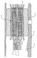
- FIG. 5schematically shows a net or cage in expanded position
- FIG. 6schematically shows a collapsed net or cage placed inside a net or cage in expanded position, the outer circles represent the bag or bellows which is to be inflated and thereby sealing against the well bore wall in a final setting position;
- FIG. 7schematically shows a valve to be used during inflation of the bag or bellows
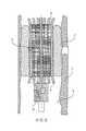
- FIG. 8schematically shows the apparatus, including a running tool, the apparatus being in the expanded position
- FIG. 9schematically shows the apparatus when installed in a section drilled in an earth formation, the intermediate links are not shown;
- FIG. 10schematically shows a side view of a sectional cut through the middle of an embodiment of an elongate member, where an intermediate link(not shown) is to be positioned and locked;
- FIG. 11schematically shows a front view of a sectional cut through the middle of an embodiment of an elongate member, where an intermediate link(not shown) is to be positioned and locked.
- the apparatuscomprises a number of elongate members 1 arranged substantially parallel along a closed curve, where adjacent elongate members 1 are connected via a number of intermediate links 2 , each link 2 being moveable relative to the elongate members 1 it is attached to from an unlocked position to a locked position.
- FIGS. 1 and 2shows a part of a net or cage of elongate members 1 connected with intermediate links 2 in collapsed configuration and FIG. 3 shows the same in an expanded position.
- intermediate links 2can be locked in collapsed position.
- intermediate links 2are held in collapsed position during insertion of the apparatus by means of a flexible member 3 .
- the flexible member 3is an outer bag or bellows 3 .
- the length of the intermediate links 2 and the number of elongate members 1are adapted to form an outer diameter of the apparatus in collapsed state, which outer diameter is smaller than the inner diameter of the apparatus being in an activated state as shown in FIGS. 4 , 5 and 6 .
- the elongate members 1are provided with locking means for holding the intermediate links 2 in a position substantially perpendicular to the elongate members 1 .
- Thisprovides a kind of stiff cage in expanded configuration.
- an apparatus for sealing off a part of a wall 5 in a section 6 drilled into an earth formation and to be placed in the section 6 drilled into the earth formationhas a locking member 7 formed by a groove or ridge 7 extending in a direction substantially perpendicular to the longitudinal direction of the elongate members 1 .
- an inflatable bag or bellows 3is arranged at the outer diameter of the apparatus to form a sealing member against the wall 5 in the section 6 drilled into an earth formation.
- the bag or bellows 3is able to increase the outer diameter of the apparatus by up to more than twice the outer diameter of the cage in expanded configuration.
- elongate members 1is provided with ends sloping in a direction against the wall 5 of the section 6 drilled into an earth formation.
- the sloping endswill then act like a kind of funnel directing equipment through the passage formed by the inner diameter of the apparatus.
- an apparatus for sealing off a part of a wall 5 in a section 6 drilled into an earth formation and to be placed in the section 6 drilled into the earth formationthe apparatus is brought into applied position by inflating a bag or bellows 8 arranged along the inner diameter of the apparatus formed by the elongate members 1 connected with the intermediate links 2 .
- Thismakes it possible to use an available kind of fluid to inflate the bag or bellows 8 and thereby bringing the apparatus into applied position.
- Examples of available fluidscan be fluid from the section 6 drilled in the earth formation or a fluid carried in a running tool 10 .
- any fluid or gas or epoxy or foamcan be used to fill the outer bag or bellows 3 .
- the intermediate links 2 in unlocked positioncan be moved in a plane in the longitudinal direction of the elongate members 1 , thereby making it possible to expand a kind of cage of elongate members 1 by means of intermediate links 2 .
- the intermediate links 2 in unlocked positioncan be moved in a plane substantially perpendicular to the longitudinal direction of the elongate members 1 makes it possible to make a more tight curve of the elongate members 1 .
- the apparatusacquires due to its configuration a reliable collapse resistance, thereby making it possible to maintain an applied sealing using the apparatus.
- An apparatuscan be disabled by simply punching a hole in the outer bag or bellows 3 .
- the apparatuscan be provided with an arrangement for deflating the outer bag or bellows 3 by punching a hole in the bag or bellows 3 or by deflating the bag or bellows 3 by letting out the media enclosed in the bag or bellows 3 , i.e. through a valve or another kind of closable opening 9 .
- an apparatus for sealing off a part of a wall 5 in a section 6 drilled into an earth formation and to be placed in the section 6 drilled into the earth formationcomprising a number of elongate members 1 arranged substantially parallel along a closed curve, where adjacent elongate members 1 are connected via a number of intermediate links 2 , each link 2 being moveable relative to the elongate members 1 it is attached to from an unlocked position to a locked position.
- An apparatus for sealing off a part of a wall 5 in a section 6 drilled into an earth formation and to be placed in the section 6 drilled into the earth formation, where the elongate members 1 are provided with locking means for holding the intermediate links 2 in a position substantially perpendicular to the elongate members 1 ,provides a kind of stiff cage in expanded configuration.
- the intermediate links 2are in locked position, meaning that they can not be moved in such a way that the distance between two neighbouring or two adjacent elongate members 1 are reduced, they will provide the apparatus with a minimum collapse strength of the deployed device.
- the material from which the intermediate link members are selectedhas a minimum of collapse strength of the deployed device in excess of 35 bar.
- the whole assemblycan run on coil tubing (2′′ OD), small drill pipe (31 ⁇ 2′′ OD) or tractor.
- the apparatuscan be equipped with one or more electric cables or batteries to make it possible to use electric current as an energy source.
- FIG. 10schematically shows a side view of a sectional cut through the middle of an embodiment of an elongate member, where an intermediate link (not shown) is to be positioned and locked;
- FIG. 11schematically shows a front view of a sectional cut through the middle of an embodiment of an elongate member, where an intermediate link (not shown) is to be positioned and locked.
- a hydraulic pump(not shown) can provide the apparatus with well fluids (oil, water or a mixture) via a filter to inflate up the outer bag or bellows 3 .
- well fluidsoil, water or a mixture
- a similar arrangement(not shown) is used to inflate the inner bag or bellows 8 to expand the net as shown in FIG. 8 .
- valve 9When inflating the outer bag or bellows 3 a valve 9 can be used.
- the valve 9is connected to the apparatus by a spring activated 11 shear pin 12 .
- the shear pin 12will fail at a predetermined internal pressure and a flexible steel pipe 13 will be ‘pushed’ out by that pressure.
- the valve 9is provided with a reinforcement 15 extending into the inner bellows 8 so that the valve will not detach from the inner bellows 8 .
- a back flow valve 14 together with the shear pin 12ensures that a certain pressure is achieved and that the fluid pressure will not decrease in the bag or bellows 3 when the hydraulic line 13 is detached.
- the inventionalso relates to a method for applying an apparatus for sealing off a part of a wall 5 in a section 6 drilled into an earth formation comprising the steps of:
- the methodfurther describes an embodiment where a further apparatus for sealing off a part of a wall 5 in a section 6 drilled into an earth formation is introduced in collapsed configuration through an inner diameter of an already deployed apparatus.
- a further apparatus for sealing off a part of a wall 5 in a section 6 drilled into an earth formationis introduced in collapsed configuration through a tubing further downhole the drilled section than an already deployed apparatus.
Landscapes
- Geology (AREA)
- Life Sciences & Earth Sciences (AREA)
- Engineering & Computer Science (AREA)
- Mining & Mineral Resources (AREA)
- Environmental & Geological Engineering (AREA)
- Fluid Mechanics (AREA)
- Physics & Mathematics (AREA)
- General Life Sciences & Earth Sciences (AREA)
- Geochemistry & Mineralogy (AREA)
- Earth Drilling (AREA)
- Excavating Of Shafts Or Tunnels (AREA)
- Pipe Accessories (AREA)
- Drilling And Exploitation, And Mining Machines And Methods (AREA)
Abstract
Description
- positioning an apparatus for sealing off a part of a wall in a section drilled into an earth formation with respect to a part of the wall to be sealed of, the apparatus being positioned in collapsed configuration;
- expanding a net or cage in the apparatus, which net or cage is formed by a number of elongate members connected by intermediate links;
- expanding a flexible member arranged at an outer diameter of the apparatus to seal against the wall in the section drilled in the earth formation.
- positioning an apparatus for sealing off a part of a
wall 5 in asection 6 drilled into an earth formation with respect to a part of thewall 5 to be sealed of, the apparatus being positioned in collapsed configuration; - expanding a net or cage in the apparatus, which net or cage is formed by a number of
elongate members 1 connected byintermediate links 2; - expanding a
flexible member 3 arranged at an outer diameter of the apparatus to seal against thewall 5 in thesection 6 drilled in the earth formation.
- positioning an apparatus for sealing off a part of a
Claims (20)
Priority Applications (1)
| Application Number | Priority Date | Filing Date | Title |
|---|---|---|---|
| US13/513,760US9249645B2 (en) | 2009-12-04 | 2010-12-02 | Apparatus for sealing off a part of a wall in a section drilled into an earth formation, and a method for applying the apparatus |
Applications Claiming Priority (6)
| Application Number | Priority Date | Filing Date | Title |
|---|---|---|---|
| US26679009P | 2009-12-04 | 2009-12-04 | |
| DKPA200970245 | 2009-12-04 | ||
| DK200970245 | 2009-12-04 | ||
| DK200970245ADK178339B1 (en) | 2009-12-04 | 2009-12-04 | An apparatus for sealing off a part of a wall in a section drilled into an earth formation, and a method for applying the apparatus |
| US13/513,760US9249645B2 (en) | 2009-12-04 | 2010-12-02 | Apparatus for sealing off a part of a wall in a section drilled into an earth formation, and a method for applying the apparatus |
| PCT/EP2010/068762WO2011067347A1 (en) | 2009-12-04 | 2010-12-02 | An apparatus for sealing off a part of a wall in a section drilled into an earth formation, and a method for applying the apparatus |
Publications (2)
| Publication Number | Publication Date |
|---|---|
| US20130043049A1 US20130043049A1 (en) | 2013-02-21 |
| US9249645B2true US9249645B2 (en) | 2016-02-02 |
Family
ID=42240245
Family Applications (1)
| Application Number | Title | Priority Date | Filing Date |
|---|---|---|---|
| US13/513,760Active2032-10-17US9249645B2 (en) | 2009-12-04 | 2010-12-02 | Apparatus for sealing off a part of a wall in a section drilled into an earth formation, and a method for applying the apparatus |
Country Status (5)
| Country | Link |
|---|---|
| US (1) | US9249645B2 (en) |
| EP (1) | EP2507469B1 (en) |
| DK (2) | DK178339B1 (en) |
| EA (1) | EA025673B1 (en) |
| WO (1) | WO2011067347A1 (en) |
Families Citing this family (1)
| Publication number | Priority date | Publication date | Assignee | Title |
|---|---|---|---|---|
| DK2909427T3 (en) | 2012-10-16 | 2019-11-25 | Total E&P Danmark As | SEALING DEVICE AND PROCEDURE |
Citations (67)
| Publication number | Priority date | Publication date | Assignee | Title |
|---|---|---|---|---|
| US2122697A (en) | 1935-10-01 | 1938-07-05 | Standard Oil Co | Instrument carrier |
| US2271005A (en) | 1939-01-23 | 1942-01-27 | Dow Chemical Co | Subterranean boring |
| FR1561771A (en) | 1967-05-01 | 1969-03-28 | ||
| DE2358371A1 (en) | 1973-11-23 | 1975-05-28 | Koolaj Foldgazbanyaszati | Oil well instrument retrieval device - float connected to instrument has variable specific gravity and own power |
| US3926254A (en) | 1974-12-20 | 1975-12-16 | Halliburton Co | Down-hole pump and inflatable packer apparatus |
| US3937278A (en) | 1974-09-12 | 1976-02-10 | Adel El Sheshtawy | Self-propelling apparatus for well logging tools |
| US4320800A (en) | 1979-12-14 | 1982-03-23 | Schlumberger Technology Corporation | Inflatable packer drill stem testing system |
| US4365676A (en) | 1980-08-25 | 1982-12-28 | Varco International, Inc. | Method and apparatus for drilling laterally from a well bore |
| US4372161A (en) | 1981-02-25 | 1983-02-08 | Buda Eric G De | Pneumatically operated pipe crawler |
| US4611405A (en) | 1981-08-17 | 1986-09-16 | Applied Technologies Associates | High speed well surveying |
| US4621532A (en) | 1984-05-18 | 1986-11-11 | Hitachi, Ltd. | Chain-like self-moving robot and control system therefor |
| US4919223A (en) | 1988-01-15 | 1990-04-24 | Shawn E. Egger | Apparatus for remotely controlled movement through tubular conduit |
| GB2234278A (en) | 1989-07-24 | 1991-01-30 | Robert L Zeer | Deflection apparatus for directional drilling |
| US5070941A (en) | 1990-08-30 | 1991-12-10 | Otis Engineering Corporation | Downhole force generator |
| GB2275066A (en) | 1993-02-16 | 1994-08-17 | Xl Technology Limited | Inflatable well packer |
| US5558153A (en) | 1994-10-20 | 1996-09-24 | Baker Hughes Incorporated | Method & apparatus for actuating a downhole tool |
| WO1998012418A2 (en) | 1996-09-23 | 1998-03-26 | Intelligent Inspection Corporation Commonwealth Of Massachusetts | Autonomous downhole oilfield tool |
| US5758731A (en) | 1996-03-11 | 1998-06-02 | Lockheed Martin Idaho Technologies Company | Method and apparatus for advancing tethers |
| US5955666A (en) | 1997-03-12 | 1999-09-21 | Mullins; Augustus Albert | Satellite or other remote site system for well control and operation |
| WO2000036266A1 (en) | 1998-12-18 | 2000-06-22 | Western Well Tool, Inc. | Electro-hydraulically controlled tractor |
| US6241028B1 (en) | 1998-06-12 | 2001-06-05 | Shell Oil Company | Method and system for measuring data in a fluid transportation conduit |
| US6253850B1 (en)* | 1999-02-24 | 2001-07-03 | Shell Oil Company | Selective zonal isolation within a slotted liner |
| US20010045300A1 (en) | 1998-03-20 | 2001-11-29 | Roger Fincher | Thruster responsive to drilling parameters |
| US20020029908A1 (en) | 1998-12-18 | 2002-03-14 | Duane Bloom | Electrically sequenced tractor |
| GB2368082A (en) | 2000-10-20 | 2002-04-24 | Schlumberger Holdings | Expandable bistable tubing |
| US20020088648A1 (en) | 1997-01-30 | 2002-07-11 | Baker Hughes Incorporated | Drilling assembly with a steering device for coiled -tubing operations |
| EP1223305A2 (en) | 2001-01-16 | 2002-07-17 | Services Petroliers Schlumberger | Bi-stable expandable device and method for expanding such a device |
| US20020096322A1 (en) | 1996-07-13 | 2002-07-25 | Schlumberger Technology Corporation | Down hole tool and method |
| US20020112859A1 (en) | 2000-12-01 | 2002-08-22 | Duane Bloom | Tractor with improved valve system |
| WO2002070943A2 (en) | 2001-03-07 | 2002-09-12 | Carnegie Mellon University | Gas main robotic inspection system |
| US20030102164A1 (en) | 2001-12-05 | 2003-06-05 | Odell Albert C. | Thrust control apparatus |
| US20030192707A1 (en) | 2001-10-03 | 2003-10-16 | Oguzhan Guven | Field weldable connections |
| US20040065445A1 (en)* | 2001-05-15 | 2004-04-08 | Abercrombie Simpson Neil Andrew | Expanding tubing |
| US20040090230A1 (en) | 2002-11-08 | 2004-05-13 | Matthias Appel | Method and apparatus for subterranean formation flow imaging |
| US20040182580A1 (en) | 1995-08-22 | 2004-09-23 | Moore Norman Bruce | Puller-thruster downhole tool |
| US20040226746A1 (en) | 2003-05-15 | 2004-11-18 | Chevron U.S.A. Inc. | Method and system for minimizing circulating fluid return losses during drilling of a well bore |
| US20040226747A1 (en) | 2003-05-15 | 2004-11-18 | Stegmaier Shawn C. | Self-penetrating soil exploration device and associated methods |
| US20040262008A1 (en) | 2003-06-25 | 2004-12-30 | Deans Gregor E. | Subsea communications system |
| US20050150692A1 (en) | 2003-11-05 | 2005-07-14 | Baker Hughes Incorporated | Directional cased hole side track method applying rotary closed loop system and casing mill |
| US20050262944A1 (en) | 2004-04-21 | 2005-12-01 | Symyx Technologies, Inc. | Flexural resonator sensing device and method |
| US20060180316A1 (en) | 2005-02-15 | 2006-08-17 | Steele David J | Assembly of downhole equipment in a wellbore |
| US7230541B2 (en) | 2003-11-19 | 2007-06-12 | Baker Hughes Incorporated | High speed communication for measurement while drilling |
| US20070256861A1 (en) | 2006-05-05 | 2007-11-08 | Hulick Kent E | Bit face orientation control in drilling operations |
| WO2008024881A1 (en) | 2006-08-24 | 2008-02-28 | Western Well Tool, Inc. | Downhole tool with closed loop power systems |
| US20080066963A1 (en) | 2006-09-15 | 2008-03-20 | Todor Sheiretov | Hydraulically driven tractor |
| US20080073077A1 (en) | 2004-05-28 | 2008-03-27 | Gokturk Tunc | Coiled Tubing Tractor Assembly |
| US20080121429A1 (en) | 2004-07-24 | 2008-05-29 | Bamford Anthony S | Subsea Drilling |
| US7392859B2 (en) | 2004-03-17 | 2008-07-01 | Western Well Tool, Inc. | Roller link toggle gripper and downhole tractor |
| US20080159077A1 (en) | 2006-12-29 | 2008-07-03 | Raghu Madhavan | Cable link for a wellbore telemetry system |
| US20080211687A1 (en) | 2005-02-28 | 2008-09-04 | Scientific Drilling International | Electric field communication for short range data transmission in a borehole |
| US20080308318A1 (en) | 2007-06-14 | 2008-12-18 | Western Well Tool, Inc. | Electrically powered tractor |
| US7493967B2 (en) | 2003-02-10 | 2009-02-24 | Western Well Tool, Inc. | Tractor with improved valve system |
| US20090200290A1 (en) | 2007-10-19 | 2009-08-13 | Paul Gregory Cardinal | Variable voltage load tap changing transformer |
| US20090205840A1 (en) | 2008-02-15 | 2009-08-20 | Baker Hughes, Incorporated | Expandable downhole actuator, method of making and method of actuating |
| US20090211754A1 (en) | 2007-06-25 | 2009-08-27 | Turbo-Chem International, Inc. | WirelessTag Tracer Method and Apparatus |
| US20090218105A1 (en) | 2007-01-02 | 2009-09-03 | Hill Stephen D | Hydraulically Driven Tandem Tractor Assembly |
| US20100126716A1 (en) | 2008-11-25 | 2010-05-27 | Baker Hughes Incorporated | Actuator For Downhole Tools |
| US20100133006A1 (en) | 2008-12-01 | 2010-06-03 | Schlumberger Technology Corporation | Downhole communication devices and methods of use |
| US8069917B2 (en) | 2000-05-18 | 2011-12-06 | Wwt International, Inc. | Gripper assembly for downhole tools |
| US20120024539A1 (en) | 2010-07-21 | 2012-02-02 | Baker Hughes Incorporated | Rotary coil tubing drilling and completion technology |
| US8109331B2 (en) | 2009-04-14 | 2012-02-07 | Baker Hughes Incorporated | Slickline conveyed debris management system |
| US8151902B2 (en) | 2009-04-17 | 2012-04-10 | Baker Hughes Incorporated | Slickline conveyed bottom hole assembly with tractor |
| US8245796B2 (en) | 2000-12-01 | 2012-08-21 | Wwt International, Inc. | Tractor with improved valve system |
| US20120292049A1 (en) | 2009-10-30 | 2012-11-22 | Wilhelmus Hubertus Paulus Maria Heijnen | Device and a system and a method of moving in a tubular channel |
| US8430810B2 (en) | 2007-02-12 | 2013-04-30 | Technion Research And Development Foundation, Ltd. | Inflatable balloon device and applications |
| US8602115B2 (en) | 2009-12-01 | 2013-12-10 | Schlumberger Technology Corporation | Grip enhanced tractoring |
| US20140054031A1 (en) | 2011-03-04 | 2014-02-27 | Maersk Olie Og Gas A/S | Method and system for well and reservoir management in open hole completions as well as method and system for producing crude oil |
- 2009
- 2009-12-04DKDK200970245Apatent/DK178339B1/ennot_activeIP Right Cessation
- 2010
- 2010-12-02EAEA201290441Apatent/EA025673B1/ennot_activeIP Right Cessation
- 2010-12-02WOPCT/EP2010/068762patent/WO2011067347A1/enactiveApplication Filing
- 2010-12-02DKDK10794924.0Tpatent/DK2507469T3/enactive
- 2010-12-02EPEP10794924.0Apatent/EP2507469B1/enactiveActive
- 2010-12-02USUS13/513,760patent/US9249645B2/enactiveActive
Patent Citations (87)
| Publication number | Priority date | Publication date | Assignee | Title |
|---|---|---|---|---|
| US2122697A (en) | 1935-10-01 | 1938-07-05 | Standard Oil Co | Instrument carrier |
| US2271005A (en) | 1939-01-23 | 1942-01-27 | Dow Chemical Co | Subterranean boring |
| FR1561771A (en) | 1967-05-01 | 1969-03-28 | ||
| DE2358371A1 (en) | 1973-11-23 | 1975-05-28 | Koolaj Foldgazbanyaszati | Oil well instrument retrieval device - float connected to instrument has variable specific gravity and own power |
| US3937278A (en) | 1974-09-12 | 1976-02-10 | Adel El Sheshtawy | Self-propelling apparatus for well logging tools |
| US3926254A (en) | 1974-12-20 | 1975-12-16 | Halliburton Co | Down-hole pump and inflatable packer apparatus |
| US4320800A (en) | 1979-12-14 | 1982-03-23 | Schlumberger Technology Corporation | Inflatable packer drill stem testing system |
| US4365676A (en) | 1980-08-25 | 1982-12-28 | Varco International, Inc. | Method and apparatus for drilling laterally from a well bore |
| US4372161A (en) | 1981-02-25 | 1983-02-08 | Buda Eric G De | Pneumatically operated pipe crawler |
| US4611405A (en) | 1981-08-17 | 1986-09-16 | Applied Technologies Associates | High speed well surveying |
| US4621532A (en) | 1984-05-18 | 1986-11-11 | Hitachi, Ltd. | Chain-like self-moving robot and control system therefor |
| US4919223A (en) | 1988-01-15 | 1990-04-24 | Shawn E. Egger | Apparatus for remotely controlled movement through tubular conduit |
| GB2234278A (en) | 1989-07-24 | 1991-01-30 | Robert L Zeer | Deflection apparatus for directional drilling |
| US5070941A (en) | 1990-08-30 | 1991-12-10 | Otis Engineering Corporation | Downhole force generator |
| GB2275066A (en) | 1993-02-16 | 1994-08-17 | Xl Technology Limited | Inflatable well packer |
| US5558153A (en) | 1994-10-20 | 1996-09-24 | Baker Hughes Incorporated | Method & apparatus for actuating a downhole tool |
| US7059417B2 (en) | 1995-08-22 | 2006-06-13 | Western Well Tool, Inc. | Puller-thruster downhole tool |
| US20040182580A1 (en) | 1995-08-22 | 2004-09-23 | Moore Norman Bruce | Puller-thruster downhole tool |
| US5758731A (en) | 1996-03-11 | 1998-06-02 | Lockheed Martin Idaho Technologies Company | Method and apparatus for advancing tethers |
| US6845819B2 (en) | 1996-07-13 | 2005-01-25 | Schlumberger Technology Corporation | Down hole tool and method |
| US20020096322A1 (en) | 1996-07-13 | 2002-07-25 | Schlumberger Technology Corporation | Down hole tool and method |
| WO1998012418A2 (en) | 1996-09-23 | 1998-03-26 | Intelligent Inspection Corporation Commonwealth Of Massachusetts | Autonomous downhole oilfield tool |
| US20020088648A1 (en) | 1997-01-30 | 2002-07-11 | Baker Hughes Incorporated | Drilling assembly with a steering device for coiled -tubing operations |
| US5955666A (en) | 1997-03-12 | 1999-09-21 | Mullins; Augustus Albert | Satellite or other remote site system for well control and operation |
| US20010045300A1 (en) | 1998-03-20 | 2001-11-29 | Roger Fincher | Thruster responsive to drilling parameters |
| US6241028B1 (en) | 1998-06-12 | 2001-06-05 | Shell Oil Company | Method and system for measuring data in a fluid transportation conduit |
| US20020029908A1 (en) | 1998-12-18 | 2002-03-14 | Duane Bloom | Electrically sequenced tractor |
| US20020007971A1 (en) | 1998-12-18 | 2002-01-24 | Beaufort Ronald E. | Electro-hydraulically controlled tractor |
| US7174974B2 (en) | 1998-12-18 | 2007-02-13 | Western Well Tool, Inc. | Electrically sequenced tractor |
| US20060196694A1 (en) | 1998-12-18 | 2006-09-07 | Duane Bloom | Electrically sequenced tractor |
| WO2000036266A1 (en) | 1998-12-18 | 2000-06-22 | Western Well Tool, Inc. | Electro-hydraulically controlled tractor |
| US6478097B2 (en) | 1998-12-18 | 2002-11-12 | Western Well Tool, Inc. | Electrically sequenced tractor |
| US6241031B1 (en) | 1998-12-18 | 2001-06-05 | Western Well Tool, Inc. | Electro-hydraulically controlled tractor |
| US6253850B1 (en)* | 1999-02-24 | 2001-07-03 | Shell Oil Company | Selective zonal isolation within a slotted liner |
| US8069917B2 (en) | 2000-05-18 | 2011-12-06 | Wwt International, Inc. | Gripper assembly for downhole tools |
| US8555963B2 (en) | 2000-05-18 | 2013-10-15 | Wwt International, Inc. | Gripper assembly for downhole tools |
| GB2368082A (en) | 2000-10-20 | 2002-04-24 | Schlumberger Holdings | Expandable bistable tubing |
| US7080700B2 (en) | 2000-12-01 | 2006-07-25 | Western Well Tool, Inc. | Tractor with improved valve system |
| US7353886B2 (en) | 2000-12-01 | 2008-04-08 | Western Well Tool, Inc. | Tractor with improved valve system |
| US20040144548A1 (en) | 2000-12-01 | 2004-07-29 | Duane Bloom | Tractor with improved valve system |
| US20080217059A1 (en) | 2000-12-01 | 2008-09-11 | Duane Bloom | Tractor with improved valve system |
| US6679341B2 (en) | 2000-12-01 | 2004-01-20 | Western Well Tool, Inc. | Tractor with improved valve system |
| US7188681B2 (en) | 2000-12-01 | 2007-03-13 | Western Well Tool, Inc. | Tractor with improved valve system |
| US8245796B2 (en) | 2000-12-01 | 2012-08-21 | Wwt International, Inc. | Tractor with improved valve system |
| US20070000693A1 (en) | 2000-12-01 | 2007-01-04 | Duane Bloom | Tractor with improved valve system |
| US20020112859A1 (en) | 2000-12-01 | 2002-08-22 | Duane Bloom | Tractor with improved valve system |
| US7607495B2 (en) | 2000-12-01 | 2009-10-27 | Western Well Tool, Inc. | Tractor with improved valve system |
| EP1223305A2 (en) | 2001-01-16 | 2002-07-17 | Services Petroliers Schlumberger | Bi-stable expandable device and method for expanding such a device |
| WO2002070943A2 (en) | 2001-03-07 | 2002-09-12 | Carnegie Mellon University | Gas main robotic inspection system |
| US20020190682A1 (en) | 2001-03-07 | 2002-12-19 | Hagen Schempf | Gas main robotic inspection system |
| US20040065445A1 (en)* | 2001-05-15 | 2004-04-08 | Abercrombie Simpson Neil Andrew | Expanding tubing |
| US20030192707A1 (en) | 2001-10-03 | 2003-10-16 | Oguzhan Guven | Field weldable connections |
| US20030102164A1 (en) | 2001-12-05 | 2003-06-05 | Odell Albert C. | Thrust control apparatus |
| US20040090230A1 (en) | 2002-11-08 | 2004-05-13 | Matthias Appel | Method and apparatus for subterranean formation flow imaging |
| US7493967B2 (en) | 2003-02-10 | 2009-02-24 | Western Well Tool, Inc. | Tractor with improved valve system |
| US20040226747A1 (en) | 2003-05-15 | 2004-11-18 | Stegmaier Shawn C. | Self-penetrating soil exploration device and associated methods |
| US20040226746A1 (en) | 2003-05-15 | 2004-11-18 | Chevron U.S.A. Inc. | Method and system for minimizing circulating fluid return losses during drilling of a well bore |
| US20040262008A1 (en) | 2003-06-25 | 2004-12-30 | Deans Gregor E. | Subsea communications system |
| US20050150692A1 (en) | 2003-11-05 | 2005-07-14 | Baker Hughes Incorporated | Directional cased hole side track method applying rotary closed loop system and casing mill |
| US7230541B2 (en) | 2003-11-19 | 2007-06-12 | Baker Hughes Incorporated | High speed communication for measurement while drilling |
| US7392859B2 (en) | 2004-03-17 | 2008-07-01 | Western Well Tool, Inc. | Roller link toggle gripper and downhole tractor |
| US7954563B2 (en) | 2004-03-17 | 2011-06-07 | Wwt International, Inc. | Roller link toggle gripper and downhole tractor |
| US7607497B2 (en) | 2004-03-17 | 2009-10-27 | Western Well Tool, Inc. | Roller link toggle gripper and downhole tractor |
| US20050262944A1 (en) | 2004-04-21 | 2005-12-01 | Symyx Technologies, Inc. | Flexural resonator sensing device and method |
| US20080073077A1 (en) | 2004-05-28 | 2008-03-27 | Gokturk Tunc | Coiled Tubing Tractor Assembly |
| US20080121429A1 (en) | 2004-07-24 | 2008-05-29 | Bamford Anthony S | Subsea Drilling |
| US20060180316A1 (en) | 2005-02-15 | 2006-08-17 | Steele David J | Assembly of downhole equipment in a wellbore |
| US20080211687A1 (en) | 2005-02-28 | 2008-09-04 | Scientific Drilling International | Electric field communication for short range data transmission in a borehole |
| US20070256861A1 (en) | 2006-05-05 | 2007-11-08 | Hulick Kent E | Bit face orientation control in drilling operations |
| WO2008024881A1 (en) | 2006-08-24 | 2008-02-28 | Western Well Tool, Inc. | Downhole tool with closed loop power systems |
| US20080066963A1 (en) | 2006-09-15 | 2008-03-20 | Todor Sheiretov | Hydraulically driven tractor |
| US20080159077A1 (en) | 2006-12-29 | 2008-07-03 | Raghu Madhavan | Cable link for a wellbore telemetry system |
| US20090218105A1 (en) | 2007-01-02 | 2009-09-03 | Hill Stephen D | Hydraulically Driven Tandem Tractor Assembly |
| US8430810B2 (en) | 2007-02-12 | 2013-04-30 | Technion Research And Development Foundation, Ltd. | Inflatable balloon device and applications |
| US20080308318A1 (en) | 2007-06-14 | 2008-12-18 | Western Well Tool, Inc. | Electrically powered tractor |
| US20110067926A1 (en) | 2007-06-14 | 2011-03-24 | Wwt International, Inc. | Electrically powered tractor |
| US20090211754A1 (en) | 2007-06-25 | 2009-08-27 | Turbo-Chem International, Inc. | WirelessTag Tracer Method and Apparatus |
| US20090200290A1 (en) | 2007-10-19 | 2009-08-13 | Paul Gregory Cardinal | Variable voltage load tap changing transformer |
| US20090205840A1 (en) | 2008-02-15 | 2009-08-20 | Baker Hughes, Incorporated | Expandable downhole actuator, method of making and method of actuating |
| US20100126716A1 (en) | 2008-11-25 | 2010-05-27 | Baker Hughes Incorporated | Actuator For Downhole Tools |
| US20100133006A1 (en) | 2008-12-01 | 2010-06-03 | Schlumberger Technology Corporation | Downhole communication devices and methods of use |
| US8109331B2 (en) | 2009-04-14 | 2012-02-07 | Baker Hughes Incorporated | Slickline conveyed debris management system |
| US8151902B2 (en) | 2009-04-17 | 2012-04-10 | Baker Hughes Incorporated | Slickline conveyed bottom hole assembly with tractor |
| US20120292049A1 (en) | 2009-10-30 | 2012-11-22 | Wilhelmus Hubertus Paulus Maria Heijnen | Device and a system and a method of moving in a tubular channel |
| US8602115B2 (en) | 2009-12-01 | 2013-12-10 | Schlumberger Technology Corporation | Grip enhanced tractoring |
| US20120024539A1 (en) | 2010-07-21 | 2012-02-02 | Baker Hughes Incorporated | Rotary coil tubing drilling and completion technology |
| US20140054031A1 (en) | 2011-03-04 | 2014-02-27 | Maersk Olie Og Gas A/S | Method and system for well and reservoir management in open hole completions as well as method and system for producing crude oil |
Non-Patent Citations (14)
| Title |
|---|
| "The Development of Novel Down-Hole Intervention Tools, a Change in Well Technology (SPE 122822)", Proceedings of Offshore Europe, Sep. 8, 2009, pp. 1-14, XP055061112, DOI: 10.2118/122822-MS ISBN: 978-1-55-563261-8, the whole document. |
| International Preliminary Report on Patentability for corresponding International application No. PCT/EP2010/068762, dated Nov. 17, 2011. |
| International Preliminary Report on Patentability for International Application No. PCT/EP2010/066376, dated Nov. 30, 2011. |
| International Search Report for corresponding International application No. PCT/EP2010/068762, dated Feb. 7, 2011. |
| International Search Report for International Application No. PCT/EP2010/066376, dated Dec. 8, 2010. |
| International Search Report for PCT/EP2010/066233, mailed Feb. 16, 2011. |
| PCT International-Type Search Report for DK 200901032, dated Apr. 7, 2010,4 pages. |
| PCT/EP2012/052447 International Search Report and Written Opinion, mailed Jul. 5, 2013. |
| Search Report for Application No. PA 200901032, dated Apr. 13, 2010, 1 page. |
| Search Report for Danish Application No. PA 2009 70180, completed Jun. 3, 2010. |
| Search Report for DK application PA 2011 70110, Nov. 7, 2011. |
| Supplemental Search Report for DK application PA-2011-70110, Apr. 16, 2013. |
| Written opinion for PCT/EP2010/066233, mailed Feb. 16, 2011. |
| Written Opinion of the International Searching Authority for corresponding International application No. PCT/EP2010/068762, dated Feb. 7, 2011. |
Also Published As
| Publication number | Publication date |
|---|---|
| EA201290441A1 (en) | 2013-04-30 |
| US20130043049A1 (en) | 2013-02-21 |
| DK2507469T3 (en) | 2014-08-04 |
| DK178339B1 (en) | 2015-12-21 |
| WO2011067347A1 (en) | 2011-06-09 |
| EA025673B1 (en) | 2017-01-30 |
| DK200970245A (en) | 2011-06-05 |
| EP2507469A1 (en) | 2012-10-10 |
| EP2507469B1 (en) | 2014-04-30 |
Similar Documents
| Publication | Publication Date | Title |
|---|---|---|
| US8789581B2 (en) | Flow control devices on expandable tubing run through production tubing and into open hole | |
| EP2206879B1 (en) | Annular barrier and annular barrier system | |
| EP3415711A1 (en) | Downhole patch setting tool | |
| US20150034316A1 (en) | Annular barrier having expansion tubes | |
| CA3001629C (en) | Hydraulic anchoring assembly for insertable progressing cavity pump | |
| US8875790B2 (en) | Method and system for fracking and completing wells | |
| BR112013011805B1 (en) | WELL BOTTOM EQUIPMENT | |
| CN102395753B (en) | Open hole frac system | |
| EP2402554A1 (en) | Fracturing system | |
| EP2436874B1 (en) | Drill pipe | |
| CN109154185A (en) | Underground is across every component | |
| CA2835128C (en) | Method and system for fracking anc completing wells | |
| RU2020120901A (en) | DOWNHOLE REPAIR SYSTEM | |
| US9249645B2 (en) | Apparatus for sealing off a part of a wall in a section drilled into an earth formation, and a method for applying the apparatus | |
| US20110067863A1 (en) | Slurry bypass system for improved gravel packing | |
| US20040031615A1 (en) | Cup seal expansion tool |
Legal Events
| Date | Code | Title | Description |
|---|---|---|---|
| AS | Assignment | Owner name:MAERSK OIL QATAR A/S, DENMARK Free format text:ASSIGNMENT OF ASSIGNORS INTEREST;ASSIGNOR:HEIJNEN, WILHELMUS HUBERTUS PAULUS MARIA;REEL/FRAME:028876/0311 Effective date:20120730 | |
| STCF | Information on status: patent grant | Free format text:PATENTED CASE | |
| AS | Assignment | Owner name:MAERSK OLIE OG GAS A/S, DENMARK Free format text:ASSIGNMENT OF ASSIGNORS INTEREST;ASSIGNOR:MAERSK OIL QATAR A/S;REEL/FRAME:042167/0874 Effective date:20170316 | |
| MAFP | Maintenance fee payment | Free format text:PAYMENT OF MAINTENANCE FEE, 4TH YEAR, LARGE ENTITY (ORIGINAL EVENT CODE: M1551); ENTITY STATUS OF PATENT OWNER: LARGE ENTITY Year of fee payment:4 | |
| AS | Assignment | Owner name:TOTAL E&P DANMARK A/S, DENMARK Free format text:CHANGE OF NAME;ASSIGNOR:MAERSK OLIE OG GAS A/S;REEL/FRAME:051985/0469 Effective date:20180718 | |
| MAFP | Maintenance fee payment | Free format text:PAYMENT OF MAINTENANCE FEE, 8TH YEAR, LARGE ENTITY (ORIGINAL EVENT CODE: M1552); ENTITY STATUS OF PATENT OWNER: LARGE ENTITY Year of fee payment:8 |