US9249582B1 - Interlocking floor panels with high performance locking profiles - Google Patents
Interlocking floor panels with high performance locking profilesDownload PDFInfo
- Publication number
- US9249582B1 US9249582B1US14/541,992US201414541992AUS9249582B1US 9249582 B1US9249582 B1US 9249582B1US 201414541992 AUS201414541992 AUS 201414541992AUS 9249582 B1US9249582 B1US 9249582B1
- Authority
- US
- United States
- Prior art keywords
- locking
- channel
- floor
- wear layer
- base layer
- Prior art date
- Legal status (The legal status is an assumption and is not a legal conclusion. Google has not performed a legal analysis and makes no representation as to the accuracy of the status listed.)
- Active
Links
- 239000004014plasticizerSubstances0.000claimsdescription28
- 125000000391vinyl groupChemical group[H]C([*])=C([H])[H]0.000claimsdescription16
- 229920002554vinyl polymerPolymers0.000claimsdescription16
- 239000000203mixtureSubstances0.000claimsdescription7
- 238000000926separation methodMethods0.000claimsdescription7
- 230000013011matingEffects0.000claimsdescription6
- 230000000295complement effectEffects0.000description11
- 238000009408flooringMethods0.000description11
- 239000011162core materialSubstances0.000description8
- IRIAEXORFWYRCZ-UHFFFAOYSA-NButylbenzyl phthalateChemical compoundCCCCOC(=O)C1=CC=CC=C1C(=O)OCC1=CC=CC=C1IRIAEXORFWYRCZ-UHFFFAOYSA-N0.000description4
- 239000011248coating agentSubstances0.000description4
- 238000000576coating methodMethods0.000description4
- 239000000463materialSubstances0.000description4
- 229920006266Vinyl filmPolymers0.000description3
- 230000008901benefitEffects0.000description3
- BJQHLKABXJIVAM-UHFFFAOYSA-Nbis(2-ethylhexyl) phthalateChemical compoundCCCCC(CC)COC(=O)C1=CC=CC=C1C(=O)OCC(CC)CCCCBJQHLKABXJIVAM-UHFFFAOYSA-N0.000description3
- 238000000034methodMethods0.000description3
- LVAGMBHLXLZJKZ-UHFFFAOYSA-N2-o-decyl 1-o-octyl benzene-1,2-dicarboxylateChemical compoundCCCCCCCCCCOC(=O)C1=CC=CC=C1C(=O)OCCCCCCCCLVAGMBHLXLZJKZ-UHFFFAOYSA-N0.000description2
- KCXZNSGUUQJJTR-UHFFFAOYSA-NDi-n-hexyl phthalateChemical compoundCCCCCCOC(=O)C1=CC=CC=C1C(=O)OCCCCCCKCXZNSGUUQJJTR-UHFFFAOYSA-N0.000description2
- MQIUGAXCHLFZKX-UHFFFAOYSA-NDi-n-octyl phthalateNatural productsCCCCCCCCOC(=O)C1=CC=CC=C1C(=O)OCCCCCCCCMQIUGAXCHLFZKX-UHFFFAOYSA-N0.000description2
- NIQCNGHVCWTJSM-UHFFFAOYSA-NDimethyl phthalateChemical compoundCOC(=O)C1=CC=CC=C1C(=O)OCNIQCNGHVCWTJSM-UHFFFAOYSA-N0.000description2
- DOIRQSBPFJWKBE-UHFFFAOYSA-Ndibutyl phthalateChemical compoundCCCCOC(=O)C1=CC=CC=C1C(=O)OCCCCDOIRQSBPFJWKBE-UHFFFAOYSA-N0.000description2
- FLKPEMZONWLCSK-UHFFFAOYSA-Ndiethyl phthalateChemical compoundCCOC(=O)C1=CC=CC=C1C(=O)OCCFLKPEMZONWLCSK-UHFFFAOYSA-N0.000description2
- MGWAVDBGNNKXQV-UHFFFAOYSA-Ndiisobutyl phthalateChemical compoundCC(C)COC(=O)C1=CC=CC=C1C(=O)OCC(C)CMGWAVDBGNNKXQV-UHFFFAOYSA-N0.000description2
- HBGGXOJOCNVPFY-UHFFFAOYSA-Ndiisononyl phthalateChemical compoundCC(C)CCCCCCOC(=O)C1=CC=CC=C1C(=O)OCCCCCCC(C)CHBGGXOJOCNVPFY-UHFFFAOYSA-N0.000description2
- IPKKHRVROFYTEK-UHFFFAOYSA-Ndipentyl phthalateChemical compoundCCCCCOC(=O)C1=CC=CC=C1C(=O)OCCCCCIPKKHRVROFYTEK-UHFFFAOYSA-N0.000description2
- MQHNKCZKNAJROC-UHFFFAOYSA-Ndipropyl phthalateChemical compoundCCCOC(=O)C1=CC=CC=C1C(=O)OCCCMQHNKCZKNAJROC-UHFFFAOYSA-N0.000description2
- 150000002148estersChemical class0.000description2
- 238000013401experimental designMethods0.000description2
- 239000000945fillerSubstances0.000description2
- 238000009434installationMethods0.000description2
- 239000008029phthalate plasticizerSubstances0.000description2
- 229920000642polymerPolymers0.000description2
- 239000004800polyvinyl chlorideSubstances0.000description2
- 229920000915polyvinyl chloridePolymers0.000description2
- 229920001169thermoplasticPolymers0.000description2
- 239000004416thermosoftening plasticSubstances0.000description2
- BHKLONWXRPJNAE-UHFFFAOYSA-N1-o-butyl 2-o-cyclohexyl benzene-1,2-dicarboxylateChemical compoundCCCCOC(=O)C1=CC=CC=C1C(=O)OC1CCCCC1BHKLONWXRPJNAE-UHFFFAOYSA-N0.000description1
- NJMAFLHPUNGKOD-UHFFFAOYSA-N1-o-butyl 2-o-decyl benzene-1,2-dicarboxylateChemical compoundCCCCCCCCCCOC(=O)C1=CC=CC=C1C(=O)OCCCCNJMAFLHPUNGKOD-UHFFFAOYSA-N0.000description1
- VDFMIRNWHJTMSP-UHFFFAOYSA-N2,3-dihydroxy-4-oxo-4-pentoxybutanoic acidChemical compoundCCCCCOC(=O)C(O)C(O)C(O)=OVDFMIRNWHJTMSP-UHFFFAOYSA-N0.000description1
- SIXWIUJQBBANGK-UHFFFAOYSA-N4-(4-fluorophenyl)-1h-pyrazol-5-amineChemical compoundN1N=CC(C=2C=CC(F)=CC=2)=C1NSIXWIUJQBBANGK-UHFFFAOYSA-N0.000description1
- DVIQCYKDAVBCKR-UHFFFAOYSA-N4-octoxycarbonylbenzoic acidChemical compoundCCCCCCCCOC(=O)C1=CC=C(C(O)=O)C=C1DVIQCYKDAVBCKR-UHFFFAOYSA-N0.000description1
- SESFRYSPDFLNCH-UHFFFAOYSA-NBenzyl benzoateNatural productsC=1C=CC=CC=1C(=O)OCC1=CC=CC=C1SESFRYSPDFLNCH-UHFFFAOYSA-N0.000description1
- 239000004641Diallyl-phthalateSubstances0.000description1
- PYGXAGIECVVIOZ-UHFFFAOYSA-NDibutyl decanedioateChemical compoundCCCCOC(=O)CCCCCCCCC(=O)OCCCCPYGXAGIECVVIOZ-UHFFFAOYSA-N0.000description1
- VOWAEIGWURALJQ-UHFFFAOYSA-NDicyclohexyl phthalateChemical compoundC=1C=CC=C(C(=O)OC2CCCCC2)C=1C(=O)OC1CCCCC1VOWAEIGWURALJQ-UHFFFAOYSA-N0.000description1
- ZVFDTKUVRCTHQE-UHFFFAOYSA-NDiisodecyl phthalateChemical compoundCC(C)CCCCCCCOC(=O)C1=CC=CC=C1C(=O)OCCCCCCCC(C)CZVFDTKUVRCTHQE-UHFFFAOYSA-N0.000description1
- JOYRKODLDBILNP-UHFFFAOYSA-NEthyl urethaneChemical compoundCCOC(N)=OJOYRKODLDBILNP-UHFFFAOYSA-N0.000description1
- 230000004075alterationEffects0.000description1
- 229960002903benzyl benzoateDrugs0.000description1
- 239000011230binding agentSubstances0.000description1
- BCSGAWBQJHXXSE-UHFFFAOYSA-Nbis(11-methyldodecyl) benzene-1,2-dicarboxylateChemical compoundCC(C)CCCCCCCCCCOC(=O)C1=CC=CC=C1C(=O)OCCCCCCCCCCC(C)CBCSGAWBQJHXXSE-UHFFFAOYSA-N0.000description1
- MTYUOIVEVPTXFX-UHFFFAOYSA-Nbis(2-propylheptyl) benzene-1,2-dicarboxylateChemical compoundCCCCCC(CCC)COC(=O)C1=CC=CC=C1C(=O)OCC(CCC)CCCCCMTYUOIVEVPTXFX-UHFFFAOYSA-N0.000description1
- ZFMQKOWCDKKBIF-UHFFFAOYSA-Nbis(3,5-difluorophenyl)phosphaneChemical compoundFC1=CC(F)=CC(PC=2C=C(F)C=C(F)C=2)=C1ZFMQKOWCDKKBIF-UHFFFAOYSA-N0.000description1
- ALEROMXYYSQFLX-UHFFFAOYSA-Nbis(4-methylpentyl) benzene-1,2-dicarboxylateChemical compoundCC(C)CCCOC(=O)C1=CC=CC=C1C(=O)OCCCC(C)CALEROMXYYSQFLX-UHFFFAOYSA-N0.000description1
- RKELNIPLHQEBJO-UHFFFAOYSA-Nbis(5-methylhexyl) benzene-1,2-dicarboxylateChemical compoundCC(C)CCCCOC(=O)C1=CC=CC=C1C(=O)OCCCCC(C)CRKELNIPLHQEBJO-UHFFFAOYSA-N0.000description1
- LGBAGUMSAPUZPU-UHFFFAOYSA-Nbis(9-methyldecyl) benzene-1,2-dicarboxylateChemical compoundCC(C)CCCCCCCCOC(=O)C1=CC=CC=C1C(=O)OCCCCCCCCC(C)CLGBAGUMSAPUZPU-UHFFFAOYSA-N0.000description1
- QUDWYFHPNIMBFC-UHFFFAOYSA-Nbis(prop-2-enyl) benzene-1,2-dicarboxylateChemical compoundC=CCOC(=O)C1=CC=CC=C1C(=O)OCC=CQUDWYFHPNIMBFC-UHFFFAOYSA-N0.000description1
- 125000006487butyl benzyl groupChemical group0.000description1
- 238000009410commercial flooringMethods0.000description1
- 230000008878couplingEffects0.000description1
- 238000010168coupling processMethods0.000description1
- 238000005859coupling reactionMethods0.000description1
- PCYQQSKDZQTOQG-NXEZZACHSA-Ndibutyl (2r,3r)-2,3-dihydroxybutanedioateChemical compoundCCCCOC(=O)[C@H](O)[C@@H](O)C(=O)OCCCCPCYQQSKDZQTOQG-NXEZZACHSA-N0.000description1
- HCQHIEGYGGJLJU-UHFFFAOYSA-Ndidecyl hexanedioateChemical compoundCCCCCCCCCCOC(=O)CCCCC(=O)OCCCCCCCCCCHCQHIEGYGGJLJU-UHFFFAOYSA-N0.000description1
- FBSAITBEAPNWJG-UHFFFAOYSA-Ndimethyl phthalateNatural productsCC(=O)OC1=CC=CC=C1OC(C)=OFBSAITBEAPNWJG-UHFFFAOYSA-N0.000description1
- 229960001826dimethylphthalateDrugs0.000description1
- YCZJVRCZIPDYHH-UHFFFAOYSA-Nditridecyl benzene-1,2-dicarboxylateChemical compoundCCCCCCCCCCCCCOC(=O)C1=CC=CC=C1C(=O)OCCCCCCCCCCCCCYCZJVRCZIPDYHH-UHFFFAOYSA-N0.000description1
- QQVHEQUEHCEAKS-UHFFFAOYSA-Ndiundecyl benzene-1,2-dicarboxylateChemical compoundCCCCCCCCCCCOC(=O)C1=CC=CC=C1C(=O)OCCCCCCCCCCCQQVHEQUEHCEAKS-UHFFFAOYSA-N0.000description1
- -1e.g.Substances0.000description1
- 239000011094fiberboardSubstances0.000description1
- 239000010438graniteSubstances0.000description1
- 238000011900installation processMethods0.000description1
- 230000005923long-lasting effectEffects0.000description1
- 238000012423maintenanceMethods0.000description1
- 239000004579marbleSubstances0.000description1
- VNWKTOKETHGBQD-UHFFFAOYSA-NmethaneNatural productsCVNWKTOKETHGBQD-UHFFFAOYSA-N0.000description1
- 238000012986modificationMethods0.000description1
- 230000004048modificationEffects0.000description1
- CMPQUABWPXYYSH-UHFFFAOYSA-Nphenyl phosphateChemical compoundOP(O)(=O)OC1=CC=CC=C1CMPQUABWPXYYSH-UHFFFAOYSA-N0.000description1
- 239000000049pigmentSubstances0.000description1
- 230000008569processEffects0.000description1
- 238000005096rolling processMethods0.000description1
- 239000010454slateSubstances0.000description1
- 235000012424soybean oilNutrition0.000description1
- 239000003549soybean oilSubstances0.000description1
- 239000003381stabilizerSubstances0.000description1
- 239000004575stoneSubstances0.000description1
- PZTAGFCBNDBBFZ-UHFFFAOYSA-Ntert-butyl 2-(hydroxymethyl)piperidine-1-carboxylateChemical compoundCC(C)(C)OC(=O)N1CCCCC1COPZTAGFCBNDBBFZ-UHFFFAOYSA-N0.000description1
- STCOOQWBFONSKY-UHFFFAOYSA-Ntributyl phosphateChemical compoundCCCCOP(=O)(OCCCC)OCCCCSTCOOQWBFONSKY-UHFFFAOYSA-N0.000description1
- 239000002023woodSubstances0.000description1
Images


Classifications
- E—FIXED CONSTRUCTIONS
- E04—BUILDING
- E04F—FINISHING WORK ON BUILDINGS, e.g. STAIRS, FLOORS
- E04F15/00—Flooring
- E04F15/02—Flooring or floor layers composed of a number of similar elements
- E04F15/02038—Flooring or floor layers composed of a number of similar elements characterised by tongue and groove connections between neighbouring flooring elements
- D—TEXTILES; PAPER
- D06—TREATMENT OF TEXTILES OR THE LIKE; LAUNDERING; FLEXIBLE MATERIALS NOT OTHERWISE PROVIDED FOR
- D06N—WALL, FLOOR, OR LIKE COVERING MATERIALS, e.g. LINOLEUM, OILCLOTH, ARTIFICIAL LEATHER, ROOFING FELT, CONSISTING OF A FIBROUS WEB COATED WITH A LAYER OF MACROMOLECULAR MATERIAL; FLEXIBLE SHEET MATERIAL NOT OTHERWISE PROVIDED FOR
- D06N1/00—Linoleum, e.g. linoxyn, polymerised or oxidised resin
- E—FIXED CONSTRUCTIONS
- E04—BUILDING
- E04C—STRUCTURAL ELEMENTS; BUILDING MATERIALS
- E04C2/00—Building elements of relatively thin form for the construction of parts of buildings, e.g. sheet materials, slabs, or panels
- E04C2/02—Building elements of relatively thin form for the construction of parts of buildings, e.g. sheet materials, slabs, or panels characterised by specified materials
- E04C2/10—Building elements of relatively thin form for the construction of parts of buildings, e.g. sheet materials, slabs, or panels characterised by specified materials of wood, fibres, chips, vegetable stems, or the like; of plastics; of foamed products
- E04C2/20—Building elements of relatively thin form for the construction of parts of buildings, e.g. sheet materials, slabs, or panels characterised by specified materials of wood, fibres, chips, vegetable stems, or the like; of plastics; of foamed products of plastics
- E—FIXED CONSTRUCTIONS
- E04—BUILDING
- E04C—STRUCTURAL ELEMENTS; BUILDING MATERIALS
- E04C2/00—Building elements of relatively thin form for the construction of parts of buildings, e.g. sheet materials, slabs, or panels
- E04C2/02—Building elements of relatively thin form for the construction of parts of buildings, e.g. sheet materials, slabs, or panels characterised by specified materials
- E04C2/10—Building elements of relatively thin form for the construction of parts of buildings, e.g. sheet materials, slabs, or panels characterised by specified materials of wood, fibres, chips, vegetable stems, or the like; of plastics; of foamed products
- E04C2/24—Building elements of relatively thin form for the construction of parts of buildings, e.g. sheet materials, slabs, or panels characterised by specified materials of wood, fibres, chips, vegetable stems, or the like; of plastics; of foamed products laminated and composed of materials covered by two or more of groups E04C2/12, E04C2/16, E04C2/20
- E—FIXED CONSTRUCTIONS
- E04—BUILDING
- E04C—STRUCTURAL ELEMENTS; BUILDING MATERIALS
- E04C2/00—Building elements of relatively thin form for the construction of parts of buildings, e.g. sheet materials, slabs, or panels
- E04C2/02—Building elements of relatively thin form for the construction of parts of buildings, e.g. sheet materials, slabs, or panels characterised by specified materials
- E04C2/26—Building elements of relatively thin form for the construction of parts of buildings, e.g. sheet materials, slabs, or panels characterised by specified materials composed of materials covered by two or more of groups E04C2/04, E04C2/08, E04C2/10 or of materials covered by one of these groups with a material not specified in one of the groups
- E—FIXED CONSTRUCTIONS
- E04—BUILDING
- E04C—STRUCTURAL ELEMENTS; BUILDING MATERIALS
- E04C2/00—Building elements of relatively thin form for the construction of parts of buildings, e.g. sheet materials, slabs, or panels
- E04C2/30—Building elements of relatively thin form for the construction of parts of buildings, e.g. sheet materials, slabs, or panels characterised by the shape or structure
- E—FIXED CONSTRUCTIONS
- E04—BUILDING
- E04F—FINISHING WORK ON BUILDINGS, e.g. STAIRS, FLOORS
- E04F15/00—Flooring
- E04F15/02—Flooring or floor layers composed of a number of similar elements
- E04F15/02177—Floor elements for use at a specific location
- E—FIXED CONSTRUCTIONS
- E04—BUILDING
- E04F—FINISHING WORK ON BUILDINGS, e.g. STAIRS, FLOORS
- E04F15/00—Flooring
- E04F15/02—Flooring or floor layers composed of a number of similar elements
- E04F15/10—Flooring or floor layers composed of a number of similar elements of other materials, e.g. fibrous or chipped materials, organic plastics, magnesite tiles, hardboard, or with a top layer of other materials
- E04F15/105—Flooring or floor layers composed of a number of similar elements of other materials, e.g. fibrous or chipped materials, organic plastics, magnesite tiles, hardboard, or with a top layer of other materials of organic plastics with or without reinforcements or filling materials
- E—FIXED CONSTRUCTIONS
- E04—BUILDING
- E04F—FINISHING WORK ON BUILDINGS, e.g. STAIRS, FLOORS
- E04F15/00—Flooring
- E04F15/02—Flooring or floor layers composed of a number of similar elements
- E04F15/10—Flooring or floor layers composed of a number of similar elements of other materials, e.g. fibrous or chipped materials, organic plastics, magnesite tiles, hardboard, or with a top layer of other materials
- E04F15/107—Flooring or floor layers composed of a number of similar elements of other materials, e.g. fibrous or chipped materials, organic plastics, magnesite tiles, hardboard, or with a top layer of other materials composed of several layers, e.g. sandwich panels
- D—TEXTILES; PAPER
- D06—TREATMENT OF TEXTILES OR THE LIKE; LAUNDERING; FLEXIBLE MATERIALS NOT OTHERWISE PROVIDED FOR
- D06N—WALL, FLOOR, OR LIKE COVERING MATERIALS, e.g. LINOLEUM, OILCLOTH, ARTIFICIAL LEATHER, ROOFING FELT, CONSISTING OF A FIBROUS WEB COATED WITH A LAYER OF MACROMOLECULAR MATERIAL; FLEXIBLE SHEET MATERIAL NOT OTHERWISE PROVIDED FOR
- D06N2211/00—Specially adapted uses
- D06N2211/06—Building materials
- D06N2211/066—Floor coverings
- D—TEXTILES; PAPER
- D10—INDEXING SCHEME ASSOCIATED WITH SUBLASSES OF SECTION D, RELATING TO TEXTILES
- D10B—INDEXING SCHEME ASSOCIATED WITH SUBLASSES OF SECTION D, RELATING TO TEXTILES
- D10B2503/00—Domestic or personal
- D10B2503/04—Floor or wall coverings; Carpets
- E—FIXED CONSTRUCTIONS
- E04—BUILDING
- E04F—FINISHING WORK ON BUILDINGS, e.g. STAIRS, FLOORS
- E04F2201/00—Joining sheets or plates or panels
- E04F2201/01—Joining sheets, plates or panels with edges in abutting relationship
- E04F2201/0138—Joining sheets, plates or panels with edges in abutting relationship by moving the sheets, plates or panels perpendicular to the main plane
- E04F2201/0146—Joining sheets, plates or panels with edges in abutting relationship by moving the sheets, plates or panels perpendicular to the main plane with snap action of the edge connectors
- E—FIXED CONSTRUCTIONS
- E04—BUILDING
- E04F—FINISHING WORK ON BUILDINGS, e.g. STAIRS, FLOORS
- E04F2201/00—Joining sheets or plates or panels
- E04F2201/01—Joining sheets, plates or panels with edges in abutting relationship
- E04F2201/0153—Joining sheets, plates or panels with edges in abutting relationship by rotating the sheets, plates or panels around an axis which is parallel to the abutting edges, possibly combined with a sliding movement
- E04F2201/0161—Joining sheets, plates or panels with edges in abutting relationship by rotating the sheets, plates or panels around an axis which is parallel to the abutting edges, possibly combined with a sliding movement with snap action of the edge connectors
Definitions
- the field of the present inventionrelates to locking floor panel systems in which the floor panels are formed by layers of different materials.
- Interlocking flooring of various typesis well known. Such flooring is often referred to as “floating” because none of the flooring panels, whether they are elongated rectangular boards or less elongated panels, are secured to the subfloor.
- tongue-in-groove floor boardsin which the tongue-in-groove feature provides locking against vertical movement along the two long edges of elongated floor boards—tongue-in-groove flooring did not originally have any locking features along the two short edges of the floor boards. Over time, the long edges of floor panels have gained both horizontal and vertical locking features, as have the short edges.
- U.S. Pat. No. 8,293,058describes one type of interlocking floor panels that has both long and short interlocking edges.
- the locking featuresmay be used with many different types of materials, such as floor panels which have a rigid high density fiberboard (HDF) core, with such HDF core panels having either a hard surface coating or a resilient plasticized vinyl surface coating, or floor panels which have a resilient core with a resilient plasticized vinyl surface.
- HDFhigh density fiberboard
- Embodiments of the present inventionare designed to meeting these needs.
- the present inventionis directed to interlocking floor panels and a system of interlocking floor panels.
- the interlocking floor panelshave a resilient base layer and a wear layer, the wear layer having a higher degree of stiffness than the resilient base layer.
- a floating floor systemincludes a plurality of floor panels, each of the floor panels including: a resilient base layer; a wear layer atop the resilient base layer, the wear layer forming an uppermost surface of the floor panel, the wear layer having a higher degree of stiffness than the resilient base layer; a first locking edge portion having a first locking profile that includes a first horizontal locking feature, a first vertical locking feature, and a first channel having a first channel floor, the first locking edge portion being formed by the wear layer and the resilient base layer, the first locking profile further comprising a first channel bed thickness measured between the uppermost surface and the first channel floor, and wherein the wear layer forms at least 5% of the first channel bed thickness; and a second locking edge portion having a second locking profile that includes a second horizontal locking feature, a second vertical locking feature, and a second vertical ridge, the second locking edge portion located opposite the first locking edge portion; and wherein the floor panels are arranged in a mechanical interlocked arrangement such that the first edge portions of the
- an interlocking floor panelincludes: a resilient base layer; a wear layer atop the resilient base layer, the wear layer forming an uppermost surface of the interlocking floor panel, the wear layer having a higher degree of stiffness than the resilient base layer; a first locking edge portion having a first locking profile that includes a first horizontal locking feature, a first vertical locking feature, and a first channel having a first channel floor, the first locking edge portion being formed by the wear layer and the resilient base layer, the first locking profile further comprising a first channel bed thickness measured between the uppermost surface and the first channel floor, and wherein the wear layer forms at least 5% of the first channel bed thickness; and a second locking edge portion having a second locking profile that includes a second horizontal locking feature, a second vertical locking feature, and a second vertical ridge, the second locking edge portion located opposite the first locking edge portion.
- an interlocking floor panelincludes: a linoleum base layer; a rigid vinyl wear layer atop the linoleum base layer, the rigid vinyl wear layer forming an uppermost surface of the interlocking floor panel; a first locking edge portion having a first locking profile that includes a first horizontal locking feature, a first vertical locking feature, and a first channel having a first channel floor, the first locking edge portion being formed by the rigid vinyl wear layer and the linoleum base layer, the first locking profile further comprising a first channel bed thickness measured between the uppermost surface and the first channel floor; and a second locking edge portion having a second locking profile that includes a second horizontal locking feature, a second vertical locking feature, and a second vertical ridge, the second locking edge portion located opposite the first locking edge portion.
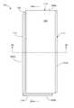
- FIG. 1shows a top plan view of an interlocking floor panel having a resilient base layer and a wear layer having a higher degree of stiffness
- FIG. 2Ashows a sectional view of the floor panel along the line 2 A- 2 A of FIG. 1 ;
- FIG. 2Bshows a sectional view of the floor panel along the line 2 B- 2 B of FIG. 1 ;
- FIG. 3shows a first alternative locking feature configuration for an interlocking floor panel having a resilient base layer and a wear layer having a higher degree of stiffness
- FIG. 4shows a second alternative locking feature configuration for an interlocking floor panel having a resilient base layer and a wear layer having a higher degree of stiffness
- FIG. 5shows a third alternative locking feature configuration for an interlocking floor panel having a resilient base layer and a wear layer having a higher degree of stiffness
- FIG. 6shows a fourth alternative locking feature configuration for an interlocking floor panel having a resilient base layer and a wear layer having a higher degree of stiffness.
- any reference to direction or orientationis merely intended for convenience of description and is not intended in any way to limit the scope of the present invention.
- Relative termssuch as “lower,” “upper,” “horizontal,” “vertical,” “above,” “below,” “up,” “down,” “left,” “right,” “top” and “bottom” as well as derivatives thereof (e.g., “horizontally,” “downwardly,” “upwardly,” etc.) should be construed to refer to the orientation as then described or as shown in the drawing under discussion. These relative terms are for convenience of description only and do not require that the apparatus be constructed or operated in a particular orientation unless explicitly indicated as such.
- the term “rigid”means “unyielding; not pliant or flexible”.
- panelAs used herein, the terms “panel”, “tile”, and “board” may be used interchangeably, and where there is a size or compositional difference, the difference will be expressly stated.
- luxury vinyl flooringsuch as luxury vinyl tile (LVT)
- LVTLuxury vinyl flooring
- a category of thermoplastic based flooring covering productsmay replicate natural materials such as wood, stone, slate, marble, granite, and others.
- Such productsstrive to be more cost effective and offer consumers increased durability and lower maintenance in contrast to their natural counterparts while delivering an equivalent look and feel.
- LVThas particular applicability as a commercial flooring product where it may be subjected to high use and wear. Accordingly, it is desirable to provide a heavy gauge wear layer of suitable thickness to provide durability and longevity.
- the LVT of the exemplary embodimentincludes a resilient base layer formed from any thermoplastic-based composition or mixture suitable for producing resilient laminated flooring.
- the resilient base layermay be a vinyl composition such as PVC mixed with fillers, plasticizers, binders, stabilizers, and/or pigments.
- the resilient base layermay be formed from a plurality of sub-layers, with at least one of the sub-layers having a different composition and different properties.
- the resilient base layermay generally have a thickness ranging from about and including 40 mils (thousandths of an inch) to about and including 250 mils.
- the resilient base layermay have a thickness from about 75 mils to about 145 mils.
- the resilient base layermay have a thickness about 100 mils.
- the plasticizercomprises an ester type plasticizer.
- the ester type plasticizeris selected from: butyl benzyl phthalate, di isononyl phthalate, di octyl terephthalate, tributyl phosphate, dioctyl phthalate, dipropylene glycol dibenzoate, phenyl phosphate, dibutyl tartrate, amyl tartrate, butyl benzyl benzoate, dibutyl sebacate, dioctyl adipate, didecyl adipate and a combination of two or more thereof.
- the plasticizercomprises epoxidized soybean oil.
- the plasticizeris a phthalate plasticizer.
- the phthalate plasticizeris selected from: dimethyl phthalate, diethyl phthalate, diallyl phthalate, di-n-propyl phthalate, di-n-butyl phthalate, diisobutyl phthalate, butyl cyclohexyl phthalate, di-n-pentyl phthalate, dicyclohexyl phthalate, butyl benzyl phthalate, di-n-hexyl phthalate, diisohexyl phthalate, diisoheptyl phthalate, butyl decyl phthalate, di(2-ethylhexyl) phthalate, di(n-octyl) phthalate, diisooctyl phthalate, n-octyl n-decyl phthalate, diisononyl phthalate, di(2-propyl
- the LVT of the exemplary embodimentfurther includes a wear layer formed by a vinyl film, which provides a wear layer that has a higher degree of stiffness than the resilient base layer.
- the vinyl filmmay be a film produced from a vinyl composition, e.g., polyvinyl chloride, with no or substantially no plasticizer (not more than 3%, and for some embodiments, less than 1%).
- the wear layermay be formed of other suitably stiff material layers and/or films.
- the wear layerhas a thickness of at least 2 mils or more to provide a durable and long lasting wear layer for protecting resilient base layer.
- the wear layermay have a thickness of 6 mils, 12 mils, 20 mils, or 22 mils. In yet other embodiments, the wear layer may have a thickness of between about 15 mils and 40 mils. For certain applications of flooring, a thicker wear layer is desirable, so that the LVT may be more suitable for commercial applications to provide satisfactory wear resistance performance to withstand heavy foot traffic and/or other traffic.
- the wear layermay include a pre-embossed, pre-coated, and/or other type of film over an RVF layer.
- the wear layermay include a UV cured urethane top coating to provide enhanced scratch resistance.
- FIG. 1a rectangular floor panel 101 is shown.
- the uppermost surface 103 of the floor panel 101is symmetric to the bottom surface 105 of the floor panel 101 .
- the floor panel 101 as shownhas long edges 107 a , 107 b and short edges 109 a , 109 b .
- Each of the long edges 107 a , 107 bare configured with a first locking profile 111 and a second locking profile 113 , respectively, with the two locking profiles 111 , 113 being complementary in shape to the other locking profile 111 , 113 , respectively, so that the first locking profile 111 of a first floor panel may couple in locking engagement with the second locking profile 113 of a second floor panel.
- each of the short edges 109 a , 109 bmay be configured with a third locking profile 115 and a fourth locking profile 117 , respectively, with the two locking profiles 115 , 117 being complementary in shape to the other locking profile 115 , 117 , respectively, so that the third locking profile 115 of a first floor panel may couple in locking engagement with the second locking profile 117 of a second floor panel.
- one of the long edges 107 a , 107 b or the short edges 109 a , 109 bmay be configured to be of the “fold-and-lock” type, and the other of long edges 107 a , 107 b and the short edges 109 a , 109 b may be configured as a “push-and-lock” type. Both types of locking engagement side profiles are well known in the art, and either type may be placed along the short edge or the long edge of a floor panel.
- the length ratio of the long edges 107 a , 107 b of the floor panel 101 to the short edges 109 a , 109 b of the floor panel 101may vary in accordance with design choice.
- the long edges 107 a , 107 bmay be significantly longer than the short edges 109 a , 109 b , and in other embodiments, all four sides 107 a , 107 b , 109 a , 109 b may be of equal length. When all four sides are equal, the locking profiles are the only features which distinguish the ‘long edges’ from the ‘short edges’.
- each of the wear layer 121 and the resilient base layer 123may include additional sub-layers.
- the wear layer 121 and the resilient base layer 123in combination, form a body portion 125 of the floor panel 101 , and the wear layer 121 and the resilient base layer 123 , in combination, also form the locking edge portion 127 along the first short edge 109 a .
- the resilient base layer 123and not the wear layer 121 , forms the locking edge portion 129 along the second short edge 109 b .
- the wear layer 121may form part of the locking edge portion 129 , with the resilient base layer 123 primarily forming the locking edge portion 129 .
- the locking profile 117 of the first short edge 109 aincludes a horizontal locking feature 131 , which is formed as part of a channel 133 in the locking profile 117 .
- the channel 133is formed by a channel floor 135 , an outer wall surface 137 , and an inner wall surface 139 .
- the outer wall surface 137forms the horizontal locking feature 131 .
- the locking profile 117includes a channel bed thickness 141 measured between the channel floor 135 and the uppermost surface 107 of the floor panel 101 .
- the first channel 133is formed entirely within the resilient base layer 123 . With the channel bed thickness 141 partially formed by the wear layer 121 , the wear layer 121 helps provide additional stiffness to the horizontal locking feature 131 of this first short edge 109 a .
- the wear layer 121forms at least about 5% of the channel bed thickness 141 . In other embodiments, the wear layer 121 may form about 12% of the channel bed thickness 141 , or even about 30% or more of the channel bed thickness 141 .
- the locking profile 119 of the second short edge 109 bincludes a horizontal locking feature 143 which is formed to be complementary in shape to the horizontal locking feature 131 of the locking profile 117 of the first short edge 109 a .
- the locking profile 119also includes a vertical ridge 144 , which includes an inner wall surface 146 and is formed to be complementary to, and to mate with, the channel 133 of the locking profile 117 .
- the inner wall surface 146forms the horizontal locking feature 143 of the floor panel 101 .
- the two locking profiles 117 , 119 along the short edges 109 a , 109 bare configured to provide horizontal locking engagement in a manner that is known in the art—the horizontal locking feature inhibits relative horizontal motion between two adjacent floor panels by interlocking vertically formed, or substantially vertically formed, surfaces.
- the wear layer 121 and the resilient base layer 123in combination, form the locking edge portion 145 along the first long edge 107 a .
- the resilient base layer 123and not the wear layer 121 , forms the locking edge portion 147 along the second long edge 107 b.
- the locking profile 111 of the first long edge 107 aincludes a horizontal locking feature 149 , which is formed as part of a channel 151 in the locking profile 111 , and a vertical locking feature 153 , which is formed as an outward extending tongue 155 .
- the channel 151is formed by a channel floor 155 , an outer wall surface 157 , and an inner wall surface 159 .
- the outer wall surface 157forms the horizontal locking feature 131 .
- the locking profile 111includes a channel bed thickness 161 measured between the channel floor 155 and the uppermost surface 107 of the floor panel 101 .
- the channel 151is formed entirely within the resilient base layer 123 .
- the wear layer 121helps provide additional stiffness to the horizontal locking feature 169 of this first long edge 107 a .
- the wear layer 121forms at least about 5% of the channel bed thickness 161 .
- the wear layer 121may form about 12% of the channel bed thickness 161 , or even about 30% or more of the channel bed thickness 161 .
- the locking profile 113 of the second long edge 107 bincludes a horizontal locking feature 163 , which is formed to be complementary in shape to the horizontal locking feature 149 of the locking profile 111 of the first long edge 107 a , and a vertical locking feature 165 , which is formed to be complementary in shape to the vertical locking feature 155 of the locking profile 111 of the first long edge 107 a .
- the locking profile 113also includes a vertical ridge 150 , which includes an inner wall surface 152 and is formed to be complementary to, and to mate with, the channel 151 of the locking profile 111 .
- the inner wall surface 152forms the horizontal locking feature 163 of the floor panel 101 .
- one floor panel having the first locking profile along a long edgemay be coupled in both locking engagement with a second floor panel having the second locking profile along a long edge.
- the two locking profiles 111 , 113 along the long edges 107 a , 107 bare configured to provide horizontal and vertical locking engagement in a manner that is known in the art—the horizontal locking feature inhibits relative horizontal motion between two adjacent floor panels by interlocking vertically formed, or substantially vertically formed, surfaces, and similarly, the vertical locking feature inhibits relative vertical motion between the two adjacent floor panels by interlocking horizontally formed, or substantially horizontally formed, surfaces.
- the floor panelsmay be arranged in a mechanical interlocked arrangement.
- the first edge portion of each floor panelmates with the second edge portion of adjacent floor panels, with the respective horizontal locking features mating with one another to prevent horizontal separation between the adjacent floor panels, and with the respective vertical locking features mating with one another to prevent vertical separation between the adjacent ones of the floor panels.
- This type of interlocking with adjacent floor panelsmay also be achieved with the locking features shown and described in FIGS. 3-6 below.
- FIG. 3shows portions of two floor panels 201 a , 201 b having alternative locking features in locking engagement, the locking features being configured for “push-to-lock” engagement.
- each floor panel 201 a , 201 bincludes locking profiles 206 a , 206 b having a horizontal locking feature 207 , 209 and a vertical locking feature 211 , 213 .
- the horizontal locking features 207 , 209inhibit relative horizontal motion between the two adjacent floor panels 201 a , 201 b by interlocking vertically formed, or substantially vertically formed, surfaces
- the vertical locking features 211 , 213inhibit relative vertical motion between the two adjacent floor panels 201 a , 201 b by interlocking horizontally formed, or substantially horizontally formed, surfaces.
- the horizontal and vertical locking features 207 , 211 of the first floor panel 201 aare formed as part of a channel 215 .
- the locking profile 206 aincludes a channel floor 217 , an outer wall surface 219 , and an inner wall surface 221 to form the channel 215 .
- the outer wall surface 137forms both the horizontal locking feature 207 and the vertical locking feature 211 .
- the channel floor 217has a channel bed thickness 223 between the channel floor 217 and the uppermost surface 225 of the floor panel 201 a .
- the channel bed thickness 223is formed by both the wear layer 227 and the resilient base layer 229 , however, the channel 215 is formed entirely within the resilient base layer 229 .
- the wear layer 227helps provide additional stiffness to the horizontal locking feature 207 of the floor panel 201 a .
- the wear layer 227forms at least about 5% of the channel bed thickness 223 , and the wear layer 227 may form about 12% of the channel bed thickness 223 , or even about 30% or more of the channel bed thickness 223 .
- the locking profile 206 bincludes a vertical ridge 228 , which includes an inner wall surface 230 and is formed to be complementary to, and to mate with, the channel 215 of the locking profile 206 a .
- the vertical ridge 228is formed entirely within the resilient base layer 229 , and in this embodiment, the inner wall surface 230 forms both the horizontal locking feature 209 and the vertical locking feature 211 of the floor panel 201 b .
- the first floor panel 201 a having the first locking profile 206 a along a long edgemay be coupled in locking engagement with a second floor panel 201 b having the second locking profile 206 b along a long edge.
- the two locking profiles 206 a , 206 bare configured to provide horizontal and vertical locking engagement in a manner that is known in the art.
- FIG. 4shows portions of two floor panels 231 a , 231 b having alternative locking features in locking engagement, the locking features being configured for “fold-to-lock” engagement.
- the floor panels 231 a , 231 bcomprise a UV curable coating 255 .
- each floor panel 231 a , 231 bincludes locking profiles 236 a , 236 b having a horizontal locking feature 237 , 239 and a vertical locking feature 241 , 243 .
- the horizontal locking features 237 , 239inhibit relative horizontal motion between the two adjacent floor panels 231 a , 231 b by interlocking vertically formed, or substantially vertically formed, surfaces
- the vertical locking features 241 , 243inhibit relative vertical motion between the two adjacent floor panels 231 a , 231 b by interlocking horizontally formed, or substantially horizontally formed, surfaces.
- the horizontal locking feature 237 of the first floor panel 231 ais formed as part of a channel 245 .
- the locking profile 236 aincludes a channel floor 247 , an outer wall surface 249 , and an inner wall surface 251 to form the channel 245 .
- the outer wall surface 249forms the horizontal locking feature 237 .
- the channel floor 247has a channel bed thickness 253 between the channel floor 247 and the uppermost surface 253 of the floor panel 231 a .
- the channel bed thickness 253is formed by both the wear layer 257 and the resilient base layer 259 , however, the channel 245 is formed entirely within the resilient base layer 259 .
- the wear layer 257helps provide additional stiffness to the horizontal locking feature 237 of the floor panel 231 a .
- the wear layer 257forms at least about 5% of the channel bed thickness 253 , and the wear layer 257 may form about 12% of the channel bed thickness 253 , or even about 30% or more of the channel bed thickness 253 .
- the locking profile 236 bincludes a vertical ridge 258 , which includes an inner wall surface 260 and is formed to be complementary to, and to mate with, the channel 245 of the locking profile 236 a .
- the vertical ridge 258is formed entirely within the resilient base layer 259 , and in this embodiment, the inner wall surface 260 forms the horizontal locking feature 239 of the floor panel 231 b .
- the first floor panel 231 a having the first locking profile 236 a along a long edgemay be coupled in locking engagement with a second floor panel 231 b having the second locking profile 236 b along a long edge.
- the two locking profiles 236 a , 236 bare configured to provide horizontal and vertical locking engagement in a manner that is known in the art.
- FIG. 5shows portions of two floor panels 261 a , 261 b having top surface 285 and alternative locking features in locking engagement, the locking features being configured for “fold-to-lock” engagement.
- each floor panel 261 a , 261 bincludes locking profiles 266 a , 266 b having a horizontal locking feature 267 , 269 and a vertical locking feature 271 , 273 .
- the horizontal locking features 267 , 269inhibit relative horizontal motion between the two adjacent floor panels 261 a , 261 b by interlocking vertically formed, or substantially vertically formed, surfaces
- the vertical locking features 271 , 273inhibit relative vertical motion between the two adjacent floor panels 261 a , 261 b by interlocking horizontally formed, or substantially horizontally formed, surfaces.
- the horizontal locking feature 267 of the first floor panel 261 ais formed as part of a channel 275 .
- the locking profile 266 aincludes a channel floor 277 , an outer wall surface 279 , and an inner wall surface 281 to form the channel 275 .
- the outer wall surface 279forms the horizontal locking feature 267 .
- the channel floor 277has a channel bed thickness 283 between the channel floor 277 and the uppermost surface 283 of the floor panel 261 a .
- the channel bed thickness 283is formed by both the wear layer 287 and the resilient base layer 289 , however, the channel 275 is formed entirely within the resilient base layer 289 .
- the wear layer 287helps provide additional stiffness to the horizontal locking feature 267 of the floor panel 261 a .
- the wear layer 287forms at least about 5% of the channel bed thickness 283 , and the wear layer 287 may form about 12% of the channel bed thickness 283 , or even about 30% or more of the channel bed thickness 283 .
- the locking profile 266 bincludes a vertical ridge 288 , which includes an inner wall surface 290 and is formed to be complementary to, and to mate with, the channel 275 of the locking profile 266 a .
- the vertical ridge 288is formed entirely within the resilient base layer 289 , and in this embodiment, the inner wall surface 290 forms the horizontal locking feature 269 of the floor panel 261 b .
- the first floor panel 261 a having the first locking profile 266 a along a long edgemay be coupled in locking engagement with a second floor panel 261 b having the second locking profile 266 b along a long edge.
- the two locking profiles 266 a , 266 bare configured to provide horizontal and vertical locking engagement in a manner that is known in the art.
- FIG. 6shows portions of two floor panels 291 a , 291 b having top surface 315 and alternative locking features in locking engagement, the locking features being configured for “fold-to-lock” engagement.
- each floor panel 291 a , 291 bincludes locking profiles 296 a , 296 b having a horizontal locking feature 297 , 299 and a vertical locking feature 301 , 303 .
- the horizontal locking features 297 , 299inhibit relative horizontal motion between the two adjacent floor panels 291 a , 291 b by interlocking vertically formed, or substantially vertically formed, surfaces
- the vertical locking features 301 , 303inhibit relative vertical motion between the two adjacent floor panels 291 a , 291 b by interlocking horizontally formed, or substantially horizontally formed, surfaces.
- the horizontal locking feature 297 of the first floor panel 291 ais formed as part of a channel 305 .
- the locking profile 296 aincludes a channel floor 307 , an outer wall surface 309 , and an inner wall surface 311 to form the channel 305 .
- the outer wall surface 309forms the horizontal locking feature 297 .
- the channel floor 307has a channel bed thickness 313 between the channel floor 307 and the uppermost surface 313 of the floor panel 291 a .
- the channel bed thickness 313is formed by both the wear layer 317 and the resilient base layer 319 , however, the channel 305 is formed entirely within the resilient base layer 319 .
- the wear layer 317helps provide additional stiffness to the horizontal locking feature 297 of the floor panel 291 a .
- the wear layer 317forms at least about 5% of the channel bed thickness 313 , and the wear layer 317 may form about 12% of the channel bed thickness 313 , or even about 30% or more of the channel bed thickness 313 .
- the locking profile 296 bincludes a vertical ridge 318 , which includes an inner wall surface 320 and is formed to be complementary to, and to mate with, the channel 305 of the locking profile 296 a .
- the vertical ridge 318is formed entirely within the resilient base layer 319 , and in this embodiment, the inner wall surface 320 forms the horizontal locking feature 299 of the floor panel 291 b .
- the first floor panel 291 a having the first locking profile 296 a along a long edgemay be coupled in locking engagement with a second floor panel 291 b having the second locking profile 296 b along a long edge.
- the two locking profiles 296 a , 296 bare configured to provide horizontal and vertical locking engagement.
- the degree of stiffness of the wear layerimpacts the performance of the locking profiles described herein.
- the wear layeris rigid.
- the wear layeris substantially stiff.
- the degree of stiffness of the wear layeris modified by the use of a combination of polymers.
- the degree of stiffness of the wear layeris modified by combining polymers (same or different) of varying molecular weights.
- the degree of stiffness of the wear layeris modified by the use of a filler.
- the wear layercomprises less than 20% plasticizer. In some embodiments, the wear layer comprises less than 15% plasticizer. In some embodiments, the wear layer comprises less than 10% plasticizer. In some embodiments, the wear layer comprises less than 5% plasticizer. In some embodiments, the wear layer comprises less than 3% plasticizer. In some embodiments, the wear layer comprises less than 1% plasticizer. In some embodiments, the wear layer is substantially free of plasticizer. In some embodiments, the wear layer is free of plasticizer.
- the base layer of the floor panelcomprises less than 10% plasticizer. In some embodiments, the base layer of the floor panel comprises less than 9% plasticizer. In some embodiments, the base layer of the floor panel comprises less than 8% plasticizer.
- Table 1(below) describes stiffness data generated from three exemplary surface coverings of the present invention.
- the data described in Table 1was generated from an experimental design involving 65 samples with various film and base thicknesses.
- the film and base thicknesses reported in Table 1are based on the results of that 65 sample experimental design.
- the inventive surface coveringsprovide an unexpected level of stiffness, when considered in terms of the stiffness provided by the individual components.
- the use of a vinyl film having ⁇ 20% plasticizer, in combination with a base layer having ⁇ 10% plasticizerprovides an unexpected increase in stiffness over the stiffness provided by each component individually.
Landscapes
- Engineering & Computer Science (AREA)
- Architecture (AREA)
- Civil Engineering (AREA)
- Structural Engineering (AREA)
- Life Sciences & Earth Sciences (AREA)
- Wood Science & Technology (AREA)
- Textile Engineering (AREA)
- Floor Finish (AREA)
Abstract
Description
| TABLE 1 | ||
| Stiffness/inch | ||
| Thickness (mils) | (in-lbs/in) | |
| Film I (w/o plasticizer) | 20 | 14.2 |
| Film II (18% plasticizer) | 20 | 4.2 |
| Base I (7.5% plasticizer) | 100 | 98 |
| Base II (8.8% plasticizer) | 100 | 58 |
| Ex. I | 120 (Base I + Film I) | 245 |
| Ex. II | 120 (Base I + Film II) | 166 |
| Ex. III | 120 (Base II + Film I) | 211 |
Claims (20)
Priority Applications (9)
| Application Number | Priority Date | Filing Date | Title |
|---|---|---|---|
| US14/541,992US9249582B1 (en) | 2014-11-14 | 2014-11-14 | Interlocking floor panels with high performance locking profiles |
| AU2015346020AAU2015346020A1 (en) | 2014-11-14 | 2015-11-16 | Interlocking floor panels with high performance locking profiles |
| CN201580059499.6ACN107109848A (en) | 2014-11-14 | 2015-11-16 | Interlock floor panelling with high-performance locked configuration |
| EP15801076.9AEP3218557A1 (en) | 2014-11-14 | 2015-11-16 | Interlocking floor panels with high performance locking profiles |
| PCT/US2015/060793WO2016077815A1 (en) | 2014-11-14 | 2015-11-16 | Interlocking floor panels with high performance locking profiles |
| US14/994,871US9611655B2 (en) | 2014-11-14 | 2016-01-13 | Interlocking floor panels with high performance locking profiles |
| AU2018279006AAU2018279006A1 (en) | 2014-11-14 | 2018-12-14 | Interlocking floor panels with high performance locking profiles |
| AU2020204257AAU2020204257A1 (en) | 2014-11-14 | 2020-06-26 | Interlocking floor panels with high performance locking profiles |
| AU2022202295AAU2022202295A1 (en) | 2014-11-14 | 2022-04-06 | Interlocking floor panels with high performance locking profiles |
Applications Claiming Priority (1)
| Application Number | Priority Date | Filing Date | Title |
|---|---|---|---|
| US14/541,992US9249582B1 (en) | 2014-11-14 | 2014-11-14 | Interlocking floor panels with high performance locking profiles |
Related Child Applications (1)
| Application Number | Title | Priority Date | Filing Date |
|---|---|---|---|
| US14/994,871ContinuationUS9611655B2 (en) | 2014-11-14 | 2016-01-13 | Interlocking floor panels with high performance locking profiles |
Publications (1)
| Publication Number | Publication Date |
|---|---|
| US9249582B1true US9249582B1 (en) | 2016-02-02 |
Family
ID=54704134
Family Applications (2)
| Application Number | Title | Priority Date | Filing Date |
|---|---|---|---|
| US14/541,992ActiveUS9249582B1 (en) | 2014-11-14 | 2014-11-14 | Interlocking floor panels with high performance locking profiles |
| US14/994,871Expired - Fee RelatedUS9611655B2 (en) | 2014-11-14 | 2016-01-13 | Interlocking floor panels with high performance locking profiles |
Family Applications After (1)
| Application Number | Title | Priority Date | Filing Date |
|---|---|---|---|
| US14/994,871Expired - Fee RelatedUS9611655B2 (en) | 2014-11-14 | 2016-01-13 | Interlocking floor panels with high performance locking profiles |
Country Status (5)
| Country | Link |
|---|---|
| US (2) | US9249582B1 (en) |
| EP (1) | EP3218557A1 (en) |
| CN (1) | CN107109848A (en) |
| AU (4) | AU2015346020A1 (en) |
| WO (1) | WO2016077815A1 (en) |
Cited By (10)
| Publication number | Priority date | Publication date | Assignee | Title |
|---|---|---|---|---|
| US10400457B2 (en)* | 2017-11-27 | 2019-09-03 | Tarkett Gdl S.A. | Synthetic multilayer floor covering |
| US10774292B2 (en) | 2017-05-11 | 2020-09-15 | Ecolab Usa Inc. | Compositions and method for floor cleaning or restoration |
| US10975222B2 (en) | 2017-12-21 | 2021-04-13 | Altro Limited | Organic material |
| USD927020S1 (en)* | 2019-05-24 | 2021-08-03 | Decorstandard Corp | Adhesive tile |
| US20210363760A1 (en)* | 2012-07-02 | 2021-11-25 | Ceraloc Innovation Ab | Panel forming |
| US20220213696A1 (en)* | 2016-11-10 | 2022-07-07 | Flooring Industries Limited, Sarl | Floor panel |
| US11987991B2 (en) | 2019-05-22 | 2024-05-21 | Unilin Bv | Floor panel for forming a floor covering |
| US12234655B2 (en) | 2014-07-04 | 2025-02-25 | Unilin Bv | Floor panel and method for manufacturing floor panels |
| US12264482B2 (en) | 2012-07-02 | 2025-04-01 | Ceraloc Innovation Ab | Panel forming |
| US12442196B2 (en) | 2016-11-22 | 2025-10-14 | Unilin, Bv | Floor panel |
Families Citing this family (12)
| Publication number | Priority date | Publication date | Assignee | Title |
|---|---|---|---|---|
| EA201992325A1 (en)* | 2013-03-25 | 2020-05-31 | Велинге Инновейшн Аб | FLOOR PANELS EQUIPPED WITH MECHANICAL FIXING SYSTEM AND METHOD FOR PRODUCING SUCH FIXING SYSTEM |
| FR3024990B1 (en) | 2014-08-25 | 2018-11-16 | Gerflor | FLOOR PANEL FOR REALIZING A COATING. |
| EP3186459B1 (en) | 2014-08-29 | 2019-06-26 | Välinge Innovation AB | Vertical joint system for a surface covering panel |
| ES2826556T3 (en)* | 2015-01-15 | 2021-05-18 | Flooring Ind Ltd Sarl | Floor panel to form a floor covering |
| US12071770B2 (en) | 2015-01-16 | 2024-08-27 | Unilin Bv | Floor panel for forming a floor covering |
| BE1022985B1 (en)* | 2015-01-16 | 2016-10-27 | Flooring Industries Limited Sarl | Floor panel for forming a floor covering |
| CN107750296A (en)* | 2015-07-06 | 2018-03-02 | 塔吉特Gdl公司 | Chiral flexible rectangular floor covering elements |
| CA3008157C (en) | 2015-12-17 | 2023-08-22 | Valinge Innovation Ab | A method for producing a mechanical locking system for panels |
| BE1023818B1 (en) | 2016-01-15 | 2017-08-01 | Flooring Industries Limited Sarl | Floor panel for forming a floor covering |
| AU2017335148B2 (en) | 2016-09-30 | 2023-04-20 | Välinge Innovation AB | Set of panels assembled by vertical displacement and locked together in the vertical and horizontal direction |
| AU2018400651B2 (en) | 2018-01-09 | 2024-06-13 | Välinge Innovation AB | Set of panels |
| EP3798385A1 (en)* | 2019-09-24 | 2021-03-31 | Välinge Innovation AB | Building panel |
Citations (27)
| Publication number | Priority date | Publication date | Assignee | Title |
|---|---|---|---|---|
| US4804429A (en) | 1987-12-11 | 1989-02-14 | Armstrong World Industries, Inc. | Method of forming a floor tile on a drum |
| US6418683B1 (en)* | 1995-03-07 | 2002-07-16 | Perstorp Flooring Ab | Flooring panel or wall panel and use thereof |
| US20020189183A1 (en)* | 2001-06-19 | 2002-12-19 | Ricciardelli Thomas E. | Decorative interlocking tile |
| US20030024199A1 (en)* | 2001-07-27 | 2003-02-06 | Darko Pervan | Floor panel with sealing means |
| US20030033777A1 (en)* | 2001-08-14 | 2003-02-20 | Bernard Thiers | Floor panel and method for the manufacture thereof |
| US20030145549A1 (en)* | 2000-03-10 | 2003-08-07 | Jorgen Palsson | Vertically joined floor elements comprising a combination of different floor elements |
| US20040211144A1 (en)* | 2001-06-27 | 2004-10-28 | Stanchfield Oliver O. | Flooring panel or wall panel and use thereof |
| US20060101769A1 (en)* | 2004-10-22 | 2006-05-18 | Valinge Aluminium Ab | Mechanical locking system for floor panels |
| US20060179773A1 (en)* | 2005-02-15 | 2006-08-17 | Valinge Aluminium Ab | Building Panel With Compressed Edges And Method Of Making Same |
| US20070175156A1 (en)* | 2006-01-12 | 2007-08-02 | Valinge Innovation Ab | Laminate floor panels |
| US20080028707A1 (en)* | 1998-06-03 | 2008-02-07 | Valinge Innovation Ab | Locking System And Flooring Board |
| US20080168736A1 (en)* | 2002-04-22 | 2008-07-17 | Valinge Innovation Ab | Floorboards, flooring systems and method for manufacturing and installation thereof |
| US20090193748A1 (en)* | 2008-01-31 | 2009-08-06 | Valinge Innovation Belgium Bvba | Mechanical locking of floor panels |
| US20090249733A1 (en)* | 2000-05-16 | 2009-10-08 | Maik Moebus | Panels with coupling means |
| US20100281810A1 (en)* | 2009-05-08 | 2010-11-11 | Carl Ruland | Overlap System For A Flooring System |
| US20110154665A1 (en)* | 2002-03-20 | 2011-06-30 | Valinge Innovation Ab | Floorboards with decorative grooves |
| US20110167744A1 (en) | 2010-01-11 | 2011-07-14 | Mannington Mills, Inc. | Floor Covering With Interlocking Design |
| US8006460B2 (en) | 2007-07-30 | 2011-08-30 | Mannington Mills, Inc. | Floor covering with interlocking design |
| US20120240502A1 (en)* | 2011-03-21 | 2012-09-27 | Steven Wilson | Floating, groutable vinyl floor tile |
| US8293058B2 (en)* | 2003-12-02 | 2012-10-23 | Valinge Innovation Ab | Floorboard, system and method for forming a flooring, and a flooring formed thereof |
| US20120291387A1 (en)* | 2011-05-16 | 2012-11-22 | Craig Patrick Keane | Luxury vinyl tile flooring system |
| US20120317911A1 (en)* | 2010-06-09 | 2012-12-20 | Hong Kong Mei Li Sheng Flooring Co., Limited | Board assembly |
| US8365499B2 (en)* | 2009-09-04 | 2013-02-05 | Valinge Innovation Ab | Resilient floor |
| US20130104478A1 (en)* | 2010-07-09 | 2013-05-02 | Flooring Industries Limited, Sarl | Panel for forming a floor covering |
| US20130111843A1 (en)* | 2009-12-22 | 2013-05-09 | Tarkett Inc. | Surface Covering Tiles having an Edge Treatment for Assembly that Allows for Grouting |
| US20130145707A1 (en)* | 2002-04-08 | 2013-06-13 | Valinge Innovation Ab | Floorboards for flooring |
| US20130263547A1 (en)* | 2012-04-04 | 2013-10-10 | Valinge Innovation Ab | Building panel with a mechanical locking system |
Family Cites Families (8)
| Publication number | Priority date | Publication date | Assignee | Title |
|---|---|---|---|---|
| US4333987A (en)* | 1979-12-19 | 1982-06-08 | Harold Kwart | Methods for bonding dissimilar synthetic polymeric materials and the products involved in and resulting from such methods |
| SE518184C2 (en)* | 2000-03-31 | 2002-09-03 | Perstorp Flooring Ab | Floor covering material comprising disc-shaped floor elements which are joined together by means of interconnecting means |
| WO2006044369A1 (en)* | 2004-10-12 | 2006-04-27 | 3M Innovative Properties Company | Protective film adhesive |
| SE530520C2 (en)* | 2006-01-12 | 2008-06-24 | Vaelinge Innovation Ab | Laminate Panels |
| BE1017157A3 (en)* | 2006-06-02 | 2008-03-04 | Flooring Ind Ltd | FLOOR COVERING, FLOOR ELEMENT AND METHOD FOR MANUFACTURING FLOOR ELEMENTS. |
| WO2010042182A1 (en)* | 2008-10-08 | 2010-04-15 | Armstrong World Industries, Inc. | Flooring panel with first and second decorative surfaces |
| PT2339092T (en)* | 2009-12-22 | 2019-07-19 | Flooring Ind Ltd Sarl | Method for producing covering panels |
| WO2011082491A1 (en)* | 2010-01-07 | 2011-07-14 | Clausi Robert N | Resilient flooring compositions |
- 2014
- 2014-11-14USUS14/541,992patent/US9249582B1/enactiveActive
- 2015
- 2015-11-16WOPCT/US2015/060793patent/WO2016077815A1/enactiveApplication Filing
- 2015-11-16EPEP15801076.9Apatent/EP3218557A1/ennot_activeWithdrawn
- 2015-11-16AUAU2015346020Apatent/AU2015346020A1/ennot_activeAbandoned
- 2015-11-16CNCN201580059499.6Apatent/CN107109848A/enactivePending
- 2016
- 2016-01-13USUS14/994,871patent/US9611655B2/ennot_activeExpired - Fee Related
- 2018
- 2018-12-14AUAU2018279006Apatent/AU2018279006A1/ennot_activeAbandoned
- 2020
- 2020-06-26AUAU2020204257Apatent/AU2020204257A1/ennot_activeAbandoned
- 2022
- 2022-04-06AUAU2022202295Apatent/AU2022202295A1/ennot_activeAbandoned
Patent Citations (28)
| Publication number | Priority date | Publication date | Assignee | Title |
|---|---|---|---|---|
| US4804429A (en) | 1987-12-11 | 1989-02-14 | Armstrong World Industries, Inc. | Method of forming a floor tile on a drum |
| US6418683B1 (en)* | 1995-03-07 | 2002-07-16 | Perstorp Flooring Ab | Flooring panel or wall panel and use thereof |
| US20080028707A1 (en)* | 1998-06-03 | 2008-02-07 | Valinge Innovation Ab | Locking System And Flooring Board |
| US20030145549A1 (en)* | 2000-03-10 | 2003-08-07 | Jorgen Palsson | Vertically joined floor elements comprising a combination of different floor elements |
| US20090249733A1 (en)* | 2000-05-16 | 2009-10-08 | Maik Moebus | Panels with coupling means |
| US20020189183A1 (en)* | 2001-06-19 | 2002-12-19 | Ricciardelli Thomas E. | Decorative interlocking tile |
| US20040211144A1 (en)* | 2001-06-27 | 2004-10-28 | Stanchfield Oliver O. | Flooring panel or wall panel and use thereof |
| US20030024199A1 (en)* | 2001-07-27 | 2003-02-06 | Darko Pervan | Floor panel with sealing means |
| US20030033777A1 (en)* | 2001-08-14 | 2003-02-20 | Bernard Thiers | Floor panel and method for the manufacture thereof |
| US20110154665A1 (en)* | 2002-03-20 | 2011-06-30 | Valinge Innovation Ab | Floorboards with decorative grooves |
| US20130145707A1 (en)* | 2002-04-08 | 2013-06-13 | Valinge Innovation Ab | Floorboards for flooring |
| US8720151B2 (en) | 2002-04-08 | 2014-05-13 | Valinge Innovation Ab | Floorboards for flooring |
| US20080168736A1 (en)* | 2002-04-22 | 2008-07-17 | Valinge Innovation Ab | Floorboards, flooring systems and method for manufacturing and installation thereof |
| US8293058B2 (en)* | 2003-12-02 | 2012-10-23 | Valinge Innovation Ab | Floorboard, system and method for forming a flooring, and a flooring formed thereof |
| US20060101769A1 (en)* | 2004-10-22 | 2006-05-18 | Valinge Aluminium Ab | Mechanical locking system for floor panels |
| US20060179773A1 (en)* | 2005-02-15 | 2006-08-17 | Valinge Aluminium Ab | Building Panel With Compressed Edges And Method Of Making Same |
| US20070175156A1 (en)* | 2006-01-12 | 2007-08-02 | Valinge Innovation Ab | Laminate floor panels |
| US8006460B2 (en) | 2007-07-30 | 2011-08-30 | Mannington Mills, Inc. | Floor covering with interlocking design |
| US20090193748A1 (en)* | 2008-01-31 | 2009-08-06 | Valinge Innovation Belgium Bvba | Mechanical locking of floor panels |
| US20100281810A1 (en)* | 2009-05-08 | 2010-11-11 | Carl Ruland | Overlap System For A Flooring System |
| US8365499B2 (en)* | 2009-09-04 | 2013-02-05 | Valinge Innovation Ab | Resilient floor |
| US20130111843A1 (en)* | 2009-12-22 | 2013-05-09 | Tarkett Inc. | Surface Covering Tiles having an Edge Treatment for Assembly that Allows for Grouting |
| US20110167744A1 (en) | 2010-01-11 | 2011-07-14 | Mannington Mills, Inc. | Floor Covering With Interlocking Design |
| US20120317911A1 (en)* | 2010-06-09 | 2012-12-20 | Hong Kong Mei Li Sheng Flooring Co., Limited | Board assembly |
| US20130104478A1 (en)* | 2010-07-09 | 2013-05-02 | Flooring Industries Limited, Sarl | Panel for forming a floor covering |
| US20120240502A1 (en)* | 2011-03-21 | 2012-09-27 | Steven Wilson | Floating, groutable vinyl floor tile |
| US20120291387A1 (en)* | 2011-05-16 | 2012-11-22 | Craig Patrick Keane | Luxury vinyl tile flooring system |
| US20130263547A1 (en)* | 2012-04-04 | 2013-10-10 | Valinge Innovation Ab | Building panel with a mechanical locking system |
Cited By (17)
| Publication number | Priority date | Publication date | Assignee | Title |
|---|---|---|---|---|
| US20210363760A1 (en)* | 2012-07-02 | 2021-11-25 | Ceraloc Innovation Ab | Panel forming |
| US12264482B2 (en) | 2012-07-02 | 2025-04-01 | Ceraloc Innovation Ab | Panel forming |
| US11781323B2 (en)* | 2012-07-02 | 2023-10-10 | Ceraloc Innovation Ab | Panel forming |
| US12234655B2 (en) | 2014-07-04 | 2025-02-25 | Unilin Bv | Floor panel and method for manufacturing floor panels |
| US12116786B2 (en) | 2016-11-10 | 2024-10-15 | Unilin Bv | Floor panel |
| US20220213696A1 (en)* | 2016-11-10 | 2022-07-07 | Flooring Industries Limited, Sarl | Floor panel |
| US11993939B2 (en) | 2016-11-10 | 2024-05-28 | Unilin, Bv | Floor panel |
| US12006702B2 (en) | 2016-11-10 | 2024-06-11 | Unilin Bv | Floor panel |
| US12116785B2 (en)* | 2016-11-10 | 2024-10-15 | Unilin Bv | Floor panel |
| US12442196B2 (en) | 2016-11-22 | 2025-10-14 | Unilin, Bv | Floor panel |
| US11453844B2 (en) | 2017-05-11 | 2022-09-27 | Ecolab Usa Inc. | Compositions and method for floor cleaning or restoration |
| US10774292B2 (en) | 2017-05-11 | 2020-09-15 | Ecolab Usa Inc. | Compositions and method for floor cleaning or restoration |
| US12275922B2 (en) | 2017-05-11 | 2025-04-15 | Ecolab Usa Inc. | Compositions and method for floor cleaning or restoration |
| US10400457B2 (en)* | 2017-11-27 | 2019-09-03 | Tarkett Gdl S.A. | Synthetic multilayer floor covering |
| US10975222B2 (en) | 2017-12-21 | 2021-04-13 | Altro Limited | Organic material |
| US11987991B2 (en) | 2019-05-22 | 2024-05-21 | Unilin Bv | Floor panel for forming a floor covering |
| USD927020S1 (en)* | 2019-05-24 | 2021-08-03 | Decorstandard Corp | Adhesive tile |
Also Published As
| Publication number | Publication date |
|---|---|
| AU2018279006A1 (en) | 2019-01-17 |
| AU2020204257A1 (en) | 2020-07-16 |
| WO2016077815A1 (en) | 2016-05-19 |
| US20160138274A1 (en) | 2016-05-19 |
| EP3218557A1 (en) | 2017-09-20 |
| US9611655B2 (en) | 2017-04-04 |
| CN107109848A (en) | 2017-08-29 |
| AU2022202295A1 (en) | 2022-04-28 |
| AU2015346020A1 (en) | 2017-06-08 |
Similar Documents
| Publication | Publication Date | Title |
|---|---|---|
| US9611655B2 (en) | Interlocking floor panels with high performance locking profiles | |
| US12281482B2 (en) | Floor covering with interlocking design | |
| US11674318B2 (en) | Panel with locking device | |
| US12435525B2 (en) | Rigid panel for making a floor covering | |
| US11060303B2 (en) | Floor panel for forming a floor covering | |
| EP3175984B1 (en) | Rigid surface covering plastic material | |
| US20200277796A1 (en) | Floor panel for forming a floor covering | |
| WO2015130160A1 (en) | Panel interconnectable with similar panels for forming a covering | |
| KR102649956B1 (en) | Multi-purpose tile systems, tile coverings and tiles | |
| US20230046217A1 (en) | Reversible floor covering element | |
| US20250012094A1 (en) | Sports flooring in tile or plank form | |
| WO2025088483A1 (en) | Covering comprising panels |
Legal Events
| Date | Code | Title | Description |
|---|---|---|---|
| AS | Assignment | Owner name:ARMSTRONG WORLD INDUSTRIES, INC., PENNSYLVANIA Free format text:ASSIGNMENT OF ASSIGNORS INTEREST;ASSIGNORS:ANSPACH, KEAN M.;ESHBACH, JOHN R.;STOLL, BRENT L.;AND OTHERS;SIGNING DATES FROM 20141028 TO 20141030;REEL/FRAME:034177/0703 | |
| AS | Assignment | Owner name:AWI LICENSING COMPANY, DELAWARE Free format text:ASSIGNMENT OF ASSIGNORS INTEREST;ASSIGNOR:ARMSTRONG WORLD INDUSTRIES, INC.;REEL/FRAME:037363/0398 Effective date:20151217 | |
| STCF | Information on status: patent grant | Free format text:PATENTED CASE | |
| AS | Assignment | Owner name:AFI LICENSING LLC, PENNSYLVANIA Free format text:ASSIGNMENT OF ASSIGNORS INTEREST;ASSIGNOR:AWI LICENSING COMPANY;REEL/FRAME:038629/0767 Effective date:20160328 | |
| AS | Assignment | Owner name:BANK OF AMERICA, N.A., AS COLLATERAL AGENT, NEW YORK Free format text:SECURITY INTEREST;ASSIGNOR:AFI LICENSING LLC;REEL/FRAME:040381/0180 Effective date:20160401 Owner name:BANK OF AMERICA, N.A., AS COLLATERAL AGENT, NEW YO Free format text:SECURITY INTEREST;ASSIGNOR:AFI LICENSING LLC;REEL/FRAME:040381/0180 Effective date:20160401 | |
| AS | Assignment | Owner name:AFI LICENSING LLC, PENNSYLVANIA Free format text:RELEASE BY SECURED PARTY;ASSIGNOR:BANK OF AMERICA, N.A., AS COLLATERAL AGENT;REEL/FRAME:047996/0459 Effective date:20181231 | |
| AS | Assignment | Owner name:BANK OF AMERICA, N.A., AS COLLATERAL AGENT, NORTH CAROLINA Free format text:SECURITY INTEREST;ASSIGNOR:AFI LICENSING LLC;REEL/FRAME:047999/0554 Effective date:20181231 Owner name:BANK OF AMERICA, N.A., AS COLLATERAL AGENT, NORTH Free format text:SECURITY INTEREST;ASSIGNOR:AFI LICENSING LLC;REEL/FRAME:047999/0554 Effective date:20181231 | |
| FEPP | Fee payment procedure | Free format text:MAINTENANCE FEE REMINDER MAILED (ORIGINAL EVENT CODE: REM.); ENTITY STATUS OF PATENT OWNER: LARGE ENTITY | |
| FEPP | Fee payment procedure | Free format text:SURCHARGE FOR LATE PAYMENT, LARGE ENTITY (ORIGINAL EVENT CODE: M1554); ENTITY STATUS OF PATENT OWNER: LARGE ENTITY | |
| MAFP | Maintenance fee payment | Free format text:PAYMENT OF MAINTENANCE FEE, 4TH YEAR, LARGE ENTITY (ORIGINAL EVENT CODE: M1551); ENTITY STATUS OF PATENT OWNER: LARGE ENTITY Year of fee payment:4 | |
| AS | Assignment | Owner name:BANK OF AMERICA, N.A., AS COLLATERAL AGENT, NORTH CAROLINA Free format text:CORRECTIVE ASSIGNMENT TO CORRECT THE PROPERTY NUMBERS PREVIOUSLY RECORDED AT REEL: 47999 FRAME: 554. ASSIGNOR(S) HEREBY CONFIRMS THE ASSIGNMENT;ASSIGNOR:AFI LICENSING LLC;REEL/FRAME:052804/0921 Effective date:20181231 | |
| AS | Assignment | Owner name:PATHLIGHT CAPITAL, LP, MASSACHUSETTS Free format text:SECURITY INTEREST;ASSIGNORS:ARMSTRONG FLOORING, INC.;AFI LICENSING, LLC;REEL/FRAME:053033/0726 Effective date:20200623 | |
| AS | Assignment | Owner name:BANK OF AMERICA, N.A., AS COLLATERAL AGENT, NORTH CAROLINA Free format text:SECURITY INTEREST;ASSIGNOR:AFI LICENSING LLC;REEL/FRAME:053731/0016 Effective date:20200623 | |
| AS | Assignment | Owner name:AFI LICENSING LLC, PENNSYLVANIA Free format text:RELEASE BY SECURED PARTY;ASSIGNOR:BANK OF AMERICA, N.A.;REEL/FRAME:060934/0566 Effective date:20220725 Owner name:ARMSTRONG FLOORING, INC., PENNSYLVANIA Free format text:RELEASE BY SECURED PARTY;ASSIGNOR:BANK OF AMERICA, N.A.;REEL/FRAME:060934/0566 Effective date:20220725 Owner name:AFI LICENSING LLC, PENNSYLVANIA Free format text:RELEASE BY SECURED PARTY;ASSIGNOR:BANK OF AMERICA, N.A.;REEL/FRAME:060934/0554 Effective date:20220725 Owner name:ARMSTRONG FLOORING, INC., PENNSYLVANIA Free format text:RELEASE BY SECURED PARTY;ASSIGNOR:BANK OF AMERICA, N.A.;REEL/FRAME:060934/0554 Effective date:20220725 Owner name:AFI LICENSING LLC, PENNSYLVANIA Free format text:RELEASE BY SECURED PARTY;ASSIGNOR:PATHLIGHT CAPITAL LP;REEL/FRAME:060934/0242 Effective date:20220725 Owner name:ARMSTRONG FLOORING, INC., PENNSYLVANIA Free format text:RELEASE BY SECURED PARTY;ASSIGNOR:PATHLIGHT CAPITAL LP;REEL/FRAME:060934/0242 Effective date:20220725 | |
| AS | Assignment | Owner name:AHF, LLC D/B/A AHF PRODUCTS, PENNSYLVANIA Free format text:ASSIGNMENT OF ASSIGNORS INTEREST;ASSIGNOR:AFI LICENSING LLC;REEL/FRAME:062499/0179 Effective date:20220722 | |
| MAFP | Maintenance fee payment | Free format text:PAYMENT OF MAINTENANCE FEE, 8TH YEAR, LARGE ENTITY (ORIGINAL EVENT CODE: M1552); ENTITY STATUS OF PATENT OWNER: LARGE ENTITY Year of fee payment:8 |